CalAmp Wireless Networks BDP3-AMP Amplifier User Manual TITLE
CALAMP WIRELESS NETWORKS INC. Amplifier TITLE
Manual

i
Paragon-III (700MHz)
Data Base Station
(With Amplifier Technologies 70W PA)
User Manual
Version 1.00a
Preliminary – For Internal Use Only
The entire contents of this manual are copyright 2005 by DATARADIO Inc.
Copyright DATARADIO Inc.
April 2005
Part no.: 120 20191-100a

120 40515-100a HiPR900 User Manual
ii
1. PRODUCT OVERVIEW...................................................................................................................................1
1.1 INTENDED AUDIENCE ........................................................................................................................................1
1.2 GENERAL DESCRIPTION.....................................................................................................................................1
1.2.1 Features...................................................................................................................................................2
1.2.2 Configuration...........................................................................................................................................2
1.3 FACTORY TECHNICAL SUPPORT ........................................................................................................................3
1.4 PRODUCT WARRANTY.......................................................................................................................................4
1.5 REPLACEMENT PARTS .......................................................................................................................................4
1.5.1 Factory Repair.........................................................................................................................................4
1.6 PACKAGING.......................................................................................................................................................4
2. INSTALLATION................................................................................................................................................5
2.1 OVERVIEW ........................................................................................................................................................5
2.2 LOCATION .........................................................................................................................................................5
2.3 FRONT VIEW .....................................................................................................................................................5
REAR VIEWS ..............................................................................................................................................................7
2.5 ELECTRICAL......................................................................................................................................................8
2.5.1 Paragon-III Assembly Power ..................................................................................................................8
2.6 POWER AMPLIFIER ............................................................................................................................................9
2.7 ANTENNA........................................................................................................................................................10
2.7.1 Overview................................................................................................................................................10
2.7.2 Cabling and Connection........................................................................................................................10
2.8 COMPLETING THE PHYSICAL INSTALLATION....................................................................................................10
2.9 CHECKING OUT NORMAL OPERATION .............................................................................................................10
3. OPERATING DESCRIPTION .......................................................................................................................11
3.1 RADIO ASSEMBLY ...........................................................................................................................................11
Diversity SDR Rx module ...................................................................................................................................11
3.1.2 5W Transmitter module .........................................................................................................................12
3.1.3 70W Power Amplifier ............................................................................................................................12
3.1.4 BSC module ...........................................................................................................................................13
3.1.5 Speaker panel ........................................................................................................................................13
3.1.6 Power Supply Modules..........................................................................................................................14
3.1.7 Radio Backplane Assembly....................................................................................................................16
3.2 ONLINE & OFFLINE DIAGNOSTICS...................................................................................................................16
4. OPERATION & CONFIGURATION............................................................................................................17
4.1 BROWSER-BASED SETUP AND STATUS ............................................................................................................17
4.2 DEFAULT IP SETTINGS ....................................................................................................................................17
4.2.1 Ethernet Interface 1 (DATA)..................................................................................................................17
4.2.2 Ethernet Interface 2 (SETUP)................................................................................................................17
4.2.3 RF Interface...........................................................................................................................................17
4.3 IP NETWORK SETTINGS...................................................................................................................................18
4.3.1 IP Network Settings (with Host) ............................................................................................................18
4.3.2 IP Network Settings (with Router).........................................................................................................18
4.4 LAN SETUP.....................................................................................................................................................19
4.5 LOGIN SCREEN ................................................................................................................................................19
4.5.1 Initial Installation Login........................................................................................................................19
4.6 SECURITY SETUP.............................................................................................................................................20
4.7 INTERFACE ......................................................................................................................................................20
4.7.1 Apply Parameters & Save Parameters Buttons Behavior .....................................................................21
4.7.2 Unit Status .............................................................................................................................................22

120 40515-100a HiPR900 User Manual
iii
5. TROUBLE-SHOOTING AND TESTING .....................................................................................................26
5.1 EQUIPMENT REQUIRED....................................................................................................................................26
5.2 RECOMMENDED CHECKS.................................................................................................................................26
5.3 ADDITIONAL TEST DETAILS .............................................................................................................................30
5.3.1 RF Data Link Test..................................................................................................................................30
5.4 WINDOWS/UNIX TOOLS ..................................................................................................................................31
5.4.1 Network Connectivity.............................................................................................................................31
5.4.2 Configuration Information ....................................................................................................................31
5.4.3 Statistics Information.............................................................................................................................32
6. RADIO PROGRAMMING AND ADJUSTMENTS .....................................................................................33
6.1 T881-10 RADIO TRANSMITTER PROGRAMMING..............................................................................................33
6.1.1 Recommended Items ..............................................................................................................................33
6.1.2 T881-10 Module Programming.............................................................................................................33
6.1.3 Channel Selection via DIP Switches......................................................................................................35
6.2 TRANSMITTER RADIO TUNING ........................................................................................................................36
6.2.1 Test Equipment ......................................................................................................................................36
6.2.2 Transmitter Module (T881-10-02200)...................................................................................................36
7. SPECIFICATIONS ..........................................................................................................................................39
FIGURE 1 - TYPICAL RACK-MOUNT MULTI-MODULES "RADIO ASSEMBLY" ....................................................................5
FIGURE 2 – AMPLIFIER TECHNOLOGIES INC 70W POWER AMPLIFIER............................................................................6
FIGURE 3 - INDICATORS AND POWER ADJUSTMENT CONTROL .......................................................................................6
FIGURE 4 – POWER AMPLIFIER’S DC POWER AND RF CONNECTORS.............................................................................6
FIGURE 5 - PARAGON-III REAR VIEW .............................................................................................................................7
FIGURE 6 - BACKPLANE .................................................................................................................................................7
FIGURE 7 - MAXI-FUSE ..................................................................................................................................................9
FIGURE 8 - RECEIVER MODULE.....................................................................................................................................11
FIGURE 9 – 5W EXCITER MODULE ...............................................................................................................................12
FIGURE 10 - BSC MODULE...........................................................................................................................................13
FIGURE 11 - SPEAKER MODULE ....................................................................................................................................13
FIGURE 12 - T-809 POWER SUPPLY MODULE...............................................................................................................14
FIGURE 13 - T809 REAR PANEL....................................................................................................................................15
FIGURE 14 - RADIO BACKPLANE ASSEMBLY................................................................................................................16
FIGURE 15 - IP NETWORK SETTINGS IN ROUTER MODE (WITH HOST)..........................................................................18
FIGURE 16 - IP NETWORK SETTINGS IN ROUTER MODE (WITH ROUTER) .....................................................................18
FIGURE 17 - ENTER NETWORK PASSWORD SCREEN – ETH1 DATA PORT SHOWN ........................................................19
FIGURE 18 - WEB USER INTERFACE (PRELIMINARY – HIPR-900 MODEL SHOWN).......................................................20
FIGURE 19 - PARAMETER COMMAND BUTTONS BEHAVIOR ..........................................................................................21
FIGURE 20 - STATION RESET CONFIRMATION ..............................................................................................................21
FIGURE 21 - EXCITER SYSTEM INFOMATION SAMPLE...................................................................................................34
FIGURE 22 - EXCITER CHANNEL INFORMATION SAMPLE..............................................................................................34
FIGURE 23 - BACKPLANE DIP SWITCHES EXAMPLE - CHANNEL 1 SELECTED................................................................35
FIGURE 24 - T881-0200 TRANSMITTER TUNING CONTROLS LOCATION .......................................................................38
TABLE 1 - ON-AIR DATA SPEEDS AND MODULATION TYPES ............................................................................................2
TABLE 2 - 70W POWER AMPLIFIER INDICATORS..........................................................................................................12
TABLE 3 - UNIT STATUS...............................................................................................................................................22
TABLE 4 - SETUP (GENERAL).......................................................................................................................................22
TABLE 5 - BASIC IP CONFIGURATION ..........................................................................................................................22
TABLE 6 - RF SETUP ....................................................................................................................................................22
TABLE 7 - TERMINAL SERVER CONFIGURATION...........................................................................................................22
TABLE 8 - ADVANCED IP CONFIGURATION..................................................................................................................23
120 40515-100a HiPR900 User Manual
iv
TABLE 9 - RF NETWORK SETUP...................................................................................................................................23
TABLE 10 - BROADCAST / MULTICAST.........................................................................................................................23
TABLE 11 - IP OPTIMIZATION & TUNING.....................................................................................................................24
TABLE 12 - SIMPLE NETWORK TIME PROTOCOL ..........................................................................................................24
TABLE 13 - SECURITY ..................................................................................................................................................24
TABLE 14 - NETWORK..................................................................................................................................................24
TABLE 15 - PACKET STATISTICS...................................................................................................................................25
TABLE 16 - RF TEST ....................................................................................................................................................25
TABLE 17 - FTP TRANSFER..........................................................................................................................................25
TABLE 18 - RSSI TABLE ..............................................................................................................................................25
TABLE 19 - MANUALS & SUPPORT...............................................................................................................................25
TABLE 20 - CHECKLIST A (AFTER INSTALLATION) ......................................................................................................27
TABLE 21 - CHECKLIST B (GENERAL)..........................................................................................................................28

120 40515-100a HiPR900 User Manual
v
WHAT'S NEW
History
Version 1.00a: April 2005 – Preliminary,
- With optional Amplifier Technologies 70W PA
Version 0.02: October 2004 – issue 0.02, preliminary.
- With optional Aethercomm 50W PA as Annex A.
Version 0.01: April 2004 –first issue, preliminary

120 40515-100a HiPR900 User Manual
vi
About Dataradio
Dataradio is a leading designer and manufacturer of advanced wireless data products and systems for mis-
sion critical applications. Our products are found at the heart of mobile data and SCADA networks
around the world.
With over 20 years dedicated to data technology and innovation, Dataradio is the premier source for
wireless data solutions. Our products include mobile data products, telemetry devices, integrated wireless
modems for fixed point-to-point and point to multi-point applications, and OEMs. Our product line is one
of the broadest in the industry covering the most often-used frequency bands.
www.dataradio.com
Dataradio provides product brochures, case studies software downloads and product information on our
website. Every effort is taken to provide accurate, timely product information in this user manual.
Product updates may result in differences between the information provided herein and the product
shipped. The information in this document is subject to change without notice.
DATARADIO is a registered trademark, Gemini-G3, Paragon, Paragon PD, Paragon-III and PARALLEL
DECODE are trademarks of Dataradio Inc
120 40515-100a HiPR900 User Manual
vii
Definitions
Access Point Communication hub for users to connect to a wired LAN. APs are important for
providing heightened wireless security.
AES Advanced Encryption Standard (AES) - uses 128-bit encryption to secure data.
Airlink Physical radio frequency connections used for communications between units.
ARP Address Resolution Protocol – Maps Internet address to physical address.
Asynchronous Information that can be sent at random times, and not synchronized to a clock.
Transmission characters begin with a “start” bit and end with a “stop” bit.
AVL Automatic Vehicle Location. Optional feature that involves using GPS (Global
Positioning System) signals from the mobile unit by the Host PC.
Backbone The part of a network that connects most of the systems and networks together,
and handles the most data.
Bandwidth The transmission capacity of a given device or network.
Browser An application program that provides a way to look at and interact with all the in-
formation on the World Wide Web.
BSC Base Station Controller - An async controller-modem designed for the radio base
station in mobile systems. A component of Paragon-III™.
CDip Windows based "Commands & Data over IP" radio-modem Software. This soft-
ware allows basic tests, unit configuration, and troubleshooting.
COM Port RS-232 serial communications ports of the Paragon-III wireless radiomodem.
Default Gateway A device that forwards Internet traffic from your local area network.
DHCP Dynamic Host Configuration Protocol - A networking protocol that allows ad-
ministrators to assign temporary IP addresses to network computers by "leasing"
an IP address to a user for a limited amount of time, instead of assigning perma-
nent IP addresses.
DNS Domain Name Server - translates the domain name into an IP address.
Domain A specific name for a network of computers.
Dynamic IP Addr A temporary IP address assigned by a DHCP server.
E-DBA Dataradio’s Enhanced Dynamic Bandwidth Allocation airlink protocol.
Ethernet IEEE standard network protocol that specifies how data is placed on and re-
trieved from a common transmission medium.
Firewall A set of related programs located at a network gateway server that protects the
resources of a network from users from other networks.
Firmware The programming code that runs a networking device.
Fragmentation Breaking a packet into smaller units when transmitting over a network medium
that cannot support the original size of the packet.
FTP File Transfer Protocol - A protocol used to transfer files over a TCP/IP network.
120 40515-100a HiPR900 User Manual
viii
Gateway A device that interconnects networks with different, incompatible communica-
tions protocols.
Gemini-G3 High specs dual DSP mobile radiomodem with Dataradio Parallel Decode™
technology
HDX Half Duplex. Data transmission that can occur in two directions over a single
line, using separate Tx and Rx frequencies, but only one direction at a time.
HTTP HyperText Transport Protocol - The communications protocol used to connect to
servers on the World Wide Web.
IPCONFIG A Windows 2000 and XP utility that displays the IP address for a particular net-
working device.
MAC Media Access Control - The unique address that a manufacturer assigns to each
networking device.
NAT Network Address Translation - NAT technology translates IP addresses of a local
area network to a different IP address for the Internet.
Network A series of computers or devices connected for the purpose of data sharing, stor-
age, and/or transmission between users.
Network speed This is the bit rate on the RF link between units.
Node A network junction or connection point, typically a computer or work station.
OIP Optimized IP – Compresses TCP and UDP headers, and filters unnecessary ac-
knowledgments. This makes the most use of the available bandwidth.
OTA Over-The-Air - Standard for the transmission and reception of application-related
information in a wireless communications system
Paragon-III IP-based data radio base station used in mobile networks and designed specifi-
cally to fit the needs of vehicular applications. Runs up to 128 kb/s
Parallel Decode Technology featuring dual receivers for added data decode sensitivity in multi-
path and fading environments.
Ping Packet INternet Groper - An Internet utility used to determine whether a particu-
lar IP address is online.
PLC Programmable Logic Controller. An user-provided intelligent device that can
make decisions, gather and report information, and control other devices.
Router A networking device that connects multiple networks together.
RS-232 Industry–standard interface for data transfer.
Static IP Address A fixed address assigned to a computer or device that is connected to a network.
Static Routing Forwarding data in a network via a fixed path.
Subnet Mask An address code that determines the size of the network.
Switch A data switch that connects computing devices to host computers, allowing a
large number of devices to share a limited number of ports.
Sync Data transmitted on a wireless network that keeps the network synchronized.
TCP Transmission Control Protocol - A network protocol for transmitting data that re-
quires acknowledgement from the recipient of data sent.
TCP/IP Transmission Control Protocol/Internet Protocol - A set of instructions PCs use
to communicate over a network.
Telnet A user command and TCP/IP protocol used for accessing remote PCs.
120 40515-100a HiPR900 User Manual
ix
TFTP Trivial File Transfer Protocol - A version of the TCP/IP FTP protocol that has no
directory or password capability.
Topology The physical layout of a network.
Transparent A transparent unit transmits all data without regard to special characters, etc.
UDP User Datagram Protocol - A network protocol for transmitting data that does not
require acknowledgement from the recipient of the data that is sent.
Upgrade To replace existing software or firmware with a newer version.
URL Universal Resource Locator - The address of a file located on the Internet.
VIS Vehicular Information Solutions. Dataradio’s name for a series of products spe-
cially designed for mobile data.
VPN Virtual Private Network - A security measure to protect data as it leaves one net-
work and goes to another over the Internet.
WINIPCFG A Windows 98 and Me utility that displays the IP address for a particular net-
working device.
WLAN Wireless Local Area Network - A group of computers and associated devices that
communicate with each other wirelessly.
120 20191-100a Paragon-III User Manual
1
1. PRODUCT OVERVIEW
This document provides information required for the setting up, operation, testing and trouble-shooting of
the Dataradio® Paragon-III™ radio-modem base station.
1.1 Intended Audience
This document is intended for engineering, installation, and maintenance personnel.
1.2 General Description
The Paragon-III product is a factory-integrated industrial-grade IP-based data radio base station used in
mobile networks and is designed specifically to fit the needs of vehicular applications. The 700MHz version
features diversity Software Defined Radio (SDR) receivers for added data decode sensitivity in multi-path
and fading environments.
When used with Dataradio’s state-of-the-art Gemini-G3 mobile IP data solution, the system delivers
unequaled high-speed data performance and unmatched effective throughput.
All Paragon-III models are supplied in a rackmount configuration that includes:
• A Paragon-III full-duplex radio-modem assembly that includes a Next generation high-speed Dataradio
third generation “Base Station Controller” module (BSC) fitted in the radio chassis assembly.
• A 70W power amplifier (model SRA7070B) manufactured by Amplifier Technologies Inc. supplied in a
stand-alone rackmount configuration. It is DC-powered by the Paragon-III.
• Duplexer and backup power units are custom furnished items.
• Wire line modem(s) are optional items.
• Laptop PC and its application software are user-supplied items.

120 20191-100a Paragon-III User Manual
2
1.2.1 Features
• Parallel Decode (PD) technology featuring a diversity SDR receiver module for added decode
sensitivity in multi-path and fading environments.
• Fully IP based product line, using an optimized IP layer that reduces IP overhead for the RF link
• Sophisticated dual DSP-based modem design provides added system performance, fewer retries
and more effective throughput.
• 700MHz / 50kHz channels for the Public Safety band of operation:
766-773 MHz TX (under FCC part 90) and 762-764 MHz TX (under FCC part 27)
• Full duplex operation in the 700MHz frequency band
• Base Station with 70W RF Power Amplifier (user adjustable from 35W)
• On-air data speeds and modulation types supported:
Table 1 - On-air data speeds and modulation types
Modulation type Channel spacing – 50kHz
SRC4FSK 64 kb/s
SRC8FSK 96 kb/s
SRC16FSK 128 kb/s
• Uses the Next generation high-efficiency Dataradio Enhanced-DBA over-the-air protocol
• Over-the-air compatible with Gemini-G3 mobile products
• Out-of-band signaling enables transmission of GPS reports with no effect on system performance.
• Flash programmable firmwares, including over-the-air programming capability
• Paragon-III units are factory-configured based on each customer’s network system requirements
1.2.2 Configuration
Paragon-III units are factory-configured to default settings. Configuration changes or upgrades are web-
based.

120 20191-100a Paragon-III User Manual
3
1.3 Factory Technical Support
The Technical Support departments of DATARADIO provide customer assistance on technical prob-
lems and serve as an interface with factory repair facilities. They can be reached in the following
ways:
For Canada and International customers:
DATARADIO Inc.
5500 Royalmount Ave, suite 200
Town of Mount Royal
Quebec, Canada H4P 1H7
Technical support hours: Monday to Friday 9:00 AM to 5:00 PM, Eastern Time
phone: +1 514 737-0020
fax: +1 514 737-7883
Email address: support@dataradio.com
or
For U.S. customers:
DATARADIO Corp.
6160 Peachtree Dunwoody RD., suite C-200
Atlanta, Georgia 30328
Technical support hours: Monday to Friday 9:00 AM to 5:00 PM, Eastern Time
phone: 1 770 392-0002
fax: 1 770 392-9199
Email address: drctech@dataradio.com
120 20191-100a Paragon-III User Manual
4
1.4 Product Warranty
Warranty information may be obtained by contacting your sales representative.
1.5 Replacement Parts
This product is usually not field-serviceable, except by the replacement of individual radio modules.
Specialized equipment and training is required to repair logic, modem boards, and radio modules.
Contact Technical Support for service information before returning equipment. A Technical Support
representative may suggest a solution eliminating the need to return equipment.
1.5.1 Factory Repair
When returning equipment for repair, you must request an RMA (Returned Material Authorization)
number. The Tech Support representative will ask you several questions to clearly identify the prob-
lem. Please give the representative the name of a contact person, who is familiar with the problem,
should a question arise during servicing of the unit.
Customers are responsible for shipping charges for returned units. Units in warranty will be repaired
free of charge unless there is evidence of abuse or damage beyond the terms of the warranty. Units
out of warranty will be subject to service charges. Information about these charges is available from
Technical Support.
1.6 Packaging
Each Paragon-III – 700MHz product normally leaves the factory packaged as follows:
• A Dataradio base station “Radio-modem assembly”
• A rackmount 70W power amplifier assembly
• One standard seven-foot 120VAC power cord
• DC power harness to connect the radio assembly to the power amplifier rackmount assembly.
Frequently, Paragon-III product components are field-assembled prior to customer delivery.
The cabinetry may then be supplied in one of several custom rack-mount configurations that may also in-
clude fan, backhaul modems, duplexer/filters/combiners, and ancillary equipment.
If damage has occurred to the equipment during shipment, file a claim with the carrier immediately.
120 20191-100a Paragon-III User Manual
5
2. Installation
2.1 Overview
The cabinet and rack-mount housing the Paragon-III’s radio-modem and Power Amplifier is
generally installed in a sheltered facility. Occasionally located adjacent to the nerve center of the
user’s network, it is often located near tower sites or at remote locations where it operates unattended.
Furnishings needed include power, cabling, and installation of antenna, landline or microwave mo-
dem, and host PC or portable computer. Details of these are outside the scope of this manual. This
manual covers the radio-modem assembly and the power amplifier.
2.2 Location
Be sure to place the Paragon-III in such a way that:
• The LEDs can be seen (as an aid in troubleshooting)
• Access to the antenna connector and to the back connectors is possible without removing the unit
• Sufficient air may flow around the unit to provide adequate cooling.
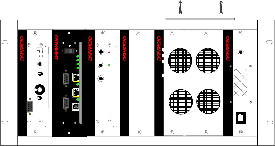
2.3 Front View
Model using Amplifier Technologies Inc power amplifier.
Figure 1 - Typical rack-mount multi-modules "Radio Assembly"
® ® ®
Exciter
Carrier On
Line
Sensitivity
Supply
Microphone
®
Diversity
SDR Rx
LOCK
RCVR
GATE
LEVEL
Volume
COM
2
Norm -Mon
® ®
Speaker Panel
programming
port
RX2RX1
OFF
SPEAKER
SELECT SWITCH
Air Flow
Power Supply Power Supply
PWR
1
12
®
PWR
TX
BSC
ETH 2
RX
USB
ETH 1
COM 2
COM 1
STATUS
120 20191-100a Paragon-III User Manual
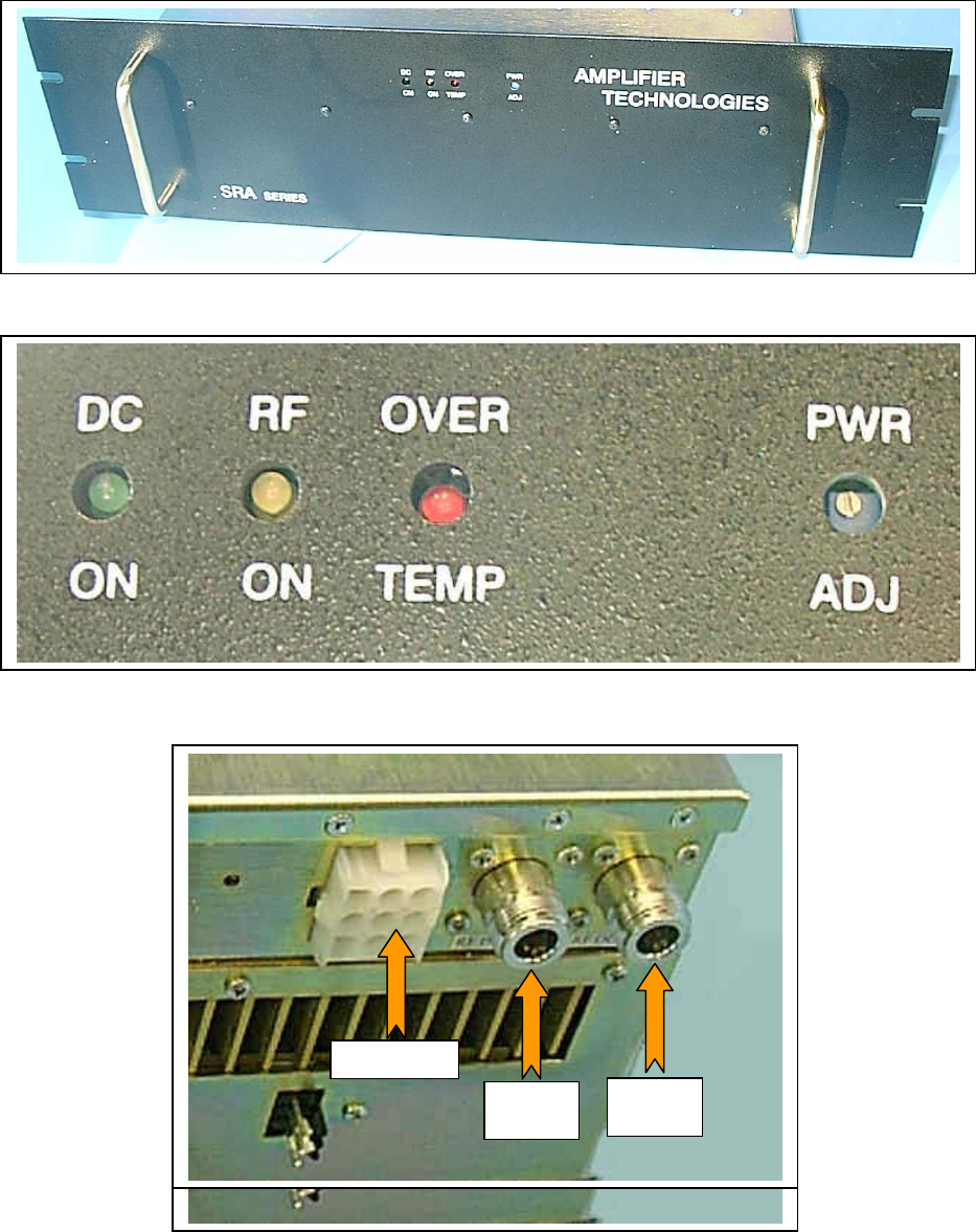
6
Figure 2 – Amplifier Technologies Inc 70W Power Amplifier
Figure 3 - Indicators and Power Adjustment Control
Figure 4 – Power Amplifier’s DC Power and RF Connectors
DC Power
RF
Input
RF
Output
DC Power
RF
Input
RF
Output
120 20191-100a Paragon-III User Manual
7
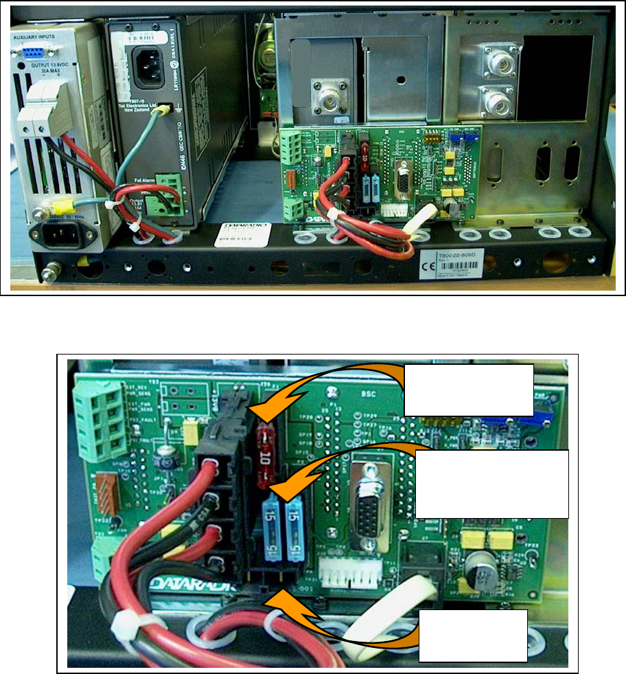
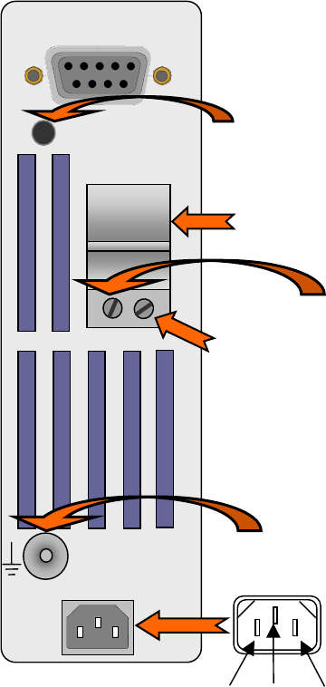
2.4 Rear Views
Figure 5 - Paragon-III rear view
Figure 6 - Backplane
Power Supply
connection to
Power Amplifier
10-amp fuse
Paragon III (minus
Power Amp)
2 x 15-amp fuses
in parallel for Power Amp
alone.
Always replace as a pair
120 20191-100a Paragon-III User Manual
8
2.5 Electrical
Standard 120 VAC electrical power is required. It should be capable of providing at least 10A to power
Paragon-III (<6A) and ancillary equipment.
2.5.1 Paragon-III Assembly Power
Two distinct power configurations (rear views) are shown in the preceding pages. They are:
• Paragon-III Base Station Standard Assembly.
This configuration is described in paragraph 2.5.1.1 below.
• Paragon-III Base Station Assy. with 3rd party DC supply.
This configuration illustrates typical wiring variation required when using both a third-party
power supply and an optional DC-powered BSC setup. Refer to Dataradio System Engineering
for further details.
2.5.1.1 Standard Power Supply Configuration
The Radio assembly unit receives 13.8 VDC power inputs from two “T809 ” power supply modules
powered at 120 VAC. Normally used at room ambient temperatures, it can operate within its specifi-
cations over a range of –10 to +60 °C.
Note: Internal over-temperature protection shuts down the main transformer above 105 degrees Celsius.
Both power supply modules are internally connected to ground via their individual, rear-connected,
seven-foot standard 120 VAC power cords. The Radio Assembly chassis requires a secure ground
connection. A threaded grounding binding post fitted with a knurled binding-nut is provided on the
chassis next to DC input 2.
• For the Radio Assembly chassis, install the grounding lead’s lug over the binding post and firmly
hand-tighten the binding-nut.
• If a –DC rail (0V) is installed as part of the system, the grounding leads may alternatively be fit-
ted to the rail terminal.
Caution:
Improper grounding between power supply case and rack frame may result in harmful voltage potentials
and/or miscellaneous power supply switching noise problems in both receivers and transmitter.
2.5.1.1.1 DC Power Supply Connection & Torque Settings
Warning: Securing the DC Power Supply cable into the DC connector to provide a good electrical
connection is essential. Over time, the wires tend to compress in the DC connector re-
sulting in an increasingly poorer connection. Consequently, as high current is drawn, the
connector heats up increasing the resistance thereby causing still more heat until the
connector eventually burns up.
Although screws securing DC cables to the Power Supply terminals are tightened to the torque set-
tings given below prior to new system delivery, they must be re-tightened as part of the commission-
ing process and re-tightening is also part of the regular maintenance schedule.
Prior to replacing a Power Supply module into an existing system, inspect the cable and re-terminate
the DC wires if the strands have previously been twisted together or show any sign of damage.
Cut the wire at the end of the insulation and then strip approximately .43 inch (11mm) of insula-
tion off the cable. DO NOT TWIST THE WIRE STRANDS. Insert the DC cable into the screw
terminal and tighten the screw to secure the cable as per the torque settings given below.
120 20191-100a Paragon-III User Manual
9
Torque Settings:
The manufacturer recommends torque setting all power supply terminal screws to a minimum of:
• 1.5 Nm (or 13.28 In/lb or to 1.107 ft/lb)
Note: Dataradio uses a Sturtuvan Richmond 29-pieces adjustable torque screwdriver model
CAL36/4K.
After tightening, pull on the cable to check the cable is secured tightly into the screw terminal.
2.5.1.1.2 Power Indications
Both red-colored translucent power switches located on the front of the power supply modules illu-
minate when AC power is available. Toggle both to ON to distribute power to the Radio Assembly
and to the Power Amplifier. The LED immediately below the switches light green indicating normal
DC power operation.
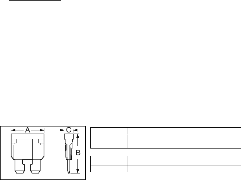
2.5.1.2 Backplane Fuses
Blade fuses (Maxi-Fuse) are used on the Radio assembly backplane (see Figure 7):
Dimensions – Inch (mm)
Fuse Type A B C
Maxi-Fuse 1.15 (29.21) 1.35 (34.29) .35 (8.89)
Fuse # F1 F2 F3
Values 10A 15A* 15A*
* Always replace the two 15A fuses as a pair.
Figure 7 - Maxi-Fuse
2.6 Power Amplifier
Although the T809-10 is a high efficiency switched mode power supply, a considerable amount
of heat is generated during normal operation. While in use, ensure that an adequate flow of
cooling air is able to circulate around the power supply, and that the air intake vents on the rear
and sides of the unit are not inadvertently covered.
Caution:
Do not operate this unit in a completely enclosed cabinet.
Refer to Figure 4 on page 6 for the location of DC power and RF in and out connectors.
Connect the T881 Tx module output to the power amplifier’s input using the Dataradio (p/n 727
03468-001) RG223 provided cable.
For the power amplifier output, Dataradio recommends a 50-ohm, low-loss, double-shielded
grade RF cable such as RG214 or 1/4" Heliax.
Power adjustments can be made using the front panel trim potentiometer. Dataradio does not
recommend setting an output lower than 35 watts.
120 20191-100a Paragon-III User Manual
10
2.7 Antenna
2.7.1 Overview
Paragon-III commonly uses three antennas (one transmit and two receive) unless a duplexer is used
with one of the receive antennas; then only two antennas would be needed. They should be mounted
according to any guidelines supplied with the antennas. For antennas placement and spacing, consult
System Engineering.
2.7.2 Cabling and Connection
1- Route good quality 50-ohm double-shielded coaxial cable(s) (e.g. RG-214 or Heliax) from the
selected antenna position(s) to the Paragon-III Radio assembly.
2- Terminate the RX-1 (top) and RX-2 (bottom) cable-ends at the SDR module rear position with N-
type connectors.
3- Similarly, terminate the TX cable-end at the Power Amp’s module rear position with an N-type
connector.
Caution:
When terminating RF cables use brand-name crimping tools (such as AMP, Jensen,
Crimp-Master, etc…) of the correct size for the cable and type of connector used.
Common pliers are NOT acceptable.
2.8 Completing the physical Installation.
Paragon-III products are factory-configured to user’s requirements and are shipped ready to run.
After new installations:
• Re-check that all connections are secure on the radio-modem assemblies (antennas, PC, power
cords etc.)
• Check that fuses are inserted.
• Turn power supplies ON.
You are now ready to check for normal operation (as per paragraph 2.9) and to run the Dataradio
CDip program for testing or trouble-shooting.
Any change(s) to the settings must be done via files saved on diskette and loaded into the unit using
the CDip program.
2.9 Checking out Normal Operation
1- Check that power is applied.
2- Check Radio assembly lights for proper operation as per section 3.1.1
3- Check for proper operation of the BSCs LEDs.
4- Using the CDip program and an in-line wattmeter, check forward & reverse power to confirm
main antenna installation
5- Using CDip, check the RF Data Link with a mobile that can be heard (as per section 5.3.1)
If user application and mobiles are available, test the installation by going through a normal sequence
of transmitting and receiving messages.
120 20191-100a Paragon-III User Manual
11
3. Operating Description
3.1 Radio Assembly
The Radio assembly component of each Paragon product is made up of high performance synthesized
radio base station designed for single operation. The Radio Assembly’s modules are commonly
installed in a standard, 19-inch wide rack frame.
The complement of modules is:
• 1 x SDR module
• 1 x 5W Transmitter
• 1 x BSC (controller-modem)
• 1 x Speaker panel
• 2 x Power Supplies
• 1 x 70-Watt Power Amplifier rackmount assembly
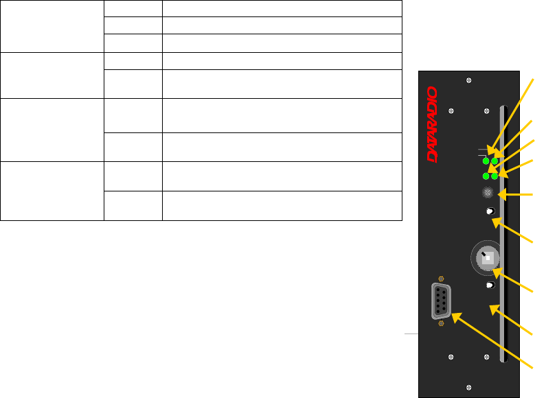
3.1.1 Diversity SDR Rx module
The Diversity SDR Rx module front panel controls and indicators are:
Green normal operation
Amber bootloader program running
PWR LED
Red malfunction / reset
Green PLL locked
LOCK LED Red PLL not locked
Green RF carrier signal on audio channel 1 is
above manually adjusted mute threshold
1 LED Off RF carrier signal on audio channel 1 is
below manually adjusted mute threshold
Green RF carrier signal on audio channel 2 is
above manually adjusted mute threshold
2 LED Off RF carrier signal on audio channel 2 is
below manually adjusted mute threshold
• RCVR GATE LEVEL - Mute threshold adjustment.
• 1 / 2 Switch – Manual selection of Channel 1 or 2 audio.
• Monitor Volume – Audio level adjustment. Always set vol-
ume knob to minimum when not in use.
• NORM-MON Switch – Manual selection between audio un-
muted (continuous monitor) or when audio is above the manu-
ally adjusted mute threshold.
• COM – For factory use.
Figure 8 - Receiver module
PWR
RCVR
GATE
LEVEL
1 – 2
Switch
Monitor
Volume
NORM-MON
Switch
LOCK
1
2
COM
®
Diversity
SDR Rx
RCVR
GATE
LEVEL
LOCK
PWR
12
21
VOLUME
NORM - MON
COM
120 20191-100a Paragon-III User Manual
12
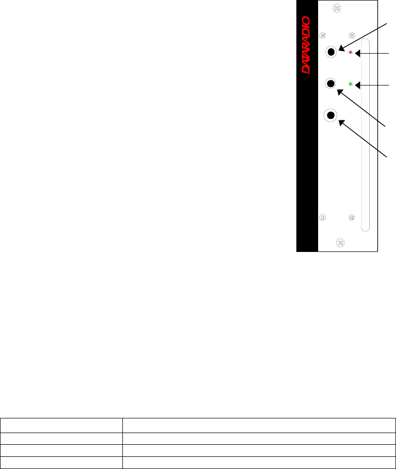
3.1.2 5W Transmitter module
The Exciter’s front panel controls and indicators are:
• Carrier Switch - momentarily keys the transmitter ON while
pressed (used for test purposes only).
• On LED - is lit when transmitting
• Line Sensitivity – not used.
• Supply LED - is lit when DC power is applied. Fast Flashes
when linked with PGM800Win. Slow Flashes indicates VCO
(synthesizer) out of lock. Unequal Flashes indicates internal
communication error.
• Microphone Socket – not used.
F
Figure 9 – 5W Exciter module
3.1.3 70W Power Amplifier
The power amplifier is maintenance free, only LED indications and a front panel adjustment are
provided for the user.
Refer to Figure 3 on page 6 above, for the locations of the indicators and the power adjustment.
Table 2 - 70W Power Amplifier indicators
LED Function
DC / ON Lights green when power is applied
RF / ON Lights yellow when input RF power is applied
OVER / TEMP Lights red when temperature-based shutdown is triggered
Carrier
Switch
On
LED
Supply
LED
Line
Sensitivity
Microphone
Socket
®
Exciter
Carrier On
Line
Sensi tivity
Supply
Microphone
120 20191-100a Paragon-III User Manual
13
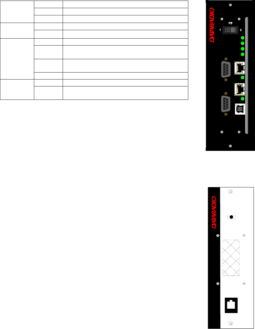
3.1.4 BSC module
The BSC's front panel connectors and indicators are:
Green Normal operation
Amber Step 2 in uMon boot-up – lights for <1 sec.
PWR LED
Red Step 1 in uMon boot-up – lights for <1 sec.
Green Flashes for each data packets received
RX LED Red Discard RX packet (factory-use)
Green Flashes for each data packets transmitted
Amber Flashes for each data packets transmitted
(check for lost Host connection)
Red Continuoulsy ON for TXON test (max. 20 secs.)
Flashes ON for CWID key-up event
TX LED
Off Check if in “AirLink down mode”
Green Flashes each time PF1 or PF2 is pressed
STATUS Amber Flashes each second PF1 is kept pressed
Toggles “AirLink down mode” after 4 seconds
• 2x DE-9 RS-232 ports for setup and user data
• 1X rocker switch ( positions PF 1 and 2) to select various test modes
• 2x Ethernet ports – for setup and user data
• 2x Ethernet LEDs (status & activity)
• USB port – reserved.
Figure 10 - BSC module
3.1.5 Speaker panel
The speaker panel is fitted with a four-Ω
speaker.
All series of radio assemblies share the same front
panel fitted with an RJ11 connector. This connector
is used to allow programming the radio transmitter
module (only) from the front of the unit via a pro-
gramming lead. This feature is exclusive to the Se-
ries II and Paragon III modules.
If the speaker panel needs to be removed, a mirror
programming port connector is provided on the
backplane.
Figure 11 - Speaker module
®
Speaker Panel
programming
port
RX2RX1
OFF
SPEAKER
SELECT SWITCH
®
PWR
TX
BSC
ETH 2
RX
USB
ETH 1
COM 2
COM 1
STATUS
120 20191-100a Paragon-III User Manual
14
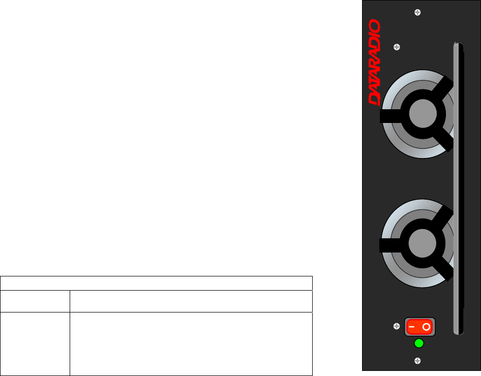
3.1.6 Power Supply Modules
Two switched mode pulse width modulated T-809 power supply modules are
used but not connected in parallel.
Both power supply units have ON-OFF control and remote sensing via a rear
mounted DE-9 connector, and an output voltage adjust potentiometer (13.5
to 18 VDC).
Their circuit protection features are:
• Inrush current limiting
• Over-current (short-circuit)
- 37 to 48A constant current limiting
- Reset = auto recovery
• Over-voltage
- 18 to 21 VDC = shutdown
- Reset = Power OFF and ON
• Over-temperature
- shutdown of output voltage
- auto recovery with temperature reduction
- temperature sensed on transistors and diodes
Front Panel Indications
Power Switch Illuminates when the unit is connected to AC power and
voltage is available
ON LED - Lights bright green when voltage output is normal
- Lights faint green when module has entered over-
current mode
- Green LED is OFF, but power switch is ON indicates
module has shut down due to over-temperature or over-
voltage conditions.
Figure 12 - T-809 Power Supply Module
®
Power Supply
Power
On
120 20191-100a Paragon-III User Manual
15
3.1.6.1 Power Supply Rear Connections
The rear panel connections are:
• Auxiliary Inputs –
The DE-9 connector on the T809-10 rear panel
provides access to the remote control and remote
sense functions of the power supply.
• Output Voltage Adjust –
The output voltage of the power supply can be in-
creased (up to 18V approximately) to compensate
for the voltage drop lost along the cable. Access the
trim-pot through a small hole on the rear panel.
To adjust the output voltage use a trimmer tool with
a Phillips head or 3mm blade (do not use a stan-
dard flat blade screwdriver to make the adjust-
ment):
• To increase the output voltage, turn the trim-
pot clockwise.
• To decrease the output voltage, turn the trim-
pot counterclockwise.
If the output voltage is increased on a power supply
operating at, or close to, full load, the power supply
loading must be reduced accordingly or the module
may overheat and shut down.
• Feedthrough Terminal Block –
The DC Output Terminal block on the rear of the
T809-10 is a Phoenix Contact HDFKV 10. This is a
screw-type terminal connector that uses a cage
mechanism to clamp the conductor(s). See section
2.5.1.1.1 for recommended torque settings.
Figure 13 - T809 Rear panel
• Protective Bonding Terminal –
The Radio Assembly requires a secure ground connection. See section 2.5.1.1 for connection details.
• 120 VAC Connector –
Use the supplied 10A-rated IEC type power cord.
AUXILIARY INPUTS
OUTPUT 13.8 VDC
30A MAX
- +
- +
100-240 VAC 50/60Hz
1
9
Output voltage adjust
Feedthrough terminal
block
13.8 VDC output
Negative (-)
Positive (+)
Protective
bonding
terminal
NeutralLive Earth
120 20191-100a Paragon-III User Manual
16
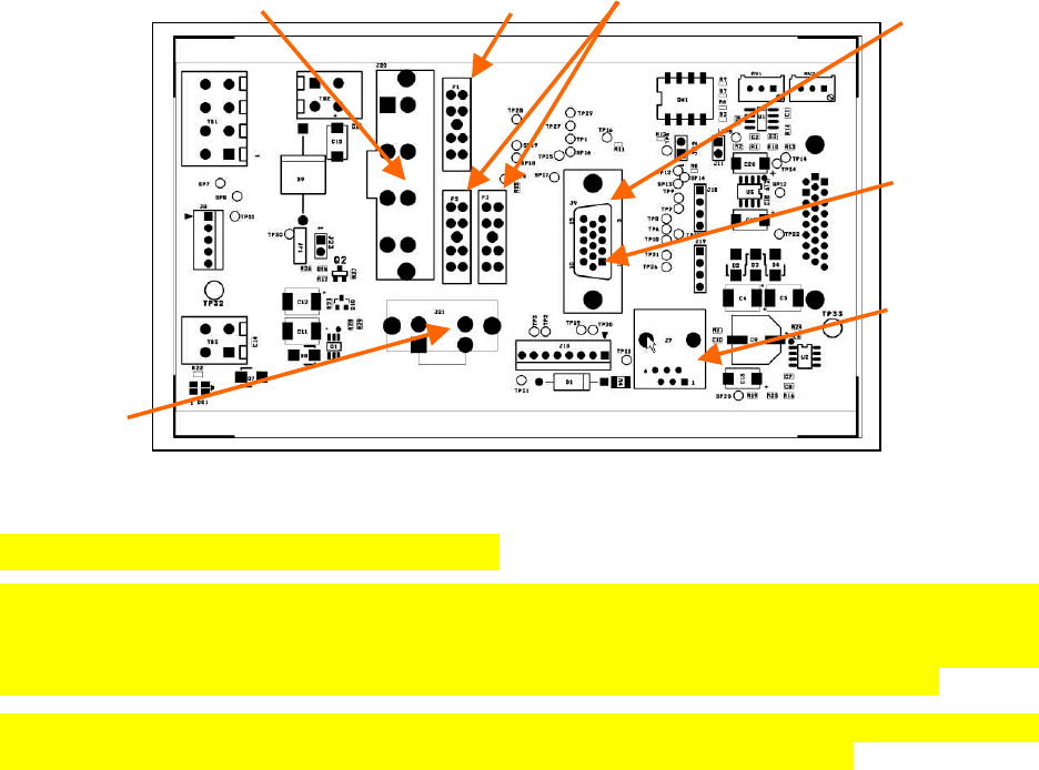
3.1.7 Radio Backplane Assembly
Figure 14 - Radio Backplane Assembly
3.2 Online & Offline Diagnostics
Paragon-III units continually monitor and report on their environmental and operating conditions. Each
transmission carries online diagnostic information which can be monitored remotely or even sent to a
designated host for logging and later analysis. Transmission of online diagnostics may be enabled or dis-
abled at any station or stations without affecting their ability to communicate with other stations
Additional information, statistics, and offline test facilities are available via the browser. RF paths can be
monitored and checked from either end of a link, without travelling to the other station.
Power Amplifier
13.8 VDC
Maxi-Fuse 10A 2 Maxi-Fuses 15A DE-9 for Remote control or
remote sense functions
RJ-45 connector
Used for
programming
System 13.8 VDC
Pin 1
F1
F3
F2
120 20191-100a Paragon-III User Manual
17
4. Operation & Configuration
4.1 Browser-Based Setup and Status
A built-in web server makes configuration and status monitoring possible from any browser-equipped
computer, both locally or remotely. Status, configuration, and online help are available without requiring
special client software. Setup is password-protected to avoid tampering or unauthorized changes.
Both the configuration parameters and operating firmware can be updated remotely, even over the RF
network itself, using the standard FTP protocol.
4.2 Default IP Settings
• Paragon-III radio modem supports the Router (IP Forwarding) mode
4.2.1 Ethernet Interface 1 (DATA)
• MAC: 00:0A:99:XX:YY:ZZ
• IP ADDR: 192.168.202.1
• NETMASKS: 255.255.255.0
• Default Gateway: 0.0.0.0
• DHCP Server Disabled
• RIPv2 Disabled
4.2.2 Ethernet Interface 2 (SETUP)
• MAC: 00:0A:99:XX:YY:ZZ + 1
• IP ADDR: 192.168.203.1
• NETMASKS: 255.255.255.0
• DHCP Server Disabled
• NAT Disabled
4.2.3 RF Interface
• MAC: 00:XX:YY:ZZ
• IP ADDR: 10.XX:YY:ZZ
• NETMASK: 255.0.0.0
• Compression Enabled
• Encryption Disabled
120 20191-100a Paragon-III User Manual
18
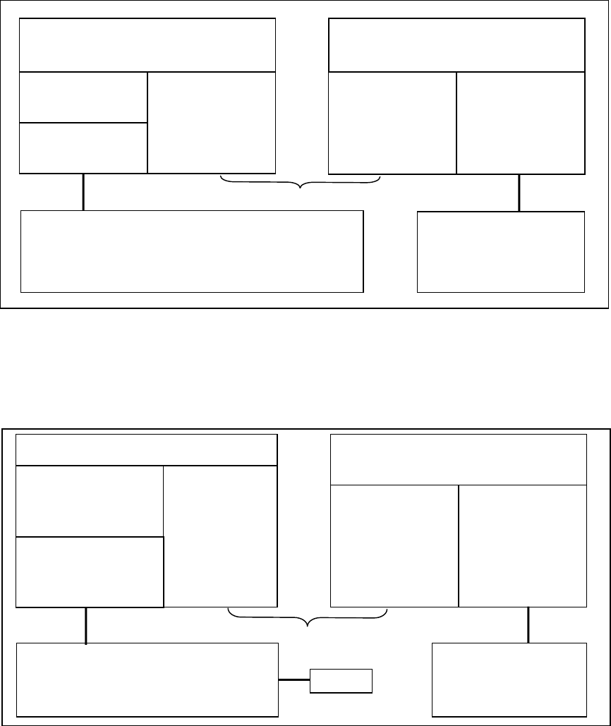
4.3 IP Network Settings
4.3.1 IP Network Settings (with Host)
Referring to Figure 15 below, set the Paragon-III base station. Set the “Data” port Eth1 IP addresses (for
“Setup” port set Eth2) and IP netmask of both Base and Mobile(s).
Keep the RF IP setting as is, providing customer is not using the 10.0.0.0 IP network.
Add routes in the Host (route add…)
In the illustration, Host and PC are part of different IP subnet.
Figure 15 - IP Network Settings in Router Mode (with Host)
4.3.2 IP Network Settings (with Router)
Referring to Figure 19 below, set the Paragon-III base station. Set the “Data” port Eth1 IP addresses (for
“Setup” port set Eth2) and IP netmask of both Base and Mobile(s).
Figure 16 - IP Network Settings in Router Mode (with Router)
Paragon-III Base
DATA:
Eth1 IP: 192.168.202.1
MASK: 255.255.255.0 RF IP: 10.0.0.1
MASK: 255.0.0.0
Mobile
DHCP Server
RF IP: 10.0.0.2
MASK: 255.0.0.0 Eth1 IP: 192.168.201.1
MASK: 255.255.255.0
RF Network
Host
IP: 192.168.202.2
MASK: 255.255.255.0
route add 192.168.201.0 mask 255. 255. 255.0 192.168.202.1
route add 10.0.0.0 mask 255.0.0.0 192.168.202.1
PC
DHCP Client
SETUP:
Eth2 IP: 192.168.203.1
MASK: 255.255.255.0
Paragon-III Base
DATA:
Eth1 IP: 192.168.202.1
MASK: 255.255.255.0
Gateway: 192.168.202.2 RF IP: 10.0.0.1
MASK: 255.0.0.0
Mobile
DHCP Server
NAT
RF IP: 10.0.0.2
MASK: 255.0.0.0 Eth1 IP: 192.168.201.1
MASK: 255.255.255.0
RF Network
Router
IP: 192.168.202.2
MASK: 255.255.255.0
route add 10.0.0.0 mask 255.0.0.0 192.168.202.1
PC
DHCP Client
SETUP:
Eth1 IP: 192.168.203.1
MASK: 255.255.255.0
Gateway: 192.168.202.2
Host
120 20191-100a Paragon-III User Manual
19
Keep the RF IP setting as is, providing customer is not using the 10.0.0.0 IP network.
Enable RIPv2 on Base station
In the illustration, Host and PC are part of different IP subnet.
4.4 LAN Setup
On a PC running MS-Windows with an existing LAN connection, connect either to the ETH1 (Data) or to
ETH2 (Setup) RJ-45 input of the Paragon-III.
1. Click Start Î Settings Î Control Panel Î Network and Dial-up Connection
2. Click on the relevant Local Area Connection
3. On the Local Area Connection Status screen, click Properties
4. On the Local Area Connection Properties screen, scroll the List Box until “Internet Protocol
(TCP/IP)” is highlighted, click Properties
5. On the Internet Protocol (TCP/IP) Properties screen, follow either method below:
A) Select “Obtain an IP address automatically”
B) Select “Use the following IP address” Î Enter 192.168.202.2 (if ETH2 enter 192.168.203.2) in
the IP address field Î 255.255.255.0 in the Subnet mask ÎLeave the Default gateway blank.
6. Click the OK button
Note: On computers running Windows 9X, reboot to complete the connection process.
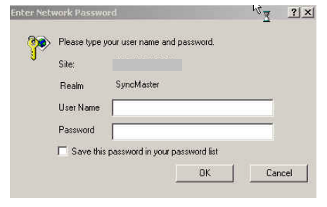
4.5 Login Screen
On the Address line of the Internet browser of your choice, type the factory-default IP addresses given to
all Paragon-III radiomodem units: 192.168.20x.1 (where x is 2 for the ETH1 Data port and 3 for the
ETH2 Setup port). Press Enter. The Enter Network Password screen opens.
Figure 17 - Enter Network Password screen – ETH1 Data port shown
4.5.1 Initial Installation Login
For an initial installation, enter a User Name 1 to 15 characters and a Password 8 to 15 characters. Do not
place a check mark in the “Save this password in your password list” box. Click OK to access the Web
Interface (Figure 18).
Dataradio recommends to immediately change the Paragon-III unit’s IP address as well as set your own
login password as part of the initial configuration (See 4.7.2.2 and 4.7.2.10).
For subsequent access to the Paragon-III unit, use the User Name and Password you configured.
Note:
The User Name entry is currently not an access-limiting factor. It only serves to identify the per-
son gaining access. User Name may be required by future versions.
192.168.202.1
120 20191-100a Paragon-III User Manual
20
4.6 Security Setup
1. Navigate the web interface to the “Security” menu.
• Set User ID (optional in a basic setup)
• Set Password (optional in a basic setup)
• At Encryption, click the Enabled button
• Enter Encryption Key
2. Click Apply Parameters
3. Click Save Parameters
4.7 Interface
The Paragon-III user interface (Figure 18) provides easy access to the various menus used to configure
and view your network settings.
The Navigation Area lists seven top-level menus, four of which expand to offer submenu. The tables
starting at section 4.7.2 below list action of each function.
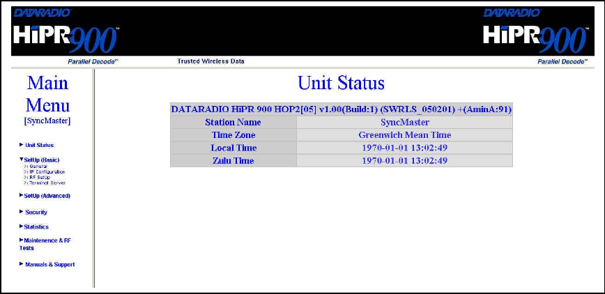
Figure 18 - Web User Interface (Preliminary – HiPR-900 model shown)
120 20191-100a Paragon-III User Manual
21
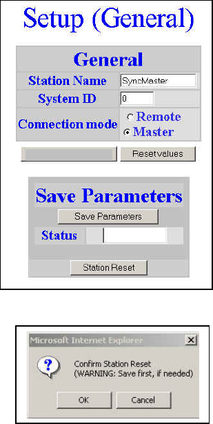
4.7.1 Apply Parameters & Save Parameters Buttons Behavior
Submenus which have Dialog boxes also have Command Buttons to Apply, Reset, and Save Parameters
in addition to Station Reset.
Referring to the example in Figure 19 below, make entries into the Dialog boxes. When satisfied, click on
Apply Parameters to temporarily make the parameters active. If not satisfied, click on Reset values button
to restore to the values present before changes were made.
Notes:
Reset values commands affect all Dialog boxes or radio buttons only in the opened window.
If needed, go to other Submenu(s) and make more entries. Click Apply Parameters before leaving each
window. When finished, click a Save Parameters button in any of the Submenus to make changed entries
permanent (along with any other entries made in other submenus).
The Station Reset command button only appears when a parameter requires a Station Reset, otherwise it
is unavailable. Use the Save Parameters command button before Station Reset otherwise temporarily en-
tered parameters are lost. Pressing the Station Reset button opens the Confirm Station Reset (Figure 20)
as a reminder to first save.
Figure 19 - Parameter Command Buttons behavior
Figure 20 - Station Reset Confirmation
Apply Parameters

120 20191-100a Paragon-III User Manual
22
4.7.2 Unit Status
Table 3 - Unit Status
Item Description
Banner Displays Paragon-III information retrieved from the connected unit.
Have this information handy if contacting Dataradio support.
Station Name Displays name of connected unit.
Configured under Setup Basic Î General Î StationID
Time Zone Displays local time zone.
Configured under Setup Advanced Î SNTPÎ TimeZone
Local Time Displays local time computed using UTC time and Time Zone
Zulu Time Displays UTC time.
Configured under Setup Advanced Î SNTPÎ SNTP UTC Time
4.7.2.1 Setup (General)
Table 4 - Setup (General)
Item Description
Station Name Station name identifier – Enter string up to forty characters in length
Connection mode Mobile/Base
IP Forwarding mode Router mode –
4.7.2.2 Basic IP Configuration
Table 5 - Basic IP Configuration
Item Description
IP Address Set to valid unique IP address for each individual unit
Network Mask Set to valid IP netmask for each individual unit (may be same or differ-
ent depending on customer’s IP network topology).
IP Default Gateway Set to valid Default Gateway.
May change for different groups or locations
4.7.2.3 RF Setup
Table 6 - RF Setup
Item Description
Power Level Sets power level between 0.1 and 1.0 watt (Default 1.0)
Airlink speed 256000, 512000 (Default) - Sets the maximum speed the HiPR900 will
use for data packet transmissions. Slower speed preferred for longer
range.
SubBand Mask Indicates which channels are to be used in the shared band.
4.7.2.4 Terminal Server Configuration
Table 7 - Terminal Server Configuration
Item Description
Port 1 - 2400, 4800, 9600, 19200, 38400, 57600, 115200
Baud Rate Port 2 - 2400, 4800, 9600, 19200, 38400, 57600, 115200
Port 1 - Inactive, TCP Passive, TCP Active, UDP
Connection Mode Port 2 - Inactive, TCP Passive, TCP Active, UDP
Local IP Address
Valid unicast or multicast IP address, including the local Loopback
interface address.
Default local IP address is set to 0.0.0.0 and can be changed dynami-
cally without a unit reset.

120 20191-100a Paragon-III User Manual
23
Local Port
For TCP active and UDP socket connections, set to any values between
1 and 65536.
For TCP passive socket connections, set to any value between 1 and
65536 but must not be set to one of the following values or fall within
the following ranges of values: 20, 21, 23, 123, 520, 5002, 6254 to 6299,
7000 to 7100. Otherwise, the parameter configuration will be accepted,
but no socket connection will be established to accept connection from
remote endpoints.
Default local port value is set to 1024 and can be changed dynamically
without a unit reset.
Remote IP Address Default remote IP address is the Loopback interface address, 127.0.0.1
and can be changed dynamically without a unit reset
Remote Port
For all socket connection modes (TCP passive, TCP active, UDP), set to
any value between 1 and 65536.
Default local port value is 23 and can be changed dynamically.
4.7.2.5 Advanced IP Configuration
Table 8 - Advanced IP Configuration
Item Description
MTU Ethernet Interface 1 IP MTU - Default 1500. Range 576 to 1500 bytes
Factory MAC address Ethernet Interface 1 factory (Dataradio) MAC address in HEX format
DHCP Server Disabled, Enabled (Default). Ethernet Interface 2
DHCP Client Disabled(Default), Enabled. Ethernet Interface 1
NAT Disabled(Default), Enabled. Ethernet Interface 2
RIPV2 Disabled(Default), Enabled,
4.7.2.6 RF Network Setup
Table 9 - RF Network Setup
Item Description
RF MAC Unit’s RF MAC address
Displays factory-assigned address: nnn.nnn.nnn.nnn “Factory”
RF IP Address Entering 0.0.0.0 sets the RF IP Address to the factory default and high-
lights the “Factory” name (active address)
Entering nnn.nnn.nnn.nnn (RF IP Address of your choice) overrides the
factory default and highlights the “Override” name (active address)
RF Net Mask Set to valid common IP netmask for all units within a HiPR network
RF MTU Default 1500. Range 576 to 1500 bytes
4.7.2.7 Broadcast / Multicast
Table 10 - Broadcast / Multicast
Item Description
Broadcast Outbound mobile address
Broadcast Directed Enable Disabled, Enabled
Broadcast Limited Enable Disabled, Enabled
Multicast Addresses
Multicast Add / Delete Address Add, Delete and Relevant address
Multicast Enable Disabled, Enabled

120 20191-100a Paragon-III User Manual
24
4.7.2.8 IP Optimization & Tuning
Table 11 - IP Optimization & Tuning
Item Description
Optimization Data Compression Disabled, Enabled (Default). Applies data compression over the IP pay-
load
OIP RF ACK enable Disabled (Default), Enabled.
OIP Retries Enter number of retries. Default is 3, range 0-255
4.7.2.9 Simple Network Time Protocol
Table 12 - Simple Network Time Protocol
Item Description
SNTP – Server addr
SNTP – Enable Disabled, Enabled
SNTP – Period
SNTP – UTC Time
SNTP – TimeZone
SNTP – Daylight Savings Off, On
Time Control – Time Sources AirLink, SNTP
Time Control Refresh Period
Time Control Refresh TimeOut
4.7.2.10 Security
Table 13 - Security
Item Description
User ID Enter a string of any letters or numbers of at least 1 and not exceeding
15 characters
Old Password For initial installation, enter a string of any letters or numbers of at least
8 and not exceeding 15 characters. For subsequent access, enter the
old password.
New Password Enter a string of any letters or numbers of at least 8 and not exceeding
15 characters
New Password Re-enter the new password string
Encryption Disabled, Enabled
Encryption Key
All units in a network must have the same key. Enter a string of 32
(16bytes = 128 bits) hexadecimal characters (0 to F).
Displayed in pairs separated with spaces
4.7.2.11 Network Statistics
Table 14 - Network
Item Description
Data bytes presented
Control Acks Rx’d
Data packets sent
Data bytes delivered
Control Nacks Rx’d
Data packets Rx’d
120 20191-100a Paragon-III User Manual
25
4.7.2.12 Packet Statistics
Table 15 - Packet Statistics
Item Description
Total RX packets
Total TX packets
IP
Stats Total Packets Forwarded
Total RX packets
UDP
Stats Total TX packets
Total RX packets
Eth 1
Stats Total TX packets
Total RX packets
ICMP
Stats Total TX packets
Total RX packets
TCP
Stats Total TX packets
Total RX packets
Eth 1
ARP
Stats Total TX packets
4.7.2.13 RF Test
Table 16 - RF Test
Item Description
Ping
Test Tones
4.7.2.14 FTP Transfer
Table 17 - FTP Transfer
Item Description
Server Address
User Name
Password
File Name
Operation Send (Put), Receive (Get)
Mode ASCII, Binary
Request Transfer
Reset values
Status
4.7.2.15 RSSI Table
Table 18 - RSSI Table
Item Description
RSSI Table RSSI Table illustration, see figure nn
4.7.2.16 Support
Table 19 - Manuals & Support
Item Description
Support Show link(s)

120 20191-100a Paragon-III User Manual
2
6
5. Trouble-Shooting and Testing
The checks described below should be done at time of installation, annual intervals, or whenever de-
terioration in performance is noted.
5.1 Equipment Required
• In-line watt meter (10 W range) for the 5W transmitter module and for reflected power and
(100W range) for the power amplifier.
• Radio service monitor (IFR-120B with option 03: 30KHz IF filter or equivalent).
• RG-214 or RG-223 cable with N-Type male connector to connect Paragon-III to the service
monitor.
• CDip 1.0 or later1
Important note: Before proceeding make sure that the service monitor has been calibrated recently
and has warmed up for at least the time specified by its manufacturer.
Some reported frequency and deviation problems have actually been erroneous indications from
service monitors that have not adequately warmed up. This is particularly likely when field service is
done during winter months.
5.2 Recommended Checks
A) After an installation
1. LED Indications
2. Using CDip, Save “unit config” to a file
3. Transmitter Output Power
4. Transmitter Reflected Power
5. RF Link test between Paragon-III and mobile unit(s)
B) For annual maintenance & trouble-shooting
Same checks as A) plus:
6. Carrier Frequency Error
7. TX Deviation
8. 12 dB SINAD
9. Receiver distortion
10. RSSI check
11. Verify power supply connections & terminals torque settings (see paragraph 2.5.1.1.1)
1 To learn how to launch the Windows-based software alignment and system-testing tool CDip, please refer to
the readme.txt file on the application’s installation diskette.
For functional details of the numerous buttons and menu-selectable items available, please refer to the program’s
context sensitive help. It is also possible to access the help information via the F1 key.

120 20191-100a Paragon-III User Manual
2
7
Table 20 - Checklist A (After installation)
CHECKLIST A
(Paragon-III)
Recommended Check out after Installation
Step ACTION EXPECTED RESULTS
at 25°CMEASURE WITH IF NOT?
1Normal Power-up
Sequence PWR LED lights red for one second, turns amber for one second, and stays
green thereafter.
TX LED flashes green once about eight seconds after power-up then keeps
flashing in-tune to the cycle marker
RX and STATUS LEDs remain OFF
2Connect and save unit
config
Press CDip Get button
as per CDip Help content
3Power Amplifier Output
Power
Press TXON (Unmod)
70 watts
±10%
Service monitor set
to read power
or
100W in-line watt-
meter installed as
close as possible to
the unit antenna
connector.
Check for bad connections,
damaged coax cable, etc.
4Transmitter Reflected
Power
Press TXON (Unmod)
< 5% of forward power or
as specified by System
Engineering.
10W in-line wattme-
ter Check for bad connections,
damaged coax cable, etc.
5RF Link test
Use the mobile address
function and “Send” but-
ton to dynamically test
the link
Look for
“Delivery confirmed” on
the Status bar
Refer to 5.3.1 and to
CDip Help content.
Mobile is out of range
Refer to factory technical
support.

120 20191-100a Paragon-III User Manual
28
Table 21 - Checklist B (General)
CHECKLIST B (Paragon-III)
General Check out (part1 of 2)
Paragon-III units are set and characterized at the factory to optimize performances.
It is not recommended to try readjusting units unless it is really required.
Misadjusting a unit may result in significant performance losses.
The proposed adjustments in the "IF NOT?" column below, should be tried ONLY if system data
performance degradation is noticed combined with out-of-tolerance items.
Step ACTION Expected Results at 25°CMEASURE WITH IF NOT?
1Normal Power-up
Sequence PWR LED lights red for one second, turns amber for one second, and stays green there-
after.
TX LED flashes green once about eight seconds after power-up then keeps flashing in-
tune to the cycle marker
RX and STATUS LEDs remain OFF
2Connect and save unit
config
Press CDip Get button
as per CDip Help content
3
Transmitter Output
Power
Press TX ON (Unmod)
70 watts
±10%
Service monitor set
to read power
or
100W in-line watt-
meter installed as
close as possible to
the unit antenna
connector.
Adjust “Power” on the front
panel of the “Power Amp”
4Transmitter Reflected
Power
Press TXON (Unmod)
< 5% of forward power or as
specified by System Engi-
neering.
10 W in-line
wattmeter Check for bad connections,
damaged coax cable, etc.
5Carrier Frequency Er-
ror
Press TX (Unmod)
< ±300 Hz Service monitor set
to read frequency
error
Adjust TCXO (IC700)
(see inside Exciter module at,
Figure 24
6TX Deviation (KHz)
Press
TX (modulated)
Carrier will be modulated
with a 1 kHz tone.
±8.0 kHz
Tolerance is +5%, -10%
Service monitor set
to read deviation.
(IF filter set to Mid
or 30 kHz position) Refer to tech support
120 20191-100a Paragon-III User Manual
29
CHECKLIST B (Paragon-III)
General Check out (part2 of 2)
Paragon-III units are set and characterized at the factory to optimize performances.
It is not recommended to try readjusting units unless it is really required.
Misadjusting unit may result in significant performance losses.
The proposed adjustments in the "IF NOT?" column below, should be tried ONLY if system data
performance degradation is noticed combined with out of tolerance items.
Step ACTION EXPECTED RESULTS at
25°CMEASURE WITH IF NOT?
Set the service monitor to generate on the selected receive frequency. Verify alternately for both receivers.
The carrier should be modulated with a 1.0 kHz tone at deviation level specified below:
8
12 dB SINAD
(Dataradio wide band
measurement method: no
audio filtering)
Set deviation to ±8 kHz.
Better than -108 dBm
including cable loss
(Typically -109 to -110 dBm)
- Backplane corre-
sponding to the re-
ceiver being verified:
J1 (RX1) or J5 (RX2),
Pin 6 Service monitor
(IFR) set to SINAD
- IFR IF filter set to MID
position or 300 kHz
wide filter.
Refer to section Error!
Reference source not
found.
9
Receiver distortion
(Dataradio wide band
measurement method: no
audio filtering)
- Set service monitor RF
Gen output to –70 dBm
- Deviation level as per
SINAD above.
≤ 5.5 %
(Typically < 3.5 %)
- Backplane corre-
sponding to the re-
ceiver being verified:
J1 (RX1) or J5 (RX2),
Pin 6 Service monitor
(IFR) set to
DISTORTION.
- IFR IF filter set to MID
position or 300 kHz
wide filter.
Refer to section Error!
Reference source not
found.
10 RSSI
Apply to each receiver
input the following RF
level of -110dBm 2.0 VDC (+/- 0.3VDC)
- Backplane corre-
sponding to the re-
ceiver being verified:
J1 (RX1) or J5 (RX2),
Pin 5
- DC Voltmeter
measurement
Refer to section x for all
models.
Refer to factory technical
support only if RX data
performance degradation is
noticed combined with out
of tolerance RSSI readings.

120 20191-100a Paragon-III User Manual
30
5.3 Additional test details
5.3.1 RF Data Link Test
A link test between a mobile and a known base station can be done using the CDip "Address" and
"Send" functions. The “Address” and “Device” fields, the “Send” button and the “Chat” message screen
are used to send messages to specific mobile or base or to carry out RF test. Start by entering the ad-
dress of the mobile (or base station) you wish to send a test message to or test:
1- Specify the address:
Addresses may be entered by typing directly in the “Address” field in two ways:
- Numerically, the valid address range is 1-126.
- As an “Alpha-Mapped-Nibble” (AMN) address, consisting of upper case letters in the range A-
P.
The valid address range is A to GN.
- The base address is usually: 1.
- The program may display one of the following messages on the status bar:
- For Paragon-III products:
“address is not in AMN or number format”
- For mobile products:
“address is not in the range A – GN”
In either case, check that the address entered is within the acceptable range, is of a valid format and
correctly typed.
2- Enter the Device number for mobile (or base station).
3- Press the Send button.
The Chat window reports “Sent to xx mobile” (where xx is mobile name).
If test is successful:
Status line reports “Delivery confirmed.
If test unsuccessful:
Chat window reports “Waiting”,
Then the Status line reports “Delivery Failed”.
120 20191-100a Paragon-III User Manual
31
5.4 Windows/Unix Tools
5.4.1 Network Connectivity
• PING
The ping command determines whether a specific IP address is accessible. It works by send-
ing a packet to the specified address and waiting for a reply. It is useful for troubleshooting
“end-to-end” reachability, network connectivity, and network latency.
Available for MS-Windows 9x, ME, NT, 2000, and XP as well as Unix & Free BSD.
EXAMPLE:
ping 192.168.204.1 displays the response with turn around time in milliseconds.
• TRACERT (WINDOWS)
The tracert command is used to visually see a network packet being sent and received and
the amount of hops required for that packet to get to its destination.
Available for MS-DOS 6.2, MS-Windows 9x, ME, NT, 2000, and XP.
Note:
Users with MS-Windows 2000 or XP who need additional information on network latency
and network loss may also use the pathping command.
EXAMPLE
tracert www.yahoo.com at the command prompt displays the intermediate routers be-
tween local host to the ww.yahoo.com site.
5.4.2 Configuration Information
• WINIPCFG (WIN95/98), IPCONFIG (WIN2K) or IFCONFIG (UNIX)
Ipconfig is a DOS utility which can be used from MS-DOS or a MS-DOS shell to display
the network settings currently assigned and given by a network. This command can be utilized
to verify a network connection as well as to verify network settings.
Available for MS-DOS, MS-Windows 9x, ME, NT, 2000, and XP.
EXAMPLE
ipconfig/all at the command prompt displays the Ethernet MAC address, IP address, IP
netmask, default IP gateway, DNS server… information.
• ARP
View and update the system ARP table
The Address Resolution Protocol (ARP) is used with the IP protocol for mapping a 32-bit
Internet Protocol address to a MAC address that is recognized in the local network specified in
RFC 826. Once recognized the server or networking device returns a response containing the
required address.
Available for MS-Windows 9x, ME, NT, 2000, and XP.
EXAMPLE
arp-a displays all entries in the ARP cache. Useful in manipulating ARP caches.
• ROUTE
View and update the system routing table

120 20191-100a Paragon-III User Manual
32
The function and syntax of the Windows ROUTE command is similar to the UNIX or Linux
route command. Use the command to manually configure the routes in the routing table.
Available for MS-Windows 9x, ME, NT, 2000, and XP.
EXAMPLE
route ? displays help
route print displays the routing table
5.4.3 Statistics Information
• NETSTAT (WINS & UNIX)
The netstat command symbolically displays the contents of various network-related data struc-
tures, i.e. IP, TCP UDP …
Available for MS-Windows 9x, ME, NT, 2000, and XP.
EXAMPLE
netstat ? displays help
netstat-a display TCP and UDP connections and listening ports information
For further information on TCP/IP troubleshooting, please visit:
http://www.windowsitlibrary.com/Content/466/14/1.html

120 20191-100a Paragon-III User Manual
33
6. Radio Programming and Adjustments
6.1 T881-10 Radio Transmitter Programming
This procedure describes the steps needed to program the Paragon-III radio transmitter module.
6.1.1 Recommended Items
- 486 PC or better, MS-Windows 98 © or later
- T800win programming kit for Series II:
- PGM800Win programming software user's manual
- PGM800Win Windows based programming software version 3.0 or later
- T800-01-0002 programming cable (DB-25 to RJ-45 cable)
- Standard 25-pin parallel cable (terminated Male/Female)
6.1.2 T881-10 Module Programming
Before starting programming, have a PC running MS-Windows © and the Tait PGM800Win software
for Series II Base station.
This program supports the use of a mouse but may be used without one if required. Keyboard access
follows the conventional MS-Windows © method as briefly described below:
- Press and hold the “Alt” key while pressing at the same time the relevant hotkey as indicated by an
underlined letter on the menu command.
- On a drop-down menu, press only the hotkey without pressing the “Alt” key.
- Use the “Tab” key to cycle available fields and the “Enter” key to validate entries. E.g. Pressing
“Alt”+F opens the File drop-down menu and pressing “A” opens the Save As directory service box.
The transmitter VCO alignment will be required when new transmitter frequency is programmed
outside the radio tuning range: ± 4.0 MHz from previous center frequency. The legal
frequency ranges for this transmitter are:
762-764 MHz and 767-773 MHz. The retuning of the VCO will normally only be
required when passing from one range to the other.
1. Connect the PC, via the supplied programming lead, to the speaker panel’s front-mounted RJ11
connector.
2. Run Tait PGM800Win program and follow instructions found in the T800 Programming Soft-
ware User’s Manual to select the proper module to be programmed.
3. Program required channel's frequencies.
– Do not program any CTCSS tones on channels.
– Do not change any other parameters.
– Refer to Figure 21 and Figure 22 for screen program examples.
4. Save the base station programming info to a file for further reference.
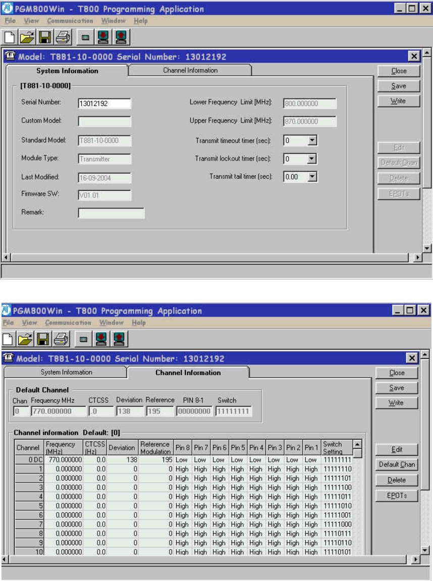
120 20191-100a Paragon-III User Manual
34
Figure 21 - Exciter System Infomation Sample
Figure 22 - Exciter Channel Information Sample
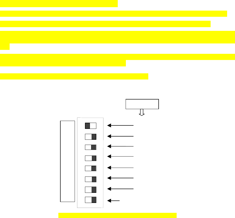
120 20191-100a Paragon-III User Manual
35
6.1.3 Channel Selection via DIP Switches
The backplane-mounted DIP switch settings override the default channel programmed by PGM800Win.
To set a default channel via the software, all DIP switches must be set to “OFF” (i.e. 00000000).
When a switch is “Off”, its binary count is active; when a switch is “ON” its binary count is inactive. The
various DIP switch combinations of ON or OFF make up a binary total, which identifies the channel num-
ber.
To select a channel, set the appropriate DIP switch or switches to “OFF” to make the binary count total the
channel number you want. Set all other switches to “ON”.
Example: To select channel 1, set the DIP switches as shown below:
Figure 23 - Backplane DIP switches example - Channel 1 selected
Binary Value
1
2
4
8
16
32
64
Always ON except when
default channel is required
CHANNEL SWITCH TX - RX
1
2
3
4
5
6
7
8
O
F
F

120 20191-100a Paragon-III User Manual
3
6
6.2 Transmitter Radio Tuning
- This section covers the basic Series II base station 700MHz transmitter radio module and PA
radio tuning and verification.
Note: Usually, this section is never done unless called for in section 6.1 “Series II - Radio Pro-
gramming” or in Table 21 - Checklist B (General)“Checklist B” (General).
6.2.1 Test Equipment
- Digital Multimeter & probes (e.g. Fluke 77)
- 1 HP 34330A Shunt 30A (UHF only, used for transmitter current measurement)
- Digital or Analog calibrated Oscilloscope & scope probes (X1, X10 selectable)
- Calibrated COM-120B (.001ppm OCXO and 30kHz IF options)
- 3-foot length of double-shielded N-M to BNC-M cable (RG-214 or RG-223)
- 2x 'BNC' to 'N' type adapters (e.g. Amphenol, Greenpar).
- Bird RF power meter with 150W / 50 ohm dummy load (optional)
- 3dB 150–watt attenuator
- 1x Torx screwdriver #T-10 and #T-20
- Pozidriv screwdriver #1 & #2
- 1x Six-inch adjustable wrench
- RF tuning/trimming tools.
- Extender Rail Kit for Series II chassis (T800-13-0000)
- 1x 6" coax cable N-M to BNC-M (comes with the radio to connect the exciter to the PA)
6.2.2 Transmitter Module (T881-10-02200)
Note 1: Refer to Figure 24 (T881).
Note 2: When the synthesizer is unlocked, the front panel green LED called "Supply" will flash indi-
cating that it needs re-tuning.
Warning:
The LED will also flash when the unit is in setup mode while connected to the PGM800win program.
6.2.2.1 Initial Setup
1. Shut down power to the base station.
2. Prepare the Multimeter to DC Volts.
3. Remove the exciter (T881) module from the base station rack frame.
4. Remove the exciter top cover (nearest the handle).
5. Connect a 3 feet long double shielded cable (N-M to BNC-M) between the IFR T/R output and
the exciter antenna connector.
6. Connect the Paragon-III Extender Rail Kit to the empty chassis exciter slot.
7. Apply power to the base station.
6.2.2.2 Synthesizer Alignment
Single channel: Connect the Multimeter to either side of L309 (T881).
- T881 (700 MHz) Tune VCO trimmer CV300 for a synthesizer loop voltage of 10V DC.

120 20191-100a Paragon-III User Manual
37
Multiple channels (adjusting as shown for single channel above):
- T881 (700 MHz) Adjust the VCO loop to 10V using the middle frequency channel.
All channels should lie within the upper and lower limits of 16V and 3V respectively for the
T881.
Note: Normally, the fast TX key option is installed and the synthesizer is always ener-
gized. In the case where that option was not fitted, key the transmitter by pressing
the front panel Carrier button to make the above adjustment possible.
6.2.2.3 TX Frequency Error Adjustment
1. Apply the following settings to the IFR:
- Receiver mode
- IFR RX frequency to match the main radio TX frequency
- IF Filter set to 30KHz
- Zoom the RF Error window: select 10Khz range
2. Key the transmitter by pressing the front panel TX-Key button and measure the carrier output
frequency. It should be within ±300 Hz. If it is not, adjust the TCXO (IC700) to trim to meet the
requirement, preferably within 100Hz.
6.2.2.4 Exciter Power Output
1. Apply the following settings to the IFR:
- Receiver mode, Output T/R
- IFR RX frequency to match the main radio TX frequency
- IF Filter set to 30KHz
- Select auto range in the Power reading window
- Connect the coaxial cable from the IFR T/R to the Exciter output connector
2. Key the Exciter by pressing the module PTT button. The output power at the coaxial cable end
connecting to the power amplifier should be:
- T881 = 5W +0/-300mW (RV502, Figure 24)
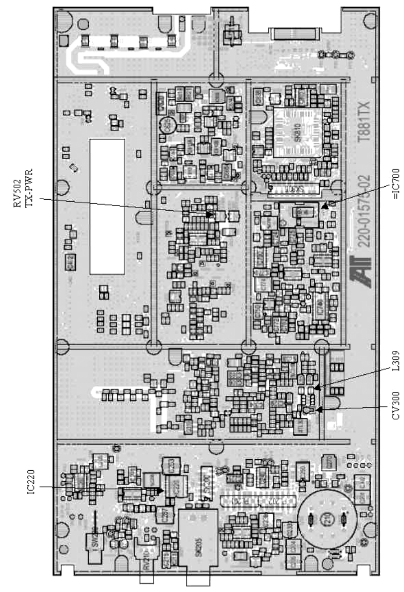
120 20191-100a Paragon-III User Manual
38
Figure 24 - T881-0200 Transmitter Tuning Controls location

120 20191-100a Paragon-III User Manual
39
7. Specifications
GENERAL
Frequency 762 -764 MHz Tx/ 792-794 MHz Rx and 767- 773MHz Tx/797-803MHz Rx
RF/Modem Assembly Size 19.0” W x 17.5.0” H x 12.5” D + 2.0” connector allowance
Frequency Stability 1.0 ppm (-20 to +60ºC)
Supply Voltage
13.8 VDC nominal (negative ground), 10.8 - 16 VDC
or
120 VAC
Circuit protection (radio backplane)
Main fuse (F1): Blade fuse (Maxi-Fuse) 10A :
Power amp. fuse (F2 & F3): Blade fuses (Maxi-Fuse) 2 x 15A (30A total)
Crowbar diodes for reverse polarity protection
RX Current Consumption @ 13.8 VDC 1.5A max. (Two receivers with speaker monitoring)
TX Current Consumption @ 13.8 VDC 1.7A max –5W Exciter T881, 25A – 50W PA AET
Base Station Power Consumption
@ 120 VAC TBD
Channel spacing 50 kHz
Operating Temperature Range -30°C to +60°C (deleted power supply, catalog number with 0 in second to last digit)
-10°C to +60°C (with standard Dual Power Supply assy., catalog number with 2 in second to last digit)
RECEIVER
Selectivity @ 25 kHz
@ 12.5 kHz
85 dB min, 88 dB (Typical)
79 dB min, 80 dB (Typical)
Sensitivity @ 12 dB SINAD -116 dBm*
Spurious Response Rejection 100 dB (Typical)
Intermodulation Rejection
- EIA (25 kHz)
- EIA 300-096 (12.5 kHz) 80 dB (Typical)
75 dB (Typical)
Hum and Noise
- EIA (25 kHz)
- ETS 300-096 (12.5 kHz) 47 dB*
45 dB*
* Psophometrically weighted (De-emphasis response)
TRANSMITTER –5W
Rated Continuous RF Power 70W nominal
Range of Adjustment 35W – 70 W (user adjustable)
Spurious Emissions: - transmit
- standby
-36 dBm to 1GHz, -30 dBm to 3.2GHz
-57 dBm to 1GHz, -47 dBm to 3.2GHz
VSWR Stability 3:1 mismatch
Transmitter Sideband Noise (ACP)
@ +/-50 kHz
@ +/- 1 MHz
-40 dBc
-100 dBc

120 20191-100a Paragon-III User Manual
40
Operation Full duplex
Protocol Dataradio Proprietary E-DBA with OOB AAVL support
Data rates and
Modulation type
xRC16FSK (128 kb/s)
xRC8FSK (92 kb/s)*
xRC4FSK (64 kb/s)*
* Operating under Class I permissive change, subset of 16-Level FSK
POWER AMPLIFIER – 70W
Frequency Range 762-776 MHz
Operative Voltage 13.8 VDC
Current Draw 18-21 Amperes (typical)
Duty Cycle 100% (Continuous)
Power Input 5W
Power Output 70 Watts CW
RF Power Adjustment -3dB (Nominal)
Spurious & Harmonics -70 dBc
input/output Impedance 50 ohms
Load VSWR Tolerance 20:1 (Max) 30 seconds
input/output connectors Type N female
Operating Temperature Range -30 degrees C. to +60 degrees C.
Storage & Transport -40 degrees C. to +70 degrees C.
Humidity 80% at +40 degree C. (non-condensing)
Altitude 10,000 feet maximum
Size 5.25”W x 10.5”H x 13”D
Weight 18 pounds (Nominal)
FCC CERTIFICATIONS FCC IC (DOC)
762-764MHz and 767-773MHz EOTBDP3-T881 -5W exciter T881
EOTBDP3-AMP – 70W PA option AMP
NA
EMISSION DESIGNATORS
Bit rate Baud rate Modulation 700MHz
128 kb/s 32000 xRC16FSK 30K0F1D
96 kb/s 32000 xRC16FSK 30K0F1D
64 kb/s 32000 xRC16FSK 30K0F1D