CalAmp Wireless Networks BDP4-EXCT403 UHF LOW SDR Exciter for BDP4 digital base station User Manual 120 20195 100 P4 700 May21x
CALAMP WIRELESS NETWORKS INC. UHF LOW SDR Exciter for BDP4 digital base station 120 20195 100 P4 700 May21x
user manual
AERCEPTDATARADIOLANDCELLOMEGASMARTLINK
299JohnsonAvenue,Suite110|Waseca,MN56093|t507.833.8819|f507.833.6748|calamp.com
Dataradio P
Pa
ar
ra
ag
go
on
n4
4
Data Base Station
UHF, 700, and 800 MHz with
Crescend Power Amplifier
User Manual
P/N 001-2019-500
Revision 0
May 2010
Preliminary
001-2019-500 Rev 0 Paragon4 – UHF, 700 & 800MHz User Manual
ii
1.PREFACE..............................................................................................................................................................................V
1.1COPYRIGHTNOTICE.......................................................................................................................................................................V
1.2USERMANUALSTATEMENT............................................................................................................................................................V
2.DEFINITIONS.......................................................................................................................................................................VI
3.PRODUCTOVERVIEW............................................................................................................................................................1
3.1INTENDEDAUDIENCE.....................................................................................................................................................................1
3.2GENERALDESCRIPTION...................................................................................................................................................................1
3.3SERVICEANDSUPPORT...................................................................................................................................................................3
3.4PACKAGING..................................................................................................................................................................................4
4.INSTALLATION.......................................................................................................................................................................5
4.1OVERVIEW...................................................................................................................................................................................5
4.2LOCATION....................................................................................................................................................................................5
4.3REARVIEWS.................................................................................................................................................................................6
4.4ELECTRICALCONFIGURATIONS..........................................................................................................................................................7
4.5ANTENNA..................................................................................................................................................................................12
4.6COMPLETINGTHEPHYSICALINSTALLATION........................................................................................................................................12
4.7CHECKINGOUTNORMALOPERATION..............................................................................................................................................12
5.OPERATINGDESCRIPTION...................................................................................................................................................13
5.1RADIOASSEMBLY........................................................................................................................................................................13
6.OPERATION&CONFIGURATION..........................................................................................................................................18
6.1BROWSER‐BASEDINTERFACE.........................................................................................................................................................18
6.3IPNETWORKCONFIGURATION.......................................................................................................................................................19
6.4WEBSERVERLOGIN.....................................................................................................................................................................21
6.5WEBINTERFACE..........................................................................................................................................................................22
6.6UNITSTATUS..............................................................................................................................................................................23
6.7SETUP(BASIC)............................................................................................................................................................................29
6.8SETUP(ADVANCED).....................................................................................................................................................................34
6.9SECURITY...................................................................................................................................................................................65
6.10STATISTICS.................................................................................................................................................................................67
6.11MAINTENANCE...........................................................................................................................................................................73
6.12OOBDATA(OUTOFBANDGPSDELIVERY)......................................................................................................................................81
6.13REMOTETABLE...........................................................................................................................................................................82
6.14SITEMAPANDHELP....................................................................................................................................................................84
7.TROUBLESHOOTINGANDTESTING......................................................................................................................................85
7.1EQUIPMENTREQUIRED.................................................................................................................................................................85
7.2RECOMMENDEDCHECKS...............................................................................................................................................................85
7.3ADDITIONALTESTDETAILS.............................................................................................................................................................90
7.4WINDOWS/UNIXTOOLS...............................................................................................................................................................92
7.5BSCFIRMWAREUPGRADING.........................................................................................................................................................93
8.SPECIFICATIONS..................................................................................................................................................................95
Preliminary
001-2019-500 Rev 0 Paragon4 – UHF, 700 & 800MHz User Manual
iii
FIGURE 1 - FRONT VIEW "RADIO ASSEMBLY" ............................................................................................................................................. 5
FIGURE 2 - TYPICAL RACKMOUNT INSTALLATION OF RADIO MODEM AND CRESCEND PA .......................................................................... 5
FIGURE 6 - PARAGON4 UNIT REAR VIEW ..................................................................................................................................................... 6
FIGURE 7 - BACKPLANE .............................................................................................................................................................................. 6
FIGURE 5 – SIMPLE AC-TO-DC POWER SUPPLY CONFIGURATIONS: BLOCK DIAGRAM ................................................................................ 7
FIGURE 6 – SIMPLE AC-TO-DC POWER SUPPLY CONFIGURATIONS: VIRTUAL RACK-MOUNT INSTALLATION ............................................... 8
FIGURE 10 - SCREW REMOVAL DETAIL ........................................................................................................................................................ 9
FIGURE 11 - FUSES LOCATION .................................................................................................................................................................... 9
FIGURE 13 - MAXI-FUSE ........................................................................................................................................................................... 11
FIGURE 18 - WEB INTERFACE ................................................................................................................................................................... 18
FIGURE 19 - IP NETWORK SETTINGS IN ROUTER MODE (WITH HOST) ...................................................................................................... 20
FIGURE 20 - IP NETWORK SETTINGS IN ROUTER MODE (WITH ROUTER) .................................................................................................. 20
FIGURE 21 - WEB USER INTERFACE – WELCOME SCREEN ........................................................................................................................ 21
FIGURE 22 - UNIT IDENTIFICATION AND STATUS ...................................................................................................................................... 23
FIGURE 23 - UNIT STATUS - RADIO INFORMATION ................................................................................................................................... 24
FIGURE 24 - UNIT STATUS – DIAGNOSTICS ............................................................................................................................................... 26
FIGURE 19 - BACKPLANE -TB1 CONNECTOR ............................................................................................................................................. 28
FIGURE 20 - TB1 CONNECTOR .................................................................................................................................................................. 28
FIGURE 25 - SETUP (BASIC) – GENERAL SETUP ........................................................................................................................................ 29
FIGURE 26 - SETUP (BASIC) – BASIC IP CONFIGURATION ......................................................................................................................... 30
FIGURE 27 - RF (FREQUENCIES) ............................................................................................................................................................... 31
FIGURE 28 - SETUP (BASIC) – SERIAL PORTS SETUP ................................................................................................................................. 33
FIGURE 29 - ADVANCED IP CONFIGURATION - LAN (IP) ......................................................................................................................... 34
FIGURE 30 - ADVANCED IP CONFIGURATION - RF (IP) ............................................................................................................................. 35
FIGURE 31 - ADVANCED IP CONFIGURATION – ROAMING ........................................................................................................................ 36
FIGURE 32 - ADVANCED IP CONFIGURATION – IP SERVICES SETUP ......................................................................................................... 37
FIGURE 33 - NAT ENABLED ON PARAGON4 ............................................................................................................................................. 39
FIGURE 34 - PARAGON4 - EXAMPLE 1 ....................................................................................................................................................... 39
FIGURE 35 - PARAGON4 - EXAMPLE 2 ....................................................................................................................................................... 40
FIGURE 36 - PARAGON4 - EXAMPLE 3 ....................................................................................................................................................... 40
FIGURE 37 - PARAGON4 - EXAMPLE 4 ....................................................................................................................................................... 41
FIGURE 38 - NAT ENABLED ON GEMINIG3 .............................................................................................................................................. 41
FIGURE 39 - GEMINIG3 - EXAMPLE 1 ........................................................................................................................................................ 42
FIGURE 40 - GEMINIG3 - EXAMPLE 2 ........................................................................................................................................................ 42
FIGURE 41 - SNMP: MANAGER/AGENT MODEL ......................................................................................................................................... 43
FIGURE 42 - BRANCH OF THE 1234.MIB OID TREE .................................................................................................................................... 44
FIGURE 43 - BSC.MIB TREE ....................................................................................................................................................................... 45
FIGURE 44 - ADVANCED IP CONFIGURATION – IP ADDRESSING MODES .................................................................................................... 46
FIGURE 45 - BROADCAST WINDOW DETAIL .............................................................................................................................................. 48
FIGURE 46 - EXAMPLE OF DIRECTED BROADCAST FORWARDING ENABLED .............................................................................................. 49
FIGURE 47 - EXAMPLE OF DIRECTED BROADCAST FORWARDING DISABLED ............................................................................................. 50
FIGURE 48 - EXAMPLE OF DIRECTED BROADCAST FORWARDING ENABLED .............................................................................................. 51
FIGURE 49 - EXAMPLE OF LIMITED BROADCAST FORWARDING DISABLED ................................................................................................ 52
FIGURE 50 - REGISTRATION TO MULTICAST GROUP (FIRST STEP) .............................................................................................................. 53
FIGURE 51 - RECEPTION OF MULTICAST PACKETS (SECOND STEP) ............................................................................................................ 53
FIGURE 52 - TYPICAL E-DBA MULTICAST GROUPS ................................................................................................................................. 54
FIGURE 53 - MULTICAST WINDOW DETAILS (ON THE BASE STATION) ..................................................................................................... 55
FIGURE 54 - TYPICAL E-DBA MULTICAST GROUPS (WITH ADDRESSES) ................................................................................................... 55
FIGURE 55 - SETUP (ADVANCED)-OPTIMIZED IP SETTINGS ...................................................................................................................... 56
FIGURE 56 - IP ROUTING........................................................................................................................................................................... 57
FIGURE 57 - ADVANCED IP CONFIGURATION – TIME SOURCE .................................................................................................................. 58
FIGURE 58 - ADVANCED IP CONFIGURATION – ETHERNET (PHY) ............................................................................................................ 59
FIGURE 59 - ADVANCED IP CONFIGURATION – DIAGNOSTIC SETTINGS .................................................................................................... 60
FIGURE 60 - SAMPLE INTERPOLATION CURVE ........................................................................................................................................... 62
FIGURE 61 - SAMPLE CALIBRATION FILE ................................................................................................................................................... 63
FIGURE 62 - ADVANCED IP CONFIGURATION - USER SETTINGS ................................................................................................................ 64
Preliminary
001-2019-500 Rev 0 Paragon4 – UHF, 700 & 800MHz User Manual
iv
FIGURE 63 - SECURITY – PASSWORD AND ENCRYPTION ........................................................................................................................... 65
FIGURE 64 - SECURITY - ACCESS LIST ...................................................................................................................................................... 66
FIGURE 65 - STATISTICS – INTERFACES ..................................................................................................................................................... 67
FIGURE 66 - LAYERS AND PROTOCOLS APPLICABLE TO DATARADIO IMPLEMENTATION ........................................................................... 68
FIGURE 67 - LAYER, PROTOCOLS, AND INTERFACES APPLICABLE TO DATARADIO IMPLEMENTATION ....................................................... 69
FIGURE 68 - RX AND TX CONVENTION .................................................................................................................................................... 69
FIGURE 69 - DATALINK ETHERNET STATISTICS ........................................................................................................................................ 70
FIGURE 70 - DATALINK RF STATISTICS .................................................................................................................................................... 70
FIGURE 71 - STATISTICS - SYSTEM PERFORMANCE ................................................................................................................................... 71
FIGURE 72 - MAINTENANCE – PING TEST ................................................................................................................................................. 73
FIGURE 73 - MAINTENANCE -CONFIGURATION CONTROL (INITIAL SCREEN) ............................................................................................ 74
FIGURE 74 - MAINTENANCE – PACKAGE CONTROL .................................................................................................................................. 75
FIGURE 75 - CONTROL - RF TESTS ............................................................................................................................................................ 76
FIGURE 76- MAINTENANCE – AVAILABLE FEATURE OPTIONS .................................................................................................................. 78
FIGURE 77 - MAINTENANCE – RSSI DISPLAY ........................................................................................................................................... 78
FIGURE 78 - MAINTENANCE –SYSTEM LOG .............................................................................................................................................. 79
FIGURE 79 - A SYSTEM LOG ENTRY .......................................................................................................................................................... 79
FIGURE 80 - AN ASSERT TYPE SYSTEM LOG ENTRY ................................................................................................................................... 80
FIGURE 81 - OUT-OF-BAND ...................................................................................................................................................................... 81
FIGURE 82 - REMOTE TABLE ..................................................................................................................................................................... 82
FIGURE 83 - HELP ICON ............................................................................................................................................................................ 84
FIGURE 84 - PF SWITCH ROCKER DETAIL (ONE SIDE PRESSED) ................................................................................................................. 90
FIGURE 85 - SAMPLE FTP PROGRAM ......................................................................................................................................................... 94
TABLE 1 - ON-AIR DATA SPEEDS AND MODULATION ................................................................................................................................... 2
TABLE 2 - TEST POINTS .............................................................................................................................................................................. 7
TABLE 4 - POWER AMPLIFIER INDICATORS ............................................................................................................................................... 15
TABLE 3 - ICT N+1LED MODULE STATUS DISPLAY ................................................................................................................................ 16
TABLE 5 - SAMPLE INTERPOLATION ENDPOINTS ....................................................................................................................................... 62
TABLE 6 - PLICC SYNTAX ....................................................................................................................................................................... 63
TABLE 7 - POSSIBLE ERROR MESSAGES..................................................................................................................................................... 63
TABLE 8 - CHECKLIST A (AFTER INSTALLATION) ..................................................................................................................................... 86
TABLE 9 - CHECKLIST B (GENERAL) ......................................................................................................................................................... 87
TABLE 10 - CARRIER DEVIATIONS ............................................................................................................................................................ 90
TABLE 11 - TEST TONES GENERATION ..................................................................................................................................................... 91
Preliminary

001-2019-500 Rev 0 Paragon4 – UHF, 700 & 800MHz User Manual
v
1. PREFACE
1.1 Copyright Notice
©2010 CalAmp Corp. All Rights Reserved.
This manual covers the operation of the CalAmp/ Dataradio Paragon4 data base station. Specifications described are typ-
ical only and are subject to normal manufacturing and service tolerances.
CalAmp reserves the right to modify the equipment, its specifications or this manual without prior notice, in the interest of
improving performance, reliability, or servicing. At the time of publication all data is correct for the operation of the
equipment at the voltage and/or temperature referred to. Performance data indicates typical values related to the particular
product.
No part of this documentation or information supplied may be divulged to any third party without the express written con-
sent of CalAmp Corp.
Products offered may contain software which is proprietary to CalAmp Corp. The offer or supply of these products and
services does not include or infer any transfer of ownership.
1.2 User Manual Statement
Every effort is taken to provide accurate, timely product information in this user manual.
Product updates may result in differences between the information provided herein and the product shipped. The informa-
tion in this document is subject to change without notice.
www.CalAmp.com
For additional information, please visit http://www.calamp.com
Preliminary
001-2019-500 Rev 0 Paragon4 – UHF, 700 & 800MHz User Manual
vi
2. Definitions
Access Point Communication hub for users to connect to a wired LAN. APs are important for providing heigh-
tened wireless security.
ADB Agile Dual-Band - GeminiG3 radiomodem model that allows 700/800MHz automatic band
switching capability during roaming.
AES Advanced Encryption Standard (AES) - uses 128-bit encryption to secure data.
Airlink Physical radio frequency connections used for communications between units.
ARP Address Resolution Protocol – Maps Internet address to physical address.
AAVL Autonomous Automatic Vehicle Location. Optional feature that involves using GPS (Global Po-
sitioning System) signals from the mobile unit by the Host PC.
Backbone The part of a network that connects most of the systems and networks together, and handles the
most data.
Bandwidth The transmission capacity of a given device or network.
Base Designates products used as base stations in VIS systems. They currently include the Paragon
family of products up to the Paragon4 radiomodems.
Browser An application program that provides a way to look at and interact with all the information on the
World Wide Web.
BSC Base Station Controller - An async controller-modem designed for the radio base station in mo-
bile systems. A component of Paragon4 radiomodem base stations.
COM Port RS-232 serial communications ports of the Paragon4 wireless radiomodem.
Cycle Mark Signal transmitted on an E-DBA network that keeps the network synchronized.
Default Gateway A device that forwards Internet traffic from your local area network.
DHCP Dynamic Host Configuration Protocol - A networking protocol that allows administrators to as-
sign temporary IP addresses to network computers by "leasing" an IP address to a user for a li-
mited amount of time, instead of assigning permanent IP addresses.
DNS Domain Name Server - The on-line distributed database system used to map human-readable ma-
chine names into IP addresses.
Domain A specific name for a network of computers.
Dynamic IP Addr A temporary IP address assigned by a DHCP server.
E-DBA Enhanced Dynamic Bandwidth Allocation – Dataradio proprietary protocol that schedules all in-
bound and outbound Airlink traffic to minimize contention.
Ethernet Ethernet is a frame-based computer networking technology for local area networks (LANs). It de-
fines wiring and signaling for the physical layer, and frame formats and protocols for the media
access control (MAC)/data link layer of the OSI model. Ethernet is mostly standardized as IEEEs
802.3.
Feature Key Method used to implement customer’s option(s) selected at the time of radiomodem purchase
(factory-installation) or as add-on (field-installation).
Firewall A set of related programs located at a network gateway server that protects the resources of a
network from users from other networks.
Firmware The programming code that runs a networking device.
Fragmentation Breaking a packet into smaller units when transmitting over a network medium that cannot sup-
port the original size of the packet.
FTP File Transfer Protocol - A protocol used to transfer files over a TCP/IP network.
Preliminary
001-2019-500 Rev 0 Paragon4 – UHF, 700 & 800MHz User Manual
vii
Gateway A device that interconnects two or more networks with different, incompatible communications
protocols and translates among them.
GeminiG3 Third generation of GeminiPD VIS products. High specs dual DSP mobile radiomodem with Data-
radio Parallel Decode™ technology
HDX Half Duplex. Data transmission that can occur in two directions over a single line, using separate
Tx and Rx frequencies, but only one direction at a time.
HTTP HyperText Transport Protocol - The communications protocol used to connect to servers on the
World Wide Web.
IPCONFIG A Windows 2000 and XP utility that displays the IP address for a particular networking device.
MAC ADDRESS Media Access Control - The unique address that a manufacturer assigns to each networking de-
vice.
MIB Management Information Base (MIB)-a logical, hierarchically organized database of network
management information. Used in SNMP.
NAT Network Address Translation - NAT technology translates IP addresses of a local area network to
a different IP address for the Internet.
Network A series of computers or devices connected for the purpose of data sharing, storage, and/or
transmission between users.
Network speed This is the bit rate on the RF link between units.
Node A network junction or connection point, typically a computer or work station.
OID An object identifier or OID is an identifier used to name an object and is the numerical equivalent
of a path. In SNMP, an OID consists of numbers separated by decimal points. Structurally, an
OID consists of a node in a hierarchically assigned namespace.
OIP Optimized IP – Compresses TCP and UDP headers, and filters unnecessary acknowledgments.
This makes the most use of the available bandwidth.
OTA Over-The-Air - Standard for the transmission and reception of application-related information in
a wireless communications system
Palette Synchronization patterns used to identify the speed and coding of packets transmitted over-the-air
in E-DBA.
Paragon4 IP-based data radio base station used in mobile networks and designed specifically to fit the needs
of vehicular applications. Runs up to 128 kb/s
Parallel Decode Technology featuring dual receivers for added data decode sensitivity in multi-path and fading
environments. (United States Patent No: 6,853,694 B1)
PHY A PHY chip (called PHYceiver) provides interface to the Ethernet transmission medium. Its pur-
pose is digital access of the modulated link (usually used together with an MII-chip).
The PHY defines data rates and transmission method parameters.
PDU Protocol Data Unit - A PDU is a message of a given protocol comprising payload and protocol-
specific control information, typically contained in a header. PDUs pass over the protocol inter-
faces that exist between the layers of protocols.
Ping Packet INternet Groper - An Internet utility used to determine whether a particular IP address is
online.
PLC Programmable Logic Controller. An user-provided intelligent device that can make decisions,
gather and report information, and control other devices.
Roaming Movement of a wireless node (GeminiG3 radiomodems) amongst Multiple Access Points (Para-
gon4). Paragon4 radiomodems support seamless roaming.
Router A networking device that connects multiple networks together.
Preliminary
001-2019-500 Rev 0 Paragon4 – UHF, 700 & 800MHz User Manual
viii
RS-232 Industry–standard interface for data transfer.
Smart Combining Digital processing method used to combine “Spatial Diversity” signals to optimize performance.
(See Parallel Decode)
SNMP Simple Network Management Protocol - Provides a means to monitor and control network devic-
es, and to manage configurations, statistics collection, performance, and security.
Spatial Diversity Composite information from independent diversity branches using antennas spaced apart is used
with “Smart Combining” to minimize fading and other undesirable effects of multipath propaga-
tion. (See Parallel Decode)
SRRCnFSK Square Root Raised Cosine (n = level) Frequency Shift Keying. Type of frequency modulation of
data signals performed by the Paragon4 radiomodem.
Static IP Address A fixed address assigned to a computer or device that is connected to a network.
Static Routing Forwarding data in a network via a fixed path.
Subnet Mask A bit mask used to select the bits from an IP address that correspond to the subnet. Each mask is
32 bits long, with one bits in the portion that identifies a network and zero bits in the portion that
identifies a host.
Switch (Ethernet) Computer-networking device that allows sharing a limited number of ports to connect computing
devices to host computers. Replaces network hubs (layer1),
switches (layer2), routers (layer3).
Sync Data transmitted on a wireless network that keeps the network synchronized.
TCP/IP Transmission Control Protocol/Internet Protocol - A transport (layer4) protocol for transmitting
data that requires acknowledgement from the recipient of data sent. Handles retries and flow con-
trol.
Telnet Network (layer5) protocol used on the Internet or on LAN connections.
TFTP Trivial File Transfer Protocol - A version of the TCP/IP FTP protocol that has no directory or
password capability.
Topology The physical layout of a network.
Transparent A transparent unit transmits all data without regard to special characters, etc.
UDP User Datagram Protocol - A transport (layer4) protocol for transmitting data that does not require
acknowledgement from the recipient of the data that is sent.
Upgrade To replace existing software or firmware with a newer version.
URL Universal Resource Locator - The address of a file located on the Internet.
VIS Vehicular Information Solutions. Dataradio’s name for a series of products specially designed for
mobile data.
WLAN Wireless Local Area Network - A group of computers and associated devices that communicate
with each other wirelessly.
Preliminary
001-2019-500 Rev 0 Paragon4 – UHF, 700 & 800MHz User Manual
1
3. PRODUCT OVERVIEW
This document provides information required for the setting up, operation, testing and trouble-shooting of
the Dataradio® Paragon4™ radio-modem base station.
3.1 Intended Audience
This document is intended for engineering, installation, and maintenance personnel.
3.2 General Description
The Paragon4 radio base station is a factory-integrated industrial-grade IP-based data product used in mobile
networks and is designed specifically to fit the needs of vehicular applications. It features dual receivers for
added data decode sensitivity in multi-path and fading environments.
When used with Dataradio’s state-of-the-art GeminiG3 mobile IP data solution, the system delivers
unequaled high-speed data performance and unmatched effective throughput.
All Paragon4 models are supplied in a standard 19-inch wide rackmount. The Paragon4 full-duplex radio-
modem chassis assembly includes:
• A second generation high-speed Dataradio “Base Station Controller” module (BSC2) that uses an open
architecture that simplifies the implementation process. The BSC2 module comes equipped with a built-
in IP router with dual Ethernet 10/100 BaseT interfaces.
• Option for internally/externally generated high-stability (+/-0.1ppm) 10MHz reference source, factory
installed.
• Dual, independently synthesized Receiver radio module.
• High-performance synthesized 0.2W Exciter radio module.
For all Paragon4 radio modem units:
• One Power Amplifier (PA) module is required for the regular usage.
• Duplexer and backup power units are custom furnished items.
• Wire line modem(s) are optional items.
• Laptop PC and its application software are user-supplied items.
• Optional Router – Adding a second router anywhere within a network is required to make it fault
tolerant.
Preliminary

001-2019-500 Rev 0 Paragon4 – UHF, 700 & 800MHz User Manual
2
3.2.1 Features
• Parallel Decode™ technology featuring dual receivers for added decode sensitivity in multi-path
and fading environments.
• Fully IP-based product models, using an Optimized IP layer that reduces IP overhead for the RF
link
• Sophisticated dual DSP-based modem design provides added system performance, fewer retries
and more effective throughput.
• Full duplex mode of operation
• Base Station with an RF Power Amplifier. The Power Amplifier is considered a stand-alone
module.
• On-air data speeds and modulation types supported (dependent on “Feature Key” selected1):
Table 1 - On-air data speeds and modulation
Channel Type
UHF 700 MHz 800 MHZ
Modulation
type 25 kHz 12.5 kHz 50 kHz 25 kHz 12.5 kHz 25 kHz NPSPAC
SRC16FSK 64 kb/s 32 kb/s 128 kb/s 64 kb/s 32kb/s 64 kb/s 32kb/s
SRC8FSK 48 kb/s 24 kb/s 96kb/s 48kb/s 24kb/s 48 kb/s 24kb/s
43.2 kb/s 43.2kb/s 43.2 kb/s
SRC4FSK 32 kb/s 16 kb/s 64kb/s 32 kb/s 16kb/s 32 kb/s 16kb/s
• Uses Dataradio’s Next generation high-efficiency Enhanced-DBA (E-DBA) over-the-air protocol
• Over-the-air compatible with GeminiG3 mobile products
• Out-of-band signaling enables transmission of GPS reports with no effect on system performance.
• Flash programmable firmware
3.2.2 Configuration
Paragon4 units are factory-configured based on each customer’s individual system requirements. Net-
work-specific installation and/or operating instructions should be prepared in conjunction with Dataradio
System Engineering department, which also handles field deployment.
Instructions and examples given in this manual are based on Paragon4 operating software version current
at the time of writing this document and may not apply to earlier or later software versions. Screen cap-
tures used throughout this document may vary from actual screens. Configuration changes or upgrades
are web-based.
1 Method used to implement customer’s option(s) selected at the time of radiomodem purchase (factory-installation) or as add-on
(field-installation).
Preliminary

001-2019-500 Rev 0 Paragon4 – UHF, 700 & 800MHz User Manual
3
3.3 Service and Support
3.3.1 Product, Warranty, RMA and Contact Information
CalAmp Corp guarantees that every DataradioParagon4 base station will be free from physical defects in
material and workmanship for one (1) year from the date of purchase when used within the limits set forth
in the Specifications section of this manual. Extended warranty plans are available.
If the product proves defective during the warranty period, contact CalAmp Customer Service to obtain a
Return Material Authorization (RMA).
3.3.1.1 RMA Request
Contact Customer Service:
CalAmp – Dataradio
299 Johnson Avenue, Suite 110
Waseca, MN 59093-USA
phone: (1) 507.833.8819
fax: (1) 507.833.6748
BE SURE TO HAVE THE EQUIPMENT MODEL AND SERIAL NUMBER, AND BILLING AND
SHIPPING ADDRESSES ON HAND WHEN CALLING.
When returning a product, mark the RMA clearly on the outside of the package. Include a complete de-
scription of the problem and the name and telephone number of a contact person. RETURN REQUESTS
WILL NOT BE PROCESSED WITHOUT THIS INFORMATION.
For units in warranty, customers are responsible for shipping charges to CalAmp Corp. For units returned
out of warranty, customers are responsible for all shipping charges. Return shipping instructions are the
responsibility of the customer.
3.3.2 Product Documentation
CalAmp Corp reserves the right to update its products, software, or documentation without obligation to
notify any individual or entity. Product updates may result in differences between the information pro-
vided in this manual and the product shipped. For the most current product documentation, visit
www.calamp.com for spec sheets.
3.3.3 Technical Support
Technical support hours: Monday to Friday 9:00 AM to 5:00 PM, Eastern Time
CalAmp – Dataradio Corp
6160 Peachtree Dunwoody RD., suite C-200
Atlanta, Georgia 3032
phone: (1) 770.392.0002
fax: (1) 770.392.9199
Email address: PSMGsupport@calamp.com
Preliminary
001-2019-500 Rev 0 Paragon4 – UHF, 700 & 800MHz User Manual
4
3.4 Packaging
Each Paragon4 radio-modem base station – UHF, 700, or 800MHz – normally leaves the factory pack-
aged as follows:
• A Dataradio base station “Radio-modem assembly”.
• A Crescend 70W (for 700 and 800 MHz) or 100W (for UHF) rack-mount power amplifier mod-
ule.
• An ICT 13.8VDC 34A AC/DC rack-mount power supply, if ordered that way.
• One six-foot 120VAC power cord (NEMA 5-15p plug to IEC 60320-C19 receptacle) for the
AC/DC power supply.
• Two DC power cables to connect the radio-modem assembly and the power amplifier module to
the DC power supply.
• Coax cable (24 inch) to connect the Exciter module to the power amplifier.
Frequently, Paragon4 product components are field-assembled prior to customer delivery.
The cabinetry may then be supplied in one of several custom rack-mount configurations that may also in-
clude fan, backhaul modems, duplexer/filters/combiners, and ancillary equipment.
If damage has occurred to the equipment during shipment, file a claim with the carrier immediately.
Preliminary
001-2019-500 Rev 0 Paragon4 – UHF, 700 & 800MHz User Manual
5
4. Installation
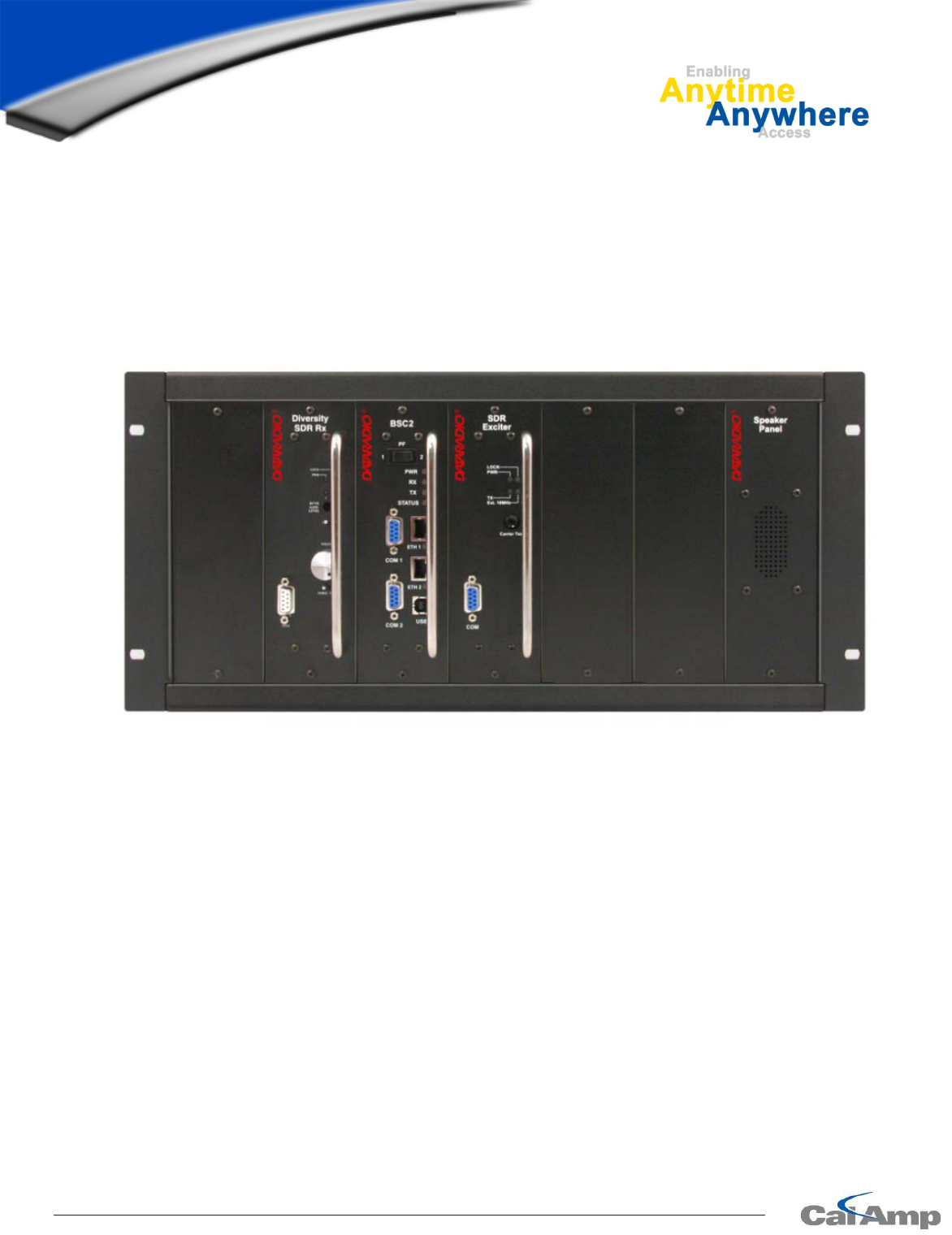
Figure 1 - Front view "Radio Assembly"
4.1 Overview
The cabinet and rack-mount housing the Paragon4’s radio-modem and Power Amplifier is generally
installed in a sheltered facility. Occasionally located adjacent to the nerve center of the user’s
network, it is often located near tower sites or at remote locations where it operates unattended.
Furnishings needed include power, cabling, and installation of antenna, landline or microwave mod-
em, and host PC or portable computer. Details of these are outside the scope of this manual. This ma-
nual covers the radio-modem assembly. The power amplifier has its own user manual that is incorpo-
rated by reference at the moment of the order.
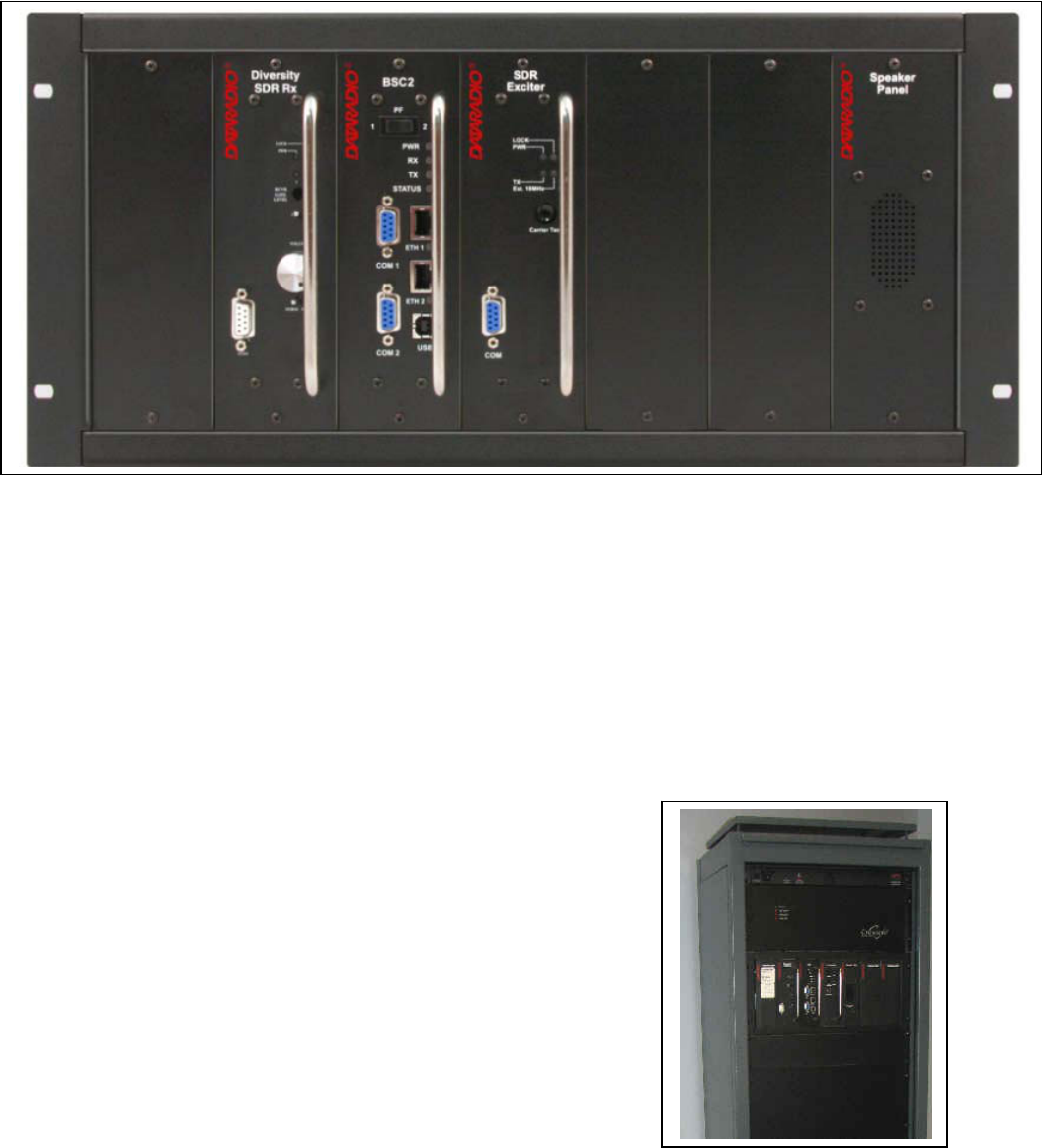
4.2 Location
Be sure to place the Paragon4 unit in such a way that:
• The LEDs can be seen (as an aid in troubleshooting)
• Access to the antenna connector and to the back connectors
is possible without removing the unit
• Sufficient air may flow around the unit to provide adequate
cooling.
Figure 2 - Typical rackmount installation of radio modem and Crescend PA
Preliminary
001-2019-500 Rev 0 Paragon4 – UHF, 700 & 800MHz User Manual
6
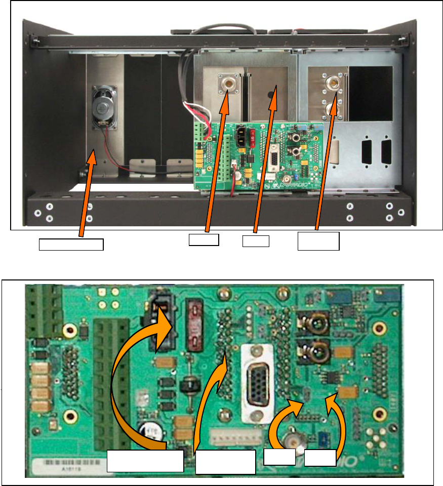
4.3 Rear Views
Figure 3 - Paragon4 unit rear view
Figure 4 - Backplane
RX1
RX2
BSC2
Exciter
Speaker Panel
.
10-amp fuse J18
Access
port J9
J19
Preliminary
001-2019-500 Rev 0 Paragon4 – UHF, 700 & 800MHz User Manual
7
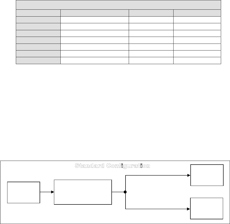
Table 2 - Test Points
Backplane Test Points Rx/Tx
Test J9 Access port Alternate Pinout
Ground GND Pin 14 J18, J19 – Pin 3
SINAD & Distortion RX1 -Differential 1P-Pin3; 1N-Pin8 J18- Pins 1,2
SINAD & Distortion RX2-Differential 2P-Pin4; 2N-Pin9 J19 – Pins 1,2
RSSI RSSI 1 -Differential 1P-Pin1; 1N-Pin6 J18 – Pins 4,5
RSSI RSSI 2-Differential 2P-Pin2; 2N-Pin7 J19 – Pins 4,5
TX Audio TXAP-Differential (+ve side only) 1P-Pin 5
Key Transmitter /TXKEY-single ended Pin 15
4.4 Electrical Configurations
Standard 120 VAC electrical power is required. It should be capable of providing at least 10A to
power Paragon3 unit (<6A) and ancillary equipment.
4.4.1 Standard Power Supply Configurations
The standard configuration for supplying the required +13.8 VDC to the Paragon4 base station and the
Crescend Power Amplifier is shown in the two figures below, a simple block diagram and a virtual rack-
mount installation. The base station and the power amplifier module receive 13.8 VDC power inputs
from the ICT22012-70N power supply module powered at 120 VAC.
Figure 5 – Simple AC-to-DC power supply configurations: Block Diagram
120 VAC
AC/DC Power Supply
ICT22012-70N
(34 Amp DC Continuous)
PA
Crescend
Paragon4
Base Station
Preliminary
001-2019-500 Rev 0 Paragon4 – UHF, 700 & 800MHz User Manual
8
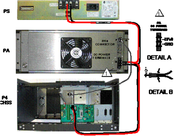
Figure 6 – Simple AC-to-DC power supply configurations: Virtual rack-mount installation
Normally used at room ambient temperatures, the ICT22012-70N can operate within its specifications
over a range of -30 to +52 °C. Although it is a high efficiency switched mode power supply, a considera-
ble amount of heat is generated during normal operation. While in use, ensure that an adequate flow of
cooling air is able to circulate around the power supply, and that the air intake vents on the sides of the
unit are not inadvertently covered.
Caution:
Do not operate this unit in a completely enclosed cabinet.
4.4.2 ICT22012-70N DC Power Supply
The rack-mounted ICT 22012-70N power system components used consist of a backplane and two (-70
model) modules. Each provides 450 watts of continuous DC power. The system is designed with active
sharing technology to distribute the load current among the modules. Each module is equipped with a
high power Schottky OR-ing diode for true redundancy. If a module failure occurs, the other module(s)
will continue to supply power.
Each unit is protected in several ways:
• Fuse against over current on the AC input.
• Current Limit and Foldback – Prevents the load from drawing current above the maximum al-
lowed value.
• Sudden energy surges on each module – Thermistor against inrush current.
Preliminary
001-2019-500 Rev 0 Paragon4 – UHF, 700 & 800MHz User Manual
9
Prior to powering up, ensure that both voltage selection switches (located on the back) are set to the
proper voltage for your operation. Available settings are 120 or 220 volts. The ICT 22012-70N metal
enclosure is internally connected to earth ground via its individual, rear-connected, 120VAC (NEMA 5-
15p plug to IEC 60320-C19 receptacle) power cord. Therefore, the system must be operated from an out-
let with a proper grounding connection.
Cautions:
It is important that the side ventilation holes are unobstructed at all times. Do not oper-
ate this unit in a completely enclosed cabinet.
High current leakage, use only the cord supplied with this equipment for power.
If accessing modules, power at both the switch and the AC inlet must be disconnected to
ensure operator safety.
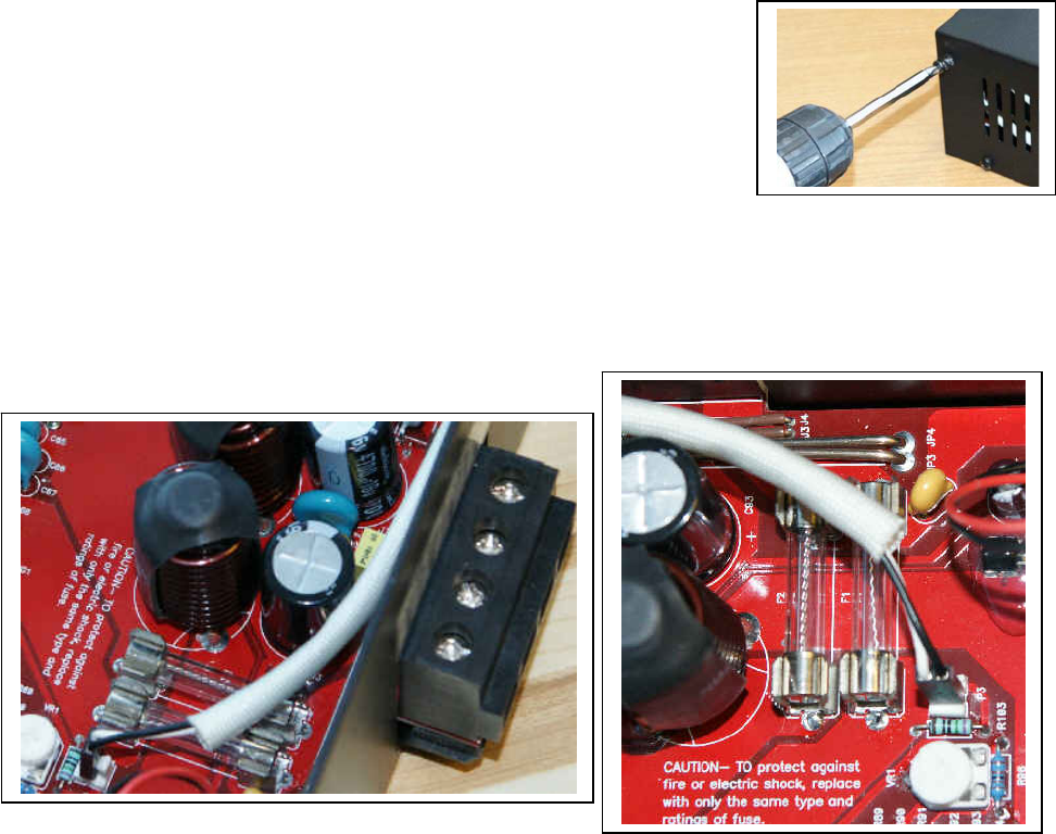
4.4.2.1 Fuse Replacement
To access the fuses, the ICT unit cover must be removed. Ensure that power (cable, battery or solar
source) is removed. Remove eight side screws and washers (Figure 7).
Slide the cover off. Referring to the illustrations in Figure 8, locate the two
32V 35A fuses and replace as needed. Once completed, reverse the above
steps to re-install cover. Only finger tighten the eight screws.
Figure 7 - Screw removal detail
Caution:
To protect against fire or electrical shock, replace with only the same type and
ratings of fuse.
Figure 8 - Fuses Location
Preliminary

001-2019-500 Rev 0 Paragon4 – UHF, 700 & 800MHz User Manual
10
4.4.2.2 Power Supply Connections and Torque Settings
Warning:
Securing the DC Power Supply cable into the DC connector to provide a good electrical connec-
tion is essential. Over time, the wires tend to compress in the DC connector resulting in an in-
creasingly poorer connection. Consequently, as high current is drawn, the connector heats up
increasing the resistance thereby causing still more heat until the connector eventually burns up.
Although screws securing DC cables to the Power Supply terminals are tightened to the torque set-
tings given below prior to new system delivery, they must be re-tightened as part of the commission-
ing process and re-tightening is also part of the regular maintenance schedule.
Prior to replacing a Power Supply module into an existing system, inspect the cable and re-terminate
the wires if the strands have previously been twisted together or show any sign of damage.
Cut the wire at the end of the insulation and then strip approximately 11mm (.43 inch) of insulation
off the cable. DO NOT TWIST THE WIRE STRANDS. Insert the cable into the screw terminal and
tighten the screw to secure the cable as per the torque settings given below.
Torque Settings:
The manufacturer recommends torque setting all power supply terminal screws to a minimum of:
• For the ICT 22012-70N Power Supply; 35 in-lb
Note: CalAmp-Dataradio uses a Sturtevant Richmont 29-piece adjustable torque screwdriver
model CAL36/4K.
After tightening, pull on the cable to check the cable is secured tightly into the screw terminal.
4.4.3 Crescend Power Amplifier
The Crescend power amplifier receives its +13.8VDC power from the ICT DC power supply through a
10AWG DC power cable. In the standard configuration shown in Figure 3, there is no in-line fuse be-
tween the power supply and power amplifier, all the short-cct and foldback protection is done by the ICT
power supply. In this configuration, the voltage drop through the power cable is minimize. Nonetheless, if
required a DC power cable with an in-line fuse can be ordered from the factory.
The power amplifier is maintenance free, only LED indications are present on the front panel. The loca-
tion of the DC power terminal block, the “RF In” as well as the “RF Out” N-type female connectors are
all on the back side of the power amplifier module.
For the 700 and 800MHz models, the power output is normally set to 70W and for the UHF model, it is
set to 100W (or lower depending on the work order) at time of manufacture or via RMA. However, to
allow for field adjustment of the output power to meet the ERP granted by the transmission site license, a
potentiometer is accessible via a small round opening on the underside of the power amplifier. Adjust us-
ing a small tuning screwdriver. CalAmp does not recommend adjusting below 35 watts for the 700 and
800MHz models and 50W for the UHF model.
As per Industry Canada Radio Standard Specification #131, paragraph 5.3:
“For the 700 and 800MHz models, the amplifier module delivers 70W with 28dB gain at 100mW
input over a large nominal bandwidth (500-1000MHz) designed platform. For the UHF model,
the amplifier module delivers 100W with 30dB gain at 100mW input over a large nominal band-
width (200-800MHz) designed platform The manufacturer's rated output power and power toler-
ance of this equipment is for single carrier operation in the specified frequency range. It should
not be used for multiple carrier operations or outside its specified range.”
Preliminary
001-2019-500 Rev 0 Paragon4 – UHF, 700 & 800MHz User Manual
11
Although a rear-mounted fan brings in air from the back and blows it across the heatsink fins, a consider-
able amount of heat is generated during normal operation. The amplifier must have a minimum of 3 inch-
es of open space behind the rear fan to allow adequate ventilation. The air inlets and outlets should be
checked every 30 days and cleaned if necessary. If dust and dirt are allowed to accumulate, the cooling
efficiency will be diminished. Using either compressed air or a brush with soft bristles, loosen and re-
move accumulated dust and dirt from the air inlet panels.
Caution:
Do not operate this unit in a completely enclosed cabinet.
Crescend Terminal Block Torque Settings:
Although the manufacturer does not specify definite torque settings for its terminal block screws, the fol-
lowing values can be used:
• 8 In-lb (9 maximum).
4.4.4 Paragon4 Power and Ground Connections
4.4.4.1 Power Connections
The Paragon4 base station’s modem-controller, radio (dual-RX & TX) and speaker panel modules receive
their +13.8VDC power via the backplane PCB. A 12AWG DC power cable provides power to the back-
plane PCB at the heavy duty power connector J20.
4.4.4.2 Ground Connections
The Paragon4 base station chassis requires a secure ground connection. A grounding 8-32 threaded
throughole pemstud fitted with a 8-32 screw, lockwasher and nut is provided on the bottom- rear of the
chassis, behind the speaker panel.
• Install a 3-4ft 10AWG grounding wire, crimped on both sides with terminal rings. Place one side over
the 8-32 screw on the non-exposed chassis side and firmly tighten with the lockwasher and nut.
• Place the other side on the rear side the power supply metal case, near the 25-pin connector. Use a ½
in 4-40 screw with lockwasher to secure the terminal ring to the metal case.
• If a –DC rail (0V) is installed as part of the system, the grounding lead may alternatively be fitted to
the rail terminal.
Caution:
Improper grounding between power supply case and rack frame may result in harmful voltage poten-
tials and/or miscellaneous power supply switching noise problems in both receivers and transmitter.
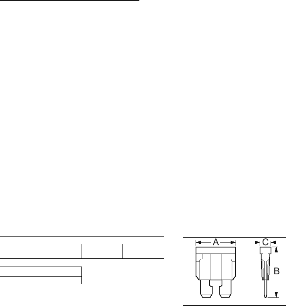
4.4.5 Backplane Fuses
Blade fuses (Maxi-Fuse) are used on the Radio assembly backplane:
Fuse Type Dimensions – Inch (mm)
A B C
Maxi-Fuse 1.15 (29.21) 1.35 (34.29) .35 (8.89)
Fuse # F1
Values 10A
Figure 9 - Maxi-Fuse
Preliminary
001-2019-500 Rev 0 Paragon4 – UHF, 700 & 800MHz User Manual
12
4.5 Antenna
4.5.1 Overview
The Paragon4 unit commonly uses three antennas (one transmit and two receive) unless a duplexer is
used with one of the receive antennas; then only two antennas would be needed. If the 10MHz Dis-
ciplined Clock option is sought, there is another GPS antenna in addition to the three already men-
tioned. They should be mounted according to any guidelines supplied with the antennas. For antennas
placement and spacing, consult System Engineering.
4.5.2 Cabling and Connection
1- Route good quality 50-ohm double-shielded coaxial cable(s) (e.g. RG-214 or Heliax) from the se-
lected antenna position(s) to the Paragon4 Radio assembly.
2- Referring to Figure 3 for locating modules, terminate the RX-1 and RX-2 cable-ends at their re-
spective module rear position with N-type connectors.
3- Similarly, terminate the TX cable-end at the rear position of the Power Amp’s module with an
N-type connector.
Caution:
When terminating RF cables use brand-name crimping tools (such as AMP, Jensen,
Crimp-Master, etc…) of the correct size for the cable and type of connector used.
Common pliers are NOT acceptable.
4.6 Completing the physical Installation
Paragon4 products are factory-configured to user’s requirements and are shipped ready to run.
After new installations:
• Re-check that all connections are secure on the radio-modem assemblies (antennas, PC, power
cords etc.)
• Check that fuses are inserted.
• Turn power supply ON.
You are now ready to check for normal operation (as per paragraph 4.7) and to run the Dataradio web
interface (described in section 6) for testing or trouble-shooting.
4.7 Checking out Normal Operation
1- Check that power is applied.
2- Check Radio assembly lights for proper operation as per section 5.1
3- Check for proper operation of the BSC2 LEDs.
4- Using the web interface program and an in-line wattmeter, check forward & reverse power to
confirm main antenna installation.
5- Using the web interface, check the RF Data Link with a mobile that can be heard.
If user application and mobiles are available, test the installation by going through a normal sequence
of transmitting and receiving messages.
Preliminary
001-2019-500 Rev 0 Paragon4 – UHF, 700 & 800MHz User Manual
13
LOCK
PWR
RCVR
GATE
LEVEL
VOLUME
NORM -
Diversit
y
SDR Rx
5. Operating Description
5.1 Radio Assembly
The Radio assembly component of each Paragon4 product – UHF, 700 or 800 MHz – is made up of a
high performance synthesized radio base station designed for single channel operation. The Radio
Assembly’s modules are commonly installed in a standard, 19-inch wide rack frame.
The complement of modules is:
• 1 x Receiver module
• 1 x Exciter module
• 1 x BSC2 (controller-modem)
• 1 x 70 or 100-Watt Power Amplifier 19” rack-mount assembly
• 1 x Power Supplies
• 1 x Speaker panel
For locating each module, refer to Figure 3 above.
5.1.1 Receiver module
The receiver has several front panel controls and indicators. These are:
• Four LEDs:
PWR LED
Green normal operation
Amber bootloader program running
Red malfunction / reset
LOCK
LED
Green PLL locked
Red PLL not locked
1 LED
Green RF carrier signal on audio channel 1 is above ma-
nually adjusted mute threshold
Off RF carrier signal on audio channel 1 is below ma-
nually adjusted mute threshold
2 LED
Green RF carrier signal on audio channel 2 is above ma-
nually adjusted mute threshold
Off RF carrier signal on audio channel 2 is below ma-
nually adjusted mute threshold
• RCVR GATE LEVEL - Mute threshold adjustment. It sets the RF signal
level required to open the mute gate and allow audio to pass to the speak-
er.
• 1 / 2 Switch – Manual selection of Channel 1 or 2 audio
• Volume - The audio output delivers up to 1 watt to the speaker. Always set volume knob to min-
imum when not in use to reduce current consumption.
• NORM-MON Switch – Manual selection between MONitor: audio unmuted (continuous audio
monitoring) and NORMal: audio unmuted only when above the manually adjusted mute threshold
level
• one DE-9 RS-232 ports for setup
Preliminary

001-2019-500 Rev 0 Paragon4 – UHF, 700 & 800MHz User Manual
14
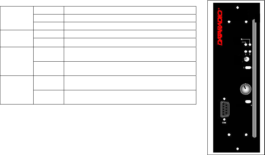
5.1.2 Exciter module
The Exciter’s front panel controls and indicators are:
• LED indicators, according to the table below.
*The cause of Fault or Warning conditions will be displayed on the Unit Status web page
and recorded in the Maintenance
Æ
System Log.
• Carrier test - momentarily keys the transmitter ON while pressed (used for test purposes only). If the
Carrier is pressed for 4 seconds or more the exciter starts the test mode and keeps transmitting until
the next press of the button.
• One DE-9 RS-232 ports for setup.
5.1.3 BSC2 Module
The BSC2's front panel connectors and indicators are:
Green Red Flashing Amber Off
Power Normal Fault * Warning *
TX Idle (un-
keyed)
Normal
Mode:
Transmitting
in normal
mode
Test Mode:
transmitting in
test mode
Idle
10 MHz 10 MHz
Locked
10 MHz con-
nection bro-
ken, unable to
lock
Acquiring 10
MHz Lock
Idle if 10
MHz was
never con-
nected.
Lock Synth lock,
Normal
Synth unlock
Fault
Programming
mode
PWR
LED
Green Normal operation
Red Bootstrap step 1 – lights for <5 sec.
Amber Bootstrap step 2 – lights for <5 sec.
Red
flashing Hardware error, check Unit Status web page
RX LED Green Flashes for each data packets received
Red Discard RX packet (factory-use)
TX LED
Green Flashes for each data packet transmitted
Amber
Flashes for each data packet transmitted
(check for lost Host connection on Unit Stat
web page)
Red
Continuously ON during TXON test (max.
20 sec)
Flashes during CWID key-down
Off When AirLink down selected by PF rocker
switch
STATUS
Green Flashes each time PF1 or PF2 is pressed
Amber
Flashes each second PF1 is kept pressed
Toggles “AirLink down mode” after 4
seconds
LOCK
PWR
TX
Ext. 10MHz
COM
Carrier Test
SDR
Exciter
Preliminary
001-2019-500 Rev 0 Paragon4 – UHF, 700 & 800MHz User Manual
15
• 2x DE-9 RS-232 ports for setup and user data
• 1x rocker switch (positions PF 1 and 2) to select various test modes. See paragraph 5.3.2.
• 2x Ethernet ports – for setup and user data
• 2x Ethernet LEDs (status & activity)
• USB port – reserved.
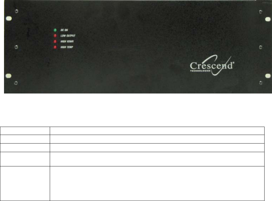
5.1.4 Power Amplifier
Model using Crescend Technologies power amplifier (Illustrations not drawn to scale). The location and
function of the power amplifier's front panel status indicators are shown in Figure xx and described in the
table below:
Table 3 - Power Amplifier indicators
LED Function
DC ON Lights green when DC power (+13.8 VDC) is applied
LOW OUTPUT Lights red when output power drops to approximately 80-85% of set output power
HIGH VSWR Lights red when VSWR exceeds approximately 2.5:1. At which point, the amplifier
output is reduced. The higher the load VSWR, the more the output power is reduced.
HIGH TEMP
Lights red when the amplifier exceeds a safe operating temperature
(Operating temperature range = -30 °C to +60 °C)
When the heatsink reaches an unsafe level, the output power of the amplifier is re-
duced by approximately 50%. This keeps the channel on-air while providing some
short-term protection. Address the underlying cooling issue as soon as possible.
Preliminary
001-2019-500 Rev 0 Paragon4 – UHF, 700 & 800MHz User Manual
16
Speaker
Panel
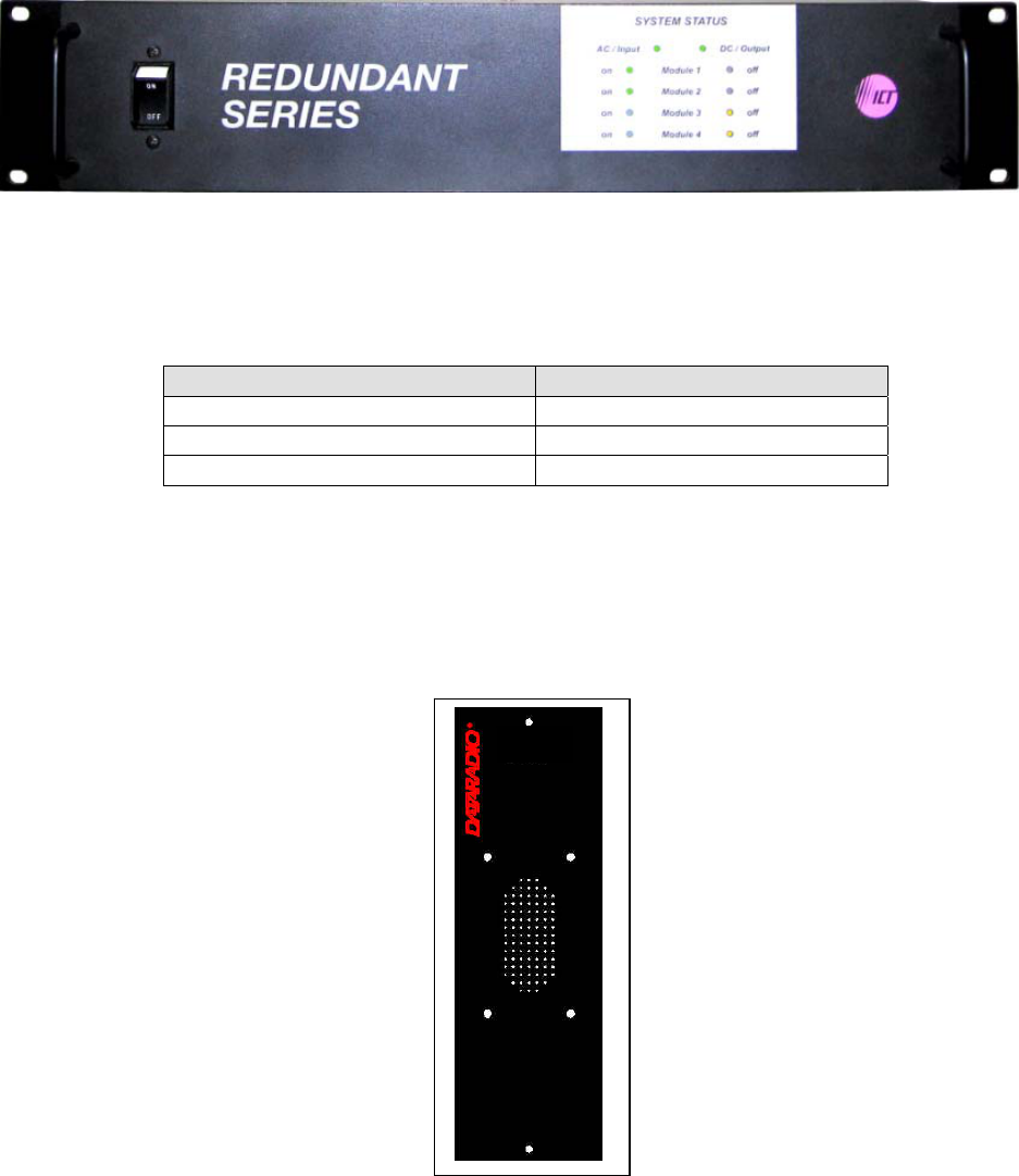
5.1.5 Power Supply
The power supply modules are manufactured by ICT (Innovative Circuit Technology Ltd).
LED indicators are provided as standard feature. They provide module information as shown in Table 4.
Table 4 - ICT N+1LED Module Status Display
GREEN YELLOW
AC line voltage is present Module is not present in the slot
DC output voltage is present Module is not producing any output
Module voltage is present
For more information on these power supply modules please refer to ICT N+1 Redundant Power Supply
Instruction Manual from ICT.
5.1.6 Speaker Module
The speaker panel is fitted with an 8Ω speaker.
Preliminary
001-2019-500 Rev 0 Paragon4 – UHF, 700 & 800MHz User Manual
17
5.1.7 Hardware Options
5.1.7.1 GPS Receiver
Systems configured for Tower Steering or Disciplined Clock (see below) require the installation of the
GPS receiver board inside the BSC2 module. With this option installed, there will be a GPS antenna
SMA connector at the rear of the BSC2 module (see Figure 3.).
5.1.7.2 Disciplined Clock
For 700MHz Narrowband operation only, the FCC or other regulatory bodies impose strict limits on the
frequency error of transmissions. Dataradio SDR radio modules minimize frequency error through the
use of a 10MHz reference clock. This clock can come from one of two sources:
-From an external 10MHz reference, supplied by the customer. It connects to the BNC1 connector on
the P4 backplane PCB and with jumper JP1 set to position 2-3.
-From a Disciplined Clock board inside the BSC2 module.
Only one of the above options can be selected and the hardware to support the option must be installed by
the factory.
The Disciplined Clock option also requires that the GPS Receiver option be installed. The Disciplined
Clock uses the 1PPS (One Pulse per Second) output of the GPS receiver to produce the 10MHz reference
clock. When 1PPS is being supplied, the reference clock has accuracy better than 1ppb (+/- 0.010 Hz at
10MHz). When 1PPS is unavailable, accuracy can fall to 5ppm (+/- 50Hz at 10MHz). In this situation,
the Paragon4 can be configured to gracefully go off-the-air causing mobiles to roam to other base sta-
tions.
Preliminary
001-2019-500 Rev 0 Paragon4 – UHF, 700 & 800MHz User Manual
18
6. Operation & Configuration
Instructions and examples given in this manual are based on E-DBA operating software version current at
the time of writing this document and may not apply to earlier or later software versions. Screen captures
used throughout this document may vary from actual screens.
6.1 Browser-Based Interface
A built-in web server makes configuration and status monitoring possible from any browser-equipped
computer, either locally or remotely. Status, configuration, and online help are available without requiring
special client software. Setup is password-protected to avoid tampering or unauthorized changes.
Both the configuration parameters and operating firmware can be updated remotely, even over the RF
network itself, using the standard File Transfer Protocol (FTP).
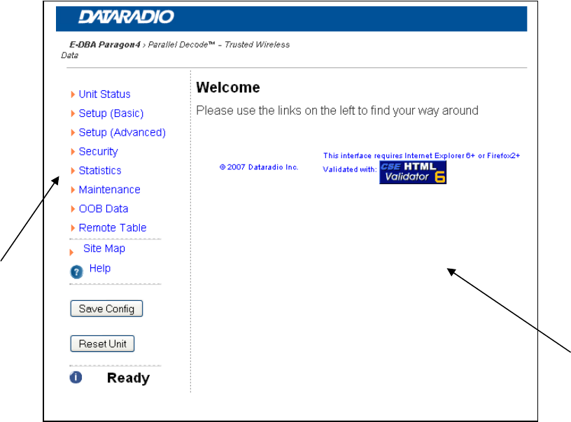
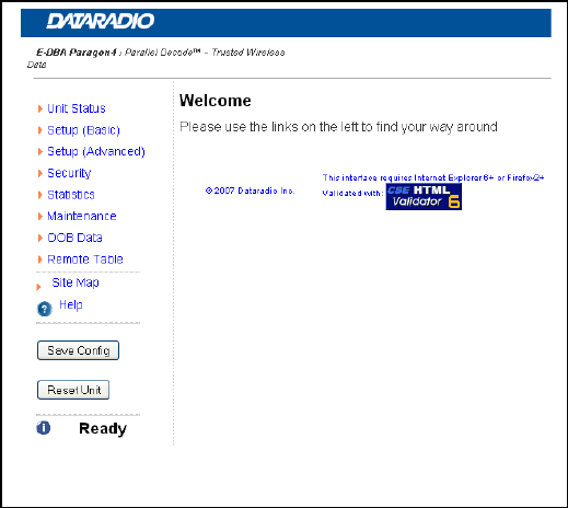
Figure 10 - Web Interface
6.1.1 Interface Setup and Status
The Paragon4 user interface is used to view and configure your network settings. Figure 10 shows the
welcome screen of the Web Interface. The screen is subdivided in two frames: the frame on the left al-
lows the user to navigate through the menus, while the main frame on the right displays the selected page.
The menu system is two-leveled; some of the top-level menus expand to offer submenus. The Site Map
link can be found right below the menus on the navigator pane. Help is available for each page displayed
in the main frame. It can be accessed at all times by clicking the Help icon. The remaining buttons on the
bottom of the Navigator frame are used to save your configurations and reset the unit.
Navigator
Frame
Main
Frame
Preliminary
001-2019-500 Rev 0 Paragon4 – UHF, 700 & 800MHz User Manual
19
6.3 IP Network Configuration
Paragon4 base stations feature two Ethernet interfaces (ETH1 and ETH2) and one RF interface. ETH1 is
commonly connected over the backhaul to the Host network. ETH2 is commonly used for a local connec-
tion for setup purposes.
6.3.1 Default IP Settings
Paragon4 radio modem supports the Router (IP Forwarding) mode
6.3.1.1 ETH1
• MAC: 00:0A:99:XX:YY:ZZ
• IP ADDR: 192.168.202.1
• NETMASKS: 255.255.255.0
• Default Gateway: 0.0.0.0
• DHCP Client Disabled
• RIPv2 Disabled
6.3.1.2 ETH2
• MAC: 00:0A:99:XX:YY:ZZ + 1
• IP ADDR: 192.168.203.1
• NETMASKS: 255.255.255.0
• DHCP Server Disabled
• NAT Disabled
6.3.1.3 RF Interface
• MAC: 00:XX:YY:ZZ
• IP ADDR: 10.XX:YY:ZZ
• NETMASK: 255.0.0.0
• Encryption Disabled
Keep the RF IP setting as is, providing customer is not using the 10.0.0.0 IP network.
Enable RIPv2 on Base station.
6.3.2 Configuring Local PC
1. ClickStartÎSettingsÎControlPanelÎNetworkandDial‐upConnection
2. ClickontherelevantLocalAreaConnection
3. OntheLocalAreaConnectionStatusscreen,clickProperties
4. OntheLocalAreaConnectionPropertiesscreen,scrolltheListBoxuntil“InternetProtocol
(TCP/IP)”ishighlighted,clickProperties
5. OntheInternetProtocol(TCP/IP)Propertiesscreen,followeithermethodbelow:
6. IfusingETH2(SetupLAN),select“ObtainanIPaddressautomatically”
7. Select“UsethefollowingIPaddress”ÎEnter192.168.202.2(ifETH2enter192.168.203.2)in
theIPaddressfieldÎ255.255.255.0intheSubnetmaskÎLeavetheDefaultgatewayblank.
8. ClicktheOKbutton
9. StepsabovespecificallyapplytoMS‐Windows2000.ModifyasnecessaryfortheOSyouarerun‐
ning
Preliminary
001-2019-500 Rev 0 Paragon4 – UHF, 700 & 800MHz User Manual
20
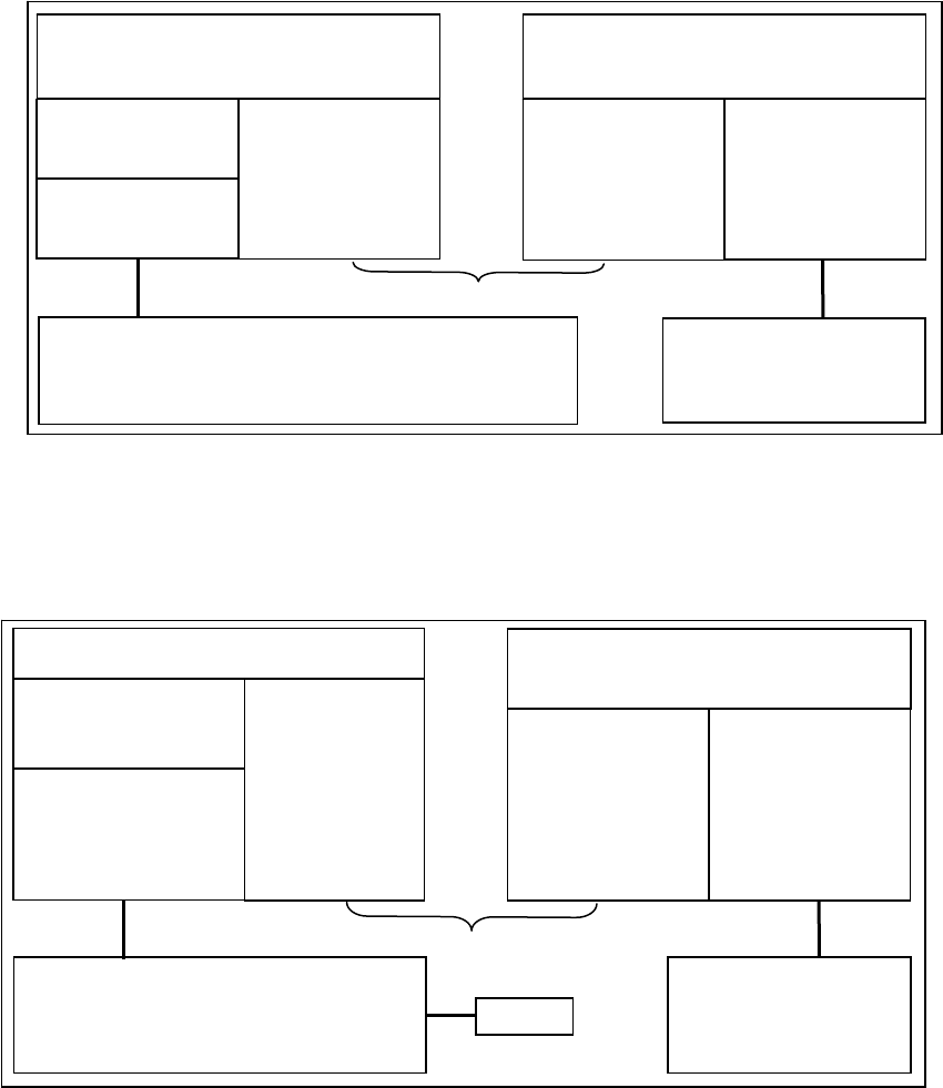
6.3.3 IP Network Settings (Paragon4 connected directly to Host)
Figure 11 below illustrates Paragon4 base station settings. In Setup (Advanced) Î LAN (IP), set ETH1
and ETH2 IP addresses and netmask of both Base and Mobile(s).
Keep the RF IP setting as is, providing customer is not using the 10.0.0.0 IP network.
Add routes in the Host to reach the RF Network (route add…)
In the illustration, Host and PC are part of different IP subnet
Figure 11 - IP Network Settings in Router Mode (with Host)
6.3.4 IP Network Settings (Paragon4 connection to Router)
Figure 12 below illustrates Paragon4 base station settings. In Setup (Advanced) Î LAN (IP), set the
ETH1 and ETH2 IP addresses and netmask of both Base and Mobile(s).
In the illustration, Host and PC are part of different IP subnet.
Figure 12 - IP Network Settings in Router Mode (with Router)
On a PC running MS-Windows with an existing LAN connection, connect either to the ETH1 or to ETH2
RJ-45 input of the Paragon4 base station.
Paragon4 Base
SETUP:
Eth2 IP: 192.168.203.1
MASK: 255.255.255.0
RF IP: 10.0.0.1
MASK: 255.0.0.0
Mobile
DHCP Server
RF IP: 10.0.0.2
MASK: 255.0.0.0
Eth1 IP: 192.168.201.1
MASK: 255.255.255.0
RF Network
Host
IP: 192.168.202.2
MASK: 255.255.255.0
route add 10.0.0.0 mask 255.0.0.0 192.168.202.1
PC
DHCP Client
DATA:
Eth1 IP: 192.168.202.1
MASK: 255.255.255.0
Paragon4 Base
SETUP:
Eth2 IP: 192.168.203.1
MASK: 255.255.255.0
RF IP: 10.0.0.1
MASK: 255.0.0.0
Mobile
DHCP Server
NAT
RF IP: 10.0.0.2
MASK: 255.0.0.0
Eth1 IP: 192.168.201.1
MASK: 255.255.255.0
RF Network
Route
r
IP: 192.168.202.2
MASK: 255.255.255.0
route add 10.0.0.0 mask 255.0.0.0 192.168.202.1
PC
DHCP Client
DATA:
Eth1 IP: 192.168.202.1
MASK: 255.255.255.0
Default Gateway:
192.168.202.2
Host
Preliminary
001-2019-500 Rev 0 Paragon4 – UHF, 700 & 800MHz User Manual
21
6.4 Web Server Login
In an Internet browser, enter http://92.168.20x.1 (where x is 2 for the ETH1 Data port and 3 for the ETH2
Setup port). This will bring up the Paragon4 product login page (Note: It may take 30 seconds from ini-
tial power-up for the homepage to be available.) Login to the device.
For an initial installation, enter a User Name of 1 to 15 characters and the default Password
ADMINISTRATOR (upper case letters). Click OK. The web interface “Welcome” screen opens (Figure
13).
For subsequent access to the Paragon4 unit, use the User Name and Password that you will have confi-
gured (as detailed in section 6.9.1).
Notes:
User Name field can be left blank. It only serves to identify the person gaining ace ss.
Password is common and affects all User Name entries.
Figure 13 - Web User Interface – Welcome Screen
Preliminary
001-2019-500 Rev 0 Paragon4 – UHF, 700 & 800MHz User Manual
22
6.5 Web Interface
The Paragon4 user interface (Figure 13) is used to view and configure your network settings.
To navigate, use the top-level menus on the left, some of which expand to offer submenus, and display
the first submenu in the right-hand frame. Click the current submenu entry to refresh the right-hand
frame. The tables starting at section 6.6.1 below list action of each function. The interface main screen
lists available selections for the selected menu or presents instructions.
Notes:
At any time, click the Help icon in the navigation pane to open a help text relating to the window
being displayed.
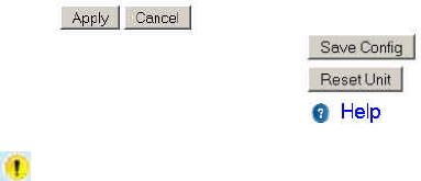
6.5.1 Apply, Cancel, Save Config, and Reset Unit Buttons & Help Icon
Several submenus have “Apply” and “Cancel” buttons.
The navigation area has “Save Config”, “Reset Unit” but-
tons and a Help icon.
If you “Apply” changes to any parameters marked you will need to do a “Save Config” and a “Re-
set Unit”.
When making an entry into a dialog box, click on Apply when satisfied to temporarily apply the value(s)
entered to the relevant parameter(s). If not satisfied, click on Cancel button to restore to the value(s)
present before a change was made.
Note: Cancel command only affects the dialog boxes or option buttons in the opened window.
If needed, go to other submenu(s) and make more entries. Click Apply before leaving each window.
When finished, click the Save Config button to make all changed entries permanent.
Notes:
“Apply” writes to RAM, thus failure to use the “Apply” command button before leaving a web page
will result in the loss of temporarily entered selections, addresses, and values.
“Save Config” writes in flash, thus failure to use the “Save Config” command button will result in
the loss of temporarily entered parameters. A “Reset” is required to make flash changes take effect.
Click on Save Config button:
• If there are changes to be saved, saving occurs right away
• If there are no changes to be saved, a pop-up window prompts user to confirm saving anyway
Click on “Reset Unit” button:
• If there are changes to be saved, a window prompts user to confirm resetting.
• If there are no changes to be saved, resetting occurs right away
A “Station Reset” 20-second timer counts down while the status reports: “Working…”
When done, the status reports: “Ready”.
Preliminary
001-2019-500 Rev 0 Paragon4 – UHF, 700 & 800MHz User Manual
23
6.6 Unit Status
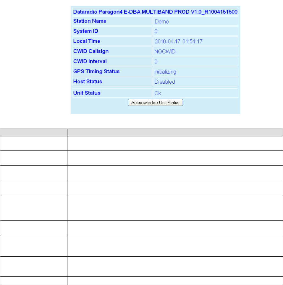
6.6.1 Unit Status ► General
Displays values that identify the unit and show its basic operating condition.
Figure 14 - Unit Identification and Status
Item Description
Banner Displays Paragon4 software revision information retrieved from the connected unit. Have
this information handy if contacting Dataradio support.
Station Name Displays name of connected unit.
Configured under Setup Basic Î General Î Station Name
System ID Displays System’s unique identification number
Configured under Setup Basic Î General Î System ID
Local Time 24-hour clock format display of the GMT time and date adjusted to the specified time zone.
Configured under Setup Advanced Î Time Source Î SNTP
CWID Callsign
Continuous wave ID - Way of sending FCC license ID using Morse code.
Continuous Wave Identification uses Morse Code to automatically send out the station ID
periodically to identify the owner of the transmitting base station. This satisfies the require-
ments of the FCC.
CWID Interval Interval between CWID messages in minutes.
Zero = never.
Unit Status
Normally displays “Ok” in the message area.
Displays various warnings or messages in the event of hardware failure,
If indications persist, have the status information handy if contacting Dataradio support.
Host Status
Status of the link to the specified Host, if configured in Setup (Advanced) → Roaming →
Host Link Active.
Values displayed are Disabled, Reachable, and Unreachable.
Acknowledge Unit Status Press this button to clear the Unit Status message area.
Preliminary
001-2019-500 Rev 0 Paragon4 – UHF, 700 & 800MHz User Manual
24
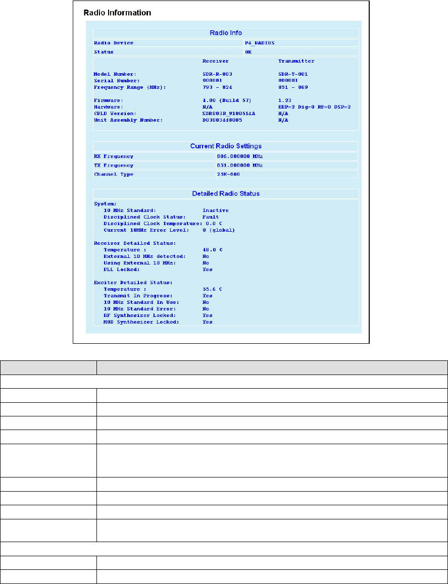
6.6.2 Unit Status ►Radio Info & Status
Radio Information read-only table displays the Paragon4 radio information retrieved from the connected
radio modules. Have this information handy if contacting CalAmp. Paragon4 models that have both re-
ceivers combined into a single module will show the same information in the RX main and RX diversity
rows.
Figure 15 - Unit Status - Radio Information
Item Description
Radio Info
Radio Device Identifies the installed radio module’s model
Status Identifies the status of the active radio (Ok or Fault –module is down)
Model Number Indicates the model of the receiver/transmitter
Serial Number Unique number assigned to the receiver/transmitter at time of manufacture
Frequency range Shows the receive/transmit frequency range the unit can synthesize. For information on
the frequency ranges for each radio model, see Section 8, Specifications.
Firmware Identifies the version number of the firmware installed on the receiver/transmitter
Hardware Identifies the version number of the hardware installed (receiver/transmitter)
CPLD Version Identifies the version number of the CPLD (Complex Programmable Logic Device)
Unit Assembly Num-
ber Identifies Unit Assembly Number
Current Radio Settings
RX Frequency Shows the current (or last) receive frequency
TX Frequency Shows the current (or last) transmit frequency
Preliminary

001-2019-500 Rev 0 Paragon4 – UHF, 700 & 800MHz User Manual
25
Channel Type Shows the current (or last) channel type
Detailed Radio Status
System 10 MHz Standard - 10 MHz reference- Active (10 MHz signal present) or Inactive (10 MHz
signal not present or not within specification)
Disciplined Clock
Status
Internal 10 MHz reference status
Locked = The Disciplined Clock has acquired GPS lock and is providing a valid
10MHz source.
Unlocked = The Disciplined Clock has lost its GPS lock and is waiting for GPS
signal reacquisition. The 10 MHz source is still valid.
Never been
locked yet = After power up, the Disciplined Clock has not acquired its first GPS
lock yet. The 10 MHz source is not valid.
Fault = The Disciplined Clock cannot provide a valid 10 MHz source for one
of the following reasons:
1. There was a hardware or firmware initialization error.
2. The GPS has failed to acquire any satellite signal within
the allowed time period (Check GPS antenna)
10 MHz source
unreliable = The Disciplined Clock has lost its GPS lock for too long and cannot
guaranty the accuracy of its 10MHz source anymore (check GPS
antenna). This message can also appear if the VCO on the Disci
plined Clock circuit is no longer within specification due to age,
damage or extreme environmental conditions.
Disabled = The Disciplined Clock is not active. The 10MHz source from this cir
cuit is unreliable or an external source is provided.
Disciplined Clock
Temperature
Displays Disciplined Clock temperature in degrees Celsius.
Note: Displays "N/A" if the Disciplined Clock's state is "Disabled".
Receiver Detailed Status
Temperature Receiver's temperature in degrees Celsius.
External 10 MHz de-
tected Yes (10 MHz signal in use by the receiver), No (10 MHz signal not in use by the receiver)
Using External 10
MHz Yes, No (10 MHz signal is in use by the receiver)
PLL Locked Yes, No (RF synthesizer is phase-locked-loop to internal 17.5MHz or external 10MHz
reference signal.)
Exciter Detailed Status
Temperature Exciter's temperature in degrees Celsius
Transmit in progress Yes, No
10 MHz Standard in
use Yes (10 MHz signal in use by the exciter), No (10 MHz signal not in use by the exciter)
10 MHz Standard
Error
Yes, No (The exciter will report a failure when the 10 MHz signal is present initially and
removed after system initialization.)
RF Synthesizer
Locked
Yes, No (May signify RF synthesizer device error. Contact support for additional infor-
mation.)
MOD Synthesizer
Locked
Yes, No (May signify MOD synthesizer device error. Contact support for additional in-
formation.)
Preliminary
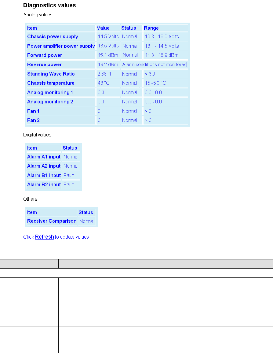
001-2019-500 Rev 0 Paragon4 – UHF, 700 & 800MHz User Manual
26
6.6.3 Unit Status ►Diagnostics
Figure 16 - Unit Status – Diagnostics
Item Description
Analog Values
Chassis power supply Displays chassis power supply voltage
Power amplifier pow-
er supply
Displays power amplifier power supply voltage. Available only if extra wires are added
from the PA +/- supply terminals and the P4 backplane TB1-1 / TB1-2 terminals.
Forward power
Displays forward power when the optional external power sensor assembly (p/n 030-
03547-xxx) is installed.
Note: Power measurement units (dBm or Watts) are user defined under Setup Advanced
►User Settings
Reverse power
Displays reverse power when the optional external power sensor assembly (p/n 030-
03547-xxx) is installed.
Note: Power measurement units (dBm or Watts) are user defined under Setup Advanced
►User Settings
Preliminary

001-2019-500 Rev 0 Paragon4 – UHF, 700 & 800MHz User Manual
27
Standing Wave Ratio
Displays Standing Wave Ratio. Standing Wave Ratio (SWR) is computed as follows:
Note: SWR is always computed-based on the forward and reverse power values in Watt,
regardless of the power measurement unit chosen for display.
Chassis temperature
Displays the internal unit chassis temperature. That temperature is usually 10 to 15oC
higher than ambient room temperature. Default range: 15 to 40oC
Note: Temperature measurement units are user defined under Setup Advanced ►User
Settings
Analog monitoring 1 Generic Analog input (0 – 30VDC)
Displays user supplied analog input’s measurement values
Analog monitoring 2 Generic Analog input (0 – 30VDC)
Displays user supplied analog input’s measurement values
Fan 1 Fan speed monitoring signal. Analog sinusoidal input (0-5VDC) or digital TTL input (de-
tection threshold, low = 0.4V max and high = 2.4V min).
Fan 2 Fan speed monitoring signal. Analog sinusoidal input (0-5VDC) or digital TTL input (de-
tection threshold, low = 0.4V max and high = 2.4V min).
Digital Values
Alarm A1 input
Generic Alarm inputs. Programmable active high or low polarity. Safe voltage range -0.1V
to 30V.
When active high (low):
Voltage guaranteed to be detected as an alarm: 2.4V min (0.4V max).
Voltage guaranteed not to be detected as an alarm: 0.4V max (2.4V min).
Alarm A2 input
Alarm B1 input
Alarm B2 input
Status
For all digital and analog alarms displays alarm status: Normal or Fault.
For Forward Power and Standing Wave Ratio (SWR) displays “Transmitter off” when the
transmitter is off. Disregard the diagnostic value for SWR, Forward Power, and Reverse
Power if the transmitter is off.
Range
Displays range of values for all monitored analog diagnostic parameters.
User-configurable under Setup (Advanced) ►Diagnostics.
Recommended nominal ranges are:
Chassis Power Supply 10.8-16.0 Volts
Power Amplifier Power Supply 13.1-14.5 Volts (with Crescend PA)
Forward Power (700 & 800 MHz) 15. 0-77.0 Watts
Forward Power (UHF) 15. 0-110.0 Watts
Preliminary
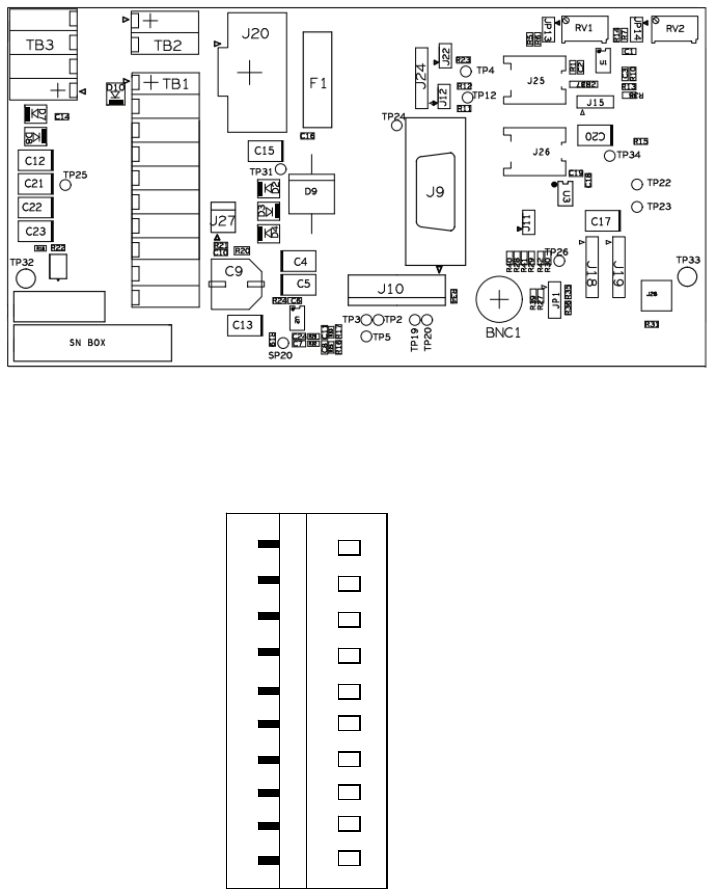
001-2019-500 Rev 0 Paragon4 – UHF, 700 & 800MHz User Manual
28
6.6.3.1.1 External Analog/Digital Inputs Monitoring
The user can connect and monitor two external analog and four external digital inputs to the backplane
TB1 connector terminals (
Figure 17 and Figure 18).
Figure 17 - Backplane -TB1 connector
Figure 18 - TB1 connector
An external analog device’s voltage must not exceed 30 Volts. The default units of measure used for
monitoring an external device are volts. It is possible to change the default units by creating a look-up
table for the desired unit of measure. This look-up table is created following the guidelines in section
6.8.10.1 and is uploaded into the Paragon4 unit using FTP transfer. Refer to section 6.8.10
TB1
Analog monitoring 2
Analog monitoring 1
Alarm B2 in
p
ut
Alarm B1 in
p
ut
Alarm A2 in
p
ut
Alarm A1 in
p
ut
Preliminary
001-2019-500 Rev 0 Paragon4 – UHF, 700 & 800MHz User Manual
29
Preliminary
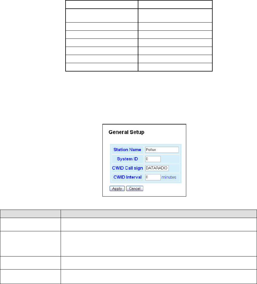
001-2019-500 Rev 0 Paragon4 – UHF, 700 & 800MHz User Manual
30
Note 1: TB1 connector labeling differs from the actual backplane:
TB1 / Web page name(s) TB1 / Backplane name
Power amplifier power
supply
+13V8_PA
Alarm A1 input AL_A1
Alarm A2 input AL_A2
Alarm B1 input AL_B1
Alarm B2 input AL_B2
Analog monitoring 1 AN1
Analog monitoring 2 AN2
6.7 Setup (Basic)
6.7.1 Setup (Basic) ► General
Used to set four basic operating fields on the connected unit.
Figure 19 - Setup (Basic) – General Setup
Item Description
Station Name Station name identifier – Enter string up to forty characters in length (letters and/or
numbers)
System ID
Factory default ID is zero. To prevent collision and to minimize interference from re-
mote systems that may be present on the same frequency, Dataradio recommends
changing the System ID to some other value unique to each network.
Upper limit is 255
CWID Call sign Historically called “Continuous wave ID” – Way of sending FCC license ID using
Morse code
CWID Interval Interval between CWID messages in minutes
Zero = never.
Preliminary
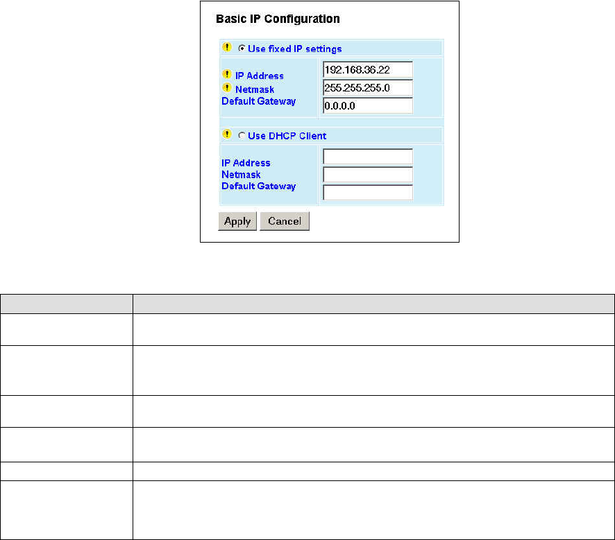
001-2019-500 Rev 0 Paragon4 – UHF, 700 & 800MHz User Manual
31
6.7.2 Setup (Basic) ► IP (Basic IP Configuration)
Sets the IP characteristics of the primary, or only, Ethernet port (ETH1).
Figure 20 - Setup (Basic) – Basic IP Configuration
Item Description
Use fixed IP settings Creates a fixed TCP/IP address connection. You may need to ask your network adminis-
trator for the appropriate IP settings.
IP Address
Set to valid unique IP address for each individual unit.
Factory default is 192.168.202.1 for all Paragon4 units connected to their ETH1 port.
For ETH2 configuration, see Setup Advanced Î LAN IP
Netmask Set to valid IP netmask for each individual unit (may be same or different depending on
customer’s IP network topology).
Default Gateway Set to valid Default Gateway.
May change for different groups or locations
Use DHCP Client Dynamic Host Configuration - Dynamically assigns an IP address
IP Address
Netmask
Default Gateway
These three read-only fields display the IP addresses obtained from the DHCP Server
For ETH2 configuration, see Setup Advanced Î LAN IP
Preliminary
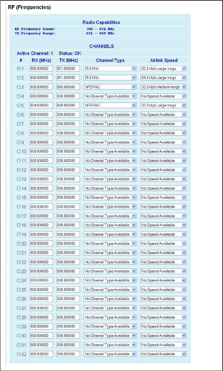
001-2019-500 Rev 0 Paragon4 – UHF, 700 & 800MHz User Manual
32
6.7.3 Setup (Basic) ► RF (Frequencies)
Figure 21 - RF (Frequencies)
Preliminary

001-2019-500 Rev 0 Paragon4 – UHF, 700 & 800MHz User Manual
33
Item Description
Radio Capabilities
RX Frequency Range Shows the receive frequency range the unit can synthesize
Typically: Rx 792 – 824
TX Frequency Range Shows the transmit frequency range the unit can synthesize
Typically: Tx 763 – 776
Channels Table Set Up
Active Channel Select one at a time (from 1 to 32)
Status Displays channels setup status.
OK or Invalid (invalid RX/TX selection or receiver/transmitter is down)
RX (MHz)
TX (MHz)
Enter RX and TX frequency in MHz in the appropriate dialog box.
Note: The RF frequencies entered must match the corresponding RF frequency on the
GeminiG3 mobile radios.
Entries must fall within the Min and Max indicated on top of the page (erroneous entries
will be highlighted in red) and must be multiples of corresponding frequency step (6.25
KHz for 700/800 MHz frequency ranges or 5, 6.25, or 10 KHz for UHF frequency ranges).
Dataradio recommends (in North America) offsetting the TX column frequency by +30
MHz for 700 MHz frequency ranges, by -45 MHz for 800 MHz frequency ranges, or by +/-
5MHz for UHF frequency ranges.
E.g.:
Assuming:
Min Rx=851.000 000 MHz
Max Rx=869.000 000 MHz
Offset=-45.000 000 MHz
If selection for a channel's RX was:
Rx (MHz)=853.037 500
then its corresponding TX would be computed as:
Tx (MHz)=853.037 500+(-45.000 000)=808.037 500
Note: Exercise caution when entering RF frequencies. Paragon4 base station will reject
any entry with a wrong frequency step and will transmit at the previous correct entry or
return to its default (factory-configured) RF frequency setting.
Airlink Speed
Lists the choice of Airlink speeds, the nominal speed at which data packets are trans-
mitted over-the-air in E-DBA.
The mobile will automatically adapt to the base station.
e.g.: At 800 MHz Full Channel, the choices are:
64kb/s short messages, medium messages, large messages
48kb/s short messages, medium messages, large messages
43.2kb/s short messages, medium messages, large messages
32kb/s short messages, medium messages, large messages
Airlink speeds available depend on the channel type selected (from 16 kb/s to 128 kb/s).
Note: The channel table settings take effect immediately after Apply is clicked.
Preliminary
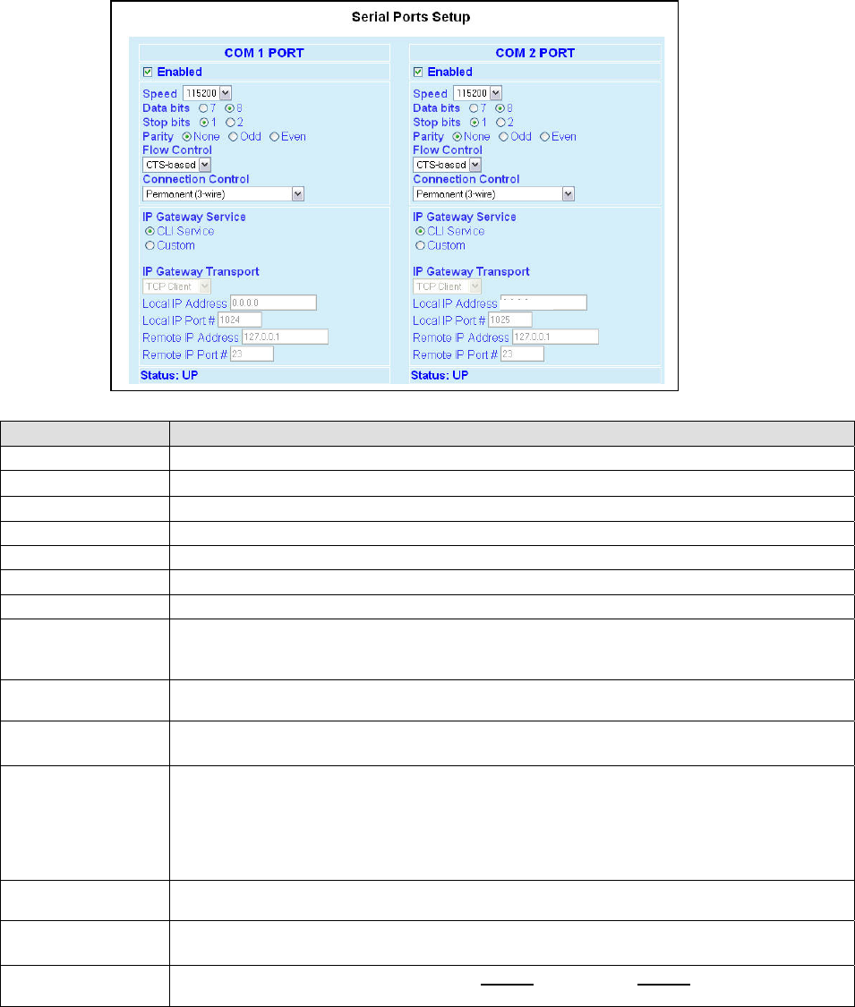
001-2019-500 Rev 0 Paragon4 – UHF, 700 & 800MHz User Manual
34
6.7.4 Setup (Basic) ► Serial Ports Setup
The Paragon4 base station serial ports can be logically connected to local and remote services to aid in
configuration and troubleshooting, or they can be connected to a remote Host application or even to the
serial port of a remote unit.
Figure 22 - Setup (Basic) – Serial Ports Setup
Item Description
Enabled Independent check boxes to activate COM-1 PORT and/or COM-2 PORT
Speed Select 300, 1200, 2400, 4800, 9600, 19200, 38400, 57600, 115200 Baud Rate
Data Bits Number of bits making up the data word. Set according to Host configuration. Default is 8.
Stop Bits Number of bits at the end of the data word. Default is 1.
Parity Added to identify the sum of bits as odd or even. Default is None.
Flow Control Select None or CTS-based (depends on connected device)
Connection Control Select Permanent (3-wire) or Switched (DTR bringup/teardown) (RTU dependent)
IP Gateway Service
Select one of:
CLI Service (Command line interface) RS-232 connection to Host PC (Default = SETUP)
Custom – Choosing Custom enables the IP Gateway Transport configuration
IP Gateway Transport Available only if IP Gateway Service selection is Custom, choose the socket connection mode
from the drop-down list box choices of TCP Server, TCP Client, or UDP.
Local IP Address Valid unicast or multicast IP address, including the local Loopback interface address.
Default local IP address is set to 0.0.0.0 and can be changed dynamically without a unit reset.
Local IP Port
For TCP Client and UDP socket connections, set to any value between 1 and 65535.
For TCP Server socket connections, set to any value between 1 and 65535 but must not be set to
one of the following values or fall within the following ranges of values: 20, 21, 23, 123, 520, 5002,
6254 to 6299, 7000 to 7100. Otherwise, the parameter configuration will be accepted, but no sock-
et connection will be established to accept connection from remote endpoints.
Default local port value is set to 1024 and can be changed dynamically without a unit reset.
Remote IP Address Default remote IP address is the Loopback interface address, 127.0.0.1 and can be changed dy-
namically without a unit reset
Remote IP Port For socket connection modes (TCP active, UDP), set to any value between 1 and 65535.
Default local port value is 23 and can be changed dynamically.
Status Can be UP, READY, or DOWN. Click on the “Refresh” word in the “(Refresh this frame to confirm
“Status”) sentence to update Status condition.
10.255.255.25
Preliminary
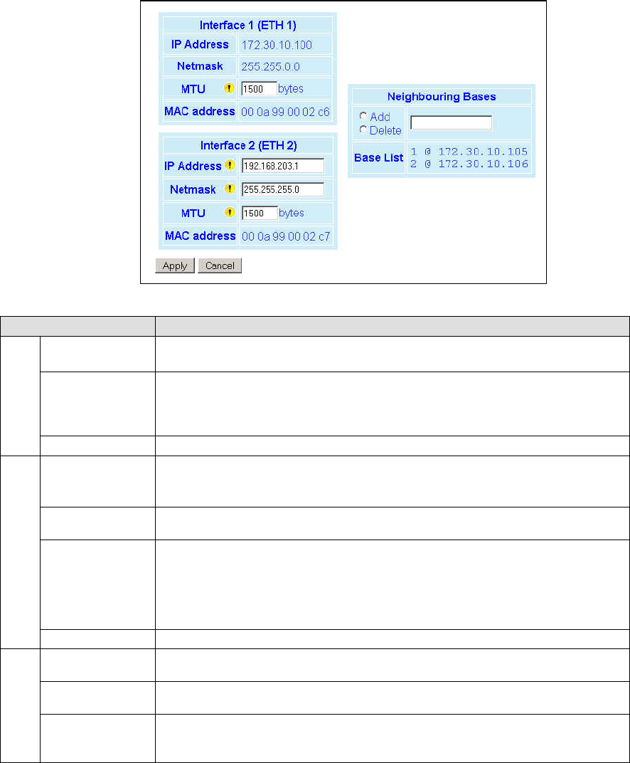
001-2019-500 Rev 0 Paragon4 – UHF, 700 & 800MHz User Manual
35
6.8 Setup (Advanced)
6.8.1 Setup (Advanced) ► LAN (IP)
Allows the setting of IP characteristics beyond those set in Setup (Basic) Î IP
When a mobile registers with a new base, the base may send a message to each of its neighbor to
assure that their Internet tables are up-to-date. Up to 32 neighbors can be entered. An empty or
incomplete table may cause IP routing problems when the mobile roams.
Figure 23 - Advanced IP Configuration - LAN (IP)
Item Description
Interface 1 (ETH1)
IP Address
Netmask
Read-only fields showing IP Address and Netmask defined earlier in Setup (Basic)Î
Basic IP.
MTU
Ethernet Interface MTU - Default 1500. – For optimal performance, set at 1500.
Entering a value lower than 1500 may reduce system performance. Flexibility of us-
ing lower values may be useful in testing or for particular operational conditions.
Range is 576 to 1500.
MAC address Ethernet Interface MAC address in HEX format (factory-set).
Interface 2
(ETH2)
IP Address
Set to valid unique IP address for each individual unit.
Factory default is 192.168.203.1 for all Paragon4 units connected to their ETH2 port.
For ETH1 configuration, see Setup Basic Î Basic IP Configuration
Netmask Set to valid IP netmask for each individual unit (may be same or different depending
on customer’s IP network topology).
MTU
Ethernet Interface MTU - Default 1500. – For optimal performance, set at 1500.
Entering a value lower than 1500 may reduce system performance. Flexibility of us-
ing lower values may be useful in testing or for particular operational conditions.
Range is 576 to 1500.
MAC address Ethernet Interface MAC address in HEX format (factory-set).
Neighboring
Bases
Add Type in the “Neighboring Bases” field the IP address in dot decimal format of the
base to be added to the neighboring “Base List” table.
Delete Type in the “Neighboring Bases” field the IP address in dot decimal format of the
base to be deleted from the neighboring “Base List” table.
Base List
Read-only listing. Dynamic window expands downward as needed to show all ad-
dresses added to the list or shrinks as addresses are removed.
Shows “Table is empty” if no address is present in the Base List.
Preliminary
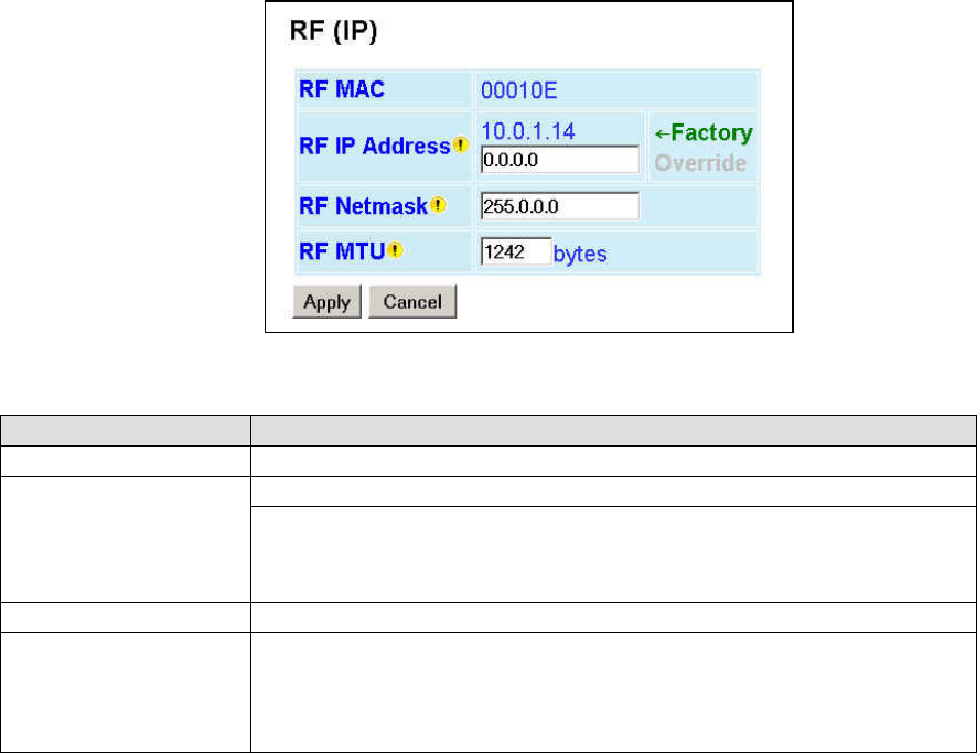
001-2019-500 Rev 0 Paragon4 – UHF, 700 & 800MHz User Manual
36
6.8.2 Setup (Advanced) ► RF (IP)
At the time of manufacture, each Paragon4 base station and GeminiG3 radio modem is provided with a
unique MAC address for its Ethernet and RF interfaces. These addresses cannot be changed. The RF in-
terface is also provided with a unique Factory RF IP address. If this IP address conflicts with any existing
IP network, it can be overridden.
Figure 24 - Advanced IP Configuration - RF (IP)
Item Description
RF MAC RF Interface MAC address in HEX format (factory-set).
RF IP Address
Displays factory-assigned address: nnn.nnn.nnn.nnn “Factory”
Entering 0.0.0.0 sets the RF IP Address to the factory default and highlights the
“Factory” name (active address)
Entering nnn.nnn.nnn.nnn (RF IP Address of your choice) overrides the factory
default and highlights the “Override” name (active address)
RF Net Mask Set to valid common IP netmask for all units within a Paragon4 network
RF MTU
RF Interface MTU - Default 1242. – For optimal performance, set at 1242.
Entering a value other than 1242 may reduce system performance, especially if set
to a higher value. Flexibility of using other values may be useful in testing or for
particular operational conditions.
Range is 576 to 1500.
Preliminary
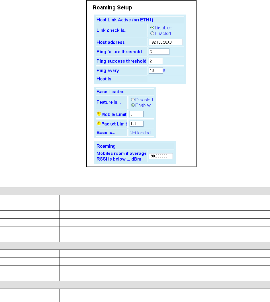
001-2019-500 Rev 0 Paragon4 – UHF, 700 & 800MHz User Manual
37
6.8.3 Setup (Advanced) ► Roaming
The “Host Link Active” feature allows a base to assure the communication backhaul is operating. If not,
the base indicates to mobiles on the channel that they should promptly roam to another base
The “Base Loaded” feature monitors the amount of network traffic during the previous 10-second period.
If there are more than a certain number of mobiles actively sending data and the channel is occupied
above a certain percentage, then the base indicates that a portion of the registered mobiles should roam to
other bases, until channel loading falls below the thresholds.
Figure 25 - Advanced IP Configuration – Roaming
Host Link Active (on ETH1)
Link check is… Disabled (Default), Enabled
Host address IP address of a router/host to be pinged periodically
Ping failure threshold This many failed pings in a row are needed to mark the “Host is…” field as “Unreachable”
Ping success threshold This many successful pings in a row are needed to mark the “Host is…” field as” Reachable”
Ping every How often to send a ping
Host is … Current status of the host link (blank if disabled)
Base Loaded
Feature is… Disabled, Enabled
Mobile Limit Minimum number of active mobile before channel can be considered “Loaded”
Packet Limit Minimum percentage of data capacity before channel can be considered “Loaded”
Base is… Current status of the base (blank if disabled)
Roaming
Mobiles roam if average
RSSI is below…
Currently registered mobiles will roam if average signal strength of all synchronization pack-
ets received in the last 20 seconds is below this value
Preliminary
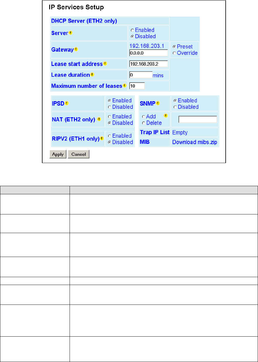
001-2019-500 Rev 0 Paragon4 – UHF, 700 & 800MHz User Manual
38
6.8.4 Setup (Advanced) ► IP Services
Figure 26 - Advanced IP Configuration – IP Services Setup
Item Description
Server
DHCP Server Disabled, Enabled (Default). The Dynamic Host Configuration Proto-
col provides a framework for passing configuration information
e.g.: IP address to Hosts (i.e. PC/RTU) on a TCP/IP network.
Gateway
Gateway address handed out by the DHCP Server to the DHCP Client. The default
value is set to the IP address of the Ethernet 2 interface. If the gateway is set to
0.0.0.0, no gateway address will be handed out by the DHCP Server.
Lease Start Address
Pool of addresses allocated for DHCP purpose. If a unit is configured as DHCP
Server, this field represents the start IP address pool managed by the DHCP
Server. Normally, Paragon4 automatically calculates the Lease Start Address
(equal to Ethernet IP Address plus one).
Lease Duration
The period over which the IP Address allocated to a DHCP client is referred to as
a “lease”. Lease Duration is the amount entered in minutes.
A value of “0” indicates an infinite lease.
Maximum number of leases Maximum number of DHCP client(s) a unit can serve.
IPSD
IP Services Delivery – Disabled (Default), Enabled.
Allows or disallows the generation of locally provided IP Services such as online
diagnostics, alarms, etc…
NAT (ETH2 only)
Network Address Translation - Disabled, Enabled (Default)
NAT technology is a method by which IP addresses are mapped from one address
space to another. In Paragon4, it is normally used on the WAN side of an IP net-
work to hide local IP addresses from an external IP network (i.e. Internet).
See section 4.7.3.4.1 for a more detailed description.
RIPV2 (ETH1 only)
Router Information Protocol v2 - Disabled, Enabled (Default)
When Enabled, mobile registration causes RIPv2 report to be sent to the backhaul
router(s) so that the infrastructure will route all packets for this mobile through
this base station.
Preliminary

001-2019-500 Rev 0 Paragon4 – UHF, 700 & 800MHz User Manual
39
Item Description
SNMP
Simple Network Management Protocol – Disabled, Enabled (Default)
SNMP provides means to monitor, collect, and analyze diagnostic information.
Enabling SNMP allows the MIB (Management Information Base) in the Paragon4
to be viewed using an external MIB browser or network management software.
Trap IP List
After reset, the Paragon4 sends a WARMSTART trap to all of the IP addresses
defined in the Trap IP list. It signifies that the system has started.
To add an address to the Trap IP List: Select Add and type the new IP address to
be added to the read-only Trap IP list. The window will expand downward to show
all addresses in the list.
To delete an address to the Trap IP List: Select Delete and type the new IP ad-
dress to be deleted from the read-only Trap IP list.
MIBS
Management Information Base -used to assemble and interpret SNMP messages.
The Dataradio Paragon4 MIB is bundled with each unit's firmware. Click "Down-
load mibs.zip" and a pop-up dialog box will appear in your browser asking you to
open or save the file to your PC. Save the zip file to a desired location. Unzip the
contents of mibs.zip file to a location where your SNMP manager can find it.
Note: SNMP must be enabled in order for the host PC SNMP manager to work.
Preliminary
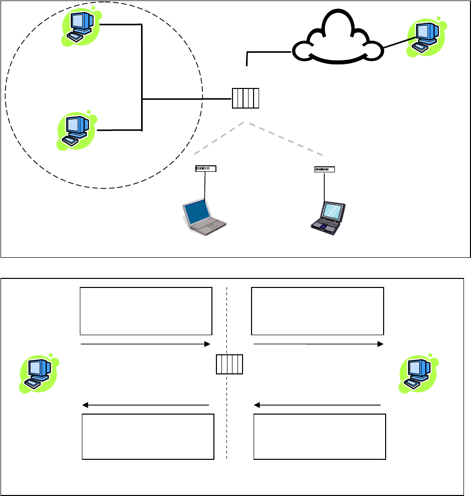
001-2019-500 Rev 0 Paragon4 – UHF, 700 & 800MHz User Manual
40
6.8.4.1 NAT on the Base Unit (Paragon4)
The purpose of the “Network Address Translation” (NAT) protocol is to hide a private IP network
from a public network. The mechanism serves both as a firewall function and to save IP address space.
When NAT is enabled on the P4, the private network (from the point of view of the Base station) is the IP
network associated to the Ethernet 2 interface.
Figure 27 - NAT Enabled on Paragon4
Figure 28 - Paragon4 - Example 1
In example 1, Management Host 1 sends Packet (1) to External Host 1. Since the source IP address of
Packet (1) comes from the private network, it gets replaced by the IP address of the Ethernet 1 interface of
the Base station.
External Host 1
200.1.1.1/24
RF Network
Public Network
(External Network + RF Network +
Mobile 1 Network + Mobile 2 Network)
Mobile 1 Network
Base
(Paragon4)
Ethernet 1
192.168.1.1/24
Mobile Host 1
173.30.1.2/24
Mobile (G3)
Mobile (G3)
Ethernet 2
172.30.1.1/24
RF 10.0.1.2/24 RF 10.0.1.3/24
173.30.1.1/24 174.30.1.1/24
Mobile Host 2
174.30.1.2/24
Mobile 2 Network
External
Network
Management Host 1
172.30.1.2/24
Management Host 2
172.30.1.3/24
Private Network
172.30.1.0/24
RF 10.0.1.1/24
1
Packet (1)
Source Address 172.30.1.2
Destination Address 200.1.1.1
2
Packet (1)
Source Address 192.168.1.1
Destination Address 200.1.1.1
172.30.1.1/24 192.168.1.1/24
Paragon4
(NAT Enabled)
Management Host 1
172.30.1.2/24
External Host 1
200.1.1.1/24
Private network (172.30.1.0/24) Public network (External)
3
Packet (2)
Source Address 200.1.1.1
Destination Address 192.168.1.1
4
Packet (2)
Source Address 200.1.1.1
Destination Address 172.30.1.2
Preliminary
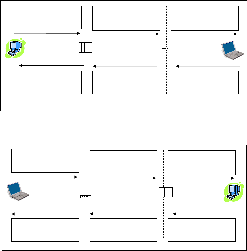
001-2019-500 Rev 0 Paragon4 – UHF, 700 & 800MHz User Manual
41
Figure 29 - Paragon4 - Example 2
In example 2, Management Host 1 sends Packet (1) to Mobile Host 1. Since the source IP address of
Packet (1) comes from the private network, it gets replace by the IP address of the RF interface of the
Base station.
Figure 30 - Paragon4 - Example 3
In example 3, Mobile Host 1 sends Packet (1) to External Host 1. Since the source IP address of Pack-
et (1) does not come from the private network, it doesn’t get replaced by another IP address by the Base
station.
2
Packet (1)
Source Address 10.0.1.1
Destination Address 173.30.1.2
3
Packet (1)
Source Address 10.0.1.1
Destination Address 173.30.1.2
10.0.1.2/24
172.30.1.1/24
Paragon4
(NAT Enabled)
Management Host 1
172.30.1.2/24
Private Network Mobile 1 Network
4
Packet (2)
Source Address 173.30.1.2
Destination Address 10.0.1.1
5
Packet (2)
Source Address 173.30.1.2
Destination Address 10.0.1.1
RF Network
6
Packet (2)
Source Address 173.30.1.2
Destination Address 172.30.1.2
1
Packet (2)
Source Address 172.30.1.2
Destination Address 173.30.1.2
Mobile (G3)
(NAT Disabled)
10.0.1.1 /24
173.30.1.1/24
2
Packet (1)
Source Address 173.30.1.2
Destination Address 200.1.1.1
3
Packet (1)
Source Address 173.30.1.2
Destination Address 200.1.1.1
10.0.1.1/24 192.168.1.1/24
Paragon4
(NAT Enabled)
Mobile Host 1
173.30.1.2/24
External Host 1
200.1.1.1/24
Mobile 1 Network External Network
4
Packet (2)
Source Address 200.1.1.1
Destination Address 173.30.1.2
5
Packet (2)
Source Address 200.1.1.1
Destination Address 173.30.1.2
RF Network
6
Packet (2)
Source Address 200.1.1.1
Destination Address 173.30.1.1
1
Packet (2)
Source Address 173.30.1.2
Destination Address 200.1.1.1
Mobile (G3)
(NAT Disabled)
10.0.1.2/24 173.30.1.1/24
Preliminary
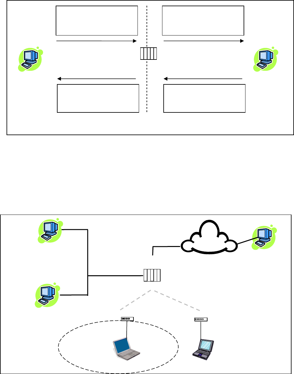
001-2019-500 Rev 0 Paragon4 – UHF, 700 & 800MHz User Manual
42
Figure 31 - Paragon4 - Example 4
In example 4, Management Host 1 sends Packet (1) to External Host 1. Even though the packet comes
from the private network, the source IP address does not. The Base station does not replace the source IP
address of Packet (1).
6.8.4.2 NAT on the Mobile Unit (GeminiG3)
When NAT is enabled on the Mobile Unit, the private network (from the point of view of the Mobile unit)
is the IP network associated to the Ethernet 1 interface.
Figure 32 - NAT Enabled on GeminiG3
External Host 1
200.1.1.1/24
RF Network
Public Network
(External Network + RF Network +
Mobile 2 Network + Management Network)
Private Network
173.30.1.0/24
Base
(Paragon4)
Ethernet 1
192.168.1.1/24
Mobile Host 1
173.30.1.2/24
Mobile (G3)
Mobile (G3)
Ethernet 2
172.30.1.1/24
RF 10.0.1.2/24 RF 10.0.1.3/24
173.30.1.1/24 174.30.1.1/24
Mobile Host 2
174.30.1.2/24
Mobile 2 Network
External
Network
Management Host 1
172.30.1.2/24
Management Host 2
172.30.1.3/24
Management Network
RF 10.0.1.1/24
1
Packet (1)
Source Address 174.30.1.2
Destination Address 200.1.1.1
2
Packet (1)
Source Address 174.30.1.2
Destination Address 200.1.1.1
172.30.1.1/24 192.168.1.1/24
Paragon4
(NAT Enabled)
Management Host 1
172.30.1.2/24
External Host 1
200.1.1.1/24
Private network (172.30.1.0/24) Public network (External)
3
Packet (2)
Source Address 200.1.1.1
Destination Address 174.30.1.2
4
Packet (2)
Source Address 200.1.1.1
Destination Address 174.30.1.2
Preliminary
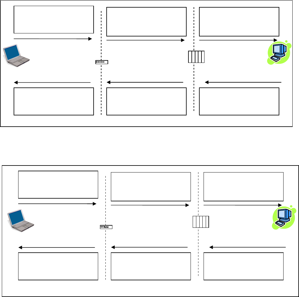
001-2019-500 Rev 0 Paragon4 – UHF, 700 & 800MHz User Manual
43
Figure 33 - GeminiG3 - Example 1
In example 1, Mobile Host 1 sends Packet (1) to External Host 1. Since the source IP address of Pack-
et (1) comes from the private network, it gets replaced by the IP address of the RF interface of the Mobile
unit.
Figure 34 - GeminiG3 - Example 2
In this example, Mobile Host 1 sends Packet (1) to External Host 1. Even though the packet comes from
the private network, the IP source address is not part of the private network. The source IP address of
Packet (1) does not get replaced by the Mobile unit.
2
Packet (1)
Source Address 10.0.1.2
Destination Address 200.1.1.1
3
Packet (1)
Source Address 10.0.1.2
Destination Address 200.1.1.1
10.0.1.1/24 192.168.1.1/24
Paragon4
Mobile Host 1
173.30.1.2/24
External Host 1
200.1.1.1/24
Mobile 1 Network External Network
4
Packet (2)
Source Address 200.1.1.1
Destination Address 10.0.1.2
5
Packet (2)
Source Address 200.1.1.1
Destination Address 10.0.1.2
RF Network
6
Packet (2)
Source Address 200.1.1.1
Destination Address 173.30.1.1
1
Packet (2)
Source Address 173.30.1.2
Destination Address 200.1.1.1
Mobile (G3)
(NAT Enabled)
10.0.1.2/24 173.30.1.1/24
2
Packet (1)
Source Address 174.30.1.2
Destination Address 200.1.1.1
3
Packet (1)
Source Address 174.30.1.2
Destination Address 200.1.1.1
10.0.1.1/24 192.168.1.1/24
Paragon4
Mobile Host 1
173.30.1.2/24
External Host 1
200.1.1.1/24
Mobile 1 Network External Network
4
Packet (2)
Source Address 200.1.1.1
Destination Address 174.30.1.2
5
Packet (2)
Source Address 200.1.1.1
Destination Address 174.30.1.2
RF Network
6
Packet (2)
Source Address 200.1.1.1
Destination Address 174.30.1.2
1
Packet (2)
Source Address 174.30.1.2
Destination Address 200.1.1.1
Mobile (G3)
(NAT Enabled)
10.0.1.2/24 173.30.1.1/24
Preliminary
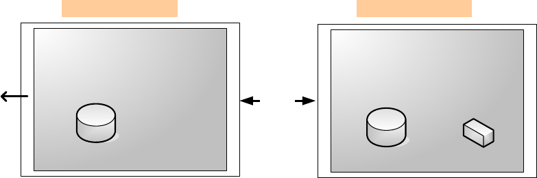
001-2019-500 Rev 0 Paragon4 – UHF, 700 & 800MHz User Manual
44
6.8.4.3 SNMP Overview
SNMP (Simple Network Management Protocol) is used by network management systems to manage and
monitor network-attached devices. SNMP is based on the manager/agent model consisting of a manager,
an agent, a database of management information, managed objects, and the network protocol. The manag-
er provides the interface between the human network manager and the management system. The agent
provides the interface between the manager and the physical devices being managed (Figure 35). SNMP
uses basic messages (such as GET, GET-NEXT, SET, and TRAP) to communicate between the manager
and the agent.
Figure 35 - SNMP: manager/agent model
6.8.4.3.1 MIB
The manager and agent use a Management Information Base (MIB), a logical, hierarchically organized
database of network management information. MIB comprises a complete collection of objects used to
manage entities in a network. A long numeric tag or object identifier (OID) is used to distinguish each
variable uniquely in the MIB and SNMP messages.
6.8.4.3.1.1 ParagonP4 MIB File
Each ParagonP4 unit firmware package is bundled with three MIB files (found inside mibs.zip file):
• dataradio-regs.mib: contains a top level set of managed object definitions aimed at managing Datara-
dio products.
• 1213.mib: contains a set of managed object definitions aimed at managing TCP/IP-based internets.
• bsc.mib: contains a set of managed object definitions aimed at managing Dataradio BSC radio base
stations.
6.8.4.3.1.2 OID
In SNMP, each object has a unique OID consisting of numbers separated by decimal points. These object
identifiers naturally form a tree. Figure 36 illustrates this tree-like structure for 1213.mib, which comes
bundled with every ParagonP4 unit package. A path to any object can be easily traced starting from the
root (top of the tree). For example, object titled “SNMP” has a unique OID: 1.3.6.1.2.1.11. The MIB as-
sociates each OID with a label (e.g. “SNMP”) and various other parameters. When an SNMP manager
wants to obtain information on an object, it will assemble a specific message (e.g. GET packet) that in-
cludes the OID of the object of interest. If the OID is found, a response packet is assembled and sent
back. If the OID is not found, a special error response is sent that identifies the unmanaged object.
MANAGER AGENT
Management Database Management Database Managed Object
Messages
Network
Protocol
Management System Managed Element
Human Network
Manager
Preliminary
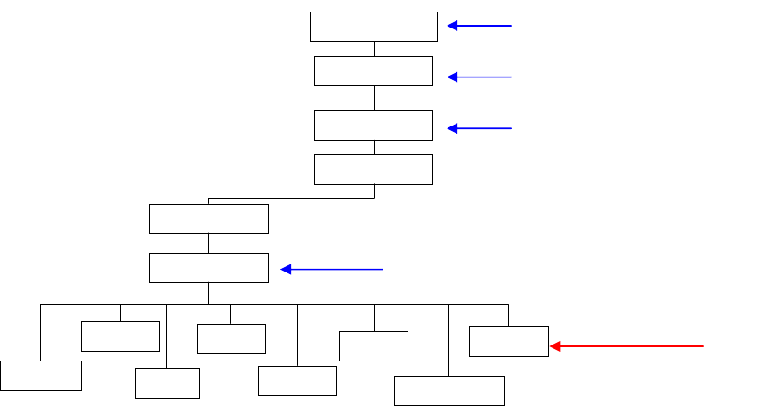
001-2019-500 Rev 0 Paragon4 – UHF, 700 & 800MHz User Manual
45
Figure 36 - Branch of the 1234.mib OID tree
6.8.4.3.1.3 Viewing MIB files
To view the hierarchy of SNMP MIB variables in the form of a tree and view additional information
about each node, Dataradio recommends opening all MIB files with a MIB browser. In a MIB browser,
each object (or node) can be selected and its properties (including its OID) can be observed.For simple
networks, any MIB browser supporting SNMP v2c could be used. However, for managing complex net-
works, a more advanced SNMP Manager/Browser is recommended.
Refer to Dataradio Network Management using SNMP User Manual (Part no. 120 47001-nnn for more
details).
Note: Both “Read Community” and “Read/Write Community” passwords are required to operate SNMP
MIB. For all Paragon base stations the same password is used for both read and read/write. This pass-
word is the same password used to access the Paragon4 web pages.
6.8.4.3.1.4 bsc.mib
Figure 37 shows top-level objects of the bsc.mib file:
• bscIdentity
• bscRadioIdentity
• bscStatistics
• bscDiagnostics
• bscControl
• bscMobileTable
These six branches expand into additional branches and leaves. Again, all bsc.mib objects can be accessed
through a MIB browser.
org (3)
iso(1)
ip(4)
icmp(5) SNMP (11)
udp(7)
system (1)
interfaces (2)
dod (6)
internet (1)
mgmt (2)
mib-2 (1)
tcp (6) transmission (10)
1.3.6.1.2.1
1.3.6.1.2.1.11
1
1.3.6
1.3
Preliminary
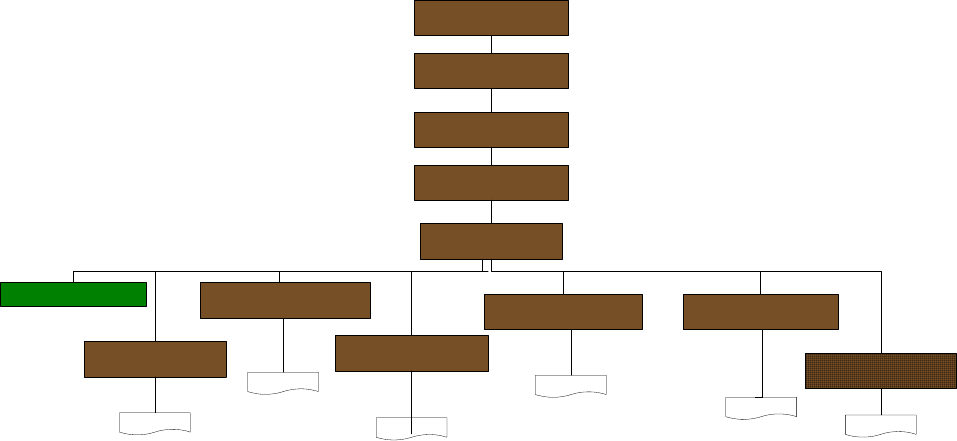
001-2019-500 Rev 0 Paragon4 – UHF, 700 & 800MHz User Manual
46
Figure 37 - bsc.mib Tree
Note: For more details on Network Management using SNMP refer to Dataradio Network Man-
agement using SNMP User Manual (Part no. 120 47001-nnn)
bscModule (1)
bscIdentity (2)
bscRadioIdentity (3) bscDiagnostics (5)
bscStatistics (4)
bscControl (6)
bscMobileTable (7)
bsc (3)
base (1)
...
...
...
... ...
...
1.3.6.1.4.1
dataradio (3732)
vis3network (5)
Preliminary
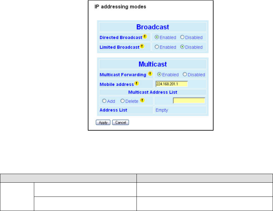
001-2019-500 Rev 0 Paragon4 – UHF, 700 & 800MHz User Manual
47
6.8.5 Setup (Advanced) ► IP addressing
For a description of the broadcast and multicast features of the Paragon4 radio modem, please refer to
paragraph 5.7.3.5.1 below.
Figure 38 - Advanced IP Configuration – IP addressing modes
The IP Addressing web page contains two sections, the one on top controls the forwarding of IP broadcast
packets and the other, on the bottom, controls IP multicast packets.
Each section acts independently.
Item Description
Broadcast
Directed Broadcast Disabled, Enabled (Default) – Controls forwarding of
Directed Broadcast packets
Limited Broadcast Disabled (Default), Enabled – Controls forwarding of
Limited broadcast packets
Preliminary

001-2019-500 Rev 0 Paragon4 – UHF, 700 & 800MHz User Manual
48
Multicast
Multicast
Disabled (Default), Enabled – Controls forwarding of
Multicast packets (based on the “Multicast Address
List”)
Multicast can be used when “one-to-many” communi-
cation is required.
Mobile unit address
This multicast address represents the "All Mobile"
group. When a Base station receives
an IP packet on its Ethernet interface and the destina-
tion IP address matches this multicast address,
the IP packet is forwarded over the RF interface to all
the Mobile units. The Mobile units will pass
this packet to their internal applications.
Multicast Address List
Add / Delete Address
The multicast address list is used to enter multicast
addresses for the various "Mobile Hosts" groups.
When a Base station receives an IP packet on its
Ethernet interface and the destination IP address
matches one of these address, the IP packet is for-
warded over the RF interface to all the Mobile units.
If multicast forwarding is enabled on the Mobile units,
the IP packet will be forwarded to the Mobile's Ethernet
interface, Mobile Hosts will then be able to receive the
packet.
The Mobile units have some additional filtering capa-
bilities.
To add an address to the Multicast List:
Select the “Add” option button and type in the dialog
box the new address to be added to the read-only
“Address List”. Note that only valid multicast ad-
dresses will be accepted and displayed.
To delete an address from the Multicast List: Select the
“Delete” option button and type in the dialog box the
address to be deleted from the “Address List”.
Address List
Read-only listing. Window expands downward as
needed to show all addresses in the list.
When an IP packet is received on the Ethernet side of
the unit and the destination IP address matches one of
the multicast IP addresses in this list, it is forwarded
over the RF interface.
Remote units will send it over their Ethernet interface.
Preliminary
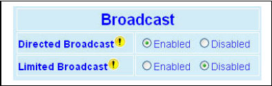
001-2019-500 Rev 0 Paragon4 – UHF, 700 & 800MHz User Manual
49
6.8.5.1 IP Broadcast/Multicast Overview
When an IP packet needs to reach more than one unit, the destination address can be set to either a broad-
cast address or a multicast address.
6.8.5.1.1 Broadcasts
Figure 39 - Broadcast Window Detail
There are two types of IP broadcast addresses:
• Directed broadcast
A directed broadcast address is an IP address where the host portion is all ones (for instance
172.30.1.255 is the directed broadcast address for the network 172.30.1.0/24, 172.30.1.207 is the
directed broadcast address for the network 172.30.1.192/28).
• Limited broadcast
The limited broadcast address is 255.255.255.255.
Note:
Routing equipment (to prevent broadcast storms) do not by default forward limited
broadcast packets (255.255.255.255). On the other hand, directed broadcast packets are
by default forwarded because these packets are routable like any other unicast packets.
6.8.5.1.1.1 Directed Broadcast
Each interface of a unit has its own IP address and netmask. From the IP address and netmask, it is easy
to calculate the broadcast address associated to the interface. For instance, if the Ethernet interface ad-
dress of a GeminiG3 radiomodem is 172.30.1.1/24 and the RF interface address is 10.0.1.2/24, then the
broadcast address of the Ethernet interface is 172.30.1.255 and the broadcast address of the RF interface
is 10.0.1.255.
The “Directed Broadcast” option buttons let the user select whether the unit must forward (or not) di-
rected broadcast packets. Upon reception of a directed broadcast packet, the unit takes the following ac-
tions:
If the directed broadcast address matches with one of the unit’s interface broadcast addresses:
• Keep a copy for itself (pass to internal applications, if any).
• If directed broadcast packets can be forwarded (Directed Broadcast is enabled):
Forwards the packet according to the routing table.
• If directed broadcast packets cannot be forwarded (Directed Broadcast is disabled):
Silently discards the packet.
Note:
Occasionally, the unit cannot determine that the packet is actually a directed broadcast. In such a
case, the packet is normally routed.
Preliminary
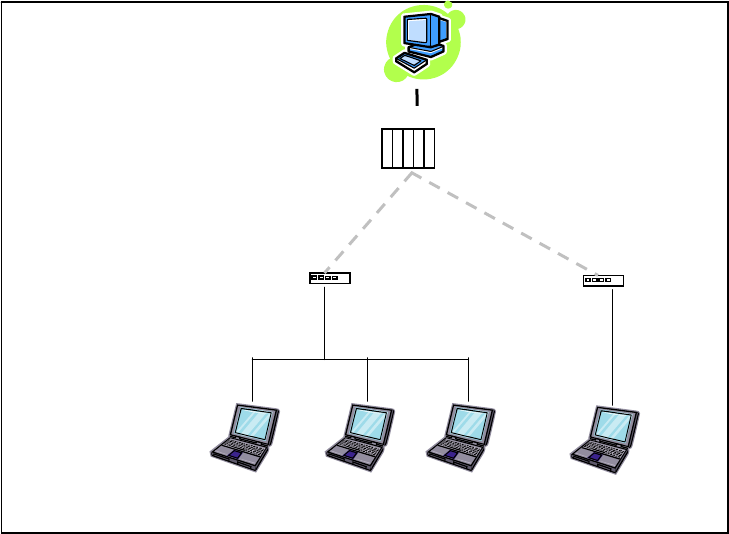
001-2019-500 Rev 0 Paragon4 – UHF, 700 & 800MHz User Manual
50
Example (Directed Broadcast forwarding enabled)
Figure 40 - Example of Directed broadcast forwarding enabled
In this example (Figure 40), directed broadcast forwarding is enabled on the Base unit and on Mobile (1)
unit. If Sender wants to reach Mobile Host (1), Mobile Host (2) and Mobile Host (3) with a single
packet, he can send to destination address 172.30.1.255.
Sender
Base (P4)
RF Airlinks
Mobile Host(2)
172.30.1.3/24
Mobile Host(3)
172.30.1.4/24
Mobile (1)
172.30.1.1/24 Mobile (2)
172.30.3.1/24
Mobile Host(1)
172.30.1.2/24
Mobile Host(4)
172.30.3.2/24
Directed broadcast forwarding
enabled
Directed broadcast forwarding
enabled
Send to 172.30.1.255
10.0.0.1/8
10.0.0.2/8 10.0.0.4/8
Preliminary
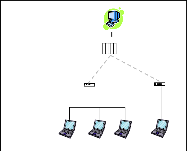
001-2019-500 Rev 0 Paragon4 – UHF, 700 & 800MHz User Manual
51
Example (Directed Broadcast forwarding disabled)
Figure 41 - Example of Directed broadcast forwarding disabled
In this example (Figure 41), directed broadcast forwarding is enabled on the Base unit and disabled on the
Mobile (1) unit. If Sender sends a packet to destination address 172.30.1.255, the packet would be dis-
carded by Mobile (1), it would not reach Mobile Host (1), Mobile Host (2) and Mobile Host (3).
If the user wants the Base unit to do the discarding of the directed broadcast packets, then the directed
broadcast forwarding must be disabled on the Base unit itself.
6.8.5.1.1.2 Limited Broadcast
The “Limited Broadcast” enabled/disabled option buttons control limited broadcast packets forwarding.
When enabled, the unit forwards limited broadcast packets.
Upon reception of a limited broadcast packet, the unit takes the following actions:
• Keeps a copy for itself (passes to internal applications, if any).
• If limited broadcast packets can be forwarded (Limited Broadcast is enabled):
Sends a copy of the packet out to all the interfaces with the exception of the interface where the pack-
et was received.
• If limited broadcast packets cannot be forwarded (Limited Broadcast is disabled):
Silently discards the packet.
Sender
Base (P4)
Mobile (1)
172.30.1.1/24
Mobile (2)
172.30.3.1/24
10.0.0.1/8
10.0.0.2/8 10.0.0.4/8
Directed broadcast forward-
ing enabled
Directed broadcast forward-
ing disabled
Send to 172.30.1.255
Mobile
Host(2)
Mobile
Host(3)
Mobile
Host(1)
Mobile
Host(4)
Preliminary
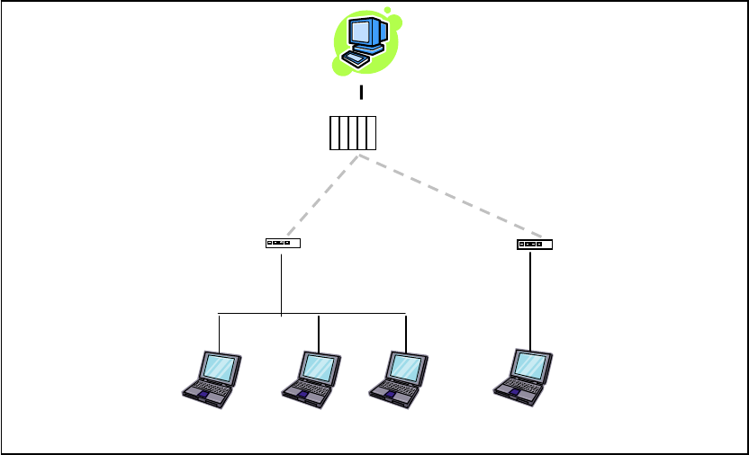
001-2019-500 Rev 0 Paragon4 – UHF, 700 & 800MHz User Manual
52
Example (Limited Broadcast forwarding enabled)
Figure 42 - Example of Directed broadcast forwarding enabled
In this example, (Figure 42) limited broadcast forwarding is enabled on the Base unit and on all Mobile
units. If Sender wants to reach Mobile Host (1), Mobile Host (2) and Mobile Host (3) and Mobile Host
(4) with a single packet, he can send to destination address 255.255.255.255.
Notice that Sender and Base units are on the same LAN (routing equipment does not usually forward
limited broadcast packets).
Base (P4)
RF Airlinks
Mobile Host
(2)
Mobile Host
(3)
Mobile (1)
172.30.1.1/24
Mobile (2)
172.30.3.1/24
Mobile Host
(1)
Mobile Host
(4)
10.0.0.1/8
10.0.0.4/8
Limited broadcast forwarding
enabled
Limited broadcast forwarding
enabled
Send to 255.255.255.255
Limited broadcast forwarding
enabled
Sender
10.0.0.2/8
Preliminary
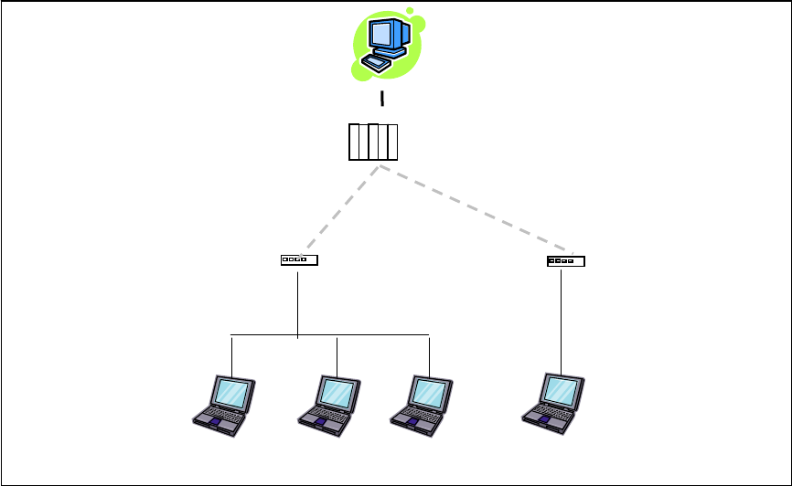
001-2019-500 Rev 0 Paragon4 – UHF, 700 & 800MHz User Manual
53
Example (Limited Broadcast forwarding disabled)
Figure 43 - Example of Limited broadcast forwarding disabled
In this example (Figure 43), limited broadcast forwarding is enabled on the Base unit, disabled on the
Mobile (1) unit and enabled on the Mobile (2) unit. If Sender sends a packet to destination address
255.255.255.255, the packet would reach Mobile Host (4) only. The Mobile (1) unit would discard any
limited broadcast packet it received from the Base unit.
If the user wants the Base unit to do the discarding of the limited broadcasting packets, then the limited
broadcast forwarding must be disabled on the Base unit itself. Then no Mobile Host unit would ever be
receiving a limited broadcast packet.
Base (P4)
RF Airlinks
Mobile Host (2)
172.30.1.3/24
Mobile Host (3)
172.30.1.4/24
Mobile (1)
172.30.1.1/24
Mobile (2)
172.30.3.1/24
Mobile Host (1)
172.30.1.2/24
Mobile Host (4)
172.30.3.2/24
10.0.0.1/8
10.0.0.4/8
Limited broadcast forwarding
enabled
Limited broadcast forwarding
disabled
Send to 255.255.255.255
Limited broadcast forwarding
enabled
Sender
10.0.0.2/8
Preliminary
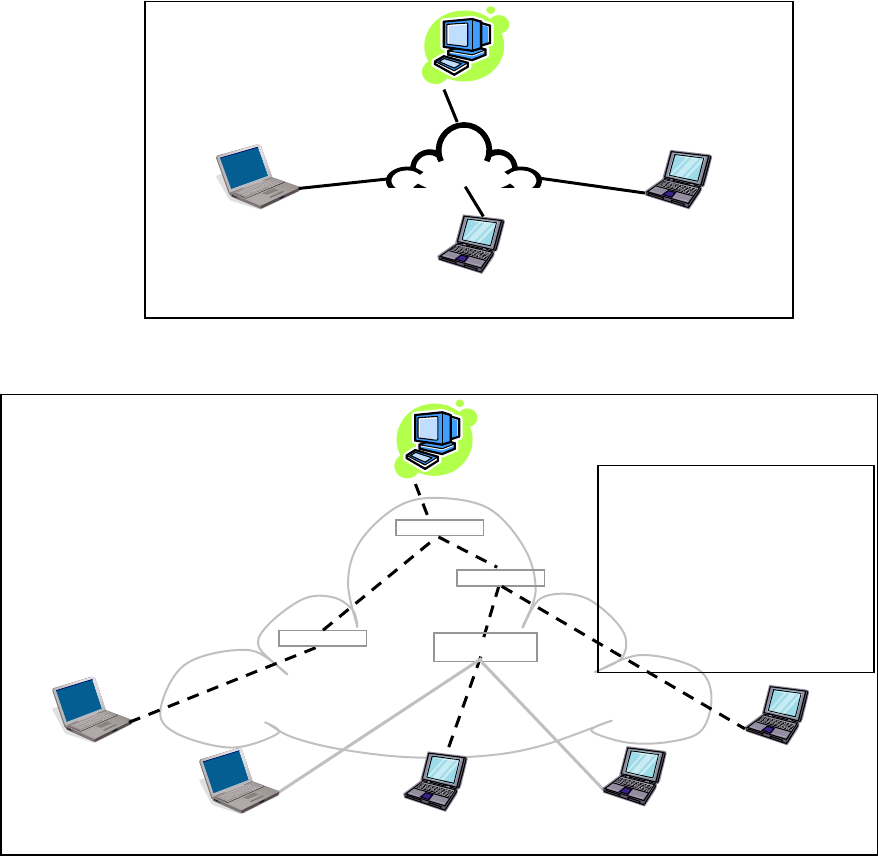
001-2019-500 Rev 0 Paragon4 – UHF, 700 & 800MHz User Manual
54
6.8.5.1.2 Multicast
IP multicast addresses are in the range 224.0.0.0 to 239.255.255.255. These addresses are used to
represent logical groups of units that may or may not reside on the same networks.
Multicast is used when “one-to-many” communication is required. For instance, a radio station might of-
fer a music channel on the Internet in real time. To receive the music a receiver-host must know the mul-
ticast group (multicast address) used by the radio station sender-host and add itself as a member of this
group. In the IP realm, a host uses the IGMP protocol to do this. The routers inside the Internet are using
IGMP and other multicast routing protocols to build the proper path from the sender to the receivers (a
tree-like path is formed from the sender to the receivers).
Figure 44 - Registration to multicast group (First step)
Figure 45 - Reception of multicast packets (Second step)
Sender (owner of multicast group 226.1.2.3)
Receiver 1
(member of 226.1.2.3)
Receiver 2
(member of 226.1.2.3)
Receiver 3
(member of 226.1.2.3)
Internet
IP Router
IP Router
IP Router
IP Router
Paths from Sender to Members
(Receivers 1, 2, and 3) flow in the
Internet from IP Router to IP Router
to reach
destinations 226.1.2.3.
Paths are not forwarded over inter-
faces that do not lead to a multicast
group member
5
1
2
2
3
3
4
Receiver
(not a member of 226.1.2.3)
Receiver
(not a member of 226.1.2.3)
Sender (owner of multicast group 226.1.2.3)
Receiver 1
(
Add membershi
p
226.1.2.3
)
Receiver 2
(
Add membershi
p
226.1.2.3
)
Receiver 3
(
Add membershi
p
226.1.2.3
)
Internet
Preliminary
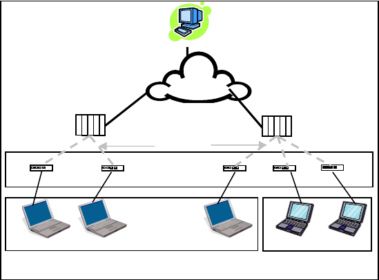
001-2019-500 Rev 0 Paragon4 – UHF, 700 & 800MHz User Manual
55
Sender
Network
“All Mobile”
Base
(
P4
)
Base
(
P4
)
RF A
i
r
-
Mobile Mobile Mobile Mobile Mobile
“Mobile Host” group 1 “Mobile Host”
g
rou
p
2
Mobile Mobile Mobile Mobile Mobile
In the E-DBA environment, an outside sender-host might be interested in sending multicast packets to
any one of the following groups:
• “All Mobile” group.
• Various “Mobile Host” groups.
The Base (P4 in the illustration) units are directly connected to the outside network. ALL multicast
groups MUST be identified in the Base because the Base unit uses IGMP to register the memberships to
the multicast groups on behalf of the other units (Mobile units, Mobile Host units).
Figure 46 - Typical E-DBA Multicast Groups
Preliminary
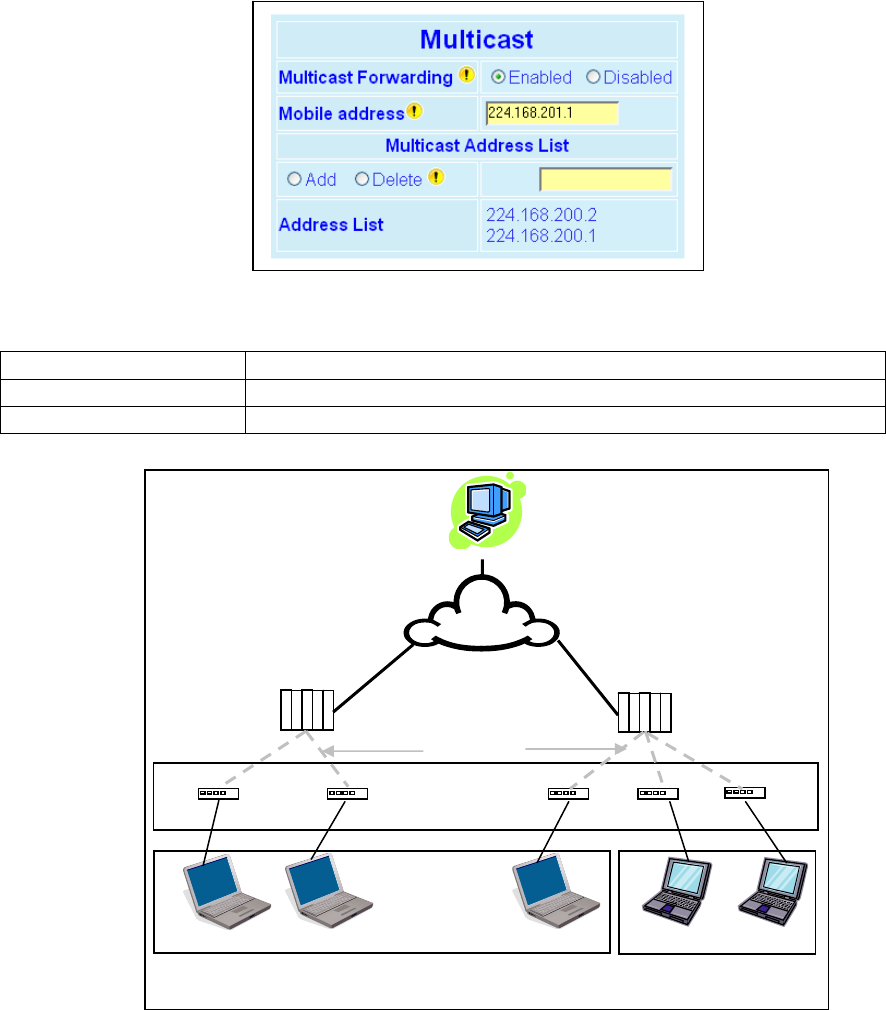
001-2019-500 Rev 0 Paragon4 – UHF, 700 & 800MHz User Manual
56
The following setup example would allow the “Sender” unit to communicate with different multicast
groups. The settings shown in Figure 47 below, and also represented in
Figure 48, would enable the Sender unit to reach all entities of the various groups.
Figure 47 - Multicast Window Details (On the Base station)
Multicast (Enabled/Disabled) Enables or disables the registration of the multicast groups by the Base
Mobile address Indicates the “All Mobile” multicast group
Multicast Address List Indicates the various “Mobile Host” groups
Figure 48 - Typical E-DBA Multicast Groups (with addresses)
Sender
Network
“All Mobile” group
(224.168.201.1)
Base (P4) Base (P4)
RF Airlinks
Mobile Host Mobile Host Mobile Host Mobile Host Mobile Host
“Mobile Host” group 1
(224.168.200.1)
“Mobile Host” group 2
(224.168.200.2)
Mobile (G3) Mobile (G3) Mobile (G3) Mobile (G3) Mobile (G3)
Preliminary
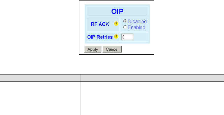
001-2019-500 Rev 0 Paragon4 – UHF, 700 & 800MHz User Manual
57
6.8.6 Setup (Advanced) ► IP Optimization
Figure 49 - Setup (Advanced)-Optimized IP Settings
Item Description
RF ACK
Disabled (Default) - TCP packets are always RF acknowledged regard-
less of this option setting.
Enabled - Use when packets need to be acknowledged at the RF level
by the remote unit (destination unit). This option is applicable to all
packet types other than TCP.
OIP Retries Number of OIP retries. Default = 2
Preliminary
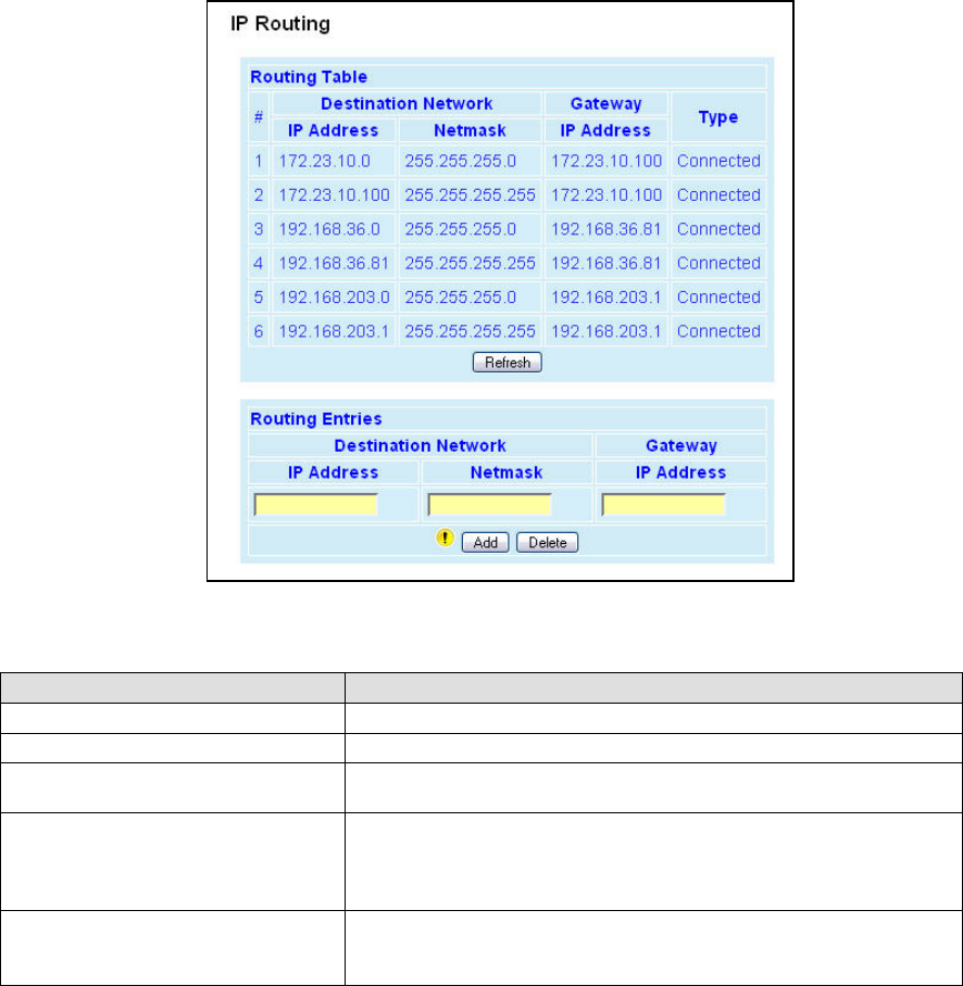
001-2019-500 Rev 0 Paragon4 – UHF, 700 & 800MHz User Manual
58
6.8.7 Setup (Advanced) ► IP Route
Displays the table of IP routes that are active in the Paragon4 base station.
Typically, display shows routes for RF, ETH1, and ETH2.
Figure 50 - IP Routing
Item Description
IP Address The address portion of the destination network
Netmask The mask portion of the destination network
Gateway IP Address: The IP address of the gateway to use when trying to reach
the given network
Type
Static: routes added by the user
Connected: addresses that are directly reachable by one of the inter-
faces
Proprietary: routes added internally by the Mobile registration process
Add / Delete
Allows the user to add or remove routes manually to/from the table.
Warning: Manipulate this table with caution!
Preliminary
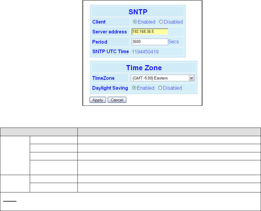
001-2019-500 Rev 0 Paragon4 – UHF, 700 & 800MHz User Manual
59
6.8.8 Setup (Advanced) ► Time Source
To facilitate tracking of events in a network, the Paragon4 base station and the GeminiG3 unit can initial-
ize their real-time clocks using a number of protocols. At reset time, the Paragon4 unit can use the SNTP
protocol (RFC2030) to pick up the current UTC (Universal) time. Setting the “TimeZone” and “Daylight
Savings” options allows displaying the correct local time in the “Unit Identification and Status” page.
Figure 51 - Advanced IP Configuration – Time Source
Item Description
SNTP
Client Disabled (Default), Enabled
Server address IP of the SNTP Server in dot decimal format
Period Period at which the SNTP Server is polled
SNTP UTC Time SNTP UTC Time
Last update received from the SNTP Server (in seconds) - Read-only field.
Time
Zone
TimeZone Select from drop-down list
Daylight Savings Disabled (Default), Enabled
Note: Due to transitional nature of Daylight Saving in many jurisdictions, we recommend that customers use UTC
for consistent, unambiguous time reporting, setting TimeZone to UTC and Daylight Saving to Disabled.
Preliminary
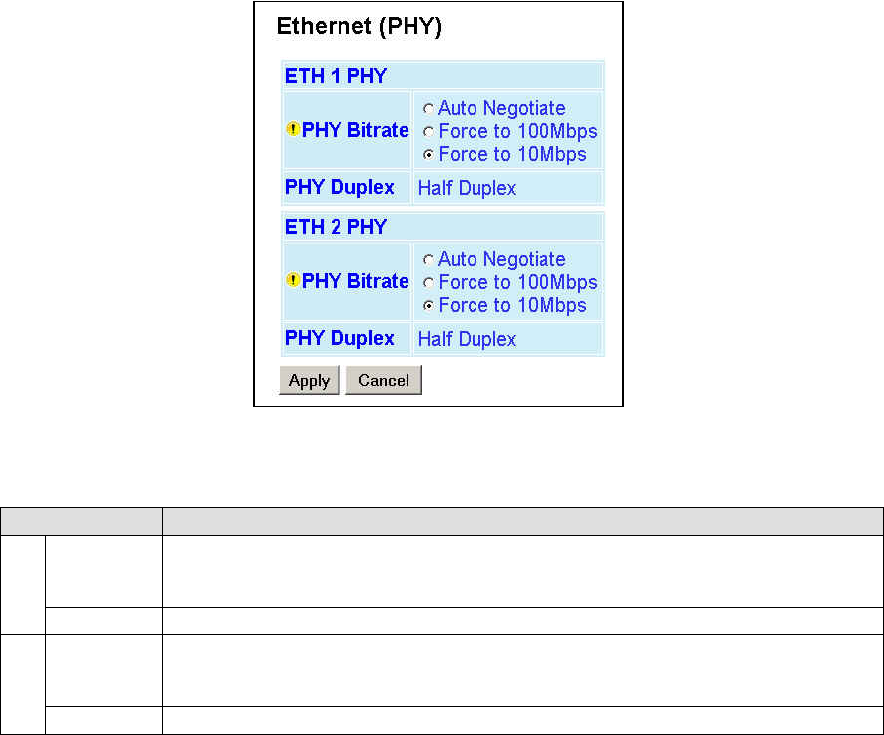
001-2019-500 Rev 0 Paragon4 – UHF, 700 & 800MHz User Manual
60
6.8.9 Setup (Advanced) ► Ethernet (PHY)
The Ethernet port(s) must be configured in a mode that is compatible with the other local devices.
Figure 52 - Advanced IP Configuration – Ethernet (PHY)
Item Description
ETH1
PHY
PHY Bitrate
Auto Negotiate
Force to 100 Mbps
Force to 10 Mbps (Default)
PHY Duplex Displays factory configured mode of operation: Auto Negotiate
ETH2
PHY
PHY Bitrate
Auto Negotiate
Force to 100 Mbps
Force to 10 Mbps (Default)
PHY Duplex Displays factory configured mode of operation: Half Duplex
Preliminary
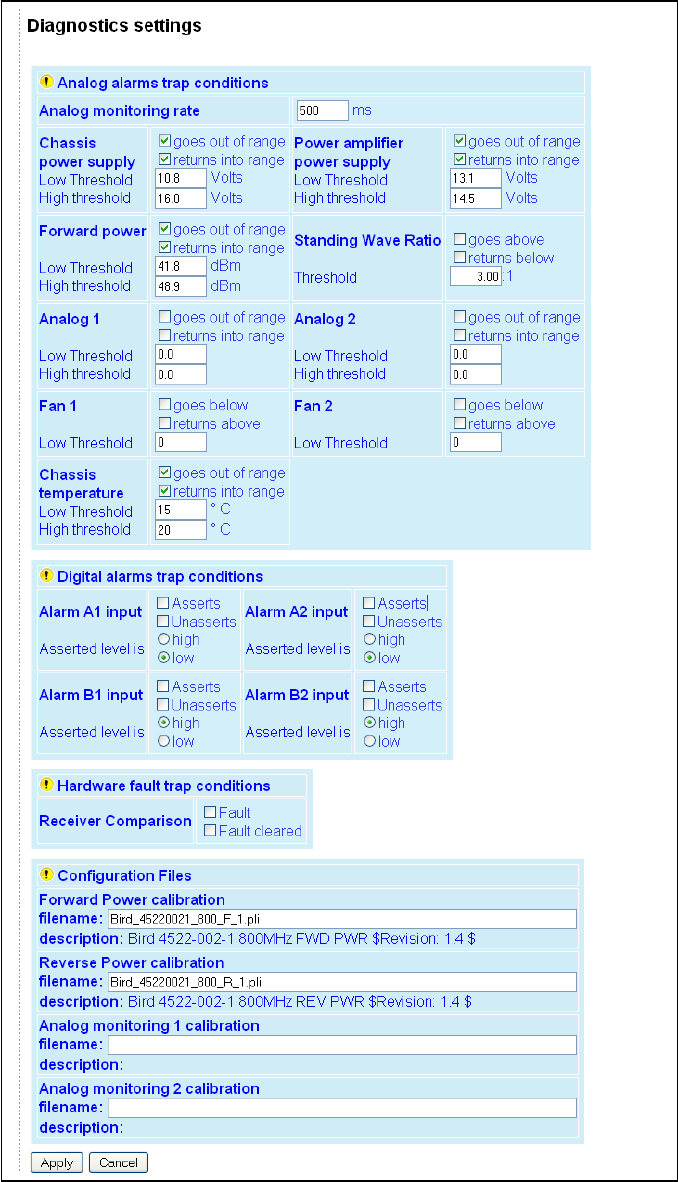
001-2019-500 Rev 0 Paragon4 – UHF, 700 & 800MHz User Manual
61
6.8.10 Setup (Advanced) ►Diagnostic Settings
Figure 53 - Advanced IP Configuration – Diagnostic Settings
Preliminary

001-2019-500 Rev 0 Paragon4 – UHF, 700 & 800MHz User Manual
62
Item Description
Analog alarms trap conditions
Analog Monitoring Rate Frequency at which internal values are updated and checked against the alarm
boundary conditions. Ranges from 100milliseconds to infinity. Default = 500ms
Analog alarms settings
For each diagnostic value displayed, the user can control alarms trap conditions
in the following ways:
Set acceptable range of values by entering the low and high thre-
sholds
Choose to be notified when the value goes out of acceptable range by
selecting the “goes out of range” check box
Choose to be notified when the value returns into acceptable range by
selecting the “returns into range” check box
All monitoring combinations are possible
Digital Alarms trap conditions
Digital Alarms settings
For all digital alarms, the traps can be sent when:
“Asserted:-The digital signal changes from low to high
“Unasserted”-The digital signal changes from high to low
All monitoring combinations are possible
Hardware fault trap conditions
Receiver Comparison
To diagnose a possible receiver malfunction
Choose to be notified when a Receiver Comparison fault occurs by se-
lecting the "Fault" check box.
Choose to be notified when a Receiver Comparison fault has been cor-
rected by selecting the "Fault cleared" check box.
Calibration Files
Calibration Files
All Paragon4 unit firmware comes bundled with two interpolation files used for
forward and reverse power calibration. These files are required to be used with
the optional external power sensor assembly (p/n 030 03547-xxx).
Caution: Forward & reverse power readings will not be accurate without the
optional external power sensor assembly (p/n 030 03547-xxx).
Refer to your Dataradio sales channel for details.
The file names entered in this section should match the file names in your unit
(Note: file names are case sensitive.) These files are needed to properly display
the Forward and Reverse power values.
6.8.10.1 Calibration Files
Special electrical sensors are used to measure the values of real world quantities such as forward or re-
verse RF power. These sensors represent all measurements in Volts and require a conversion to proper
units where applicable. This conversion is achieved by use of mathematical transfer functions, which also
provide a way of calibrating the sensor hardware.
The transfer function can be represented by a simple look-up table that approximates a continuous func-
tion by a series of data points. Each data point represents an {Xin, Yout} pair, where Xin is the sensor’s
output-a measurement in Volts, and Yout is the corresponding value in a desired unit of measurement. Li-
near interpolation is used to generate Yout values for any given Xin value in between the data points sup-
plied in the look-up table.
The series of data points in a look-up table are listed in a text calibration file and is read by the Piecewise
Linear Interpolation Calibrated Conversion (PWLICC) software module, employed in Paragon4 radio
base station to convert the sensor output into a desired value.
Dataradio supplies look-up tables for forward and reverse power measurements. These tables contain a set
of values in Volts (Xin) with their corresponding values in Watts (Yout). Similar look-up tables need be
created for user-supplied external analog devices connected to the base station’s backplane for diagnostics
and monitoring if other than voltage measurement units are preferred.
Preliminary
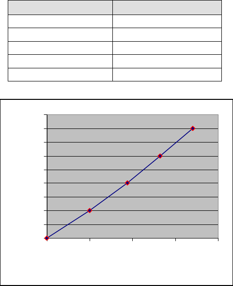
001-2019-500 Rev 0 Paragon4 – UHF, 700 & 800MHz User Manual
63
An example of a look-up table is presented in Table 5 with a corresponding graph in Figure 54
Table 5 - Sample Interpolation endpoints
Figure 54 - Sample Interpolation curve
Values in-between the data points are calculated using a straight line between the closest two known data
points. At least 2 data points are required; however 10 or 20 data points (up to 50) are usually necessary
(depending on the curves behavior).
A look-up table can be created with a simple text editor, such as MS-Notepad, carefully following the
guidelines presented below. The basic syntax is summarized in Table 5.
• // symbol preceding any entry denotes comments.
• [c] symbol preceding a string of up to 80 characters denotes file description. This string will be dis-
played under “description” field on the “Diagnostics Settings” page of the Pargon3 web interface.
• [u] symbol preceding a string of up to 15 characters denotes the desired unit of measure.
• [n] symbol preceding an integer denotes the number of entries in the look-up table.
• Data points are filled in as {Xin, Yout} pairs. Each pair occupies a line and counts one space in be-
tween its elements:
Xin1Yout1
Xin2 Yout2
Xin3 Yout3
……..
• The number of {Xin, Yout} pairs must correspond to the index ([n]) entered.
• Empty lines are not accepted-use comments for formatting.
• Duplicate Xin values are not accepted.
Xin (Volts) Yout (Desired Units)
0.0 0.0
0.2 1.0
0.375 2.0
0.530 3.0
0.530 4.0
0
0.5
1
1.5
2
2.5
3
3.5
4
4.5
0 0.2 0.4 0.6 0.8
Xin (Volts)
Yout (Desired Units)
Preliminary
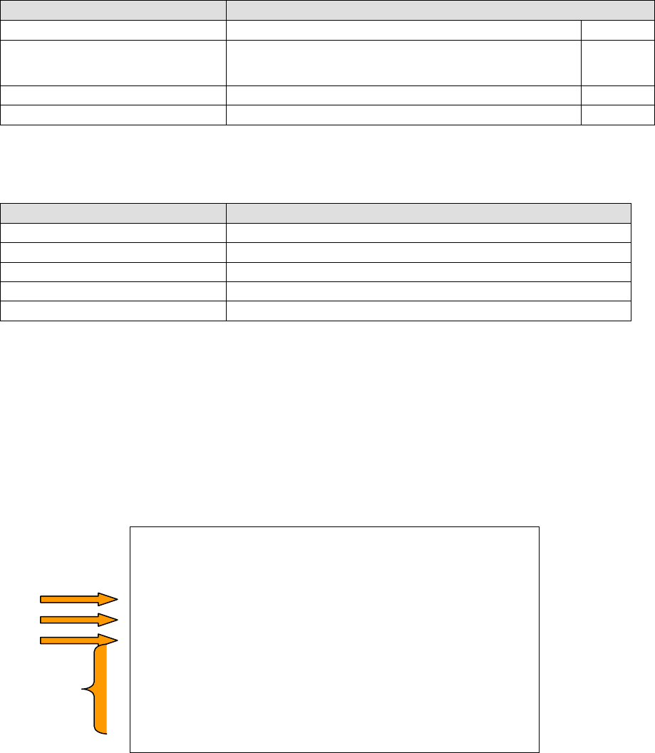
001-2019-500 Rev 0 Paragon4 – UHF, 700 & 800MHz User Manual
64
• When complete, use the “Save As” command.
• The file name is case-sensitive and spaces are not allowed.
• The file name should be saved under .pli extension.
• The file should be uploaded into a unit using FTP transfers.
• The file’s name should be entered under “Analog monitoring 1 calibration” (and/or “Analog monitor-
ing 2 calibration”) field on the Diagnostic page of the Paragon4 web interface.
Table 6 - PLICC Syntax
Syntax Description
// <comment> Comments. Optional
[c] <name>
Descriptive name of the look-up table (string of 80 characters
max). This field will appear under the “description” field on
the Diagnostics Settings” page of the Pargon3 web interface.
Optional
[u] <unit> Unit of measure (string of 16 char maximum). Optional
[n] <index> Number of entries in the table (2 minimum, 50 maximum). Required
Failure to comply with the guidelines described above may result in the following errors:
Table 7 - Possible Error messages
Error Description
No file found The file name entered is not found on the unit.
Bad header or bad file format found. Syntax Error .
No data found. No data entered in the file (less than 2 data points).
More than 50 segments found in file. The file counts more than 50 data points.
Duplicate X values found in data. The file contains duplicate Xin values.
A sample calibration file is presented in Figure 55. Please note the following:
1. “Volts to watts conversion” will appear under the “description” field on the “Diagnostics Settings”
page of the Pargon3 web interface.
2. This look-up table contains a set of values in Volts with their corresponding values in Watts.
3. This look-up table contains five data points.
4. The number of data points should correspond to the index (entered under [n]). All Xin entries (voltage
values) must be unique.
// file name: sample_calibration_file.pli
// Revision: N.NN
// Date: YYYY/MM/DD
// Other Comments
[c]Volts to watts conversion
[u]Watts
[n]5
0.000 0.0
0.200 1.0
0.375 2.0
0.530 3.0
0.530 4.0
Figure 55 - Sample calibration file
2
3
1
4
Preliminary
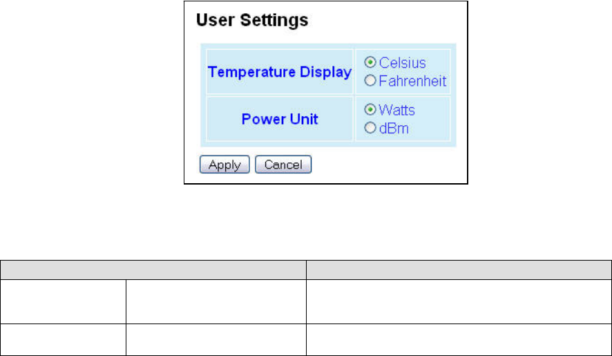
001-2019-500 Rev 0 Paragon4 – UHF, 700 & 800MHz User Manual
65
6.8.11 Setup (Advanced) ►User Settings
Figure 56 - Advanced IP Configuration - User Settings
Item Description
Temperature Display Celsius (default)/Fahrenheit
Select desired temperature scale. Where applicable,
the temperature will be displayed in selected tempera-
ture scale.
Power Unit Watts (default)/ dBm Select desired power scale. Where applicable, the
power will be displayed in selected power scale.
Preliminary
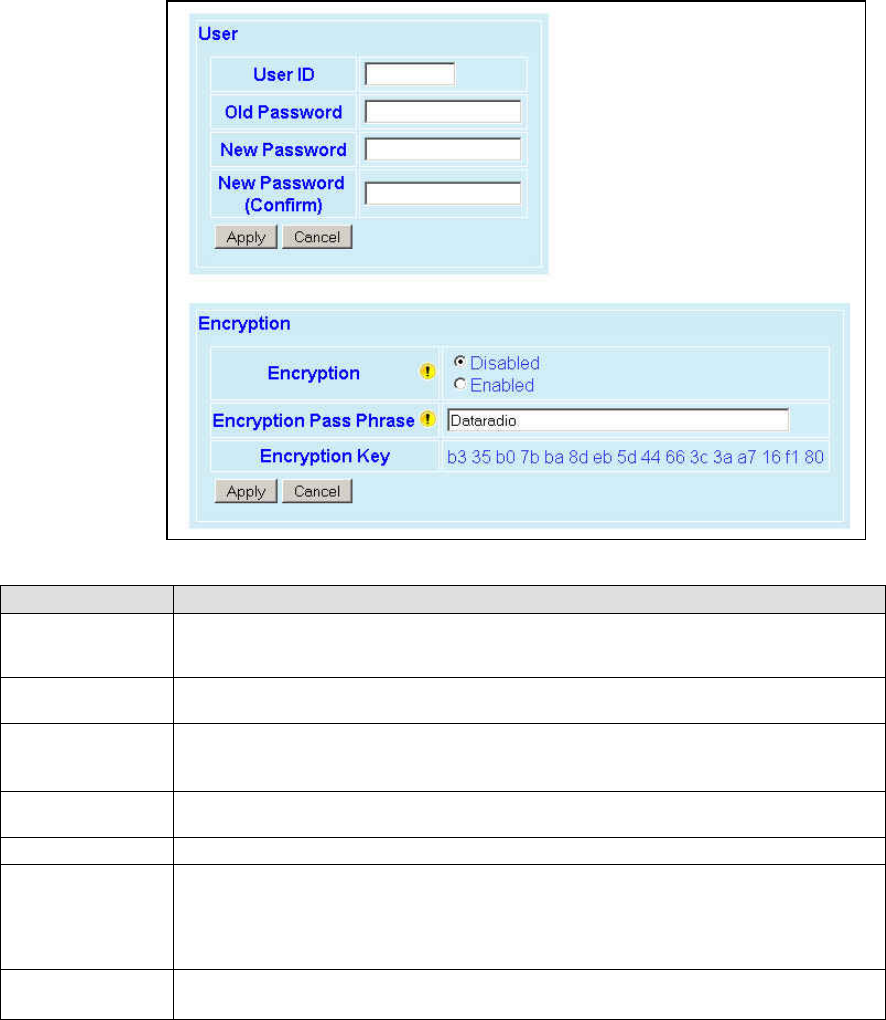
001-2019-500 Rev 0 Paragon4 – UHF, 700 & 800MHz User Manual
66
6.9 Security
6.9.1 Security ► Password and Encryption Control
The Setup web pages, the CLI (command line interface) and the FTP server all require a password to pre-
vent unauthorized users from changing a unit’s configuration. At the time of manufacture, the password is
set to “ADMINISTRATOR” but Dataradio strongly suggests that the password be changed as units are
installed.
Figure 57 - Security – Password and Encryption
Item Description
User ID
Enter a string of any letters or numbers of at least 1 and not exceeding 15 characters
The User Name entry is currently not an access-limiting factor. It only serves to identify
the person gaining access. User Name may be required by future versions.
Old Password For an initial installation, enter the default Password ADMINISTRATOR (all upper case
letters). For subsequent access, use the Password that you will have configured.
New Password
Enter a string of any letters or numbers of at least 8 and not exceeding 15 characters
CAUTION: Do not lose the new password or you will not be able to gain access to the unit;
you will need to contact CalAmp support.
New Password
(confirm) Re-enter the new password string
Encryption Disabled, Enabled (Default)
Encryption Pass
Phrase
String of characters used to create a 128-bit AES encryption key. The Pass Phrase can be
up to 160 characters long. Using a length of at least 128 characters should provide an
adequate security level for most users.
A good pass phrase mixes alphabetic and numeric characters, and avoids simple prose
and simple names.
Encryption Key All units in a network must have the same key.
READ ONLY - Displayed in pairs separated with spaces
Preliminary
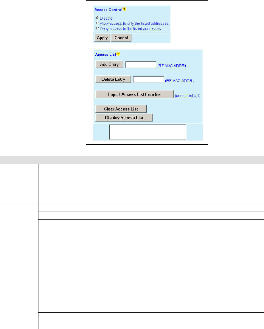
001-2019-500 Rev 0 Paragon4 – UHF, 700 & 800MHz User Manual
67
6.9.2 Security ► Access Control
Figure 58 - Security - Access List
Item Description
Access List
Control Access List Control
Access List is used to keep unauthorized unit(s) away from Dataradio RF
network. Maximum number of Access List entries = 100.
The Access List Control takes the following values:
Disabled (Default)
Allow or Deny – Authorized units only. Requests from any unit(s) outside
this list will be rejected.
Access List
Management
Add Entry Adds entry in the Access Control List
Delete Entry Deletes entry in the Access Control List
Import Access list
from file
Imports Access List from file – Populates Access Control table from the
file “accesslist.acl“. It is basically a text file that contains a list of
RF MAC addresses.
E.g.:
0x1234
abcd
2345
where, 0x1234, abcd, and 2345 represent RF MAC addresses in HEX
To use this feature:
-Create a text file “accesslist.acl” with a list of RF MAC addresses
-Upload the file from a host PC via an FTP program
-Click on “Import Access list from file” button
-Click on “Display Access List” button to view the imported access list
Clear Access List Clears entire Access Control table
Display Access List Clicking this button opens the access list in the message window
Preliminary
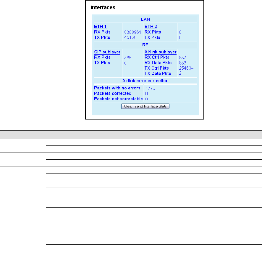
001-2019-500 Rev 0 Paragon4 – UHF, 700 & 800MHz User Manual
68
6.10 Statistics
Statistics web pages allow the user to view data transmission statistics (Interfaces) and base station per-
formance (Channel Utilization).
6.10.1 Statistics ► Interfaces
Figure 59 - Statistics – Interfaces
Item Description
LAN(ETH1) RX Pkts Total number of packets received by Ethernet 1 interface
TX Pkts Total number of packets transmitted by Ethernet 1 interface
LAN(ETH2) RX Pkts Total number of packets received by Ethernet 2 interface
TX Pkts Total number of packets transmitted by Ethernet 2 interface
RF
RX Pkts (RF-OIP) Total number of packets received by RF-OIP interface
TX Pkts (RF-OIP) Total number of packets transmitted by RF-OIP interface
RX Ctrl Pkts (RF-Airlink) Total number of control packets received by RF-Airlink interface
RX Data Pkts (RF-Airlink) Total number of data packets received by RF- Airlink interface
TX Ctrl Pkts (RF-Airlink) Total number of control packets transmitted by RF- Airlink inter-
face
TX Data Pkts (RF-Airlink) Total number of data packets transmitted by RF- Airlink inter-
face
Airlink error
correction
Packets with no error Number of E-DBA packets, control or data, received over-the-air
with zero error.
Packets corrected Number of E-DBA packets, control or data, received over-the-air
with correctable errors.
Packets not correctable Number of E-DBA packets received over-the-air with errors that
could not be corrected. These packets were discarded.
Preliminary
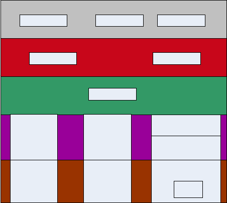
001-2019-500 Rev 0 Paragon4 – UHF, 700 & 800MHz User Manual
69
6.10.1.1 Interface Statistics Conventions
To reduce their design complexity, most networks are organized as a series of layers or levels, each one
built upon its predecessor. Layer n on one machine carries on a conversation with layer n on another ma-
chine. The rules and conventions used in this conversation are collectively known as the layer n protocol.
The number of layers, the name of each layer, the contents of each layer, and the function of each layer
differ from network to network.
Figure 60 below illustrates layers and protocols applicable to Dataradio network architecture implementa-
tion. The five basic layers are:
• Physical Layer
• Datalink Layer
• Network Layer
• Transport Layer
• Application Layer
Figure 60 - Layers and protocols applicable to Dataradio implementation
In reality, no data are directly transferred from layer n on one machine to layer n on another machine. In-
stead, each layer passes data and control information to the layer immediately below it, until the lowest
layer is reached (Figure 61).
Paragon4 radio base station web interface presents data transmission statistics for the Datalink layer.
Network and Transport layers statistics are not accessible through the web interface; they are provided in
1213 MIB and can be accessed through a MIB browser or an SNMP manager (see section 6.8.4.3: SNMP
Overview for more details on 1213 MIB).
TRANSPORT LAYE
R
NETWORK LAYER
DATALINK LAYER
PHYSICAL LAYER
TCP UDP
IP
ETH2ETH1
RF-OIP
ETH PHY ETH PHY
EDBA PHY
FEC
RF-
A
IRLINK
HTTP SNMP FTP
APPLICATION LAYE
R
Preliminary
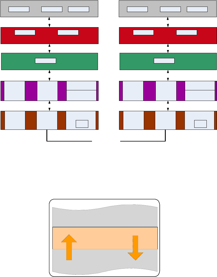
001-2019-500 Rev 0 Paragon4 – UHF, 700 & 800MHz User Manual
70
Figure 61 - Layer, protocols, and interfaces applicable to Dataradio implementation
All statistics presented by Dataradio follow a convention presented in Figure 62. Layer n statistics are
given with respect to the layer immediately below it: layer n-1. RX (Receive) or IN refers to data received
by layer n from layer n-1. Transmit (TX) or OUT refers to data transmitted by layer n to layer n-1.
Figure 62 - RX and TX Convention
6.10.1.1.1 Datalink Layer Statistics
Datalink layer comprises two Ethernet interfaces (ETH1 and ETH2) and an RF interface. Ethernet1 and
Ethernet2 interfaces statistics are illustrated in Figure 63.
Layer N
Layer N+1
Layer N-1
RX/IN
TX/OUT
Convention
TRANSPORT LAYER
NETWORK LAYER
DATALINK LAYER
PHYSICAL LAYER
HTTP SNMP FTP APPLICATION LAYER
HOST
A
TCP UDP
IP
TRANSPORT LAYER
NETWORK LAYER
DATALINK LAYER
PHYSICAL LAYER
ETH2ETH1
RF-
A
IRLIN
K
RF-OIP
Layer P
/
D Interface
Layer D
/
N Interface
Layer N
/
T Interface
ETH PHY ETH PHY
EDBA PH
Y
FEC
Layer T
/
A Interface
APPLICATION LAYER HTTP SNMP FTP
HOST B
TCP UDP
IP
ETH2ETH1
RF-
A
IRLIN
K
RF-OIP
Layer P
/
D Interface
Layer D
/
N Interface
Layer N
/
T Interface
ETH PHY ETH PHY
EDBA PH
Y
FEC
Layer T
/
A Interface
TRANSPORT MEDIA
Preliminary
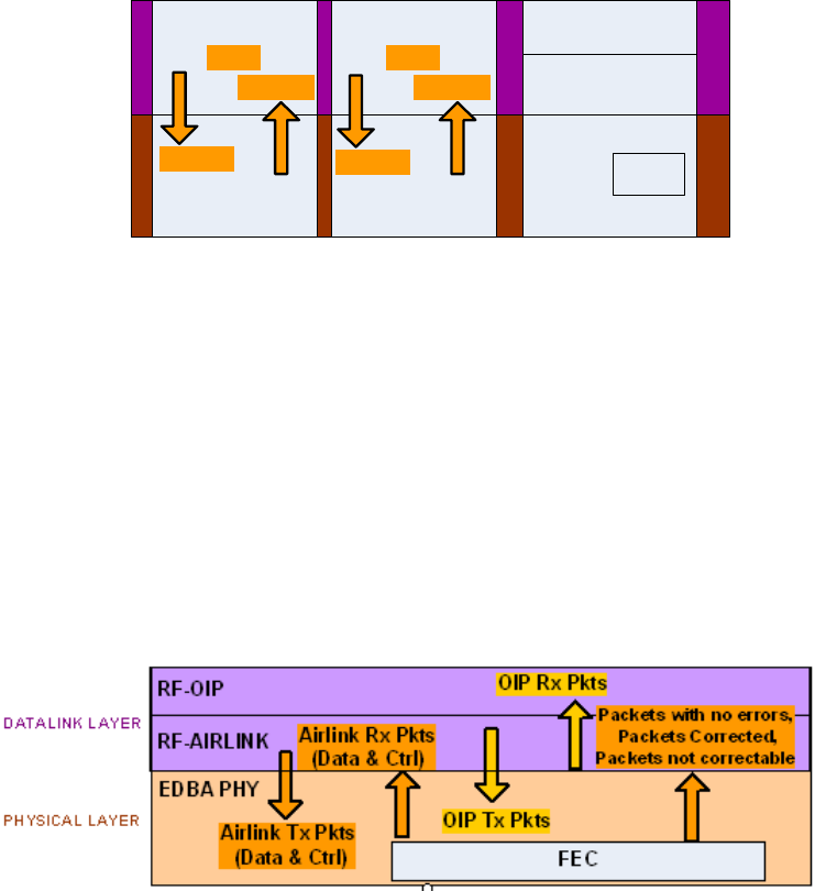
001-2019-500 Rev 0 Paragon4 – UHF, 700 & 800MHz User Manual
71
Figure 63 - Datalink Ethernet Statistics
RF interface is further subdivided into two sub-layers: OIP sub-layer and Airlink sub-layer. OIP (Opti-
mized IP) sub-layer is concerned with compression, optimization, TCP proxy control, and IP roaming.
Airlink sub-layer is where Dataradio’s Enhanced Dynamic Bandwidth Allocation (E-DBA) Airlink proto-
col resides.
RF interface statistics are illustrated in Figure 64. Each E-DBA cycle consists of a fixed number of con-
trol packets (e.g.: Requests, Acknowledgements, etc...) and a dynamically allocated number of data pack-
ets. This is why both Data and Control packets count appear at the Air link sub-layer.
RF interface statistics also include error correction statistics for all incoming packets. The corrections are
accomplished with a forward error correction (FEC) module. The advantage of forward error correction is
that retransmission of data can often be avoided.
Figure 64 - Datalink RF Statistics
DATALINK LAYER
PHYSICAL LAYER
ETH1
RF-AIRLINK
RF-OIP
ETH PHY
EDBA PHY
FEC
Tx Pkts
Rx Pkts
ETH2
ETH PHY
Tx Pkts
Rx Pkts
Preliminary
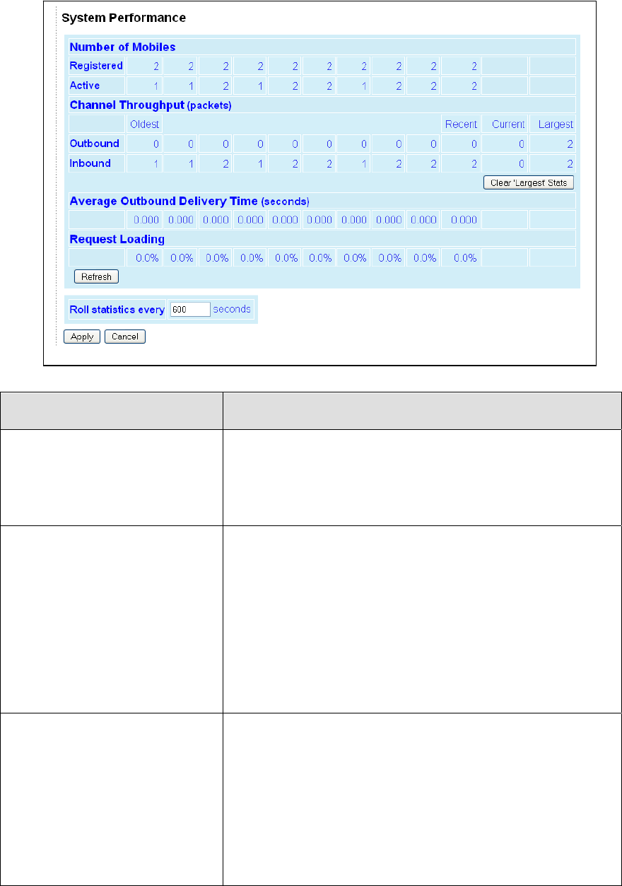
001-2019-500 Rev 0 Paragon4 – UHF, 700 & 800MHz User Manual
72
6.10.2 Statistics ► Performance
Figure 65 - Statistics - System Performance
Item Description
Number of Mobiles
Registered: Records the maximum number of mobiles registered at
any time over the statistics period
Active: Records the number of mobiles that have actively transmitted
or received data during the statistics period. This value can be larger
than the number of Registered mobiles for a period if enough mobiles
have registered and then roamed away from the base during the statis-
tic period.
Channel Throughput
Outbound: Records the number of data packets sent outbound during
the statistics period. The number of packets sent so far during the
Current period is shown, as is the Largest value recorded for any pe-
riod.
Inbound: Records the number of data packets scheduled for inbound
during the statistics period. The number of packets scheduled so far
during the Current period is shown, as is the Largest value recorded
for any period. (The number of packets scheduled may not match the
number of packets actually received. See Statistics → Interfaces page
for counts of the number of packets received.
The Clear 'Largest' Stats button clears the two values in the Largest
column. The Largest values can be used to compare the current set of
statistics with the busiest outbound & inbound periods.
Average Outbound Delivery Time
Records the average time from which an outbound IP message is pre-
sented to the airlink until the RF acknowledgement for that message is
received. Broadcast/Multicast messages that are not acknowledged do
not contribute to the statistic, nor are outbound messages that retry
and fail to reach their destination mobile.
An increasing Average Outbound Delivery Time is usually an indica-
tion of increasing traffic on the RF channel but Delivery Time can also
be affected by an increase in the number of retries needed to reach
distant mobiles.
Note: The Average Delivery time for each registered mobile is also
available on the Remote Table page.
Preliminary

001-2019-500 Rev 0 Paragon4 – UHF, 700 & 800MHz User Manual
73
Request Loading
Records the percentage of occupied Request slots compared to the
number of slots made available by the base during the statistics pe-
riod. A loading of 40% or more would indicate a very busy channel.
A network whose mobiles send data inbound in very short bursts (eg.
license plate inquiries) may see a busy channel due to request loading
even though the inbound channel throughput value is comparatively
low.
Roll statistics every ... seconds
Sets the statistics period to the specified number of seconds. The
change takes effect immediately and the existing history is not cleared
so the history may appear inconsistent until values recorded using the
old period have rolled off the table.
Refresh
This button refreshes the displayed statistics.
Preliminary
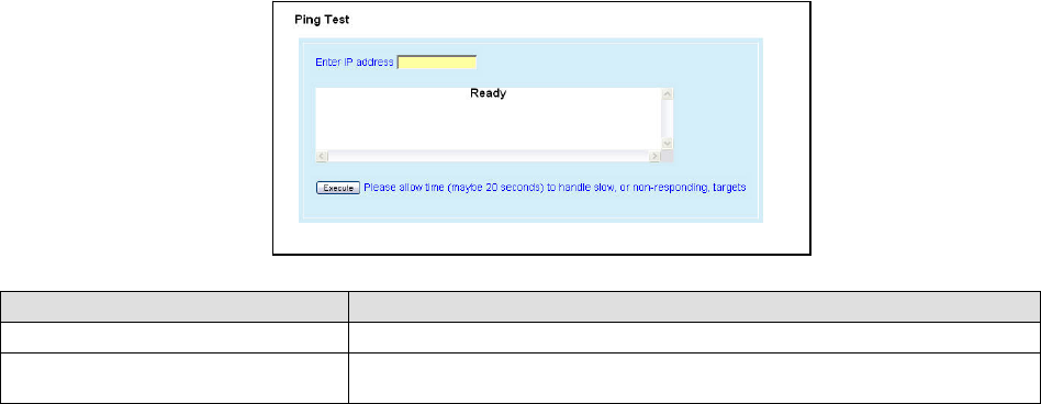
001-2019-500 Rev 0 Paragon4 – UHF, 700 & 800MHz User Manual
74
6.11 Maintenance
6.11.1 Maintenance ► Ping Test
To aid in trouble-shooting IP connectivity issues, the Paragon4 base stations and the GeminiG3 mo-
biles can transmit ping packets to a given IP address. Four packets are sent and the time taken for
each to reach the destination and return is displayed.
Figure 66 - Maintenance – Ping Test
Item Description
Enter IP address Enter IP address to ping, in dot decimal format
Execute This button executes the ping command. Ready field displays the outcome of
the ping command.
Preliminary
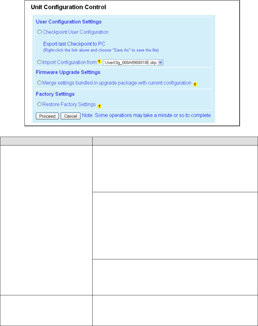
001-2019-500 Rev 0 Paragon4 – UHF, 700 & 800MHz User Manual
75
6.11.2 Maintenance ► Config Control
Figure 67 - Maintenance -Configuration Control (Initial screen)
Item Description
User Configuration Settings
Checkpoint User Configuration -saves a set of the current user configu-
ration settings in the Paragon4 base station.
Click on the Checkpoint User Configuration radio button. Click Pro-
ceed to save the settings to the configuration file. The new configura-
tion file's name will consist of UserCfg_ and the Paragon4's ETH1 MAC
address. (Example: UserCfg_000A99012345.drp). If a previous check-
point had been saved to the UserCfg_macaddress.drp file then the new
checkpoint will overwrite the existing file.
Click “Export last Checkpoint to PC” link to save the configuration file
to a PC. A save dialog box will appear. Select the file name and folder to
save the configuration file to and click save.
The configuration file may be renamed, if desired, (must keep the .drp
extension) then reloaded back into the original Paragon4 or into anoth-
er Paragon4 by using an FTP client. Do not load more than 5 separate
configuration files into a single Paragon4. Loading many configuration
files into a Paragon4 may use up an excessive amount of memory and
may cause the Paragon4 to malfunction. After saving the configuration
file back into the Paragon4 with an FTP Client, select Import Configura-
tion from and follow the instructions below.
Import Configuration from
To restore a user configuration, click the Import Configuration from
radio button. The drop down combo box will show all the .drp files
(configuration files) in the Paragon4. Select the configuration file to
load and click on Proceed. Click Save Config then Reset Unit to com-
plete the process and store these settings to the unit.
Firmware Upgrade Settings
Merge settings bundled in upgrade package with current configuration-
merges upgraded settings with the current configuration.
Note: the "firmware update" process will end up replacing an existing
configuration file with the one that came bundled with the firmware
upgrade package.
Preliminary
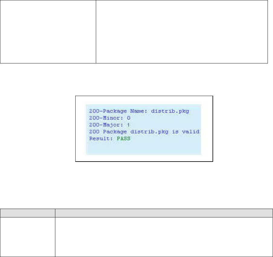
001-2019-500 Rev 0 Paragon4 – UHF, 700 & 800MHz User Manual
76
Factory Settings
Restore Factory Settings: restores all settings do default factory confi-
guration.
Upon performing the firmware upgrade, should you decide to restore to
factory settings instead of to “merge with bundled settings”, simply
select the “Restore Factory Settings” option button right after perform-
ing the firmware upgrade and click on “Proceed”.
Important note:
Activating “Restore Factory Settings” will reset the IP address of the
unit. Have your record of all the original Paragon 3 factory settings
handy before proceeding with restoring to factory settings.
6.11.3 Maintenance ► Package Control
Figure 68 - Maintenance – Package Control
Item Description
Package Control
Used for verifying the field upgrade of the Paragon4 radio modem firmware.
The firmware transfer procedure outlined in section 7.5.1 instructs to “Click on Maintenance
/ Package Control to verify integrity and wait a few moments for the results to display”.
Figure 68 above shows a “Pass” result indication.
If an upgrade problem arises and persists, click the “Package Control” once more and have
the resulting indications handy if contacting Dataradio System Engineering.
Preliminary
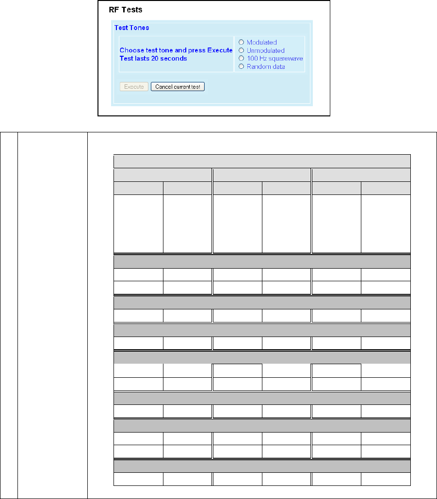
001-2019-500 Rev 0 Paragon4 – UHF, 700 & 800MHz User Manual
77
6.11.4 Maintenance ► RF Tests
Test Tones:
Select the desired test tone, press the “Execute” button to transmit a test signal on the current
channel for 20 seconds or until the “Cancel current test” button is pressed.
The functions of all the other buttons are inoperative during test transmissions.
Figure 69 - Control - RF Tests
Test Tones
Modulated
Test transmission generates a carrier modulated with a 1 kHz test tone to check deviations.
For specific deviation values, see
Carrier Modulation
SRRC4FSK SRRC8FSK SRRC16FSK
Tone Tone Tone
Network
Speed (kb/s)
Typical dev-
iation in kHz Network
Speed (kb/s)
Typical dev-
iation in kHz Network
Speed (kb/s)
Typical dev-
iation in kHz
(1000Hz test
tone) (1000Hz test
tone) (1000Hz test
tone)
Full Channel (UHF) 25 kHz bandwidth
32 ± 3.5 48 ± 4.1 64 ± 4.2
43.2 ± 4.2
Half Channel (UHF) 12.5 kHz bandwidth
16 ± 1.5 24 ± 2.1 32 ± 2.2
Wide Channel (700MHz) 50KHz bandwidth
64 ± 5.8 96 ± 6.7 128 ± 6.7
Full Channel (700MHz) 25KHz bandwidth
32 ± 2.5 48 ± 2.9 64 ± 2.9
43.2 ± 3.0
Half Channel (700MHz) 12.5KHz bandwidth
16 ± 1.3 24 ± 1.4 32 ± 1.5
Full Channel (800MHz) 25KHz Bandwidth
32 ± 2.4 48 ± 2.8 64 ± 2.8
43.2 ± 3.2
NPSPAC Channel (800MHz USA-only) 12.5KHz Bandwidth
16 ± 2.1 24 ± 2.5 32 ± 2.5
Table 10 - Carrier Deviations
Preliminary

001-2019-500 Rev 0 Paragon4 – UHF, 700 & 800MHz User Manual
78
Unmodulated
Test tone is an unmodulated carrier that gives a clear carrier and used for checking:
♦ Frequency error
♦ Forward and reverse power
Power check:
Connect an in-line power meter between the radio and the antenna.
Measure the forward (nominal 70W (700 & 800 MHz models) or 100W (UHF model)) and re-
flected power levels by pressing the Execute button. For reflected power, never exceed 5%
of forward power or as specified by System Engineering.
100 Hz square
wave
Starts a test transmission of a carrier modulated by a square wave. Used to check low-
frequency balance at a frequency of 100 Hz
Random Data
Starts a 20-second test transmission with a carrier modulated with random data
Random data test transmissions are used for checking low-frequency balance and maxi-
mum deviation over data.
• Low-frequency balance check:
Helps to determine if the radio transmitter is well balanced for data transmission.
Refer to the User manual for values indicated in adjustment tables under “Low Fre-
quency Balance” step.
• Maximum deviation check:
Helps to verify if the unit is within FCC regulation emission masks.
Refer to the User manual for values.
Random data test requires the use of an IFR COM-120B service monitor with option 03= 30
kHz IF filter and its DC coupled demodulator output selected.
Preliminary
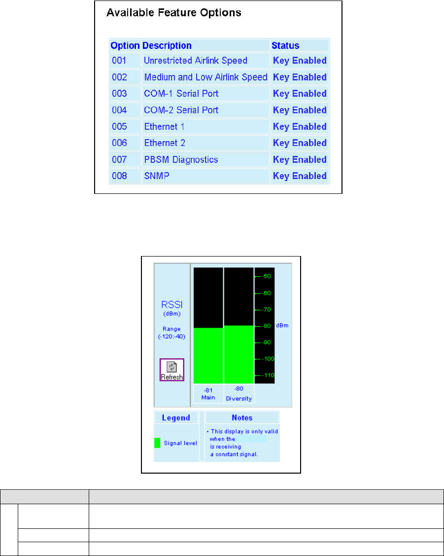
001-2019-500 Rev 0 Paragon4 – UHF, 700 & 800MHz User Manual
79
6.11.5 Maintenance ► Feature Options
Refer to your Dataradio technical support or sales representative for options availability and cost.
Figure 70- Maintenance – Available Feature Options
6.11.6 Maintenance ► RSSI Display
Figure 71 - Maintenance – RSSI Display
Item Description
RSSI
RSSI Table Main -120 = dBm value from main radio receiver
Diversity -120 = dBm value from diversity radio
Range -120 to –40 dBm
Thresholds -90 to -60 dBm
Paragon4
Preliminary
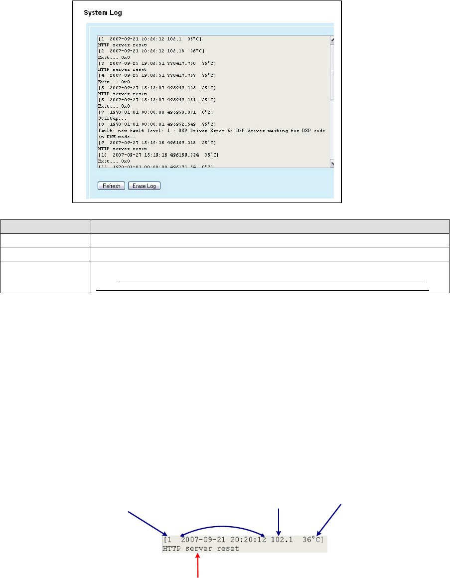
001-2019-500 Rev 0 Paragon4 – UHF, 700 & 800MHz User Manual
80
6.11.7 Maintenance ► System Log
Figure 72 - Maintenance –System Log
Item Description
System Log Records critical events resulting from unexpected conditions during the unit operation.
Refresh Updates the screen to reveal latest log entries.
Erase Log
Deletes all log entries (lost forever).
Note: The system log is a limited reserved area of the flash memory. Once full, the new
events will not get recorded. It is recommended to perform an Erase Log every so often.
6.11.7.1 Reading the Log Entries
The system log records critical events resulting from unexpected conditions during Paragon4 base station
operation. Information from this system log can be useful in understanding specific issues. Have the re-
sulting indications handy if contacting Dataradio support.
A system log entry contains the following parts (see Figure 73):
• A record number,
• A time stamp,
• Time in MSec since last unit rest,
• Chassis temperature, and
• The event itself
Figure 73 - A system Log Entry
Record
Number
Time Stamp
Time in Msec
since last unit
reset
Chassis
Temperature
Event
Preliminary
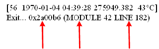
001-2019-500 Rev 0 Paragon4 – UHF, 700 & 800MHz User Manual
81
Note:
Log information will be preserved across system restarts or faults.
The general categories of events that can be found in the system log are:
• Asserts: undesirable conditions (faults)
• Resets: reasons for various system resets
• Others: warnings, recovery from a fault, etc
6.11.7.1.1 Asserts
An Assert log entry will normally display an exit code, a module number, and a line number indicating
where the error occurred. See Figure 74 for an example of an Assert log entry. This information will al-
low Dataradio support team to determine the component and the reason of an error so that a corrective
action could be recommended.
Figure 74 - An Assert type system log entry
Note:
“0x0” exit code signifies normal (non-faulty) system exit.
6.11.7.1.2 Resets
A Paragon4 unit may be reset manually (through the Web interface, a telnet shell, or SNMP control) or
automatically (as a result of the unit’s own monitoring facilities).
Below are some examples of Reset log entries:
Reset issued by a shell command:
[5 1970-01-01 01:03:45 3827.924 37 C]
stationReset: board hard reset
Reset issued through the WEB Interface:
[10 1970-01-10 21:49:00 856116.827 38 C]
HTTP server reset
[11 1970-01-10 21:49:00 856116.842 38 C]
Exit... 0x0
Reset issued by an SNMP MIB browser:
[14 2007-09-17 16:25:17 631.641 34 C]
SNMP: board hard reset
Module
Number
Line Number
Exit Code
Preliminary
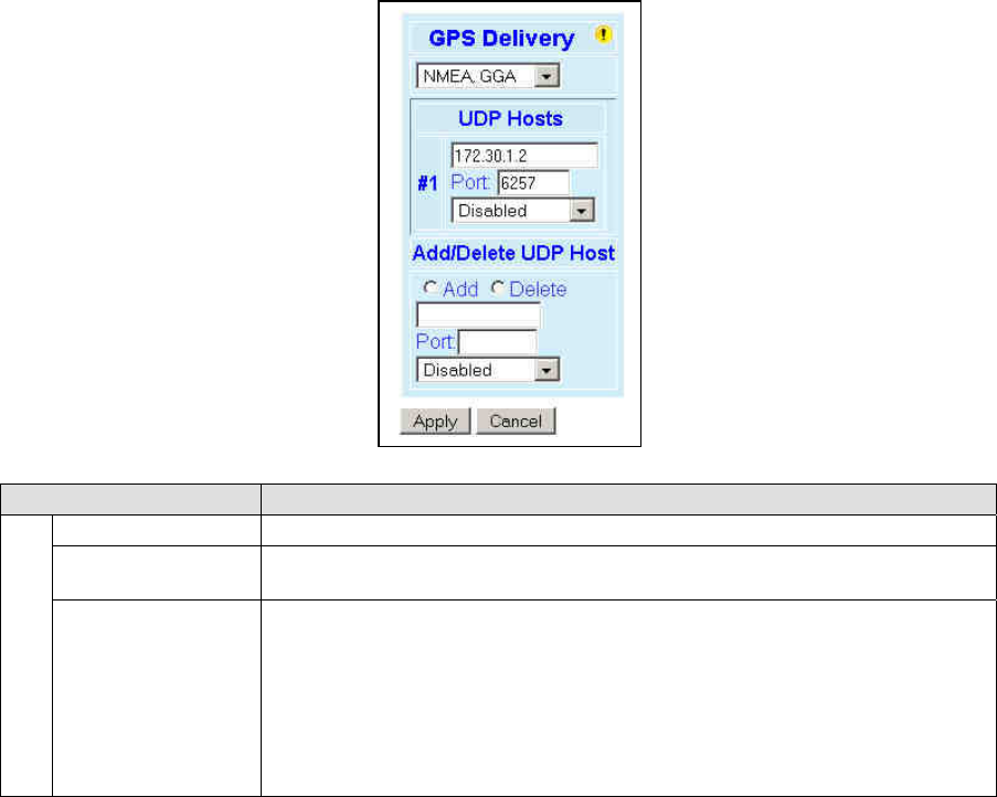
001-2019-500 Rev 0 Paragon4 – UHF, 700 & 800MHz User Manual
82
6.11.7.1.3 Other
Other log entries may be warnings, faults on temporary conditions that can later be recovered, recovery
from faults, or other abnormal conditions.
6.12 OOB Data (Out of Band GPS delivery)
Figure 75 - Out-Of-Band
Item Description
GPS Delivery
Delivery Options Drop-down box for selecting the desired format for the Local Port GPS data delivery
UDP Hosts
Dynamic window expands as Hosts are added or shrinks as Hosts are deleted.
(Screen capture shows one UDP Host added – displayed as #1)
Add/Delete UDP Host
Up to five UDP Hosts may be added:
♦ Select the Add or the Delete option button.
♦ Enter dot decimal format address of the Host in the address field box.
♦ Enter port number in the Port field box.
♦ Click on the “Format” drop-down box and select appropriate format for the UDP
Host being added or deleted.
♦ Click on Apply.
Preliminary
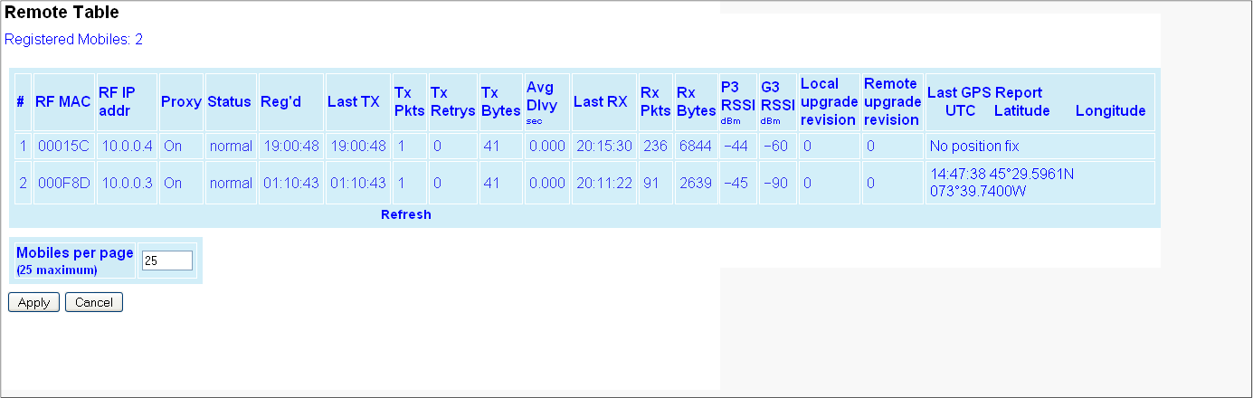
001-2019-500 Rev 0 Paragon4 – UHF, 700 & 800MHz User Manual
83
6.13 Remote Table
Figure 76 - Remote Table
Preliminary

001-2019-500 Rev 0 Paragon4 – UHF, 700 & 800MHz User Manual
84
Item Description
# Index of the displayed entry. Up to 25 entries will be displayed at a time.
“Previous” and “Next” buttons will appear as necessary.
RF MAC RF MAC address of the mobile
RF IP addr RF IP address of the mobile
Proxy Indicates when the TCP Proxy has been enabled for that mobile (On/Off)
Status
Indicates the current state of the mobile. Most common values are:
♦ Normal – Mobile is registered to this base
♦ Handoff – Mobile is roaming to another base
Reg’d Indicates the time the mobile registered on the base
Last TX Indicates the time of last transmitted packet
TX Pkts Count of data packets sent to the mobile
Tx Retrys Count of RETRYs for packets transmitted to the mobile
Tx Bytes Count of bytes transmitted to the mobile
Average Delivery Time
The average time from which an outbound IP message destined for the mobile is presented to
the airlink layer until the RF acknowledgement for that message is received.
Note: The Average Outbound Delivery Time for all mobiles over a period of time is also availa-
ble on the Statistics → Performance page.
Last Rx Indicates the time of the last received packet
Rx Pkts Count of data packets received from the mobile
Rx Bytes Count of bytes received from the mobile
P3 RSSI dBm RSSI (in dBm) of the last data received from the mobile.
G3 RSSI dBm RSSI (in dBm) of a recent data from the base by the mobile
(This information is transmitted to the base along with the GPS report)
Local upgrade revision Number of local updates (incremented when updated locally )
Remote upgrade revision Number of remote parameter updates (incremented when updated over the air)
Last GPS Report:
♦ UTC
♦ Latitude
♦ Longitude
In normal operation, indicates the last Time & Position reports recently transmitted to the base
from the mobile.
Indicates “GPS report missing or not valid” when originally registered if reporting has not yet
begun. Could last up to 3 – 4 minutes.
Indicates “No Fix” when validly reporting and stops receiving valid information.
Preliminary

001-2019-500 Rev 0 Paragon4 – UHF, 700 & 800MHz User Manual
85
6.14 Site Map and Help
Site Map link and Help icon (Figure 77) features are designed to help the user navigate through the Web-
Pages. They can be found on the bottom of the navigation pane.
Figure 77 - Help Icon
Item Description
Site Map Click Site Map link to display a page that hierarchically lists all Web-
Pages on the site and provides a short description where applicable.
Help Icon Click the Help Icon in the navigation pane to open a help text relating to
the window being displayed.
Preliminary
001-2019-500 Rev 0 Paragon4 – UHF, 700 & 800MHz User Manual
86
7. Troubleshooting and Testing
The checks described below should be done at time of installation, annual intervals, or whenever deteri-
oration in performance is noted. These checks are to be done by a CalAmp field service employee, a pro-
fessional installer, or an accredited radio shop technician.
7.1 Equipment Required
• In-line RF power meter in the 0.5W range for the 150 mW exciter module power output*.
Consider wattmeter in the -15W range for the reflected power and in the -50W range for the
forward power of the power amplifier.
*Note: The Crescend PA requires an input power level ranging from 100 to 200mW. The ex-
citer module is therefore adjusted at the factory for 150mW typical.
• Radio service monitor (IFR-120B with option 03: 30 kHz IF filter or equivalent).
• Short RG-223 cable (<2ft) with N-Type male connector to connect the exciter module to the
service monitor if necessary. Short RG-214 cable (<1 foot) with N-Type male connector to
connect the power amplifier module to the service monitor if necessary.
• RF load 50Ω 150W.
Important note: Before proceeding make sure that the service monitor has been calibrated re-
cently and has warmed up for at least the time specified by its manufacturer.
Some reported frequency and deviation problems have actually been erroneous indications from
service monitors that have not adequately warmed up. This is particularly likely when field ser-
vice is done during winter months.
7.2 Recommended Checks
A) After an installation
1. Power-up LED Sequence
2. Transmit power output
3. Reflected power output
4. RF Link test between Paragon4 unit and mobile unit(s) (PING from a PC as per para-
graph 7.4.1)
B) For annual maintenance & trouble-shooting
Same checks as A) plus:
5. Carrier frequency error
6. TX Deviation
7. 12dB SINAD
8. Receiver distortion
9. Main RX and Aux. RX RSSI
10. Verify power supply connections & terminals torque settings (see paragraph 4.4.2.2)
Preliminary

001-2019-500 Rev 0 Paragon4 – UHF, 700 & 800MHz User Manual
87
Table 8 - Checklist A (After installation)
CHECKLIST A
(Paragon4)
Recommended Check out after Installation
Step ACTION EXPECTED RESULTS at 25°C MEASURE WITH IF NOT?
1 Normal Powe
r
-up Sequence
BSC2 PWR LED lights red for up to 5 second, turns amber for up to 5 seconds second,
and stays green thereafter.
TX LED flashes green within 90 seconds after reset
RX LED remains OFF
STATUS LED remains OFF
ETH 1 LED – if connection present – lights green. Flashes amber with activity
ETH 2 LED – If connection present – lights green. Flashes amber with activity
RX POWER and LOCK LEDs must remain steady green
TX
POWER and LOCK LEDs must remain steady green
ON LED lights red for one second, turns OFF for 10 seconds, and stays red the-
reafter
For steps below, refer to Radio (RF Tests) Web Page
2 Power Amplifier
Output Power
Under Test Tone sec-
tion select
Unmodulated
and click Execute
UHF: 100W
(factory configurable from 50W)
700 or 800 MHz: 70 watts
(factory configurable from 35W)
Tolerance: +15% -20%
Service monitor set to
read power
or
150W in-line wattme-
ter installed as close
as possible to the unit
antenna connector.
Verify if PA front
panel LEDs are
off, except PWR
LED on green.
If not 1Check for
bad connections,
damaged coax
cable, etc.
Also check power
at exciter module
output. Should be
in the range of
100-200mW.
If OK, PA may be
at fault. Contact
CalAmp support.
3 Transmitter Reflected
Power
Under Test Tone sec-
tion select
Unmodulated
and click Execute
< 5% of forward power or as speci-
fied by System Engineering. 15W in-line wattmeter
Verify if PA front
panel LEDs are
all OFF except
PWR LED (green)
If not, check for
bad connections,
damaged coax
cable, etc.
4 RF Link test between Paragon4 unit(s) and mobile unit(s) (PING test as per paragraph 7.4.1)
1 (unless unit has been set a lower value). Note that readings less than 100 watts for UHF or 70 watts for the 700 and
800 MHz models, may be due to losses in cables used for testing. Check also your wattmeter frequency calibration
curve. Do not be too ready to condemn the transmitter or the RF feedline & antenna installation.
Preliminary
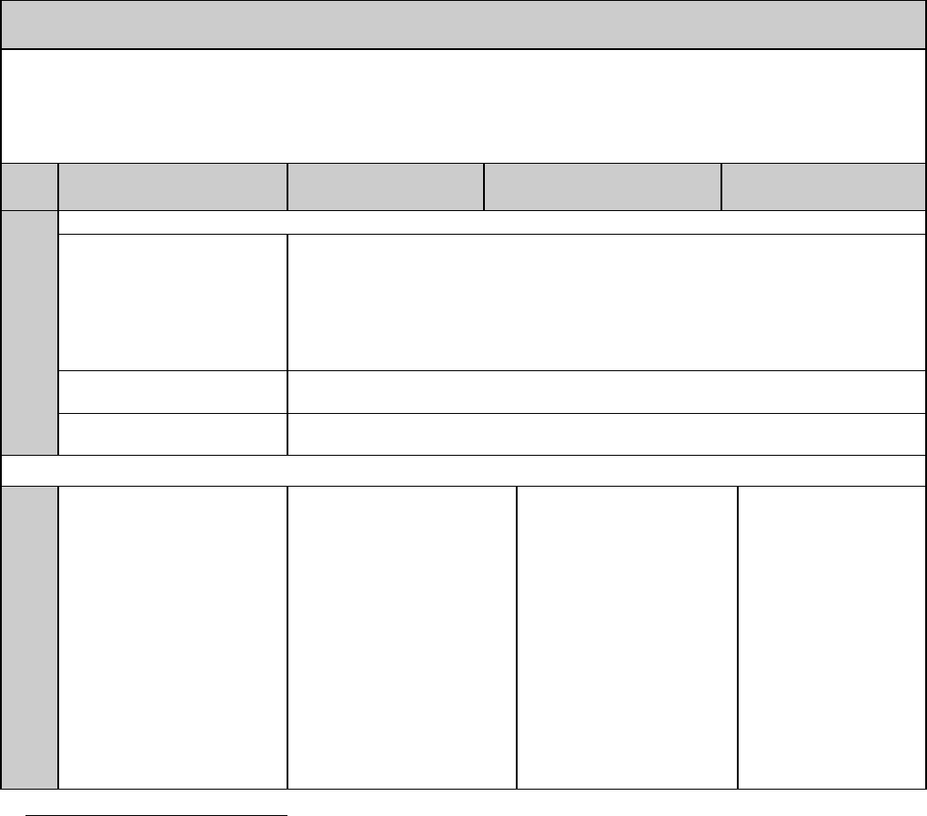
001-2019-500 Rev 0 Paragon4 – UHF, 700 & 800MHz User Manual
88
Table 9 - Checklist B (General)
CHECKLIST B (Paragon4)
General Check out (part1 of 2)
Paragon4 units are set and characterized at the factory to optimize performances.
It is not recommended to try readjusting units unless it is really required.
Misadjusting a unit may result in significant performance losses.
The proposed adjustments in the "IF NOT?" column below, should be tried ONLY if system data performance degra-
dation is noticed combined with out-of-tolerance items.
Step ACTION Expected Results at
25°C
MEASURE WITH IF NOT?
1 Normal Powe
r
-up Sequence
BSC
PWR LED lights red for up to 5 second, turns amber for up to 5 seconds second,
and stays green thereafter.
TX LED flashes green within 90 seconds after reset
RX LED remains OFF
STATUS LED remains OFF
ETH 1 LED – if connection present – lights green. Flashes amber with activity
ETH 2 LED – If connection present – lights green. Flashes amber with activity
RX1 and RX2 PWR and LOCK LED must remain steady green
TX PWR LED and LOCK LED remain steady green
TX LED lights red after 10 seconds, and stays red thereafter
For steps below, on the Radio Î Set Up Web page, press the “test” button to enable Test Tone function
2
Transmitter Output Power
From the Maintenance unit
WEB “Test Tone” page,
Select Unmodulated – and
click Execute
UHF: 100W
(factory configurable from 50W)
700 or 800 MHz: 70 watts
(factory configurable from 35W)
Tolerance: +15% -20%
Service monitor set to read
power
or
150W in-line wattmeter
installed as close as
possible to the unit antenna
connector.
Verify if PA front panel
LEDs are off, except
PWR LED on green.
If not 1Check for bad
connections, damaged
coax cable, etc.
Also check power at
exciter module output.
Should be in the range
of 100-200mW.
If OK, PA may be at
fault. Contact CalAmp
support.
1 (unless unit has been set a lower value). Note that readings less than 100 watts for UHF or 70 watts for the 700 and
800 MHz models, may be due to losses in cables used for testing. Check also your wattmeter frequency calibration
curve. Do not be too ready to condemn the transmitter or the RF feedline & antenna installation.
Preliminary

001-2019-500 Rev 0 Paragon4 – UHF, 700 & 800MHz User Manual
89
3 Transmitter Reflected
Under Test Tone section
select
Unmodulated
and click Execute
< 5% of forward power or as
specified by System Engi-
neering. 15 W in-line wattmeter
Verify if PA front panel
LEDs are all OFF ex-
cept PWR LED (green)
Check for bad connec-
tions, damaged coax
cable, etc.
4 RF Link test between Paragon4 unit and mobile unit(s) (PING test from the unit Web page as per paragraph 6.11.1
or PING from a PC as per paragraph 7.4.1)
5 Carrier Frequency Error
Under Test Tone section
select
Unmodulated
and click Execute
< ±300 Hz @ 25oC ambient
or
< ±1 ppm from –30 to +60 oC
< ±0.1*) ppm –30 to +60 oC
Service monitor set to read
frequency error. *)0.1 ppm
requires the 10MHz refer-
ence option to be present
and instrument’s time gate
set to 1s
If the carrier frequency
error is found to be
out-of-specs, contact
CalAmp support.
6 TX Deviation (kHz)
Under Test Tone section
select
Modulated
and click Execute
Carrier will be modulated with
a 1 kHz tone.
Refer to 7.3.1 for TX
Deviation details.
Tolerance is +5%,
-10% for all bit rates.
Service monitor set to read
deviation.
(IF filter set to Mid or 30 kHz
position) If the TX deviation is
found to be out-of-specs,
contact CalAmp support.
Preliminary

001-2019-500 Rev 0 Paragon4 – UHF, 700 & 800MHz User Manual
90
CHECKLIST B (Paragon4) cont’d
General Check out (part 2 of 2)
Step ACTION Expected Results at 25°C MEASURE WITH IF NOT?
7 12 dB SINAD
(Wide band measurement
method: no audio filtering)
Using a 1KHz tone, set TX
deviation to ±1.5 kHz for a
12.5KHz channel,
±3.0 kHz for a 25KHz
channel and ±6.0 kHz for a
50KHz channel..
Better than -109 dBm for
12.5KHz channel, -110 dBm for
25KHz channel and -108 dBm
for 50 KHz channel using a 2ft
RG-223 coax cable.
- Backplane corresponding
to the receiver being veri-
fied: J18 pin 1 for RX1 or
J19 pin1 for RX2 (see
Figure 425). GND pin
available at TP33
- Service monitor (IFR) set
to SINAD
- IFR IF filter set to MID
position or 30 kHz wide
filter.
If the 12 dB SINAD is
found to be out-of-
specs, check for bad
connections, damaged
coax cable, etc.
If not OK, contact
CalAmp support.
8 Receiver distortion
(Wide band measurement
method: no audio filtering)
Set service monitor RF Gen
output to –70 dBm.
Using a 1KHz tone, set TX
deviation to ±1.5 kHz for a
12.5KHz channel,
±3.0 kHz for a 25KHz chan-
nel and ±6.0 kHz for a
50KHz channel.
≤ 3 %
- Backplane corresponding
to the receiver being veri-
fied: J18 pin 1 for RX1 or
J19 pin1 for RX2 (see
Figure 4). GND pin
available at TP33
- Service monitor (IFR) set
to DISTORTION.
- IFR IF filter set to MID
position or 30 kHz wide
filter.
If the Distortion is
found to be out-of-
specs, check for bad
connections, damaged
coax cable, etc.
If not OK, contact
CalAmp support.
9 RSSI
Apply to each receiver input
the following RF level:
UHF, 700 & 800 MHz:
-80dBm, unmodulated. -Æ
-110dBm, unmodulated. -Æ
UHF, 700 & 800 MHz:
2.75 VDC (±0.2VDC)
1.45 VDC (±0.2VDC)
BSC2 must be connected to
the radio during the
measurements
- Backplane corresponding
to the receiver being veri-
fied: J18 pin 4 for RSSI1
or J19 pin 4 for RSSI2
(see Figure 4). GND pin
available at TP33
- DC Voltmeter measure-
ment
Refer to factory tech-
nical support only if RX
data performance de-
gradation is noticed
combined with out-of-
tolerance RSSI read-
ings.
10
Verify power supply connections & terminals torque settings (see paragraph 4.4.2.2)
Preliminary
001-2019-500 Rev 0 Paragon4 – UHF, 700 & 800MHz User Manual
91
7.3 Additional test details
7.3.1 Carrier Deviations
Carrier Modulation
SRRC4FSK SRRC8FSK SRRC16FSK
Tone Tone Tone
Network
Speed (kb/s)
Typical dev-
iation in kHz Network
Speed (kb/s)
Typical dev-
iation in kHz Network
Speed (kb/s)
Typical dev-
iation in kHz
(1000Hz test
tone) (1000Hz test
tone) (1000Hz test
tone)
Full Channel (UHF) 25 kHz bandwidth
32 ± 3.5 48 ± 4.1 64 ± 4.2
43.2 ± 4.2
Half Channel (UHF) 12.5 kHz bandwidth
16 ± 1.5 24 ± 2.1 32 ± 2.2
Wide Channel (700MHz) 50KHz bandwidth
64 ± 5.8 96 ± 6.7 128 ± 6.7
Full Channel (700MHz) 25KHz bandwidth
32 ± 2.5 48 ± 2.9 64 ± 2.9
43.2 ± 3.0
Half Channel (700MHz) 12.5KHz bandwidth
16 ± 1.3 24 ± 1.4 32 ± 1.5
Full Channel (800MHz) 25KHz Bandwidth
32 ± 2.4 48 ± 2.8 64 ± 2.8
43.2 ± 3.2
NPSPAC Channel (800MHz USA-only) 12.5KHz Bandwidth
16 ± 2.1 24 ± 2.5 32 ± 2.5
Table 10 - Carrier Deviations
7.3.2 PF Switch
Nearly all test “Actions” described in tables 3 and 4 above can be done by selecting the relevant
test tone via the “Radio ► Tests” page of the web interface. However, stopping the Airlink for a
test is done in a different manner. It requires the use of the BSC’s front-mounted PF key rocker
switch (detailed PF operation in the next paragraph). The PF switch can also be used as an alter-
nate way of selecting Test Tones or if a web connection is unavailable.
7.3.2.1 Stopping the Airlink and Alternate Test Tone Selection Method
Located on the BSC module, the PF key is a horizontally mounted rocker switch with a center
detent and spring-loaded positions “1” and “2”. Pressing the switch to posi-
tion “1” causes the “Status” LED to blink green once only followed by
amber blinks at one-second intervals as long as it is held pressed. Pressing
the switch to position “2” is used to select test tones as shown in Table 11
below.
Figure 78 - PF Switch Rocker Detail (one side pressed)
Preliminary

001-2019-500 Rev 0 Paragon4 – UHF, 700 & 800MHz User Manual
92
• If PF is pressed to position “1” for approximately four seconds (visually count the amber
blinks) and released, it brings the Airlink down, PTT is released, no data traffic is sche-
duled, and CWID is suppressed. The Airlink will remain down for a maximum of one
hour and automatically come back up, unless PF is pressed to position “1” once more for
four seconds to force toggle the Airlink to “up” status.
• If PF is pressed to position “1” for approximately one amber blink, PF operation goes in-
to “test mode” where “position 2” is monitored and each successive pressing of position
“2” results in a different test tone selection as detailed in the table below.
• If PF is pressed to position “1” while a test is in progress, PF “test mode” operation is
cancelled.
Note: If PF is not in “monitor mode” pressing to position “2” has no effect.
Table 11 - Test Tones Generation
20-Second Test Tones - PF key generated
For a MODULATED test tone:
Press PF to “1” for approximately 1 amber blink and release. Immediately press PF to “2” one time. Test tone
starts.
To cancel test tone, press PF to “1” and release.
For an UNMODULATED test tone:
Press PF to “1” for approximately 1 amber blink and release. Immediately press PF to “2” two times. Test tone
starts.
To cancel test tone, press PF to “1” and release.
For a SQUARE WAVE test tone:
Press PF to “1” for approximately 1 amber blink and release. Immediately press PF to “2” three times. Test tone
starts.
To cancel test tone, press PF to “1” and release.
For a RANDOM DATA test tone:
Press PF to “1” for approximately 1 amber blink and release. Immediately press PF to “2” four times. Test tone
starts.
To cancel test tone, press PF to “1” and release.
Each pressing at position “2” must be made within one second.
E.g.: For Unmodulated, press twice within 2 seconds, for Random Data, press four times within 4
seconds.
Preliminary
001-2019-500 Rev 0 Paragon4 – UHF, 700 & 800MHz User Manual
93
7.4 Windows/Unix Tools
7.4.1 Network Connectivity
• PING (DOS/WINDOWS)
The ping command determines whether a specific IP address is accessible. It works
by sending a packet to the specified address and waiting for a reply. It is useful for
troubleshooting “end-to-end” reachability, network connectivity, and network laten-
cy.
The ping test is also convenient to verify more specifically the RF link between a
mobile and a known base station
EXAMPLE:
ping 192.168.204.1 –w 3000 displays the response with turn around time
in milliseconds.
• TRACERT (WINDOWS)
The tracert command is used to visually see a network packet being sent and re-
ceived and the amount of hops required for that packet to get to its destination.
Note:
Users with MS-Windows 2000 or XP who need additional information on net-
work latency and network loss may also use the pathping command.
EXAMPLE
tracert www.yahoo.com at the command prompt displays the intermediate
routers between local host to the www.yahoo.com site.
7.4.2 Configuration Information
• IPCONFIG
Ipconfig is a DOS utility which can be used from Command Prompt or a Com-
mand Prompt shell to display the network settings currently assigned and given by a
network. This command can be utilized to verify a network connection as well as to
verify network settings.
EXAMPLE
ipconfig/all at the command prompt displays the Ethernet MAC address, IP
address, IP netmask, default IP gateway, DNS server… information.
• ARP
View and update the system ARP table
The Address Resolution Protocol (ARP) is used with the IP protocol for mapping a
32-bit Internet Protocol address to a MAC address that is recognized in the local net-
work specified in RFC 826. Once recognized the server or networking device returns
a response containing the required address.
Preliminary

001-2019-500 Rev 0 Paragon4 – UHF, 700 & 800MHz User Manual
94
EXAMPLE
arp-a displays all entries in the ARP cache. Useful in manipulating ARP caches.
• ROUTE
View and update the system routing table
The function and syntax of the Windows ROUTE command is similar to the UNIX
or Linux route command. Use the command to manually configure the routes in the
routing table.
EXAMPLE
route ? displays help
route print displays the routing table
7.4.3 Statistics Information
• NETSTAT (WINS & UNIX)
The netstat command symbolically displays the contents of various network-related
data structures, i.e. IP, TCP UDP …
EXAMPLE
netstat ? displays help
netstat -a display TCP and UDP connections and listening ports informa-
tion
For further information on TCP/IP troubleshooting, please visit:
http://www.windowsitlibrary.com/Content/466/14/1.html
7.5 BSC Firmware Upgrading
The Paragon4 radiomodem firmware is field-upgradable using the unit’s Ethernet port. The
process involves connecting to the IP address of the base from a host PC and transferring the
firmware files via an FTP program.
7.5.1 Procedure
1. Using a file decompression program, such as WinZIP™ or WinXP’s right-click & select
the “Expand to…” option, expand the contents of the firmware upgrade package to a di-
rectory of your choice on the host PC.
Warning:
Be aware that base and mobile’s firmware archives are often distributed at the same time.
Files intended for the Paragon4 radiomodem are labeled in the form Para-
gon4_edba_vx.x_Rx.xx.zip. Be careful not to transfer firmware into the wrong unit!
2. Using an FTP client program of your choice, establish a connection to the base IP ad-
dress.
3. Transfer all the files in the upgrade package. Occasionally, long pauses, on the order of
30 to 45 seconds, are possible when storing the file in the unit’s flash file system.
Preliminary
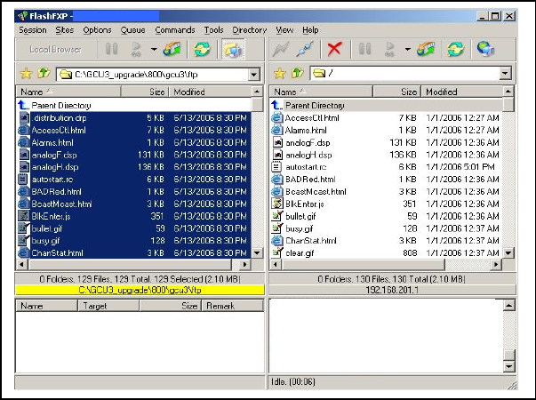
001-2019-500 Rev 0 Paragon4 – UHF, 700 & 800MHz User Manual
95
4. Once the file transfer is complete, cycle the base power and allow the unit to boot. The
unit should return to the state it was in when the update was started.
Note:
After resetting, the PWR LED remaining lit steady amber or red indicates the FTP trans-
fer was not successful or that the firmware is corrupt. Please contact Dataradio system
engineering for assistance.
Figure 79 - Sample FTP program
5. Verify the integrity of the newly transferred files.
a) Connect to the base’s IP address using an Internet browser
b) Enter the user name and password (in the usual manner) and allow the Welcome
page to load.
c) In the left pane, click on Unit Status. The Unit Identification and Status pane should
display the newly upgraded firmware in its Banner (should correspond to the upgrade pack-
age version) and the H/W Status should also show Ok.
d) In the left pane, click on Maintenance, then on Package Control. Wait a few moments
for the results to display.
7.5.1.1 File Integrity Failure
If the message in the result screen points out that file(s) failed the integrity check, retry the FTP
transfer for the failed files(s) again.
If the problem persists, please have the Package Control result screen indications handy and
contact Dataradio system engineering for assistance.
Preliminary

001-2019-500 Rev 0 Paragon4 – UHF, 700 & 800MHz User Manual
96
8. Specifications
GENERAL UHF 700MHz 800MHz
Frequency Range (MHz)
FCC = 406.1 - 512 Rx/Tx
IC = 406.1 - 430 Rx/Tx
IC = 450 - 470 Rx/Tx
FCC = 757 - 758, 763 - 775 Tx
FCC = 787 - 788, 793 - 805 Rx
IC = 764 - 776 Tx
IC = 794 - 806 Rx
FCC = 851 - 869 Tx
FCC = 806 - 824 Rx
IC = 851 - 869 Tx
IC = 806 - 824 Rx
FCC Part 90 & 27 / IC RSS-119
Channel Spacing 12.5 / 25 KHz 12.5 / 25 / 50 KHz NPSPAC / 25 KHz
Mode of Operation Full Duplex, 100% duty cycle
Cabinet Size 22.06” W x 75.82” H (without leveling feet) x 27.06” D
RF/Modem Assembly Size (Rackmount) 19.0” W x 8.75” H x 12.5” D + 2.0” connector allowance
AC/DC Power Supply Assembly Size (Rackmount): 19.0” W x 3.5”H x 16.5” D
Power Amplifier Assembly Size (Rackmount): 19.0” W x 7”H x 6” D
Frequency Stability 1.0 ppm (-30°C to +60°C)
Supply Voltage 120 VAC / 6A max, 60 Hz to 13.8 VDC or
13.8 VDC nominal, negative ground (12.6 to 14.6 VDC range)
Circuit protection
Radio backplane: Main fuse (F1) 10A Blade fuse &
crowbar diodes for reverse polarity protection
Power Amplifier: Fuse protected, overvoltage protected & current limited via AC/DC power
supply or PA power cable with in-line 30A fuse for DC power supply application
RX Current Consumption @ 13.8 VDC 3.0A max. (Two receivers with speaker monitoring)
TX Current Consumption @ 13.8 VDC
24A DC typical @ 25C, 450
MHz & 100W
(26.5A DC max for -30 to
+60C, 403-512MHz & 100W)
22A DC typical @ 25C,
770MHz & 70W
(25A DC max for -30 to +60C,
757-775MHz & 70W
23A DC typical @ 25C,
860MHz & 70W
(26A DC max for -30 to
+60C, 851-869MHz & 70W
Operating Temperature Range
-30°C to +60°C (deleted power supply, catalog number with 0 in second to last digit)
-30°C to +50°C (with standard Heavy Duty Power Supply, catalog number with 2 in second to
last digit)
Modem / Network
User Interface • Dual Ethernet RJ45 Auto MDIX 10-100/T with LED status indicators
• Dual RS-232 DB-9F Serial Ports configured as Terminal Servers
• USB Port (future use)
Addressability Native TCP/IP and built-in router
Data Encryption AES 128-bit
Protocols • Dataradio Proprietary E-DBA with OOB AAVL support
• Ethernet IEEE 802.3, (ICMP, IGMP, TCP, UDP)
• IP Fragmentation, Address Resolution Protocol (ARP)
• IP directed broadcast, IP limited broadcast, IP multicast relay
• DHCP client and server
• Network Address Translation (NAT), Dynamic Routing (RIPv2)
Data rates 12.5 kHz ch.: 25 kHz ch.: 50 kHz ch.: NPSPAC ch.:
32 kbps
24 kbps
16 kbps
64 kbps
48 kbps
43.2kbps
32 Kbps
128 kbps
96 kbps
64 Kbps
32 kbps
24 kbps
16 kbps
Preliminary
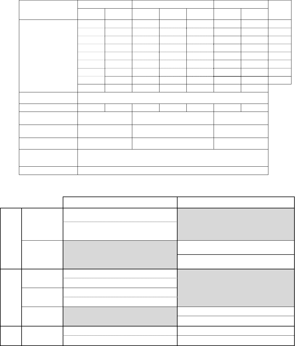
001-2019-500 Rev 0 Paragon4 – UHF, 700 & 800MHz User Manual
97
Radio UHF 700MHz 800MHz Data
rates
(kbps)
25 kHz
Channel
12.5 kHz
Channel
50 kHz
Channel
25 kHz
Channel
12.5 kHz
Channel
25 KHz
Channels
NPSPAC
Channels
Receiver Sensitivity (For
1% Packet Error Rate
(PER) with Parallel Decode
at carrier frequency)
-94 128
-100 96
-98 -106 -95 -95 64
-104 -101 -101 48
-108 -105 -105 43.2
-110 -100 -107 -98 -107 -103 32
-106 -103 -109 24
-109 -110 -115 16
Selectivity >85 dB >67 dB >87 dB >85 dB >67 dB >85 dB >85 dB
Spurious Response Rejec-
tion 100 dB (Typical)
Intermodulation Rejection >83 dB >80 dB >83 dB >83 dB >80 dB >83 dB >83 dB
Receiver Frequency range 406.1 – 512 MHz 787 - 788, 793 - 805 MHz FCC,
794 - 806 MHz IC 806 – 824 MHz
Transmitter Frequency
range 406.1 – 512 MHz 757 - 758, 763 -775 MHz FCC,
764 - 776 MHz IC 851 – 869 MHz
Power Output (field service
adjustable) (50-100W) (35-70W) (35-70W)
Spurious Emissions:-
transmit
-standby
<-36 dBm to 1 GHz, <-30 dBm to 3.2GHz
<-57 dBm to 1 GHz, <-47 dBm to 3.2GHz
VSWR Stability > 5:1 mismatch
FCC / IC
CERTIFICATIONS FCC (Part 90 or 27) IC (DOC, RSS119)
UHF
406.1 - 512 MHz
CWWUHFP10XXUL1 (PA, 100W, 403-470MHz)
TBD (PA, 100W, 450-512MHz)
EOTBDP4-EXCT403 (Exciter, 0.4W, 403-477MHz)
EOTBDP4-EXCT438 (Exciter, 0.4W, 438-512MHz)
406.1 - 430 MHz
450 - 470MHz
7291A-UHFP10XXUL1 (PA, 100W, 403-470MHz)
731A-BDP4EXCT403 (Exciter, 0.4W, 403-477 MHz)
700
MHz
757-758 MHz TBD (PA, 80W)
TBD (Exciter, 0.4W)
769-775 MHz EOTBDP3-CRE700 (PA, 70W, 764-776MHz)
TDB (Exciter, 0.4W)
764 - 776 MHz 773-BDP3CRE7 (70W PA)
TBD (0.4W Exciter)
800
MHz 851 - 869 MHz EOTBDP3-CRE800 (70W PA) 773A-BDP3CRE8 (70W PA)
EOTBDD4-EXT8 (0.4W Exciter) 773A-BDD4-EXT8 (0.4W Exciter)
Preliminary

001-2019-500 Rev 0 Paragon4 – UHF, 700 & 800MHz User Manual
98
EMISSION DESIGNATORS
Bit rate Baud rate Modulation UHF 700MHz 800MHz
128000 32000 SRRC16FSK - 27K0F1D (pending) -
96000 32000 SRRC8FSK - 27K0F1D (pending) -
64000 32000 SRRC4FSK - 27K0F1D (pending) -
64000 16000 SRRC16FSK 16K1F1D (C) 14K0F1D (pending) 13K7F1D (G)
48000 16000 SRRC8FSK 15K8F1D (C) 14K0F1D (pending) 13K7F1D (G)
43200 14400 SRRC8FSK 15K8F1D (C) 14K8F1D (pending) 13K4F1D (G)
32000 16000 SRRC4FSK 16K1F1D (C) 14K0F1D (pending) 13K4F1D (G)
32000 8000 SRRC16FSK 8K30F1D (D) 7K20F1D (pending) 10K0F1D (H)
8K2F1D (D)
24000 8000 SRRC8FSK 8K30F1D (D) 7K20F1D (pending) 10K0F1D (H)
8K2F1D (D)
16000 8000 SRRC4FSK 7K80F1D (D) 7K20F1D (pending) 10K0F1D (H)
8K2F1D (D)
[1] FCC/IC mask G (800MHz, 25kHz ch.)
[2] FCC mask H (800MHz, NPSPAC ch.)
[3] IC mask D (800MHz, 12.5kHz ch.)
[4] FCC/IC mask C (UHF, 25kHz ch.)
[5] FCC/IC mask D (UHF, 12.5kHz ch.)
Preliminary