CalAmp Wireless Networks MCUA5Q User Manual Acrobat Distiller Job 2
CalAmp Wireless Networks Corporation Acrobat Distiller Job 2
UserManual.wiki
>
CalAmp Wireless Networks
>
MCUA5Q User Manual
Users Manual
Navigation menu
Upload a User Manual
Namespaces
Wiki Guide
HTML
PDF
Info
Views
User Manual
Discussion / Help
Navigation
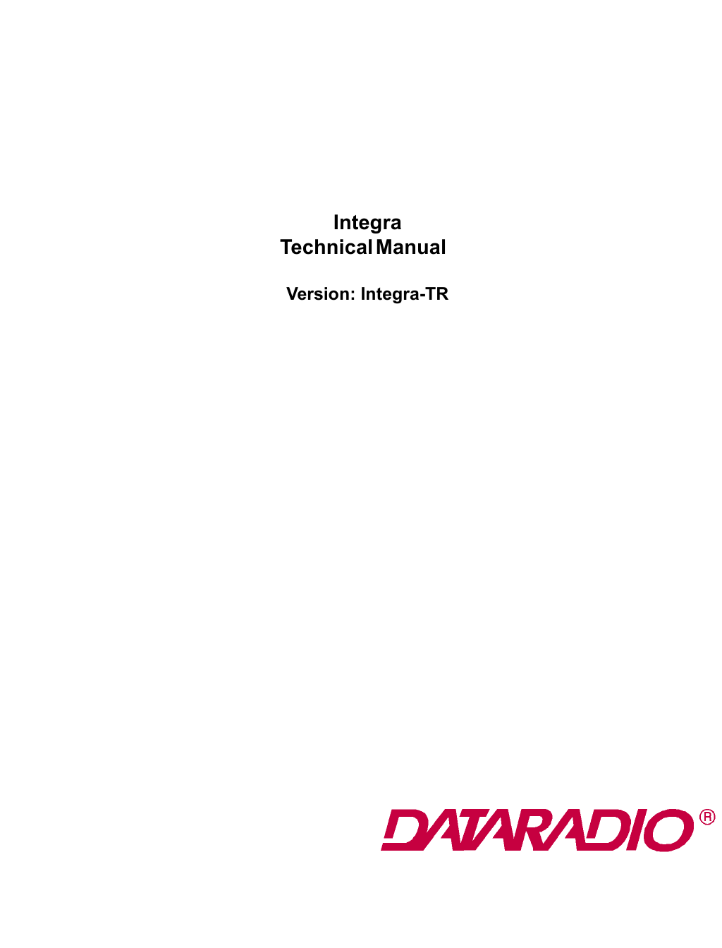
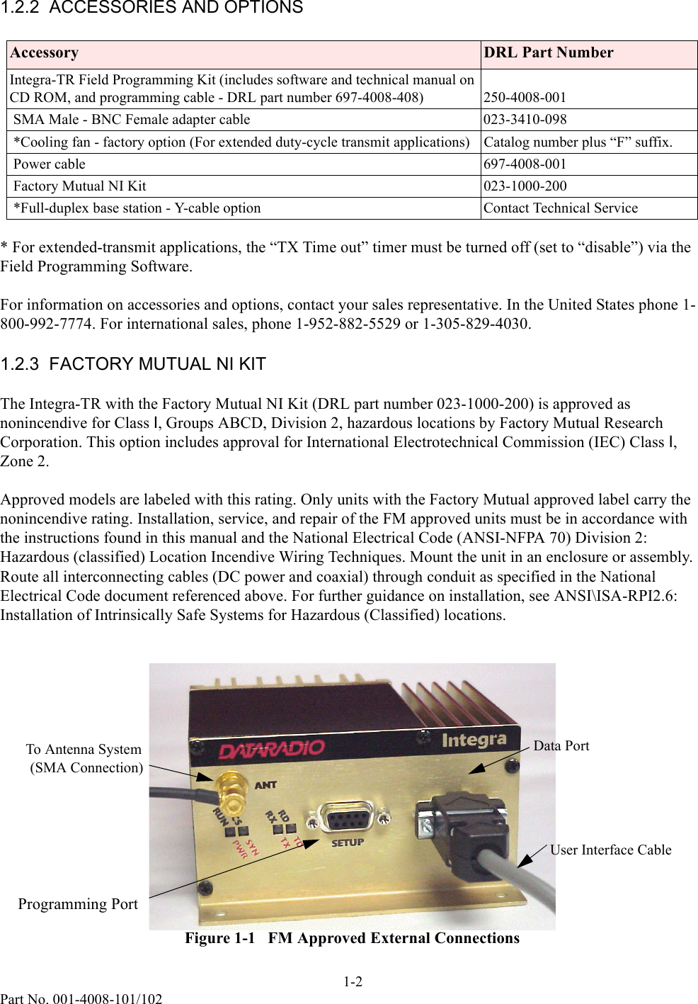
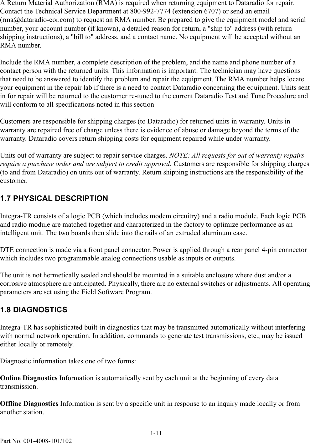
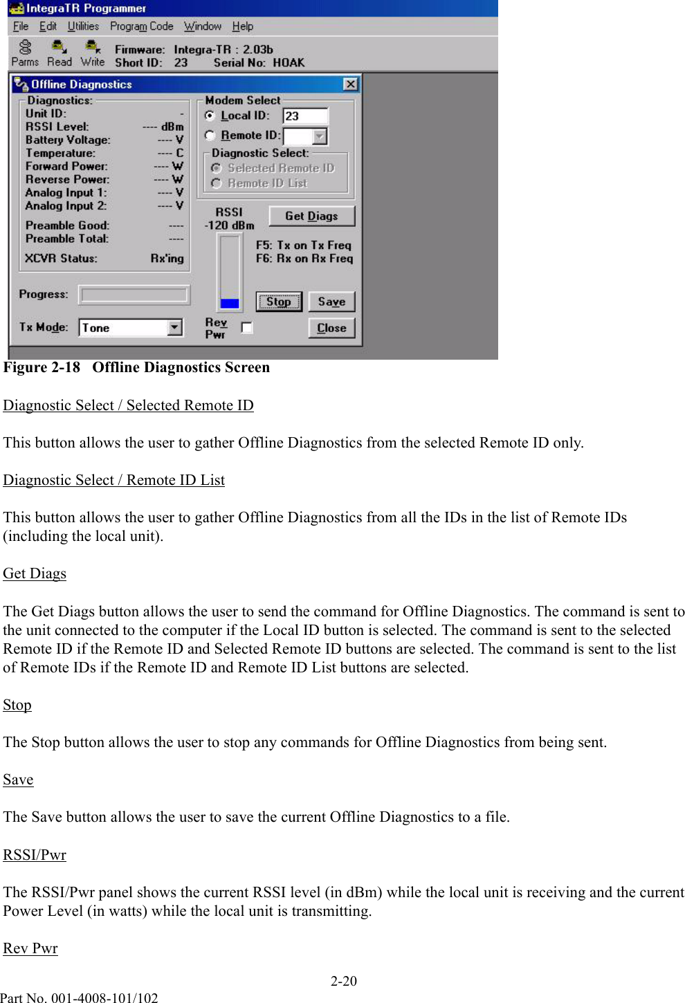
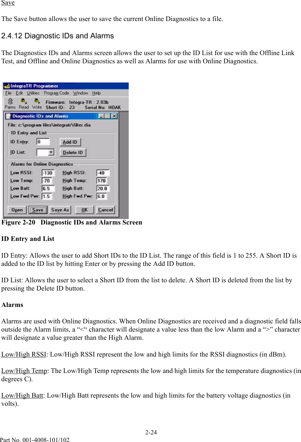
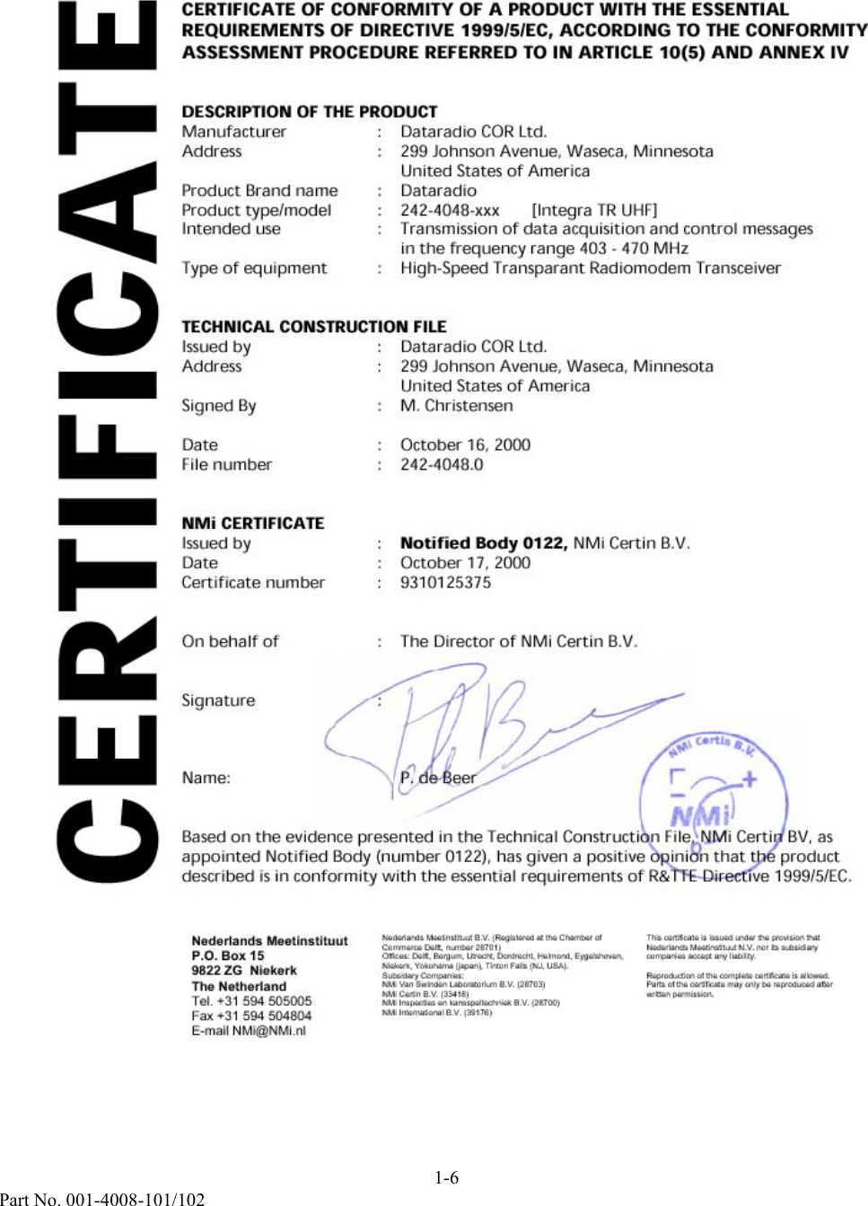
![1-5Part No. 001-4008-101/102Nederlands MeetinstituutP.O. Box 159822 ZG NiekerkThe NetherlandTel. +31 594 505005Fax +31 594 504804E-mail NMi@NMi.nlNederlands Meetinstituut B.V. (Registered at the Chamber ofCommerce Delft, number 28701)Offices: Delft, Bergum, Utrecht, Dordrecht, Helmond, Eygelshoven,Niekerk, Yokohama (japan), Tinton Falls (NJ, USA).Subsidary Companies:NMi Van Swinden Laboratorium B.V. (28703)NMi Certin B.V. (33418)NMi Inspecties en kansspeltechniek B.V. (28700)NMi International B.V. (39176)This certificate is issued under the provision thatNederlands Meetinstituut N.V. nor its subsidiarycompanies accept any liability.Reproduction of the complete certificate is allowed.Parts of the certificate may only be reproduced afterwritten permission.CERTIFICATE OF CONFORMITY OF A PRODUCT WITH THE ESSENTIALREQUIREMENTS OF DIRECTIVE 1999/5/EC, ACCORDING TO THE CONFORMITYASSESSMENT PROCEDURE REFERRED TO IN ARTICLE 10(5) AND ANNEX IVDESCRIPTION OF THE PRODUCTManufacturer : Dataradio COR Ltd.Address : 299 Johnson Avenue, Waseca, MinnesotaUnited States of AmericaProduct Brand name : DataradioProduct type/model : 242-4018-xxx [Integra TR VHF]Intended use : Transmission of data acquisition and control messagesin the frequency range 132 – 174 MHzType of equipment : High-Speed Transparant Radiomodem TransceiverTECHNICAL CONSTRUCTION FILEIssued by : Dataradio COR Ltd.Address : 299 Johnson Avenue, Waseca, MinnesotaUnited States of AmericaSigned By : M. ChristensenDate : October 16, 2000File number : 242-4018.0NMi CERTIFICATEIssued by : Notified Body 0122, NMi Certin B.V.Date : October 17, 2000Certificate number : 9310125372On behalf of : The Director of NMi Certin B.V.Signature :Name: P. de BeerBased on the evidence presented in the Technical Construction File, NMi Certin BV, asappointed Notified Body (number 0122), has given a positive opinion that the productdescribed is in conformity with the essential requirements of R&TTE Directive 1999/5/EC.CERTIFICATE](https://usermanual.wiki/CalAmp-Wireless-Networks/MCUA5Q/User-Guide-162723-Page-7.png)
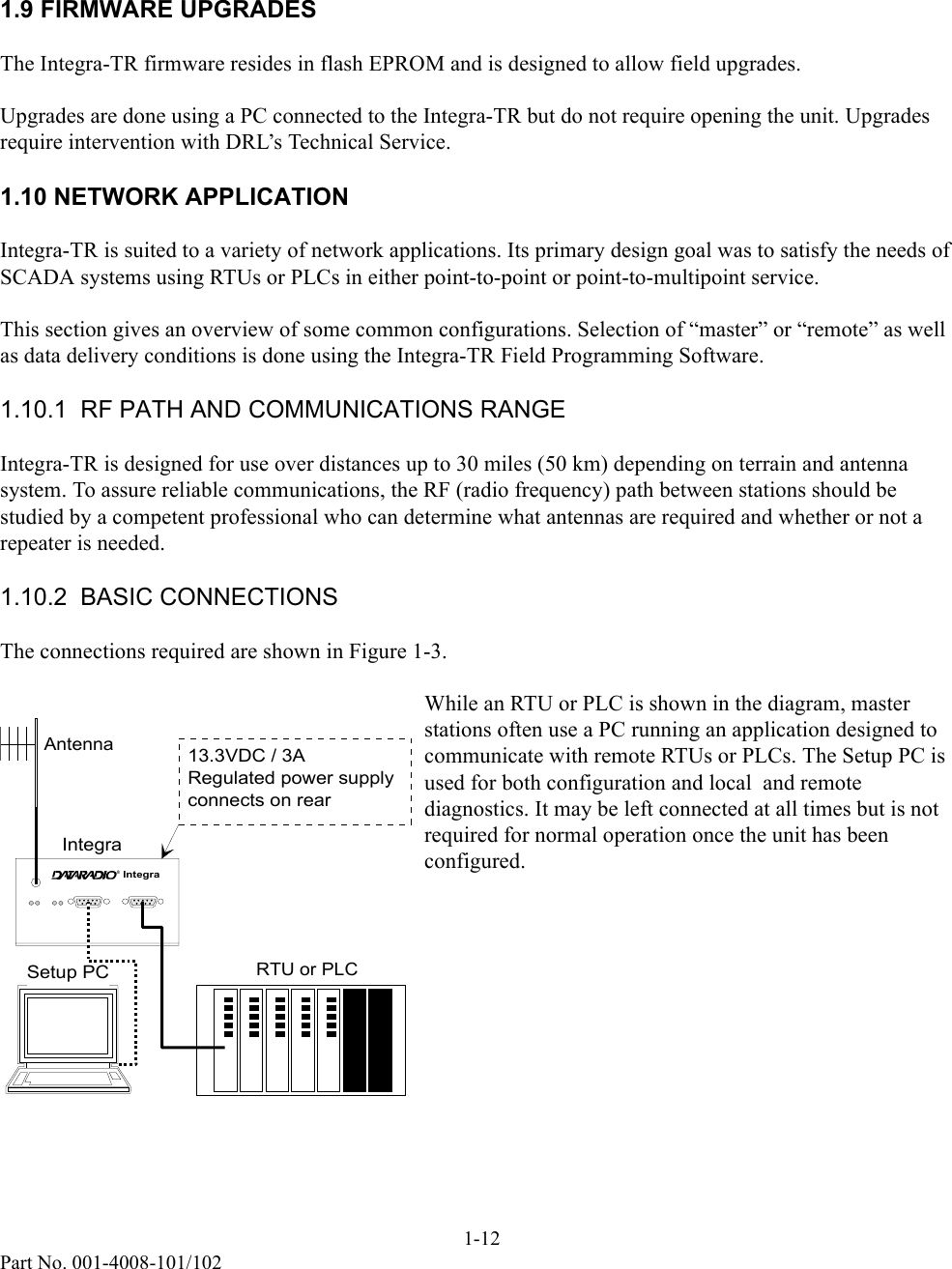
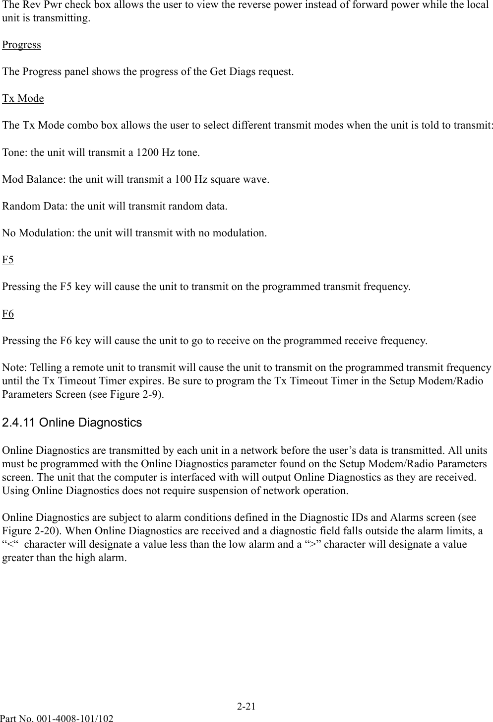
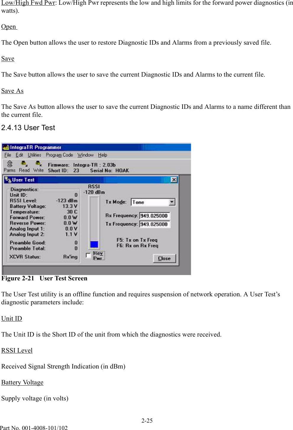
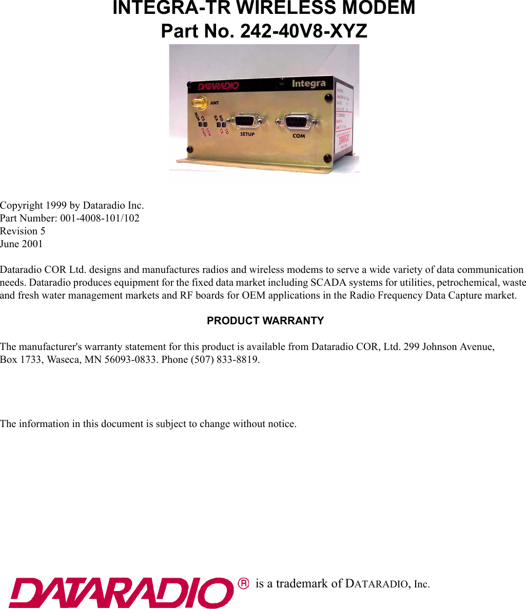
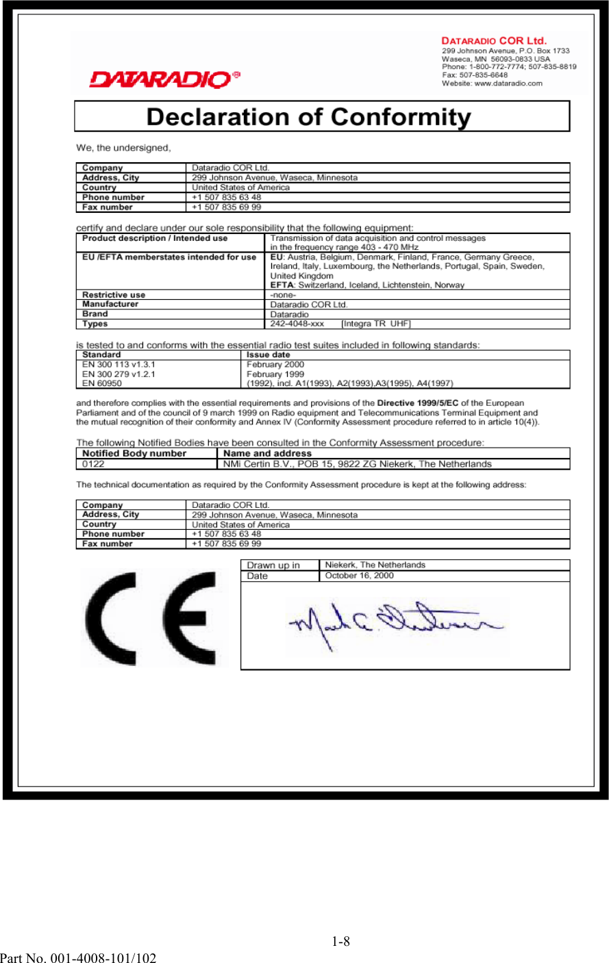
![1-7Part No. 001-4008-101/102 Declaration of Conformity We, the undersigned, Company Dataradio COR Ltd. Address, City 299 Johnson Avenue, Waseca, Minnesota Country United States of America Phone number +1 507 835 63 48 Fax number +1 507 835 69 99 certify and declare under our sole responsibility that the following equipment: Product description / Intended use Transmission of data acquisition and control messages in the frequency range 132 – 174 MHz EU /EFTA memberstates intended for use EU: Austria, Belgium, Denmark, Finland, France, Germany Greece, Ireland, Italy, Luxembourg, the Netherlands, Portugal, Spain, Sweden, United Kingdom EFTA: Switzerland, Iceland, Lichtenstein, Norway Restrictive use -none- Manufacturer Dataradio COR Ltd. Brand Dataradio Types 242-4018-xxx [Integra TR VHF] is tested to and conforms with the essential radio test suites included in following standards: Standard Issue date EN 300 113 v1.3.1 EN 300 279 v1.2.1 EN 60950 February 2000 February 1999 (1992), incl. A1(1993), A2(1993),A3(1995), A4(1997) and therefore complies with the essential requirements and provisions of the Directive 1999/5/EC of the European Parliament and of the council of 9 march 1999 on Radio equipment and Telecommunications Terminal Equipment and the mutual recognition of their conformity and Annex IV (Conformity Assessment procedure referred to in article 10(4)). The following Notified Bodies have been consulted in the Conformity Assessment procedure: Notified Body number Name and address 0122 NMi Certin B.V., POB 15, 9822 ZG Niekerk, The Netherlands The technical documentation as required by the Conformity Assessment procedure is kept at the following address: Company Dataradio COR Ltd. Address, City 299 Johnson Avenue, Waseca, Minnesota Country United States of America Phone number +1 507 835 63 48 Fax number +1 507 835 69 99 Drawn up in Niekerk, The Netherlands Date October 16, 2000 DATARADIO COR Ltd. 299 Johnson Avenue, P.O. Box 1733 Waseca, MN 56093-0833 USA Phone: 1-800-772-7774; 507-835-8819 Fax: 507-835-6648 Website: www.dataradio.com](https://usermanual.wiki/CalAmp-Wireless-Networks/MCUA5Q/User-Guide-162723-Page-9.png)
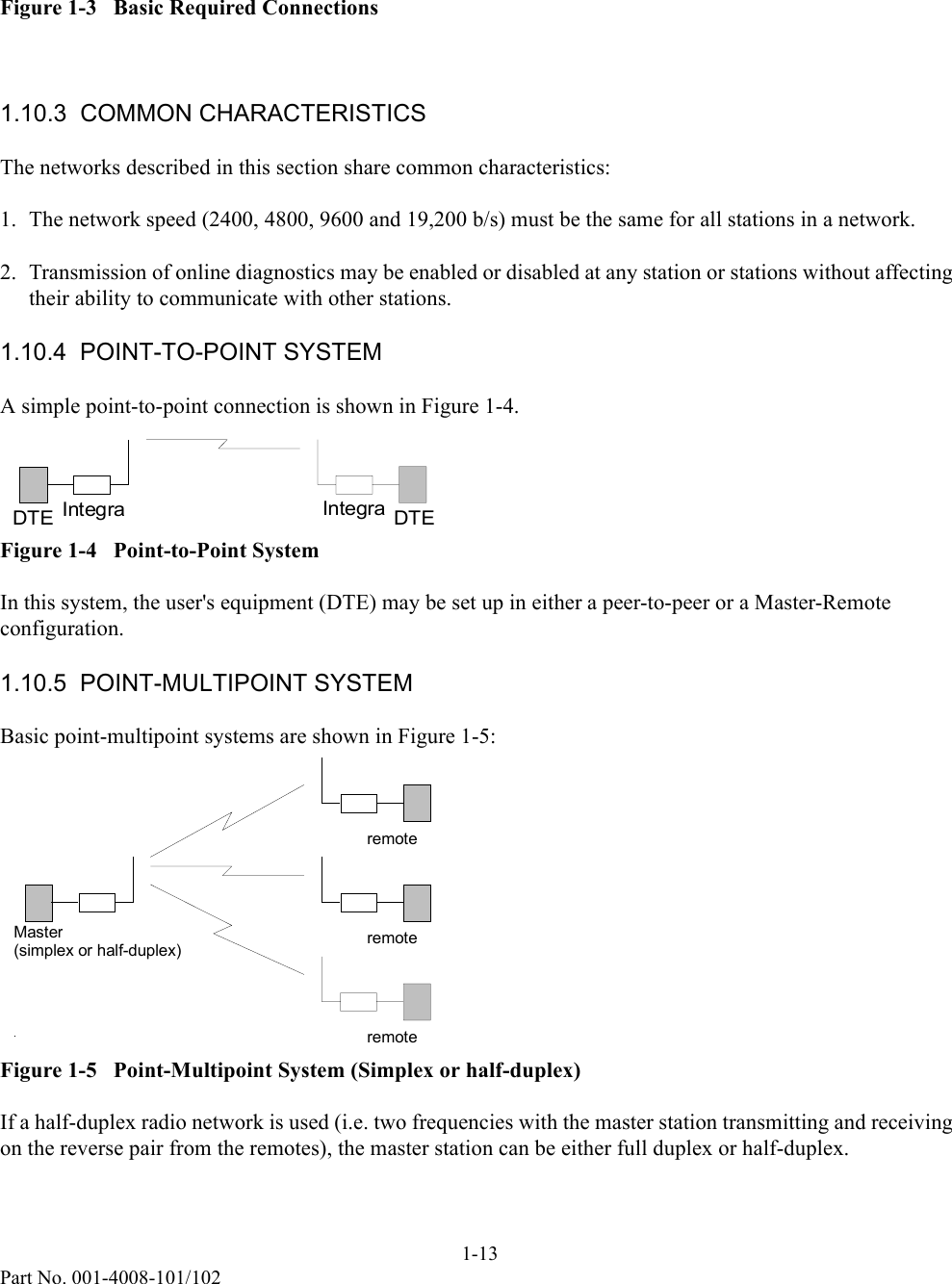
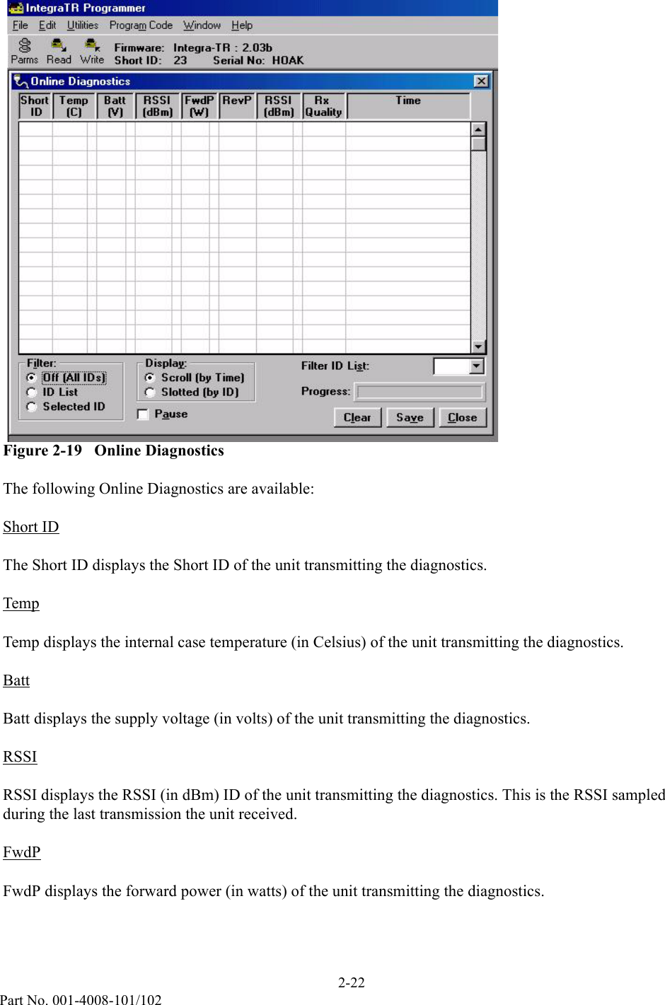
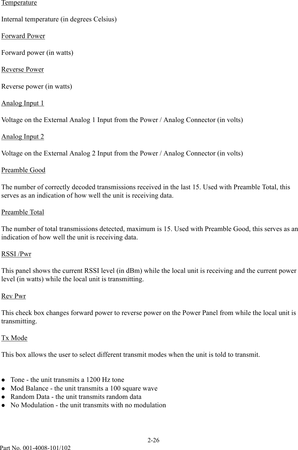
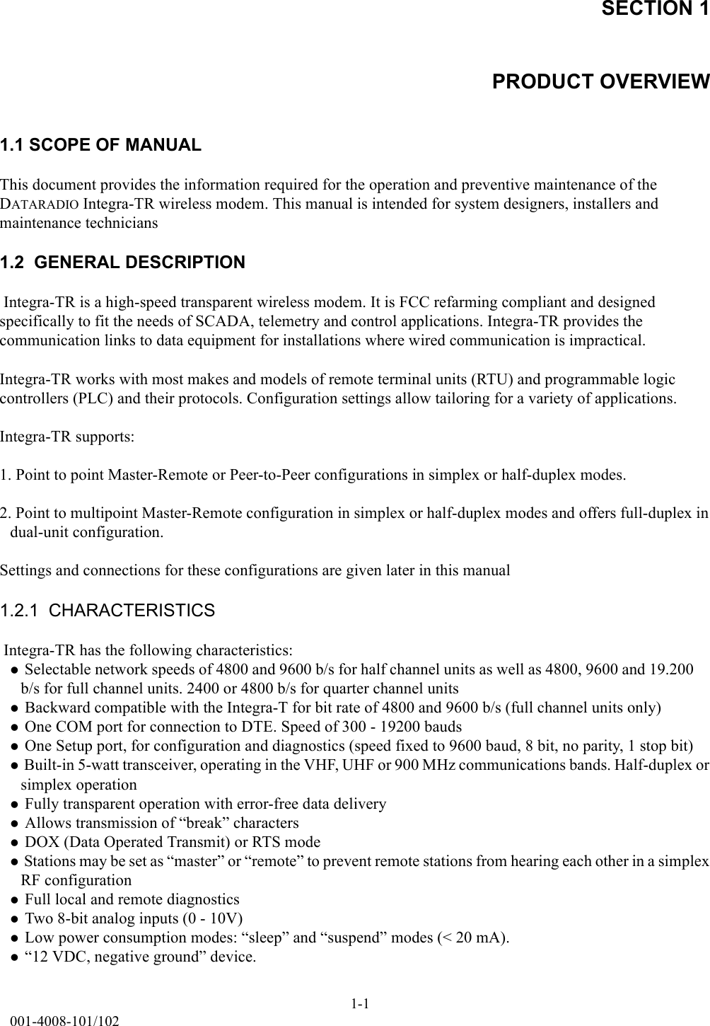
![1-9Part No. 001-4008-101/102 DATARADIO COR Ltd. 299 Johnson Ave, P.O. Box 1733 Waseca, MN 56093-0833 USA Phone: 1-800-992-7774; 507-835-8819 Fax: 507-835-6648 Website: www.dataradio.com Declaration of Product Quality Assurance. In accordance with the Conformity Assessment procedure referred to in article 10(3) of Directive 1999/5/EC of the European Parliament and of the Council of 9 march 1999 on Radio equipment and Telecommunication Terminal Equipment and their mutual recognition of their conformity (R&TTE directive), We, the undersigned, Company DATARADIO COR Ltd. Address, City 299 Johnson Avenue, Waseca, Minnesota Country United States of America Phone number +1 507 835 88 19 Fax number +1 507 835 66 48 certify and declare under our sole responsibility that for the following equipment: Description High-Speed Transparent Radiomodem Transceiver Series Brand / Trademark DATARADIO® Model numbers 242-4016-xxx [T-96SR VHF] 242-4018-xxx [Integra TR VHF] 242-4046-xxx [T-96SR UHF] 242-4048-xxx [Integra TR UHF] manufactured by: Company Dataradio COR Ltd. Address, City 299 Johnson Avenue, Waseca, Minnesota Country United States of America Phone number +1 507 835 88 19 Fax number +1 507 835 66 48 the QA Manual on the following pages describes the philosophy, processes and procedures that are currently in place to confirm that the manufacturing process ensures compliance of the manufactured products with the technical documentation as established by DATARADIO COR Ltd. under the requirements of the R&TTE directive and with the requirements of the R&TTE directive that apply to them. Drawn up in Niekerk, The Netherlands Date 16 October 2000](https://usermanual.wiki/CalAmp-Wireless-Networks/MCUA5Q/User-Guide-162723-Page-11.png)