CalAmp Wireless Networks MCUB5Q Integra-TR DL3412 User Manual Acrobat Distiller Job 2
CalAmp Wireless Networks Corporation Integra-TR DL3412 Acrobat Distiller Job 2
Users Manual

Integra
T e c h n i c a l M a n u a l
Version: Integra-TR
S e r v i c e
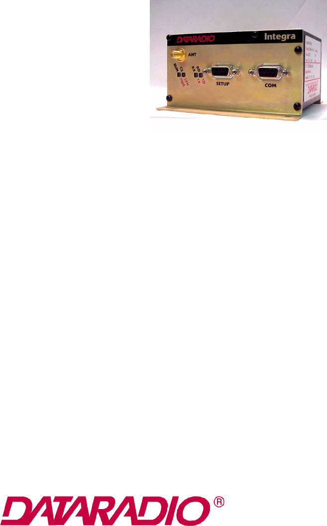
INTEGRA-TR WIRELESS MODEM
Part No. 242-40V8-XYZ
Copyright 1999 by Dataradio Inc.
Part Number: 001-4008-101/102
Revision 5
June 2001
Dataradio COR Ltd. designs and manufactures radios and wireless modems to serve a wide variety of data communication
needs. Dataradio produces equipment for the fixed data market including SCADA systems for utilities, petrochemical, waste
and fresh water management markets and RF boards for OEM applications in the Radio Frequency Data Capture market.
PRODUCT WARRANTY
The manufacturer's warranty statement for this product is available from Dataradio COR, Ltd. 299 Johnson Avenue,
Box 1733, Waseca, MN 56093-0833. Phone (507) 833-8819.
The information in this document is subject to change without notice.
is a trademark of D
ATARADIO
,
Inc.
SECTION 1
PRODUCT OVERVIEW
1-1
001-4008-101/102
1.1 SCOPE OF MANUAL
This document provides the information required for the operation and preventive maintenance of the
D
ATARADIO
Integra-TR wireless modem. This manual is intended for system designers, installers and
maintenance technicians
1.2 GENERAL DESCRIPTION
Integra-TR is a high-speed transparent wireless modem. It is FCC refarming compliant and designed
specifically to fit the needs of SCADA, telemetry and control applications. Integra-TR provides the
communication links to data equipment for installations where wired communication is impractical.
Integra-TR works with most makes and models of remote terminal units (RTU) and programmable logic
controllers (PLC) and their protocols. Configuration settings allow tailoring for a variety of applications.
Integra-TR supports:
1. Point to point Master-Remote or Peer-to-Peer configurations in simplex or half-duplex modes.
2. Point to multipoint Master-Remote configuration in simplex or half-duplex modes and offers full-duplex in
dual-unit configuration.
Settings and connections for these configurations are given later in this manual
1.2.1 CHARACTERISTICS
Integra-TR has the following characteristics:
z
Selectable network speeds of 4800 and 9600 b/s for half channel units as well as 4800, 9600 and 19.200
b/s for full channel units. 2400 or 4800 b/s for quarter channel units
z
Backward compatible with the Integra-T for bit rate of 4800 and 9600 b/s (full channel units only)
z
One COM port for connection to DTE. Speed of 300 - 19200 bauds
z
One Setup port, for configuration and diagnostics (speed fixed to 9600 baud, 8 bit, no parity, 1 stop bit)
z
Built-in 5-watt transceiver, operating in the VHF, UHF or 900 MHz communications bands. Half-duplex or
simplex operation
z
Fully transparent operation with error-free data delivery
z
Allows transmission of “break” characters
z
DOX (Data Operated Transmit) or RTS mode
z
Stations may be set as “master” or “remote” to prevent remote stations from hearing each other in a simplex
RF configuration
z
Full local and remote diagnostics
z
Two 8-bit analog inputs (0 - 10V)
z
Low power consumption modes: “sleep” and “suspend” modes (< 20 mA).
z
“12 VDC, negative ground” device.
1-2
Part No. 001-4008-101/102
1.2.2 ACCESSORIES AND OPTIONS
* For extended-transmit applications, the “TX Time out” timer must be turned off (set to “disable”) via the
Field Programming Software.
For information on accessories and options, contact your sales representative. In the United States phone 1-
800-992-7774. For international sales, phone 1-952-882-5529 or 1-305-829-4030.
1.2.3 FACTORY MUTUAL NI KIT
The Integra-TR with the Factory Mutual NI Kit (DRL part number 023-1000-200) is approved as
nonincendive for Class I, Groups ABCD, Division 2, hazardous locations by Factory Mutual Research
Corporation. This option includes approval for International Electrotechnical Commission (IEC) Class I,
Zone 2.
Approved models are labeled with this rating. Only units with the Factory Mutual approved label carry the
nonincendive rating. Installation, service, and repair of the FM approved units must be in accordance with
the instructions found in this manual and the National Electrical Code (ANSI-NFPA 70) Division 2:
Hazardous (classified) Location Incendive Wiring Techniques. Mount the unit in an enclosure or assembly.
Route all interconnecting cables (DC power and coaxial) through conduit as specified in the National
Electrical Code document referenced above. For further guidance on installation, see ANSI\ISA-RPI2.6:
Installation of Intrinsically Safe Systems for Hazardous (Classified) locations.
Figure 1-1 FM Approved External Connections
Accessory DRL Part Number
Integra-TR Field Programming Kit (includes software and technical manual on
CD ROM, and programming cable - DRL part number 697-4008-408) 250-4008-001
SMA Male - BNC Female adapter cable 023-3410-098
*Cooling fan - factory option (For extended duty-cycle transmit applications) Catalog number plus “F” suffix.
Power cable 697-4008-001
Factory Mutual NI Kit 023-1000-200
*Full-duplex base station - Y-cable option Contact Technical Service
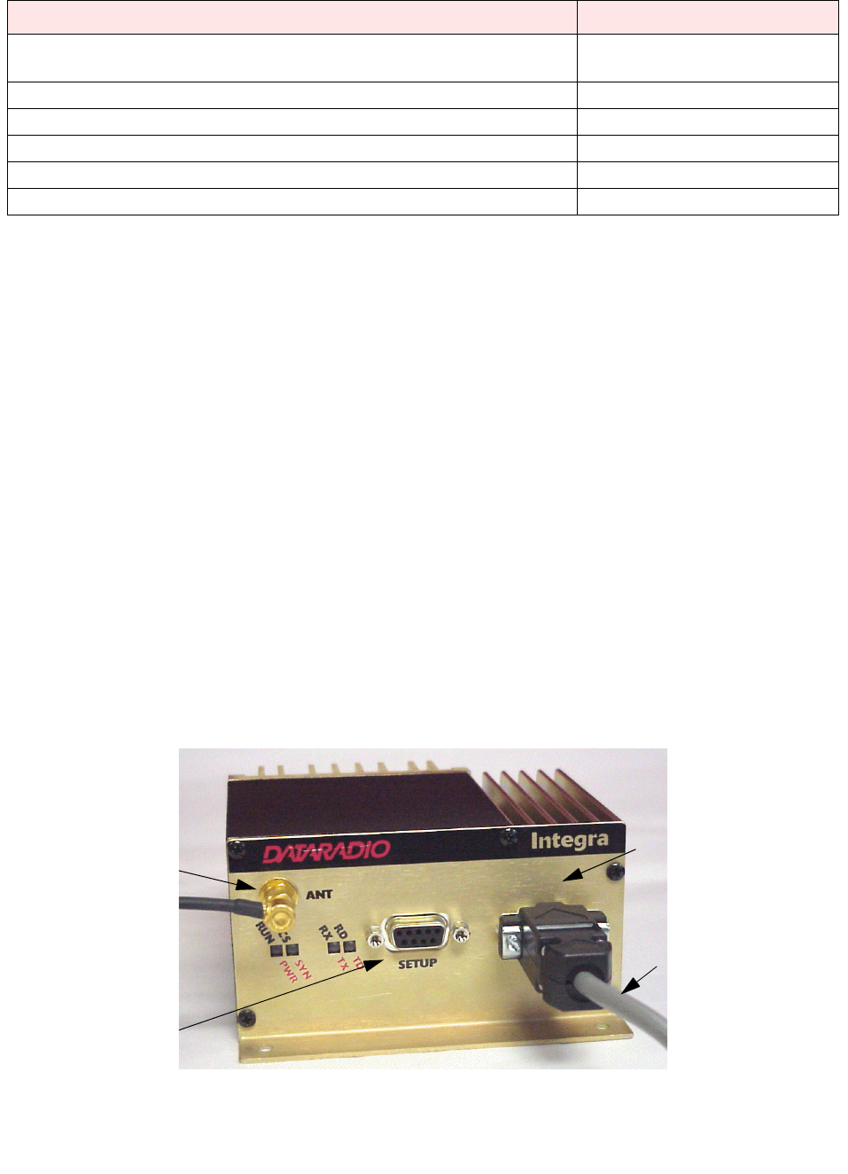
User Interface Cable
Data Port
Programming Port
To Antenna System
(SMA Connection)
1-3
Part No. 001-4008-101/102
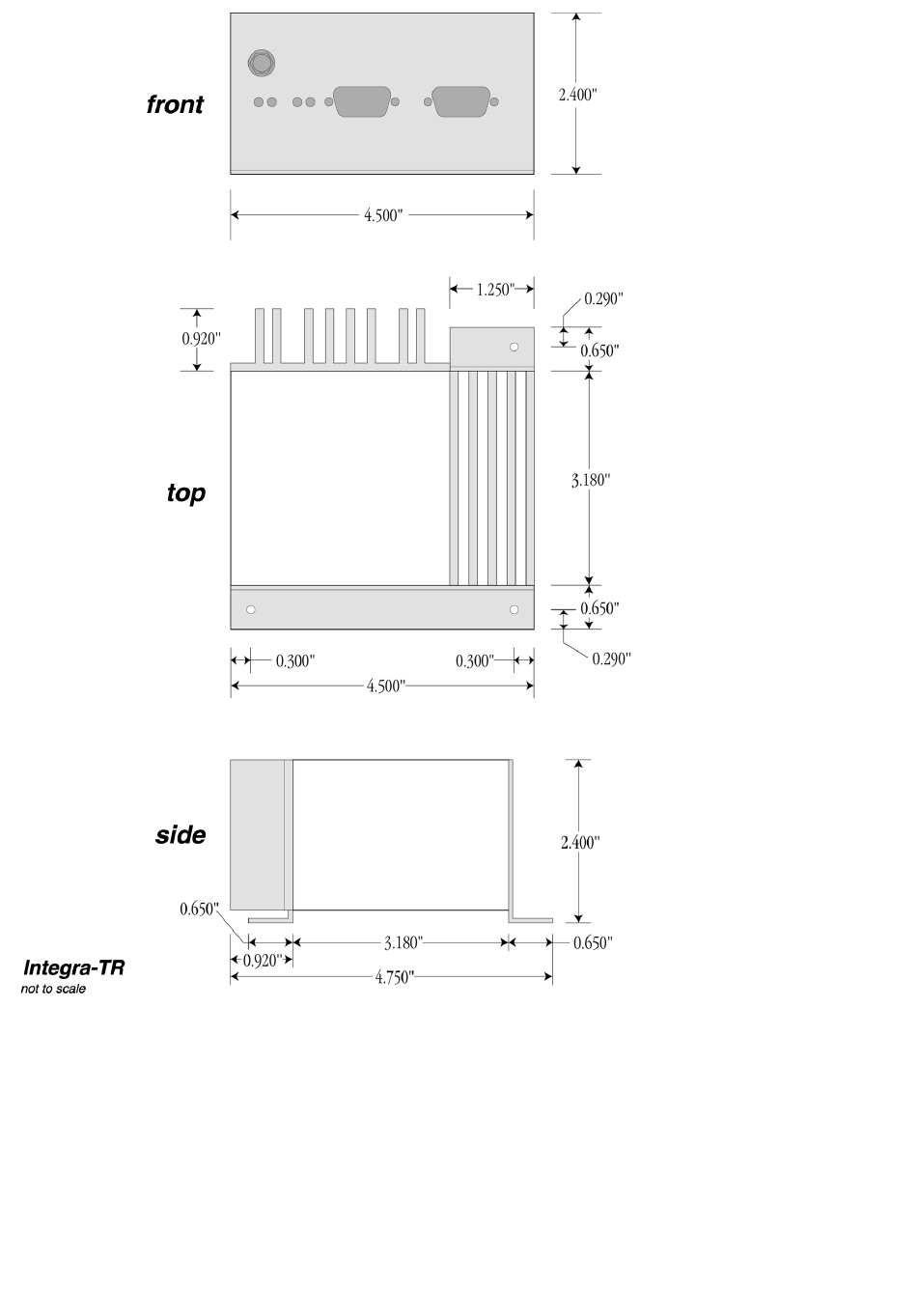
Figure 1-2 Installation Dimensions

1-4
Part No. 001-4008-101/102
1.2.4 INTEGRA-TR CE
Important Notice/Warning on restrictive use in all EU and EFTA member states:
This device is a VHF/UHF Radio data transmitter intended for indoor and outdoor use. Operation of this device is
subject to end-user licence. The end user is strongly advised to contact the local frequency management authorities to
obtain such an end-user licence according to local legislations and frequency allocations. The manufacturer takes no
responsibility for any unauthorized use of this device.
Avis important/Avertissement au sujet de restrictions d’utilisation applicables à l’intérieur d’un pays membre de l’UE
ou de l’AELE :
Cet appareil est un émetteur radio opérant en VHF/UHF, d’usage intérieur ou extérieur, utilisé pour la transmission de
données. L’opération de cet appareil est assujettie aux termes et conditions de la licence émise à l’utilisateur final. Il est
fortement conseillé à l’utilisateur final de contacter les autorités locales légalement responsables de la gestion et de
l’allocation des fréquences radios et d’obtenir auprès d’eux toute licence d’opération requise. Le manufacturier
n’assume aucune responsabilité pour l’usage non réglementaire de cet appareil.
Avvertenza importante per l'uso limitato ai paesi della Comunita' Europea ed EFTA. Questo dispositivo e' un trasmetti-
tore radiofonico di dati di VHF/UHF per uso interno ed esterno. Bisogna avere una licenza per ultilizzare questo dispos-
itivo. Consigliamo fortemente a chi usera' questo trasmettitore di contattare le autorita' locali che amministrano la
gestione delle frequenze per ottenere un'autorizzazione che sia conforme alle leggi locali, e, con questa ottenere l'asseg-
namento della frequenza. Il fornitore di questo dispositivo non e' responsabile per l'uso non autorizzato.
O aviso/advertir importante no uso restritivo estados de todo o membro do EU e do EFTA: Este dispositivo é um
transmissor de rádio dos dados de VHF/UHF pretendido para o uso indoor e ao ar livre. A operação deste dispositivo é
sujeita à licença do end-user. O usuário da extremidade é recomendado fortemente contatar as autoridades locais da
gerência da freqüência para obter tal licença do end-user de acordo com legislações e alocamentos locais da freqüência.
O fabricante das tomadas nenhuma responsabilidade para algum uso desautorizado deste dispositivo.
Advertencia/Noticia: Importante uso restrictivo en Estados miembros de toda la Unión Europea y de Aelc: Este equipo
es un radio transmisor de datos en las bandas de VHF y UHF previsto para uso en interiores y exteriores. La operación
de este equipo es conforme a licencia obtenida por el usuario final. Se aconseja al usurario final que entre en contacto
con las autoridades locales que aprueban el uso de frecuencias, para obtener su propia asignación de frecuencia de
acuerdo a la legislacion de cada pais. El fabricante no se hace responsable del uso de los equipos sin la aprobación de
frecuencia por las autoridades locales.
Wichtige Information/Warnung hinsichtlich Gebrauch in allen EU- und EFTA-Mitgliederstaaten:
Dieses Gerät ist ein VHF/UHF Daten – Funkgerät, daß sowohl innen als auch im Freien betrieben werden kann. Die
Inbetriebnahme dieses Gerätes ist abhängig von einer Nutzerlizenz. Wir empfehlen dem Gerätebetreiber sich mit den
zuständigen Frequenz – Regulierungsbehörden in Verbindung zu setzen, um die entsprechenden Lizenzen, gemäß gültiger
Gesetzgebung, zu beantragen. Der Hersteller dieses Daten – Funkgerätes kann keine Haftung für nicht ordnungsgemäßen
(gesetzeskonformen) Betrieb des Gerätes übernehmen.

1-5
Part No. 001-4008-101/102
Nederlands Meetinstituut
P.O. Box 15
9822 ZG Niekerk
The Netherland
Tel. +31 594 505005
Fax +31 594 504804
E-mail NMi@NMi.nl
Nederlands Meetinstituut B.V. (Registered at the Chamber of
Commerce Delft, number 28701)
Offices: Delft, Bergum, Utrecht, Dordrecht, Helmond, Eygelshoven,
Niekerk, Yokohama (japan), Tinton Falls (NJ, USA).
Subsidary Companies:
NMi Van Swinden Laboratorium B.V. (28703)
NMi Certin B.V. (33418)
NMi Inspecties en kansspeltechniek B.V. (28700)
NMi International B.V. (39176)
This certificate is issued under the provision that
Nederlands Meetinstituut N.V. nor its subsidiary
companies accept any liability.
Reproduction of the complete certificate is allowed.
Parts of the certificate may only be reproduced after
written permission.
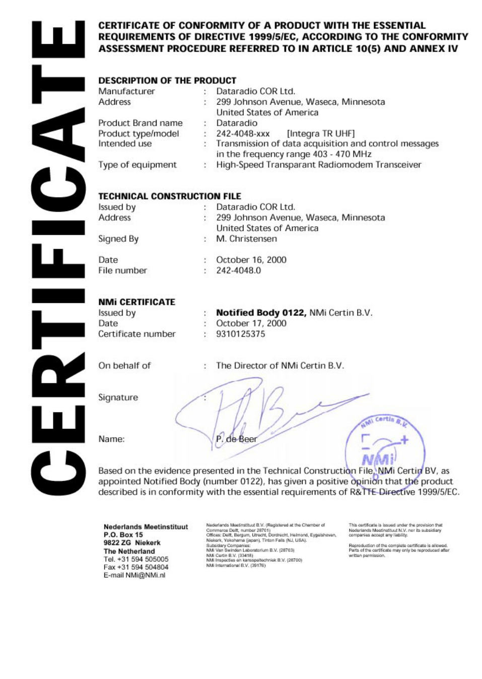
CERTIFICATE OF CONFORMITY OF A PRODUCT WITH THE ESSENTIAL
REQUIREMENTS OF DIRECTIVE 1999/5/EC, ACCORDING TO THE CONFORMITY
ASSESSMENT PROCEDURE REFERRED TO IN ARTICLE 10(5) AND ANNEX IV
DESCRIPTION OF THE PRODUCT
Manufacturer : Dataradio COR Ltd.
Address : 299 Johnson Avenue, Waseca, Minnesota
United States of America
Product Brand name : Dataradio
Product type/model : 242-4018-xxx [Integra TR VHF]
Intended use : Transmission of data acquisition and control messages
in the frequency range 132 – 174 MHz
Type of equipment : High-Speed Transparant Radiomodem Transceiver
TECHNICAL CONSTRUCTION FILE
Issued by : Dataradio COR Ltd.
Address : 299 Johnson Avenue, Waseca, Minnesota
United States of America
Signed By : M. Christensen
Date : October 16, 2000
File number : 242-4018.0
NMi CERTIFICATE
Issued by : Notified Body 0122, NMi Certin B.V.
Date : October 17, 2000
Certificate number : 9310125372
On behalf of : The Director of NMi Certin B.V.
Signature :
Name: P. de Beer
Based on the evidence presented in the Technical Construction File, NMi Certin BV, as
appointed Notified Body (number 0122), has given a positive opinion that the product
described is in conformity with the essential requirements of R&TTE Directive 1999/5/EC.
CERTIFICATE
1-6
Part No. 001-4008-101/102
1-7
Part No. 001-4008-101/102
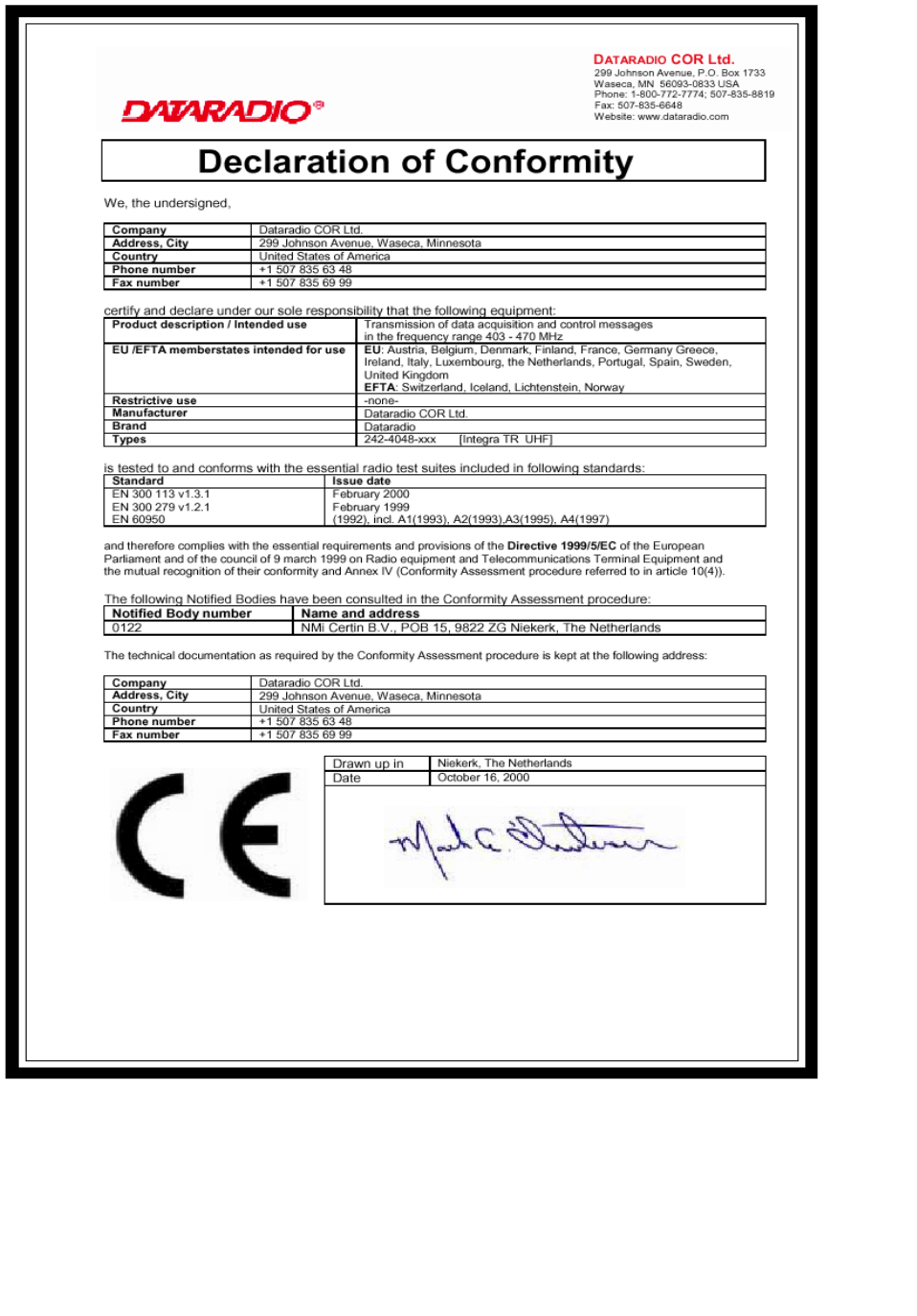
Declaration of Conformity
We, the undersigned,
Company Dataradio COR Ltd.
Address, City 299 Johnson Avenue, Waseca, Minnesota
Country United States of America
Phone number +1 507 835 63 48
Fax number +1 507 835 69 99
certify and declare under our sole responsibility that the following equipment:
Product description / Intended use Transmission of data acquisition and control messages
in the frequency range 132 – 174 MHz
EU /EFTA memberstates intended for use EU: Austria, Belgium, Denmark, Finland, France, Germany Greece,
Ireland, Italy, Luxembourg, the Netherlands, Portugal, Spain, Sweden,
United Kingdom
EFTA: Switzerland, Iceland, Lichtenstein, Norway
Restrictive use -none-
Manufacturer Dataradio COR Ltd.
Brand Dataradio
Types 242-4018-xxx [Integra TR VHF]
is tested to and conforms with the essential radio test suites included in following standards:
Standard Issue date
EN 300 113 v1.3.1
EN 300 279 v1.2.1
EN 60950
February 2000
February 1999
(1992), incl. A1(1993), A2(1993),A3(1995), A4(1997)
and therefore complies with the essential requirements and provisions of the Directive 1999/5/EC of the European
Parliament and of the council of 9 march 1999 on Radio equipment and Telecommunications Terminal Equipment and
the mutual recognition of their conformity and Annex IV (Conformity Assessment procedure referred to in article 10(4)).
The following Notified Bodies have been consulted in the Conformity Assessment procedure:
Notified Body number Name and address
0122 NMi Certin B.V., POB 15, 9822 ZG Niekerk, The Netherlands
The technical documentation as required by the Conformity Assessment procedure is kept at the following address:
Company Dataradio COR Ltd.
Address, City 299 Johnson Avenue, Waseca, Minnesota
Country United States of America
Phone number +1 507 835 63 48
Fax number +1 507 835 69 99
Drawn up in Niekerk, The Netherlands
Date October 16, 2000
DATARADIO COR Ltd.
299 Johnson Avenue, P.O. Box 1733
Waseca, MN 56093-0833 USA
Phone: 1-800-772-7774; 507-835-8819
Fax: 507-835-6648
Website: www.dataradio.com
1-8
Part No. 001-4008-101/102
1-9
Part No. 001-4008-101/102
D
ATARADIO
COR Ltd.
299 Johnson Ave, P.O. Box 1733
Waseca, MN 56093-0833 USA
Phone: 1-800-992-7774; 507-835-8819
Fax: 507-835-6648
Website: www.dataradio.com
Declaration of Product Quality Assurance.
In accordance with the Conformity Assessment procedure referred to in article 10(3) of Directive 1999/5/EC of
the European Parliament and of the Council of 9 march 1999 on Radio equipment and Telecommunication
Terminal Equipment and their mutual recognition of their conformity (R&TTE directive), We, the undersigned,
Company D
ATARADIO
COR Ltd.
Address, City 299 Johnson Avenue, Waseca, Minnesota
Country United States of America
Phone number +1 507 835 88 19
Fax number +1 507 835 66 48
certify and declare under our sole responsibility that for the following equipment:
Description
High-Speed Transparent Radiomodem Transceiver Series
Brand / Trademark
D
ATARADIO
®
Model numbers
242-4016-xxx [T-96SR VHF]
242-4018-xxx [Integra TR VHF]
242-4046-xxx [T-96SR UHF]
242-4048-xxx [Integra TR UHF]
manufactured by:
Company Dataradio COR Ltd.
Address, City 299 Johnson Avenue, Waseca, Minnesota
Country United States of America
Phone number +1 507 835 88 19
Fax number +1 507 835 66 48
the QA Manual on the following pages describes the philosophy, processes and procedures that are currently in
place to confirm that the manufacturing process ensures compliance of the manufactured products with the
technical documentation as established by D
ATARADIO
COR Ltd. under the requirements of the R&TTE directive
and with the requirements of the R&TTE directive that apply to them.
Drawn up in Niekerk, The Netherlands
Date 16 October 2000

1-10
Part No. 001-4008-101/102
1.2.5 CONFIGURATION
Operating characteristics of the Integra-TR are configured by means of Integra-TR's Field Programming
Software. The Field Programming Software is Windows based and requires a Windows95 or later operating
system. Integra-TR requires the use of the Integra-TR Field Programming Software for both configuration
and adjustment.
1.3 FACTORY TECHNICAL SERVICE
The Technical Service Department provides customer assistance on technical problems and serves as an
interface with factory repair facilities. They can be reached in the following ways:
D
ATARADIO
COR Ltd.
299 Johnson Avenue, P.O. Box 1733
Waseca, MN 56093-0833
Technical Service hours are: Monday to Friday 7:30 AM to 4:30 PM, Central Time
Phone: 1-800-992-7774
1-507-833-6701 or 1-507-833-8819
Fax:1-507-833-6748
Email address: support@dataradio-cor.com
1.4 PRODUCT WARRANTY
The warranty statement for the Integra-TR is available by contacting your sales representative. DRL
warranties are included in .pdf format on CD versions of D
ATARADIO
technical manuals.
1.5 REPLACEMENT PARTS
This product is normally not field-serviceable, except by the replacement of complete units. Specialized
equipment and training is required to repair logic boards and radio modules.
Contact Technical Service for information before returning equipment. A Technical Service representative
may suggest a solution eliminating the need to return equipment.
1.6 IF A PROBLEM ARISES...
Component level repair is not recommended on the Integra-TR. DRL’s factory is best equipped to diagnose
problems and make component level repairs. Contact Technical Service before returning equipment. A
technician may suggest a solution eliminating the need to return equipment.
1.6.1 FACTORY REPAIR
Dataradio products are designed for long life and failure-free operation. If a problem arises, factory service
is available. Contact the Technical Service Department before returning equipment. A service representative
may suggest a solution eliminating the need to return equipment.

1-11
Part No. 001-4008-101/102
A Return Material Authorization (RMA) is required when returning equipment to Dataradio for repair.
Contact the Technical Service Department at 800-992-7774 (extension 6707) or send an email
(rma@dataradio-cor.com) to request an RMA number. Be prepared to give the equipment model and serial
number, your account number (if known), a detailed reason for return, a "ship to" address (with return
shipping instructions), a "bill to" address, and a contact name. No equipment will be accepted without an
RMA number.
Include the RMA number, a complete description of the problem, and the name and phone number of a
contact person with the returned units. This information is important. The technician may have questions
that need to be answered to identify the problem and repair the equipment. The RMA number helps locate
your equipment in the repair lab if there is a need to contact Dataradio concerning the equipment. Units sent
in for repair will be returned to the customer re-tuned to the current Dataradio Test and Tune Procedure and
will conform to all specifications noted in this section
Customers are responsible for shipping charges (to Dataradio) for returned units in warranty. Units in
warranty are repaired free of charge unless there is evidence of abuse or damage beyond the terms of the
warranty. Dataradio covers return shipping costs for equipment repaired while under warranty.
Units out of warranty are subject to repair service charges. NOTE: All requests for out of warranty repairs
require a purchase order and are subject to credit approval. Customers are responsible for shipping charges
(to and from Dataradio) on units out of warranty. Return shipping instructions are the responsibility of the
customer.
1.7 PHYSICAL DESCRIPTION
Integra-TR consists of a logic PCB (which includes modem circuitry) and a radio module. Each logic PCB
and radio module are matched together and characterized in the factory to optimize performance as an
intelligent unit. The two boards then slide into the rails of an extruded aluminum case.
DTE connection is made via a front panel connector. Power is applied through a rear panel 4-pin connector
which includes two programmable analog connections usable as inputs or outputs.
The unit is not hermetically sealed and should be mounted in a suitable enclosure where dust and/or a
corrosive atmosphere are anticipated. Physically, there are no external switches or adjustments. All operating
parameters are set using the Field Software Program.
1.8 DIAGNOSTICS
Integra-TR has sophisticated built-in diagnostics that may be transmitted automatically without interfering
with normal network operation. In addition, commands to generate test transmissions, etc., may be issued
either locally or remotely.
Diagnostic information takes one of two forms:
Online Diagnostics Information is automatically sent by each unit at the beginning of every data
transmission.
Offline Diagnostics Information is sent by a specific unit in response to an inquiry made locally or from
another station.
1-12
Part No. 001-4008-101/102
1.9 FIRMWARE UPGRADES
The Integra-TR firmware resides in flash EPROM and is designed to allow field upgrades.
Upgrades are done using a PC connected to the Integra-TR but do not require opening the unit. Upgrades
require intervention with DRL’s Technical Service.
1.10 NETWORK APPLICATION
Integra-TR is suited to a variety of network applications. Its primary design goal was to satisfy the needs of
SCADA systems using RTUs or PLCs in either point-to-point or point-to-multipoint service.
This section gives an overview of some common configurations. Selection of “master” or “remote” as well
as data delivery conditions is done using the Integra-TR Field Programming Software.
1.10.1 RF PATH AND COMMUNICATIONS RANGE
Integra-TR is designed for use over distances up to 30 miles (50 km) depending on terrain and antenna
system. To assure reliable communications, the RF (radio frequency) path between stations should be
studied by a competent professional who can determine what antennas are required and whether or not a
repeater is needed.
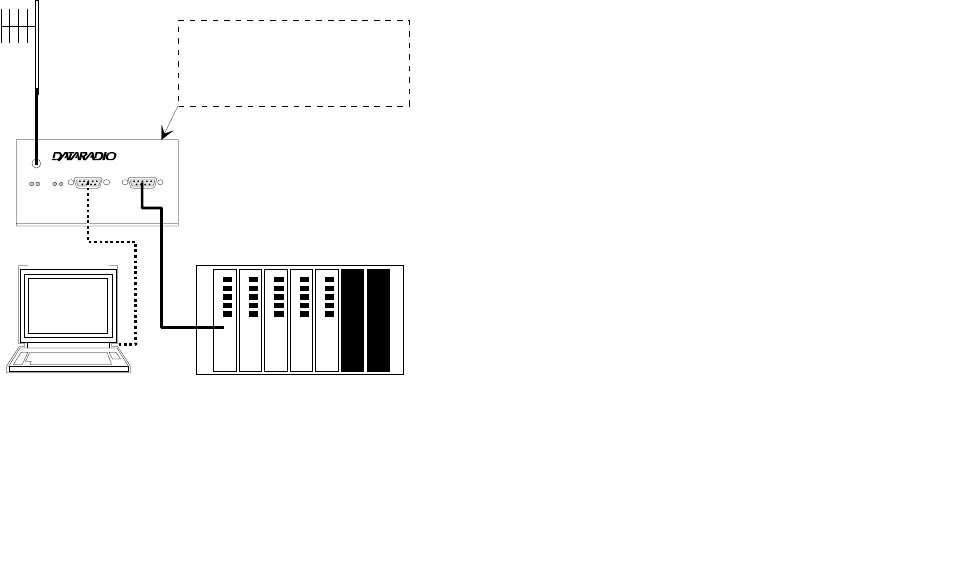
1.10.2 BASIC CONNECTIONS
The connections required are shown in Figure 1-3.
While an RTU or PLC is shown in the diagram, master
stations often use a PC running an application designed to
communicate with remote RTUs or PLCs. The Setup PC is
used for both configuration and local and remote
diagnostics. It may be left connected at all times but is not
required for normal operation once the unit has been
configured.
Integra
®
Antenna
Integra
Setup PC
RTU or PLC
13.3VDC / 3A
Regulated power supply
connects on rear
1-13
Part No. 001-4008-101/102
Figure 1-3 Basic Required Connections
1.10.3 COMMON CHARACTERISTICS
The networks described in this section share common characteristics:
1. The network speed (2400, 4800, 9600 and 19,200 b/s) must be the same for all stations in a network.
2. Transmission of online diagnostics may be enabled or disabled at any station or stations without affecting
their ability to communicate with other stations.
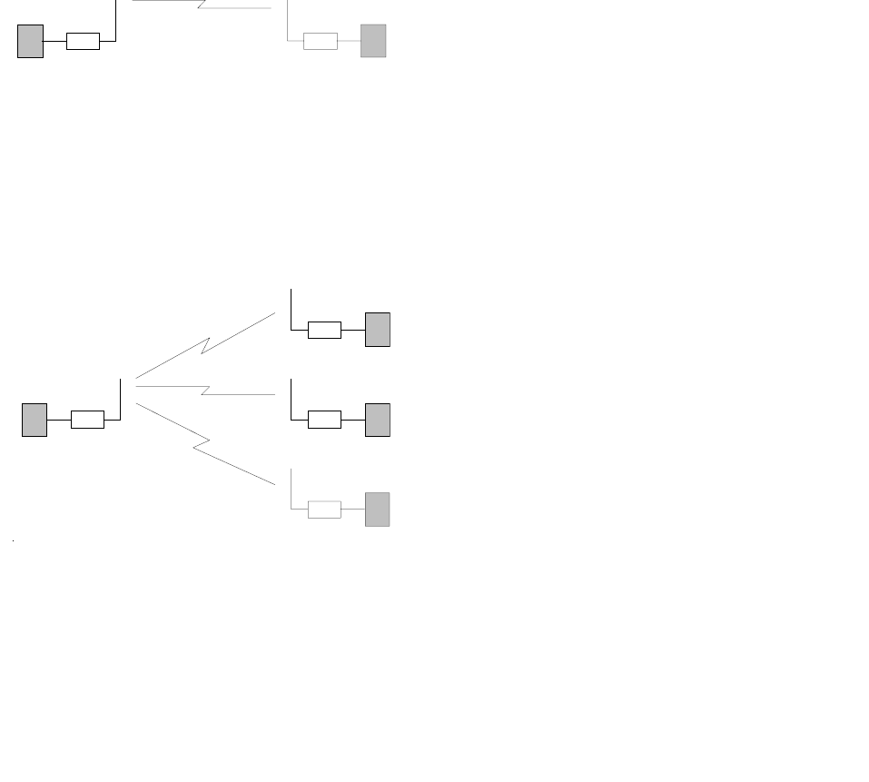
1.10.4 POINT-TO-POINT SYSTEM
A simple point-to-point connection is shown in Figure 1-4.
Figure 1-4 Point-to-Point System
In this system, the user's equipment (DTE) may be set up in either a peer-to-peer or a Master-Remote
configuration.
1.10.5 POINT-MULTIPOINT SYSTEM
Basic point-multipoint systems are shown in Figure 1-5:
Figure 1-5 Point-Multipoint System (Simplex or half-duplex)
If a half-duplex radio network is used (i.e. two frequencies with the master station transmitting and receiving
on the reverse pair from the remotes), the master station can be either full duplex or half-duplex.
DTE Integra DTE
Integra
remote
remote
remote
Master
(simplex or half-duplex)
1-14
Part No. 001-4008-101/102
If a simplex radio network is used (i.e. a single frequency for
all stations), we recommend that the master Integra-TR be set
to “master”, the remotes to “remote” and all units to
“selective” data delivery. This will prevent remote stations
from hearing each other's responses.
For full duplex configuration, set the receiving unit Rx/Tx
Mode to Rx Only (using the Field Programming Software).
Set the transmitting unit mode to Tx Only
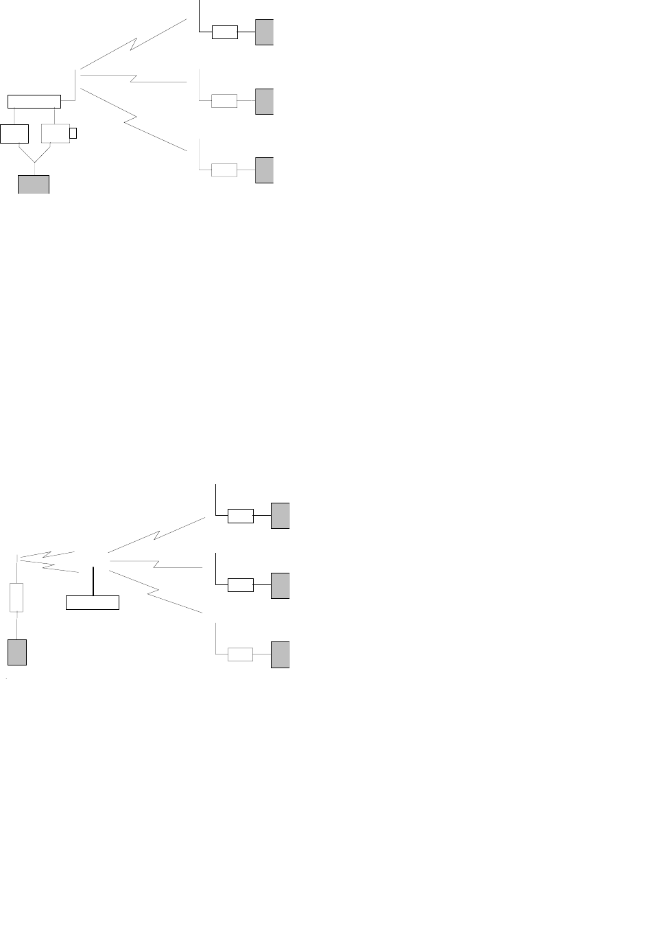
Figure 1-6 Point-Multipoint System (Full-duplex)
Figure 1-7 Point-Multipoint System (Full-duplex Repeater)
remote
remote
remote
Master
(
half-du
p
lex
)
Full-duplex
repeater
Duplexer
remote
remote
remote
RX TX
Y Cabl
e
730 03350-00x
Duplexer
Master
(full-duplex)
Fan
1-15
Part No. 001-4008-101/102
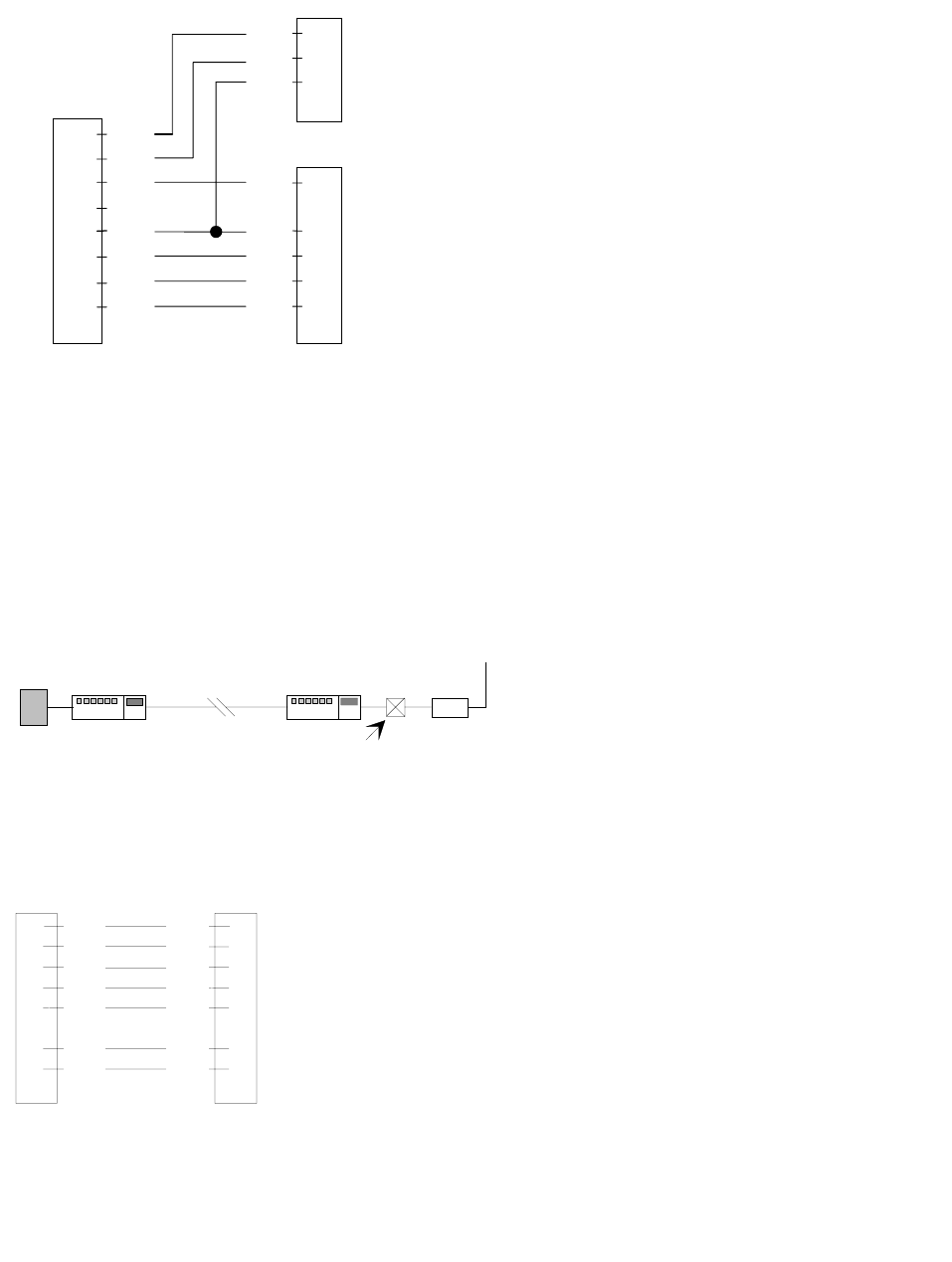
Figure 1-8 Integra-TR Full-duplex Base Station Pinout
1.10.6 EXTENDING A LANDLINE (TAIL CIRCUIT)
Integra-TR may be used to extend a landline circuit (giving access to difficult locations, etc.). This type of
connection is called a “tail circuit” and is shown in Figure 1-9. The tail circuit assembly may be used in any
of the network types described in the preceding sections.
Figure 1-9 Landline (Tail Circuit)
Note: The line modems should be full duplex units.
Figure 1-10 DCE Crossover Cable for RTS-CTS mode
USER
(DTE)
1
2
3
4
5
6
7
8
RX-Unit (DE-9M)TX-Unit (DE-9M)
DCD
RXD
GND
TXD
GND
DSR
RTS
CTS
DCD
RXD
TXD
DTR
GND
DSR
RTS
CTS
1
2
5
3
5
6
7
8
DE-9F
Y-CABLE
line
modem
line
modem
dedicated
line Integra
DTE
DCE crossover
cable
1
2
3
4
5
6
7
8
9
DE-9M
7
3
2
8
5
1
4
DE-9M
DCD
RXD
TXD
DTR
GND
RTS
CTS
RTS
TXD
RXD
CTS
GND
DCD
DTR

1-16
Part No. 001-4008-101/102
Some point-to-point FDX landline modems or line drivers may require the use of DOX mode and an
alternate pinout for DTR, DCD, CTS and RTS as shown in Figure 1-11.
Figure 1-11 DCE Crossover Cable for DOX Mode
1
2
3
7
5
6
4
8
9
DE-9M
4
3
2
8
5
1
7
DE-9M
DCD
RXD
TXD
RTS
GND
DTR
CTS
DTR
TXD
RXD
CTS
GND
DCD
RTS

1-17
Part No. 001-4008-101/102
GENERAL SPECIFICATIONS
These specifications are subject to change without notice.
*380 to 403 MHz frequency band is not FCC or IC type approved
*psophometrically weighted
1
Cold Start: time from DC power applied until unit is fully ready to receive or transmit data
2
Warm Start Rx: in low power modes (sleep or suspend), wake-up time for full receiver recovery
3
Warm Start Tx: in low power modes (sleep or suspend), wake-up time for full transceiver operation
4
Tx Turnon Time: typical Rx to Tx switching time for stable transmission
GENERAL VHF UHF 900 MHz
Frequency 132-174 MHz 380-403 MHz*
403-512 MHz
928-960 MHz
Channels One channel
Channel Bandwidth 6.25 (VHF and UHF only), 12.5, or 25 kHz models
Operating Temperature -30° to + 60° C
Supply voltage 10 - 16 VDC maximum (nominal 13.3)
Fuse protected against reverse voltage (internal surface mount 3A fuse: not field replaceable)
Rx Current Drain at 13.3 VDC <170 mA (with a terminal connected to Integra-TR COM port)
Tx Current Drain at 13.3 VDC <2.0 A <2.5 A
Low Power Mode Current Drain 20 mA
Cold start
1
4 sec (typical)
Warm Start Rx
2
45 to 60 msec (depending on radio model and temperature)
Warm Start Tx
3
55 to 70 msec (depending on radio model and temperature)
Tx Turnon Time
4
15 ms (typical)
Rx/Tx Bandwidth, without tuning 18 MHz (132-150)
24 MHz (150-174)
16 MHz except
20 MHz (450-470)
32 MHz
Nominal Dimensions 4.5" W x 2.2" H x 4.75" D (11.4 x 5.6 x 12.1 cm)
RECEIVER VHF UHF 900 MHz
Sensitivity 0.35 µV for 12 dB SINAD*
Selectivity (25 kHz) 75 dB typical, 70 dB minimum 72 dB typical, 65 dB minimum
Selectivity (12.5 kHz) 65 dB typical, 60 dB minimum 63 dB typical, 60 dB minimum
Selectivity (6.25 kHz) TBD
TBD
N/A
Intermodulation 75 dB typical, 70 dB minimum 72 dB typical, 70 dB minimum
Spurious Rejection 75 dB typical, 70 dB minimum 75 dB typical, 70 dB minimum
FM Hum and Noise -48 dB typical
-45 dB max (25 kHz)
-48 dB typical
-45 dB max (25 kHz)
-43 dB typical
-40 dB max (25 kHz)
Conducted Spurious < -57 dBm
TRANSMITTER VHF UHF 900 MHz
RF Power Output 1 to 5 Watts, software adjustable
Spurious and Harmonics -63 dBc (-26 dBm) typical
-57 dBc (-20 dBm) max.
-75 dBc (-38 dBm) typical
-63 dBc (-26 dBm) max.
-75 dBc (-38 dBm) typical
-57 dBc (-20 dBm) max.
Frequency Stability
12.5 and 25 kHz
6.25 kHz
2.5 PPM
1 PPM
1.5 PPM
1 PPM
1.5 PPM
FM Hum and Noise -50 dB typical (25 kHz)
-45 dB max (25 kHz)
-50 dB typical (25 kHz)
-45 dB max (25 kHz)
-50 dB typical (25 kHz)
-40 dB max (25 kHz)
Attack Time < 7 ms
Tx Duty Cycle 50%, max. Tx time 30 seconds, extended Tx time with the cooling fan option

1-18
Part No. 001-4008-101/102
Modem / Logic
Operation Simplex / half duplex
Data Bit Rates 25 kHz channel: 4800 b/s, 9600 b/s, 19200 b/s
Modulation Type DRCMSK (Differential Raise-Cosine Minimum Shift Keying)
RTS/CTS Delay (RTS mode) 4 ms
Addressing 8 bit station address, 1 bit station type (master / remote)
Bit Error Rate (BER)
2400 b/s 6.25 kHz
4800 b/s 6.25 kHz
9600 b/s, 12.5 kHz
9600 and 4800 b/s, 25 kHz
19200 b/s, 25 kHz
TBD
TBD
1 x 10 -6 at 1.4 µV minimum /-104 dBm
1 x 10 -6 at 1.0 µV minimum / -107 dBm
1 x 10 -6 at 2.3 µV minimum / -100 dBm
COM Port
Interface EIA RS-232C
Data Rate 300 - 19200 b/s
Protocol Transparent, 7 or 8 data bits, 1 or 2 stop bits, even, odd or no parity
Transmit Control RTS or DOX (data operated transmit)
Setup/Diag Port
Data Format Proprietary binary for setup, ASCII for diagnostics
Data Rate 9600 b/s, 8 bit, no parity, 1 stop bit
Analog Inputs
Interface Two inputs, 0-10 VDC, 8 bits. May be read only via offline diagnostics.
Absolute maximum input voltage < 20 Vdc. Inputs are reverse-voltage protected.
Display
4 Bi-color status LEDs RUN/PWR/ CS/SYN, RX/TX, RD/TD
Connectors
RF SMA Female
COM DE-9F
SETUP/DIAG DE-9F
Power/Analog Snap & Lock 4-Pin DC Power Jack
Diagnostics
Online Short ID, temperature, B+ voltage, local RSSI, remote RSSI, fwd and rev
power, Rx Quality
Offline As for Online plus: Demodulated Signal Voltage, Analog Input Levels
FCC / IC Certifications
FCC 6.25 kHz FCC 12.5 & 25 kHz IC (DOC)
VHF NP4MCUA5Q
3K75F1D, 3K42F1D
EOTMCUA5R
9K30F1D, 15K3F1D
773195562A
9K30F1D, 15K3F1D
UHF NP4MCUB5Q
3K75F1D, 3K42F1D
EOTMCUB5R
9K30F1D, 15K3F1D
773195561A
9K30F1D, 15K3F1D
900 MHz - EOTMCUC5R
9K30F1D, 15K3F1D
7731955611A
9K30F1D, 15K3F1D
SECTION 2
FEATURES AND OPERATION
2-1
001-4008-101/102
2.1 OVERVIEW
This chapter describes the connections, indicators, and operating characteristics of the Integra-TR. This
chapter is intended for system application and installation personnel.
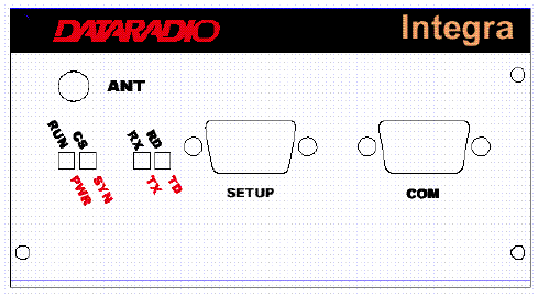
2.2 FRONT PANEL
The various front panel elements are described in the following sections.
Figure 2-1 Integra-TR Front Panel
2.2.1 Antenna Connector
Antenna connector is a female 50-ohm SMA- type. Units operated with a “rubber duck” antenna connected
directly to the antenna connector may exhibit unusual operating characteristics and high levels of reverse
power.
2.2.2 Connection to DTE
Integra-TR is configured as DCE. Most DTE should be connected using a nine-conductor pin-to-pin
“straight” cable. Some RTUs or PLCs may require a special cable to route the signals correctly. See the
documentation for your data equipment for further information.
2-2
Part No. 001-4008-101/102
2.2.3 LED Indicators
Integra-TR has four two-color LED indicators. Their functions are shown in Table 2-1.
* Contact technical support.
2.2.4 COM Port
Baud rates from 300 to 19200 are supported. Integra-TR's are factory set (default) for 9600 b/s, 8 bits, no
parity, and 1 stop bit. Unless required by your operating protocol, we advise restricting port speed to be
equal to or less than the RF network speed.
Table 2-2 COM Port Signals
Table 2-1 LEDs Color Functions
RUN/PWR Green Normal operation
Flash green Sleep mode (flashes during wakeup)
Flash red &
green
Setup mode or loading new application or new bootloader
Flash red Firmware error*
Red CPU or PROM failure*
CS/SYN Off No RF RX carrier
Green Receive carrier present
Red (Reserved)
RX/TX Off No RF RX carrier
Green Receiving network data
Yellow Synthesizer unlocked
Red Transmitter is on
RD/TD Off Idle
Green RX data outgoing from RS-232 port
Red TX data incoming at RS-232 port
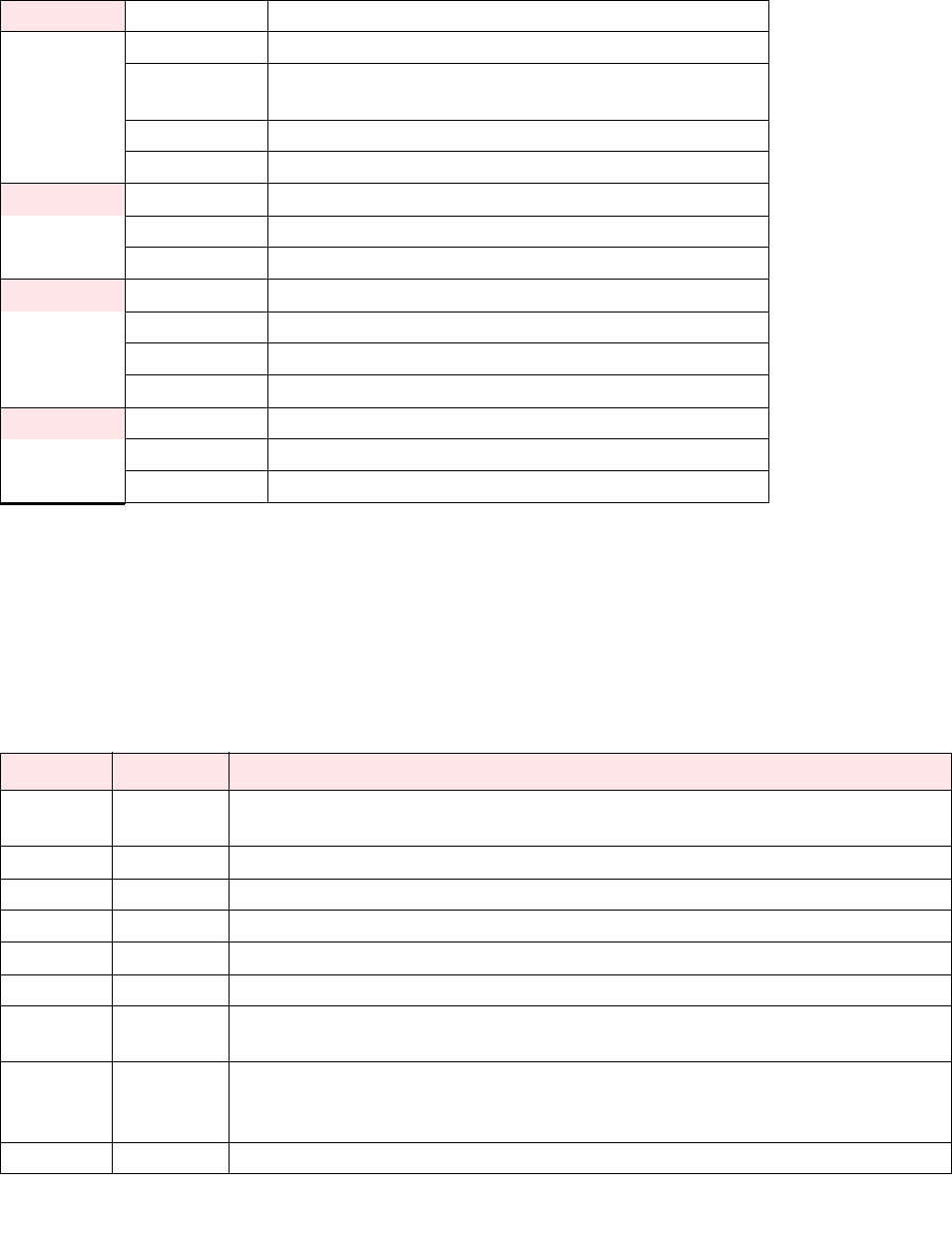
Pin Name Function
1 DCD Output: Always asserted or asserted when receive RF carrier present (selectable via Field
Programming Software)
2 RXD Output: Data from Integra-TR to DTE
3 TXD Input: Data from DTE to Integra-TR
4 DTR Input: Ignored
5 GND Signal and chassis ground
6 DSR Output: always positive
7 RTS Input: Used as a “begin transmission” signal in RTS mode
Will “wake up” unit in sleep mode
8 CTS Output: Used for handshaking in RTS mode and used for flow control in DOX mode
RTS mode: RTS to CTS delay in 4 ms
DOX mode: CTS always asserted except when data overflow is detected
9 RI Not internally connected, reserved
2-3
Part No. 001-4008-101/102
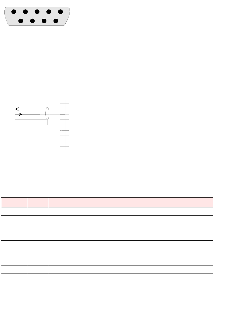
2.2.4.1 Connector Pin Out
The DE-9F pin out is shown in Figure 2.2 for reference.
Figure 2-2 COM and Setup Port Connectors Pin Locations
2.2.4.2 Wire Connection (DOX) Field Programming Software
For DTE that lack RTS control, Integra-TR can operate in DOX mode (Data Operated Transmit) with only
Transmit Data, Receive Data and Ground (“3-wire interface”).
Figure 2-3 3-Wire Interface
2.2.5 Setup Port
The Setup port uses a DE-9 female connector configured as DCE. Signals are described Table 2-4.
Table 2-3 Setup Port Signals
The Setup port uses a proprietary communications protocol designed to work with the Integra-TR Field
Programming Software program. It is also designed to provide numeric diagnostics information when
connected to a PC terminal emulator.
Pin Name Function
1 DCD Tied directly to DTR
2 RXD Data from Integra-TR to setup PC
3 TXD Data from setup PC to Integra-TR
4 DTR Tied directly to DCD
5 GND Signal and chassis ground
6 DSR Output: always positive (asserted)
7 RTS Tied to CTS. Also monitored to “wake up” unit from sleep mode
8CTS Tied to RTS
9 RI Not internally connected, reserved
12345
6789
1
2
3
4
5
6
7
8
9
RXD
TXD
GND
DE-9M

2-4
Part No. 001-4008-101/102
2.3 REAR PANEL
Figure 2-4 Integra-TR rear panel
The various elements are described in the following sections.
2.3.1 Heat Sink
The rear panel heat sink is essential for proper operation of the Integra-TR transmitter. The unit must be
mounted in a location that permits free air circulation past the heat sink. Cooling will be best if the fins are
vertical.
2.3.2 Power
The Integra-TR power requires a regulated power source of 13.3 VDC nominal (10 - 16 VDC max.)
negative ground with a 3.0 A rating. An internal surface-mount 3A fuse (not field-replaceable) and a
crowbar diode protect the main RF power components from reverse polarity. Application of more than 16
VDC will damage the unit and is not covered by the warranty.
WARNING: Do not exceed 16Vdc.
2.3.3 Power / Analog Connector
The 4-pin power / analog connector pin out is shown in Figure 2-5.
Figure 2-5 Analog Connector
Note: The color of the power cable wires are shown in parenthesis. If the analog connections are not used
the green and white wires should be cut back and/or taped to prevent contact. (See Table 1-1 for power
cable part number.)
+13.3 VDC (1) (2) GND
A
nalog 1 (3) (4) Analog 2
/
RX-TP
(red) (black)
(white)
(green)
2-5
Part No. 001-4008-101/102
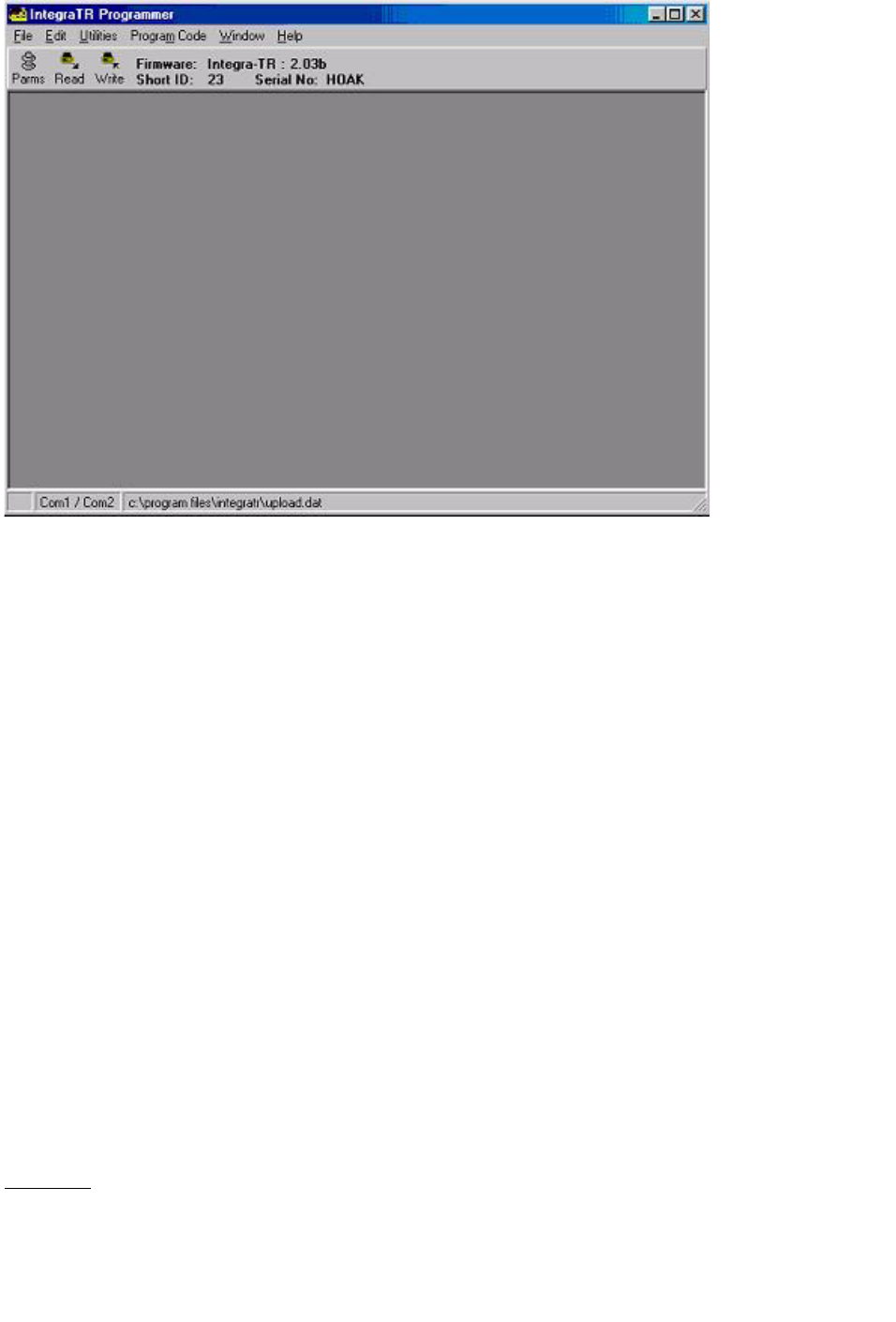
Figure 2-6 Integra-TR Field Programming Software Startup Screen
2.4 INTEGRA-TR FIELD PROGRAMMING SOFTWARE
2.4.1 Introduction
The Integra-TR Field Programming Software is the programming and diagnostics software for the Dataradio
Integra-TR wireless modem. The Field Programming Software allows the user to edit and program user
programmable settings, interactively tune modem and RF parameters, and monitor diagnostic data from the
Integra-TR. See Figure 2-6 for the Integra-TR Field Programming Software startup screen.
This manual assumes the Field Programming Software has been installed on the user’s PC with at least one
operational serial COM Port available.
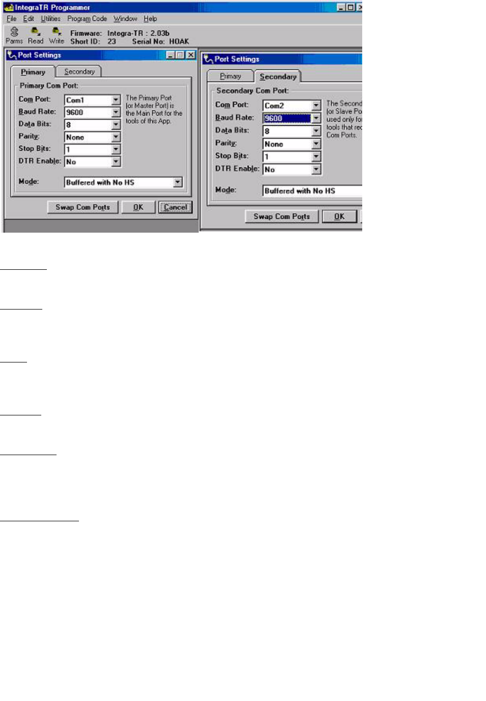
2.4.2 COM Port Settings
Integra-TR programming is done through the PC’s Primary COM Port. Primary and secondary COM ports
are configured with the Field Programming Software. The programming cable (included in the
Programming Kit - DRL part number 250-4008-001) is connected from the Setup Port on the Integra-TR to
the PC’s COM port configured as the Primary Port. The Port Settings screen of the Field Programming
Software is accessed via the Utilities pull-down menu (see Figure 2-7). The Port Settings screens are used to
configure the PC’s serial COM Ports. COM Port parameters are defined in 2.4.2.1. COM Port assignments
are displayed in the bottom status bar of the Integra-TR Field Programming Software screen.
2.4.2.1 COM Port Parameters
COM Port
Selects COM Port number (COM 1-4) for Primary and Secondary COM Ports (see Figure 2-7).
2-6
Part No. 001-4008-101/102
Figure 2-7 Port Settings Screens
Baud Rate
Selects the communication speed for Primary and Secondary COM Ports.
Data Bits
Selects the number of data bits (4-8) transmitted or received for the Primary and Secondary COM Ports.
Parity
Selects transmission or reception of any Parity Bits for the Primary and Secondary COM Ports.
Stop Bits
Selects number of Stop Bits (1 or 2) transmitted or received for the Primary and Secondary COM Ports.
DTR Enable
Used to assert DTR (Data Terminal Ready) line of the RS232 Port when the port is open for the Primary and
Secondary COM Ports.
Swap COM Ports
Selecting the Swap Com Ports button moves the Secondary COM Port settings to the Primary COM Port
(and moves the Primary COM Port to the Secondary settings). Since Integra-TR programming is done
through the Primary COM Port, this is useful when two units are connected to the Primary and Secondary
COM Ports. A Swap COM Ports allows the second unit to be programmed without switching programming
cables.
2.4.2.2
Primary and Secondary Port Settings Communications Modes
The Mode drop down menu configures the communications mode for the Primary and Secondary PC Port.
2-7
Part No. 001-4008-101/102
See Table 2-4 for Communication Modes configurations.
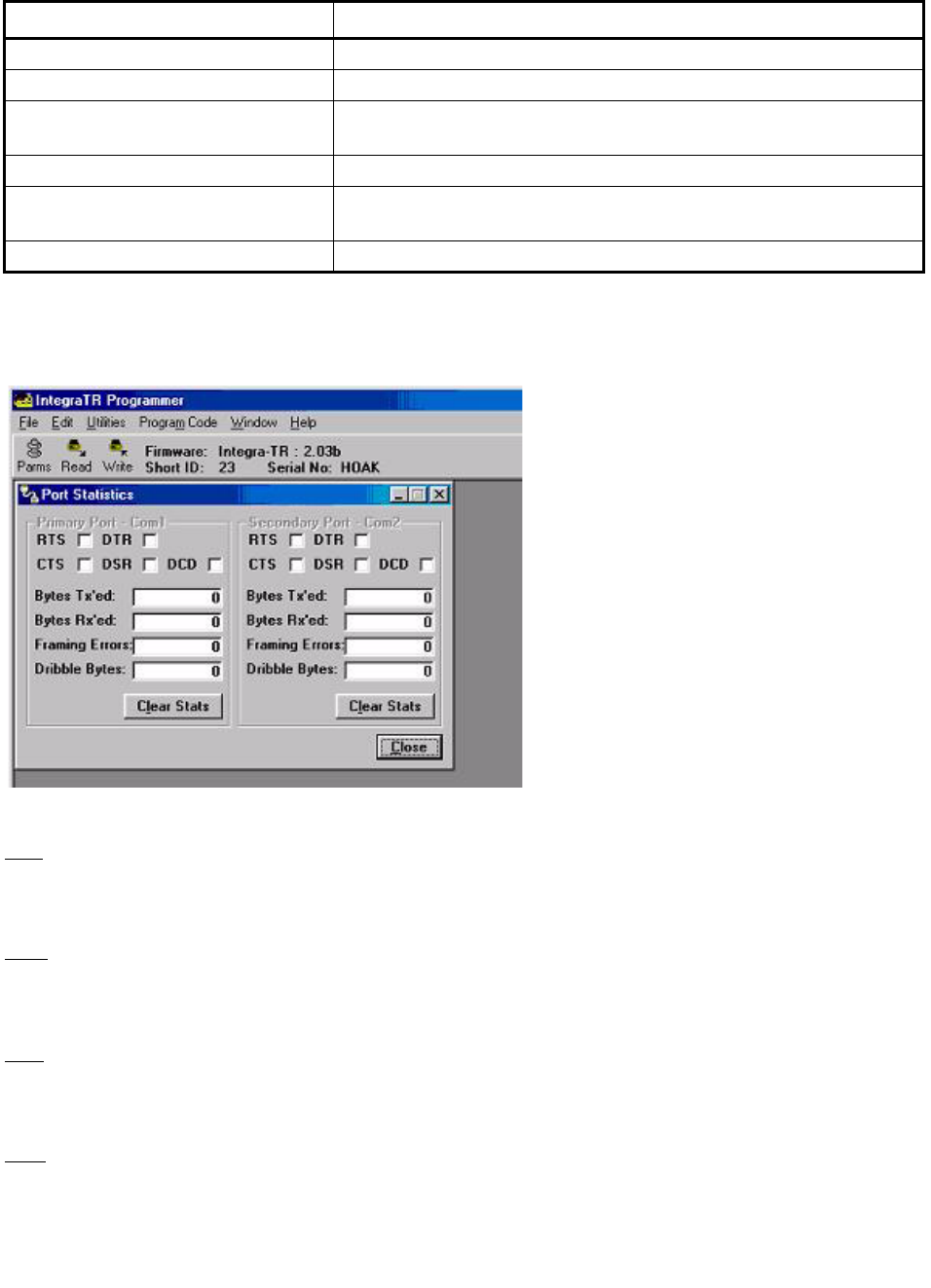
2.4.3 Port Statistics
Port Statistics show current parameters of the PC’s Primary and Secondary COM Ports.
Figure 2-8 Port Statistics Screen
RTS
RTS shows the current state of the RTS (request to send) line. RTS is an output from the PC.
DTR
DTR shows the current state of the DTR (data terminal ready) line. DTR is an output from the PC.
CTS
CTS shows the current state of the CTS (clear to send) line. CTS is an input to the PC.
DSR
DSR shows the current state of the DSR (data set ready) line. DSR is an input to the PC.
Table 2-4 Communication Modes
Mode Description
Sync/ESC with No HS Sends data using Sync/byte-stuffing protocol without handshaking.
Buffered with No HS Sends buffered data without handshaking.
Sync/Esc with RTS/CTS HS Sends data using the Sync/Esc byte-stuffing protocol with RTS/CTS
hardware handshaking.
Buffered with RTS/CTS HS Sends buffered data with RTS/CTS hardware handshaking.
Sync/Esc with Flow Control HS Sends data using the Sync/Esc byte-stuffing protocol with flow control
handshaking.
Buffered with Flow Control HS Sends buffered data with flow control hardware handshaking.
2-8
Part No. 001-4008-101/102
DCD
DCD shows the current state of the DCD (data carrier detect) line. DCD is an input to the PC.
Bytes Tx’ed
Bytes Transmitted shows the number of bytes (characters) transmitted since the port was last opened.
Bytes Rx’ed
Bytes Received shows the number of bytes (characters) received since the port was last opened.
Framing Errors
Framing Errors shows the number of Framing Errors received since the port was last opened.
Dribble Bytes
Dribble Bytes shows the number of extra (not expected) bytes (characters) received since the port was last
opened.
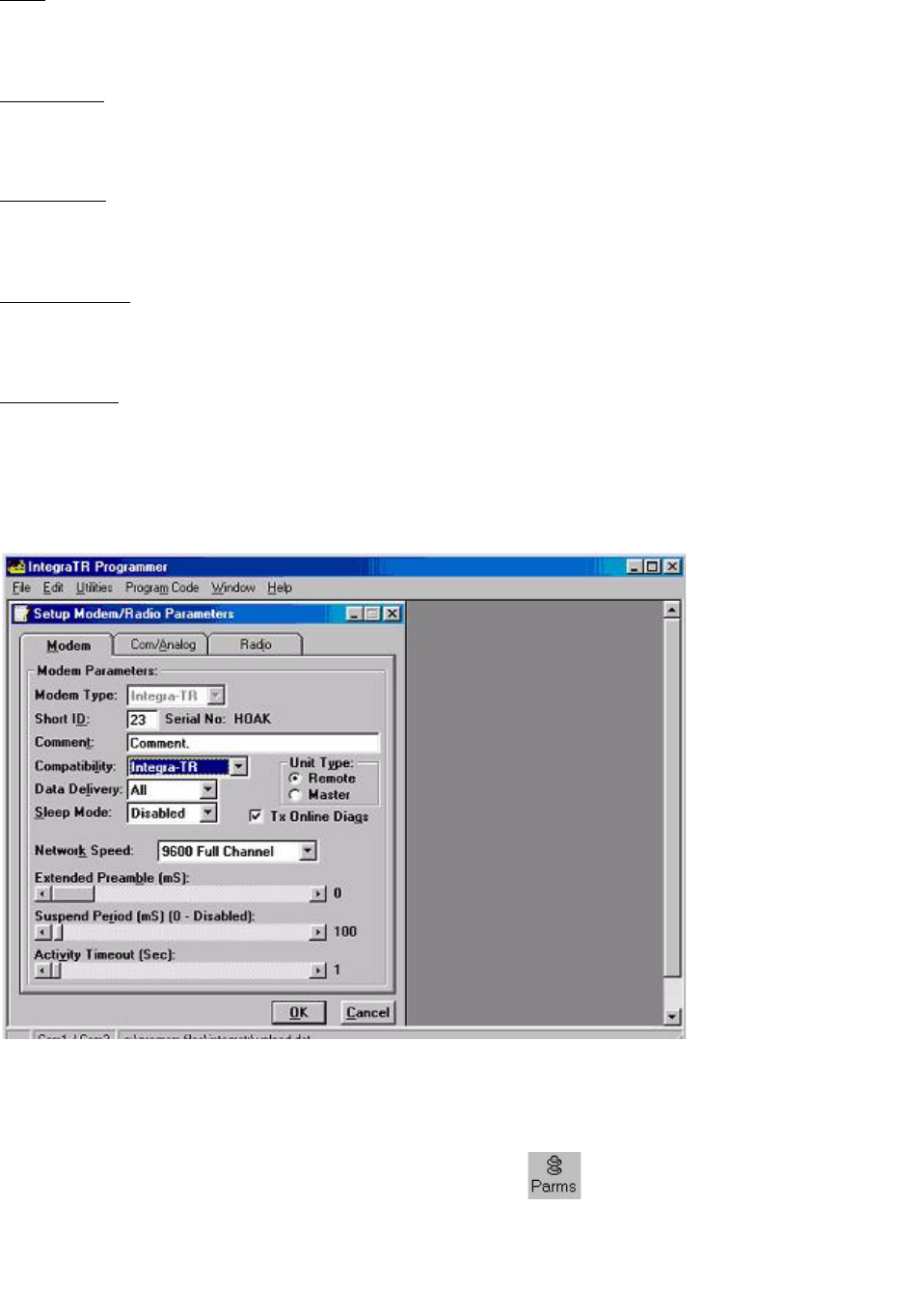
2.4.4 Setup Modem/Radio Parameters
Figure 2-9 Setup Modem/Radio Screen
The Setup Modem/Radio Parameters screen is accessed from the Edit menu pull-down (see Figure 3-1) or
from the Parms icon when the tool bar is visible.

2-9
Part No. 001-4008-101/102
2.4.3.1 Modem Operating Parameters
The Setup Modem/Radio Parameters allows the user to view and edit Integra-TR’s programmable
parameters. Programming parameters can be stored in a data file with the .DAT file extension.
Programmable parameters are used by the Read/Write Parameters screen for programming into nonvolatile
memory.
Parameter settings are modified from three screen tabs: the Modem tab, Com/Analog tab, and Radio tab.
When desired parameters in each tab window have been adjusted, select the OK button to store the
parameter information into local memory and exit the parameter screen. Clicking the Default Parms button
sets certain parameters back to factory default settings. Clicking Cancel exits the parameter screen without
modifying any parameters currently stored in local memory.
Modem operating parameters include:
Short ID
The user-defined number (1 to 254) that identifies an individual unit in a network.
Comment
Integra-TR Field Programming Software supplies this field for user-convenient description(s): customer
name, location. technical info...). Comments can be text up to 24 characters in length, including spaces.
Compatibility
This field selects the compatibility mode (for use with previous versions of Integras).
z
Integra-TR - used for networks made up of Integra-TR modems
z
Integra-T/TR - used for “on-air” backward compatibility with the Integra-T for bit rates of 4800 and 9600
b/s (full channel units only)
The Integra-TR is capable of selectable network speeds of 2400 and 4800 b/s quarter-channel units, 4800
and 9600 b/s for half-channel units, and 4800, 9600, 19200 b/s for full-channel units. Use the Integra-TR
mode whenever feasible.
Data Delivery
This field determines if data should be delivered to the COM port. Designating a unit as Master or Remote
sets a flag in the header identifying the Unit Type of the originating station:
z
All - this option causes the unit to accept (on the receive side) all data transmissions
z
Selective - this option causes the unit to accept (on the receive side) data only if it originates from a unit
of the opposite Unit Type
Sleep Mode
Sleep Mode is one of Integra-TR’s three low power modes of operation (along with “Reduced Transmit
Power” and “Suspend Mode”). When Sleep Mode is enabled, the unit is in low power consumption
(approximately 7 mA). The unit cannot detect the presence of carrier in sleep mode. Asserting RTS on the
COM or Setup Ports wakes the unit. The unit will receive and decode data within 45 to 65 ms (dependent on
model and temperature) after wake-up.

2-10
Part No. 001-4008-101/102
Unit Type
This radio button selects unit type:
z
Remote - Select this option to designate the unit as a Remote station
z
Master - Select this option to designate the unit as a Master station
Designating a unit as Master or Remote sets a flag in the header identifying Unit Type of originating station.
This function is used in conjunction with “Data Delivery” when running certain user protocols.
Tx Online Diags
Transmission of online diagnostics may be enabled or disabled for any unit without affecting its ability to
communicate with other units in a network. At the beginning of each data transmission from a unit,
diagnostics are delivered locally to the units Setup Port regardless of the Tx Online Diags settings. Where
continuous data transmissions are required from a Master unit, diagnostics are sent at 20 second intervals.
Diagnostics information includes:
z
Short ID,
z
Internal case temperature (in Celsius),
z
Battery voltage (in volts),
z
RSSI (in dBm),
z
Forward Power (in watts),
z
Reverse Power Indicator,
z
Remote RSSI
z
Receive quality.
Network Speed
This field selects the network speed (bit rate) of the RF link between units. The can vary from the COM Port
baud rate but must be the same for all units in a network:
z
2400 b/s for one-quarter channel models of Integra-TR
z
4800 b/s - selectable for quarter-, half- and full-channel models of Integra-TR and for full-channel models
of Integra-T
z
9600 b/s - selectable for half- and full-channel models of Integra-TR and for full-channel models of
Integra-T
z
19200 b/s - selectable for full channel models of Integra-TR only
Extended Preamble
This field extends transmitted synchronization time when the unit is used in a network with repeaters. The
default is 0 mS and the range is 0 to 100 mS in 5 mS intervals. Add 5 to 10 mS for each Repeater an
Integra-TR communicates through in a network (dependent on user’s protocol).

2-11
Part No. 001-4008-101/102
Figure 2-9 Suspend Mode Timing Graphic
Suspend Period
This field is used to set the period of time until a unit goes to cycled low power mode - range is 50 to 12,000
mS in 50 mS intervals. Setting to a value of 0 disables Suspend Mode.
Activity Timeout
Activity Timeout is used to set the minimum length of time the unit will remain awake in the presence of a
carrier - range is 1 to 255 seconds in 1 second intervals. This field is active only if Suspend Mode is enabled.
A non-zero value must be set to enable Suspend Mode. The same Activity Timeout and Suspend Period val-
ues must be set for both Master and Remote units. See Figure 2-10 for a Suspend Mode Timing graphic.
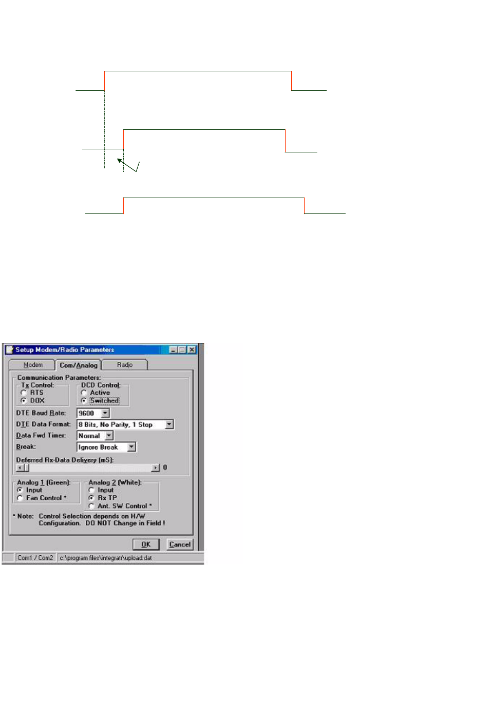
2.4.3.2 Com/Analog Operating Parameters
The Com/Analog tab allows user programming of various COM Port and External input/output parameters
see Figure 2-11).
Tx Control
This radio button selects the unit’s mode at the beginning of a transmission
z
RTS - Request to Send
z
DOX - Data Operated Transmit
Suspend Mode Time Graphic
(not to scale)
100
ms
wake
up
No carrier or
data
Activity
timeout
period
Carrier
sensed, no
data
Suspend mode time
Radio
“on”
Time
Carrier & data -
continues after
Activity Timeout
Integra-TR
Radio samples
carrier `100ms
Radio sees
carrier, no data-
stays “on” for
Activity Timeout
Radio sees carrier &
data- stays on for
multiple Activity Timeouts
until data Rx/Tx is
complete
Radio goes
back into
Suspend
ModeTimer
Note: Graphic uses 100 ms timing parameter as required by Suspend Mode.
2-12
Part No. 001-4008-101/102
Figure 2-10 Transmit Control Signal Timing Graphic
The Transmit Control default mode is DOX in which the unit begins a transmission as soon as data is
presented to the COM Port. The optional mode is RTS in which the unit begins transmission only when the
RS-232 RTS input pin of the COM Port is raised and continues transmitting until the RTS is dropped.
Selecting RTS also activates the switched option in DCD control (see Figure 2-10).
Figure 2-11 Com/Analog Setup Parameters Screen
Integra-TR Control Signal Timing
RTS
(Request to
send)
CTS (Clear
to send
RTS is raised by the PLC/RTU or computer
RTS causes the transmitter to turn on
(Integra) {Synch. Preamble sent)
The PLC/RTU/Computer wants to send data
CTS sent by Integra after delay
4 Ms Fixed
DCD (Data
Carrier Detect)
TX data Data is TX’d (transmitted)
RTS
dropped
after last
character (by
PLC etc)
CTS
dropped
after last
character
is on air
Character in to char out
transit time=37mS Repeater delay=10 preamble

2-13
Part No. 001-4008-101/102
DCD Control
This field selects the mode of the RS-232 DCD (Data Carrier Detect)
z
Active - always asserted
z
Switched - follows the radio carrier and data sent to DTE
DTE Baud Rate
This field selects the port speed of the COM Port (independent of Network Speed)
z
300
z
1200
z
2400
z
4800
z
9600
z
19200
For best results, Dataradio recommends using the same rates for both the COM Port and Network Speeds.
DTE Data Format
This field selects the format for the COM Port. All units in a network must use the same DTE data format:
8 bits, no parity, 1 stop 7 bits, no parity, 1 stop
8 bits, no parity, 2 stop 7 bits, no parity, 2 stop
8 bits, odd parity, 1 stop 7 bits, odd parity, 1 stop
8 bits, odd parity, 2 stop 7 bits, odd parity, 2 stop
8 bits, even parity, 1 stop 7 bits, even parity, 1 stop
8 bits, even parity, 2 stop 7 bits, even parity, 2 stop
Data Fwd Timer
This field selects the timing between data blocks in a transmission to accommodate some RTU’s special
timing requirements:
z
Normal - 15 ms option
z
Fast - 5 mS option (do not use for baud rates below 2400 b/s)
Break
This field selects the unit’s response to break signals on the COM Port:
z
Ignore break - unit does not transmit or receive break signals
z
Transmit break - unit transmits and receives break signals
Deferred Rx-Data Delivery
This field sets the period of time the unit waits until delivering received data to the COM Port. Range is 0 to
255 mS in 1 mS intervals. (Keeps delays minimum for protocols susceptible to inter-character delays.)
2-14
Part No. 001-4008-101/102
Analog 1
Analog 1 selects configuration of Pin 3 of the Power/Analog connector (green wire):
z
Input - for use on units not equipped with the cooling option - can be used to monitor an external voltage
(0 to 10 volts)
z
Fan Control - regulates an external fan. Factory set (enabled) and the default for all units equipped with
the cooling option. The temperature-controlled open-collector transistor is rated for 100 mA max. The
unit’s internal thresholds are set for ON at 48 degrees C and OFF at 38 degrees C. This selection is
dependent on hardware configuration and should not be changed in the field.
Analog 2
This field selects configuration of Pin 4 of the Power/Analog connector (white wire):
z
Input - for use on units not equipped with the cooling option - can be used to monitor an external voltage
(0 to 10 volts)
z
Rx TP - performs as the demodulated signal level test point. The Rx TP level is half of the internal Rx Test
Point.
z
Ant. SW Control - supports the use of a redundant base station. Ant. SW Control configuration is de-
pendent on hardware configuration and should not be changed in the field.
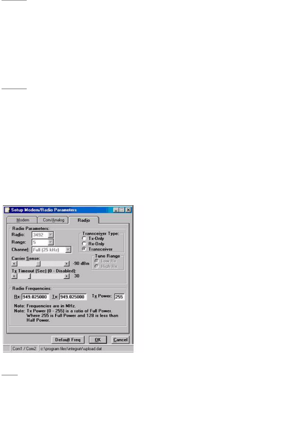
2.4.3.3 Radio Operating Parameters
The Radio tab allows user programming of various radio operating parameters.
Figure 2-12 Radio Setup Parameters Screen
Radio
This field designates the radio model.

2-15
Part No. 001-4008-101/102
Range
This field designates radio frequency range.
Channel
This field specifies whether the unit is quarter-, full-, or half-channel (6.25, 12.5, or 25 kHz).
Transceiver Type
This field configures the transmitting and receiving characteristics of the unit according to network
application:
z
Tx Only - For use in a full-duplex application to disable receptions on the unit used as the transmitter. Tx
Only designation pre-loads the synthesizer and allows faster attack time to speed up transmission response
z
Rx Only - For use in a full-duplex application to disable transmissions on the unit used as the receiver. Rx
Only designation prevents accidental transmissions
z
Transceiver - For use in all other applications
Carrier Sense
Denotes the RSSI level when the unit senses a carrier. Carrier Sense is used for data recovery, in the interpre-
tation of diagnostics, and to turn on the front panel CS LED. The threshold may be raised to prevent false
Carrier Sense operation in the presence of noise, inter-modulation, or other sources of interference (i.e. for
ambient noise at -100 dBm, set the Carrier Sense for -95 dBm).
Tx Timeout
Tx Timeout is used to set maximum period of time the unit will allow in a transmission. The range is 0 to 120
seconds in 1 second intervals (0 being disabled). Tx Timeout is used to protect both the unit and the net-
work in case a transmitter becomes stuck on the air. For Integra-TRs equipped with the cooling option for
extended transmit applications, the Tx Timeout must be disabled.
Rx Frequency
Rx Frequency designates channel pair transmit frequency.
Tx Frequency
Tx Frequency designates channel pair receive frequency
Power
This field designates the channel pair Power Output Adjust value. The default value is 255 (5 watts). This
value should be left at the default value unless lower power is required to meet regulatory requirements or to
increase the allowable transmit duty cycle.
NOTE: Power does not vary linearly with this parameter so some experimentation may be required to
determine the correct power setting.
2-16
Part No. 001-4008-101/102
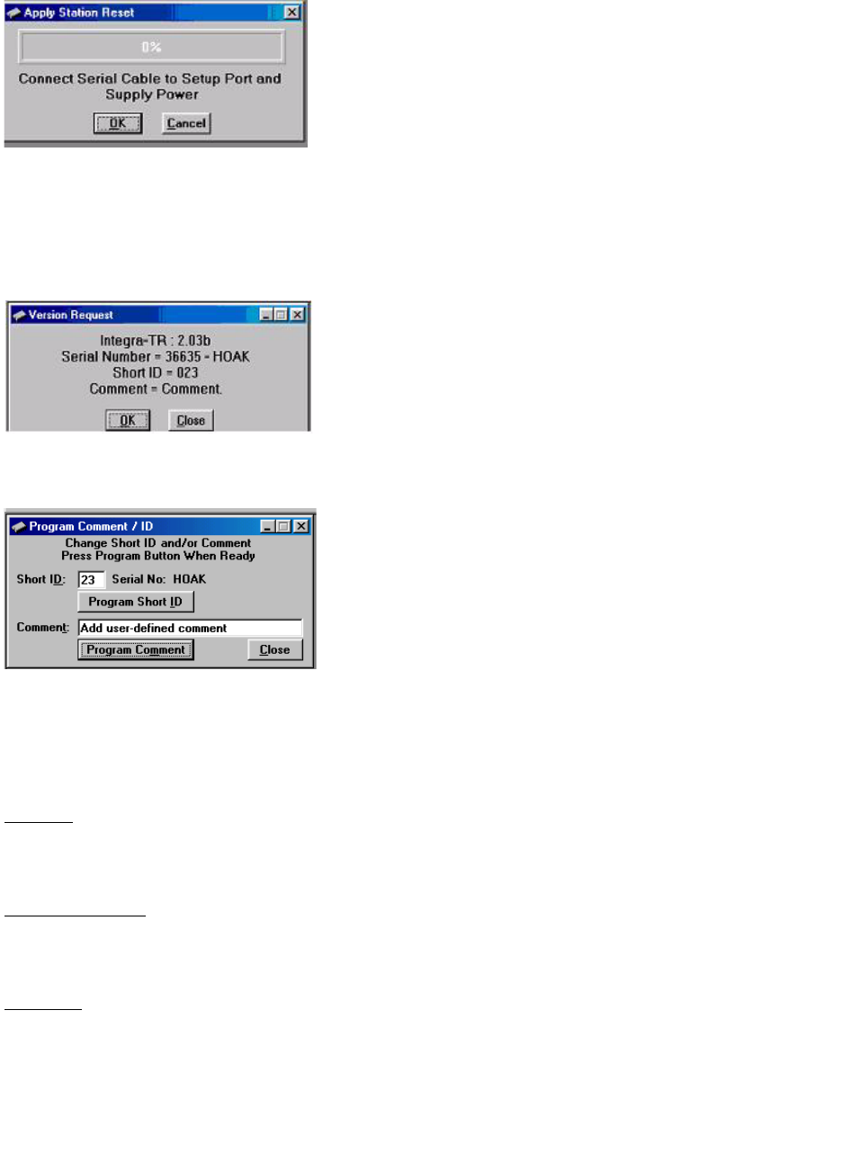
2.4.4 Apply Station Reset
Station Reset tells the Integra-TR to perform a software reset. Performing a Station Reset reacts the same as
cycling power to the unit.
Figure 2-13 Station Reset Screen
2.4.5 Version Request
Selecting Version Request causes the Integra-TR Field Programming Software to display information about
the version of the Integra-TR hardware and firmware.
Figure 2-14 Version Request Screen
2.4.6 Program Comment / ID
Figure 2-15 Program Comment / ID Screen
The Program Comment/ID field allows the user to program a Short ID and/or Comment. This function is
used if the Integra-TR to be programmed was cloned from another unit (See Figure 2-15)
Short ID
The number (1 to 254) that identifies an individual unit in a network.
Program Short ID
Clicking this button programs the new Short ID.
Comment
This field allows the user to give each unit a unique description (s), or add customer name, location,
technical information, or other user desired information. Comments must be text and are limited to 24
characters, including spaces.
2-17
Part No. 001-4008-101/102
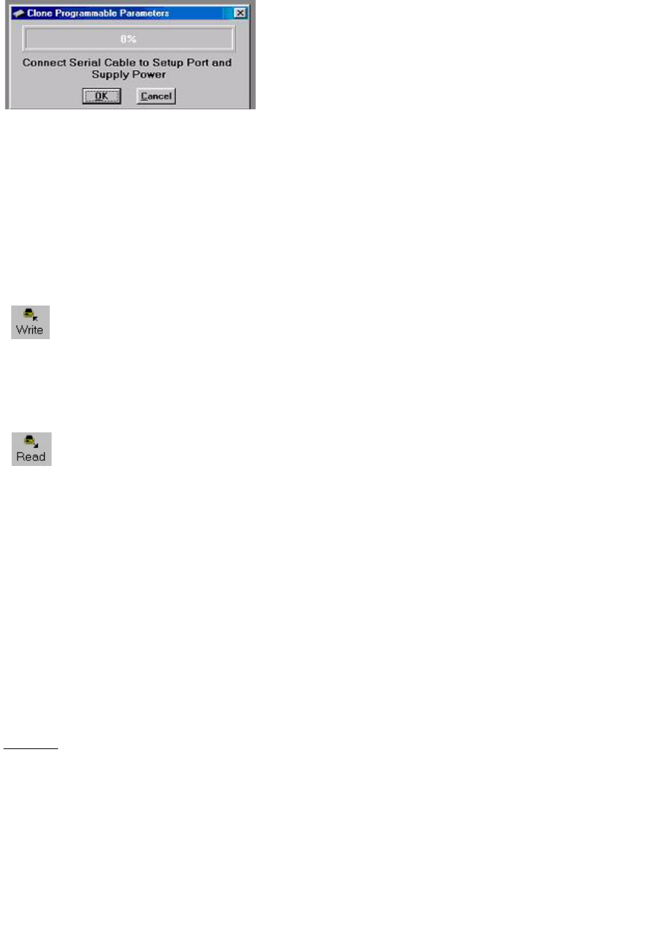
2.4.7 Radio Parameter Cloning
Figure 2-16 Clone Programmable Parameters Screens
After the initial Integra-TR parameters are programmed, saved, and stored in local memory, other Integras in
the system can be quickly programmed using the cloning option under the Edit pull-down menu. Clone
Programmable Parameters will program the radio with all of the currently loaded parameters except the
Short ID and Comment. The cloning option is useful if there is a need to change the DTE Baud Rate for a
number of radios in a system.
2.4.8 Writing / Reading Integra-TR Parameters
After all radio parameters are setup, select the OK button to store the information into the PC’s
memory. To load parameters into the Integra-TR, initiate a Write Programmable Settings from the
Edit menu or select the Write icon from the Tool Bar. After the programmable parameters are
loaded into the Integra-TR, save the parameter information using the Save Data As option in the
File pull-down menu.The name and location of the file (*.dat extension) will appear on the status bar at the
bottom of the screen.
The Read Programmable Settings command will read parameters from the current Integra-TR and
store the information in local memory. The parameters can be viewed and/or edited with the
Setup Modem/Radio Parameters screens.
Note: Dataradio recommends a Read be done anytime an initial connection is made to the Integra-TR Setup
Port before accessing the Setup Modem/Radio Parameters screen. This will help avoid writing erroneous
parameters to the connected unit.
2.4.9 Offline Link Test
The Offline Link Test is used to test the link between two units: the local unit interfaced to the computer and
a remote unit. Blocks of data are transmitted to the remote unit and the remote unit decodes and returns
them. The transmitted and received blocks of data are compared and the ratio of the results are calculated.
NOTE: An Offline Link Test requires suspension of network operation.
An Offline Link Test returns the following statistics (see Figure 2-17):
Local ID
The Local ID is the Short ID of the unit interfaced to the computer.
Remote ID
The Remote ID combo box allows selection of the unit (by choosing it’s Remote ID) from which the Link
Test information is gathered. Remote IDs are set up in the Diagnostic IDs and Alarms Screen.

2-18
Part No. 001-4008-101/102
Figure 2-17 Offline Link Test Screen
Blocks Tx’ed to Remote
Blocks Tx’ed to Remote displays the number of data blocks transmitted to the remote unit.
Responses from Remote
Responses from Remote displays the number of responses heard from the remote unit.
Blocks Rx’ed from Remote
Blocks Rx’ed from Remote displays the number of data blocks received from the remote unit.
Link Quality to Remote
Link Quality to Remote displays the receive quality of the remote unit; the number of correctly decoded
transmissions received by the remote (in the last 15) divided by the number of total transmissions detected
by the remote (in %).
Link Quality from Remote
Link Quality from Remote displays the ratio of data blocks received to data blocks transmitted (in %).
Overall Link Quality
Overall Link Quality displays the overall link quality by combining the Link Quality to Remote ratio with
the Link Quality from Remote ratio (in %).
# of Blocks to Send
# of Blocks to Send allows the user to determine the number of blocks to send before stopping (with 0 being
disabled).

2-19
Part No. 001-4008-101/102
Block Delay (s)
Block Delay (s) allows the user to determine the delay between the transmission of data blocks in 0.25
second intervals (0.00 to 10.00 seconds).
Clear
Clear allows the user to clear the display (blocks transmitted, responses received, blocks received and link
quality).
Start
Start is used to begin the test.
Pause
Pause is used to pause the test and allows the user to resume the test at a later time.
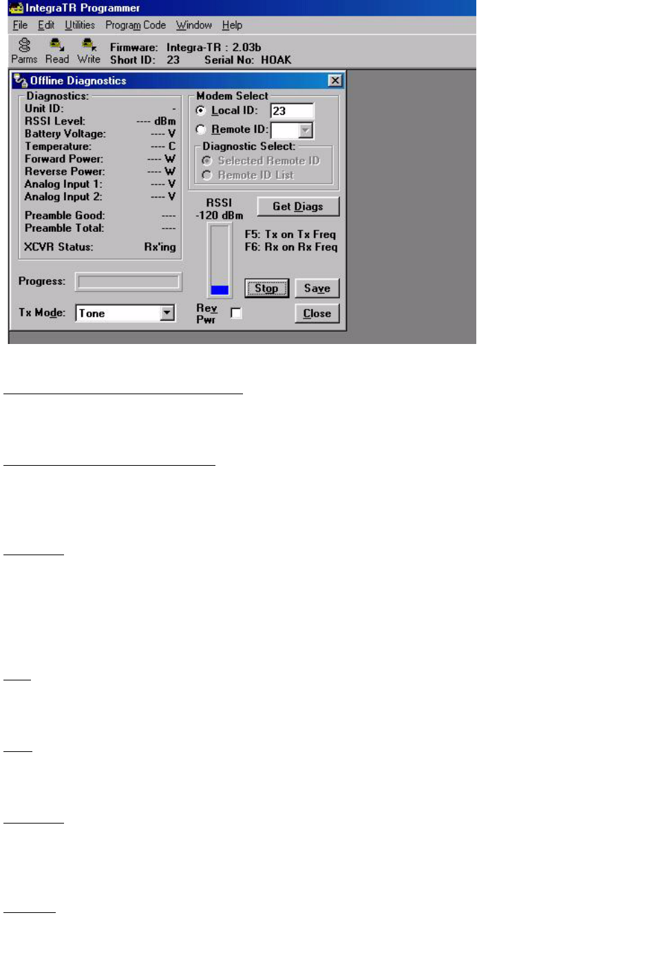
2.4.10 Offline Diagnostics
Offline Diagnostics are returned from a local or remote unit in response to a Get Diags request (see Figure
2-18). An Offline Diagnostics request requires suspension of network operation. Offline Diagnostics
parameters include the following:
z
Unit ID: the Short ID of the unit sending diagnostics
z
RSSI Level: Received Signal Strength Indication (in dBm)
z
Battery Voltage: supply voltage
z
Temperature: internal case temperature (in Celsius)
z
Forward Power: Forward Power (in watts)
z
Reverse Power: Reverse Power (in watts)
z
Analog Input 1: voltage on the External Analog 1 Input from the Power/Analog connector (in volts)
z
Analog Input 2: voltage on the External Analog 2 Input from the Power/Analog connector (in volts)
z
Preamble Good: the number of correctly decoded transmissions received in the last 15. Used with Pream-
ble Total, this serves as an indication of how well the unit is receiving data
z
Preamble Total: the number of total transmissions detected, maximum is 15. Used with Preamble Good,
this serves as an indication of how well the unit is receiving data.
Local ID
The Local ID button allows the user to send commands to the local unit (the unit interfaced to the
computer). The Short ID for this unit is shown.
Remote ID
The Remote ID button allows the user to send commands to any specific remote unit and obtain its
diagnostic information. The Remote ID is selected from the list of Remote IDs set up in the Diagnostic IDs
and Alarms screen.
2-20
Part No. 001-4008-101/102
Figure 2-18 Offline Diagnostics Screen
Diagnostic Select / Selected Remote ID
This button allows the user to gather Offline Diagnostics from the selected Remote ID only.
Diagnostic Select / Remote ID List
This button allows the user to gather Offline Diagnostics from all the IDs in the list of Remote IDs
(including the local unit).
Get Diags
The Get Diags button allows the user to send the command for Offline Diagnostics. The command is sent to
the unit connected to the computer if the Local ID button is selected. The command is sent to the selected
Remote ID if the Remote ID and Selected Remote ID buttons are selected. The command is sent to the list
of Remote IDs if the Remote ID and Remote ID List buttons are selected.
Stop
The Stop button allows the user to stop any commands for Offline Diagnostics from being sent.
Save
The Save button allows the user to save the current Offline Diagnostics to a file.
RSSI/Pwr
The RSSI/Pwr panel shows the current RSSI level (in dBm) while the local unit is receiving and the current
Power Level (in watts) while the local unit is transmitting.
Rev Pwr

2-21
Part No. 001-4008-101/102
The Rev Pwr check box allows the user to view the reverse power instead of forward power while the local
unit is transmitting.
Progress
The Progress panel shows the progress of the Get Diags request.
Tx Mode
The Tx Mode combo box allows the user to select different transmit modes when the unit is told to transmit:
Tone: the unit will transmit a 1200 Hz tone.
Mod Balance: the unit will transmit a 100 Hz square wave.
Random Data: the unit will transmit random data.
No Modulation: the unit will transmit with no modulation.
F5
Pressing the F5 key will cause the unit to transmit on the programmed transmit frequency.
F6
Pressing the F6 key will cause the unit to go to receive on the programmed receive frequency.
Note: Telling a remote unit to transmit will cause the unit to transmit on the programmed transmit frequency
until the Tx Timeout Timer expires. Be sure to program the Tx Timeout Timer in the Setup Modem/Radio
Parameters Screen (see Figure 2-9).
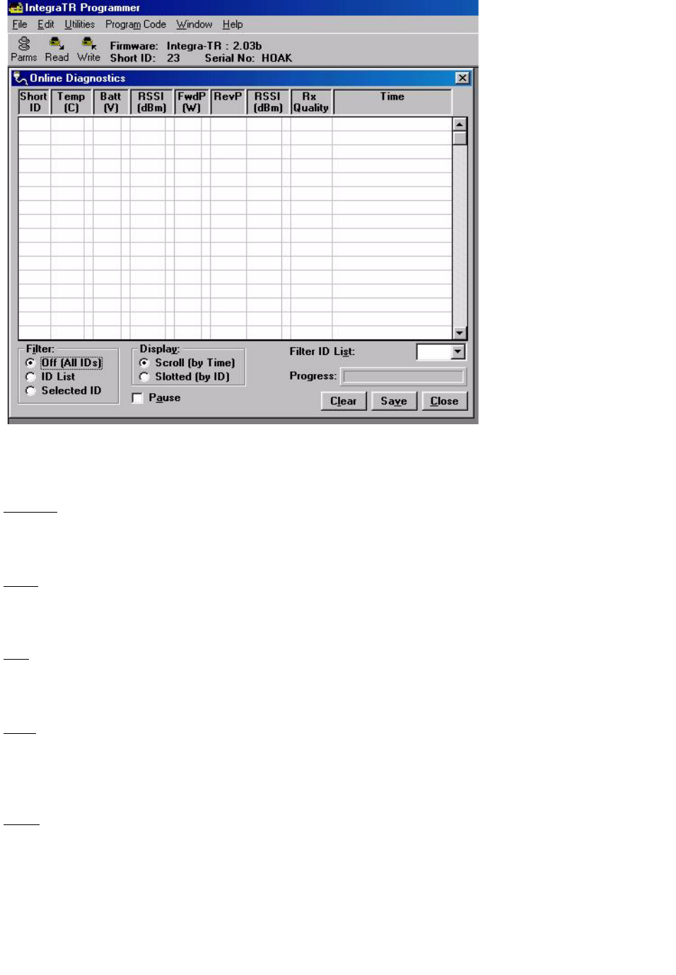
2.4.11 Online Diagnostics
Online Diagnostics are transmitted by each unit in a network before the user’s data is transmitted. All units
must be programmed with the Online Diagnostics parameter found on the Setup Modem/Radio Parameters
screen. The unit that the computer is interfaced with will output Online Diagnostics as they are received.
Using Online Diagnostics does not require suspension of network operation.
Online Diagnostics are subject to alarm conditions defined in the Diagnostic IDs and Alarms screen (see
Figure 2-20). When Online Diagnostics are received and a diagnostic field falls outside the alarm limits, a
“<“ character will designate a value less than the low alarm and a “>” character will designate a value
greater than the high alarm.
2-22
Part No. 001-4008-101/102
Figure 2-19 Online Diagnostics
The following Online Diagnostics are available:
Short ID
The Short ID displays the Short ID of the unit transmitting the diagnostics.
Temp
Temp displays the internal case temperature (in Celsius) of the unit transmitting the diagnostics.
Batt
Batt displays the supply voltage (in volts) of the unit transmitting the diagnostics.
RSSI
RSSI displays the RSSI (in dBm) ID of the unit transmitting the diagnostics. This is the RSSI sampled
during the last transmission the unit received.
FwdP
FwdP displays the forward power (in watts) of the unit transmitting the diagnostics.

2-23
Part No. 001-4008-101/102
RevP
RevP displays the approximate measure of reverse (reflected) power of the unit transmitting the diagnostics.
This is represented as “Good” if the reverse power is within acceptable limits and is represented as “Bad” if
the reverse power is too high.
RSSI
RSSI displays the Remote RSSI (in dBm) of the unit last transmitting the diagnostics. This is the RSSI
found in the Online Diagnostics of the last transmission received by the unit.
Rx Quality
Rx Quality displays the receive quality (in %) of the remote unit. This is the number of correctly decoded
transmissions received (in the last 15) divided by the number of total transmissions detected.
Time
Time is the time stamp when the diagnostics were received.
Filter
Filter allows the user to filter Short IDs. The following options are available:
z
Off (All IDs): no IDs are filtered out
z
ID List: only the IDs in the Filter ID List are shown
z
Selected ID: only the selected ID in the Filter ID List is shown
Display
Display allows the user to format on screen data. The following options are available:
z
Scroll (by time): displays the diagnostics as they are received
z
Slotted (by ID): sorts the diagnostics by Short ID. Using this option, each Short ID will have one row of diagnostics,
showing the most recent
Filter ID List
Filter ID List is a listing of Remote IDs setup in the Diagnostic IDs and Alarms Screen. This list is used for
selecting a filter.
Progress
The Progress panel shows the sorting progress of the diagnostics if a filter was changed.
Pause
The Pause button allows the user to pause the reception of the diagnostics for scrolling through the grid.
Clear
The Clear button allows the user to clear the display and current Online Diagnostics.
2-24
Part No. 001-4008-101/102
Save
The Save button allows the user to save the current Online Diagnostics to a file.
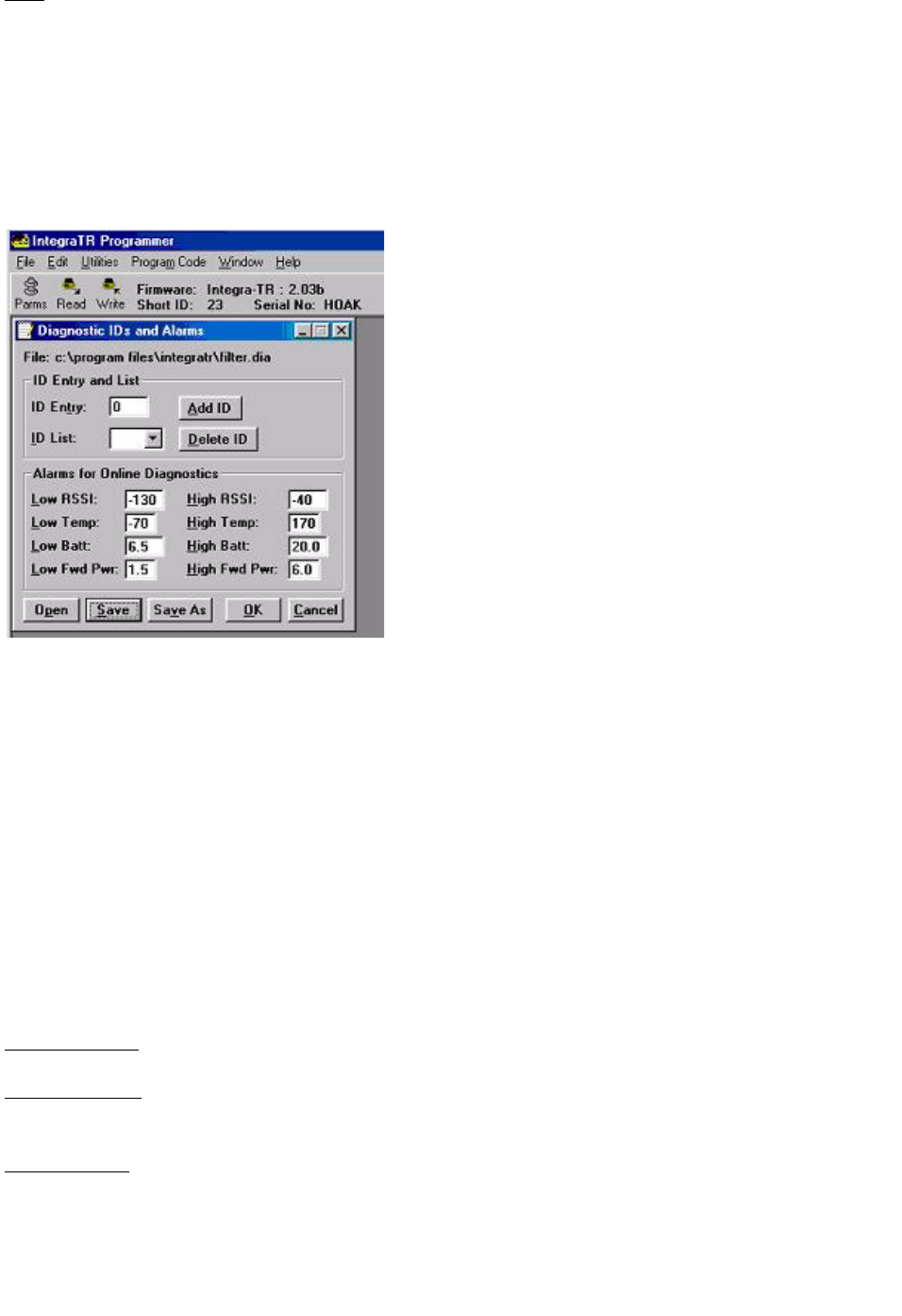
2.4.12 Diagnostic IDs and Alarms
The Diagnostics IDs and Alarms screen allows the user to set up the ID List for use with the Offline Link
Test, and Offline and Online Diagnostics as well as Alarms for use with Online Diagnostics.
Figure 2-20 Diagnostic IDs and Alarms Screen
ID Entry and List
ID Entry: Allows the user to add Short IDs to the ID List. The range of this field is 1 to 255. A Short ID is
added to the ID list by hitting Enter or by pressing the Add ID button.
ID List: Allows the user to select a Short ID from the list to delete. A Short ID is deleted from the list by
pressing the Delete ID button.
Alarms
Alarms are used with Online Diagnostics. When Online Diagnostics are received and a diagnostic field falls
outside the Alarm limits, a “<“ character will designate a value less than the low Alarm and a “>” character
will designate a value greater than the High Alarm.
Low/High RSSI: Low/High RSSI represent the low and high limits for the RSSI diagnostics (in dBm).
Low/High Temp: The Low/High Temp represents the low and high limits for the temperature diagnostics (in
degrees C).
Low/High Batt: Low/High Batt represents the low and high limits for the battery voltage diagnostics (in
volts).
2-25
Part No. 001-4008-101/102
Low/High Fwd Pwr: Low/High Pwr represents the low and high limits for the forward power diagnostics (in
watts).
Open
The Open button allows the user to restore Diagnostic IDs and Alarms from a previously saved file.
Save
The Save button allows the user to save the current Diagnostic IDs and Alarms to the current file.
Save As
The Save As button allows the user to save the current Diagnostic IDs and Alarms to a name different than
the current file.
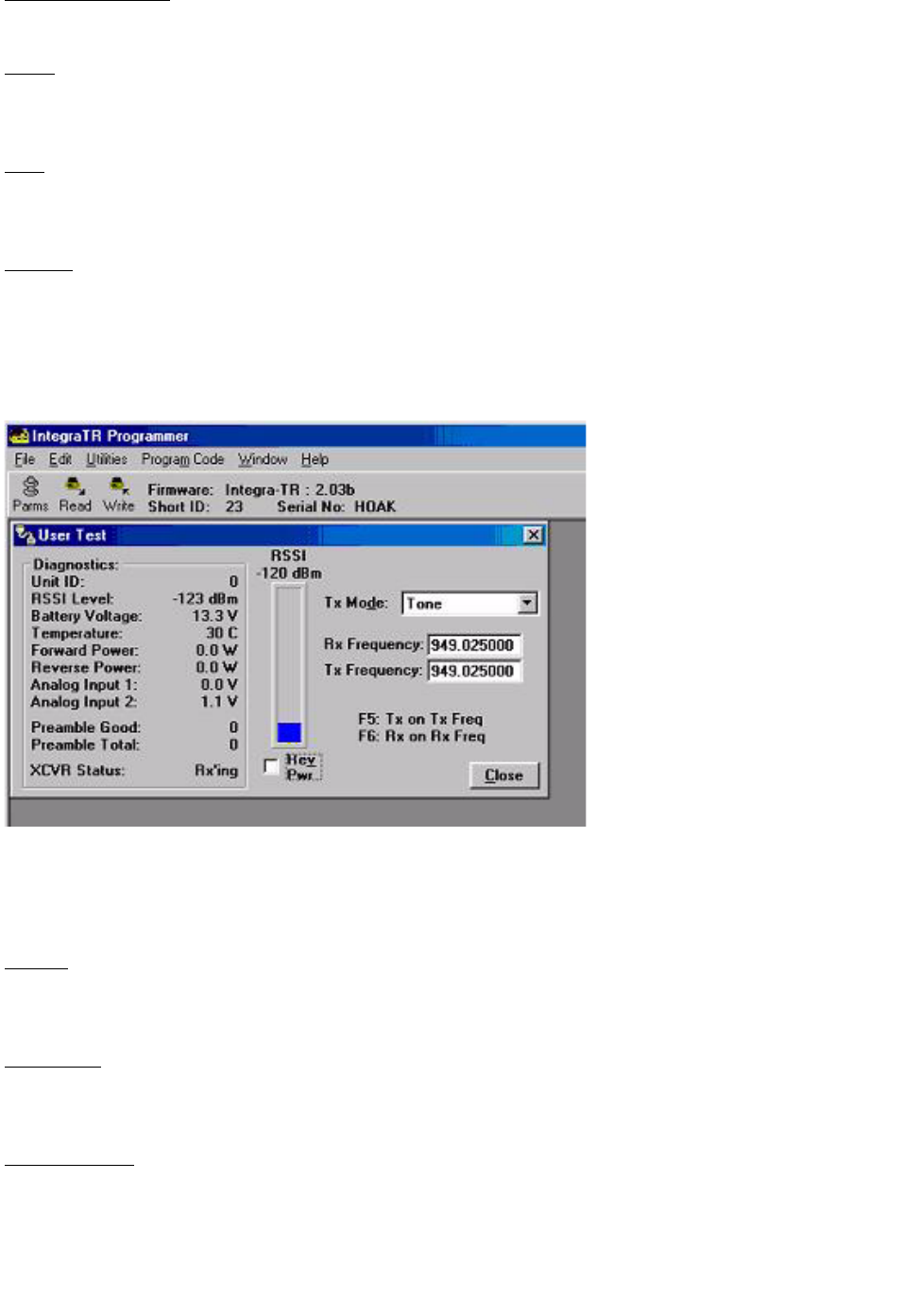
2.4.13 User Test
Figure 2-21 User Test Screen
The User Test utility is an offline function and requires suspension of network operation. A User Test’s
diagnostic parameters include:
Unit ID
The Unit ID is the Short ID of the unit from which the diagnostics were received.
RSSI Level
Received Signal Strength Indication (in dBm)
Battery Voltage
Supply voltage (in volts)

2-26
Part No. 001-4008-101/102
Temperature
Internal temperature (in degrees Celsius)
Forward Power
Forward power (in watts)
Reverse Power
Reverse power (in watts)
Analog Input 1
Voltage on the External Analog 1 Input from the Power / Analog Connector (in volts)
Analog Input 2
Voltage on the External Analog 2 Input from the Power / Analog Connector (in volts)
Preamble Good
The number of correctly decoded transmissions received in the last 15. Used with Preamble Total, this
serves as an indication of how well the unit is receiving data.
Preamble Total
The number of total transmissions detected, maximum is 15. Used with Preamble Good, this serves as an
indication of how well the unit is receiving data.
RSSI /Pwr
This panel shows the current RSSI level (in dBm) while the local unit is receiving and the current power
level (in watts) while the local unit is transmitting.
Rev Pwr
This check box changes forward power to reverse power on the Power Panel from while the local unit is
transmitting.
Tx Mode
This box allows the user to select different transmit modes when the unit is told to transmit.
z
Tone - the unit transmits a 1200 Hz tone
z
Mod Balance - the unit transmits a 100 square wave
z
Random Data - the unit transmits random data
z
No Modulation - the unit transmits with no modulation
2-27
Part No. 001-4008-101/102
Rx / Tx Frequency
Rx / Tx Frequency shows the current transmit frequencies.
F5
Pressing the F5 key will cause the unit to transmit on the programmed transmit frequency.
F6
Pressing the F6 key will cause the unit to go to receive on the programmed receive frequency.
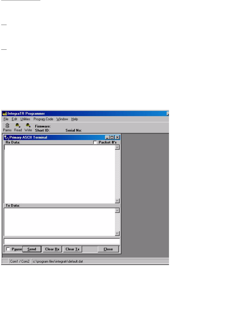
2.4.14 ASCII / Hex Terminal
Terminal Screens allow the user to select an ASCII or Hexadecimal Terminal Screen for the Primary and
Secondary COM Ports (configured in the Port Settings screen - see Section 2.4.3) Data is sent according to
the port configuration set up in the Port Settings screen.
Figure 2-22 ASCII Terminal Screen
2-28
Part No. 001-4008-101/102
2.4.14.1 ASCII Terminal
ASCII Terminal configurations include:
Primary
The Primary ASCII Terminal screen sends and receives ASCII data on the Primary COM Port (set up in the
Port Settings screen).
Secondary
The Secondary ASCII Terminal screen sends and receives ASCII data on the Secondary COM Port (set up
in the Port Settings screen).
2.4.14.2 HEX Terminal
Hex Terminal configurations include:
Primary
The Primary Hex Terminal screen selects a Hexadecimal Terminal screen to send and receive Hexadecimal
data on the Primary COM Port (set up in the Port Settings screen).
Secondary
The Secondary Hex Terminal screen selects a Hexadecimal Terminal screen to send and receive
Hexadecimal data on the Secondary COM Port (set up in the Port Settings screen).
2.4.15 Program Code
The Program Code pull-down menu allows the user to update the Integra-TR firmware (*.bin) with the
Program Firmware option. Select Modem Code File allows the user to select the file to program the
firmware in the Integra-TR.
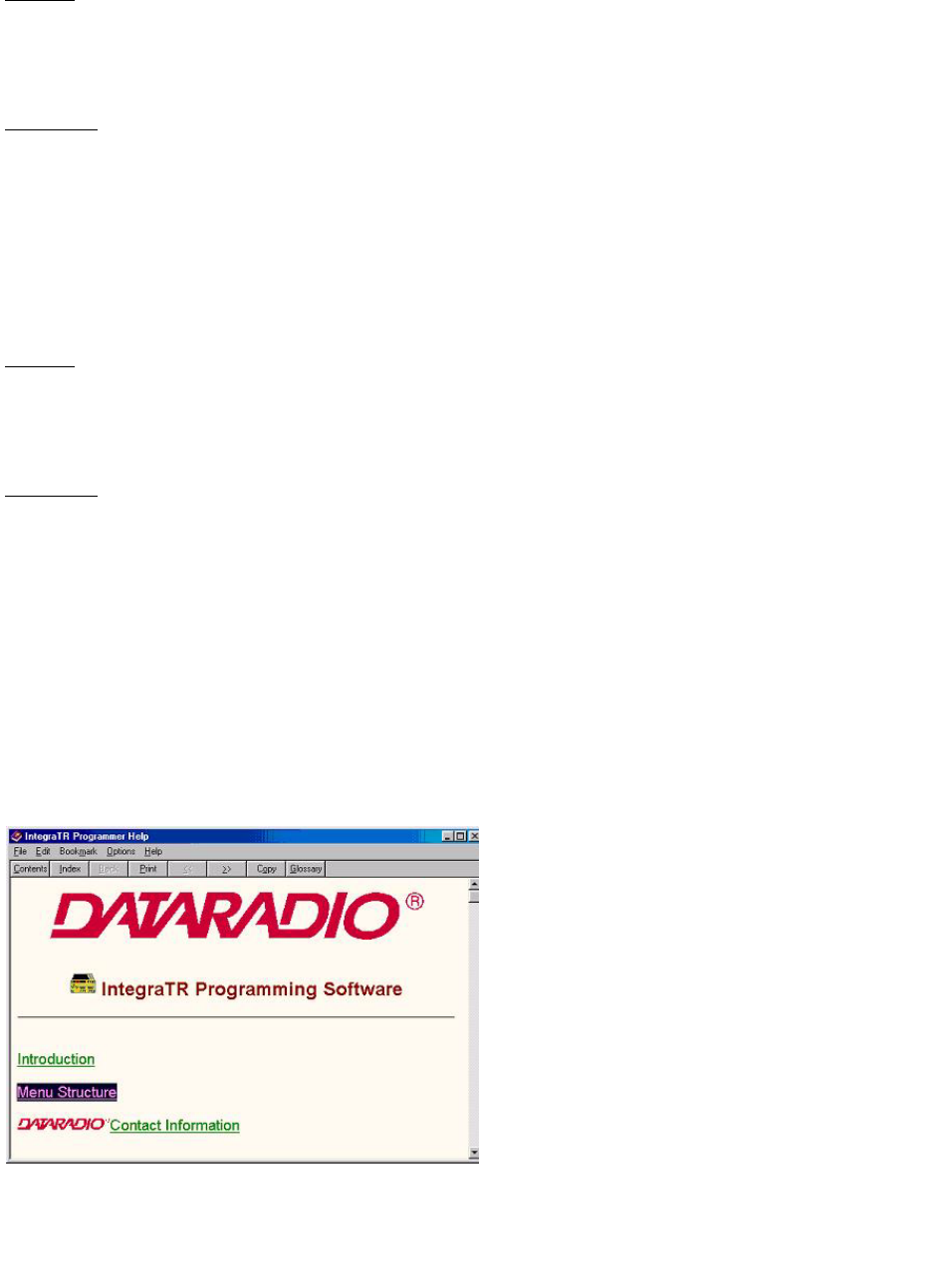
2.5 INTEGRA-TR HELP FILES
Figure 2-23 Integra-TR Online Help Introductory Screen

2-29
Part No. 001-4008-101/102
Integra-TR Field Programming Software’s online help files are accessed by the menu bar at the top of the
Field Programming window.
2.6 OPTIMIZING YOUR SYSTEM
Detailed system engineering is beyond the scope of this manual. However, there are some simple tips that
can be used to optimize performance of a radio based SCADA or telemetry system.
Choose the best protocol Some SCADA devices allow a choice of more than one operating protocol. In
some cases, performance can be improved by selecting a different protocol. Contact Technical Service for
assistance.
Check timer settings Polling protocols issue a poll and wait a certain time for a response. Integra-TR adds a
short amount of delay to each poll and response (typically in the order of 60 to 70 ms). Timer settings that
are too short may cause erroneous indication of missed polls, in which case the application may retry or
continue to cycle, ignoring the missed station. In this case, the response may collide with the next poll,
further increasing errors. Setting an adequate timer margin will avoid problems and maximize performance.
Avoid flow control Set the Com port baud rate to a value less than or equal to the radio network speed (2400,
4800, 9600 or 19200 b/s). In a polling system, this will prevent buffer overflow with possible missed
transmissions. If the port baud rate must be set higher than the radio network speed, you may have to limit
message length to prevent possible buffer overflow. Integra-TR will exert a flow control signal (CTS
dropped) if buffers are almost full, but not all DTE honor such signals.
Use the highest suitable port baud rate (without exceeding the radio network speed) Operating an RTU at
1200 b/s on a 9600 b/s network will increase data transmission delays and reduce system performance.
Evaluate the need for online diagnostics Enabling online diagnostics increases delays by 2.5 to 10 ms
(depending on speed). In critical applications, this extra delay can be eliminated by disabling online
diagnostics. Offline diagnostics (diagnostics on request) remain available.
SECTION 3
MAINTENANCE AND ADJUSTMENTS
3-1
001-4008-101/102
3.1 OVERVIEW AND MAINTENANCE INTERVALS
This chapter outlines the basic tests and adjustments required upon initial installation and thereafter at
annual maintenance intervals or whenever deterioration in performance indicates that adjustment may be
required. Units are delivered from the factory properly aligned and tested on the frequency range specified
at time of order. Adjustment beyond that described in this chapter is not required unless radio modules have
been tampered with or repaired. In such cases, we recommend complete factory re-alignment as special test
equipment is required. This chapter is intended for use by installation and maintenance personnel.
3.2 EQUIPMENT REQUIRED
The adjustments described below require the following equipment:
1. 13.3 VDC / 5A regulated power supply.
2. Radio service monitor (IFR1200 or equiv.).
3. Cable with SMA male connector to connect Integra-TR to the service monitor.
4. Integra Field Programming Software kit.
5. A PC with Windows 95 or later operating system to run the Field Programming Software.
6. Normal radio shop tools.
3.3 TEST POINT
For trouble shooting aid, there is one test point available at pin 4 of the power/analog connector (white
wire). This demodulated signal measurement is half the voltage read at the RSSI bar graph (found in the
Field Programming Software).
Note: the RX-TP mode must be selected (Analog Connector window) using the Integra Field Programming
Software.
3.4 BASIC TESTS / ADJUSTMENTS
Basic tests and adjustments to be performed are:
1. Transmitter power output
2. Transmitter frequency
3. Transmitter deviation
4. Carrier Sense
5. Demodulated signal level
6. 12 dB Sinad
7. Distortion

3-2
Part No. 001-4008-101/102
3.5 PRELIMINARY STEPS
Important Note: Before proceeding make sure that the service monitor has been calibrated recently and has
warmed up for at least the time specified by its manufacturer. Some reported frequency and deviation
problems have actually been erroneous indications from service monitors that have not adequately warmed
up. This is particularly likely when field service is done during winter months.
1. Connect the Integra-TR antenna connector to the radio service monitor RF input using a 023-3410-118 or
equivalent 50-ohm cable. That input should be able to support at least 5 watts.
2. Connect Integra-TR to the power supply and adjust the supply voltage to 13.3 volts.
WARNING: Do not exceed 16 VDC during setting-up for tests and adjustments.
3. Using a 9-conductor straight RS-232 cable, connect the unit's Setup port to the RS-232 port of a PC and
run the Integra Field Programming Software on the PC.
4. Press GET for the unit configuration.
5. From the Settings menu command, click on Radio Settings, set the frequency to be used for testing. Leave
this window open and on top.
6. Follow the steps in Table 7.
3.5.1AFTER ADJUSTMENTS ARE COMPLETED
Adjustments made using the Field Programming Software are temporary and must be made permanent as
follows:
1. After all adjustments are completed satisfactorily, press “PUT” to save the changes permanently
to the unit.
2. Press Station Reset to activate all configuration changes.
WARNING: The frequency band 406 to 406.1 MHz is reserved for use by distress beacons and should not
be programmed into the unit.

3-3
Part No. 001-4008-101/102
1
(Unless you set a lower value). Note that readings less than 5 watts may be due to losses in the cables used for testing. Check
your wattmeter frequency calibration curve.
2
If a psophometrically weighted filter is available on the service monitor, use 0.35
µV
.
Table 3-1 Tests and Adjustments for One-quarter, Half, and Full Channel Units
Step Action Expected Results Measure With If Not?
1 Output Power
5 W
1
+ 10%, -20%
Service
monitor set to
read power
Adjust using the Field Programming Software
Power Out setting (255 is the maximum) or refer
to Factory Tech support
2 Frequency Error
Press TX Unmod
Within + 300 Hz
Service moni-
t o r s e t t o re ad
frequency
Adjust using the Field Programming Software
Freq Warp setting. (Typical adjustment range is
1.5kHz) If found outside limits, call factory
technical support.
3 Deviation
Press TX tone
For any bit rate speeds
selected
Tol. +5%, -10%
For Full channel:
+4.0 kHz
For Half channel:
+2.5 kHz
For One-quarter
channel:
Service monitor
set to read devia-
tion with mid(15-
30 kHz) IF filter
Adjust using the Field Programming Software
Deviation setting (if required)
4 Carrier Sense
Inject a non-modulated
carrier at -120 dBm to the
Integra-TR RF input;
Raise the service monitor RF
output until the CS LED
comes on
The CS LED should be off
The CS LED should come on within 2
dB from the value set by the Field Pro-
gramming Software:
Default: approx. -105 dBm
(-110 in non-refarmed mode)
The threshold may be raised to prevent false
CS operation in the presence of noise,
intermodulation, or other sources of radio
interference (e.g., for ambient noise at -100
dBm (measured with a spectrum analyzer),
set the CS threshold for -95 dBm)
5 Set the service monitor to generate a -80 dBm signal on the selected receive frequency. The signal
should be modulated with a 1.0 kHz tone at deviation specified below.
Set service monitor IF filter to mid (15-30 kHz), no audio filter.
Note: Use test audio (pin 4) of the power/analog connector (white lead) for SINAD and distortion
6 Demodulated Audio
Press CHK
For any bit rate speeds
selected:
For Full channel unit: set
deviation to +4 kHz
For Half channel unit: set
deviation to + 2.5 kHz
For Quarter channel unit:
1 Vpp + 0.1
If read at Test audio pin 4 of PWR
analog connector
Adjust using RXA adjust setting (if required)
7 12 dB SINAD
Set service monitor IF filter to
mid (15-30 kHz)
For Full channel unit: set
deviation to +3 kHz
For Half channel unit: set
deviation to + 1.5 kHz
For Quarter channel
unit:
< 0.5 µV
2
Service monitor
set for SINAD
Refer to Factory Technical Support
8 Distortion
Set service monitor IF filter to
mid (15-30 kHz) Deviation
level as per SINAD above
< 3%
Service monitor
set for
DISTORTION
Refer to Factory Technical Support
SECTION 4
NETWORK TROUBLESHOOTING
4-1
001-4008-101/102
4.1 TROUBLESHOOTING OVERVIEW
The Field Programming Software provides help for the user to find problems on individual units within a
network. This program runs (only) from the Integra Setup port.
Here is a list of tests that a user (having network communication problems) can try while using this
software utility:
With user network application's running:
z
Monitor the current network activity by using online diagnostics monitoring feature
z
Gather diagnostics (i.e. local GET Status) from the unit connected to and check that they are within
tolerances
With user network application offline:
z
Check communication link between two units (i.e. Link test)
z
Gather remote diagnostics (i.e. Remote GET Status) from a “suspect” remote unit and check that they are
within tolerances
z
Check RF signal strength of a particular remote unit transmitting a continuous unmodulated test carrier
(i.e. Remote Carrier button)
z
Check RF power output from the connected unit by using the Carrier test button. The RSSI bar graph will
turn to a divided wattmeter (Forward and Reflected power)
z
Check carrier frequency from the unit connected by using the Carrier button and a RF communication
test set
z
Check transmit deviation from the unit connected by using TX Tone button and a RF communication test
set
4.2 INTDIAG
The Field Programming Software is divided into two distinct parts: the Online and Offline diagnostics.
4.2.1 ONLINE DIAGNOSTICS
Online diagnostics may be used for monitoring an operating network with the user’s applications running.
The diagnostics are piggy-backed (carried along with user data transmissions) and do not interfere with
day-to-day operations. Refer to Table 4-1 for diagnostics, descriptions, and tolerances.
Maintaining a registry listing typical diagnostic readings for a network is an effective tool for comparing
test readings and trend monitoring (system history). Variances in the data displayed can alert technicians to
changes in network status. Earlier detection leads to earlier intervention.

4-2
Part No. 001-4008-101/102
4.2.2 OFFLINE DIAGNOSTICS
Offline diagnostics are used for trouble-shooting and test transmissions to remote units or to a local
connected unit. Offline diagnostics are intrusive as they take control of radio channels. User applications
must be offline.
4.3 GET STATUS
The Get Status function allows the user suspecting network communications problems to gather diagnostics
and check tolerances as follows:
z
Local GET Status: gathers diagnostics from the unit connected to the network
z
Remote GET Status: gathers diagnostics from a suspect remote unit connected to the network
Values displayed are taken at the moment the GET Status button is pressed. The GET Status does not
continuously update. Press the Clear button and press GET Status again to update the information.
Table 4-1 Diagnostic Information
Field Name Description Tolerance
Unit ID Identifies the unit whose diagnostics are displayed Between 1 & 254
FPWR Approximate measure of transmit RF power
If power read from Bar graph or from reported diagnostics
Note: If power read from an external wattmeter
Normally 3.5 to 6.0W
Normally 4.0 to 5.5W
RPWR Approximate measure of reflected power.
Online Diagnostics:
Offline Diagnostics:
0 if reflected power is within
limits, 1 if reflected power is
too high. The threshold is set
to approximately 1/4 of
FPWR
Value is in watts, ideally
close to zero, but values up
to about 15% of FPWR
may be encountered in
properly operating
systems.
If a dummy load is used to
test a unit, expect reflected
power to be less than 0.2W
RSSI
and Remote
RSSI
If “Radio Source” is in “Remote” mode:
z
the RSSI reading indicates local station signal strength in
dBm as heard by the remote
z
the Remote RSSI indicates how well the local unit receives
the remote signal measured in dBm
If “Radio Source” is in “Local” mode:
z
the RSSI reading indicates how well the local unit receives
the remote signal measured in dBm.
z
the Remote RSSI reading indicates local station signal
strength in dBm as heard by the remote
Normally +/- 3dB accuracy A
good received signal level
should be higher than -
90dBm
table continued one 4-3

4-3
Part No. 001-4008-101/102
4.4 OFFLINE LINK TEST
Tests the network data link status by sending a number of transmissions to a remote unit, back from the
remote, computing a ratio of good to bad signals received and displaying the result as a link quality for both
individual links as well as the overall link.
Caution: Shut down your application before pressing “Link Test”.
Before starting a Link Test:
1. Ensure that the Radio Source selected is “Remote”.
2. Click in the active Short ID field and enter the address of the desired remote unit.
3. Press the “Link Test” button to start transmitting blocks of data.
The selected remote decodes and returns data blocks. Transmission will continue until the link test button is
pressed again or after 100 data blocks are transmitted. The sent and received data are compared and the ratio
of good to bad blocks are calculated. The error rate is calculated separately for each direction and for the
link as a whole. The results are displayed on the message screen in the format detailed in Table 4-2.
Temp Internal case temperature Operating limits:
-30 degrees C to
+75 degrees C
SWB+ Selected unit main DC power measured in tenths of a volt
from 6.0 to 18.8 volts, WARNING: Do not exceed 16Vdc.
Application of more than 16 VDC will damage the unit and is
not covered by the warranty.
Should nominally be close to
13.3VDC
Operating limits:
10.0 to 16.0 V
Peak Demodulated signal voltage: peak-to-peak
(Available only for Offline Get Stats)
See transmit deviation tables
Ext1 User-specified “Analog 1" input as a voltage be-tween 0 and
10 volts DC in tenths, at 8 bits of resolution.
(Available only for Offline Get Stats)
If the “Fan Control” (Analog 1) box is checked in the RSS
program, the value displayed will be 00.0 Volt
0 to 10.0 VDC
Ext2 User-specified “Analog 2" input as a voltage be-tween 0 and
10 volts DC in tenths, at 8 bits of resolution.
(Available only for Offline Get Stats)
If the “Rx/Tp (Analog 2) box is checked in the RSS program,
the value displayed will be 00.0 Volt
0 to 10.0 VDC
Good Number of correctly decoded transmissions in the last 15
received
In multiple frequency networks (duplex), this ratio will be an
aggregate of all stations heard. In single frequency networks
(simplex), this ratio usually represents receptions from the
master station.
15/15 equals 100% Lower
values (8/15), coupled with
strong received signals
(Remote RSSI), usually mean
local interference at the
remote site.
Total Used with the number in the field “Good” to establish a
percentage indicative of reception quality.
Field Name Description Tolerance

4-4
Part No. 001-4008-101/102
Table 4-2 Link Test Display Format
4.5 BAR GRAPH
A Received Signal Strength Indicator (RSSI) bar graph is available during continuous test transmissions
(i.e., remote “Tx Tone” and “Carrier”). The appearance of the “Local RSSI” indicator is a single vertical
graph bar with indicated values in “dBm”. The accuracy of the reading is normally better than +/- 3db.
The bar graph changes during user maintenance local test transmissions of “Tx Tone” and “Carrier”. A split
screen of two parallel vertical bars is seen. The “Local TX Pwr” measurements of “Forward power” and
“Reflected power” are in “Watts” (see Figure 4-1).
4.6 CARRIER
To send an unmodulated carrier, press the “Carrier” button. Used mainly to check carrier frequency, RF
power level (local unit) and received signal strength from a remote unit.
Warning: Care must be taken while reading transmit deviation remotely. Over-the-air service monitor
readings may give higher results than expected because of RF noise and interference that superimpose
on the received signal.
z
If Source is “Local”, pressing Carrier transmits until the button is pressed again
z
If Source is “Remote”, the selected unit will send for 30 seconds. Remote transmissions cannot be
interrupted
All buttons are inactive during test transmissions.
4.7 TX TONE
The TX Tone is used mainly to check transmit deviation. To send a modulated carrier, press the “TX Tone”
button (see Figure 4-1).
z
If Source is Local, sends a 1200 Hz sine wave for 30 seconds or until the button is pressed again
z
If Source is Remote, causes the selected ID remote to send a tone for 30 seconds. Remote transmissions
cannot be interrupted. All buttons are inactive during test transmissions. Typical transmit deviation are
network speed dependant and are shown in Table 4-3.
Action Format Results Relation
Blocks Sent 0-100 Records the total number of blocks transmitted to the remote A
Blocks Received by remote 0-100 Indicates recorded total number of blocks received by the remote B
Link Quality to remote 0.0% to
100.0%
Ratio (percentage) of blocks received by the remote compared to
blocks transmitted. Value is indicative of link quality to remote
B over A
Responses from remote 0-100 Indicates recorded total of response-blocks received from the
remote
C
Link Quality from remote 0.0% to
100.0%
Ratio (percentage) of blocks received from the remote compared to
the recorded total of blocks received by the remote. Value is indica-
tive of link quality from remote
C over B
Overall Link Quality 0.0% to
100.0%
Ratio (percentage) of blocks received from the remote compared to
the recorded total of blocks first transmitted to the remote. Value is
indicative of overall link quality to and from remote
C over A
4-5
Part No. 001-4008-101/102
Table 4-3 Typical Transmit Deviation
Connected to an Integra-TR, Full Channel, Part Number 242-40X8-Y30, Native Compatibility Mode
Network Speed
(in b/s)
Typical Deviation
(kHz)
Voltage at Pin 4 when receiving that deviation from other
units (white wire of analog/power connector) (Vpp)
19200 + 4.0 1.5
9600 + 4.0 1.5
4800 + 4.0 1.5
Connected to an Integra-TR, Quarter Channel, Part Number 242-40X8-XXX, Native
Compatibility Mode
Connected to an Integra-TR, Half Channel, Part Number 242-40X8-Y10, Native Compatibility
Mode
9600 + 2.5 1.5
4800 + 2.5 1.5
Connected to an Integra-TR, Full Channel, Part Number 242-40X8-Y30, Integra-T/Integra-TR
Compatibility Mode
9600 + 3.0 1.5
4800 + 3.0 1.5
Connected to an Integra-TR, Quarter Channel, Part Number 242-40X8-XXX, Native
Compatibility Mode
4800
+ .05 1.5
2400
+ 1.64 1.5
Connected to an Integra-T, Full Channel, Part Number 242-40X7-Y30
9600 + 3.0 1.5
4800 + 4.0 1.5

SECTION 5
CONFIGURABLE PARAMETERS
5-1
001-4008-101/102
5.1 PARAMETER OVERVIEW
The parameters used to configure the Integra-TR units are described in the Field Programming Software
help file. Section 5 summarizes the Integra-TR parameter settings and their variations when used within a
network.
Refer to help files for descriptions of the above fields.
Table 5-1 Normal Factory Settings (Units)
Fields Integra-TR with other
Integra-TR Integra-TR with Integra-T Integra T
Network Settings
Compatibility Mode Integra-TR Integra-TR & Integra-T (N/A)
Tx/Rx Mode Both Tx and Rx (N/A)
Extended Preamble (ms) 0
Network Speed 19200 Full Channel,
9600 Half Channel, or
2400 Quarter Channel
9600 Full Channel
Tx Time Out 30 sec ON
Tx Online Diagnostics Yes
Unit Type Master
Data Delivery All
Suspend Period (ms) 0
Activity Time-out (sec) 5
Sleep Mode Disable (N/A)
COM Port
Device Baud 19200 9600
Data fwd timer Normal
Parity 8 bit, no parity, 1 stop bit
Break Ignore break
Xmit Control DOX
DCD Control Active
Analog Connector
Analog 1 Input or Fan Control
(Units with cooling option)
Input
Analog 2 Input
Frequency
Transmit User choice
Receive User choice
Adjustments
Carrier Sense (-dBm) 105 110
Power Out 255 (indicates 5 Watts nominal)
Frequency Warp Grayed out (radio dependent)
Values set at factory can be changed, if required; hit related test button to
enable field
Deviation
RXA Adjust

5-2
Part No. 001-4008-101/102
Table 5-2 Normal Factory Settings (Bases)
Refer to help files for descriptions of the above fields.
Fields Full Duplex Base Integra-TR with
other Integra-TR
Redundant Integra-TR Full Duplex
Base with Integra-TR/ Integra-T
RX Unit TX Unit Rx Units TX Units
Network Settings
Compatibility Mode Integra-TR Integra-TR and Integra-T
Tx/Rx Mode Rx Only Tx Only Rx Only Tx Only
Extended Preamble (ms) 0
Network Speed 19200 Full Channel, 9600 Half Channel,
or 2400 Quarter Channel
9600 Full Channel
Tx Time Out Disable
Tx Online Diagnostics Yes
Unit Type Master
Data Delivery All
Suspend Period (ms) 0
Activity Time-out (sec) 5
Sleep Mode Disable (N/A)
COM Port
Device Baud 19200 9600
Data fwd timer Normal
Parity 8 bit, no parity, 1 stop bit
Break Ignore break
Xmit Control DOX
ActiveDCD Control
Analog Connector
Analog 1 Input Fan Control Input Fan Control
Analog 2 RxTp Input RxTp Ant. SW Control
Frequency
Transmit User Choice
Receive User Choice
Adjustments
Carrier Sense (-dBm) 105 (N/A) 110 (N/A)
Power Out 255 (indicates 5 Watts nominal)
Frequency Warp Grayed out (radio dependant) Values are set at factory; can be changed if required; hit
release test button to enable fieldDeviation
SECTION 6
CIRCUIT DESCRIPTION
6-1
001-4008-101/102
6.1 OVERVIEW
Section 6 describes the circuit operation of the logic board. This section is intended for use by engineering
and service personnel.
6.2 CIRCUIT DESCRIPTION
Refer to Figure 6-1 for the block diagram of the Integra-TR Logic Board.
6.2.1 MICROPROCESSOR CIRCUIT
The microprocessor contains two Z84015 CMOS low power Intelligent Peripheral Controllers (IPC). Each
IPC is an 8-bit microprocessor integrated with CTC, SIO, PIO Clock Generator Controller and Watch Dog
Timer.
One of the Z84015s (U17) is used in the normal mode. The other Z84015 (U21) is used in the evaluation
mode and only the CTC, SIO and PIO sections are used. The CPU section is disabled.
The first Z84015 Clock Generator uses a 19.6608 MHz crystal that provides a CPU clock rate of 9.8304
MHz for both Z84015s. The 9.8304 MHz clock is further divided by 2 to feed all 8 CTC (4 in each Z84015).
The 64K-memory space of the Z84015 is divided into two blocks of 32k each. The lower 32K are used for
the firmware program and the upper 32K by the CMOS RAM (U18). The memory IC used for the program
is a CMOS FLASH (U22) with 1024 sectors of 128 bytes each.
The dual Z84015 circuit provides up to 8 Counter Timer Channels (CTC), 4 Serial Input/Output (SIO) and
32 Parallel In-put/Output (PIO) lines.
The CPU also provides the clock for the CPLD modem.
6.2.2 RS232
The RS232 IC (U15) is used to interface the application DE-9 connector to the SIO_B section of U17, and
the set-up DE-9 connector to the SIO_A section of U21. Two receivers remain enabled in sleep mode to
ensure fast wakeup.
6.2.3 MODEM
The modem section is used to interface the serial digital data to the transceiver.
The CPLD modem IC (U16) with a programmable Raise-Cosine filter (U10) operates in DRCMSK mode at
2400, 4800, 9600, and 19200 bits/sec. It incorporates a 7-bit hardware scrambler and uses Differential
(NRZI) encoding in DRCMSK mode to minimize data pattern-sensitivity. An electronic potentiometer U5B

6-2
Part No. 001-4008-101/102
(E-Pot), controlled by CPU U17, is used to set the transmitter deviation by amplitude adjustment of the
baseband signal. Electronic potentiometer U5C is also provided to fine adjust the RF carrier frequency.
6.2.4 TRANSMIT & RECEIVE DATA
Transmit Data from the RS-232 port is level-shifted to TTL by U15 and passed through the CPU for further
processing and conversion from asynchronous to synchronous format. The CPLD modem, U16, takes the
digital data stream from SIO-A of the CPU and synthesizes to the constant-amplitude analog baseband
signal. The synthesized data stream is filtered by U10, buffered by U9B, and applied to radio module TXA
at P1-6.
Received signals are applied to the RXA pin on P1-13 and amplified by U3A. U3A gain is set by the
electronic potentiometer, U5D, and filtered by U10. The same filter circuit is used for transmission and
reception. Two analog multiplexer/demultiplexer gates (U8A and B) controlled by TX_EN line are used for
sharing. The filter U10 cut-off frequency is programmable by the CPLD, based on the data rate. The analog
signal is buffered by U1D and fed to Peak Detectors U3C, U3D, and U3B, and to slicer circuit U1C via
U1B. The raw data is passed to the CPLD modem (U16) for de-scrambling and receive clock recovery. The
resulting synchronous bit stream is fed to CPU SIO-A for further processing and conversion to
asynchronous format before delivery to the RS-232 driver and to the user port.
6.2.5 INTEGRA-TR A/D AND DIGIPOT
An 8 channel, 8-bit successive approximation A/D converter, type ADC0838 (U4), is interfaced to CPU
(U17) and Peripheral (U21).
CH0 and CH1 are connected to the positive and negative peak detector of the modem section. The software
can read the positive or negative value of an RX signal, or using the differential mode, the actual peak-to-
peak RX signal value.
CH3 is used to measure the radio RSSI signal which was amplified by U7A.
CH4 is connected to the radio diagnostic signal (P3-14). This pin is used to output an analog signal
corresponding to the power output and the reflected signal.
CH5 is connected to U6 (LM50), a temperature sensor with a -40 to +125°C range.
CH6 is used to read the SWB+ voltage after proper scaling into the 0-5 V range.
CH7 and CH8 are connected to EXT SIGNAL 1 and 2. A 2:1 divider and protection circuit is inserted
between both external signals and the A/D.
The External Signal (pins 1 and 2) is also connected to U21 at PB6 and PB7 through transistors Q3 and Q4
and can be used for Analog Input or Digital Output.
EXT_SIGNAL 2 is also connected to the Rx test point RX-TP through U8A (74HC4066). Under software
control, the RX-TP (scaled down by 2) is available on the power connector for trouble-shooting purposes.
A 4-channel digital potentiometer type (U5) is used to adjust the RX Signal, TX Modulation, Carrier
Frequency and Carrier Detect Threshold.

6-3
Part No. 001-4008-101/102
An 8 channel, 8-bit successive approximation A/D converter, type AD0838 (U9), is interfaced to CPU
(U18) and Peripheral (U20).
U19 generates a power-on reset for the CPU and U6 is a temperature sensor used by the firmware to
compensate for variations in RSSI.
The RSSI signal from the transceiver is amplified and filtered by U7A. The signal is compared to a
threshold value set by digital potentiometer (U5A). The output of the comparator (U7B) is used to change
the hold time of both peak detectors at the beginning of the receive packet.
6.2.6 WAKE-UP CIRCUIT
The wake-up circuit for the Integra-TR consists of a 50 ms monostable circuit that is triggered by the rising
edge of a Sleep signal from CPU (U17). The falling edge of this 50 ms pulse (end of pulse) is connected to
the NMI of the CPU and will wake up the CPU from Sleep mode after 50 ms.
When exiting SLEEP mode on a \NMI, the CPU firmware will increment a counter, then return to Sleep
until it reaches a limit set by a software parameter. When the programmed count is reached the CPU will
wake up the radio and the RS232 driver, program the synthesizer, and watch for channel activity.
While in sleep mode (during the 50 ms pulse), an active RTS from either communication port will reset
(terminate) the 50 ms pulse so that its falling edge will restart the CPU immediately.
The CPU will check to see if either RTS signal is valid each time it is restarted by the \NMI. The firmware
will only start the sleep timer after checking that all “wakeup” inputs are inactive.
6.2.7 POWER SUPPLY
The 13.3-volt DC power input is protected by a 3-amp fuse and reverse-protected by a diode.
A 5 volt, low voltage regulator (U12) is used to power all digital functions and another 5 volt, low voltage
regulator is used to control the analog +5V_SW voltage in the sleep mode.

6-4
Part No. 001-4008-101/102
Figure 6-1 Logic Board Block Diagram
BI-COLO
R
LED
RS-232
DRIVE
R
DE9
DE9
SETUP
PORT
USER
PORT
U15
U21
PERIPHERAL
PA0-PA7
SIO-A
Q3
Q4
OUT
OUT-2
U17
CPU
MEM.
DECODE
U20A,B
ROM
U22
RAM
U18
A
/D
U4
CONTROL BUS
DATA BUS
ADDRESS BUS
CLK,DATA
SELECT
SIO-B
U16
TXC
TXD
CLOCK
RXC
CPLD
MODEM
RXD
MODE
SPEED
RADIO
MODULE
TXA
FILTER
CLOCK
RXS
SLICER
LEVEL
RX-EN
U1B
U5D
E-POT
U3A
RX GAIN
RXA
U5C
E-POT
U9D
WARP
U5B
E-POT
U9B
DEV
U5A
E-POT
U7B
TXA
U8A
U10
U8B
RSSI
U1A
U1D PEAK
DETECT
U3C,D,B
U1C
FAST PEAK DETECT
TX-EN
TX ENABLE
RX-EN
RX ENABLE
SYNTH
SYNTHESIZER ENABLE-CLOCK-DATA
RESET
U19
X
1
19.6MHz
CD
CARRIER DETECT
EXT 1
EXT 2
DIAG
U7A
TEMPERATURE
U6
SENSOR
5 VOLTS
U11,U12
REGULATOR SWB+
13.6 V
OUT
F1
REV DESCRIPTION DATE
DATARADIO INC.
Check
Draft
Design P/N
SIZE
B
SHEET
Check
DOC/N
DATE
LEVEL
INTEGRA-R
LOGIC BLOCK DIAGRAM
210-03315-000
1 / 1
990302
990302
DUNG NGUYEN
EMISSION
0
SECTION 6
CIRCUIT DESCRIPTION
6-1
001-4008-101/102
6.1 OVERVIEW
Section 6 describes the circuit operation of the logic board. This section is intended for use by engineering
and service personnel.
6.2 CIRCUIT DESCRIPTION
Refer to Figure 6-1 for the block diagram of the Integra-TR Logic Board.
6.2.1 MICROPROCESSOR CIRCUIT
The microprocessor contains two Z84015 CMOS low power Intelligent Peripheral Controllers (IPC). Each
IPC is an 8-bit microprocessor integrated with CTC, SIO, PIO Clock Generator Controller and Watch Dog
Timer.
One of the Z84015s (U17) is used in the normal mode. The other Z84015 (U21) is used in the evaluation
mode and only the CTC, SIO and PIO sections are used. The CPU section is disabled.
The first Z84015 Clock Generator uses a 19.6608 MHz crystal that provides a CPU clock rate of 9.8304
MHz for both Z84015s. The 9.8304 MHz clock is further divided by 2 to feed all 8 CTC (4 in each Z84015).
The 64K-memory space of the Z84015 is divided into two blocks of 32k each. The lower 32K are used for
the firmware program and the upper 32K by the CMOS RAM (U18). The memory IC used for the program
is a CMOS FLASH (U22) with 1024 sectors of 128 bytes each.
The dual Z84015 circuit provides up to 8 Counter Timer Channels (CTC), 4 Serial Input/Output (SIO) and
32 Parallel In-put/Output (PIO) lines.
The CPU also provides the clock for the CPLD modem.
6.2.2 RS232
The RS232 IC (U15) is used to interface the application DE-9 connector to the SIO_B section of U17, and
the set-up DE-9 connector to the SIO_A section of U21. Two receivers remain enabled in sleep mode to
ensure fast wakeup.
6.2.3 MODEM
The modem section is used to interface the serial digital data to the transceiver.
The CPLD modem IC (U16) with a programmable Raise-Cosine filter (U10) operates in DRCMSK mode at
2400, 4800, 9600, and 19200 bits/sec. It incorporates a 7-bit hardware scrambler and uses Differential
(NRZI) encoding in DRCMSK mode to minimize data pattern-sensitivity. An electronic potentiometer U5B

6-2
Part No. 001-4008-101/102
(E-Pot), controlled by CPU U17, is used to set the transmitter deviation by amplitude adjustment of the
baseband signal. Electronic potentiometer U5C is also provided to fine adjust the RF carrier frequency.
6.2.4 TRANSMIT & RECEIVE DATA
Transmit Data from the RS-232 port is level-shifted to TTL by U15 and passed through the CPU for further
processing and conversion from asynchronous to synchronous format. The CPLD modem, U16, takes the
digital data stream from SIO-A of the CPU and synthesizes to the constant-amplitude analog baseband
signal. The synthesized data stream is filtered by U10, buffered by U9B, and applied to radio module TXA
at P1-6.
Received signals are applied to the RXA pin on P1-13 and amplified by U3A. U3A gain is set by the
electronic potentiometer, U5D, and filtered by U10. The same filter circuit is used for transmission and
reception. Two analog multiplexer/demultiplexer gates (U8A and B) controlled by TX_EN line are used for
sharing. The filter U10 cut-off frequency is programmable by the CPLD, based on the data rate. The analog
signal is buffered by U1D and fed to Peak Detectors U3C, U3D, and U3B, and to slicer circuit U1C via
U1B. The raw data is passed to the CPLD modem (U16) for de-scrambling and receive clock recovery. The
resulting synchronous bit stream is fed to CPU SIO-A for further processing and conversion to
asynchronous format before delivery to the RS-232 driver and to the user port.
6.2.5 INTEGRA-TR A/D AND DIGIPOT
An 8 channel, 8-bit successive approximation A/D converter, type ADC0838 (U4), is interfaced to CPU
(U17) and Peripheral (U21).
CH0 and CH1 are connected to the positive and negative peak detector of the modem section. The software
can read the positive or negative value of an RX signal, or using the differential mode, the actual peak-to-
peak RX signal value.
CH3 is used to measure the radio RSSI signal which was amplified by U7A.
CH4 is connected to the radio diagnostic signal (P3-14). This pin is used to output an analog signal
corresponding to the power output and the reflected signal.
CH5 is connected to U6 (LM50), a temperature sensor with a -40 to +125°C range.
CH6 is used to read the SWB+ voltage after proper scaling into the 0-5 V range.
CH7 and CH8 are connected to EXT SIGNAL 1 and 2. A 2:1 divider and protection circuit is inserted
between both external signals and the A/D.
The External Signal (pins 1 and 2) is also connected to U21 at PB6 and PB7 through transistors Q3 and Q4
and can be used for Analog Input or Digital Output.
EXT_SIGNAL 2 is also connected to the Rx test point RX-TP through U8A (74HC4066). Under software
control, the RX-TP (scaled down by 2) is available on the power connector for trouble-shooting purposes.
A 4-channel digital potentiometer type (U5) is used to adjust the RX Signal, TX Modulation, Carrier
Frequency and Carrier Detect Threshold.

6-3
Part No. 001-4008-101/102
An 8 channel, 8-bit successive approximation A/D converter, type AD0838 (U9), is interfaced to CPU
(U18) and Peripheral (U20).
U19 generates a power-on reset for the CPU and U6 is a temperature sensor used by the firmware to
compensate for variations in RSSI.
The RSSI signal from the transceiver is amplified and filtered by U7A. The signal is compared to a
threshold value set by digital potentiometer (U5A). The output of the comparator (U7B) is used to change
the hold time of both peak detectors at the beginning of the receive packet.
6.2.6 WAKE-UP CIRCUIT
The wake-up circuit for the Integra-TR consists of a 50 ms monostable circuit that is triggered by the rising
edge of a Sleep signal from CPU (U17). The falling edge of this 50 ms pulse (end of pulse) is connected to
the NMI of the CPU and will wake up the CPU from Sleep mode after 50 ms.
When exiting SLEEP mode on a \NMI, the CPU firmware will increment a counter, then return to Sleep
until it reaches a limit set by a software parameter. When the programmed count is reached the CPU will
wake up the radio and the RS232 driver, program the synthesizer, and watch for channel activity.
While in sleep mode (during the 50 ms pulse), an active RTS from either communication port will reset
(terminate) the 50 ms pulse so that its falling edge will restart the CPU immediately.
The CPU will check to see if either RTS signal is valid each time it is restarted by the \NMI. The firmware
will only start the sleep timer after checking that all “wakeup” inputs are inactive.
6.2.7 POWER SUPPLY
The 13.3-volt DC power input is protected by a 3-amp fuse and reverse-protected by a diode.
A 5 volt, low voltage regulator (U12) is used to power all digital functions and another 5 volt, low voltage
regulator is used to control the analog +5V_SW voltage in the sleep mode.
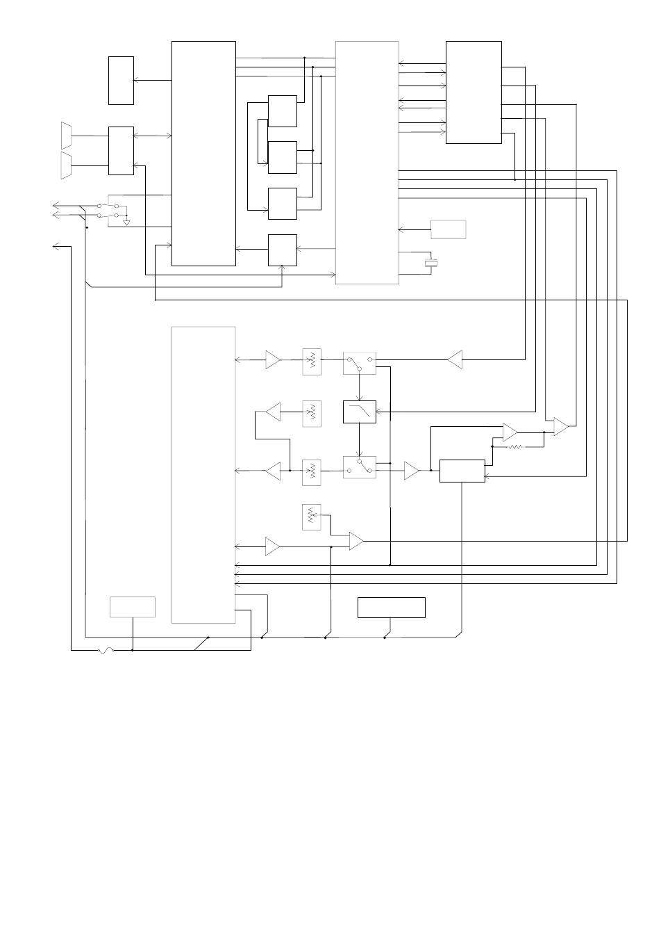
6-4
Part No. 001-4008-101/102
Figure 6-1 Logic Board Block Diagram
BI-COLO
R
LED
RS-232
DRIVE
R
DE9
DE9
SETUP
PORT
USER
PORT
U15
U21
PERIPHERAL
PA0-PA7
SIO-A
Q3
Q4
OUT
OUT-2
U17
CPU
MEM.
DECODE
U20A,B
ROM
U22
RAM
U18
A
/D
U4
CONTROL BUS
DATA BUS
ADDRESS BUS
CLK,DATA
SELECT
SIO-B
U16
TXC
TXD
CLOCK
RXC
CPLD
MODEM
RXD
MODE
SPEED
RADIO
MODULE
TXA
FILTER
CLOCK
RXS
SLICER
LEVEL
RX-EN
U1B
U5D
E-POT
U3A
RX GAIN
RXA
U5C
E-POT
U9D
WARP
U5B
E-POT
U9B
DEV
U5A
E-POT
U7B
TXA
U8A
U10
U8B
RSSI
U1A
U1D PEAK
DETECT
U3C,D,B
U1C
FAST PEAK DETECT
TX-EN
TX ENABLE
RX-EN
RX ENABLE
SYNTH
SYNTHESIZER ENABLE-CLOCK-DATA
RESET
U19
X
1
19.6MHz
CD
CARRIER DETECT
EXT 1
EXT 2
DIAG
U7A
TEMPERATURE
U6
SENSOR
5 VOLTS
U11,U12
REGULATOR SWB+
13.6 V
OUT
F1
REV DESCRIPTION DATE
DATARADIO INC.
Check
Draft
Design P/N
SIZE
B
SHEET
Check
DOC/N
DATE
LEVEL
INTEGRA-R
LOGIC BLOCK DIAGRAM
210-03315-000
1 / 1
990302
990302
DUNG NGUYEN
EMISSION
0
SECTION 7
DEFINITIONS
7-1
001-4008-101/102
Bit dribble Extraneous bits delivered at the end of a data transmission. Equivalent to a “squelch
tail” in voice systems. Integra-TR does not have bit dribble.
COM Port The Communications Port of Integra-TR. This port is configured as DCE and is
designed to connect directly to DTE.
CTS Clear to Send. An RS-232 output signal from Integra-TR indicating that it is ready
to accept data (used in RTS mode).
DCE Data Communications Equipment. This designation is applied to equipment such as
modems. DCE is designed to connect to DTE.
DOX Data Operated Transmit. A mode of operation in which Integra-TR begins a
transmission as soon as data is presented to the RS-232 port.
DTE Data Terminal Equipment. This designation is applied to equipment such as
terminals, PCs, RTUs, PLCs, etc. DTE is designed to connect to DCE.
Field Programming
Software This software allows configuration and testing of Integra-TR
Full Channel Radio channel bandwidth equal to 25kHz.
Half Channel Radio channel bandwidth equal to 12.5kHz.
Quarter Channel Radio channel bandwidth equal to 6.25 kHz.
Network speed This is the bit rate on the RF link between units. Could be different from COM port
baud rate.
PLC Programmable Logic Controller. An intelligent device that can make decisions,
gather and report information, and control other devices.
Refarming Strategy for using the radio spectrum more efficiently to meet future
communications requirements and the FCC's minimum bit rate requirements with
speeds up to 19200 in Full Channel and 9600 in Half Channel.
RTS Request to Send. RS-232 input signal to Integra-TR indicating that the DTE has
data to send. RTS may optionally be used as a transmit switch for Integra-TR.
RTS mode A mode of operation in which Integra-TR begins a transmission when RTS is raised
and continues transmitting until RTS is dropped.
RTU Remote Terminal Unit. A SCADA device used to gather information or control
other devices.
SCADA Supervisory Control And Data Acquisition. A general term referring to systems that
gather data and/or perform control operations.
SETUP Port The configuration / diagnostic port of Integra-TR. This port is designed to be
connected to a PC running the Integra Field Programming Software.
Transparent A transparent unit transmits all data without regard to special characters, etc.