CalAmp 09002 CRM4200 Cellular Module User Manual CRM4250 4200 Interface
CalAmp CRM4200 Cellular Module CRM4250 4200 Interface
UserManual.wiki
>
CalAmp
>
09002 User Manual
Users Manual
Navigation menu
Upload a User Manual
Namespaces
Wiki Guide
HTML
PDF
Info
Views
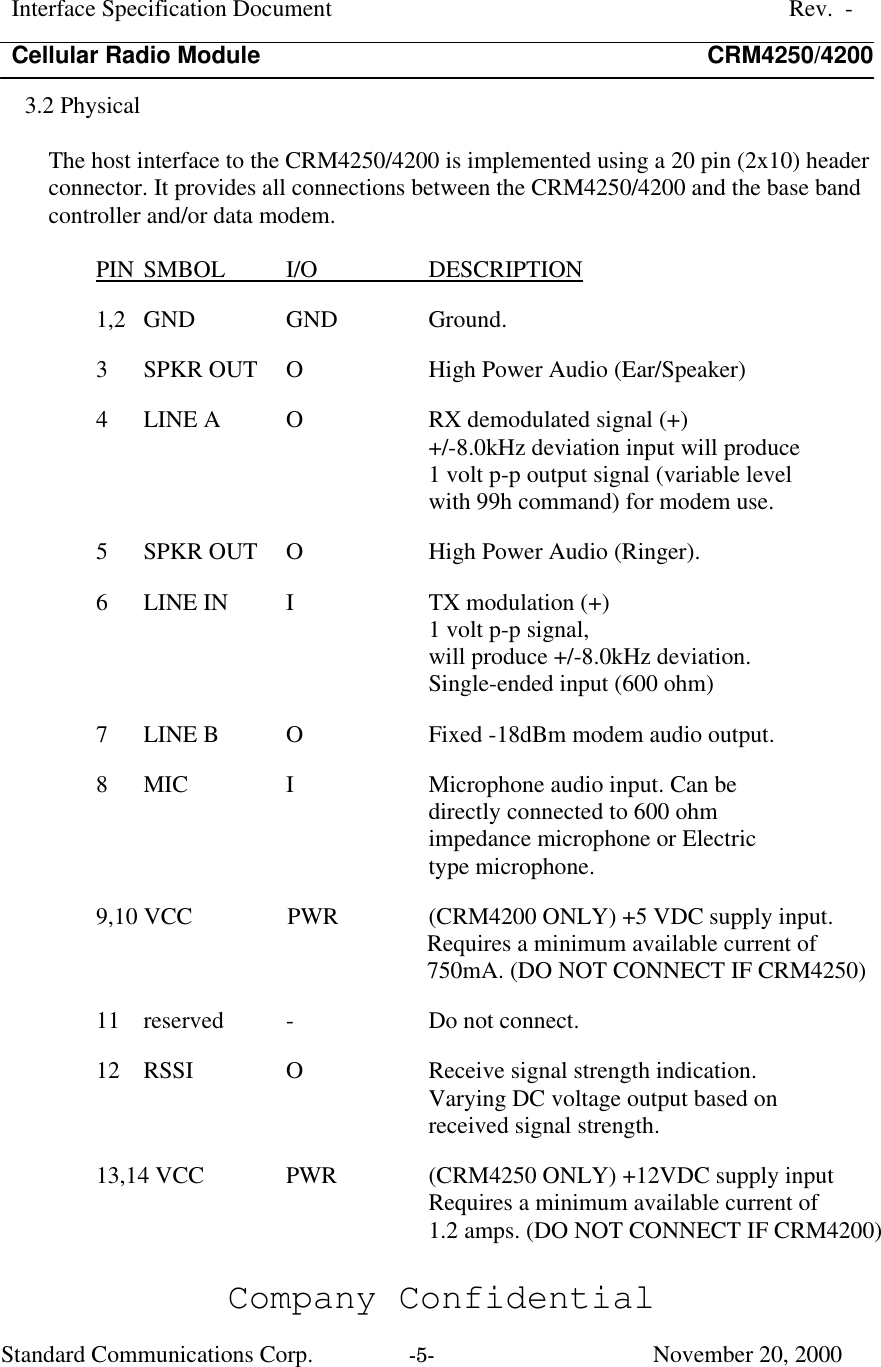
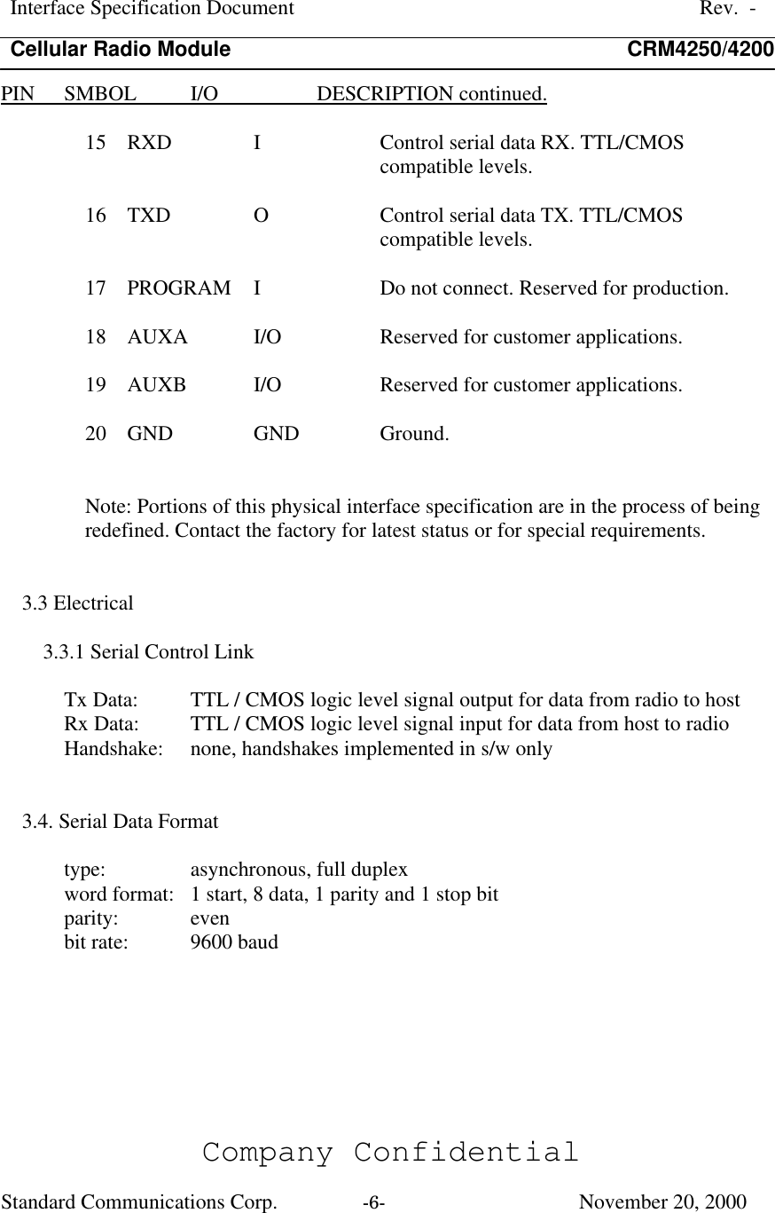
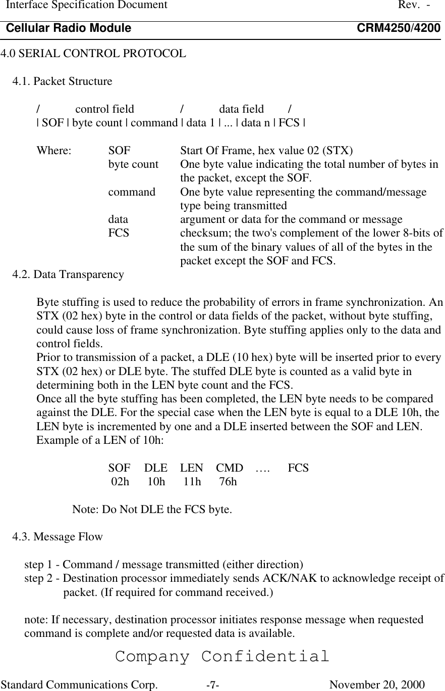
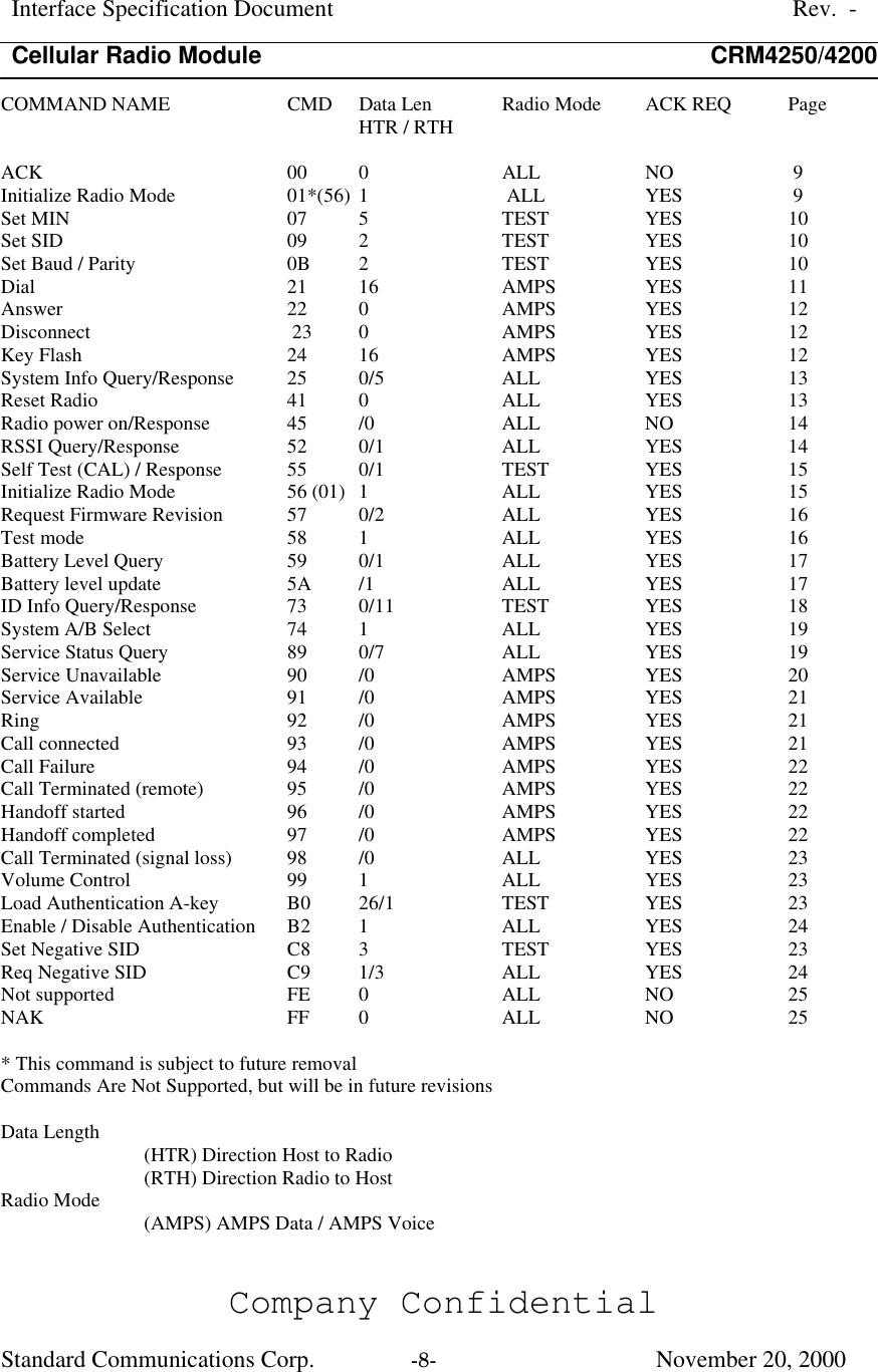
User Manual
Discussion / Help
Navigation