CalAmp 200G LMU-200 GPRS User Manual Main Title
CalAmp LMU-200 GPRS Main Title
UserManual.wiki
>
CalAmp
>
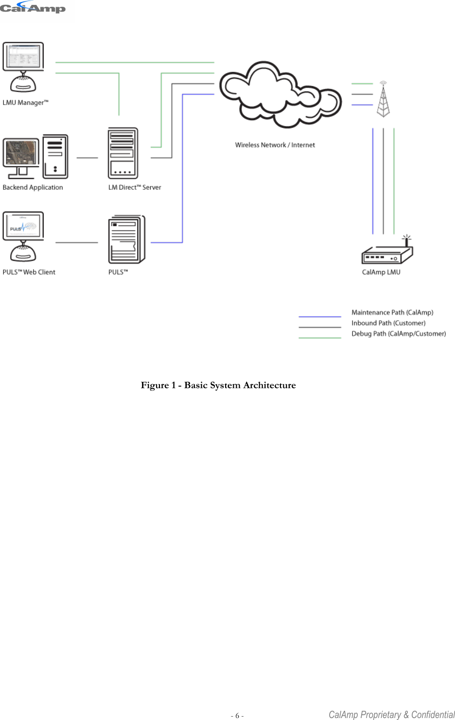
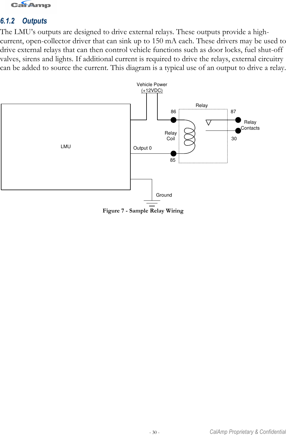
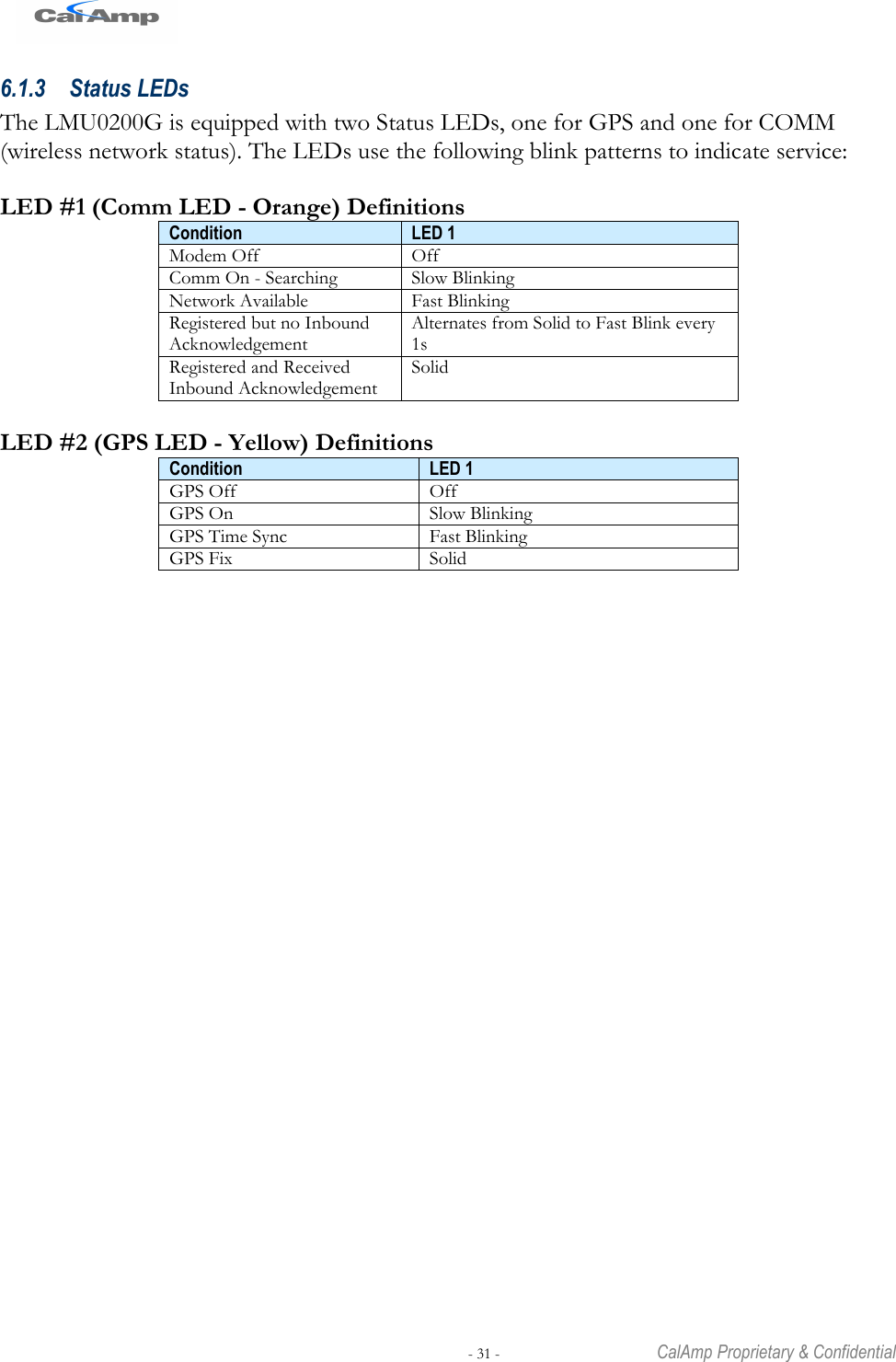
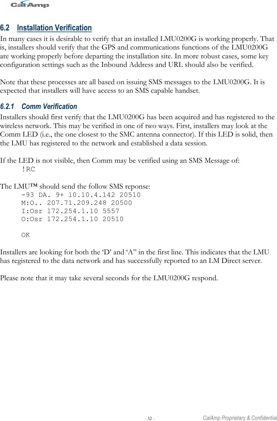
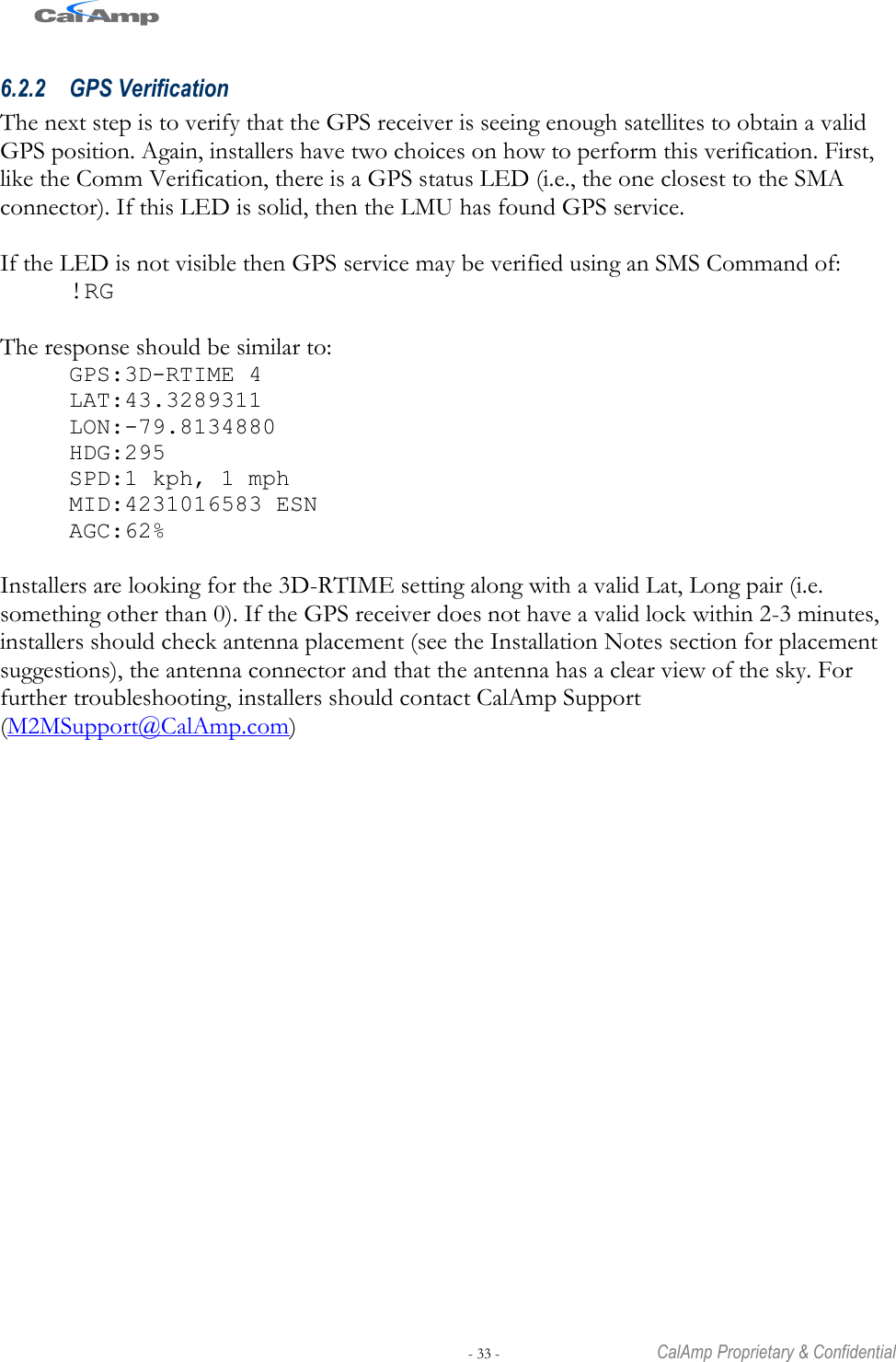
200G User Manual
LMU200_User Guide0124
Navigation menu
Upload a User Manual
Namespaces
Wiki Guide
HTML
PDF
Info
Views
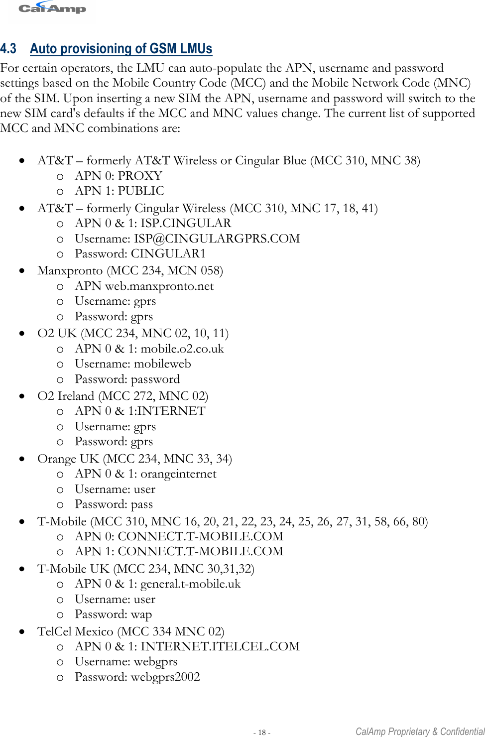
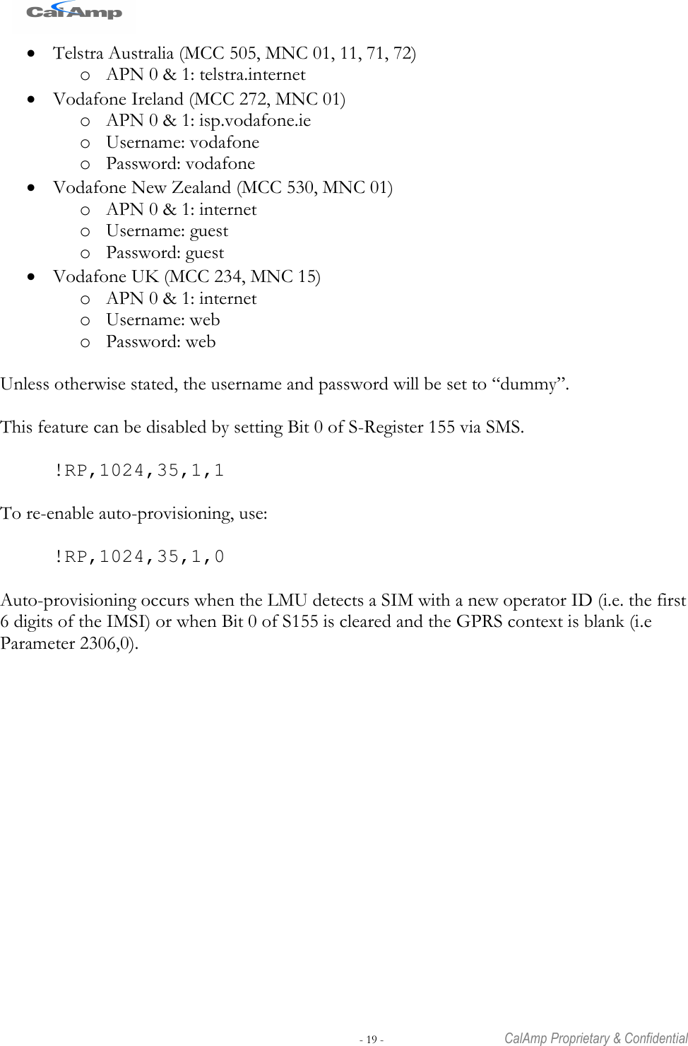
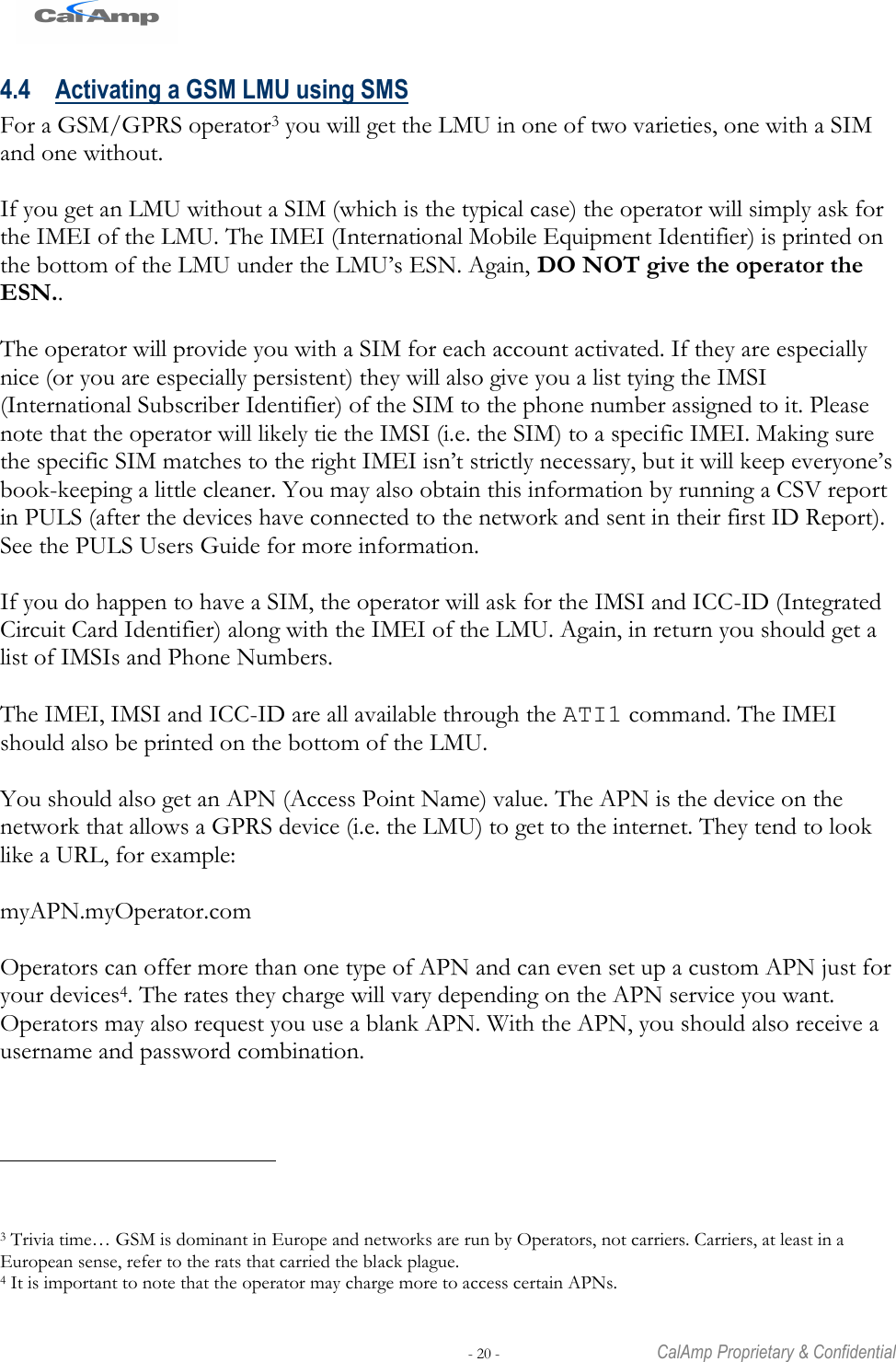
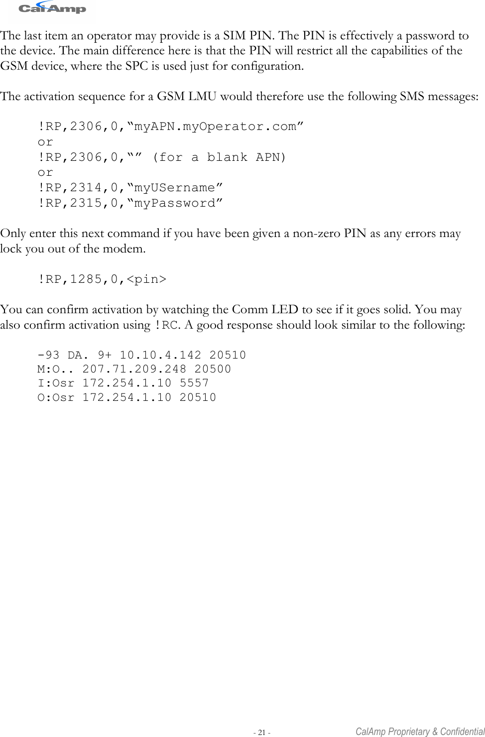
User Manual
Discussion / Help
Navigation