CalAmp 2630GBT GSM/GPRS 850/1900, Bluetooth and Bluetooth LE User Manual Main Title
CalAmp GSM/GPRS 850/1900, Bluetooth and Bluetooth LE Main Title
CalAmp >
Contents
- 1. User Manual
- 2. User Manual II
User Manual II
Copyright ©CalAmp DataCom Inc 2012 CalAmp Proprietary & Confidential
LMU-2x30™
Hardware and
Installation Guide
Version 1.1
March 2015

LMU-2x20™ Hardware and Installation Guide
V1.0.10 December 12, 2010
Copyright ©CalAmp DataCom Inc 2010 - ii - CalAmp Proprietary & Confidential
License Agreement
FOR SOFTWARE, APPLICATION PROGRAMING INTERFACES (APIS) & DOCUMENTATION
IMPORTANT: DO NOT INSTALL OR USE THE SOFTWARE OR DOCUMENTATION UNTIL YOU
HAVE READ AND AGREED TO THIS LICENSE AGREEMENT.
This is a legal agreement between you, the Customer, and CalAmp DataCom Incorporated (“CalAmp”). By installing and/or using
the software or documentation, you are consenting to the terms of this License. If you do not agree to the terms of this non-exclusive
License Agreement, DO NOT INSTALL OR USE THE SOFTWARE, APIs OR DOCUMENTATION. For a full refund, return
the unused media package and all accompanying materials within seven (7) days to CalAmp. Where there is no packaging or
media, use of the software and/or documentation constitutes acceptance.
DEFINITIONS: As used in this License Agreement, “Software” means CalAmp’s LM Direct™, LMU Manager™, LapTop Locator™,
LMU Application/Programmable Event Generator™, CDMA LMU Provisioning Tool, GPRS LMU Provisioning Tool, iDEN™
Provisioning Tool, LMU Status, Clone Config, Hex Dump, LM Exchange™ Traffic Monitor, Freewave Base Station Config, Remote
Serial Port, App Watcher Service and/or other software products licensed by CalAmp for use in computer applications development
or integration including the computer programs, libraries and related materials either contained on the media provided to you by or
from CalAmp, or which you have received or downloaded electronically. “Application” means a compiled or executable software
program created by Developer that uses some or all of the functionality of the Software. “Software Copies” means the actual copies
of all or any portion of the Software including backups, updates, merged or partial copies permitted hereunder or subsequently
licensed to you. “Documentation” means the non-Software information contained on the media provided with this package or
downloaded and which is used with and describes the operation and use of the Software. “Documentation Copies” means the actual
copies of all or any portion of the Documentation including backups, updates, merged or partial copies permitted hereunder or
subsequently provided to you. “Related Materials” means all other materials and whatever is provided by or from CalAmp, and the
non-Software and non-Documentation contained on the media supplied, downloaded, or otherwise supplied by or from CalAmp for
use with the Software and Documentation. “Server” means a single, networked computer that is accessible to other client machines
on the network. “User” means (i) a single person using an Application for his/her internal, use or (ii) a single terminal or a single
workstation of a computer used only by a person (and not accessed otherwise) for accessing an Application. “Use License” means
limited rights granted by CalAmp for deployment of a single Application to a User. “Developer” means a single programmer
developing an Application. “Developer License” means the grant of certain limited rights to use and maintain the Software, Software
Copies, Documentation, Documentation Copies and Related Materials in development of Applications.
BACKGROUND: A Developer License is required for each Developer who uses the Software in building Application(s). A Use License
is required and must be purchased by Customer for each User to which Customer provides access to an Application (unless a Server
or Site license for unlimited or a specified number of users has been purchased). Each Use License is specific to one client-side
Application only and may not be used for any other client-side Application. Each Server license is limited to Server-based
Applications deployed on that Server for which the license has been purchased as specified in a CalAmp License Certificate. The
Software is licensed on a per Developer, and on a per User, per Application basis. In order to preserve and protect its rights under
applicable law, CalAmp is not selling you ownership rights to Software or Documentation (owned by or licensed to CalAmp).
CalAmp specifically retains title to all CalAmp Software, Documentation and Related Materials and CalAmp licensors retain title to
items owned by them.
DURATION: This License Agreement is effective from the day you install or start using the Software, or receive or download it
electronically, and continues until terminated. If you fail to comply with any provision of the License, termination is automatic,
without notice from CalAmp and without the necessity for recourse to any judicial authority. Upon termination, you must destroy the
Related Materials, the Software, Documentation and all Software and Documentation copies. CalAmp can also enforce its other legal
and equitable rights.
DEVELOPER LICENSE ONLY—USES PERMITTED: Software and Documentation may be used for the sole purpose of developing
Applications and only by a licensed Developer. Software and Documentation may be installed onto a hard disk drive or a Server,
access to which is restricted to Developers for which a Developer License has been purchased and may also be stored or installed on a
storage device such as a network server, used only to install or access the Software or Documentation on your other computers over
an internal network; however, you must have acquired a license for each separate computer on which the Software or Documentation
is installed or accessed from the storage device. A Developer License may not be shared or used concurrently on different computers.
One backup copy may be made for each legally obtained media copy or electronic copy you have received, provided that all CalAmp
and third party licensor information — including copyright notices — are maintained and possession of the copy is retained in a
secure location. In addition, you agree to use reasonable efforts to protect the Software and Documentation from unauthorized use,
reproduction, distribution or publication. All rights not specifically granted in this License are reserved by CalAmp.

LMU-2x20™ Hardware and Installation Guide
V1.0.10 December 12, 2010
Copyright ©CalAmp DataCom Inc 2010 - iii - CalAmp Proprietary & Confidential
Customer agrees to include the notice “Copyright © 1999 – 2009 CalAmp DataCom Inc., All Rights Reserved” in Applications
developed with the Software. Customer agrees to include the following CalAmp Copyright and Government Restricted Use notice in
all documentation and in any Application on-line help or readme file.
“Portions of this computer program are owned by CalAmp DataCom Inc., Copyright © l999 – 2009, CalAmp DataCom Inc., All
Rights Reserved. Use, duplication or disclosure by the Government is subject to restrictions as set forth in subparagraph ©(1)(ii) of
the Rights in Technical Data and Computer Software clause at DFARS 252.227-7013 or subparagraphs ©(l) and (2) of the
Commercial Computer Software-Restricted Rights at 48 CFR 52.227-19, as applicable. Manufacturer is CalAmp DataCom Inc., 1401
North Rice Ave. Oxnard, CA 93030. Rights are reserved under copyright laws of the United States with respect to unpublished
portions of the Software.”
DEVELOPER(S) LICENSE—USES NOT PERMITTED: UNLESS OTHERWISE AGREED TO IN WRITING WITH CALAMP, YOU MAY NOT
(1) Make derivative works including but not limited to translations, adaptations, arrangements or any other alteration (each of which
would become the property of CalAmp or its licensors, as applicable) or make copies of the Software or Documentation except as
permitted above; (2) Make copies of the Related Materials; (3) Use any CalAmp product to translate the product of another licensor
unless you have the legal right to do so; (4) Allow a greater number of Developers to access the Software at any one time than the
total number of Developer licenses for which you have paid; (5) Rent, lease, sublicense or lend the Software, Software Copies,
Documentation, Documentation Copies, Related Materials or your rights under this License or allow access to the Software for
unlicensed users; (6) Alter, decompile (except to the limited extent that decompilation by the licensed Developer only is necessary as
the only available way to achieve interoperability with other programs and, in that situation, any resulting information cannot be used
in developing, producing or marketing any software substantially similar in expression to the Software), disassemble or reverse
engineer the Software; (7) Make any attempt to unlock or bypass any initialization system or encryption techniques utilized by the
Software or Documentation; (8) Alter, remove or obscure any proprietary legend, copyright or trademark notice contained in or on
Software, Documentation or Related Materials; or (9) use the Software to create an Application intended solely to duplicate
functionality of an existing CalAmp end user software product.
USE LICENSES: For each Server or Site License purchased, CalAmp grants the Customer the right to distribute Applications on a
single Server or at a single Site, as the case may be, accessible to the number of individual users (not concurrent users) for which the
Server or Site License has been purchased as evidenced by a CalAmp License Certificate. For each Use License purchased, as
evidenced by a CalAmp License Certificate, CalAmp grants the Customer the right to distribute a single Application to a single User.
In no circumstance may Customer distribute an Application under a site license or concurrent use license unless a comparable license
has been purchased for the Software as evidenced by a CalAmp License Certificate. Customer agrees that distribution of an
Application to a User will in all cases be accompanied by a license agreement containing at a minimum terms and conditions
substantially similar to and at least as restrictive as the following:
The User may not (1) Make derivative works including but not limited to translations, adaptations, arrangements or any other
alteration of the Application or make copies of the Application, except one backup copy may be made for each legally obtained copy
of the Application, provided that all CalAmp and third party licensor information — including copyright notices — are maintained
and possession of the copy is retained in a secure location; (2) Allow access to the Application for unlicensed users; (3) Rent, lease,
sublicense or lend the Application or its rights under the license; (4) Alter, decompile, disassemble or reverse engineer the Application;
(5) Make any attempt to unlock or bypass any initialization system or encryption technique utilized by the Application; or (6) Alter,
remove or obscure any proprietary legend, copyright or trademark notice contained in or on the Application.
The User agrees to use reasonable efforts to protect the Application from unauthorized use, reproduction, distribution or publication.
AUDIT: Customer shall keep records of all transactions involving Software for five (5) years after the transaction. CalAmp shall have
the right upon written notice to audit Customer’s records to verify compliance with this License including the number of Use
Licenses granted by Customer. Audit may take place at Customer’s place or business during normal working hours. In the event that
there is a discrepancy in excess of five percent (5%) between the number of Use Licenses granted and the number paid for, Customer
shall pay all costs related to performing the audit in addition to remitting payment for those licenses granted in excess of those paid
for as evidenced by a CalAmp License Certificate.
GENERAL: This Agreement represents our entire understanding and agreement regarding the Software, Software Copies,
Documentation, Documentation Copies and Related Materials and supersedes any prior purchase order, communication, advertising
or representation and may only be modified in a written amendment signed by an authorized CalAmp representative or by a specific
prior or subsequent written agreement between the parties. If any provision of this Agreement shall be unlawful, void or for any
reason unenforceable, that provision shall be deemed severable from, and shall in no way affect the validity or enforceability of, the
remaining provisions.

LMU-2x20™ Hardware and Installation Guide
V1.0.10 December 12, 2010
Copyright ©CalAmp DataCom Inc 2010 - iv - CalAmp Proprietary & Confidential
Limited Warranty
COVERING THE PHYSICAL MEDIA AND PRINTED MATERIALS: CalAmp warrants to you, the original licensee, that the media on
which the Software is recorded are free from defects in materials and workmanship under normal use and service FOR A PERIOD
OF NINETY (90) DAYS FROM THE DATE OF DEVELOPER LICENSE PURCHASE. CalAmp’s entire liability and your
exclusive remedy as to defective media, Documentation or Related Material(s) shall be replacement of the media, Documentation or
Related Material(s) by CalAmp. Each defective item, along with proof of license purchase and date, must be sent in a traceable
manner to: CalAmp DataCom Inc., 1401 North Rice Ave. Oxnard, CA 93030.
DISCLAIMER REGARDING THE SOFTWARE, DOCUMENTATIONS AND RELATED MATERIALS: THE SOFTWARE,
DOCUMENTATION AND RELATED MATERIALS ARE PROVIDED “AS IS.” EXCEPT AS MAY OTHERWISE BE
EXPRESSLY SET FORTH HEREIN, CALAMP MAKES NO REPRESENTATIONS OR WARRANTIES, EXPRESS OR
IMPLIED, WITH RESPECT TO THE SOFTWARE, DOCUMENTATION OR RELATED MATERIALS INCLUDING BY
WAY OF EXAMPLE, AND NOT LIMITATION, THE IMPLIED WARRANTIES OF MERCHANTABILITY AND FITNESS
FOR A PARTICULAR PURPOSE. BY WAY OF FURTHER EXAMPLE AND NOT LIMITATION, CALAMP MAKES NO
REPRESENTATIONS OR WARRANTIES, EXPRESS OR IMPLIED, WITH RESPECT TO THE ACCURACY, RELIABILITY
OR COMPLETENESS OF THE DOCUMENTATION OR THE RELATED MATERIALS. THE ENTIRE RISK AS TO THE
USE OF THE SOFTWARE, DOCUMENTATION AND RELATED MATERIALS IS ASSUMED BY YOU. IN NO EVENT
SHALL CALAMP BE LIABLE TO YOU OR ANY OTHER PERSON, REGARDLESS OF THE CAUSE, FOR THE
EFFECTIVENESS OR ACCURACY OF THE SOFTWARE, DOCUMENTATION OR RELATED MATERIALS OR FOR
ANY SPECIAL, INDIRECT, INCIDENTAL OR CONSEQUENTIAL DAMAGES ARISING FROM OR OCCASIONED BY
YOUR USE OF THE SOFTWARE, DOCUMENTATION OR RELATED MATERIALS, EVEN IF ADVISED OF THE
POSSIBILITY OF SUCH DAMAGES. IN THE EVENT THE FOREGOING IS FOUND BY A COURT OF COMPETENT
JURISDICTION TO BE INEFFECTIVE, YOU HEREBY AGREE THAT CALAMP’S MAXIMUM LIABILITY FOR ANY
CLAIM ARISING IN CONNECTION WITH THE SOFTWARE, DOCUMENTATION AND/OR RELATED MATERIALS
(WHETHER IN CONTRACT, TORT, INCLUDING NEGLIGENCE, PRODUCT LIABILITY OR OTHERWISE) SHALL
NOT EXCEED THE LICENSE FEES PAID BY YOU WITH RESPECT TO THE SOFTWARE, DOCUMENTATION
AND/OR RELATED MATERIALS AT ISSUE. SOME STATES DO NOT ALLOW THE LIMITATION OR EXCLUSION OF
INCIDENTAL OR CONSEQUENTIAL DAMAGES, SO THE FOREGOING PROVISION, WITH RESPECT TO
EXCLUDING OR LIMITING SUCH DAMAGES, MAY NOT APPLY TO YOU.
ACKNOWLEDGEMENT: You acknowledge that you have read this LIMITED WARRANTY, understand it and agree to be bound by
its terms and conditions. You also agree that: (1) No oral or written information or advice given by CalAmp, its dealers, distributors,
agents or employees shall in any way increase the scope of this Limited Warranty and you may not rely on any such information or
advice; (2) Unless a written governing agreement signed by you and CalAmp exists, this License Agreement is the complete and
exclusive statement of agreement between CalAmp and you regarding the licensing of the Software, Documentation and Related
Materials and supersedes all proposals, oral or written, and any other communications you may have had prior to purchasing your
license; (3) Except for the price and delivery terms agreed upon by both parties, the terms and conditions of this License Agreement
shall supersede those set forth in any purchase order where the purchase order conflicts or is inconsistent with or adds to the terms
and conditions of this License and those superseded purchase order terms and conditions shall be null and void; (4) You agree to
assure that copies of this License Agreement are distributed, read and agreed to by each Developer using the Software and/or
Documentation.
GOVERNING LAW: This Agreement shall be governed by the laws of the State of California, United States, excluding its conflicts of
law principles and excluding the United Nations Convention on Contracts for the International Sale of Goods. You agree to exclusive
jurisdiction of California State federal and state courts, Ventura County, for resolution of any dispute related to this Agreement.
U.S. GOVERNMENT PROTECTED RIGHTS: The Software Documentation and Related Materials are provided with RESTRICTED
RIGHTS. Use, duplication or disclosure by the Government is subject to restrictions as set forth in subparagraph ©(1)(ii) of the
Rights in Technical Data and Computer Software clause at DFARS 252.227-7013 or subparagraphs ©(1) and (2) of the Commercial
Computer Software-Restricted Rights at 48 CFR 52.227-19, as applicable. Manufacturer is CalAmp DataCom Inc., 1401 North Rice
Ave. Oxnard, CA 93030. Rights are reserved under copyright laws of the United States with respect to unpublished portions of the
Software.

LMU-2x20™ Hardware and Installation Guide
V1.0.10 December 12, 2010
Copyright ©CalAmp DataCom Inc 2010 - v - CalAmp Proprietary & Confidential
Regulatory Information
Human Exposure Compliance Statement
Pursuant to 47 CFR § 24.52 of the FCC Rules and Regulations, personal communications
services (PCS) equipment is subject to the radio frequency radiation exposure requirements
specified in § 1.1307(b), § 2.1091 and § 2.1093, as appropriate.
CalAmp DataCom Inc. certifies that it has determined that the LMU-2x30™ complies with
the RF hazard requirements applicable to broadband PCS equipment operating under the
authority of 47 CFR Part 24, Subpart E of the FCC Rules and Regulations. This
determination is dependent upon installation, operation and use of the equipment in
accordance with all instructions provided.
The LMU-2x30™ is designed for and intended to be used in fixed and mobile applications.
“Fixed” means that the device is physically secured at one location and is not able to be
easily moved to another location. “Mobile” means that the device is designed to be used in
other than fixed locations and generally in such a way that a separation distance of at least 20
cm is normally maintained between the transmitter’s antenna and the body of the user or
nearby persons. The LMU-2x30™ is not designed for or intended to be used in portable
applications (within 20 cm of the body of the user) and such uses are strictly prohibited.
To ensure that the LMU-2x30™ complies with current FCC regulations limiting both
maximum RF output power and human exposure to radio frequency radiation, a separation
distance of at least 20 cm must be maintained between the unit’s antenna and the body of
the user and any nearby persons at all times and in all applications and uses. Additionally, in
mobile applications, maximum antenna gain must not exceed 3 dBi.
Industry Canada:
This device complies with Industry Canada licence-exempt RSS standard(s). Operation
is subject to the following two conditions: (1) this device may not cause interference,
and (2) this device must accept any interference, including interference that may cause
undesired operation of the device.”
“Le présent appareil est conforme aux CNR d'Industrie Canada applicables aux
appareils radio exempts de licence. L'exploitation est autorisée aux deux conditions
suivantes : (1) l'appareil ne doit pas produire de brouillage, et (2) l'utilisateur de
l'appareil doit accepter tout brouillage radioélectrique subi, même si le brouillage est
susceptible d'en compromettre le fonctionnement. “

LMU-2x20™ Hardware and Installation Guide
V1.0.10 December 12, 2010
Copyright ©CalAmp DataCom Inc 2010 - vi - CalAmp Proprietary & Confidential
Transmitter Antenna information:
Antenna Type
Technology
Gain (dBi)
CalAmp (PCB Trace) Cellular -5.3 dBi
Johanson Technology
P/N 2450AT42A100
BT/ANT 0 (Peak)
RF Exposure Guidance:
This equipment complies with FCC and Industry Canada radiation exposure limits set forth
for an uncontrolled environment. This equipment should be installed and operated with
minimum distance 20cm between the radiator and your body. This transmitter must not be
co-located or operating in conjunction with any other antenna or transmitter not described
under this FCC ID and IC certification number, except in accordance with FCC and
Industry Canada multi-transmitter product procedures.”
RF exposition orientation : Cet équipement est conforme aux limites d'exposition aux
radiations de la FCC et d'Industrie Canada définies pour un environnement non contrôlé .
Cet équipement doit être installé et utilisé à distance minimum de 20cm entre le radiateur et
votre corps . Cet émetteur ne doit pas être co- localisées ou opérant en conjonction avec
tout autre antenne ou émetteur ne est pas décrite dans ce numéro d'identification FCC et IC
certification , sauf en conformité avec les procédures de produits multi- émetteur de la FCC
et d'Industrie Canada .

LMU-2x20™ Hardware and Installation Guide
V1.0.10 December 12, 2010
Copyright ©CalAmp DataCom Inc 2010 - vii - CalAmp Proprietary & Confidential
Table of Contents
License Agreement ................................................................................................................................................. ii
Limited Warranty ..................................................................................................................................................iv
Regulatory Information.......................................................................................................................................... v
Human Exposure Compliance Statement ............................................................................................................. v
1 INTRODUCTION ................................................................................................................................................................................................. 1
1.1 About This Manual ....................................................................................................................................... 1
1.2 About The Reader ......................................................................................................................................... 2
1.3 About CalAmp ............................................................................................................................................... 3
1.4 About the CalAmp Location Messaging Unit-2x30™ (LMU-2x30™) ...................................................... 4
2 SYSTEM OVERVIEW .......................................................................................................................................................................................... 5
2.1 Overview ........................................................................................................................................................ 5
2.2 Component Descriptions ............................................................................................................................... 7
2.2.1 Wireless Data Network .......................................................................................................................... 7
2.2.2 LMU-2x30™ ......................................................................................................................................... 7
2.2.3 LM Direct™ Server ............................................................................................................................... 7
2.2.4 Backend Software .................................................................................................................................. 7
2.2.5 PULS™ .................................................................................................................................................. 8
2.2.6 LMU Manager™ ................................................................................................................................... 8
2.3 Wireless Data Primer .................................................................................................................................... 9
2.3.1 SMS (Short Message Service) ............................................................................................................... 9
2.3.2 GPRS (General Packet Radio Service) .................................................................................................. 9
3 HARDWARE OVERVIEW ................................................................................................................................................................................... 10
3.1 Location Messaging Unit-2x30™ (LMU-2x30™) ..................................................................................... 10
3.1.1 LMU-2x30™ Handling Precautions .................................................................................................... 10
3.1.2 Environmental Specifications .............................................................................................................. 12
3.2 Primary Connector ..................................................................................................................................... 14
3.2.1 LMU-2x30™ -3 Wire Power Cable ..................................................................................................... 16
3.2.2 LMU-2x30™ – Full I/0 Wiring Harness – Part Number 5C867 ........................................................ 17
3.2.3 LMU-2x30™ - Serial Adapter ............................................................................................................. 18
3.2.4 LMU-2x30™ Miscellaneous Accessories ........................................................................................... 20
3.2.5 GPS Receiver ....................................................................................................................................... 22
3.3 Available Radio Interfaces ......................................................................................................................... 22
3.4 External RF Connector ............................................................................................................................... 22
CONFIGURATION AND ACTIVATION .............................................................................................................................................................................. 23
3.5 Configuration Quick Start Guide .............................................................................................................. 23
3.6 Quick Start - General Config ..................................................................................................................... 24
3.7 Auto provisioning of GSM LMUs .............................................................................................................. 25
3.8 Activating a GSM LMU using AT Commands ......................................................................................... 27
3.9 Accessing the SIM ....................................................................................................................................... 29
4 INSTALLING THE LMU .................................................................................................................................................................................... 31
4.1 Preparing for Installation ........................................................................................................................... 31
4.2 Plan The Installation ................................................................................................................................... 32
4.2.1 Size and Placement of LMU Unit ........................................................................................................ 32
4.2.2 Placement of Antennas ........................................................................................................................ 33
4.2.3 Access to the SIM (Subscriber Identity Module) Card ........................................................................ 36
4.2.4 Protection from Heat ............................................................................................................................ 36

LMU-2x20™ Hardware and Installation Guide
V1.0.10 December 12, 2010
Copyright ©CalAmp DataCom Inc 2010 - viii - CalAmp Proprietary & Confidential
4.2.5 Visibility of Diagnostic LEDs ............................................................................................................. 36
4.2.6 Cable Length ........................................................................................................................................ 36
4.2.7 Moisture and Weather Protection ........................................................................................................ 36
4.2.8 Preventing Accidental or Unauthorized Modification ......................................................................... 36
4.3 Installing the LMU in a Vehicle ................................................................................................................. 38
4.3.1 Place the LMU unit in the vehicle. ...................................................................................................... 38
4.3.2 Connect power, ignition, and ground. .................................................................................................. 38
4.3.3 Place the GPS antenna. ........................................................................................................................ 38
4.3.4 Mount the Comm. Antenna.................................................................................................................. 39
4.3.5 Typical Connection Sequence.............................................................................................................. 40
4.4 I/O Descriptions ........................................................................................................................................... 42
4.4.1 Ignition and Inputs ............................................................................................................................... 43
4.4.2 3-Axis Accelerometer Input ................................................................................................................. 45
4.4.3 Outputs ................................................................................................................................................. 45
4.4.4 Status LEDs ......................................................................................................................................... 46
4.5 Installation Verification .............................................................................................................................. 47
4.5.1 Comm Verification .............................................................................................................................. 47
4.5.2 GPS Verification .................................................................................................................................. 48
4.5.3 Inbound Verification ............................................................................................................................ 49
4.5.4 Verification via SMS ........................................................................................................................... 50
APPENDIX A - HYPERTERMINAL CONFIGURATION ......................................................................................................................................................... 53
APPENDIX B - WINDOWS VISTA - PUTTY SETUP ........................................................................................................................................................... 57

LMU-2x20™ Hardware and Installation Guide
V1.0.10 December 12, 2010
Copyright ©CalAmp DataCom Inc 2010 - 1 - CalAmp Proprietary & Confidential
1 Introduction
Welcome to the LMU-2x30™ Hardware and Installation Guide. This manual is intended to
give you information on the basic setup and installation of the CalAmp LMU-2x30™
product including hardware descriptions, environmental specifications, wireless network
overviews and device installation.
1.1 About This Manual
The LMU-2x30™ is one of the most flexible and economical mobile tracking hardware
products available. In order to accurately describe the functionality of these units we have
broken this manual into the following sections:
• System Overview: A basic description of a CalAmp LMU-2x30™ based tracking
system. This includes a description of roles and responsibilities of each of the
CalAmp components as well as a brief overview of the wireless data technologies
used by the LMU-2x30™.
• Hardware Overview: Describes the physical characteristics and interfaces of the
LMU-2x30™.
• Installation and Verification: Provides guidance for the installation of the LMU-
2x30™ in a vehicle and instructions on how to verify the installation is performing
adequately.

LMU-2x20™ Hardware and Installation Guide
V1.0.10 December 12, 2010
Copyright ©CalAmp DataCom Inc 2010 - 2 - CalAmp Proprietary & Confidential
1.2 About The Reader
In order to limit the size and scope of this manual, the following assumptions have been
made about the reader.
• You are familiar with GPS concepts and terminology
• You have some experience with installing equipment in vehicles
• You are familiar with the use of AT Commands
• You are familiar with the use of terminal programs such as HyperTerminal or PuTTY

LMU-2x20™ Hardware and Installation Guide
V1.0.10 December 12, 2010
Copyright ©CalAmp DataCom Inc 2010 - 3 - CalAmp Proprietary & Confidential
1.3 About CalAmp
CalAmp is a leading provider of wireless communications products that enable
anytime/anywhere access to critical information, data and entertainment content. With
comprehensive capabilities ranging from product design and development through volume
production, CalAmp delivers cost-effective high quality solutions to a broad array of
customers and end markets. CalAmp is the leading supplier of Direct Broadcast Satellite
(DBS) outdoor customer premise equipment to the U.S. satellite television market. The
Company also provides wireless data communication solutions for the telemetry and asset
tracking markets, private wireless networks, public safety communications and critical
infrastructure and process control applications. For additional information, please visit our
website at www.calamp.com.

LMU-2x20™ Hardware and Installation Guide
V1.0.10 December 12, 2010
Copyright ©CalAmp DataCom Inc 2010 - 4 - CalAmp Proprietary & Confidential
1.4 About the CalAmp Location Messaging Unit-2x30™ (LMU-2x30™)
The LMU-2x30™ fleet tracking unit offers leading edge technology including a new 3D
accelerometer for measuring driver behavior and vehicle impacts while offering high
reliability fleet customers demand.
Competitive Price, Competitive Technology, Competitive Edge
The LMU-2x30™ is a robust fleet device you can count on for AVL applications. The
LMU-2x30™ incorporates leading GSM-GPRS wireless communication and extra sensitive
GPS in an affordable package. High-sensitivity GPS and an internal antenna option also
means the device can be mounted virtually anywhere for less expensive installation. The
LMU-2x30™ also features 3D accelerometer to detect and act on hard braking, hard
acceleration, vehicle impacts, and crashes.
Flexibility
The LMU-2x30™ features CalAmp's industry leading advanced on-board alert engine that
monitors vehicle conditions giving you the most flexible tracking device in its class. The
PEG™ (Programmable Event Generator) application supports hundreds of customized
exception-based rules to help meet customers' dynamic requirements. Customers can modify
the behavior of the device to meet with range of applications preprogrammed before
shipment or in the field. Combining affordability and device intelligence with your unique
application can give you distinct advantages over your competition.
Over-the-Air Serviceability
The LMU-2x30™ also incorporates CalAmp's industry leading over-the-air device
management and maintenance system software, , PULS™ (Programming, Updates, and
Logistics System). Configuration parameters, PEG rules, and firmware can all be updated
over the air. Our web-based maintenance server, PULS™ scripts, and firmware, can all be
updated over-the-air. PULS™ offers out-of-the-box hands free configuration and automatic
post-installation upgrades. You can also monitor unit health status across your customers'
fleets to quickly identify issues before they become expensive problems.

LMU-2x20™ Hardware and Installation Guide
V1.0.10 December 12, 2010
Copyright ©CalAmp DataCom Inc 2010 - 5 - CalAmp Proprietary & Confidential
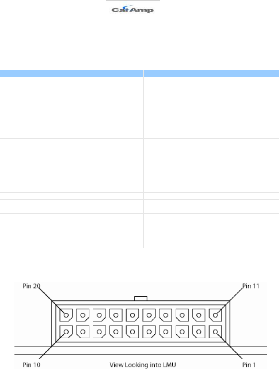
2 System Overview
2.1 Overview
The entire purpose behind a fleet management system is to be able to remotely contact a
vehicle, determine its location or status, and do something meaningful with that information.
This could include displaying the vehicle location on a map, performing an address look-up,
providing real-time driving directions, updating the vehicles ETA, monitoring vehicle and
driver status or dispatching the vehicle to its next pick up.
These functions, of course, are completely dependent on the capabilities of the vehicle
management application. The role of the CalAmp LMU-2x30™ is to deliver the location
information when and where it is needed.
A typical fleet management system based on a CalAmp device includes the following
components:
• A wireless data network
• An LMU-2x30™
• Host Device (GPS NMEA only)
• An LM Direct™ communications server
• Backend mapping and reporting software which typically includes mapping and fleet
reporting functions
• PULS™
• LMU Manager™
LMU-2x20™ Hardware and Installation Guide
V1.0.10 December 12, 2010
Copyright ©CalAmp DataCom Inc 2010 - 6 - CalAmp Proprietary & Confidential
Figure 1 - Basic System Architecture

LMU-2x20™ Hardware and Installation Guide
V1.0.10 December 12, 2010
Copyright ©CalAmp DataCom Inc 2010 - 7 - CalAmp Proprietary & Confidential
2.2 Component Descriptions
2.2.1 Wireless Data Network
The Wireless Data Network provides the information bridge between the LM Direct™
server and the LMU-2x30s™. Wireless data networks can take a variety of forms, such as
cellular networks, satellite systems or local area networks. At this point in time, the networks
available to the LMU-2x30™ are:
• GSM/GPRS
2.2.2 LMU-2x30™
The LMU-2x30™ is responsible for delivering the location and status information when and
where it is needed. Data requests can come from any of the following sources:
• PEG™ script within the LMU-2x30™
• A location or status request from the LM Direct™ server
• A location or status request from LMU Manager
• An SMS request made from a mobile device such as a customer’s cell-phone
In some cases, it is necessary to run an application in the vehicle while it is being tracked by
the backend software. Such examples could include instant messaging between vehicles or a
central office, in-vehicle mapping or driving directions, email or database access. In most of
these cases you will be using the LMU-2x30™ as a wireless modem as well as a vehicle-
location device.
2.2.3 LM Direct™ Server
LM Direct™ is a CalAmp proprietary message interface specification detailing the various
messages and their contents the LMU-2x30™ is capable of sending and receiving. This
interface allows System Integrators to communicate directly with LMU-2x30’s™. Please
refer to the LM Direct™ Reference Guide for details.
2.2.4 Backend Software
Backend software is a customer provided software application. Regardless of its purpose,
one of its primary functions is to parse and present data obtained from the LM Direct™
server. This allows the application to do any of the following:
• Display location database on reports received from the LMU-2x30™ in a variety of
formats
• Present historic information received from the LMU-2x30™, typically in a
report/chart style format
• Request location updates from one or more LMU-2x30s™
• Update and change the configuration of one or more LMU-2x30s™

LMU-2x20™ Hardware and Installation Guide
V1.0.10 December 12, 2010
Copyright ©CalAmp DataCom Inc 2010 - 8 - CalAmp Proprietary & Confidential
2.2.5 PULS™
PULS™ (Programming, Update and Logistics System) is CalAmp’s web-based maintenance
server offering out-of-the-box hands free configuration and automatic post-installation
upgrades. PULSTM provides a means for configuration parameters, PEG scripts, and
firmware to be updated Over-The-Air(OTA) and allows CalAmp customers to monitor unit
health status across your customers’ fleets to quickly identify issues before they become
expensive problems.
2.2.6 LMU Manager™
LMU Manager is the primary configuration tool in the CalAmp system. It allows access to
almost every feature available to the LMU-2x30™. Unlike the backend software, it has the
option of talking directly to an LMU-2x30™ or making a request forwarded by the LM
Direct™ server.
For further details on using LMU Manager, please refer to the LMU Manager Users Guide.

LMU-2x20™ Hardware and Installation Guide
V1.0.10 December 12, 2010
Copyright ©CalAmp DataCom Inc 2010 - 9 - CalAmp Proprietary & Confidential
2.3 Wireless Data Primer
This section is meant to give an overview of the wireless data technologies employed by the
CalAmp LMU-2x30™.
2.3.1 SMS (Short Message Service)
“The Short Message Service (SMS) is the ability to send and receive text messages to and
from mobile telephones. The text can comprise of words or numbers or an alphanumeric
combination. SMS was created as part of the GSM Phase 1 standard.”1
SMS message are typically text based, though binary messages are possible and can range in
size from 140 characters to 256 characters depending on the network being used.
2.3.2 GPRS (General Packet Radio Service)
“The General Packet Radio Service (GPRS) is a new non-voice value-added service that
allows information to be sent and received across a GSM mobile telephone network. It
supplements today's Circuit Switched Data and Short Message Service. GPRS is NOT
related to GPS (the Global Positioning System), a similar acronym that is often used in
mobile contexts.”2
GPRS is being deployed in its initial stages in approximately 52 countries around the world.
Keep in mind that GSM frequencies change depending on your geographic location. In
Europe, GSM sits in both the 900Mhz and 1.8GHz bands. In North America it sits in the
1.9GHz and 850 MHz bands. This means, that in order to roam with your GSM/GPRS
mobile between countries, it needs to be able to operate on multiple frequencies. The LMU-
2x30™ offers quad-band (850/900/1800/1900 MHz) capabilities to support networks
worldwide.
1 Excerpt taken from the GSM World website (http://www.gsmworld.com/technology/sms/intro.shtml#1)
2 Excerpt taken from the GSM World website (http://www.gsmworld.com/technology/gprs.html)

LMU-2x20™ Hardware and Installation Guide
V1.0.10 December 12, 2010
Copyright ©CalAmp DataCom Inc 2010 - 10 - CalAmp Proprietary & Confidential
3 Hardware Overview
3.1 Location Messaging Unit-2x30™ (LMU-2x30™)
3.1.1 LMU-2x30™ Handling Precautions
3.1.1.1 Electrostatic Discharge (ESD)
Electrostatic discharge (ESD) is the sudden and momentary electric current that flows
between two objects at different electrical potentials caused by direct contact or induced by
an electrostatic field. The term is usually used in the electronics and other industries to
describe momentary unwanted currents that may cause damage to electronic equipment.
3.1.1.2 ESD Handling Precautions
ESD prevention is based on establishing an Electrostatic Protective Area (EPA). The EPA
can be a small working station or a large manufacturing area. The main principle of an EPA
is that there are no highly charging materials in the vicinity of ESD sensitive electronics, all
conductive materials are grounded, workers are grounded, and charge build-up on ESD
sensitive electronics is prevented. International standards are used to define typical EPA and
can be obtained for example from International Electro-technical Commission (IEC) or
American National Standards Institute (ANSI).
This ESD classification of the sub assembly will be defined for the most sensitive
component, therefore the following classifications apply:
• Class 1B – Human Model (< 1 Kv)
• Class M1 – Machine Model (< 100V)
When handling the LMU-2x30’s™ main-board (i.e. sub assembly) by itself or in a partial
housing proper ESD precautions should be taken. The handler should be in an ESD safe
area and be properly grounded.
3.1.1.3 GPS Ceramic Patch Handling
When handling the sub assembly it may be natural to pick it up by sides and make contact
with the antenna boards. In an uncontrolled ESD environment contact with the center pin
of ceramic patch antenna can create a path for electrostatic discharge directly to the GPS
Module. The GPS Module is very sensitive to ESD and can be damaged and rendered non-
functional at low levels of ESD.
One should avoid contact with the center pin of the patch during handling. Going forward
the Factory will be placing a protective layer of Kapton® tape over the patch element to
eliminate this ESD path.

LMU-2x20™ Hardware and Installation Guide
V1.0.10 December 12, 2010
Copyright ©CalAmp DataCom Inc 2010 - 11 - CalAmp Proprietary & Confidential
3.1.1.4 Packaging
Anytime the sub assembly is shipped and it is not fully packaged in its final housing it must
be sealed in an ESD safe bag.
3.1.1.5 Electrical Over-Stress (EOS)
The GPS receiver can be damaged if exposed to an RF level that exceeds its maximum input
rating. Such exposure can happen if a nearby source transmits an RF signal at sufficiently
high level to cause damage.
3.1.1.6 Storage and Shipping
One potential source of EOS is proximity of one LMU-2x30™ GPS Antenna to another
LMU-2x30™ GSM Antenna. Should one of the units be in a transmit mode the potential
exists for the other unit to become damaged. Therefore any LMU-2x30™ GPS Antenna
should be kept at least four inches apart from any active LMU-2x30™ GSM Antenna or any
other active high power RF transmitter with power greater than 1 Watt.

LMU-2x20™ Hardware and Installation Guide
V1.0.10 December 12, 2010
Copyright ©CalAmp DataCom Inc 2010 - 12 - CalAmp Proprietary & Confidential
3.1.2 Environmental Specifications
The LMU-2x30™ is designed to operate in environments typically encountered by fleet
vehicles, including wide temperature extremes, voltage transients, and potential interference
from other vehicle equipment.
To ensure proper operation in such an environment, the LMU-2x30™ was subjected to
standard tests defined by the Society of Automotive Engineers (SAE). The specific tests
included temperature, shock, vibration, and EMI/EMC. These tests were performed by
independent labs and documented in a detailed test report. In accordance with Appendix A
of SAE J1113 Part 1, the Unit is considered a “Functional Status Class B, Performance
Region II” system that requires Threat Level 3 Testing.
The following shows the environmental conditions the LMU is designed to operate in and
the relevant SAE tests that were performed. No formal altitude tests were conducted.
Size
4.0" long x 2.0" wide x 0.85" high
10.2 cm long x 5.1 cm wide x 2.2 cm high
Weight
2.61 ounces / 75g (external antenna)
3.0 ounces / 85g (internal antenna)
Operating Temperature
-30o C to 75o C
Storage Temperature
-40o C to 85o C
Humidity
0% to 95% relative humidity, non-condensing
Shock and Vibration
SAE Test: SAE J1455 Compliant
Mil Standard 202G and 810F Compliant
Ground vehicle environment with associated shock and vibration
Electromagnetic Compatibility (EMC/EMI)
SAE Test: SAE J1113 Parts 2, 12, 21 and 41 Compliant
FCC Part 15B Compliant
Industry Canada Compliant
EMC compliant for a ground vehicle environment
Operating Voltage Range
6 – 32VDC

LMU-2x20™ Hardware and Installation Guide
V1.0.10 December 12, 2010
Copyright ©CalAmp DataCom Inc 2010 - 13 - CalAmp Proprietary & Confidential
Power Consumption
Active Standby :70mA at 12VDC
Sleep on Network (SMS): 10mA
Sleep on Network (GPRS): 20mA
Deep Sleep: 3mA
GPS
50 channel (with SBAS, DGPS) GPS Receiver
2m CEP (with SA off)
-160 dBm tracking sensitivity
Communications (Comm)
Quad Band Class 12 GPRS Modem
850 MHz (Class 4) – 2W
900 MHz (Class 4) – 2W
1800 MHz (Class 1) – 1W
1900 MHz (Class 1) -1 W
GPRS Packet Data (UDP)
SMS
RoHS Compliant
LMU-2x20™ Hardware and Installation Guide
V1.0.10 December 12, 2010
Copyright ©CalAmp DataCom Inc 2010 - 14 - CalAmp Proprietary & Confidential
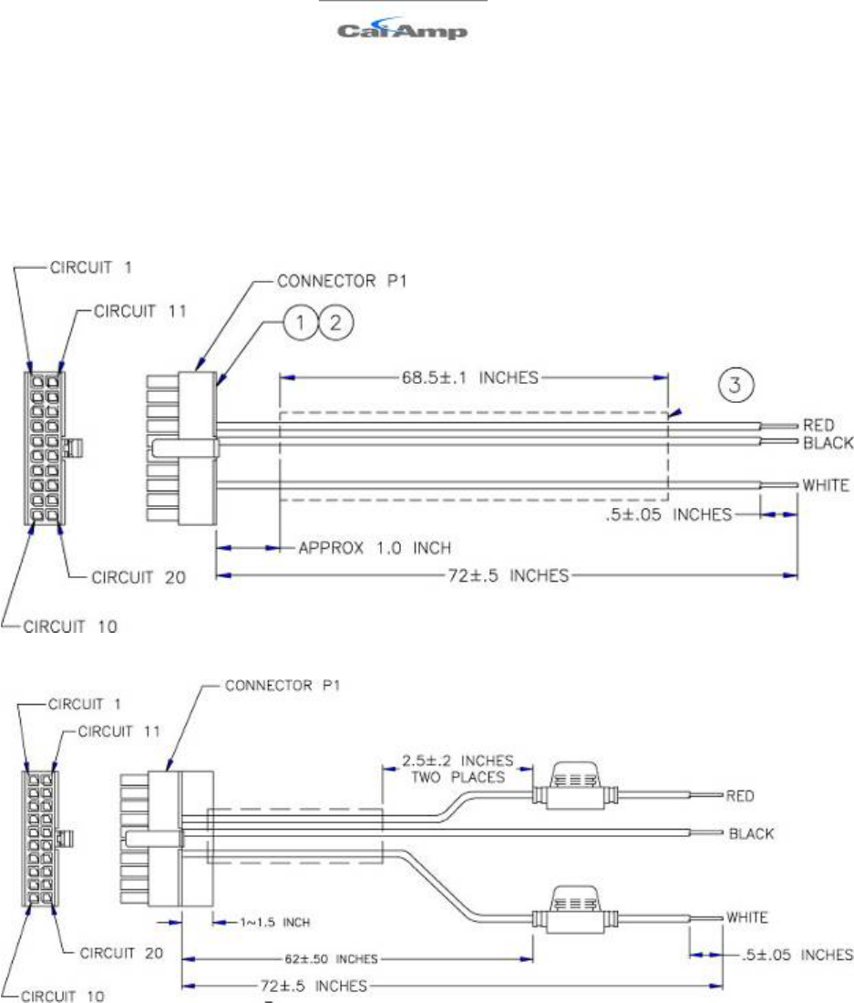
3.2 Primary Connector
The LMU-2x30™ uses a Male (pin) Molex Micro-Fit 3.0TM Dual Row, 20 circuit header to receive
power, ground and supply input and output signals. The pin out is as follows: <TBD> < – CHANGES FOR
THE 2x30>
Pin
Signal Name
Description
Lead Color
Input or Output
1
GND
Ground
Black (22 AWG)
Ground
2
OUT-0
Output 0 –Started Disable
Relay Driver
Orange (22 AWG)
Output
3
IN-1
Input 1 – Digital Input
Blue (22 AWG)
Input
4
TXD
Host TxD
Blue (22 AWG)
Input
5
ADC-1
Analog to Digital Input 1
Pink (22 AWG)
Input
6
IN-3
RESERVED
Violet (22 AWG)
7
IN-4
RESERVED
Grey (22 AWG)
8
IN-0
Ignition
White (20 AWG)
Input
9
V
DD
VDD Reference Output (20-
25mA Max)
Orange (22 AWG)
Output
10
OUT-1/BOOT
Output 1 – Digital Output
(Open Collector)
BOOT Input
Brown (22 AWG)
Input / Output
11
OUT-2
Output – 2 Digital Output
(Open Collector)
Yellow (22 AWG)
Output
12
IN-2
Input 2 – Digital Input
Orange (22 AWG)
Input
13
RxD
Host RxD
Green (22 AWG)
Output
14
VCC
Primary Power Input
Red (20 AWG)
Power
15
GND
Primary Ground
Black (20 AWG)
Ground
16
1BB-GND
1 Bit Bus Ground
Black (22 AWG)
Ground
17
1BB-D
1-Bit Bus Data
Input / Output
18
Aux - TxD
Aux Port - Transmit Data
<TBD>
Input
19
Aux -GND
Aux Port - Ground
<TBD>
Ground
20
Aux - RxD
Aux Port - Receive Data
<TBD>
Output
Figure 2 - LMU-2x30™ Header

LMU-2x20™ Hardware and Installation Guide
V1.0.10 December 12, 2010
Copyright ©CalAmp DataCom Inc 2010 - 15 - CalAmp Proprietary & Confidential
The mating connector for the LMU-2x30™ is the 3.00mm (.118") Pitch Micro-Fit 3.0™
Receptacle Housing, Dual Row, 20 Circuits connector. Part Number 430252000
(http://www.molex.com/pdm_docs/ps/PS-43045.pdf)
LMU-2x20™ Hardware and Installation Guide
V1.0.10 December 12, 2010
Copyright ©CalAmp DataCom Inc 2010 - 16 - CalAmp Proprietary & Confidential
3.2.1 LMU-2x30™ -3 Wire Power Cable
The standard power harness for the LMU-2x30™ comes in two varieties:
• Part Number 5C849-8: 20-pin basic 3-Wire Power Harness (unfused)
• Part Number 5C848-8: 20 pin basic w-Wire Power Harness (fused)
Figure 3 - Basic 3-Wire Power Harness - unfused
Figure 4 - Basic 3-Wire Power Harness - fused
LMU-2x20™ Hardware and Installation Guide
V1.0.10 December 12, 2010
Copyright ©CalAmp DataCom Inc 2010 - 17 - CalAmp Proprietary & Confidential
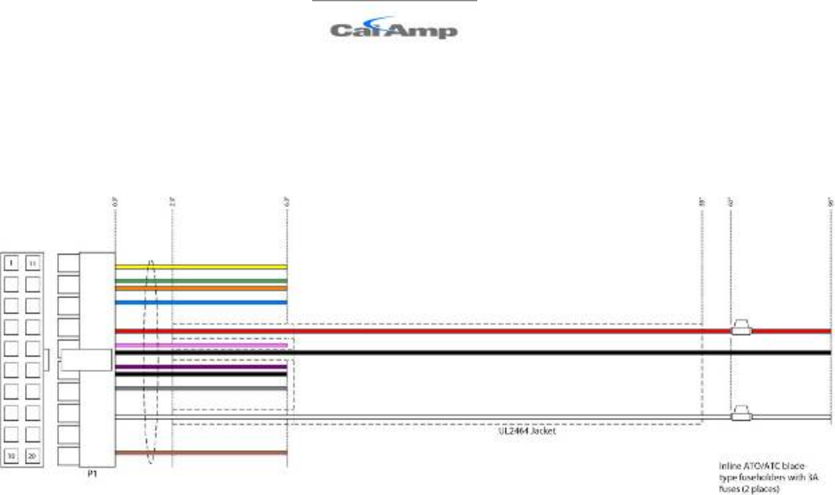
3.2.2 LMU-2x30™ – Full I/0 Wiring Harness – Part Number 5C867
This harness provides the complete set of I/O connectors including fused Power and
Ignition lines.
Figure 5 – Full I/O Wiring Harness
LMU-2x20™ Hardware and Installation Guide
V1.0.10 December 12, 2010
Copyright ©CalAmp DataCom Inc 2010 - 18 - CalAmp Proprietary & Confidential
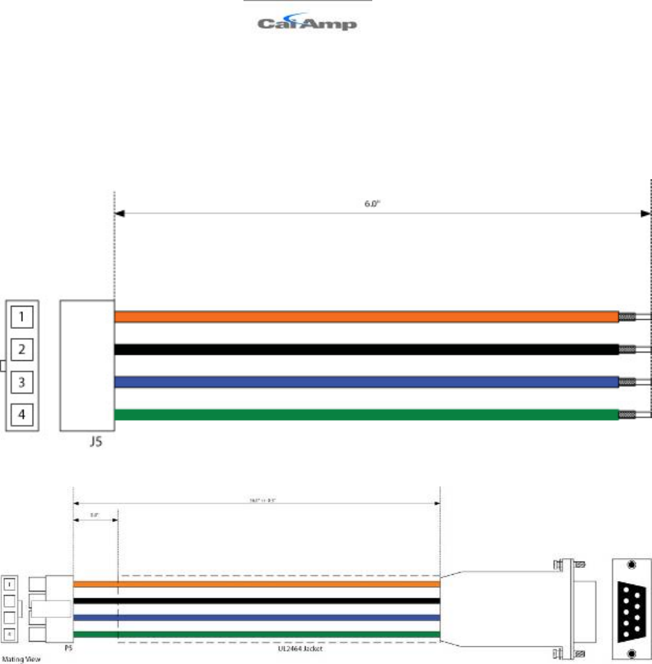
3.2.3 LMU-2x30™ - Serial Adapter
To add a host serial adapter to the LMU-2x30™ there are 2 additional parts:
• Part Number 133360: Serial Pigtail Adapter. This is connected to 5C867 to provide
a connection for the Serial Adapter itself
• Part Number 133337: Serial Adapter.
Figure 6 - LMU-2x30™ Serial Pigtail Adapter
Figure 7 – LMU-2x30™ Serial Adapter
LMU-2x20™ Hardware and Installation Guide
V1.0.10 December 12, 2010
Copyright ©CalAmp DataCom Inc 2010 - 19 - CalAmp Proprietary & Confidential
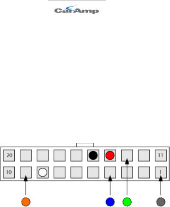
3.2.3.1 Attaching the Pig-Tail Serial Adapter
These instructions describe how to connect the Serial Pig-Tail Adapter to the LMU-2x30™’s
20 Pin wiring harness. It is recommended that the LMU be powered-off and the cable
detached when installing the lead kit. Insert crimped pins, one at a time into the back of the
20-pin wiring harness connector as indicated in the steps below.
1. Install Black ground lead to pin 1 of 20-pin connector on wiring
2. Install Blue TXD lead to pin 4 of 20-pin connector on wiring harness.(if pin 1 is
occupied, alternate locations are pin 16, and pin 19)
3. Install Green RXD lead to pin 13 of 20-pin connector on wiring harness
4. Install Orange VDD lead to pin 9 of 20-pin connector on wiring harness
Figure 8 - Back view of 20-pin connector
LMU-2x20™ Hardware and Installation Guide
V1.0.10 December 12, 2010
Copyright ©CalAmp DataCom Inc 2010 - 20 - CalAmp Proprietary & Confidential
3.2.4 LMU-2x30™ Miscellaneous Accessories
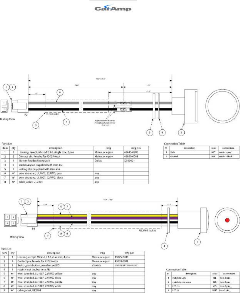
The following items are available from CalAmp for use with the LMU-2x30™’
• Part Number 4C763: iButton Reader and Cable Assembly
• Part Number 4C764: Switch LED Cable Assembly
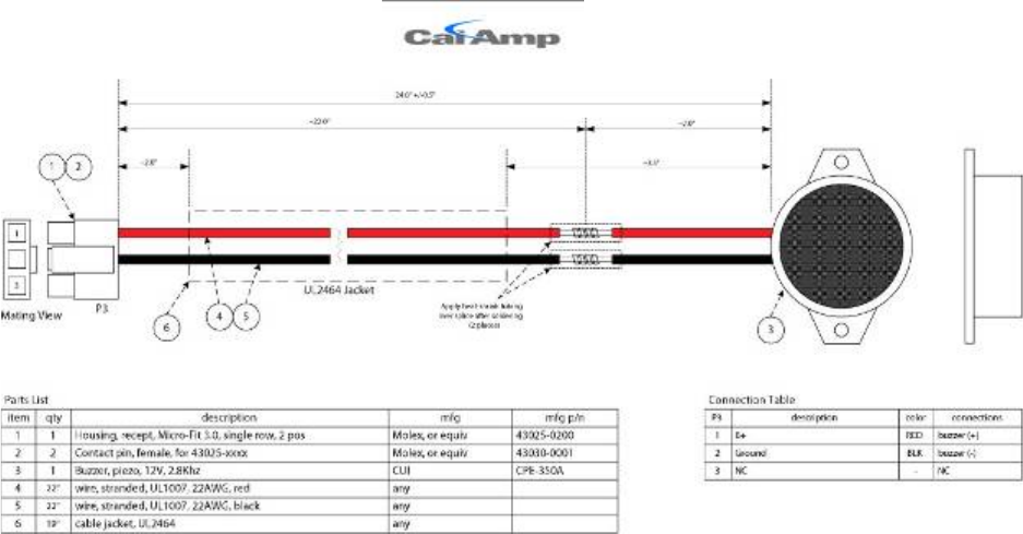
• Part Number 4C765: Buzzer and Cable Assembly
Figure 9 - iButton Reader and Cable Assembly
Figure 10 - Switch LED Cable Assumbly
LMU-2x20™ Hardware and Installation Guide
V1.0.10 December 12, 2010
Copyright ©CalAmp DataCom Inc 2010 - 21 - CalAmp Proprietary & Confidential
Figure 11 - Buzzer and Cable Assembly

LMU-2x20™ Hardware and Installation Guide
V1.0.10 December 12, 2010
Copyright ©CalAmp DataCom Inc 2010 - 22 - CalAmp Proprietary & Confidential
3.2.5 GPS Receiver
The LMU-1100™’s GPS receiver has the following specifications:
• 50 channel GPS receiver
• Accuracy: 2 meter CEP (with SA off)
• -160dBm Tracking Sensitivity
For external models, the antenna connector is SMA female.
Note that the CalAmp LMU-2x30™ requires an antenna amplifier that operates at 3VDC;
5VDC amps will not work.
3.3 Available Radio Interfaces
• GPRS – Built In Antenna
• GPRS – External Antenna
3.4 External RF Connector
The external antenna connection for the LMU-2x30™ is SMC with a 50 Ω nominal
impedance.

LMU-2x20™ Hardware and Installation Guide
V1.0.10 December 12, 2010
Copyright ©CalAmp DataCom Inc 2010 - 23 - CalAmp Proprietary & Confidential
Configuration and Activation
3.5 Configuration Quick Start Guide
This section details how to quickly get an LMU-2x30™ provisioned and configured to point
at a specific server. It is assumed that a PEG script has already been created and is being
managed through LMU Manager or PULS™, the CalAmp Maintenance System.
We are making three assumptions to simplify the setup process:
• You have created, installed and configured an LM Direct™ Server to receive
messages from the LMU-2x30™. (See LM Direct™ Reference Guide for details)
• You are using the standard wiring harness from CalAmp and the serial port
expansion harness.
• You have created a HyperTerminal or Putty session as described in Appendix A and
B respectively

LMU-2x20™ Hardware and Installation Guide
V1.0.10 December 12, 2010
Copyright ©CalAmp DataCom Inc 2010 - 24 - CalAmp Proprietary & Confidential
3.6 Quick Start - General Config
All LMU-2x30s™ must go through a common step during the configuration and
provisioning process. Specifically, this is pointing the LMU to the LM Direct™ server, either
via IP or a URL
This configuration process is accomplished via a series of AT Commands.
1. Power up the LMU-2x30™
2. Plug the serial cable into your laptop
3. Open a terminal session to the LMU-2x30™
4. Enter the address of the LM Direct™ server.
AT$APP PARAM 768,0,ddd.ddd.ddd.ddd
AT$APP PARAM 769,0,ppppp
where ddd.ddd.ddd.ddd is the publicly addressable IPV4 address of the server and
ppppp is the UDP port number
The LMU-2x30™ will respond with: OK
5. Alternatively if a URL has been set up it may be programmed with:
AT$APP PARAM 2319,0, “myURL.MyCompany.Com”
Where “myURL.MyCompany.com” is the URL assigned to the server, the LMU-
2x30™ will respond with: OK
Note that if you are not using a URL, this field must be cleared using:
AT$APP PARAM 2319,0, “”
6. Verify your settings by using:
AT$APP INBOUND?

LMU-2x20™ Hardware and Installation Guide
V1.0.10 December 12, 2010
Copyright ©CalAmp DataCom Inc 2010 - 25 - CalAmp Proprietary & Confidential
3.7 Auto provisioning of GSM LMUs
For certain operators, the LMU can auto-populate the APN, username and password
settings based on the Mobile Country Code (MCC) and the Mobile Network Code (MNC)
of the SIM. Upon inserting a new SIM the APN, username and password will switch to the
new SIM card's defaults if the MCC and MNC values change. The current list of supported
MCC and MNC combinations are:
• AT&T – formerly AT&T Wireless or Cingular Blue (MCC 310, MNC 38)
o APN 0: PROXY
o APN 1: PUBLIC
• AT&T – formerly Cingular Wireless (MCC 310, MNC 17, 18, 41)
o APN 0 & 1: ISP.CINGULAR
o Username: ISP@CINGULARGPRS.COM
o Password: CINGULAR1
• Manxpronto (MCC 234, MCN 058)
o APN web.manxpronto.net
o Username: gprs
o Password: gprs
• O2 UK (MCC 234, MNC 02, 10, 11)
o APN 0 & 1: mobile.o2.co.uk
o Username: mobileweb
o Password: password
• O2 Ireland (MCC 272, MNC 02)
o APN 0 & 1:INTERNET
o Username: gprs
o Password: gprs
• Orange UK (MCC 234, MNC 33, 34)
o APN 0 & 1: orangeinternet
o Username: user
o Password: pass
• T-Mobile (MCC 310, MNC 16, 20, 21, 22, 23, 24, 25, 26, 27, 31, 58, 66, 80)
o APN 0: CONNECT.T-MOBILE.COM
o APN 1: CONNECT.T-MOBILE.COM
• T-Mobile UK (MCC 234, MNC 30,31,32)
o APN 0 & 1: general.t-mobile.uk
o Username: user
o Password: wap
• TelCel Mexico (MCC 334 MNC 02)
o APN 0 & 1: INTERNET.ITELCEL.COM
o Username: webgprs
o Password: webgprs2002

LMU-2x20™ Hardware and Installation Guide
V1.0.10 December 12, 2010
Copyright ©CalAmp DataCom Inc 2010 - 26 - CalAmp Proprietary & Confidential
• Telstra Australia (MCC 505, MNC 01, 11, 71, 72)
o APN 0 & 1: telstra.internet
• Vodafone Ireland (MCC 272, MNC 01)
o APN 0 & 1: isp.vodafone.ie
o Username: vodafone
o Password: vodafone
• Vodafone New Zealand (MCC 530, MNC 01)
o APN 0 & 1: internet
o Username: guest
o Password: guest
• Vodafone UK (MCC 234, MNC 15)
o APN 0 & 1: internet
o Username: web
o Password: web
Unless otherwise stated, the username and password will be set to “dummy”.
This feature can be disabled by setting Bit 0 of S-Register 155.
AT$APP PARAM 1024,35,1,1
To re-enable auto-provisioning, use:
AT$APP PARAM 1024,35,1,0
Auto-provisioning occurs when the LMU detects a SIM with a new operator ID (i.e. the first
6 digits of the IMSI) or when Bit 0 of S155 is cleared and the GPRS context is blank (i.e
Parameter 2306,0).

LMU-2x20™ Hardware and Installation Guide
V1.0.10 December 12, 2010
Copyright ©CalAmp DataCom Inc 2010 - 27 - CalAmp Proprietary & Confidential
3.8 Activating a GSM LMU using AT Commands
For a GSM/GPRS operator3 you will get the LMU in one of two varieties, one with a SIM
and one without.
If you get an LMU without a SIM (which is the typical case) the operator will simply ask for
the IMEI of the LMU. The IMEI (International Mobile Equipment Identifier) is printed on
the bottom of the LMU under the LMU’s ESN. Again, DO NOT give the operator the
ESN of the LMU.
The operator will provide you with a SIM for each account activated. If they are especially
nice (or you are especially persistent) they will also give you a list tying the IMSI
(International Subscriber Identifier) of the SIM to the phone number assigned to it. Please
note that the operator will likely tie the IMSI (i.e. the SIM) to a specific IMEI. Making sure
the specific SIM matches to the right IMEI isn’t strictly necessary, but it will keep everyone’s
book-keeping a little cleaner. You may also obtain this information by running a CSV report
in PULS (after the devices have connected to the network and sent in their first ID Report).
See the PULS Users Guide for more information.
If you do happen to have a SIM, the operator will ask for the IMSI and ICC-ID (Integrated
Circuit Card Identifier) along with the IMEI of the LMU. Again, in return you should get a
list of IMSIs and Phone Numbers.
The IMEI, IMSI and ICC-ID are all available through the ATI1 command. The IMEI
should also be printed on the bottom of the LMU.
You should also get an APN (Access Point Name) value. The APN is the device on the
network that allows a GPRS device (i.e. the LMU) to get to the internet. They tend to look
like a URL, for example:
myAPN.myOperator.com
Operators can offer more than one type of APN and can even set up a custom APN just for
your devices4. The rates they charge will vary depending on the APN service you want.
Operators may also request you use a blank APN. With the APN, you should also receive a
username and password combination.
3 Trivia time… GSM is dominant in Europe and networks are run by Operators, not carriers. Carriers, at least in a
European sense, refer to the rats that carried the black plague.
4 It is important to note that the operator may charge more to access certain APNs.

LMU-2x20™ Hardware and Installation Guide
V1.0.10 December 12, 2010
Copyright ©CalAmp DataCom Inc 2010 - 28 - CalAmp Proprietary & Confidential
The last item an operator may provide is a SIM PIN. The PIN is effectively a password to
the device. The main difference here is that the PIN will restrict all the capabilities of the
GSM device, where the SPC is used just for configuration.
The activation sequence for a GSM LMU would therefore look as follows:
AT$APP PARAM 2306,0, “myAPN.myOperator.com”
AT$APP PARAM 2306,0, “” (for a blank APN)
AT$APP PARAM 2314,0,“myUSername”
AT$APP PARAM 2315,0,“myPassword”
Only enter this next command if you have been given a non-zero PIN as any errors may
lock you out of the modem.
AT$APP PARAM 1285,0,<SIM pin>
You can confirm activation by watching the Comm LED to see if it goes solid. You may
also confirm activation using ATIC A good response should look similar to the following:
GSM Registered: Yes
GPRS Registered: Yes
Connection: Yes
RSSI: -70 dBm
BER: 0
Channel: 0
Cell ID: 0
Base Station ID: 0
Local Area Code: 0
Network Code: 38
Country Code: 310
IMEI (Modem S/N): 500167110060440
IMSI (SIM S/N): 310380100521849
Phone Number:
GPRS APN: IP:Public
Quality of Srvc: 1,0,0,3,0,0
GSM Class: B
LMU-2x20™ Hardware and Installation Guide
V1.0.10 December 12, 2010
Copyright ©CalAmp DataCom Inc 2010 - 29 - CalAmp Proprietary & Confidential
3.9 Accessing the SIM
The following instructions should be used when attempting to access the SIM in a GSM
LMU-2x30™.
1. Remove the top plate of the LMU-2x30™. The LMU-2x30™’s enclosure is held
together by 4 plastic clips. To remove the cover, squeeze the top plate of the LMU
near the 20 pin header and pull up then repeat this action near the SIM cover.
2. Remove the top-plate to expose the top-side of the LMU-2x30™’s main-board.
3. Align the SIM so the contacts are facing up and the notch is facing into the LMU-
2x30™
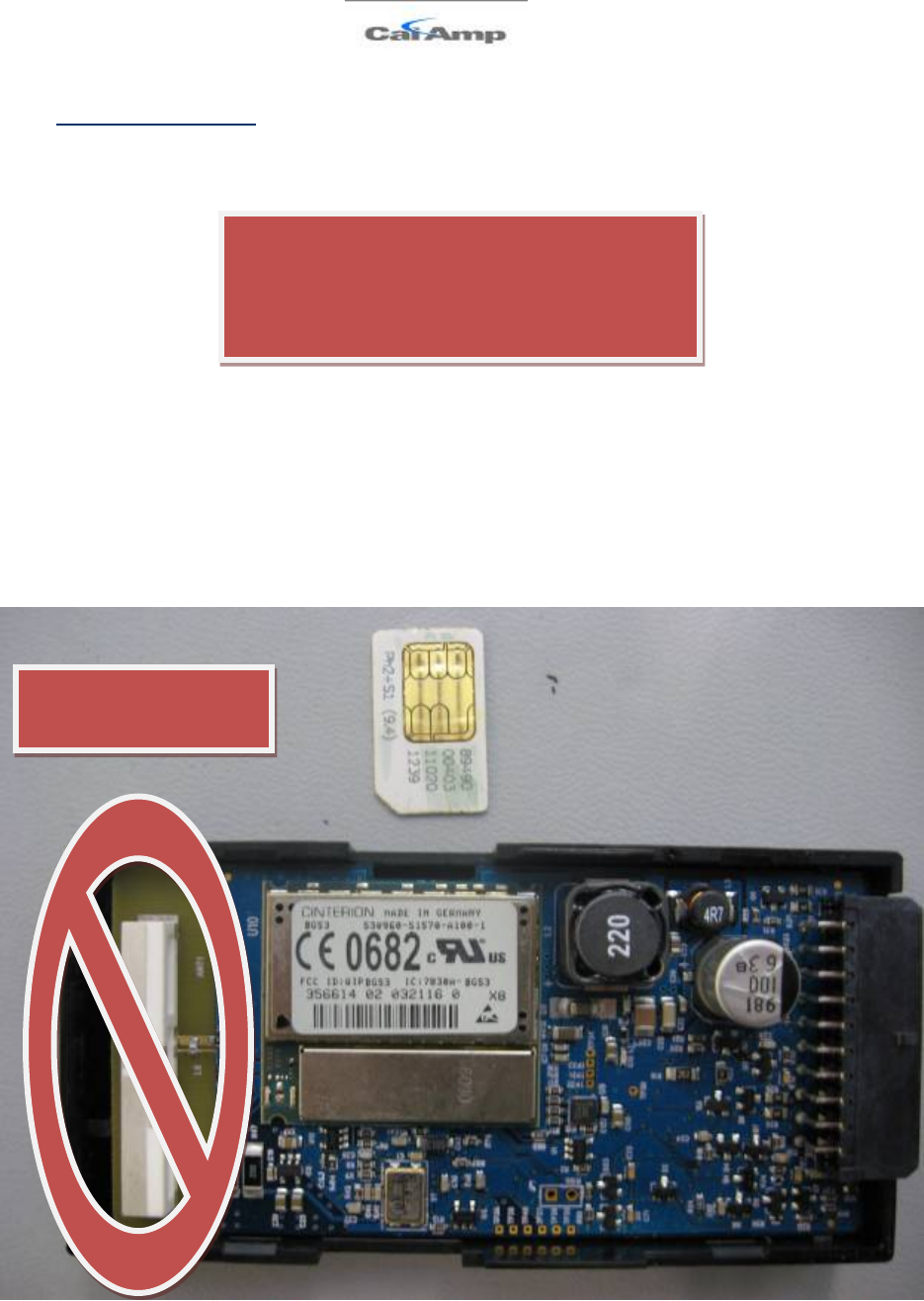
Figure 12 - LMU-2x30™ SIM Alignment
When opening the LMU-2x20™ take care
to not to touch the GPS Patch Antenna as
an accidental ESD discharges may render
it inoperable.
DO NOT TOUCH
THIS AREA
LMU-2x20™ Hardware and Installation Guide
V1.0.10 December 12, 2010
Copyright ©CalAmp DataCom Inc 2010 - 30 - CalAmp Proprietary & Confidential
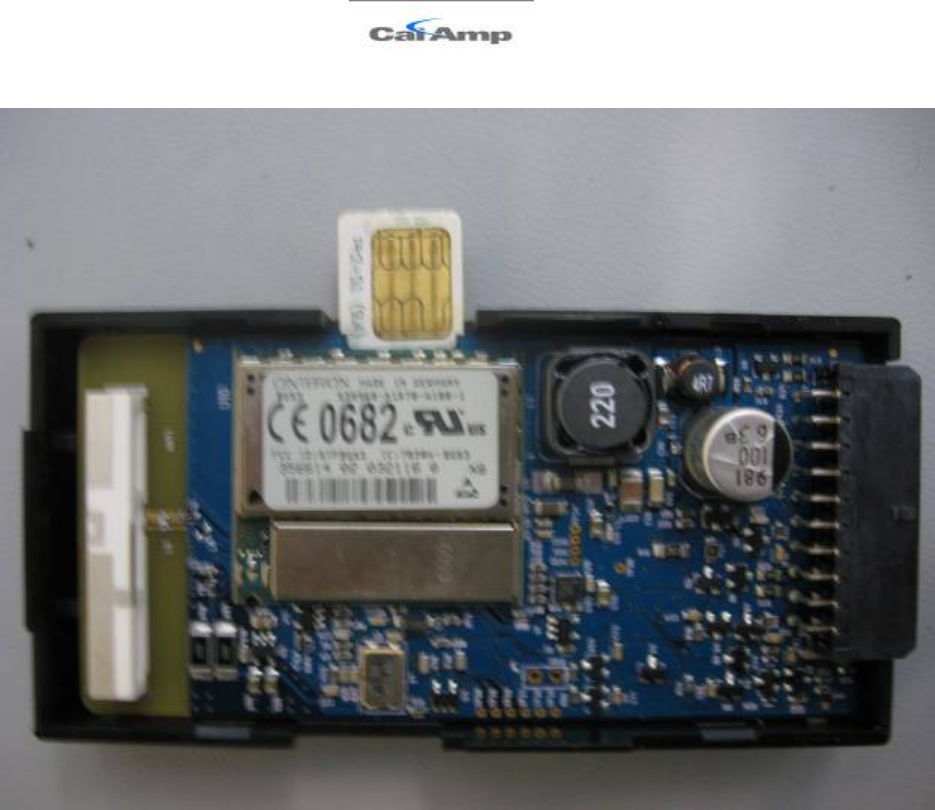
4. Insert the SIM into the LMU.
Figure 13 - LMU-2x30™ - Partially Inserted SIM
5. Snap the LMU-2x30™’s cover back in place.

LMU-2x20™ Hardware and Installation Guide
V1.0.10 December 12, 2010
Copyright ©CalAmp DataCom Inc 2010 - 31 - CalAmp Proprietary & Confidential
4 Installing the LMU
The installation of the LMU and its antennas can have a major impact on the LMU’s
performance. It is recommended that installers be familiar with the installation of GPS and
cellular devices and are comfortable in a vehicle environment.
4.1 Preparing for Installation
Be sure you have received all the LMU components you need. This must include:
• The LMU to be installed
• A power harness
• GPS Antenna
• Comm Antenna
• Optional Components:
o Input and output cables
o Relays
o Host serial devices (e.g. PDAs, laptops, other serial devices)

LMU-2x20™ Hardware and Installation Guide
V1.0.10 December 12, 2010
Copyright ©CalAmp DataCom Inc 2010 - 32 - CalAmp Proprietary & Confidential
4.2 Plan The Installation
Verify Power, Ground and Ignition. Be sure to check each source (power, ground and
ignition) to ensure that the proper signaling exists. This is typically accomplished with a
multi-meter.
Before drilling any holes or running any wires, decide where each hardware component will
be located (LMU, antennas, peripherals, etc.). Be sure that the cables to the LMU are not
bent or constricted in any way. Also make sure that the LMU is kept free from direct
exposure to the elements (sun, heat, rain, moisture etc...).
Be advised that an installation that violates the environmental specifications of the LMU will
void the warranty.
The best way to ensure a trouble-free installation is to consider your options and make some
decisions before you start. Take a look at the vehicle and determine how to best install the
LMU for the following purposes:
• Accurate data gathering and simulation of how customers actually use your solution
• Ongoing monitoring and maintenance of LMU equipment
• Accidental or intentional alteration of the equipment or cable connections
The following sections cover some of the issues to consider when planning your LMU
installation.
4.2.1 Size and Placement of LMU Unit
The dimensions of the LMU should be taken into account, particularly when installing in a
vehicle:
Whether you intend to place the LMU under a seat or into a cavity behind the vehicle’s
interior molded trim, be sure the LMU will fit before drilling any holes or running cable
• Be certain that the cables running to the LMU will not be bent or constricted.
Damage to the cables may impede the LMU’s performance.
• Be certain that the installation point will not violate any of the LMU’s environmental
specification (temperature, moisture, etc…) as improper installation of the LMU may
void the warranty.
See the LMU Environmental Specifications for the exact measurements and specifications of
the LMU-2x30™.
Typical installations will place the LMU under the vehicle dash board, or in the trunk. Make
sure you can get access to the unit afterwards as under some circumstances it may be
necessary to add additional wiring or connections to the LMU.

LMU-2x20™ Hardware and Installation Guide
V1.0.10 December 12, 2010
Copyright ©CalAmp DataCom Inc 2010 - 33 - CalAmp Proprietary & Confidential
4.2.2 Placement of Antennas
There are effectively three options for placements of an antenna:
• Roof-mount (magnetic or thru-hole)
• Glass-mount
• Covert (e.g. under the seat, dash, etc…)
CalAmp offers three antennas for customers to purchase:
• IV1353-QB-02 (Combined Comm and GPS antenna – Adhesive Covert Mount)
• RM1353-QB-02 (Combined Comm and GPS antenna – Covert Heavry Duty Screw
Mount)
• RM1353-TB-04 (Combined Comm and GPS antenna – Thru-hole roof or magnetic
mount)
LMU-2x20™ Hardware and Installation Guide
V1.0.10 December 12, 2010
Copyright ©CalAmp DataCom Inc 2010 - 34 - CalAmp Proprietary & Confidential
4.2.2.1 Comm Antenna Placement Guidelines
The Comm. Antenna must be located at least 20cm away from vehicle passengers, other
personnel, or bystanders in order to comply with FCC radio frequency exposure limits.
Typically, the Comm antenna used by the LMU for wireless service is a standard 3-dB gain
whip. It mounts with standard mounts (i.e. thru-hole, magnetic mount or peel and stick) and
requires a ground plane to work properly. If possible, it should be located at least 3 feet from
the GPS antenna. Ensure that the cable does not get crushed during installation.
Please note that the antennas provided by CalAmp combine both the GPS and Comm
portions.
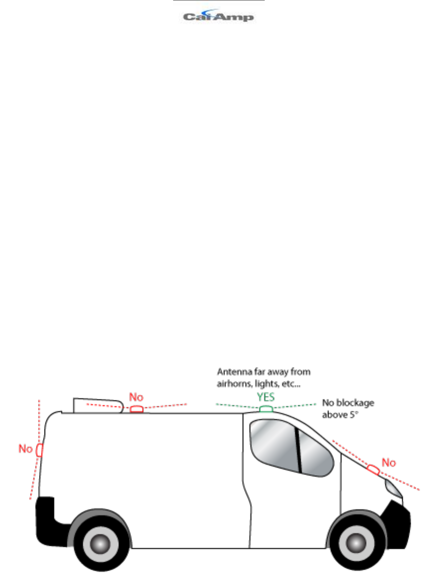
4.2.2.2 GPS Antenna Placement Guidelines
In order to maximize the performance of the LMU the GPS antenna should have a clear
view of the sky. When installing the GPS antenna on a vehicle, make sure that there are no
obstructions close to the antenna that might block the view 360° to the horizon. Things like
air horns, lights, vents, etc… should not block the antenna beyond 5° above the horizon.
The best location is usually near the center of the roof; however it is also desirable to locate
the cellular antenna as far from the GPS antenna as is practical.
14 Examples of good and poor GPS antenna placements
The received signal levels at the GPS antenna from the satellites are very low in power
(approximately -136 dBm), so any blockage of the antenna can affect the quality of the
location computed by the receiver. Kinks or tight knots in the antenna cable can also
LMU-2x20™ Hardware and Installation Guide
V1.0.10 December 12, 2010
Copyright ©CalAmp DataCom Inc 2010 - 35 - CalAmp Proprietary & Confidential
prevent the GPS receiver from operating properly. When laying out the antenna cable, care
should be taken so that the cable is not subjected to crushing or strain.
4.2.2.3 Placement of Combination and Internal Antennas
When dealing with combination antennas, it is more important to considered GPS
performance over Comm performance. GPS signal strengths are much lower than those
typically seen by cellular networks supported by the LMU. In order to maximize the
performance the LMU should have a clear view of the sky as possible. When installing the
GPS antenna in a vehicle, make sure that there are as few obstructions as possible close to
the LMU that might block the view 360° to the horizon. As with stand-alone GPS antennas,
nothing should not block the combination antenna beyond 5° above the horizon with the
best location being near the center of the roof. For more covert installs, directly under the
front or rear-windshields are also acceptable.
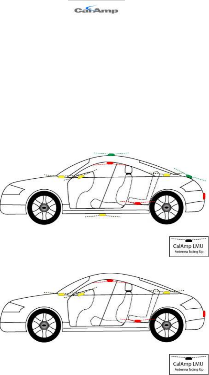
15 Examples of Good (Green), OK(Yellow) and Poor(Red) combo antenna placements
16 Examples OK(Yellow) and Poor(Red) internal antenna placements

LMU-2x20™ Hardware and Installation Guide
V1.0.10 December 12, 2010
Copyright ©CalAmp DataCom Inc 2010 - 36 - CalAmp Proprietary & Confidential
4.2.3 Access to the SIM (Subscriber Identity Module) Card
When used in a GSM or iDEN network, each LMU uses a Subscriber Identity Module (SIM)
card, which should be inserted before you install the LMU for the first time. The SIM card is
attached to the main-board inside the housing of the LMU unit.
At some future time, you might need or want to replace the SIM card with a different one,
so try to install the LMU in such a way that the cover can be removed to make the SIM card
accessible.
4.2.4 Protection from Heat
It is best not to place the LMU unit in an unusually warm location such as directly near
heater vents, near hot engine components or in direct sunlight. The maximum temperature
that can be tolerated by the LMU is described in the LMU Environmental Specifications
section.
4.2.5 Visibility of Diagnostic LEDs
Status LED lights on the front of the LMU unit can provide valuable information about the
operation of the LMU. When feasible, attempt to install the LMU in such a way that these
lights can be seen with reasonable ease.
You may find it useful to be able to view the LEDs periodically to make sure that the LMU
is operating properly. If at any time you should encounter a problem with the LMU, you
may need to read the LEDs in order to troubleshoot the problem. If you cannot fix the
LMU yourself, you will need to provide the LED information to CalAmp customer support.
For information about how to interpret the LEDs, see the Status LED Behavior section.
4.2.6 Cable Length
The RF cables which are provided for connecting to the LMU antennas should be used at
the length provided. Do not cut cables. Instead, coil any excess cable length, making sure not
to crimp or flatten the antenna cable.
4.2.7 Moisture and Weather Protection
The LMU unit must be located where it will not be exposed to moisture or water. In a
typical installation inside a vehicle this is not commonly thought to be a concern; however, it
might be best to avoid locating the LMU below a car’s cup holders, or where rain might
easily splash into the compartment when a door is opened.
4.2.8 Preventing Accidental or Unauthorized Modification
If you anticipate that fleet drivers or others might interfere with the LMUs once they are
installed, take steps to be sure that it is not easy to disconnect the antenna wiring, remove
the LMU from its power source, etc.

LMU-2x20™ Hardware and Installation Guide
V1.0.10 December 12, 2010
Copyright ©CalAmp DataCom Inc 2010 - 37 - CalAmp Proprietary & Confidential
Two common methods are the use of Tamper Proof Sealant or creation of PEG Script to
detect power loss or GPS antenna disconnections.

LMU-2x20™ Hardware and Installation Guide
V1.0.10 December 12, 2010
Copyright ©CalAmp DataCom Inc 2010 - 38 - CalAmp Proprietary & Confidential
4.3 Installing the LMU in a Vehicle
This section provides instructions for installing an LMU in a vehicle.
Be sure to consider the design decisions described in the previous sections. When you are
ready to begin installing the LMU, follow these steps:
4.3.1 Place the LMU unit in the vehicle.
Typically, the LMU should be placed under the passenger seat or dashboard of the vehicle.
LMUs with internal antennas should be placed to maximize their GPS performance. A
typical location include under the dash close to the front wind-shield.
Attach the LMU to the solid body of the vehicle, not to plastic panels. The LMU can be
placed out of sight by removing interior trim and molding to expose available space, then
replacing the trim once the LMU is in place.
4.3.2 Connect power, ignition, and ground.
The power input (red wire) must be connected to a constant (un-switched) +12 VDC or
+24 VDC supply; preferably, connected directly to the vehicle battery terminal or as close to
it as possible. This connection point should be fuse protected to not more than 5 Amps.
The ignition input (white wire) must be connected to the vehicle ignition or another
appropriate key operated line, such as ACCESSORY, ensuring that power to the ignition
wire is available only when the vehicle ignition is on.
The ground line (black wire) must be connected to chassis ground.
Failure to connect these lines in the manner described may result in discharge of the vehicle
battery.
For best results, it is strongly recommended that the LMU connection be on its own circuit.
Connect the power input directly to the vehicle battery if possible and protect the circuit
with an inline fuse. If you must connect through the fuse box, use standard commercial
wiring practices to create a permanent installation rather than using press-in fuse clips or
other temporary measures.
DO NOT connect the power cable to the LMU at this time.
4.3.3 Place the GPS antenna.
The GPS antenna must have a clear view of the sky. Mount the GPS antenna on the
vehicle’s highest point (for example, the roof of a car). Make sure that there are no
obstructions close to the antenna that might block the view 360° to the horizon. Air horns
lights, vents, etc.. should not block the antenna beyond 5° above the horizon.
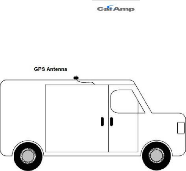
LMU-2x20™ Hardware and Installation Guide
V1.0.10 December 12, 2010
Copyright ©CalAmp DataCom Inc 2010 - 39 - CalAmp Proprietary & Confidential
Kinks or knots in the antenna cable can prevent the GPS receiver from operating properly.
When laying out the antenna cable, take care that the cable is not subjected to crushing or
strain.
The ideal location is typically near the center of the vehicle’s roof. However, it is also
desirable to locate the cellular antenna as far from the GPS antenna as possible.
Figure 17 - GPS Antenna Location
4.3.4 Mount the Comm. Antenna.
When using separate Comm and GPS antennas, it is best to locate the Comm. Antenna at
least 3 feet from the GPS antenna. Ensure that the cable is not crushed during installation or
normal vehicle operation.
Again, the Comm. Antenna must be located at least 20cm away from vehicle passengers,
other personnel, or bystanders in order to comply with FCC radio frequency exposure limits.
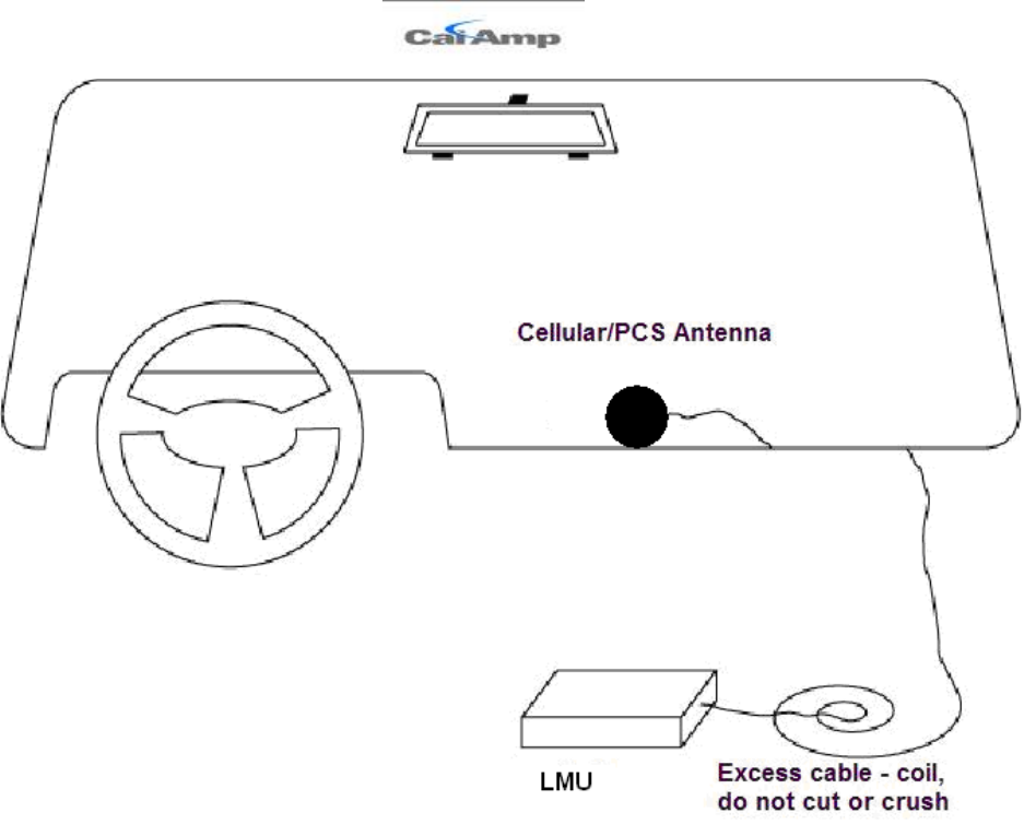
LMU-2x20™ Hardware and Installation Guide
V1.0.10 December 12, 2010
Copyright ©CalAmp DataCom Inc 2010 - 40 - CalAmp Proprietary & Confidential
Figure 18 - Window Mount Antenna Location
4.3.5 Typical Connection Sequence
• Attach the cable from the GPS antenna.
• Connect the cable from the Comm.. antenna
• Connect any peripherals to the LMU
• Plug in the power harness.
The physical installation of the LMU hardware is now complete.
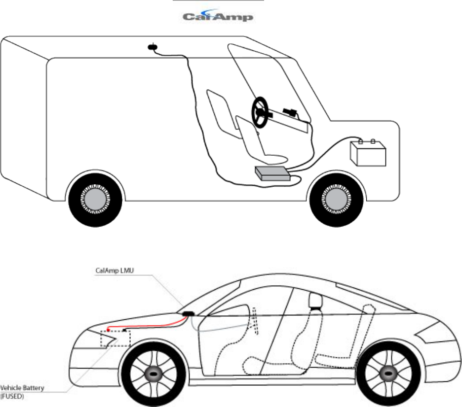
LMU-2x20™ Hardware and Installation Guide
V1.0.10 December 12, 2010
Copyright ©CalAmp DataCom Inc 2010 - 41 - CalAmp Proprietary & Confidential
Figure 19 - Completed Install – separate antennas
Figure 20 - Completed Install - Internal antennas

LMU-2x20™ Hardware and Installation Guide
V1.0.10 December 12, 2010
Copyright ©CalAmp DataCom Inc 2010 - 42 - CalAmp Proprietary & Confidential
4.4 I/O Descriptions
The LMU-2x30™ provides the following I/O:
Digital Inputs
• Input 0: Ignition Sense (Always biased low)
• Input 1: Generic Digital Input (always biased low)
• Input 2: Generic Digital Input (always biased high)
• Input 3: Generic Digital Input (always biased high
• Input 4: Generic Digital Input (always biased high
• Input 5: Motion Sensor (low = no motion, high = motion)
Analog to Digital Inputs
• A/D 0: External Power Supply Monitor
• A/D 1: Generic External A/D Input
• A/D 2: GPS Antenna Monitor
Outputs:
• Output 0: Standard Open Collector Relay Output (150mA)
• Output 1: Standard Open Collector Relay Output (150mA)
• Output 2: Standard Open Collector Relay Output (150mA)
1-Wire® Interface
• Temperature Sensor Support
• iButton ID Support (based on S1171 settings)

LMU-2x20™ Hardware and Installation Guide
V1.0.10 December 12, 2010
Copyright ©CalAmp DataCom Inc 2010 - 43 - CalAmp Proprietary & Confidential
4.4.1 Ignition and Inputs
The LMU-2x30™ provides up to 5 external inputs and one internal. The external inputs are
protected from typical vehicle transients and can be directly connected to most vehicle level
logical inputs from 4 volts up to the vehicle power input level (typically 12 VDC). Their
input impedance is approximately 10kΩ. One of these inputs is dedicated to sensing the
vehicle’s ignition status to provide for flexible power management. The other two inputs
may be used to sense vehicle inputs such as cooling unit operation, a hidden driver “Panic”
switch, taxi on-duty/off-duty meter status or many others.
The ignition input is pulled to ground through the 10k resistance, where the other inputs can
either be normally High (i.e. pulled to +12v through a 10k resistor) or Low (i.e. pulled to
ground through a 10k resistor). Input 1 is always biased low, inputs, 2-4 are biased high The
diagrams below show how to connect the inputs in both a high- and low-biased
configuration:
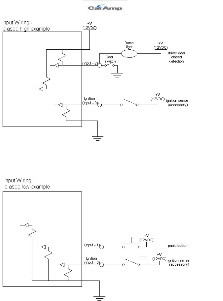
LMU-2x20™ Hardware and Installation Guide
V1.0.10 December 12, 2010
Copyright ©CalAmp DataCom Inc 2010 - 44 - CalAmp Proprietary & Confidential
Figure 21 - Sample Input Wiring
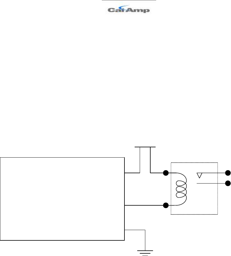
LMU-2x20™ Hardware and Installation Guide
V1.0.10 December 12, 2010
Copyright ©CalAmp DataCom Inc 2010 - 45 - CalAmp Proprietary & Confidential
4.4.2 3-Axis Accelerometer Input
The LMU-2x30™ supports an internal 3 Axis Precision Accelerometer as one of its discreet
inputs. When the LMU is moved in any direction, the associated input will be in the High
state. If the LMU’s accelerometer does not detect motion, then the input will be in the Low
state. No external connections are required for this functionality to be operational.
4.4.3 Outputs
The LMU’s outputs are designed to drive external relays. These outputs provide a high-
current, open-collector driver that can sink up to 150 mA each. These drivers may be used to
drive external relays that can then control vehicle functions such as door locks, fuel shut-off
valves, sirens and lights. If additional current is required to drive the relays, external circuitry
can be added to source the current. This diagram is a typical use of an output to drive a relay.
Vehicle Power
(+12VDC)
Relay
Coil
Relay
Contacts
Relay
Ground
LMU
85
86 87
30
Output 0
Figure 22 - Sample Relay Wiring
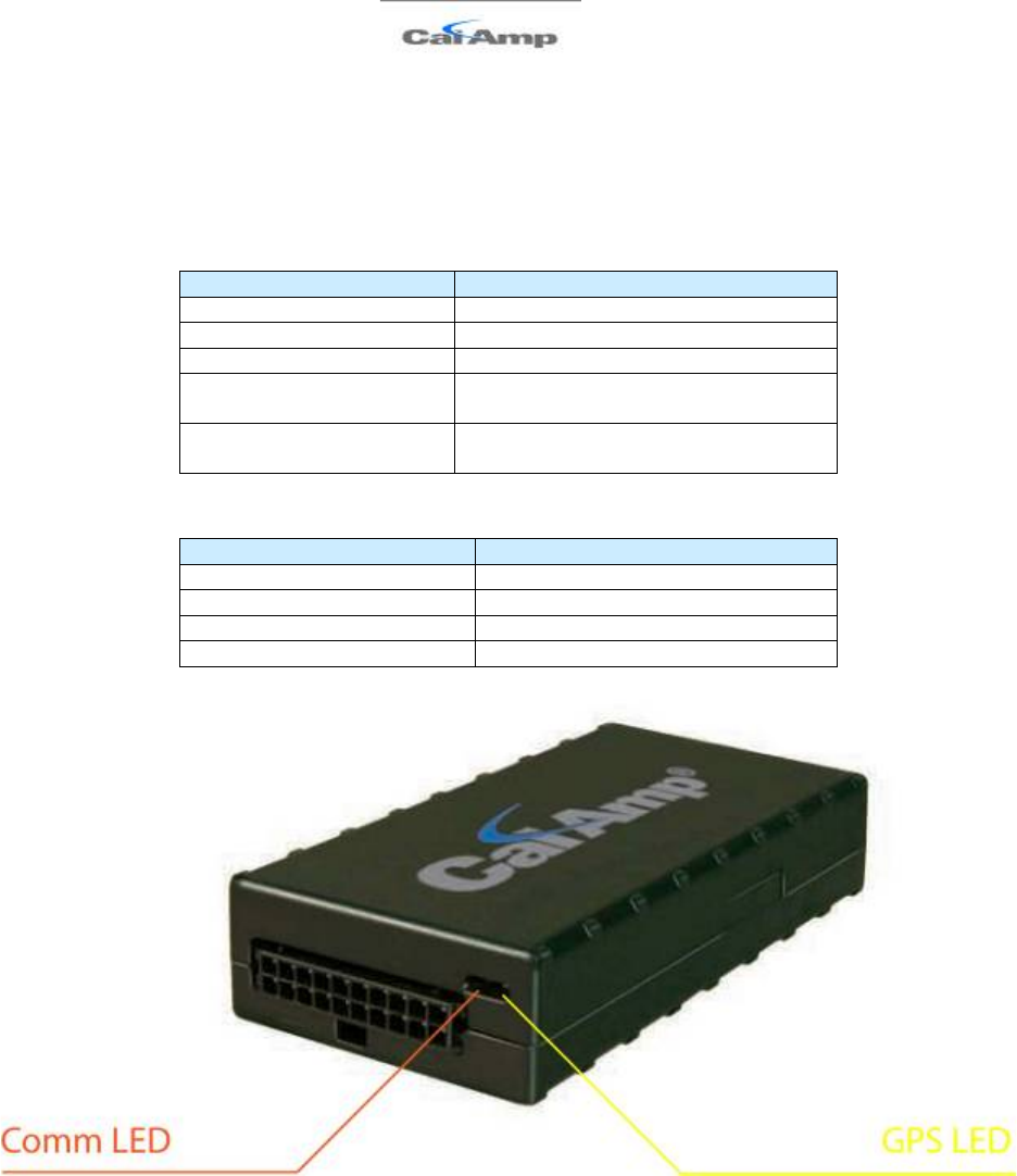
LMU-2x20™ Hardware and Installation Guide
V1.0.10 December 12, 2010
Copyright ©CalAmp DataCom Inc 2010 - 46 - CalAmp Proprietary & Confidential
4.4.4 Status LEDs
The LMU-2x30™ is equipped with two Status LEDs, one for GPS and one for COMM
(wireless network status). The LEDs use the following blink patterns to indicate service:
LED #1 (Comm LED - Orange) Definitions
Condition
LED 1
Modem Off
Off
Comm On - Searching
Slow Blinking
Network Available
Fast Blinking
Registered but no Inbound
Acknowledgement
Alternates from Solid to Fast Blink every
1s
Registered and Received
Inbound Acknowledgement
Solid
LED #2 (GPS LED - Yellow) Definitions
Condition
LED 1
GPS Off
Off
GPS On
Slow Blinking
GPS Time Sync
Fast Blinking
GPS Fix
Solid
Figure 23 - LMU-2x30™ LED Positions

LMU-2x20™ Hardware and Installation Guide
V1.0.10 December 12, 2010
Copyright ©CalAmp DataCom Inc 2010 - 47 - CalAmp Proprietary & Confidential
4.5 Installation Verification
In many cases it is desirable to verify that an installed LMU-2x30™ is working properly.
That is, installers should verify that the GPS and communications functions of the LMU-
2x30™ are working properly before departing the installation site. In more robust cases,
some key configuration settings such as the Inbound Address and URL should also be
verified.
Note that these processes are all based on issuing AT Commands to the LMU-2x30™. It is
expected that installers will have access to a serial port expansion cable and a laptop or PDA
capable of a terminal connection. Alternatively, an SMS message can be sent to an LMU-
2x30™ to obtain its current status.
4.5.1 Comm Verification
Installers should first verify that the LMU-2x30™ has been acquired and has registered to
the wireless network. This may be verified in one of two ways. First, installers may look at
the Comm LED (i.e., the one closest to the SMC antenna connector). If this LED is solid,
then the LMU has registered to the network and established a data session.
If the LED is not visible, then Comm may be verified using an AT Command:
AT$APP COMM?
Depending on the wireless network being used, one of the following responses should
appear:
GSM RSSI:-69 Comm
If any of the responses return Not-Acquired or Not-Registered, the wireless
network operator should be contacted for further troubleshooting.
Please note that it may take several seconds for the LMU-2x30™ to communicate with the
modem and acquire the wireless network.

LMU-2x20™ Hardware and Installation Guide
V1.0.10 December 12, 2010
Copyright ©CalAmp DataCom Inc 2010 - 48 - CalAmp Proprietary & Confidential
4.5.2 GPS Verification
The next step is to verify that the GPS receiver is seeing enough satellites to obtain a valid
GPS position. Again, installers have two choices on how to perform this verification. First,
like the Comm Verification, there is a GPS status LED (i.e., the one closest to the SMA
connector). If this LED is solid, then the LMU has found GPS service.
If the LED is not visible then GPS service may be verified using an AT Command:
AT$APP GPS?
The response should be similar to:
Lat=3304713, Lon=-11727730, Alt=0
Hdg=113 Spd=0 3D-RTIME HDOP=130 nSats=7
Installers are looking for the 3D-RTIME setting along with a valid Lat, Long pair (i.e.
something other than 0). If the GPS receiver does not have a valid lock within 2-3 minutes,
installers should check antenna placement (see the Installation Notes section for placement
suggestions), the antenna connector and that the antenna has a clear view of the sky. For
further troubleshooting, installers should contact CalAmp Support
(M2MSupport@CalAmp.com)

LMU-2x20™ Hardware and Installation Guide
V1.0.10 December 12, 2010
Copyright ©CalAmp DataCom Inc 2010 - 49 - CalAmp Proprietary & Confidential
4.5.3 Inbound Verification
The last item to verify is that the LMU-2x30™ is sending data to the correct server. In
general, this is a two-step process that will need the aid of an observer on the back end. That
is, a technician will have to be logged in so they can monitor data coming into the backend
mapping/vehicle management application.
First, verify that the LMU-2x30™ is using the correct Inbound IP address by using:
AT$APP INBOUND?
The response should be similar to:
INBOUND LMD
INBOUND 0 ADDR ddd.ddd.ddd.ddd:ppppp *
INBOUND 0 URL myURL.myCompany.com
INBOUND 1 ADDR 0.0.0.0:20500
INBOUND 1 URL
INBOUND 2 ADDR 0.0.0.0:20500
INBOUND 3 ADDR 0.0.0.0:20500
The installer will need to verify with a backend technician that the, URL
(myURL.myCompany.com ), IP address (ddd.ddd.ddd.ddd) and port (<ppppp>) are correct.
The second step is to verify that the LMU-2x30™ is sending data. The best way to do this is
to force the LMU-2x30™ to send in an unacknowledged Event Report (i.e., its current GPS
location) with the following command:
AT$APP PEG SUNRPT 255
The LMU-2x30™ will respond with: OK
The backend monitor must then be contacted to confirm that they received an Event Report
with Event Code 255.
Assuming that all three sections have passed, the installation can be considered to be
complete.

LMU-2x20™ Hardware and Installation Guide
V1.0.10 December 12, 2010
Copyright ©CalAmp DataCom Inc 2010 - 50 - CalAmp Proprietary & Confidential
4.5.4 Verification via SMS
The current Comm, GPS and Inbound status of a GSM LMU can be obtained via SMS
provided you have access to an SMS capable phone or PDA.
Using your handset, send the following SMS Message to the LMU:
!R0
Within a few minutes, the LMU should return a response in the following format:
APP: <App ID> <Firmware Version>
COM:<RSSI> [./d/D][./a/A][./L][IP address] [<APN>]
GPS:[Antenna <Short/Open/Off>] | [No Time Sync] |
[<FixStatus> <Sat Count>]
INP:<inputs states> <vehicle voltage>
MID:<mobile ID> <mobile ID type>
INB:<inbound IP address>:<inbound port> <Inbound
Protocol (LMD/LMX)>
• APP:
o <App ID>:
The Application ID value of the LMU indicating the host platform and the
wireless networking technology of the LMU.
o <Firmware Version>:
The current firmware version in use by the LMU
• COM:
o <RSSI>:
This is the signal strength the wireless modem sees from the network. In
general the LMU is at least scanning for the network if the RSSI is not -113.
o [./d/D]:
If the character ‘D’ is present, it indicates the LMU had a data session
established when it responded to the status request. For the 8-Bit product line
an upper case ‘D’ indicates both the Inbound and Maintenance sockets are
ready. The lower case ‘d’ indicates that only the Maintenance socket is ready.
A ‘.’ indicates no sockets are ready.
o [./a/A]:
This field indicates if the LMU has received an Acknowledgement from the
Inbound server. This field will be empty if the LMU has never received an
ACK.The lower case ‘a’ will be present if it has received an ACK since the last
cold boot (i.e. power cycle) but not the last warm boot (App Restart or Sleep).
The upper case ‘A’ will be present if the LMU has received an ACK since the
last warm boot. A ‘.’ Indicates no acknowledgement has been received.

LMU-2x20™ Hardware and Installation Guide
V1.0.10 December 12, 2010
Copyright ©CalAmp DataCom Inc 2010 - 51 - CalAmp Proprietary & Confidential
o [./L]:
This field indicates if the LMU’s log is currently active. An ‘L’ indicates that
the log is currently in use (i.e. one or more records have been stored) where a
‘.’ indicates the log is inactive.
o [IP Address]:
This is an optional field if and is only present if the LMU has established a
valid data session. This field will contain the current IP address of the LMU as
assigned by the wireless network. Note that if you see a value of 192.168.0.0,
this is an indication that the LMU has not been able to establish a data session.
o [<APN>]
The current Access Point Name in use by a GSM LMU.
• GPS:
o [Antenna <Short/Open/Off>]:
This field, if present, indicates a problem with the LMU’s GPS antenna. A
value of Short indicates that the antenna cable has likely been crushed. A value
of Open indicates that the antenna cable is either cut or disconnected. A value
of Off indicates that the LMU’ GPS receiver is off.
o [No Time Sync]:
If this field is present, it indicates that the LMU’s GPS receiver has not been
able to find even a single GPS satellite. This would likely been seen in
conjunction with the above antenna error, or if the LMU GPS antenna is
otherwise blocked5.
o [<FixStatus> <Sat Count>]:
If these fields are present it indicates that the LMU has, or had a valid GPS
solution. The <Sat Count> field indicates how many GPS satellites are
currently in use by the LMU. The <FixStatus> field indicates the type of fix.
The Fix Status types are detailed in the LM Direct Reference Guide.
• INP:
o <input states>:
This field details the current state of each of the LMU’s discreet inputs. This
field is always 8 characters long. The left most character represents the state of
input 7 where the right most represents the state of input 0 (i.e. the ignition).
A value of 1 indicates the input is currently in the high state. A value of 0
indicates it is currently in the low state.
o <vehicle voltage>:
This field will contain the current reading of the LMU’s internal A/D. This
will be the supply voltage provided to the LMU in mV.
• MID:
o <mobile ID>:
This will be the current mobile ID in use by the LMU.
5 For example you may see this if the vehicle is in a garage when the LMU is powered up.

LMU-2x20™ Hardware and Installation Guide
V1.0.10 December 12, 2010
Copyright ©CalAmp DataCom Inc 2010 - 52 - CalAmp Proprietary & Confidential
o <mobile ID type>:
This will be the type of Mobile ID in use by the LMU. The available types are,
Off, ESN, IMEI, IMSI, USER, MIN and IP ADDRESS.
• INB:
o <inbound IP address>:
This is the current IP address in use by the LMU. This value should match the
IP address of your LM Direct™ server.
o <inbound port>:
This is the current UDP port the LMU will use to deliver its LM Direct™
data. This value should match UDP port you are using on your LM Direct™
server. It is typically 20500.
o <Inbound Protocol (LMD/LMX)>:
This is the current UDP/IP messaging protocol in use by the LMU. In general
it should be LMD.
Example GSM Response
APP:081 8.3d
COM:0
GPS:No Time Sync
INP:11100111 13.7V
MID:4141000100 ESN
INB:207.7.101.227:20500 LMD
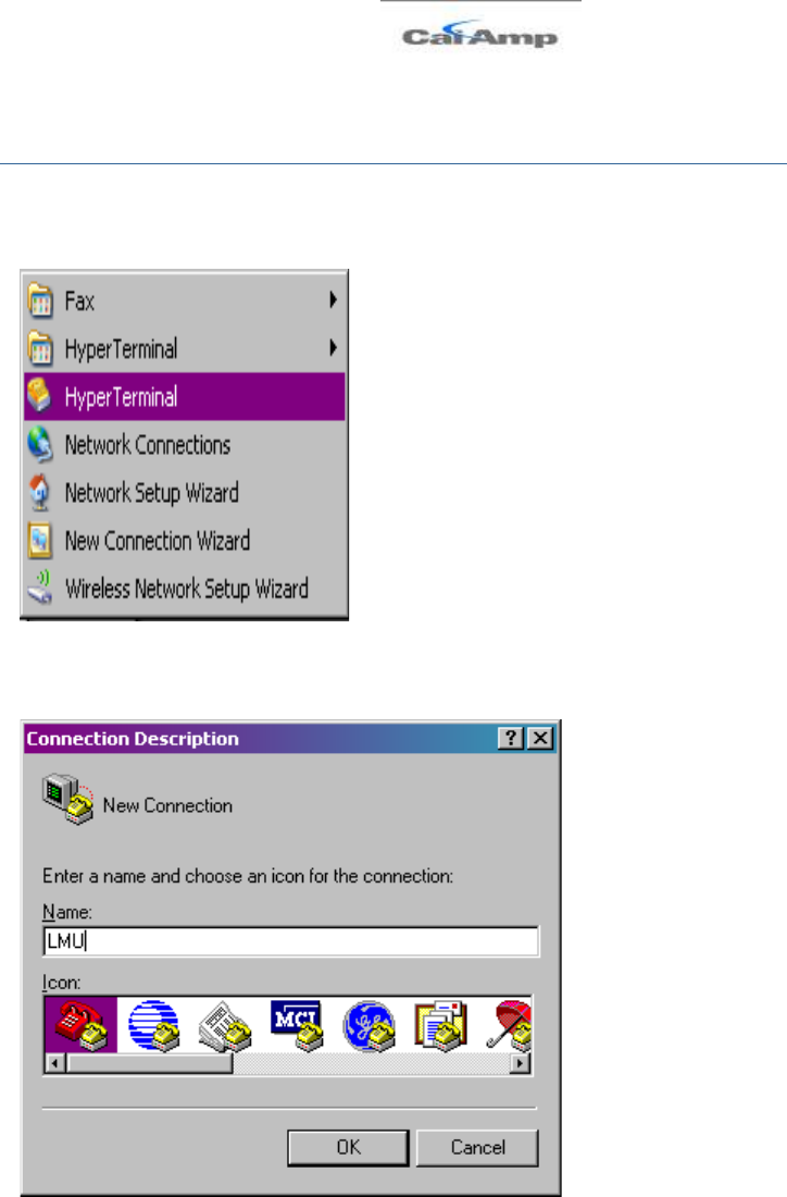
LMU-2x20™ Hardware and Installation Guide
V1.0.10 December 12, 2010
Copyright ©CalAmp DataCom Inc 2010 - 53 - CalAmp Proprietary & Confidential
Appendix A - HyperTerminal Configuration
Click the Start button and go to Programs, Accessories and Communications.
Click the Hyper Terminal icon.
This should display a new connection wizard.
Name the connection LMU
Click OK.
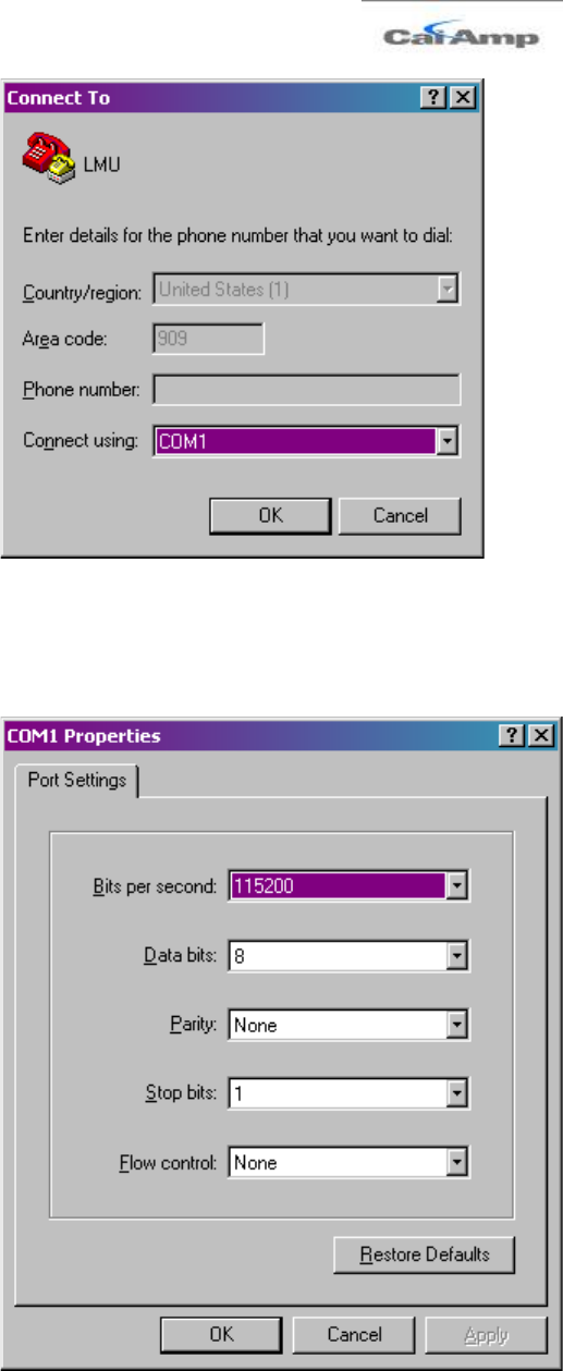
LMU-2x20™ Hardware and Installation Guide
V1.0.10 December 12, 2010
Copyright ©CalAmp DataCom Inc 2010 - 54 - CalAmp Proprietary & Confidential
Change Connect using field to read Direct to ComX, where X is the Com port that the LMU
is attached to.
Click OK.
Change Bits per second to read 115200.
Click OK.
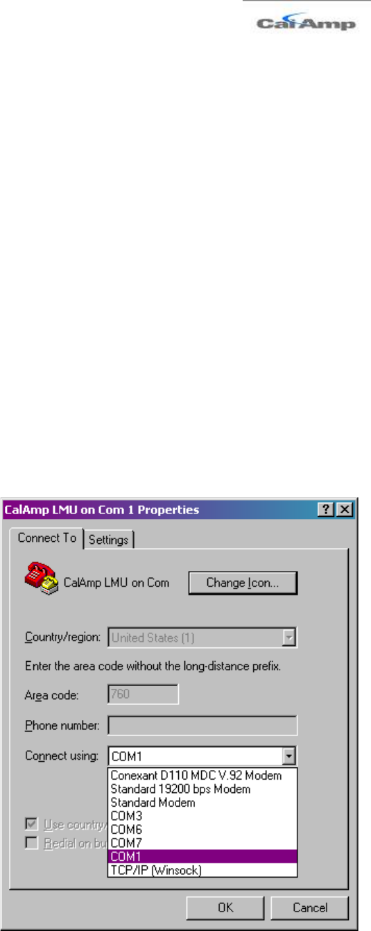
LMU-2x20™ Hardware and Installation Guide
V1.0.10 December 12, 2010
Copyright ©CalAmp DataCom Inc 2010 - 55 - CalAmp Proprietary & Confidential
The wizard should now close and a cursor should appear in the main HyperTerminal
window. It is a good idea to verify that communications are established with the LMU. This
can be done by issuing the following AT Command:
ATI0
A response similar to the following should appear:
APP:LMU,001 V8.0b (Sep 26 2007 18:10:32)
PIC:TIM S/N 4130000200
GPS:UBLOX-00040001 -5.00 Jan 09 2006 12:00:00
Radio:SIEMENS TC65-REVISION 02.000
If another response appears it is a good chance that HyperTerminal is connected to the
wrong Com Port. The com port setting can be changed by the following sequence.
Click the Call menu then select Disconnect.
From the File menu click Properties.
The Com Port can be changed by altering the Connect Using entry and clicking OK.

LMU-2x20™ Hardware and Installation Guide
V1.0.10 December 12, 2010
Copyright ©CalAmp DataCom Inc 2010 - 56 - CalAmp Proprietary & Confidential
To reconnect HyperTerminal to the LMU select Call from the Call menu.

LMU-2x20™ Hardware and Installation Guide
V1.0.10 December 12, 2010
Copyright ©CalAmp DataCom Inc 2010 - 57 - CalAmp Proprietary & Confidential
Appendix B - Windows Vista - Putty Setup
Microsoft stopped including the HyperTerminal program as part of its offering with
Windows Vista. As a result you will need to find an alternate program to communicate
directly with the LMU. One option is to purchase HyperTerminal from Hilgraeve
(http://www.hilgraeve.com/hyperterminal.html).
Alternatively you can use a terminal emulation program such as PuTTY.
(http://www.chiark.greenend.org.uk/~sgtatham/putty/).
The following instructions describe how to configure PuTTY for use with the CalAmp
LMU.
Download and save the PuTTY.exe file to your PC.
1. Launch the PuTTY.exe file
2. Change the Connection type to Serial
3. Change the Speed to 115200
4. Change the Serial Line field to COM<x> where <x> is the port the LMU is
connected to.
5. In the Saved Sessions field enter CalAmp LMU
6. Click Save
7. Make sure the LMU is connected and powered on and then click Open
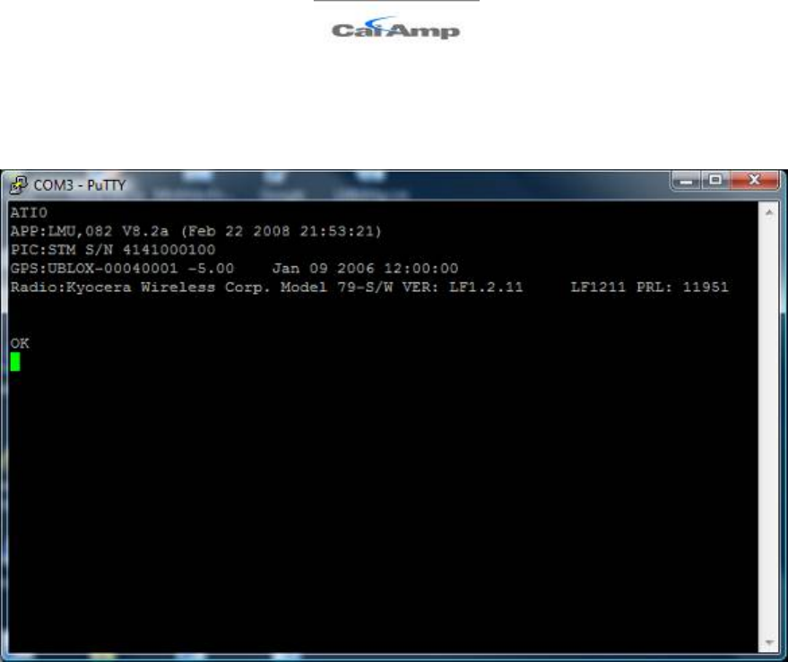
LMU-2x20™ Hardware and Installation Guide
V1.0.10 December 12, 2010
Copyright ©CalAmp DataCom Inc 2010 - 58 - CalAmp Proprietary & Confidential
8. To test the connection, enter the AT Command ATI0. (Note, if you cannot see what
you are typing, enter a second AT Command of ATE1
You should see a response similar to the following: