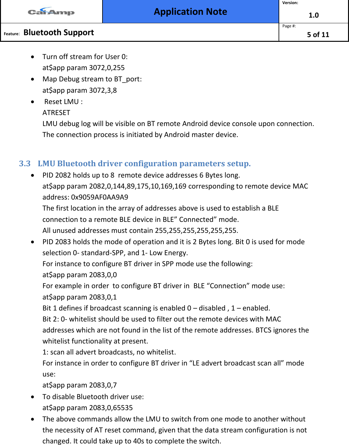
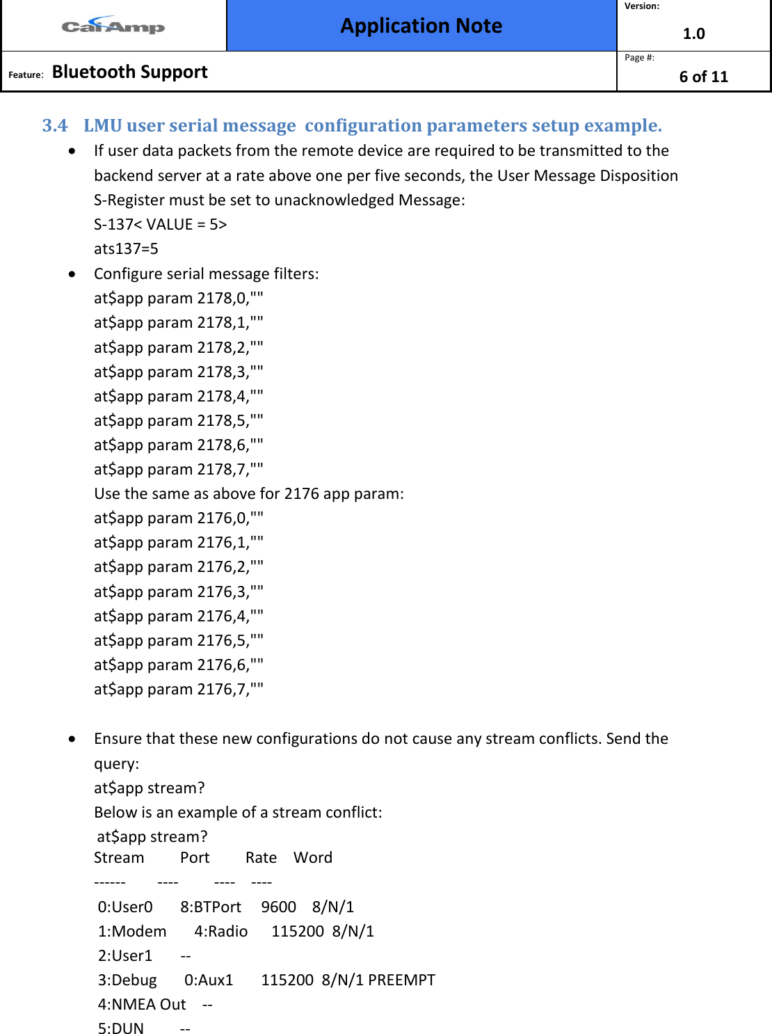
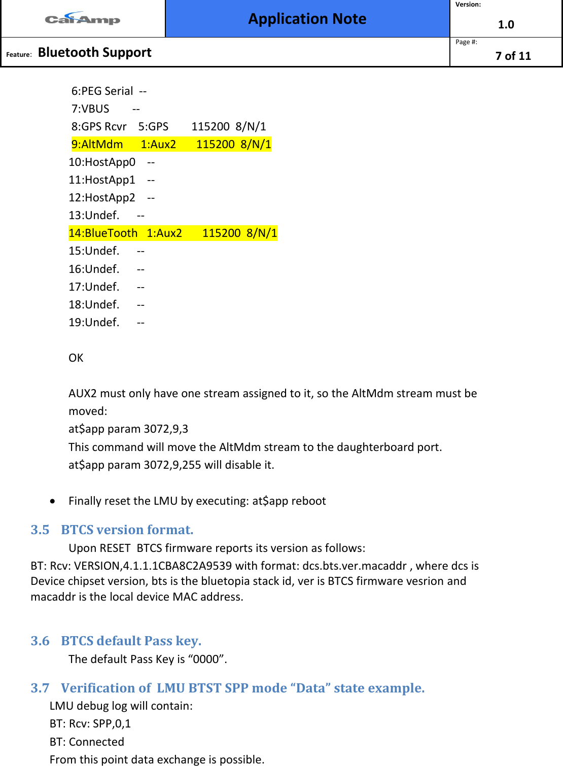
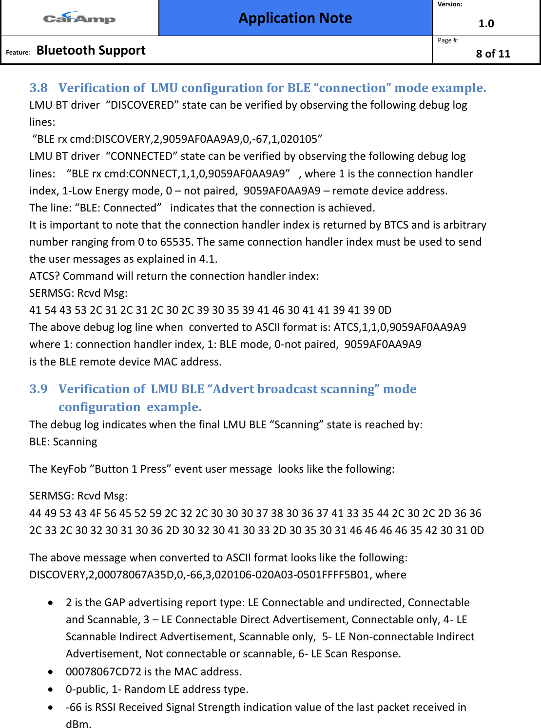
CalAmp 3030CBT Location Messaging Unit User Manual Configuration App Note

CalAmp Location Messaging Unit Configuration App Note

Contents

User Manual I

 Application Note Version: 1.0  Feature:   Bluetooth Support  Page #: 1 of 11    LMU Bluetooth Chipset Application Note Boris Velev
 Application Note Version: 1.0  Feature:   Bluetooth Support  Page #: 2 of 11   1 Introduction ........................................................................................................................ 3 2 Description .......................................................................................................................... 3 3 Setup ................................................................................................................................... 4 3.1 LMU BT LE driver streams and serial port configuration parameters setup example.  4 3.2 LMU BTST SPP driver streams and serial port configuration parameters setup example. ................................................................................................................................. 4 3.3 LMU Bluetooth driver configuration parameters setup. ............................................ 5 3.4 LMU user serial message  configuration parameters setup example......................... 6 3.5 BTCS version format. ................................................................................................... 7 3.6 BTCS default Pass key. ................................................................................................. 7 3.7 Verification of  LMU BTST SPP mode “Data” state example. ...................................... 7 3.8 Verification of  LMU configuration for BLE “connection” mode example. ................. 8 3.9 Verification of  LMU BLE “Advert broadcast scanning” mode configuration  example. ................................................................................................................................. 8 4 Usage .................................................................................................................................. 9 4.1 Demonstration of LMU BT SPP mode. ........................................................................ 9 4.2 Demonstration of BLE “connection” mode based remote temperature sensor device. .................................................................................................................................... 9 4.3 Demonstration of BLE “broadcast scanning” mode based remote KeyFob DriverID device. .................................................................................................................................. 11
 Application Note Version: 1.0  Feature:   Bluetooth Support  Page #: 3 of 11     1 Introduction This application note documents the use of Bluetooth chipset device based on TI MSP430F5438A microcontroller and CC2564 RF processor. The BTCS device has Bluetooth LE4.0 dual mode capabilities. The firmware is based on Stonestreet One Bluetopia protocol stack. The document uses as an example the Texas Instruments CC 2541 Sensor Tag with the purpose of reading the temperature from TI TMP006 temperature sensor. A “KeyFob” device which broadcasts “Button xx press” events together with “battery charge state as percentage“ information is used as another example.  2 Description  The BTCS device is connected to a LMU serial port. The BTCS unit supports Bluetooth SPP mode of operation. BTCS plays a server slave device which upon connection with a Remote Bluetooth client master device can exchange data. There are two Bluetooth low energy (BLE) modes of operation: “Connection” based and an “Advert Broadcast Scanning” mode. In “Connection” mode, the LMU firmware starts the discovery process of all BLE remote devices. If a match is found based on the remote address stored as an “APP PARAM 2082”, the discovery sequence is ended and the connection process starts. Upon the reception of “CONNECTED_OK” event, the user will be able to send setup commands to the remote device, and consequently receive the sensor data.  In “Advert Broadcast scanning” mode BT driver simply receives the broadcast advertisements from all remote BLE devices.  The block diagram is  presented in Figure 1 below.
 Application Note Version: 1.0  Feature:   Bluetooth Support  Page #: 4 of 11    Figure 1 3 Setup  3.1 LMU BT LE driver streams and serial port configuration parameters setup example.   Map debug stream to Aux1 port. AT$APP PARAM 3072,3,0  Bluetooth stream to AUX 2. AT$APP PARAM 3072,14,1  A Bluetooth stream baud rate set to 115200 AT$APP PARAM 3073,14,12  A Bluetooth stream set to 8, n, 1 AT$APP PARAM 3074,14,3  User0 Stream to Bluetooth Port AT$APP PARAM 3072,0,8  3.2 LMU BTST SPP driver streams and serial port configuration parameters setup example.   LMU BT driver SPP mode setup: at$app param 2083,0,0  User Serial  Tx Data BT STREAM BLE  “AT cmd” Parser BT_DRV  BT_ Sensor BT_ Sensor BT_DRV  BT STREAM User Serial Rx  Data BTCS BTCS SPP
 Application Note Version: 1.0  Feature:   Bluetooth Support  Page #: 5 of 11    Turn off stream for User 0:  at$app param 3072,0,255  Map Debug stream to BT_port:  at$app param 3072,3,8   Reset LMU : ATRESET LMU debug log will be visible on BT remote Android device console upon connection. The connection process is initiated by Android master device.  3.3 LMU Bluetooth driver configuration parameters setup.   PID 2082 holds up to 8  remote device addresses 6 Bytes long.  at$app param 2082,0,144,89,175,10,169,169 corresponding to remote device MAC  address: 0x9059AF0AA9A9 The first location in the array of addresses above is used to establish a BLE connection to a remote BLE device in BLE” Connected” mode. All unused addresses must contain 255,255,255,255,255,255.  PID 2083 holds the mode of operation and it is 2 Bytes long. Bit 0 is used for mode selection 0- standard-SPP, and 1- Low Energy. For instance to configure BT driver in SPP mode use the following: at$app param 2083,0,0 For example in order  to configure BT driver in  BLE “Connection” mode use: at$app param 2083,0,1 Bit 1 defines if broadcast scanning is enabled 0 – disabled , 1 – enabled. Bit 2: 0- whitelist should be used to filter out the remote devices with MAC addresses which are not found in the list of the remote addresses. BTCS ignores the whitelist functionality at present. 1: scan all advert broadcasts, no whitelist. For instance in order to configure BT driver in “LE advert broadcast scan all” mode use: at$app param 2083,0,7  To disable Bluetooth driver use: at$app param 2083,0,65535  The above commands allow the LMU to switch from one mode to another without the necessity of AT reset command, given that the data stream configuration is not changed. It could take up to 40s to complete the switch.
 Application Note Version: 1.0  Feature:   Bluetooth Support  Page #: 6 of 11   3.4 LMU user serial message  configuration parameters setup example.   If user data packets from the remote device are required to be transmitted to the backend server at a rate above one per five seconds, the User Message Disposition S-Register must be set to unacknowledged Message: S-137< VALUE = 5> ats137=5  Configure serial message filters: at$app param 2178,0,"" at$app param 2178,1,"" at$app param 2178,2,"" at$app param 2178,3,"" at$app param 2178,4,"" at$app param 2178,5,"" at$app param 2178,6,"" at$app param 2178,7,"" Use the same as above for 2176 app param: at$app param 2176,0,"" at$app param 2176,1,"" at$app param 2176,2,"" at$app param 2176,3,"" at$app param 2176,4,"" at$app param 2176,5,"" at$app param 2176,6,"" at$app param 2176,7,""   Ensure that these new configurations do not cause any stream conflicts. Send the query: at$app stream? Below is an example of a stream conflict:               at$app stream? Stream         Port         Rate    Word ------        ----         ----    ----  0:User0       8:BTPort     9600    8/N/1  1:Modem       4:Radio      115200  8/N/1  2:User1       --  3:Debug       0:Aux1       115200  8/N/1 PREEMPT  4:NMEA Out    --  5:DUN         --
 Application Note Version: 1.0  Feature:   Bluetooth Support  Page #: 7 of 11    6:PEG Serial  --  7:VBUS        --  8:GPS Rcvr    5:GPS        115200  8/N/1  9:AltMdm      1:Aux2       115200  8/N/1 10:HostApp0    -- 11:HostApp1    -- 12:HostApp2    -- 13:Undef.      -- 14:BlueTooth   1:Aux2       115200  8/N/1 15:Undef.      -- 16:Undef.      -- 17:Undef.      -- 18:Undef.      -- 19:Undef.      --  OK  AUX2 must only have one stream assigned to it, so the AltMdm stream must be moved: at$app param 3072,9,3 This command will move the AltMdm stream to the daughterboard port. at$app param 3072,9,255 will disable it.   Finally reset the LMU by executing: at$app reboot 3.5 BTCS version format.  Upon RESET  BTCS firmware reports its version as follows: BT: Rcv: VERSION,4.1.1.1CBA8C2A9539 with format: dcs.bts.ver.macaddr , where dcs is Device chipset version, bts is the bluetopia stack id, ver is BTCS firmware vesrion and macaddr is the local device MAC address.  3.6 BTCS default Pass key.  The default Pass Key is “0000”. 3.7 Verification of  LMU BTST SPP mode “Data” state example.  LMU debug log will contain: BT: Rcv: SPP,0,1 BT: Connected From this point data exchange is possible.
 Application Note Version: 1.0  Feature:   Bluetooth Support  Page #: 8 of 11   3.8 Verification of  LMU configuration for BLE “connection” mode example.  LMU BT driver  “DISCOVERED” state can be verified by observing the following debug log lines:                                                                                                                                         “BLE rx cmd:DISCOVERY,2,9059AF0AA9A9,0,-67,1,020105”                                                                          LMU BT driver  “CONNECTED” state can be verified by observing the following debug log lines:    “BLE rx cmd:CONNECT,1,1,0,9059AF0AA9A9”   , where 1 is the connection handler index, 1-Low Energy mode, 0 – not paired,  9059AF0AA9A9 – remote device address.      The line: “BLE: Connected”   indicates that the connection is achieved.                              It is important to note that the connection handler index is returned by BTCS and is arbitrary number ranging from 0 to 65535. The same connection handler index must be used to send the user messages as explained in 4.1.  ATCS? Command will return the connection handler index: SERMSG: Rcvd Msg:  41 54 43 53 2C 31 2C 31 2C 30 2C 39 30 35 39 41 46 30 41 41 39 41 39 0D  The above debug log line when  converted to ASCII format is: ATCS,1,1,0,9059AF0AA9A9 where 1: connection handler index, 1: BLE mode, 0-not paired,  9059AF0AA9A9 is the BLE remote device MAC address. 3.9 Verification of  LMU BLE “Advert broadcast scanning” mode configuration  example.  The debug log indicates when the final LMU BLE “Scanning” state is reached by:                BLE: Scanning The KeyFob “Button 1 Press” event user message  looks like the following: SERMSG: Rcvd Msg:                                                                                                                               44 49 53 43 4F 56 45 52 59 2C 32 2C 30 30 30 37 38 30 36 37 41 33 35 44 2C 30 2C 2D 36 36 2C 33 2C 30 32 30 31 30 36 2D 30 32 30 41 30 33 2D 30 35 30 31 46 46 46 46 35 42 30 31 0D The above message when converted to ASCII format looks like the following: DISCOVERY,2,00078067A35D,0,-66,3,020106-020A03-0501FFFF5B01, where   2 is the GAP advertising report type: LE Connectable and undirected, Connectable and Scannable, 3 – LE Connectable Direct Advertisement, Connectable only, 4- LE Scannable Indirect Advertisement, Scannable only,  5- LE Non-connectable Indirect Advertisement, Not connectable or scannable, 6- LE Scan Response.                    00078067CD72 is the MAC address.                                                                                                   0-public, 1- Random LE address type.                                                                                                                           -66 is RSSI Received Signal Strength indication value of the last packet received in dBm.
 Application Note Version: 1.0  Feature:   Bluetooth Support  Page #: 9 of 11    3 is number of advertising report data entries.  02 is the first advertisement report data length in Bytes.  01 is the first report advertisement type.  06 is the first report advertising data byte.  020A03 is the second AD report.  0501FFFF5B01 is the third AD report.  The user data is in the third AD report-5B: 91% battery charge remaining, 01 :Button 1 is pressed. 4 Usage 4.1 Demonstration of LMU BT SPP mode.  Follow the instructions in 3.2. Android Bluetooth SPP application  starts the process of connection with BTCS and upon completion all LMU debug log data will be visible in Android device console. All Android input keyboard messages  ending with ‘CR’  will be visible in its console. 4.2 Demonstration of BLE “connection” mode based remote temperature sensor device.  “GPSTRAX” server is used to send User0 messages. Select route: 0 and ID: 0 as shown in Figure 2 below   Figure 2
 Application Note Version: 1.0  Feature:   Bluetooth Support  Page #: 10 of 11   There is a limitation of the length of the command which has to be less than 32 BYTES. 4.2.1 Send command “Enable notifications on Temperature sensor attribute profile”. Populate the “Data” field in Figure 2 with the hexadecimal representation of ATGW,1,38,2,1 - 0x415447572C312C33382C322C31.                                                                Where ATGW is the BTCS  API for  characteristic “WRITE” (GATT WRITE). It is used to write the characteristic value or descriptor from a server when the attribute handle of the characteristic value is known. 1 is the BTCS  connection handler, and can be an arbitrary number.  Use ATCS command to get the correct connection handler index as explained in 3.6. The rest of the command is “SensorTag” temperature sensor specific.  38 is the SensorTag board temperature sensor “Notification settings” handler index. 2 is the “Notifications” configuration parameter byte length. The last field is the parameter value - 1 stands for “Turn ON” operation , 0 for “Turn OFF”. 4.2.2 Send command “Start temperature conversion”. Populate the “Data” field in Figure 2 with the hexadecimal representation of ATGW,1,41,1,1 - 0x415447572C312C34312C312C31 The command fields description is the same as 4.1. 4.2.3 Observe the GPSTRAX server User 0 temperature data. 474154545F56414C2C312C303033372C312C342C44394646313030430D In LMU debug log the same message can be observed:                                                                        SERMSG: RcvMsg:              474154545F56414C2C312C303033372C312C342C44394646313030430D                  Converted to ASCII format the same message is:   GATT_VAL,1,37,1,4,D9FF100C0D, where   1 corresponds to the connection ID ranging from 1 to 65535,                                                                              37 corresponds to the GATT characteristic handler index specific to TI temperature sensor,  1 is  GATT notification,                                                                                                                                                                                              4 is  data length in Bytes,                                      D9FF100C0D  represents the sensor data.                                                                                       The data colored in yellow represent the temperature, where 0xD9 is the lowest significant byte of the Object temperature, 0xFF- MSB of object temperature, 0x10 – LSB of the ambient temperature, 0x0C – MSB of the ambient temperature. 4.2.4 Disable BLE sensor “notifications”. Populate the data field in Figure 2 with the hexadecimal representation of  ATGW,1,38,2,0 - 0x415447572C312C33382C322C30
 Application Note Version: 1.0  Feature:   Bluetooth Support  Page #: 11 of 11   4.2.5 Send command “Stop” temperature conversion. Populate the data field in Figure 2 with the hexadecimal representation of  ATGW,1,41,1,0 - 0x415447572C312C34312C312C30 4.2.6 “GPSTRAX” server report contains temperature sensor data.  10/22/2013 20:21:45 4861000011 36.7926 0 0 0A474154545F56414C2C312C303033372C312C342C43444646463430420D  4.3 Demonstration of BLE “broadcast scanning” mode based remote KeyFob DriverID device.  The GPSTRAX server report will contain the following User0 messages: 0A444953434F564552592C322C3030303738303637434437322C302C2D35352C332C3032303130362D3032304130332D3035303146464646353430310D Which converted into ASCII representing “Button1 press” event: DISCOVERY,2,00078067CD72,0,-55,3,020106-020A03-0501FFFF5401  The user payload content description is given in 3.3. The Raw message type 4 is presented below: 830548610000110101000415A25295086652950866EA11DA4C682ABBA7000000000000000000AE0B020001FFCD4F09DD000000003D0A444953434F564552592C322C3030303738303637434437322C302C2D35352C332C3032303130362D3032304130332D3035303146464646353430310D

Navigation menu