CalAmp 4530HE Cell Module User Manual TTU4530 Installation Guide
CalAmp Cell Module TTU4530 Installation Guide
UserManual.wiki
>
CalAmp
>
4530HE User Manual
User Manual
Navigation menu
Upload a User Manual
Namespaces
Wiki Guide
HTML
PDF
Info
Views
User Manual
Discussion / Help
Navigation
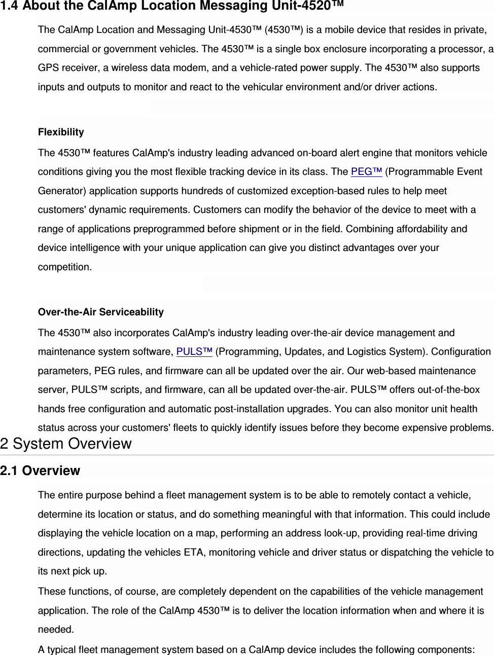
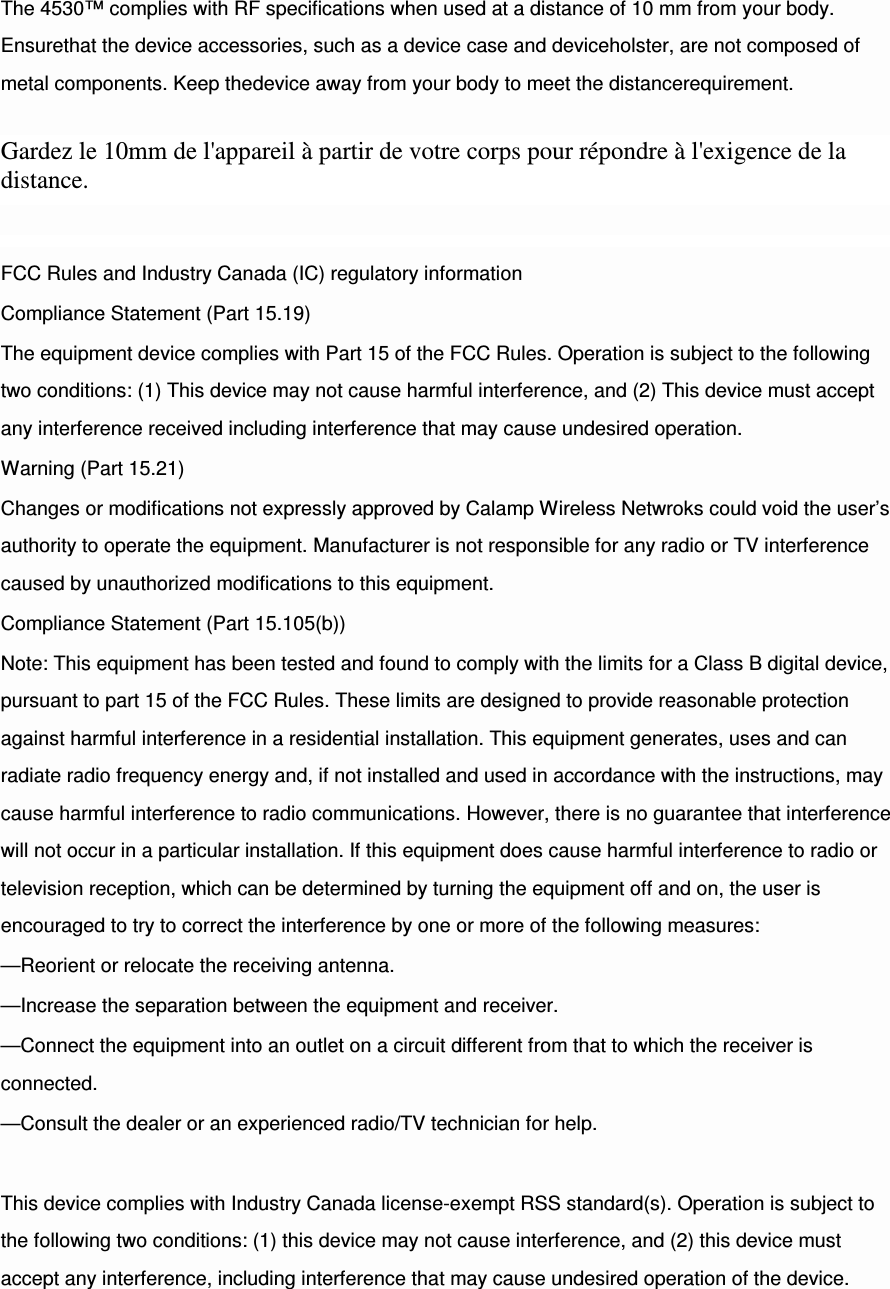
![2.2 Component Descriptions 2.2.1 Wireless Data Network The Wireless Data Network provides the information bridge between the LM Direct™ server and the 4530™. Wireless data networks can take a variety of forms, such as cellular networks, satellite systems or local area networks. Contact the CalAmp sales team for the networks available to the 4530™. 2.2.2 4530™ The 4530™ is responsible for delivering the location and status information when and where it is needed. Data requests mainly come from the following sources: PEG™ script within the 4530™ A location or status request from the LM Direct™ server A location or status request from LMU Manager An SMS request made from a mobile device such as a customer’s cell-phone In some cases, it is necessary to run an application in the vehicle while it is being tracked by the backend software. Such examples could include instant messaging between vehicles or a central office, in-vehicle mapping or driving directions, email or database access. In most of these cases you will be using the 4530™ as a wireless modem as well as a vehicle-location device. ]2.2.3 LM Direct™ Server LM Direct™ is a CalAmp proprietary message interface specification detailing the various messages and their contents the 4530™ is capable of sending and receiving. This interface allows System Integrators to communicate directly with 4530's™. Please refer to the LM Direct Reference Guide for details. 2.2.4 Backend Software Backend software is a customer provided software application. Regardless of its purpose, one of its primary functions is to parse and present data obtained from the LM Direct™ server. This allows the application to do any of the following: Display location database on reports received from the 4530™ in a variety of formats](https://usermanual.wiki/CalAmp/4530HE/User-Guide-2969319-Page-5.png)
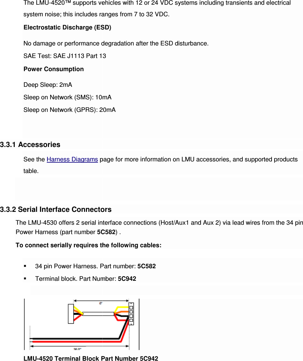
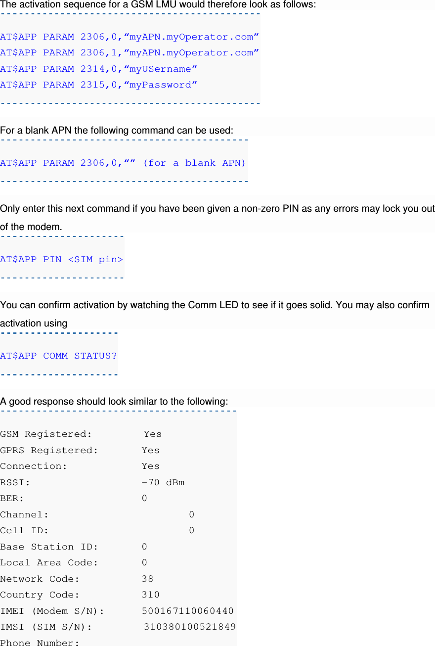
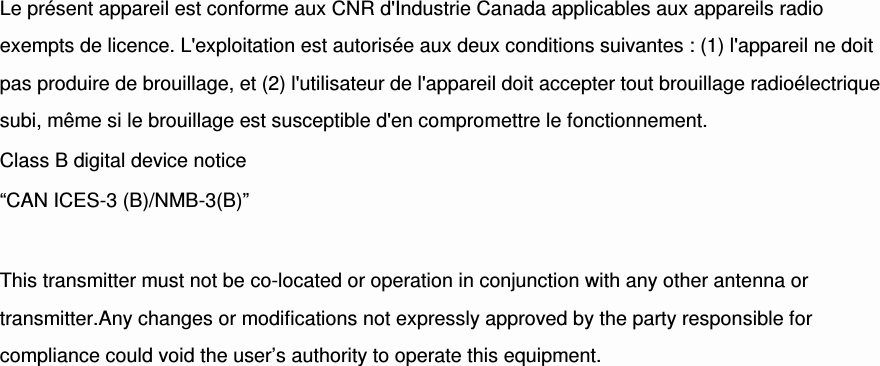
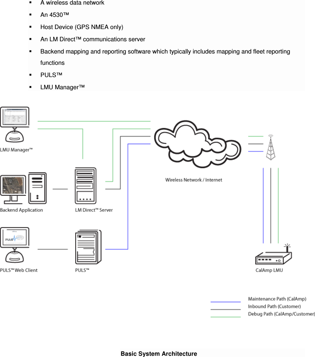
![Channel: 0 Band:Side: 800:B Base Station ID: 0 Network ID: 0 System ID: 4 ESN (Modem S/N: 2676319948 [9F8566CC] Phone Number: 1234567890 IMSI: 310001234567890 CarrierConfig: 5 Note that the Phone Number should match the MDN value the carrier gave you. The last 10 digits of the IMSI field should match the MIN/MSID value they gave you. For devices that have had previous activations, an Over-The-Air activation process may be manually started using a single AT Command: AT$APP MODEM UPDATE This command is also used to initiate an Over-The-Air PRL Update for devices that are already provisioned. Users may also force a reactivation with the command: AT$APP MODEM ACTIVATE Keep in mind, however, this may cause the modem to lose its credentials and become unable to register to the network. 4.5.2 Activating a CDMA LMU-4530™ – Sprint Activating an LMU-4530™ on the Sprint CDMA network is identical to activating on the Verizon network. 1. Power on the LMU-4530™, making sure you can observe the behavior of the Comm LED. 2. Wait until the Comm LED turns solid. This could take up to 5 minutes. 3. If after 5 minutes you observe that the Comm LED transitions from a slow blink to a fast blink several times (i.e. more than twice) you will need to contact Sprint for further support on account activation..](https://usermanual.wiki/CalAmp/4530HE/User-Guide-2969319-Page-20.png)
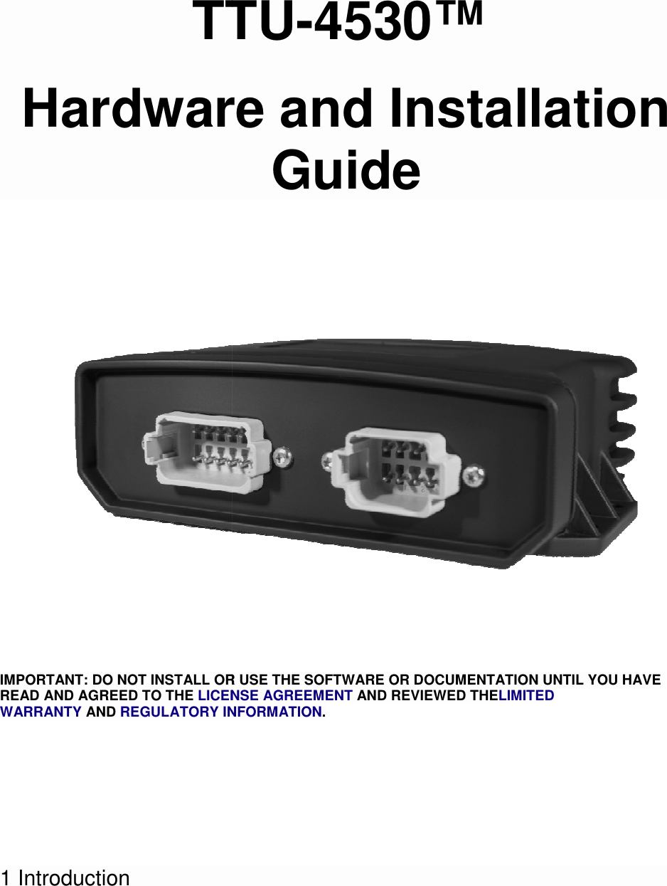
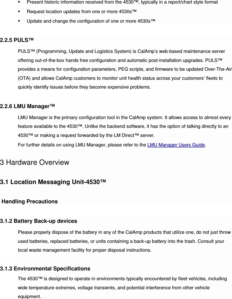
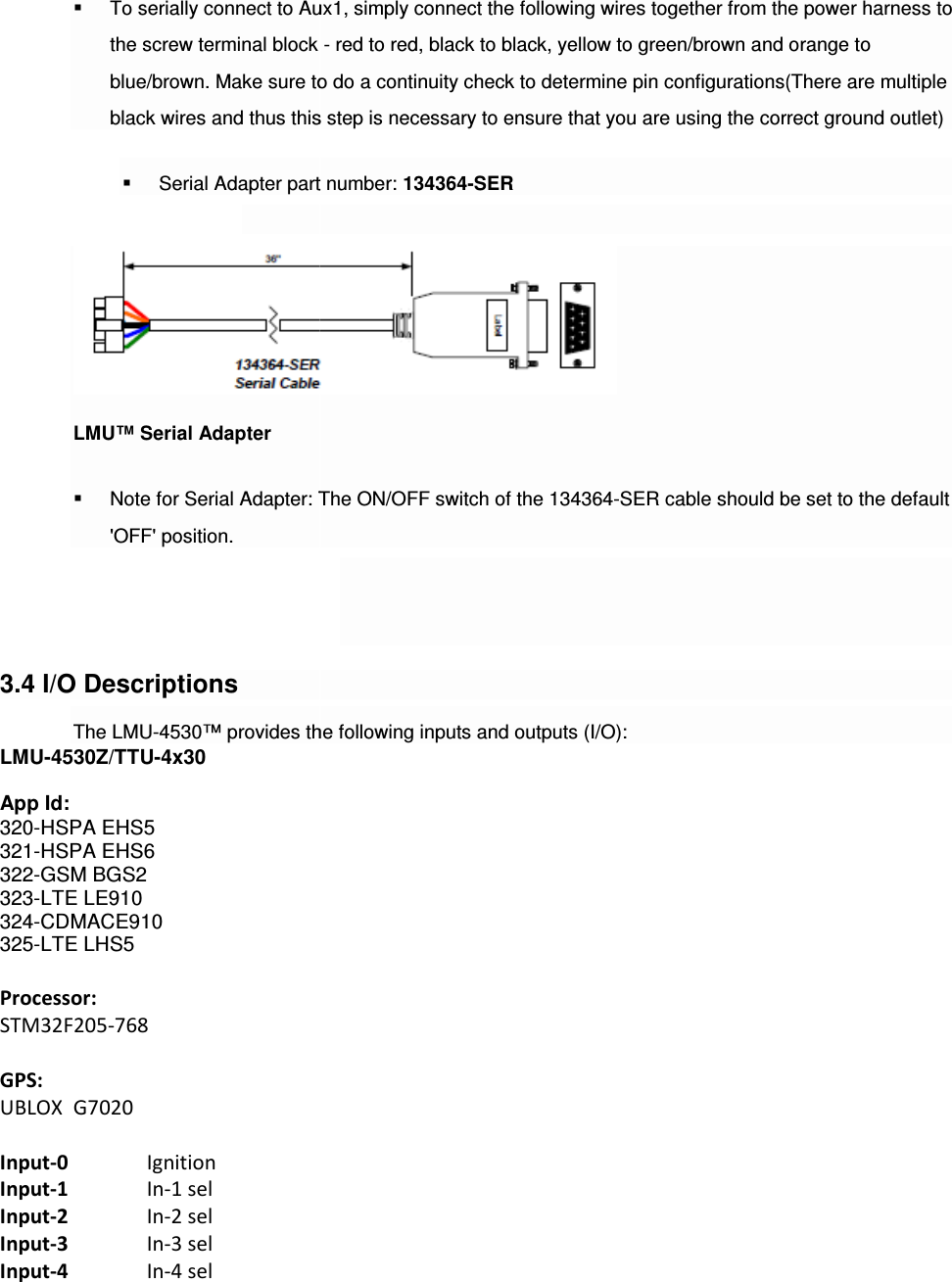
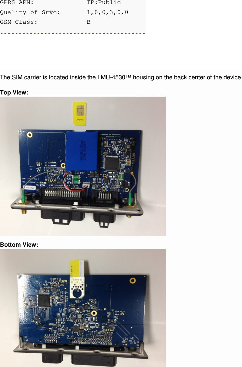
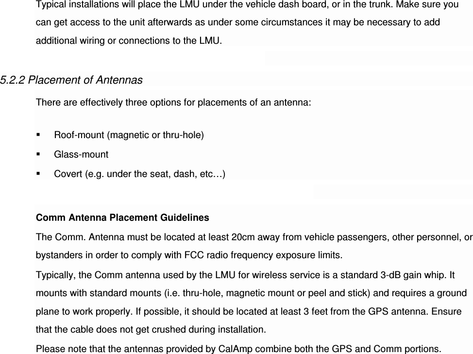
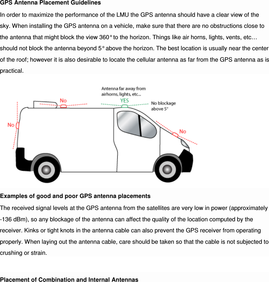
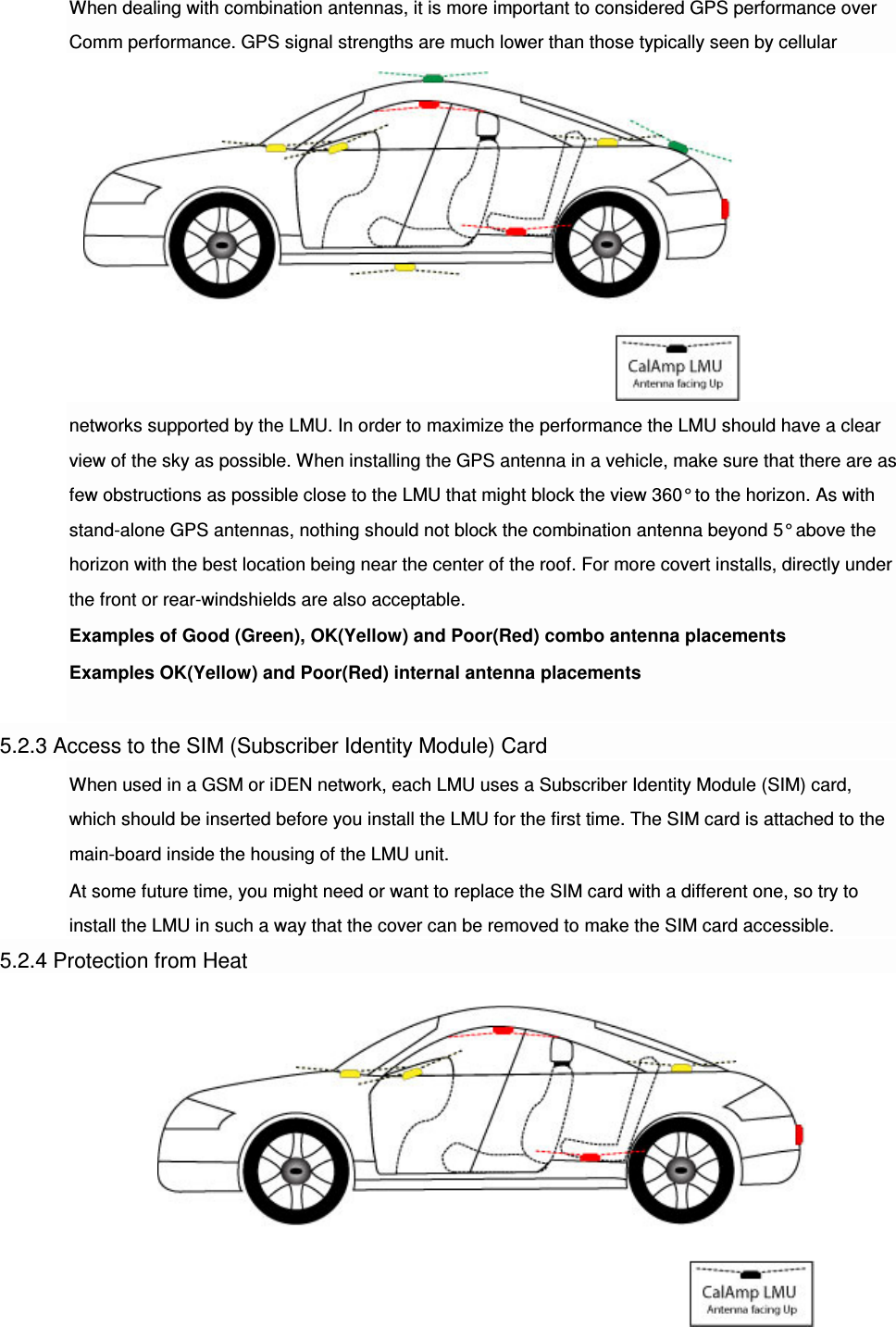
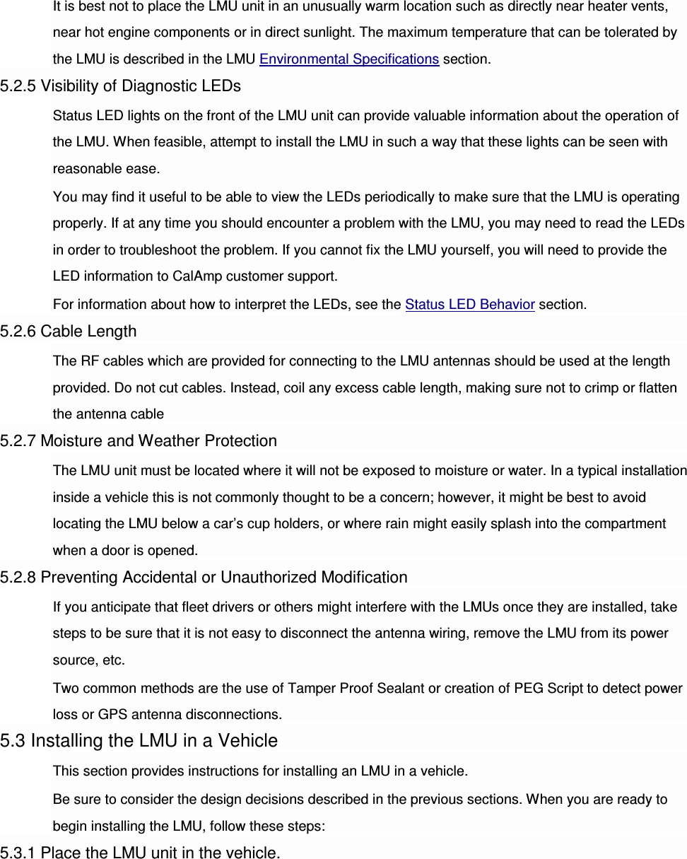
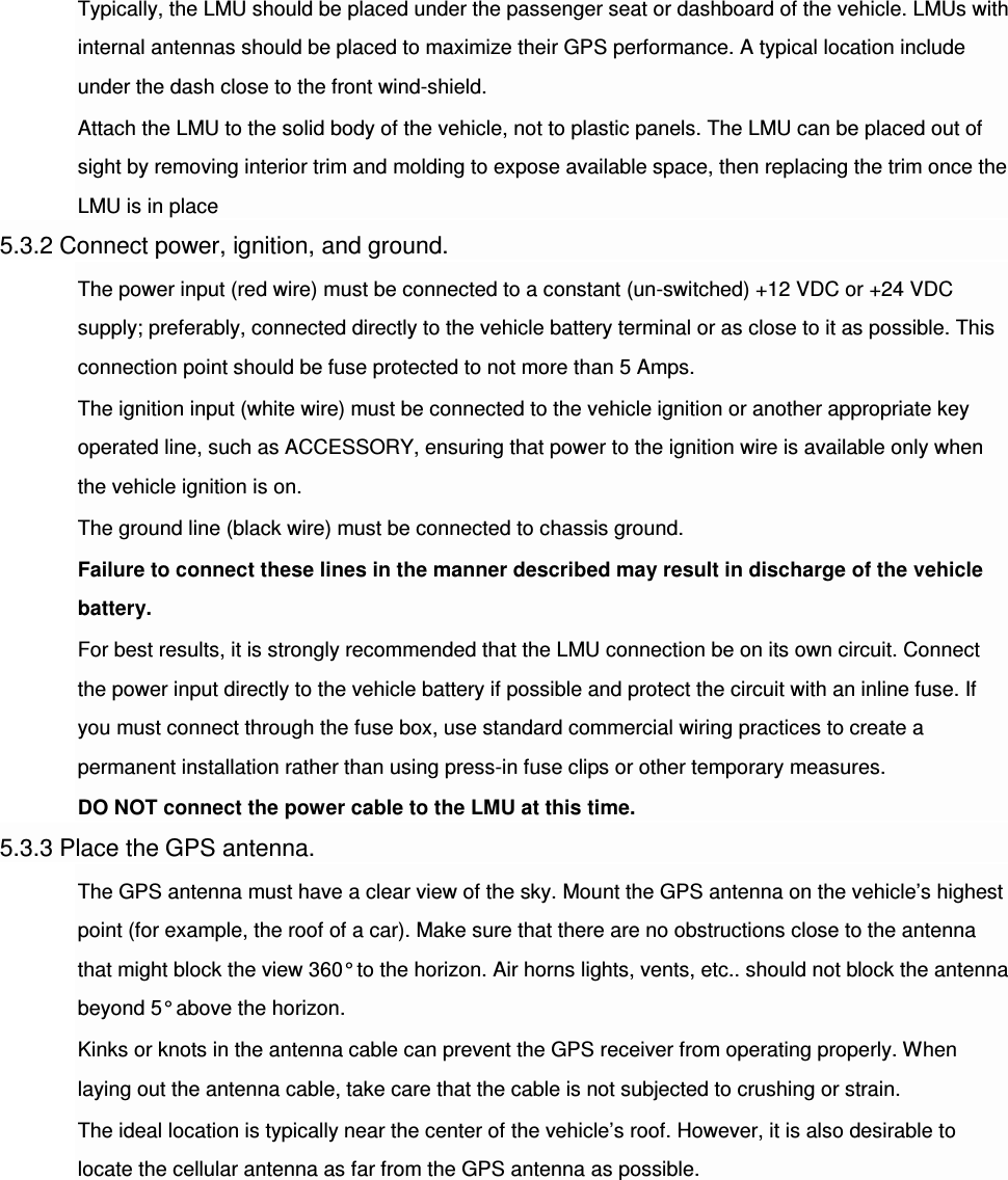
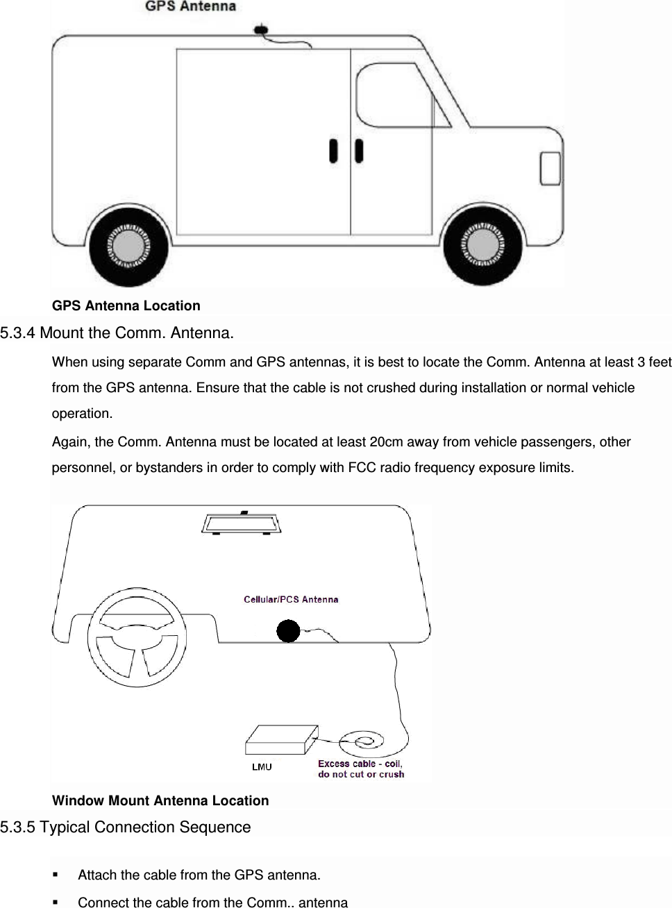
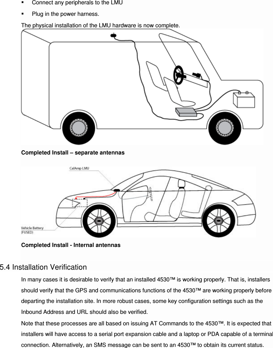
![Once configured, you may verify that the LMU-4530’s™ modem has registered to the CDMA network. Enter: AT$APP COMM STATUS? The response should be similar to: CDMA Service: IS-2000 Connection: Yes RSSI: -80 dBm Channel: 0 Band:Side: 800:B Base Station ID: 0 Network ID: 0 System ID: 4145 ESN (Modem S/N: 2676319948 [9F8566CC] Phone Number: 1234567890 IMSI: 310001234567890 CarrierConfig: 1 The Phone Number field should match the <Phone Number> value you used in step 3 or 4. The last 10 digits of the IMSI field should match the <MSID> value you used in step 3 or 4. 5 Installing the LMU The installation of the LMU and its antennas can have a major impact on the LMU’s performance. It is recommended that installers be familiar with the installation of GPS and cellular devices and are comfortable in a vehicle environment. 5.1 Preparing for Installation Be sure you have received all the LMU components you need. This must include: The LMU to be installed A power harness GPS Antenna (for external devices) Comm Antenna (for external devices) Optional Components:](https://usermanual.wiki/CalAmp/4530HE/User-Guide-2969319-Page-21.png)
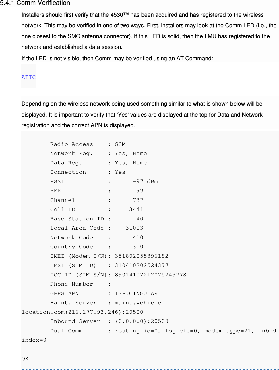
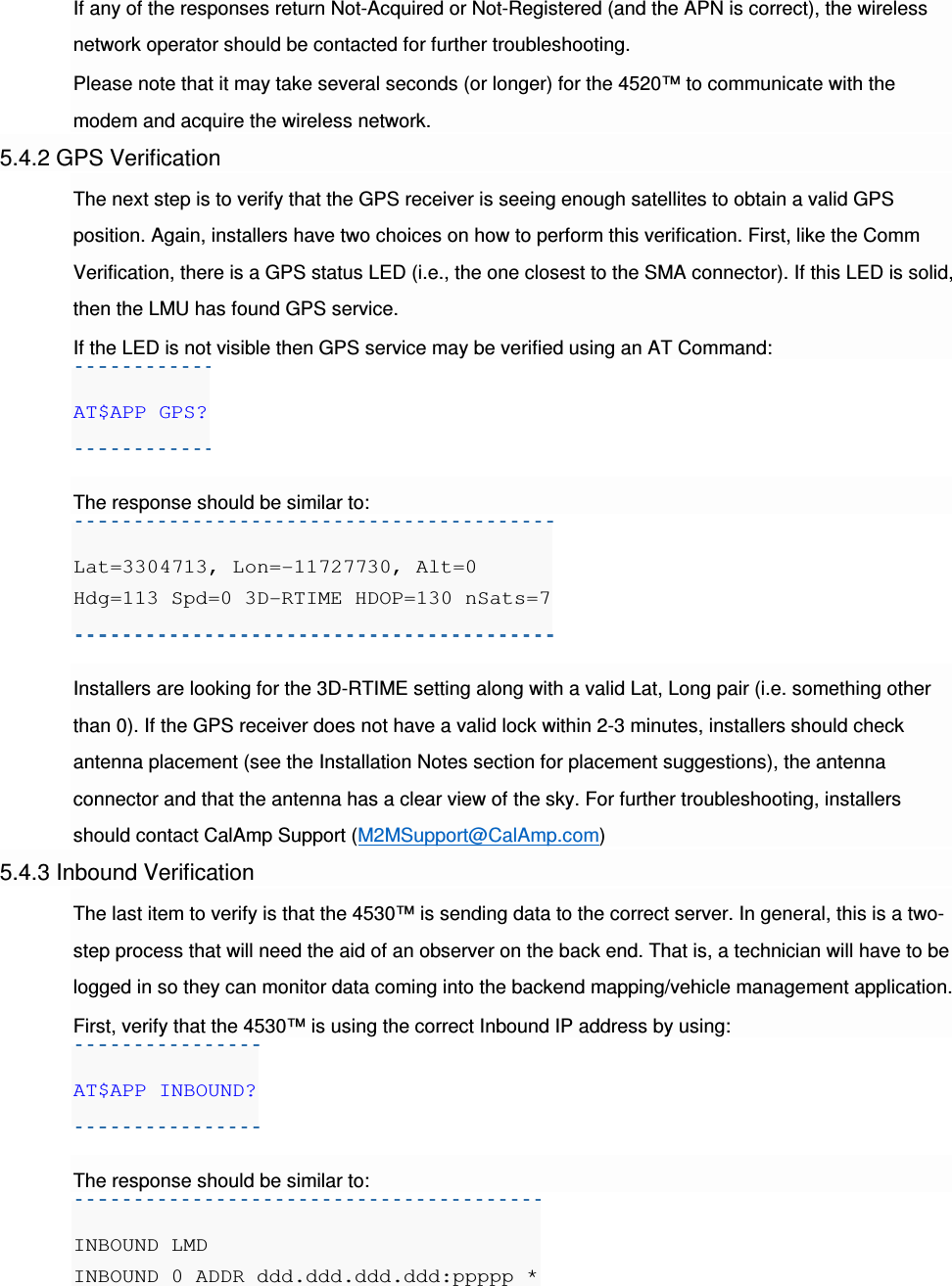
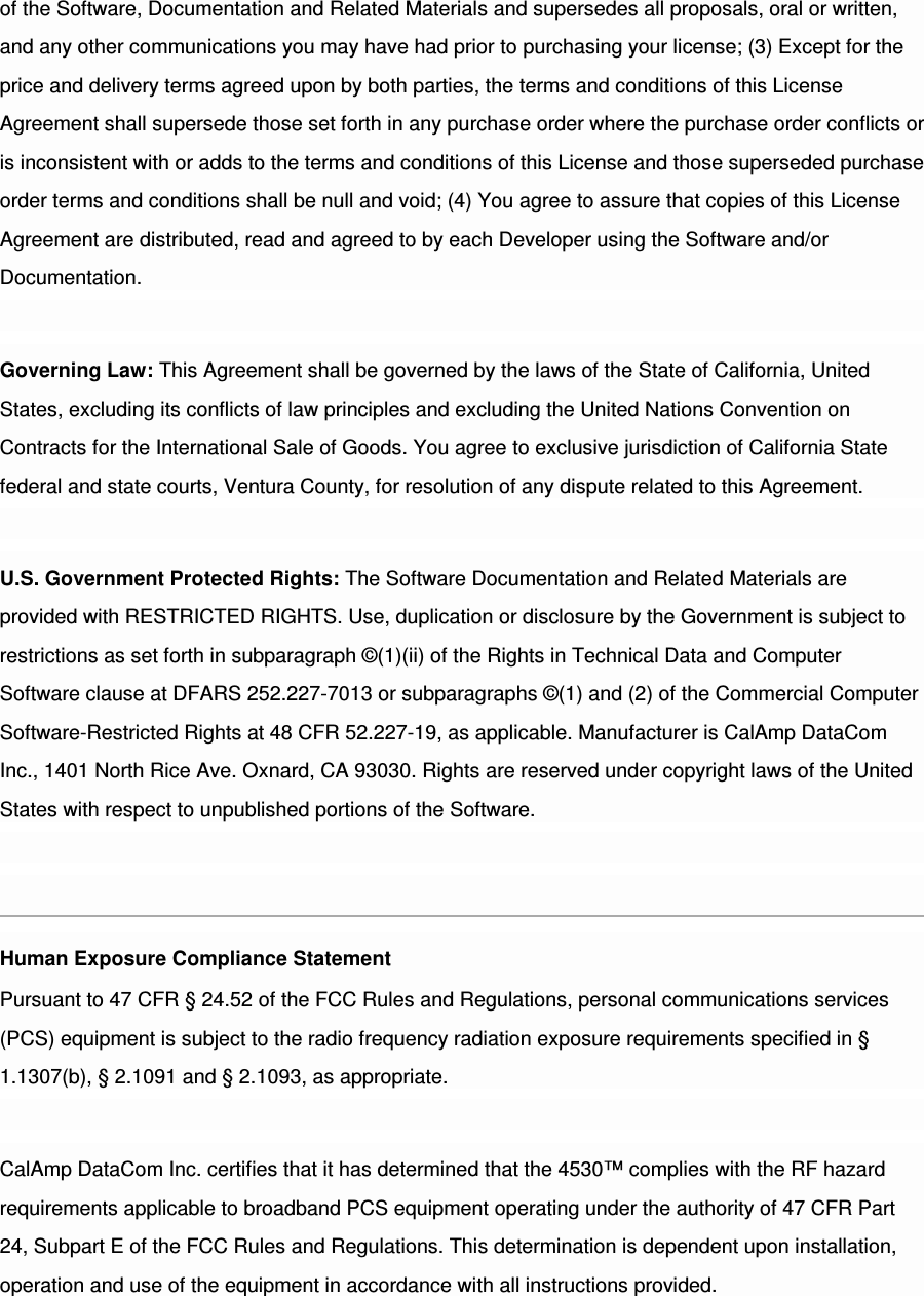
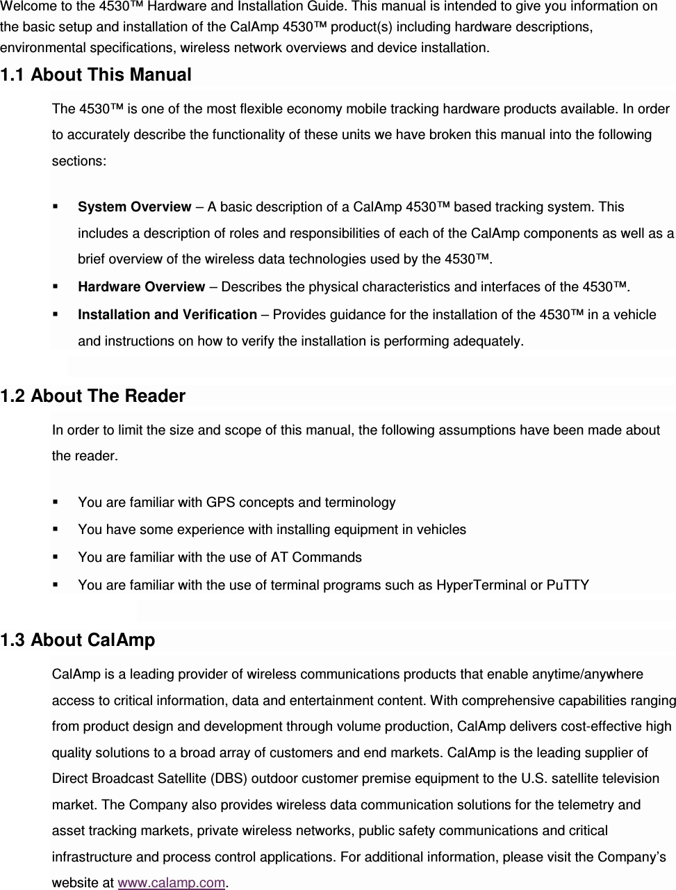
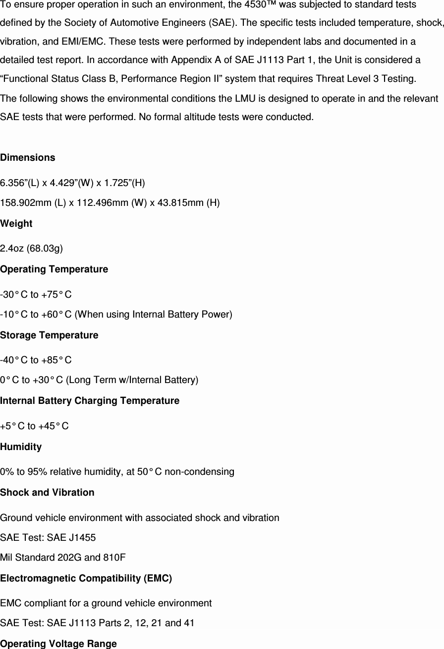
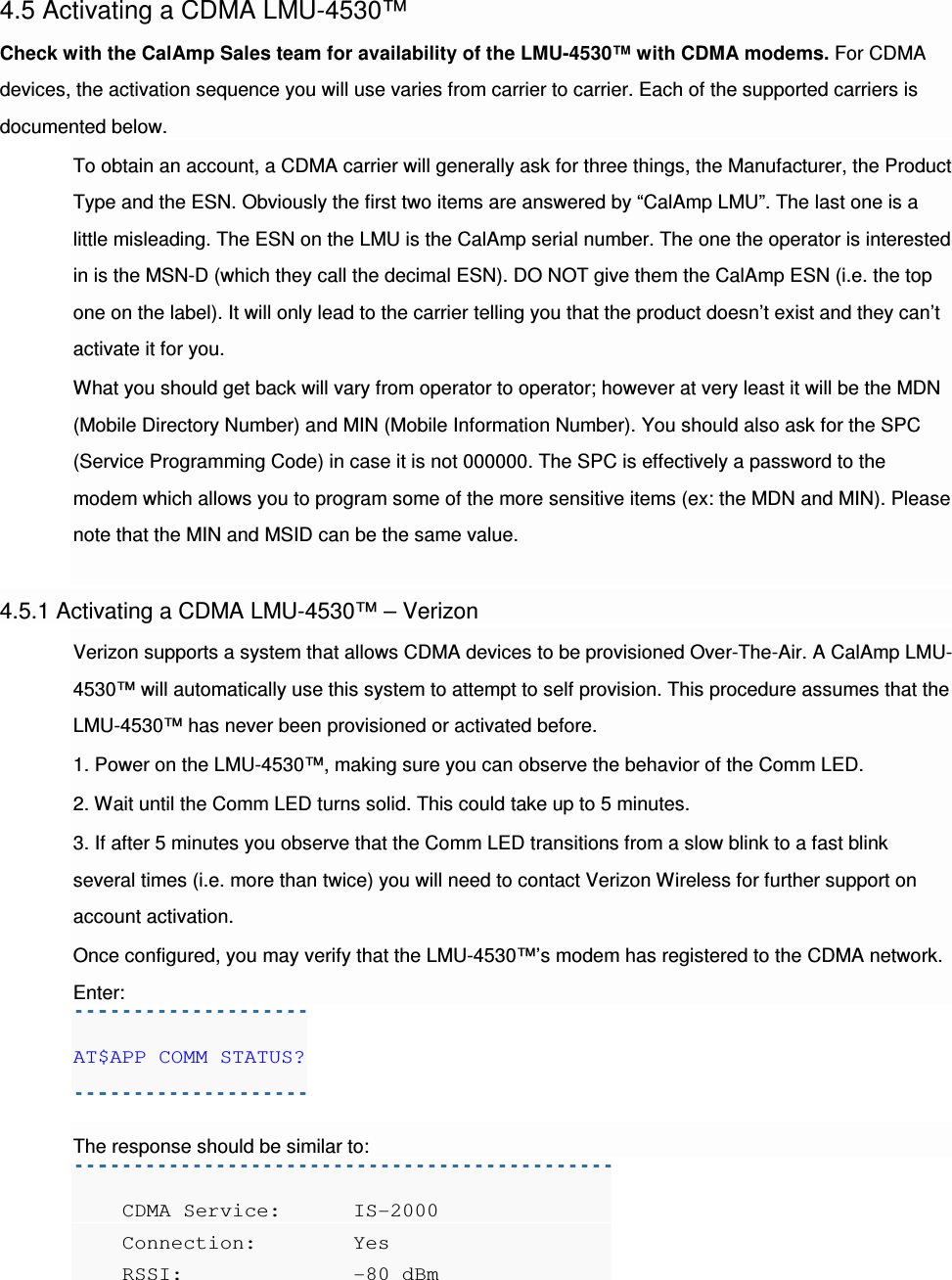
![INBOUND 0 URL myURL.myCompany.com INBOUND 1 ADDR 0.0.0.0:20500 INBOUND 1 URL INBOUND 2 ADDR 0.0.0.0:20500 INBOUND 3 ADDR 0.0.0.0:20500 The installer will need to verify with a backend technician that the, URL (myURL.myCompany.com ), IP address (ddd.ddd.ddd.ddd) and port (<ppppp>) are correct. The second step is to verify that the 4530™ is sending data. The best way to do this is to force the 4530™ to send in an unacknowledged Event Report (i.e., its current GPS location) with the following command: AT$APP PEG SUNRPT 255 The 4530™ will respond with: OK The backend monitor must then be contacted to confirm that they received an Event Report with Event Code 255. Assuming that all three sections have passed, the installation can be considered to be complete. The current Comm, GPS and Inbound status of a GSM LMU can be obtained via SMS provided you have access to an SMS capable phone or PDA. Using your handset, send the following SMS Message to the LMU: !R0 Within a few minutes, the LMU should return a response in the following format: APP: <App ID><Firmware Version> COM:<RSSI> [./d/D][./a/A][./L][IP address] [<APN>] GPS:[Antenna <Short/Open/Off>] | [No Time Sync] | [<FixStatus><Sat Count>] INP:<inputs states><vehicle voltage> MID:<mobile ID><mobile ID type> INB:<inbound IP address>:<inbound port><Inbound Protocol (LMD/LMX)>](https://usermanual.wiki/CalAmp/4530HE/User-Guide-2969319-Page-32.png)
![APP: o <App ID>: The Application ID value of the LMU indicating the host platform and the wireless networking technology of the LMU. o <Firmware Version>: The current firmware version in use by the LMU COM: o <RSSI>: This is the signal strength the wireless modem sees from the network. In general the LMU is at least scanning for the network if the RSSI is not -113. o [./d/D]: If the character ‘D’ is present, it indicates the LMU had a data session established when it responded to the status request. For the 8-Bit product line an upper case ‘D’ indicates both the Inbound and Maintenance sockets are ready. The lower case ‘d’ indicates that only the Maintenance socket is ready. A ‘.’ indicates no sockets are ready. o [./a/A]: This field indicates if the LMU has received an Acknowledgement from the Inbound server. This field will be empty if the LMU has never received an ACK. The lower case ‘a’ will be present if it has received an ACK since the last cold boot (i.e. power cycle) but not the last warm boot (App Restart or Sleep). The upper case ‘A’ will be present if the LMU has received an ACK since the last warm boot. A ‘.’ Indicates no acknowledgement has been received. o [./L]: This field indicates if the LMU’s log is currently active. An ‘L’ indicates that the log is currently in use (i.e. one or more records have been stored) where a ‘.’ indicates the log is inactive. o [IP Address]: This is an optional field if and is only present if the LMU has established a valid data session. This field will contain the current IP address of the LMU as assigned by the wireless network. Note that if you see a value of 192.168.0.0, this is an indication that the LMU has not been able to establish a data session. o [<APN>]](https://usermanual.wiki/CalAmp/4530HE/User-Guide-2969319-Page-33.png)
![The current Access Point Name in use by a GSM LMU. GPS: o [Antenna <Short/Open/Off>]: This field, if present, indicates a problem with the LMU’s GPS antenna. A value of Short indicates that the antenna cable has likely been crushed. A value of Open indicates that the antenna cable is either cut or disconnected. A value of Off indicates that the LMU’ GPS receiver is off. o [No Time Sync]: If this field is present, it indicates that the LMU’s GPS receiver has not been able to find even a single GPS satellite. This would likely been seen in conjunction with the above antenna error, or if the LMU GPS antenna is otherwise blocked. o [<FixStatus><Sat Count>]: If these fields are present it indicates that the LMU has, or had a valid GPS solution. The <Sat Count> field indicates how many GPS satellites are currently in use by the LMU. The <FixStatus> field indicates the type of fix. The Fix Status types are detailed in the LM Direct Reference Guide. INP: o <input states>: This field details the current state of each of the LMU’s discreet inputs. This field is always 8 characters long. The left most character represents the state of input 7 where the right most represents the state of input 0 (i.e. the ignition). A value of 1 indicates the input is currently in the high state. A value of 0 indicates it is currently in the low state. o <vehicle voltage>: This field will contain the current reading of the LMU’s internal A/D. This will be the supply voltage provided to the LMU in mV. MID: o <mobile ID>: This will be the current mobile ID in use by the LMU. o <mobile ID type>: This will be the type of Mobile ID in use by the LMU. The available types are, Off, ESN, IMEI, IMSI, USER, MIN and IP ADDRESS. INB:](https://usermanual.wiki/CalAmp/4530HE/User-Guide-2969319-Page-34.png)