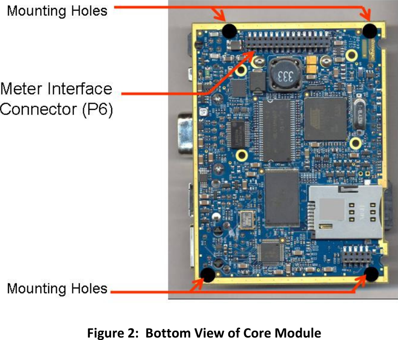
CalAmp 500004 Wireless Communications Module - WiMetry User Manual Integration Manual

CalAmp Corp. Wireless Communications Module - WiMetry Integration Manual

Integration Manual

               WiMetryTM Core Module   Installation Guide R1.1
  Copyright Notice  ©2009 CalAmp Corp. All Rights Reserved.   This guide covers the installation of the CalAmp WiMetry Core Module. Specifications described are typical only and are subject to normal manufacturing and service tolerances.   CalAmp reserves the right to modify the equipment, its specification or this manual without prior notice, in the interest of improving performance, reliability or servicing. At the time of publication all data is correct for the operation of the equipment at the voltage and/or temperature referred to. Performance data indicates typical values related to the particular product. No part of this documentation or information supplied may be divulged to any third party without the express written consent of CalAmp Corp.  Products offered may contain software which is proprietary to CalAmp Corp. The offer or supply of these products and services does not include or infer any transfer of ownership.
  FCC Statements  This  device  complies  with  Part  15  of  the  FCC  Rules.    Operation  is  subject  to  the  following  two conditions:  (1) This device may not cause harmful interference, and (2) This device must accept any interference received, including interference that may cause undesired operation.  This  equipment  has  been  tested  and  found  to  comply  with  the  limits  for  Class  B  Digital  Device, pursuant  to  Part  15  of  the  FCC  Rules.    These  limits  are  designed  to  provide  reasonable  protection against  harmful  interference  in  a  residential  installation.   This  equipment  generates  and  can  radiate radio frequency energy and, if not installed and used in accordance with  the instructions, may cause harmful interference to radio communications.  However, there is no guarantee that interference will not  occur  in  a  particular  installation.    If  this  equipment  does  cause  harmful  interference  to  nearby electrical  devices,  the  user  is  encouraged  to  try  to  correct  the  interference  by  one  or  more  of  the following measures.  • Reorient or relocate the receiving antenna • Increase the separation between the equipment and receiver • Connect  the  equipment  into  an  outlet  on  a  circuit  different  from  that  to  which  the  receiver  is connected • Consult CalAmp technical support for help  Any changes or modifications not expressly approved by the party responsible for compliance could void the user’s authority to operate the equipment.  To comply with FCC regulations for the device, the following rules must be obeyed during and after installation  Keep the cellular antenna of the Cell Module at a safe distance from your head and body while the modem is in use.   Maintain a distance of at least 20 cm (8 inches) between the transmitter’s antenna and any person while in use.  This device is designed for use in applications that observe the 20 cm separation distance.   Consult the Cell Module installation guide for information on approved antennas.    Non-Collocation for External Antenna  External antenna must not be collocated or operating in conjunction with any other antenna or transmitter.  Collocation is defined as any antenna or radiating element positioned within 20cm of another antenna or radiating element.  The supplied internal antenna for 802.15 will insure 20cm separation from a properly mounted, vertically positioned external cellular antenna.  Only FCC approved antennae can be used with the 802.15 transceiver.  Consult with CalAmp, Corp. or FCC OET website, www.fcc.gov/oet/, for a list of approved antenna solutions for this device.
  Safety Issues  The use of cellular telephones or devices in aircraft is illegal. Use in aircraft may endanger operation and disrupt the cellular network. Failure to observe this restriction may result in suspension or denial of cellular services to the offender, legal action or both.    Do not operate in the vicinity of gasoline or diesel-fuel pumps unless use has been approved and authorized  Do not operate in locations where medical equipment that the device could interfere with may be in use  Do not operate in fuel depots, chemical plants, or blasting areas unless use has been approved and authorized  Use care if operating in the vicinity of protected personal medical devices, i.e., hearing aids and pacemakers  Operation in the presence of other electronic equipment may cause interference if equipment is incorrectly protected. Follow recommendations for installation from equipment manufacturers.
   Contents  1.  OVERVIEW ........................................................................................................................................ 6 1.1. Advisory Symbols ......................................................................................................................... 6 1.2. Module Identification ................................................................................................................... 6 1.3. General Description...................................................................................................................... 7 1.4. External Connectors ..................................................................................................................... 8 2.  EXTERNAL INTERFACES ................................................................................................................... 10 2.1. Power Connection ...................................................................................................................... 10 2.2. EIA-232 DB-9 connector ............................................................................................................. 11 2.3. External I/O ................................................................................................................................ 12 2.4. Meter Interface Connector (P6) ................................................................................................. 14 2.5. Status LEDs ................................................................................................................................. 15 2.6. COTS Interfaces .......................................................................................................................... 15 Ethernet ............................................................................................................................................ 16 USB Device ........................................................................................................................................ 16 USB Host............................................................................................................................................ 16 2.7. Cellular Module .......................................................................................................................... 16 2.8. 802.15 Antenna .......................................................................................................................... 16 3.  GENERAL INSTALLATION GUIDELINES ............................................................................................ 17
  1. OVERVIEW  1.1. Advisory Symbols       Warning!  Improper usage or handling may cause non-compliant device operation.         Warning!  High voltage presents risk of injury due to electric shock.       Direct Current (DC).     1.2. Module Identification  The label contains the CalAmp part number, serial number, IC and FCC ID numbers.  Additional labeling will be required on the end device.
  1.3. General Description  The CalAmp WiMetryTM Core Module is an Internet Protocol-based, bidirectional wireless data concentrator platform used for advanced metering and demand response monitoring and control applications. The platform also has other smart grid applications and facilitates real-time acquisition of critical usage and rate data from electric, gas or water meters via public wireless networks and the Internet.   The WiMetryTM platform supports the latest in cellular 3G high-speed data communications and is backward compatible to existing EV-DO Rev. 0 and 1x networks.  WiMetryTM takes advantage of ongoing investments made by cellular network operators to build-out, improve and maintain ubiquitous, reliable wireless networks using the latest standards, thereby enabling utility companies to focus on their core business rather than having to establish their own proprietary wireless networks.   The Core Module is designed to be easily integrated into various end devices.  This document describes the process and rules for integrating the core module into an end device.     It includes descriptions of all external interfaces and instruction on how to communicate and power the device.  This document does not cover the software functionality of the device.  Refer to end product documentation for more information on the application software.
  1.4. External Connectors  See the images below for location of external connectors.     Figure 1:  Top View of Core Module
    Figure 2:  Bottom View of Core Module
  2. EXTERNAL INTERFACES  2.1. Power Connection The connector on the core module is the Molex 43045-0401:    The mating connector (required for the power cable) is the Molex 43025-0400.    The contact required on the mating cable is the Molex 43030-0002  The core module is powered either from the J18 power connector or from the Meter Interface Connector.  The pinout of the J18 power connector is below.  The pinout of the Meter Interface Connector is in its own section.    For specifications on the digital input, see the External I/O section.    Table 1:  DC Power Connector (J18)  Pin Signal 1 V_IN (9-28VDC) 2 GND 3 DIGITAL_IN4 4  NO CONNECT  Note:  Do not connect independent power supplies to the power connector and the power inputs on the Interface Board Connector (P6).  The power inputs are shorted on the core module and connecting both could cause a high current condition.     Pinout
  2.2. EIA-232 DB-9 connector  The concentrator contains a standard DB-9 female serial port connector that contains all the required signals for EIA-232 serial communication per the EIA-232 specification.    The table below provides the information to purchase or cables to connect to the DB-9 female connector on the core module.    Note:  All signal names and directions are from the perspective of the core module   Table2 : DB9 EIA-232 Pin-out (P4)  Function Pinout DB9 female (Port 1 only) Direction DCE Ready DSR 6  Output Line Signal Detect 1  Input Clear to Send (CTS) 7  Input Receive* 3  Input Request to Send (RTS) 8  Output Transmit* 2  Output Ground* 5  NA DTE Ready (DTR) 4  Input  * Required Signal   Pinout
  2.3. External I/O  The Core Module contains a variety of digital and analog external I/O.  This I/O can be used to interface with external sensor or logic.   The connector on the core module is the Molex 43045-0101:    The mating connector (required for the power cable) is the Molex 43025-1000.    The contact required on the mating cable is the Molex 43030-0002  Table 3:  I/O Connections (J8)  Pin Signal 1 DIGITAL OUT 2 2 DIGITAL GND 3 DIGITAL IN 3 4 ANALOG GND 5 ANALOG IN 3 6 DIGITAL OUT 1 7 DIGITAL IN 2 8 DIGITAL IN 1 9 ANALOG IN 1 10 ANALOG IN 2  Pinout    External I/O Specifications:    Analog Inputs:   Input Voltage Range: 0-28VDC, 10-bit resolution
  Digital Inputs: Input Voltage Range: 0-28VDC, 1.5V logic threshold  Digital Outputs:   Open Collector Outputs, 0-28VDC, 1Amp max current
  2.4. Meter Interface Connector (P6)    The Meter Interface connector is Samtec MMS-115-02-L-DV  The Mating Connector to the Meter interface Connector is the Samtec TW-15-07-L-D-570-090.  This connector is a surface mount connector and must be mounted to a mating PCB.    Table 4:  MIB Pinout  Pin Signal Direction Function 1 V_IN (9-28VDC)  NA   2 GND  NA   3 V_IN (9-28VDC)  NA   4  GND  NA   5  /MIB_AC_MON  Input  Indicates the presence of AC voltage input (active low) 6  /DB9_DISABLE  Input  Drive low to indicate the presence of a interface board 7  /MIB_BATT_MON  Input  Indicates the presence of Battery voltage input (active low) 8  /MIB_DIAB_PB  Input  Force the core module to run a diagnostic check (active low) 9  /MIB_OTA_PB  Input  Force the core module’s cell module to perform an over the air activation  10  IO_DIN3  Input  General Purpose Digital Input 11  DOUT3  Output  General Purpose Digital Output (0-3.3VDC) 12  DOUT4  Output  General Purpose Digital Output (0-3.3VDC) 13  MIB_METER_TYPE  Output  Indicates the type of meter the board is communicating with (See MIB Meter Type) 14  MIB_232_485  Output  Controls the communication type; RS232 (logic high) or RS485 (logic low) 15  MIB_485_DIR  Output  Controls the direction of the RS485 transceiver, transmit (active high), receive (active low) 16  MIB_485_4W/2W  Output  Commands the RS485 to be a 4 wire (active high) or 2 wire (active low) interface 17  MIB_232_PORT_A2  Output  MUX driver that controls which serial port (1-8) is active.   18  MIB_232_PORT_A1  Output  MUX driver that controls which serial port (1-8) is active.   19  MIB_232_PORT_A0  Output  MUX driver that controls which serial port (1-8) is active.   20  MIB_DCE_TXD  Input  RS232 Receive Line 21  MIB_DCE_RXD  Output  RS232 Transmit Line 22  DCE_RTS  Input  RS232 Clear to Send Line
  23  DCE_CTS  Output  RS232 Request to Send Line 24  DCE_DTR  Input  RS232 Data Set Ready 25  DCE_DSR  Output  RS232 Data Terminal Ready 26  DCE_RI  Output  RS232 Ring Indicator 27  DCE_DCD  Output  RS232 Data Carrier Detect 28  NO CONNECT    NA 29  AT91_BMS  Input  Boot Mode Select:  Internal (Active High), External (Active Low) 30  NO CONNECT    NA  Pinout   2.5. Status LEDs  Status LEDs are installed on the Core Module.    LEDs on the Core Module LED1(802.15):    Indicates activity on the 802.15 link LED2(Signal):     Indicates a sufficient RSSI on the cell signal LED3(Activity):    Shows activity on the cellular link LED4(Service):    The unit has connected to a cellular network LED5(Power):     The Core Module is powered   2.6. COTS Interfaces  The following interfaces are industry standard and use off the shelf cables for communication.  No customization is required.
  Ethernet Auto-Negotiating, Auto-MDIX, 10/100Mbps Ethernet LAN interface via an RJ-45 connector, with status indicators. USB Device USB v2.0, Low or Full speed, Device port via a Type-B style connector. USB Host USB v2.0, Low or Full speed, Host port via a Type-A style connector.   2.7. Cellular Module  The Core Module contains a mini PCI express connector (P3) for connecting a 3G cell module.  CalAmp will install the cell module prior to shipment.  The Cell module will contain its own unique antenna connector and installation requirements.   Refer to cell module manufacturer product documentation for installation rules and antenna options with regards to FCC certification.      2.8. 802.15 Antenna  To insure FCC compliance, the Core Module 802.15 modular transmitter utilizes a U.FL antenna coupler and requires a unique coaxial feed assembly direct to the external antenna.  Any antenna used with the module must meet certification requirements.       To  comply  with  FCC  approval  for  the  EVDO device,  do not  use  a 2.4GHZ  antenna with  a gain greater than 2dBi.      To comply with FCC approval for the device, do not place the 802.15 antenna within 20cm of the cellular antenna or any other antennas in the system.
  3. GENERAL INSTALLATION GUIDELINES  Refer to module overview images, Figures 1 and 2, for locations of mounting holes.    The core module is mounted using the four mounting holes on the corners of the module using #4 screws.  Although not necessary for emissions compliance, it is recommended that each mounting hole or the associated edge copper rails are electrically connected to the chassis ground of the assembly enclosure.  Minimum single-shielded coax is required for emissions compliance of both cellular and 802.15 antenna feeds.  Cables should route across top side of board, preferably outside of PWA perimeter.  Enclosures and cable feed recommendations are shown below.
  This page intentionally left blank.

Navigation menu