user manual

CalAmp WPAN Module
Installation Guide
R1.0
Copyright Notice
©2009 CalAmp Corp. All Rights Reserved.
This guide covers the installation of the CalAmp Zigbee Module. Specifications described are typical
only and are subject to normal manufacturing and service tolerances.
CalAmp reserves the right to modify the equipment, its specification or this manual without prior
notice, in the interest of improving performance, reliability or servicing. At the time of publication all
data is correct for the operation of the equipment at the voltage and/or temperature referred to.
Performance data indicates typical values related to the particular product. No part of this
documentation or information supplied may be divulged to any third party without the express written
consent of CalAmp Corp.
Products offered may contain software which is proprietary to CalAmp Corp. The offer or supply of
these products and services does not include or infer any transfer of ownership.
FCC Statements
This device complies with Part 15 of the FCC Rules. Operation is subject to the following two
conditions: (1) This device may not cause harmful interference, and (2) This device must accept any
interference received, including interference that may cause undesired operation.
This equipment has been tested and found to comply with the limits for Class B Digital Device,
pursuant to Part 15 of the FCC Rules. These limits are designed to provide reasonable protection
against harmful interference in a residential installation. This equipment generates and can radiate
radio frequency energy and, if not installed and used in accordance with the instructions, may cause
harmful interference to radio communications. However, there is no guarantee that interference will
not occur in a particular installation. If this equipment does cause harmful interference to nearby
electrical devices, the user is encouraged to try to correct the interference by one or more of the
following measures.
• Reorient or relocate the receiving antenna
• Increase the separation between the equipment and receiver
• Connect the equipment into an outlet on a circuit different from that to which the receiver is
connected
• Consult CalAmp technical support for help
Any changes or modifications not expressly approved by the party responsible for compliance could
void the user’s authority to operate the equipment.
To comply with FCC regulations for the device, the following rules must be obeyed during and after
installation
Keep the antenna of the Module at a safe distance from your head and body while the modem is in
use. Maintain a distance of at least 20 cm (8 inches) between the transmitter’s antenna and any
person while in use. This device is designed for use in applications that observe the 20 cm separation
distance.
Non-Collocation for External Antenna
External antenna must not be collocated or operating in conjunction with any other antenna or
transmitter. Collocation is defined as any antenna or radiating element positioned within 20cm
of another antenna or radiating element.
Only Calamp approved antennae can be used with the CalAmp WPAN Module. Contact Calamp for a
list of approved antennas.
The antennas used for the initial filing are;
Pulse W1030 (External)
Antenova A6250 (Internal)
The max gain on an antenna is 2dBi. Do not use an antenna with a higher gain.
Contents
1. OVERVIEW ........................................................................................................................................5
1.1. Advisory Symbols ........................................................................................................................ 5
1.2. Module Identification ................................................................................................................. 5
1.3. General Description .................................................................................................................... 6
1.4 Module Images ........................................................................................................................... 6
2. EXTERNAL INTERFACES.....................................................................................................................8
2.1. Mechanical Connection .............................................................................................................. 8
2.3 Power .......................................................................................................................................... 9
2.4 External I/O ................................................................................................................................. 9
2.5 System Reset............................................................................................................................. 10
2.6 Power Supply Enable ................................................................................................................ 10
2.7 UART.......................................................................................................................................... 10
2.8 SPI.............................................................................................................................................. 10
2.9 WPAN Antenna ......................................................................................................................... 10

1. OVERVIEW
1.1. Advisory Symbols
Warning! Improper usage or handling may cause non-compliant device operation.
Direct Current (DC).
1.2. Module Identification
The label contains the CalAmp part number, serial number, IC and FCC ID numbers. Additional labeling
will be required on the end device.
Any end device that integrates the WPAN module must include the following statement on its label:
Contains FCC ID: J26-500005
1.3. General Description
The CalAmp WPAN Module is a short range communication module based on the IEEE 802.15.4
specification.
The CalAmp Module is designed to be easily integrated into various end devices. This document
describes the process and rules for integrating the WPAN module into an end device. It includes
descriptions of all external interfaces and instruction on how to communicate with and power the
device. This document does not cover the software functionality of the device. Refer to end product
documentation for more information on the application software.
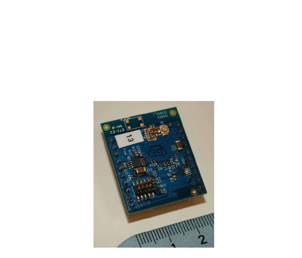
1.4 Module Images
Figure 1: Top View of WPAN Module

Figure 2: Bottom View of WPAN Module

2. EXTERNAL INTERFACES
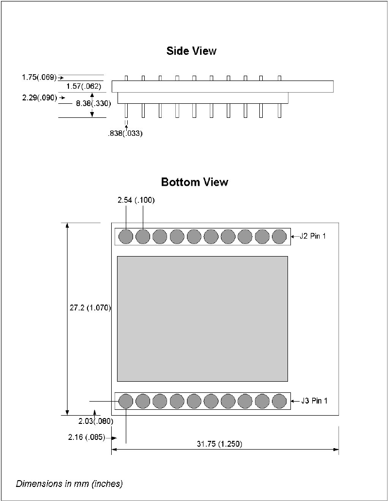
2.1. Mechanical Connection
There are two 10 pin, through hole, board to board connectors on the module that are used both for
communication, power, and mechanical mounting of the module. The two board to board connectors
are the Molex 22-28-4100.
The pins on the I/O connectors can be soldered directly to the mating PCB. The module can also plug
into a mating connector for the 22-28-4100. There are several options available from Molex for a
mating plug. Contact Molex for more information on the mating connector options. The module has
been tested to work properly with the Molex 44812-0028 PCB mount connector.
Table 1: Interface Connector (J2)
Pin
Signal
1 UART_RTS
2 UART_CTS
3 UART_TXD
4 UART_RXD
5 SPI_MOSI
6 SPI_MISO
7 SPI_CLK
8 \SPI_CS
9 GPIO1
10 GPIO2
Table 2: Interface Connector (J3)
Pin
Signal
1 GPIO3
2 GPIO4
3 PWR_ENABLE
4 GPIO5
5 GPIO6
6 \SYS_RESET
7 VIN (3.3-5.5VDC)
8 VIN (3.3-5.5VDC)
9 GND
10 GND

2.3 Power
The module must be powered externally with a DC voltage between 3.3 and 5.5VDC. The current draw
of the module is listed below.
Transmit Peak = 250mA
Receive = 50mA
Standby = 25mA
Sleep = <1mA
2.4 External I/O
The Calamp WPAN Module contains a variety of digital and analog external I/O. This I/O can be used
to interface with external sensor or logic. Unless otherwise noted the following ratings cover the
following pins (GPIO1-6, SYSRESET, PWR_ENABLE, UART, and SPI).
Parameter Rating
Vin (Logic 1) Min 2.4V
Vin (Logic 1) Max 3.3V
Vin (Logic 0) Min -.3V
Vin (Logic 0) Max 1.26V
Output Current (all except GPIO2 and GPIO4) 4mA
Output Current (GPIO2, GPIO4) 8mA
All GPIOs can be used as standard digital I/O with the specifications above. Some GPIOs can be
configured as other I/O options described below.
Analog: Pins with the analog functionality are connected to the internal ADC of the module. The pins
can read any voltage between 0 and 3V.
Interrupt: These pins can be configured as an interrupt for the main application processor on the
module.
Timer: These pins can be configured as timer I/O based on the internal clock of the module.
GPIO Function
GPIO1 Digital Only
GPIO2 Digital, Timer, High Current
GPIO3 Digital, Analog, Timer
GPIO4 Digital, Analog, Interrupt
GPIO5 Digital, Analog
GPIO6 Digital, Analog

2.5 System Reset
The module can be reset by holding pin J3-6 low for at least 26uS. This pin contains an internal
10K pullup.
2.6 Power Supply Enable
The power supply on the module can be shut down by holding the PWR_ENABLE line low.
The supply will remain disabled as long as the line is held low and will restart when the line goes
high. This will have the same effect as resetting the device. This pin contains an internal 10K
pullup
2.7 UART
Note: The signal naming convention on the module is the standard naming for a RS232 Client device,
therefore the UART_TX line is an input to the module, and the UART_RX line is an output.
The UART_TX and UART_RX lines are configured as standard UART serial communication lines. The
UART_RTS and UART_CTS lines are optional flow control signals.
2.8 SPI
The SPI lines are configured per the SPI standard. The module will act as a master on the SPI bus.
2.9 WPAN Antenna
This section is not applicable to module versions with a surface mount antenna.
To insure FCC compliance, the WPAN Module modular transmitter utilizes a U.FL antenna coupler and
requires a unique coaxial feed assembly direct to the external antenna. Any antenna used with the
module must meet certification requirements.
To comply with FCC approval for the device, do not place the WPAN antenna within 20cm
of any other transmitting antennas.
To comply with FCC approval for the device, do not use an external antenna with a gain of
more than 2dBi. Contact CalAmp for a list of approved antennas.
3.0 GENERAL INSTALLATION GUIDELINES
Refer to module overview images, Figures 1 and 2, for locations of mounting holes.
The WPAN module is mounted be either soldering the through hole pins of J3 and J2 to a mating PCB
or to a mating connector on a PCB. Refer to the mechanical outline below for connector placement
and spacing. Refer to Molex documentation for additional information on PCB footprints for the 22-
28-4100 connector.
Antenna Considerations:
When using a surface mount antenna, the module must be mounted in a way that the antenna may
radiate away from other ground planes or metal in the system. For best results, keep ground planes
and other metal objects as far from the antenna as possible.
When using a external cabled antenna, use only antennas approved by Calamp for use with this
module.