CalAmp 520005-1 MDS-MMDS Transceiver, Model 520005-1 User Manual Instruction guide
CalAmp Corp. MDS-MMDS Transceiver, Model 520005-1 Instruction guide
CalAmp >
Contents
Instruction guide

C+A
1
C+A
TRANSCEIVER INSTALLATION GUIDE
____________________________________________________
The installation of California Amplifier products should only be attempted by
qualified personnel, and should be under the direct guidelines of the system
operator. These installation instructions apply to California Amplifier products
only. Use of these instructions to install other manufacturer’s products may
result in unknown hazards, damage and/or unacceptable performance.
The information contained in this applications note is intended to assist the
operator in developing a set of installation guidelines and operating practices for
the field personnel skilled in installing roof top subscriber equipment.
California Amplifier accepts no responsibility for claims of injury, death,
destruction of property or loss of television service related to improper
installation, or installation of equipment by staff not skilled in installing roof top
cable television equipment.
460 Calle San Pablo, Camarillo, California 93012 USA PH: (805) 987-9000 Fax (805) 987-8359
C+A
2
GENERAL INSTALLATION
INSTRUCTIONS FOR MDS-MMDS
TRANSCEIVER
NOTE to System Operator:
The AirStream Transceiver has been designed for installation by a licensed
or qualified installer with experience in installing wireless antennas.
NOTE to Installer: The authority to operate this device requires its operation and
installation, including antennas, to comply with the FCC-adopted radio frequency
(RF) exposure limits. It is in the responsibility of the installer to install this device
and associated antennas so that RF exposures to people do not exceed
1.0mW/cm2. The power output near of this transceiver at the antenna exceeds the
FCC adopted RF exposure limits for people. When used with an antenna with a
maximum gain of 17 dBi the exposure limit is satisfied if the antenna is at least
30 centimeters or 12 inches away from all people.
INSTALLATION PRACTICES
In a customer installation, there are several factors that must be considered before the
installation can take place: Signal contour strength and direction of the transmitting
source, seasonal interference’s such as foliage and trees, aesthetics of the outdoor
installation, system performance and overall customer satisfaction with the final product.
In each case the customer wants the very best signal quality with a minimum of
construction and aesthetic impact to their home or business. This will dictate the use of
a variety of antenna configurations in order to perform the task of providing adequate
signal strength while maintaining low visual impact. The order of visual impact follows
the height and size of the antenna. A wall or gutter mount will present a very low visual
profile. This if followed by a short roof or chimney mount. When higher gain or foliage
clearance is needed, then a tree mount or mast mount should be considered.
The following mounts are described and their general application:
Wall or Standoff Mount: These are used in high signal density areas where antenna
aesthetics is of concern. It offers great flexibility in mounting angles and locations. The
stand-off arms mount from the wall and or the eave and support the mast in the vertical
position. The mast may be short in length so as to place the antenna above the roof

C+A
3
line or a telescoping mast may be used in conjunction with a ground plate to extend the
antenna height to above the roof peak.
Roof Mounts: The same basic hardware used for wall and eave mounts is used for a
roof mount. This mounting bracket and pole is adjustable in the vertical plane and will
raise the antenna about 24” above the mounting location. The bracket must be secured
into a structural member, not simply into siding or shingles. All points of attachment
must be properly waterproofed.
Chimney Mounts: Chimney mounts are one of the easiest types of mounts to install.
In the application of brick-type chimneys, a dual band strap mount is best. The proper
strap will securely fasten the mounting bracket and antenna. For wood over metal
construction chimney, a version of the wall mount is best. Make sure the anchor bolts
attach to a supporting stud member and not just the fascia board.

C+A
4
Tripod Mount: The tripod mount offers ease of installation, stable mounting structure,
and signal visibility. It is however, bulky and not very aesthetic. The tripod mount
comes in 3, 5, 10 and 15-foot sections. As with the roof mount installation, the
mounting bolts must always be attached to roof joists and be properly sealed.
Tree Mounts: In regions of the country with heavy foliage, tree mounts are popular.
This is a highly specialized installation and is beyond the scope of this installation guide.
Specific instructions and practices can only be formatted by the individual operator in
their region (not pictured).
Every installation must adhere to company policies, applicable specifications and
drawings of the system operator. This requirement includes: the choice of antennas,
the weatherproofing of all connections, all penetrations into the building and all
grounding procedures, both at the antenna mount and at the point of drop entry into the
building.

C+A
5
INSTALLATION PLANNING
In addition to meeting the highest standards of quality and workmanship, another valid
goal is to minimize the amount of time spent on a customer’s property, thus minimizing
any disruption of a customer’s schedule. Good planning helps an installer to be efficient
and productive on each installation.
Site Survey
Although the general receive location may have been previously surveyed by a signal
crew, a detailed, on-site survey is usually required prior to beginning an install. During
this survey, signal readings must be recorded on the installation work order. The exact
components that were used as well as the mast height should be noted at this time.
You should also create a simple drawing of the antenna installation, including structural
supports and ground system relative to the layout of the house, generally drawn on the
back of the work order.
Testing for Signal Strength with a Site Survey Rig
The first step of the site survey is to verify where the best signal reception is
accommodated on the customer’s home. Most installers are provided with a test kit that
includes a lightweight, telescoping, fiberglass push-up mast with attached antenna. The
antenna gain should be specified by the system engineering staff.
The most satisfactory method to ensure clear and adequate system performance is to
achieve a signal-to-noise (S/N) ratio of at least 30 dB. This ratio is measured using a
signal level meter/QAM analyzer and may be calculated for California Amplifier
transceivers with reasonable accuracy, using the formula below:
S/N = 25 + Transceiver IF Output Level (in dBmv)
TECHNICAL TIP: When reading signal levels, an installer must always be aware of
physical factors that can affect system performance. Microwave signals are highly
susceptible to absorption by trees and other foliage. A wireless antenna thus cannot
view the transmitter from behind a tree. Distant trees can also cause reception
problems. While they may not be visible to an installer, they may still lie in the
transmission path. Signal fluctuations exceeding 2 dB during a survey may be an
indication of distant foliage problems.
Foliage from winter to summer will affect the strength of the received signal. Trees that
are barren in the winter present very little signal attenuation. In the summer when the
trees are full of foliage the attenuation can be as high as 10 dB per tree in the line sight
path. NEVER attempt to receive a signal through a barren or partially barren tree.
C+A
6
Of course, hills and large buildings can completely obscure or deflect microwave signs.
Still other interesting problems can result when the microwave beam grazes the top of a
hill or building, partially deflecting the beam, or when reflective surfaces (bodies of
water, buildings, etc.) cause multiple signal paths from the transmitter into the receive
antenna, a problem known as “multi-path” can occur.
Never use a signal received from a reflection as its reception characteristics can change
drastically over time. Only line-of-sight signals should be used.
GENERAL INSTALLATION GUIDELINES
CAUTION - EXTREME DANGER - OVERHEAD WIRES
When installing any outside antenna, be very aware of all overhead electrical wire
and service feeds. Contact with power lines could be catastrophic and INJURY or
DEATH may result. When faced with a difficult antenna installation location, do
not proceed - contact your supervisor at once.
The following sections list installation procedures for various types of mounting
schemes. The order of preference is as listed in these instructions. In other words, wall
and eave mounts are preferable over roof mounts, and so on for aesthetic reasons.
Note that you will need to evaluate various of the installation and mounting procedures
listed in this guide in order to determine the one which provides the best aesthetics and
still provides adequate signal quality for proper reception of signals.
SAFETY NOTE: Aluminum ladders are not to be used for field installation or repair
service. Only ladders that have fiberglass rails may be used because of the
possibility of contact with electrical wires or other energized conductors.
Ladders should be checked weekly to make sure that they are in good repair and
safe working order.
Instructions:
1. Determine the location of antenna. Choose a location and height for the antennas so
that the radio frequency propagation path is not obstructed by tall trees, buildings,
freeway overpasses, or any other large obstacle that may interfere or disperse the
C+A
7
radio frequency signal. Refer to the network operator’s coverage guidelines to
determine coverage range where this product may be used.
2. Install a tripod or mast to the structure on which the antenna will be mounted. Refer
to operator guidelines on allowable mount types and criteria to determine which is
appropriate.
3. Mount the planar antenna to the mast using the mounting hardware provided. Be
sure to observe the polarity indicating arrow cast into the antenna radome to ensure
correct antenna polarization. Do not over-tighten the antenna mounting hardware as
damage to the antenna may result.
4. Connect the transceiver to a signal level meter and apply power to the unit (through
the signal level meter internal power source). Align the antenna by peaking the
signal level reading measured on the meter. If available, a QAM analyzer should be
used to record the signal level, signal to noise ratio and the Bit Error Rate (BER).
Always record these values on the work order.
5. Run a cable from the transceiver into the customer premises. Note: There are a
number of established methods of running cables from outdoor installations to indoor
locations while eliminating the potential for moisture ingress. It is beyond the scope
of these instructions to recommend a method. Please check with the system
operator’s installation guidelines for recommended procedures.
6. Once inside the customer premises, the cable must be run to the location of the
cable modem. At this location, add powering by connecting the cable to the power
passing side of the power inserter and plug in the power supply into an appropriate
outlet. Note: It may be advisable to use an uninterruptable power supply or surge
suppressor to power the transceiver, to minimize power supply transients affecting
the performance of the desired link.
7. The cable modem then is connected to the other end of the power inserter, the side
that does not pass DC. Important: do not apply DC power to the cable modem.
Refer to the system operators’ instructions or cable modem supplier’s instructions on
proper operation and verification of cable modem functionality.
See attached diagram for connection configuration.
C+A
8
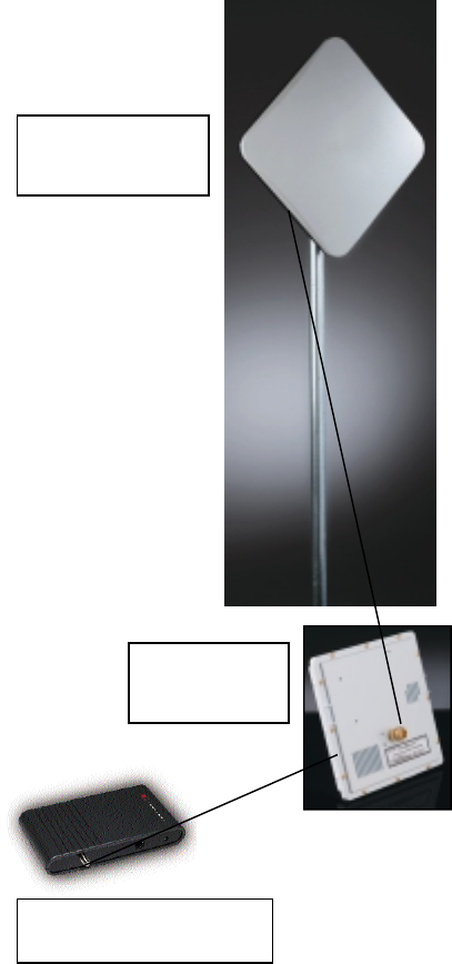
Transceiver
Planar Array
Antenna
Cable Modem