CalAmp 520005-1 MDS-MMDS Transceiver, Model 520005-1 User Manual installation guide
CalAmp Corp. MDS-MMDS Transceiver, Model 520005-1 installation guide
UserManual.wiki
>
CalAmp
>
520005-1 User Manual
>
installation guide
Contents
1.
Page one of installation instructions
2.
Page two of installation instructions
3.
Instruction guide
4.
standalone guide pg 1
5.
standalone guide pg2
6.
planar guide pg 1
7.
planar guide pg 2
8.
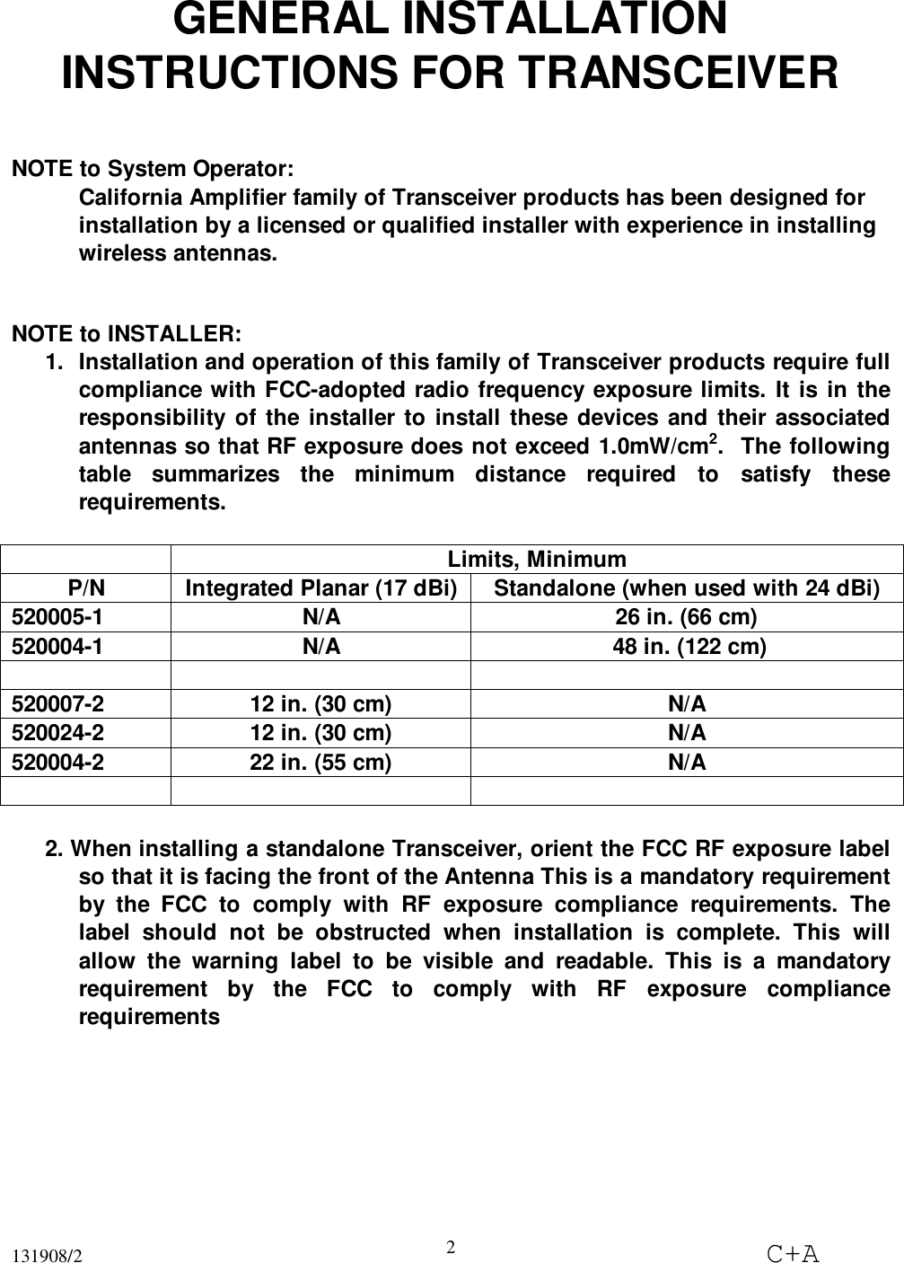
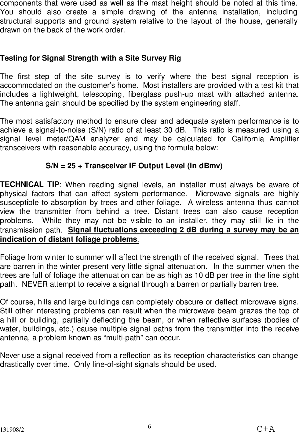
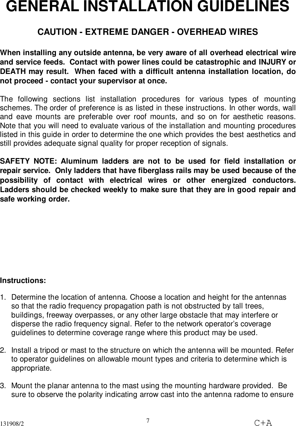
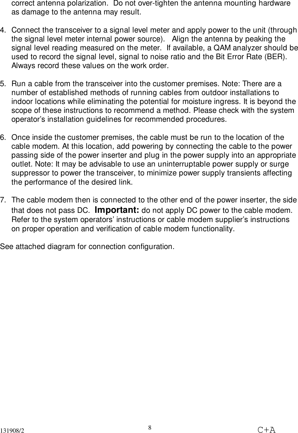
installation guide
installation guide
Navigation menu
Upload a User Manual
Namespaces
Wiki Guide
HTML
PDF
Info
Views
User Manual
Discussion / Help
Navigation