CalAmp 55BTW Broadband router to enable wireless data connectivity. User Manual Vanguard Series Fixed Quick Start Guide

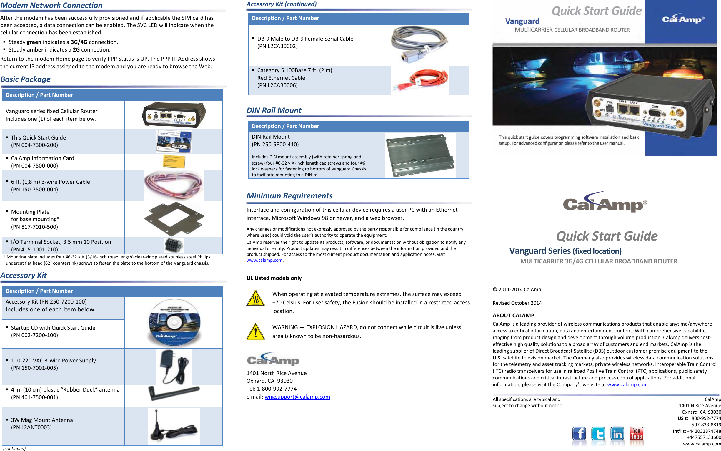
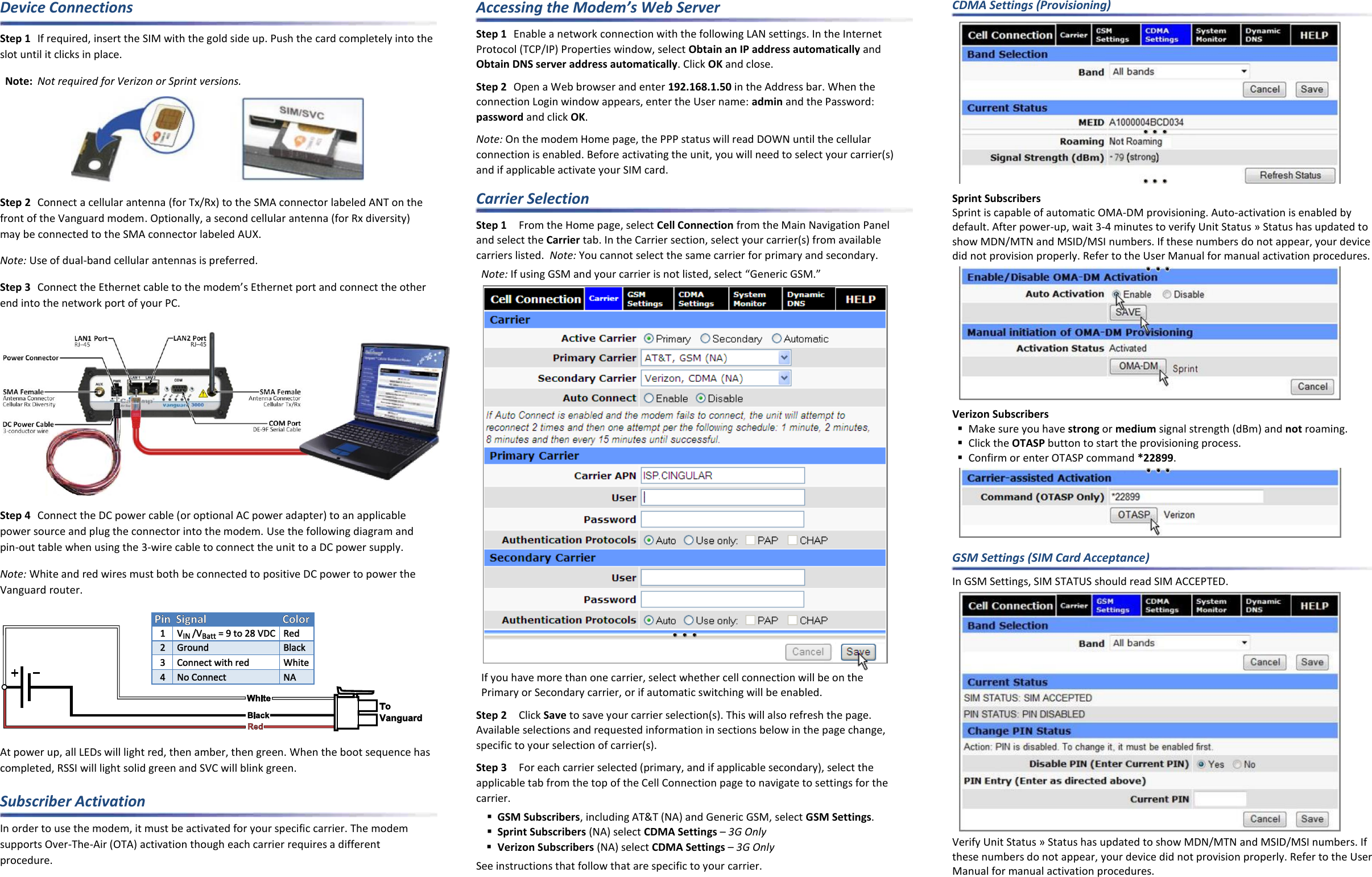
CalAmp Broadband router to enable wireless data connectivity. Vanguard Series Fixed Quick Start Guide

Contents

User Manual I

Modem Network Connection After the modem has been successfully provisioned and if applicable the SIM card has been accepted, a data connection can be enabled. The SVC LED will indicate when the cellular connection has been established.  Steady green indicates a 3G/4G connection.  Steady amber indicates a 2G connection. Return to the modem Home page to verify PPP Status is UP. The PPP IP Address shows the current IP address assigned to the modem and you are ready to browse the Web. Basic Package Description / Part Number  Vanguard series fixed Cellular Router Includes one (1) of each item below.   This Quick Start Guide (PN 004-7300-200)   CalAmp Information Card (PN 004-7500-000)   6 ft. (1,8 m) 3-wire Power Cable (PN 150-7500-004)   Mounting Plate  for base mounting* (PN 817-7010-500)   I/O Terminal Socket, 3.5 mm 10 Position  (PN 415-1001-210)  * Mounting plate includes four #6-32 × ¼ (3/16-inch tread length) clear-zinc plated stainless steel Philips undercut flat head (82° countersink) screws to fasten the plate to the bottom of the Vanguard chassis. Accessory Kit Description / Part Number  Accessory Kit (PN 250-7200-100) Includes one of each item below.   Startup CD with Quick Start Guide (PN 002-7200-100)  110-220 VAC 3-wire Power Supply (PN 150-7001-005)   4 in. (10 cm) plastic “Rubber Duck” antenna (PN 401-7500-001)   3W Mag Mount Antenna (PN L2ANT0003)  (continued) Accessory Kit (continued) Description / Part Number   DB-9 Male to DB-9 Female Serial Cable (PN L2CAB0002)   Category 5 100Base 7 ft. (2 m)  Red Ethernet Cable (PN L2CAB0006)   DIN Rail Mount Description / Part Number  DIN Rail Mount  (PN 250-5800-410)   Includes DIN mount assembly (with retainer spring and screw) four #6-32 × ¼-inch length cap screws and four #6 lock washers for fastening to bottom of Vanguard Chassis to facilitate mounting to a DIN rail.   Minimum Requirements Interface and configuration of this cellular device requires a user PC with an Ethernet interface, Microsoft Windows 98 or newer, and a web browser. Any changes or modifications not expressly approved by the party responsible for compliance (in the country where used) could void the user’s authority to operate the equipment. CalAmp reserves the right to update its products, software, or documentation without obligation to notify any individual or entity. Product updates may result in differences between the information provided and the product shipped. For access to the most current product documentation and application notes, visit www.calamp.com.  UL Listed models only  When operating at elevated temperature extremes, the surface may exceed +70 Celsius. For user safety, the Fusion should be installed in a restricted access location.  WARNING — EXPLOSION HAZARD, do not connect while circuit is live unless area is known to be non-hazardous.   1401 North Rice Avenue Oxnard, CA  93030 Tel: 1-800-992-7774 e mail: wngsupport@calamp.com           Quick Start Guide Vanguard Series (fixed location) MULTICARRIER 3G/4G CELLULAR BROADBAND ROUTER  © 2011-2014 CalAmp   Revised October 2014 ABOUT CALAMP CalAmp is a leading provider of wireless communications products that enable anytime/anywhere access to critical information, data and entertainment content. With comprehensive capabilities ranging from product design and development through volume production, CalAmp delivers cost-effective high quality solutions to a broad array of customers and end markets. CalAmp is the leading supplier of Direct Broadcast Satellite (DBS) outdoor customer premise equipment to the U.S. satellite television market. The Company also provides wireless data communication solutions for the telemetry and asset tracking markets, private wireless networks, Interoperable Train Control (ITC) radio transceivers for use in railroad Positive Train Control (PTC) applications, public safety communications and critical infrastructure and process control applications. For additional information, please visit the Company’s website at www.calamp.com.  All specifications are typical and subject to change without notice.  CalAmp 1401 N Rice Avenue Oxnard, CA  93030 US t:  800-992-7774  507-833-8819 Int’l t: +442032874748   +447557133600 www.calamp.com
Device Connections Step 1  If required, insert the SIM with the gold side up. Push the card completely into the slot until it clicks in place. Note: Not required for Verizon or Sprint versions.  Step 2  Connect a cellular antenna (for Tx/Rx) to the SMA connector labeled ANT on the front of the Vanguard modem. Optionally, a second cellular antenna (for Rx diversity) may be connected to the SMA connector labeled AUX. Note: Use of dual-band cellular antennas is preferred. Step 3 Connect the Ethernet cable to the modem’s Ethernet port and connect the other end into the network port of your PC.  Step 4  Connect the DC power cable (or optional AC power adapter) to an applicable power source and plug the connector into the modem. Use the following diagram and pin-out table when using the 3-wire cable to connect the unit to a DC power supply. Note: White and red wires must both be connected to positive DC power to power the Vanguard router.  At power up, all LEDs will light red, then amber, then green. When the boot sequence has completed, RSSI will light solid green and SVC will blink green. Subscriber Activation In order to use the modem, it must be activated for your specific carrier. The modem supports Over-The-Air (OTA) activation though each carrier requires a different procedure. Accessing the Modem’s Web Server Step 1  Enable a network connection with the following LAN settings. In the Internet Protocol (TCP/IP) Properties window, select Obtain an IP address automatically and Obtain DNS server address automatically. Click OK and close. Step 2  Open a Web browser and enter 192.168.1.50 in the Address bar. When the connection Login window appears, enter the User name: admin and the Password: password and click OK. Note: On the modem Home page, the PPP status will read DOWN until the cellular connection is enabled. Before activating the unit, you will need to select your carrier(s) and if applicable activate your SIM card. Carrier Selection Step 1  From the Home page, select Cell Connection from the Main Navigation Panel and select the Carrier tab. In the Carrier section, select your carrier(s) from available carriers listed.  Note: You cannot select the same carrier for primary and secondary. Note: If using GSM and your carrier is not listed, select “Generic GSM.”  If you have more than one carrier, select whether cell connection will be on the  Primary or Secondary carrier, or if automatic switching will be enabled. Step 2  Click Save to save your carrier selection(s). This will also refresh the page. Available selections and requested information in sections below in the page change, specific to your selection of carrier(s). Step 3  For each carrier selected (primary, and if applicable secondary), select the applicable tab from the top of the Cell Connection page to navigate to settings for the carrier.  GSM Subscribers, including AT&T (NA) and Generic GSM, select GSM Settings.  Sprint Subscribers (NA) select CDMA Settings – 3G Only  Verizon Subscribers (NA) select CDMA Settings – 3G Only See instructions that follow that are specific to your carrier. CDMA Settings (Provisioning)  Sprint Subscribers Sprint is capable of automatic OMA-DM provisioning. Auto-activation is enabled by default. After power-up, wait 3-4 minutes to verify Unit Status » Status has updated to show MDN/MTN and MSID/MSI numbers. If these numbers do not appear, your device did not provision properly. Refer to the User Manual for manual activation procedures.  Verizon Subscribers  Make sure you have strong or medium signal strength (dBm) and not roaming.  Click the OTASP button to start the provisioning process.  Confirm or enter OTASP command *22899.   GSM Settings (SIM Card Acceptance) In GSM Settings, SIM STATUS should read SIM ACCEPTED.  Verify Unit Status » Status has updated to show MDN/MTN and MSID/MSI numbers. If these numbers do not appear, your device did not provision properly. Refer to the User Manual for manual activation procedures.

Navigation menu