User Manual

Integration Guide
CMM9900/CMM9920
AMPS Retrofit Converter
(GSM/GPRS Modem Module)
CalAmp M2M Products
2701 Loker Ave West
Suite #110
Carlsbad, CA 92010

CalAmp Integration Guide
AMPS Retrofit Converter CMM9900/CMM9920
1/5/2007 ---CONFIDENTIAL--- 2
Document Changes:
Date Document Revision Details
12/27/2006 0.01 Initial version
01/03/2007 0.02 Revised per engineering inputs

CalAmp Integration Guide
AMPS Retrofit Converter CMM9900/CMM9920
1/5/2007 ---CONFIDENTIAL--- 3
TABLE OF CONTENTS
RF SAFETY WARNING 4
PART 15 NOTICE 5
INTEGRATION GUIDELINES 6
MOUNTING 6
ANTENNA CONSIDERATIONS 10
SHIELDING CONSIDERATIONS 12
RETROFIT INSTALLATION GUIDELINES 15
NETWORK PROVISIONING OF THE CMM9900/CMM9920 15
COPYING THE CONFIGURATION INFORMATION FROM THE ORIGINAL DEVICE 16
REMOVING THE ORIGINAL CMM DEVICE 16
INSTALLING THE CMM99XX RETROFIT ADAPTER 16
VALIDATING THE INSTALLATION 16
APPROVALS 17
PART 15 CERTIFICATION 17
PRODUCT LABELING 18
EQUIPMENT AUTHORIZATION 18
PRODUCT SAFETY WARNING 18
OTHER PRODUCT LABELING REQUIREMENTS 18
APPENDIX A - APPROVED ANTENNA LIST FOR USE WITH CMM9900/CMM9920 19
APPENDIX B - HARDWARE RESOURCES 20

CalAmp Integration Guide
AMPS Retrofit Converter CMM9900/CMM9920
1/5/2007 ---CONFIDENTIAL--- 4
RF SAFETY WARNING
- WARNING -
This device and associated antenna must be installed in a location at least
30cm from the body of the user or other nearby persons in order to comply
with the FCC RF exposure guidelines.
- NOTICE -
To comply with RF Exposure and FCC Regulations (CFR 47 Parts 22H &
24E) these devices must be used with an approved antenna system. The
total antenna system gain must not exceed that of the original approved
configuration. This transmitter module is restricted to mobile or fixed
installations. The antenna(s) used for this transmitter must be installed to
provide a separation distance of at least 30 cm from all persons and must
not be co-located or operating in conjunction with any other transmitter.
Portable operation within 30 cm of a person’s body is not allowed.”
IMPORTANT!!
Performance and compliance with FCC rules are heavily influenced by final
packaging and antenna configuration of the end-product. Installations not
complying with the 30cm minimum separation requirement, using
substantially different antenna configurations from those described herein,
or utilizing operating voltages outside of the normal specifications must be
evaluated for compliance with FCC Rules and RF exposure requirements.
Responsibility for compliance of the final product is the responsibility of
the end-product manufacturer.
The CMM9900/9920 may only be used with antennas specifically approved
for use with this product and included in the FCC and PTCRB approvals for
this product.
- WARNING -
Use of antenna types other than those included on the CMM9900/9920 FCC
Equipment Authorizations may invalidate the FCC and PTCRB approvals
for this product. See the appendix in the back of this document for a
current list of approved antennas.

CalAmp Integration Guide
AMPS Retrofit Converter CMM9900/CMM9920
1/5/2007 ---CONFIDENTIAL--- 5
Refer to the following resources for additional information regarding FCC rules and RF Safety
Guidelines for this type of devices:
47CFR Part 22H
47CFR Part 24E
47CFR Part 1.1307 – 1.1310
47CFR Part 2.1091, 2.1093
Federal Communications Commission (FCC) Primary website:
www.fcc.gov
Federal Communications Commission Office of Engineering and Technology web site:
www.fcc.gov/oet/rfsafety
PART 15 NOTICE
- NOTICE -
This device complies with Part 15 of the FCC rules. Operation is subject
to the following two conditions: (1) This device may not cause harmful
interference, and (2) this device must accept any interference received,
including interference that may cause undesired operation.
This equipment has been tested and found to comply with the limits for a Class B digital
device, pursuant to part 15 of the FCC Rules. These limits are designed to provide
reasonable protection against harmful interference in a residential installation. This
equipment generates, uses and can radiate radio frequency energy and, if not installed
and used in accordance with the instructions, may cause harmful interference to radio
communications. However, there is no guarantee that interference will not occur in a
particular installation. If this equipment does cause harmful interference to radio or
television reception, which can be determined by turning the equipment off and on, the
user is encouraged to try to correct the interference by one or more of the following
measures:
o Reorient or relocate the receiving antenna.
o Increase the separation between the equipment and receiver.
o Connect the equipment into an outlet on a circuit different from that to which the
receiver s connected.
o Consult the dealer or an experienced radio/TV technician for help.

CalAmp Integration Guide
AMPS Retrofit Converter CMM9900/CMM9920
1/5/2007 ---CONFIDENTIAL--- 6
INTEGRATION GUIDELINES
The following guide is designed to provide the developer/integrator additional information
regarding hardware considerations. The sections include detailed design ideas along with tips
and tricks we have used in implementing various applications. Each section has a brief
description and diagrams to assist you in your planning stages with the CMM9900/CMM9920.
MOUNTING
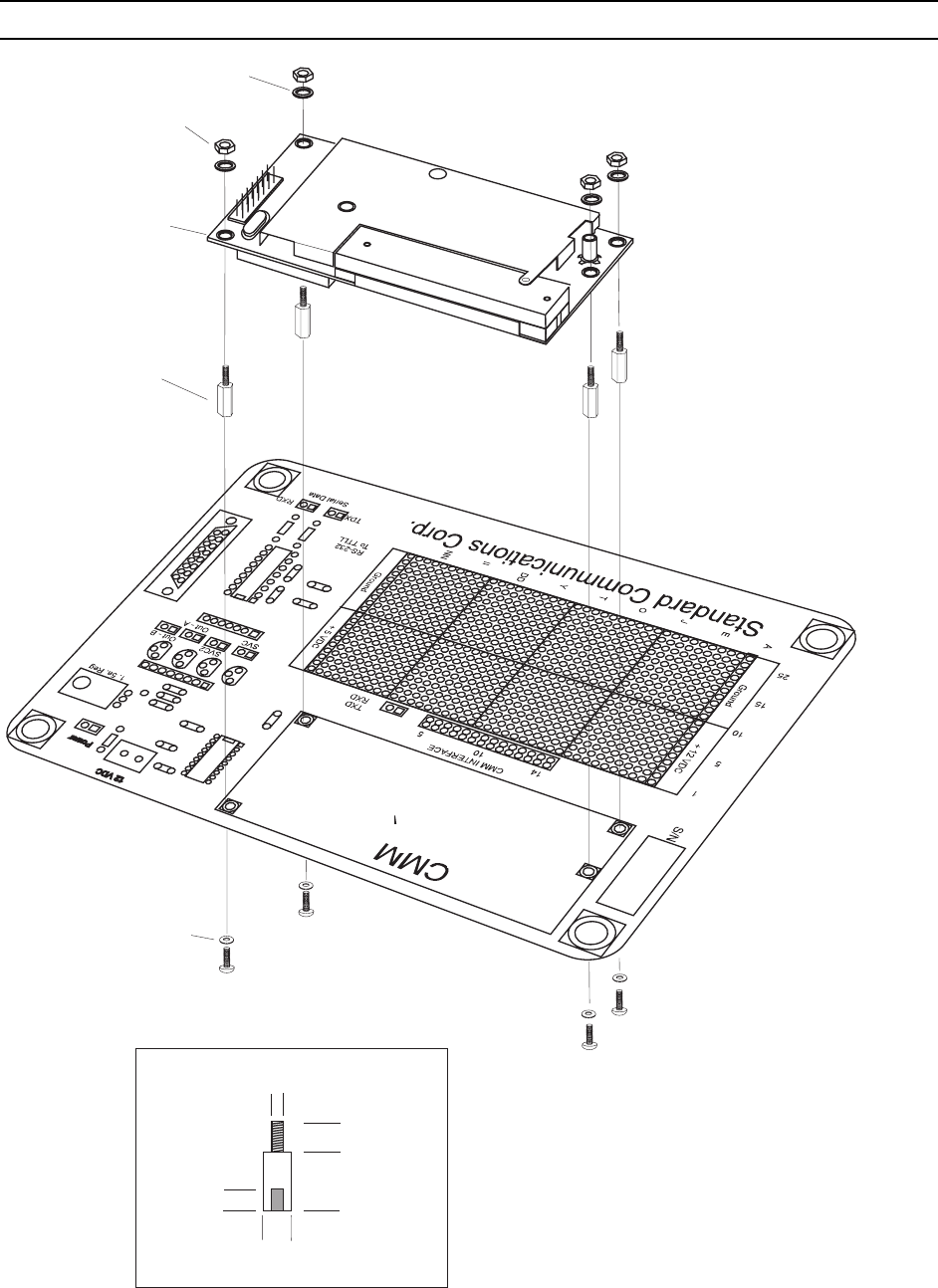
The CMM9900/CMM9920 has four mounting holes arranged in the pattern shown in figure 1.
If stand-offs are to be used, metal type is the recommended due to added ground potential. In
figure 1, the stand-offs set the CMM9900/CMM9920 unit slightly higher than the host PCB. An
air gap is not necessary but will allow for PCB to PCB isolation and noise immunity. The
standoff used on the evaluation PCB is exaggerated to display the CMM9900/CMM9920. The
height of these stand-offs are not necessarily ideal and space can be greatly conserved by
using shorter ones.
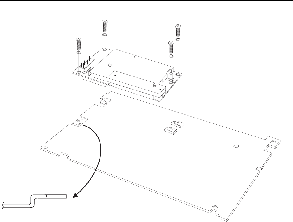
Figure 2. Shows an example of a plate shield already used on an application with the
modification of bent tabs to allow for mounting of the CMM9900/CMM9920. This is a relatively
inexpensive method of mounting and can be implemented easily when the plate is initially
punched. Care should be taken so that the tabs do not extend past the flash area of the
mounting holes.
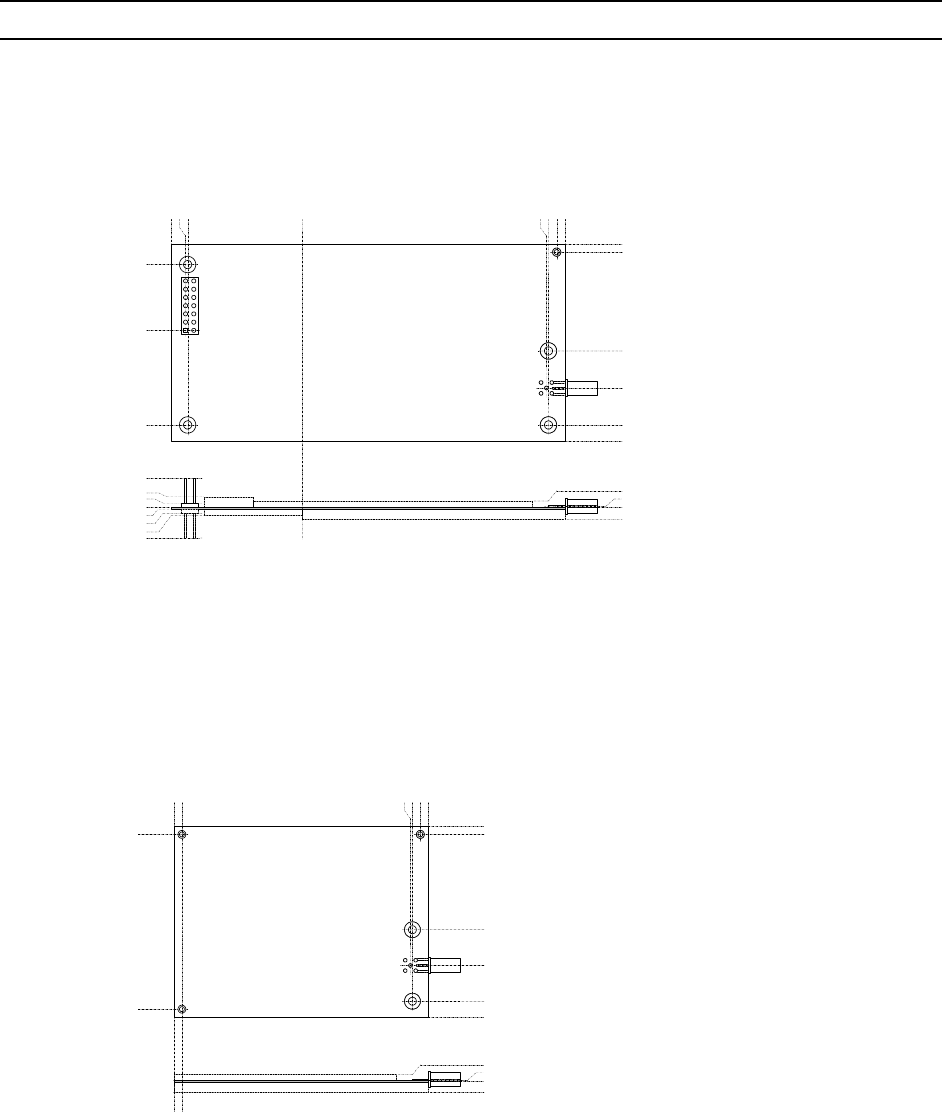
Figures 3 and 4. Shows the mechanical drawing of the CMM9900/CMM9920 units. These
dimensions should be used for mounting and placement purposes. The drawing is illustrated
from the bottom side perspective. The antenna and interface connectors are located on the
topside of the PCB.
CalAmp Integration Guide
AMPS Retrofit Converter CMM9900/CMM9920
1/5/2007 ---CONFIDENTIAL--- 7
Standoff
(See Detail)
CU81K PCB
Nut
Washer
7728b
4/40
(3.0 mm)
Min 0.15" (3 mm)
Min 0.250" (6 mm)
0.15" (3 mm)
0.250"
(6 mm)
Washer
Figure 1. Mounting Details
CalAmp Integration Guide
AMPS Retrofit Converter CMM9900/CMM9920
1/5/2007 ---CONFIDENTIAL--- 8
7733A
DETAIL
Figure 2. Sheet Metal Tab Detail
CalAmp Integration Guide
AMPS Retrofit Converter CMM9900/CMM9920
1/5/2007 ---CONFIDENTIAL--- 9
39.5 41.5
86.5
37.0
17.0
0.00
-1.5
0.00
83.0
1.0
0.00
-1.5
-3.5
39.5
17.0
10.0
0.00
-3.5
0.00
0.5
3.0
0.00
8.0
-9.0
-2.5
1.5
5.0
-4.0
-6.0
56.5
-1.0
Figure 3. CMM9900 Dimensions
39.5 41.5
-1.5
1.0
0.00
-1.5
-3.5
39.5
17.0
10.0
0.00
-3.5
0.00
0.5
3.0
-6.0
56.5
54.5
Figure 4. CMM9920 Dimensions

CalAmp Integration Guide
AMPS Retrofit Converter CMM9900/CMM9920
1/5/2007 ---CONFIDENTIAL--- 10
ANTENNA CONSIDERATIONS
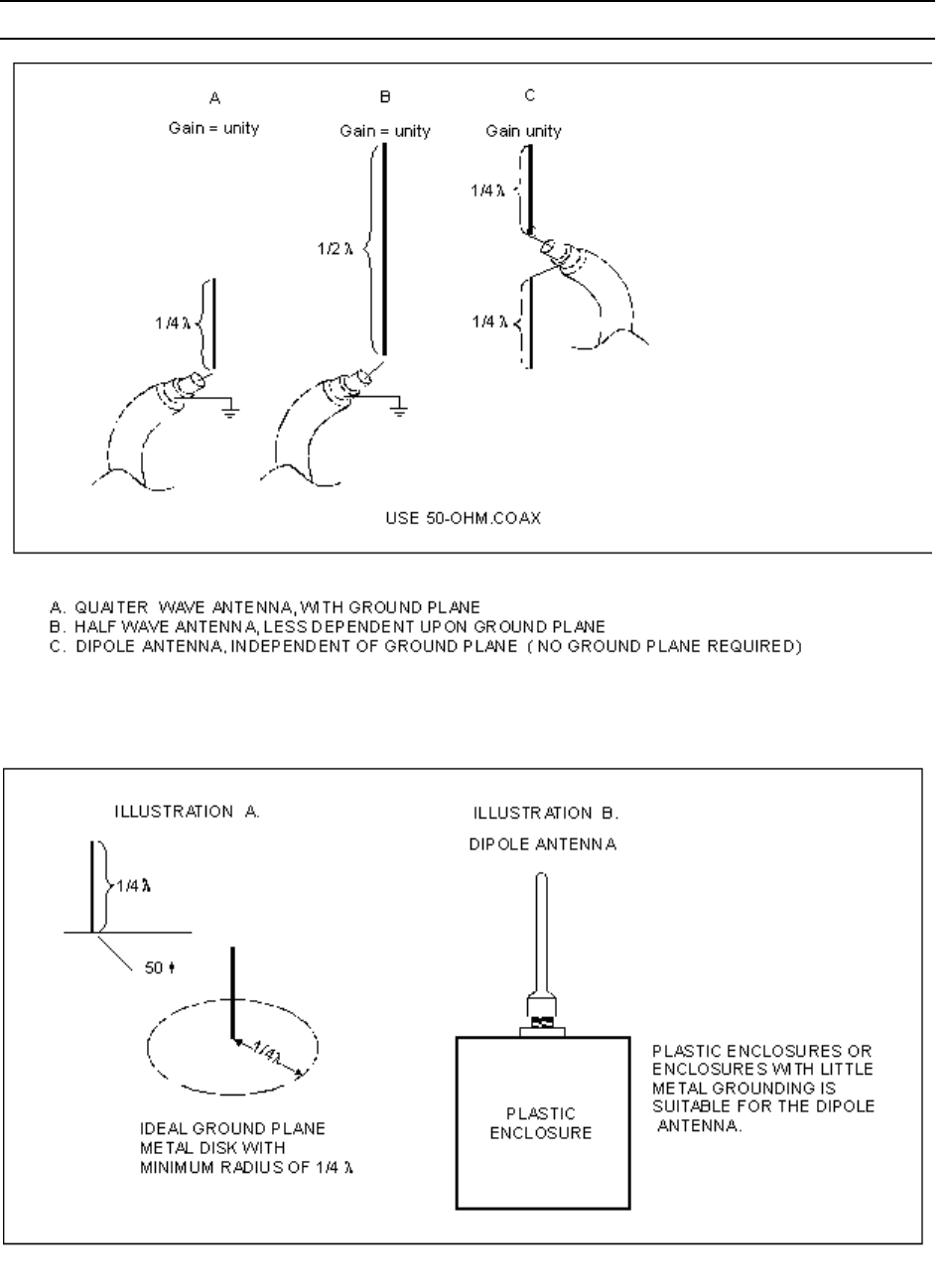
The diagrams below illustrate the different antenna selections used for applications. Each
example has implementation criteria due to its performance and operation.
A. The quarter wave antenna is small and lends itself well into tight applications where space is
critical. A ground plane radius of greater than 100mm is required for proper operation. Failure to
provide this grounding will result in erratic radiation patterns, signal loss and mismatched
impedance to the CMM9900/CMM9920.
B. The half wave antenna is twice the length of the quarter wave. It’s properties require less
ground plane which make it more ideal for applications that have less metal mass. The antenna
has a better radiation pattern.
C. The dipole antenna provides a ground-plane-free operation with optimum gain for its size.
This antenna provides its own ground-radiating element and can be used with plastic
enclosures.
WARNING
Use of antenna types other than those included on the CMM9900/9920 FCC
Equipment Authorizations may invalidate the FCC and PTCRB approvals
for this product. See the appendix in the back of this document for a
current list of approved antennas.
CalAmp Integration Guide
AMPS Retrofit Converter CMM9900/CMM9920
1/5/2007 ---CONFIDENTIAL---
11

CalAmp Integration Guide
AMPS Retrofit Converter CMM9900/CMM9920
1/5/2007 ---CONFIDENTIAL---
12
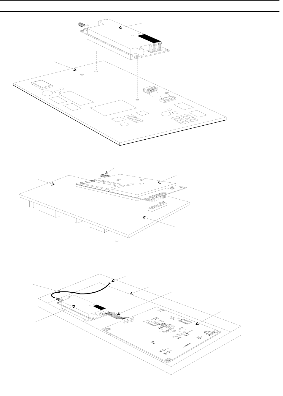
SHIELDING CONSIDERATIONS
When planning the PCB layout for an application some design rules and layout plans should be
considered. The following diagrams show various mounting configurations with respect to
shielding. Often the application PCB does not allow for separate ground plane implementation.
In these cases a list of design rules should be used in order to prevent inter-circuit problems.
The last section of this document deals with common design practices used with RF module
implementations.
CalAmp Integration Guide
AMPS Retrofit Converter CMM9900/CMM9920
1/5/2007 ---CONFIDENTIAL---
13
ANTENNA PORT
SHIELD
RIBBON CABLE
CMM
UNIT
RF CABLE
APPLICATION PCA
ANTENNA PORT
CMM UNIT
SOLID
COPPER
POUR
CMM UNIT MOUNTED
UPSIDE DOWN WITH
FEMALE INTERFACE
CONNECTOR USED
PCB
BACKPLANE
CMM UNIT
SOLID
COPPER
POUR
CMM UNIT MOUNTED
WITH INTERFACE
CONNECTOR ON TOP,
USING RIBBON CONNECTOR
CABLE FOR INTERFACE
CalAmp Integration Guide
AMPS Retrofit Converter CMM9900/CMM9920
1/5/2007 ---CONFIDENTIAL---
14
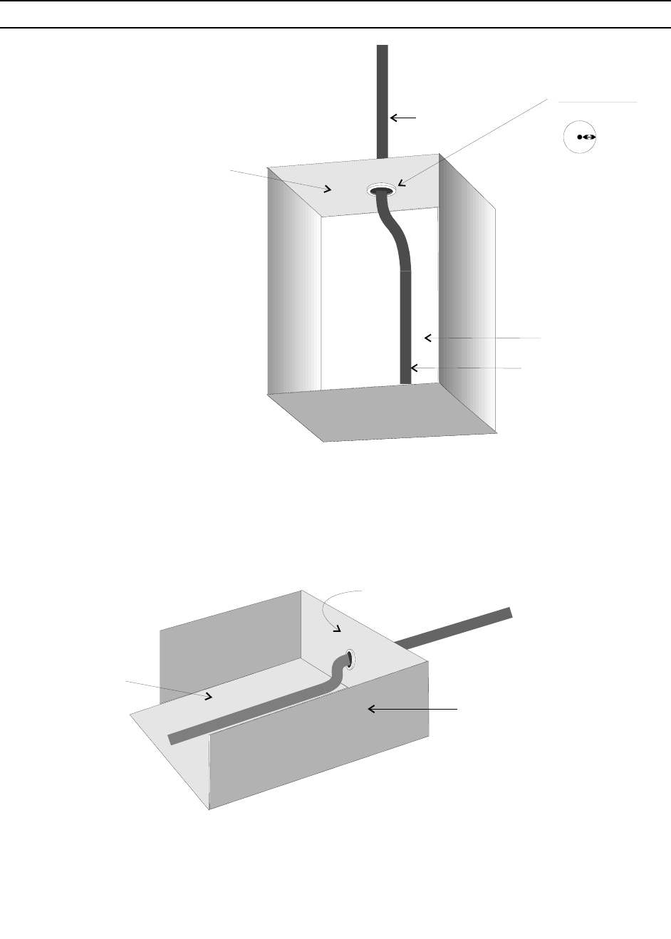
INSIDE
VIEW
GROUND PLANE
MADE OF THIN
SHEET METAL
OR COPPER FOIL
ANTENNA
ANTENNA PLACEMENT AND GROUND PLANE EXAMPLES
RF SHIELD
COATING
PLASTIC OR
NON-CONDUCTIVE
ENCLOSURE USED.
PLASTIC OR
NON-CONDUCTIVE
ENCLOSURE
COAX
RF COAX CABLE
RF COAX CABLE
100 mm
MIN DETAIL
SEE DETAIL

CalAmp Integration Guide
AMPS Retrofit Converter CMM9900/CMM9920
1/5/2007 ---CONFIDENTIAL---
15
RETROFIT INSTALLATION GUIDELINES
The CMM9900 and CMM9920 are designed to be ‘drop-in’ replacements for the legacy CMM
products. This means that no modification to the hardware or software of the application device
is necessary in order to install and operate the CMM99xx in place of the legacy CMM device.
(With the exception of the replacement of the CMM device, and possibly the antenna.)
There are however, some specific steps necessary in order to successfully complete the
process of installation into an existing application device. The following guidelines will describe
the process of installing the CMM9900 or CMM9920 into existing CMM-based applications:
NETWORK PROVISIONING OF THE CMM9900/CMM9920
The CMM9900 and CMM9920 must be provisioned for operation on the GSM network before
they access the network to send and receive data. The CMM99xx devices receive the majority
of their network provisioning information through the installation of a GSM SIM card onto the
module. The installation of the SIM card onto the CMM99xx module must be completed prior to
installation of the module into the application device.
There is also additional information that must be provided to the module in order to finalize the
provisioning process and allow communication of data through the Control Channel Network
Server via SMS and/or GPRS. This information may include some or all of the following:
• Original Primary MIN number
• Any secondary MIN number(s) used
• Electronic Serial Number(ESN) of original CMM module
• SMS address for Control Channel Network Server
• Control Channel Network Server IP address for GPRS data
• APN for GPRS data
Default values for SMS address, Control Channel Network Server IP address, and APN are pre-
loaded into the device based upon the type of Control Channel Network at time of installation
configuration. These values may updated manually via the serial interface or over-the-air if they
require changes in the future.

CalAmp Integration Guide
AMPS Retrofit Converter CMM9900/CMM9920
1/5/2007 ---CONFIDENTIAL---
16
COPYING THE CONFIGURATION INFORMATION FROM THE ORIGINAL DEVICE
The configuration information from the original CMM device is necessary for the CMM99xx to
properly communicate the data back to the network server and function transparently.
Refer to the Sections following for specific information regarding removal, installation and
validation.
REMOVING THE ORIGINAL CMM DEVICE
The original CMM device should be removed using procedures appropriate for the specific
application device. Power should always be removed from both the application device and the
CMM device prior to conducting any installation, or removal of the CMM device.
Special care should be taken not to damage the application unit or the original CMM device.
(Further operation of the original CMM module may be required in order to copy the
configuration data for loading onto the new CMM99xx module.)
WARNING
Precautions must be taken whenever handling the CMM to protect the electronic circuitry of
both the CMM module and the application device from damage due to static discharge (ESD).
INSTALLING THE CMM99xx RETROFIT ADAPTER
The CMM99xx device should be installed using procedures appropriate for the specific
application device. This will normally be the same, or very similar, procedure to that used for
installation of the original CMM device.
If the existing antenna connected to the application device is not an approved antenna, it should
be removed and replaced with an approved antenna prior to re-applying power to the unit.
VALIDATING THE INSTALLATION
Validation of the CMM99xx installation should be conducted to confirm successful installation of
the device and that the application device is still functioning properly. Validation testing should
also confirm that all necessary configuration and identity information has been programmed into
the CMM99xx device.

CalAmp Integration Guide
AMPS Retrofit Converter CMM9900/CMM9920
1/5/2007 ---CONFIDENTIAL---
17
APPROVALS
The CMM9900 and CMM9920 have been approved as complete GSM Modem type devices.
The FCC, Industry Canada, PTCRB and carrier approvals have all been completed with the
CMM99xx as a final finished product. With the exception of Part 15, no further testing or
certifications should be necessary for the final application, provided that an approved antenna
configuration is used in that application.
The following approvals have been secured (or are in-process) for the CMM99xx products:
• FCC Equipment Authorization (type approval)
• FCC Part 15 Class B
• Industry Canada Equipment Authorization
• PTCRB Approval
• Cingular Approval
• Aeris.net Approval
• Numerex Approval
- WARNING -
The CMM99xx device must be used with an antenna system that is included in the
CMM99xx approval files. Use of an unapproved antenna system in the end application
will make these approvals invalid in that application. Applications requiring the use of an
antenna system not currently on the approved list will require either (1) Re-testing and
updated approvals to add that antenna to the CMM9900 list of approved antenna
systems; or (2) New approvals under the customer name.
PART 15 CERTIFICATION
The CMM9900 and CMM9920 have been certified to meet the requirements of Part 15 of the
FCC Rules as a Class B device. This certification only applies to the CMM99xx unit itself. Once
installed into an application device, responsibility for Part 15 compliance becomes the
responsibility of the manufacturer/provider of the end-product (application).
The environment within the application device includes other potential sources of radio
frequency (RF) interference in addition to the CMM99xx. These potential sources include such
items as crystal oscillator(s), digital address/data lines, switching power supplies, and other
circuitry.
All application devices subject to Part 15 of the FCC rules must be retested and certified to be in
compliance with the rules. This retesting and certification is the responsibility of the customer.

CalAmp Integration Guide
AMPS Retrofit Converter CMM9900/CMM9920
1/5/2007 ---CONFIDENTIAL---
18
PRODUCT LABELING
EQUIPMENT AUTHORIZATION
The labeling of the CMM99xx devices includes certain identifying information that must be
visible in the final end-product (application). If the label of the CMM99xx device is not clearly
visible from the exterior of the end product, then the exterior labeling of the end product must
include information referring to the enclosed transmitter module. This exterior label can use
wording such as the following: “Contains Transmitter Module FCC ID: APVCMM9900, IC: 363A-
CMM9900” or “Contains FCC ID: APVCMM9900, IC: 363A-CMM9900”
- WARNING -
Proper labeling of the device is a mandatory requirement for approval of these devices.
Failure to properly label the application device will invalidate all device approvals and
may subject the end-product manufacturer to sanctions and/or fines.
PRODUCT SAFETY WARNING
The following safety warning must be included in the product documentation for the installer and
end-user:
“To comply with RF Exposure and FCC Regulations (CFR 47 Parts 22H & 24E) this device must
only be used with antenna systems approved for use with this device. The total antenna system
gain must not exceed that of the original approved configuration. This transmitter module is
restricted to mobile or fixed installations. The antenna(s) used for this transmitter must be installed
to provide a separation distance of at least 30 cm from all persons and must not be co-located or
operating in conjunction with any other transmitter. Portable operation within 30 cm of a person’s
body is not allowed.”
It is also recommended that a caution label or tag be attached to the application device.
- WARNING -
This device and associated antenna must be installed in a location at least
30cm from the body of the user or other nearby persons in order to comply
with the FCC RF exposure guidelines.
OTHER PRODUCT LABELING REQUIREMENTS
Other labeling and/or documentation requirements may also apply to end-product applications
of the CMM9900 and CMM9920. These requirements may include statements related to FCC
Part 15 compliance as well as other regulatory requirements.

CalAmp Integration Guide
AMPS Retrofit Converter CMM9900/CMM9920
1/5/2007 ---CONFIDENTIAL---
19
APPENDIX A - APPROVED ANTENNA LIST FOR USE WITH CMM9900/CMM9920
The following is a list of antennas approved for use with the CMM9900 and CMM9920.
Customers are strongly encouraged to use antennas already included on this list in order to
expedite their time to market.
Manufacturer
Mfg Model /
Part Number Type Gain (dBi)
Jinchang Electron GSM-JC000 SMA Flex 3
Jinchang Electron GSM-JC001 Mag w/SMA cable 3.5
JEMA; Japan Electronic Manufacturers, Inc. JA-800-CSMA Sleeve Dipole SMA 2
Hustler CMT-800SMA 5/8 Mag w/SMA cable 3.2
The use of antennas other than those specifically approved for use with these devices may
invalidate the FCC and PTCRB approvals for these devices. Contact CalAmp M2M Application
Engineering for assistance with antenna selection and further information on approvals and use
of other antennas.

CalAmp Integration Guide
AMPS Retrofit Converter CMM9900/CMM9920
1/5/2007 ---CONFIDENTIAL---
20
APPENDIX B - HARDWARE RESOURCES
The following is a partial list of hardware manufacturers providing various components which
may be utilized in various applications of the CMM99xx. The sources are kept as current as
possible, but changes in the product line offered by the manufacturers occur often. Please
contact these companies directly for their latest product information and specs.
Antennas
Company Products offered Telephone #
Ace Technology Fixed and portable antennas 818-718-1534
http://www.aceteq.com
Antenna Specialist / Mobile portable & base antennas 800-664-5274
Allen Telecom Group
www.allentele.com
Astron Wireless Fixed, “DISC”, “Hemi” antennas 703-450-5517
Technologies
www.astronwireless.com
Centurion International Fixed and portable antennas 800-228-4563
www.centurion.com and batteries.
MAXRAD Fixed and Mobile antennas 800-323-9122
www.maxrad.com
Cables
Company Products offered Telephone #
Richardson Electronics RF connectors and cable assy’s 800-737-6937
www.rfpowernet.com
RF Industries RF cable assemblies 800-233-1728
www.rfcables.com
Emerson Network Power RF connectors + hardware 800-247-8256
(formerly Johnson)
http://www.emersonnetworkpower.com/connectivity
Samtec Headers, PCB interconnect 800-726-8329
www.samtec.com solutions. RF Connectors and
assemblies.

CalAmp Integration Guide
AMPS Retrofit Converter CMM9900/CMM9920
1/5/2007 ---CONFIDENTIAL---
21
Connectors
Company Products offered Telephone #
Digi-Key Corporation Mounting hardware / connectors 800-344-4539
www.digikey.com interface cables and components
Emerson Network Power RF connectors + hardware 800-247-8256
(formerly Johnson)
http://www.emersonnetworkpower.com/connectivity
Hirose Electronics PCB interconnect and RF 805-522-7958
http://www.hirose.com connectors and cable assy’s
(60-pin connector for CMM9920)
Richardson Electronics RF connectors and cable assy’s 800-737-6937
www.rfpowernet.com
Samtec Headers, PCB interconnect 800-726-8329
www.samtec.com solutions. RF Connectors and
assemblies.
Miscellaneous
Company Products offered Telephone #
IHS/Global Engineering EIA/TIA/IS-41.1-B, EIA/TIA-553 303-792-2181
Documents Industry standards documents
http://global.ihs.com
RAF Electronic Hardware Stand-offs, chassis fasteners 203-888-2133
http://www.rafhdwe.com