California Eastern Laboratories ZICM357SP2 ZigBee Development Kit User Manual Professional Letter

California Eastern Laboratories ZigBee Development Kit Professional Letter

Contents

  • 1. manual
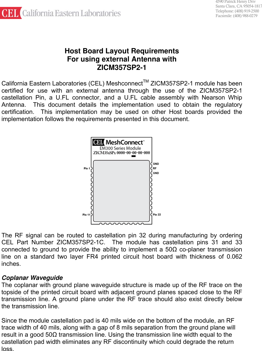
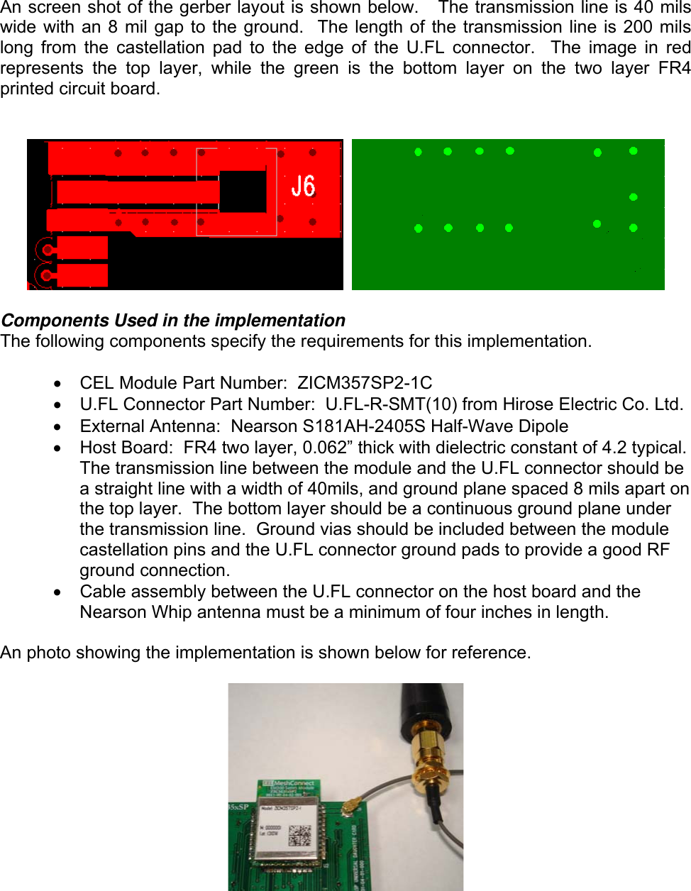
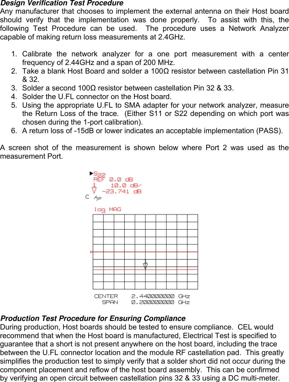
  • 2. external antenna trace instructions

external antenna trace instructions

   4590 Patrick Henry Drive Santa Clara, CA 95054-1817 Telephone: (408) 919-2500 Facsimile: (408) 988-0279 Host Board Layout Requirements For using external Antenna with ZICM357SP2-1   California Eastern Laboratories (CEL) MeshconnectTM ZICM357SP2-1 module has been certified for use with an external antenna through the use of the ZICM357SP2-1 castellation Pin, a U.FL connector, and a U.FL cable assembly with Nearson Whip Antenna.  This document details the implementation used to obtain the regulatory certification.  This implementation may be used on other Host boards provided the implementation follows the requirements presented in this document.     The RF signal can be routed to castellation pin 32 during manufacturing by ordering CEL Part Number ZICM357SP2-1C.  The module has castellation pins 31 and 33 connected to ground to provide the ability to implement a 50Ω co-planer transmission line on a standard two layer FR4 printed circuit host board with thickness of 0.062 inches.  Coplanar Waveguide The coplanar with ground plane waveguide structure is made up of the RF trace on the topside of the printed circuit board with adjacent ground planes spaced close to the RF transmission line. A ground plane under the RF trace should also exist directly below the transmission line.  Since the module castellation pad is 40 mils wide on the bottom of the module, an RF trace width of 40 mils, along with a gap of 8 mils separation from the ground plane will result in a good 50Ω transmission line. Using the transmission line width equal to the castellation pad width eliminates any RF discontinuity which could degrade the return loss.
  An screen shot of the gerber layout is shown below.   The transmission line is 40 mils wide with an 8 mil gap to the ground.  The length of the transmission line is 200 mils long from the castellation pad to the edge of the U.FL connector.  The image in red represents the top layer, while the green is the bottom layer on the two layer FR4 printed circuit board.        Components Used in the implementation The following components specify the requirements for this implementation.  •  CEL Module Part Number:  ZICM357SP2-1C •  U.FL Connector Part Number:  U.FL-R-SMT(10) from Hirose Electric Co. Ltd. •  External Antenna:  Nearson S181AH-2405S Half-Wave Dipole •  Host Board:  FR4 two layer, 0.062” thick with dielectric constant of 4.2 typical.  The transmission line between the module and the U.FL connector should be a straight line with a width of 40mils, and ground plane spaced 8 mils apart on the top layer.  The bottom layer should be a continuous ground plane under the transmission line.  Ground vias should be included between the module castellation pins and the U.FL connector ground pads to provide a good RF ground connection. •  Cable assembly between the U.FL connector on the host board and the Nearson Whip antenna must be a minimum of four inches in length.  An photo showing the implementation is shown below for reference.
  Design Verification Test Procedure Any manufacturer that chooses to implement the external antenna on their Host board should verify that the implementation was done properly.  To assist with this, the following Test Procedure can be used.  The procedure uses a Network Analyzer capable of making return loss measurements at 2.4GHz.  1. Calibrate the network analyzer for a one port measurement with a center frequency of 2.44GHz and a span of 200 MHz. 2.  Take a blank Host Board and solder a 100Ω resistor between castellation Pin 31 & 32. 3.  Solder a second 100Ω resistor between castellation Pin 32 & 33. 4.  Solder the U.FL connector on the Host board. 5.  Using the appropriate U.FL to SMA adapter for your network analyzer, measure the Return Loss of the trace.  (Either S11 or S22 depending on which port was chosen during the 1-port calibration). 6.  A return loss of -15dB or lower indicates an acceptable implementation (PASS).  A screen shot of the measurement is shown below where Port 2 was used as the measurement Port.    Production Test Procedure for Ensuring Compliance During production, Host boards should be tested to ensure compliance.  CEL would recommend that when the Host board is manufactured, Electrical Test is specified to guarantee that a short is not present anywhere on the host board, including the trace between the U.FL connector location and the module RF castellation pad.  This greatly simplifies the production test to simply verify that a solder short did not occur during the component placement and reflow of the host board assembly.  This can be confirmed by verifying an open circuit between castellation pins 32 & 33 using a DC multi-meter.

Navigation menu