Cambium Networks 25601 Wireless Ethernet Bridge User Manual PTP 600 Series User Guide
Cambium Networks Limited Wireless Ethernet Bridge PTP 600 Series User Guide
UserManual.wiki
>
Cambium Networks
>
25601 User Manual
User Manual
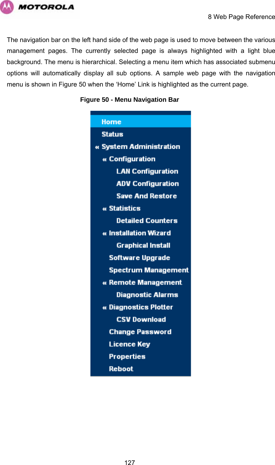
Navigation menu
Upload a User Manual
Namespaces
Wiki Guide
HTML
PDF
Info
Views
User Manual
Discussion / Help
Navigation

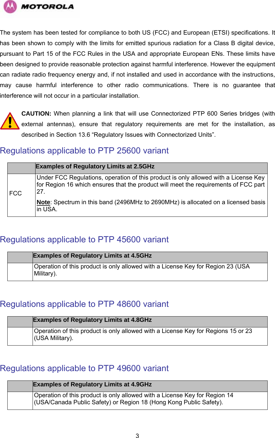
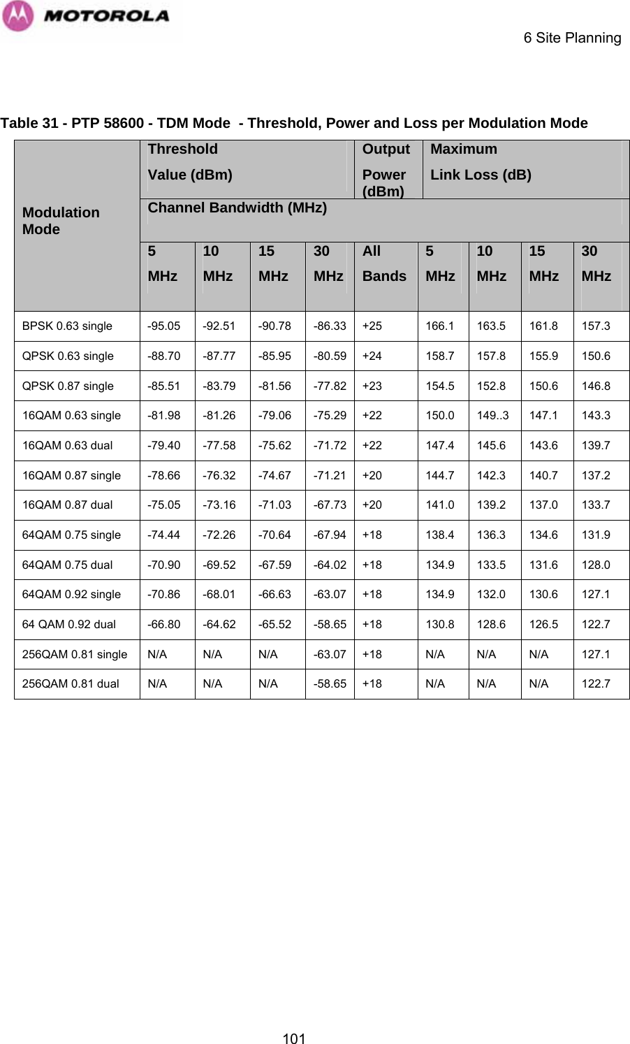
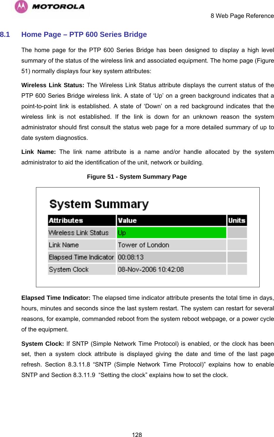
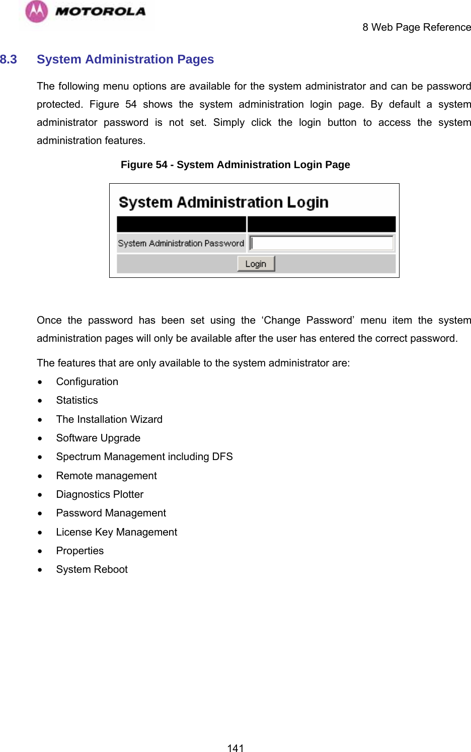
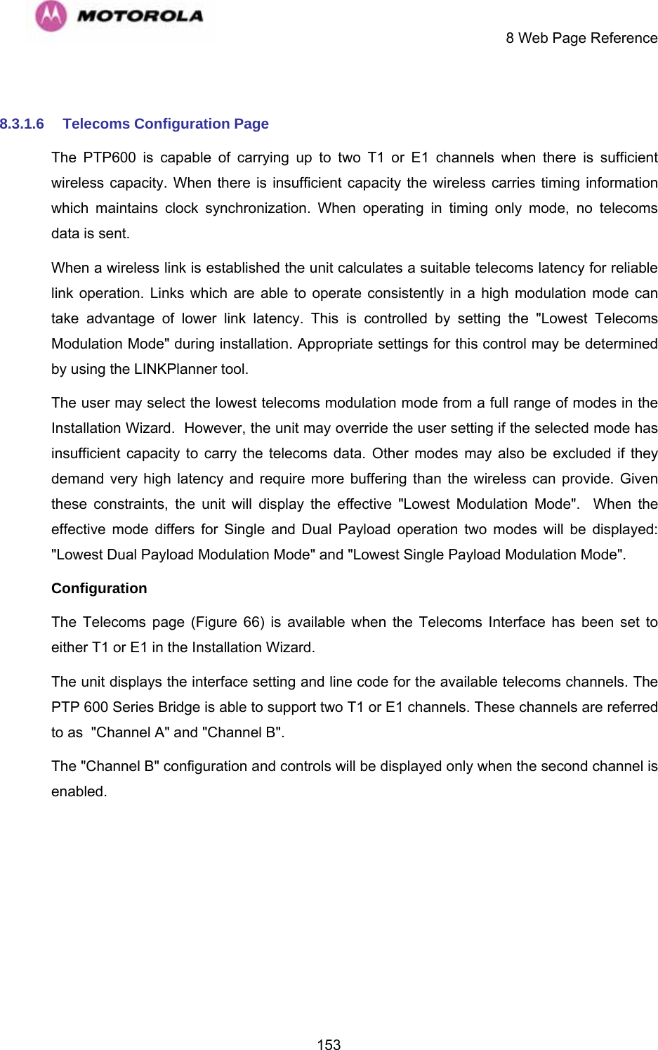
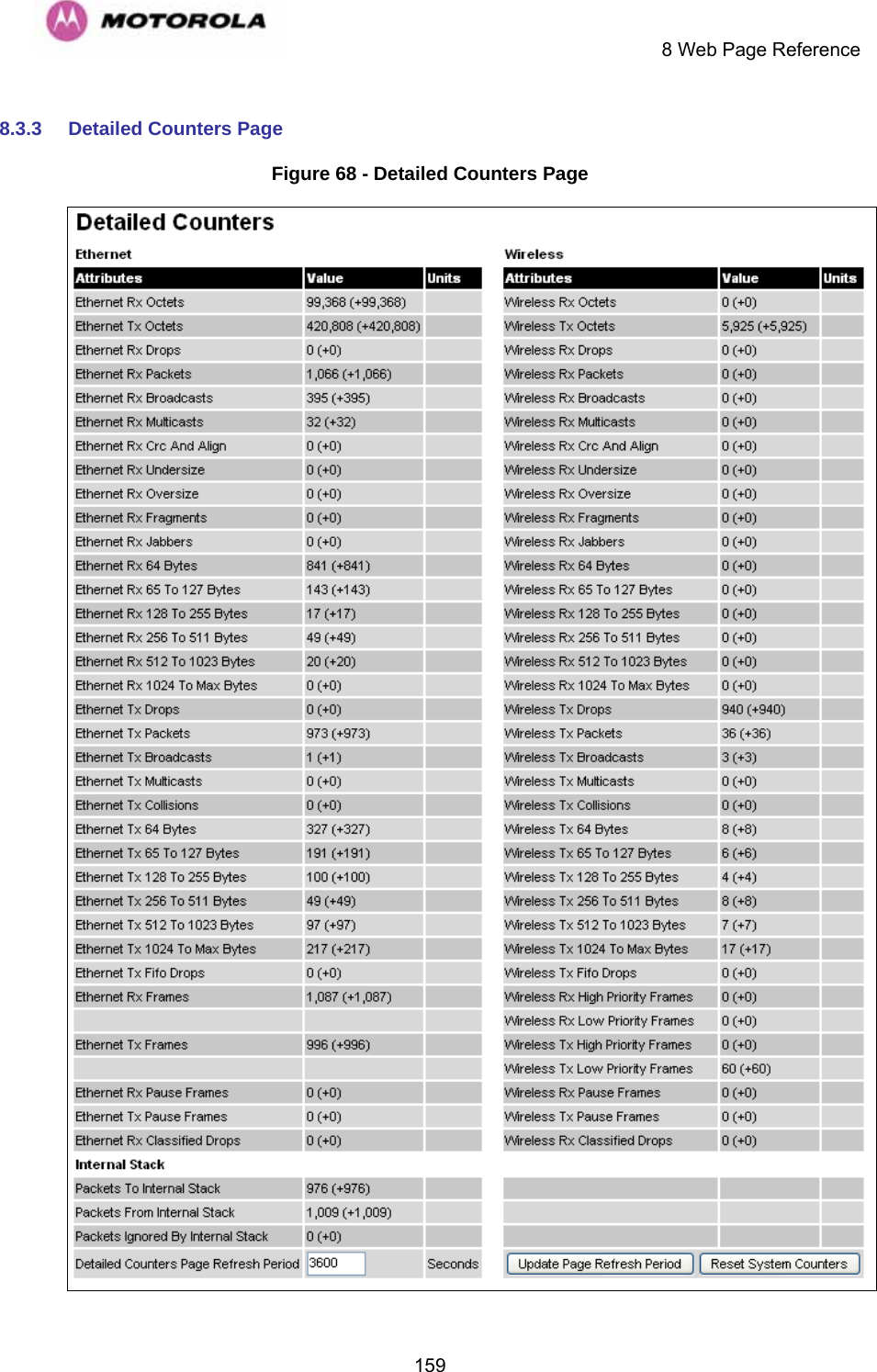
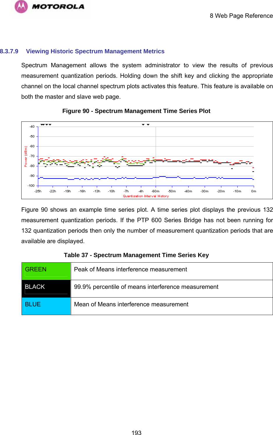
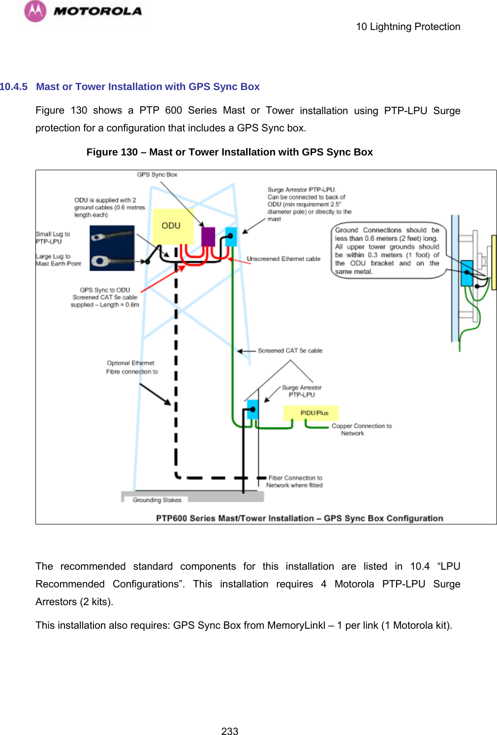
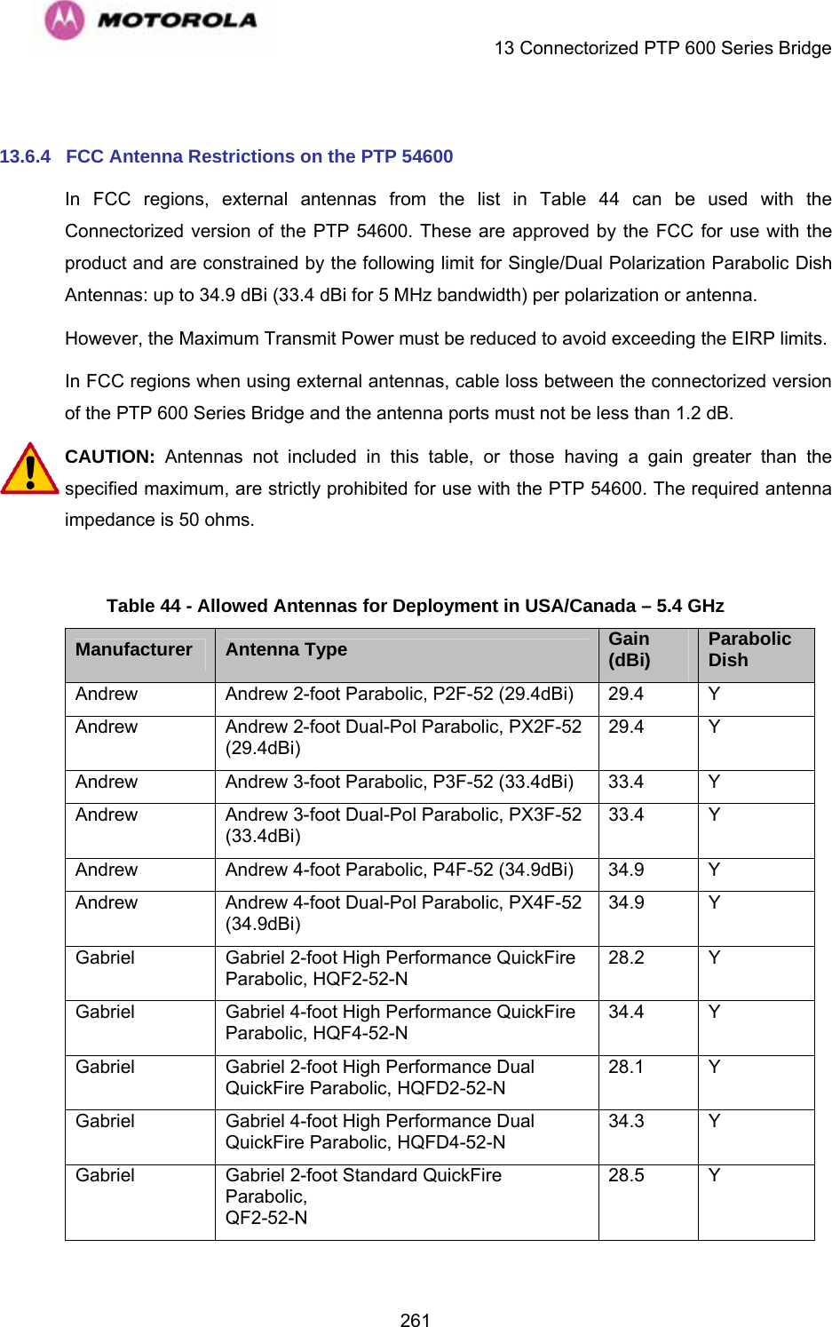
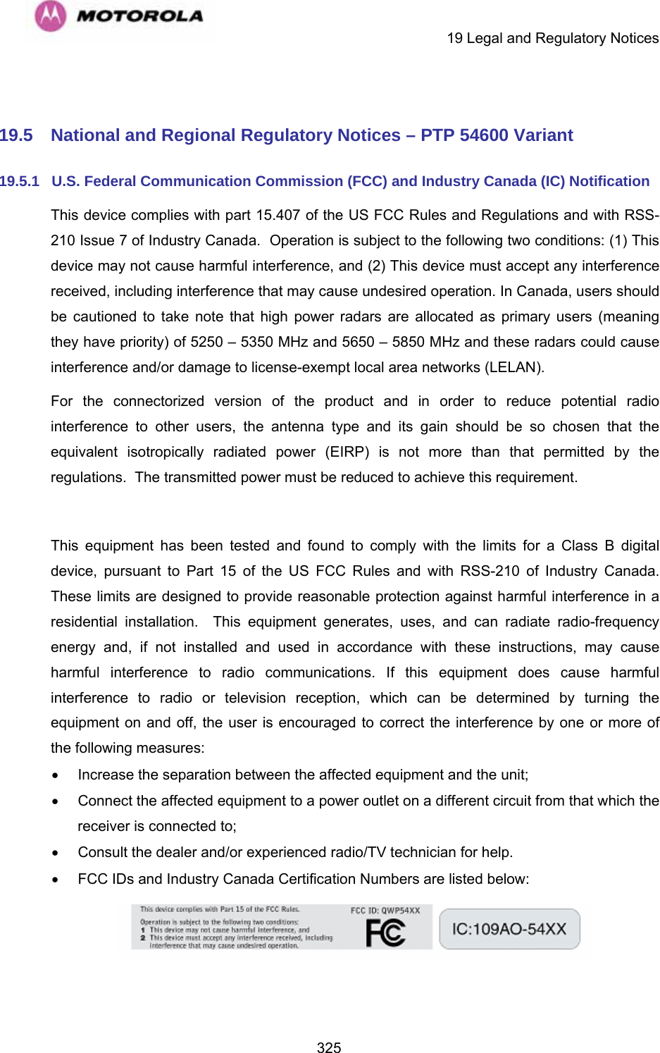
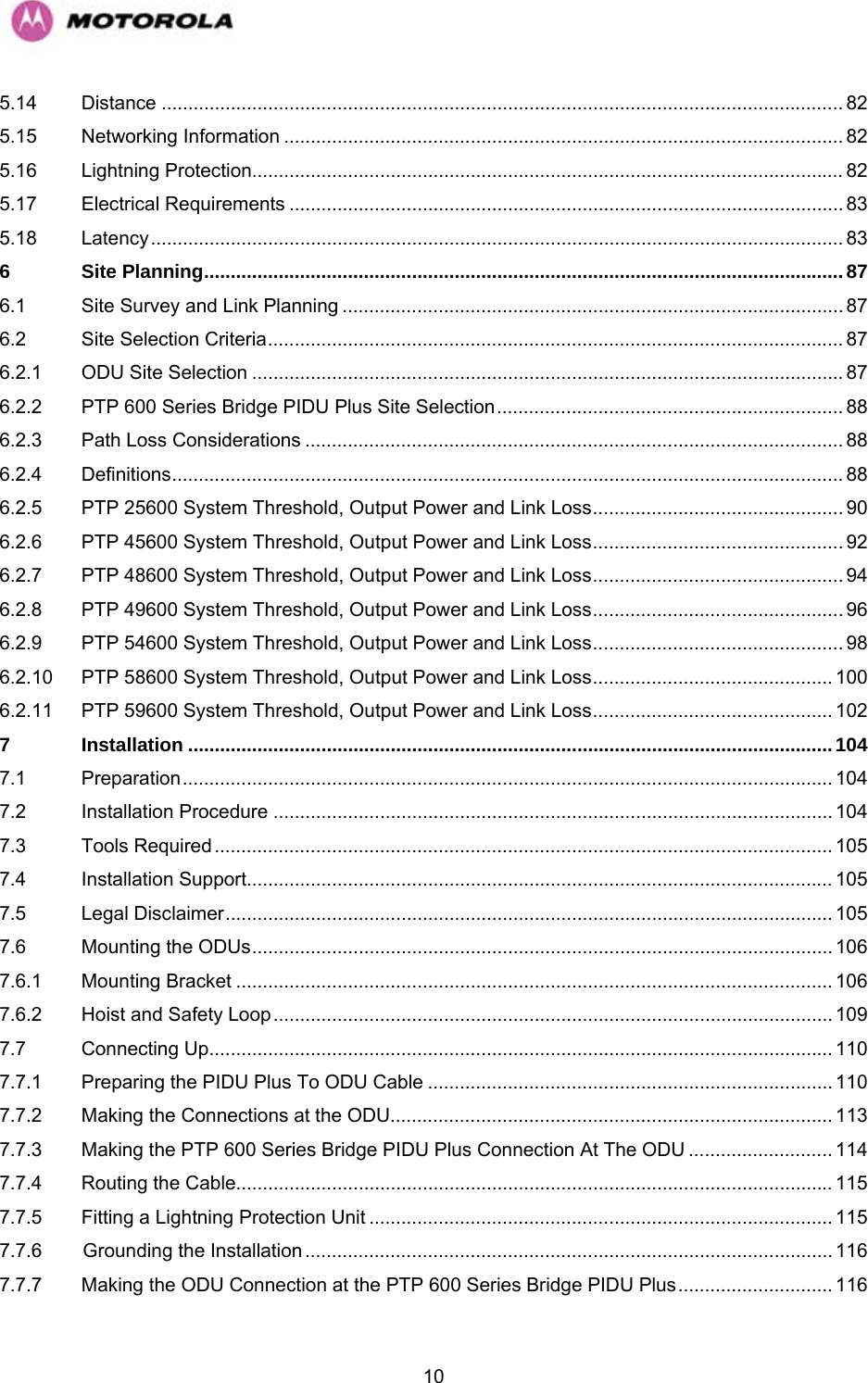
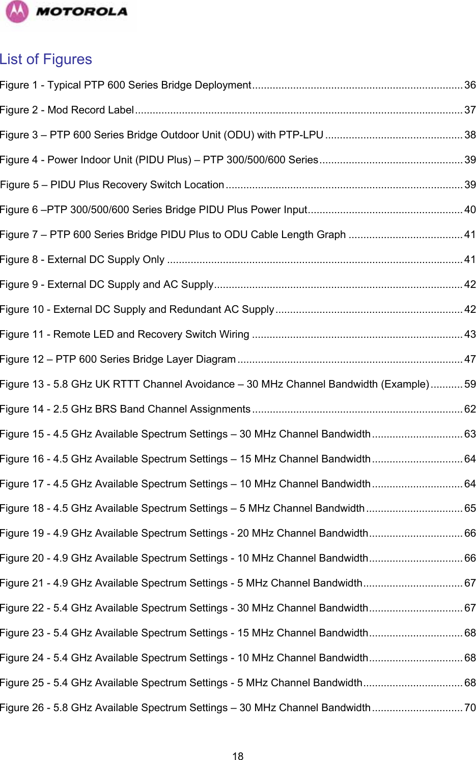
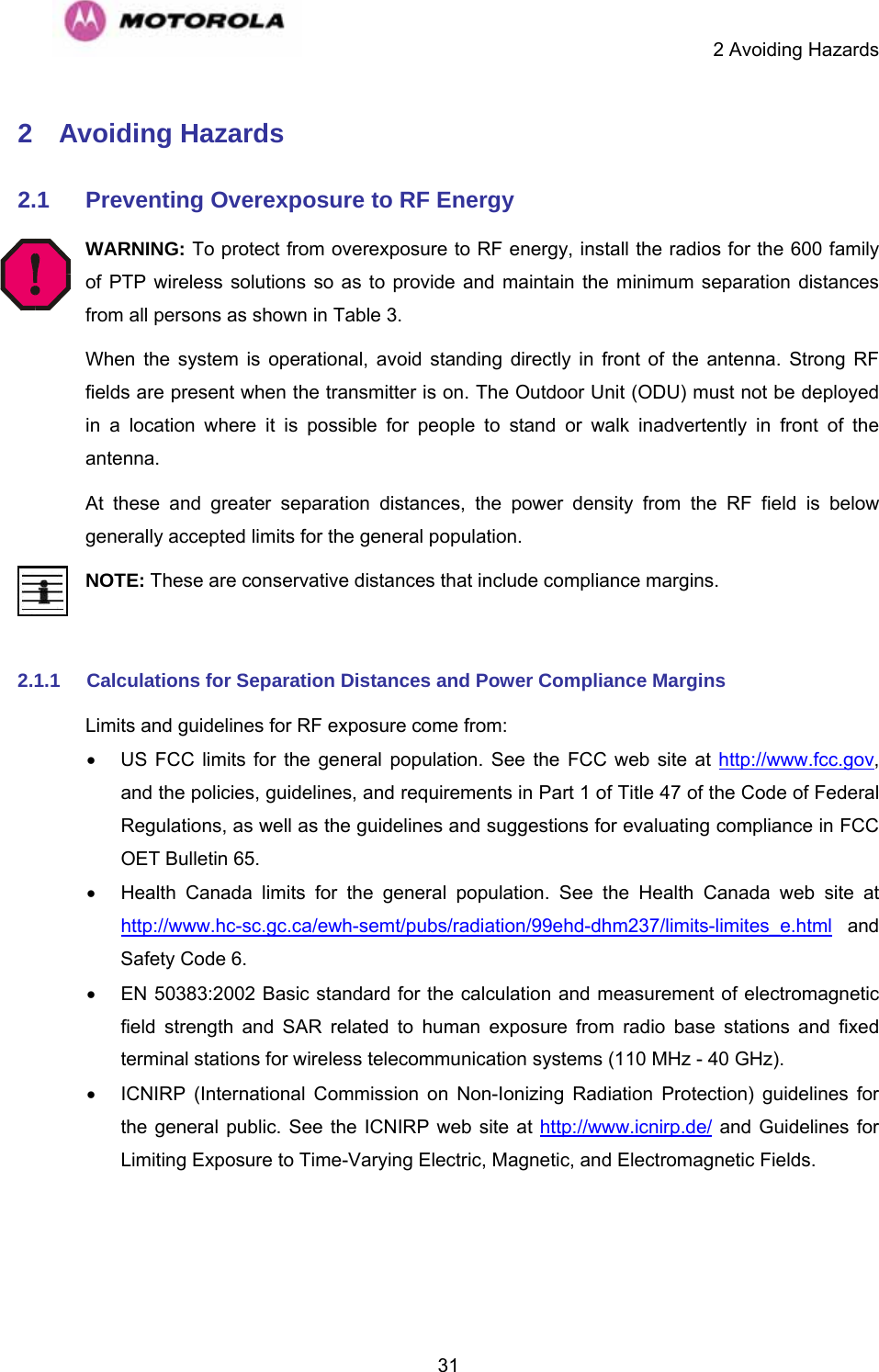
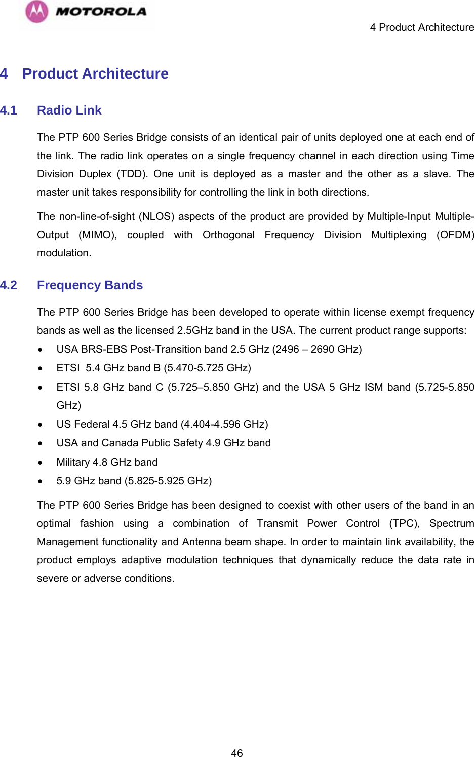
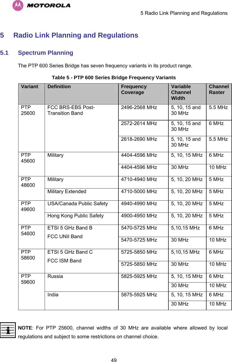
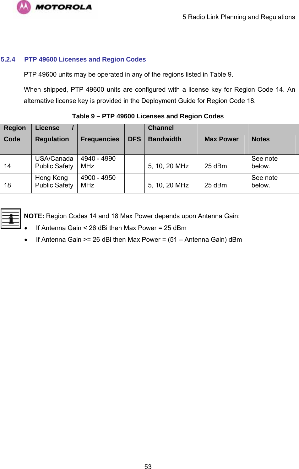
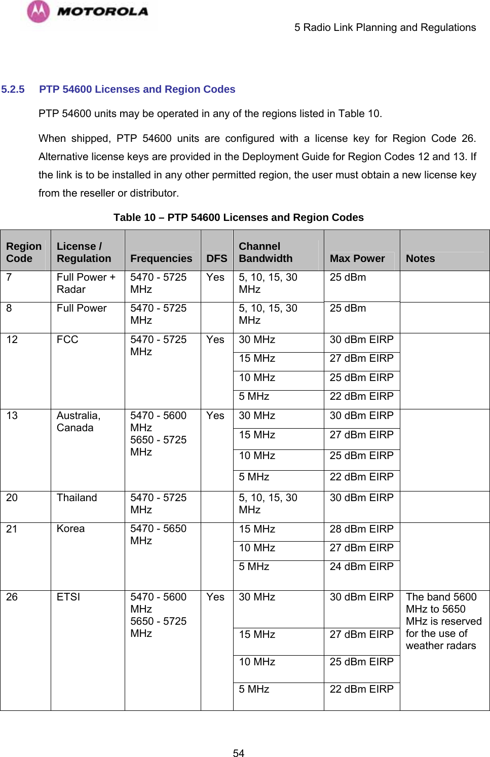
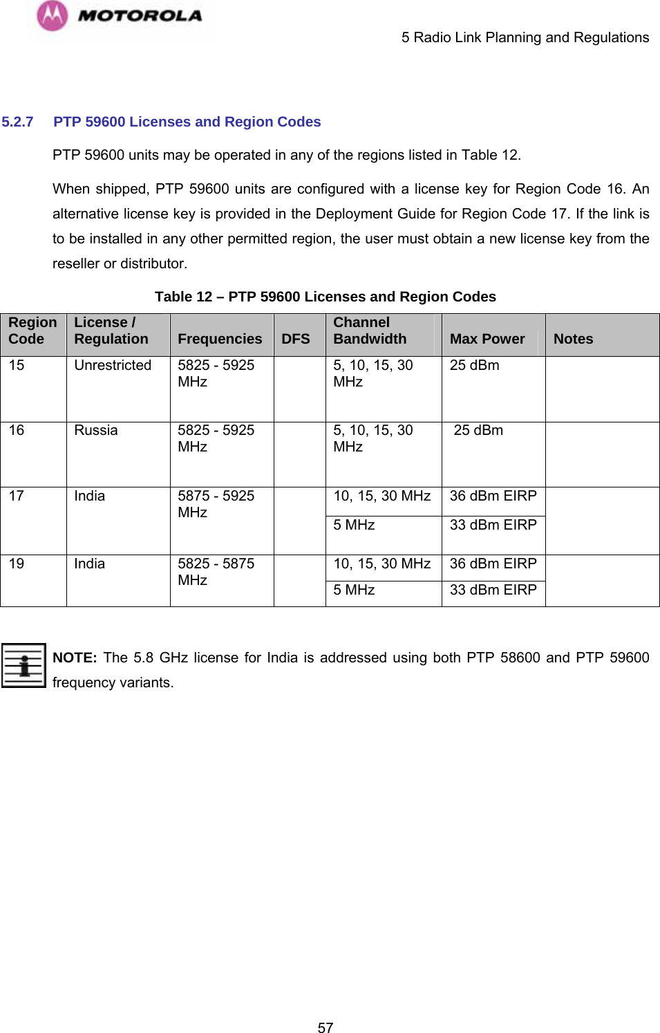
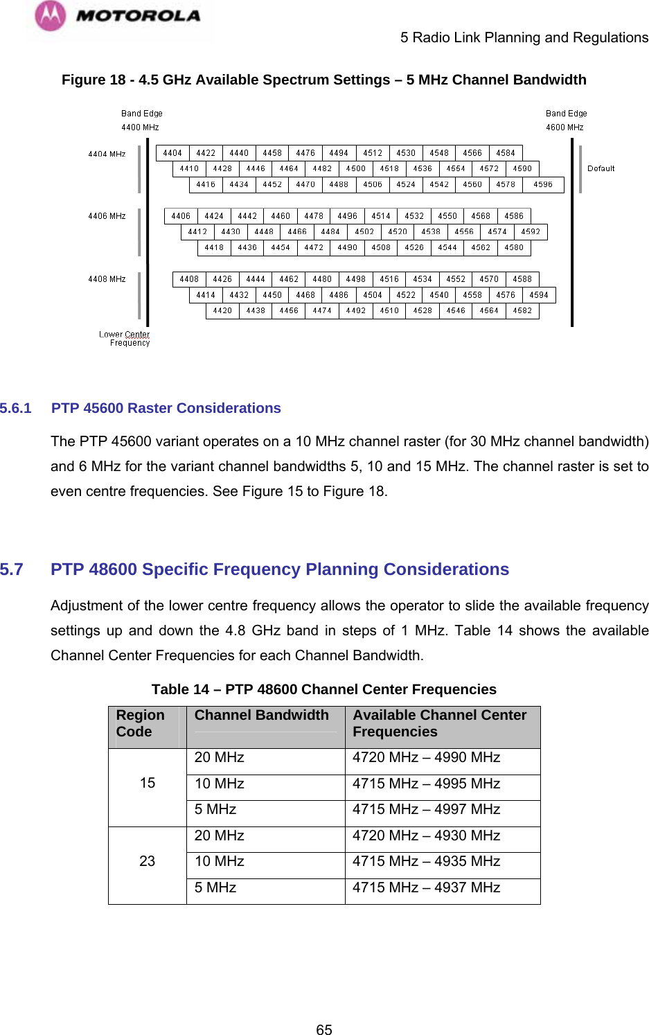
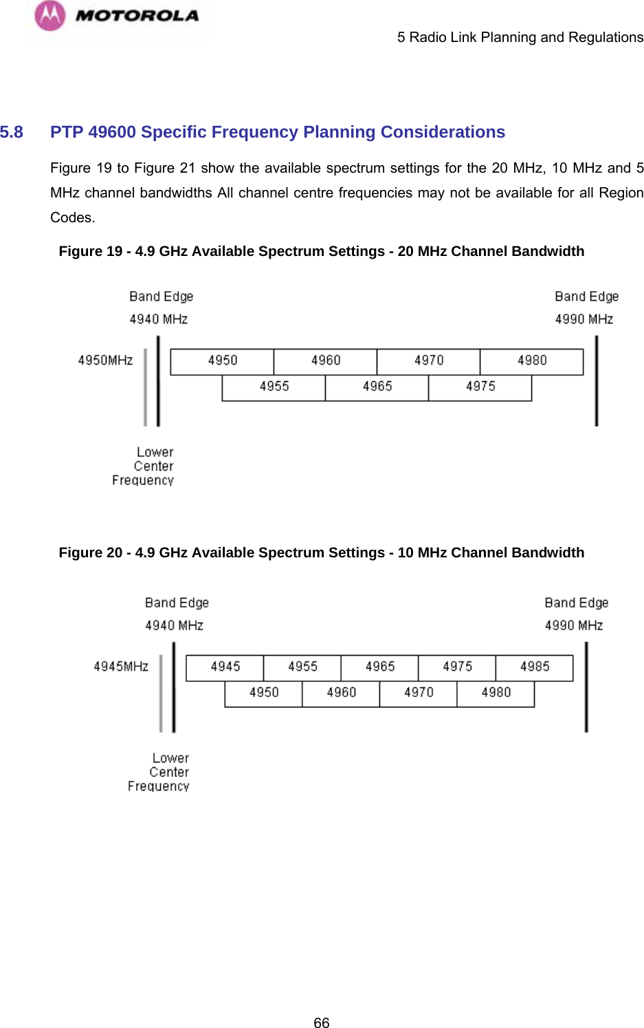
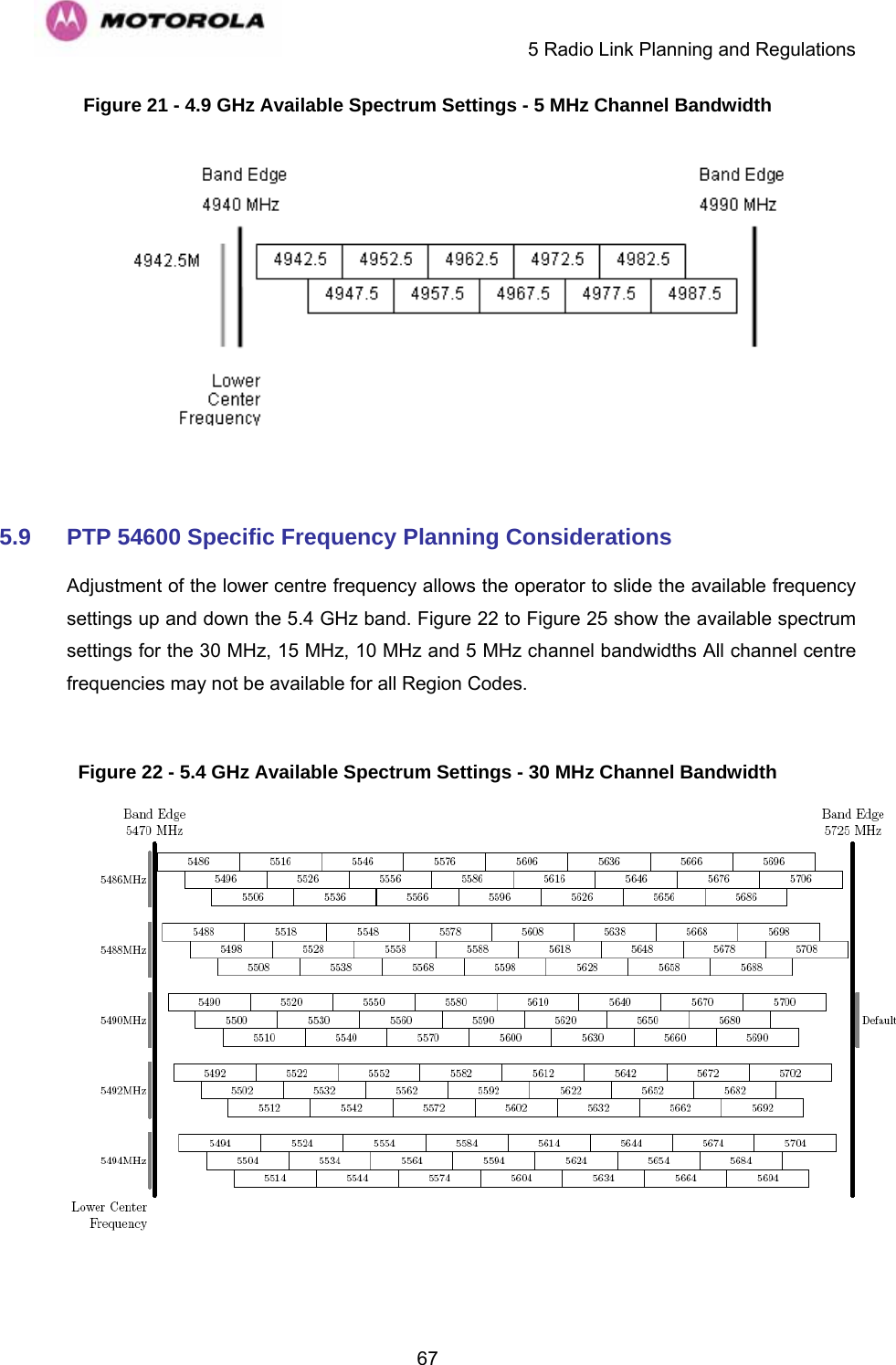
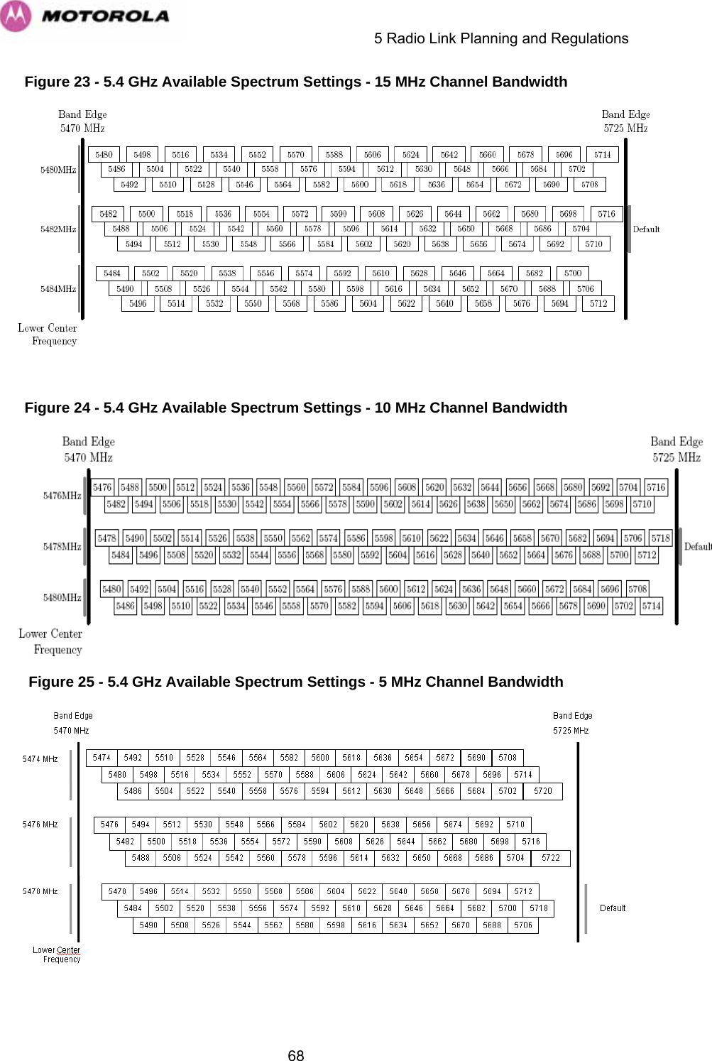
![4Regulations applicable to PTP 54600 variant Examples of Regulatory Limits at 5.4GHz FCC Operation of this product is only allowed with a License Key for Region 12. This implements Radar Detection in accordance with FCC Regulations and limits the EIRP to the regulatory limits below: EIRP ≤ Max of [(17 +10 x Log(Channel BW)) and 30] dBm. ETSI Operation of this product is only allowed with a License Key for Region 26. This implements Radar Detection, including barring of the band from 5600 MHz to 5650 MHz and limits the EIRP to the regulatory limits below: EIRP ≤ Max of [(17 +10 x Log(Channel BW)) and 30] dBm Australia, Canada Operation of this product is only allowed with a License Key for Region 13. This implements Radar Detection, including barring of the band from 5600 MHz to 5650 MHz and limits the EIRP to the regulatory limits below: EIRP ≤ Max of [(17 +10 x Log(Channel BW)) and 30] dBm Thailand Operation of this product is only allowed with a License Key for Region 20 (30 dBm or 1W EIRP) Korea Operation of this product is only allowed with a License Key for Region 21 (28 dBm EIRP (15 MHz), 27 dBm EIRP (10 MHz), 24 dBm EIRP (5 MHz)). General Notice Applicable to Europe This equipment complies with the essential requirements for the EU R&E Directive 1999/5/EC. NOTE: In regions other than EU/USA, specific local regulations may apply. It is the responsibility of the installer/user to check that the equipment as deployed meets local regulatory requirements.](https://usermanual.wiki/Cambium-Networks/25601/User-Guide-1067252-Page-6.png)
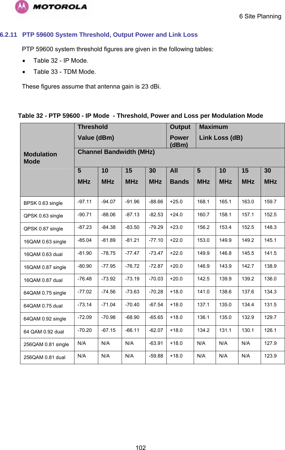
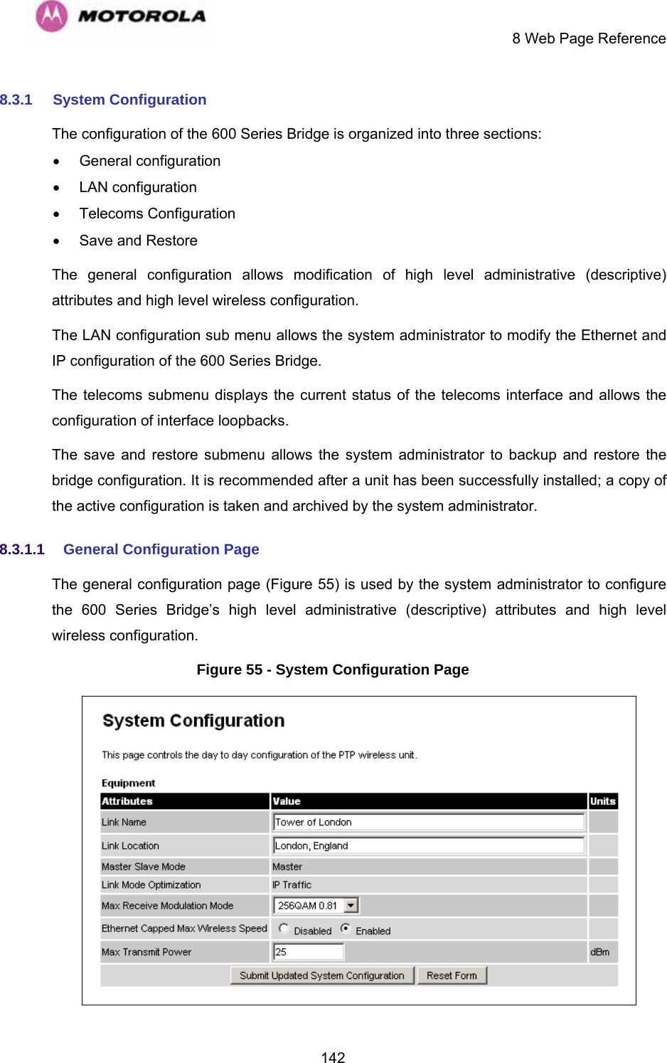
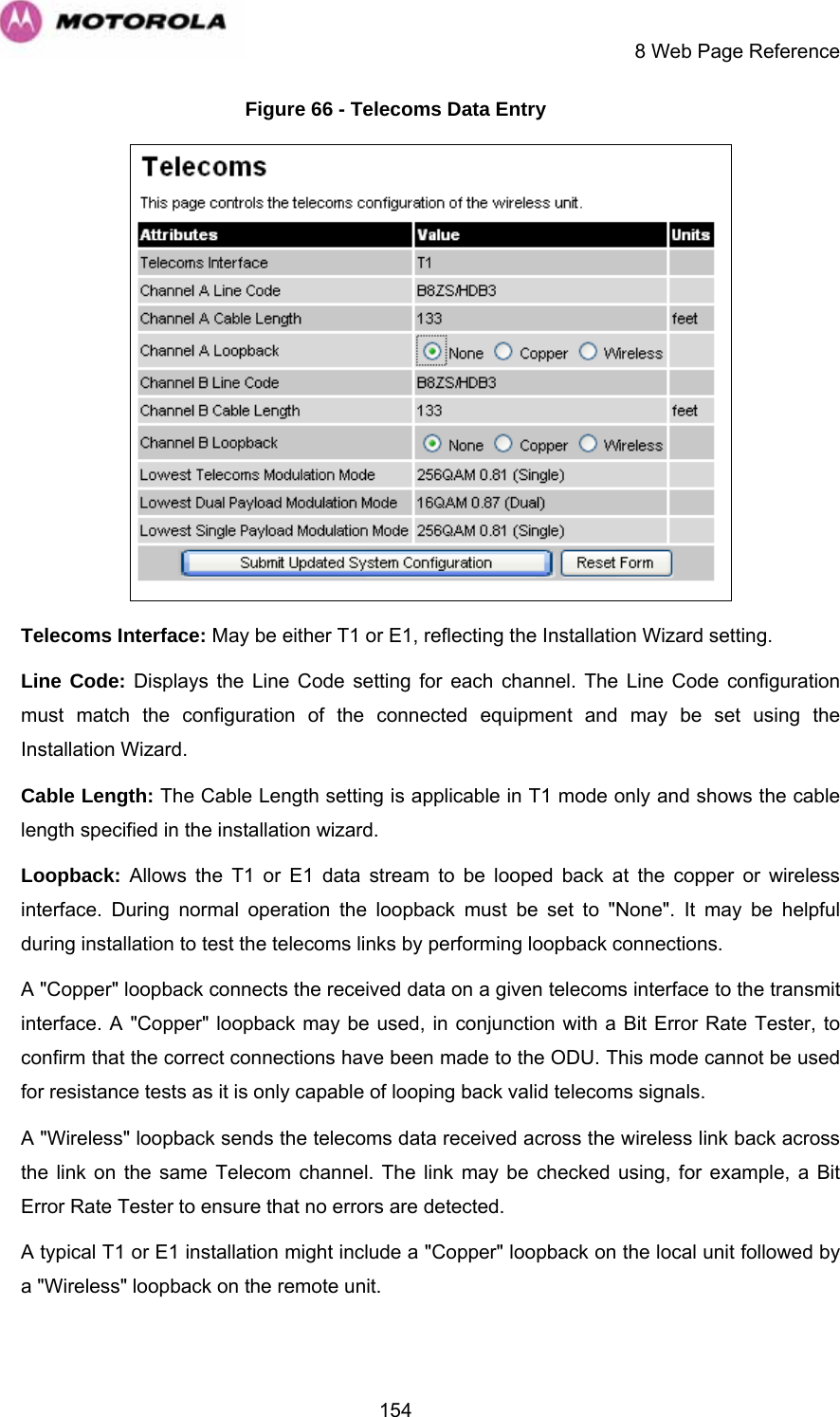
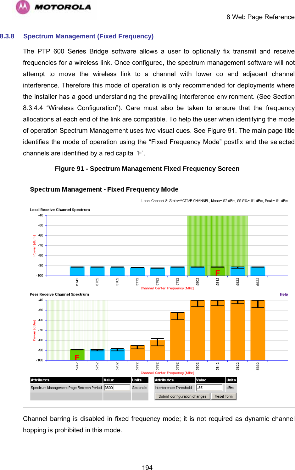
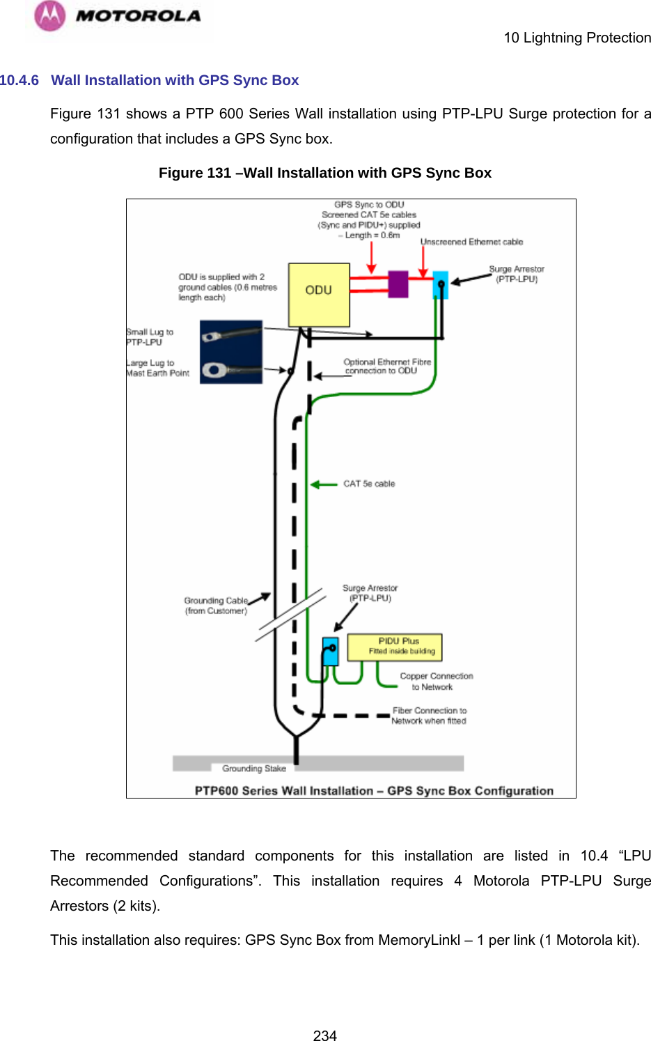
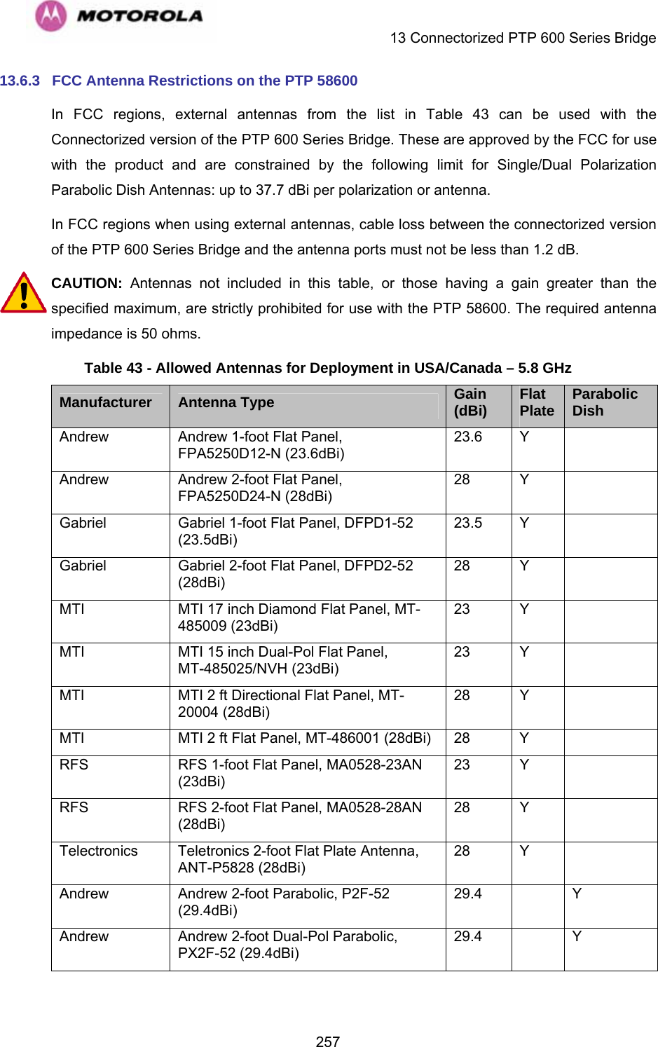
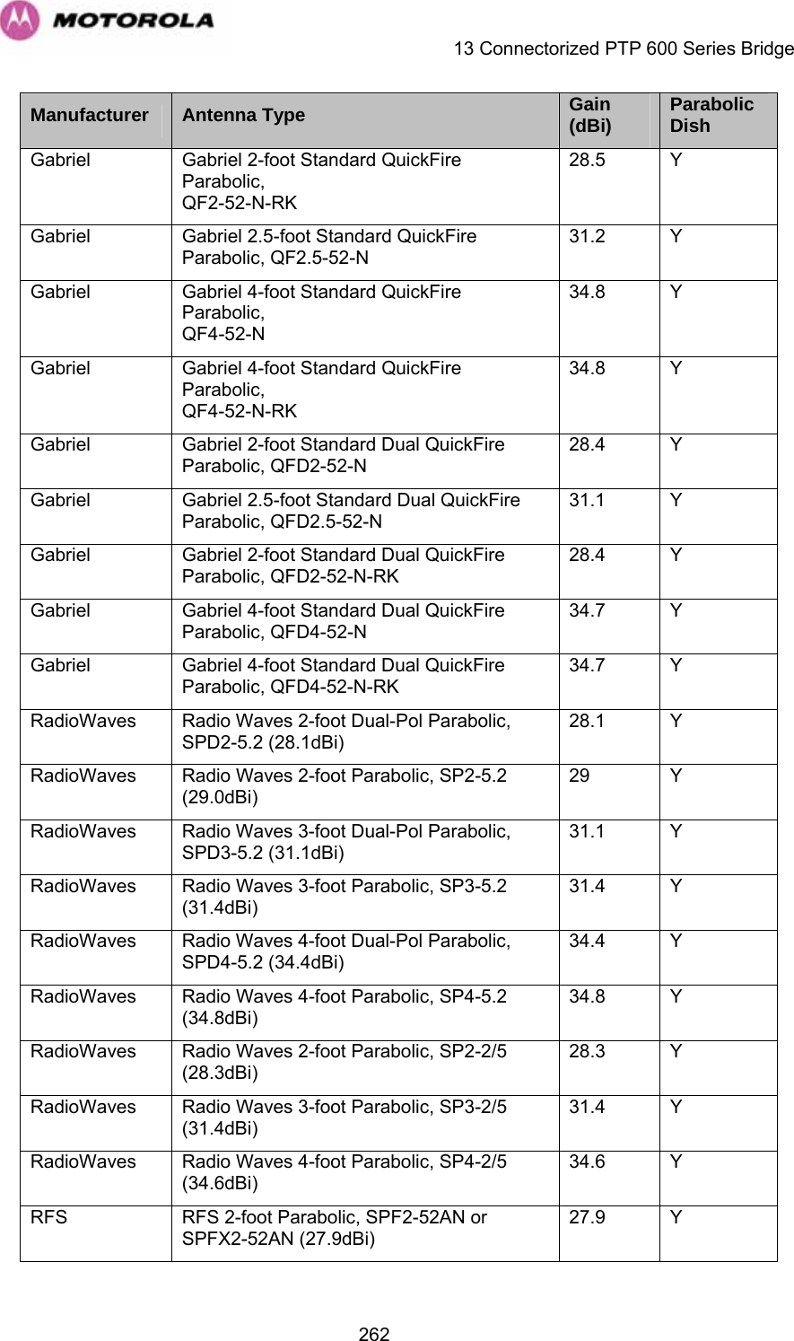
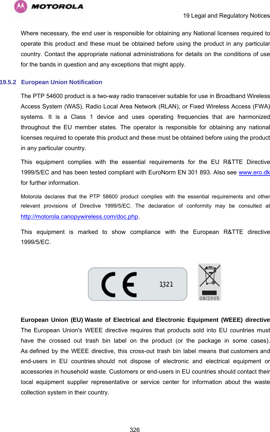
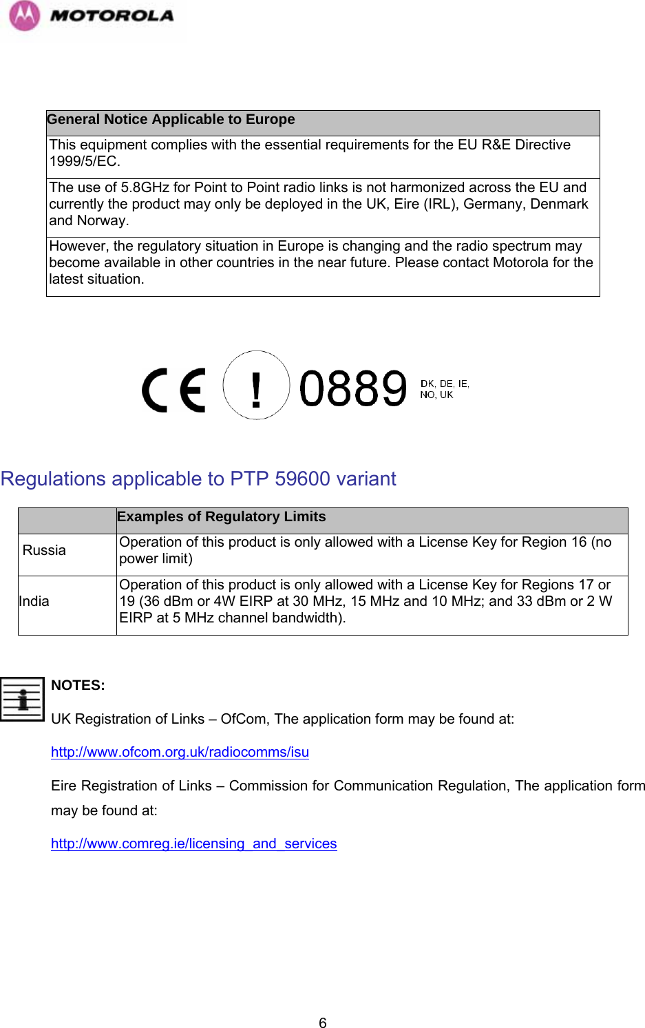
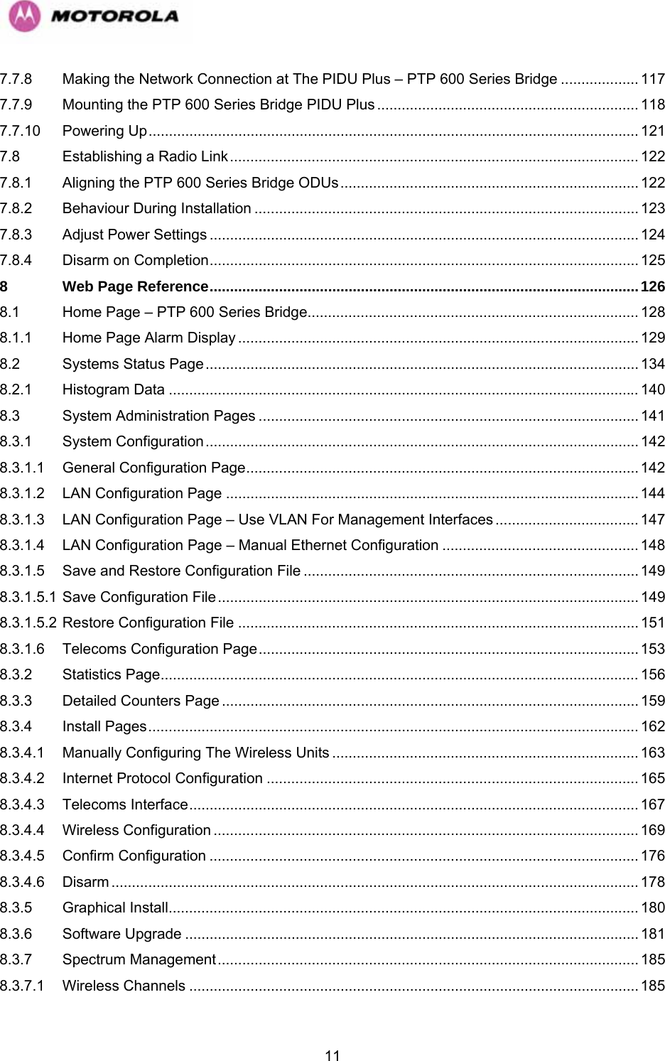
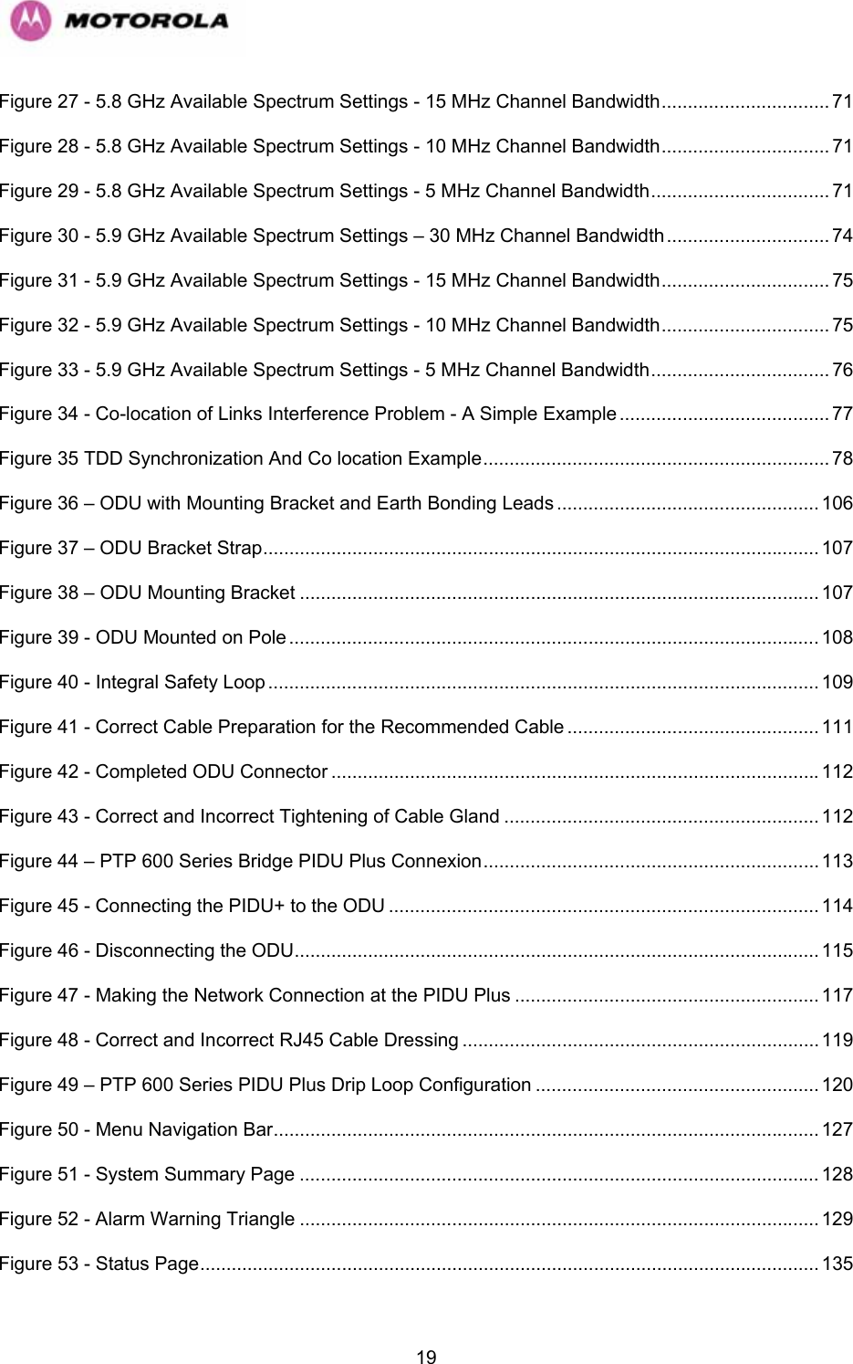
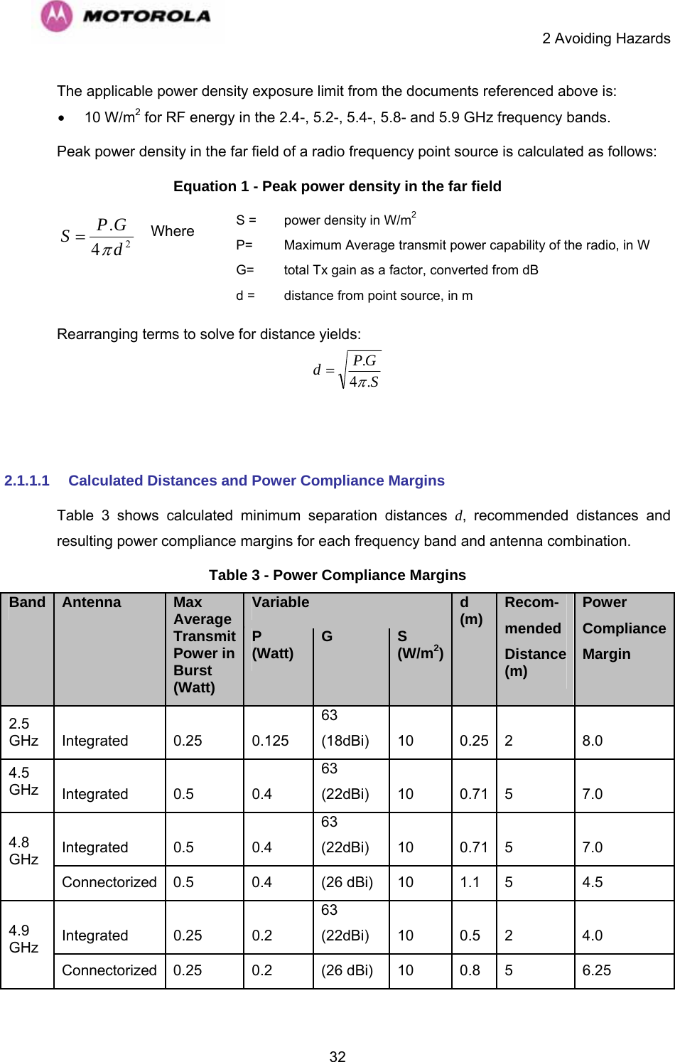
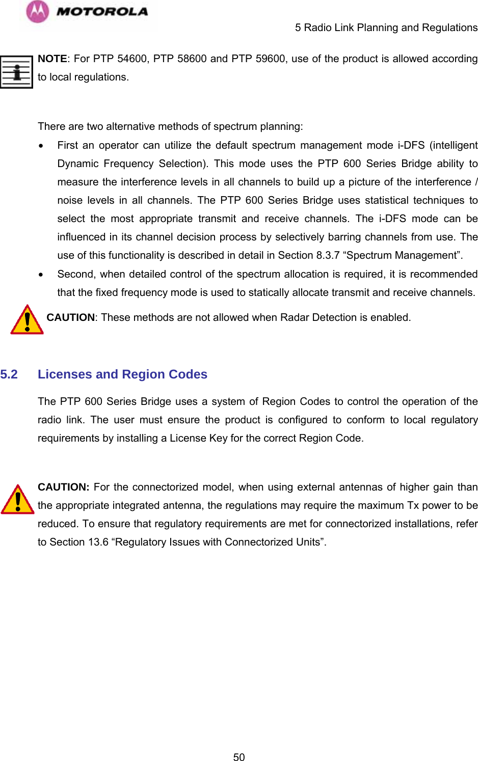
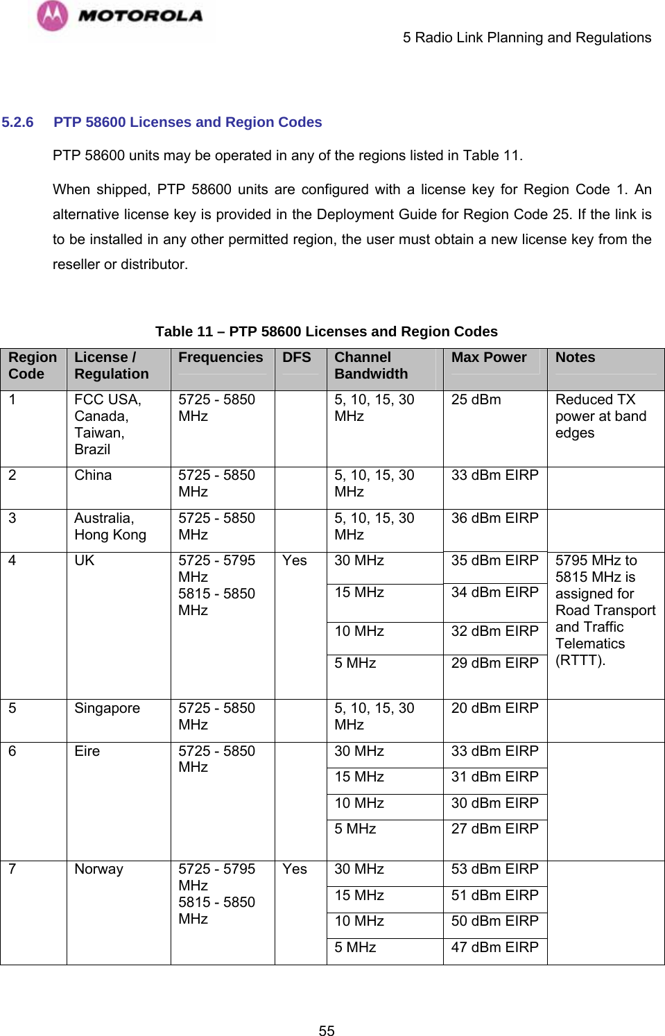
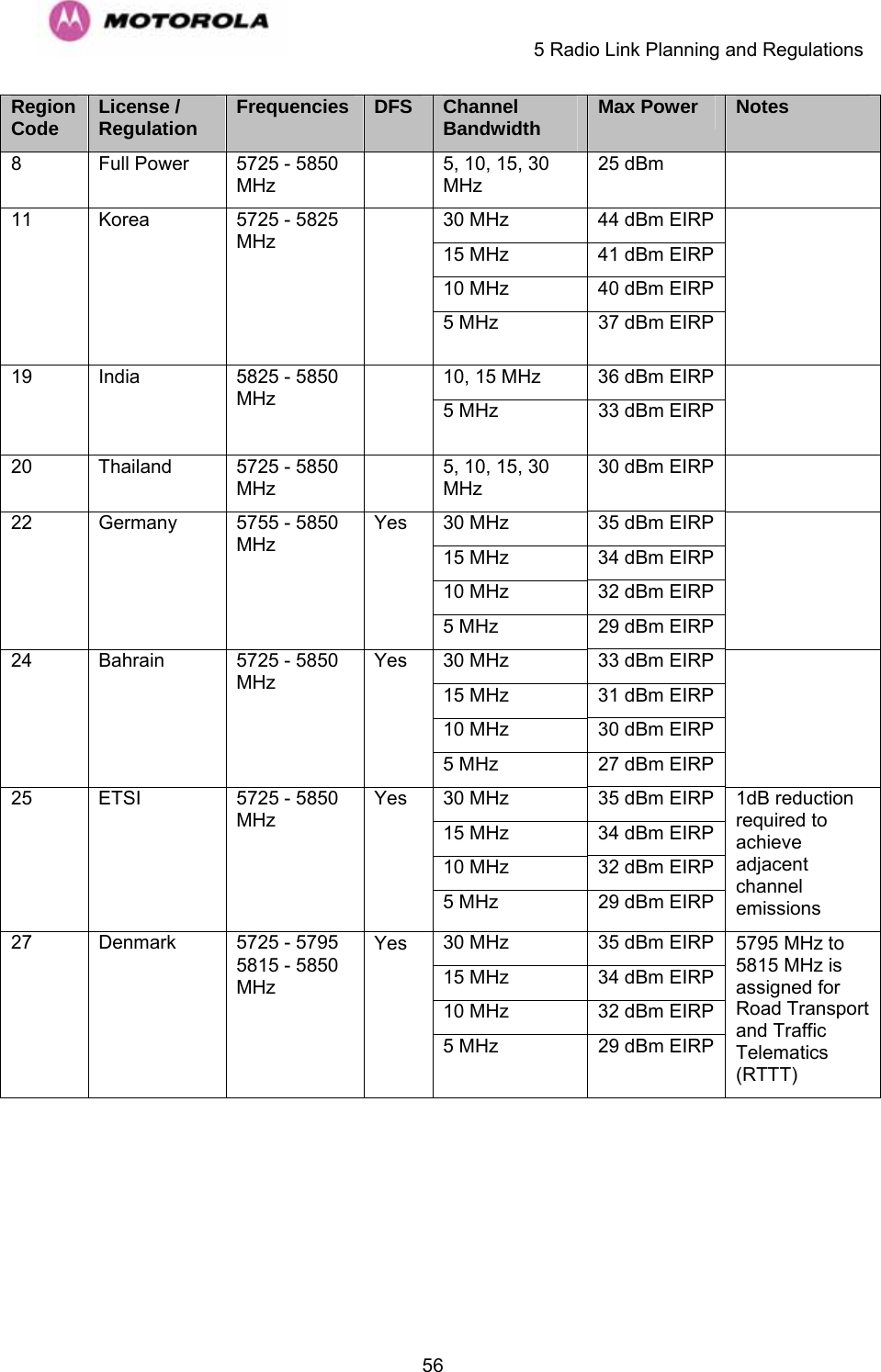
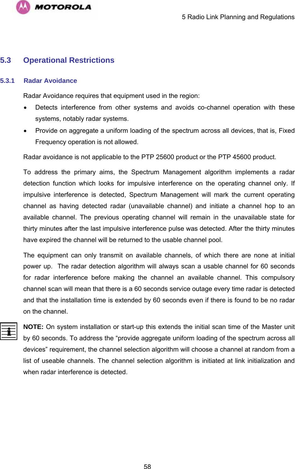
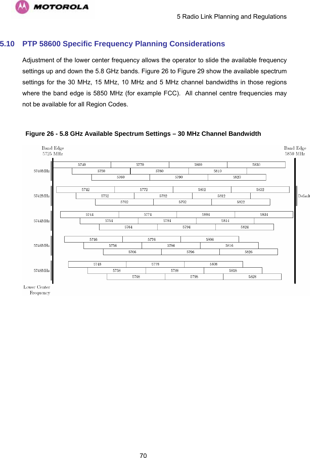
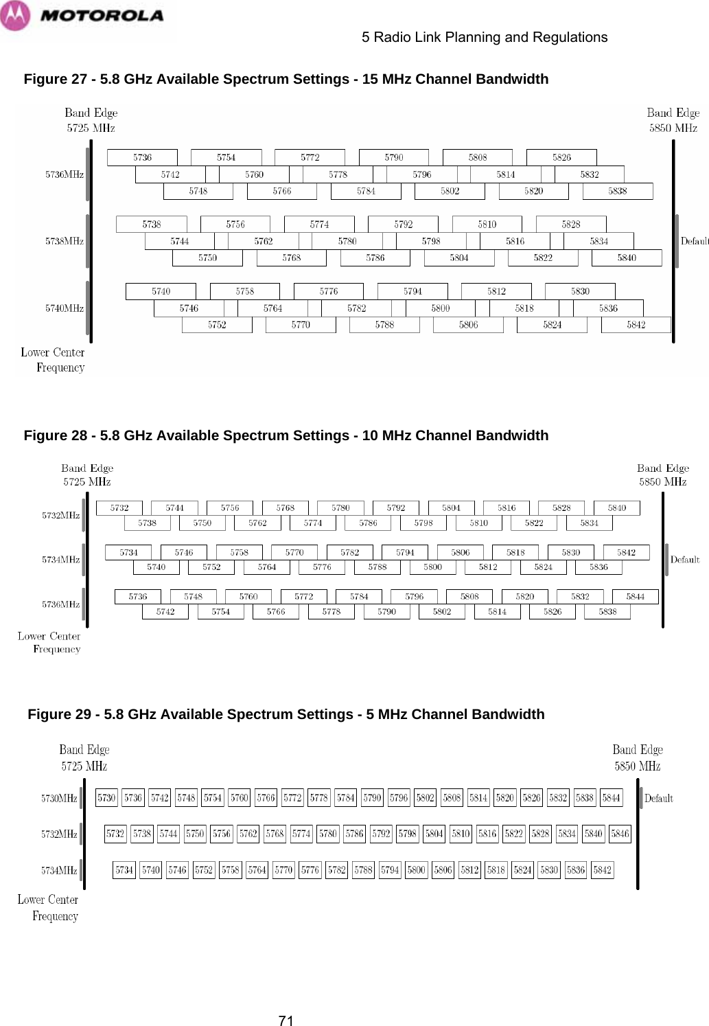
![5Regulations applicable to PTP 58600 variant Examples of Regulatory Limits USA/ Canada/ Taiwan/ Brazil Equipment can be operated in any mode, best results will be obtained using Region 1 settings. There are some limitations on the use of antennas above 4ft diameter plus a band edge power reduction. China Operation of this product is only allowed with a License Key for Region 2 (33 dBm or 2W EIRP). Australia Operation of this product is only allowed with a License Key for Region 3 (36 dBm or 4W EIRP). Hong Kong Operation of this product is only allowed with a License Key for Region 3 (36 dBm or 4W EIRP). UK Operation of this product is allowed with a License Key for Region 4 . This implements Radar Detection with barring of the band from 5795 MHz to 5815 MHz and above 5850 MHz. It limits the EIRP to the Regulatory Limits below: EIRP ≤ Max of [(23 +10 x Log(Channel BW)) and 36] dBm Singapore Operation of this product is only allowed with a License Key for Region 5 (20 dBm or 100mW EIRP). Eire Operation of this product is only allowed with a License Key for Region 6 (33 dBm or 2W EIRP). The lower power limits are lower in narrower bandwidths. Korea Operation of this product is only allowed with a License Key for Region 11 (43 dBm or 20W EIRP). India Operation of this product is only allowed with a License Key for Region 19 (36 dBm or 4W EIRP at 15 MHz and 10 MHz and 33 dBm or 2 W EIRP at 5 MHz channel bandwidth). Thailand Operation of this product is only allowed with a License Key for Region 20 (30 dBm or 1W EIRP). Germany Operation of this product is only allowed with a License Key for Region 22. This limits the band of operation to 5755 MHz to 5850 MHz and limits the EIRP to the Regulatory Limits below: EIRP ≤ Max of [(23 +10 x Log(Channel BW)) and 36] dBm Bahrain Operation of this product is allowed with a License Key for Region 24 . This limits the EIRP to the Regulatory Limits below: EIRP ≤ Max of [(20 +10 x Log(Channel BW)) and 33] dBm Norway Under Norway Regulations, operation of this product is only allowed with a License Key for Region 7. This implements Radar Detection and limits the EIRP to the Regulatory Limits below: EIRP ≤ Max of [(40 +10 x Log(Channel BW)) and 53] dBm Spectral density at border between Norway and neighboring countries shall not exceed -122,5 dBW/m2 measured with a reference bandwidth of 1 MHz.](https://usermanual.wiki/Cambium-Networks/25601/User-Guide-1067252-Page-7.png)

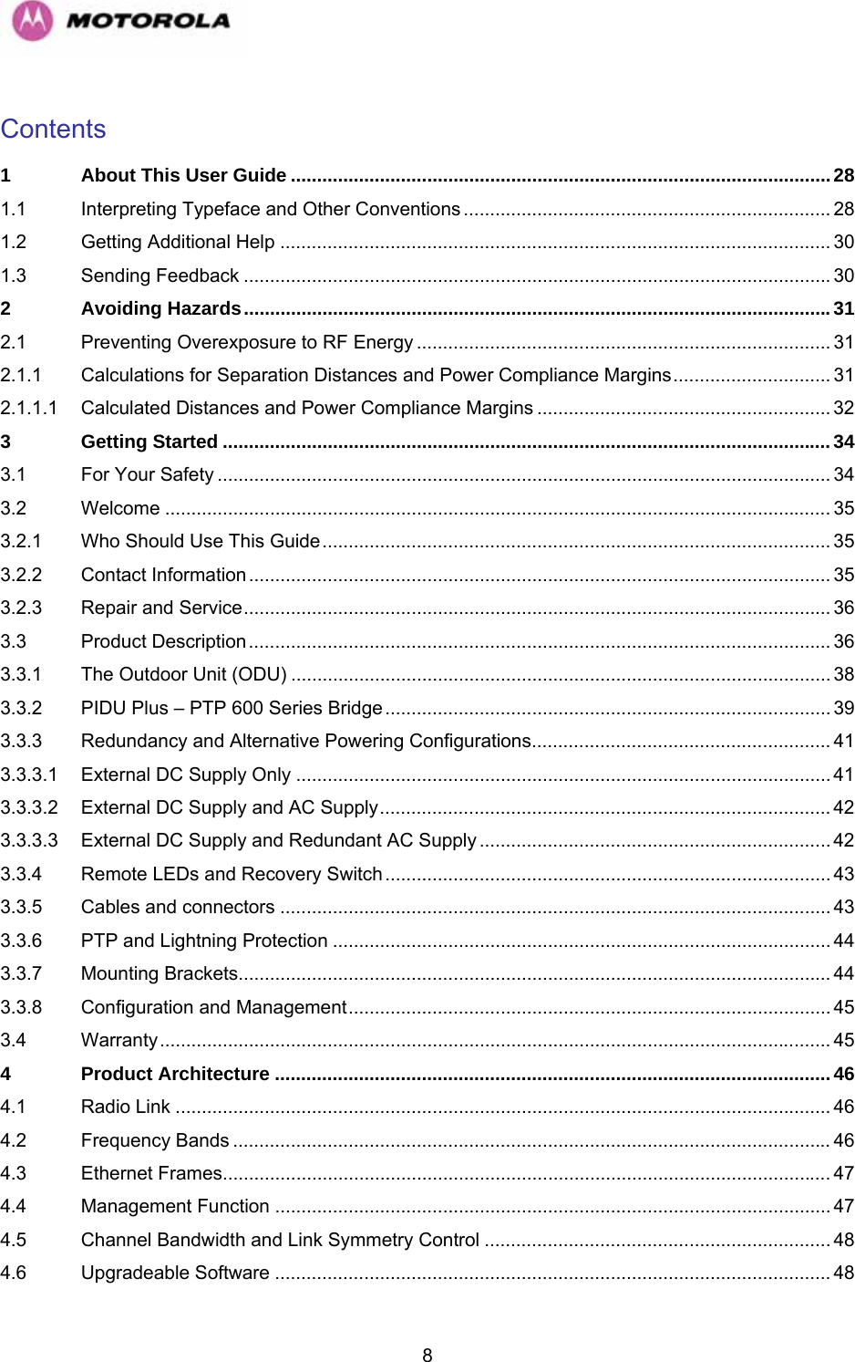
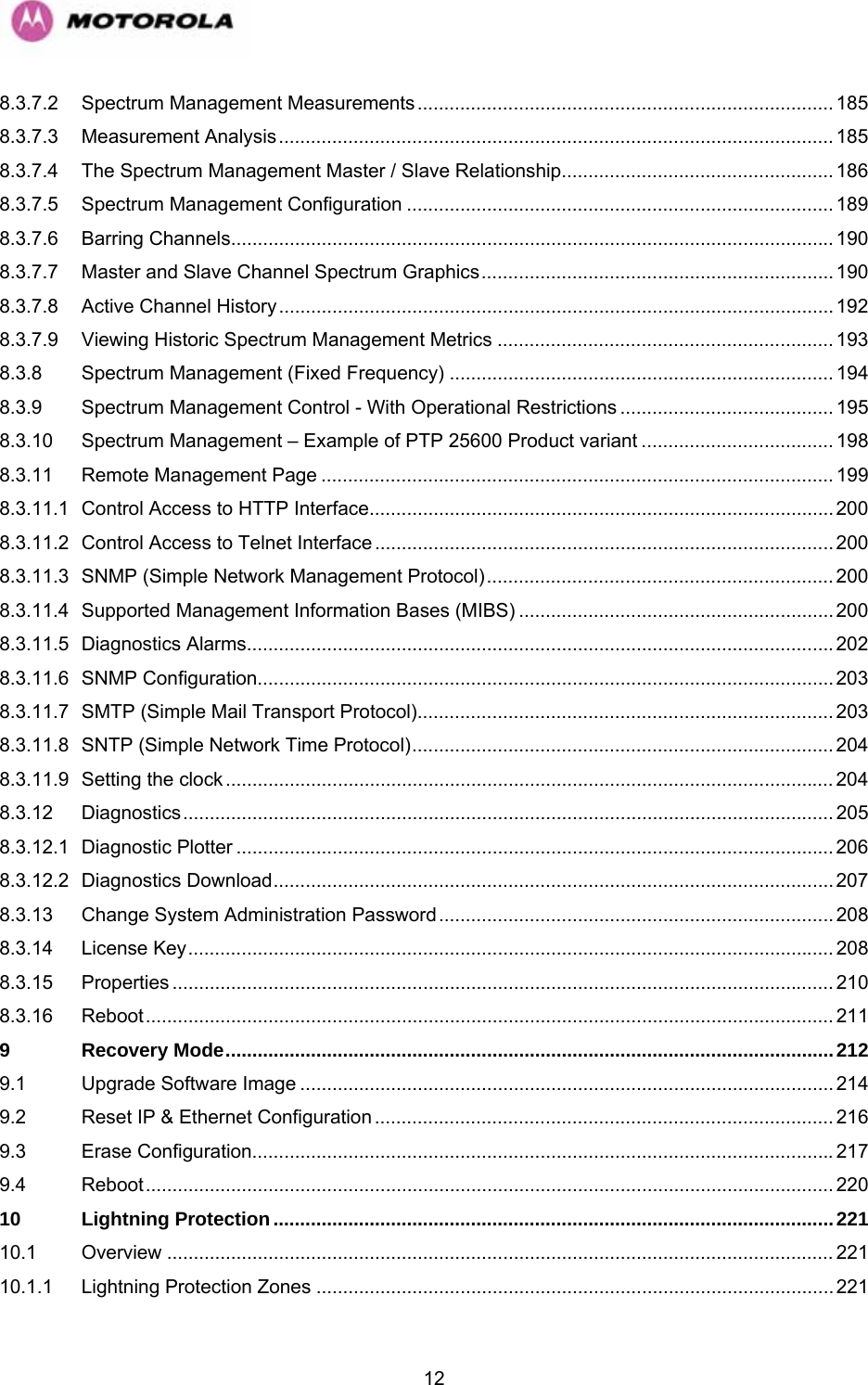
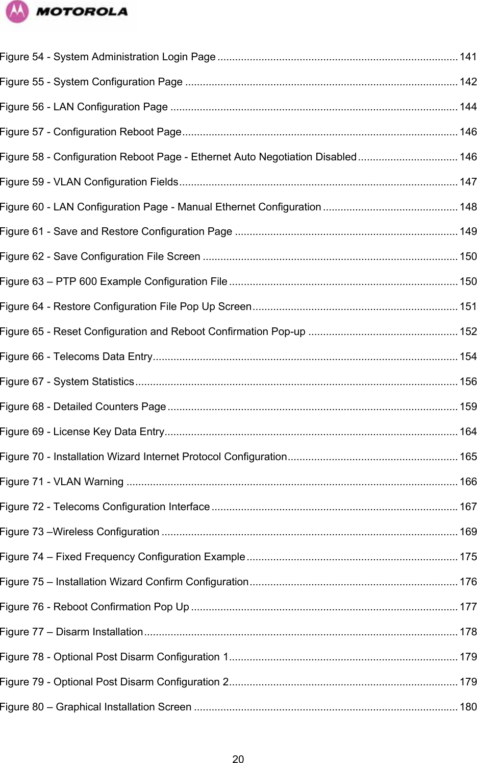

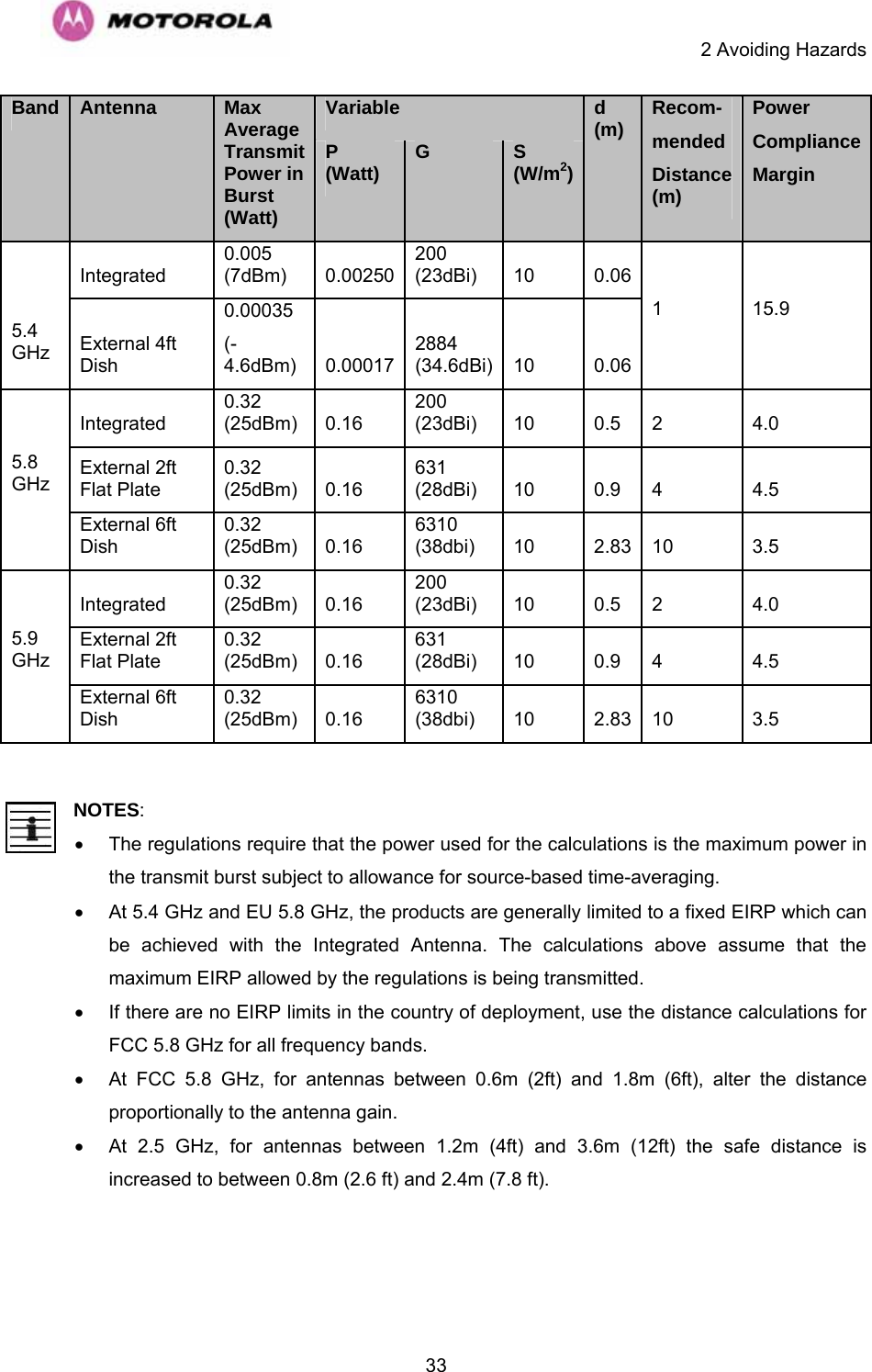

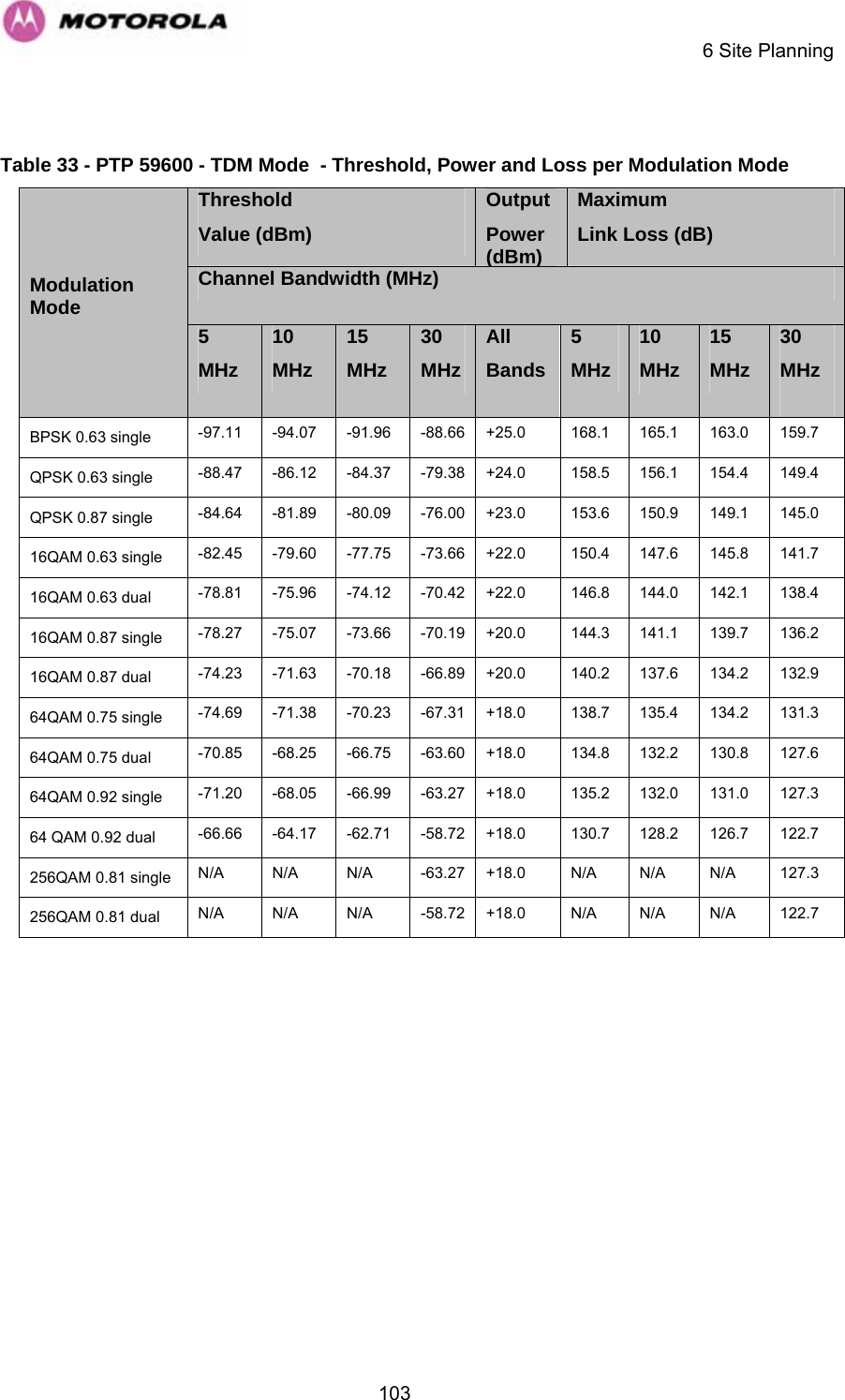
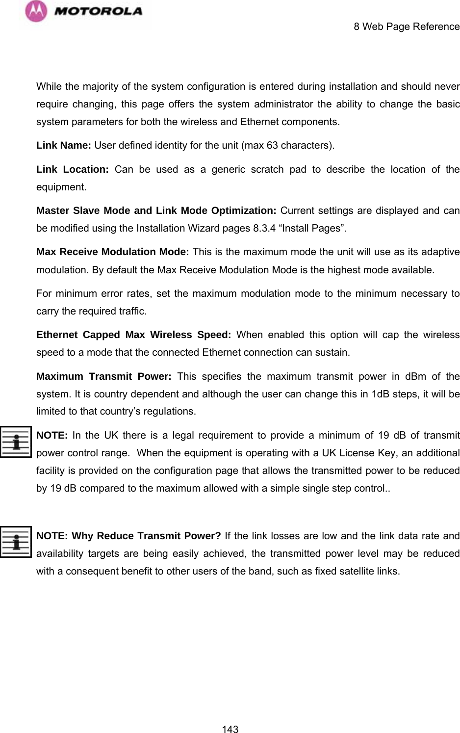
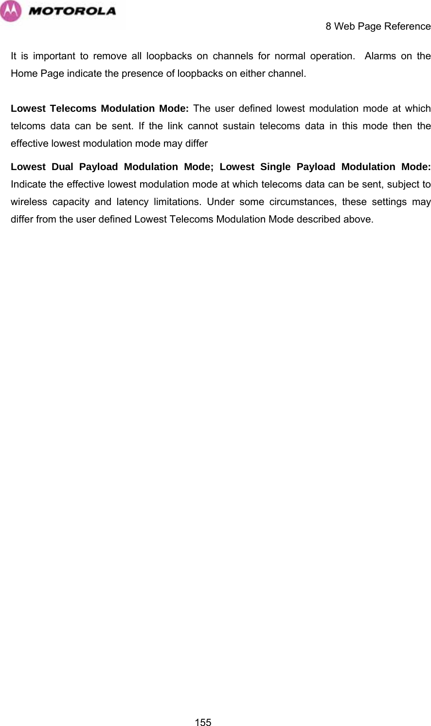
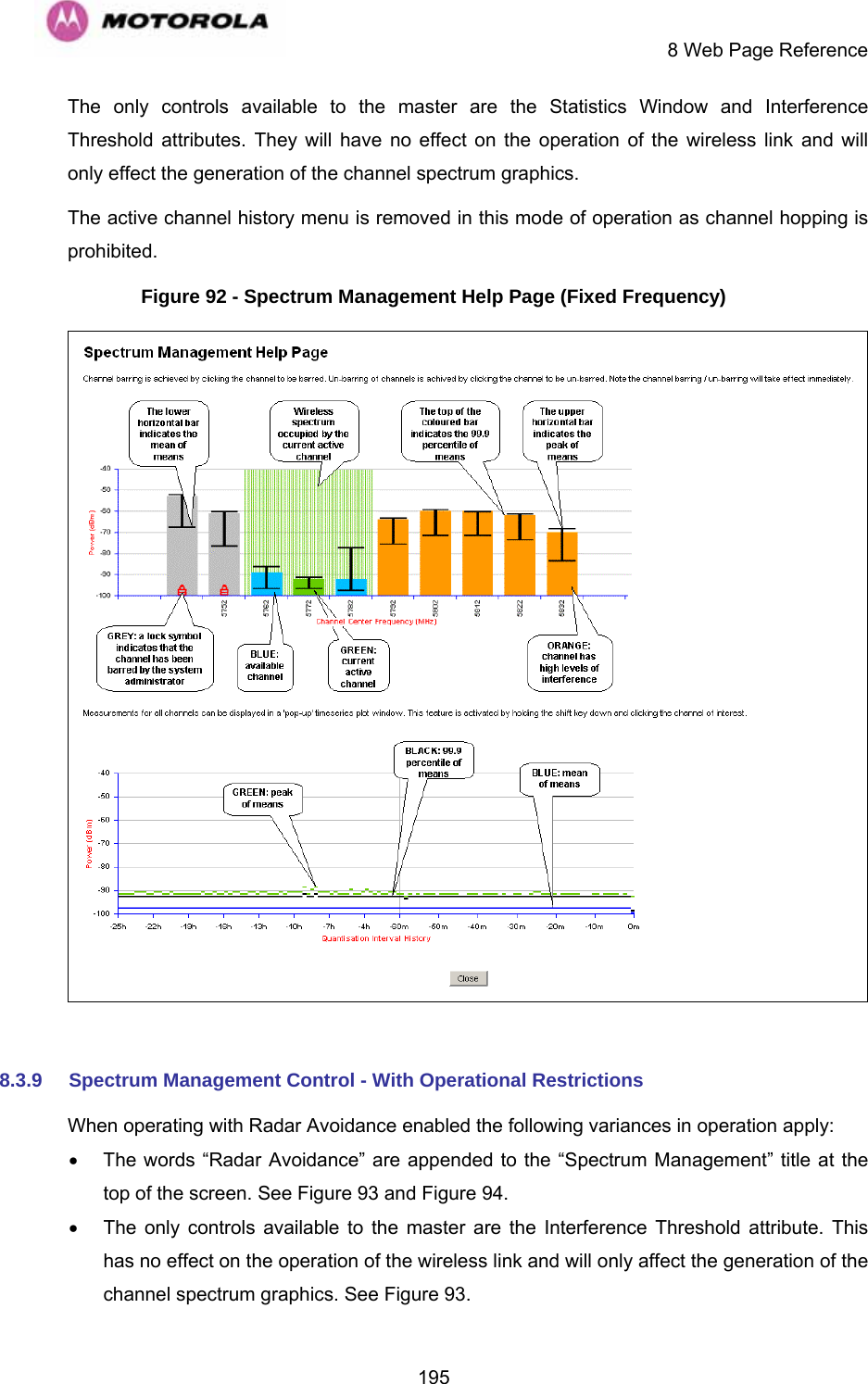
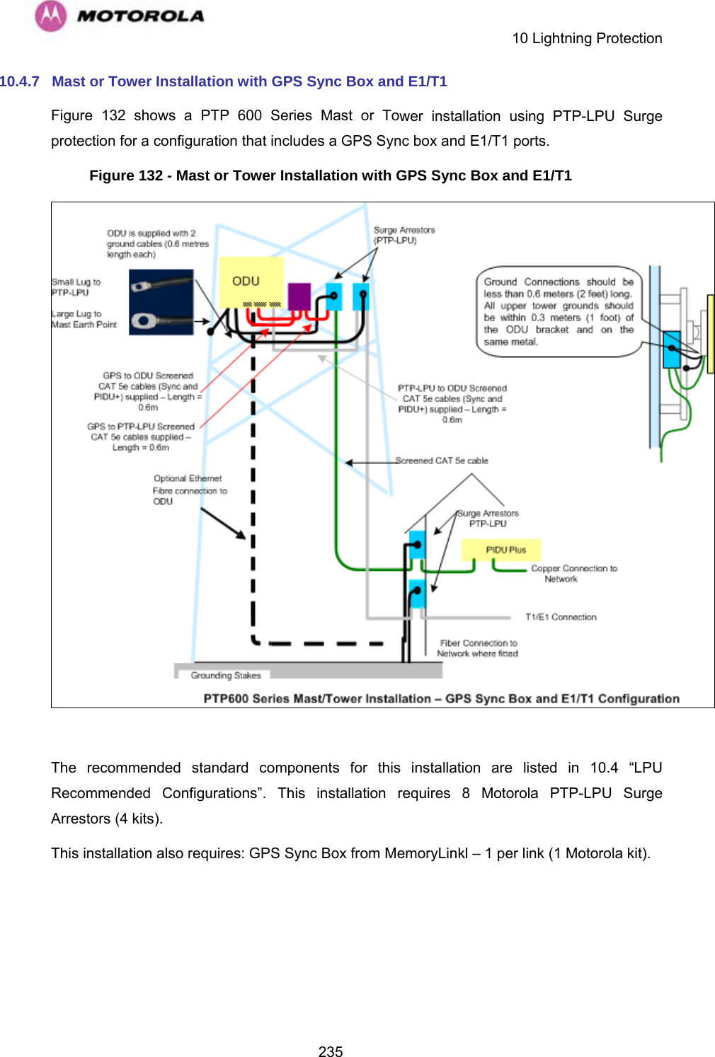
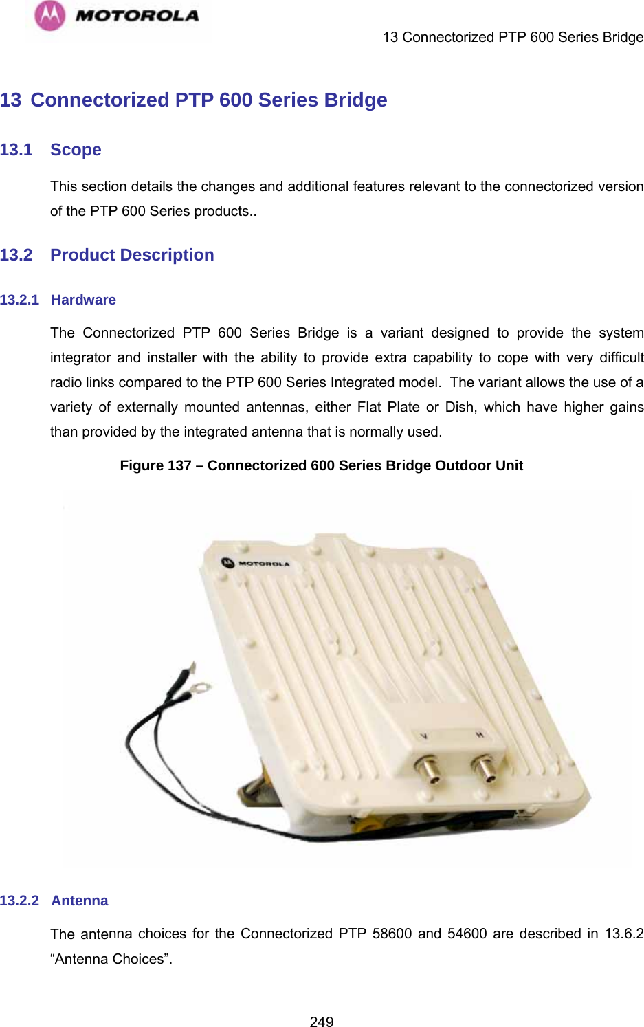
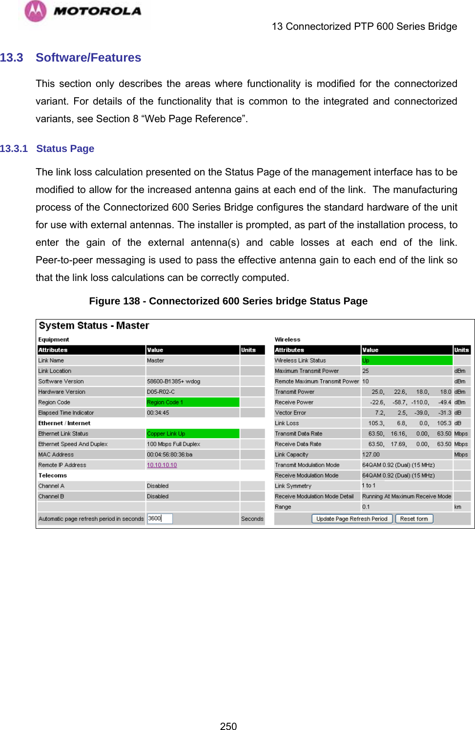
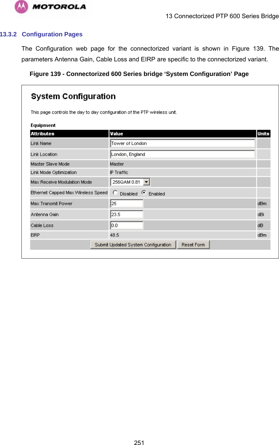
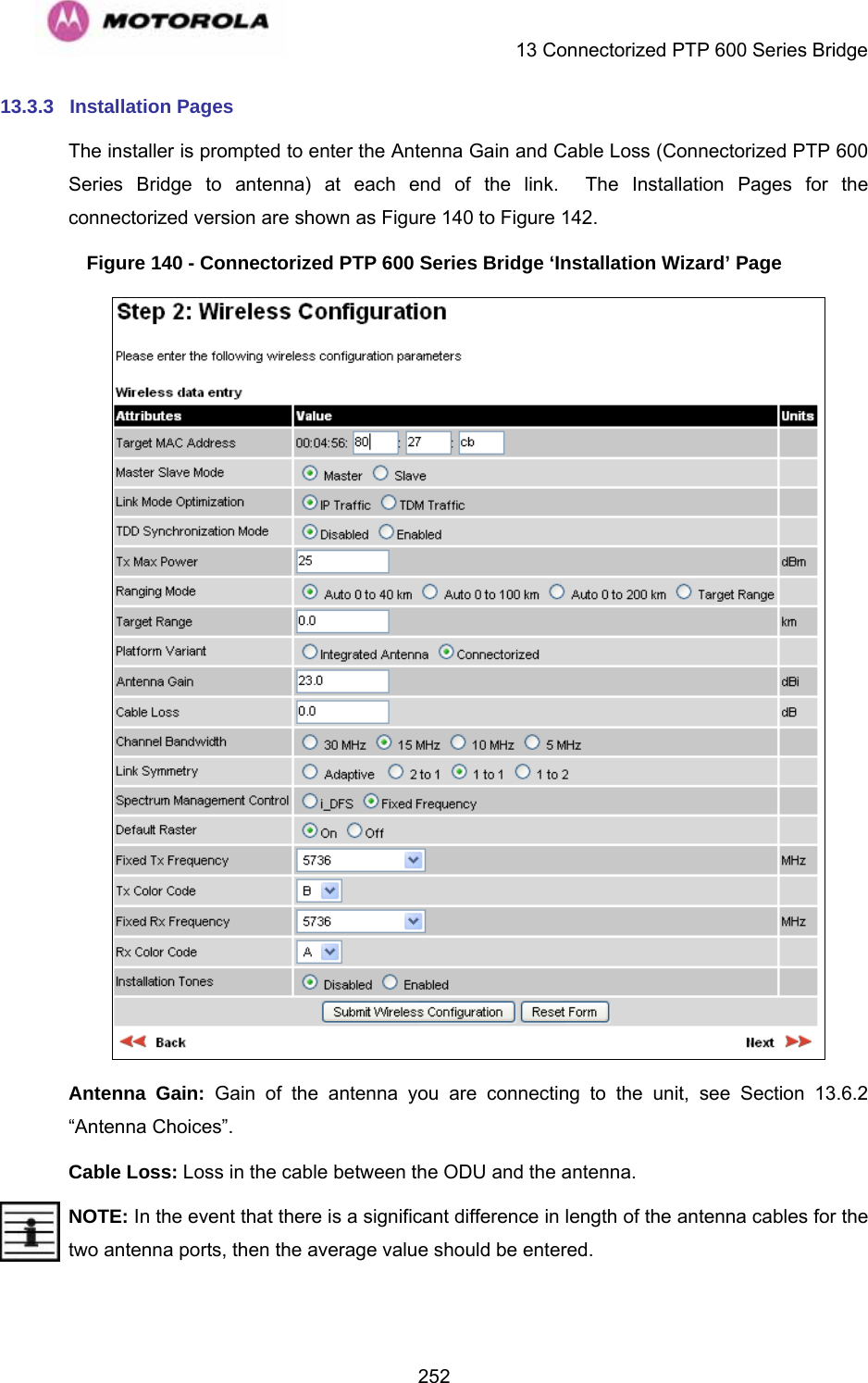
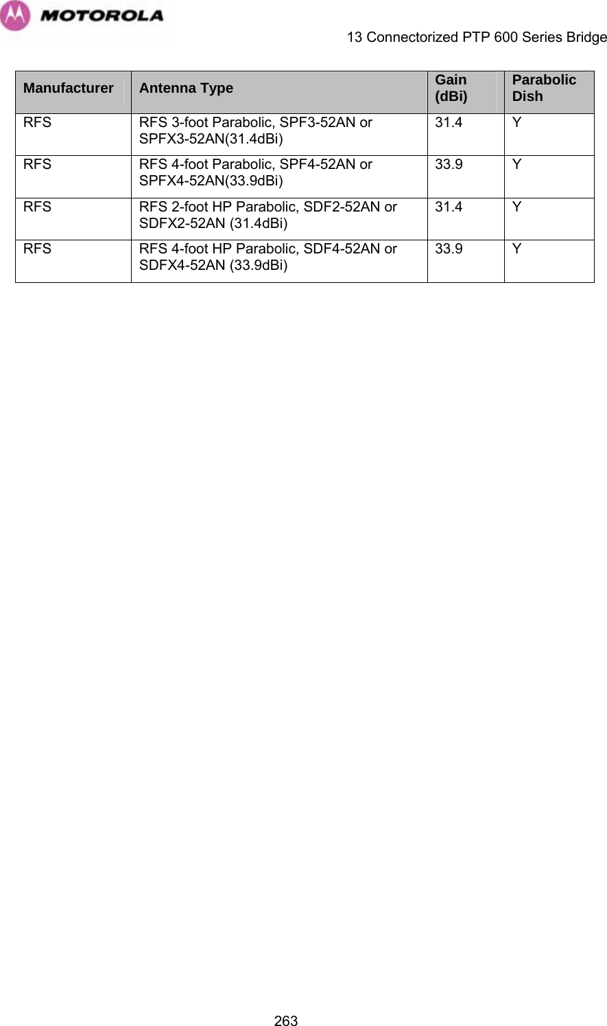
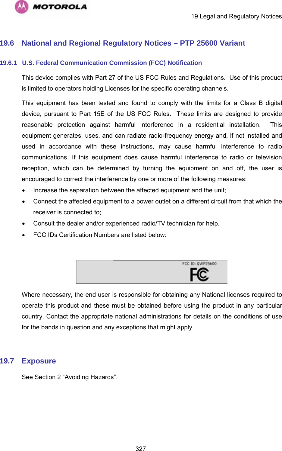
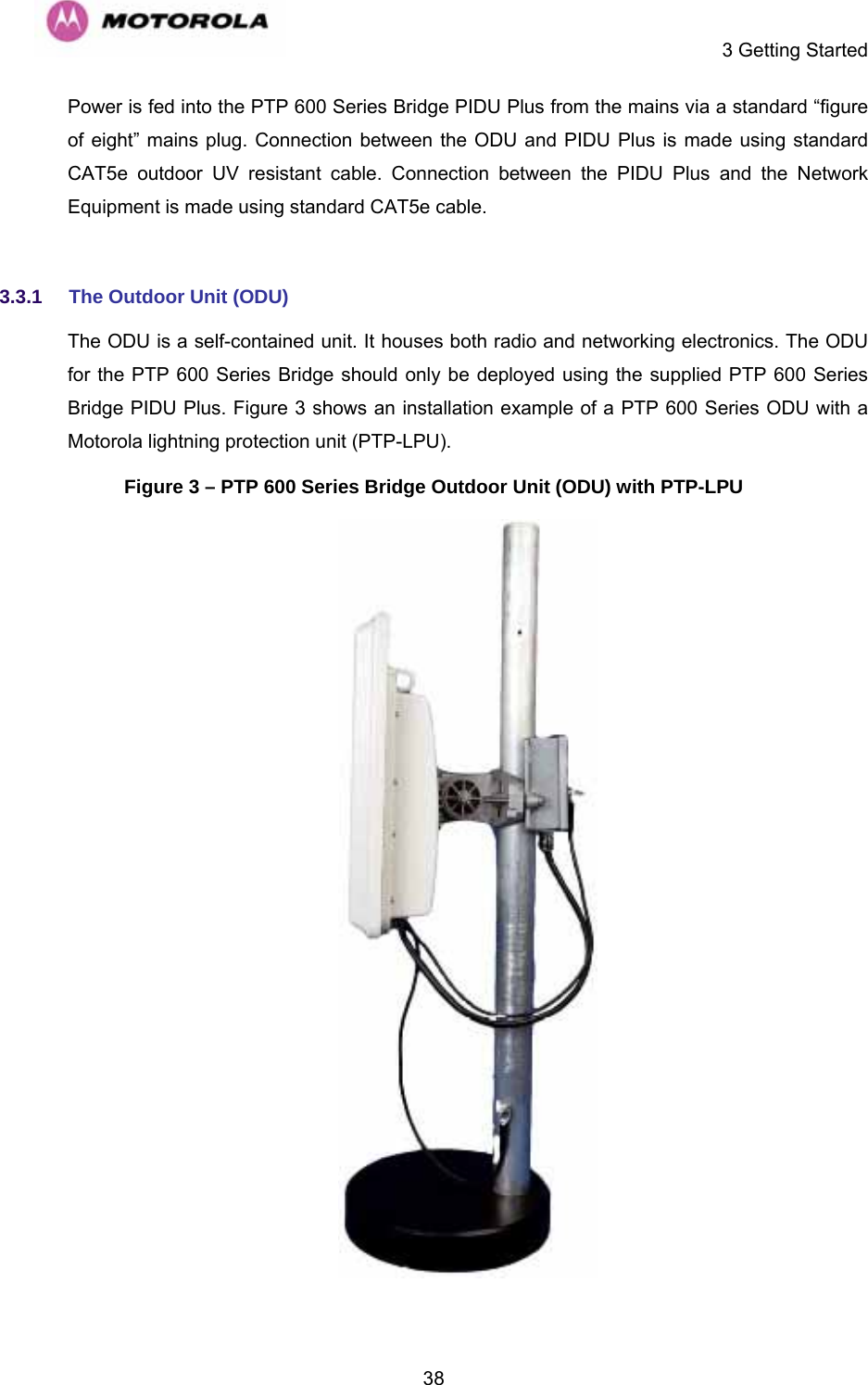
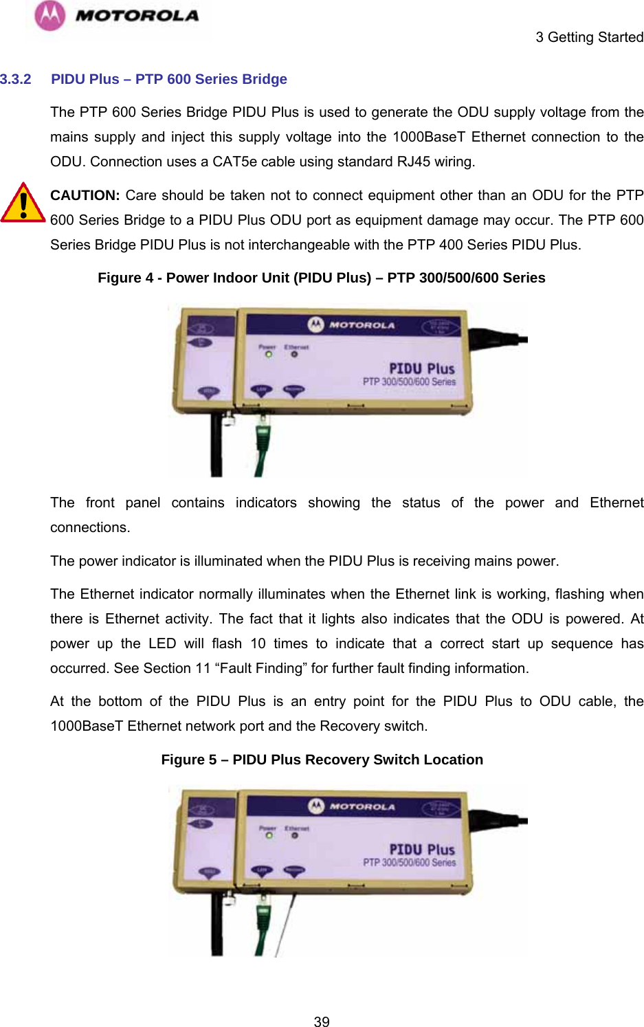
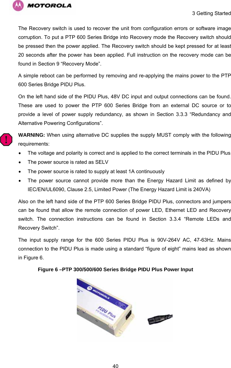
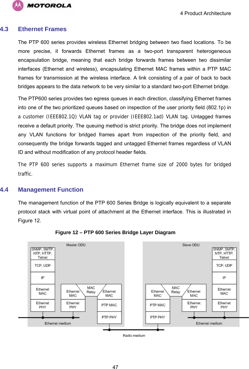
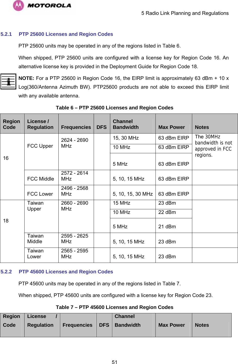
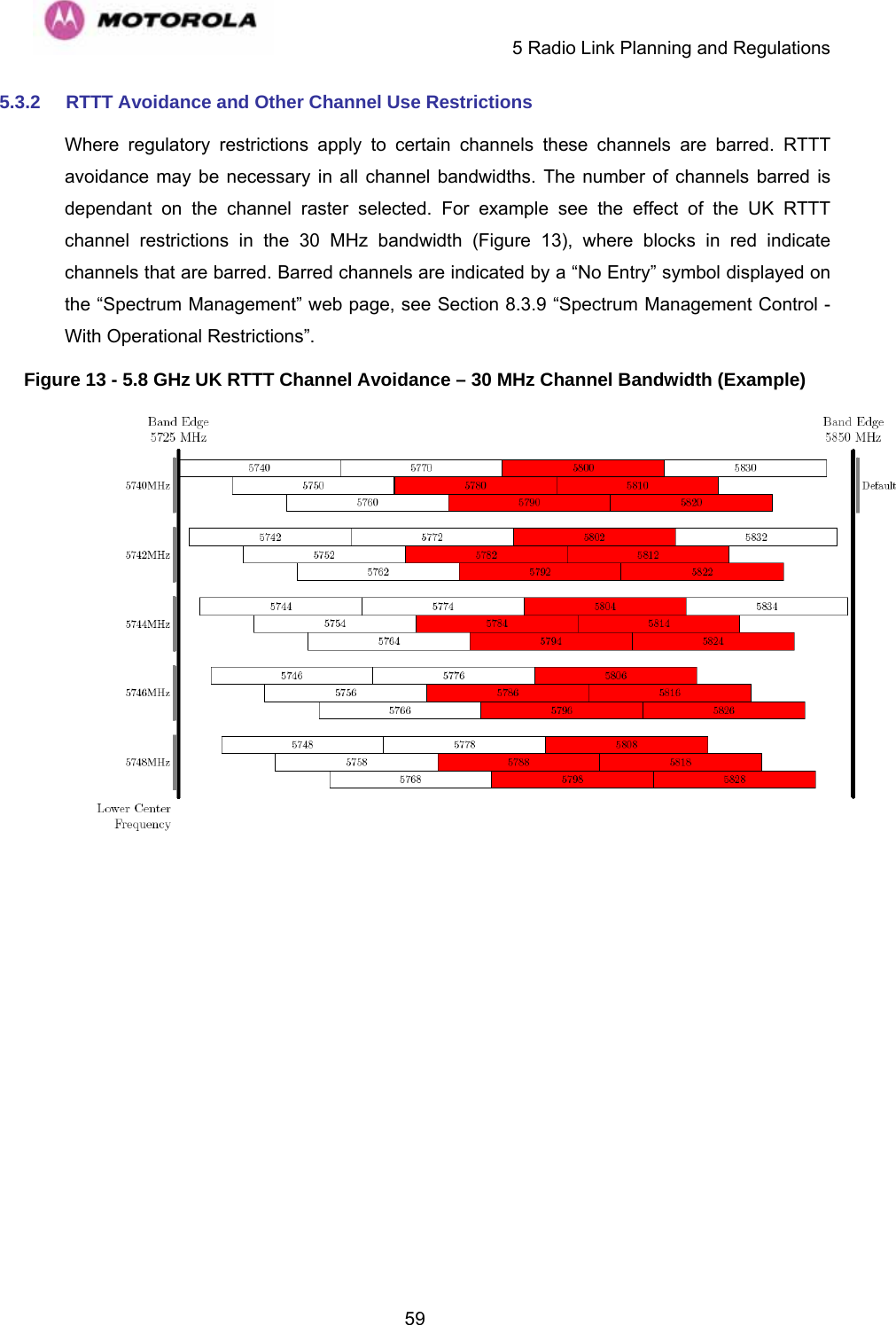
![3 Getting Started 37A PTP 600 Series Bridge system consists of a pair of identical devices that are deployed one at each end of the link. At installation, the user sets up one unit as the Master and the other as the Slave. Either unit can be configured as Master or Slave. Each end of the link consists of: • An integrated (or connectorized -see section 13) outdoor transceiver unit containing all the radio and networking electronics hereafter referred to as the Outdoor Unit (ODU). • An indoor connection box containing a mains power supply, status indicators and network connection port. Hereafter referred to as the Power Indoor Unit Plus (PIDU Plus). A pair of units is normally supplied pre-configured as a link. The network connection to a PTP 600 Series Bridge is made via a 1000BaseT Ethernet connection. Power is provided to the ODU over the 1000BaseT Ethernet connection using a patented non-standard powering technique. Previous releases of the PTP 600 Series Bridge platform used different powering and connection arrangements. Users of equipment prior to “Mod Record 1” should refer to the User Guide shipped with the original equipment. The “Mod Record” label can be found on the back of the ODU as shown in Figure 2. Figure 2 - Mod Record Label Alternatively, the network connection to a PTP 600 Series Bridge can be made using a 1000BaseSX Fiber Optic cable connected directly to the ODU. In this case power is still provided over the 1000BaseT Ethernet connection. In the case of Fiber Optic cable failure the PTP 600 Series Bridge will automatically fall back to the copper Ethernet connection (provided the cable length <=100m [330 ft]). “PTP 600 Series Optical Interface Upgrade Kits” can be obtained from your distributor, reseller or system integrator.](https://usermanual.wiki/Cambium-Networks/25601/User-Guide-1067252-Page-39.png)
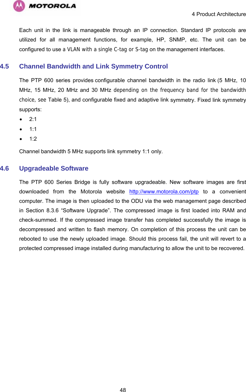
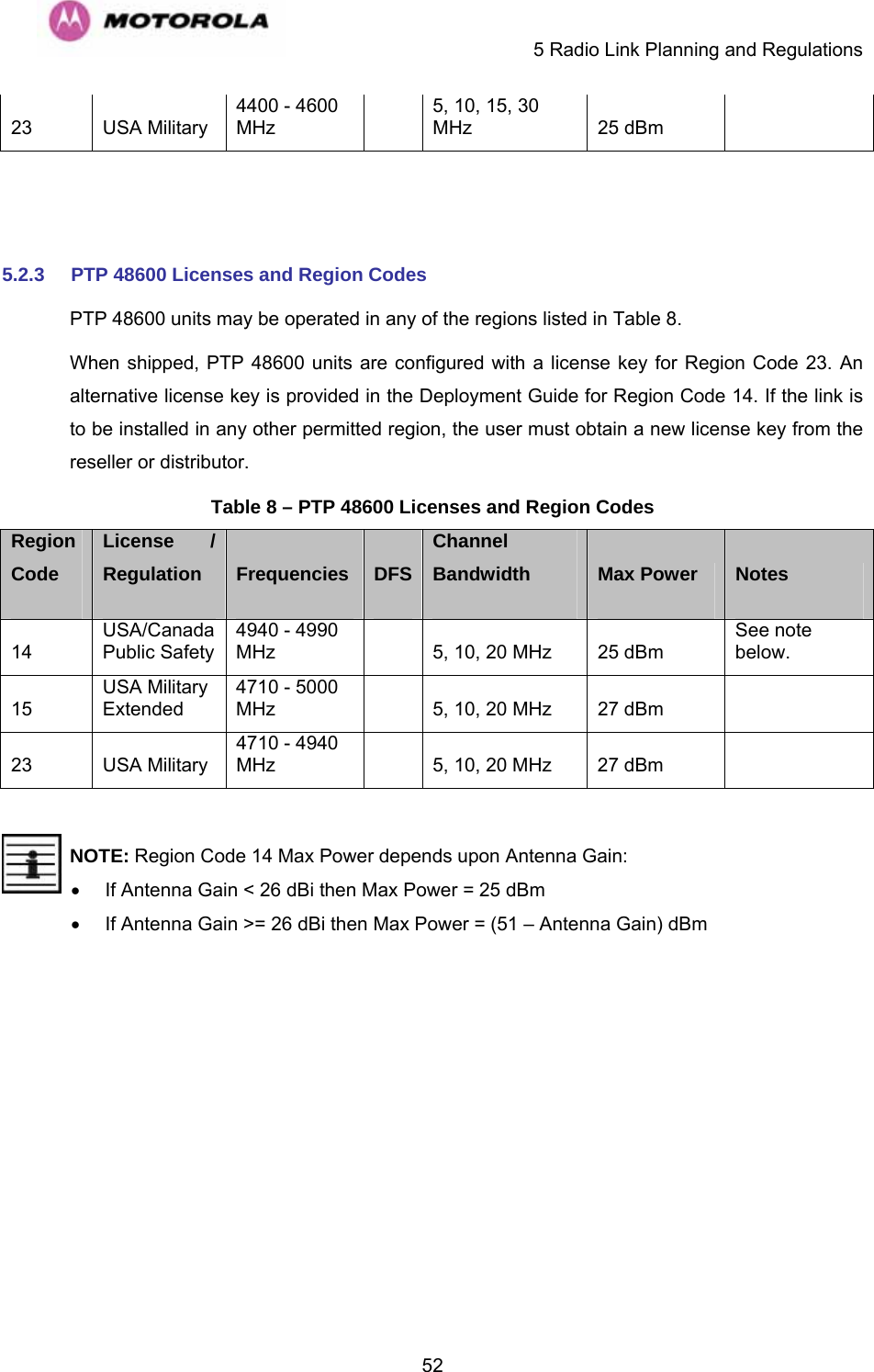
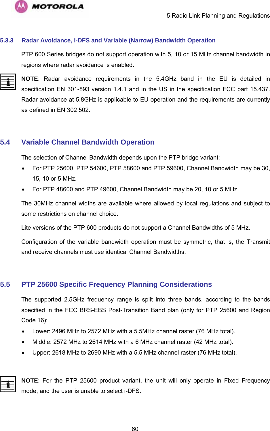

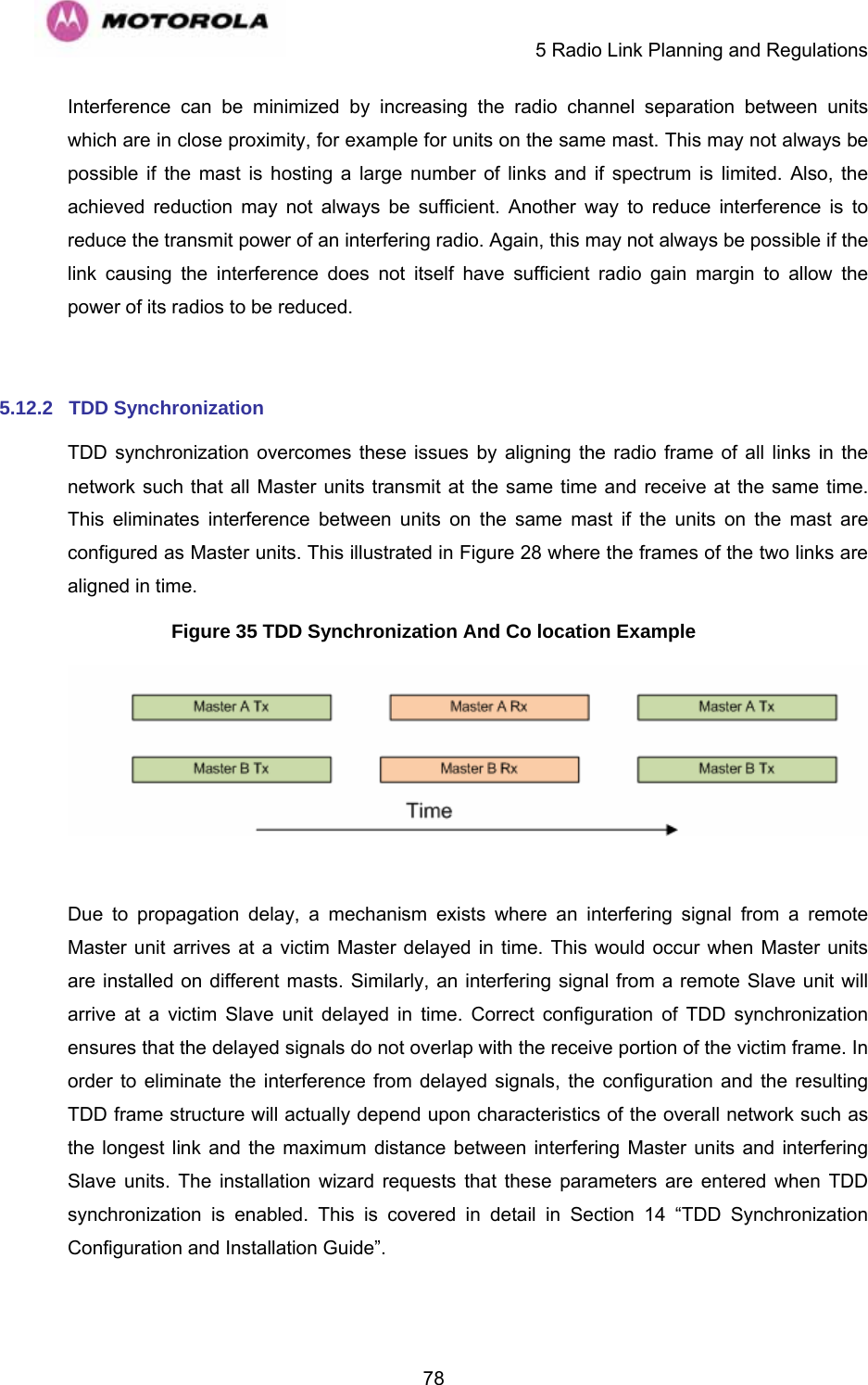


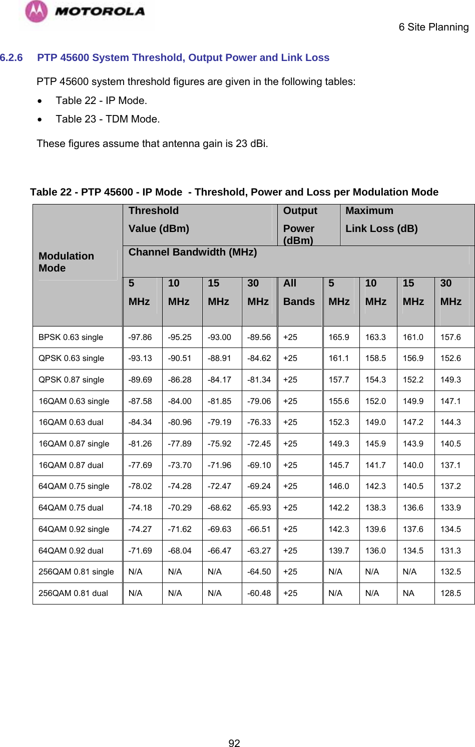
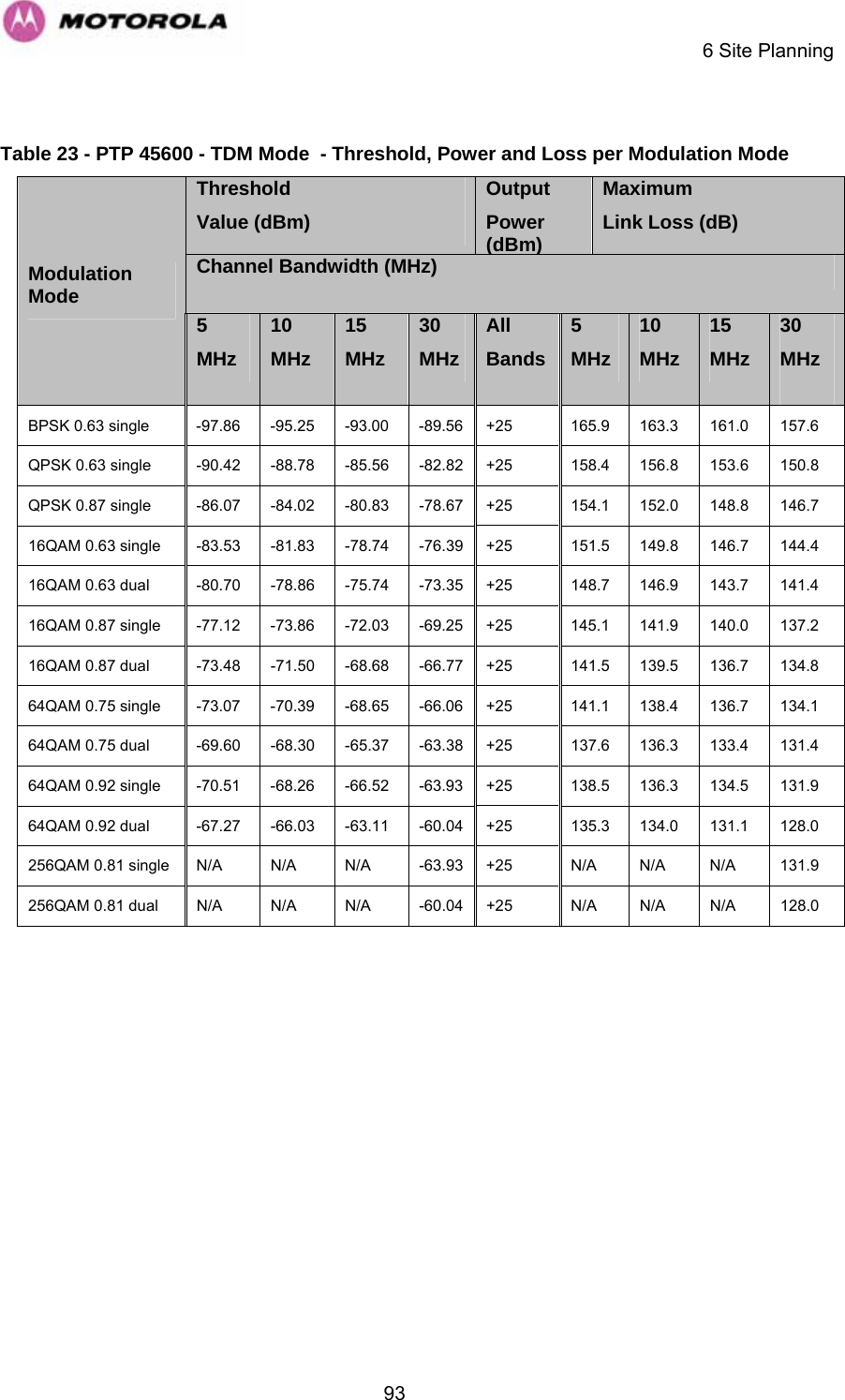
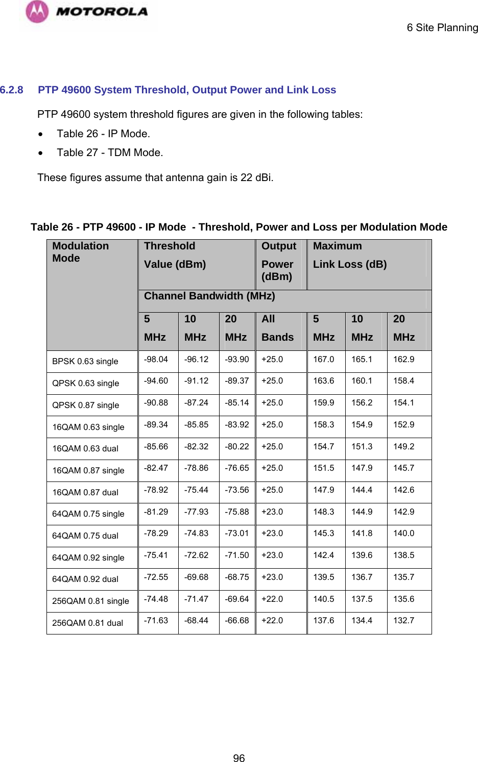
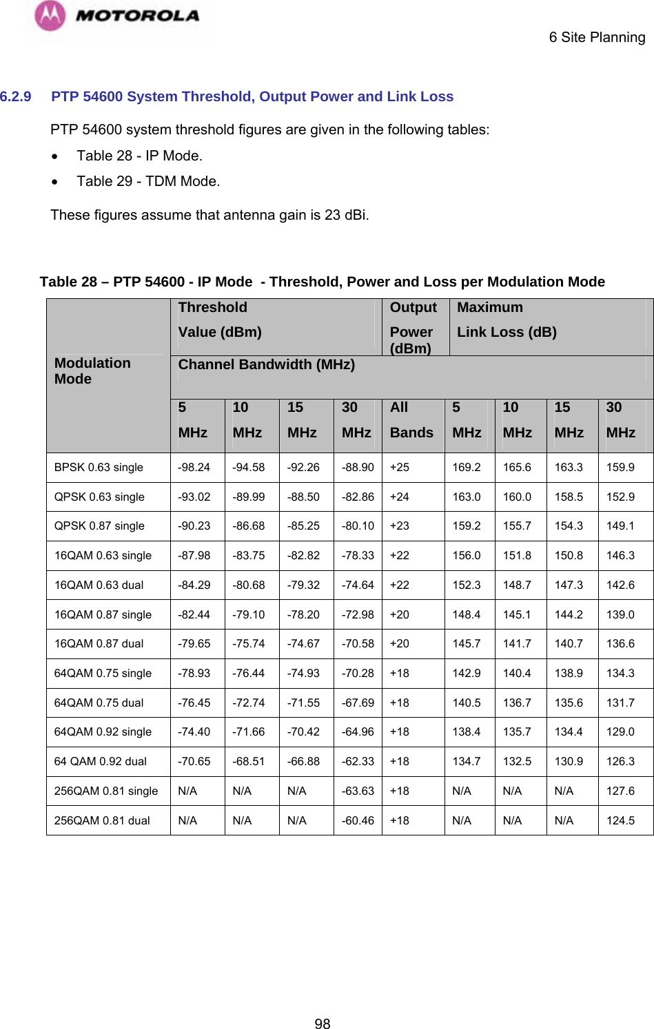
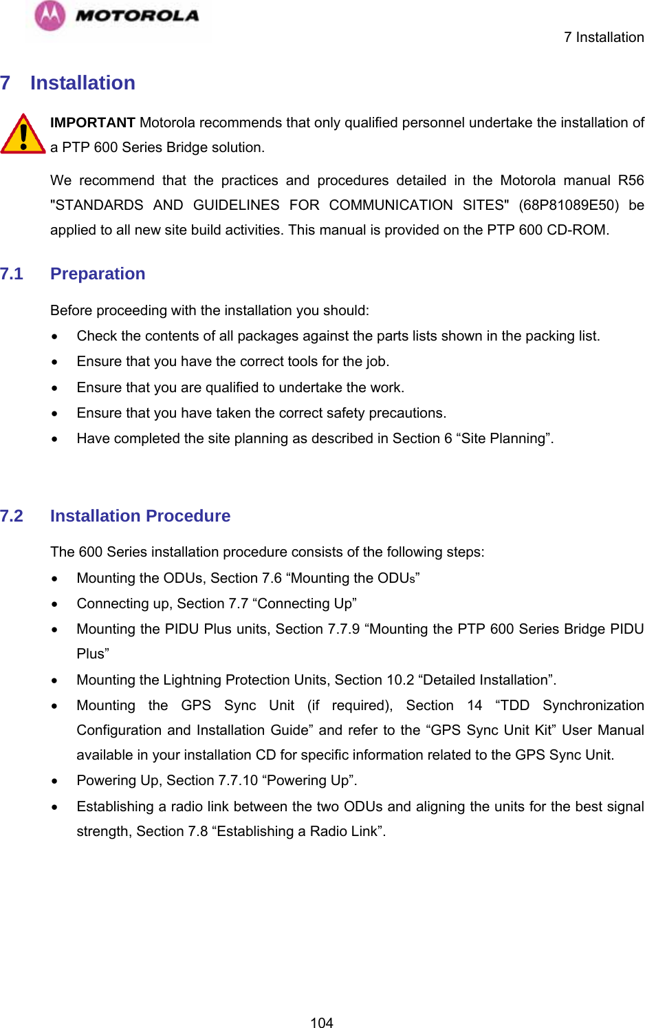
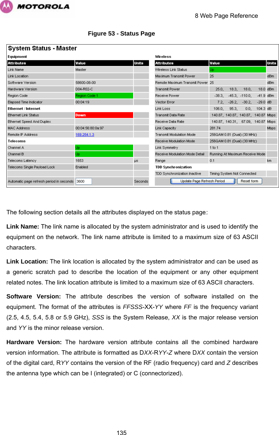
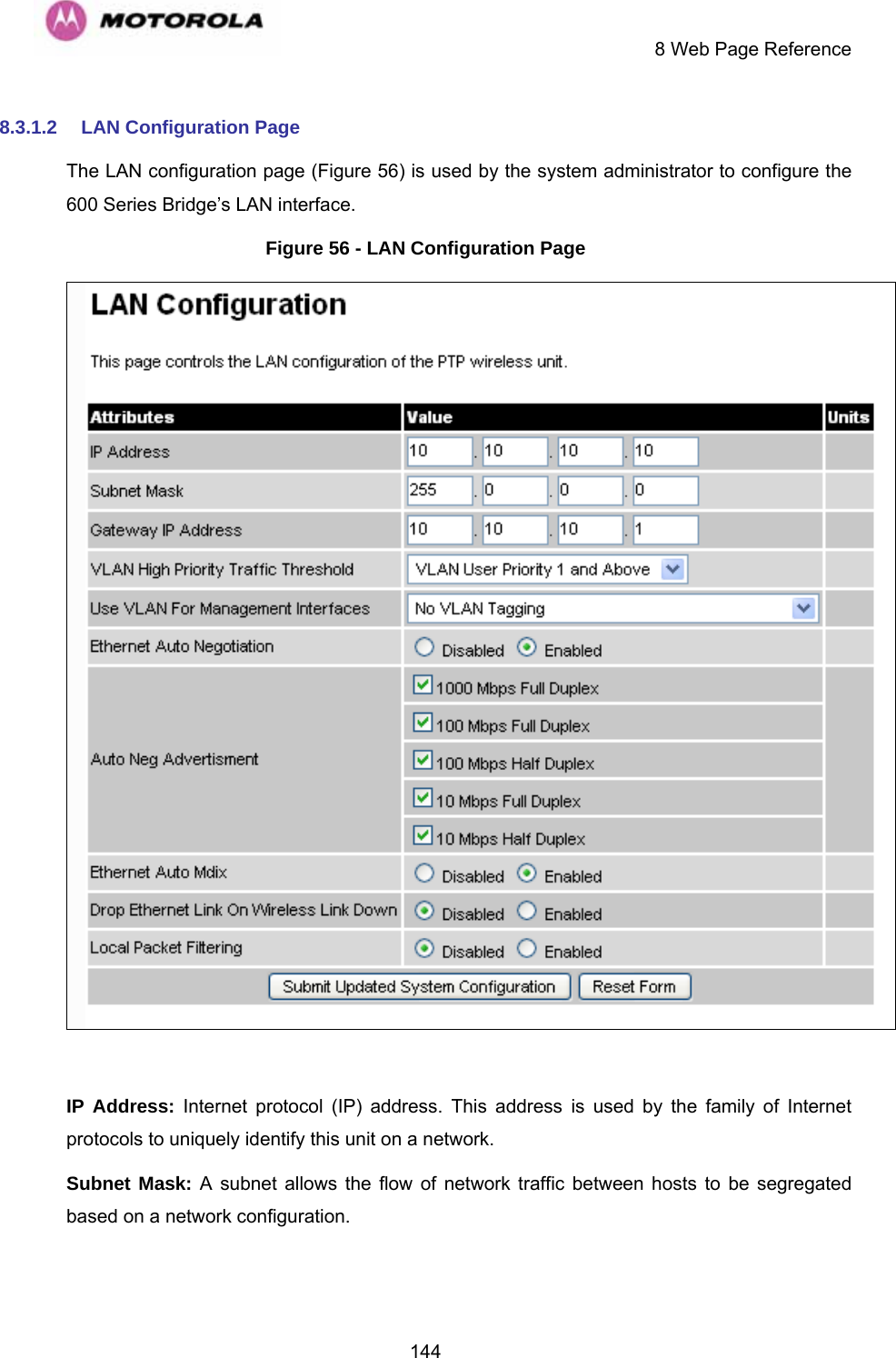
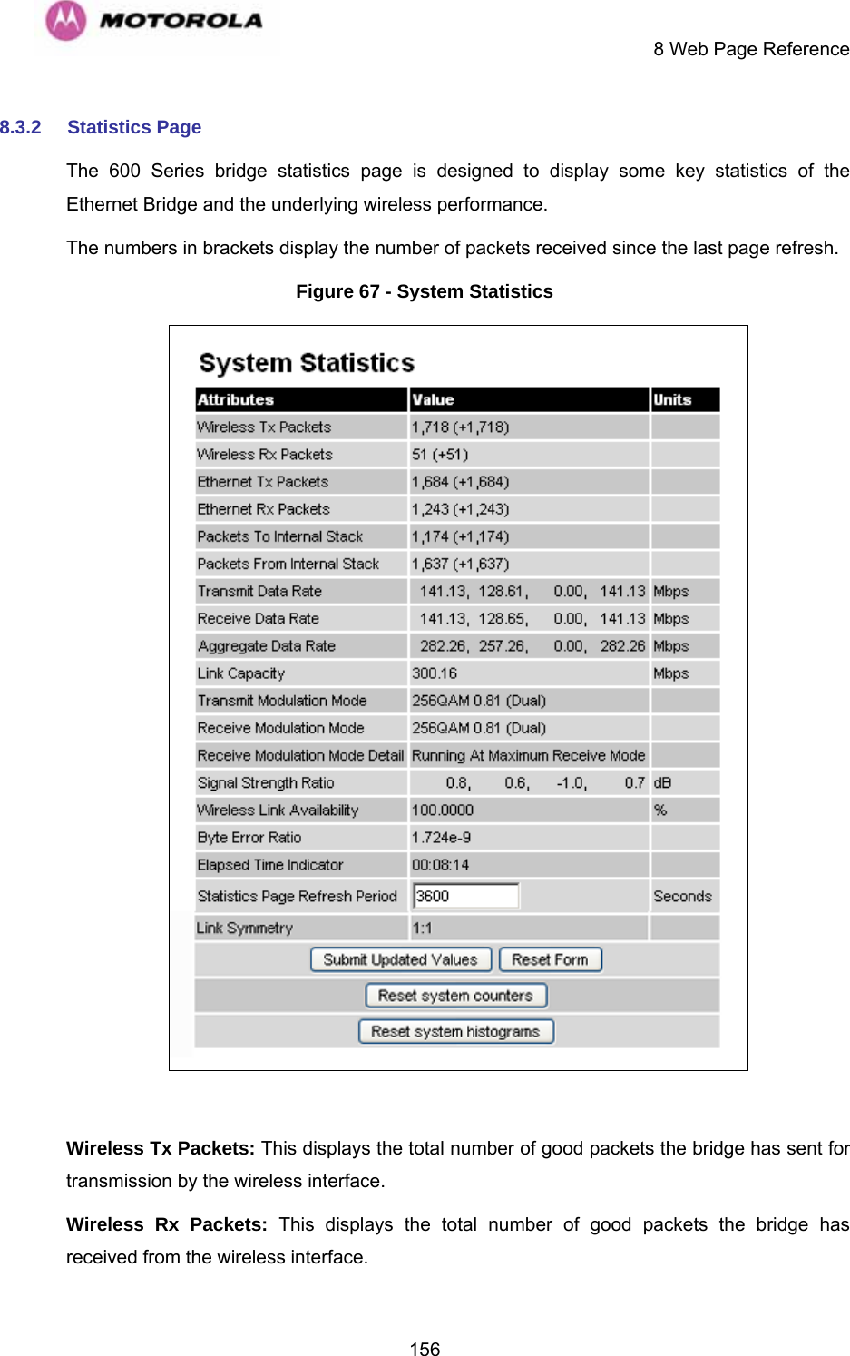
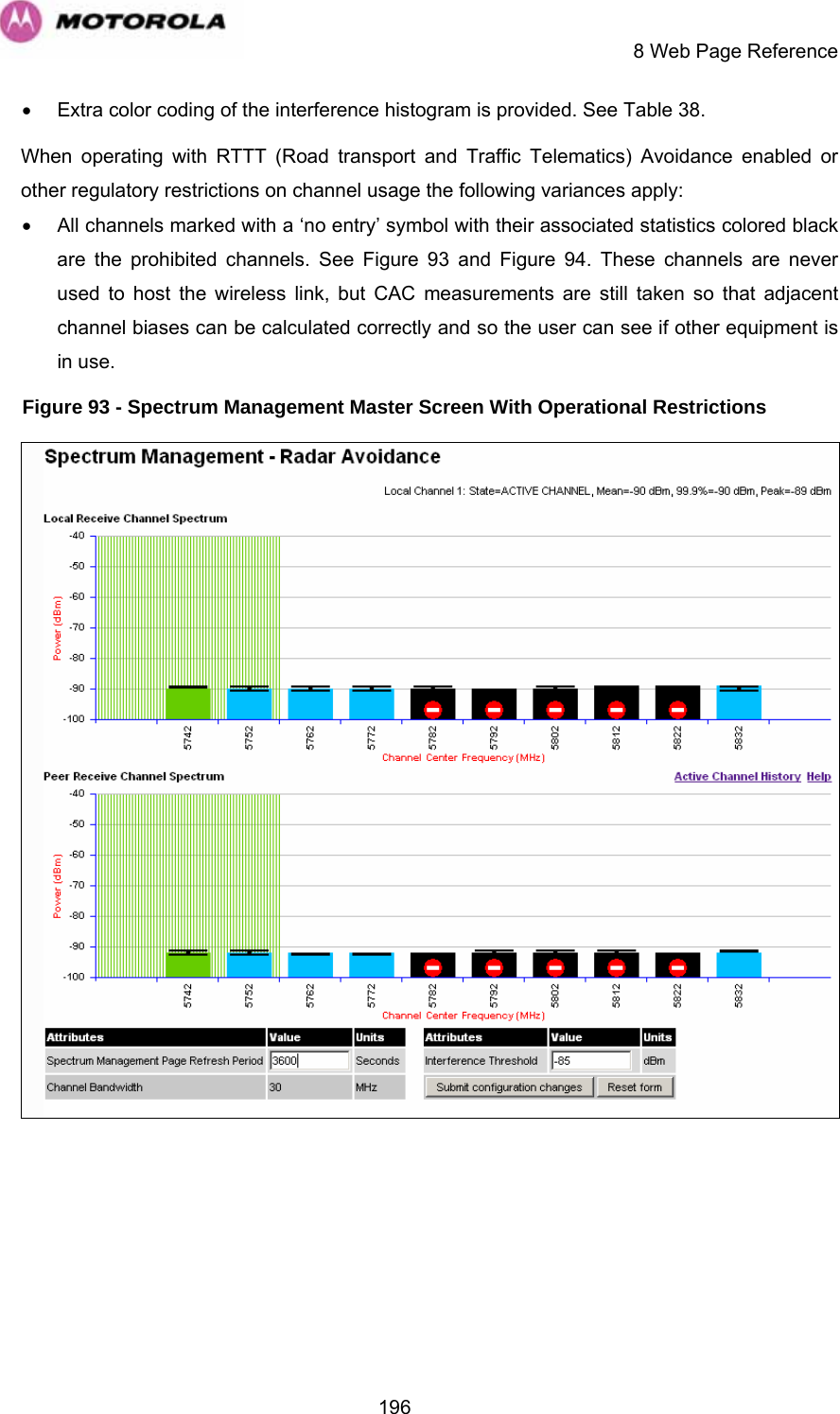
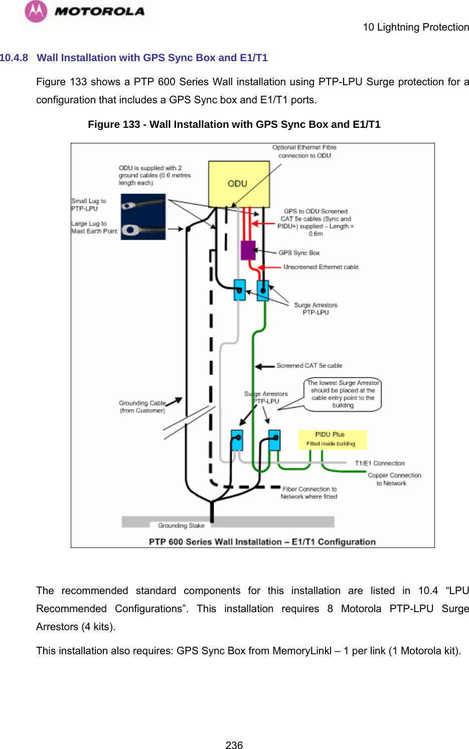
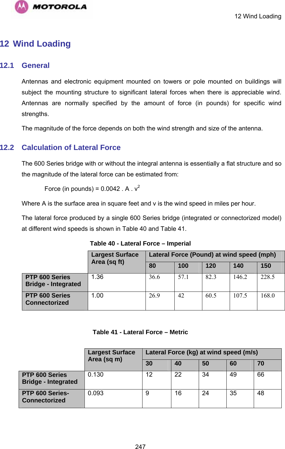
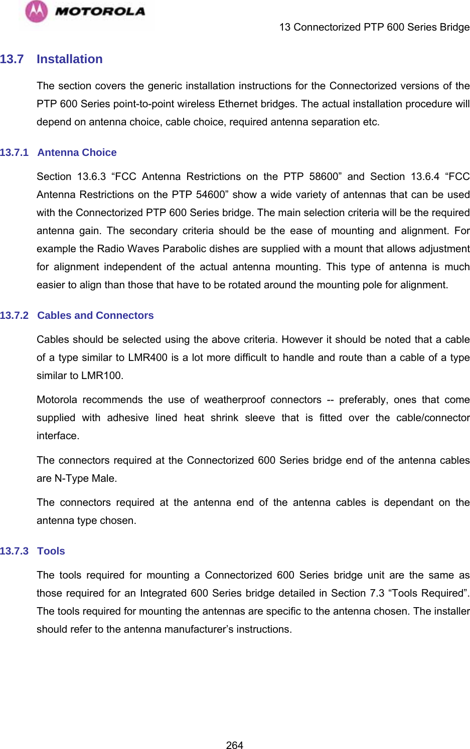
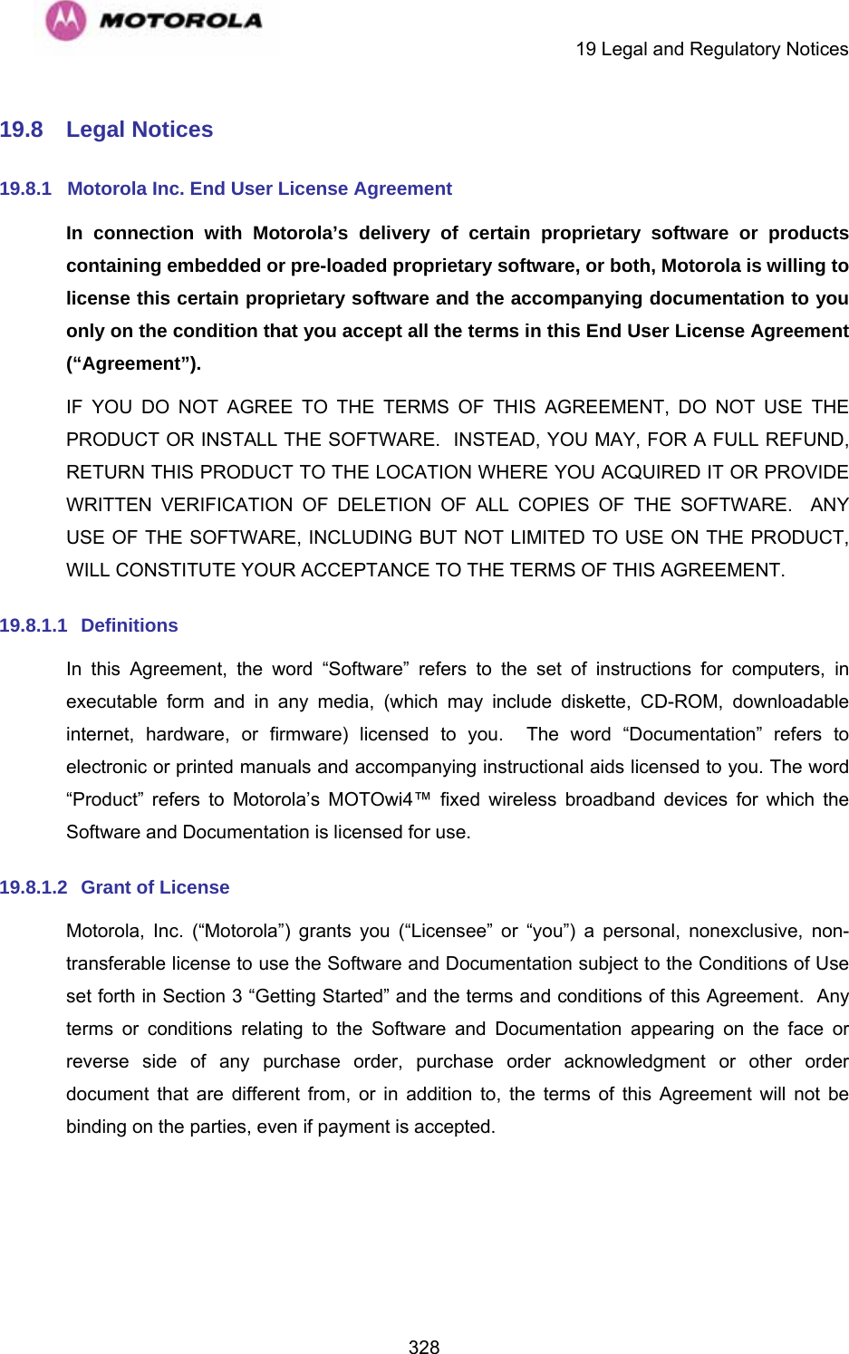
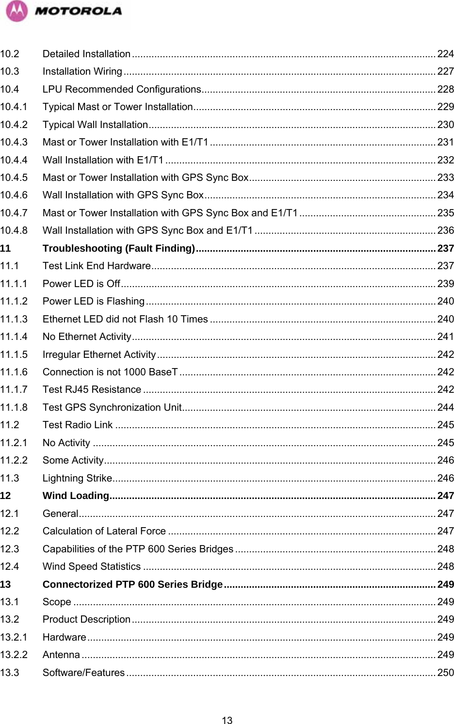
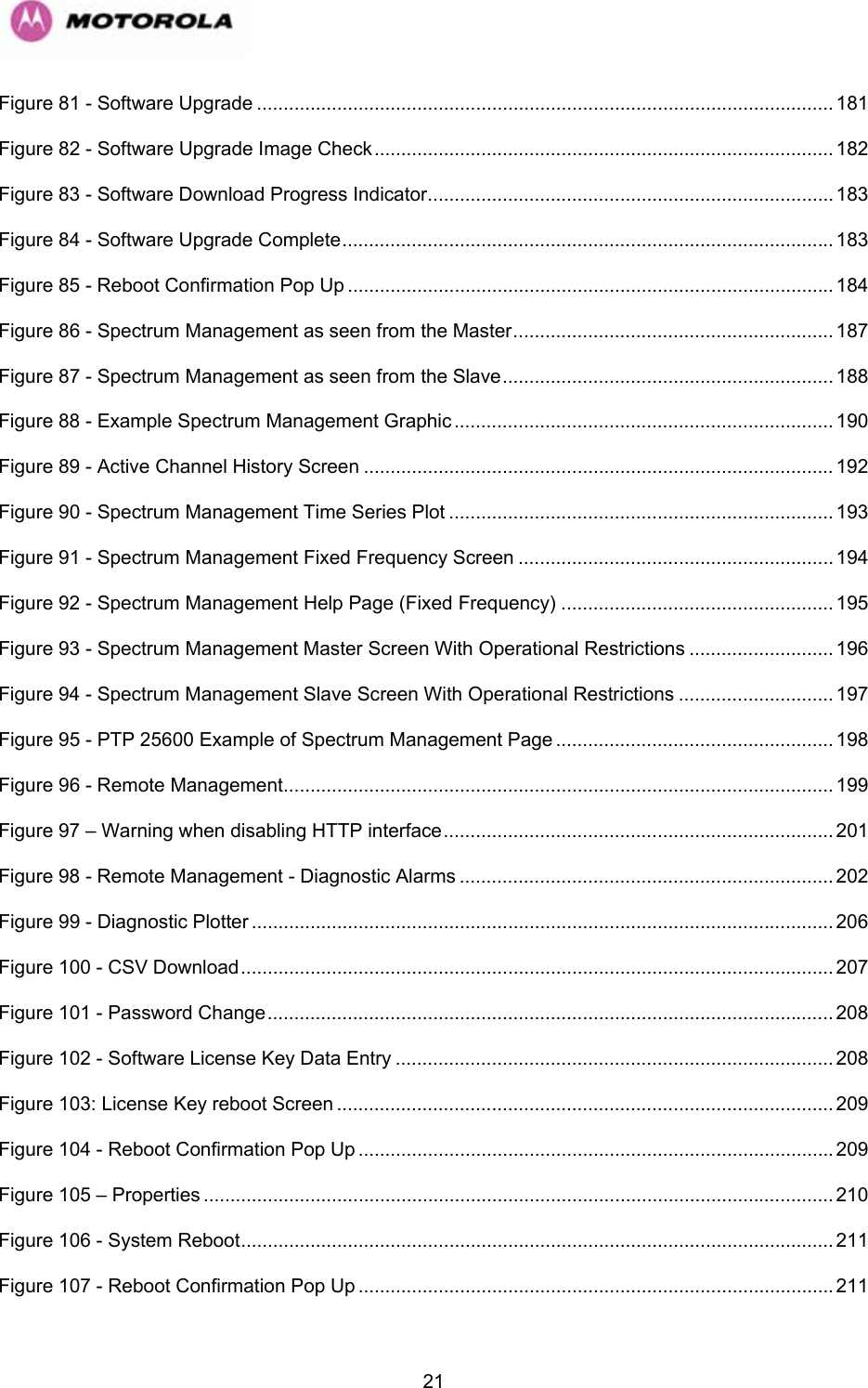
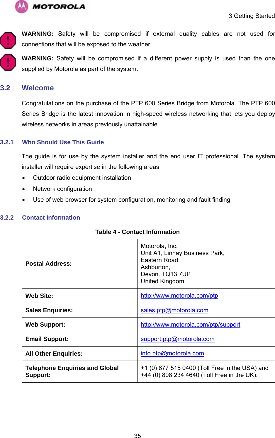
![6 Site Planning 876 Site Planning 6.1 Site Survey and Link Planning A site survey must be performed to identify all the obstructions (such as trees or buildings) in the path and to assess the risk of interference. This information is important if you are to achieve an accurate link feasibility assessment. The PTP 600 Series are designed to operate in Non-Line-of-Sight (NLoS) and Line-of-Sight (LoS) environments. Link planning enables a link of known quality to be installed. This involves the acquisition of path profile data (using Motorola’s free LINKPlanner utility). The LINKPlanner predicts data rates and reliability over the path. It allows the user to try different antenna heights and RF power settings. When the link is installed, the mean path loss can be checked to confirm that the predicted data rate and link reliability is achievable. Motorola LINKPlanner is available to download from http://www.motorola.com/ptp/support. 6.2 Site Selection Criteria The following are guidelines for selecting the installation location of the ODU and PIDU Plus for a PTP 600 Series Bridge. 6.2.1 ODU Site Selection When selecting a site for the ODU the following should be taken into consideration: • It is not possible for people to stand or walk inadvertently in front of the antenna • Height and location to achieve the best radio path • Height in relation to other objects with regard to lightning strikes • Aesthetics and planning permission issues • Distance from the ODU and connected Network equipment (Maximum cable run from the ODU to the connected equipment is 100m [330 ft]) • Distance from the PIDU Plus to the ODU (Maximum cable run from the PIDU Plus to the ODU is 300m [990 ft] when using the Fiber interface) • If using the GPS Sync Unit, ensure that it is exposed to an unobstructed path to the sky. Please refer to the “GPS Synchronization Unit Kit” User Manual delivered with the kit.](https://usermanual.wiki/Cambium-Networks/25601/User-Guide-1067252-Page-89.png)