Cambium Networks 49XX Point to Point Wireless Ethernet Bridge User Manual OS Gemini 5x45
Cambium Networks Limited Point to Point Wireless Ethernet Bridge OS Gemini 5x45
UserManual.wiki
>
Cambium Networks
>
49XX User Manual
Users Manual
Navigation menu
Upload a User Manual
Namespaces
Wiki Guide
HTML
PDF
Info
Views
User Manual
Discussion / Help
Navigation
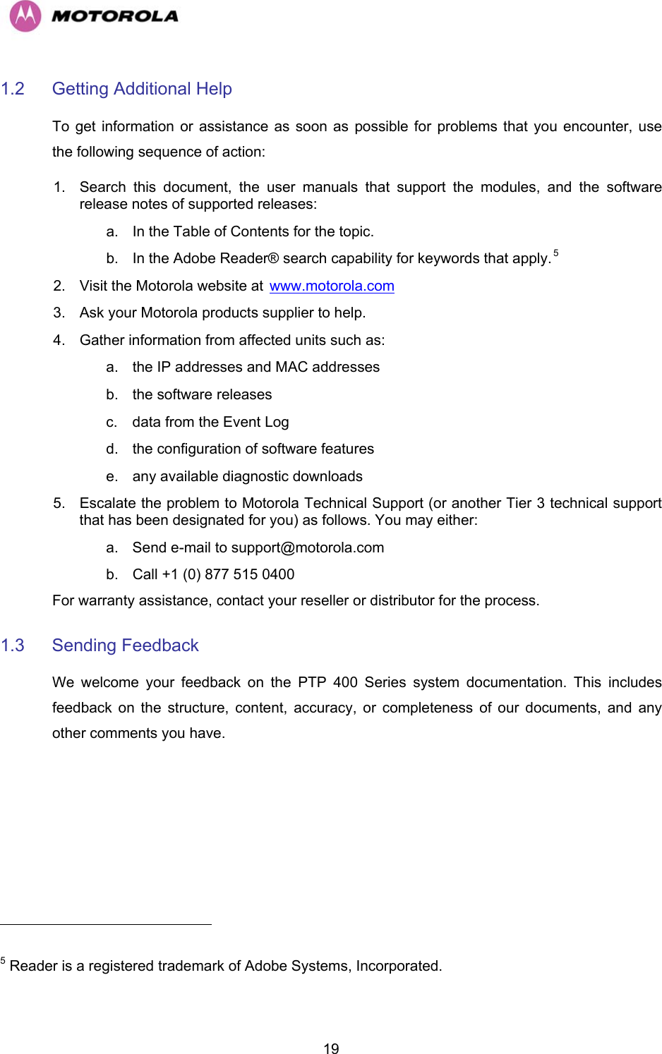
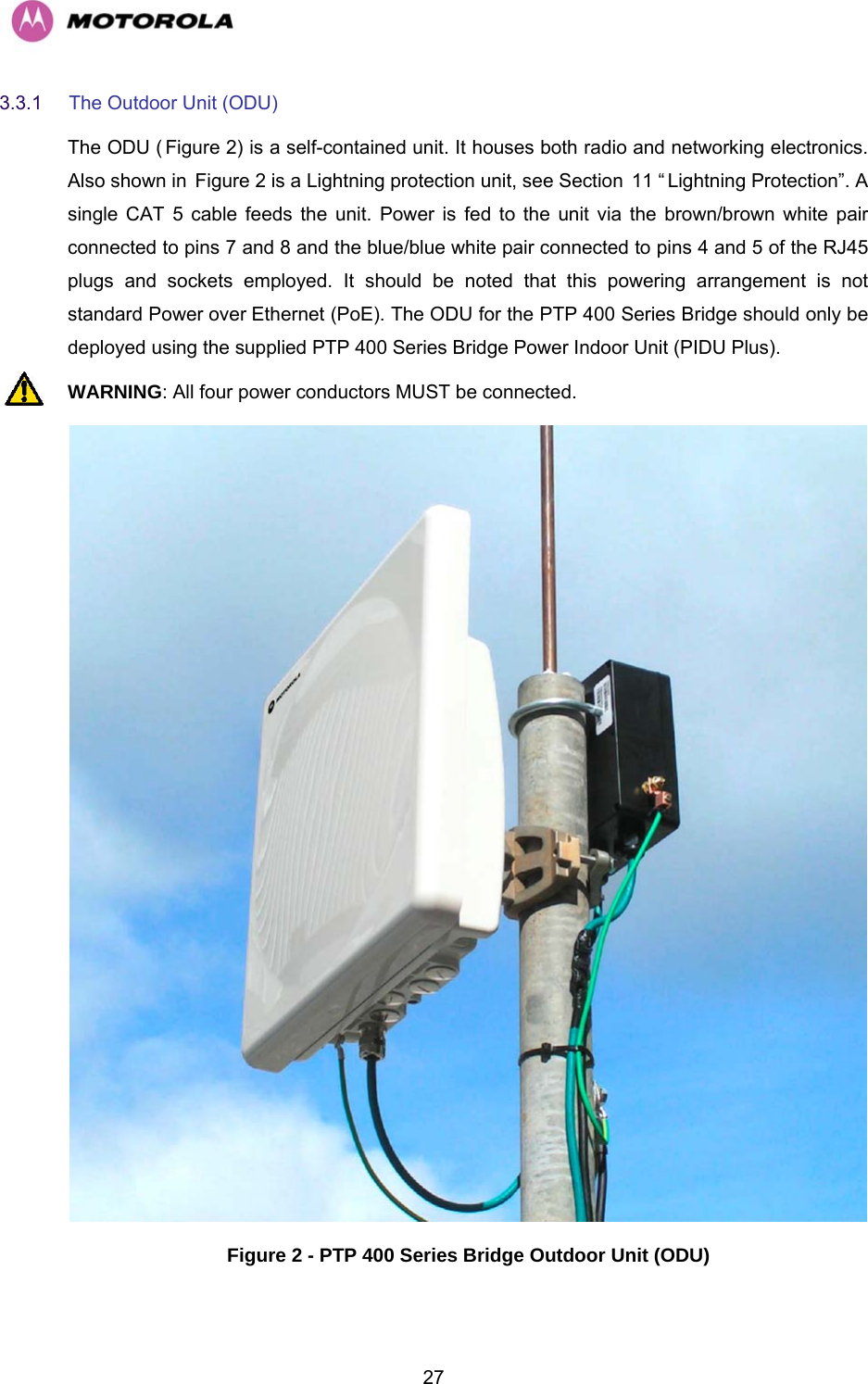
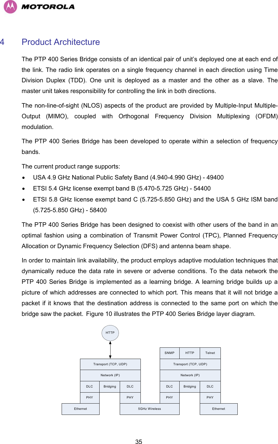

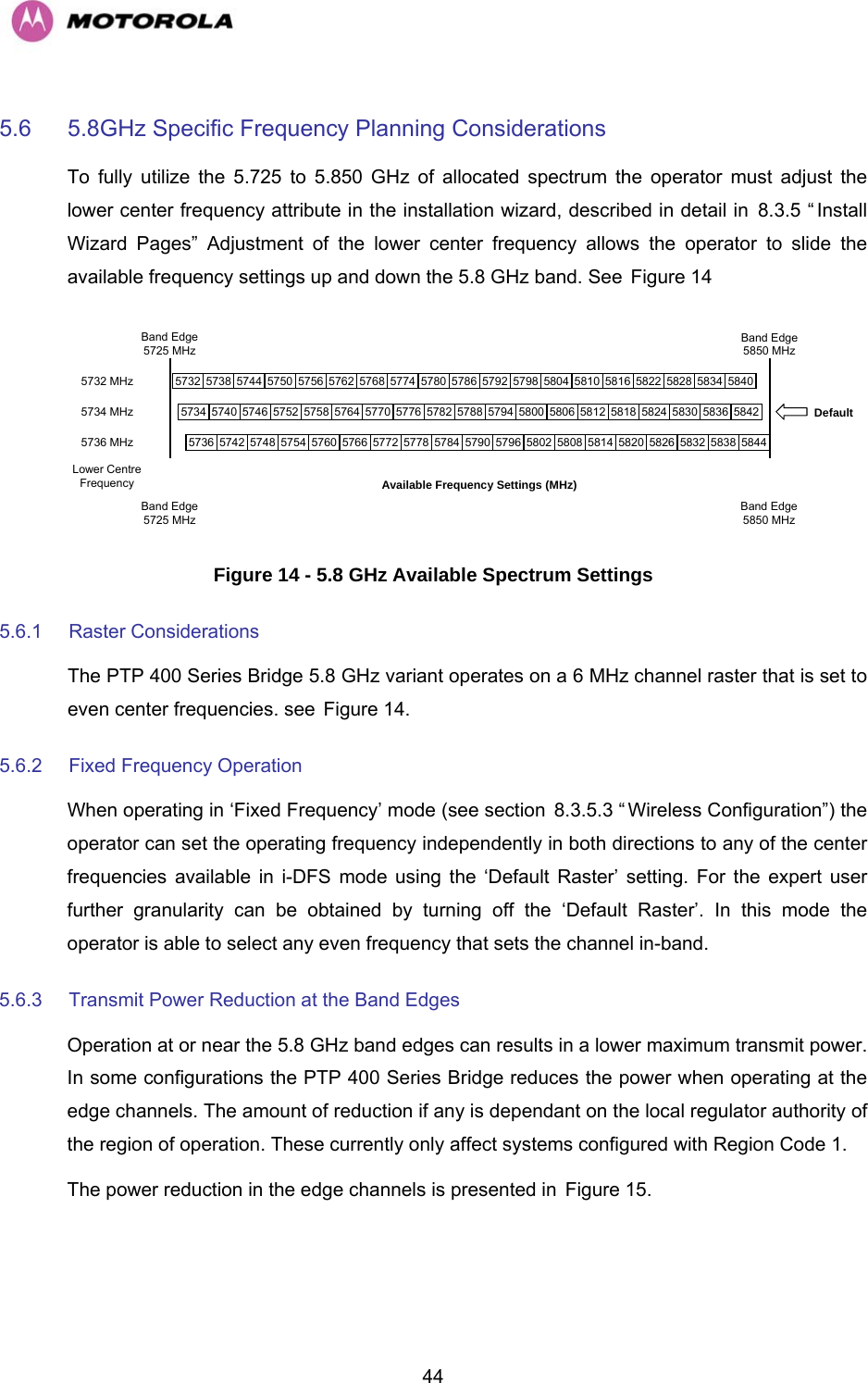
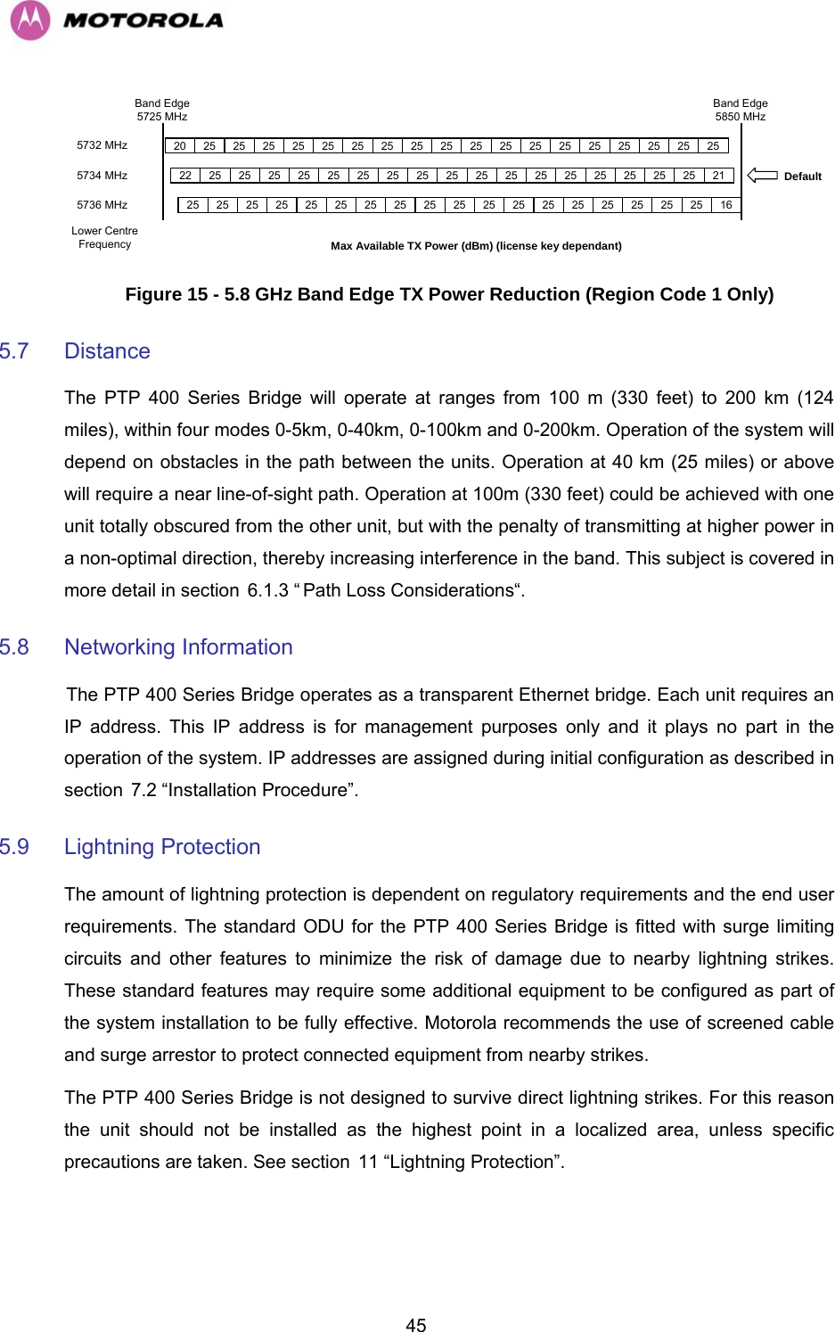
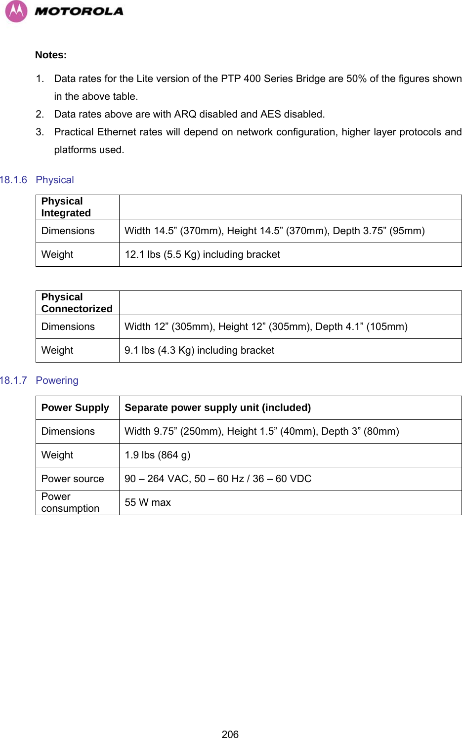
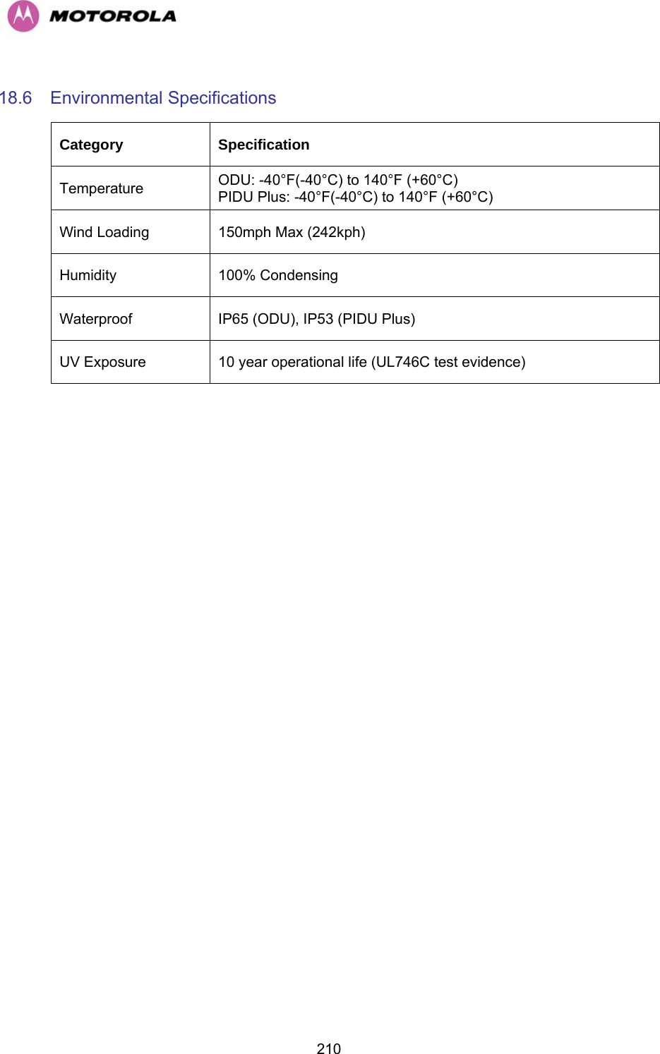
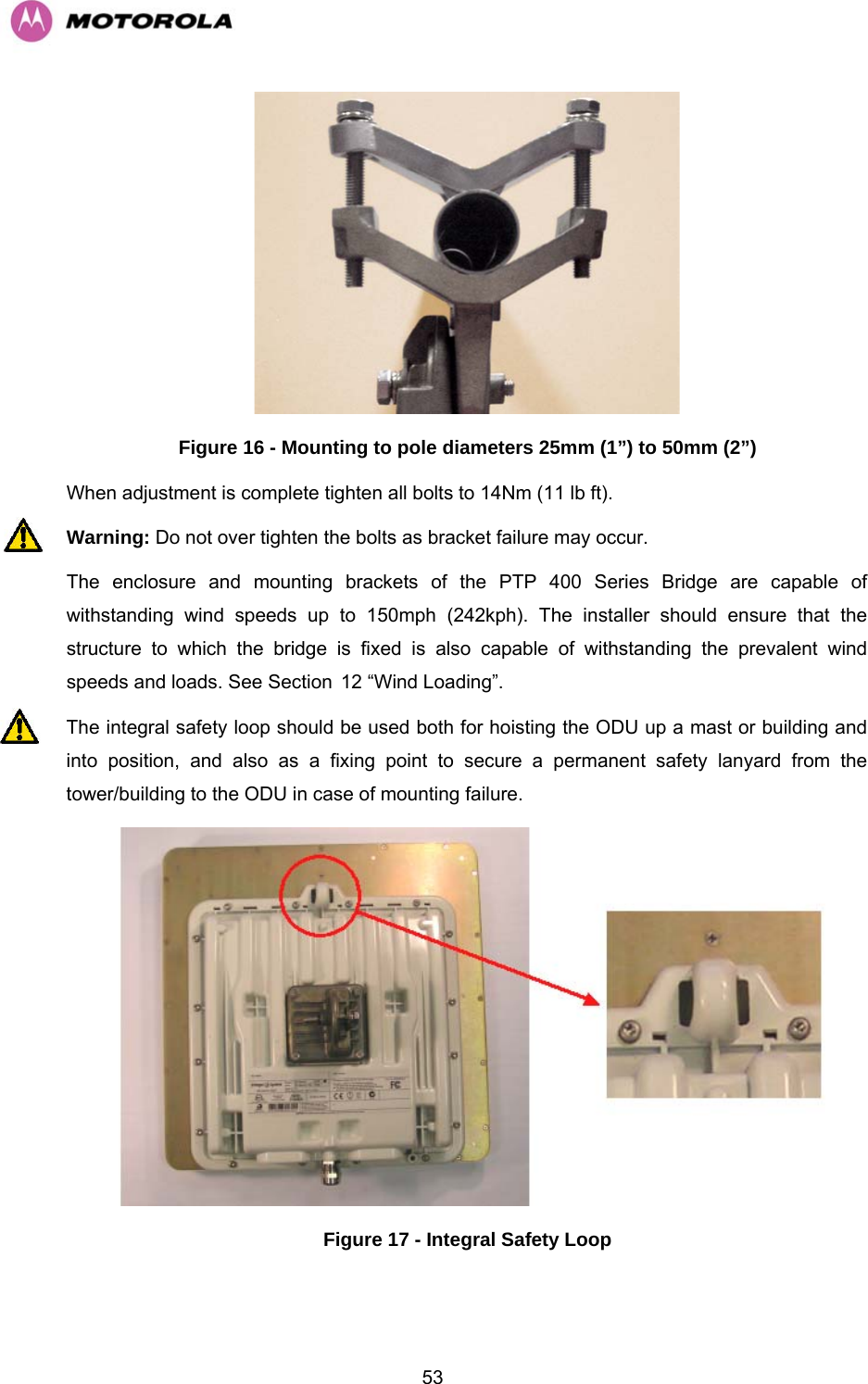
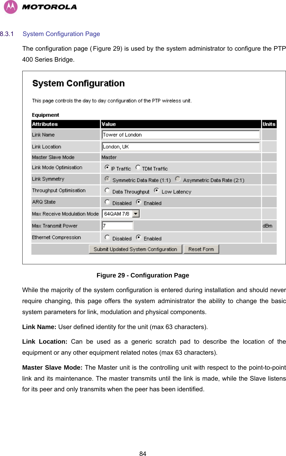
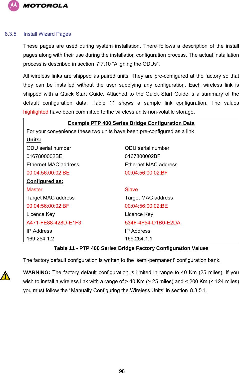
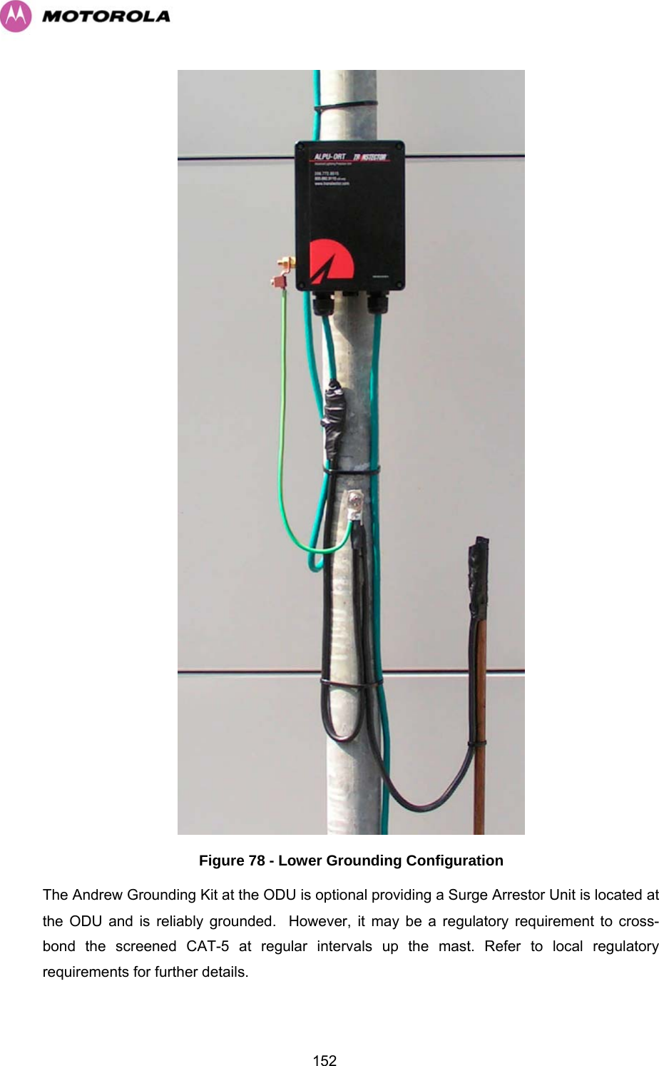
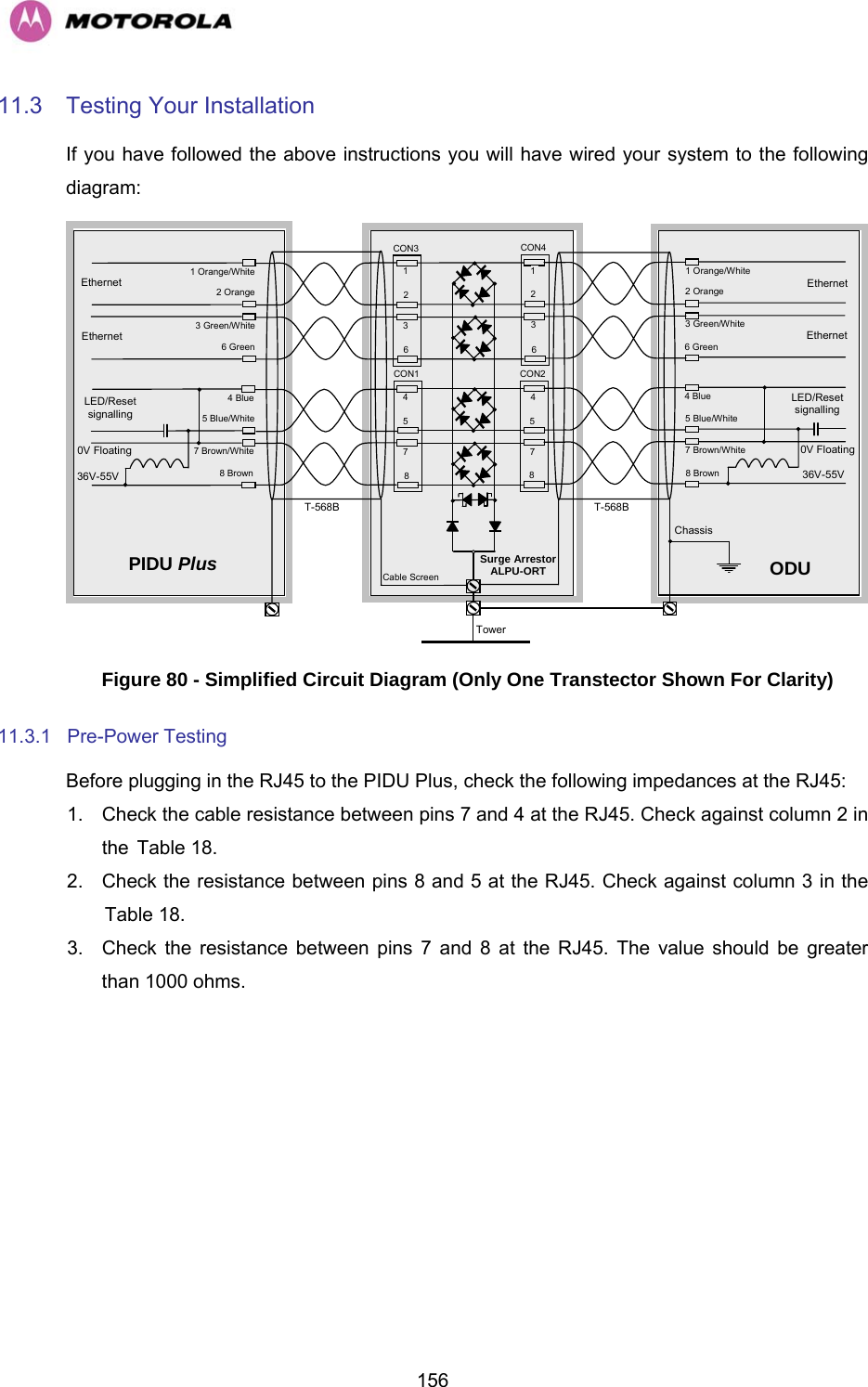
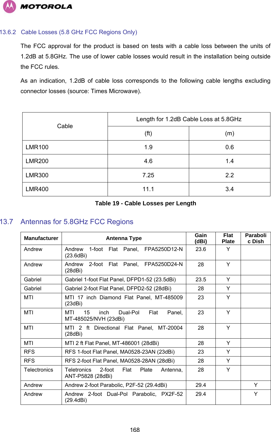
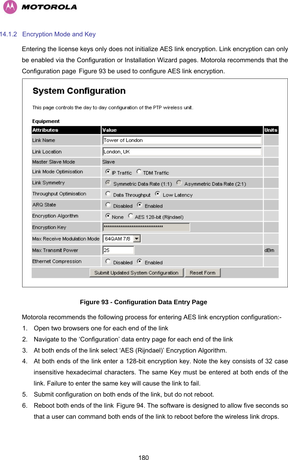
![476 Site Planning 6.1 Site Selection Criteria The following are guidelines for selecting the installation location of the ODU and PIDU Plus for the PTP 400 Series Bridge. 6.1.1 ODU Site Selection When selecting a site for the ODU the following should be taken into consideration: • That it is not possible for people to stand or walk inadvertently in front of the antenna. • Height and location to achieve the best radio path • Height in relation to other objects with regard to lightning strikes • Protection from the weather • Aesthetics and planning permission issues • Distance from the PIDU Plus and connected equipment (Maximum cable run ODU to connected equipment is 100m [330 feet]) • Distance from the PIDU Plus to the ODU (Maximum cable run from the PIDU Plus to the ODU is 100m [330 feet] minus the length of the cable from the PIDU Plus to the connected equipment) 6.1.2 PTP 400 Series BridgePIDU Plus Site Selection When selecting a site for the PIDU Plus the following should be taken into consideration: • Availability of a mains electricity supply • Accessibility for viewing status indicators and pressing reset switch (See section H3.3.2 “The Power Indoor Unit (PIDU Plus)” and section H9 “Fault Finding” • Distance from ODU and connected equipment (Maximum cable run ODU to connected equipment is 100m [330 feet]) • Distance from the ODU to the PIDU Plus (Maximum cable run from the ODU to the PIDU Plus is 100m [330 feet] minus the length of the cable from the PIDU Plus to the connected equipment)](https://usermanual.wiki/Cambium-Networks/49XX/User-Guide-710871-Page-49.png)
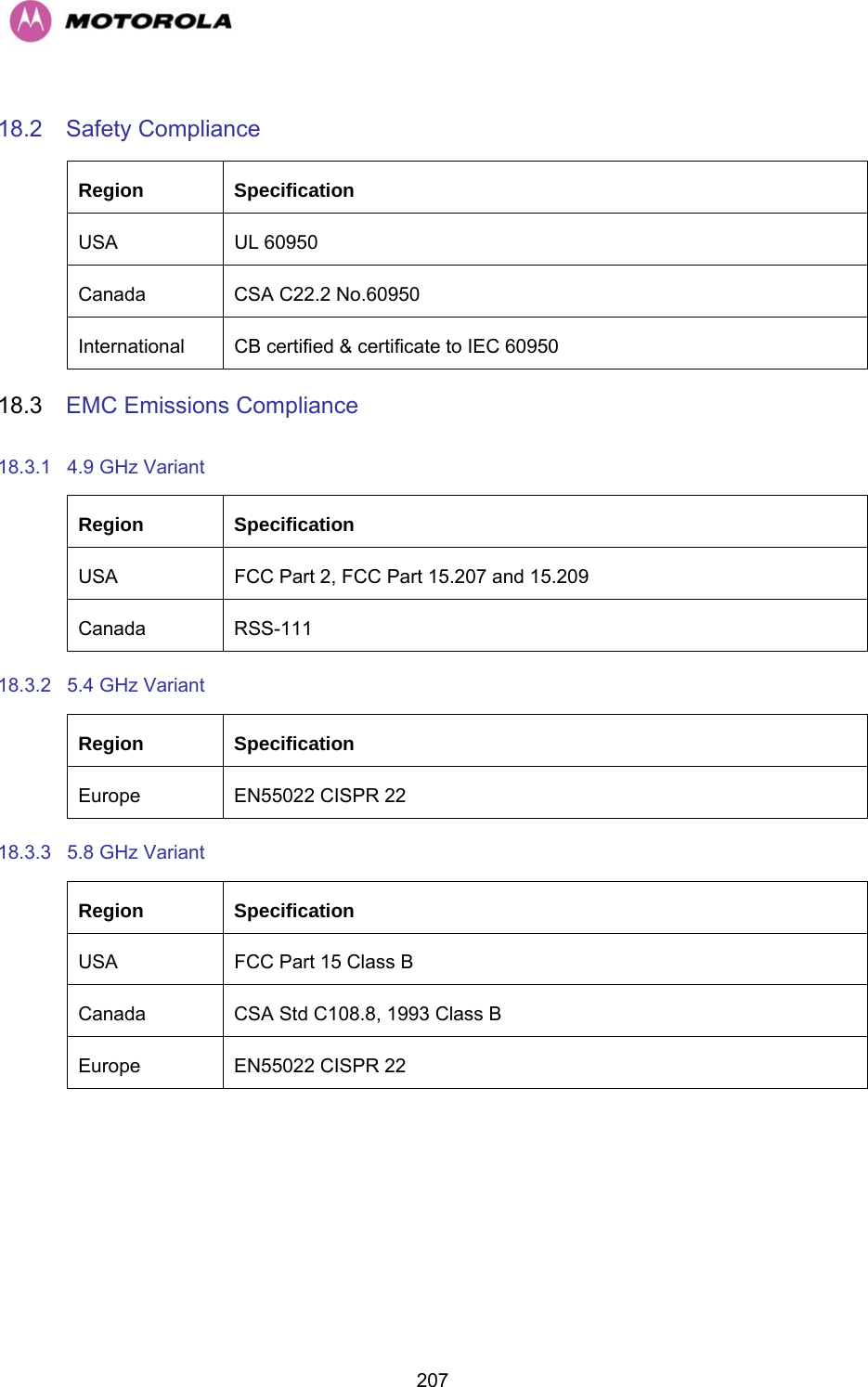
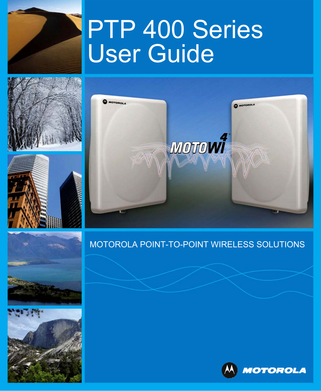
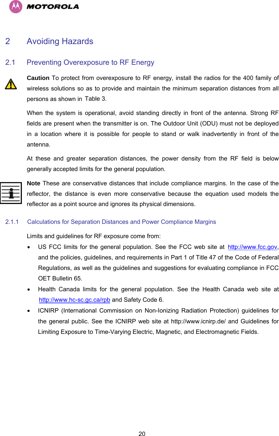
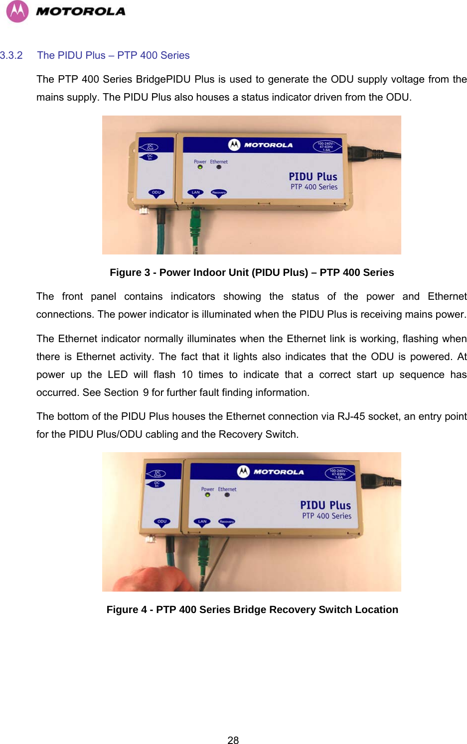
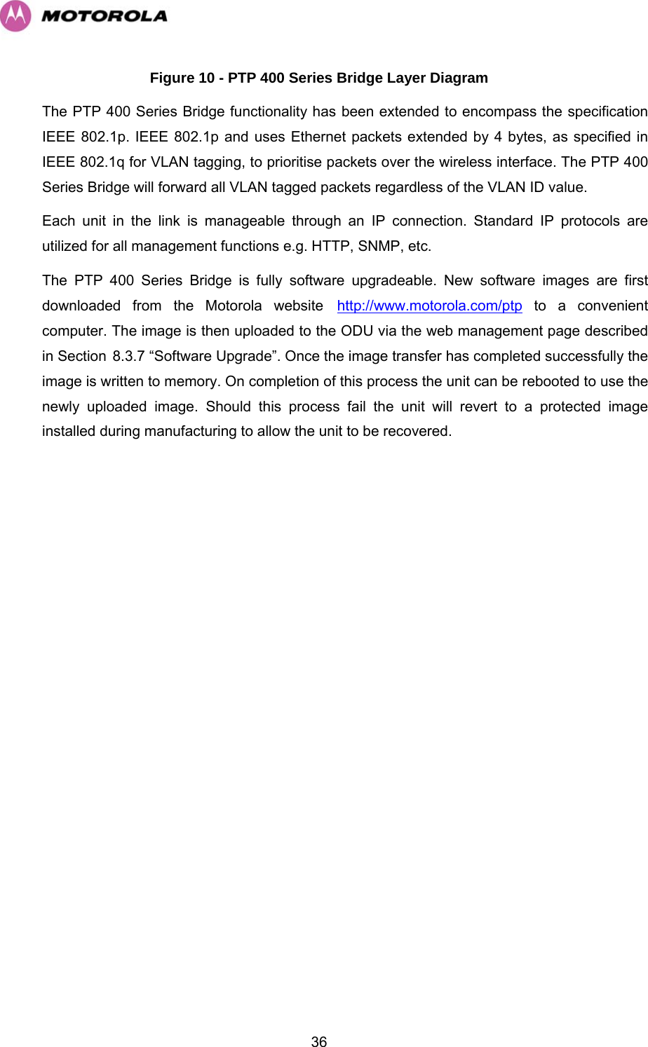
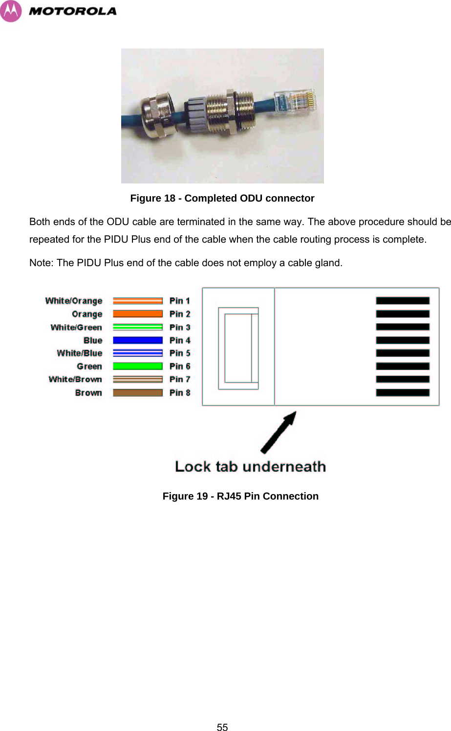
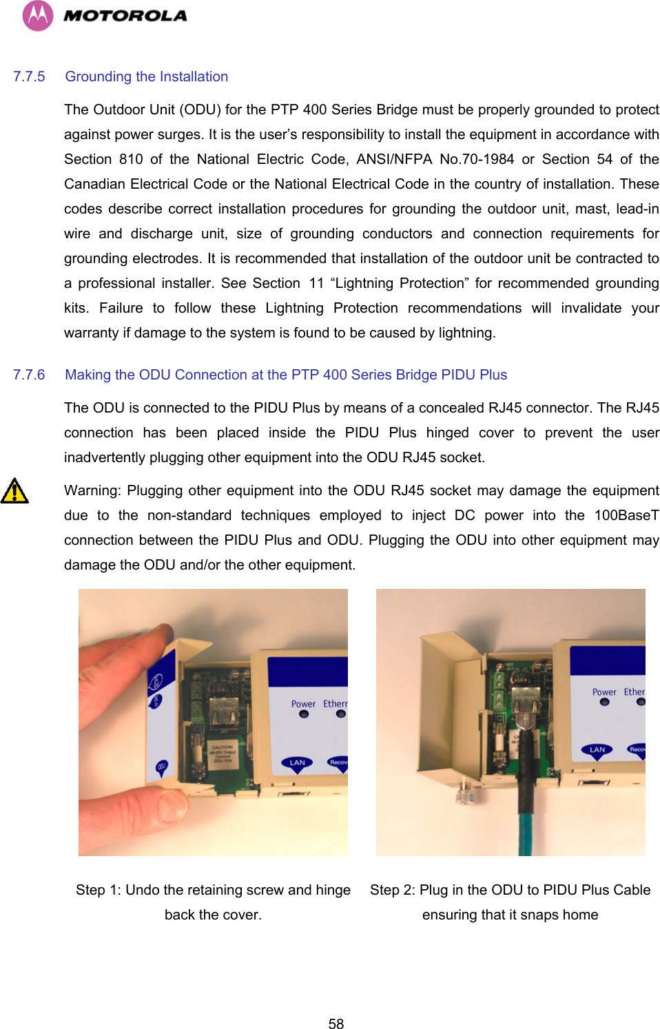
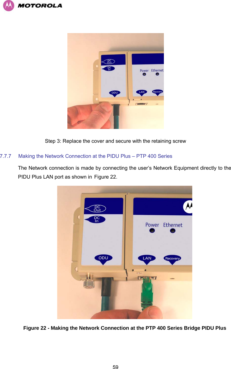
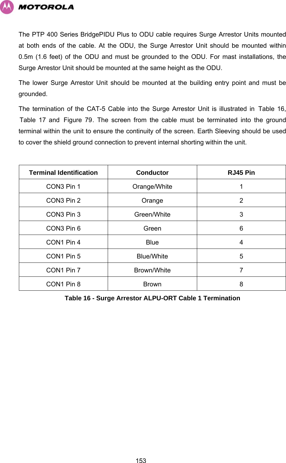
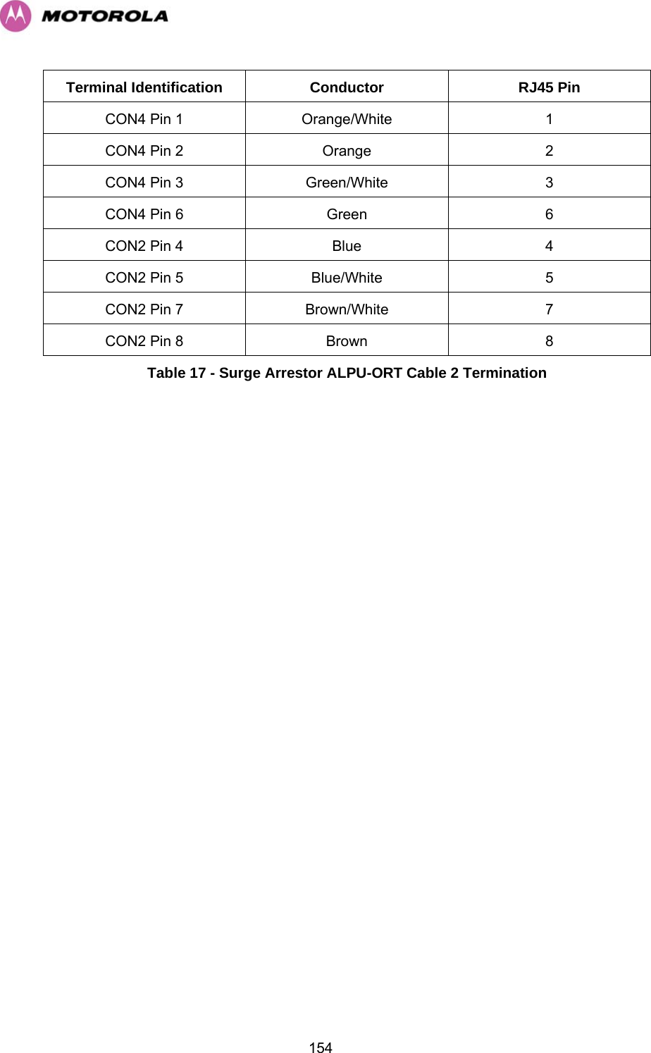
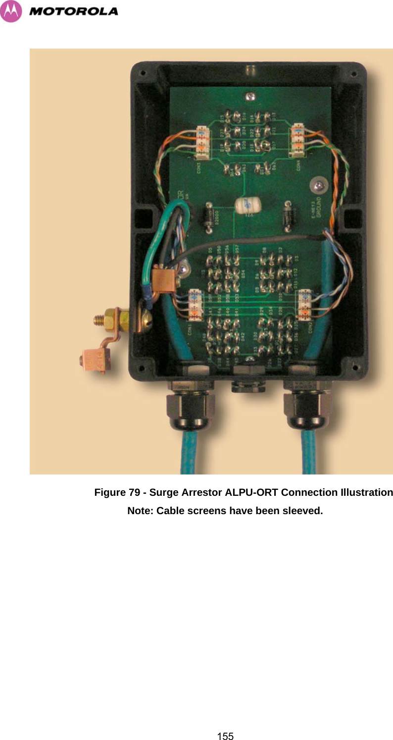
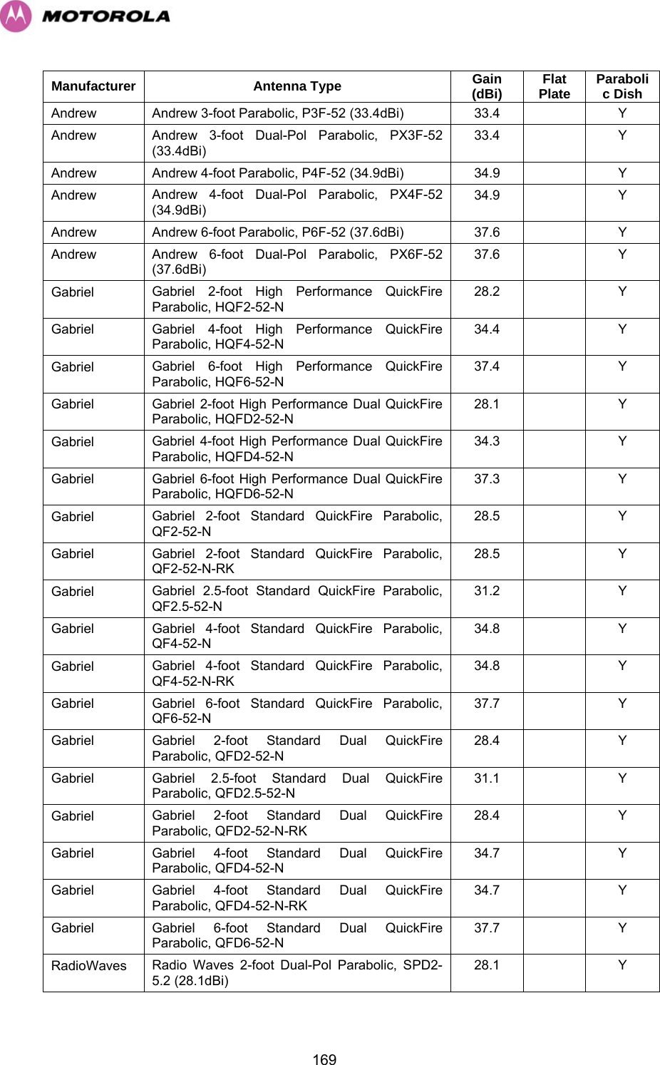
![54The length of the safety lanyard must not exceed 1m (approx 3 ft) in length. The lanyard should be made from a material that does not degrade in an outdoor environment. The safety lanyard must be fixed to a separate fixing point that is not part of the direct mounting system for the ODU. If the safety loop or its fixing is damaged in any way or has been exposed to a shock loading due to a fall it should be replaced with a new one before any further operations are undertaken. 7.7 Connecting Up 7.7.1 Preparing The Cable — RJ45 connections Cable can be purchased from your reseller or distributor in lengths up to 60m (197 feet). (Note that the maximum length between the PIDU Plus and ODU is 100m [330 feet].) Those wishing to source their own cables and connectors (see section H3.3.3 “Cables and Connectors” above) should follow the following instructions along with the cable and connector supplier’s instructions: Step 1: Assemble gland Step on cable as shown Step 2: Strip the outer insulation Step 3: Arrange conductors as shown in HFigure 19 and cut to length Step 4: Insert conductors and crimp](https://usermanual.wiki/Cambium-Networks/49XX/User-Guide-710871-Page-56.png)


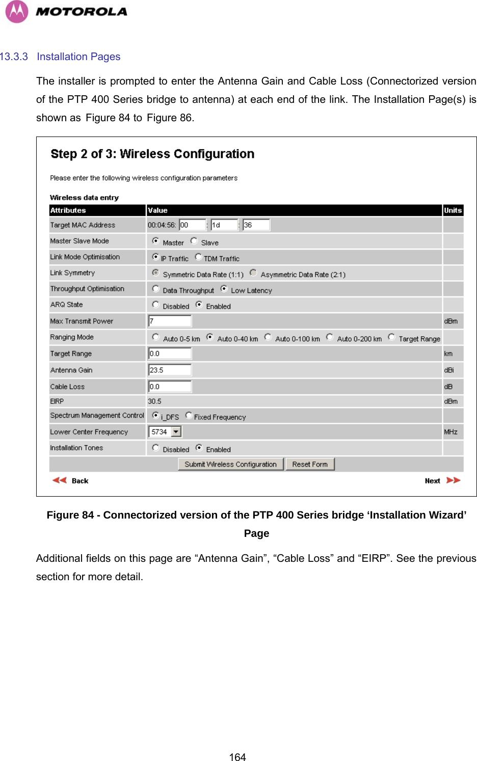
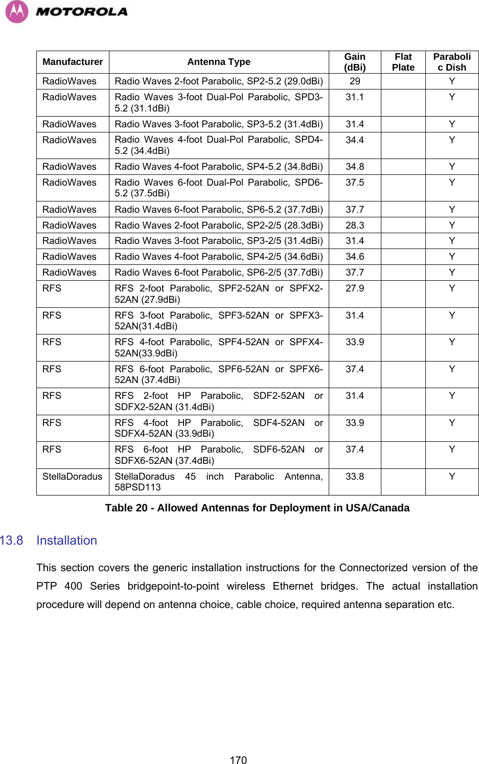
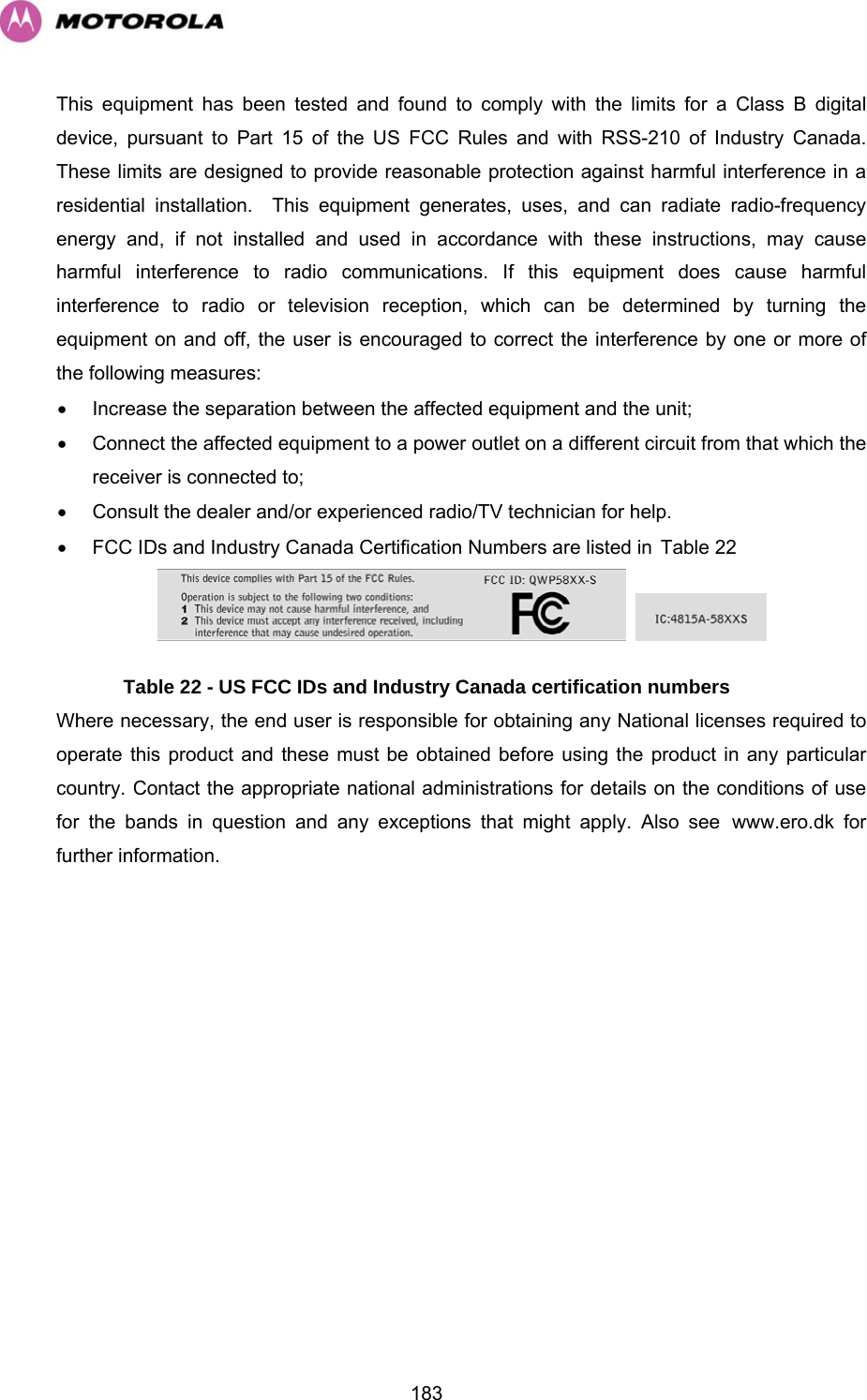


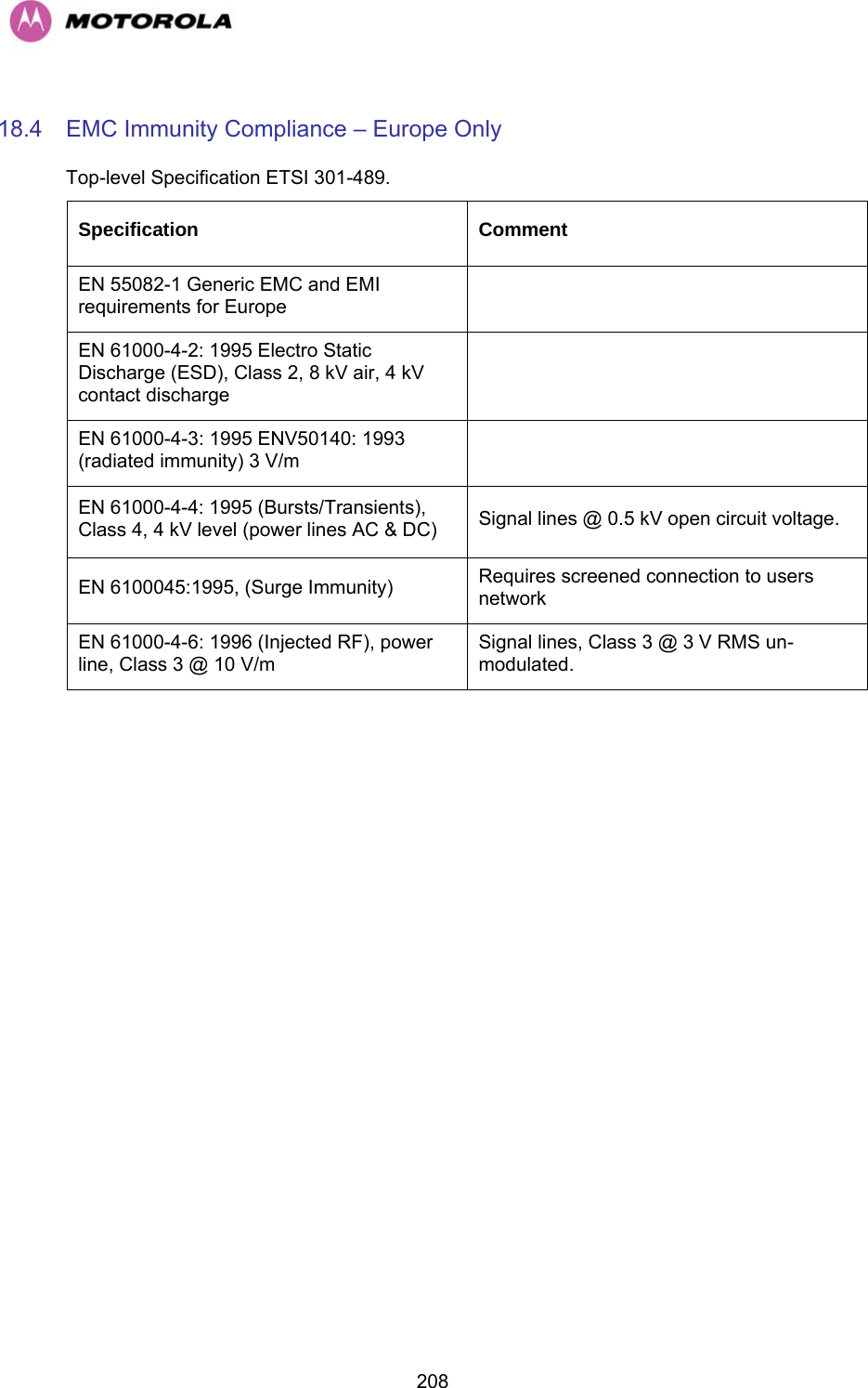
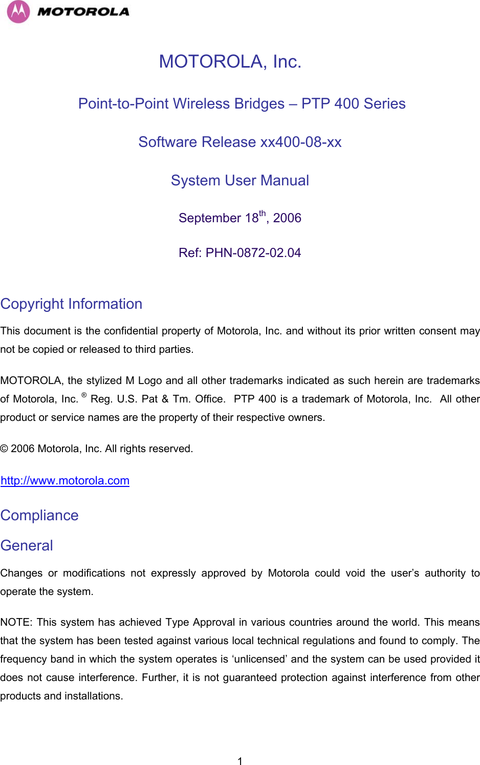
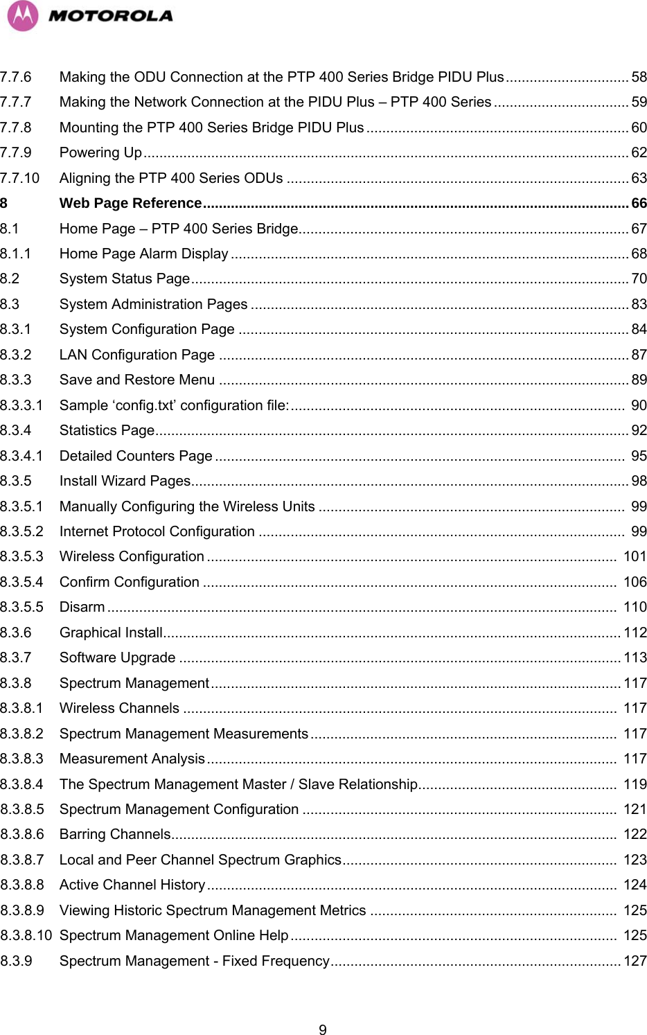
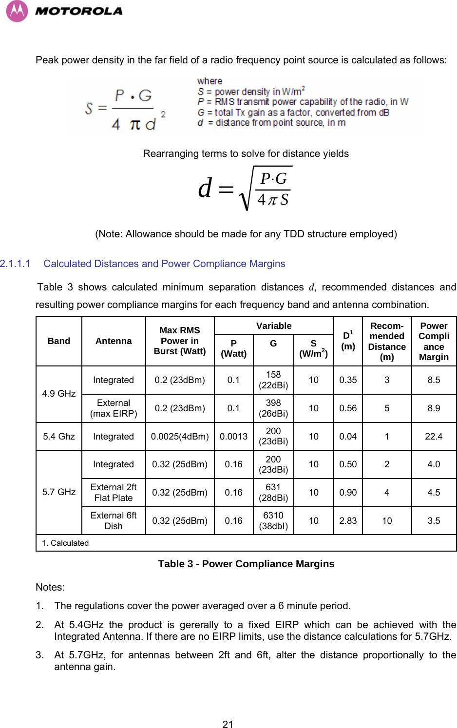
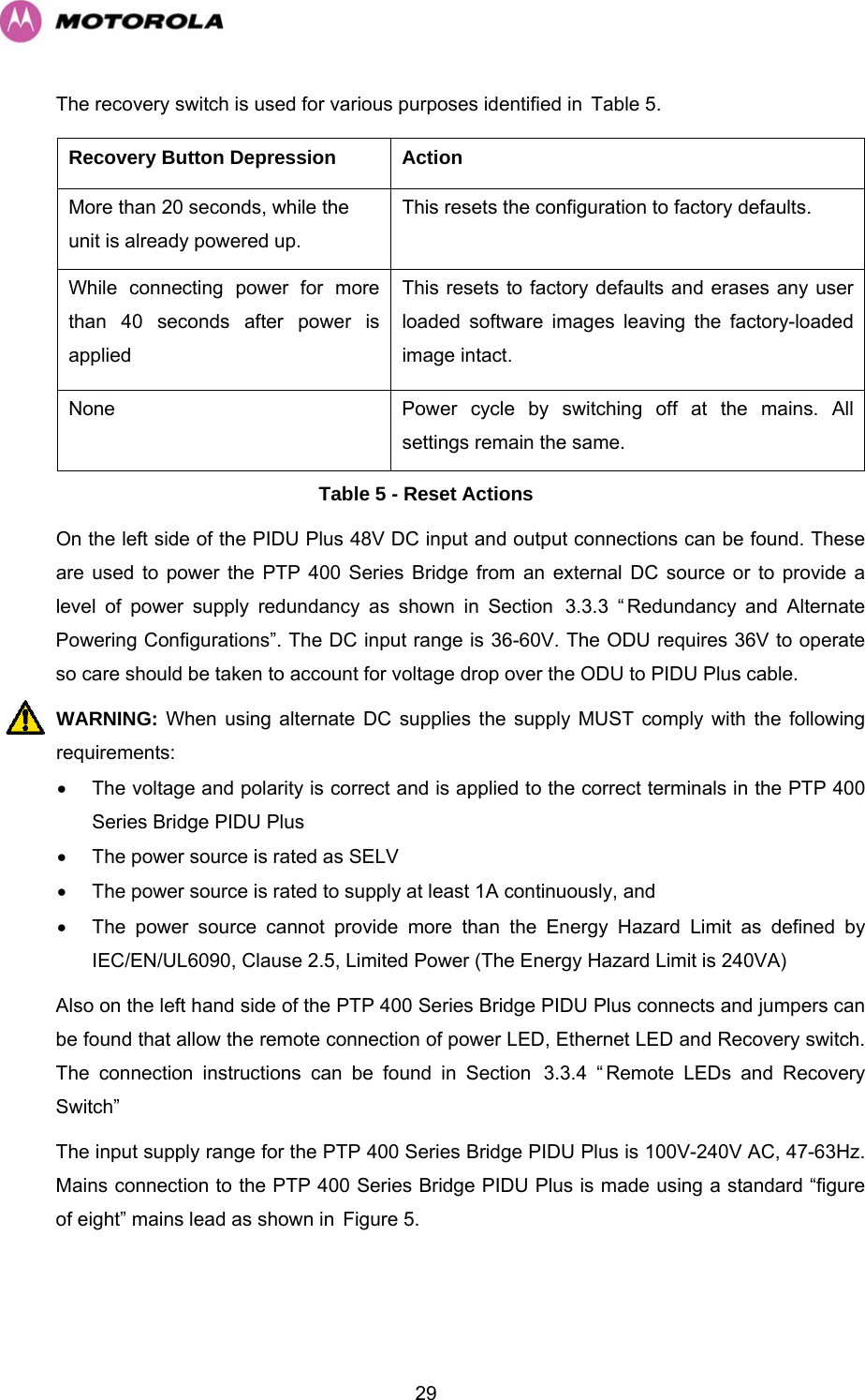
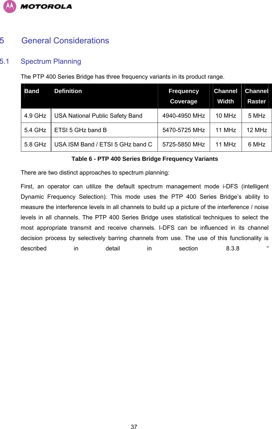
![20518.1.5 Ethernet Ethernet Bridging Protocol IEEE802.1; IEEE802.1p; IEEE802.3 compatible Interface 10/100BaseT (RJ-45), Supports MDI/MDIX Auto Crossover Single Direction Data Rate Mode 5.4 and 5.8 GHz 4.9 GHz 0 – 5 km Mode Data Rate Optimized Symmetric TDD (1:1) BPSK 1/2 QPSK 1/2 QPSK 2/3 16QAM 1/2 16QAM 3/4 64QAM 2/3 64QAM 3/4 64QAM 7/8 1.80 Mbps 4.05 Mbps 5.40 Mbps 8.10Mbps 12.15 Mbps 16.20 Mbps 18.22 Mbps 21.26 Mbps 1.35 Mbps 3.15 Mbps 4.20 Mbps 6.30 Mbps 9.44 Mbps 13.19 Mbps 14.84 Mbps 17.31 Mbps 0 – 5 km Mode Latency Optimized Symmetric TDD (1:1) BPSK 1/2 QPSK 1/2 QPSK 2/3 16QAM 1/2 16QAM 3/4 64QAM 2/3 64QAM 3/4 64QAM 7/8 1.68 Mbps 3.78 Mbps 5.04 Mbps 7.55 Mbps 11.23 Mbps 15.11 Mbps 17.00 Mbps 19.83 Mbps Not Applicable 0 – 5 km Mode Data Rate Optimized Asymmetric TDD (2:1) BPSK 1/2 QPSK 1/2 QPSK 2/3 16QAM 1/2 16QAM 3/4 64QAM 2/3 64QAM 3/4 64QAM 7/8 2.34 Mbps 5.27 Mbps 7.03 Mbps 10.54 Mbps 15.82 Mbps 21.09 Mbps 23.72 Mbps 27.68 Mbps 1.76 Mbps 4.10 Mbps 5.46 Mbps 8.2 Mbps 12.29 Mbps 17.17 Mbps 19.32 Mbps 22.54 Mbps Other Range Modes Data Rate Optimized Symmetric TDD (1:1) 0 – 40 km [0-25 miles] Rate reduces by 7.2% 0 – 100 km [0-62 miles] Rate reduces by 17.3% 0 – 200 km [0-124 miles] Rate reduces by 30% Other Range Modes Latency Optimized Symmetric TDD (1:1) 0 – 40 km [0-25 miles] Rate reduces by 12.5% 0 – 100 km [0-62 miles] Rate reduces by 28% 0 – 200 km [0-124 miles] Rate reduces by 44.4% Other Range Modes Data Rate Optimized Asymmetric TDD (2:1) 0 – 40 km [0-25 miles] Rate reduces by 9.1% 0 – 100 km [0-62 miles] Rate reduces by 21.4% 0 – 200 km [0-124 miles] Rate reduces by 35.8%](https://usermanual.wiki/Cambium-Networks/49XX/User-Guide-710871-Page-207.png)