Cambium Networks 58250 PTP250 Point to Point Broadband Wireless System User Manual PTP 250 User Guide
Cambium Networks Limited PTP250 Point to Point Broadband Wireless System PTP 250 User Guide
UserManual.wiki
>
Cambium Networks
>
58250 User Manual
user manual
Navigation menu
Upload a User Manual
Namespaces
Wiki Guide
HTML
PDF
Info
Views
User Manual
Discussion / Help
Navigation


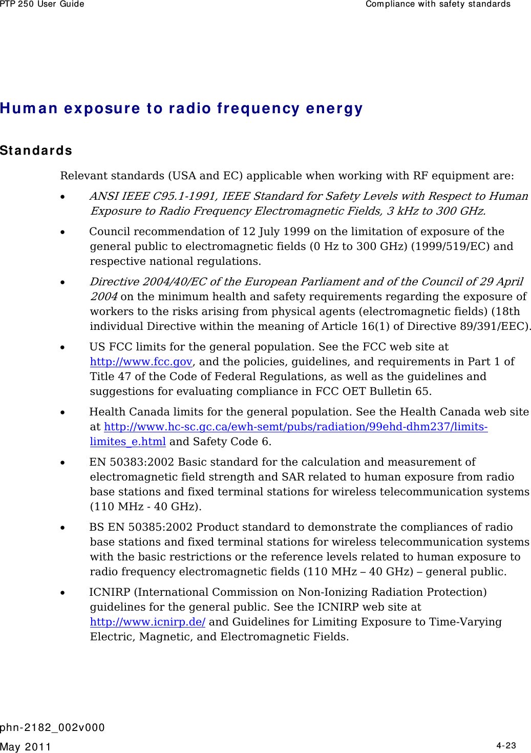


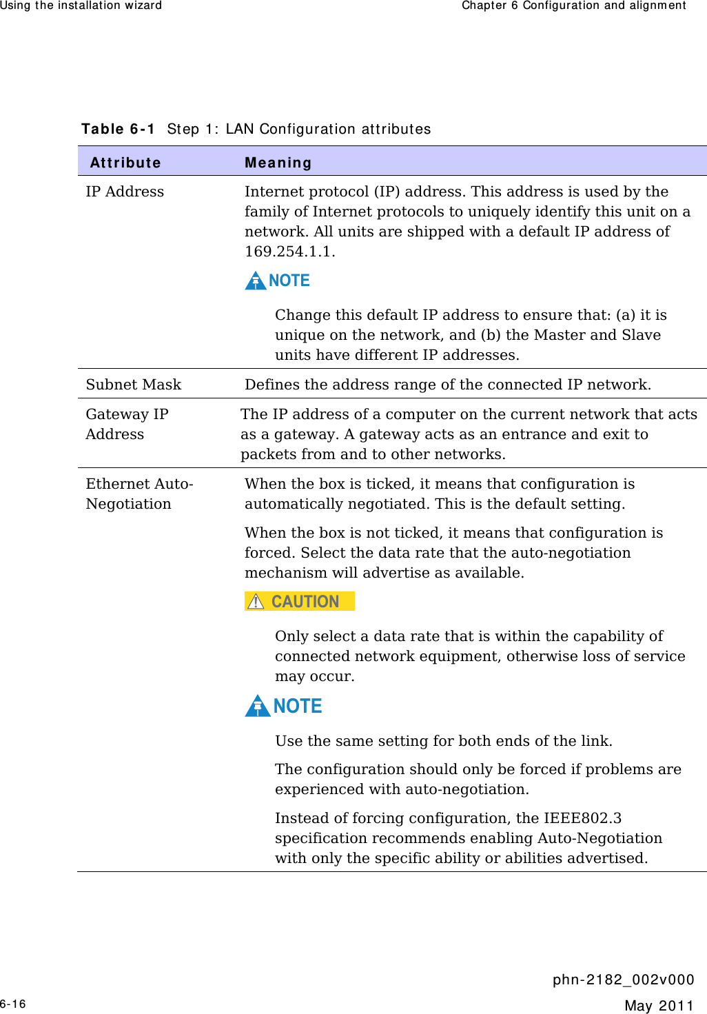
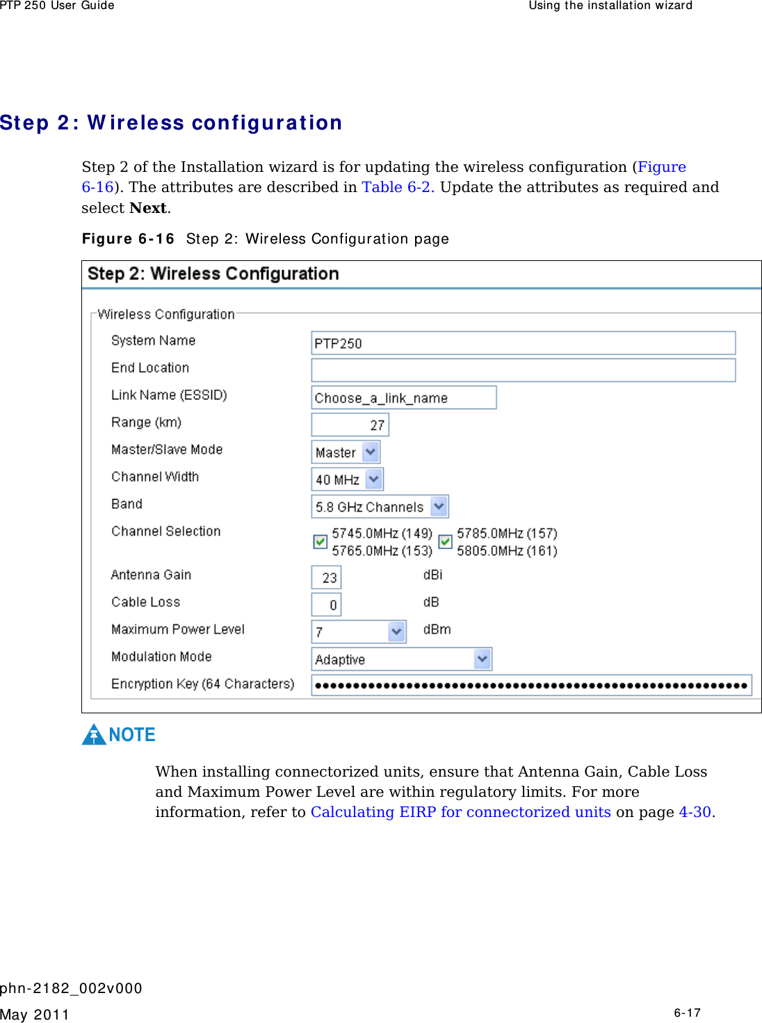
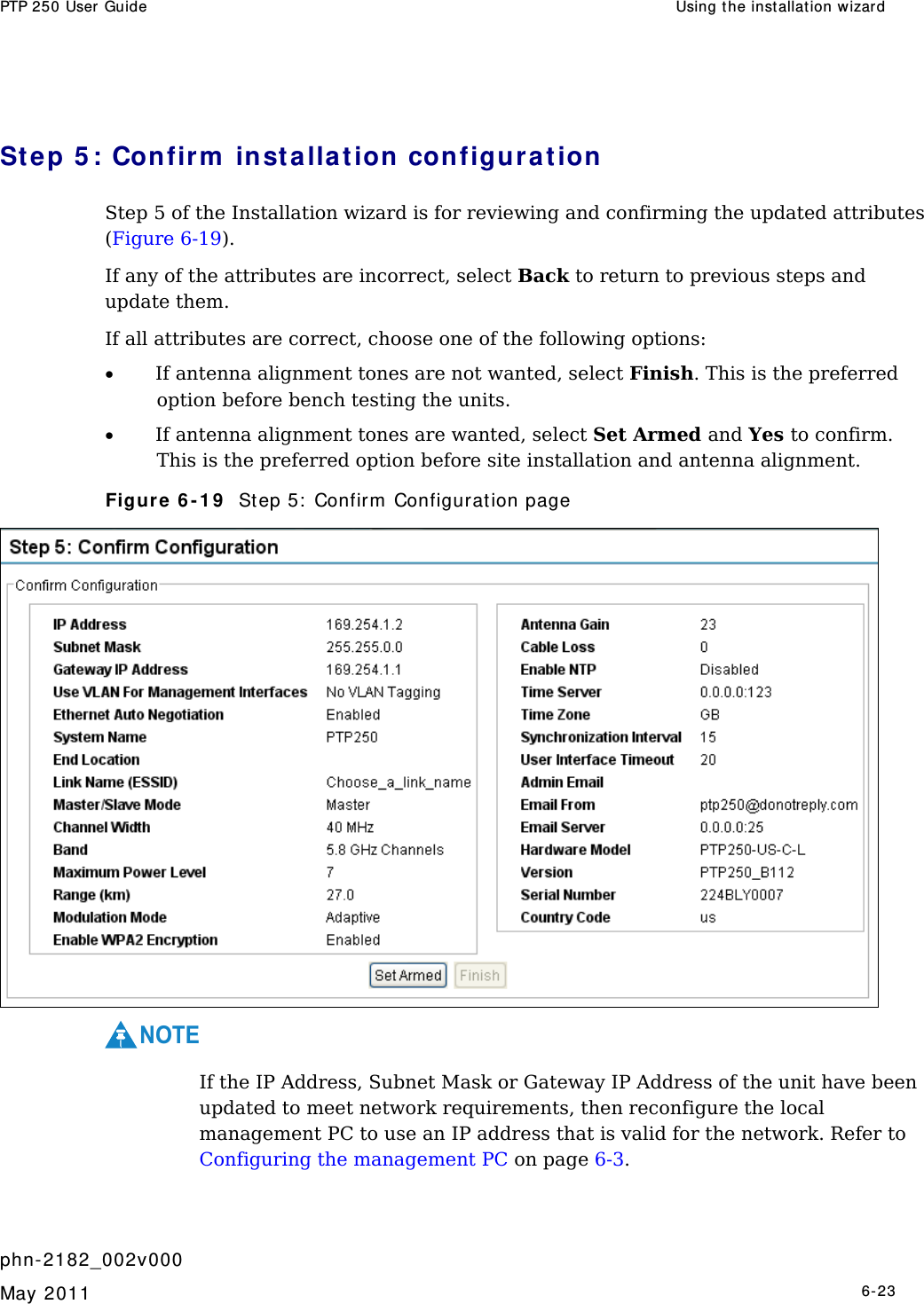
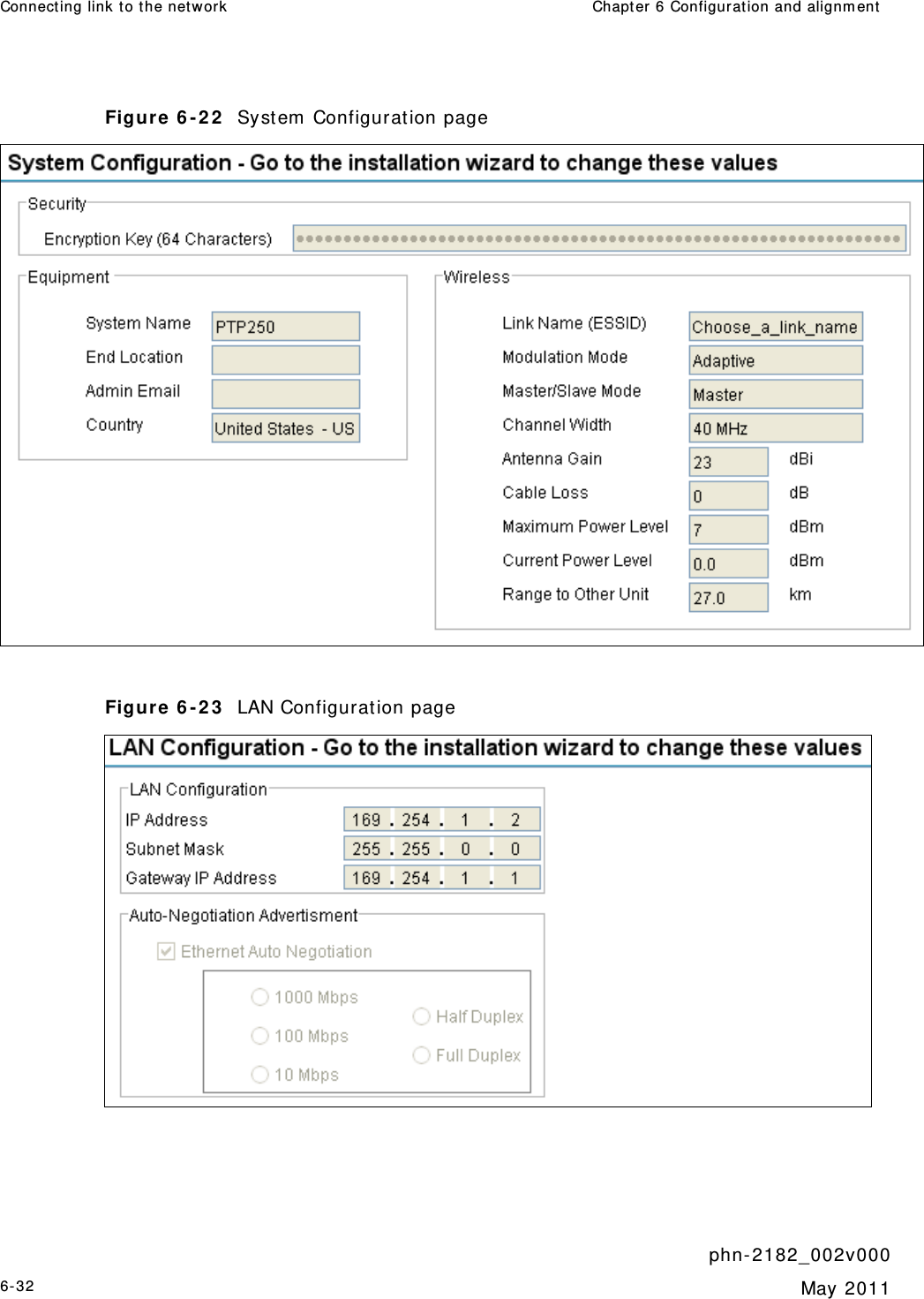
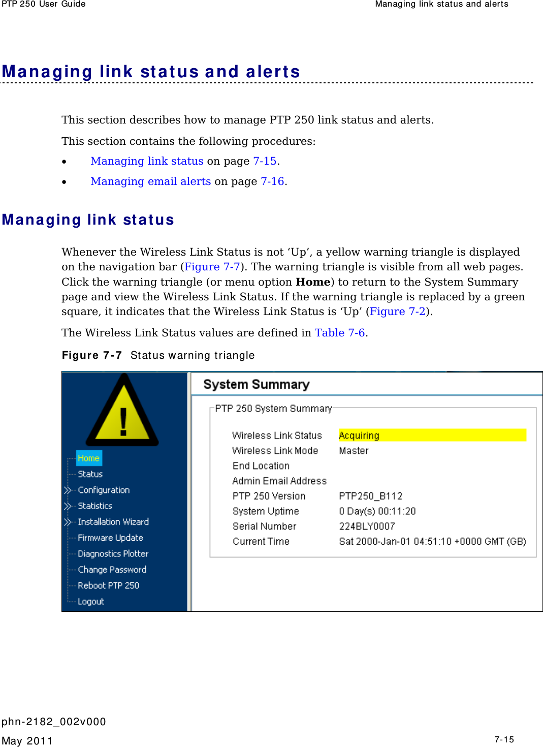
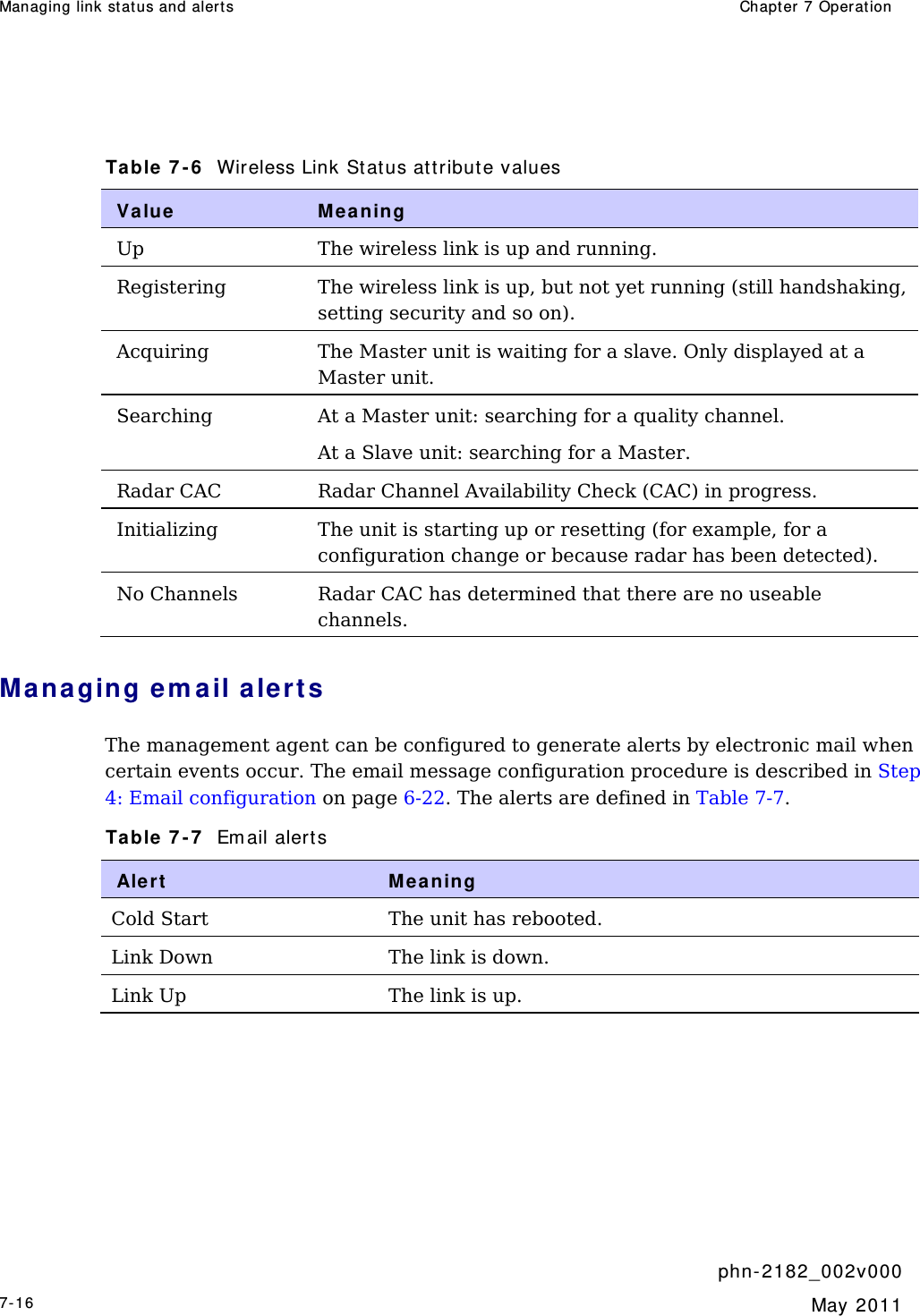
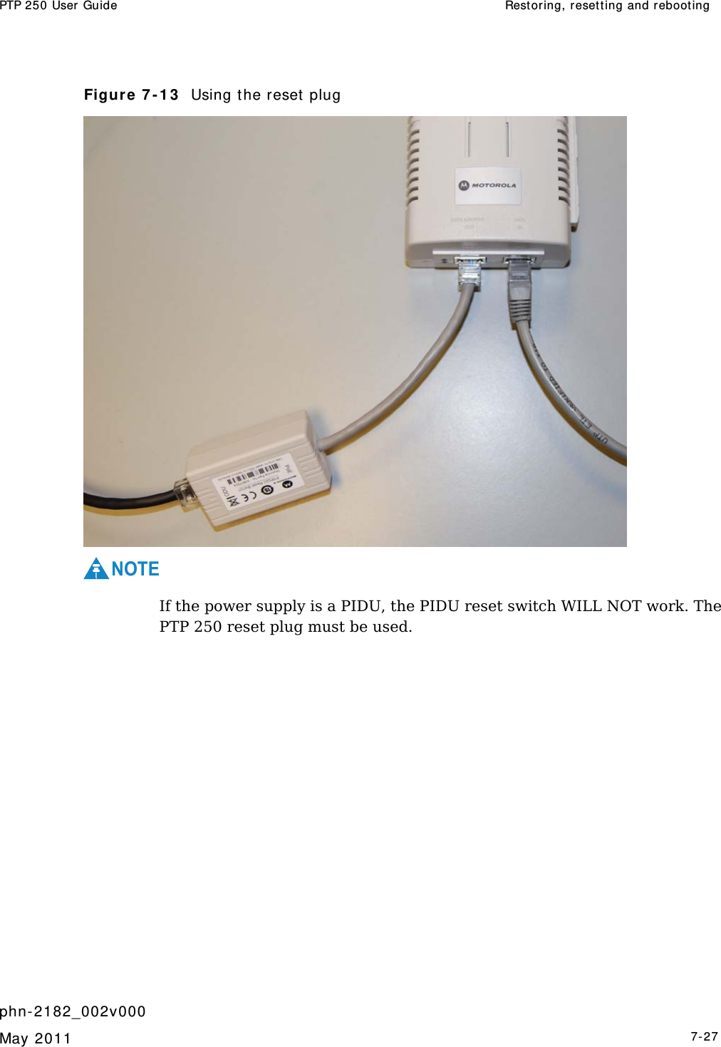
![Using the inst allation wizar d Chapt er 6 Configuration and alignm ent phn- 2 182_002v 000 6-18 May 2011 Table 6 - 2 St ep 2: Wireless Configurat ion att ribut es Att r ibute Me aning System Name A name for the link. Spaces are not allowed, so use underscores instead. End Location The location of the link end. Spaces are not allowed, so use underscores instead. Link Name (ESSID) A link can only be established between units that have identical Link Names. Link Name may consist of letters (A-Z and a-z), numbers (0-9) and the following special characters (no spaces): (),-.,:<=>[]_{} Range (km) The link range. The value must not be less than the actual distance between the link ends. Master/Slave Mode Each link consists of one ‘Master’ and one ‘Slave’ unit. The Master is used to control and maintain the point-to-point link. The Master transmits until the link is made, while the Slave listens for its Master and only transmits when the Master has been identified. As all units are shipped with a default setting of ‘Slave’, one unit in the link must be reset to ‘Master’. Channel Width Width (MHz) of the radio channel used by this link. The selection depends upon the frequency variant and country of operation. This can only be updated at the Master unit. Band The frequency band (GHz) in which this link operates. This can only be updated at the Master unit. Channel Selection The channel (MHz) in which this link operates. This can only be updated at the Master unit. If Channel Width is set to 40 MHz, then each tick box selects two 20 MHz channels: the first is Current Channel and the second is Extended Channel. Antenna Gain Gain (dBi) of the antenna that is connected to this unit. See Antenna specifications on page 4-14.](https://usermanual.wiki/Cambium-Networks/58250/User-Guide-1459732-Page-174.png)