Cambium Networks 58500 Wireless Ethernet Bridge User Manual PTP 500 Series User Guide
Cambium Networks Limited Wireless Ethernet Bridge PTP 500 Series User Guide
UserManual.wiki
>
Cambium Networks
>
58500 User Manual
>
Manual
Contents
1.
Users Manual
2.
Manual
3.
User Guide
Manual
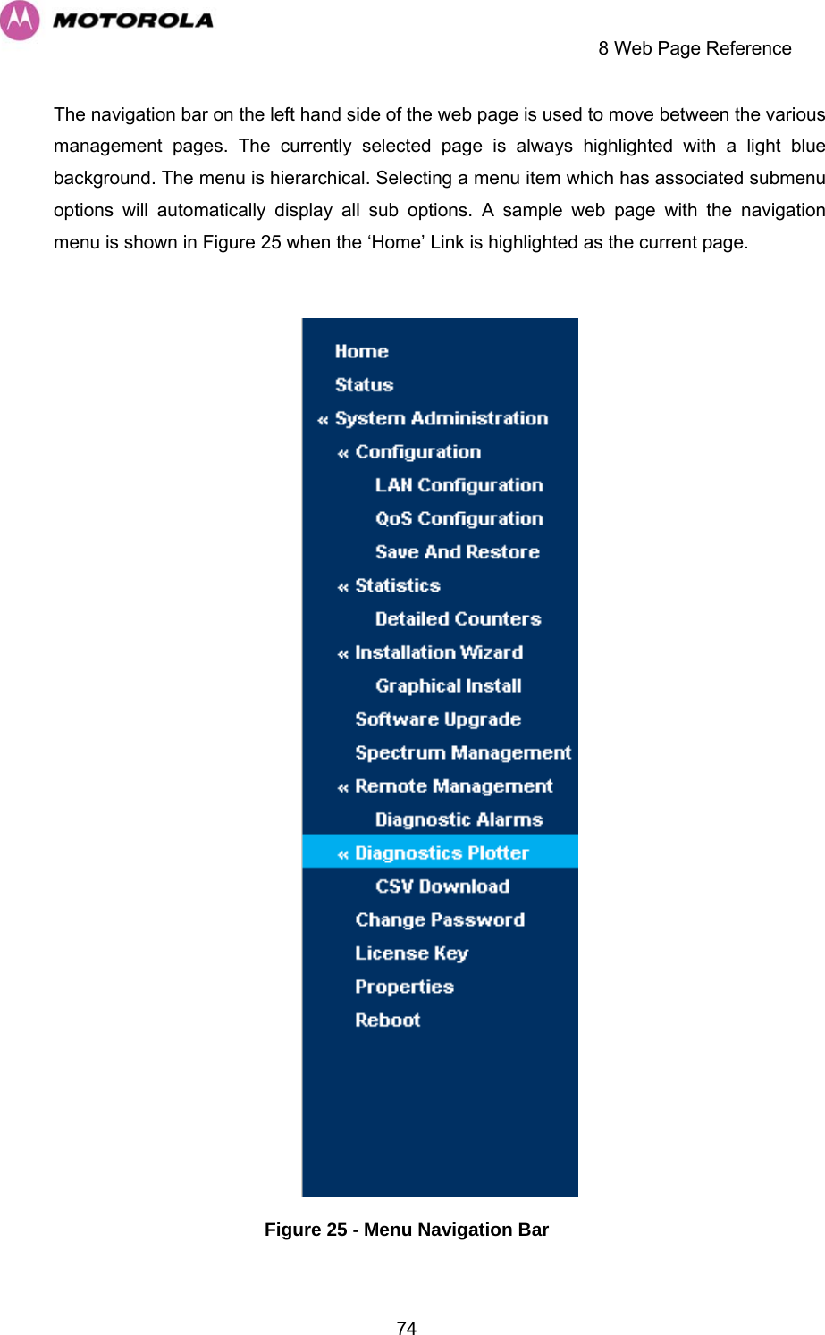
Navigation menu
Upload a User Manual
Namespaces
Wiki Guide
HTML
PDF
Info
Views
User Manual
Discussion / Help
Navigation
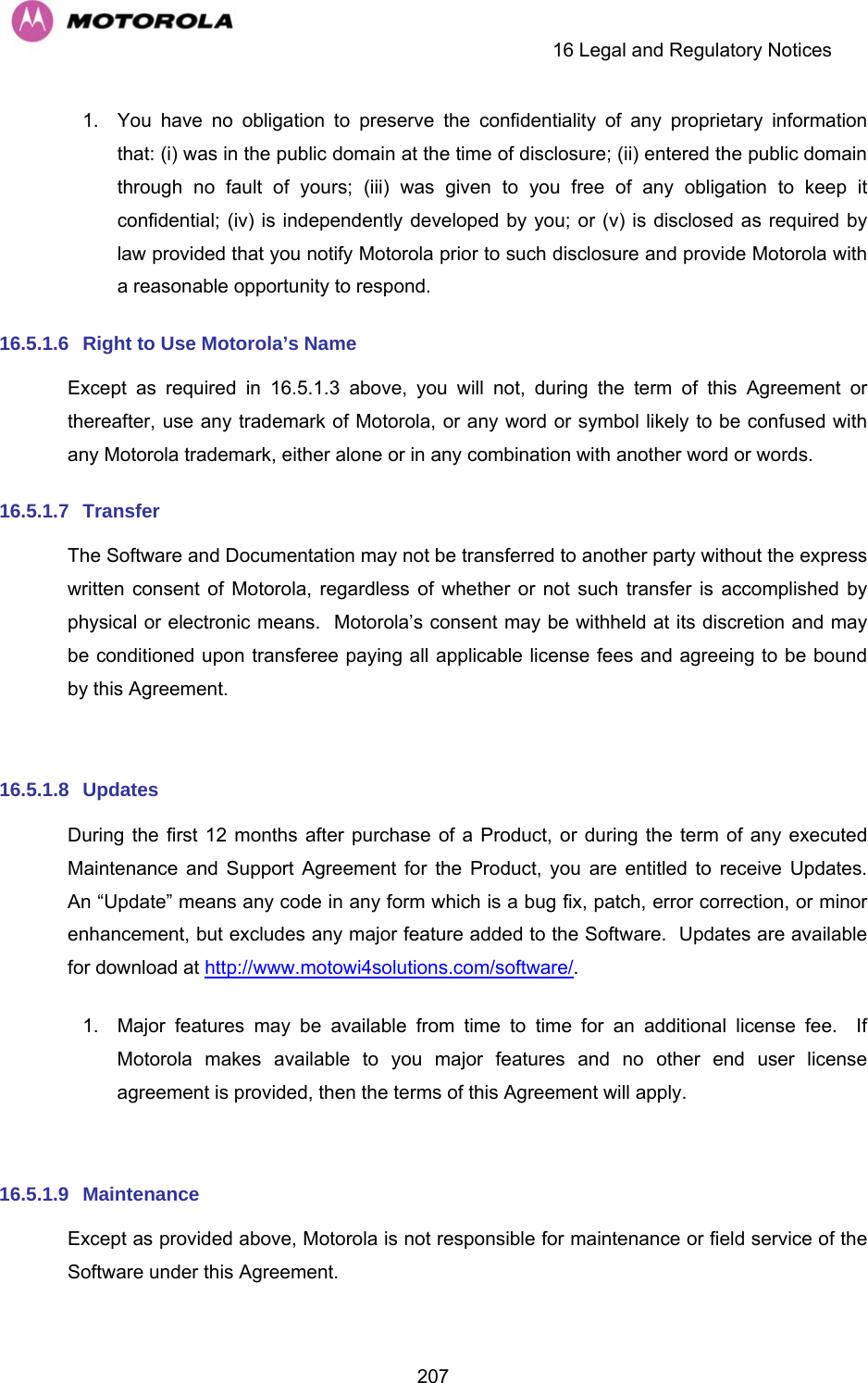
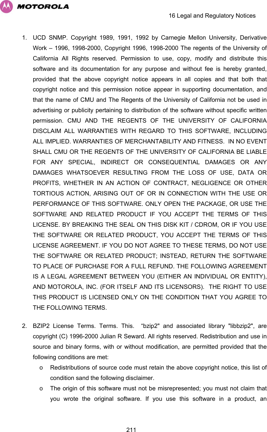
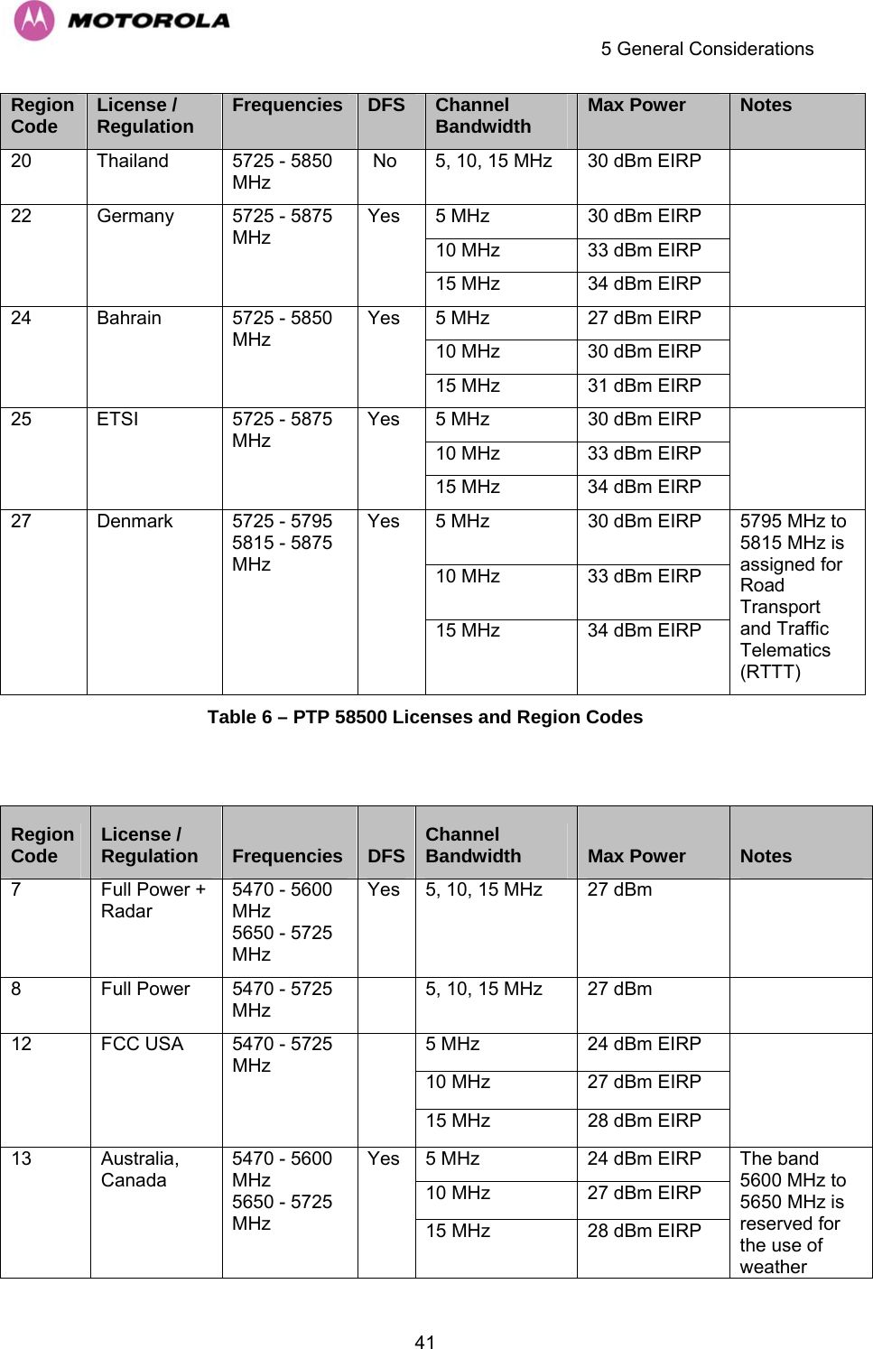
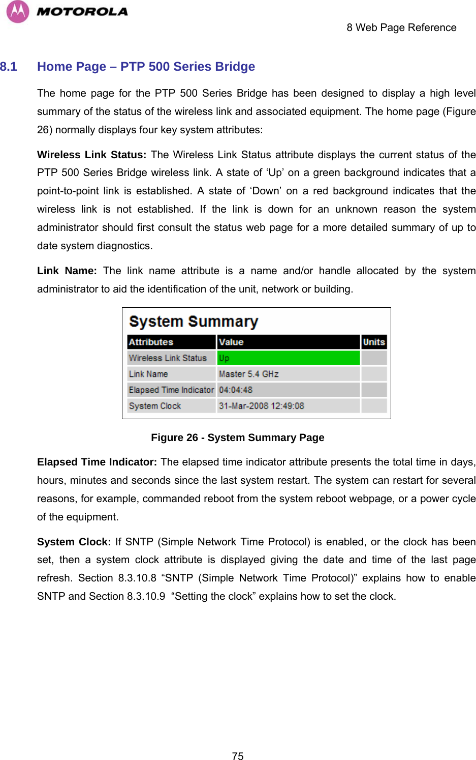
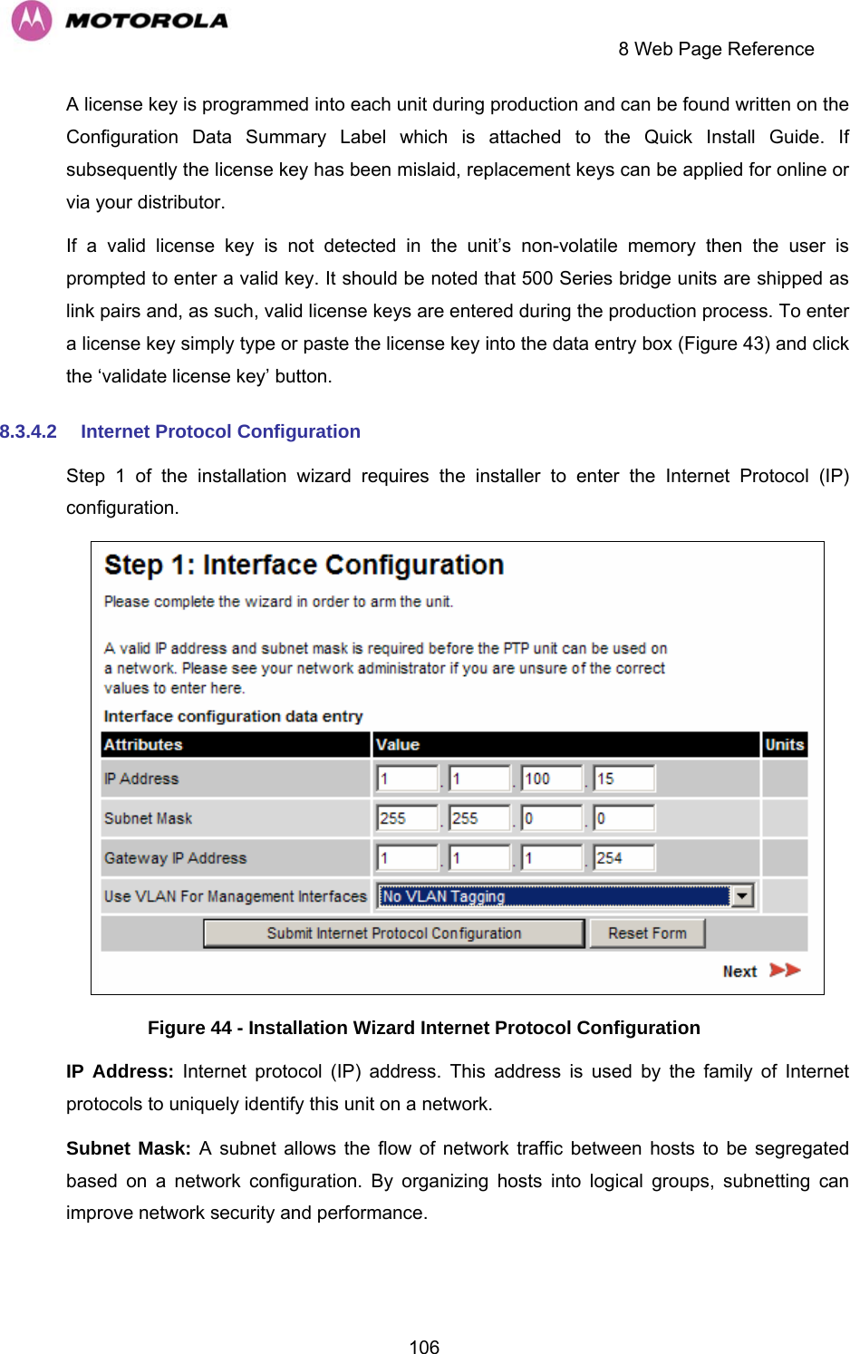
![3Regulations applicable to PTP 54500 variant Examples of Regulatory Limits at 5.4GHz FCC Under FCC Regulations, operation of this product is only allowed with a License Key for Region 12. This implements Radar Detection in accordance with FCC Regulations and limits the EIRP to the regulatory limits below: EIRP ≤ Max of [(17 +10 x Log(Channel BW)) and 30]dBm ETSI Under ETSI Regulations, operation of this product is only allowed with a License Key for Region 26. This implements Radar Detection in accordance with ETSI Regulations, including barring of the band from 5600MHz to 5650MHz and limits the EIRP to the regulatory limits below: EIRP ≤ Max of [(17 +10 x Log(Channel BW)) and 30]dBm Canada Under Industry Canada Regulations, operation of this product is only allowed with a License Key for Region 13. This implements Radar Detection in accordance with Canadian Regulations, including barring of the band from 5600MHz to 5650MHz and limits the EIRP to the regulatory limits below: EIRP ≤ Max of [(17 +10 x Log(Channel BW)) and 30]dBm General Notice Applicable to Europe This equipment complies with the essential requirements for the EU R&E Directive 1999/5/EC. NOTE: In regions other than EU/USA, specific local regulations may apply. It is the responsibility of the installer/user to check that the equipment as deployed meets local regulatory requirements.](https://usermanual.wiki/Cambium-Networks/58500.Manual/User-Guide-992908-Page-5.png)
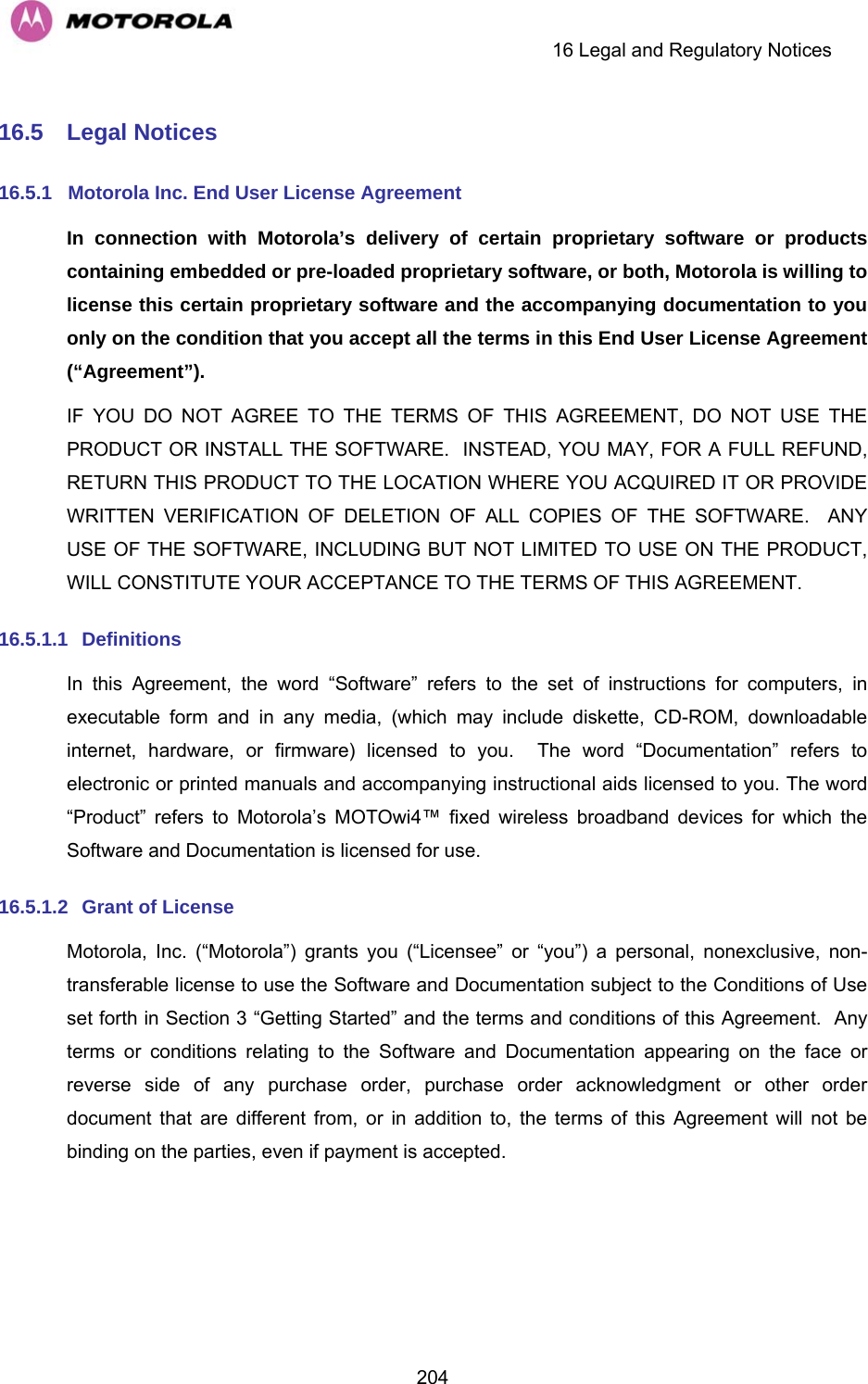
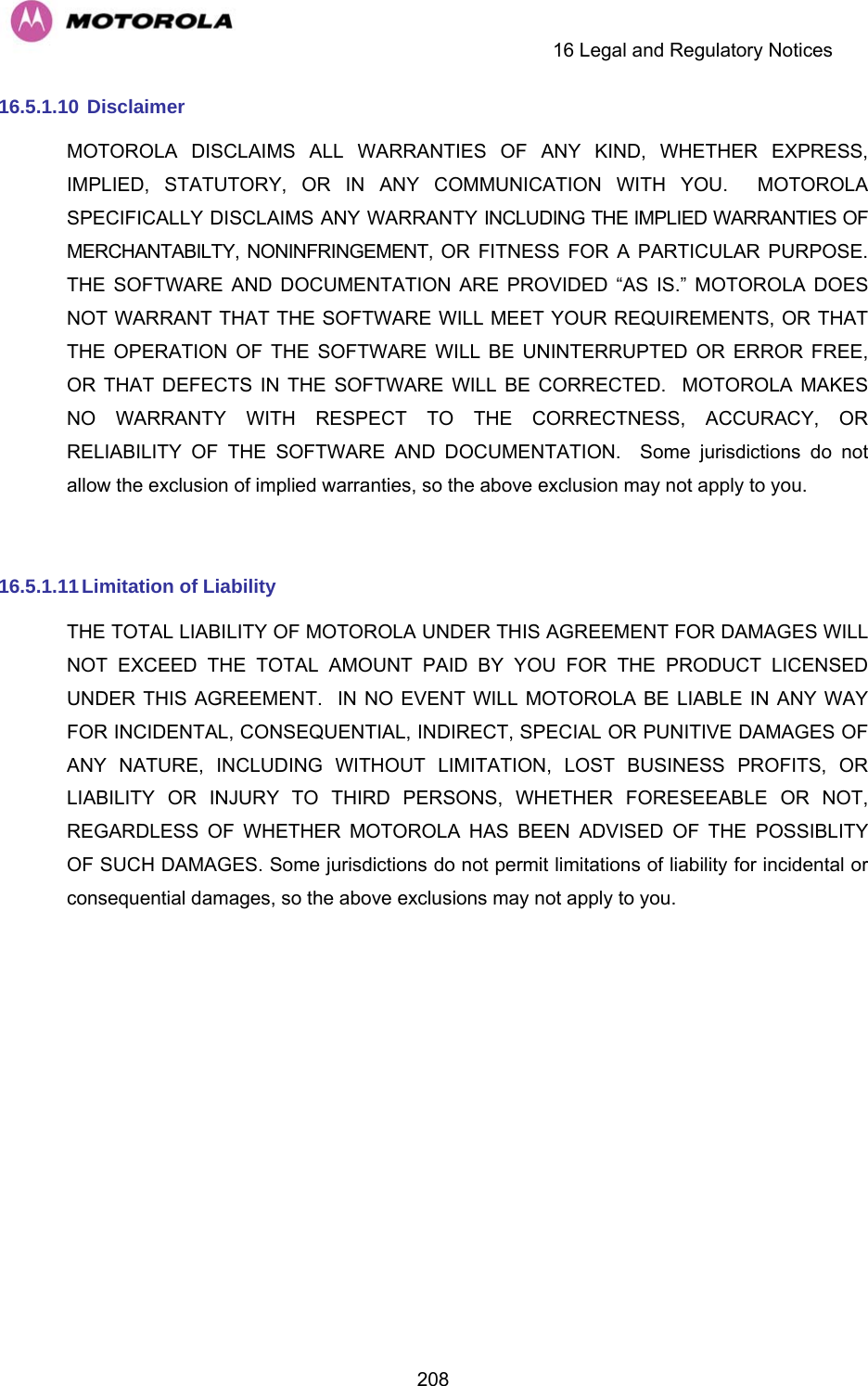
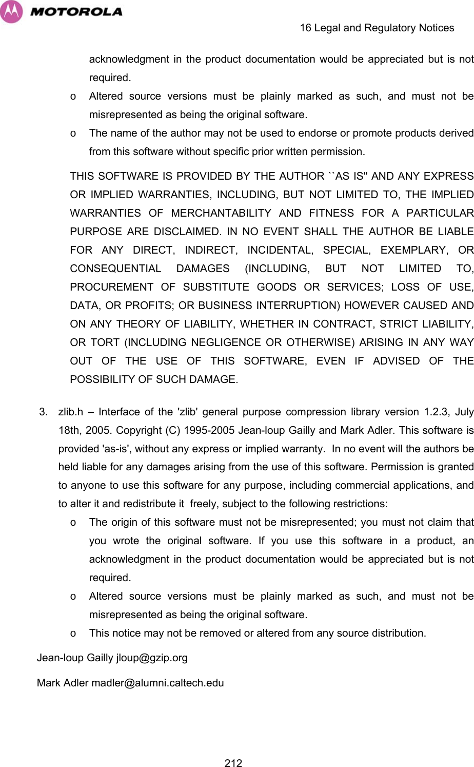
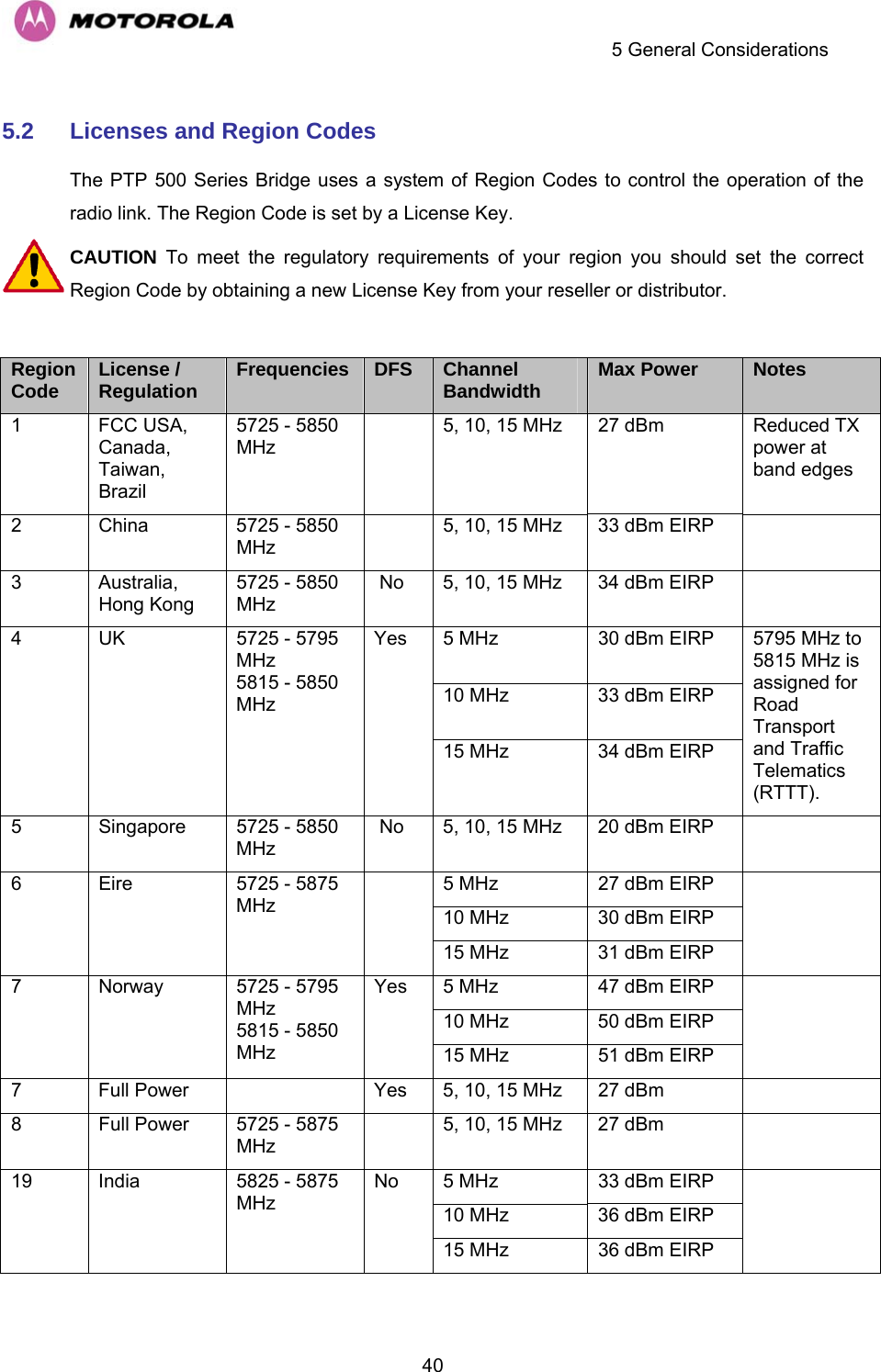
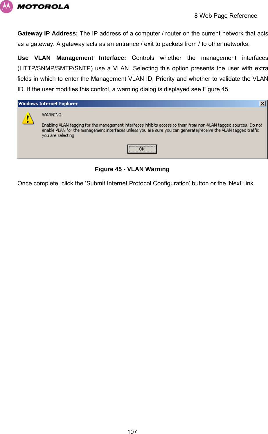
![4Regulations applicable to PTP 58500 variant Examples of Regulatory Limits USA/ Canada/ Taiwan Equipment can be operated in any mode, best results will be obtained using Region 1 settings UK Under UK Regulations, operation of this product is allowed with a License Key for Region 4 . This implements Radar Detection with barring of the band from 5795MHz to 5815MHz and above 5850MHz. It limits the EIRP to the Regulatory Limits below: EIRP ≤ Max of [(23 +10 x Log(Channel BW)) and 36]dBm Eire Under Eire Regulations, operation of this product is only allowed with a License Key for Region 6. This implements Radar Detection and limits the EIRP to the Regulatory Limits below: EIRP ≤ Max of [(20 +10 x Log(Channel BW)) and 33]dBm Norway Under Norway Regulations, operation of this product is only allowed with a License Key for Region 7. This limits the EIRP to the Regulatory Limits below: EIRP ≤ Max of [(40 +10 x Log(Channel BW)) and 53]dBm Germany Operation of this product is only allowed with a License Key for Region 22 This limits the band of operation to 5755MHz to 5875MHz and limits the EIRP to the Regulatory Limits below: EIRP ≤ Max of [(23 +10 x Log(Channel BW)) and 36]dBm Denmark Operation of this product is only allowed with a License Key for Region 27 . This implements Radar Detection with barring of the band from 5795MHz to 5815MHz. It limits the EIRP to the Regulatory Limits below: EIRP ≤ Max of [(23 +10 x Log(Channel BW)) and 36]dBm General Notice Applicable to Europe This equipment complies with the essential requirements for the EU R&E Directive 1999/5/EC. The use of 5.8GHz for Point to Point radio links is not harmonized across the EU. However, the regulatory situation in Europe is changing and the radio spectrum may become available in other countries in the near future. Please contact Motorola for the latest situation.](https://usermanual.wiki/Cambium-Networks/58500.Manual/User-Guide-992908-Page-6.png)
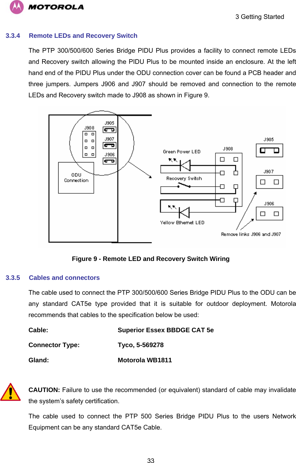

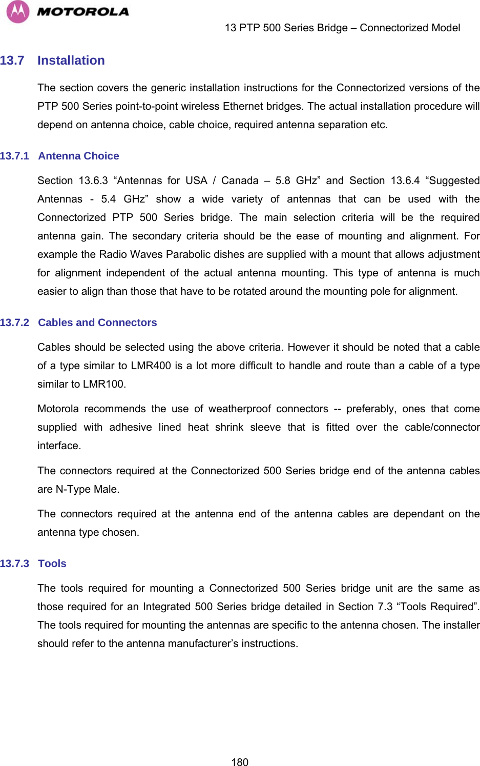
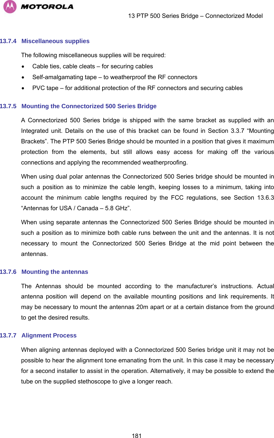
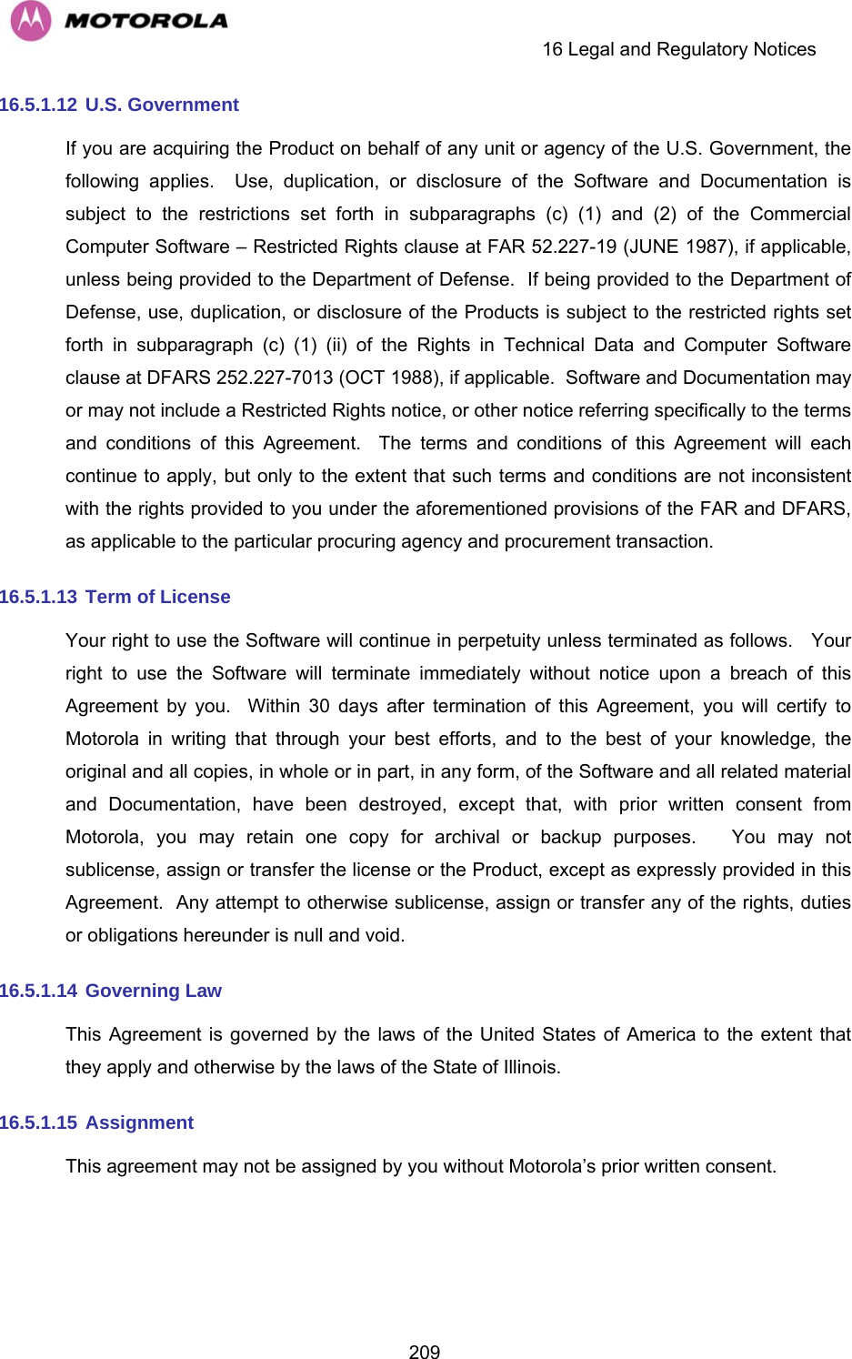
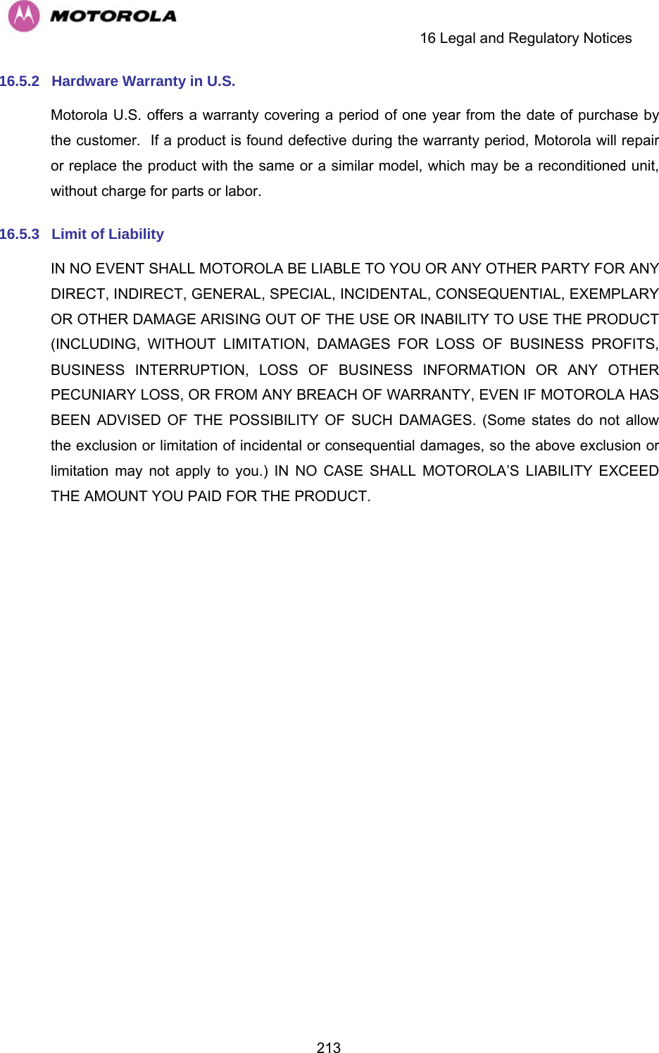
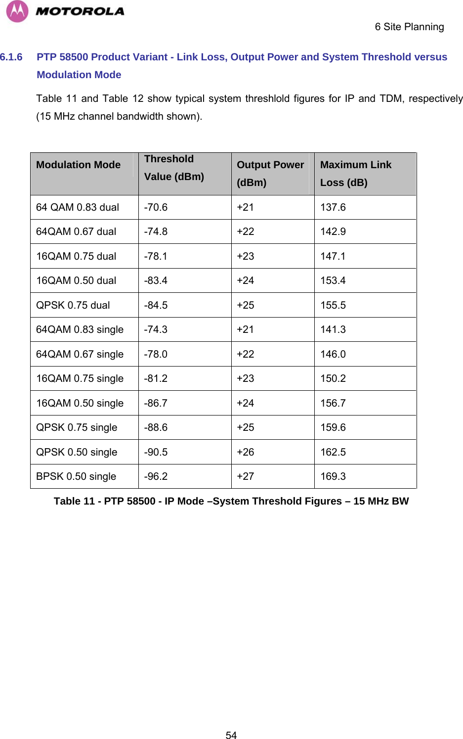
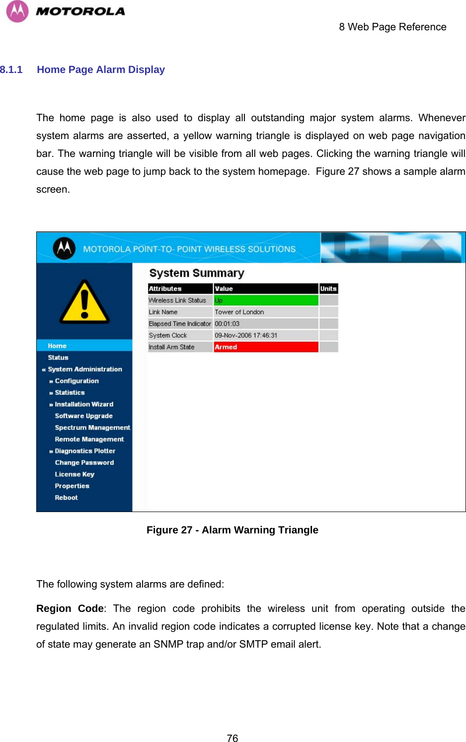
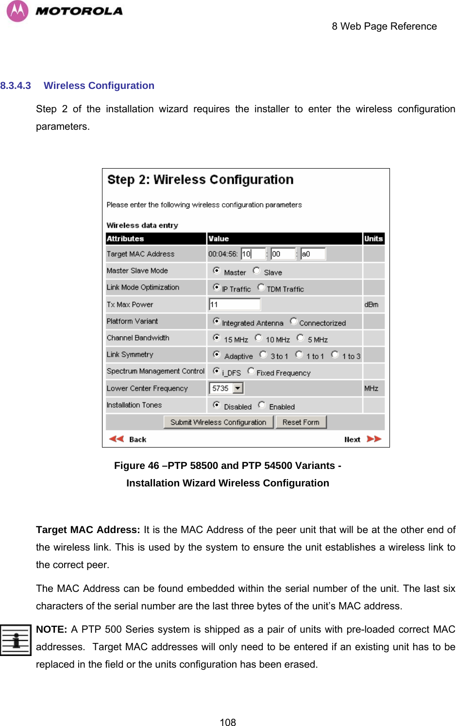
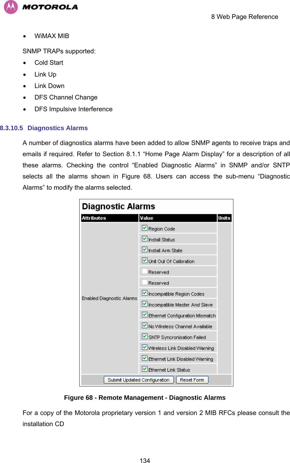
![6 Site Planning 496 Site Planning 6.1 Site Selection Criteria The following are guidelines for selecting the installation location of the ODU and PIDU Plus for a PTP 500 Series Bridge. 6.1.1 ODU Site Selection When selecting a site for the ODU the following should be taken into consideration: • It is not possible for people to stand or walk inadvertently in front of the antenna • Height and location to achieve the best radio path • Height in relation to other objects with regard to lightning strikes • As high as practically possible over obstructions • Point it at the Remote end • Aesthetics and planning permission issues • Distance from the ODU and connected Network equipment (Maximum cable run from the ODU to the connected equipment is 100m [330 ft]) 6.1.2 PTP 500 Series Bridge PIDU Plus Site Selection When selecting a site for the PIDU Plus the following should be taken into consideration: • Availability of a mains electricity supply • Accessibility for viewing status indicators and pressing Recovery switch.](https://usermanual.wiki/Cambium-Networks/58500.Manual/User-Guide-992908-Page-51.png)

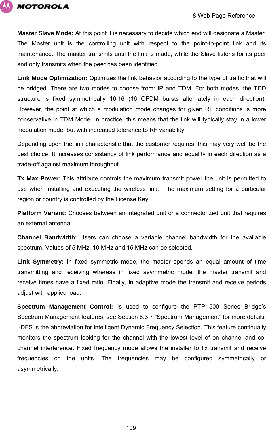
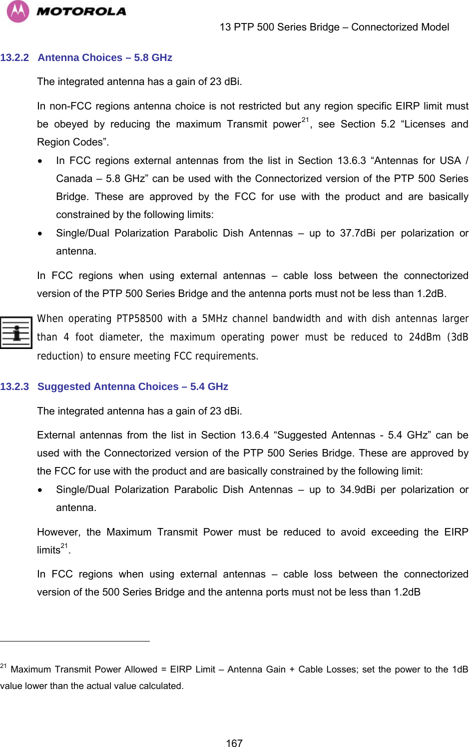
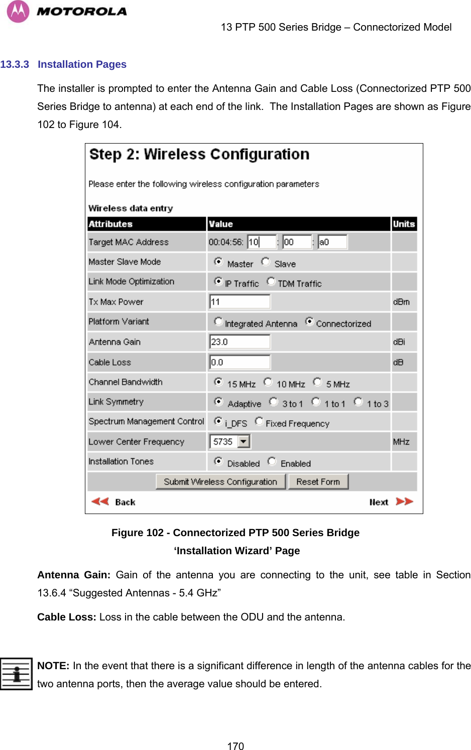
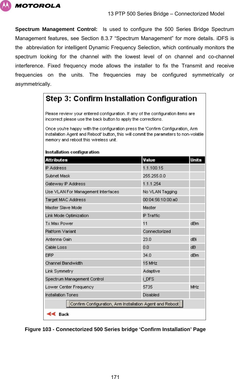
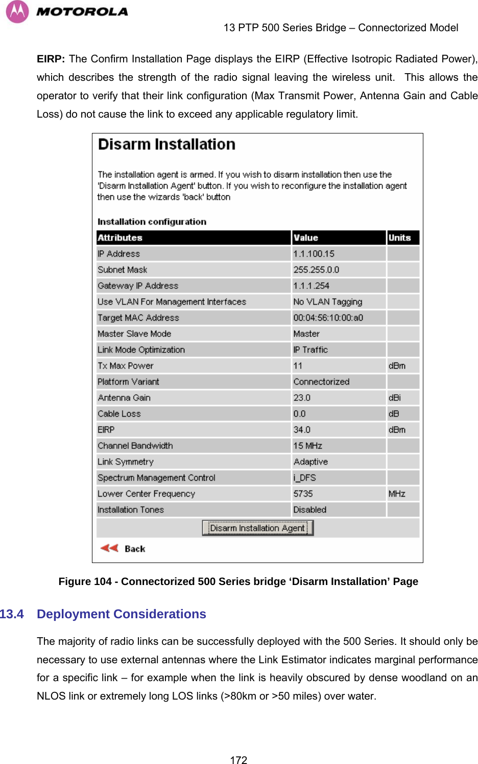
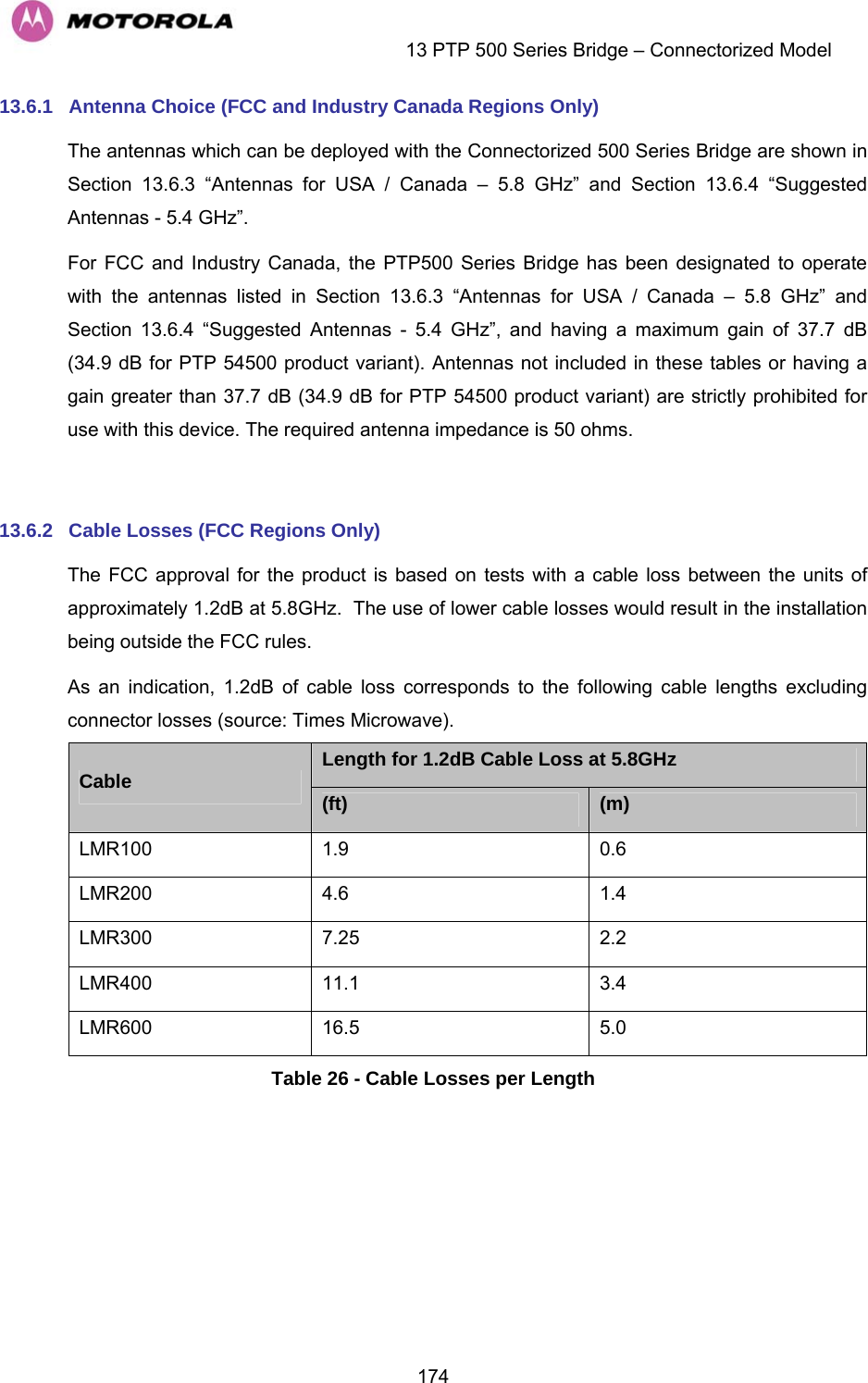
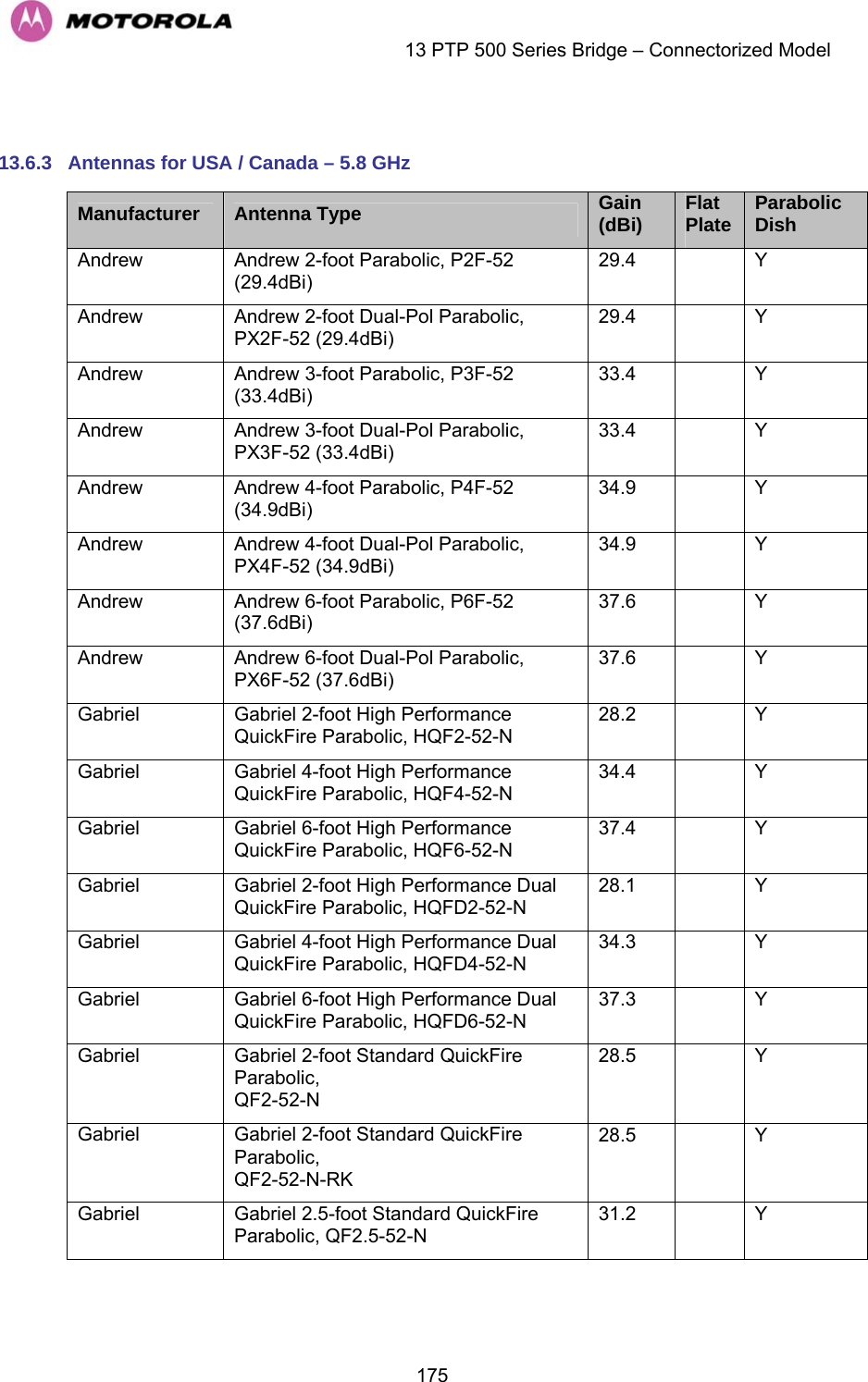
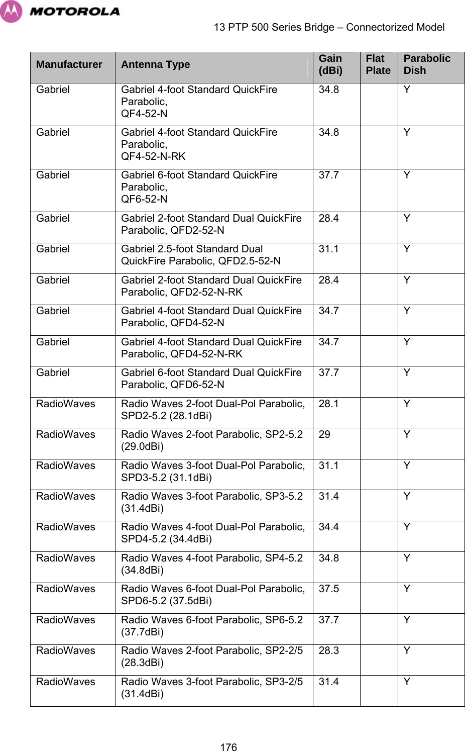
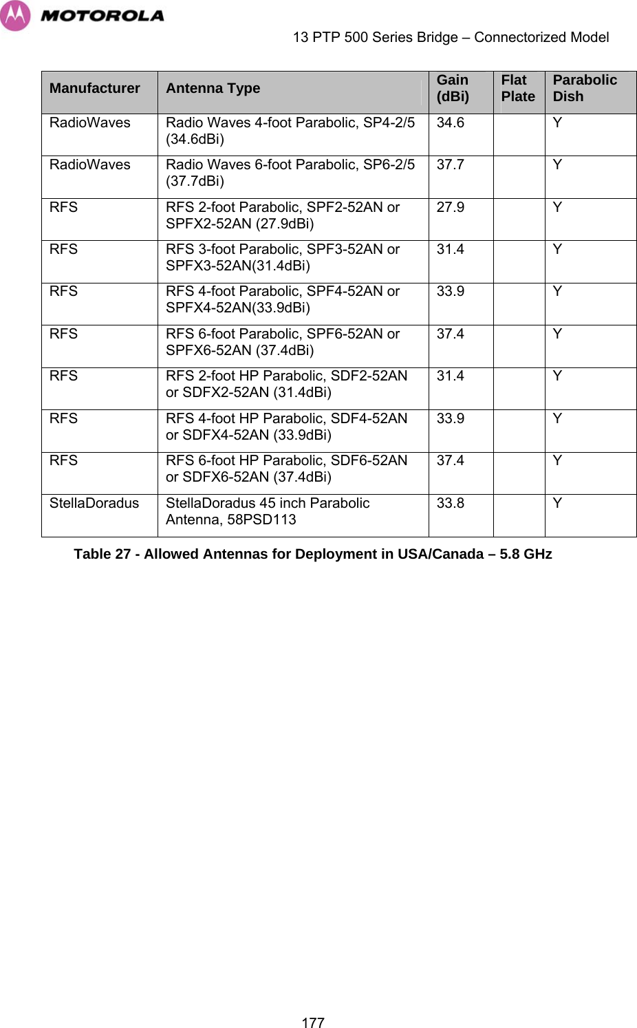
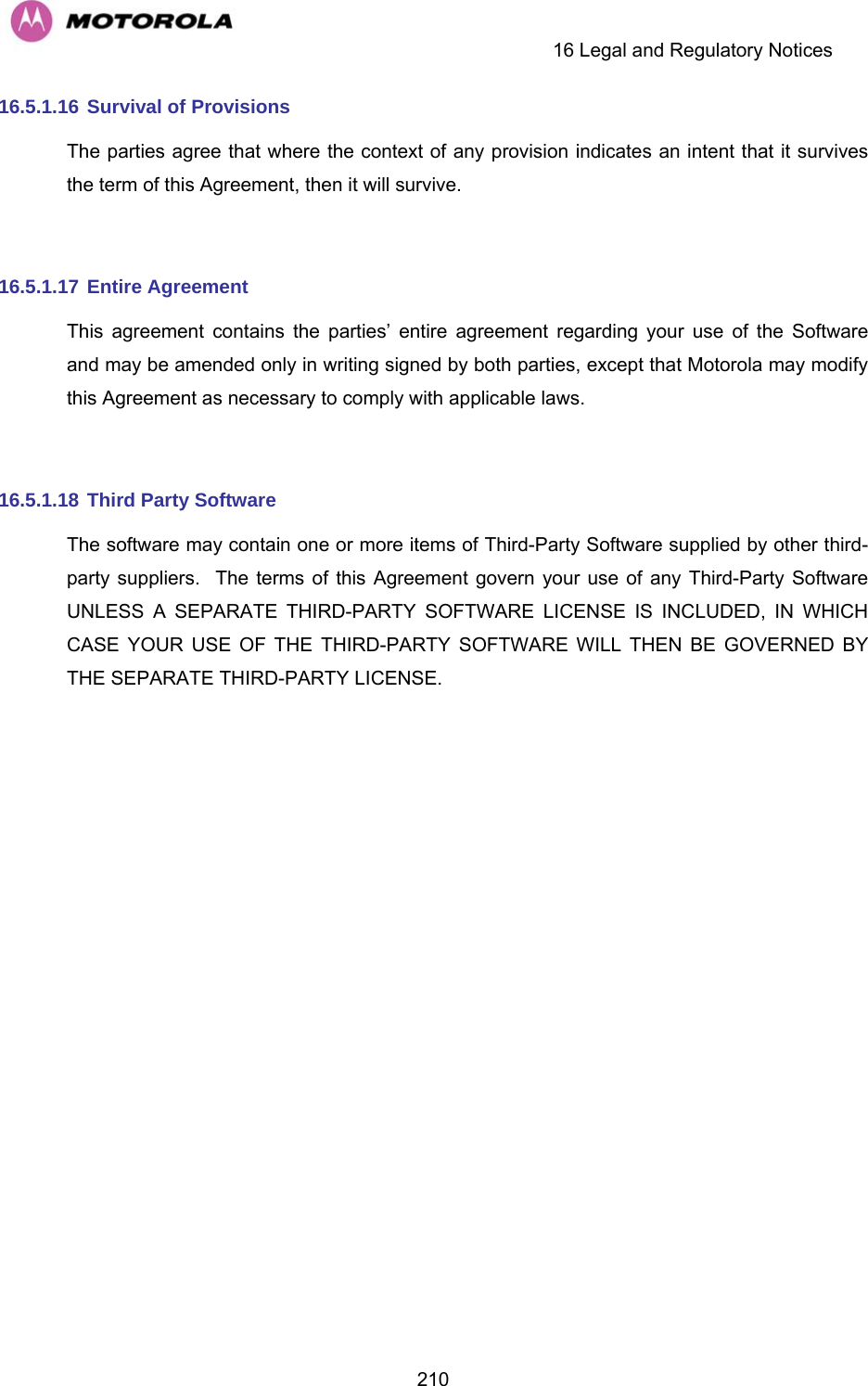
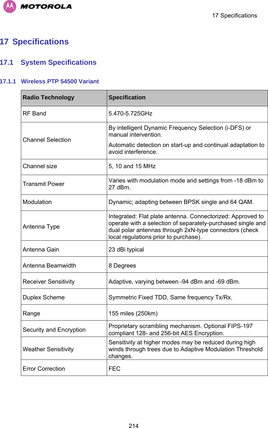
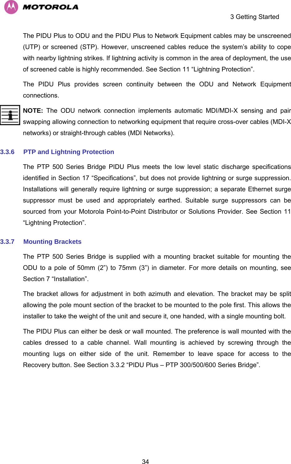
![13 PTP 500 Series Bridge – Connectorized Model 173The external antennas can be either dual-polarization (as the integrated antenna) or two single polarized antennas can be used in a spatially diverse configuration. It is expected that the dual-polarization antennas would normally be used to simplify the installation process; spatially diverse antennas may provide additional fade margin on very long LOS links where there is evidence of correlation of the fading characteristics on Vertical and Horizontal polarizations. Dual polarization antennas (with a gain greater than the integrated antenna) are currently only available in parabolic dish form. 13.5 Link Budget An estimate of the link budget for a specific application can be obtained by using the Motorola Systems link estimation tools. For more information see the Motorola web site. 13.6 Regulatory Issues Installations must conform to any applicable local regulations for the Equivalent Isotropic Radiated Power (EIRP). Ensuring compliance becomes more complex when the connectorized unit is used with external antennas which may be locally sourced. With higher gain external antennas fitted, the Maximum Transmit power may need to be reduced for operation in specific countries. See Section 5.2 “Licenses and Region Codes” for any EIRP restrictions that may apply in your region. In some regions, operation of the PTP 54500 products is constrained by an EIRP limit. The normal constraint is that the EIRP does not exceed 30 dBm (36 dBm for PTP 58500) for radio signals with a bandwidth of >=20 MHz. As the PTP 54500 operating bandwidth is approximately 15 MHz, then the limit is 34.8 dBm EIRP (28.8 dBm for PTP 58500). When operating with external antennas, the installer/operator has to set the maximum transmit power to ensure that the EIRP limit is not exceeded. The Set_Max_Transmit_Power is calculated as below: Set_Max_Transmit_Power = [Max_Transmit_Power] rounded down to nearest lower dB.](https://usermanual.wiki/Cambium-Networks/58500.Manual/User-Guide-992908-Page-175.png)