Cambium Networks 58XX WIRELESS ETHERNET BRIDGE User Manual Orthogon Systems
Cambium Networks Limited WIRELESS ETHERNET BRIDGE Orthogon Systems
UserManual.wiki
>
Cambium Networks
>
58XX User Manual
Users Manual
Navigation menu
Upload a User Manual
Namespaces
Wiki Guide
HTML
PDF
Info
Views
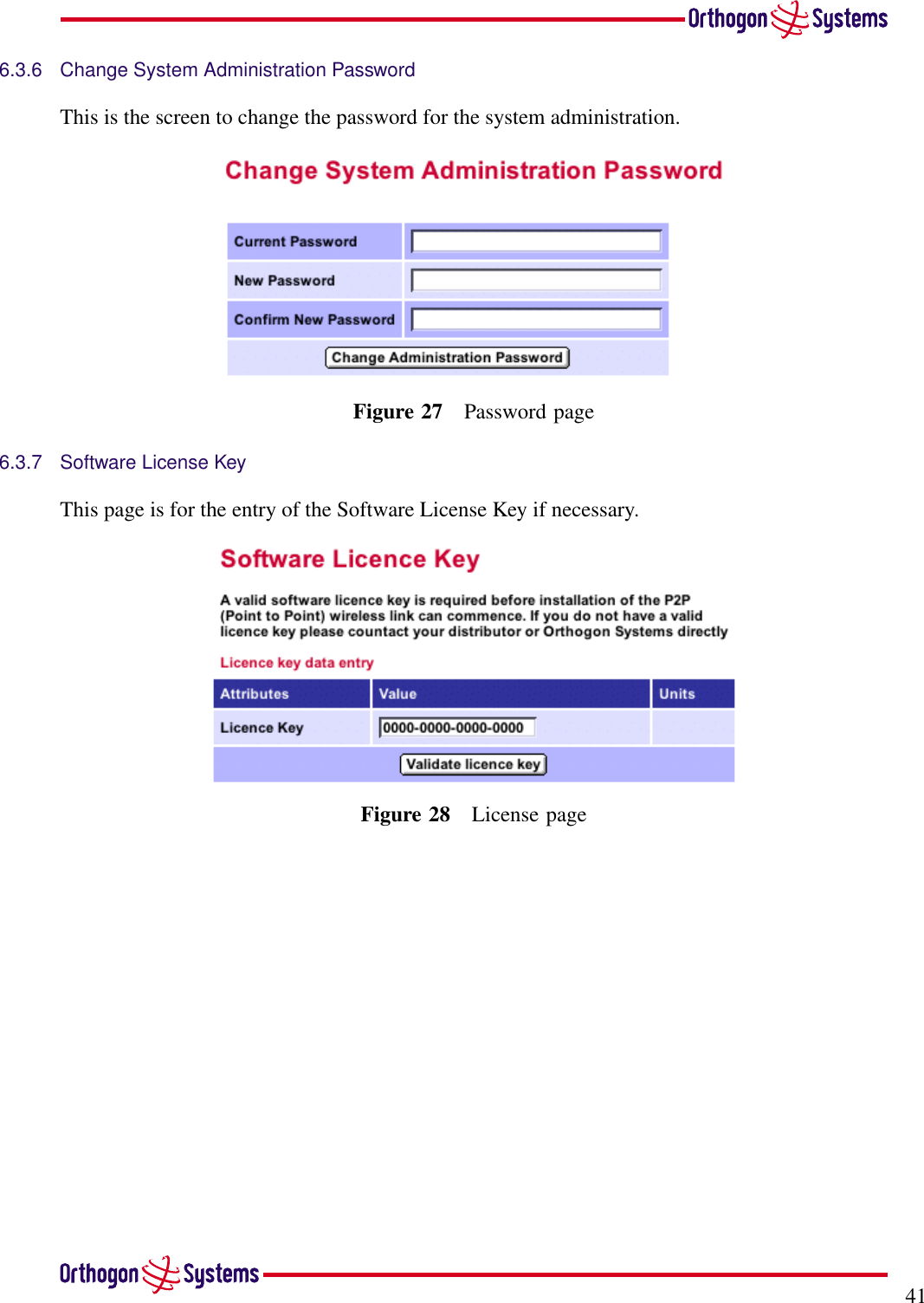
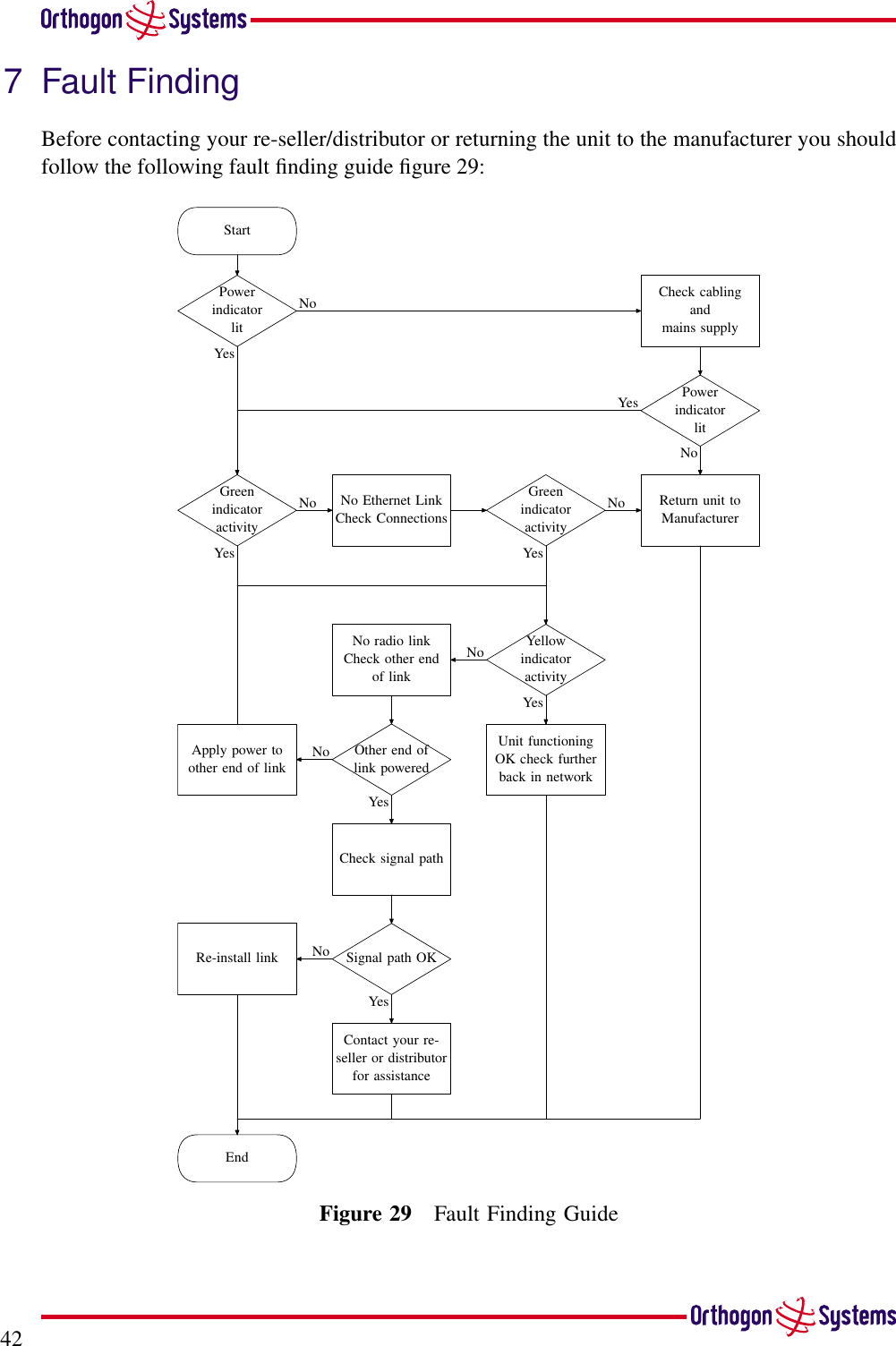
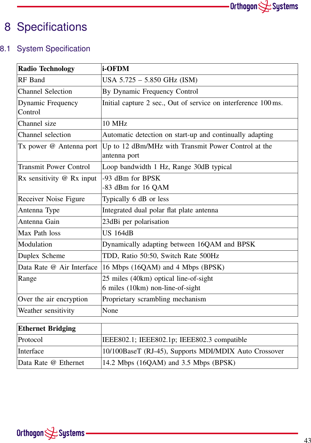
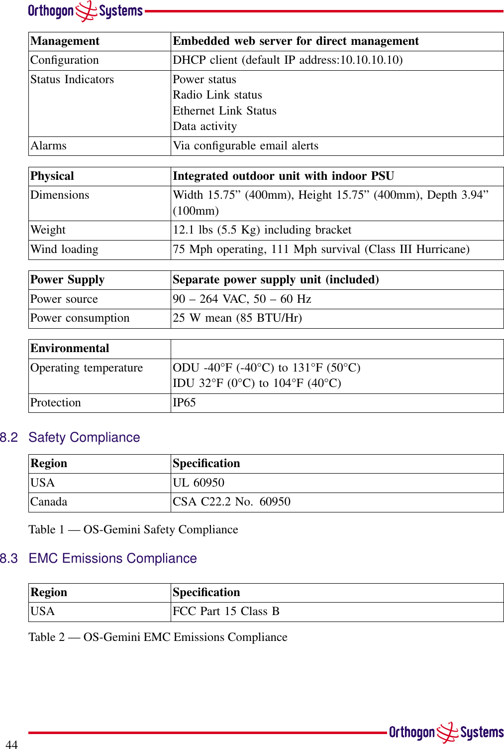
User Manual
Discussion / Help
Navigation

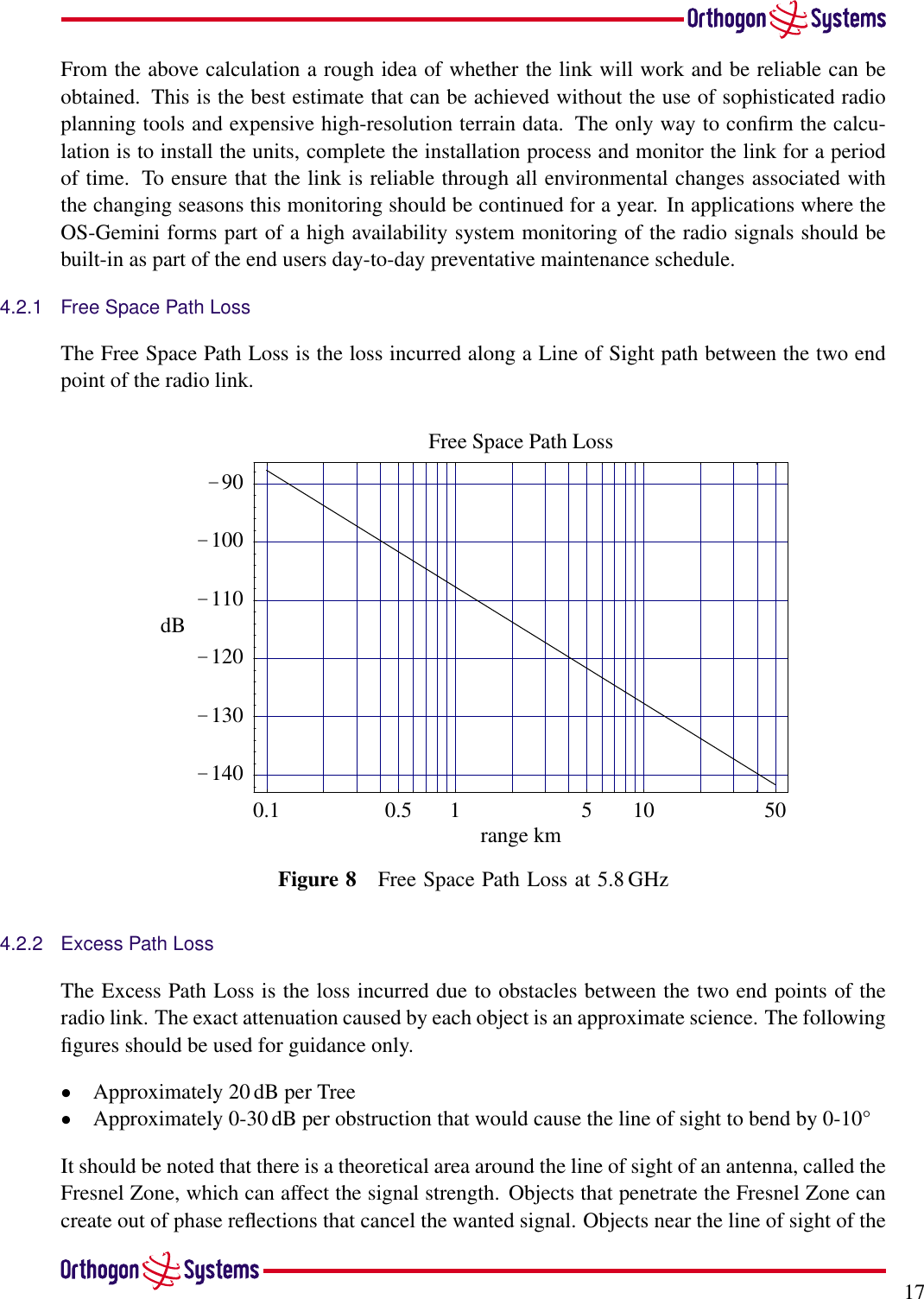
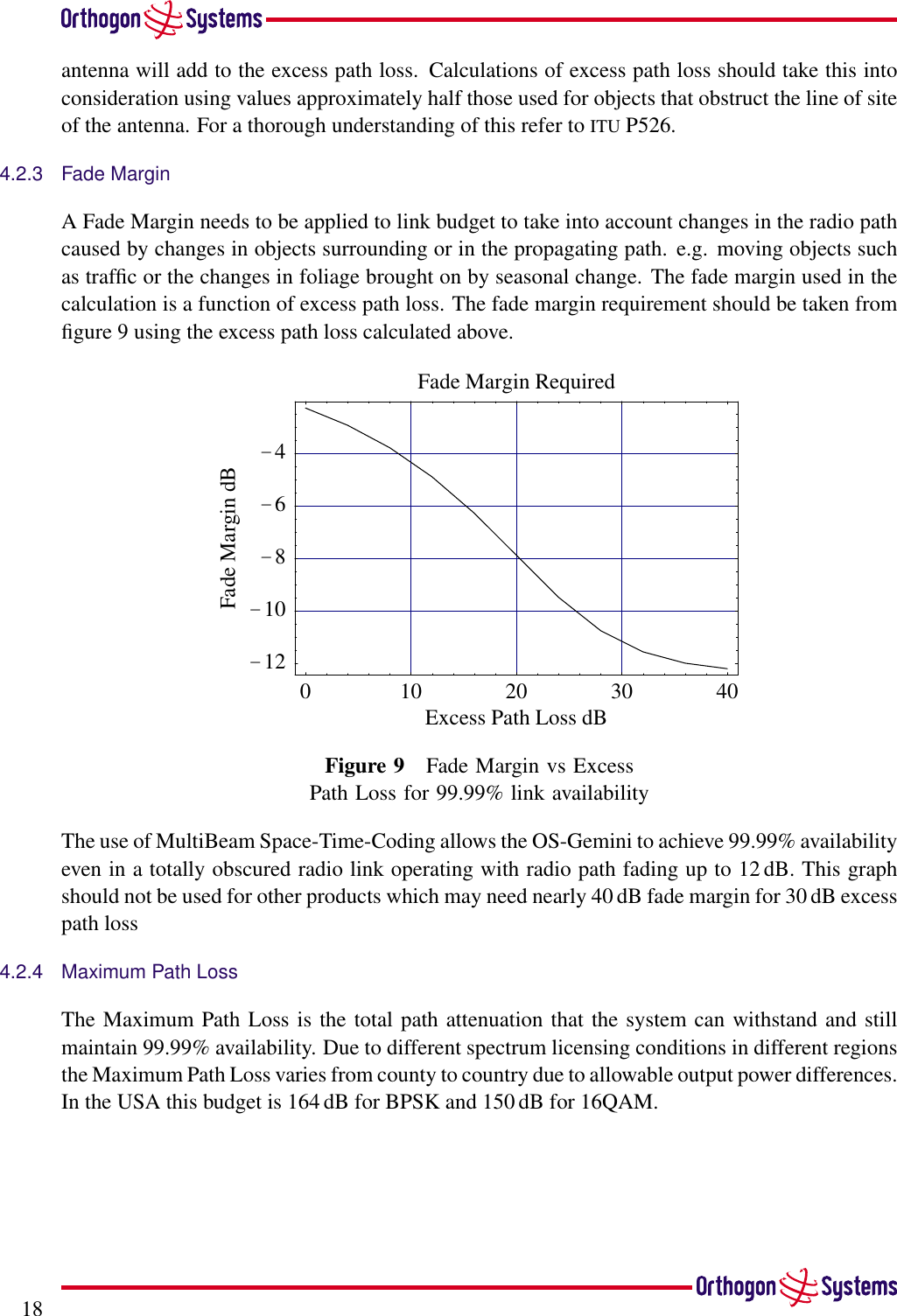
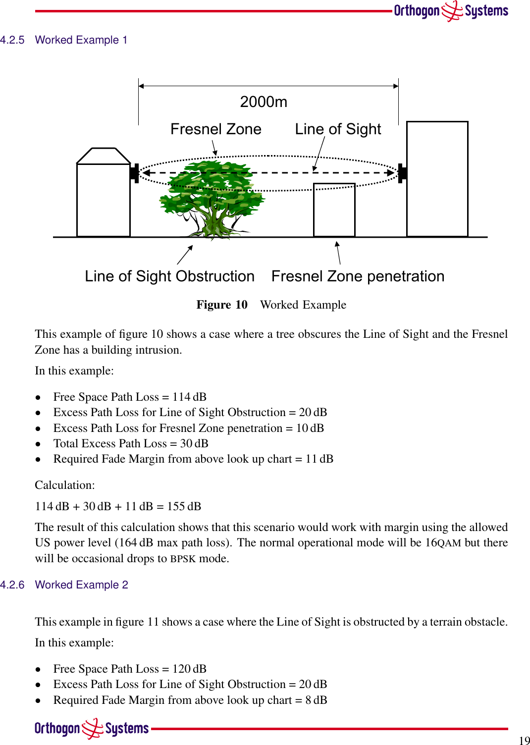
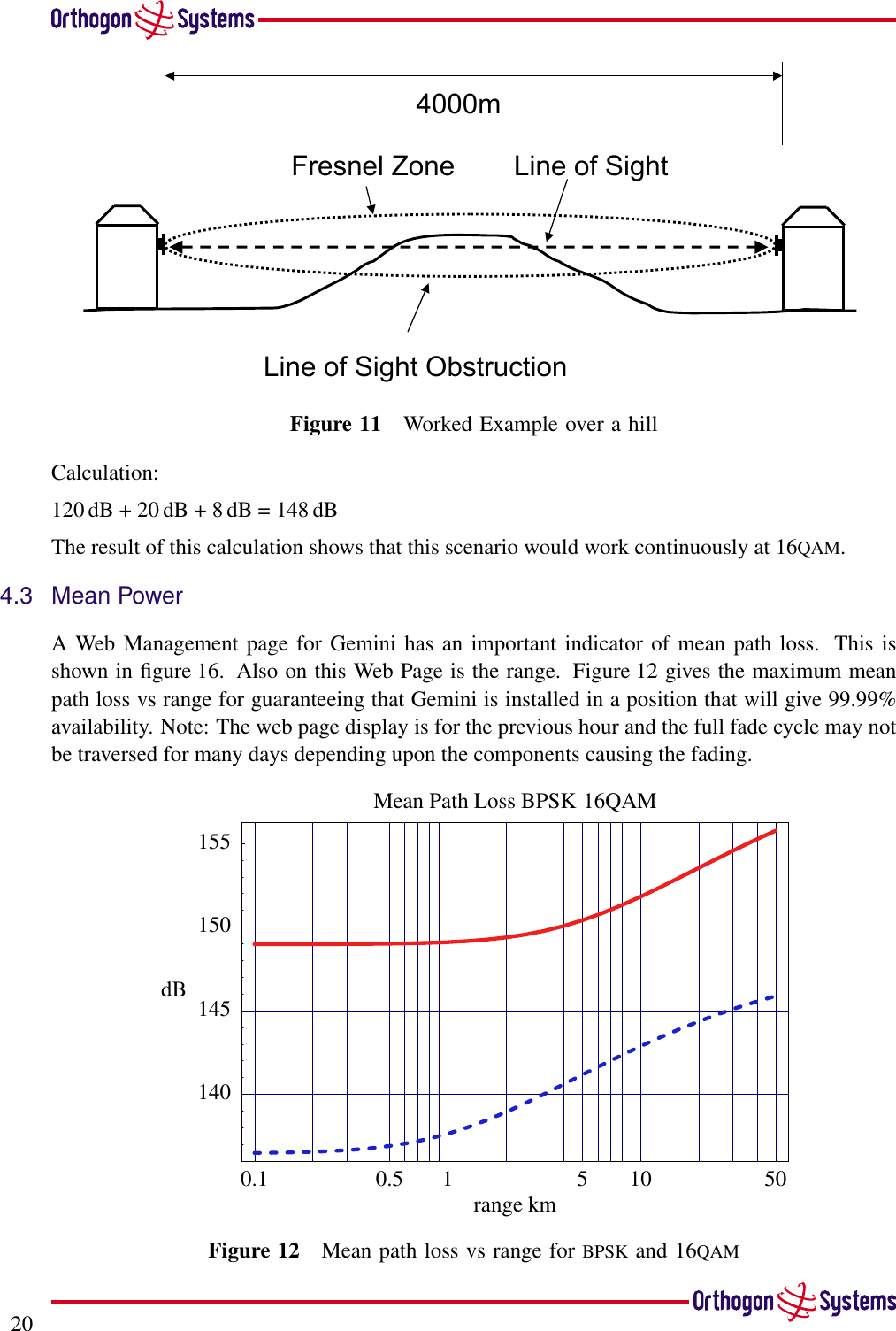
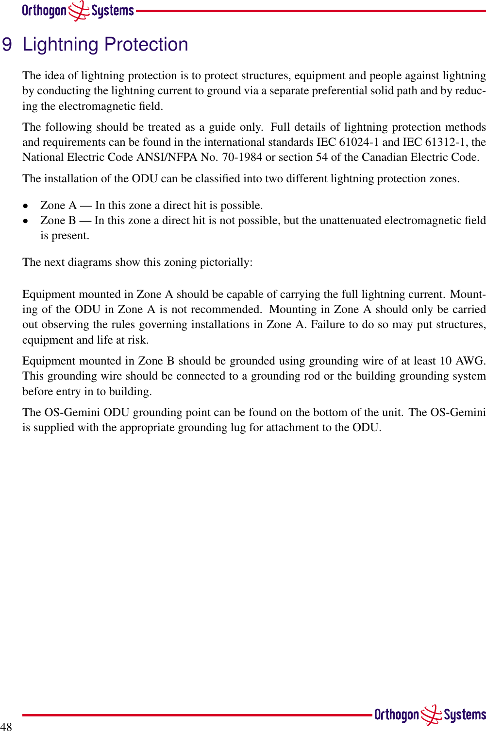
![49Zone AZone BZone AZone BODU mounted inside Zone B ODU mounted in Zone AZone AZone B]ODU mounted inside Zone BFigure 31 ODU Mounting Positions](https://usermanual.wiki/Cambium-Networks/58XX/User-Guide-328359-Page-51.png)