Cambium Networks 58XX-S Wireless Ethernet Bridge User Manual OS Gemini 5820
Cambium Networks Limited Wireless Ethernet Bridge OS Gemini 5820
Contents
- 1. Users Manual Part 1
- 2. Users Manual Part 2
Users Manual Part 2
51
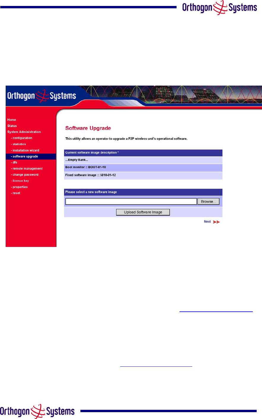
6.3.4 Software Upgrade
The OS-Gemini system has two software image banks; one is a fixed image which is stored in
protected non-volatile memory, the second bank is used by the system administrator to
upgrade the firmware as and when necessary. Figure 21 shows the main software upgrade
webpage.
Figure 21 Software Upgrade
The ‘Fixed’ image is only used if disaster recovery is required, i.e. if an upgrade process is
interrupted or the units are reset to their factory defaults.
These pages are used to update a unit’s operational software. The software image to be
uploaded should be downloaded to local storage from the Orthogon Systems website. The
software image is delivered by Orthogon Systems as a compressed zip file. Once the zip file
has been downloaded the user should extract the OS-Gemini Software image. This is easily
identifiable by its ‘.dld’ file extension.
The first step (Figure 21) is to use the “Browse” button to locate the software image previously
downloaded to local storage from the Orthogon Systems website. Once the image is located
the user should press the “Upload image to wireless unit” button to start the software upgrade
process.
52
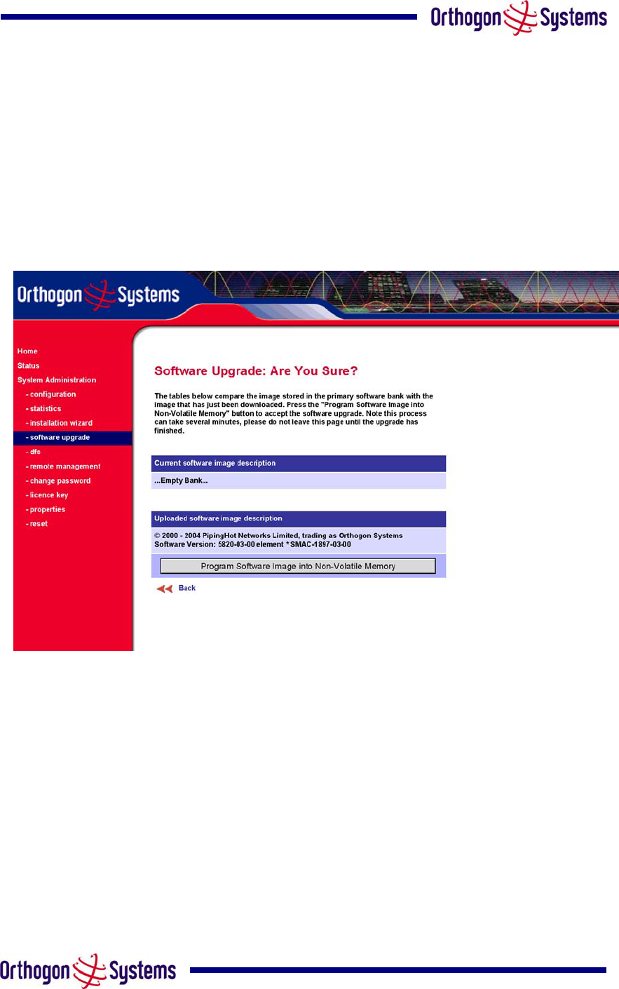
The software image will now be uploaded to the unit where it will be stored in SDRAM until it is
committed to the unit’s non-volatile memory. This upload should only take a few seconds, once
complete the image is verified and validated to ensure that no errors occurred during transfer
and the image is valid to run on the current platform. If there are any problems a warning
screen will appear.
The unit being upgraded will now display information about the build it currently has stored in
the image bank and the one that’s just been uploaded. If the image is not the right one the user
has the option to go back and reload a new image. (See Figure 21)
Figure 22 Software Upgrade Image Check
The user should ensure that he is happy to proceed before pressing the “Program Software
Image into Non-Volatile Memory” button. Once this button has been pressed the image is
stored into non-volatile memory, this process can take up to 60 seconds and must not be
interrupted.
53
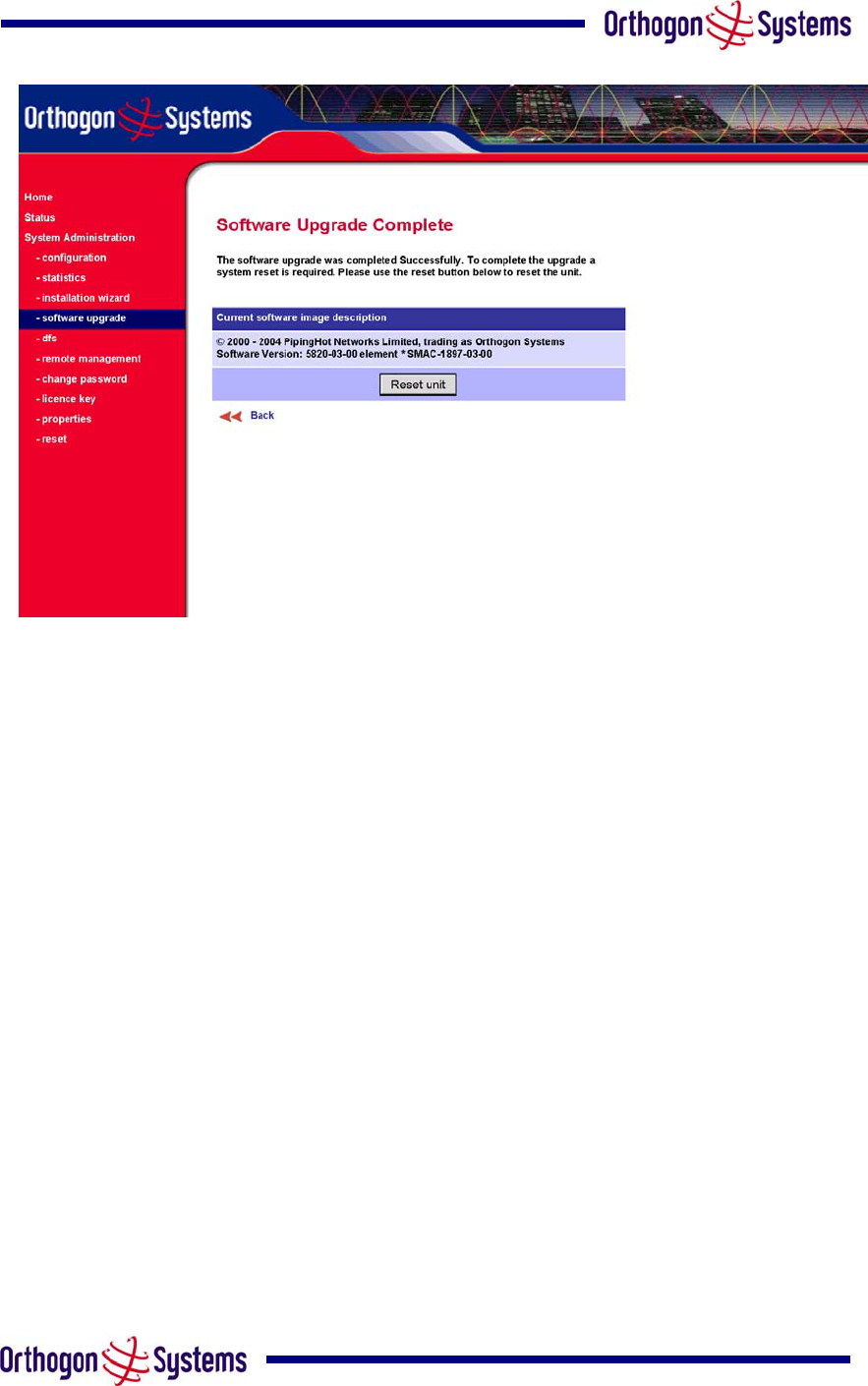
Figure 23 Software Upgrade Complete
When the software image has been written to non-volatile memory Figure 23 will be displayed
showing the status of the software upload.
Reset the unit by clicking the Reset Unit button. This will reset the unit within 30 seconds,
during this time you will not be able to communicate with the unit. The unit is now fully
functional.
If this screen is not displayed after 60 seconds this could indicate a problem with the memory
update process.
The user should now power cycle the unit to start using the new software image. The unit’s
boot software will automatically determine the health of the newly uploaded software image. If
any problems were encountered the boot code will revert to a protected fixed software image
After the power cycle the user should check that the required software image is loaded and
running by re-entering the Upgrade page where the software bank status will be displayed.

54
6.3.5 Dynamic Frequency Selection (DFS)
Dynamic Frequency Selection (hereafter referred to by the acronym DFS) is the OS-Gemini
wireless feature that monitors the available wireless spectrum and directs both ends of the
wireless link to operate on a channel with the minimum level of co and adjacent levels
interference.
6.3.5.1 Wireless Channels
The OS-Gemini wireless operates using a set of predefined overlapping channels. There are
19 predefined channels starting at 5734 MHz and ending at 5842 MHz. Each channel occupies
11 MHz of wireless spectrum and is offset in centre frequency from its neighbouring channel by
6 MHz.
It is important to note that adjacent channels on the DFS display have a 5 MHz overlap to the
adjacent channel.
6.3.5.2 DFS Measurements
The OS-Gemini wireless units perform four DFS measurements per TDD cycle, per channel.
The measurements are subdivided into two signal peak measurements and two mean signal
measurements. The peak measurements represent the peak received signal power with a
resolution down to 100 nS. The mean measurement represents the mean received signal
power for the 40 µS measurement period.
The DFS algorithm collects DFS measurements equally from all channels. This process is
called the Channel Availability Check (hereafter referred to by the acronym CAC). The CAC
uses a round-robin channel select process to collect an equal amount of DFS measurements
from each channel. It is important to note that the CAC measurement process is not altered by
channel barring process. Measurements are still collected for all channels irrespective of the
number of barred channels.
6.3.5.3 Measurement Analysis
DFS uses statistical analysis to process the received peak and mean measurement. The
statistical analysis is based on a fixed measurement quantisation period. The default
quantisation period is one minute. DFS collects data for the specified quantisation period and
only at the end of the period is the statistical analysis performed. The analysis produces four
key metrics for each channel:
• Peak of Peaks
• Peak of Means
• 99.9% Percentile of the Means
• Mean of Means
55
Peak of Peaks is the largest peak interference measurement encountered during the
quantisation period. This metric is useful for detecting large short duration spikes in the
interference environment.
Peak of Means is the largest mean interference measurement encountered during the
quantisation period. The peak of means is similar to the peak of peaks and is useful for
detecting slightly longer duration spikes in the interference environment.
99.9% Percentile of the Means is the value of mean interference measurement for which
99.9% of all mean measurements fall below during the quantisation period. The 99.9%
percentile metric is useful for detecting short duration repetitive interference that by its very
nature has a minimal effect of the mean of means.
Mean of Means is the arithmetic mean of the measured means during a quantisation period.
The mean of means is a coarse measure of signal interference and gives an indication of the
average interference level measured during the quantisation period. The metric is not very
good and predicting intermittent interference and is included to show the spread between the
mean of means, the 99.9% percentile and the peak of means.
Important Note. This release of DFS uses the 99.9% percentile as the prime interference
measurement. All subsequent references to interference level refer to this percentile
measurement.
6.3.5.4 The DFS Master / Slave Relationship
By default DFS operates in a master / slave relationship. The master is assumed to be the link
master configured during installation. All DFS configuration changes MUST be performed from
the master, to enforce this the DFS webpage has a different appearance depending if you are
viewing the data from the master or slave.
All configuration changes are applied at the master only. All configuration changes are
messaged from the master to the slave using the OS-Gemini MAC to MAC management
messages. Any DFS configuration messages received at the slave are stored in non-volatile
memory. This enables both master and slave to keep identical copies of DFS configuration
data in their non-volatile memories. It is therefore possible to swap master and slave roles on
an active Point-to-Point link without modifying DFS configuration.
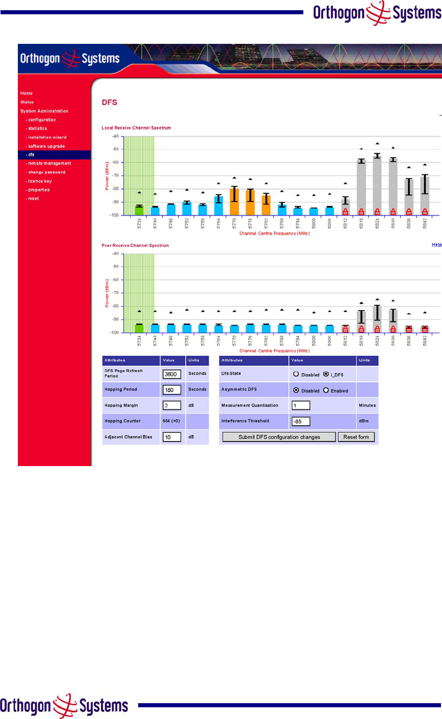
Figure 24 shows an example DFS webpage as seen from the master. Figure 25 shows an
example DFS webpage as seen from the slave. It should be noted that all the key DFS
configuration attributes are not available on the slave webpage.
56
Figure 24 DFS as seen from the Master
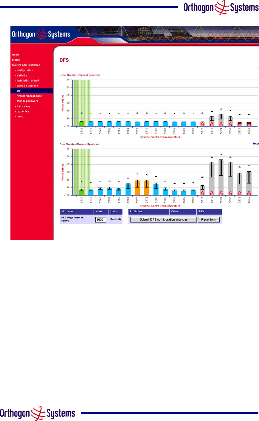
57
Figure 25 DFS as seen from the Slave
6.3.5.5 DFS Configuration
The following section describes the user modifiable configuration assessable from the DFS
webpage. It is recommended that the default values maintained. If the user believes that the
performance of the DFS algorithm required some modifications this should only be done after
consulting your distributor or one of the Orthogon Systems field support engineers.
Refresh Page Period The DFS page refreshes automatically according to the setting entered
here (in seconds).
Hopping Period The DFS algorithm evaluates the DFS metrics every ‘Hopping Period’ seconds
(180 seconds by default) looking for a channel with lower levels of interference. If a better
channel is located then DFS performs an automated channel hop. If SNMP and or SMTP alerts
are enabled an SNMP TRAP and or an email alert is sent warning the system administrator or
the channel change. (Default 180 Seconds).

58
Hopping Margin DFS uses this margin when making a channel hop decision. The channel to
hop to has to have an interference level 2 dBs (default) better than the current active channel.
(Default 2 dB)
Hopping Counter is used to record the number of channel hops. The number in the “(+ )”
brackets indicates the number of channel changes since the last screen refresh.
Adjacent Channel Bias To prevent DFS from selecting channels that overlap or are adjacent to
channels with high levels of interference the DFS algorithm applies a bias to the channel
evaluation algorithm.
The Adjacent channel bias (ACB) is applied as follows:
)4()3()2()5(
)5()2()3()4(
4321
1234
ACBnACBnACBnn
nACBnACBnACBn
BiBiBii
iiBiBiBi
B−+−+−+++
+++−+−+−
=
++++
−−−−
Where:
k
i Interference measurement from the kth channel.
ACB
B Adjacent Channel Bias from the DFS configuration
webpage (dB).
n Channel index.
B
Resultant Channel bias used to make channel hop
decisions.
Equation 3 Adjacent Channel Bias
The adjacent channel bias calculation is performed on both the master and slave ends of the
wireless link. The way in which DFS processes the channel bias information is dependant on
the current Asymmetric DFS configuration setting. If the link is in its default Asymmetric
configuration setting of ‘Symmetric’ then the master uses the peak of master and slave bias
measurements to make the channel hop decision. If DFS is configured as ‘Asymmetric’ then
the DFS channel hop algorithm works independently using on the local channel bias
measurements and ignores the bias measurements computed by its peer. (Default 10 dB).

59
DFS State is used to enable and disable operation of the DFS algorithm. When DFS is
disabled interference measurements are still processed and displayed but channel hopping is
not performed.
Asymmetric DFS. The default configuration of symmetric constrains DFS to operate using the
same transmit and receive channel. When in symmetric mode the slave unit will always follow
the master. If the master moves to a new channel the slave will hop to the same channel.
When the Point-to-Point link is configured as an asymmetric link both the master and slave a
free to select the best channel from their own set of local interference metrics. (Default
Symmetric).
Measurement Quantisation. DFS uses statistical analysis to process the received peak and
mean measurement. The statistical analysis is based around a fixed measurement quantisation
period. The default quantisation period is one minute. DFS collects data for the specified
quantisation period and only at the end of that period is the statistical analysis performed.
Increasing the measurement quantisation period will reduce the dynamic response time of the
algorithm but increase the statistical significance of the metrics. (Default 1 minute)
Interference Threshold. DFS uses the interference threshold to perform instantaneous channel
hops. If the measured interference on a channel exceeds the specified threshold then DFS will
instruct wireless immediately search for a better channel. If a better channel cannot be found
then OS-Gemini will continue to use the current active channel. (Default –85 dBm)
6.3.5.6 Barring Channels
Channels can only be barred / unbarred by the system administrator from the master DFS
webpage. The barring / unbarring operations are disabled on the slave webpage. If an attempt
to bar / unbar a channel is made at the slave a warning dialog is generated.
Barring / Unbarring of channels is performed by clicking the appropriate channel on the local or
peer channel spectrum plots on the master webpage. Each bar / unbar attempt will be
proceeded by a conformation dialog. It should be noted that the channel bar will take effect
immediately and is not related to the measurement quantisation period.
6.3.5.7 Local and Peer Channel Spectrum Graphics
DFS presents its computed statistical measurements in a graphical display on both the master
and slave DFS webpage.
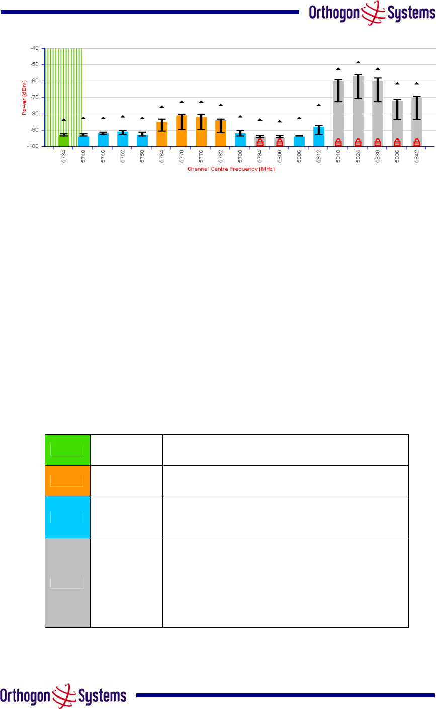
60
Figure 26 Example DFS Graphic
The X-axis shows a stylised view of the 19 selectable wireless channels. It is important to note
that adjacent channels on the DFS display have a 5 MHz overlap. The display separates the
display of channels to help the clarity of the resultant display. The axis is labelled using the
channel centre frequencies in MHz (5734 to 5842 MHz).
The Y-axis shows the interference power levels from –100 to –40 dBm.
The active channel (channel 1 in Figure 26) is always marked using hatched green and white
lines. The width of the hatching is directly proportional the 11 MHz spectral occupancy of the
channel.
The individual channel metrics are displayed using a coloured bar, an ‘I’ bar and a peak
symbol.
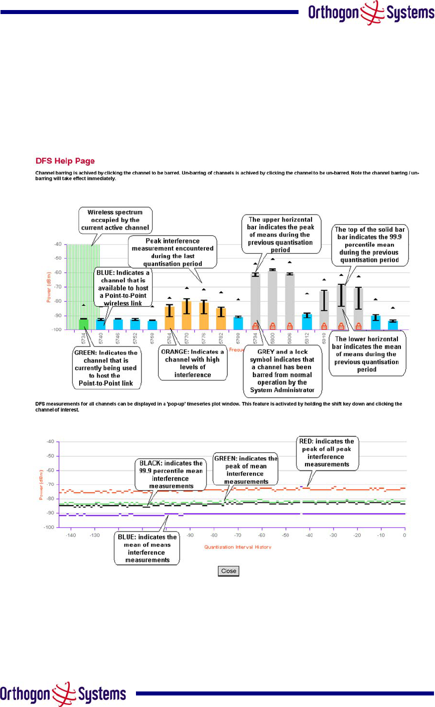
The coloured bar represents the following channel state:
Green Active The channel is currently in use hosting the
Point-to-Point wireless link
Orange Interference The channel has interference above the interference
threshold
Blue Available The channel has an interference level below the
interference threshold and is considered by the DFS
algorithm suitable for hosting the Point-to-Point link
Grey Barred
The system administrator has barred this channel
from use. Because the low signal levels
encountered when a unit is powered up in a
laboratory environment prior to installation (which
makes the grey of the channel bar difficult to see).
An additional red ‘lock’ symbol is used to indicate
that a channel is barred.
Table 6 DFS change state key
The top of the coloured bar represents the 99.9% percentile metric for specific channel.
61
The ‘I’ Bar is used to display the mean of means and peak of means metrics. The lower
horizontal bar represents the mean of means and the upper horizontal bar represents the peak
of means. The vertical bar is used as a visual cue to highlight the statistical spread between the
peak and the mean of the statistical distribution.
The peak symbol (the upper small triangle above each channel ‘I’ bar) is used to indicate the
peak of peaks interference measurement.
6.3.5.8 Viewing Historic DFS Metrics
DFS allows the system administrator to view the results of previous measurement quantisation
periods. Holding down the shift key and clicking the appropriate channel on the local channel
spectrum plots activates this feature. This feature is available on both the master and slave
webpage.
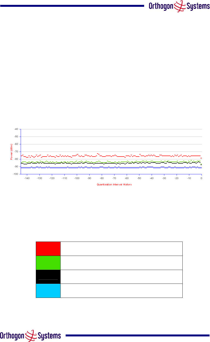
Figure 27 DFS Timeseries Plot
Figure 27 shows an example DFS time series plot. A timeseries plot displays the previous 145
measurement quantisation periods. If the OS-Gemini unit has not been running for 145
quantisation periods then only the number of measurement quantisation periods that are
available are displayed.
RED Peak of Peaks interference measurement
GREEN Peak of Means interference measurement
BLACK 99.9% percentile of means interference measurement
BLUE Mean of Means interference measurement
Table 7 DFS timeseries key
62
6.3.5.9 DFS Online Help
Because the DFS displays contain a large amount of data, symbols and colour references, an
online help screen has been provided. This screen is accessible from both the master and
slave webpages.
Figure 28 gives a high level overview of the DFS webpage.
Figure 28 DFS Help Page

64
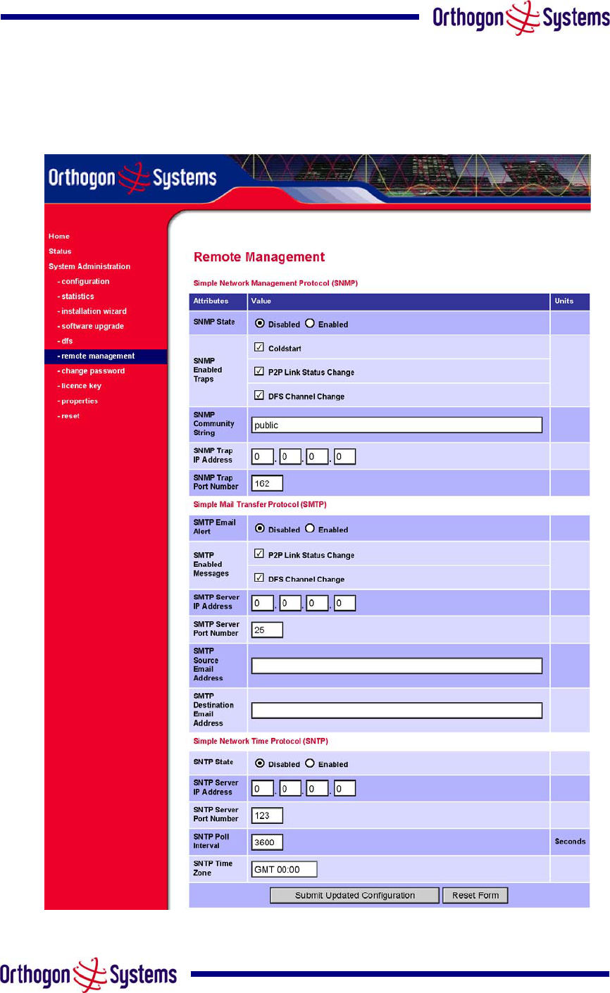
6.3.6.1 SNMP (Simple Network Management Protocol)
The industry standard remote management technique is SNMP (Simple Network Management
Protocol). The OS-Gemini supports SNMP version 1 and version 2.
6.3.6.1.1 Supported Management Information Bases (MIBS)
The industry standard remote management technique is SNMP (Simple Network Management
Protocol). The OS-Gemini supports SNMP version 1 and version 2.
The OS-Gemini SNMP stack currently supports three distinct MIBs.
MIB-II, RFC-1213
The OS-Gemini supports the ‘System Group’ and ‘Interfaces Group’.
Bridge MIB, RFC-1493
The OS-Gemini supports the ‘dot1dBase Group’ and the ‘dot1dBasePortTable Group’.
SNMP TRAPs
‘Cold Start, ‘Link Up’, 'Link Down’, DFS Channel Change TRAPs are supported.
Orthogon Systems MIB, Proprietary MIB definition
For a copy of the Orthogon Systems proprietary MIB RFC please visit the Orthogon Systems
website.
6.3.6.1.2 SNMP Configuration
SNMP State The SNMP state attribute controls the creation of the SNMP features. Changing
the SNMP state attribute requires a mandatory reset of the unit. Only when the SNMP state is
enabled at system start-up will the SNMP processor task be created.
SNMP Enabled Traps The SNMP Enabled Traps attribute controls which SNMP Traps the unit
will send.
SNMP Community String The SNMP community string acts like a password between the
networks SNMP management entity and the distributed SNMP clients (OS-Gemini units). Only
if the community string is configured correctly on all SNMP entities can the flow of management
information take place. By convention the default value is set to ‘public’. When the community
string is changed the system requires a mandatory reset before the new string or phrase is
adopted.

65
SNMP Trap IP Address Is the address of either the network SNMP manager or Trap receiver.
When asynchronous events (Traps in SNMP terminology) are generated the client unicasts
these to this IP Address. When the address is changed the system requires a mandatory reset
before the setting is adopted
SNMP Trap Port Number The SNMP Trap Port Number is the port number of either the
networked SNMP manager or Trap receiver. By convention the default value for the port
number is 162. When the port number is changed the system requires a mandatory reset
before the setting is adopted.
6.3.6.2 SMTP (Simple Mail Transport Protocol)
The SMTP client is an alternative method for the OS-Gemini to alert the outside world when
there are or have been system errors
SMTP Email Alert This attribute controls the activation of the SMTP client.
SMTP Enabled Messages The SMTP Enabled Messages attribute controls which email alerts
the unit will send.
SMTP IP Address The IP address of the networked SMTP server.
SMTP Port Number The SMTP Port Number is the port number used by the networked SMTP
server. By convention the default value for the port number is 25.
SMTP Source Email Address The email address used by the OS-Gemini to log into the SMTP
server with. This must be a valid email address that will be accepted by your SMTP Server
SMTP Destination Email Address The email address to which the OS-Gemini will send the alert
messages.
66
6.3.6.3 SNTP (Simple Network Time Protocol)
The SNTP client allows the OS-Gemini to obtain accurate date and time updates from a
networked timeserver. The resultant time information is used by the SNMP, webpage and
System Reset tasks.
SNTP State The SNTP state attribute controls the creation of the SNTP features.
SNTP IP Address The IP address of the networked SNTP server.
SNTP Port Number The port number of the networked SNTP server. By convention the default
value for the port number is 123.
SNTP Poll Interval The period at which the SNTP client polls the server for time correction
updates. Default 1 hour. If for any reason an SNTP poll fails the client will automatically
perform 3 retries before waiting for the user defined poll period.
SNTP Time Zone The SNTP time zone is a fixed offset from GMT that is added to the correct
time to allow the expression of time in all geographic time zones.
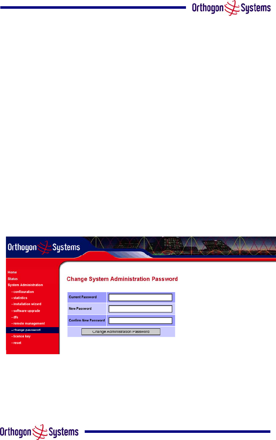
6.3.7 Change System Administration Password
This page (Figure 30) is used to change the password for the system administration (The
factory default is blank).
Figure 30 Password Change
To change the password any combination of alphanumeric characters, up to 32 characters in
length, can be used.
67
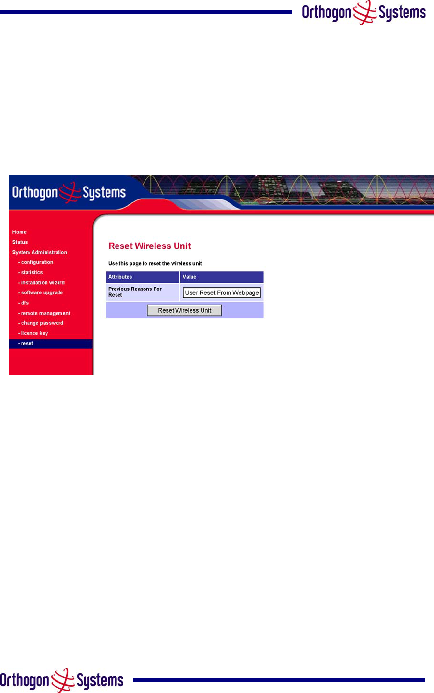
6.3.8 Reset
The reset page allows the system administrator to perform commanded resets of the wireless
unit. The reset page also allows the system administrator to view a list of past reset reasons.
The ‘reasons for reset’ field has been implemented as a drop down selection box, where the
latest reason for reset is located at the top of the list.
If the SNTP service from the remote management section above is active then the command
reset commands will be accompanied by the date and time the reset was requested.
Figure 31 System Reset
68
7 Fault Finding
If communication has been lost with the unit at the near end of the link then there may be a
hardware fault with the wiring, network or hardware. Go to the hardware section below. If
communication with the far end of the link is lost then go to the radio section below.
7.1 Hardware
If there are problems suspected with the link hardware the following procedure is
recommended.
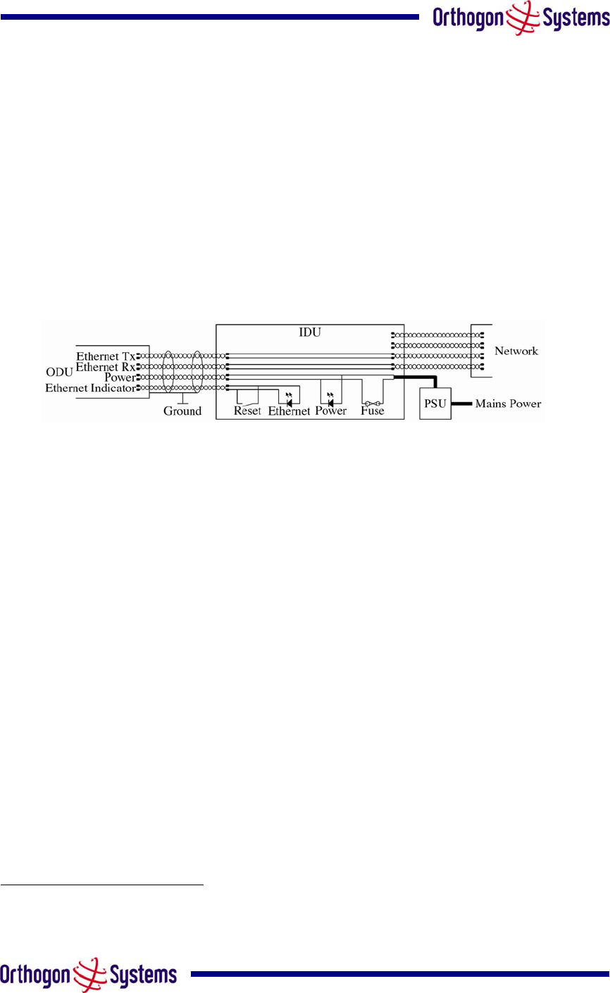
The following diagram illustrates the main system connections.
Figure 32 Main System Connections
7.1.1 Power
Check the power LED at each end of the link. If the power lights are illuminated go to the
Ethernet section below. If at either end they are not illuminated then4. Check the Ethernet LED.
If neither are illuminated then there is no voltage on the power wires to the ODU.
1. Check that the mains power is connected and switched on.
2. Check that the lamp illuminates if the ODU connector is disconnected at the IDU. (Remove
the IDU cover).
a. If it does illuminate then either the ODU is drawing to much current, or the power
wiring to the ODU is short circuit or the PSU is supplying insufficient power. The
likely fault can be determined by removing the fuse and measuring the current
taken with an ammeter placed across the fuse. This is normally 10ma without the
ODU connected and 300ma to 1amp when the ODU is connected.
b. If it does not illuminate then recheck that power is applied to the PSU, that the PSU
is plugged in to the IDU. Check that the IDU is not short circuit by measuring the
impedance across the Power connector. Is the lamp faulty or the fuse faulty.
4 The power indicator LED should be continually illuminated.

69
7.1.2 Ethernet
The Ethernet LED is driven from the ODU processor and thus is capable of informing you of
many conditions using different flash sequences. If the Ethernet indicator does not illuminate at
all there are four possible conditions.
1. There is no power reaching the ODU because of a wiring fault
2. The ODU is faulty
3. The IDU is faulty
4. The Ethernet network side is faulty
Look at the following table to check the LED response for power up, disconnect the power and
reapply and note what happens.
Differentiating between 1--3 and 4 can be achieved by removing the power for 1 second.
Watch the Ethernet indicator for 1 minute, if it never flashes then the problem is 1—3. Take the
fuse out of the IDU and check the current taken by the ODU. This should be 300ma to 1amp
when starting through to running normally.
If the Ethernet indicator flashes to begin with but then stops flashing then
Mode Green LED
Yellow LED
No Ethernet Cable
Connected
Yellow LED
Ethernet Cable
Connected between
IDU and
NIC/Switch/Hub
No Power Applied Off Off Off
Power Applied but
IDU Fuse Blown Off Off Off
Power Applied On
Will flash once per
second regularly
approximately 16
seconds after power
applied for 10
seconds then will go
out and stay out
Will flash once per
second regularly
approximately 16
seconds after power
applied for 10
seconds then
operate as Ethernet
Link/Activity LED
Valid Ethernet Link
and no traffic On N/A
Will be on solid for a
valid link.
Valid Ethernet Link
with traffic On N/A
Will be on solid, but
will blink randomly as
traffic passes through
Whilst Reset Switch
Pressed On Off Off

70
Reset Switch
Pressed and
released within 10
seconds during
normal operation
On Off
Off whilst switch
pressed but returns
to LINK/Activity state
when released. No
reset will take place
Reset Switch
Pressed and held for
> 20 seconds during
normal operation
On
Off whilst switch pressed.
One second after release, flashes twice per
second regularly for 10 seconds, then erases
non-volatile configuration data and resets.
The erasure will reset all the unit's
configuration apart from the last known
wireless link configuration, this ensures that
after a reset the wireless link SHOULD re-
establish without any user intervention.
The IP address which will be reset to
10.10.10.10
Reset Switch
Pressed and held for
>40 seconds from
power on (Reset is
pressed whilst power
is applied)
On
Off whilst switch pressed.
One second after release, flashes twice per
second regularly for 10 seconds, then erases
non-volatile configuration data & the
downloaded image and resets.
The erasure will reset all the unit's
configuration apart from the last known
wireless link configuration, this ensures that
after a reset the wireless link SHOULD re-
establish without any user intervention.
The IP address which will be reset to
10.10.10.10 and the unit will boot the fixed
software image.

71
7.2 Radio
7.2.1 No Activity
If communication over the radio link has been lost and the unit at the other end of the link can
be managed on its local network. The following procedure should be adopted.
If there is no wireless activity then the configuration should be checked. It is essential that the
following items are correct
• Check that the software at each end of the link is the same
• Check that the Target Mac address has not been mis-configured at each end of the
link.
• Check Range
• Check Tx Power
• Check License key
• Check Master Slave
• Check for Alarm conditions on Home page
• Check that the link has not bee further obscured or the ODU misaligned.
• Check the DFS page at each end of the link and establish that there is a common
quiet wireless channel to use.
If there are no faults found in the configuration and there is absolutely no wireless signal retry
the installation procedure. If this doesn’t work then the ODU may be faulty.
7.2.2 Some Activity
If there is some activity but the link is unreliable or doesn’t achieve the data rates required then
• Check that the interference has not increased using the DFS measurements
• If a quieter channel is available check that it is not barred
• Check that the path loss is low enough for the communication rates required
• Check that the ODU has not become misaligned
72
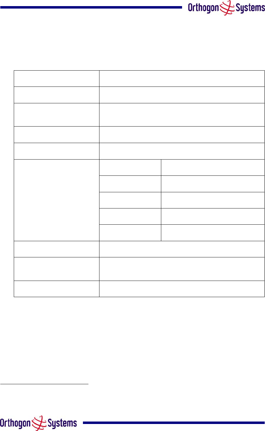
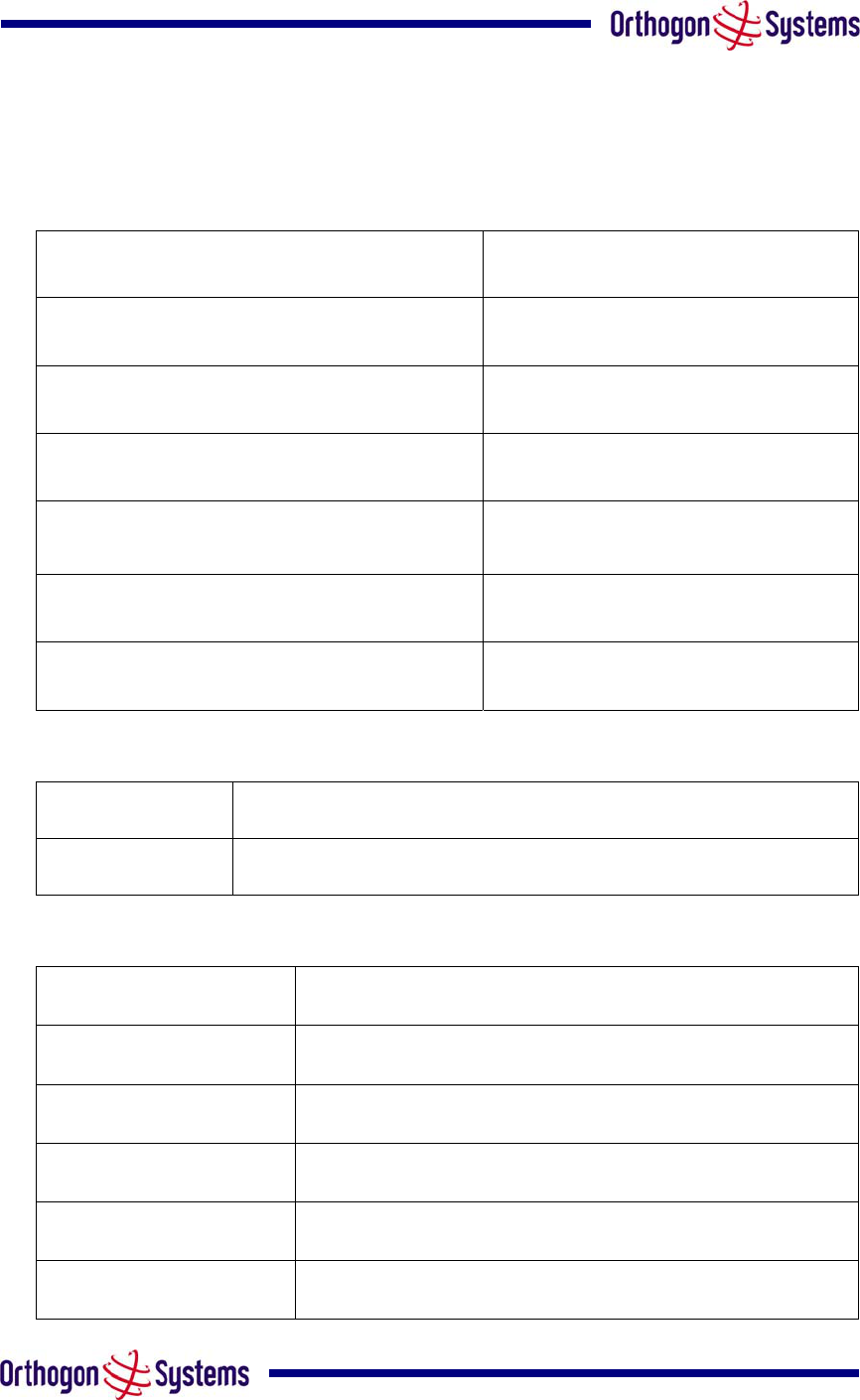
8 Specifications
8.1 System Specifications
Radio Technology Specification
RF Band 5.725-5.850GHz
Channel Selection By dynamic frequency control and manual intervention
Automatic detection on startup and continual adaption to
avoid interference.
Dynamic Frequency Control Initial capture 10-15 sec. Out of service on interference 100
ms.
Channel size 11 MHz
Tx power @ Antenna ports Mode Maximum Power Output
(region dependant)5
BPSK Mode 24 dBm
QPSK Modes 23 dBm
16QAM Modes 21 dBm
64QAM Modes 19 dBm
Transmit Power Control Loop bandwidth 1 Hz, Range 30dB typical
Manual Power Control Maximum power can be controlled lower than the power
limits shown above in order to control interference to other
users of the band.
Receiver Noise Figure Typically 6 dB
5 As specified by FCC Part 15.247
73
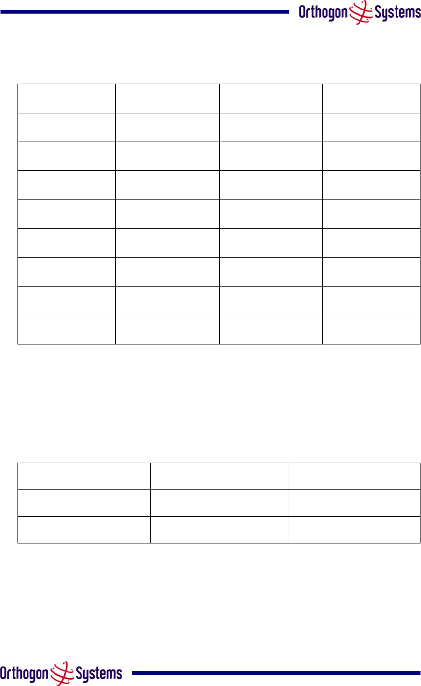
The receive sensitivities and system gains for each mode are as follows:
Mode RX Sensitivity TX Power System Gain
BPSK 1/2 -95.5 dBm 24 dBm 166.5 dB
QPSK 1/2 -92.8 dBm 23 dBm 162.8 dB
QPSK 2/3 -90.7 dBm 23 dBm 160.7 dB
16QAM 1/2 -88.1 dBm 21 dBm 156.1 dB
16QAM 3/4 -83.6 dBm 21 dBm 151.6 dB
64QAM 2/3 -80.2 dBm 19 dBm 146.2 dB
64QAM 3/4 -78.3 dBm 19 dBm 144.3 dB
64QAM 7/8 -73.6 dBm 19 dBm 139.6 dB
The values quoted here are static sensitivity measurements. When AMOD is in operation,
margins are applied to the up and down shifts between modes to ensure seamless changes
without loss of data. The margins applied are dynamic and selected dependant on the
prevailing link conditions.
The margins applied are as follows:
Fading Mode Up Shift Mode Down shift
Slow 1.5 dB 1.5 dB
Fast 6 dB 3 dB
For example: In a fast fading environment an up shift from 16QAM ¾ to 64QAM 2/3 will occur
at –74.2 dBm (-80.2 dBm + 6 dB) and the down shift from 64QAM 2/3 to 16QAM ¾ will occur at
–77.2 dBm (-80.2 dBm + 3 dB).

74
Antenna
Antenna Type Integrated flat plate antenna
Antenna Gain 23.5 dBi typical
Antenna Beamwidth 8 Degrees
Wireless PHY
Max Path Loss 167dB
Duplex Scheme TDD, Symmetric (1:1) and Asymmetric (2:1)
Range 81 miles (130km) optical Line-of-Sight
6 miles (10km) non-Line-of-Sight
Over-the-Air Encryption Proprietary scrambling mechanism.
Optional AES – via licence update.
Weather Sensitivity Sensitivity at higher modes may be reduced
during high winds through trees due to
Adaptive Modulation Threshold changes
Error Correction FEC and ARQ
Management
Status Indication Power status
Ethernet Link Status
Data activity
Installation Web server and browser for setup
Audio tone feedback during installation
Web server for confirmation
Radio Performance and Management Via web server and browser, SNMP
Alarms Via configurable email alerts, SNMP

75
Ethernet Bridging
Protocol IEEE802.1; IEEE802.1p; IEEE802.3
compatible
Interface 10/100BaseT (RJ-45), Supports MDI/MDIX
Auto Crossover
Data Rate6 0 – 5 km Mode
(Single direction – Symmetric TDD (1:1))
BPSK 1/2 1.60 Mbps
QPSK 1/2 3.20 Mbps
QPSK 2/3 4.27 Mbps
16QAM 1/2 6.40 Mbps
16QAM 3/4 9.60 Mbps
64QAM 2/3 12.81 Mbps
64QAM 3/4 14.41 Mbps
64QAM 7/8 16.81 Mbps
Data Rate 0 – 5 km Mode
(Single direction – Asymmetric TDD (2:1))
BPSK 1/2 2.07 Mbps
QPSK 1/2 4.13 Mbps
QPSK 2/3 5.51 Mbps
16QAM 1/2 8.26 Mbps
16QAM 3/4 12.39 Mbps
64QAM 2/3 16.53 Mbps
64QAM 3/4 18.59 Mbps
64QAM 7/8 21.69 Mbps
Data Rate 0 – 40 km Mode
(Single direction – Symmetric TDD (1:1)) Reduces by 6.40%
Data Rate 0 – 40 km Mode
(Single direction – Asymmetric TDD (2:1)) Reduces by 8.11%
Data Rate 0 – 130 km Mode
(Single direction – Symmetric TDD (1:1)) Reduces by 19.63%
Data Rate 0 – 130 km Mode
(Single direction – Asymmetric TDD (2:1)) Reduces by 23.97%
Note: Practical Ethernet rates will depend on network configuration, higher layer
protocols and platforms used.
Physical
Dimensions Width 14.5” (370mm), Height 14.5” (370mm), Depth 3.75” (95mm)
Weight 12.1 lbs (5.5 Kg) including bracket
6 ARQ disable – (Enabling ARQ drops the rate ~ 0.13%)
76
Power Supply Separate power supply unit (included)
Power source 90 – 264 VAC, 50 – 60 Hz
Power consumption 30 W mean (85 BTU/Hr)
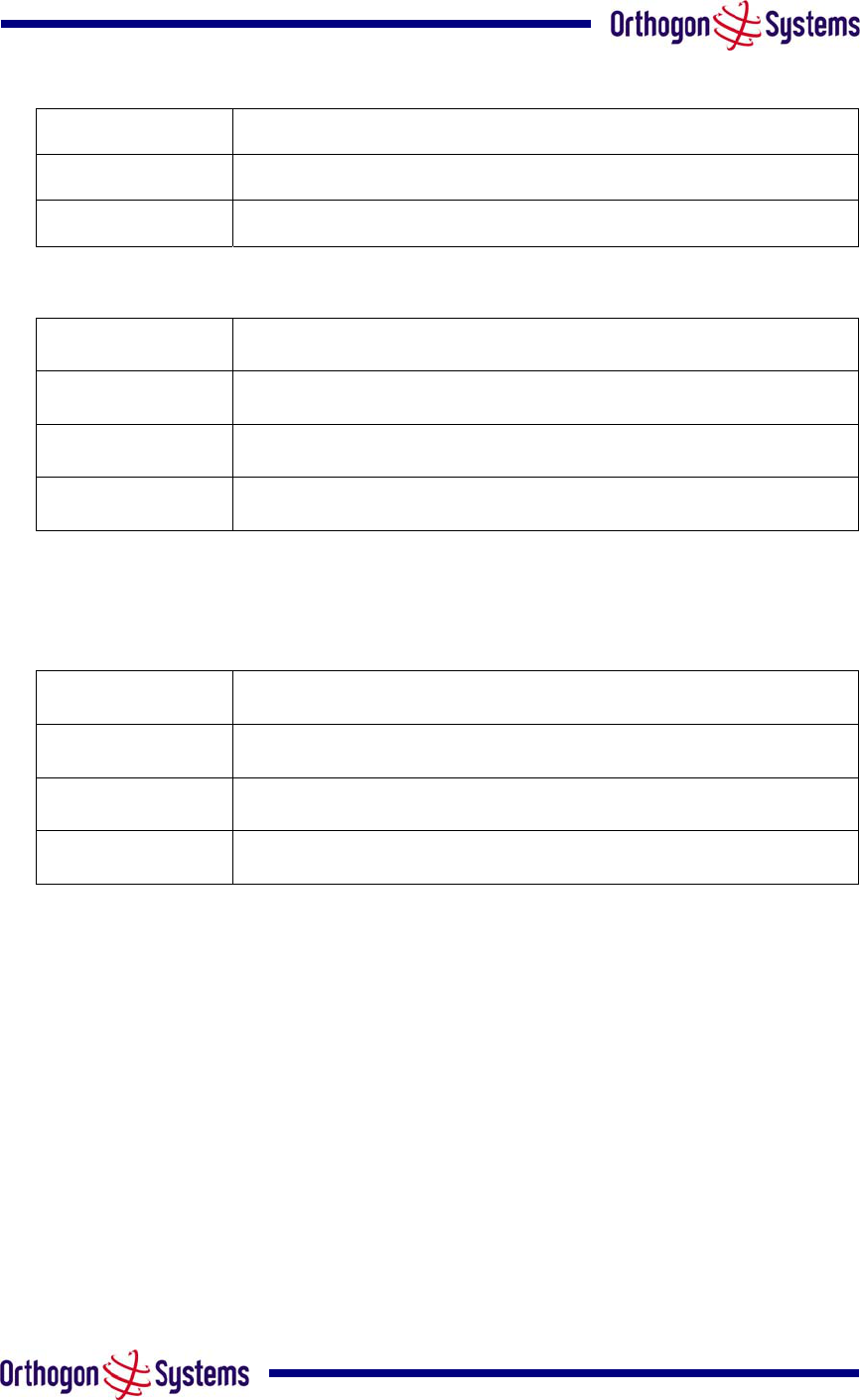
8.2 Safety Compliance
Region Specification
USA UL 60950
Canada CSA C22.2 No.60950
International CB certified & certificate to IEC 60950
8.3 EMC Emissions Compliance
Region Specification
USA FCC Part 15 Class B
Canada CSA Std C108.8, 1993 Class B
Europe EN55022 CISPR 22
77
8.4 EMC Immunity Compliance
Top-level Specification ETSI 301-489.
Specification Comment
EN 55082-1 Generic EMC and EMI
requirements for Europe
EN 61000-4-2: 1995 Electro Static Discharge
(ESD), Class 2, 8 kV air, 4 kV contact discharge
EN 61000-4-3: 1995 ENV50140: 1993 (radiated
immunity) 3 V/m
EN 61000-4-4: 1995 (Bursts/Transients), Class
4, 4 kV level (power lines AC & DC) Signal lines @ 0.5 kV open circuit
voltage.
EN 6100045:1995, (Surge Immunity) Requires screened connection to users
network
EN 61000-4-6: 1996 (Injected RF), power line,
Class 3 @ 10 V/m Signal lines, Class 3 @ 3 V RMS un-
modulated.
8.5 Radio Certifications
Region Specification (Type Approvals)
USA FCC Part 15.247
8.6 Environmental Specifications
Category Specification
Temperature ODU: -40°F(-40°C) to 140°F (+60°C)
IDU & PSU: 32°F(0°C) to 104oF(+40°C)
Wind Loading 151mph Max (242kph)
Humidity 100% Condensing
Waterproof IP65 (ODU) , IP53 (IDU)
UV Exposure 10 year operational life (UL746C test evidence)
78
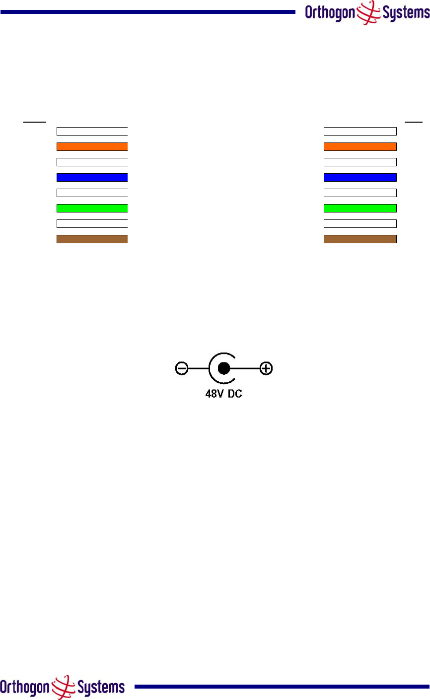
8.7 System Connections
8.7.1 ODU to IDU Connection
Pin 1
Pin 2
Pin 3
Pin 4
Pin 5
Pin 6
Pin 7
Pin 8
Pin 1
Pin 2
Pin 3
Pin 4
Pin 5
Pin 6
Pin 7
Pin 8
ODU IDU
Tx+ from ODU (White/Orange)
Tx- from ODU (Orange)
Rx+ to ODU (White/Green)
LED+ from ODU (Blue)
LED- from ODU (White/Blue)
Rx- to ODU (Green)
0V to ODU – (White/Brown)
+48V to ODU – (Brown)
Figure 33 ODU to IDU Connection Diagram
8.7.2 Power Connection
The IDU power connection is via a standard 2.5 mm DC power socket.
Figure 34 DC Connector Diagram
The DC connection diagram is shown in Figure 34 for completeness. The OS-Gemini should
only be used with the supplied PSU. Failure to do so may invalidate the unit’s safety
compliance and could lead to a fire.

79
9 Lightning Protection
9.1 Overview
The idea of lightning protection is to protect structures, equipment and people against lightning
by conducting the lightning current to ground via a separate preferential solid path and by
reducing the electromagnetic field.
The following should be treated as a guide only, the actual degree of lightning protection
required depends on local conditions and weather patterns. Full details of lightning protection
methods and requirements can be found in the international standards IEC 61024-1 and IEC
61312-1, the National Electric Code ANSI/NFPA No. 70-1984 or section 54 of the Canadian
Electric Code.
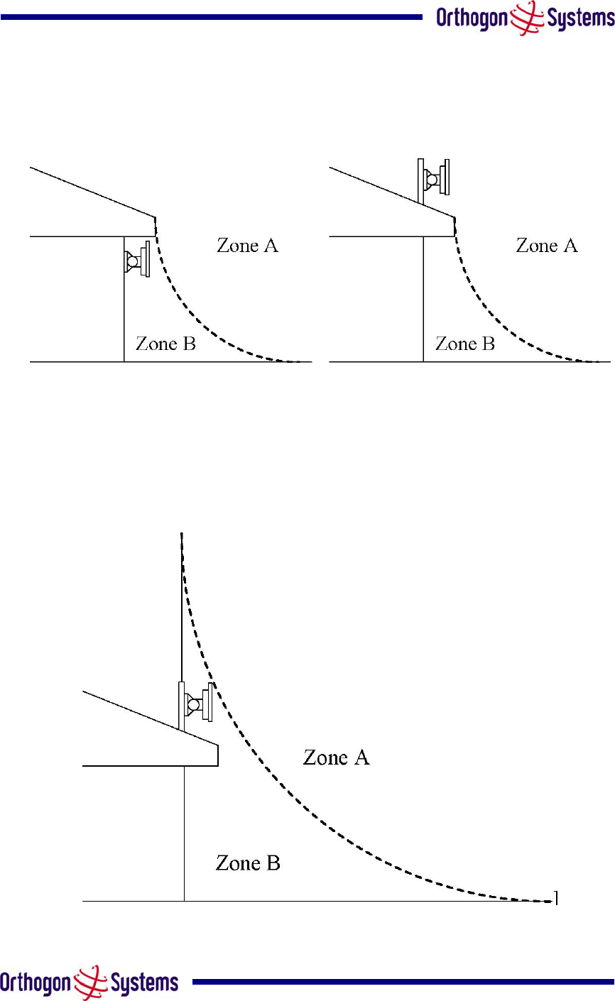
The installation of the ODU can be classified into two different lightning protection zones.
Zone A — In this zone a direct hit is possible.
Zone B — In this zone a direct hit is not possible, but the unattenuated electromagnetic field is
still present.
The next diagrams (Figure 35) show this zoning pictorially:
Equipment mounted in Zone A should be capable of carrying the full lightning current. Mounting
of the ODU in Zone A is not recommended. Mounting in Zone A should only be carried out
observing the rules governing installations in Zone A. Failure to do so may put structures,
equipment and life at risk.
Equipment mounted in Zone B should be grounded using grounding wire of at least 10 AWG.
This grounding wire should be connected to a grounding rod or the building grounding system
before entry in to building.
The OS-Gemini ODU grounding point can be found on the bottom of the unit. The OS-Gemini
is supplied with an appropriate grounding lug for attachment to the ODU.
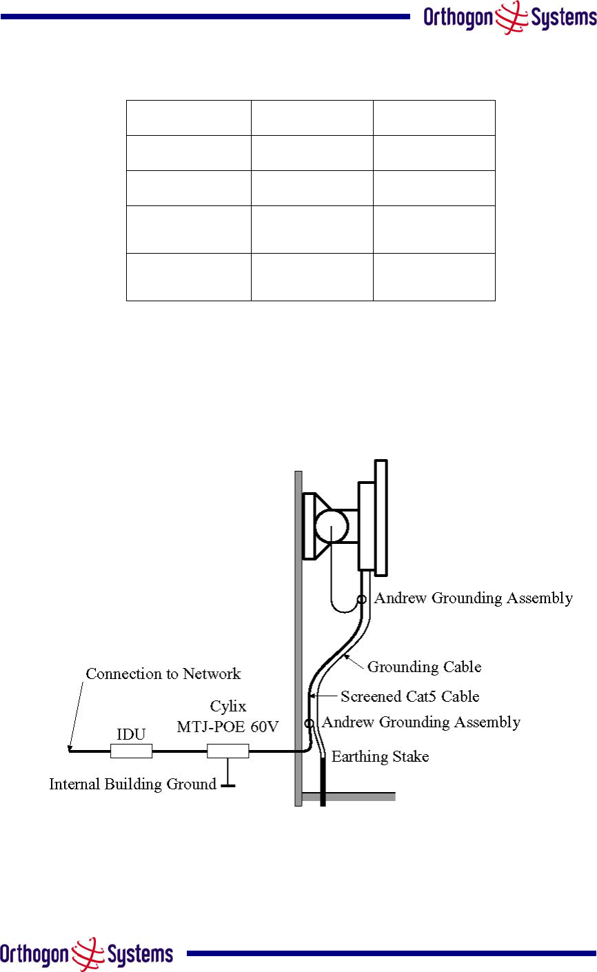
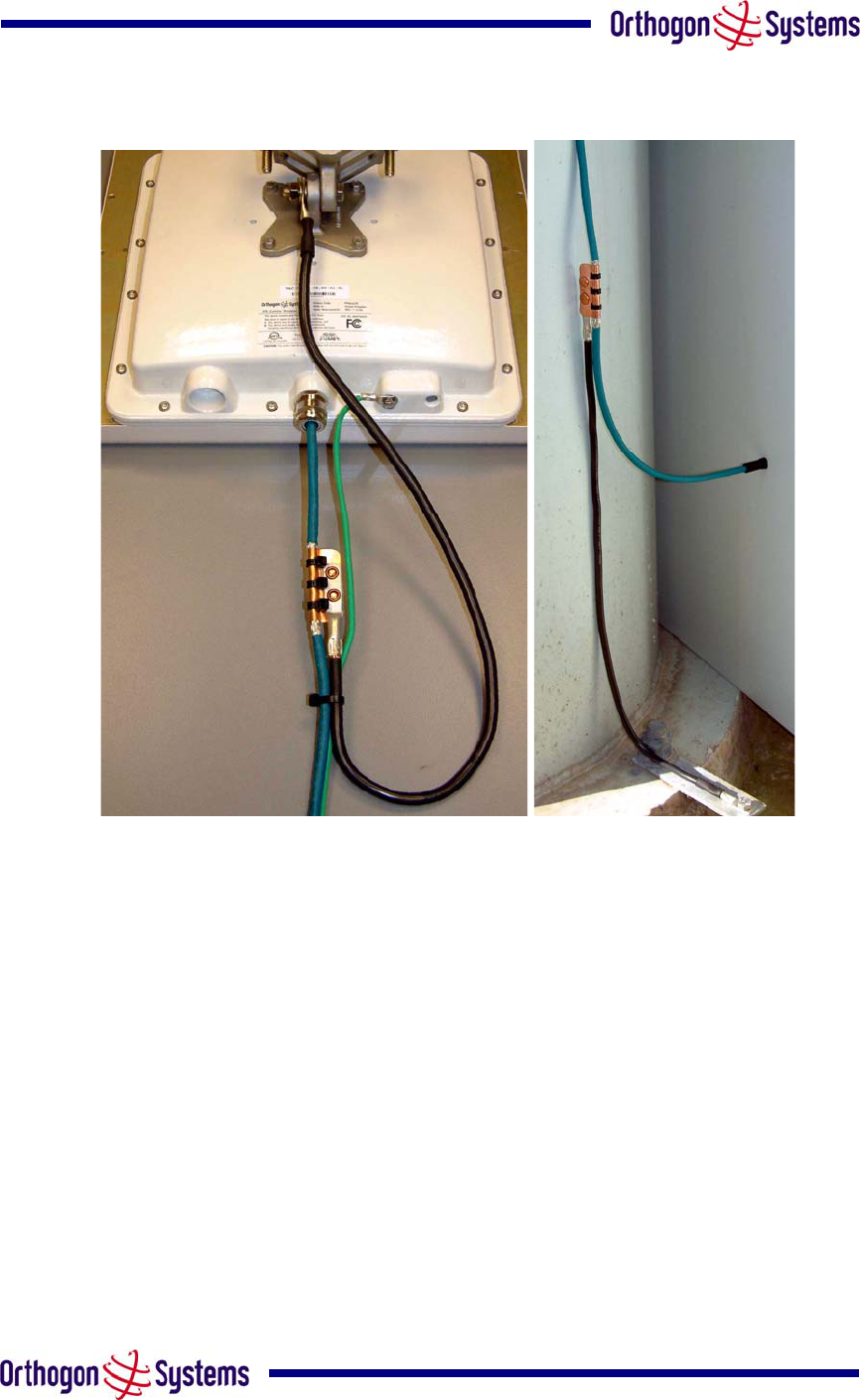
9.2 Detailed Installation
The recommended components for an installation protected for nearby strikes are:
• 2 Andrew Grounding Kits — Type 223158
• Screened Cat 5 Cable
• Line Protection Unit — Cyclix MTJ-POE 60V
• Grounding Stake
• 2 RJ45 connectors
• 10 AWG Grounding Cable
80
Figure 35 ODU Mounted in Zone B & ODU Mounted in Zone A
Figure 36 ODU mounted inside Zone B
81
Zone A Zone B
Earth ODU Mandatory Recommended
Screen Cable Mandatory Recommended
Earth Cable at
Building Entry Mandatory Recommended
Ethernet Surge
Arrestor Recommended Recommended
Table 8 Protection Requirements
Figure 37 Diagrammatically showing a typical installation
82
Figure 38 Upper Configuration and Lower Configuration
83
10 OS-Gemini C
10.1 Scope
This Chapter details the changes and additional features relevant to the connectorised variant
of the OS-Gemini C Product, OS 58XXC.
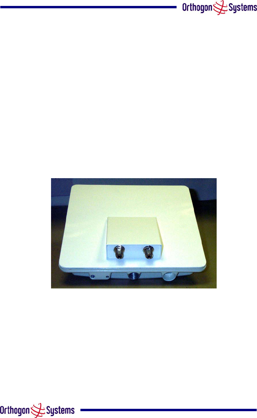
10.2 Product Description
10.2.1 Hardware
The OS-Gemini C is a variant designed to provide the system integrator and installer with the
ability to provide extra capability to cope with very difficult radio links compared to the basic
OS-Gemini product. The variant allows the use of a variety of externally mounted antennas,
either Flat Plate or Dish, which have higher gains than provided by the integrated antenna that
is normally used.
Figure 39 OS-Gemini C Outdoor Unit
10.2.2 Antenna Choices
The integrated antenna has a gain of 23dBi. External antennas from the list in Table 10 can be
used with the OS-Gemini C. These are approved by the FCC for use with the product and are
basically constrained by the following limits:
• Single Polarisation Flat Plate Antennas – up to 28dBi per antenna
• Single/Dual Polarisation Parabolic Dish Antennas – up to 37.7dBi per
polarisation or antenna
All external antennas – cable loss between OS-Gemini C and the antenna ports must not be
less than 1.2dB
84
10.3 Software/Features
The variant operates in the same way as the basic OS-Gemini product and is released initially
with the feature set of the OS-Gemini C product. The areas where the functionality is modified
are
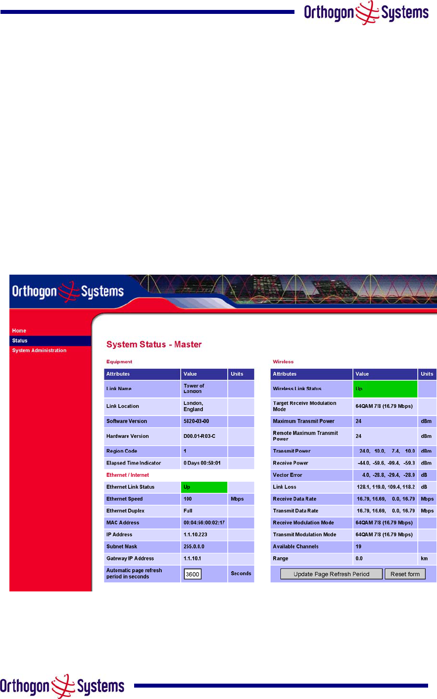
10.3.1 Status Page
The link loss calculation presented on the Status Page on the management interface has to be
modified to allow for the increased antenna gains at each end of the link. The manufacturing
process of the OS-Gemini C configures the standard hardware of the unit for use with external
antennas. The installer is prompted, as part of the installation process, to enter the gain of the
external antenna(s) and cable losses at each end of the link. Peer-2-Peer messaging is used to
pass the effective antenna gain to each end of the link so that the link loss calculations can be
correctly computed.
Figure 40 OS-Gemini C Status Page
86
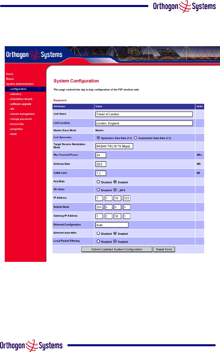
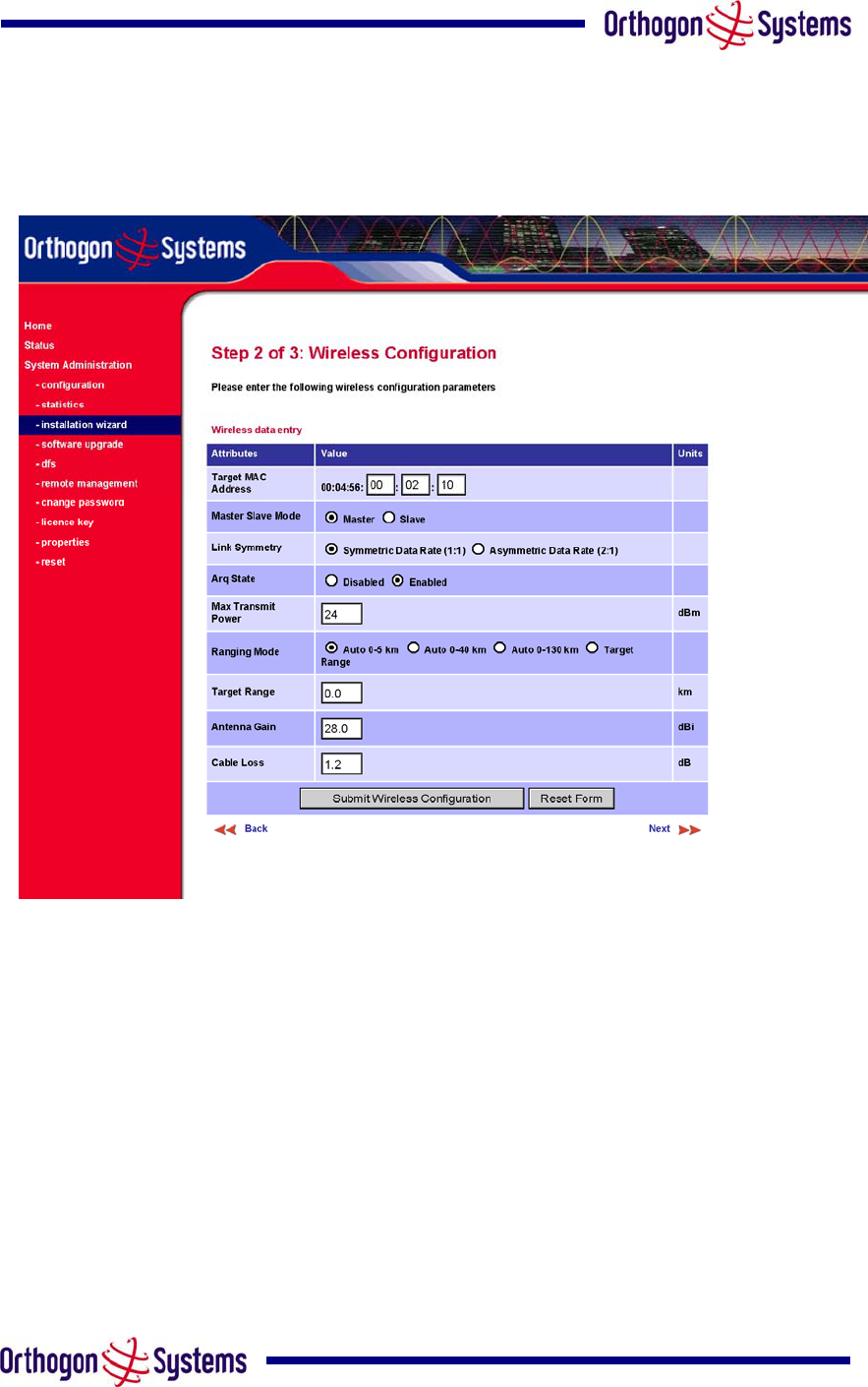
10.3.3 Installation Pages
The installer is prompted to enter the Antenna Gain and Cable Loss (OS-Gemini C to antenna)
at each end of the link. The Installation Page(s) is shown as Figure 42-Figure 44.
Figure 42 OS-Gemini C ‘Installation Wizard’ Page
Antenna Gain Gain of the antenna you are connecting to the unit, see Table 11 Allowed
Antennas for Deployment in USA/Canada.
Cable Loss Loss in the cable between the ODU and the antenna. Note: In the event that there
is a significant difference in length of the antenna cables for the two antenna ports, then the
average value should be entered.
87
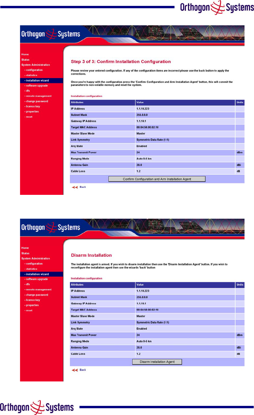
Figure 43 OS-Gemini C ‘Confirm Installation’ Page
Figure 44 OS-Gemini C ‘Disarm Installation’ Page
88
10.4 Deployment Considerations
The majority of radio links can be successfully deployed with the OS-Gemini product. It should
only be necessary to use external antennas where the Link Budget Calculator indicates
marginal performance for a specific link. Examples of this would be where the link is heavily
obscured by dense woodland on an NLOS link or extremely long LOS links (>80km) over
water.
The external antennas can be either dual-polarisation (as the integrated antenna) or two single
polarised antennas can be used in a spatially diverse configuration. It is expected that the
dual-polarisation antennas would normally be used to simplify the installation process; spatially
diverse antennas may provide additional fade margin on very long LOS links where there is
evidence of correlation of the fading characteristics on Vertical and Horizontal polarisations.
Dual polarisation antennas (with a gain greater than the integrated antenna) are currently only
available in parabolic dish form.
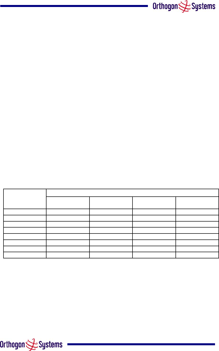
10.5 Link Budget
This is increased by the additional gain of the external antenna(s) less the cable losses. The
improvement in link budget is indicated in for a sample of the antennas when operating in
BPSK 1/2 and 64QAM 7/8 modes.
Integrated
Antenna
28dBi Flat Plate 4 ft Parabolic
Dish
6ft Parabolic
Dish
BPSK ½ 166.5 173.1 185.9 192.5
QPSK ½ 162.8 169.4 182.2 188.8
QPSK 2/3 160.7 167.3 180.1 186.7
16QAM ½ 156.1 162.7 175.5 182.1
16QAM ¾ 151.6 158.2 171.0 177.6
64QAM 2/3 146.2 152.8 165.6 172.2
64QAM ¾ 144.3 150.9 163.7 170.3
64QAM 7/8 139.6 146.2 159.0 165.6
Note: Gains are 23.5/28/34.4/37.7dBi and Cable Loss is 1.2dB for the External Antennas
Operating Mode
Static Link Budget (dB)
Table 9 Static Link Budget for Various Antenna Options

89
10.6 Regulatory Issues
In countries where FCC regulations are not relevant, installations should conform to any
applicable local regulations for the Equivalent Isotropic Radiated Power (EIRP).
Products deployed in North America or where FCC Part 15 regulations are used for unlicensed
radio equipments, the sections 10.6.1and 10.6.2 apply.
10.6.1 Antenna Choice
The antennas allowed to be deployed with the OS-Gemini C are shown inTable 11.
10.6.2 Cable Losses
The FCC approval for the product is based on tests with a cable loss between the units of
1.2dB at 5.8GHz. The use of lower cable losses would result in the installation being outside
the FCC rules.
As an indication, 1.2dB of cable loss corresponds to the following cable lengths excluding
connector losses (source: Times Microwave).
Length for 1.2dB Cable Loss at 5.8GHz
Cable (ft) (m)
LMR100 1.9 0.6
LMR200 4.6 1.4
LMR300 7.25 2.2
LMR400 11.1 3.4
Table 10 Cable Losses per Length

90
10.7 Antennas for USA / Canada
tennas for Deployment in USA/Canada
Manufacture
r
Antenna Type Gain (dBi) Flat Plate Parabolic Dis
h
Andre
w
Andrew 1-foot Flat Panel, FPA5250D12-N (23.6dBi) 23.6
Y
Andre
w
Andrew 2-foot Flat Panel, FPA5250D24-N (28dBi) 2
8
Y
Gabriel Gabriel 1-foot Flat Panel, DFPD1-52 (23.5dBi) 23.5
Y
Gabriel Gabriel 2-foot Flat Panel, DFPD2-52 (28dBi) 2
8
Y
MTI MTI 17 inch Diamond Flat Panel, MT-485009 (23dBi) 2
3
Y
MTI MTI 15 inch Dual-Pol Flat Panel, MT-485025/NVH (23dBi) 2
3
Y
MTI MTI 2 ft Directional Flat Panel, MT-20004 (28dBi) 2
8
Y
MTI MTI 2 ft Flat Panel, MT-486001 (28dBi) 2
8
Y
RFS RFS 1-foot Flat Panel, MA0528-23AN (23dBi) 2
3
Y
RFS RFS 2-foot Flat Panel, MA0528-28AN (28dBi) 2
8
Y
Telectronic
s
Teletronics 2-foot Flat Plate Antenna, ANT-P5828 (28dBi) 2
8
Y
Andre
w
Andrew 2-foot Parabolic, P2F-52 (29.4dBi) 29.4
Y
Andre
w
Andrew 2-foot Dual-Pol Parabolic, PX2F-52 (29.4dBi) 29.4
Y
Andre
w
Andrew 3-foot Parabolic, P3F-52 (33.4dBi) 33.4
Y
Andre
w
Andrew 3-foot Dual-Pol Parabolic, PX3F-52 (33.4dBi) 33.4
Y
Andre
w
Andrew 4-foot Parabolic, P4F-52 (34.9dBi) 34.9
Y
Andre
w
Andrew 4-foot Dual-Pol Parabolic, PX4F-52 (34.9dBi) 34.9
Y
Andre
w
Andrew 6-foot Parabolic, P6F-52 (37.6dBi) 37.6
Y
Andre
w
Andrew 6-foot Dual-Pol Parabolic, PX6F-52 (37.6dBi) 37.6
Y
Gabriel Gabriel 2-foot High Performance QuickFire Parabolic, HQF2-52-N 28.2
Y
Gabriel Gabriel 4-foot High Performance QuickFire Parabolic, HQF4-52-N 34.4
Y
Gabriel Gabriel 6-foot High Performance QuickFire Parabolic, HQF6-52-N 37.4
Y
Gabriel Gabriel 2-foot High Performance Dual QuickFire Parabolic, HQFD2-52-N 28.1
Y
Gabriel Gabriel 4-foot High Performance Dual QuickFire Parabolic, HQFD4-52-N 34.3
Y
Gabriel Gabriel 6-foot High Performance Dual QuickFire Parabolic, HQFD6-52-N 37.3
Y
Gabriel Gabriel 2-foot Standard QuickFire Parabolic, QF2-52-N 28.5
Y
Gabriel Gabriel 2-foot Standard QuickFire Parabolic, QF2-52-N-R
K
28.5
Y
Gabriel Gabriel 2.5-foot Standard QuickFire Parabolic, QF2.5-52-N 31.2
Y
Gabriel Gabriel 4-foot Standard QuickFire Parabolic, QF4-52-N 34.8
Y
Gabriel Gabriel 4-foot Standard QuickFire Parabolic, QF4-52-N-R
K
34.8
Y
Gabriel Gabriel 6-foot Standard QuickFire Parabolic, QF6-52-N 37.7
Y
Gabriel Gabriel 2-foot Standard Dual QuickFire Parabolic, QFD2-52-N 28.4
Y
Gabriel Gabriel 2.5-foot Standard Dual QuickFire Parabolic, QFD2.5-52-N 31.1
Y
Gabriel Gabriel 2-foot Standard Dual QuickFire Parabolic, QFD2-52-N-R
K
28.4
Y
Gabriel Gabriel 4-foot Standard Dual QuickFire Parabolic, QFD4-52-N 34.7
Y
Gabriel Gabriel 4-foot Standard Dual QuickFire Parabolic, QFD4-52-N-R
K
34.7
Y
Gabriel Gabriel 6-foot Standard Dual QuickFire Parabolic, QFD6-52-N 37.7
Y
RadioWave
s
Radio Waves 2-foot Dual-Pol Parabolic, SPD2-5.2 (28.1dBi) 28.1
Y
RadioWave
s
Radio Waves 2-foot Parabolic, SP2-5.2 (29.0dBi) 2
9
Y
RadioWave
s
Radio Waves 3-foot Dual-Pol Parabolic, SPD3-5.2 (31.1dBi) 31.1
Y
RadioWave
s
Radio Waves 3-foot Parabolic, SP3-5.2 (31.4dBi) 31.4
Y
RadioWave
s
Radio Waves 4-foot Dual-Pol Parabolic, SPD4-5.2 (34.4dBi) 34.4
Y
RadioWave
s
Radio Waves 4-foot Parabolic, SP4-5.2 (34.8dBi) 34.8
Y
RadioWave
s
Radio Waves 6-foot Dual-Pol Parabolic, SPD6-5.2 (37.5dBi) 37.5
Y
RadioWave
s
Radio Waves 6-foot Parabolic, SP6-5.2 (37.7dBi) 37.7
Y
RadioWave
s
Radio Waves 2-foot Parabolic, SP2-2/5 (28.3dBi) 28.3
Y
RadioWave
s
Radio Waves 3-foot Parabolic, SP3-2/5 (31.4dBi) 31.4
Y
RadioWave
s
Radio Waves 4-foot Parabolic, SP4-2/5 (34.6dBi) 34.6
Y
RadioWave
s
Radio Waves 6-foot Parabolic, SP6-2/5 (37.7dBi) 37.7
Y
RFS RFS 2-foot Parabolic, SPF2-52AN or SPFX2-52AN (27.9dBi) 27.9
Y
RFS RFS 3-foot Parabolic, SPF3-52AN or SPFX3-52AN(31.4dBi) 31.4
Y
RFS RFS 4-foot Parabolic, SPF4-52AN or SPFX4-52AN(33.9dBi) 33.9
Y
RFS RFS 6-foot Parabolic, SPF6-52AN or SPFX6-52AN (37.4dBi) 37.4
Y
RFS RFS 2-foot HP Parabolic, SDF2-52AN or SDFX2-52AN (31.4dBi) 31.4
Y
RFS RFS 4-foot HP Parabolic, SDF4-52AN or SDFX4-52AN (33.9dBi) 33.9
Y
RFS RFS 6-foot HP Parabolic, SDF6-52AN or SDFX6-52AN (37.4dBi) 37.4
Y
StellaDoradus StellaDoradus 45 inch Parabolic Antenna, 58PSD11
3
33.8
Y
Table 11 Allowed An

91
11 FAQs
The 100Base-T Ethernet Specification specifies a maximum cable length of 100m. Why
am I restricted to 60m of cable between the IDU and ODU? The 60m restriction is a result of
the voltage drop experienced using CAT 5 cable. The 100m maximum length still applies
between the ODU and connected equipment.
Can I source and use my own PoE adaptor with the OS-Gemini? No. The OS-Gemini uses
a non-standard PoE configuration. Failure to use the Orthogon Systems supplied IDU and
inline power supply could result in equipment damage and will invalidate the safety certification
and may cause a safety hazard.
Who are Orthogon Systems? Orthogon Systems are a specialist wireless manufacturer with
a high quality engineering team that is developing advanced radio solutions that allows high
capacity building-to-building bridges to be established even in deep non-Line-of-Sight
conditions.
Why have Orthogon Systems launched the OS-Gemini? The OS-Gemini is the first product
in this band to feature Multi-beam Space Time Coding. The OS-Gemini allows wireless
connections of up to 130km (81 miles) in near Line-of-Sight conditions and up to 10km (6
miles) in deep non-Line-of-Sight conditions.
What is Multi-beam Space-Time-Coding? The OS-Gemini radiates multiple beams from the
antenna - the effect of which is to significantly protect against fading and to radically increase
the probability that the receiver will decode a usable signal. When the effects of
Space-Time-Coding are combined with those of OFDM techniques and a best in class link
budget, there is a significant improvement to the probability of a robust connection over a
non-Line-of-Sight path.
What do you mean by “non-Line-of-Sight”? A wireless connection between 2 points without
optical Line-of-Sight. i.e. with obstructions in between the antennas but the transmitted signal is
still able to reach the receiver and produce a good quality link.
What else is special about the OS-Gemini? There are many special features built-in to the
hardware of the OS-Gemini. The product offers the highest system gain in its class through
high sensitivity antennae for improved signal recovery. It also features a Software Defined
Radio system that operates on ultra fast digital signal processors but is controlled by firmware
giving the ability to download new firmware when enhancements become available. The OS-
Gemini has a built-in web server for advanced management capabilities including detailed
radio signal diagnosis.

92
In which
operates
frequency band does the OS-Gemini operate? The Orthogon Systems OS-Gemini
in the unlicensed ISM band at 5.725 - 5.850GHz. This means no license is required to
veral channels such that multiple systems can
1a radio signals and choose a clean channel
known as Transmit Power Control (TPC) to ensure that it only transmits sufficient
usly monitors the spectrum to ensure it is
nsparent to higher-level management systems such as VLANs and
ed with the serial ID of its
operate the OS-Gemini.
Why does the OS-Gemini operate in the 5.8GHz ISM band? The 5.8GHz band offers the
dual benefits of high data throughput and good radio propagation characteristics. The wide
band of spectrum available is subdivided into se
operate in the vicinity without causing interference to one another.
Is the OS-Gemini an 802.11a device? No, although similar, the OS-Gemini uses different
encoding and radio transmission systems than 802.11a. In areas where 802.11a systems are
operating, the OS-Gemini will detect the 802.1
away from any interference.
How much power does the OS-Gemini transmit? At all times the OS-Gemini operates within
country / region specific regulations for radio power emissions. In addition, the OS-Gemini uses
a technique
radio power such that the other antenna can receive a high quality signal.
How does the OS-Gemini avoid interference from other devices nearby? At initialisation,
the OS-Gemini monitors the available frequency channels to find a channel that is clean from
interference. In operation OS-Gemini continuo
operating on the cleanest channel.
How does the OS-Gemini integrate into my data network? The OS-Gemini acts as a
transparent bridge between two segments of your network. In this sense, it can be treated like
a virtual wired connection between the two buildings. The OS-Gemini forwards 802.3 Ethernet
packets destined for the other part of the network and filters packets it does not need to
forward. The system is tra
Spanning Tree.
How does the OS-Gemini provide security for data traffic? The OS-Gemini has a range of
security features. At installation time each link must be programm
partner. The two ends of the link will only communicate with one another, eliminating any
chance of "man in the middle" attacks. Over the air security is achieved through a proprietary
scrambling mechanism that cannot be disabled, spoofed or snooped by commercial tools. If
further security is required the user is now able to optionally augment the existing high security
by encoding the air interface using AES.

93
How is the Advanced Encryption Standard (AES) enabled? The AES facility is enabled by
the user obtaining a licence key from Orthogon Systems. Entering the key will turn on the AES
options from which the user will be able to turn on AES. The default setting for AES is off.
ools. SNMP V1/V2 is also
hich could mislead the user.
How do I manage the OS-Gemini? The OS-Gemini has a built-in web server. At installation,
the unit is configured with an IP address so that the web server can then be accessed from any
browser equipped terminal. For security, access can be password protected, meaning only the
network administrator can access the web based management t
available and the unit can be configured to send traps or email notifications via SMTP.
Can I use Apple Macintosh OS X to control and monitor my OS-Gemini? Yes, but there
are some restrictions. Mozilla 1.6 is recommended. There are some issues with Internet
Explorer 5.2(IE) and Safari, w
How will my investment be protected as new features are developed? Future
enhancements can be downloaded to the unit, meaning advances in technology or changes in
regulations can quickly be applied to the system without any further hardware investment.

94
12 Glossary
AES
ARP
ARQ
BPSK
DC mputer
DFS
ETSI
Standards Institute PSU Power Supply Unit
FAQ
GPS
HTTP Hypertext Transfer Protocol RAM Random Access Memory
ID Identity STC Space Time Coding
IDU Indoor Unit STP Shielded Twisted Pair
IEEE Institute of Electrical and Electronic
Engineers TCP Transmission Control Protocol
IP Internet Protocol TPC Transmit Power Control
IQ In phase / Quadrature URL Universal Resource Location
ISM Industrial Scientific and Medical USA United States of America
ITU International Telecommunications
Union UTP Unshielded Twisted Pair
LAN Local Area Network UV Ultraviolet
MAC Medium Access Control Layer VLAN Virtual Local Area Network
MDI Medium Dependent Interface
MDIX Medium Dependent Interface
Crossover
Advanced Encryption Standard NLOS non-Line-of-Sight
Address Resolution Protocol ODU Outdoor Unit
Automatic Repeat reQuest OFDM Orthogonal Frequency Division
Binary Phase Shift Keying Multiplex
Direct Current PC IBM Compatible Personal Co
Dynamic Frequency Selection PING Packet INternet Groper
European Telecommunications POE Power over Ethernet
Frequently Asked Question PTP Point-to-Point
Global Positioning System QAM Quadrature Amplitude Modulation

95
13 Index
About This G
g the
na Ga 86
Not 32
State.........................................40, 48
ble Ch
Cha
able Loss..............................................86
and 1
e Sys 66
l Sp
e Word o ...........................43
liance ............. 1, 76, 77
ratio
figuring ..............44
firm Con ......49
cting
Contact Info
Copyright In n ...............................1
d Ins ..........79
onfig
easu
line
DFS Pages .............................................54
Disarm ....................................................50
ime .....................2
ance ..........................16
ic
Elapsed tor.....................32, 34
ectrica
ronm .........77
rnet ..............41
rnet ................40
ernet ........................34
rnet
rnet ......34
s.......................................................91
lt Fin ...........68
ng A 6
Your ..........6
quenc 16
Dupl ......34
Gateway .35, 40
General Considerations..........................16
tting S ................................6
sary ...94
Grounding The Installation .....................26
Half Duplex .............................................35
Hardware Version...................................34
Historic DFS Metrics...............................61
uide......................................6
Alignin ODUs ..................................29
Anten in..........................................
ARQ Is Configured...........................
ARQ
Availa annel...................................37
Barring nnels....................................59
C
Cables Connectors..........................1
Chang tem Administration Password
Channe ectrum Graphics ..................59
Cod Error Rati
Comp .....................
Configu n and Management .............12
Con The Wireless Units
Con figuration.......................
Conne Up........................................23
rmation ..................................7
formatio
Detaile tallation ......................
DFS C uration ..................................57
DFS M rements................................54
DFS On Help.....................................62
Discla r............................
Dist ........................
Dynam Frequency Selection................40
Time Indica
El l Requirements..........................17
Envi ental Specification ..........
Ethe Auto Mdix...................
Ethe Configuration............
Eth Duplex..............
Ethe Link Status ...............................34
Ethe Speed.................................
FAQ
Fau ding................................
Fitti Surge Arrestor..........................2
For Safety...............................
Fre y Planning................................
Full ex........................................
IP Address........................
Ge tarted..........
Glos ...............................................

96
Home Page.............................................31
tion...................................18
Mounting the ODUs................................22
Networking Information...........................16
IDU Site Selec
Install Pages ...........................................44
Install Status ...........................................32
Installation...............................................21
Installation Procedure.............................21
Installation Support.................................21
Internet Protocol Configuration...............45
IP Address ........................................35, 40
Lan Rx Packets.......................................43
Lan Tx Packets.......................................43
Legal Disclaimer .....................................22
Lightning Protection..........................16, 79
Link Location.....................................33, 39
Link Loss.................................................36
Link Name.................................. 31, 33, 39
Link Symmetry..................................39, 47
MAC Address..........................................35
Mains Power Adapter .............................11
Making the Connection At The IDU........26
Making the Connection At The ODU ......24
Master Slave Mode.................................47
Max Transmit Power...............................48
Maximum Transmit Power......................40
Measurement Analysis ...........................54
Mounting Brackets..................................12
Mounting The IDU...................................27
ODU Site Selection.................................18
ODU to IDU Connection .........................78
OS-Gemini C ..........................................83
Overview.................................................79
Packets From Internal Stack ..................43
Packets To Internal Stack.......................43
Path Loss Considerations.......................19
PHY Code Word Error Counter ..............43
Pole Mounting.........................................22
Power Connection ..................................78
Powering Up ...........................................28
Preparation .............................................21
Preparing The RJ45 ...............................23
Product Architecture ...............................14
Product Description ..................................7
Radio Certifications ................................77
Range .....................................................37
Ranging Mode ........................................48
Receive Data Rate ...........................36, 43
Receive Modulation Mode......................37
Receive Power........................................35
Refresh Page Period ............37, 57, 58, 59
Region Code...........................................34
Remote Management Page....................63
Remote Transmit Maximum Power ........35

97
Repair and Service ...................................7
Reset ......................................................66
Reset System Counters..........................43
Reset System Histograms ......................43
Routing the Cable...................................26
Site Planning...........................................18
Site Selection Criteria .............................18
SMTP (Simple Mail Transport Protocol).65
SMTP Destination Email Address ..........65
SMTP Email Alert ...................................65
SMTP IP Address ...................................65
SMTP Port Number ................................65
SMTP Source Email Address.................65
SNMP (Simple Network Management
Protocol)..............................................64
SNMP Community String........................64
SNMP Configuration...............................64
SNMP MIBs ............................................64
SNMP State......................................64, 65
SNMP Trap IP Address ..........................65
SNMP Trap Port Number .......................65
SNTP (Simple Network Time Protocol)..66
SNTP IP Address....................................66
SNTP Poll Interval ..................................66
SNTP Port Number.................................66
SNTP State.............................................66
SNTP Time Zone....................................66
Software Upgrade...................................51
Software Version ....................................34
Specifications..........................................72
Statistics Page........................................42
Statistics Page Refresh Period...............43
Subnet Mask.....................................35, 40
Surge Arrestor ........................................12
System Administration Pages.................38
System Clock..........................................32
System Configuration Page....................38
System Connections...............................78
System Specifications ............................72
Systems Status Page .............................32
Target MAC Address..............................47
Target Modulation Mode.........................35
Target Receive Modulation Mode...........39
The DFS Master / Slave Relationship ....55
The Indoor Unit (IDU) .............................10
The Outdoor Unit (ODU)...........................8
Tools Required .......................................21
Transmit Data Rate ..........................36, 43
Transmit Modulation Mode.....................37
Transmit Power.......................................35
Unit Calibration .......................................32
Vector Error ............................................36
Wall Mounting.........................................22
Wan Bad Rx Packets..............................42
Wan Dropped Tx Packets.......................42

Wan Good Rx Packets ...........................42
Wan Good Tx Packets............................42
Warranty .................................................13
Web Page Reference .............................31
Welcome...................................................6
Who Should Use This Guide ....................6
Wireless Channels..................................54
Wireless Configuration ...........................47
Wireless Link Availability ............43, 54, 55
Wireless Link Status .........................31, 35
98