Cambium Networks 5X250 Wireless Ethernet Bridge User Manual PTP 250
Cambium Networks Limited Wireless Ethernet Bridge PTP 250
PTP250 User Guide

Motorola B2B Collateral Branding UK Manual Cover insert A4 Text Field Template (02/10/07)
Sign o ........................................ date ................ Sht no 1 of 1 ag-UK-Manual Cover insert A4 Text Fields Template-00001-v02-ai-sw
Customer Documetation UK 2007
PTP 250
phn-2182_003v004
User Guide
System Release 250-02-00
Using this template follow these procedures.
1. Complete all the text fields using provided spreadsheet and specification information
2. Save file using appropriate naming title/convention in PDF format 2008 - 2010 Motorola, Inc. All Rights Reserved.
© 2011 Motorola Solutions, Inc. All Rights Reserved.

UNDER DEVELOPMENT phn-2182_003v004 (Oct 2011)
Accuracy
While reasonable efforts have been made to assure the accuracy of this document, Motorola Solutions, Inc. assumes no
liability resulting from any inaccuracies or omissions in this document, or from use of the information obtained herein.
Motorola Solutions, Inc. reserves the right to make changes to any products described herein to improve reliability,
function, or design, and reserves the right to revise this document and to make changes from time to time in content
hereof with no obligation to notify any person of revisions or changes. Motorola Solutions, Inc. does not assume any
liability arising out of the application or use of any product, software, or circuit described herein; neither does it convey
license under its patent rights or the rights of others. It is possible that this publication may contain references to, or
information about Motorola products (machines and programs), programming, or services that are not announced in your
country. Such references or information must not be construed to mean that Motorola intends to announce such Motorola
products, programming, or services in your country.
Copyrights
This document, Motorola products, and 3rd Party Software products described in this document may include or describe
copyrighted Motorola and other 3rd Party supplied computer programs stored in semiconductor memories or other media.
Laws in the United States and other countries preserve for Motorola, its licensors, and other 3rd Party supplied software
certain exclusive rights for copyrighted material, including the exclusive right to copy, reproduce in any form, distribute
and make derivative works of the copyrighted material. Accordingly, any copyrighted material of Motorola, its licensors,
or the 3rd Party software supplied material contained in the Motorola products described in this document may not be
copied, reproduced, reverse engineered, distributed, merged or modified in any manner without the express written
permission of Motorola. Furthermore, the purchase of Motorola products shall not be deemed to grant either directly or
by implication, estoppel, or otherwise, any license under the copyrights, patents or patent applications of Motorola or
other 3rd Party supplied software, except for the normal non-exclusive, royalty free license to use that arises by operation
of law in the sale of a product.
Restrictions
Software and documentation are copyrighted materials. Making unauthorized copies is prohibited by law. No part of the
software or documentation may be reproduced, transmitted, transcribed, stored in a retrieval system, or translated into
any language or computer language, in any form or by any means, without prior written permission of Motorola Solutions,
Inc.
License Agreements
The software described in this document is the property of Motorola Solutions, Inc. and its licensors. It is furnished by
express license agreement only and may be used only in accordance with the terms of such an agreement.
High Risk Materials
Components, units, or 3rd Party products used in the product described herein are NOT fault-tolerant and are NOT
designed, manufactured, or intended for use as on-line control equipment in the following hazardous environments
requiring fail-safe controls: the operation of Nuclear Facilities, Aircraft Navigation or Aircraft Communication Systems,
Air Traffic Control, Life Support, or Weapons Systems (High Risk Activities). Motorola and its supplier(s) specifically
disclaim any expressed or implied warranty of fitness for such High Risk Activities.
Trademarks
MOTOROLA and the Stylized M Logo are registered in the US Patent & Trademark Office. All other product or service
names are the property of their respective owners.

PTP 250 User Guide
phn-2182_003v004 (Oct 2011) UNDER DEVELOPMENT I
Safety and regulatory information
This section describes important safety and regulatory guidelines that must be observed by
personnel installing or operating PTP 250 equipment.
Important safety information
To prevent loss of life or physical injury, observe the safety guidelines in this
section.
Power lines
Exercise extreme care when installing antennas near power lines.
Working at heights
Exercise extreme care when working at heights.
Grounding and protective earth
The Outdoor Unit (ODU) must be properly grounded to protect against lightning. It is the
user’s responsibility to install the equipment in accordance with national regulations. In
the USA, follow Section 810 of the
National Electric Code, ANSI/NFPA No.70-1984
(USA).
In Canada, follow Section 54 of the
Canadian Electrical Code
. These codes describe
correct installation procedures for grounding the outdoor unit, mast, lead-in wire and
discharge unit, size of grounding conductors and connection requirements for grounding
electrodes. Other regulations may apply in different countries and therefore it is
recommended that installation of the outdoor unit be contracted to a professional installer.
Using the correct power supply
Always use the Motorola Power over Ethernet injector unit (PoE power supply) or Powered
Indoor Unit (PIDU Plus) to power the ODU. Failure to use the correct power supply could
result in equipment damage and will invalidate the safety certification and may cause a
safety hazard.

Safety and regulatory information
II UNDER DEVELOPMENT phn-2182_003v004 (Oct 2011)
Alternative DC supply
If the PTP 250 is to be powered from a DC supply (either as the primary power source or
as a backup to the AC supply), the DC supply must be input to the ODU via a PIDU (not a
PoE power supply). The DC supply must be connected to the PIDU DC IN terminals. The
DC supply must comply with the following requirements:
• The voltage and polarity is correct and is applied to the correct terminals in the PIDU.
• The power source is rated as Safety Extra Low Voltage (SELV).
• The power source is rated to supply at least 1 A continuously.
• The power source cannot provide more than the Energy Hazard Limit as defined by
IEC/EN/UL60950-1, Clause 2.5, Limited Power (The Energy Hazard Limit is 240VA).
Powering down before servicing
Always power down and unplug the equipment before servicing.
Lightning protection unit (LPU)
Do not remove the LPU printed circuit board when the LPU is connected to the power
supply, as high voltages are present.
Non-Motorola power supply
Safety may be compromised if a different power supply is used than the one supplied by
Motorola as part of the system.
Drop cable tester
The drop cable tester must NEVER be used at the ODU end connected to power from the
PoE power supply. It must only be used at the bottom of the mast with a multimeter. This
is because the PoE power supply voltage exceeds the limit allowed in some countries for
safe handling in wet conditions and therefore may create a safety hazard.
Primary disconnect device
The main power supply is the primary disconnect device.
External cables
Safety may be compromised if outdoor rated cables are not used for connections that will
be exposed to the outdoor environment.

PTP 250 User Guide
phn-2182_003v004 (Oct 2011) UNDER DEVELOPMENT III
RF exposure near the antenna
Strong radio frequency (RF) fields will be present close to the antenna when the
transmitter is on. Always turn off the power to the ODU before undertaking maintenance
activities in front of the antenna.
Minimum separation distances
Install the ODUs so as to provide and maintain the minimum separation distances from all
persons.
The minimum separation distances for each frequency variant are specified in Calculated
distances and power compliance margins on page 4-10.
Important regulatory information
Operation of the PTP 250 product involves its use as an unlicensed device in frequency
bands where it is not allowed to cause interference to licensed services (called primary
users of the bands).
Radar avoidance
In some countries radar systems are the primary users and the regulators have devised
special requirements to protect their operation from interference caused by unlicensed
devices. The unlicensed devices are required to detect the presence of radar systems and
avoid co-channel operation with the radar systems.
The PTP 250 system provides detection and avoidance functionality for countries and
frequency bands requiring protection for radar systems.
Installers and users are reminded that they must follow local regulations with regard to
any requirements for radar detection as well as transmitted power level. This can be
achieved by using the correct country code for the product concerned. Failure to follow
this could leave the installer and/or user liable to civil and/or criminal penalties.
Contact the Motorola helpdesk if you are unsure about any specific areas where you need
guidance.

Safety and regulatory information
IV UNDER DEVELOPMENT phn-2182_003v004 (Oct 2011)
USA specific information
The USA Federal Communications Commission (FCC) has asked manufacturers to
implement special features to prevent interference to weather radar systems that operate
in the band 5600 MHz to 5650 MHz. These features must be implemented in all products
able to operate outdoors in the band 5470 MHz to 5725 MHz.
Manufacturers must ensure that such radio products cannot be configured to operate
outside of FCC rules; specifically it must not be possible to disable or modify the radar
protection functions that have been demonstrated to the FCC.
In order to comply with these clear FCC requirements for all manufacturers, Motorola is
releasing variants of PTP 250 for USA or Canada operation. These new devices will only
be allowed to operate in accordance with FCC/IC rules. In particular, operation of radio
channels overlapping the band 5600-5650 MHz is not allowed and these are permanently
barred in the products offered for sale in the USA/Canada.
Other versions of the products will be available for use in the rest of the world, but these
versions will not be supplied to the USA except under strict controls, when they are
needed for export and deployment outside the USA.
To ensure compliance with FCC rules (
KDB 443999: Interim Plans to Approve UNII
Devices Operating in the 5470 - 5725 MHz Band with Radar Detection and DFS
Capabilities
), follow the instructions in Avoidance of weather radars (USA only) on page 2-
5.

PTP 250 User Guide
phn-2182_003v004 (Oct 2011) UNDER DEVELOPMENT i
Contents
PTP 250 ........................................................................................................................... 1
Safety and regulatory information .................................................................................... I
Important safety information .................................................................................................. I
Important regulatory information ........................................................................................ III
About This User Guide ..................................................................................................... 1
Revision history ............................................................................................................................ 2
General information ..................................................................................................................... 3
Contacting Motorola .................................................................................................................... 4
Reporting problems ................................................................................................................ 5
Security advice ............................................................................................................................. 7
Warnings, cautions, and notes ..................................................................................................... 8
Caring for the environment .......................................................................................................... 9
Chapter 1:Product description .................................................................................. 1-1
Overview of the PTP 250 ........................................................................................................... 1-2
Purpose ............................................................................................................................... 1-2
Key features ........................................................................................................................ 1-2
Typical deployment ............................................................................................................. 1-3
System components ............................................................................................................ 1-3
Product variants .................................................................................................................. 1-4
Outdoor unit (ODU) .................................................................................................................. 1-5
ODU description .................................................................................................................. 1-5
ODU interfaces .................................................................................................................... 1-6
Connectorized ODU antenna interfaces .............................................................................. 1-7
Mounting brackets .............................................................................................................. 1-7
Network connection ............................................................................................................ 1-7
Further reading on the ODU ............................................................................................... 1-8
Power over Ethernet injector (PoE power supply) .................................................................... 1-9
PoE power supply description ............................................................................................. 1-9
PoE features ...................................................................................................................... 1-10
PoE power supply interfaces ............................................................................................. 1-10
Further reading on the PoE power supply ........................................................................ 1-12
Cabling and lightning protection ............................................................................................ 1-13

Contents
ii UNDER DEVELOPMENT phn-2182_003v004 (Oct 2011)
PTP and lightning protection ............................................................................................ 1-13
Outdoor connections ......................................................................................................... 1-13
Indoor connections ............................................................................................................ 1-14
Cable grounding kits ......................................................................................................... 1-14
Lightning protection units (LPUs) .................................................................................... 1-15
Further reading on cabling and lightning protection ....................................................... 1-16
Wireless operation .................................................................................................................. 1-17
Wireless Transmissions ..................................................................................................... 1-17
Spectrum management ..................................................................................................... 1-17
Adaptive modulation ......................................................................................................... 1-17
MIMO ................................................................................................................................ 1-18
Radar avoidance ................................................................................................................ 1-19
Security ............................................................................................................................. 1-20
Country of operation ......................................................................................................... 1-20
Using frequency planning ................................................................................................. 1-21
Further reading on wireless operation ............................................................................. 1-22
Ethernet bridging .................................................................................................................... 1-23
Customer network ............................................................................................................. 1-23
Management network ....................................................................................................... 1-24
Back-to-back links ............................................................................................................. 1-24
Protocol model .................................................................................................................. 1-25
Further reading on Ethernet bridging .............................................................................. 1-26
System management ............................................................................................................... 1-27
Web server ........................................................................................................................ 1-27
Firmware upgrade ............................................................................................................ 1-28
Reset to factory defaults ................................................................................................... 1-28
Further reading on system management .......................................................................... 1-28
Chapter 2:Planning considerations ........................................................................... 2-1
Regulatory planning .................................................................................................................. 2-2
Regulatory limits ................................................................................................................. 2-2
Conforming to the limits ..................................................................................................... 2-3
Available spectrum .............................................................................................................. 2-3
Frequency selection ............................................................................................................ 2-4
Channel width ..................................................................................................................... 2-4
Avoidance of weather radars (USA only) ............................................................................ 2-5
Site planning ............................................................................................................................. 2-6
ODU site selection .............................................................................................................. 2-6

PTP 250 User Guide
phn-2182_003v004 (Oct 2011) UNDER DEVELOPMENT iii
Power supply selection ........................................................................................................ 2-6
Maximum cable lengths ...................................................................................................... 2-7
Wind loading ....................................................................................................................... 2-7
Link planning .......................................................................................................................... 2-10
Range and obstacles ......................................................................................................... 2-10
PTP LINKPlanner .............................................................................................................. 2-10
Path loss considerations .................................................................................................... 2-11
Planning for connectorized units ............................................................................................ 2-12
When to install connectorized units .................................................................................. 2-12
Choosing external antennas .............................................................................................. 2-12
Calculating maximum power level for connectorized units .............................................. 2-13
Calculating RF cable length (5.8 GHz FCC only) .............................................................. 2-14
Grounding and lightning protection ........................................................................................ 2-15
The need for power surge protection ................................................................................ 2-15
Standards .......................................................................................................................... 2-15
Lightning protection zones ............................................................................................... 2-16
General protection requirements ...................................................................................... 2-17
Protection requirements for a mast or tower installation ................................................. 2-18
Protection requirements for a wall installation ................................................................ 2-20
Protection requirements on a high rise building .............................................................. 2-21
Data network planning ............................................................................................................ 2-23
IP interface ........................................................................................................................ 2-23
Back to back links ............................................................................................................. 2-23
‘Green Ethernet’ switches ................................................................................................. 2-23
Ordering components.............................................................................................................. 2-24
PTP 250 kits ...................................................................................................................... 2-24
Other standard components .............................................................................................. 2-27
Components required with connectorized ODUs .............................................................. 2-29
Alternative components .................................................................................................... 2-34
Chapter 3:Legal information ..................................................................................... 3-1
Motorola Solutions, Inc. end user license agreement ............................................................... 3-2
Definitions ........................................................................................................................... 3-2
Grant of license ................................................................................................................... 3-2
Conditions of use ................................................................................................................. 3-3
Title and restrictions ........................................................................................................... 3-4
Confidentiality ..................................................................................................................... 3-4
Right to use Motorola’s name ............................................................................................. 3-5

Contents
iv UNDER DEVELOPMENT phn-2182_003v004 (Oct 2011)
Transfer ............................................................................................................................... 3-5
Updates ............................................................................................................................... 3-5
Maintenance ....................................................................................................................... 3-5
Disclaimer ........................................................................................................................... 3-6
Limitation of liability ........................................................................................................... 3-6
U.S. government ................................................................................................................. 3-6
Term of license .................................................................................................................... 3-7
Governing law ..................................................................................................................... 3-7
Assignment .......................................................................................................................... 3-7
Survival of provisions .......................................................................................................... 3-7
Entire agreement ................................................................................................................ 3-7
Third party software ........................................................................................................... 3-7
Hardware warranty ................................................................................................................... 3-9
Limit of liability ....................................................................................................................... 3-10
Chapter 4:Reference information .............................................................................. 4-1
Equipment specifications .......................................................................................................... 4-2
ODU specifications .............................................................................................................. 4-2
Power supply unit specifications ......................................................................................... 4-3
Wireless specifications .............................................................................................................. 4-5
General wireless specifications ........................................................................................... 4-5
Data network specifications ...................................................................................................... 4-7
Ethernet interfaces ............................................................................................................. 4-7
Compliance with safety standards ............................................................................................ 4-8
Electrical safety compliance ............................................................................................... 4-8
Electromagnetic compatibility (EMC) compliance ............................................................. 4-8
Human exposure to radio frequency energy ....................................................................... 4-9
Compliance with radio regulations ......................................................................................... 4-12
Type approvals .................................................................................................................. 4-12
FCC and ETSI compliance testing .................................................................................... 4-13
Notifications ............................................................................................................................ 4-14
5.4 GHz European Union notification ............................................................................... 4-14
5.8 GHz FCC and IC notification ....................................................................................... 4-15
5.8 GHz European Union notification ............................................................................... 4-16
Chapter 5:Installation .............................................................................................. 5-1
Preparing for installation .......................................................................................................... 5-2
Unit pre-configuration ........................................................................................................ 5-2
Safety precautions .............................................................................................................. 5-2

PTP 250 User Guide
phn-2182_003v004 (Oct 2011) UNDER DEVELOPMENT v
Protection requirements ..................................................................................................... 5-2
Selecting installation options .............................................................................................. 5-3
Preparing personnel ............................................................................................................ 5-3
Preparing inventory ............................................................................................................ 5-3
Preparing tools .................................................................................................................... 5-3
Installing the ODU .................................................................................................................... 5-4
Checks and safety precautions ........................................................................................... 5-4
Selecting a position for the ODU (connectorized) .............................................................. 5-6
Mounting the ODU .............................................................................................................. 5-6
Installing connectorized antennas ............................................................................................ 5-8
Preparing for connectorized installations ........................................................................... 5-8
Mounting and connecting antennas .................................................................................... 5-8
Weatherproofing an N type connector .............................................................................. 5-12
Installing the drop cable and LPU .......................................................................................... 5-15
Preparing drop cables ....................................................................................................... 5-16
Assembling an RJ45 connector and gland ......................................................................... 5-17
Installing and grounding the main drop cable .................................................................. 5-19
Connecting an RJ45 and gland to a unit ........................................................................... 5-20
Disconnecting an RJ45 and gland from a unit .................................................................. 5-22
Making a drop cable ground point .................................................................................... 5-23
Installing and grounding the drop cable at building entry ............................................... 5-27
Installing the PoE power supply ............................................................................................. 5-29
Preparing for PoE power supply installation .................................................................... 5-29
Mounting the PoE power supply ....................................................................................... 5-30
Connecting the PoE power supply to the drop cable ........................................................ 5-31
Preparing the PoE power supply to network equipment cable ......................................... 5-32
Chapter 6:Configuration and alignment .................................................................... 6-1
Preparing for configuration and alignment .............................................................................. 6-2
Safety precautions during configuration and alignment .................................................... 6-2
Regulatory compliance during configuration and alignment .............................................. 6-2
Selecting configuration options .......................................................................................... 6-2
Connecting to the unit .............................................................................................................. 6-3
Configuring the management PC ........................................................................................ 6-3
Connecting to the PC and powering up .............................................................................. 6-5
Logging into the web interface ........................................................................................... 6-6
Upgrading firmware version ................................................................................................... 6-10
Checking the installed firmware version .......................................................................... 6-10

Contents
vi UNDER DEVELOPMENT phn-2182_003v004 (Oct 2011)
Uploading a new firmware version ................................................................................... 6-11
Using the installation wizard .................................................................................................. 6-13
Starting installation wizard ............................................................................................... 6-13
Step 1: LAN configuration ................................................................................................ 6-14
Step 2: Wireless configuration .......................................................................................... 6-16
Step 3: Date and time settings .......................................................................................... 6-18
Step 4: Email configuration .............................................................................................. 6-21
Step 5: Confirm installation configuration ........................................................................ 6-22
Aligning antennas ................................................................................................................... 6-23
Starting up the units ......................................................................................................... 6-23
Checking that the units are armed ................................................................................... 6-24
Aligning antennas ............................................................................................................. 6-24
Aligning separate antennas for spatial diversity .............................................................. 6-26
Monitoring received signal level ....................................................................................... 6-26
Disarming the units ........................................................................................................... 6-29
Connecting link to the network ............................................................................................... 6-30
Reviewing system configuration attributes ...................................................................... 6-30
Comparing actual to predicted performance .................................................................... 6-33
Connecting to the network................................................................................................ 6-34
Saving the system configuration ............................................................................................. 6-35
Saving the system configuration ....................................................................................... 6-35
Chapter 7:Operation ................................................................................................. 7-1
Web-based management ........................................................................................................... 7-2
Accessing the web interface ............................................................................................... 7-2
Using the menu options ...................................................................................................... 7-4
Viewing the system summary ............................................................................................. 7-6
Viewing the system status .................................................................................................. 7-8
Changing password ........................................................................................................... 7-14
Logging out ....................................................................................................................... 7-14
Managing link status and alerts .............................................................................................. 7-15
Managing link status ......................................................................................................... 7-15
Managing email alerts ...................................................................................................... 7-16
Managing performance ........................................................................................................... 7-17
Checking system statistics ................................................................................................ 7-17
Checking channel status ................................................................................................... 7-19
Checking the retry histogram ........................................................................................... 7-20
Using the diagnostics plotter ............................................................................................ 7-21

PTP 250 User Guide
phn-2182_003v004 (Oct 2011) UNDER DEVELOPMENT vii
Diagnostics calculated over time ...................................................................................... 7-23
Restoring, resetting and rebooting ......................................................................................... 7-24
Restoring the system configuration .................................................................................. 7-24
Resetting to default configuration (without country reset) .............................................. 7-25
Resetting to default configuration (with country reset) ................................................... 7-26
Recovering a lost IP address ............................................................................................. 7-28
Rebooting the unit ............................................................................................................. 7-28
Chapter 8:Troubleshooting ....................................................................................... 8-1
Testing link end hardware ........................................................................................................ 8-2
Testing when PoE LEDs do not illuminate correctly ........................................................... 8-2
Testing after a lightning strike ........................................................................................... 8-2
Test flowcharts .................................................................................................................... 8-3
AC LED is off ....................................................................................................................... 8-5
AC LED is flashing .............................................................................................................. 8-5
PORT LED is off .................................................................................................................. 8-6
PORT LED is flashing .......................................................................................................... 8-6
Test Ethernet packet errors reported by ODU ................................................................... 8-8
Test Ethernet packet errors reported by managed switch or router .................................. 8-8
Test ping packet loss ........................................................................................................... 8-9
Test resistance in the ODU cable ...................................................................................... 8-10
Testing the radio link .............................................................................................................. 8-12
No activity ......................................................................................................................... 8-12
Some activity ..................................................................................................................... 8-13
Radio and television interference ..................................................................................... 8-13
Glossary ........................................................................................................................... I

PTP 250 User Guide
phn-2182_003v004 (Oct 2011) UNDER DEVELOPMENT viii
List of Figures
Figure 1-1 Typical PTP 250 bridge deployment (grounding not shown) ....................................... 1-3
Figure 1-2 Integrated ODU (front and rear views) ....................................................................... 1-5
Figure 1-3 Connectorized ODU (front and rear views) ................................................................. 1-5
Figure 1-4 ODU interfaces ............................................................................................................ 1-6
Figure 1-5 Connectorized ODU antenna interfaces ...................................................................... 1-7
Figure 1-6 PoE power supply ........................................................................................................ 1-9
Figure 1-7 PoE power supply interfaces ..................................................................................... 1-10
Figure 1-8 Cable grounding kit for 1/4” and 3/8” cable .............................................................. 1-14
Figure 1-9 LPU kit ....................................................................................................................... 1-15
Figure 1-10 Protocol layers between Ethernet and wireless interfaces ..................................... 1-25
Figure 1-11 Protocol layers between external interfaces and the management agent .............. 1-26
Figure 2-1 Rolling sphere method to determine the lightning protection zones ........................ 2-16
Figure 2-2 Grounding cable minimum bend radius and angle .................................................... 2-18
Figure 2-3 Grounding and lightning protection on mast or tower .............................................. 2-19
Figure 2-4 Grounding and lightning protection on wall .............................................................. 2-20
Figure 2-5 Grounding and lightning protection on building ....................................................... 2-21
Figure 2-6 Grounding and lightning protection inside high building ......................................... 2-22
Figure 4-1 European Union certification on 5.4 GHz product label ........................................... 4-14
Figure 4-2 FCC and IC certifications on 5.8 GHz product label ................................................. 4-16
Figure 4-3 European Union certification on 5.8 GHz product label ........................................... 4-17
Figure 5-1 Checking the ODU before mounting ........................................................................... 5-5
Figure 5-2 Lightning arrestor mounting ....................................................................................... 5-9
Figure 5-3 Polyphaser assembly ................................................................................................. 5-10
Figure 5-4 Grounding points for antenna cables ........................................................................ 5-11
Figure 5-5 Typical hoisting grip on cable .................................................................................... 5-16
Figure 5-6 Correct cable preparation for drop cable of the supported type ............................... 5-18
Figure 5-7 Drop cable with RJ45 and gland ................................................................................ 5-19
Figure 5-8 Grounding at building entry ...................................................................................... 5-27
Figure 5-9 Mounting slots on underside of PoE power supply ................................................... 5-30
Figure 5-10 PoE power supply connected to LPU-PoE cable ...................................................... 5-31
Figure 6-1 IP configuration on the PC .......................................................................................... 6-4
Figure 6-2 Internet Protocol (TCP/IP) Properties page ................................................................. 6-4

PTP 250 User Guide
phn-2182_003v004 (Oct 2011) UNDER DEVELOPMENT ix
Figure 6-3 PoE power supply connected to ODU and PC (or network)......................................... 6-5
Figure 6-4 Digital signature confirmation (on first login) ............................................................. 6-7
Figure 6-5 Digitally signed Java app splash screen ....................................................................... 6-7
Figure 6-6 Login page ................................................................................................................... 6-8
Figure 6-7 Change Password page (on first login) ........................................................................ 6-8
Figure 6-8 Set Country Code page (on first login) ........................................................................ 6-9
Figure 6-9 Menu and System Summary page (on first login) ....................................................... 6-9
Figure 6-10 Firmware Version in System Status page ................................................................ 6-10
Figure 6-11 Firmware Update page ............................................................................................ 6-12
Figure 6-12 Upload Successful page ........................................................................................... 6-12
Figure 6-13 Step 5: Confirm Configuration page (when unit is armed) ...................................... 6-13
Figure 6-14 Step 1: LAN Configuration page .............................................................................. 6-14
Figure 6-15 Step 2: Wireless Configuration page ....................................................................... 6-16
Figure 6-16 Step 3: Date and Time Settings page ...................................................................... 6-19
Figure 6-17 Step 4: Email Configuration page ............................................................................ 6-21
Figure 6-18 Step 5: Confirm Configuration page ........................................................................ 6-22
Figure 6-19 System Summary page (when unit is armed) .......................................................... 6-24
Figure 6-20 Graphical Alignment page ....................................................................................... 6-28
Figure 6-21 System Configuration page ...................................................................................... 6-31
Figure 6-22 LAN Configuration page .......................................................................................... 6-31
Figure 6-23 Date and Time Settings page ................................................................................... 6-32
Figure 6-24 System Status page ................................................................................................. 6-33
Figure 6-25 Save & Restore page ............................................................................................... 6-35
Figure 7-1 Login page ................................................................................................................... 7-2
Figure 7-2 Menu and System Summary page (wireless link up) ................................................... 7-3
Figure 7-3 Menu navigation bar .................................................................................................... 7-4
Figure 7-4 System Summary page ................................................................................................ 7-6
Figure 7-5 System Status page ..................................................................................................... 7-8
Figure 7-6 Change Password page .............................................................................................. 7-14
Figure 7-7 Status warning triangle ............................................................................................. 7-15
Figure 7-8 System Statistics page ............................................................................................... 7-17
Figure 7-9 Channel Status page .................................................................................................. 7-19
Figure 7-10 Retry Histogram page .............................................................................................. 7-20
Figure 7-11 Diagnostic Plotter page ........................................................................................... 7-21
Figure 7-12 Diagnostic attributes calculated over time ............................................................... 7-23
Figure 7-13 Using the reset plug ................................................................................................ 7-27
Figure 7-14 Reboot Wireless Unit page ...................................................................................... 7-28

List of Figures
x UNDER DEVELOPMENT phn-2182_003v004 (Oct 2011)
Figure 8-1 Link end hardware test flowchart #1 .......................................................................... 8-3
Figure 8-2 Link end hardware test flowchart #2 .......................................................................... 8-4
Figure 8-3 PTP LPU test points and PWR LED ............................................................................. 8-7
Figure 8-4 Drop cable tester (front and back views) .................................................................. 8-10

PTP 250 User Guide
phn-2182_003v004 (Oct 2011) UNDER DEVELOPMENT xi
List of Tables
Table 1-1 ODU interface functions ................................................................................................ 1-6
Table 1-2 PoE power supply interface functions ......................................................................... 1-11
Table 1-3 PoE power supply indicator LEDs ............................................................................... 1-11
Table 2-1 Example of regulatory limits ......................................................................................... 2-2
Table 2-2 Channels to be avoided when close to TDWR radars .................................................... 2-5
Table 2-3 Maximum cable lengths ................................................................................................. 2-7
Table 2-4 Lateral force – metric .................................................................................................... 2-8
Table 2-5 Lateral force – US .......................................................................................................... 2-8
Table 2-6 Setting maximum power level to meet EIRP limits ..................................................... 2-13
Table 2-7 RF cable lengths required to achieve 1.2 dB loss at 5.8 GHz ..................................... 2-14
Table 2-8 PTP 250 kit part numbers ............................................................................................ 2-24
Table 2-9 Inventory for ODU and PoE power supply kits ............................................................ 2-25
Table 2-10 Additional inventory for standard installations ......................................................... 2-27
Table 2-11 Additional inventory for connectorized ODUs ........................................................... 2-29
Table 2-12 Allowed antennas for deployment in USA/Canada – 5.4 GHz ................................... 2-31
Table 2-13 Allowed antennas for deployment in USA/Canada – 5.8 GHz ................................... 2-31
Table 2-14 Alternative PTP 250 components .............................................................................. 2-34
Table 4-1 Integrated ODU physical specifications ........................................................................ 4-2
Table 4-2 Connectorized ODU physical specifications .................................................................. 4-2
Table 4-3 ODU environmental specifications ................................................................................ 4-2
Table 4-4 Power supply unit physical specifications ..................................................................... 4-3
Table 4-5 Power supply unit environmental specifications ........................................................... 4-3
Table 4-6 Power supply unit electrical specifications ................................................................... 4-3
Table 4-7 PoE power supply Ethernet interface specifications ..................................................... 4-4
Table 4-8 5.4 GHz RF specifications ............................................................................................. 4-5
Table 4-9 5.8 GHz RF specifications ............................................................................................. 4-6
Table 4-10 Ethernet bridging specifications ................................................................................. 4-7
Table 4-11 Safety compliance specifications ................................................................................. 4-8
Table 4-12 EMC emissions compliance ......................................................................................... 4-8
Table 4-13 Power compliance margins........................................................................................ 4-11
Table 4-14 Radio certifications .................................................................................................... 4-12
Table 5-1 Screw dimensions for the PoE power supply .............................................................. 5-30

List of Tables
xii UNDER DEVELOPMENT phn-2182_003v004 (Oct 2011)
Table 6-1 Step 1: LAN Configuration attributes ......................................................................... 6-15
Table 6-2 Step 2: Wireless Configuration attributes ................................................................... 6-17
Table 6-3 Step 3: Date and Time Settings attributes .................................................................. 6-20
Table 6-4 Step 4: Email Configuration attributes ....................................................................... 6-21
Table 6-5 Antenna alignment tones ............................................................................................. 6-27
Table 7-1 Procedures performed from each menu option ............................................................. 7-5
Table 7-2 System Summary attributes .......................................................................................... 7-6
Table 7-3 System Status Equipment attributes ............................................................................. 7-9
Table 7-4 System Status LAN attributes ..................................................................................... 7-10
Table 7-5 System Status Wireless attributes .............................................................................. 7-11
Table 7-6 Wireless Link Status attribute values.......................................................................... 7-16
Table 7-7 Email alerts ................................................................................................................. 7-16
Table 7-8 Data Port Counter attributes in the System Statistics page ....................................... 7-18
Table 7-9 Management Port Counter attributes in the System Statistics page .......................... 7-18
Table 7-10 Wireless Port Counter attributes in the System Statistics page ............................... 7-19
Table 7-11 Diagnostics Plotter attributes ................................................................................... 7-22
Table 8-1 RJ45 cable resistance tests at the PoE power supply end ........................................... 8-11

PTP 250 User Guide
phn-2182_003v004 (Oct 2011) UNDER DEVELOPMENT 1
About This User Guide
This guide describes the planning, installation and operation of the Motorola PTP 250
Point-to-Point Wireless Ethernet Bridge. It is intended for use by the system designer,
system installer and system administrator.
Users of this guide should have knowledge of the following areas:
• Radio network design
• Outdoor radio equipment installation
• System installation, configuration, monitoring and fault finding
System designers should refer to the following chapters:
• Chapter 1: Product description
• Chapter 2: Planning considerations
• Chapter 3: Legal information
• Chapter 4: Reference information
Installers should refer to the following chapters:
• Chapter 5: Installation
• Chapter 6: Configuration and alignment
• Chapter 8: Troubleshooting
Operators should refer to the following chapters:
• Chapter 1: Product description
• Chapter 6: Configuration and alignment
• Chapter 7: Operation
• Chapter 8: Troubleshooting

Revision history About This User Guide
2 UNDER DEVELOPMENT phn-2182_003v004 (Oct 2011)
Revision history
Version information
The following shows the issue status of this document:
Document
issue Date of issue Remarks
001v000 Apr 2011 System release 250-01-00
002v000 May 2011 System release 250-01-00 (Revised)
003v000 May 2011 System release 250-01-00 (Revised)
003v004
Oct 2011 System release 250-02-00
(UNDER DEVELOPMENT)

PTP 250 User Guide General information
phn-2182_003v004 (Oct 2011) UNDER DEVELOPMENT 3
General information
Purpose
Motorola Point-To-Point documents are intended to instruct and assist personnel in the
operation, installation and maintenance of the Motorola Point-To-Point equipment and
ancillary devices. It is recommended that all personnel engaged in such activities be
properly trained.
Motorola disclaims all liability whatsoever, implied or express, for any risk of damage, loss
or reduction in system performance arising directly or indirectly out of the failure of the
customer, or anyone acting on the customer's behalf, to abide by the instructions, system
parameters, or recommendations made in this document.
Cross references
References to external publications are shown in italics. Other cross references,
emphasized in blue text in electronic versions, are active links to the references.
This document is divided into numbered chapters that are divided into sections. Sections
are not numbered, but are individually named at the top of each page, and are listed in the
table of contents.

Contacting Motorola About This User Guide
4 UNDER DEVELOPMENT phn-2182_003v004 (Oct 2011)
Contacting Motorola
Feedback
We appreciate feedback from the users of our documents. This includes feedback on the
structure, content, accuracy, or completeness of our documents. Send feedback to
support.ptp@motorolasolutions.com.
Motorola Point-to-Point
Postal address:
Motorola Solutions, Inc.,
1303 E. Algonquin Road,
Schaumburg,
Illinois 60196
U.S.A.
URLs:
Main web site: http://www.motorola.com/ptp
Web support: http://www.motorola.com/ptp/support
Email addresses:
Sales enquiries: sales.ptp@motorolasolutions.com
Email support: support.ptp@motorolasolutions.com
Telephone numbers:
North America: +1 866-961-9288
Latin/Central America: +420 533 336 946
Europe, Middle East or Africa: +44 203 0277499
Asia/Pacific: +420 533 336 946
For full list of Motorola Wireless Broadband Support telephone numbers, see:
http://www.motorola.com/ptp/support/contact

PTP 250 User Guide Contacting Motorola
phn-2182_003v004 (Oct 2011) UNDER DEVELOPMENT 5
Reporting problems
If any problems are encountered when installing or operating this equipment, follow this
procedure to investigate and report:
1 Search this document and the software release notes of supported releases.
2 Visit the Motorola website at http://www.motorola.com/ptp.
3 Ask for assistance from the Motorola product supplier.
4 Gather information from affected units such as:
The IP addresses and MAC addresses.
The software releases.
The configuration of software features.
Any available diagnostic downloads.
5 Escalate the problem to Motorola as follows:
Either: send e-mail to support.ptp@motorolasolutions.com
Or: call Wireless Broadband Technical Support.
Repair and service
If unit failure is suspected, visit http://www.motorola.com/ptp/support for details of the
Return Material Authorization (RMA) process.
Warranty
Motorola’s standard hardware warranty is for one (1) year from date of shipment from
Motorola or a Motorola Point-to-Point Distributor. Motorola warrants that hardware will
conform to the relevant published specifications and will be free from material defects in
material and workmanship under normal use and service. Motorola shall within this time,
at its own option, either repair or replace the defective product within thirty (30) days of
receipt of the defective product. Repaired or replaced product will be subject to the
original warranty period but not less than thirty (30) days.
To register PTP products or activate warranties, visit
http://www.motorola.com/ptp/support.
For warranty assistance, contact the reseller or distributor.

Contacting Motorola About This User Guide
6 UNDER DEVELOPMENT phn-2182_003v004 (Oct 2011)
Using non-Motorola parts for repair could damage the equipment or void warranty.
Contact Motorola Warranty and Repair for service and repair instructions.
Portions of Motorola equipment may be damaged from exposure to electrostatic discharge.
Use precautions to prevent damage.

PTP 250 User Guide Security advice
phn-2182_003v004 (Oct 2011) UNDER DEVELOPMENT 7
Security advice
Motorola systems and equipment provide security parameters that can be configured by
the operator based on their particular operating environment. Motorola recommends
setting and using these parameters following industry recognized security practices.
Security aspects to be considered are protecting the confidentiality, integrity, and
availability of information and assets. Assets include the ability to communicate,
information about the nature of the communications, and information about the parties
involved.
In certain instances Motorola makes specific recommendations regarding security
practices, however the implementation of these recommendations and final responsibility
for the security of the system lies with the operator of the system.
Warnings, cautions, and notes About This User Guide
8 UNDER DEVELOPMENT phn-2182_003v004 (Oct 2011)
Warnings, cautions, and notes
The following describes how warnings and cautions are used in this document and in all
documents of this Motorola document set.
Warnings
Warnings precede instructions that contain potentially hazardous situations. Warnings are
used to alert the reader to possible hazards that could cause loss of life or physical injury.
A warning has the following format:
Warning text and consequence for not following the instructions in the warning.
Cautions
Cautions precede instructions and are used when there is a possibility of damage to
systems, software, or individual items of equipment within a system. However, this
damage presents no danger to personnel. A caution has the following format:
Caution text and consequence for not following the instructions in the caution.
Notes
A note means that there is a possibility of an undesirable situation or provides additional
information to help the reader understand a topic or concept. A note has the following
format:
Note text.

PTP 250 User Guide Caring for the environment
phn-2182_003v004 (Oct 2011) UNDER DEVELOPMENT 9
Caring for the environment
The following information describes national or regional requirements for the disposal of
Motorola supplied equipment and for the approved disposal of surplus packaging.
In EU countries
The following information is provided to enable regulatory compliance with the European
Union (EU) directives identified and any amendments made to these directives when using
Motorola equipment in EU countries.
Disposal of Motorola equipment
European Union (EU) Directive 2002/96/EC Waste Electrical and Electronic Equipment
(WEEE)
Do not dispose of Motorola equipment in landfill sites. In the EU, Motorola in conjunction
with a recycling partner ensures that equipment is collected and recycled according to the
requirements of EU environmental law.
Disposal of surplus packaging
Do not dispose of surplus packaging in landfill sites. In the EU, it is the individual
recipient’s responsibility to ensure that packaging materials are collected and recycled
according to the requirements of EU environmental law.
In non-EU countries
In non-EU countries, dispose of Motorola equipment and all surplus packaging in
accordance with national and regional regulations.

Caring for the environment About This User Guide
10 UNDER DEVELOPMENT phn-2182_003v004 (Oct 2011)

PTP 250 User Guide
phn-2182_003v004 (Oct 2011) UNDER DEVELOPMENT 1-1
Chapter 1: Product description
This chapter provides a high level description of the PTP 250 product. It describes in
general terms the function of the product, the main product variants and typical
deployment. It also describes the main hardware components.
The following topics are described in this chapter:
• Overview of the PTP 250 on page 1-2 introduces the key features, typical uses, product
variants and components of the PTP 250.
• Outdoor unit (ODU) on page 1-5 describes the ODU and its interfaces.
• Power over Ethernet injector (PoE power supply) on page 1-9 describes the PoE power
supply and its interfaces.
• Cabling and lightning protection on page 1-13 describes the cabling and lightning
protection components of a PTP 250 installation.
• Wireless operation on page 1-17 describes how the PTP 250 wireless link is operated,
including modulation modes, power control and security.
• Ethernet bridging on page 1-23 describes how the PTP 250 controls Ethernet data in
the customer and management networks.
• System management on page 1-27 introduces the PTP 250 management system,
including the web interface, installation, configuration, alerts and upgrades.

Overview of the PTP 250 Chapter 1: Product description
1-2 UNDER DEVELOPMENT phn-2182_003v004 (Oct 2011)
Overview of the PTP 250
This section introduces the key features, typical uses, product variants and components of
the PTP 250.
Purpose
Motorola PTP 250 products are designed for Ethernet bridging over point-to-point
microwave links in the unlicensed bands 5.4 GHz (ETSI Band B) and 5.8 GHz (ETSI Band C
and FCC ISM band). Users must ensure that the links comply with local operating
regulations.
The PTP 250 is used to create a transparent bridge between two segments of the
operator’s network. This bridge can be treated as a virtual wired connection between two
points.
Key features
The key features of the PTP 250 include:
• Orthogonal Frequency Division Multiplexing (OFDM) modulation and Multiple-Input
Multiple-Output (MIMO) techniques.
• Wireless connections of up to 54 km (34 miles) in near line-of-sight conditions.
• High link availability, through the use of adaptive modulation techniques that
dynamically reduce the data rate in severe or adverse conditions.
• High-sensitivity antennas for improved signal recovery.
• A built-in web server for advanced management capabilities including detailed radio
signal diagnosis.
• Password control and encryption.
Benefit of the chosen bands
The products operate in bands that offer the dual benefits of high data throughput and
good radio propagation characteristics. The wide band of spectrum available is subdivided
into several channels such that multiple systems can operate in the vicinity without
causing interference to one another.
802.11n device
PTP250 uses 802.11n encoding and radio transmission. In areas where the PTP 250
co-exists with 802.11a and 802.11n devices, the PTP 250 detects the 802.11a and 802.11n
radio signals and chooses a clear channel away from any interference.
PTP 250 User Guide Overview of the PTP 250
phn-2182_003v004 (Oct 2011) UNDER DEVELOPMENT 1-3
Avoiding interference from nearby devices
At initialization, the products monitor the available frequency channels to find a channel
that is clear of interference.
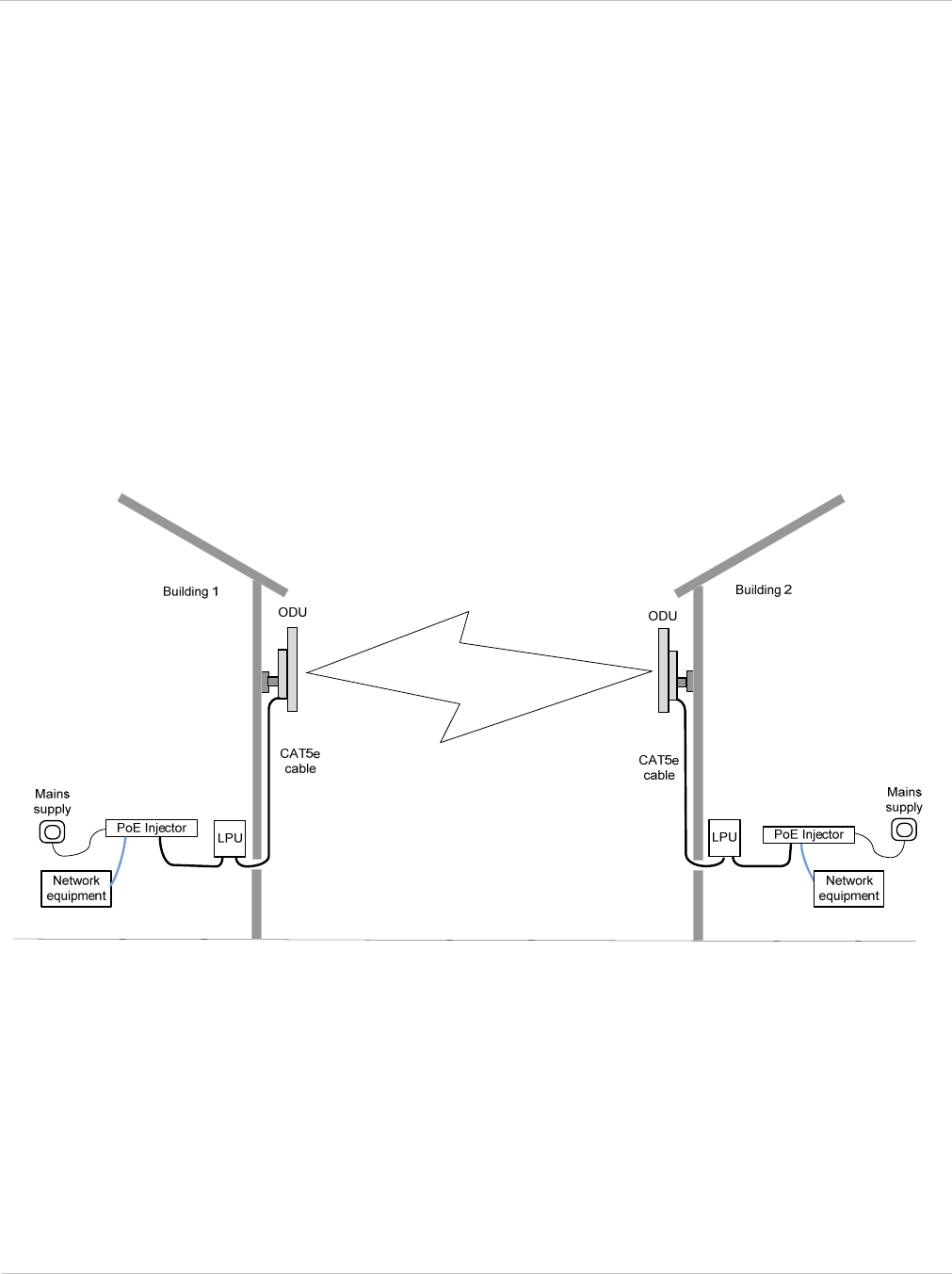
Typical deployment
The PTP 250 bridge consists of a pair of identical units, one deployed at each end of the
link. The radio link operates on a single frequency channel. One unit is configured as a
master and the other as a slave. The master unit takes responsibility for controlling the
link in both directions.
The bridge is aimed at a wide range of applications. One example is an enterprise that
needs to connect together the Local Area Network (LAN) of two or more buildings as
shown in Figure 1-1.
Figure 1-1 Typical PTP 250 bridge deployment (grounding not shown)
System components
Each end of the link consists of:
• Outdoor Unit (ODU): An integrated (or connectorized) outdoor transceiver unit
containing all the radio and networking electronics.
• PoE power supply: An indoor connection box containing a mains power supply, status
indicators and network connection port.
• Cabling and lightning protection: CAT5e cables, grounding cables, connectors and
a lightning protection unit (LPU).

Overview of the PTP 250 Chapter 1: Product description
1-4 UNDER DEVELOPMENT phn-2182_003v004 (Oct 2011)
Product variants
The PTP 250 is available in the following product variants:
• FCC/IC or ETSI/RoW: The PTP 250 is available in two regional variants: one is for use
in countries where FCC or IC licensing restrictions apply (FCC/IC), and the other is for
use in ETSI countries or the rest of the world (ETSI/RoW). The regional variants may
operate in the following bands:
o ETSI/RoW: 5.4 GHz or 5.8 GHz.
o FCC/IC: 5.4 GHz or 5.8 GHz only.
• Integrated or Connectorized: Both products are available in either Integrated (with
attached antenna) or Connectorized (without an antenna) variants.
• Link Complete or End Complete: The Link Complete kit consists of two ODUs and
two PoE power supply units. The End Complete kit consists of one ODU and one PoE
power supply unit.
To obtain part numbers for the above variants, refer to Ordering components on page 2-
24.
PTP 250 User Guide Outdoor unit (ODU)
phn-2182_003v004 (Oct 2011) UNDER DEVELOPMENT 1-5
Outdoor unit (ODU)
This section describes the PTP 250 ODU and its interfaces.
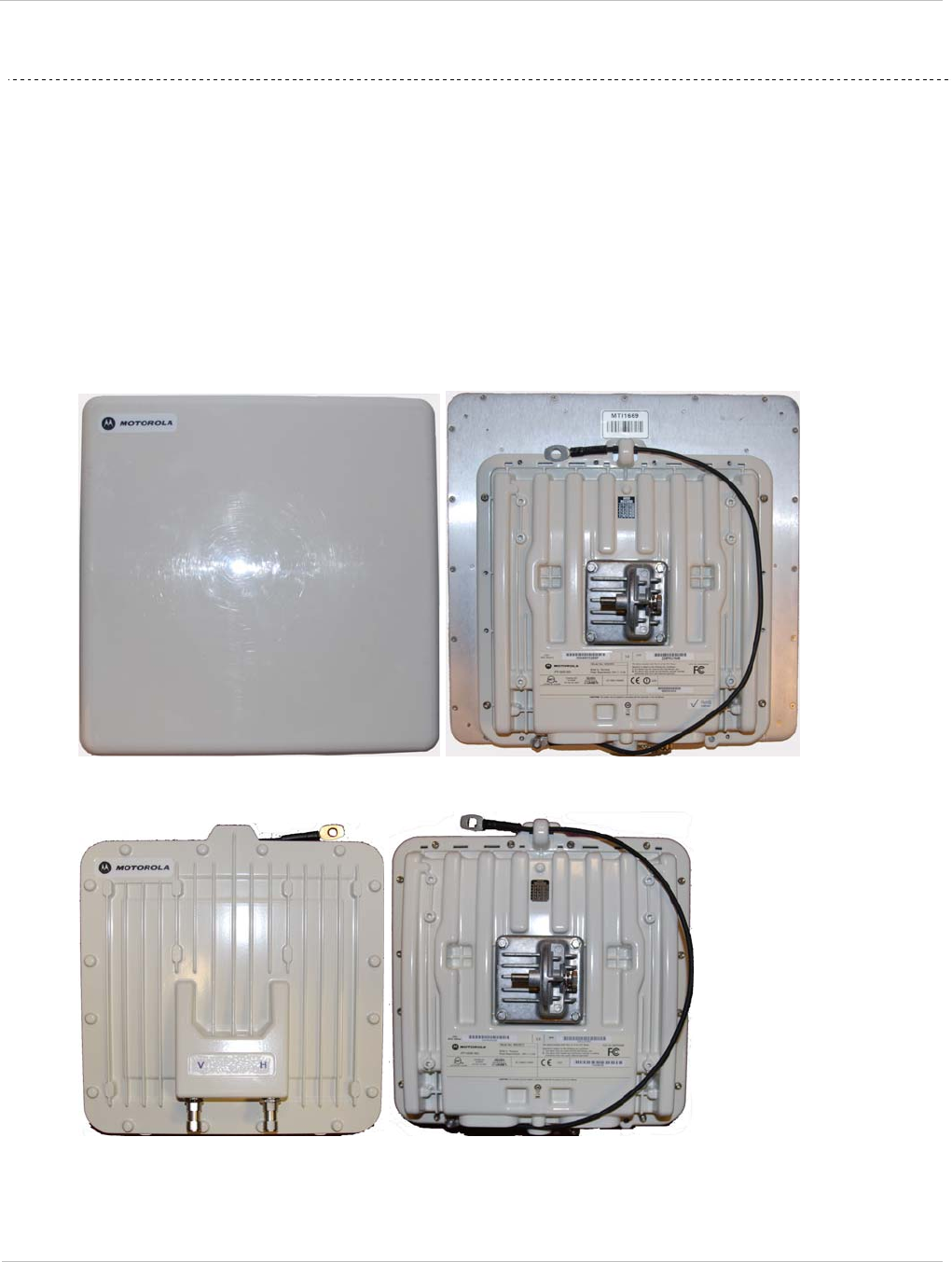
ODU description
The ODU is a self-contained unit that houses both radio and networking electronics. The
ODU is supplied in two configurations: integrated (attached to its own flat plate antenna,
Figure 1-2) or connectorized (without an antenna, Figure 1-3).
Figure 1-2 Integrated ODU (front and rear views)
Figure 1-3 Connectorized ODU (front and rear views)
Outdoor unit (ODU) Chapter 1: Product description
1-6 UNDER DEVELOPMENT phn-2182_003v004 (Oct 2011)
Connectorized variant
The connectorized ODU is designed to work with externally mounted antennas that have
higher gains than the integrated antenna. Connectorized units can cope with more difficult
radio conditions, as described in When to install connectorized units on page 2-12.
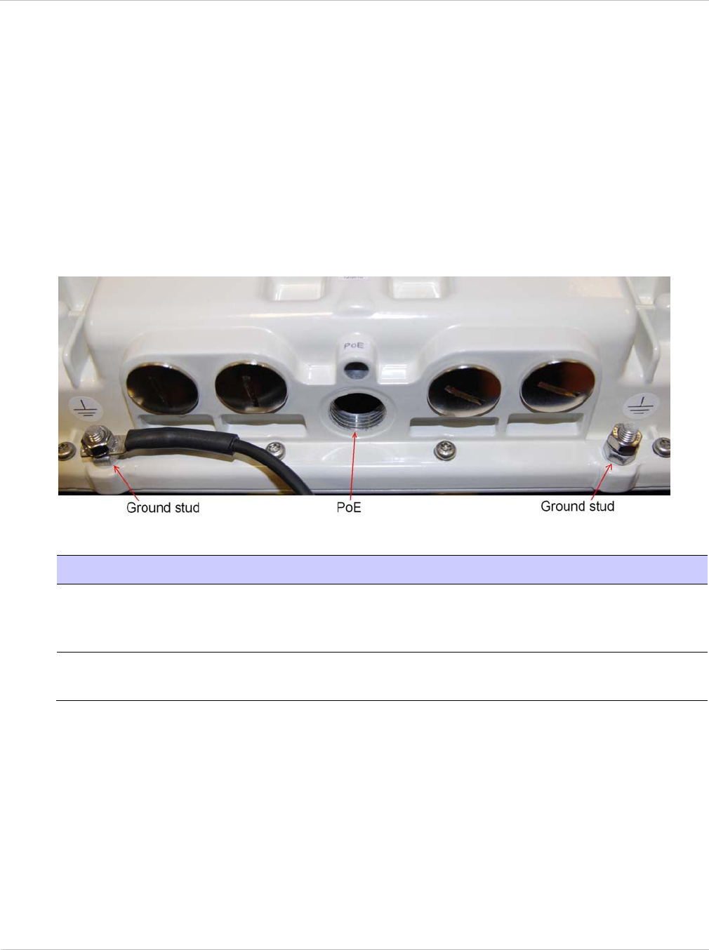
ODU interfaces
The ODU interfaces are illustrated in Figure 1-4 and described in Table 1-1.
Figure 1-4 ODU interfaces
Table 1-1 ODU interface functions
Interface Function
Ground studs For grounding the ODU to the supporting structure. The
ground cable (supplied with the ODU) may be connected to
either ground stud.
PoE RJ45 socket for connecting to power supply and network via
the PoE power supply.
PTP 250 User Guide Outdoor unit (ODU)
phn-2182_003v004 (Oct 2011) UNDER DEVELOPMENT 1-7
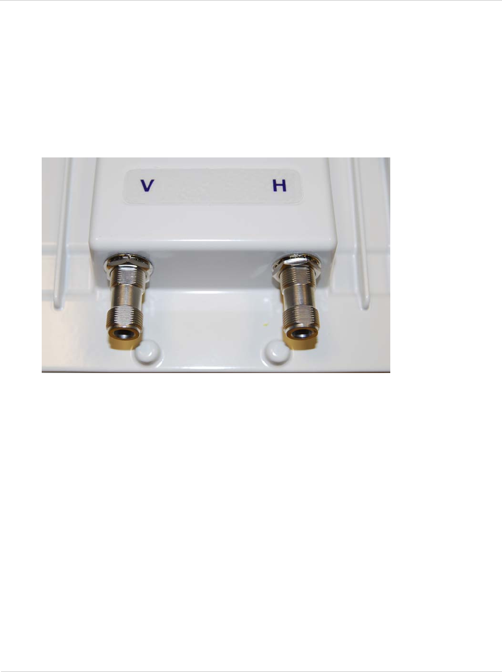
Connectorized ODU antenna interfaces
The connectorized ODU also has interfaces to connect to an external antenna (Figure 1-5)
via an N type connector with RF cable of type LMR100, LMR200, LMR300, LMR400 or
LMR600. The ‘V’ interface is for vertical polarization and the ‘H interface is for horizontal
polarization.
Figure 1-5 Connectorized ODU antenna interfaces
Mounting brackets
The ODU is supplied with a bracket for mounting it to a pole of 50mm (2”) to 75mm (3”) in
diameter.
The bracket allows for adjustment in both azimuth and elevation. The bracket may be split
to allow the pole mount section of the bracket to be mounted to the pole first. This allows
the installer to take the weight of the unit and secure it, one handed, with a single
mounting bolt.
Network connection
The network connection to the ODU is made via a 1000BaseT (Gigabit) Ethernet
connection. Power is provided to the ODU over the 1000BaseT Ethernet connection using
a standard IEEE 802.3at power supply.

Outdoor unit (ODU) Chapter 1: Product description
1-8 UNDER DEVELOPMENT phn-2182_003v004 (Oct 2011)
Further reading on the ODU
For more information on the ODU, refer to the following:
• ODU site selection on page 2-6 describes how to select a site for the ODU.
• When to install connectorized units on page 2-12 describes when to choose
connectorized ODUs and external antennas rather than integrated ODUs.
• General protection requirements on page 2-17 describes the grounding and lightning
protection requirements of a PTP 250 installation, including the ODU.
• Ordering components on page 2-24 lists the components required for PTP 250
installations, including ODUs, with Motorola part numbers.
• ODU specifications on page 4-2 contains specifications of the ODU such as dimensions,
weight and environmental requirements.
• FCC approved antennas on page 2-30 contains specifications of the antennas that may
be used with connectorized ODUs.
• Installing the ODU on page 5-4 describes how to install the ODU (integrated or
connectorized) on the supporting structure.
• Installing connectorized antennas on page 5-8 describes how to install separate
antenna(s) for a connectorized ODU.
• Aligning antennas on page 6-23 describes how to align the antennas for both
integrated and connectorized ODUs.

PTP 250 User Guide Power over Ethernet injector (PoE power supply)
phn-2182_003v004 (Oct 2011) UNDER DEVELOPMENT 1-9
Power over Ethernet injector (PoE power supply)
This section describes the PTP 250 Power over Ethernet injector (PoE power supply). One
or two PoE power supply units are provided with every PTP 250 kit.
The ODU should only be deployed with either the PoE power supply or the
PTP 300/500/600 Series PIDU. Do not use other power supply units, as they may damage
the PTP 250. For guidance on choosing the most suitable power supply unit, refer to Power
supply selection on page 2-6.
PoE power supply description
The Motorola High Power Gigabit PoE power supply (Motorola part number WB3727)
(Figure 1-6) is a single-port Power over Ethernet injector combining low-voltage DC with
Ethernet data in a single cable connecting to a PTP 250 ODU.
Figure 1-6 PoE power supply
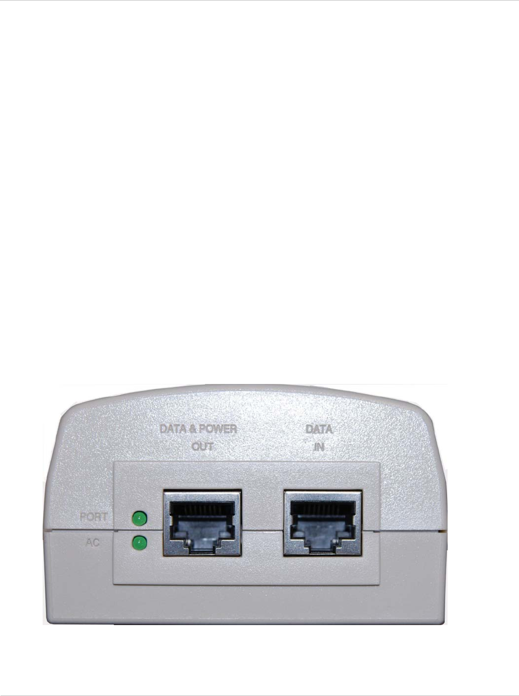
Power over Ethernet injector (PoE power supply) Chapter 1: Product description
1-10 UNDER DEVELOPMENT phn-2182_003v004 (Oct 2011)
PoE features
The PoE power supply has the following features:
• Independent power controller (SPEAR™), CPU controller and input (Data) and output
(Data & Power) shielded RJ-45 connectors.
• Supports standard 10/100/1000BaseT Ethernet networks over a standard TIA/EIA-568
Category 5 (or higher) cabling.
• Universal AC Input: 110/220 V, 60/50 Hz.
• Maximum available output power 30 W (nominal output voltage 52 to 56 V DC).
• Underload, overload, short-circuit and under/over voltage port protection.
• Port and AC power LED indicators.
• Standalone or wall mount installation support.
• Coupling rail and slot to allow two or more PoE power supply units to be mounted
together.
PoE power supply interfaces
The PoE power supply interfaces are illustrated in Figure 1-7 and described in Table 1-2
and Table 1-3.
Figure 1-7 PoE power supply interfaces

PTP 250 User Guide Power over Ethernet injector (PoE power supply)
phn-2182_003v004 (Oct 2011) UNDER DEVELOPMENT 1-11
Table 1-2 PoE power supply interface functions
Interface Function
IEC Power socket at rear Mains power input (100 – 240 V AC).
DATA & POWER OUT RJ45 socket for connecting CAT5e cable to ODU.
DATA IN RJ45 socket for connecting CAT5e cable to network.
Table 1-3 PoE power supply indicator LEDs
Indicator Function Description
AC Off The PoE power supply is not receiving power.
Green (steady) The PoE power supply is receiving power from an AC
outlet.
Green (blinking) The PoE power supply is receiving a voltage from the
AC outlet that is out of the correct range (100 – 240 V
AC).
Port Off There is no device connected to the DATA & POWER
OUT port.
Green (steady) A device is connected to the DATA & POWER OUT
port.
Green (blinking) The PoE power supply is overloaded or has a short
circuit.

Power over Ethernet injector (PoE power supply) Chapter 1: Product description
1-12 UNDER DEVELOPMENT phn-2182_003v004 (Oct 2011)
Further reading on the PoE power supply
For more information on the PoE power supply, refer to the following:
• Power supply selection on page 2-6 describes how to select a location for the PoE
power supply.
• Ordering components on page 2-24 lists the components required for PTP 250
installations, including PoE power supply units, with Motorola part numbers.
• Power supply unit specifications on page 4-3 contains specifications of the PoE power
supply (and the PIDU) such as dimensions, weight, environmental and electrical
requirements.
• Connecting to the unit on page 6-3 describes how to connect the PoE power supply to a
management PC to allow configuration and alignment of the PTP 250.
• Installing the PoE power supply on page 5-29 describes how to install the PoE power
supply, connect it to the ODU, and prepare the network cables.
• Connecting to the network on page 6-34 describes how to connect the PoE power
supply to the network when configuration, installation and alignment are complete.
• Testing link end hardware on page 8-2 describes how the PoE power supply is used
when testing the link end hardware for suspected faults.
PTP 250 User Guide Cabling and lightning protection
phn-2182_003v004 (Oct 2011) UNDER DEVELOPMENT 1-13
Cabling and lightning protection
This section describes the cabling and lightning protection components of PTP 250
installations.
PTP and lightning protection
The PoE power supply meets the low level static discharge specifications identified in
Electromagnetic compatibility (EMC) compliance on page 4-8 but does not provide
lightning or surge suppression.
The amount of lightning protection is dependent on regulatory and end user requirements.
The standard ODU is fitted with surge limiting circuits and other features to minimize the
risk of damage due to nearby lightning strikes. To be fully effective, these standard
features require some additional equipment to be configured as part of the system
installation.
The units are not designed to survive direct lightning strike. For this reason they
must not be installed in ‘Zone A’, as defined in Lightning protection zones on page
2-16. Mounting in Zone A may put equipment, structures and life at risk.
Outdoor connections
The term ‘drop cable’ refers to the cable that is used for all connections that terminate
outside the building, for example, connections between the ODU, LPU and PoE power
supply.
For outdoor connections, always use Cat5e cable that is gel-filled and shielded with
copper-plated steel. This is the only type of outdoor drop cable supported in this
application.

Cabling and lightning protection Chapter 1: Product description
1-14 UNDER DEVELOPMENT phn-2182_003v004 (Oct 2011)
Indoor connections
The CAT5e cable that connects the PoE power supply to the network equipment must meet
the following requirements:
• Screening: Must be either foil screen (FTP) or braided screen (STP) cable.
• Connectors: Must use screened RJ45 connectors with metal shells at both ends.
• Electrical connection: There must be a continuous electrical connection between
both screened connectors.
The connected network equipment must feature screened RJ45 connectors and must be
connected to ground, otherwise the PoE power supply will not be grounded, and this may
increase the levels of unwanted radiation from the ODU - PoE power supply cables.
Cable grounding kits
Drop cables must be grounded at the points specified in Grounding and lightning
protection on page 2-15. One cable grounding kit (Figure 1-8) is required for each drop
cable grounding point.
Figure 1-8 Cable grounding kit for 1/4” and 3/8” cable


Cabling and lightning protection Chapter 1: Product description
1-16 UNDER DEVELOPMENT phn-2182_003v004 (Oct 2011)
Further reading on cabling and lightning protection
For more information on cabling and lightning protection, refer to the following:
• Maximum cable lengths on page 2-7 gives maximum permitted lengths of interface
cables in PTP 250 installations.
• Grounding and lightning protection on page 2-15 describes the grounding and
lightning protection requirements of a PTP 250 installation.
• Ordering components on page 2-24 lists the components required for PTP 250
installations, including cables, connectors, grounding kits and LPUs.
• Installing the drop cable and LPU on page 5-15 describes how to install the drop cable
from the ODU to the LPU and PoE power supply, and to provide grounding for the
installation.
• Installing the PoE power supply on page 5-29 describes how to prepare the indoor
cables to connect to the network.
• Testing after a lightning strike on page 8-2 describes testing to be performed after a
PTP 250 installation is struck by lightning.

PTP 250 User Guide Wireless operation
phn-2182_003v004 (Oct 2011) UNDER DEVELOPMENT 1-17
Wireless operation
This section describes how PTP 250 wireless links are operated, including modulation
modes, power control and security.
Wireless Transmissions
The PTP 250 uses Time Division Duplexing (TDD) transmission, which means that a single
frequency channel is used for both Transmit and Receive. This is handled automatically by
the radio.
The PTP 250 transmits using Orthogonal Frequency Division Multiplexing (OFDM). This
wideband signal consists of many equally spaced sub-carriers. Although each sub-carrier is
modulated at a low rate using conventional modulation schemes, the resultant data rate
from all the sub-carriers is high.
The channel width of the OFDM signal is configurable to one of two values: 20 MHz or
40 MHz. The higher channel width provides greater link capacity at the expense of using
more spectrum. The lower channel width provides better receiver sensitivity and can also
be appropriate where the amount of free spectrum is limited.
Each channel is offset in center frequency from its neighboring channel by 20 MHz.
Spectrum management
At system start-up, the spectrum management feature of the PTP 250 monitors the
available wireless spectrum and directs both ends of the wireless link to operate on a
channel with a minimum level of co-channel and adjacent channel interference.
Alternatively, the user can specify a single channel to use (or several to be chosen from) at
the master unit.
Adaptive modulation
The PTP 250 can transport data over the wireless link using different modulation modes.
For a given channel width, each modulation mode transports data at a fixed rate. Also, the
receiver requires a given signal to noise ratio in order to successfully demodulate a given
modulation mode. Although the more complex modulations will transport data at a much
higher rate than the less complex modulation modes, the receiver requires a much higher
signal to noise ratio.
The system provides an adaptive modulation scheme where the receiver constantly
monitors the quality of the received signal and notifies the far end of the link of the
optimum modulation mode with which to transmit. In this way, optimum capacity is
achieved at all times.

Wireless operation Chapter 1: Product description
1-18 UNDER DEVELOPMENT phn-2182_003v004 (Oct 2011)
PTP LINKPlanner includes an estimate of mean data rate, the data rate provided by each
modulation and the percentage of time spent in each modulation mode.
MIMO
Multiple-Input Multiple-Output (MIMO) techniques provide protection against fading and
increase the probability that the receiver will decode a usable signal. When the effects of
MIMO are combined with those of OFDM techniques and a high link budget, there is a
high probability of a robust connection.
The PTP 250 transmits two signals on the same radio frequency, one of which is vertically
polarized and the other horizontally polarized. The system also has the ability to adapt
between two modes of operation:
• Dual Payload: When the radio channel conditions allow, the system will transmit two
different and parallel data streams, one on the vertical channel and one on the
horizontal channel. This doubles the capacity of the system.
• Single Payload: As the radio channel becomes more challenging, the system has the
ability to detect this and switch to a mode which transmits the same data stream on
both vertical and horizontal channels. This provides polar diversity and is another key
feature which allows the system to operate in challenging radio channels.
The switching between modes is automatically controlled by the adaptive modulation
feature described in Adaptive modulation on page 1-17.

PTP 250 User Guide Wireless operation
phn-2182_003v004 (Oct 2011) UNDER DEVELOPMENT 1-19
Radar avoidance
In regions where protection of radars is part of the local regulations, the PTP 250 must
detect interference from radar-like systems and avoid co-channel operation with these
systems.
To meet this requirement, the PTP 250 implements the following features:
ETSI regulations
The regulations have radar detection requirements for both master and slave devices.
The requirements for a master device are:
• The device can only transmit on available channels, of which there are none at initial
power up. The radar detection algorithm will always scan a usable channel
for 60
seconds (channel availability check) for radar interference before making the channel
an available channel.
• As a result of this compulsory channel scan, there is a service outage of at least 60
seconds every time radar is detected, and the installation time is extended by at least
60 seconds even if no radar is detected on the channel.
• When operating on a channel, the spectrum monitoring algorithm implements a radar
detection function (in-service monitoring) which looks for impulsive interference on the
operating channel. If impulsive interference is detected, spectrum management will
mark the current operating channel as having detected radar (unavailable channel) and
initiate a channel hop to an available channel. The previous operating channel will
remain in the unavailable state for 30 minutes after the impulsive interference pulse
was detected.
• After the 30 minutes have expired the channel will be returned to the usable channel
pool.
• There is a secondary requirement for bands requiring radar avoidance. Regulators
have mandated that products provide an approximately even loading of the spectrum
across all devices. In general, this prevents operation with fixed frequency allocations.
However, ETSI regulations do allow frequency planning of networks (as that has the
effect of spreading the load across the spectrum).
The Master device will not initiate any transmissions on channels which overlap the band
5600-5650 MHz as the radar detection requirements are more severe.

Wireless operation Chapter 1: Product description
1-20 UNDER DEVELOPMENT phn-2182_003v004 (Oct 2011)
The requirements for a slave device are:
• The slave device can only transmit after receiving a transmission from its associated
master to demonstrate that the channel is an available channel.
• The slave device is required to vacate the channel when the master device has detected
a radar signal.
• The slave device is also required to perform in-service monitoring
and will stop
transmitting on a channel having detected a radar signal (having informed the master
device) and will not re-use the channel for thirty minutes.
• Once the slave device has detected a radar on a channel, it will perform a channel
availability check
before transmitting again on the channel.
• The slave device is also required to perform Channel Availability Check (CAC)
measurements before responding to a master transmission, but this requirement only
applies after the slave has detected a radar signal on the channel.
Security
The PTP 250 supports 48-bit proprietary encryption for data transmitted over the wireless
link.
Country of operation
Some aspects of wireless operation are controlled, enforced or restricted according to
country of operation.
The Country Code must be set in the user interface by the user at first login. The Country
Code setting affects the following aspects of wireless operation:
• Maximum transmit power
• Radar avoidance
• Transmit power reduction in edge channels
• Frequency range
• Channel plan
To avoid possible enforcement action by the country regulator, always operate links in
accordance with local regulations.

PTP 250 User Guide Wireless operation
phn-2182_003v004 (Oct 2011) UNDER DEVELOPMENT 1-21
Equipment supplied to the USA can ONLY be set to operate with a Country Code which is
fully compatible with FCC Rules.
Using frequency planning
Networks will benefit from the use of fixed channel allocations if (a) the network consists
of multiple PTP links, and (b) RF interference predominantly arises from equipment in the
same network.
Frequency planning is the exercise of assigning operating channels to PTP units so as to
minimize RF interference between links. Frequency planning must consider interference
from any PTP unit to any other PTP unit in the network. Low levels of interference
normally allow for stable operation and high link capacity.
The frequency planning task is made more straightforward by use of the following
techniques:
• Using several different channels
• Separating units located on the same mast
• Using high performance (directional) external antennas
For help with planning networks, refer to Chapter 2: Planning considerations, or contact a
Motorola distributor or re-seller.

Wireless operation Chapter 1: Product description
1-22 UNDER DEVELOPMENT phn-2182_003v004 (Oct 2011)
Further reading on wireless operation
For information on planning wireless operation, refer to the following:
• Regulatory planning on page 2-2 describes the regulatory restrictions that affect radio
spectrum usage, such as frequency range and radar avoidance.
• Link planning on page 2-10 describes factors to be taken into account when planning
links, such as range and path loss, and introduces PTP LINKPlanner.
• Wireless specifications on page 4-5 contains specifications of the PTP 250 wireless
interface, such as RF bands, channel width, spectrum settings, maximum power and
link loss.
• Compliance with safety standards on page 4-8 lists the safety specifications against
which the PTP 250 has been tested, and describes how to keep RF exposure within
safe limits.
• Compliance with radio regulations on page 4-12 describes how the PTP 250 complies
with the radio regulations that are in force in various countries.
• Notifications on page 4-14 contains notifications of compliance with the radio
regulations that are in force in various regions.
For information on configuring and operating the wireless link, refer to the following:
• Using the installation wizard on page 6-13 describes how to configure the wireless
interface using the installation wizard.
• Comparing actual to predicted performance on page 6-33 describes how to check that
a newly installed link is achieving predicted levels of performance.
• Managing performance on page 7-17 describes how to manage the performance of a
PTP 250 link.
• Testing the radio link on page 8-12 describes what to do if the radio link is not working,
or it is unreliable, or the data throughput rate is too low.

PTP 250 User Guide Ethernet bridging
phn-2182_003v004 (Oct 2011) UNDER DEVELOPMENT 1-23
Ethernet bridging
This section describes how the PTP 250 controls Ethernet data in the customer and
management networks.
Customer network
Transparent Ethernet service
The PTP 250 provides an Ethernet service between the Ethernet port at a local ODU and
the Ethernet port at an associated remote ODU. The Ethernet service is based on
conventional layer two transparent bridging, and is equivalent to the Ethernet Private Line
(EPL) service defined by the Metro Ethernet Forum (MEF).
The service is transparent to untagged frames, standard VLAN frames, priority-tagged
frames, provider bridged frames, and provider backbone bridged frames. In each case, the
service preserves MAC addresses, VLAN ID, Ethernet priority and Ethernet payload in the
forwarded frame. The maximum frame size for bridged frames is 2000 octets.
Layer two control protocols
The PTP 250 is transparent to layer two control protocols (L2CP) including:
• Spanning tree protocol (STP), rapid spanning tree protocol (RSTP)
• Multiple spanning tree protocol (MSTP)
• Link aggregation control protocol (LACP)
• Link OAM, IEEE 802.3ah
• Port authentication, IEEE 802.1X
• Ethernet local management interface (E-LMI), ITU-T Q.933.
• Link layer discovery protocol (LLDP)
• Multiple registration protocol (MRP)
• Generic attribute registration protocol (GARP)
The system does not generate or respond to any L2CP traffic.

Ethernet bridging Chapter 1: Product description
1-24 UNDER DEVELOPMENT phn-2182_003v004 (Oct 2011)
Management network
IP interface
The PTP 250 ODU contains an embedded management agent with a single IP interface.
Network management communication is exclusively based on IP and associated higher
layer transport and application protocols. The factory default IP address of the
management agent is 169.254.1.1. The products do not require use of supplementary
serial interfaces.
MAC address
The MAC address is not configurable by the user.
VLAN membership
VLAN tagging is not supported for the management agent.
In-band management
In-band management is the only management mode offered (there is no out of band
management).
In the in-band management mode, the management agent can be reached from the
Ethernet port at the local ODU, and (assuming that the wireless link is established) the
Ethernet port at the remote ODU.
Wireless link down alert
PTP 250 offers a configurable email alert which can be set to send the user an email
message in the event of the wireless link going down.
Back-to-back links
PTP 250 will not operate correctly if a direct cabled connection is made between two PoE
power supply units. Where two or more links are deployed in a chain, always use an
Ethernet switch or router to interconnect the links at the relay points.
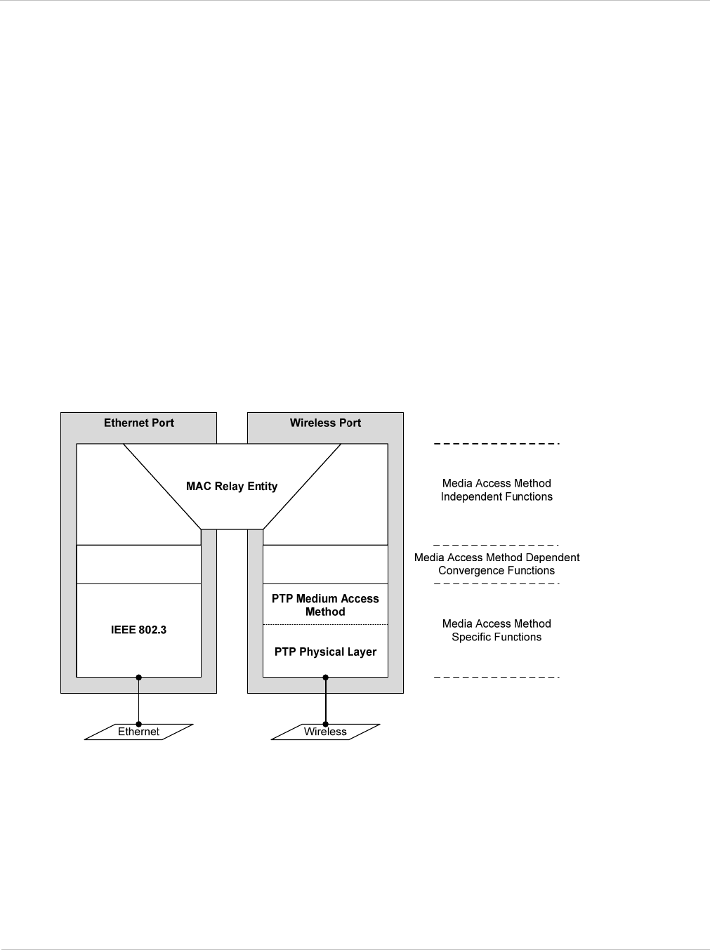
PTP 250 User Guide Ethernet bridging
phn-2182_003v004 (Oct 2011) UNDER DEVELOPMENT 1-25
Protocol model
Ethernet bridging behavior at each end of the wireless link is equivalent to a two-port,
managed, transparent MAC bridge where the two ports are:
• Ethernet Port
• Wireless Port
Frames are transmitted at the Wireless port over a proprietary point-to-point circuit-mode
link layer between ends of the link. Ethernet frames received at the Ethernet port, or
generated internally within the management agent, are encapsulated within a lightweight
MAC layer for transmission over the wireless link.
Protocol layers involved in bridging between Ethernet and wireless interfaces are shown in
Figure 1-10. Protocol layers involved in bridging between external interfaces and the
management agent are shown in Figure 1-11. In these figures, the layers have the
meanings defined in IEEE 802.1Q-2005.
Figure 1-10 Protocol layers between Ethernet and wireless interfaces
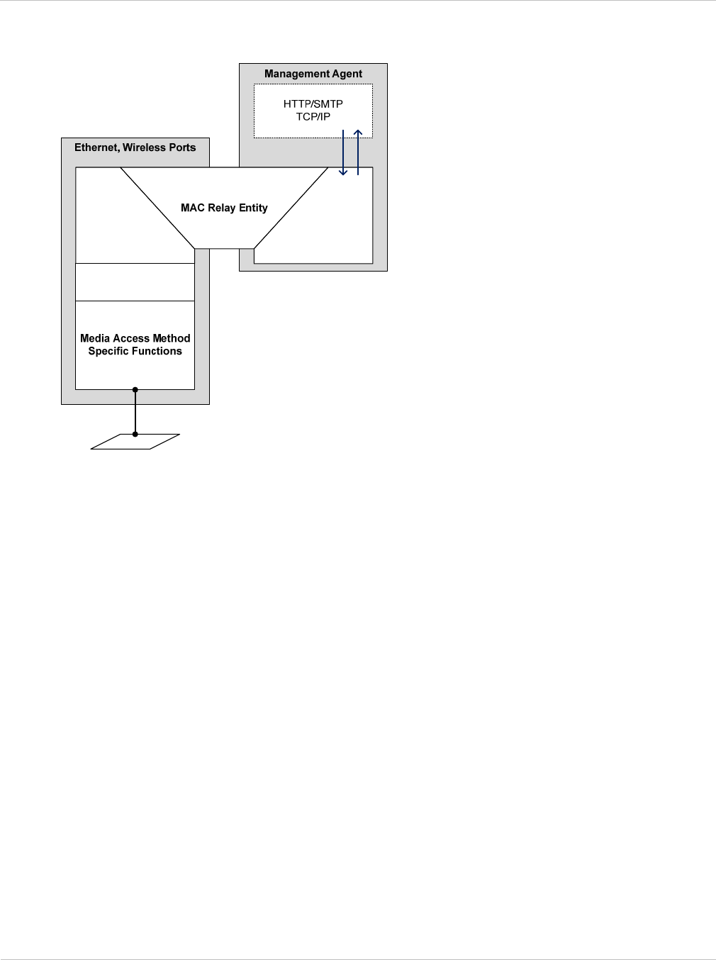
Ethernet bridging Chapter 1: Product description
1-26 UNDER DEVELOPMENT phn-2182_003v004 (Oct 2011)
Figure 1-11 Protocol layers between external interfaces and the management agent
Further reading on Ethernet bridging
For more information on Ethernet bridging, refer to the following:
• Data network planning on page 2-23 describes factors to be considered when planning
PTP 250 data networks.
• Data network specifications on page 4-7 contains specifications of the PTP 250
Ethernet interface.
• Using the installation wizard on page 6-13 describes how to configure the IP and
Ethernet attributes of the PTP 250.
• Reviewing system configuration attributes on page 6-30 describes how to review the IP
and Ethernet attributes of the PTP 250.

PTP 250 User Guide System management
phn-2182_003v004 (Oct 2011) UNDER DEVELOPMENT 1-27
System management
This section introduces the PTP 250 management system, including the web interface,
installation, configuration, alerts and upgrades.
Web server
The PTP 250 management agent contains a web server.
Web-based management offers a convenient way to manage the equipment from a locally
connected computer or from a workstation connected through a management network,
without requiring any special management software. The web-based interfaces are the
only interfaces supported for system installation and configuration management.
The web-based management interfaces provide comprehensive web-based fault,
configuration, performance and security management functions organized into the
following menu options:
• Home: This page reports wireless link status and basic information needed to identify
the link.
• Status: This page reports the detailed status of the system.
• Configuration: These pages are used to review the LAN, wireless, date and email
settings. These settings are updated using the Installation Wizard.
• Statistics: This page contains performance management counters that are collected at
the data, management and wireless ports.
• Firmware Update: This page is used to update the firmware in the unit.
• Diagnostics Plotter: This page provides diagnostic measurements over time, as an aid
to performance management.
• Installation Wizard: These pages are used to complete the initial system
configuration, including LAN, wireless, date and email settings.
• Change Password: The page is used to change the web-interface password.
• Reboot: This page is used to reboot the unit.
• Logout: This page is used to log out of the web-based interface.

System management Chapter 1: Product description
1-28 UNDER DEVELOPMENT phn-2182_003v004 (Oct 2011)
Firmware upgrade
The management agent supports application firmware upgrade using the web-based
interface.
PTP 250 firmware images are digitally signed, and the ODU will accept only images that
contain a valid Motorola PTP digital signature. The ODU always requires a reboot to
complete a firmware upgrade.
Obtain the application firmware and this user guide from the support website
(http://www.motorola.com/ptp/support) BEFORE warranty expires.
ODU firmware version must be the same at both ends of the link. Limited operation may
sometimes be possible with dissimilar firmware versions, but such operation is not
supported by Motorola.
The procedure for firmware upgrade is described in Upgrading firmware version on page
6-10.
Reset to factory defaults
The ‘reset to factory defaults’ feature provides a means to recover from serious
configuration errors, such as lost or forgotten passwords.
Use the reset plug (supplied in each PTP 250 ‘Link Complete’ or ‘End Complete’ kit) to
reset the unit to factory default configuration, including reset of the country that was
selected at first login. Following the procedure in Resetting to default configuration (with
country reset) on page 7-26
Use the Save & Restore page to reset the unit to factory default configuration, without
resetting the country that was selected at first login. Follow the procedure in Resetting to
default configuration (without country reset) on page 7-25.
Further reading on system management
For more information on system management, refer to the following:
• Chapter 6: Configuration and alignment describes all configuration and alignment
tasks that are performed when a PTP 250 link is deployed.
• Chapter 7: Operation provides instructions for operators of the PTP 250 web user
interface.

PTP 250 User Guide
phn-2182_003v004 (Oct 2011) UNDER DEVELOPMENT 2-1
Chapter 2: Planning considerations
This chapter provides information to help the user to plan a PTP 250 link.
The following topics are described in this chapter:
• Regulatory planning on page 2-2 describes how to plan PTP 250 links to conform to the
regulatory restrictions that apply in the country of operation.
• Site planning on page 2-6 describes factors to be considered when choosing sites for
the ODU and PoE power supply.
• Link planning on page 2-10 describes factors to be taken into account when planning
links, such as range and path loss. Introduces the PTP LINKPlanner.
• Planning for connectorized units on page 2-12 describes factors to be taken into
account when planning to use connectorized ODUs with external antennas in PTP 250
links.
• Grounding and lightning protection on page 2-15 describes the grounding and
lightning protection requirements of a PTP 250 installation.
• Data network planning on page 2-23 describes factors to be considered when planning
PTP 250 data networks.
• Ordering components on page 2-24 describes how to select components for a planned
PTP 250 link (as an alternative to PTP LINKPlanner). It specifies Motorola part
numbers for PTP 250 components.

Regulatory planning Chapter 2: Planning considerations
2-2 UNDER DEVELOPMENT phn-2182_003v004 (Oct 2011)
Regulatory planning
This section describes how to plan PTP 250 links to conform to the regulatory restrictions
that apply in the country of operation.
It is the responsibility of the user to ensure that the PTP product is operated in accordance
with local regulatory limits.
Contact the applicable radio regulator to find out whether or not registration of the
PTP 250 link is required.
Regulatory limits
The local regulator may restrict frequency usage and channel width, and may limit the
amount of conducted or radiated transmitter power. Table 2-1 contains examples of the
regulatory limits that apply in typical countries of operation.
Many countries impose EIRP limits (Allowed EIRP) on products operating in the 5.4 GHz
and 5.8 GHz bands. These limits are calculated as follows:
• In the 5.4 GHz band (5470 MHz to 5725 MHz), the EIRP must not exceed the lesser of
30 dBm or (17 + 10 x Log Channel width in MHz) dBm.
• In the 5.8 GHz band (5725 MHz to 5875 MHz), the EIRP must not exceed the lesser of
36 dBm or (23 + 10 x Log Channel width in MHz) dBm.
Some countries (for example the USA) impose conducted power limits on products
operating in the 5.8 GHz band.
Table 2-1 Example of regulatory limits
Country Band Permitted
frequencies Radar avoidance
(DFS) required? Power limit
USA 5.4 GHz 5470 - 5600 MHz
5650 - 5725 MHz
Yes (*) 30 dBm EIRP
USA 5.8 GHz 5725 - 5825 MHz No 30 dBm
conducted
UK 5.4 GHz 5470 - 5600 MHz
5650 - 5725 MHz
Yes 30 dBm EIRP
Denmark 5.8 GHz 5725 - 5795 MHz
5815 - 5875 MHz
Yes 36 dBm EIRP
(*) See also Avoidance of weather radars (USA only) on page 2-5.

PTP 250 User Guide Regulatory planning
phn-2182_003v004 (Oct 2011) UNDER DEVELOPMENT 2-3
Conforming to the limits
When a new PTP 250 unit is first accessed via the web interface, the user is required to
select the Country Code from a list. Generally, the PTP 250 firmware does not allow the
unit to be configured to operate outside the regulatory limits that apply to the selected
country. However, in the following situations, the firmware does not automatically prevent
operation outside the regulations:
• When using connectorized ODUs with external antennas, the regulations may require
the maximum transmit power to be reduced. To ensure that regulatory requirements
are met for connectorized installations, refer to Calculating maximum power level for
connectorized units on page 2-13.
• When installing 5.4 GHz links in the USA, it may be necessary to avoid frequencies
used by Terminal Doppler Weather Radar (TDWR) systems. For more information, refer
to Avoidance of weather radars (USA only) on page 2-5.
Available spectrum
The available spectrum for operation depends on the country of operation:
• The 5.4 GHz band is available in all EU countries.
• The 5.8 GHz band is currently only available in a limited number of EU countries (UK,
Eire, Norway, Denmark, Germany and Spain).
Certain regulations have allocated certain channels as unavailable for use:
• Europe has allocated part of the 5.4 GHz band to weather radar.
• The UK and some other European countries have allocated part of the 5.8 GHz band to
Road Transport and Traffic Telematics (RTTT) systems.
For examples of these restrictions, refer to Regulatory limits on page 2-2.
Where regulatory restrictions apply to certain channels, these channels are barred
automatically by the use of the correct country setting. For example, at 5.8 GHz in the UK
and some other European countries, the RTTT band 5795 MHz to 5815 MHz is barred.
With the appropriate configuration for a country in this region, the PTP 250 will not
operate on channels within this band.
The number and identity of channels barred by the country selection is dependent on the
channel width selected.

Regulatory planning Chapter 2: Planning considerations
2-4 UNDER DEVELOPMENT phn-2182_003v004 (Oct 2011)
Frequency selection
The PTP 250 fully conforms to regional regulatory requirements for radar avoidance.
In regions that mandate DFS, the unit first ensures that there is no radar activity on a
given channel for a period of 60 seconds before radiating on that channel. Once a channel
has been selected for operation, the unit will continually monitor for radar activity on the
operating channel. If detected, it will immediately cease radiating and attempt to find a
new channel.
Radar avoidance requirements in the 5.4 GHz band are defined as follows:
• For the EU: in specification EN 301-893 version V1.5.1.
Radar avoidance at 5.8 GHz is applicable to EU operation (not FCC/IC) and the
requirements are defined in EN 302 502.
Channel width
Select the required channel width for the link (20 MHz or 40 MHz). The wider channel has
the greater the capacity. As narrower channel widths take up less spectrum, selecting a
narrow channel width may be a better choice when operating in locations where the
spectrum is very busy.

PTP 250 User Guide Regulatory planning
phn-2182_003v004 (Oct 2011) UNDER DEVELOPMENT 2-5
Avoidance of weather radars (USA only)
To comply with FCC rules (
KDB 443999: Interim Plans to Approve UNII Devices Operating
in the 5470 - 5725 MHz Band with Radar Detection and DFS Capabilities
), units which are
installed within 35 km of a Terminal Doppler Weather Radar (TDWR) system (or have a
line of sight propagation path to such a system) must be configured to avoid any frequency
within +30 MHz or –30 MHz of the frequency of the TDWR device. This requirement
applies even if the master is outside the 35 km radius but communicates with outdoor
clients which may be within the 35 km radius of the TDWRs.
The requirement for ensuring 30 MHz frequency separation is based on the best
information available to date. If interference is not eliminated, a distance limitation based
on line-of-sight from TDWR will need to be used. In addition, devices with bandwidths
greater than 20 MHz may require greater frequency separation.
When planning a link in the USA, visit http://spectrumbridge.com/udrs/home.aspx, enter
the location of the planned link and search for TDWR radars. If a TDWR system is located
within 35 km (22 miles) or has line of sight propagation to the PTP device, perform the
following tasks:
• Register the installation on http://spectrumbridge.com/udrs/home.aspx.
• Use Table 2-2 to identify channel center frequencies that must be unselected, that is,
those falling within +30 MHz or –30 MHz of the frequency of the TDWR radars.
• Specify these channels in the installation report.
Table 2-2 Channels to be avoided when close to TDWR radars
PTP 250 channel
width TDWR frequency Channels to be unselected in
Step 2: Wireless Configuration
20 MHz <= 5610 MHz 5580 (116)
20 MHz >= 5630 MHz 5660 (132)
40 MHz >= 5630 MHz Channel pair 5660 & 5680 (132 & 136)
To comply with FCC rules, the affected channels must be unselected during staging,
before the units are allowed to radiate on site, as described in Step 2: Wireless
configuration on page 6-16.

Site planning Chapter 2: Planning considerations
2-6 UNDER DEVELOPMENT phn-2182_003v004 (Oct 2011)
Site planning
This section describes factors to be taken into account when choosing sites for the ODU
and PoE power supply.
ODU site selection
When selecting a site for the ODU, consider the following factors:
• Height and location to ensure that people are kept away from the antenna; see
Calculated distances and power compliance margins on page 4-10.
• Height and location to achieve the best radio path.
• Ability to meet the requirements specified in Grounding and lightning protection on
page 2-15.
• Aesthetics and planning permission issues.
• Cable lengths; see Maximum cable lengths on page 2-7.
• The effect of strong winds on the installation; see Wind loading on page 2-7.
Power supply selection
Select a suitable power supply unit for the PTP 250. The only supported units are the PoE
power supply (included in PTP 250 kits) or the PTP 300/500/600 Series PIDU. The PoE
power supply is suitable for the majority of installations, but the PIDU is required in the
following situations:
• When a -48 V DC power supply is required, either as the primary supply or as a backup
to the AC mains.
• When an extended operating temperature range is required for the mains powering
system, for example when the indoor equipment is in a building without temperature
control or air conditioning.
For PIDU ordering information, see Alternative components on page 2-34.
The power supply unit must be installed in an indoor location with no possibility of
condensation, with an ambient temperature within the specified operating range of the
product; see Power supply unit specifications on page 4-3.

PTP 250 User Guide Site planning
phn-2182_003v004 (Oct 2011) UNDER DEVELOPMENT 2-7
Maximum cable lengths
The maximum permitted lengths of interface cables in PTP 250 installations are specified
in Table 2-3.
Table 2-3 Maximum cable lengths
Interface type Interface Maximum
length
Ethernet power
and data
ODU to network terminating equipment. 100 m (330 ft)
Wind loading
Ensure that the supporting structure will not be prone to excessive wind loading.
Antennas and equipment mounted on towers or buildings will subject the mounting
structure to significant lateral forces when there is appreciable wind. Antennas are
normally specified by the amount of force (in pounds) for specific wind strengths. The
magnitude of the force depends on both the wind strength and size of the antenna.
The ODU, with or without the integral antenna, is essentially a flat structure. The
magnitude of the lateral force can be estimated from surface area and wind speed.
Calculation of lateral force (metric)
The magnitude of the lateral force can be estimated from:
Force (in kilograms) = 0.1045aV2
Where: Is:
a surface area in square meters
V wind speed in meters per second

Site planning Chapter 2: Planning considerations
2-8 UNDER DEVELOPMENT phn-2182_003v004 (Oct 2011)
The lateral force produced by a single PTP 250 ODU (integrated or connectorized model)
at different wind speeds is shown in Table 2-4.
Table 2-4 Lateral force – metric
Type of ODU Largest
surface area
(square meters)
Lateral force (Kg) at wind speed
(meters per second)
30 40 50 60 70
Integrated 0.130 12 22 34 49 66
Connectorized 0.093 9 16 24 35 48
Calculation of lateral force (US)
The magnitude of the lateral force can be estimated from:
Force (in pounds) = 0.0042Av2
Where: Is:
A surface area in square feet
v wind speed in miles per hour
The lateral force produced by a single PTP 250 ODU (integrated or connectorized model)
at different wind speeds is shown in Table 2-5.
Table 2-5 Lateral force – US
Type of ODU Largest
surface area
(square feet)
Lateral force (lb) at wind speed
(miles per hour)
80 100 120 140 150
Integrated 1.36 36.6 57.1 82.3 146.2 228.5
Connectorized 1.00 26.9 42 60.5 107.5 168.0
When the connectorized ODU is used with external antennas, the figures from the antenna
manufacturer for lateral force should be included to calculate the total loading on the
mounting structure.

PTP 250 User Guide Site planning
phn-2182_003v004 (Oct 2011) UNDER DEVELOPMENT 2-9
Capabilities of the PTP 250
The structure and mounting brackets of the ODU are capable of withstanding wind speeds
up to 242 kph (151 mph). Ensure that the structure to which the ODU is fixed is also
capable of withstanding the prevalent wind speeds and loads.
Wind speed statistics
Contact the national meteorological office for the country concerned to identify the likely
wind speeds prevalent at the proposed location. Use this data to estimate the total wind
loading on the support structures. Sources of information:
• US National Weather Service, http://www.nws.noaa.gov/
• UK Meteorological Office, www.meto.gov.uk

Link planning Chapter 2: Planning considerations
2-10 UNDER DEVELOPMENT phn-2182_003v004 (Oct 2011)
Link planning
This section describes factors to be taken into account when planning links, such as range,
obstacles and path loss. PTP LINKPlanner is recommended.
Range and obstacles
Calculate the range of the link and identify any obstacles that may affect radio
performance.
Perform a survey to identify all the obstructions (such as trees or buildings) in the path
and to assess the risk of interference. This information is necessary in order to achieve an
accurate link feasibility assessment.
When higher gain connectorized antennas are used, reduce the transmit power to ensure
that the receiver signal level does not exceed -20 dBm.
PTP LINKPlanner
The Motorola PTP LINKPlanner software and user guide may be downloaded from
http://www.motorola.com/ptp/support.
PTP LINKPlanner imports path profiles and predicts data rates and reliability over the
path. It allows the system designer to try different antenna heights and RF power settings.
It outputs an installation report that defines the parameters to be used for configuration,
alignment and operation. The installation report can be used to compare the predicted and
actual performance of the link.

PTP 250 User Guide Link planning
phn-2182_003v004 (Oct 2011) UNDER DEVELOPMENT 2-11
Path loss considerations
Path loss is the amount of attenuation the radio signal undergoes between the two ends of
the link.
Calculating path loss
The path loss is the sum of the attenuation of the path if there were no obstacles in the
way (Free Space Path Loss), the attenuation caused by obstacles (Excess Path Loss) and a
margin to allow for possible fading of the radio signal (Fade Margin). The calculation of
Equation 2-1 needs to be performed to judge whether a particular link can be installed.
Equation 2-1 Path loss
capabilityseasonalfadeexcessspacefree LLLLL
<
+++
_
Where is
spacefree
L_ Free Space Path Loss (dB)
excess
L Excess Path Loss (dB)
fade
L Fade Margin Required (dB)
seasonal
L Seasonal Fading (dB)
capability
L Equipment Capability (dB)
Adaptive modulation
Adaptive modulation ensures that the highest throughput that can be achieved
instantaneously will be obtained, taking account of propagation and interference. When
the link has been installed, web pages provide information about the link loss currently
measured by the equipment, both instantaneously and averaged. The averaged value will
require maximum seasonal fading to be added, and then the radio reliability of the link can
be computed.

Planning for connectorized units Chapter 2: Planning considerations
2-12 UNDER DEVELOPMENT phn-2182_003v004 (Oct 2011)
Planning for connectorized units
This section describes factors to be taken into account when planning to use connectorized
ODUs with external antennas in PTP 250 links.
When to install connectorized units
The majority of radio links can be successfully deployed with the integrated PTP 250.
However the integrated units may not be sufficient in some areas, for example:
• Where the path is heavily obscured by dense woodland on an NLOS link.
• Where long LOS links (>23 km or >14 miles) are required.
• Where there are known to be high levels of interference.
PTP LINKPlanner can be used to identify these areas of marginal performance.
In these areas, connectorized ODUs and external antennas should be used.
Choosing external antennas
When selecting external antennas, consider the following factors:
• The required antenna gain.
• Ease of mounting and alignment.
• Antenna polarization:
o For a simple installation process, select one dual-polarization antenna (as the
integrated antenna) at each end.
o To achieve spatial diversity, select two single-polarization antennas at each end.
Spatial diversity provides additional fade margin on very long LOS links where
there is evidence of correlation of the fading characteristics on Vertical and
Horizontal polarizations.
For connectorized units operating in the USA or Canada, choose external antennas from
those listed in FCC approved antennas on page 2-30. Do not install any other antennas.
For links in other countries, it is not mandatory to choose antennas from FCC approved
antennas on page 2-30, but this may be used as a guide.
If an EIRP limit is in force, refer to Calculating maximum power level for connectorized
units on page 2-13.

PTP 250 User Guide Planning for connectorized units
phn-2182_003v004 (Oct 2011) UNDER DEVELOPMENT 2-13
Calculating maximum power level for connectorized units
If a connectorized PTP 250 link is to be installed in a country that imposes an EIRP limit in
the 5.4 GHz or 5.8 GHz band, choose an external antenna and RF cable that will not cause
the PTP 250 to exceed the EIRP limit. To calculate the highest setting of Maximum Power
Level that will be permitted, use this formula:
Maximum Power Level (dBm) =
Allowed EIRP (dBm) – Antenna Gain (dBi) + Cable Loss (dB)
Where: Is:
Maximum Power
Level (dBm)
the highest permissible setting of the
Maximum Power Level attribute in the
Step 2: Wireless Configuration page,
Allowed EIRP
(dBm)
the EIRP limit allowed by the regulations,
Antenna Gain
(dBi)
the gain of the chosen antenna,
Cable Loss (dB)
the loss of the RF cable connecting the
ODU to the antenna.
As PTP 250 does not support Maximum Power Level settings below 4 dBm, the maximum
antenna gain (allowing for cable loss) is limited as shown in Table 2-6, based on this
formula:
Maximum Antenna Gain (dBi) – Cable Loss (dB) = Allowed EIRP (dBm) – 4
Table 2-6 Setting maximum power level to meet EIRP limits
Band Regulation Allowed
EIRP Maximum (Antenna
Gain - Cable Loss) Maximum Power
Level
5.4 GHz FCC,
Canada and
ETSI
30 dBm 26 dBi 4 dBm
5.8 GHz ETSI 36 dBm 32 dBi 4 dBm
Specify Antenna Gain and Cable Loss in the installation report. They must be entered
correctly in the Wireless Wizard, as they are used by the software to impose an automatic
constaint on Maximum Power Level. For more information, see Step 2: Wireless
configuration on page 6-16.

Planning for connectorized units Chapter 2: Planning considerations
2-14 UNDER DEVELOPMENT phn-2182_003v004 (Oct 2011)
Calculating RF cable length (5.8 GHz FCC only)
The 5.8 GHz band FCC approval for the product is based on tests with a cable loss
between the ODU and antenna of not less than 1.2 dB. If cable loss is below 1.2 dB with a
6 ft diameter external antenna, the connectorized PTP 250 may exceed the maximum
radiated spurious emissions allowed under FCC 5.8 GHz rules.
Cable loss depends mainly upon cable type and length. To meet or exceed the minimum
loss of 1.2 dB, use cables of the type and length specified in Table 2-7 (source: Times
Microwave). This data excludes connector losses.
Table 2-7 RF cable lengths required to achieve 1.2 dB loss at 5.8 GHz
RF cable type Minimum cable length
LMR100 0.6 m (1.9 ft)
LMR200 1.4 m (4.6 ft)
LMR300 2.2 m (7.3 ft)
LMR400 3.4 m (11.1 ft)
LMR600 5.0 m (16.5 ft)

PTP 250 User Guide Grounding and lightning protection
phn-2182_003v004 (Oct 2011) UNDER DEVELOPMENT 2-15
Grounding and lightning protection
This section describes the grounding and lightning protection requirements of a PTP 250
installation.
Electro-magnetic discharge (lightning) damage is not covered under warranty.
The recommendations in this guide, when followed correctly, give the user the
best protection from the harmful effects of EMD. However 100% protection is
neither implied nor possible.
The need for power surge protection
Structures, equipment and people must be protected against power surges (typically
caused by lightning) by conducting the surge current to ground via a separate preferential
solid path. The actual degree of protection required depends on local conditions and
applicable local regulations. Motorola recommends that PTP 250 installation is contracted
to a professional installer.
Standards
Full details of lightning protection methods and requirements can be found in the
international standards IEC 61024-1 and IEC 61312-1, the U.S. National Electric Code
ANSI/NFPA No. 70-1984 or section 54 of the Canadian Electric Code.
The requirements of Motorola manual
R56 Standards and Guidelines For Communication
Sites
take precedence over those in this guide.
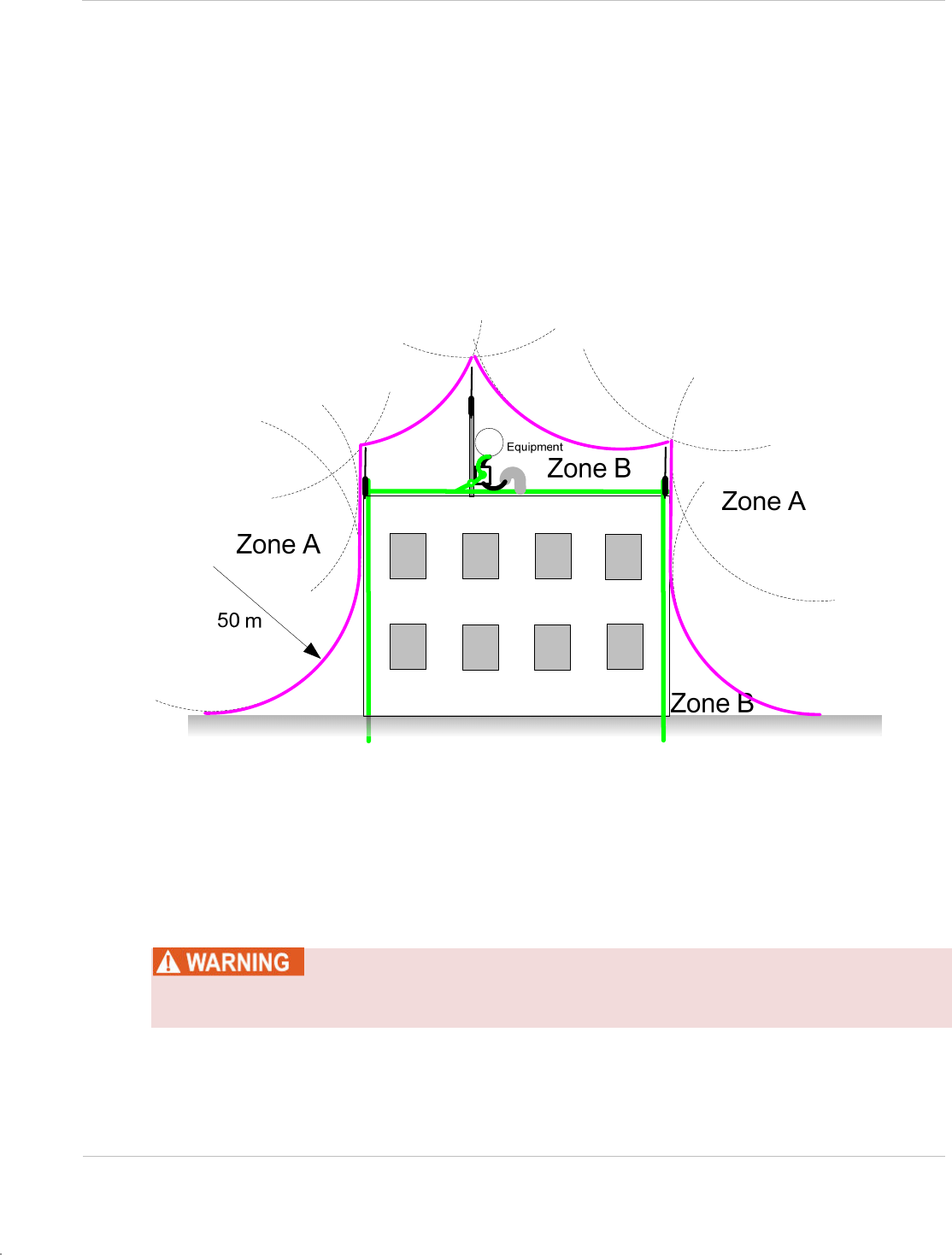
Grounding and lightning protection Chapter 2: Planning considerations
2-16 UNDER DEVELOPMENT phn-2182_003v004 (Oct 2011)
Lightning protection zones
The ‘rolling sphere method’ (Figure 2-1) is used to determine where it is safe to mount
equipment. An imaginary sphere, typically 50 meters in radius, is rolled over the
structure. Where the sphere rests against the ground and a strike termination device (such
as a finial or ground bar), all the space under the sphere is considered to be in the zone of
protection (Zone B). Similarly, where the sphere rests on two finials, the space under the
sphere is considered to be in the zone of protection.
Figure 2-1 Rolling sphere method to determine the lightning protection zones
Assess locations on masts, towers and buildings to determine if the location is in Zone A or
Zone B:
• Zone A: In this zone a direct lightning strike is possible. Do not mount equipment in
this zone.
• Zone B: In this zone, direct EMD (lightning) effects are still possible, but mounting in
this zone significantly reduces the possibility of a direct strike. Mount equipment in
this zone.
Never mount equipment in Zone A. Mounting in Zone A may put equipment,
structures and life at risk.

PTP 250 User Guide Grounding and lightning protection
phn-2182_003v004 (Oct 2011) UNDER DEVELOPMENT 2-17
General protection requirements
To adequately protect a PTP 250 installation, both ground bonding and transient voltage
surge suppression are required.
Basic requirements
The following basic protection requirements must be implemented:
• The ODU must be in ‘Zone B’ (see Lightning protection zones on page 2-16).
• A lightning protection unit (LPU) must be installed within 600 mm (24 in) of the point
at which the drop cable enters the building or equipment room.
• The drop cable must be bonded to the supporting structure in order to prevent
lightning creating a potential between the structure and cable, which could cause
arcing, resulting in fire risk and damage to equipment.
• The drop cable must be grounded at the building entry point.
• The drop cable must not be laid alongside a lightning air terminal.
• All grounding cables must be a minimum size of 10 mm2 csa (8AWG), preferably 16
mm2 csa (6AWG), or 25 mm2 csa (4AWG).
Grounding cable requirements
When routing, fastening and connecting grounding cables, the following requirements
must be implemented:
• Grounding conductors must be run as short, straight, and smoothly as possible, with
the fewest possible number of bends and curves.
• Grounding cables must not be installed with drip loops.
• All bends must have a minimum radius of 203 mm (8 in) and a minimum angle of 90°
(Figure 2-2). A diagonal run is preferable to a bend, even though it does not follow the
contour or run parallel to the supporting structure.
• All bends, curves and connections must be routed towards the grounding electrode
system, ground rod, or ground bar.
• Grounding conductors must be securely fastened.
• Braided grounding conductors must not be used.
• Approved bonding techniques must be used for the connection of dissimilar metals.

Grounding and lightning protection Chapter 2: Planning considerations
2-18 UNDER DEVELOPMENT phn-2182_003v004 (Oct 2011)
Figure 2-2 Grounding cable minimum bend radius and angle
Radius not less
than 203 mm (8 in)
Angle not less
than 90°
ODU requirements
The following ODU protection requirements must be implemented:
• The ODU must be grounded to the supporting structure.
Protection requirements for a mast or tower installation
If the ODU is to be mounted on a metal tower or mast, then in addition to the general
protection requirements (above), the following requirements must be observed:
• The equipment must be lower than the top of the tower or its lightning air terminal.
• The metal tower or mast must be correctly grounded.
• A grounding kit must be installed at the first point of contact between the drop cable
and the tower, near the top.
• A grounding kit must be installed at the bottom of the tower, near the vertical to
horizontal transition point. This grounding kit must be bonded to the tower or tower
ground bus bar (TGB), if installed.
• If the tower is greater than 61 m (200 ft) in height, an additional grounding kit must be
installed at the tower midpoint. Additional ground kits must be installed as necessary
to reduce the distance between ground kits to 61 m (200 ft) or less.
• In high lightning prone geographical areas, additional ground kits should be installed
at spacing between 15 to 22 m (50 to 75 ft). This is especially important on towers
taller than 45 m (150 ft).
A schematic example of a mast or tower installation is shown in Figure 2-3.
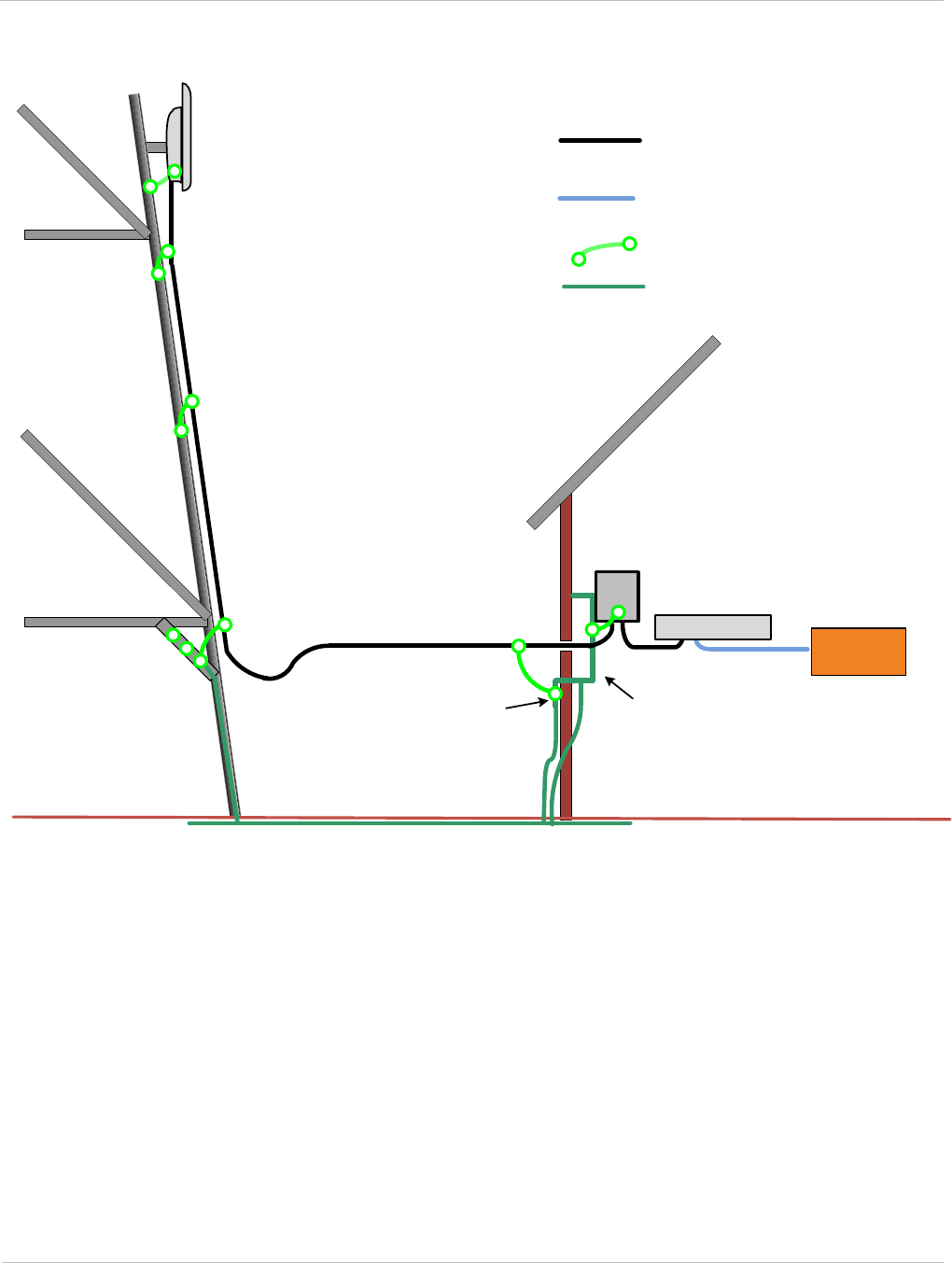
PTP 250 User Guide Grounding and lightning protection
phn-2182_003v004 (Oct 2011) UNDER DEVELOPMENT 2-19
Figure 2-3 Grounding and lightning protection on mast or tower
LPU
Tower
ground bar
External
ground bar
Master
ground bar
Ground ring
Outdoor CAT5e cable: gel-filled,
shielded with copper-plated steel
First point of contact with tower
Mid-point of tower
Bottom of tower
CAT5e cable: foil or braid screened,
with screened connectors
PoE Injector
Equipment building
Network
switch
ODU
PTP 250 ground cable
Tower/building ground system
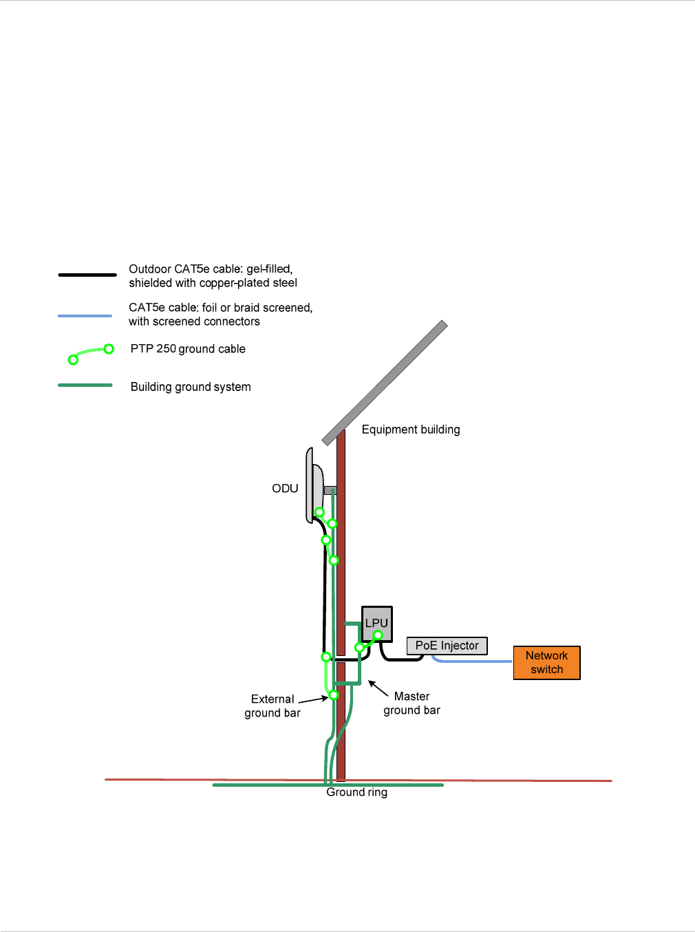
Grounding and lightning protection Chapter 2: Planning considerations
2-20 UNDER DEVELOPMENT phn-2182_003v004 (Oct 2011)
Protection requirements for a wall installation
If the ODU is to be mounted on the wall of a building, then in addition to the general
protection requirements (above), the following requirements must be observed:
• The equipment must be lower than the top of the building or its lightning air terminal.
• The building must be correctly grounded.
A schematic example of a wall installation is shown in Figure 2-4.
Figure 2-4 Grounding and lightning protection on wall
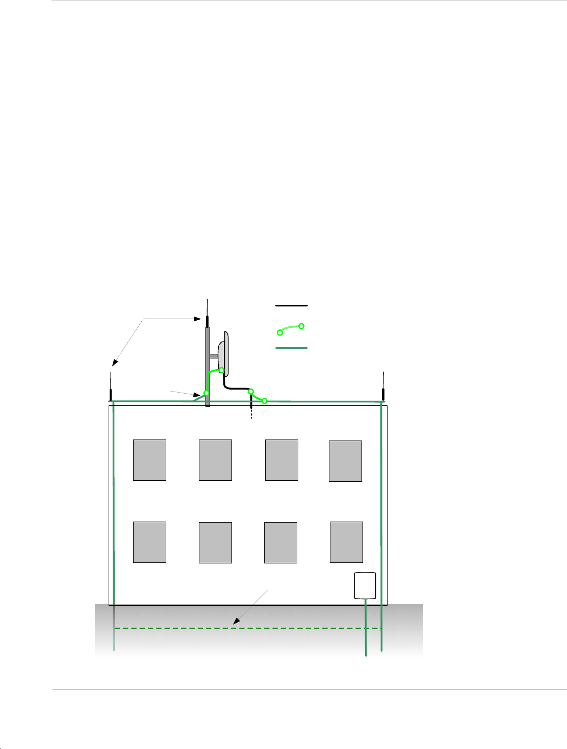
PTP 250 User Guide Grounding and lightning protection
phn-2182_003v004 (Oct 2011) UNDER DEVELOPMENT 2-21
Protection requirements on a high rise building
If the ODU is to be mounted on a high rise building, it is likely that cable entry is at roof
level (Figure 2-5) and the equipment room is several floors below (Figure 2-6). In addition
to the general protection requirements (above), the following requirements must be
observed:
• The ODU must be below the lightning terminals and finials.
• A grounding conductor must be installed around the roof perimeter, to form the main
roof perimeter lightning protection ring.
• Air terminals are typically installed along the length of the main roof perimeter
lightning protection ring typically every 6.1 m (20 ft).
• The main roof perimeter lightning protection ring must contain at least two down
conductors connected to the grounding electrode system. The down conductors should
be physically separated from one another, as far as practical.
Figure 2-5 Grounding and lightning protection on building
Air terminal (finial)
Tower grounding
conductor
Building ground ring AC
service
ODU
To equipment area
CAT5e cable: gel-filled, shielded
with copper-plated steel
PTP 250 ground cables
Building ground system
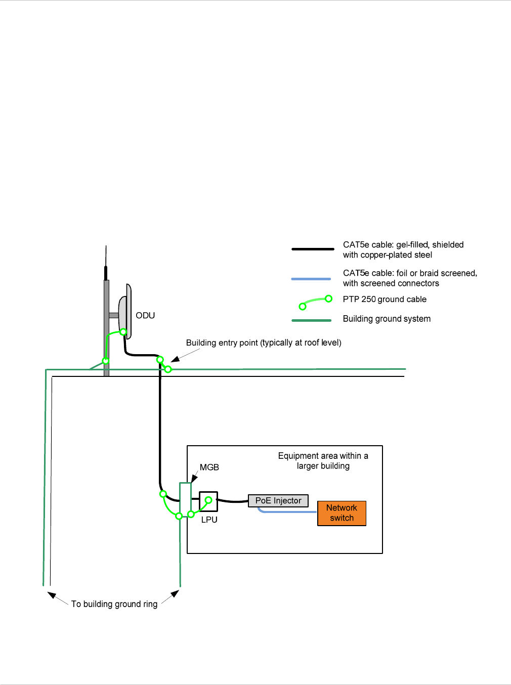
Grounding and lightning protection Chapter 2: Planning considerations
2-22 UNDER DEVELOPMENT phn-2182_003v004 (Oct 2011)
Protection inside a high rise building
The following protection requirements must be observed inside multi-story or high rise
buildings (Figure 2-6):
• The drop cable shield must be bonded to the building grounding system at the entry
point to the building.
• The drop cable shield must be bonded to the building grounding system at the entry
point to the equipment area.
• An LPU must be installed within 600 mm (24 in) of the entry point to the equipment
area.
Figure 2-6 Grounding and lightning protection inside high building

PTP 250 User Guide Data network planning
phn-2182_003v004 (Oct 2011) UNDER DEVELOPMENT 2-23
Data network planning
This section describes factors to be considered when planning PTP 250 data networks.
IP interface
Choose an IP address for the IP interface of the ODU management agent. The IP address
must be unique and valid for the connected network segment.
Ensure that the design of the data network permits bi-directional routing of IP datagrams
between network management systems and the ODUs. For example, ensure that the
gateway IP address identifies a router or other gateway that provides access to the rest of
the data network.
Back to back links
Do not use direct cabled connections between the data ports of two PoE power supplies.
Where two or more links are deployed in a chain, always use an Ethernet switch or router
to interconnect the links at a relay point.
‘Green Ethernet’ switches
Do not connect PTP 250 units to Ethernet networking products that control the level of the
transmitted Ethernet signal based on the measured length of the Ethernet link, for
example Green Ethernet products manufactured by D-Link Corporation. The Ethernet
interfaces in these networking products do not work correctly when connected directly to
the PoE power supply.

Ordering components Chapter 2: Planning considerations
2-24 UNDER DEVELOPMENT phn-2182_003v004 (Oct 2011)
Ordering components
This section describes describes how to select components for a planned PTP 250 link (as
an alternative to PTP LINKPlanner). It specifies Motorola part numbers for PTP 250
components.
PTP 250 kits
The PTP 250 is supplied as a 'Link' or an 'End' kit. A ‘Link’ kit contains components for
both ends of a link (including two ODUs and two PoE power supply units). An 'End' kit
contains components for one end of a link (including one ODU and one PoE power supply).
The kits may contain either integrated ODUs (antennas included) or connectorized ODUs
(separate antennas must be purchased).
PTP 250 kits are supplied in two regional variants: one is for use in countries where FCC
or IC licensing restrictions apply (the USA and Canada), and the other is for use in ETSI
countries or the rest of the world (ETSI/RoW). Table 2-8 contains part numbers for all kit
variants. Table 2-9 lists PTP 250 kit components.
Table 2-8 PTP 250 kit part numbers
Frequency
variant Regional
variant Integrated or
Connectorized Link or
End Complete
Part
number
5.4 / 5.8 GHz ETSI/RoW Integrated Link Complete WB3716
5.4 / 5.8 GHz ETSI/RoW Integrated End Complete WB3717
5.4 / 5.8 GHz ETSI/RoW Connectorized Link Complete WB3718
5.4 / 5.8 GHz ETSI/RoW Connectorized End Complete WB3719
5.4 / 5.8 GHz FCC/IC Integrated Link Complete WB3720
5.4 / 5.8 GHz FCC/IC Integrated End Complete WB3721
5.4 / 5.8 GHz FCC/IC Connectorized Link Complete WB3722
5.4 / 5.8 GHz FCC/IC Connectorized End Complete WB3723
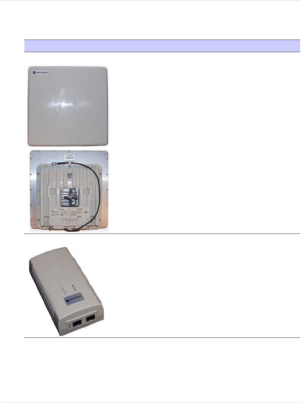
PTP 250 User Guide Ordering components
phn-2182_003v004 (Oct 2011) UNDER DEVELOPMENT 2-25
Table 2-9 Inventory for ODU and PoE power supply kits
Item Notes
ODUs
ODUs may be Integrated (as illustrated) or
Connectorized.
‘End Complete’ kit contains one ODU with
grounding cable.
‘Link Complete’ kit contains two ODUs with
grounding cables.
PoE power supply
‘End Complete’ kit contains one injector.
‘Link Complete’ kit contains two injectors.
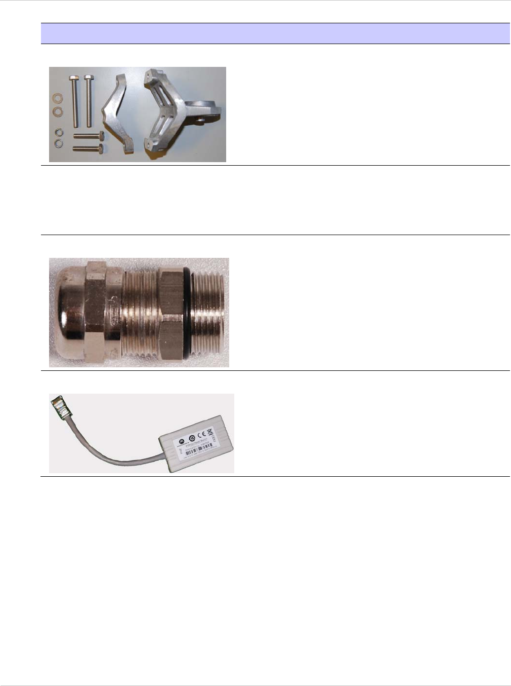
Ordering components Chapter 2: Planning considerations
2-26 UNDER DEVELOPMENT phn-2182_003v004 (Oct 2011)
Item Notes
Mounting bracket assembly
‘End Complete’ kit contains one bracket.
‘Link Complete’ kit contains two brackets.
Choice of mains leads (US, UK and
EU)
‘End Complete’ kit contains one US, one UK and
one EU lead.
‘Link Complete’ kit contains two US, two UK and
two EU leads.
Cable gland
‘End Complete’ kit contains one gland.
‘Link Complete’ kit contains two glands.
Reset plug
‘End Complete’ kit contains one switch.
‘Link Complete’ kit contains two switches.
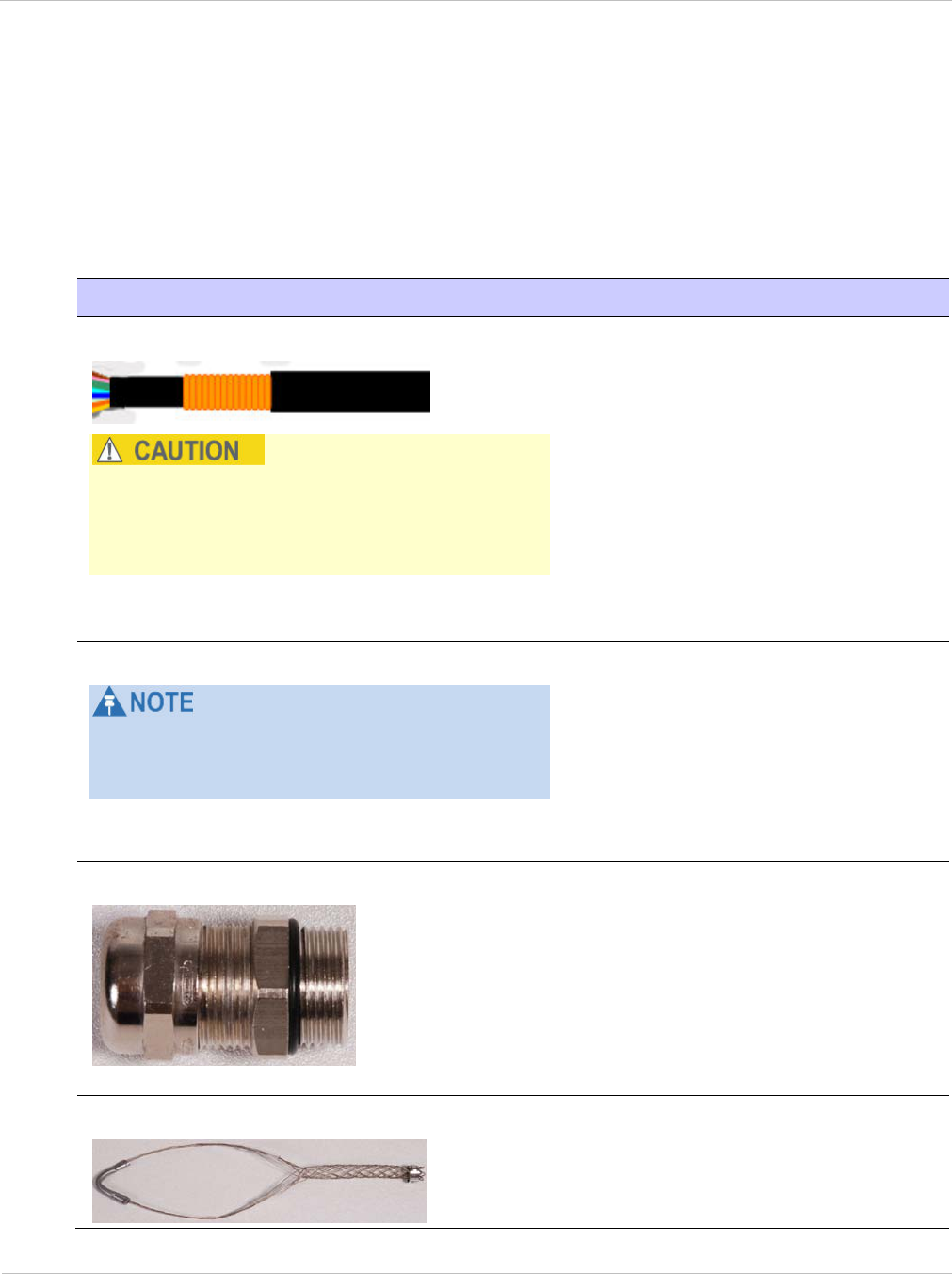
PTP 250 User Guide Ordering components
phn-2182_003v004 (Oct 2011) UNDER DEVELOPMENT 2-27
Other standard components
In addition to ODU and PoE power supply kits, standard installations require the
components listed in Table 2-10.
Table 2-10 Additional inventory for standard installations
Item Notes
Outdoor drop cable
Always use Cat5e cable that is gel-filled and
shielded with copper-plated steel. Alternative
types of drop cable are not supported by
Motorola.
Superior Essex BBDGe cable is
available from Motorola with the
following lengths and part numbers
(other lengths are available from
Superior Essex):
‘1000 ft Reel Outdoor Copper
Clad CAT5E’. Motorola part
number WB3175.
‘328 ft (100 m) Reel Outdoor
Copper Clad CAT5E’. Motorola
part number WB3176.
RJ45 connectors
The specified connectors, crimp tool and die
set are specific to Superior Essex BBDGe cable
(they may not work with other types of cable).
‘Tyco/AMP, Mod Plug RJ45
Unscreened, 25 pk’. Motorola part
number WB3177.
‘Tyco/AMP Crimp Tool’. Motorola
part number WB3211.
‘Tyco/AMP Die Set’. Available from
Tyco, part number 1-853400-0.
Cable glands
For protecting the drop cable entry
points. Glands are included in the
ODU and LPU kits, but additional
glands may be purchased from
Motorola if required.
‘PTP SER EMC CABLE GLAND
(GROUNDING)’. Quantity 10.
Motorola, part number WB1811.
Cable hoisting grip
For hoisting the drop cable up to the
ODU without damaging the gland or
RJ45 plug.
Not supplied by Motorola.
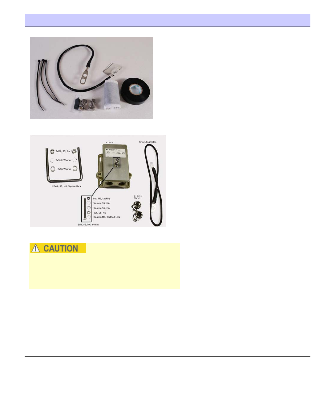
Ordering components Chapter 2: Planning considerations
2-28 UNDER DEVELOPMENT phn-2182_003v004 (Oct 2011)
Item Notes
Cable grounding kits
One kit is required per drop cable
grounding point.
‘Cable Grounding Kits For 1/4" And
3/8" Cable’. Motorola part number
01010419001.
Kit contents: grounding cable, self-
amalgamating tape, PVC tape, tie-
wraps, bolts, washers and nuts.
Lightning Protection Unit (LPU) kits
Two kits are required per standard
link.
‘LPU End Kit PTP 250/300/500’.
Motorola part number WB2978D.
Kit contents: one LPU, one grounding
cable, nuts, bolts and two cable
glands.
Indoor CAT5e cable
The connected network equipment must
feature screened RJ45 connectors and must be
connected to ground, otherwise the PoE power
supply will not be grounded.
To connect the PoE power supply to
network equipment, use screened
cable that meets this specification:
Screening: Must be either foil
screen (FTP) or braided screen
(STP) cable.
Connectors: Must use screened
RJ45 connectors with metal shells
at both ends.
Electrical connection: There
must be a continuous electrical
connection between both
screened connectors.

PTP 250 User Guide Ordering components
phn-2182_003v004 (Oct 2011) UNDER DEVELOPMENT 2-29
Item Notes
Drop cable tester
An optional item for testing the
resistances between the RJ45 pins of
the drop cable. Order from
http://www.motorola.com/ptp/support
by selecting Point-to-Point, Order
Cable Tester and completing the
order form.
Components required with connectorized ODUs
Connectorized ODUs require the additional components listed in Table 2-11.
Table 2-11 Additional inventory for connectorized ODUs
Item Notes
Antenna One required per link end (or two per link end
for spatial diversity). Not supplied by
Motorola.
For connectorized units operating in the USA
or Canada, choose external antennas from
those listed in FCC approved antennas on
page 2-30.
RF cable For connecting the ODU to the antenna. May
be cable of type LMR100, LMR200, LMR300,
LMR400 or LMR600. LMR400 is supplied by
Motorola:
‘50 Ohm Braided Coaxial Cable - 75
meter’. Motorola part number
30010194001.
‘50 Ohm Braided Coaxial Cable - 500
meter’. Motorola part number
30010195001.
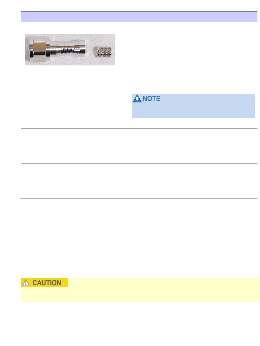
Ordering components Chapter 2: Planning considerations
2-30 UNDER DEVELOPMENT phn-2182_003v004 (Oct 2011)
Item Notes
N type male connectors
For connecting the RF cables to the ODU. Two
connectors required per ODU. Use
weatherproof connectors, preferably ones that
are supplied with adhesive lined heat shrink
sleeves that are fitted over the
cable/connector interface.
‘RF CONNECTOR,N,MALE,STRAIGHT FOR
CNT-400 CABLE’. Motorola part number
09010091001.
For the antenna end of the RF cable, refer to
the antenna manufacturer’s instructions.
Self-amalgamating and PVC tape To weatherproof the RF connectors.
Cable grounding kits One kit is required per antenna cable
grounding point.
Refer to Table 2-10 for specifications and part
numbers.
Lightning arrestor For protecting the antenna cable at building
entry, when the ODU is mounted indoors. One
required per antenna cable.
For example: Polyphaser LSXL-ME or LSXL.
FCC approved antennas
For connectorized units operating in the USA or Canada, choose external antennas from
Table 2-12 (5.4 GHz) or Table 2-13 (5.8 GHz). These are approved by the FCC for use with
the product and are constrained by the following limits for single- or dual-polarization
parabolic dish antennas:
• 5.4 GHz - up to 27 dBi per polarization or antenna.
• 5.8 GHz - up to 37.6 dBi per polarization or antenna.
Antennas not included in these tables are strictly prohibited for use with the PTP 250 in
the specified bands.

PTP 250 User Guide Ordering components
phn-2182_003v004 (Oct 2011) UNDER DEVELOPMENT 2-31
Table 2-12 Allowed antennas for deployment in USA/Canada – 5.4 GHz
Manufacturer Antenna Type Gain
(dBi)
RadioWaves Radio Waves 1.5-foot Parabolic, SP1.5-5.2 (25.3dBi) 25.3
RadioWaves 14 inch square flat plate FP-24-5 23.5
MARS 15 inch (370mm) square flat plate MA WS55.27 26.0
Table 2-13 Allowed antennas for deployment in USA/Canada – 5.8 GHz
Manufacturer Antenna Type Gain
(dBi) Parabolic
Dish
Andrew Andrew 2-foot Parabolic, P2F-52 (29.4
dBi)
29.4 Y
Andrew Andrew 2-foot Dual-Pol Parabolic, PX2F-
52 (29.4 dBi)
29.4 Y
Andrew Andrew 3-foot Parabolic, P3F-52 (33.4
dBi)
33.4 Y
Andrew Andrew 3-foot Dual-Pol Parabolic, PX3F-
52 (33.4 dBi)
33.4 Y
Andrew Andrew 4-foot Parabolic, P4F-52 (34.9
dBi)
34.9 Y
Andrew Andrew 4-foot Dual-Pol Parabolic, PX4F-
52 (34.9 dBi)
34.9 Y
Andrew Andrew 6-foot Parabolic, P6F-52 (37.6
dBi)
37.6 Y
Andrew Andrew 6-foot Dual-Pol Parabolic, PX6F-
52 (37.6 dBi)
37.6 Y
Gabriel Gabriel 2-foot High Performance
QuickFire Parabolic, HQF2-52-N
28.2 Y
Gabriel Gabriel 4-foot High Performance
QuickFire Parabolic, HQF4-52-N
34.4 Y
Gabriel Gabriel 6-foot High Performance
QuickFire Parabolic, HQF6-52-N
37.4 Y
Gabriel Gabriel 2-foot High Performance Dual
QuickFire Parabolic, HQFD2-52-N
28.1 Y
Gabriel Gabriel 4-foot High Performance Dual
QuickFire Parabolic, HQFD4-52-N
34.3 Y

Ordering components Chapter 2: Planning considerations
2-32 UNDER DEVELOPMENT phn-2182_003v004 (Oct 2011)
Manufacturer Antenna Type Gain
(dBi) Parabolic
Dish
Gabriel Gabriel 6-foot High Performance Dual
QuickFire Parabolic, HQFD6-52-N
37.3 Y
Gabriel Gabriel 2-foot Standard QuickFire
Parabolic,
QF2-52-N
28.5 Y
Gabriel Gabriel 2-foot Standard QuickFire
Parabolic,
QF2-52-N-RK
28.5 Y
Gabriel Gabriel 2.5-foot Standard QuickFire
Parabolic, QF2.5-52-N
31.2 Y
Gabriel Gabriel 4-foot Standard QuickFire
Parabolic,
QF4-52-N
34.8 Y
Gabriel Gabriel 4-foot Standard QuickFire
Parabolic,
QF4-52-N-RK
34.8 Y
Gabriel Gabriel 2-foot Standard Dual QuickFire
Parabolic, QFD2-52-N
28.4 Y
Gabriel Gabriel 2.5-foot Standard Dual QuickFire
Parabolic, QFD2.5-52-N
31.1 Y
Gabriel Gabriel 2-foot Standard Dual QuickFire
Parabolic, QFD2-52-N-RK
28.4 Y
Gabriel Gabriel 4-foot Standard Dual QuickFire
Parabolic, QFD4-52-N
34.7 Y
Gabriel Gabriel 4-foot Standard Dual QuickFire
Parabolic, QFD4-52-N-RK
34.7 Y
RadioWaves Radio Waves 2-foot Dual-Pol Parabolic,
SPD2-5.2 (28.1 dBi)
28.1 Y
RadioWaves Radio Waves 2-foot Parabolic, SP2-5.2
(29.0 dBi)
29 Y
RadioWaves Radio Waves 3-foot Dual-Pol Parabolic,
SPD3-5.2 (31.1 dBi)
31.1 Y
RadioWaves Radio Waves 3-foot Parabolic, SP3-5.2
(31.4 dBi)
31.4 Y
RadioWaves Radio Waves 4-foot Dual-Pol Parabolic,
SPD4-5.2 (34.4 dBi)
34.4 Y

PTP 250 User Guide Ordering components
phn-2182_003v004 (Oct 2011) UNDER DEVELOPMENT 2-33
Manufacturer Antenna Type Gain
(dBi) Parabolic
Dish
RadioWaves Radio Waves 4-foot Parabolic, SP4-5.2
(34.8 dBi)
34.8 Y
RadioWaves Radio Waves 6-foot Dual-Pol Parabolic,
SPD6-5.2 (37.5 dBi)
37.5 Y
RadioWaves Radio Waves 2-foot Parabolic, SP2-2/5
(28.3 dBi)
28.3 Y
RadioWaves Radio Waves 3-foot Parabolic, SP3-2/5
(31.4 dBi)
31.4 Y
RadioWaves Radio Waves 4-foot Parabolic, SP4-2/5
(34.6 dBi)
34.6 Y
RFS RFS 2-foot Parabolic, SPF2-52AN or
SPFX2-52AN (27.9 dBi)
27.9 Y
RFS RFS 3-foot Parabolic, SPF3-52AN or
SPFX3-52AN(31.4 dBi)
31.4 Y
RFS RFS 4-foot Parabolic, SPF4-52AN or
SPFX4-52AN(33.9 dBi)
33.9 Y
RFS RFS 6-foot Parabolic, SPF6-52AN or
SPFX6-52AN (37.4 dBi)
37.4 Y
RFS RFS 2-foot HP Parabolic, SDF2-52AN or
SDFX2-52AN (31.4 dBi)
31.4 Y
RFS RFS 4-foot HP Parabolic, SDF4-52AN or
SDFX4-52AN (33.9 dBi)
33.9 Y
RFS RFS 6-foot HP Parabolic, SDF6-52AN or
SDFX6-52AN (37.4 dBi)
37.4 Y
StellaDoradus StellaDoradus 45 inch Parabolic Antenna,
58PSD113
33.8 Y

Ordering components Chapter 2: Planning considerations
2-34 UNDER DEVELOPMENT phn-2182_003v004 (Oct 2011)
Alternative components
Some alternatives to standard PTP 250 components are listed in Table 2-14.
Table 2-14 Alternative PTP 250 components
Item Notes
Powered Indoor Unit (PIDU Plus)
This is the approved alternative to the PoE
power supply. It provides an interface to a -48
V DC power supply.
‘PTP 300/500/600 Series PIDU with AUS Lead’,
Motorola part number WB3022.
‘PTP 300/500/600 Series PIDU with EU Lead’,
Motorola part number WB3023.
‘PTP 300/500/600 Series PIDU with UK Lead’,
Motorola part number WB3024.
‘PTP 300/500/600 Series PIDU with US Lead’,
Motorola part number WB3025.
For guidance on choosing the most suitable
power supply unit, refer to Power supply
selection on page 2-6.

PTP 250 User Guide
phn-2182_003v004 (Oct 2011) UNDER DEVELOPMENT 3-1
Chapter 3: Legal information
This chapter provides legal notices including software license agreements.
Intentional or unintentional changes or modifications to the equipment must not be made
unless under the express consent of the party responsible for compliance. Any such
modifications could void the user’s authority to operate the equipment and will void the
manufacturer’s warranty.
The following topics are described in this chapter:
• Motorola Solutions, Inc. end user license agreement on page 3-2
• Hardware warranty on page 3-9
• Limit of liability on page 3-10

Motorola Solutions, Inc. end user license agreement Chapter 3: Legal information
3-2 UNDER DEVELOPMENT phn-2182_003v004 (Oct 2011)
Motorola Solutions, Inc. end user license agreement
In connection with Motorola’s delivery of certain proprietary software or products
containing embedded or pre-loaded proprietary software, or both, Motorola is willing to
license this certain proprietary software and the accompanying documentation to you only
on the condition that you accept all the terms in this End User License Agreement
(“Agreement”).
IF YOU DO NOT AGREE TO THE TERMS OF THIS AGREEMENT, DO NOT USE THE
PRODUCT OR INSTALL THE SOFTWARE. INSTEAD, YOU MAY, FOR A FULL REFUND,
RETURN THIS PRODUCT TO THE LOCATION WHERE YOU ACQUIRED IT OR PROVIDE
WRITTEN VERIFICATION OF DELETION OF ALL COPIES OF THE SOFTWARE. ANY USE
OF THE SOFTWARE, INCLUDING BUT NOT LIMITED TO USE ON THE PRODUCT, WILL
CONSTITUTE YOUR ACCEPTANCE TO THE TERMS OF THIS AGREEMENT.
Definitions
In this Agreement, the word “Software” refers to the set of instructions for computers, in
executable form and in any media, (which may include diskette, CD-ROM, downloadable
internet, hardware, or firmware) licensed to you. The word “Documentation” refers to
electronic or printed manuals and accompanying instructional aids licensed to you. The
word “Product” refers to Motorola’s MOTOwi4™ fixed wireless broadband devices for
which the Software and Documentation is licensed for use.
Grant of license
Motorola Solutions, Inc. (“Motorola”) grants you (“Licensee” or “you”) a personal,
nonexclusive, non-transferable license to use the Software and Documentation subject to
the Conditions of Use set forth in “Conditions of use” and the terms and conditions of
this Agreement. Any terms or conditions relating to the Software and Documentation
appearing on the face or reverse side of any purchase order, purchase order
acknowledgment or other order document that are different from, or in addition to, the
terms of this Agreement will not be binding on the parties, even if payment is accepted.

PTP 250 User Guide Motorola Solutions, Inc. end user license agreement
phn-2182_003v004 (Oct 2011) UNDER DEVELOPMENT 3-3
Conditions of use
Any use of the Software and Documentation outside of the conditions set forth in this
Agreement is strictly prohibited and will be deemed a breach of this Agreement.
1. Only you, your employees or agents may use the Software and Documentation. You
will take all necessary steps to insure that your employees and agents abide by the
terms of this Agreement.
2. You will use the Software and Documentation (i) only for your internal business
purposes; (ii) only as described in the Software and Documentation; and (iii) in strict
accordance with this Agreement.
3. You may use the Software and Documentation, provided that the use is in
conformance with the terms set forth in this Agreement.
4. Portions of the Software and Documentation are protected by United States
copyright laws, international treaty provisions, and other applicable laws. Therefore,
you must treat the Software like any other copyrighted material (for example, a book
or musical recording) except that you may either: (i) make 1 copy of the transportable
part of the Software (which typically is supplied on diskette, CD-ROM, or
downloadable internet), solely for back-up purposes; or (ii) copy the transportable part
of the Software to a PC hard disk, provided you keep the original solely for back-up
purposes. If the Documentation is in printed form, it may not be copied. If the
Documentation is in electronic form, you may print out 1 copy, which then may not be
copied. With regard to the copy made for backup or archival purposes, you agree to
reproduce any Motorola copyright notice, and other proprietary legends appearing
thereon. Such copyright notice(s) may appear in any of several forms, including
machine-readable form, and you agree to reproduce such notice in each form in which
it appears, to the extent it is physically possible to do so. Unauthorized duplication of
the Software or Documentation constitutes copyright infringement, and in the United
States is punishable in federal court by fine and imprisonment.
5. You will not transfer, directly or indirectly, any product, technical data or software
to any country for which the United States Government requires an export license or
other governmental approval without first obtaining such license or approval.

Motorola Solutions, Inc. end user license agreement Chapter 3: Legal information
3-4 UNDER DEVELOPMENT phn-2182_003v004 (Oct 2011)
Title and restrictions
If you transfer possession of any copy of the Software and Documentation to another party
outside of the terms of this agreement, your license is automatically terminated. Title and
copyrights to the Software and Documentation and any copies made by you remain with
Motorola and its licensors. You will not, and will not permit others to: (i) modify, translate,
decompile, bootleg, reverse engineer, disassemble, or extract the inner workings of the
Software or Documentation, (ii) copy the look-and-feel or functionality of the Software or
Documentation; (iii) remove any proprietary notices, marks, labels, or logos from the
Software or Documentation; (iv) rent or transfer all or some of the Software or
Documentation to any other party without Motorola’s prior written consent; or (v) utilize
any computer software or hardware which is designed to defeat any copy protection
device, should the Software and Documentation be equipped with such a protection
device. If the Software and Documentation is provided on multiple types of media (such as
diskette, CD-ROM, downloadable internet), then you will only use the medium which best
meets your specific needs, and will not loan, rent, lease, or transfer the other media
contained in the package without Motorola’s written consent. Unauthorized copying of the
Software or Documentation, or failure to comply with any of the provisions of this
Agreement, will result in automatic termination of this license.
Confidentiality
You acknowledge that all Software and Documentation contain valuable proprietary
information and trade secrets and that unauthorized or improper use of the Software and
Documentation will result in irreparable harm to Motorola for which monetary damages
would be inadequate and for which Motorola will be entitled to immediate injunctive relief.
If applicable, you will limit access to the Software and Documentation to those of your
employees and agents who need to use the Software and Documentation for your internal
business purposes, and you will take appropriate action with those employees and agents
to preserve the confidentiality of the Software and Documentation, using the same degree
of care to avoid unauthorized or improper disclosure as you use for the protection of your
own proprietary software, but in no event less than reasonable care.
You have no obligation to preserve the confidentiality of any proprietary information that:
(i) was in the public domain at the time of disclosure; (ii) entered the public domain
through no fault of yours; (iii) was given to you free of any obligation to keep it
confidential; (iv) is independently developed by you; or (v) is disclosed as required by law
provided that you notify Motorola prior to such disclosure and provide Motorola with a
reasonable opportunity to respond.

PTP 250 User Guide Motorola Solutions, Inc. end user license agreement
phn-2182_003v004 (Oct 2011) UNDER DEVELOPMENT 3-5
Right to use Motorola’s name
Except as required in “Conditions of use”, you will not, during the term of this Agreement
or thereafter, use any trademark of Motorola, or any word or symbol likely to be confused
with any Motorola trademark, either alone or in any combination with another word or
words.
Transfer
The Software and Documentation may not be transferred to another party without the
express written consent of Motorola, regardless of whether or not such transfer is
accomplished by physical or electronic means. Motorola’s consent may be withheld at its
discretion and may be conditioned upon transferee paying all applicable license fees and
agreeing to be bound by this Agreement.
Updates
During the first 12 months after purchase of a Product, or during the term of any executed
Maintenance and Support Agreement for the Product, you are entitled to receive Updates.
An “Update” means any code in any form which is a bug fix, patch, error correction, or
minor enhancement, but excludes any major feature added to the Software. Updates are
available for download at http://www.motorola.com/ptp/software.
Major features may be available from time to time for an additional license fee. If
Motorola makes available to you major features and no other end user license agreement
is provided, then the terms of this Agreement will apply.
Maintenance
Except as provided above, Motorola is not responsible for maintenance or field service of
the Software under this Agreement.

Motorola Solutions, Inc. end user license agreement Chapter 3: Legal information
3-6 UNDER DEVELOPMENT phn-2182_003v004 (Oct 2011)
Disclaimer
MOTOROLA DISCLAIMS ALL WARRANTIES OF ANY KIND, WHETHER EXPRESS,
IMPLIED, STATUTORY, OR IN ANY COMMUNICATION WITH YOU. MOTOROLA
SPECIFICALLY DISCLAIMS ANY WARRANTY INCLUDING THE IMPLIED WARRANTIES OF
MERCHANTABILTY, NONINFRINGEMENT, OR FITNESS FOR A PARTICULAR PURPOSE.
THE SOFTWARE AND DOCUMENTATION ARE PROVIDED “AS IS.” MOTOROLA DOES
NOT WARRANT THAT THE SOFTWARE WILL MEET YOUR REQUIREMENTS, OR THAT
THE OPERATION OF THE SOFTWARE WILL BE UNINTERRUPTED OR ERROR FREE, OR
THAT DEFECTS IN THE SOFTWARE WILL BE CORRECTED. MOTOROLA MAKES NO
WARRANTY WITH RESPECT TO THE CORRECTNESS, ACCURACY, OR RELIABILITY OF
THE SOFTWARE AND DOCUMENTATION. Some jurisdictions do not allow the exclusion
of implied warranties, so the above exclusion may not apply to you.
Limitation of liability
THE TOTAL LIABILITY OF MOTOROLA UNDER THIS AGREEMENT FOR DAMAGES WILL
NOT EXCEED THE TOTAL AMOUNT PAID BY YOU FOR THE PRODUCT LICENSED
UNDER THIS AGREEMENT. IN NO EVENT WILL MOTOROLA BE LIABLE IN ANY WAY
FOR INCIDENTAL, CONSEQUENTIAL, INDIRECT, SPECIAL OR PUNITIVE DAMAGES OF
ANY NATURE, INCLUDING WITHOUT LIMITATION, LOST BUSINESS PROFITS, OR
LIABILITY OR INJURY TO THIRD PERSONS, WHETHER FORESEEABLE OR NOT,
REGARDLESS OF WHETHER MOTOROLA HAS BEEN ADVISED OF THE POSSIBLITY OF
SUCH DAMAGES. Some jurisdictions do not permit limitations of liability for incidental or
consequential damages, so the above exclusions may not apply to you.
U.S. government
If you are acquiring the Product on behalf of any unit or agency of the U.S. Government,
the following applies. Use, duplication, or disclosure of the Software and Documentation
is subject to the restrictions set forth in subparagraphs (c) (1) and (2) of the Commercial
Computer Software – Restricted Rights clause at FAR 52.227-19 (JUNE 1987), if
applicable, unless being provided to the Department of Defense. If being provided to the
Department of Defense, use, duplication, or disclosure of the Products is subject to the
restricted rights set forth in subparagraph (c) (1) (ii) of the Rights in Technical Data and
Computer Software clause at DFARS 252.227-7013 (OCT 1988), if applicable. Software
and Documentation may or may not include a Restricted Rights notice, or other notice
referring specifically to the terms and conditions of this Agreement. The terms and
conditions of this Agreement will each continue to apply, but only to the extent that such
terms and conditions are not inconsistent with the rights provided to you under the
aforementioned provisions of the FAR and DFARS, as applicable to the particular
procuring agency and procurement transaction.

PTP 250 User Guide Motorola Solutions, Inc. end user license agreement
phn-2182_003v004 (Oct 2011) UNDER DEVELOPMENT 3-7
Term of license
Your right to use the Software will continue in perpetuity unless terminated as follows.
Your right to use the Software will terminate immediately without notice upon a breach of
this Agreement by you. Within 30 days after termination of this Agreement, you will
certify to Motorola in writing that through your best efforts, and to the best of your
knowledge, the original and all copies, in whole or in part, in any form, of the Software and
all related material and Documentation, have been destroyed, except that, with prior
written consent from Motorola, you may retain one copy for archival or backup purposes.
You may not sublicense, assign or transfer the license or the Product, except as expressly
provided in this Agreement. Any attempt to otherwise sublicense, assign or transfer any of
the rights, duties or obligations hereunder is null and void.
Governing law
This Agreement is governed by the laws of the United States of America to the extent that
they apply and otherwise by the laws of the State of Illinois.
Assignment
This agreement may not be assigned by you without Motorola’s prior written consent.
Survival of provisions
The parties agree that where the context of any provision indicates an intent that it
survives the term of this Agreement, then it will survive.
Entire agreement
This agreement contains the parties’ entire agreement regarding your use of the Software
and may be amended only in writing signed by both parties, except that Motorola may
modify this Agreement as necessary to comply with applicable laws.
Third party software
The software may contain one or more items of Third-Party Software supplied by other
third-party suppliers. The terms of this Agreement govern your use of any Third-Party
Software UNLESS A SEPARATE THIRD-PARTY SOFTWARE LICENSE IS INCLUDED, IN
WHICH CASE YOUR USE OF THE THIRD-PARTY SOFTWARE WILL THEN BE GOVERNED
BY THE SEPARATE THIRD-PARTY LICENSE.

Motorola Solutions, Inc. end user license agreement Chapter 3: Legal information
3-8 UNDER DEVELOPMENT phn-2182_003v004 (Oct 2011)
Trademarks
Java™ Technology and/or J2ME™ : Java and all other Java-based marks are trademarks or
registered trademarks of Sun Microsystems, Inc. in the U.S. and other countries.
Licenses and attributions
The document
PTP 250 Third Party Licenses and Attributions
(available for download at
www.motorola.com/ptp/software) contains licenses and attributions for third party
software components that are incorporated into the PTP 250 product.
To gain access to source code licensed under the GPL, please contact Motorola via the
support web site at www.Motorola.com/ptp/support/contact.

PTP 250 User Guide Hardware warranty
phn-2182_003v004 (Oct 2011) UNDER DEVELOPMENT 3-9
Hardware warranty
Motorola’s standard hardware warranty is for one (1) year from date of shipment from
Motorola or a Motorola Point-to-Point Distributor. Motorola warrants that hardware will
conform to the relevant published specifications and will be free from material defects in
material and workmanship under normal use and service. Motorola shall within this time,
at its own option, either repair or replace the defective product within thirty (30) days of
receipt of the defective product. Repaired or replaced product will be subject to the
original warranty period but not less than thirty (30) days.

Limit of liability Chapter 3: Legal information
3-10 UNDER DEVELOPMENT phn-2182_003v004 (Oct 2011)
Limit of liability
IN NO EVENT SHALL MOTOROLA BE LIABLE TO YOU OR ANY OTHER PARTY FOR ANY
DIRECT, INDIRECT, GENERAL, SPECIAL, INCIDENTAL, CONSEQUENTIAL, EXEMPLARY
OR OTHER DAMAGE ARISING OUT OF THE USE OR INABILITY TO USE THE PRODUCT
(INCLUDING, WITHOUT LIMITATION, DAMAGES FOR LOSS OF BUSINESS PROFITS,
BUSINESS INTERRUPTION, LOSS OF BUSINESS INFORMATION OR ANY OTHER
PECUNIARY LOSS, OR FROM ANY BREACH OF WARRANTY, EVEN IF MOTOROLA HAS
BEEN ADVISED OF THE POSSIBILITY OF SUCH DAMAGES. (Some states do not allow
the exclusion or limitation of incidental or consequential damages, so the above exclusion
or limitation may not apply to you.) IN NO CASE SHALL MOTOROLA’S LIABILITY
EXCEED THE AMOUNT YOU PAID FOR THE PRODUCT.

PTP 250 User Guide
phn-2182_003v004 (Oct 2011) UNDER DEVELOPMENT 4-1
Chapter 4: Reference information
This chapter describes the reference information and regulatory notices that apply to the
PTP 250.
The following reference topics are contained in this chapter:
• Equipment specifications on page 4-2 contains specifications of the ODU and power
supply unit that are required for PTP 250 installations.
• Wireless specifications on page 4-5 contains specifications of the PTP 250 wireless
interface, including RF bands, channel width and link loss.
• Data network specifications on page 4-7 contains specifications of the PTP 250
Ethernet interface.
• Compliance with safety standards on page 4-8 lists the safety specifications against
which the PTP 250 has been tested and certified. It also describes how to keep RF
exposure within safe limits.
• Compliance with radio regulations on page 4-12 describes how the PTP 250 complies
with the radio regulations that are in force in various countries.
• Notifications on page 4-14 contains notifications made to regulatory bodies for the
PTP 250.

Equipment specifications Chapter 4: Reference information
4-2 UNDER DEVELOPMENT phn-2182_003v004 (Oct 2011)
Equipment specifications
This section contains specifications of the ODU and power supply unit that are required for
PTP 250 installations.
ODU specifications
The ODU conforms to the specifications listed in Table 4-1, Table 4-2 and Table 4-3.
Table 4-1 Integrated ODU physical specifications
Category Specification
Dimensions Width 370 mm (14.5 in), Height 370 mm (14.5 in),
Depth 95 mm (3.75 in)
Weight 5.35 Kg (11.8 lbs) including bracket
Table 4-2 Connectorized ODU physical specifications
Category Specification
Dimensions Width 309 mm (12.2 in), Height 309 mm (12.2 in),
Depth 105 mm (4.01 in)
Weight 4.7 Kg (10.4 lbs) including bracket
Table 4-3 ODU environmental specifications
Category Specification
Temperature -40°C (40°F) to +60°C (140°F)
Wind loading 150 mph (242 kph) maximum. See Wind loading on page 2-7 for
a full description.
Humidity 100% condensing
Waterproofing IP66
UV exposure 10 year operational life (UL746C test evidence)

PTP 250 User Guide Equipment specifications
phn-2182_003v004 (Oct 2011) UNDER DEVELOPMENT 4-3
Power supply unit specifications
The power supply units conform to the specifications listed in Table 4-4, Table 4-5, Table
4-6 and Table 4-7.
Table 4-4 Power supply unit physical specifications
Category PoE power supply PIDU
Dimensions 88 mm x 51 mm x 166 mm
(3.5 ins x 2 ins x 6.5 ins)
250 mm x 40 mm x 80 mm
(9.75 ins x 1.5 ins x 3 ins)
Weight 0.35 Kg (0.77 lbs) 0.864 Kg (1.9 lbs)
Table 4-5 Power supply unit environmental specifications
Category PoE power supply PIDU
Operating temperature 0°C to 40°C
(32°F to 104°F)
-40°C to +60°C
(40°F to 140°F))
Storage temperature -20°C to 70°C
(-4°F to 158°F)
Operating humidity Maximum 90% Maximum 95%
non-condensing
Storage humidity Maximum 95%
Operating altitude -305 m to 3048 m
(-1000 ft to 10,000 ft)
Waterproofing Not waterproof Not waterproof
Table 4-6 Power supply unit electrical specifications
Category PoE power supply PIDU
AC input voltage 100 to 240 V AC 90 to 264 V AC
AC input current 0.8A @ 110 to 220 V AC
AC frequency 50 to 60 Hz 47 to 60 Hz
Alternative DC Input None. 37 to 60 V DC

Equipment specifications Chapter 4: Reference information
4-4 UNDER DEVELOPMENT phn-2182_003v004 (Oct 2011)
Table 4-7 PoE power supply Ethernet interface specifications
Category PoE power supply
Input (Data In) Ethernet 10/100/1000 Base-T
(RJ-45 female socket)
Output (Data & Power Out) Ethernet 10/100/1000 Base-T, plus 55 V DC (nominal)
RJ-45 female socket, with DC voltage on pairs 7-8 (-)
and 4-5 (+)
User Port Power: 30 Watts Max

PTP 250 User Guide Wireless specifications
phn-2182_003v004 (Oct 2011) UNDER DEVELOPMENT 4-5
Wireless specifications
This section contains specifications of the PTP 250 wireless interface. These specifications
include RF bands, channel width and link loss.
General wireless specifications
Table 4-8 contains radio system specifications for the 5.4 GHz band. Table 4-9 contains
radio system specifications for the 5.8 GHz band.
Table 4-8 5.4 GHz RF specifications
Radio technology Specification
RF band 5.470-5.725 GHz
Channel selection By dynamic frequency control and manual intervention
Automatic detection on start-up and continual adaptation.
Dynamic frequency control Initially 10-15 sec. Out of service on interference 100 ms.
Channel width 20 MHz and 40 MHz
Manual power control Maximum power can be controlled lower than the power
limits in order to control interference to other users.
Receiver noise figure Typically 6 dB
Integrated antenna type Integrated flat plate antenna; gain 23 dBi
External antenna gain See Calculating maximum power level for connectorized units
on page 2-13.
Antenna beamwidth 8 Degrees
Max path loss 150 dB (20 MHz channel, integrated antenna)
Range (optical line-of-sight) 54 km (34 miles) at channel width 20 MHz
27 km (17 miles) at channel width 40 MHz
Over-the-air encryption Proprietary scrambling mechanism.
Weather sensitivity Sensitivity at higher modes may be reduced during high winds
through trees due to Adaptive Modulation Threshold changes
Error correction FEC

Wireless specifications Chapter 4: Reference information
4-6 UNDER DEVELOPMENT phn-2182_003v004 (Oct 2011)
Table 4-9 5.8 GHz RF specifications
Radio technology Specification
RF band 5.725-5.850 GHz
Channel selection By dynamic frequency control and manual intervention
Automatic detection on start-up and continual adaptation.
Dynamic frequency control Initial capture 10-15 sec. Out of service on interference
100 ms.
Channel width 20 MHz and 40 MHz
Manual power control Maximum power can be controlled lower than the power
limits in order to control interference to other users.
Receiver noise figure Typically 6 dB
Antenna type (integrated) Flat plate antenna; gain 23 dBi
Antenna type (external) See FCC approved antennas on page 2-30.
Antenna beamwidth
(integrated)
8 degrees
Max path loss 150 dB (20 MHz channel, integrated antenna)
Range (optical line-of-sight) 54 km (34 miles) at channel width 20 MHz
27 km (17 miles) at channel width 40 MHz
Over-the-air encryption Proprietary scrambling mechanism.
Weather sensitivity Sensitivity at higher modes may be reduced during high
winds through trees due to Adaptive Modulation Threshold
changes
Error correction FEC

PTP 250 User Guide Data network specifications
phn-2182_003v004 (Oct 2011) UNDER DEVELOPMENT 4-7
Data network specifications
This section contains specifications of the PTP 250 Ethernet interface.
Ethernet interfaces
The PTP 250 Ethernet ports conform to the specifications listed in Table 4-10.
Table 4-10 Ethernet bridging specifications
Ethernet bridging Specification
Protocol IEEE802.1 compatible
Interface 1000BaseT (RJ-45), supports MDI/MDIX auto-
crossover
Maximum Ethernet data rate 220 Mbps
Maximum Ethernet frame size 2000 bytes
NOTE
Practical Ethernet rates will depend on network configuration, higher layer protocols and
platforms used.
Over the air throughput will be capped to the rate of the Ethernet interface at the
receiving end of the link.

Compliance with safety standards Chapter 4: Reference information
4-8 UNDER DEVELOPMENT phn-2182_003v004 (Oct 2011)
Compliance with safety standards
This section lists the safety specifications against which the PTP 250 has been tested and
certified. It also describes how to keep RF exposure within safe limits.
Electrical safety compliance
The PTP 250 hardware has been tested for compliance to the electrical safety
specifications listed in Table 4-11.
Table 4-11 Safety compliance specifications
Region Specification
USA UL60950-1, Second Edition
Canada CSA C22.2 No 60950-1, Second Edition
International CB Certified to IEC60950-1:2005 (Second Edition) and EN60950-
1:2006
Electromagnetic compatibility (EMC) compliance
The PTP 250 complies with European EMC Specification EN301 489-1 with testing carried
out to the detailed requirements of EN301 489-4.
For EN 61000-4-2: 1995 Electro Static Discharge (ESD), Class 2, 8 kV air, 4 kV contact
discharge, the PTP 250 have been tested to ensure immunity to 15 kV air and 8 kV contact.
Table 4-12 lists the EMC specification type approvals that have been granted for the
PTP 250.
Table 4-12 EMC emissions compliance
Region Specification (Type Approvals)
USA FCC Part 15 Class B
Canada RSS Gen and RSS 210
Europe EN55022 CISPR 22 and EN301 489-1/4

PTP 250 User Guide Compliance with safety standards
phn-2182_003v004 (Oct 2011) UNDER DEVELOPMENT 4-9
Human exposure to radio frequency energy
Relevant standards (USA and EC) applicable when working with RF equipment are:
•
ANSI IEEE C95.1-1991, IEEE Standard for Safety Levels with Respect to Human
Exposure to Radio Frequency Electromagnetic Fields, 3 kHz to 300 GHz.
• Council recommendation of 12 July 1999 on the limitation of exposure of the general
public to electromagnetic fields (0 Hz to 300 GHz) (1999/519/EC) and respective
national regulations.
•
Directive 2004/40/EC of the European Parliament and of the Council of 29 April 2004
on the minimum health and safety requirements regarding the exposure of workers to
the risks arising from physical agents (electromagnetic fields) (18th individual
Directive within the meaning of Article 16(1) of Directive 89/391/EEC).
• US FCC limits for the general population. See the FCC web site at http://www.fcc.gov,
and the policies, guidelines, and requirements in Part 1 of Title 47 of the Code of
Federal Regulations, as well as the guidelines and suggestions for evaluating
compliance in FCC OET Bulletin 65.
• Health Canada limits for the general population. See the Health Canada web site at
http://www.hc-sc.gc.ca/ewh-semt/pubs/radiation/99ehd-dhm237/limits-limites_e.html
and Safety Code 6.
• EN 50383:2002 Basic standard for the calculation and measurement of
electromagnetic field strength and SAR related to human exposure from radio base
stations and fixed terminal stations for wireless telecommunication systems (110 MHz -
40 GHz).
• BS EN 50385:2002 Product standard to demonstrate the compliances of radio base
stations and fixed terminal stations for wireless telecommunication systems with the
basic restrictions or the reference levels related to human exposure to radio frequency
electromagnetic fields (110 MHz – 40 GHz) – general public.
• ICNIRP (International Commission on Non-Ionizing Radiation Protection) guidelines for
the general public. See the ICNIRP web site at http://www.icnirp.de/ and Guidelines for
Limiting Exposure to Time-Varying Electric, Magnetic, and Electromagnetic Fields.
Power density exposure limit
Install the radios for the PTP 250 families of PTP wireless solutions so as to provide and
maintain the minimum separation distances from all persons.
The applicable power density exposure limit from the standards (see Human exposure to
radio frequency energy on page 4-9 ) is 10 W/m2 for RF energy in the 5.4 GHz and
5.8 GHz frequency bands.
Calculation of power density
NOTE

Compliance with safety standards Chapter 4: Reference information
4-10 UNDER DEVELOPMENT phn-2182_003v004 (Oct 2011)
The following calculation is based on the ANSI IEEE C95.1-1991 method, as that provides
a worst case analysis. Details of the assessment to EN50383:2002 can be provided, if
required.
Peak power density in the far field of a radio frequency point source is calculated as
follows:
Where: Is:
S
power density in W/m2
P
maximum average transmit power
capability of the radio, in W
G
total Tx gain as a factor, converted
from dB
d
distance from point source, in m.
Rearranging terms to solve for distance yields:
Calculated distances and power compliance margins
Table 4-13 shows calculated minimum separation distances, recommended distances and
resulting margins for each frequency band and antenna combination. These are
conservative distances that include compliance margins. At these and greater separation
distances, the power density from the RF field is below generally accepted limits for the
general population.
Explanation of terms used in Table 4-13:
Tx burst – maximum average transmit power in burst (Watt)
P – maximum average transmit power capability of the radio (Watt)
G – total transmit gain as a factor, converted from dB
S – power density (W/m2)
d – minimum distance from point source (meters)
R – recommended distances (meters)
2
4
.
d
GP
S
π
=
S
GP
d.4
.
π
=

PTP 250 User Guide Compliance with safety standards
phn-2182_003v004 (Oct 2011) UNDER DEVELOPMENT 4-11
Table 4-13 Power compliance margins
Band Antenna Tx Burst
(W) P (W) G S
(W/m2) d (m) R (m)
5.4 GHz
Integrated 0.0050 0.0050 200
10 0.089 1
Max gain
connectorized
0.0025 0.0025 398
10 0.089 1
ETSI
5.8 GHz
Integrated 0.0200 0.0200 200
10 0.178 1
Max gain
connectorized
0.0025 0.0025 1585
10 0.178 1
FCC
5.8 GHz
Integrated
(*1)
0.34 0.34 141
10 0.62 2
Max gain
connectorized
(*1)
0.34 0.34 3630
10 3.13 5
(*1) The figures for these antennas include cable losses.
Gain of antenna in dBi = 10*log(G).
The regulations require that the power used for the calculations is the maximum power in
the transmit burst subject to allowance for source-based time-averaging.
At 5.4 GHz and EU 5.8 GHz, the products are generally limited to a fixed EIRP which can
be achieved with the Integrated Antenna. The calculations above assume that the
maximum EIRP allowed by the regulations is being transmitted.
If there are no EIRP limits in the country of deployment, use the distance calculations for
FCC 5.8 GHz for all frequency bands.
At FCC 5.8 GHz, for antennas between 0.6m (2ft) and 1.8m (6ft), alter the distance
proportionally to the antenna gain.

Compliance with radio regulations Chapter 4: Reference information
4-12 UNDER DEVELOPMENT phn-2182_003v004 (Oct 2011)
Compliance with radio regulations
This section describes how the PTP 250 complies with the radio regulations that are in
force in various countries.
Changes or modifications not expressly approved by Motorola could void the user’s
authority to operate the system.
Type approvals
This system has achieved Type Approval in various countries around the world. This means
that the system has been tested against various local technical regulations and found to
comply. The frequency bands in which the system operates may be ‘unlicensed’ and, in
these bands, the system can be used provided it does not cause interference. Further, it is
not guaranteed protection against interference from other products and installations.
Table 4-14 lists the radio specification type approvals that have been granted for PTP 250.
Table 4-14 Radio certifications
Band Region Specification (Type Approvals)
5.4 GHz USA FCC Part 15 E
Canada RSS 210 Issue 7, Annex 9
Europe EN301 893 V1.5.1
5.8 GHz USA FCC Part 15.247
Canada RSS 210 Issue 7, Annex 8
UK IR 2007
Eire ComReg 06/47R
Germany Order No 47/2007
EU EN302 502 v 1.2.1
Spain CNAF-2010-BOE
Norway REG 2009-06-02 no. 580
Denmark Danish radio interface 00 007

PTP 250 User Guide Compliance with radio regulations
phn-2182_003v004 (Oct 2011) UNDER DEVELOPMENT 4-13
FCC and ETSI compliance testing
The system has been tested for compliance to both US (FCC) and European (ETSI)
specifications. It has been shown to comply with the limits for emitted spurious radiation
for a Class B digital device, pursuant to Part 15 of the FCC Rules in the USA and
appropriate European ENs. These limits have been designed to provide reasonable
protection against harmful interference. However the equipment can radiate radio
frequency energy and, if not installed and used in accordance with the instructions, may
cause harmful interference to other radio communications. There is no guarantee that
interference will not occur in a particular installation.
A Class B Digital Device is a device that is marketed for use in a residential environment,
notwithstanding use in commercial, business and industrial environments.
Notwithstanding that Motorola has designed (and qualified) the PTP 250 products to
generally meet the Class B requirement to minimize the potential for interference, the
PTP 250 product ranges are not marketed for use in a residential environment.

Notifications Chapter 4: Reference information
4-14 UNDER DEVELOPMENT phn-2182_003v004 (Oct 2011)
Notifications
The PTP 250 5.4 GHz variant complies with the radio regulations that are in force in
Europe. The PTP 250 5.8 GHz variant complies with the radio regulations that are in force
in the USA, Canada and Europe. The relevant notifications are specified in this section.
5.4 GHz European Union notification
The products are two-way radio transceivers suitable for use in Broadband Wireless
Access System (WAS), Radio Local Area Network (RLAN), or Fixed Wireless Access (FWA)
systems operating in the 5.4 GHz band. They are Class 1 devices and use operating
frequencies that are harmonized throughout the EU member states. The operator is
responsible for obtaining any national licenses required to operate these products and
these must be obtained before using the products in any particular country.
Hereby, Motorola Solutions, Inc. declares that the 5.4 GHz products comply with the essential
requirements and other relevant provisions of Directive 1999/5/EC. The declaration of conformity
may be consulted at http://www.motorola.com/ptp/support.
The European R&TTE directive 1999/5/EC Certification Number is reproduced on the
product label (Figure 4-1).
Figure 4-1 European Union certification on 5.4 GHz product label

PTP 250 User Guide Notifications
phn-2182_003v004 (Oct 2011) UNDER DEVELOPMENT 4-15
5.8 GHz FCC and IC notification
This system has achieved Type Approval in various countries around the world. This means
that the system has been tested against various local technical regulations and found to
comply. The frequency band in which the system operates is ‘license exempt’ and the
system is allowed to be used provided it does not cause interference. Further, the licensing
authority does not guarantee protection against interference from other products and
installations.
For the connectorized version of the product and in order to reduce potential radio
interference to other users, the antenna type and its gain should be so chosen that the
Effective Isotropically Radiated Power (EIRP) is not more than that permitted for
successful communication.
Where necessary, the end user is responsible for obtaining any National licenses required
to operate this product and these must be obtained before using the product in any
particular country. Contact the appropriate national administrations for details on the
conditions of use for the bands in question and any exceptions that might apply.
U.S. Federal Communication Commission (FCC)
This device complies with part 15 of the US FCC Rules. Operation is subject to the
following two conditions: (1) this device may not cause harmful interference, and (2) this
device must accept any interference received, including interference that may cause
undesired operation.
This equipment has been tested and found to comply with the limits for a Class B digital
device, pursuant to Part 15 of the US FCC Rules. These limits are designed to provide
reasonable protection against harmful interference in a residential installation. This
equipment generates, uses, and can radiate radio-frequency energy and, if not installed
and used in accordance with these instructions, may cause harmful interference to radio
communications. If this equipment does cause harmful interference to radio or television
reception, which can be determined by turning the equipment on and off, the user is
encouraged to correct the interference by one or more of the following measures:
• Increase the separation between the affected equipment and the unit;
• Connect the affected equipment to a power outlet on a different circuit from that which
the receiver is connected to;
• Consult the dealer and/or experienced radio/TV technician for help.

Notifications Chapter 4: Reference information
4-16 UNDER DEVELOPMENT phn-2182_003v004 (Oct 2011)
Industry Canada (IC)
This Class B digital apparatus complies with Canadian ICES-003.
Cet appareil numérique de la classe B conforme á la norme NMB-003 du Canada.
RSS-GEN issue 3 (7.1.3) Licence-Exempt Radio Apparatus:
This device complies with Industry Canada license-exempt RSS standard(s). Operation
is subject to the following two conditions: (1) this device may not cause interference,
and (2) this device must accept any interference, including interference that may
cause undesired operation of the device.
Le présent appareil est conforme aux CNR d'Industrie Canada applicables aux
appareils radio exempts de licence. L'exploitation est autorisée aux deux conditions
suivantes : (1) l'appareil ne doit pas produire de brouillage, et (2) l'utilisateur de
l'appareil doit accepter tout brouillage radioélectrique subi, même si le brouillage est
susceptible d'en compromettre le fonctionnement.
In Canada, users should be cautioned to take note that high power radars are allocated as
primary users (meaning they have priority) of the 5650 – 5850 MHz spectrum and these
radars could cause interference and/or damage to license-exempt local area networks
(LELAN).
Product labels
FCC IDs and Industry Canada Certification Numbers are reproduced on the product label
(Figure 4-2).
Figure 4-2 FCC and IC certifications on 5.8 GHz product label
This device complies with Part 15 of the FCC Rules.
Operation is subject to the following two conditions:
1 This device may not cause harmful interference, and
2 This device must accept any interference received, including
interference that may cause undesired operation.
FCC ID:QWP58250
IC:109AO-58250
5.8 GHz European Union notification
PTP 250 units operating in the 5.8 GHz band are Class 2 devices as they operate on
frequencies that are not harmonized across the EU. Currently, only Denmark, Germany,
Eire (IRL), Norway, Spain and the UK allow the products to operate in the 5.8 GHz band.
However, the regulatory situation in Europe is changing and the radio spectrum may
become available in other countries in future. See www.ero.dk for further information.
The operator is responsible for obtaining any national licenses required to operate these
products and these must be obtained before using the products in any particular country.
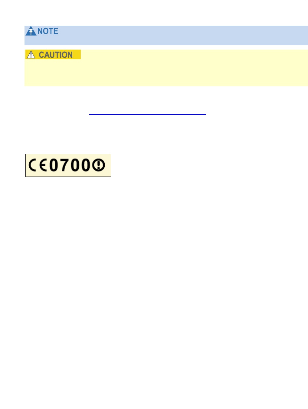
PTP 250 User Guide Notifications
phn-2182_003v004 (Oct 2011) UNDER DEVELOPMENT 4-17
Norway regulation is FOR2007-04-20 Nr 439 regarding border PFD limit.
This equipment operates as a secondary application, so it has no rights against harmful
interference, even if generated by similar equipment, and must not cause harmful
interference on systems operating as primary applications.
Hereby, Motorola Solutions, Inc. declares that the PTP 250 products comply with the essential
requirements and other relevant provisions of Directive 1999/5/EC. The declaration of conformity
may be consulted at http://www.motorola.com/ptp/support.
The European R&TTE directive 1999/5/EC Certification Number is reproduced on the
product label (Figure 4-3).
Figure 4-3 European Union certification on 5.8 GHz product label
The PTP 250 connectorized products have been notified for operation in those EU
countries that allow 5.8 GHz operation.

Notifications Chapter 4: Reference information
4-18 UNDER DEVELOPMENT phn-2182_003v004 (Oct 2011)

PTP 250 User Guide
phn-2182_003v004 (Oct 2011) UNDER DEVELOPMENT 5-1
Chapter 5: Installation
This chapter describes how to install the PTP 250 hardware,
To install the equipment at each PTP 250 link end, perform these tasks:
• Preparing for installation on page 5-2 describes the checks to be performed before
proceeding with the installation.
• Installing the ODU on page 5-4 describes how to install the ODU (integrated or
connectorized) on the supporting structure.
• Installing connectorized antennas on page 5-8 describes how to install separate
antenna(s) (only required for connectorized ODUs).
• Installing the drop cable and LPU on page 5-15 describes how to install the drop cable
from the ODU to the LPU and PoE power supply, and to provide grounding for the
installation.
• Installing the PoE power supply on page 5-29 describes how to install the PoE power
supply and connect it to the ODU and network cables.

Preparing for installation Chapter 5: Installation
5-2 UNDER DEVELOPMENT phn-2182_003v004 (Oct 2011)
Preparing for installation
This section describes the checks to be performed before proceeding with the installation.
Unit pre-configuration
It is common practice to pre-configure the units during staging before site installation by
performing the following tasks from Chapter 6: Configuration and alignment:
• Connecting to the unit on page 6-3
• Upgrading firmware version on page 6-10
• Using the installation wizard on page 6-13
If the units are to be pre-configured during staging, the safety precautions below MUST be
observed.
Safety precautions
All national and local safety standards must be followed while developing a site, installing
equipment, or performing maintenance.
Ensure that personnel are not exposed to unsafe levels of RF energy. The units
start to radiate as soon as they are powered up. Respect the safety standards
defined in Compliance with safety standards on page 4-8, in particular the
minimum separation distances.
Observe the following guidelines:
• Never work in front of the antenna when the ODU is powered.
• Always power down the PoE power supply when connecting and disconnecting the drop
cable from either the PoE power supply or ODU.
Protection requirements
The installation must meet the requirements defined in Grounding and lightning protection
on page 2-15.

PTP 250 User Guide Preparing for installation
phn-2182_003v004 (Oct 2011) UNDER DEVELOPMENT 5-3
Selecting installation options
Use the installation report to determine which installation options are required. Refer to
PTP LINKPlanner on page 2-10
Preparing personnel
IN NO EVENT SHALL MOTOROLA SOLUTIONS, INC. BE LIABLE FOR ANY INJURY TO
ANY PERSONS OR ANY DAMAGE CAUSED DURING THE INSTALLATION OF THE
MOTOROLA PTP 250.
Ensure that only qualified personnel undertake the installation of a PTP 250 link.
Ensure that all safety precautions can be observed.
Preparing inventory
Perform the following inventory checks:
• Check that an installation report is available and that it is based on the principles
described in Chapter 2: Planning considerations.
• Check that the correct components are available, as described in Ordering components
on page 2-24.
• Check the contents of all packages against their packing lists.
Preparing tools
Check that following specific tools are available, in addition to general tools:
• 13mm wrench and 22 mm wrench for use with the glands.
• RJ45 crimp tool (it must be the correct tool for the type of RJ45 being used).
• Personal Computer (PC) with 1000BaseT Ethernet.
• Web browser (for example Internet Explorer 7, Internet Explorer 8, Firefox 3 or Firefox
3.5).
• Ethernet patch cables.
Installing the ODU Chapter 5: Installation
5-4 UNDER DEVELOPMENT phn-2182_003v004 (Oct 2011)
Installing the ODU
Perform this task to install the ODU (integrated or connectorized) on the supporting
structure.
This task consists of the following procedures:
• Checks and safety precautions on page 5-4
• Selecting a position for the ODU (connectorized) on page 5-6
• Mounting the ODU on page 5-6
If a connectorized ODU is being installed, see also:
• Installing connectorized antennas on page 5-8
Checks and safety precautions
To prevent failure of the assembly, do not remove the mounting bracket, and do
not mount the ODU on a pole that is too narrow or too wide.
To minimize the risk of injury, do not attempt to hoist the ODU until the
necessary precautions have been taken.
To prevent failure of the assembly, do not over-tighten the bolts.
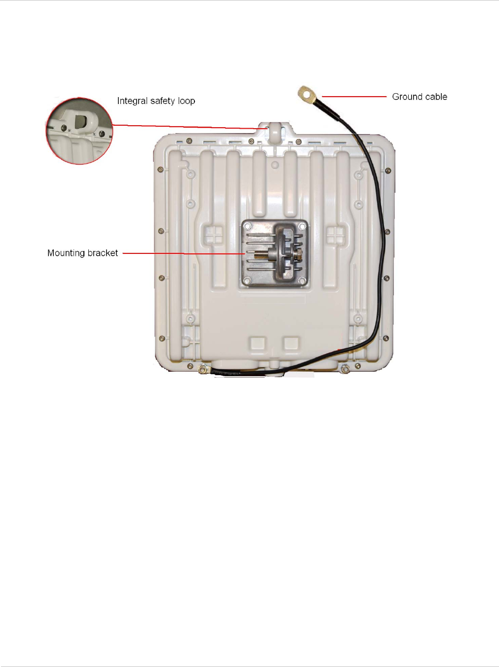
PTP 250 User Guide Installing the ODU
phn-2182_003v004 (Oct 2011) UNDER DEVELOPMENT 5-5
Check that the ODU is pre-fitted with a mounting bracket (designed to ease installation)
and with a ground cable (Figure 5-1).
Figure 5-1 Checking the ODU before mounting
Do not mount the ODU on poles with diameter less than 50mm (2”) or greater than 75mm
(3”). The ODU mounting bracket is designed to work only with poles with diameter in the
50 mm (2”) to 75 mm (3”) range.
Before hoisting the ODU, take the following precautions:
• Check that the safety loop (Figure 5-1) and its fixing are not damaged in any way and
have not been exposed to a shock loading due to a fall.
• Check that the safety lanyard does not exceed 1m (approx 3 ft) in length.
• Check that the safety lanyard is made from a material that does not degrade in an
outdoor environment.
• Check that the safety lanyard is fixed to a separate point that is not part of the direct
mounting system for the ODU.

Installing the ODU Chapter 5: Installation
5-6 UNDER DEVELOPMENT phn-2182_003v004 (Oct 2011)
Selecting a position for the ODU (connectorized)
If the ODU is connectorized, select a mounting position that gives it maximum protection
from the elements, but still allows easy access for connecting and weatherproofing the
cables. To minimize cable losses, select a position where the antenna cable lengths can be
minimized.
Mounting the ODU
To mount the ODU, proceed as follows:
1 Attach the ODU bracket strap to the pole using M8 x 70 mm bolts, M8 flat
washers and M8 coil washers.
Tighten to ensure the assembly grips, but can be adjusted on the pole.
2 Use the integral safety loop (Figure 5-1) to hoist the ODU up to the bracket,
observing the precautions described in Checks and safety precautions on page 5-
4.
3 When the ODU is in position, use the safety loop as a fixing point to secure a
permanent safety lanyard from the supporting structure to the ODU, as a
precaution against mounting failure.
4 Offer the ODU (with pre-fitted mounting bracket) to the bracket strap and affix
using the captive M8 bolt. Tighten to ensure the assembly grips, but can be
adjusted on the pole.
5 Adjust the elevation and azimuth of the unit to achieve an approximate visual
alignment (does not apply to connectorized ODUs). Tighten both bolts to the
required torque settings of 14 Nm (11 lb ft).

PTP 250 User Guide Installing the ODU
phn-2182_003v004 (Oct 2011) UNDER DEVELOPMENT 5-7
6 Connect the ODU ground cable to the to the supporting structure grounding
point, within 0.3 meters (1 ft) of the ODU bracket and on the same metal (if
necessary, remove paint and apply anti-oxidant compound first).
Do not attach grounding cables to the ODU mounting bracket bolts, as this
arrangement will not provide full protection.
7 To prevent corrosion and possible loss of ground continuity, weatherproof the
grounding point.

Installing connectorized antennas Chapter 5: Installation
5-8 UNDER DEVELOPMENT phn-2182_003v004 (Oct 2011)
Installing connectorized antennas
If the ODU is connectorized, perform this task to install separate antenna(s).
Preparing for connectorized installations
Before proceeding with the installation, perform the following checks:
• Check that the correct components are available, as described in Ordering components
on page 2-24.
• Check that the selected antenna conforms to the applicable regulatory restrictions, as
described in FCC approved antennas on page 2-30 and Compliance with radio
regulations on page 4-12.
• Check that the correct tools are available. The tools required for mounting the
antennas are specific to the antenna chosen. Refer to the antenna manufacturer’s
instructions.
Mounting and connecting antennas
To mount and connect the antenna(s), proceed as follows:
1 Mount the antenna(s) according to manufacturer’s instructions. When using
separate antennas to achieve spatial diversity, mount one with Horizontal
polarization and the other with Vertical polarization.
2 Connect the ODU to the antenna with cables of type LMR100, LMR200, LMR300,
LMR400 or LMR600. Connect the ODU ‘V’ interface to the vertical polarization
antenna and connect the ODU ‘H interface to the horizontal polarization antenna
(Figure 1-5).
When using separate antennas to achieve spatial diversity, the antenna cables
will be disconnected from the ODU during the alignment procedure. Therefore,
do not weatherproof the ODU joints until antenna alignment is complete.
3 Where the ODU is mounted indoors, install lightning arrestors at the building
entry point (Figure 5-2). Assemble the Polyphaser LSXL-ME or LSXL as shown in
Figure 5-3. Connect the lighting arrestors to the master ground bar of the
building.
4 When dressing the antenna cables, form drip loops near the lower ends. These
ensure that water is not constantly channeled towards the connectors.
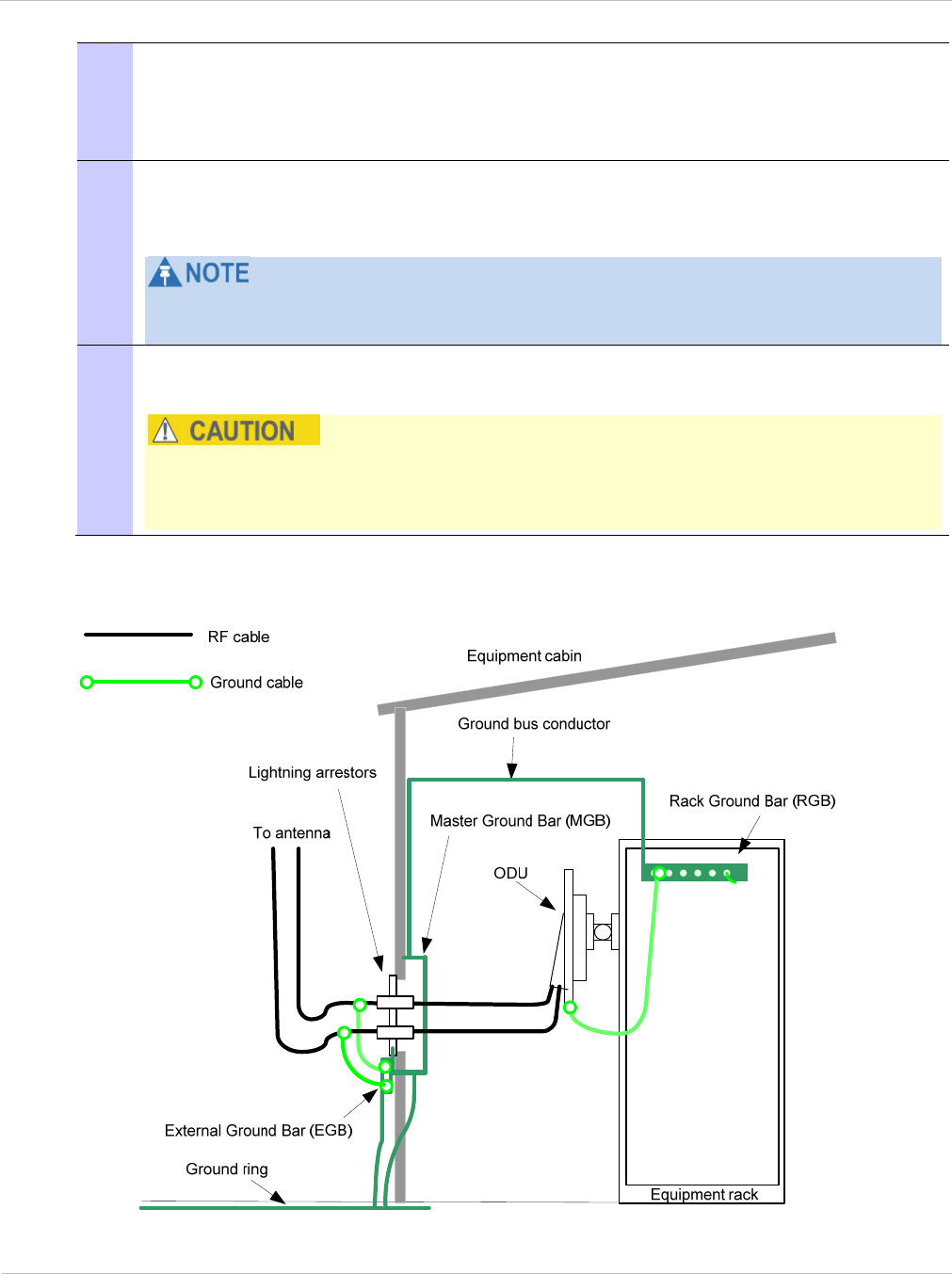
PTP 250 User Guide Installing connectorized antennas
phn-2182_003v004 (Oct 2011) UNDER DEVELOPMENT 5-9
5 If the ODU is mounted outdoors, weatherproof the N type connectors fitted to the
ODU by following the procedure Weatherproofing an N type connector on page 5-
12. Weatherproof the antenna joints in the same way (unless the antenna
manufacturer specifies a different method).
6 Ground the antenna cables to the supporting structure at the correct points
(Figure 5-4). They should be grounded within 0.3 meters (1 foot) of the ODU and
antennas using the using the cable grounding kit (part number 01010419001).
A mast or tower may require additional grounding points, as specified in
Protection requirements for a mast or tower installation on page 2-18.
7 Dress the antenna cables and attach them to the supporting structure using site
approved methods.
Ensure that no undue strain is placed on the ODU or antenna connectors. Ensure
that the cables do not flap in the wind, as flapping cables are prone to damage
and induce unwanted vibrations in the supporting structure.
Figure 5-2 Lightning arrestor mounting
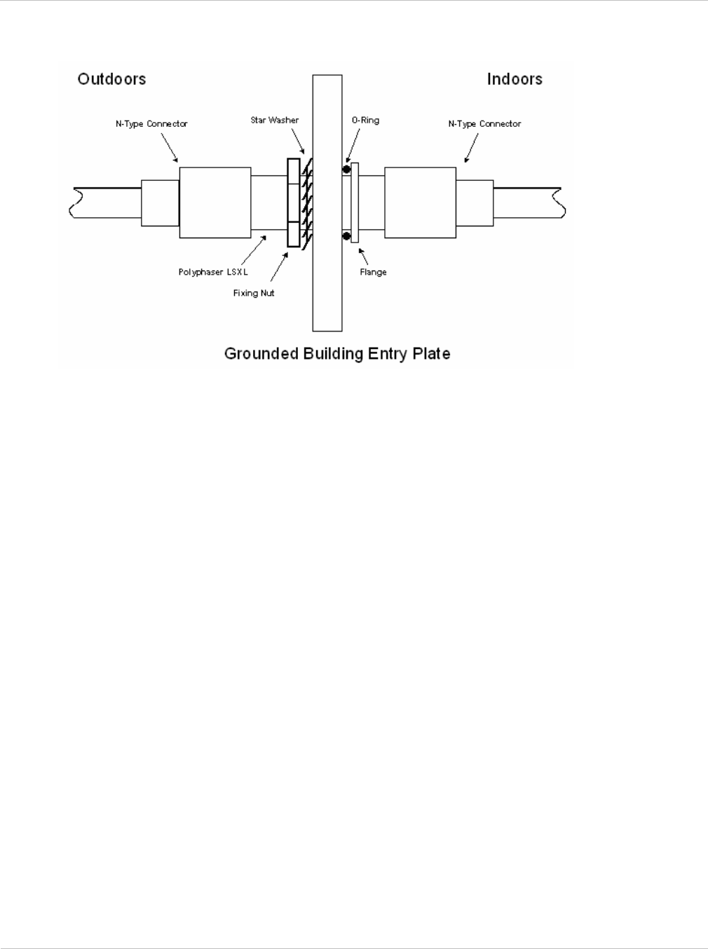
Installing connectorized antennas Chapter 5: Installation
5-10 UNDER DEVELOPMENT phn-2182_003v004 (Oct 2011)
Figure 5-3 Polyphaser assembly
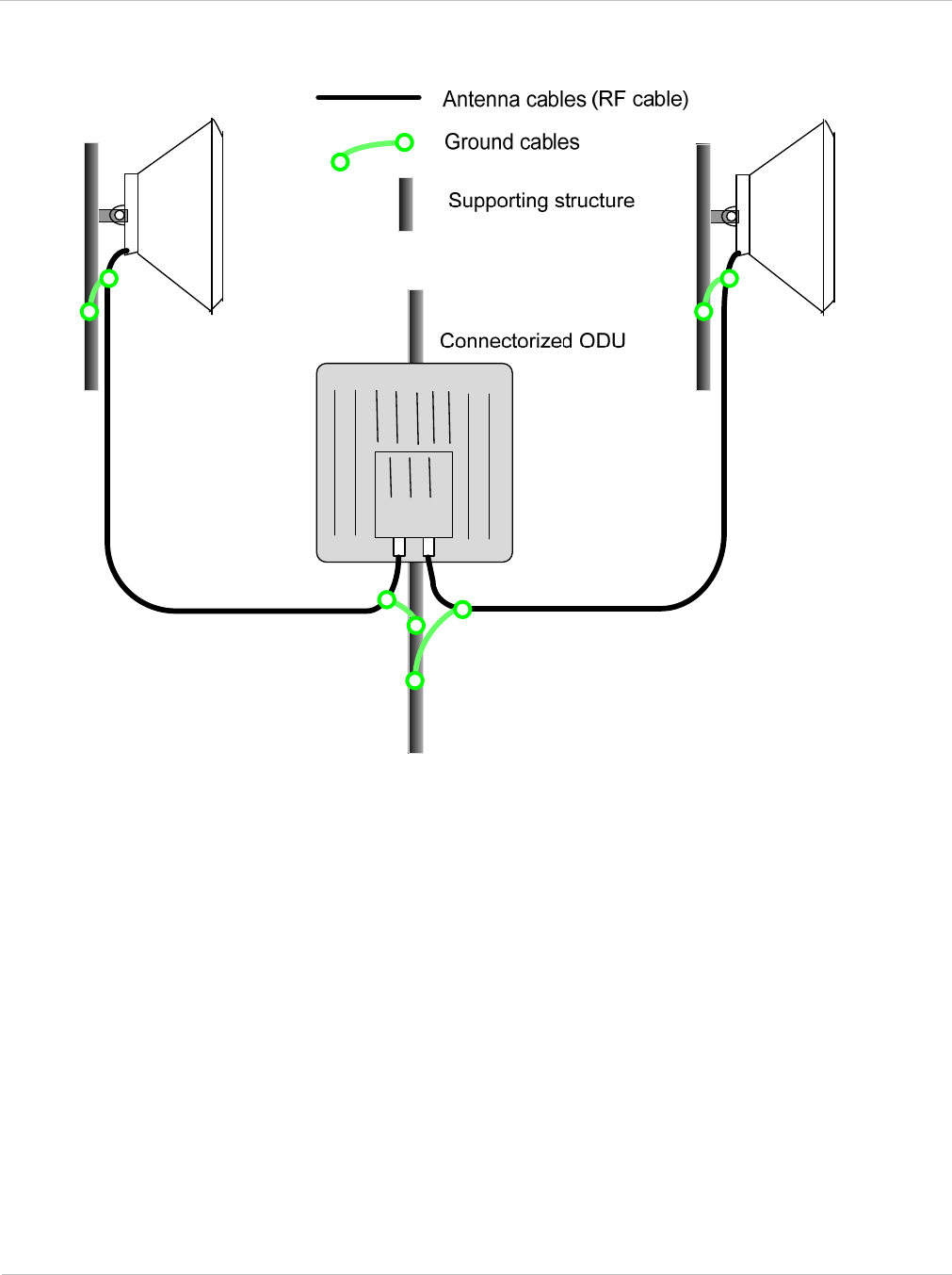
PTP 250 User Guide Installing connectorized antennas
phn-2182_003v004 (Oct 2011) UNDER DEVELOPMENT 5-11
Figure 5-4 Grounding points for antenna cables
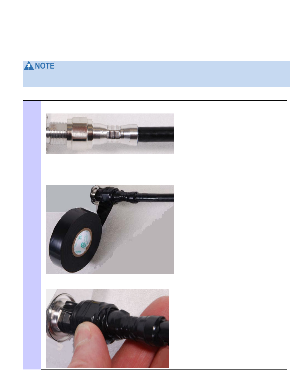
Installing connectorized antennas Chapter 5: Installation
5-12 UNDER DEVELOPMENT phn-2182_003v004 (Oct 2011)
Weatherproofing an N type connector
The following procedure should be used to weatherproof the N type connectors fitted to
the connectorized ODU and antenna (if recommended by the antenna manufacturer).
N type connectors should be tightened using a torque wrench, set to 15 lb in or 1.7 Nm. If
a torque wrench is not available, N type connectors may be finger tightened.
To weatherproof an N type connector, proceed as follows:
1 Ensure the connection is tight. A torque wrench should be used if available:
2 Wrap the connection with a layer of 19 mm (0.75 inch) PVC tape, starting 25 mm
(1 inch) below the connector body. Overlap the tape to half-width and extend the
wrapping to the body of the LPU. Avoid making creases or wrinkles:
3 Smooth tape edges:
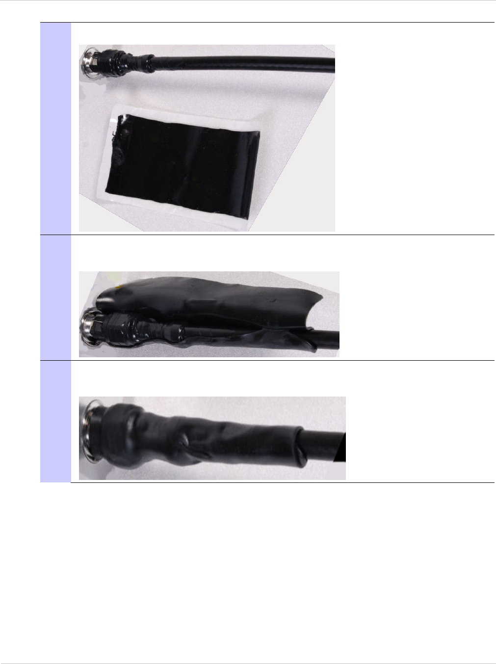
PTP 250 User Guide Installing connectorized antennas
phn-2182_003v004 (Oct 2011) UNDER DEVELOPMENT 5-13
4 Cut a 125mm (5 inches) length of rubber tape (self amalgamating):
5 Expand the width of the tape by stretching it so that it will wrap completely
around the connector and cable:
6 Press the tape edges together so that there are no gaps. The tape should extend
25mm (1inch) beyond the PVC tape:

Installing connectorized antennas Chapter 5: Installation
5-14 UNDER DEVELOPMENT phn-2182_003v004 (Oct 2011)
7 Wrap a layer of 50 mm (2 inch) PVC tape from bottom to top, starting from
25 mm (1 inch) below the edge of the self-amalgamating tape, overlapping at half
width.
8 Repeat with a further four layers of 19 mm (0.75 inch) PVC tape, always
overlapping at half width. Wrap the layers in alternate directions:
Second layer: top to bottom.
Third layer: bottom to top.
Fourth layer: top to bottom.
Fifth layer: bottom to top.
The bottom edge of each layer should be 25 mm (1 inch) below the previous
layer.
9 Completed weatherproof connection:
PTP 250 User Guide Installing the drop cable and LPU
phn-2182_003v004 (Oct 2011) UNDER DEVELOPMENT 5-15
Installing the drop cable and LPU
Perform this task to install the drop cable from the ODU to the PoE power supply, and to
provide grounding and lightning protection for the installation.
This task consists of the following procedures:
• Preparing drop cables on page 5-16.
• Assembling an RJ45 connector and gland on page 5-17.
• Installing and grounding the main drop cable on page 5-19.
• Connecting an RJ45 and gland to a unit on page 5-20.
• Disconnecting an RJ45 and gland from a unit on page 5-22.
• Making a drop cable ground point on page 5-23.
• Installing and grounding the drop cable at building entry on page 5-27.
The drop cable and ground cable installation must meet the requirements defined in
Grounding and lightning protection on page 2-15.
To provide effective protection against lightning induced surges, grounding cables must be
installed without drip loops and pointing down towards the ground.
To avoid damage to the installation, do not connect or disconnect the drop cable when
power is applied to the PoE power supply.
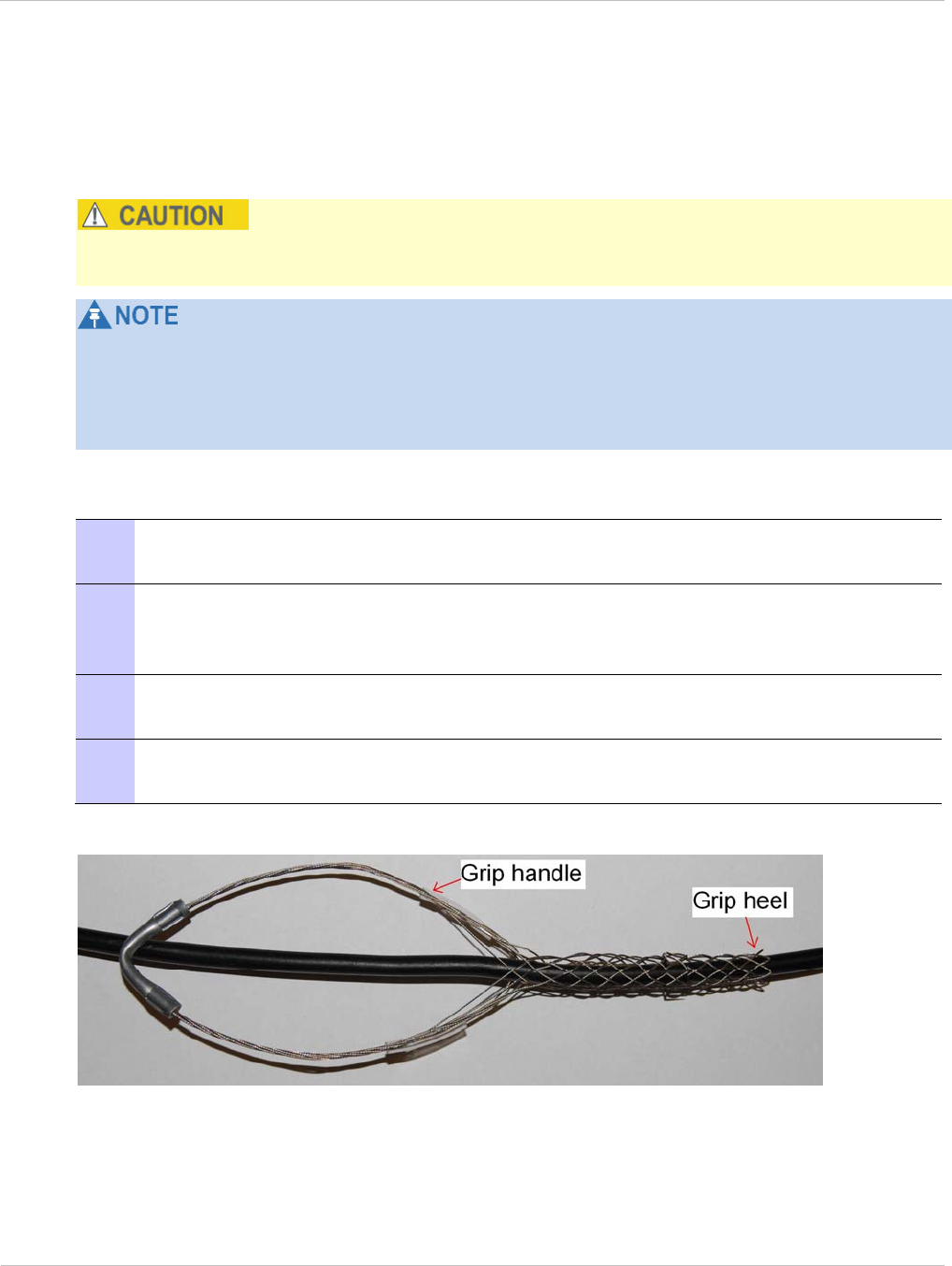
Installing the drop cable and LPU Chapter 5: Installation
5-16 UNDER DEVELOPMENT phn-2182_003v004 (Oct 2011)
Preparing drop cables
Perform this task to prepare the CAT5e cables that connect the ODU to the PoE power
supply.
Always use Cat5e cable that is gel-filled and shielded with copper-plated steel. Alternative
types of cable are not supported by Motorola.
The maximum permitted lengths of CAT5e cables are specified in Maximum cable lengths
on page 2-7.
For details of supported cables and recommended connectors, refer to Ordering
components on page 2-24.
‘Main’ drop cable: To prepare a long section of cable to connect the ODU to the LPU,
proceed as follows:
1 Cut off the approximate length required (allowing a bit of surplus), or leave it on
the drum so that it can be unwound as the cable is hoisted.
2 Slide one or more hoisting grips onto to the top end of the main drop cable
(Figure 5-5). To determine the number of hoisting grips required, consult the grip
manufacturer.
3 Secure the hoisting grip to the cable using a special tool, as recommended by the
manufacturer.
4 Fit an RJ45 connector and gland to the top end only, as described in Assembling
an RJ45 connector and gland on page 5-17.
Figure 5-5 Typical hoisting grip on cable
PTP 250 User Guide Installing the drop cable and LPU
phn-2182_003v004 (Oct 2011) UNDER DEVELOPMENT 5-17
‘LPU-PoE’ cable: To prepare a short section of cable to connect the LPU to the PoE power
supply, proceed as follows:
1 Cut off the approximate length required (allowing a bit of surplus).
2 Fit an RJ45 connector and gland to the top end only, as described in Assembling
an RJ45 connector and gland on page 5-17.
Assembling an RJ45 connector and gland
Perform this task to prepare the outdoor CAT5e cable with connectors and glands.
Safety precautions
The metal screen of the drop cable is very sharp and may cause personal injury.
When preparing the drop cable, take the following safety precautions:
• ALWAYS wear cut resistant gloves (check the label to ensure they are cut resistant).
• ALWAYS wear protective eyewear.
• ALWAYS use a rotary blade tool to strip the cable (DO NOT use a bladed knife). To use
the rotary blade tool, fit it around the outer cable sheath and rotate the cutter around
the cable once or twice. The stripped outer section can then be removed.
Assembly
Assemble the drop cable as shown in Figure 5-6. The gland is only required for outdoor
connections at the ODU or LPU. The connection to the PoE power supply requires the RJ45
plug but no gland.
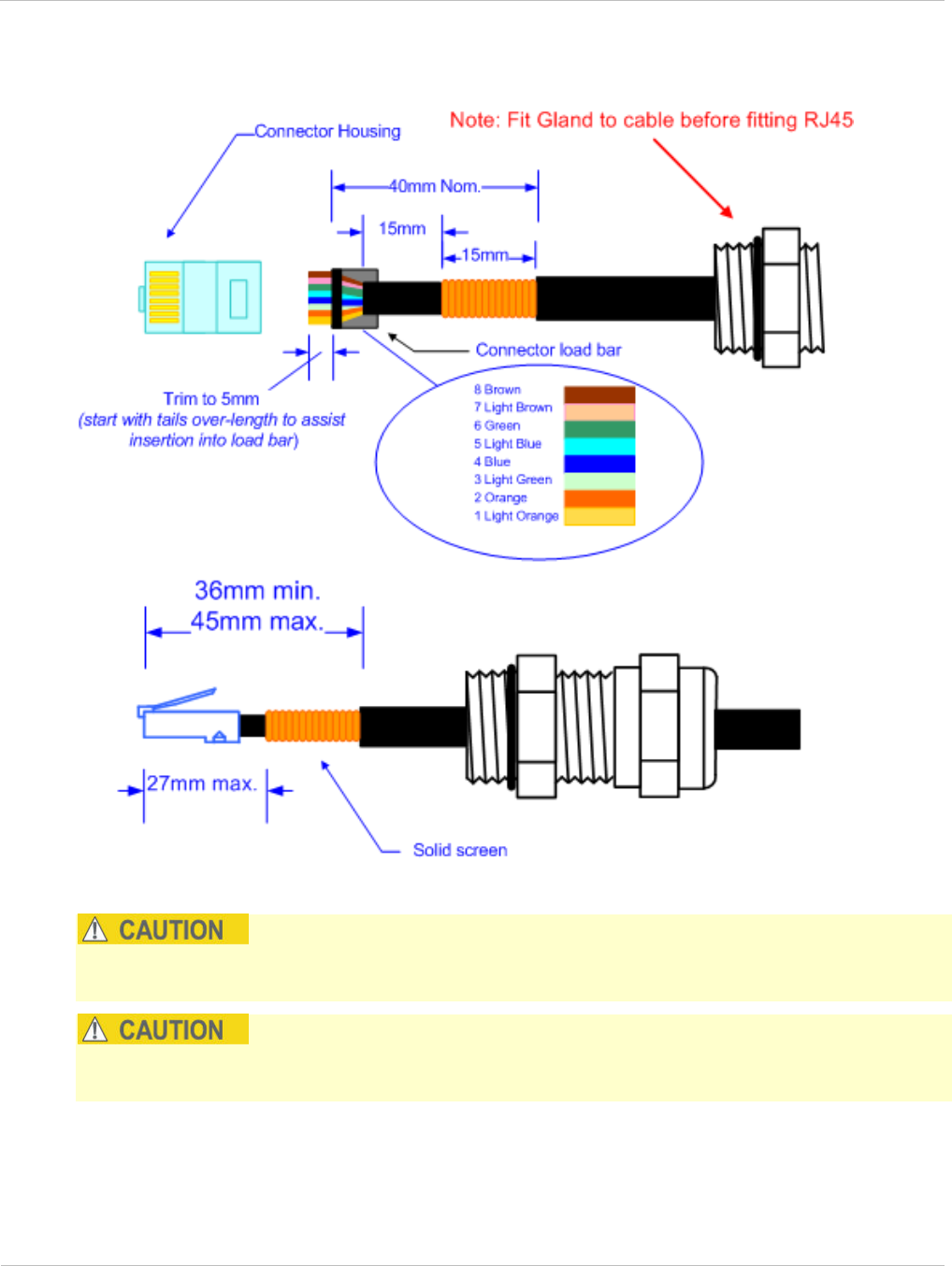
Installing the drop cable and LPU Chapter 5: Installation
5-18 UNDER DEVELOPMENT phn-2182_003v004 (Oct 2011)
Figure 5-6 Correct cable preparation for drop cable of the supported type
Check that the crimp tool matches the RJ45 connector being used; otherwise the cable or
connector may be damaged.
The cable inner sheath must be located correctly under the connector housing tang. If this
is not done correctly, there is no strain relief on the cable terminations.
Figure 5-7 shows the end of a drop cable fitted with an RJ45 plug and a gland.

PTP 250 User Guide Installing the drop cable and LPU
phn-2182_003v004 (Oct 2011) UNDER DEVELOPMENT 5-19
Figure 5-7 Drop cable with RJ45 and gland
Installing and grounding the main drop cable
Perform this procedure to install the main drop cable, connect it to the ODU, and ground it
to the supporting structure.
To install and ground the main drop cable, proceed as follows:
1 Hoist the main drop cable up to the ODU using the hoisting grip and a hoist line.
When the cable is in position and the grip handle is fastened to the supporting
structure, remove the hoist line.
2 Connect the top end of the long drop cable to the ODU (PoE port), as described in
Connecting an RJ45 and gland to a unit on page 5-20.
3 Lay the main drop cable as far as the building entry point, ensuring there is
enough length to extend through the wall of the building to the LPU.
4 Attach the main drop cable to the supporting structure using site approved
methods.
5 Ground the drop cable to the supporting structure at the points shown in Figure
2-3 (mast or tower installation) or Figure 2-4 (wall installation), as described in
Making a drop cable ground point on page 5-23.
A mast or tower may require additional grounding points, as specified in
Protection requirements for a mast or tower installation on page 2-18.
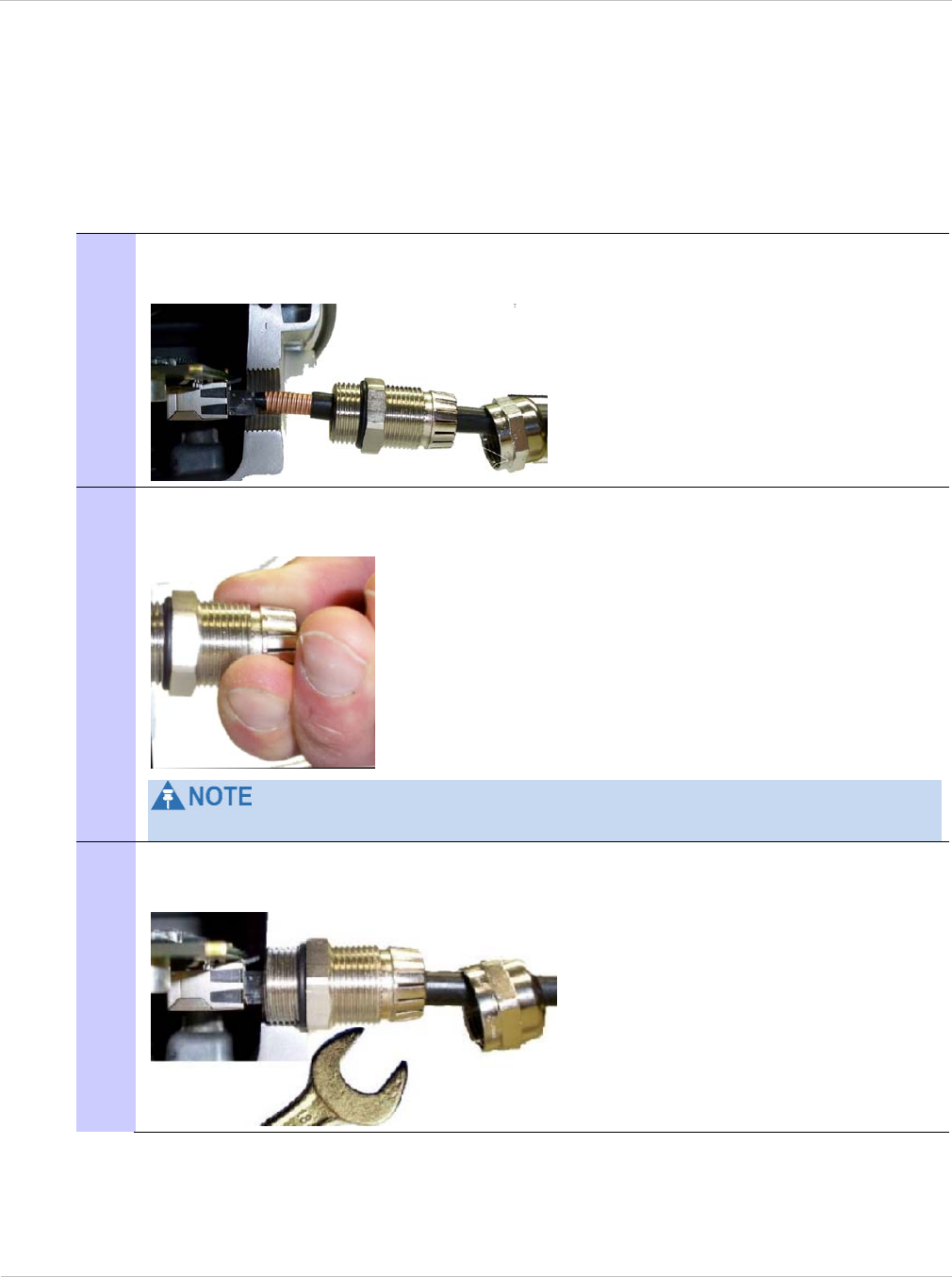
Installing the drop cable and LPU Chapter 5: Installation
5-20 UNDER DEVELOPMENT phn-2182_003v004 (Oct 2011)
Connecting an RJ45 and gland to a unit
Perform this task to connect the drop cable to an ODU or LPU. This procedure contains
illustrations of an ODU, but it applies in principle to both the ODU and the LPU.
To connect the drop cable with a gland to a unit (LPU or ODU), proceed as follows:
1 Insert the RJ45 plug into the socket in the unit, making sure that the locking tab
snaps home.
2 Support the drop cable and gently hand screw the gland body into the unit until
the O ring seal is flush to the unit body.
Do not fit the back shell prior to securing the gland body.
3 Once the gland is fully hand screwed into the unit, tighten it with a spanner to
torque 10 Nm (7.4 ftlbs).
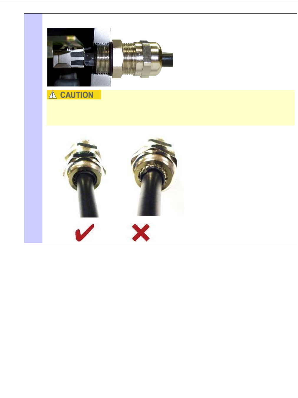
PTP 250 User Guide Installing the drop cable and LPU
phn-2182_003v004 (Oct 2011) UNDER DEVELOPMENT 5-21
4 When the gland body has been fitted, tighten the gland back shell.
Do not over-tighten the gland back shell, as the internal seal and structure may
be damaged. The following example shows correctly tightened and over-tightened
gland back shells:

Installing the drop cable and LPU Chapter 5: Installation
5-22 UNDER DEVELOPMENT phn-2182_003v004 (Oct 2011)
Disconnecting an RJ45 and gland from a unit
Perform this task to disconnect the drop cable from an ODU or LPU. This procedure
contains illustrations of an ODU, but it applies in principle to both the ODU and the LPU.
To disconnect the drop cable with a gland from a unit (LPU or ODU), proceed as follows:
1 Remove the gland back shell.
2 Wiggle the drop cable to release the tension of the gland body.
When the tension in the glad body is released, a gap opens at the point shown in
red in the above photograph.
3 Unscrew the gland body.
4 Use a small screwdriver to depress the RJ45 locking tab.
5 Unplug the RJ45.
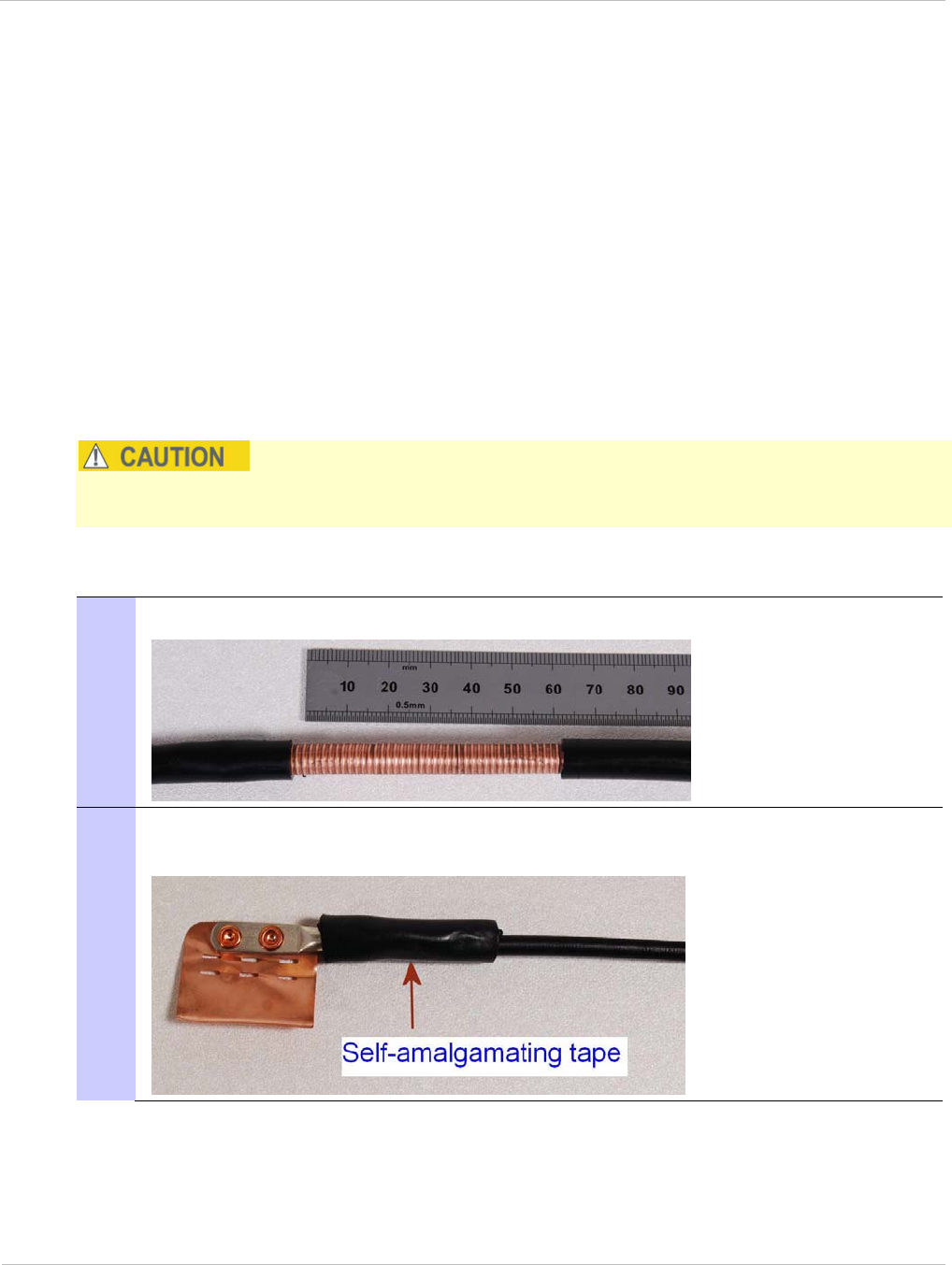
PTP 250 User Guide Installing the drop cable and LPU
phn-2182_003v004 (Oct 2011) UNDER DEVELOPMENT 5-23
Making a drop cable ground point
Perform this task to connect the screen of the drop cable to the metal of the supporting
structure using a cable grounding kit.
The cable grounding kit for 1/4” and 3/8” cable (Figure 1-8) contains the following
components:
• 1 x grounding cable with grounding 2 hole lug fitted (M10)
• 1 x self Amalgamating tape
• 1 x PVC tape
• 3 x tie wraps
• 2 x bolt, washer and nut
Ground cables must be installed without drip loops and pointing down towards the ground;
otherwise they may not be effective.
To ground the drop cable to a metal structure using the Motorola grounding kit (part
number 01010419001), proceed as follows:
1 Remove 60 mm (2.5 inches) of the drop cable outer sheath.
2 Cut 38mm (1.5 inches) of rubber tape (self amalgamating) and fit to the ground
cable lug. Wrap the tape completely around the lug and cable.
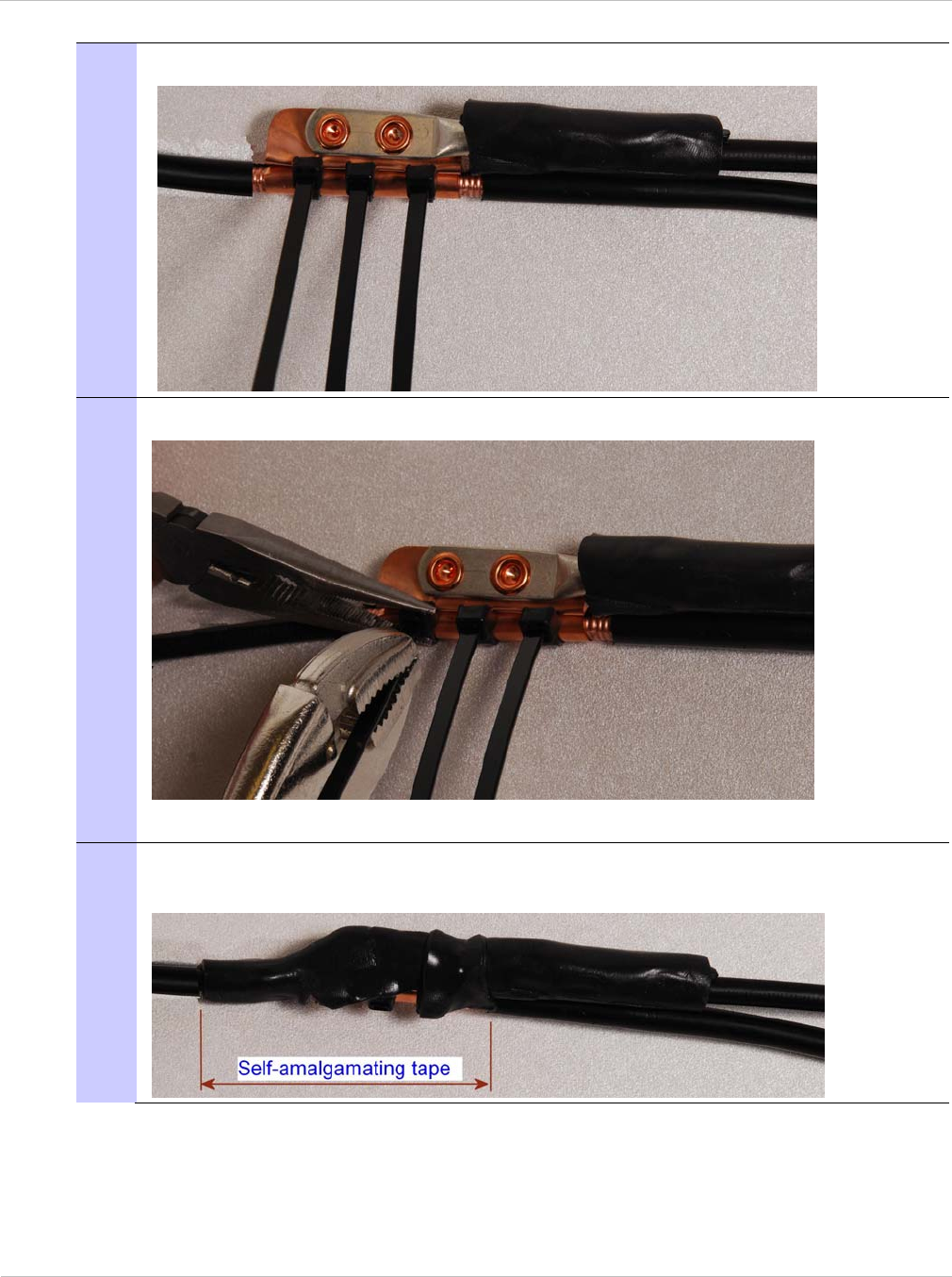
Installing the drop cable and LPU Chapter 5: Installation
5-24 UNDER DEVELOPMENT phn-2182_003v004 (Oct 2011)
3 Fold the ground wire strap around the drop cable screen and fit cable ties.
4 Tighten the cable ties with pliers.
Cut the surplus from the cable ties.
5 Cut a 38mm (1.5 inches) section of self-amalgamating tape and wrap it
completely around the joint between the drop and ground cables.

PTP 250 User Guide Installing the drop cable and LPU
phn-2182_003v004 (Oct 2011) UNDER DEVELOPMENT 5-25
6 Use the remainder of the self-amalgamating tape to wrap the complete assembly.
Press the tape edges together so that there are no gaps.
7 Wrap a layer of PVC tape from bottom to top, starting from 25 mm (1 inch) below
and finishing 25 mm (1 inch) above the edge of the self-amalgamating tape, over
lapping at half width.
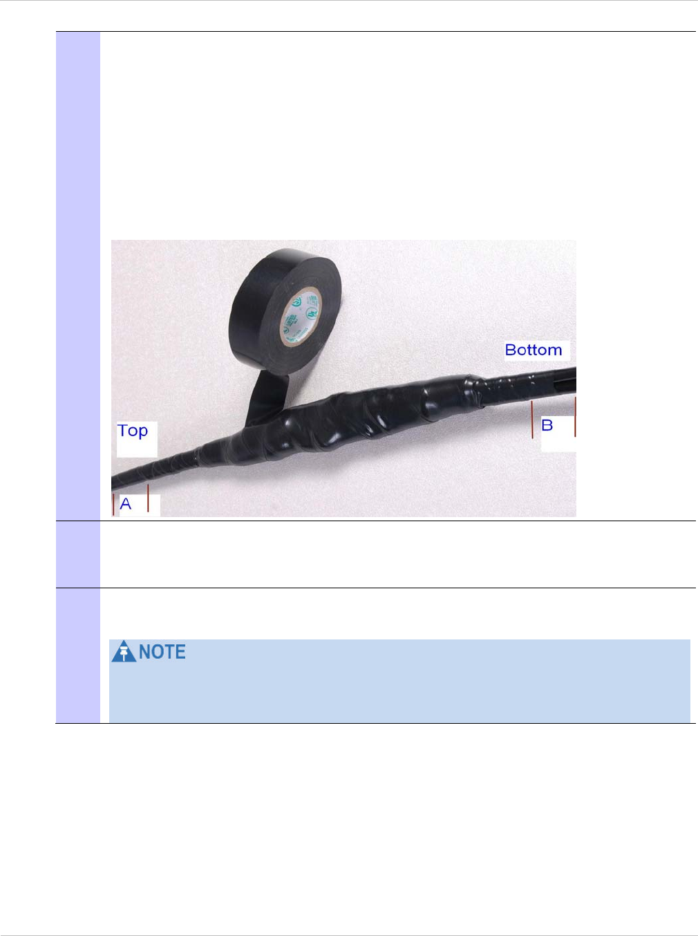
Installing the drop cable and LPU Chapter 5: Installation
5-26 UNDER DEVELOPMENT phn-2182_003v004 (Oct 2011)
8 Repeat with a further four layers of PVC tape, always overlapping at half width.
Wrap the layers in alternate directions:
Second layer: top to bottom.
Third layer: bottom to top.
Fourth layer: top to bottom.
Fifth layer: bottom to top.
The edges of each layer should be 25mm (1 inch) above (A) and 25 mm (1 inch)
below (B) the previous layer.
9 Prepare the metal grounding point of the supporting structure to provide a good
electrical contact with the grounding cable clamp. Remove paint, grease or dirt,
if present. Apply anti-oxidant compound liberally between the two metals.
10 Clamp the bottom lug of the grounding cable to the supporting structure using
site approved methods.
The manual
R56 Standards And Guidelines For Communication Sites
states that
two-hole lugs secured with fasteners in both holes are preferred over single-hole
lugs.
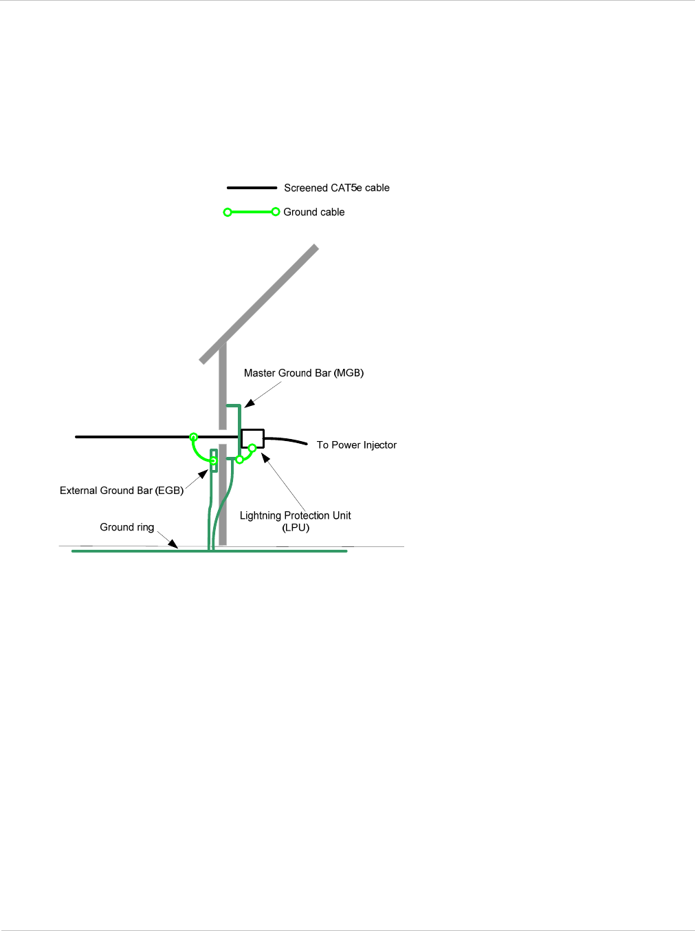
PTP 250 User Guide Installing the drop cable and LPU
phn-2182_003v004 (Oct 2011) UNDER DEVELOPMENT 5-27
Installing and grounding the drop cable at building entry
Perform this procedure to install and ground the drop cable and LPU at the building (or
cabinet) entry point (Figure 5-8).
Figure 5-8 Grounding at building entry

Installing the drop cable and LPU Chapter 5: Installation
5-28 UNDER DEVELOPMENT phn-2182_003v004 (Oct 2011)
To run the drop cable into the building, proceed as follows:
1 Make an entry point into the building and run the main drop cable into the
building.
2 Ground the drop cable to the external ground bar outside the building entry
point, as described in Making a drop cable ground point on page 5-23.
3 Install the LPU inside the building, not more than 600 mm (24 in) from the
building entry point. Mount the LPU with cable glands facing downwards.
4 Ground the LPU to the master ground bar.
5 Cut any surplus length from the bottom end of the main drop cable and fit an
RJ45 connector and gland, as described in Assembling an RJ45 connector and
gland on page 5-17.
6 Connect the main drop cable to the LPU, as described in Connecting an RJ45 and
gland to a unit on page 5-20.
7 Connect the LPU-PoE cable to the other port of the LPU, as described in
Connecting an RJ45 and gland to a unit on page 5-20.
8 Run the LPU-PoE cable to the location of the PoE power supply.
If it is necessary to disconnect the drop cable, refer to Disconnecting an RJ45 and gland
from a unit on page 5-22.

PTP 250 User Guide Installing the PoE power supply
phn-2182_003v004 (Oct 2011) UNDER DEVELOPMENT 5-29
Installing the PoE power supply
Perform this task to install the PoE power supply, connect it to the ODU, and prepare the
network cables.
If the PIDU is to be installed rather than the PoE power supply, refer to the
PTP 300 and
PTP 500 Series User Guide
(available for download at www.motorola.com/ptp/software) for
PIDU installation instructions.
This task consists of the following procedures:
• Preparing for PoE power supply installation on page 5-29
• Mounting the PoE power supply on page 5-30
• Connecting the PoE power supply to the drop cable on page 5-31
• Preparing the PoE power supply to network equipment cable on page 5-32
Preparing for PoE power supply installation
The PoE power supply can be installed free standing, on an even horizontal surface or wall
mounted using wall mounting key holes on the underside of the unit. The following
guidelines should be adhered to before cabling the PoE power supply to the Ethernet
source and ODU:
• Verify the device receiving power and Ethernet from the PoE power supply is a PTP
250 ODU.
• Do not block or cover airflow to the PoE power supply.
• Keep the PoE power supply away from excessive heat, humidity, vibration and dust.
• The PoE power supply is not a repeater, and does not amplify the Ethernet data signal.
Do not configure the cable length between the Ethernet network source, the PoE
power supply and the PTP 250 ODU beyond 100 meters (333ft).
The PoE power supply is not waterproof and should be mounted away from sources of
moisture. If mounted outdoors, the unit should be mounted in a moisture proof enclosure,
preferably ventilated.
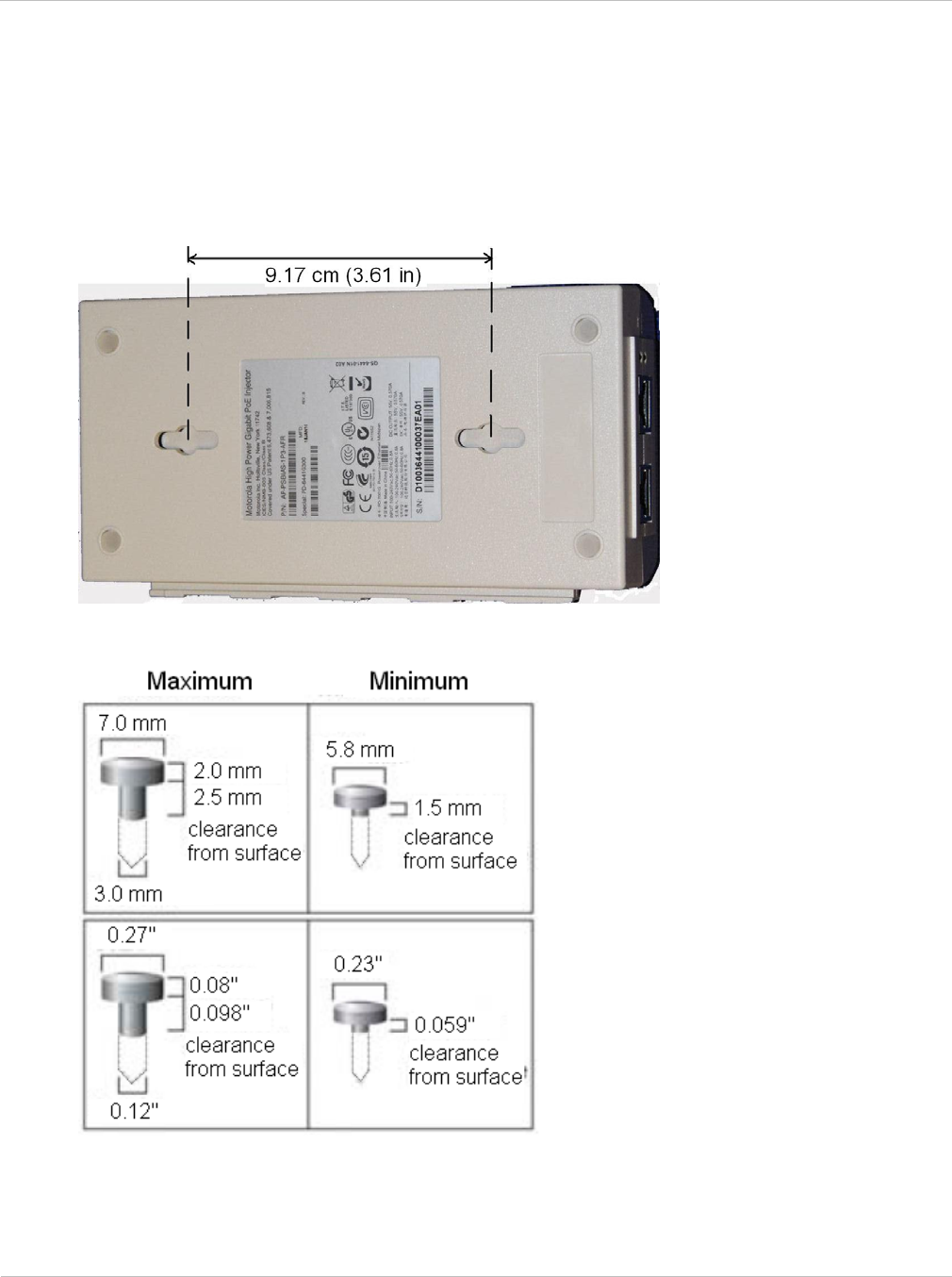
Installing the PoE power supply Chapter 5: Installation
5-30 UNDER DEVELOPMENT phn-2182_003v004 (Oct 2011)
Mounting the PoE power supply
To mount the PTP 250 PoE power supply: install two screws (Table 5-1) in the wall or shelf,
then align the mounting slots (Figure 5-9) to capture the surface screws.
Figure 5-9 Mounting slots on underside of PoE power supply
Table 5-1 Screw dimensions for the PoE power supply
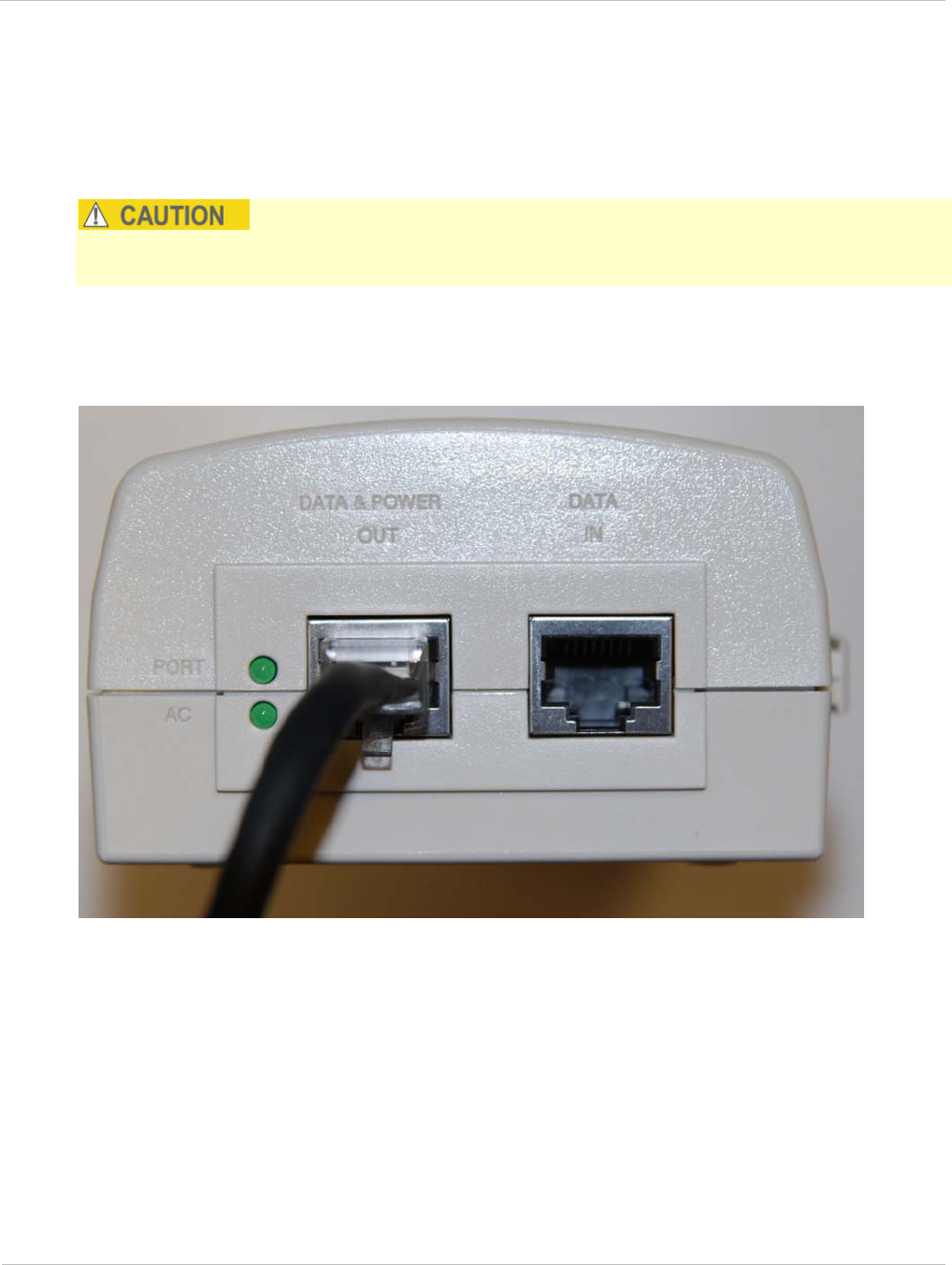
PTP 250 User Guide Installing the PoE power supply
phn-2182_003v004 (Oct 2011) UNDER DEVELOPMENT 5-31
Connecting the PoE power supply to the drop cable
The drop cable from the ODU is connected to the DATA & POWER OUT interface of the
PoE power supply.
Do not dress the PoE power supply cables too tightly, as this may make the connections
unreliable.
Fit an RJ45 connector (but no gland) to the PoE end of the LPU-PoE cable. Connect the
cable to the DATA & POWER OUT interface of the PoE power supply.
Figure 5-10 PoE power supply connected to LPU-PoE cable

Installing the PoE power supply Chapter 5: Installation
5-32 UNDER DEVELOPMENT phn-2182_003v004 (Oct 2011)
Preparing the PoE power supply to network equipment cable
Prepare the CAT5e cable that will connect the PoE power supply to the network
equipment. This cable must meet the following requirements:
• Use either foil screen (FTP) or braided screen (STP) cable.
• Use screened RJ45 connectors with metal shells at both ends.
• Ensure there is a continuous electrical connection between both screened connectors.
The connected network equipment must feature screened RJ45 connectors and must be
connected to ground, otherwise the PoE power supply will not be grounded.
The PoE power supply is not normally connected to the network equipment until antenna
alignment is complete. See Connecting to the network on page 6-34.

PTP 250 User Guide
phn-2182_003v004 (Oct 2011) UNDER DEVELOPMENT 6-1
Chapter 6: Configuration and alignment
This chapter describes all configuration and alignment tasks that are performed when a
PTP 250 link is deployed.
Before proceeding with unit configuration and antenna alignment, observe the precautions
described in Preparing for configuration and alignment on page 6-2.
Configure the two units, one as ‘Master’ and the other as ‘Slave’ by performing the
following tasks:
• Connecting to the unit on page 6-3 describes how to connect a PC to the unit, power it
up and open the web interface.
• Upgrading firmware version on page 6-10 describes how to ensure that the latest
firmware version is installed on the unit.
• Using the installation wizard on page 6-13 describes how to configure the LAN,
wireless, date and email attributes of the unit.
When all equipment has been installed at both link ends, perform the following tasks:
• Aligning antennas on page 6-23 describes how to align integrated and connectorized
antennas.
• Connecting link to the network on page 6-30 describes how to review link performance
and connect to the network.
• Saving the system configuration on page 6-35 describes when and how to save the
system configuration to file.

Preparing for configuration and alignment Chapter 6: Configuration and alignment
6-2 UNDER DEVELOPMENT phn-2182_003v004 (Oct 2011)
Preparing for configuration and alignment
This section describes the checks to be performed before proceeding with unit
configuration and antenna alignment.
Safety precautions during configuration and alignment
All national and local safety standards must be followed while configuring the units and
aligning the antennas.
Ensure that personnel are not exposed to unsafe levels of RF energy. The units
start to radiate as soon as they are powered up. Respect the safety standards
defined in Compliance with safety standards on page 4-8, in particular the
minimum separation distances.
Observe the following guidelines:
o Never work in front of the antenna when the ODU is powered.
o Always power down the PoE power supply (or PIDU) before connecting or
disconnecting the drop cable from either the power supply, ODU or LPU.
Regulatory compliance during configuration and alignment
All applicable radio regulations must be followed while configuring the units and aligning
the antennas. For more information, refer to Compliance with radio regulations on page 4-
12.
Selecting configuration options
Use the installation report to determine which configuration options are required. Refer to
Chapter 2: Planning considerations.

PTP 250 User Guide Connecting to the unit
phn-2182_003v004 (Oct 2011) UNDER DEVELOPMENT 6-3
Connecting to the unit
Perform this task to connect a management PC to the unit, power it up and open the web
interface.
This task consists of the following procedures:
• Configuring the management PC on page 6-3
• Connecting to the PC and powering up on page 6-5
• Logging into the web interface on page 6-6
Configuring the management PC
Install Java on the management PC (if not already installed), as this is used by the PTP 250
web interface.
To configure the local management PC to communicate with the PTP 250, proceed as
follows:
1 Select Properties for the Ethernet port.
2 Select the Internet Protocol (TCP/IP) item as shown in Figure 6-1.
3 Click on Properties.
4 Enter an IP address that is valid for the 169.254.X.X network, avoiding:
169.254.0.0 and 169.254.1.1 and 169.254.1.2
A good example is 169.254.1.3 (Figure 6-2).
5 Enter a subnet mask of 255.255.0.0.
Leave the default gateway blank.
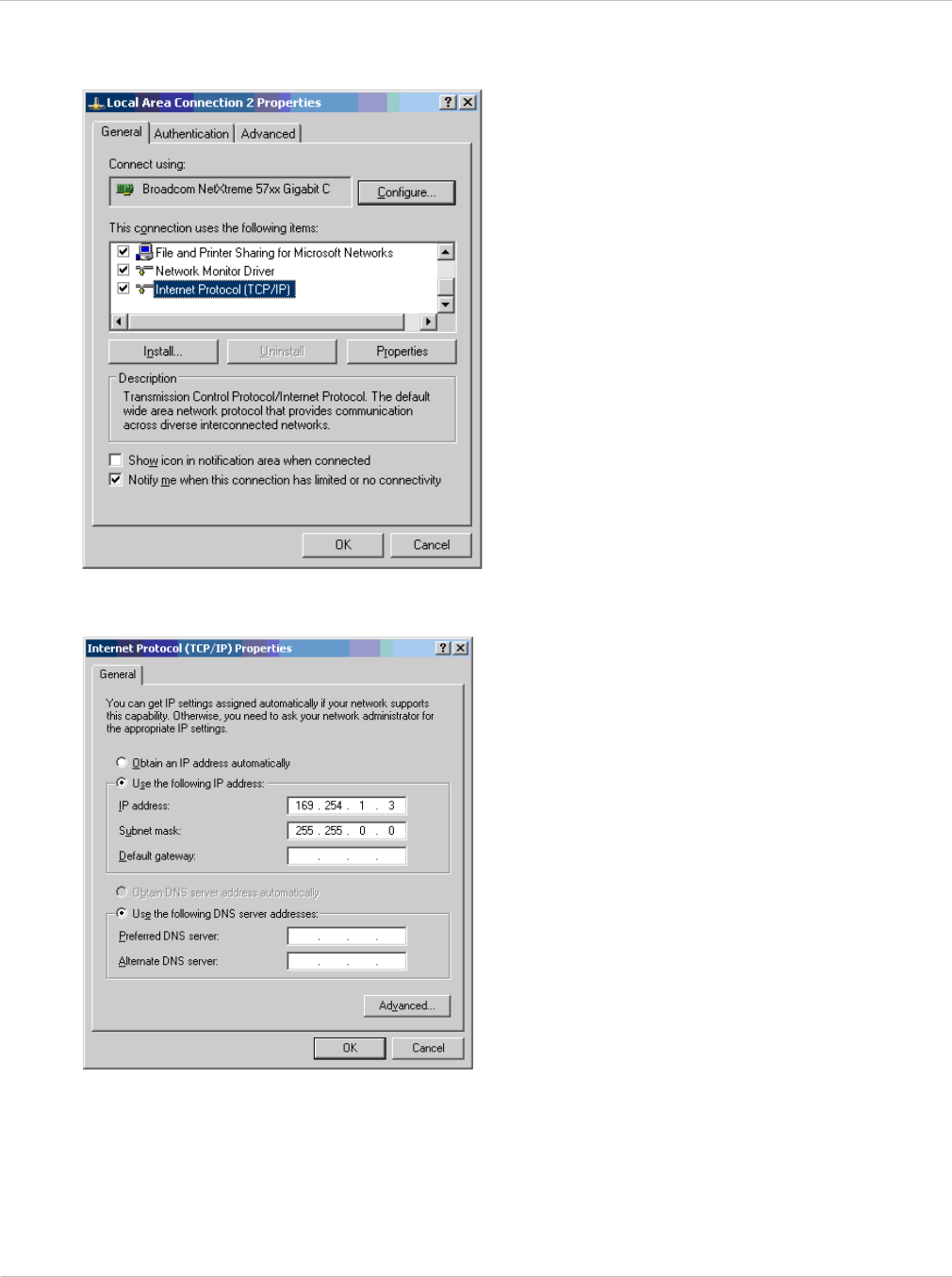
Connecting to the unit Chapter 6: Configuration and alignment
6-4 UNDER DEVELOPMENT phn-2182_003v004 (Oct 2011)
Figure 6-1 IP configuration on the PC
Figure 6-2 Internet Protocol (TCP/IP) Properties page
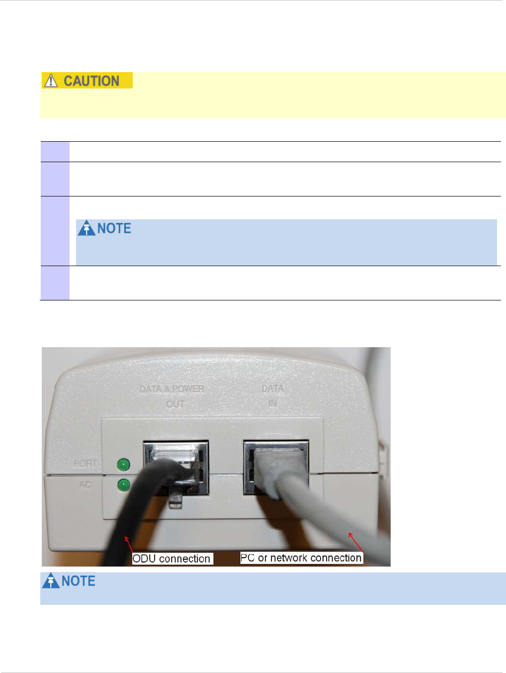
PTP 250 User Guide Connecting to the unit
phn-2182_003v004 (Oct 2011) UNDER DEVELOPMENT 6-5
Connecting to the PC and powering up
Ensure AC power is supplied to the PoE power supply using an AC cable with an
appropriate ground connection approved for the country of operation.
To connect the ODU to the PC and power up the unit, proceed as follows:
1 Check that the ODU and PoE power supply are correctly connected.
2 Connect the PC Ethernet port to the DATA IN port of the PoE power supply using
a standard (not crossed) Cat5e cable (Figure 6-3).
3 Connect the PoE power supply to an AC outlet (100 V AC to 240 V AC).
The PoE power supply has no power switch. It supplies power to the ODU as soon
as AC power is applied.
4 Check that the AC and PORT LEDs illuminate (green steady). If they blink or do
not illuminate, refer to Testing link end hardware on page 8-2.
Figure 6-3 PoE power supply connected to ODU and PC (or network)
If the power supply is a PIDU, the Ethernet LED does not illuminate.

Connecting to the unit Chapter 6: Configuration and alignment
6-6 UNDER DEVELOPMENT phn-2182_003v004 (Oct 2011)
Logging into the web interface
To log into the web interface as a system administrator, proceed as follows:
1 Start the web browser from the management PC.
2 Type the IP address of the unit (factory default is 169.254.1.1) into the address
bar. Press ENTER.
For user security, Motorola digitally signs its applications. On the first login, the
digital signature confirmation is displayed (Figure 6-4). Tick the ‘Always trust
content from this publisher’ box and select Run.
The digitally signed Java app splash screen is displayed (Figure 6-5), followed by
the Login page.
3 When the Login page is displayed (Figure 6-6), enter the Username ‘admin’ and
Password (default ‘motorola’) and select Login.
4 On the first login to a new unit, or on the first login to a unit that has been reset
to full or partial default configuration, the Change Password page is displayed
(Figure 6-7). Enter and confirm the new Password.
5 On the first login to a new unit, or on the first login to a unit that has been reset
to full default configuration, the Set Country Code page is displayed (Figure 6-8).
Select the Country Code and select OK to confirm it is correct.
Ensure the correct Country Code is selected. An incorrect selection may result in
illegal radio operation. Once set, the Country Code can only be changed by using
the reset switch, as described in Resetting to default configuration (with country
reset) on page 7-26.
6 The web interface menu and System Summary page are displayed (Figure 6-9).
Continue with configuration.

PTP 250 User Guide Connecting to the unit
phn-2182_003v004 (Oct 2011) UNDER DEVELOPMENT 6-7
Figure 6-4 Digital signature confirmation (on first login)
Figure 6-5 Digitally signed Java app splash screen
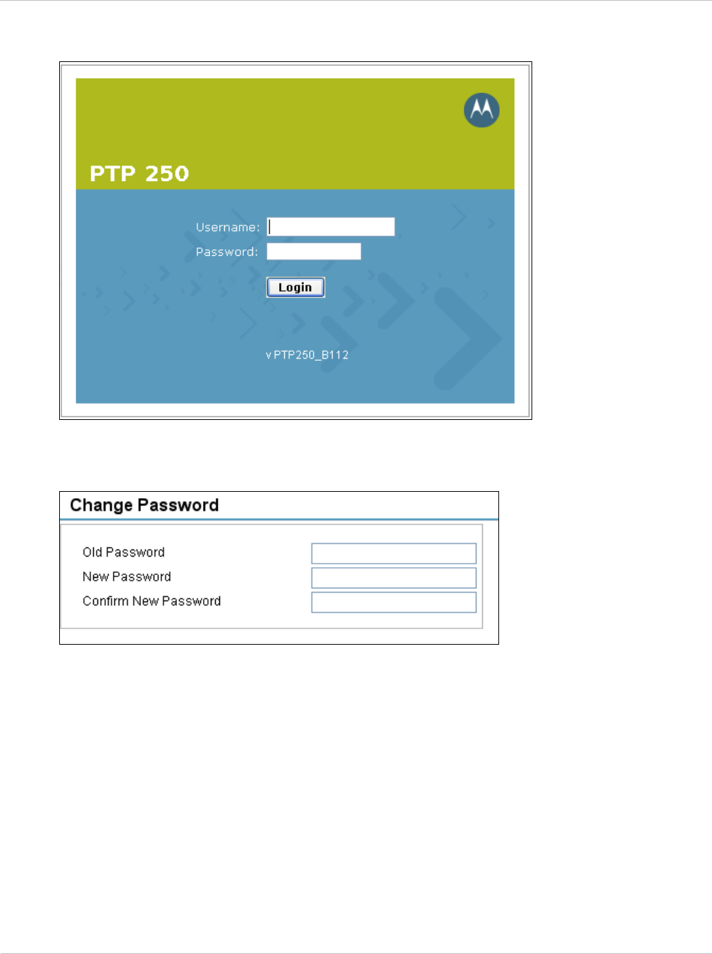
Connecting to the unit Chapter 6: Configuration and alignment
6-8 UNDER DEVELOPMENT phn-2182_003v004 (Oct 2011)
Figure 6-6 Login page
Figure 6-7 Change Password page (on first login)
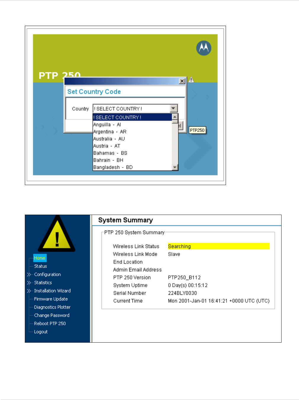
PTP 250 User Guide Connecting to the unit
phn-2182_003v004 (Oct 2011) UNDER DEVELOPMENT 6-9
Figure 6-8 Set Country Code page (on first login)
Figure 6-9 Menu and System Summary page (on first login)
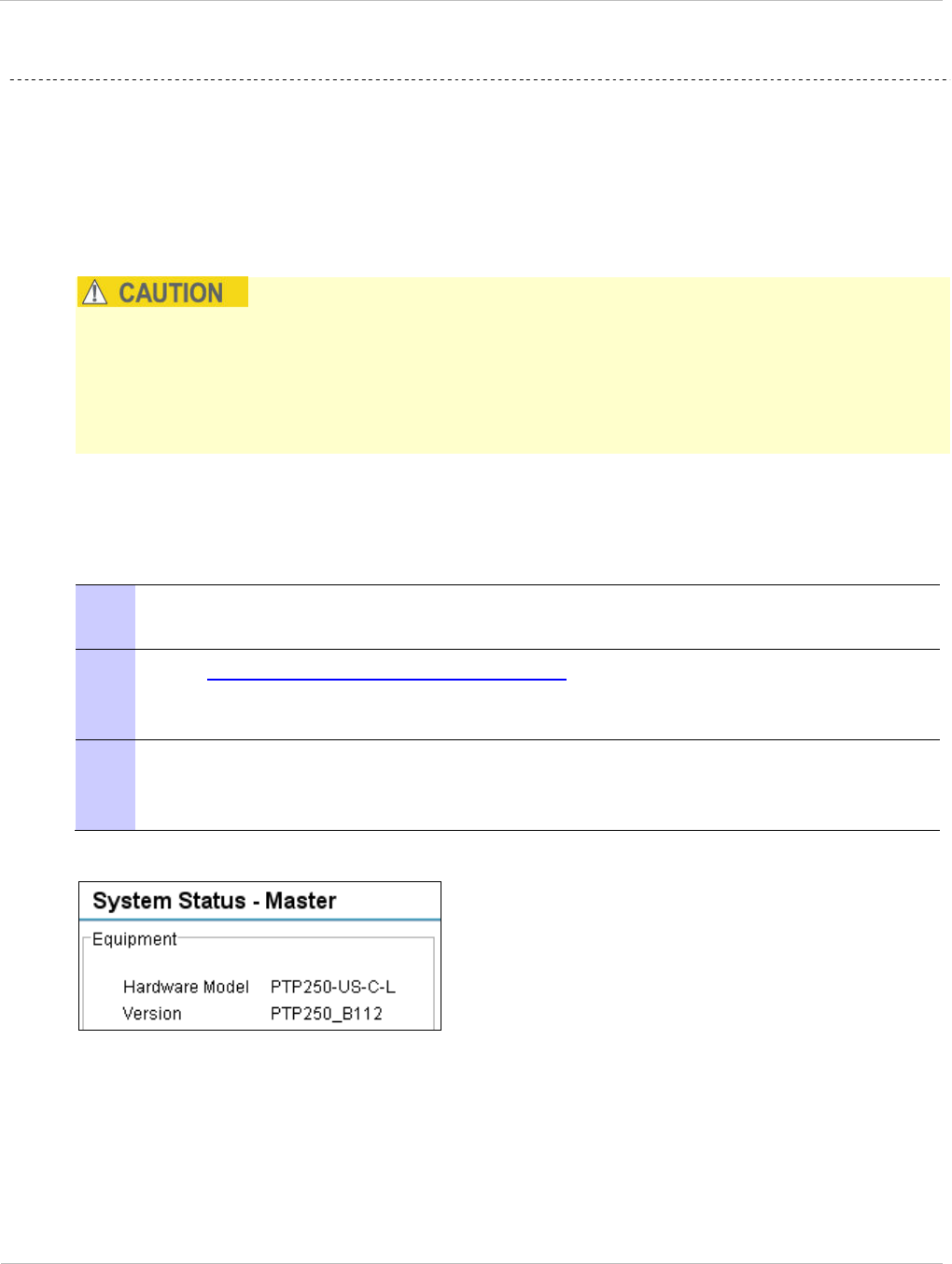
Upgrading firmware version Chapter 6: Configuration and alignment
6-10 UNDER DEVELOPMENT phn-2182_003v004 (Oct 2011)
Upgrading firmware version
Perform this task to ensure that the latest firmware version is installed on the unit.
This task consists of the following procedures:
• Checking the installed firmware version on page 6-10
• Uploading a new firmware version on page 6-11
Ensure that the correct units are upgraded, as units cannot easily be downgraded
afterwards.
If the link is operational, ensure that the remote end of the link is upgraded first using the
wireless connection, and then the local end can be upgraded. Otherwise, the remote end
may not be accessible.
Checking the installed firmware version
To check that the latest firmware version is installed, proceed as follows:
1 Select menu option Status. The System Status page is displayed. The Version
attribute near the top left is the installed firmware version (Figure 6-10).
2 Go to http://www.motorola.com/ptp/support and find Point-to-Point software
updates. Check that the latest available firmware version (for example 250-04-01)
is the same as the one already installed.
3 If the unit needs to be upgraded to the latest firmware version, perform Saving
the system configuration on page 6-35 and Uploading a new firmware version on
page 6-11.
Figure 6-10 Firmware Version in System Status page

PTP 250 User Guide Upgrading firmware version
phn-2182_003v004 (Oct 2011) UNDER DEVELOPMENT 6-11
Uploading a new firmware version
To upload a new firmware version, proceed as follows:
1 Save the pre-upgrade system configuration as described in Saving the system
configuration on page 6-35.
2 Go to http://www.motorola.com/ptp/support and find Point-to-Point software
updates. Download and save the required firmware image (for example PTP250-
04-01.bin).
3 Select menu option Firmware Update. The Firmware Update page is displayed
(Figure 6-11).
4 Select the Method. The default is HTTP.
If FTP or TFTP is selected, additional attributes are displayed and must be
completed.
5 Select Browse. Navigate to the folder containing the downloaded firmware
image and select Open.
6 Select Start Firmware Upload and Yes to confirm. The upload progress is
displayed. On completion, the Upload Successful page is displayed (Figure 6-12).
To ensure that only authorized Motorola firmware is installed, the unit checks the
image for a DSA signature. If the DSA signature is missing or incorrect, an error
message is displayed and the upload fails.
7 Select Apply and Reboot.
8 The reboot process will take up to 120 seconds. During this time it will not be
possible to communicate with the unit. After the reboot, check that the required
firmware image is loaded and running.
9 Save the post-upgrade system configuration as described in Saving the system
configuration on page 6-35.
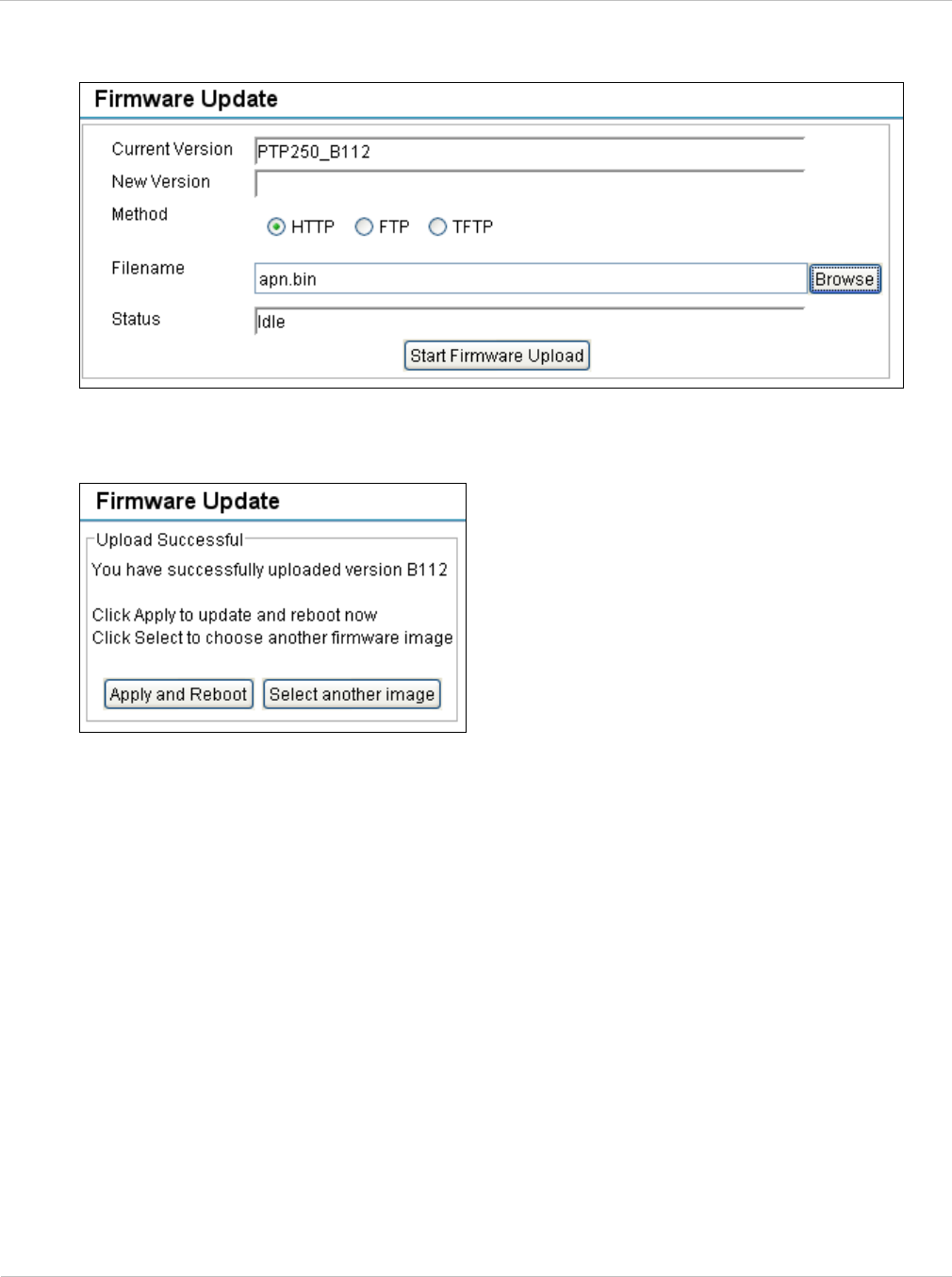
Upgrading firmware version Chapter 6: Configuration and alignment
6-12 UNDER DEVELOPMENT phn-2182_003v004 (Oct 2011)
Figure 6-11 Firmware Update page
Figure 6-12 Upload Successful page
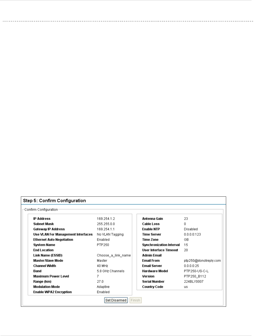
PTP 250 User Guide Using the installation wizard
phn-2182_003v004 (Oct 2011) UNDER DEVELOPMENT 6-13
Using the installation wizard
Perform this task to configure the LAN, wireless, date and email attributes of the unit.
This task consists of the following procedures:
• Starting installation wizard on page 6-13
• Step 1: LAN configuration on page 6-14
• Step 2: Wireless configuration on page 6-16
• Step 3: Date and time settings on page 6-18
• Step 4: Email configuration on page 6-21
• Step 5: Confirm installation configuration on page 6-22
Starting installation wizard
To start the installation wizard, select menu option Installation Wizard. The response
depends upon the state of the unit:
• If the unit is armed for alignment, the Step 5: Confirm Configuration page is displayed
(Figure 6-13). Select Set Disarmed, Yes to confirm and then Back until the Step 1:
LAN Configuration page is displayed.
• If the unit is not armed, the Step 1: LAN Configuration page is displayed.
Figure 6-13 Step 5: Confirm Configuration page (when unit is armed)
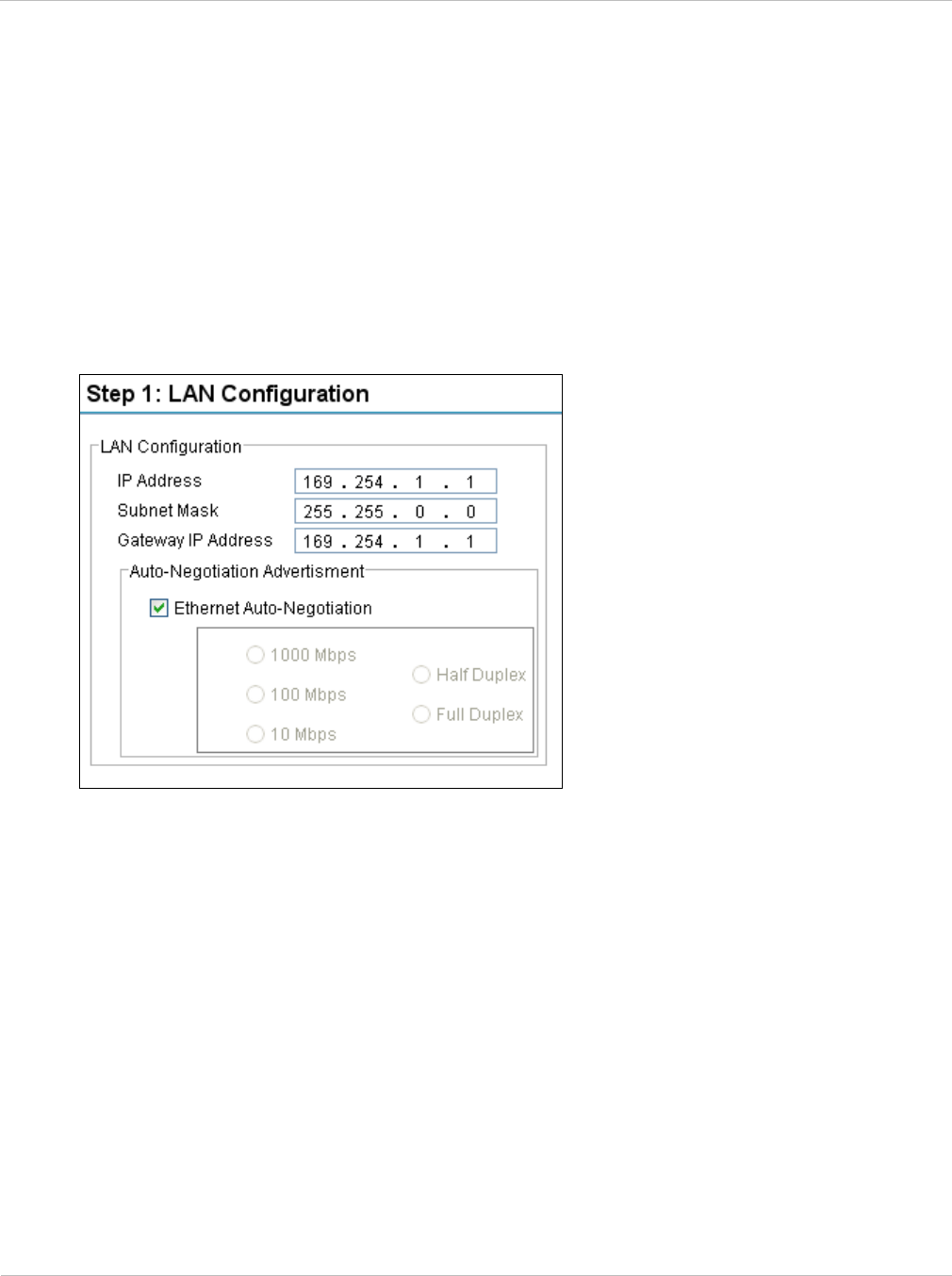
Using the installation wizard Chapter 6: Configuration and alignment
6-14 UNDER DEVELOPMENT phn-2182_003v004 (Oct 2011)
Step 1: LAN configuration
Step 1 of the Installation wizard is for updating the LAN configuration (Figure 6-14). The
attributes are described in Table 6-1.
Update IP Address, Subnet Mask and Gateway IP Address to meet network requirements
(as specified by the network administrator). Update the other attributes as required and
select Next.
Figure 6-14 Step 1: LAN Configuration page

PTP 250 User Guide Using the installation wizard
phn-2182_003v004 (Oct 2011) UNDER DEVELOPMENT 6-15
Table 6-1 Step 1: LAN Configuration attributes
Attribute Meaning
IP Address Internet protocol (IP) address. This address is used by the family
of Internet protocols to uniquely identify this unit on a network.
All units are shipped with a default IP address of 169.254.1.1.
Change this default IP address to ensure that: (a) it is unique on
the network, and (b) the Master and Slave units have different IP
addresses.
Subnet Mask Defines the address range of the connected IP network.
Gateway IP Address The IP address of a computer on the current network that acts as
a gateway. A gateway acts as an entrance and exit to packets
from and to other networks.
Ethernet Auto-
Negotiation
When the box is ticked, it means that configuration is
automatically negotiated. This is the default setting.
When the box is not ticked, it means that configuration is forced.
Select the data rate that the auto-negotiation mechanism will
advertise as available.
Only select a data rate that is within the capability of connected
network equipment, otherwise loss of service may occur.
Use the same setting for both ends of the link.
The configuration should only be forced if problems are
experienced with auto-negotiation.
Instead of forcing configuration, the IEEE802.3 specification
recommends enabling Auto-Negotiation with only the specific
ability or abilities advertised.
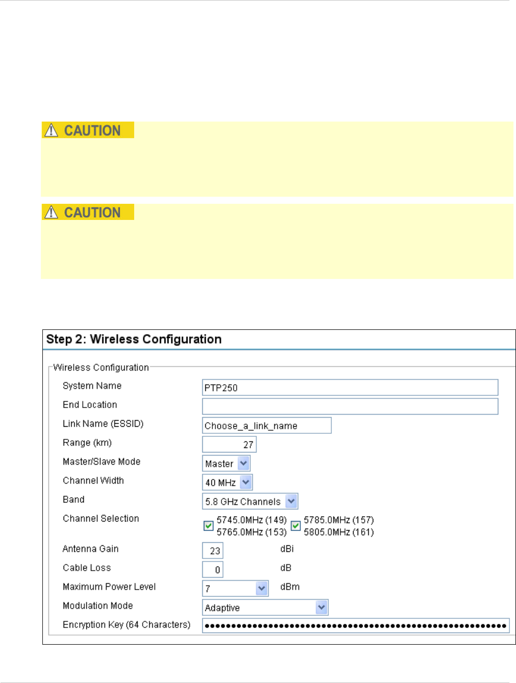
Using the installation wizard Chapter 6: Configuration and alignment
6-16 UNDER DEVELOPMENT phn-2182_003v004 (Oct 2011)
Step 2: Wireless configuration
Step 2 of the Installation wizard is for updating the wireless configuration (Figure 6-15).
The attributes are described in Table 6-2. Update the attributes as required and select
Next.
To comply with FCC rules, unselect any channels that may interfere with TDWR radars.
This must be done before the units are allowed to radiate on site. The system designer will
have provided a list of any affected channels, based on the instructions in Avoidance of
weather radars (USA only) on page 2-5.
When operating with external antennas in countries that impose an EIRP limit, choose an
external antenna and RF cable that will not cause the PTP 250 to exceed the EIRP limit,
based on the instructions in Calculating maximum power level for connectorized units on
page 2-13.
Figure 6-15 Step 2: Wireless Configuration page

PTP 250 User Guide Using the installation wizard
phn-2182_003v004 (Oct 2011) UNDER DEVELOPMENT 6-17
Table 6-2 Step 2: Wireless Configuration attributes
Attribute Meaning
System Name A name for the link. Spaces are not allowed, so use underscores
instead.
End Location The location of the link end. Spaces are not allowed, so use
underscores instead.
Link Name (ESSID) A link can only be established between units that have identical
Link Names.
Link Name may consist of letters (A-Z and a-z), numbers (0-9)
and the following special characters (no spaces):
(),-.,:<=>[]_{}
Range (km) The link range. The value must not be less than the actual
distance between the link ends.
Master/Slave Mode Each link consists of one ‘Master’ and one ‘Slave’ unit. The
Master is used to control and maintain the point-to-point link.
The Master transmits until the link is made, while the Slave
listens for its Master and only transmits when the Master has
been identified.
As all units are shipped with a default setting of ‘Slave’, one unit
in the link must be reset to ‘Master’.
Channel Width Width (MHz) of the radio channel used by this link. The selection
depends upon the frequency variant and country of operation.
This can only be updated at the Master unit.
Band The frequency band (GHz) in which this link operates.
This can only be updated at the Master unit.
Channel Selection The channel (MHz) in which this link operates. This can only be
updated at the Master unit.
If Channel Width is set to 40 MHz, then each tick box selects two
20 MHz channels: the first is Current Channel and the second is
Extended Channel.
If the system designer has provided a list of channels that may
interfere with TDWR radars, ensure they are unselected.
Antenna Gain Gain (dBi) of the antenna that is connected to this unit. See FCC
approved antennas on page 2-30.

Using the installation wizard Chapter 6: Configuration and alignment
6-18 UNDER DEVELOPMENT phn-2182_003v004 (Oct 2011)
Attribute Meaning
Cable Loss Loss (dB) in the RF cable between the ODU and the antenna.
If there is a significant difference in length of the antenna cables
for the two antenna ports, then enter the average value.
Maximum Power
Level
The maximum power (dBm) at which the unit will transmit.
The highest value in the list is automatically constrained to be
within regulatory limts, based on the values entered in Antenna
Gain and Cable Loss.
Modulation Mode The modulation mode used on the transmit channel. The
recommended setting is ‘Adaptive’.
Encryption Key
(64 characters)
Key to be used for link encryption. The same key must be used at
both ends of the link.
Step 3: Date and time settings
Step 3 of the Installation wizard is for setting the date and time (Figure 6-16). The
attributes are described in Table 6-3. Update the attributes as required and select Next.
The clock supplies accurate date and time information to the system. It can be set to run
with or without a connection to a Network Time Protocol (NTP) server:
• In the absence of an NTP server connection, the clock can be set to run manually. The
clock is battery backed and will continue to operate for several days after the ODU is
switched off.
• If an NTP server connection is available, the clock can be set to synchronize with the
server time at regular intervals.
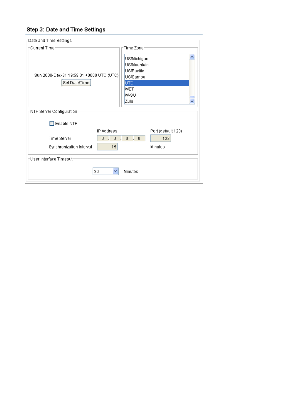
PTP 250 User Guide Using the installation wizard
phn-2182_003v004 (Oct 2011) UNDER DEVELOPMENT 6-19
Figure 6-16 Step 3: Date and Time Settings page

Using the installation wizard Chapter 6: Configuration and alignment
6-20 UNDER DEVELOPMENT phn-2182_003v004 (Oct 2011)
Table 6-3 Step 3: Date and Time Settings attributes
Attribute Meaning
Current Time The current date and time setting for this unit.
To update this, select Set Date/Time.
Time Zone The time zone in which this unit operates.
Enable NTP If this is ticked, the PTP 250 will obtain accurate date and time
updates from a networked time server.
Time Server IP
Address
The IP address of the networked NTP server.
Time Server Port The port number of the networked NTP server. By convention
the default value is 123.
Synchronization
Interval
The interval at which the PTP 250 requests time correction
updates from the NTP server. If a request fails, the PTP 250
automatically performs three retries before waiting for the next
Synchronization Interval.
User Interface
Timeout
The time that is allowed to pass without user activity before the
user is logged out.
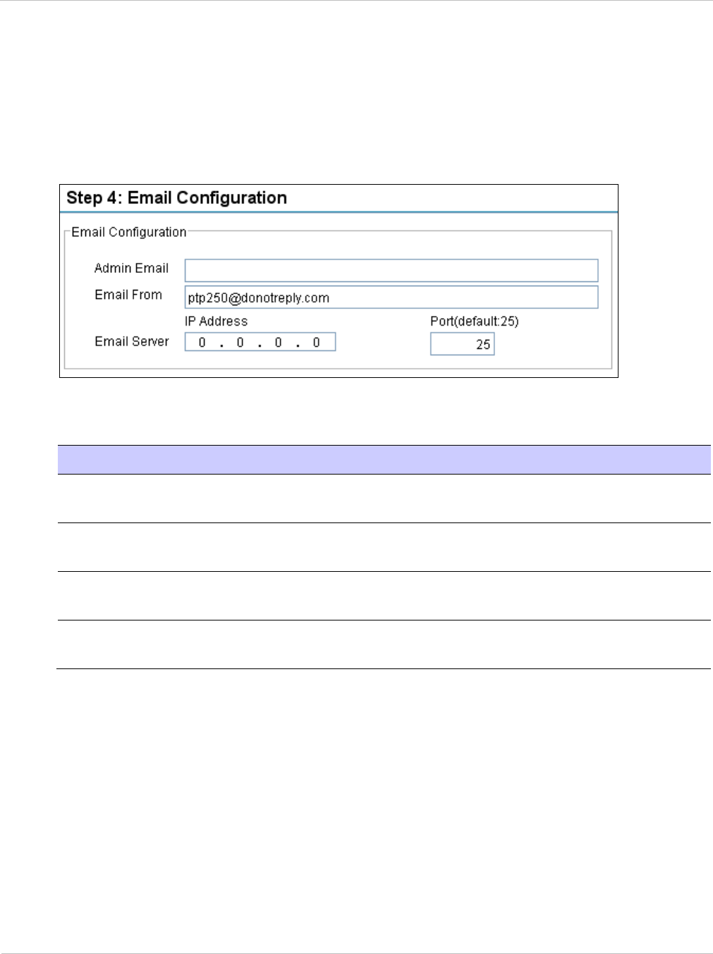
PTP 250 User Guide Using the installation wizard
phn-2182_003v004 (Oct 2011) UNDER DEVELOPMENT 6-21
Step 4: Email configuration
Step 4 of the Installation wizard is for configuring email notifications (Figure 6-17). The
attributes are described in Table 6-4. Update the attributes as required and select Next.
Figure 6-17 Step 4: Email Configuration page
Table 6-4 Step 4: Email Configuration attributes
Attribute Meaning
Admin Email The email address to which the PTP 250 will send the alert
messages.
Email From The email address used by the PTP 250 to log into the email
server. This must be recognized by the server.
Email Server IP
Address
The IP address of the networked email server.
Email Server Port The port number used by the networked email server. By
convention the default value is 25.
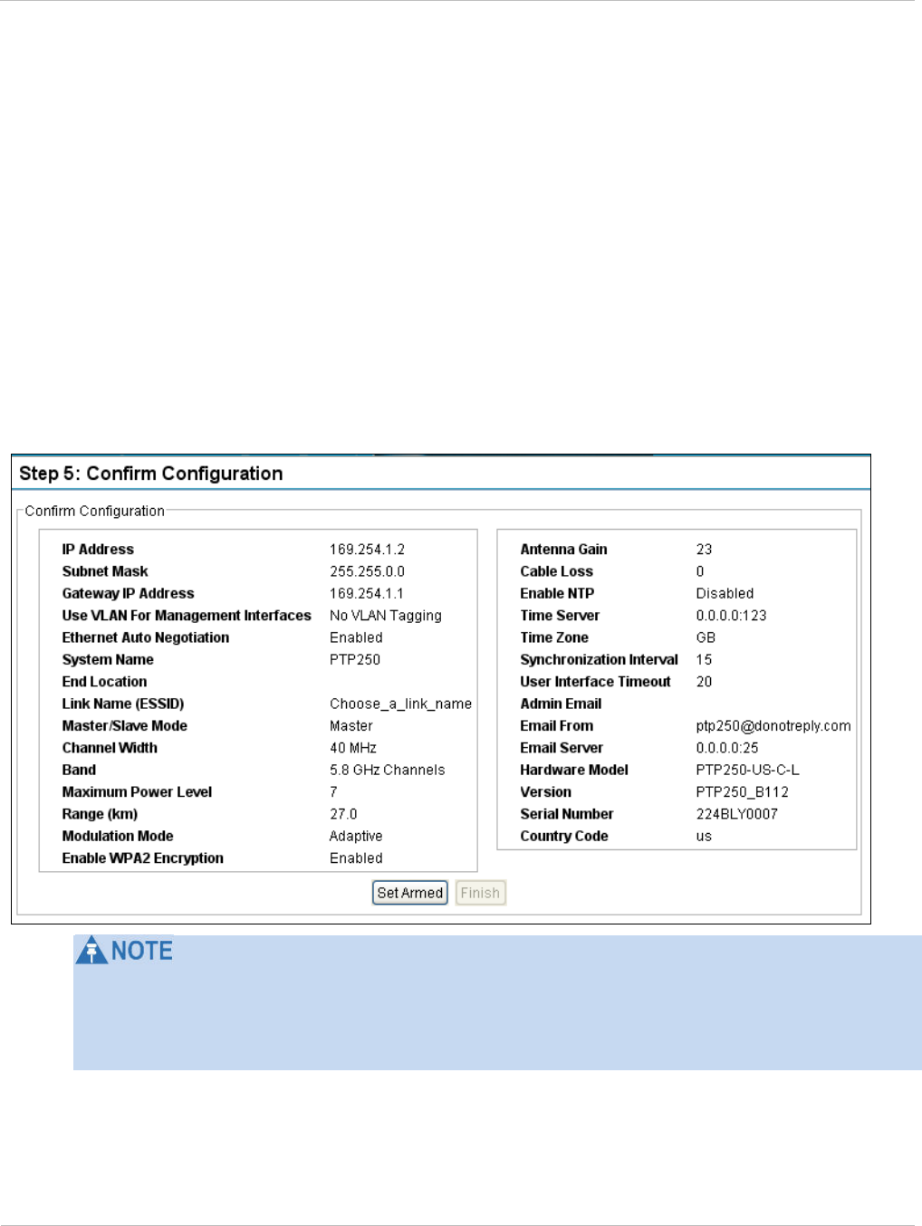
Using the installation wizard Chapter 6: Configuration and alignment
6-22 UNDER DEVELOPMENT phn-2182_003v004 (Oct 2011)
Step 5: Confirm installation configuration
Step 5 of the Installation wizard is for reviewing and confirming the updated attributes
(Figure 6-18).
If any of the attributes are incorrect, select Back to return to previous steps and update
them.
If all attributes are correct, choose one of the following options:
• If antenna alignment tones are not wanted, select Finish. This is the preferred option
before bench testing the units.
• If antenna alignment tones are wanted, select Set Armed and Yes to confirm. This is
the preferred option before site installation and antenna alignment.
Figure 6-18 Step 5: Confirm Configuration page
If the IP Address, Subnet Mask or Gateway IP Address of the unit have been updated to
meet network requirements, then reconfigure the local management PC to use an IP
address that is valid for the network. Refer to Configuring the management PC on page 6-
3.

PTP 250 User Guide Aligning antennas
phn-2182_003v004 (Oct 2011) UNDER DEVELOPMENT 6-23
Aligning antennas
Before performing this task, check that hardware installation is complete (apart from the
network connections) at both the Master and Slave sites.
This task consists of the following procedures:
• Starting up the units on page 6-23
• Checking that the units are armed on page 6-24
• Aligning antennas on page 6-24
• Aligning separate antennas for spatial diversity on page 6-26
• Monitoring received signal level on page 6-26.
• Disarming the units on page 6-29
Starting up the units
To connect one of the units to a management PC and start up both units, proceed as
follows:
1 Select the unit from which this process is to be controlled; either Master or Slave.
This is the ‘local’ unit.
2 Check that the management PC is connected to the local unit, powered up and
logged on.
3 Start the local unit.
4 Start the remote unit.
5 Log into the local unit as described in Logging into the web interface on page 6-6.
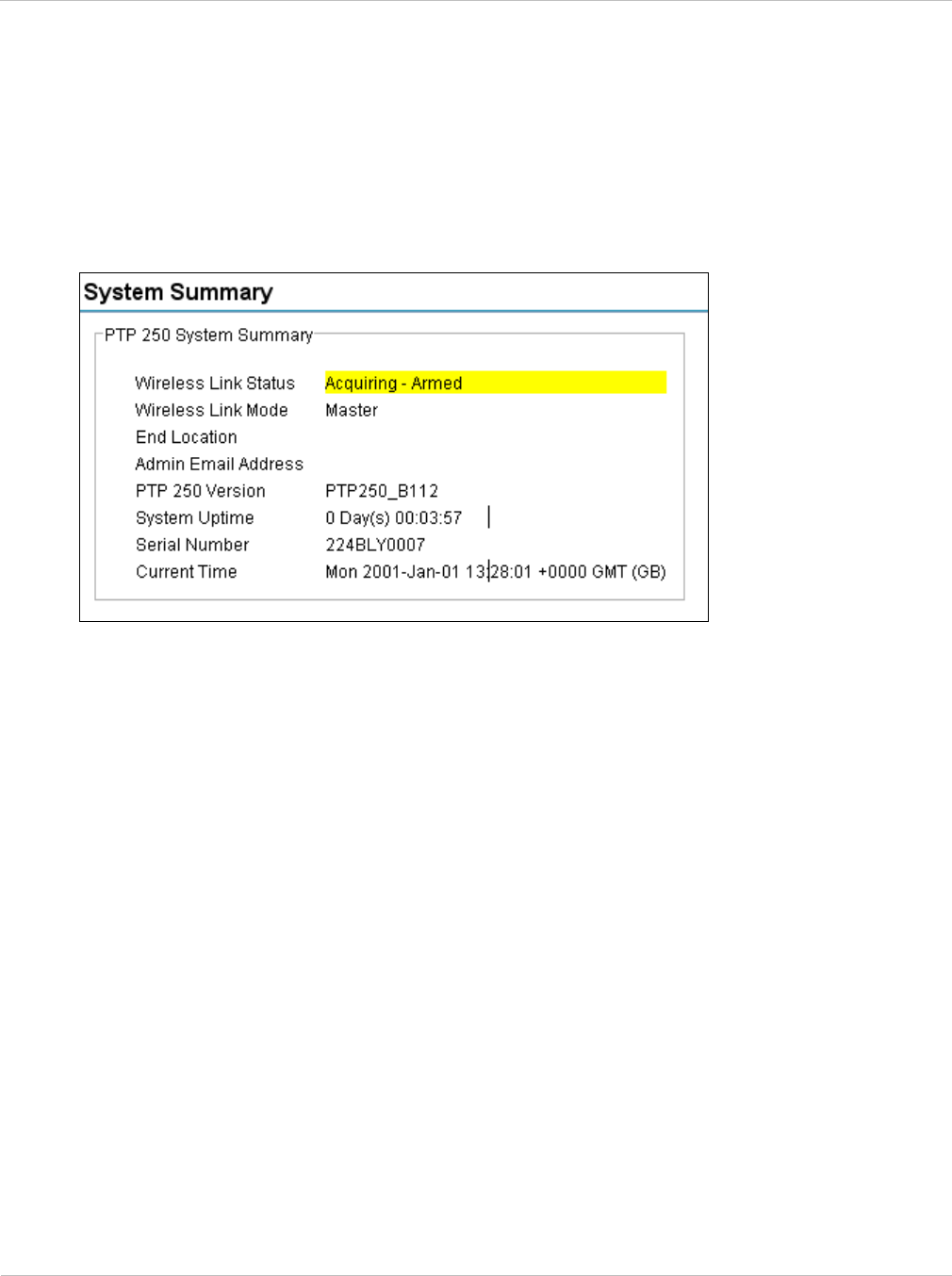
Aligning antennas Chapter 6: Configuration and alignment
6-24 UNDER DEVELOPMENT phn-2182_003v004 (Oct 2011)
Checking that the units are armed
Select menu option Home. The System Summary page is displayed. Check that the
Wireless Link Status contains the word ‘Armed’ (Figure 6-19); this confirms that the units
are ready for alignment.
Figure 6-19 System Summary page (when unit is armed)
If the units are not armed, use the installation wizard (Step 5) to arm them, as described in
Using the installation wizard on page 6-13.
Aligning antennas
Use this procedure to align linked antennas (master and slave), whether integrated or
connectorized.
Prior to alignment, ensure that the following parameters are available:
• Location of both sites (latitude and longitude).
• Bearing to the other end of the link for both sites.
• Prediction of receive signal level for both ends of the link.
• Prediction of link loss.
PTP LINKPlanner provides all of these parameters in the form of an installation report.
If a connectorized ODU is installed at either site with two separate antennas for spatial
diversity, refer to Aligning separate antennas for spatial diversity on page 6-26 before
starting alignment.

PTP 250 User Guide Aligning antennas
phn-2182_003v004 (Oct 2011) UNDER DEVELOPMENT 6-25
To achieve best results, make small incremental changes to elevation and azimuth.
The action of tightening the mounting bolts can alter antenna alignment. This can be
helpful when fine-tuning alignment, but it can also lead to misalignment. To prevent
misalignment, continue to monitor receive signal level during final tightening of the bolts.
To align the antennas, proceed as follows:
1 At each end of the link, adjust the antenna to point at the other end of the link.
This should be done with the aid of a compass.
2 Without moving the master antenna, adjust the elevation and azimuth of the
slave antenna to achieve the highest receive signal level (using one of the
recommended methods in Monitoring received signal level on page 6-26).
3 Without moving the Slave antenna, adjust the elevation and azimuth of the
Master antenna to achieve the highest receive signal level (using one of the
recommended methods).
4 Repeat steps 2 and 3 as necessary to fine-tune the alignment to find the center of
the beam.
5 When the antennas have been aligned on the center of the beam, verify that the
receive level is within the predicted range (from the installation report). If this is
not the case, go back to step 2.
The current value of receive level can be verified by using Graphical alignment
on page 6-28 or by selecting menu option Status and monitoring the Receive
Power attribute on the System Status page.
6 If after repeated attempts to align, the receive level still does not lie within the
predicted range, this may be because the data provided to the prediction tool
(such as PTP LINKPlanner) is inaccurate. For example estimates of path
obstructions, antenna heights or site locations may be inaccurate. Check this
data and update the prediction as necessary.
7 Once the antennas have been aligned correctly, tighten the integrated ODU (or
connectorized antenna) mountings. To ensure that the action of tightening does
not alter antenna alignment, continue to monitor received signal level.

Aligning antennas Chapter 6: Configuration and alignment
6-26 UNDER DEVELOPMENT phn-2182_003v004 (Oct 2011)
Aligning separate antennas for spatial diversity
If a connectorized ODU is installed at either site with two separate antennas for spatial
diversity, proceed as follows:
1 Connect the horizontal polarization antenna to the ODU, disconnect the vertical
polarization antenna, and then perform Aligning antennas on page 6-24.
2 Connect the vertical polarization antenna to the ODU, disconnect the horizontal
polarization antenna, and then perform Aligning antennas on page 6-24.
3 Re-connect the horizontal polarization antennas. The received signal level should
increase.
4 Weatherproof the antenna connections at the ‘H’ and ‘V’ interfaces of the ODUs,
as described in Mounting and connecting antennas on page 5-8.
Monitoring received signal level
The goal of antenna alignment is to find the center of the main beam. This is done by
adjusting the antennas while monitoring the receive signal level. Choose one of two
methods for monitoring receive signal level:
• Antenna alignment tones on page 6-27
• Graphical alignment on page 6-28

PTP 250 User Guide Aligning antennas
phn-2182_003v004 (Oct 2011) UNDER DEVELOPMENT 6-27
Antenna alignment tones
This is the first method that may be used to monitor receive signal level during antenna
alignment.
The ODU emits audible tones during installation to assist with alignment. The pitch of the
alignment tone is proportional to the received power of the wireless signals. Adjust the
alignment of the unit, in both azimuth and elevation, until the highest pitch tone is
achieved.
The tones and their meanings are described in Table 6-5. In each of the states detailed in
the table, align the unit to give the highest pitch tone.
Table 6-5 Antenna alignment tones
State Name Tone
Description State Description Pitch Indication
Free Channel
Search
Regular beep Executing band scan N/A
Scanning Slow broken
tone
Not demodulating the
wanted signal
Rx Power
Synchronized Fast broken tone Demodulating the
wanted signal
Rx Power
Registered Solid tone Both Master and Slave
units exchanging Radio
layer MAC
management messages
Rx Power
Alarm Fast broken dual
tone
A fatal error has
occurred.
The term ‘wanted signal’ refers to that of the peer unit being installed.
If, when in the Synchronized or Registered state, the tone varies wildly, there may be
interference or a fast fading link. Installing in this situation may not give a reliable link.
Investigate the cause of the problem.
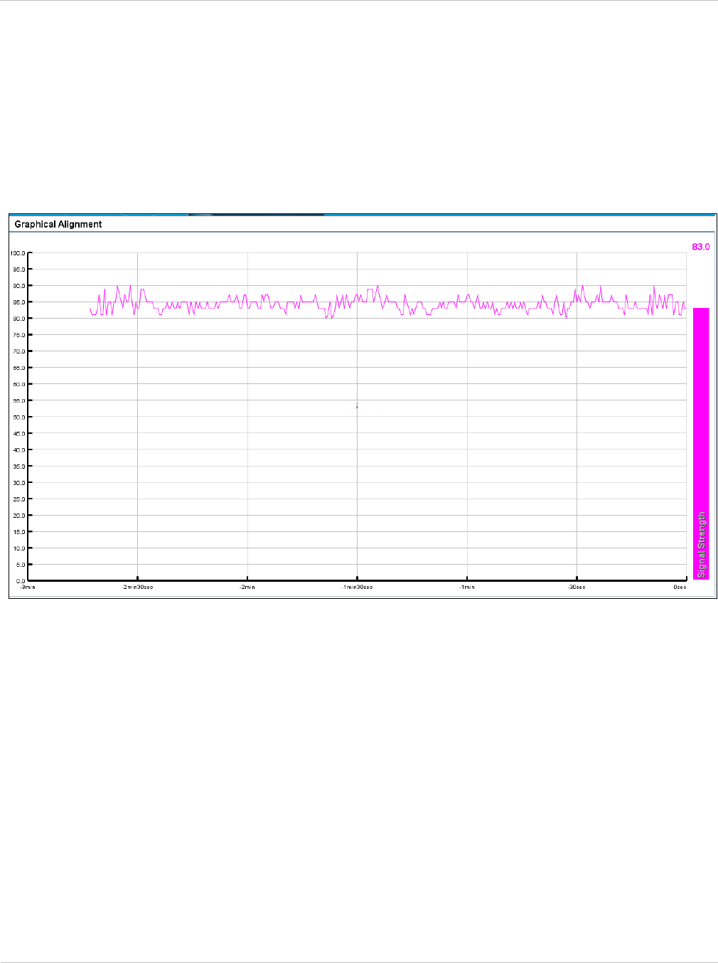
Aligning antennas Chapter 6: Configuration and alignment
6-28 UNDER DEVELOPMENT phn-2182_003v004 (Oct 2011)
Graphical alignment
This is the second method that may be used to monitor receive signal level during antenna
alignment.
Select menu option Installation Wizard, Graphical Alignment. The Graphical
Alignment page is displayed (Figure 6-20).
Figure 6-20 Graphical Alignment page
The Graphical Alignment page displays the receive power over the last three minutes. This
allows the installer to slowly sweep the antenna during installation and monitor the
variation in signal strength with angular position. The page automatically refreshes every
three seconds.
The page displays the instantaneous signal strength at the top right.

PTP 250 User Guide Aligning antennas
phn-2182_003v004 (Oct 2011) UNDER DEVELOPMENT 6-29
Disarming the units
When antenna alignment is complete, both units in the link must be disarmed before
network connection.
To disarm the units, select menu option Installation Wizard. The Step 5: Confirm
Configuration page is displayed (Figure 6-13). Select Set Disarmed, Yes to confirm and
then Back until the Step 1: LAN Configuration page is displayed.

Connecting link to the network Chapter 6: Configuration and alignment
6-30 UNDER DEVELOPMENT phn-2182_003v004 (Oct 2011)
Connecting link to the network
When antenna alignment is complete, the link performance must be checked and then the
link connected to the network for operational running.
This task consists of the following procedures:
• Reviewing system configuration attributes on page 6-30
• Comparing actual to predicted performance on page 6-33
• Connecting to the network on page 6-34
Reviewing system configuration attributes
Review the system configuration to check that it is correct for operational running. To do
this, select the following menu options:
• Configuration (Figure 6-21).
• Configuration, LAN Configuration (Figure 6-22).
• Configuration, Date/Time (Figure 6-23).
If any settings are incorrect, return to the installation wizard and update the configuration
as described in Using the installation wizard on page 6-13.
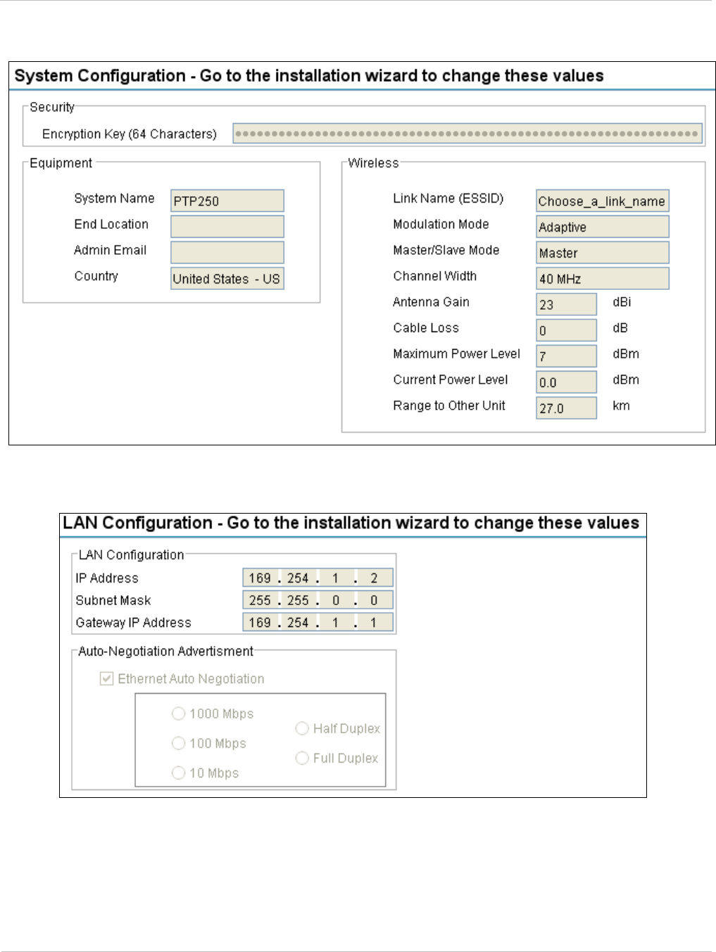
PTP 250 User Guide Connecting link to the network
phn-2182_003v004 (Oct 2011) UNDER DEVELOPMENT 6-31
Figure 6-21 System Configuration page
Figure 6-22 LAN Configuration page
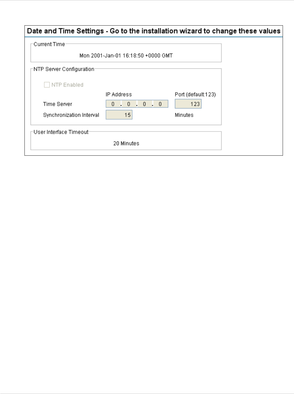
Connecting link to the network Chapter 6: Configuration and alignment
6-32 UNDER DEVELOPMENT phn-2182_003v004 (Oct 2011)
Figure 6-23 Date and Time Settings page
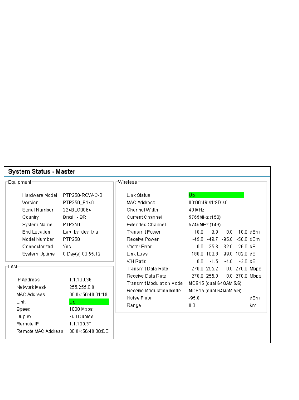
PTP 250 User Guide Connecting link to the network
phn-2182_003v004 (Oct 2011) UNDER DEVELOPMENT 6-33
Comparing actual to predicted performance
For at least one hour of operation after disarming, monitor the link to check that it is
achieving predicted levels of performance.
To check performance, select menu option Status. The System Status page is displayed
(Figure 6-24). Monitor the following attributes:
• Link Loss
• Transmit Data Rate
• Receive Data Rate
For more information on these attributes, refer to Viewing the system status on page 7-8.
PTP LINKPlanner provides the prediction in the form of an installation report.
Figure 6-24 System Status page

Connecting link to the network Chapter 6: Configuration and alignment
6-34 UNDER DEVELOPMENT phn-2182_003v004 (Oct 2011)
Connecting to the network
To connect to the network, proceed as follows:
1 Disconnect the local PC from the PoE power supply at the Master and Slave sites.
2 At each site, connect the PoE power supply DATA IN ports to a router port,
switch port or other network equipment in the data network (Figure 6-3) using
the CAT5e cable that was prepared for this purpose in Preparing the PoE power
supply to network equipment cable on page 5-32.
3 Check that the Master and Slave units are reachable from the network
management system by opening the web interface to the management agents, or
by requesting ICMP echo response packets using the Ping application. The
network management system will normally be geographically remote from the
sites, so it may be necessary to request that this action is completed by co-
workers at the management center.
4 Check the data network for correct operation across the wireless link. This may
be by requesting ICMP echo response packets between hosts in the connected
network segments, or by some more structured use of network testing tools.
5 Select menu option Home or Status and check that the Wireless Link Status is
‘Up’ on both units. If it is not ‘Up’, refer to Managing link status and alerts on
page 7-15.
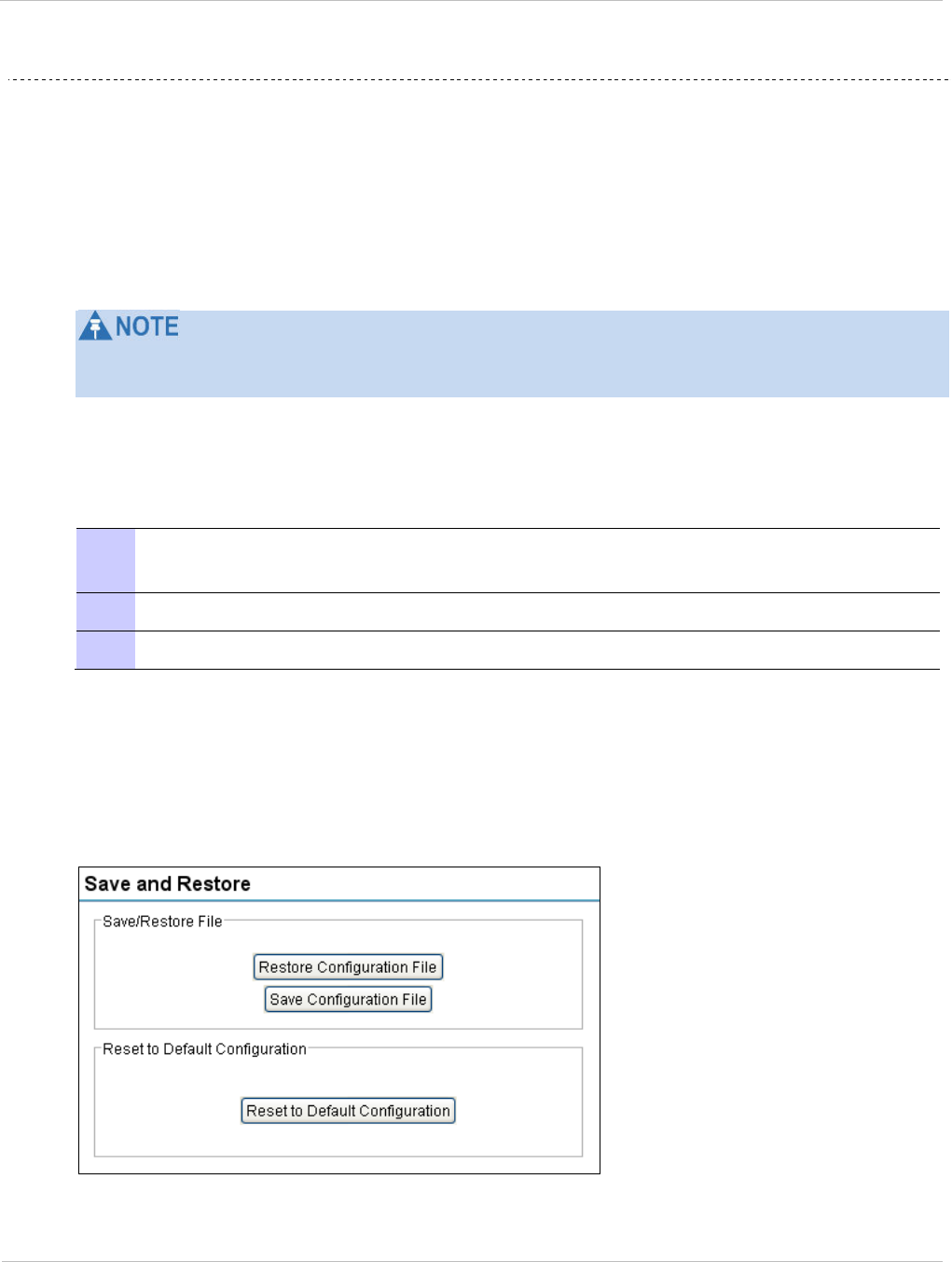
PTP 250 User Guide Saving the system configuration
phn-2182_003v004 (Oct 2011) UNDER DEVELOPMENT 6-35
Saving the system configuration
Save the system configuration in the following situations:
• After a new unit has been fully configured as described in this chapter.
• After any change has been made to the configuration.
• Before upgrading the unit to a new firmware version.
• After upgrading the unit to a new firmware version.
The process for restoring a unit to a previously saved configuration is described in
Restoring the system configuration on page 7-24.
Saving the system configuration
To save the current configuration, proceed as follows:
1 Select menu option System, Configuration, Save And Restore. The Save and
Restore page is displayed (Figure 6-25).
2 Select Save Configuration File.
3 Save the configuration file to a PC hard drive.
The configuration file format is:
mm-mm-mm-mm-mm-mm_iii-iii-iii-iii.cfg
Where: mm-mm-mm-mm-mm-mm Is:
MAC address of unit
iii-iii-iii-iii IP address of unit.
Figure 6-25 Save & Restore page

Saving the system configuration Chapter 6: Configuration and alignment
6-36 UNDER DEVELOPMENT phn-2182_003v004 (Oct 2011)

PTP 250 User Guide
phn-2182_003v004 (Oct 2011) UNDER DEVELOPMENT 7-1
Chapter 7: Operation
This chapter provides instructions for operators of the PTP 250 web user interface.
The following topics are described in this chapter:
• Web-based management on page 7-2 describes the layout and the main menu options
of the PTP 250 web-based management interface.
• Managing link status and alerts on page 7-15 describes how to manage PTP 250 link
status and alerts.
• Managing performance on page 7-17 describes how to manage the performance of the
PTP 250 link.
• Restoring, resetting and rebooting on page 7-24 describes how to restore the system
configuration, reset to defaults, recover the IP address and reboot the unit.

Web-based management Chapter 7: Operation
7-2 UNDER DEVELOPMENT phn-2182_003v004 (Oct 2011)
Web-based management
This section describes the layout and the main menu options of the PTP 250 web-based
management interface. The following topics are covered:
• Accessing the web interface on page 7-2
• Using the menu options on page 7-4
• Viewing the system summary on page 7-6
• Viewing the system status on page 7-8
• Changing password on page 7-14
• Logging out on page 7-14
Accessing the web interface
The web interface is best viewed using a screen resolution of at least 1024 x 768 pixels.
The web pages have been tested with: Internet Explorer 7, Internet Explorer 8, Firefox 3
and Firefox 3.5 on PCs; and Safari on Mac OS X. Other browsers have not been tested.
To access the web interface, type the IP address of the unit into the browser address bar
and press ENTER. When the login page is displayed (Figure 7-1), enter Username ‘admin’
and Password (factory default is ‘motorola’, but this must be changed at first login) and
select Login. The Menu and System Summary are displayed (Figure 7-2).
Figure 7-1 Login page
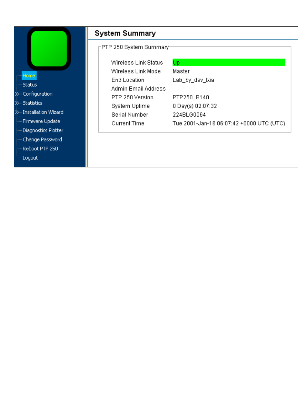
PTP 250 User Guide Web-based management
phn-2182_003v004 (Oct 2011) UNDER DEVELOPMENT 7-3
Figure 7-2 Menu and System Summary page (wireless link up)

Web-based management Chapter 7: Operation
7-4 UNDER DEVELOPMENT phn-2182_003v004 (Oct 2011)
Using the menu options
All web pages contain the menu navigation bar on the left hand side (Figure 7-3). The
menu is used to navigate to other web pages. The currently selected option is always
highlighted with a light blue background.
Figure 7-3 Menu navigation bar
Table 7-1 lists the procedures that may be performed from each menu option. Many of
these procedures are part of the initial configuration and alignment process described in
Chapter 6: Configuration and alignment.

PTP 250 User Guide Web-based management
phn-2182_003v004 (Oct 2011) UNDER DEVELOPMENT 7-5
Table 7-1 Procedures performed from each menu option
Menu option Procedures
Home Viewing the system summary on page 7-6
Managing link status and alerts on page 7-15
Checking that the units are armed on page 6-24
Status Viewing the system status on page 7-8
Checking the installed firmware version on page 6-10
Configuration Reviewing system configuration attributes on page 6-30
LAN Configuration Reviewing system configuration attributes on page 6-30
Recovering a lost IP address on page 7-28
Date/Time Reviewing system configuration attributes on page 6-30
Save and Restore Saving the system configuration on page 6-35
Restoring the system configuration on page 7-24
Resetting to default configuration (without country reset)
on page 7-25
Statistics Checking system statistics on page 7-17
Comparing actual to predicted performance on page 6-33
Test Ethernet packet errors reported by ODU on page 8-8
Channel Status Checking channel status on page 7-19
Retry Histogram Checking the retry histogram on page 7-20
Installation Wizard Using the installation wizard on page 6-13
Graphical Alignment Graphical alignment on page 6-28
Firmware Update Uploading a new firmware version on page 6-11
Diagnostics Plotter Using the diagnostics plotter on page 7-21
Change Password Changing password on page 7-14
Reboot PTP 250 Rebooting the unit on page 7-28
Logout Logging out on page 7-14
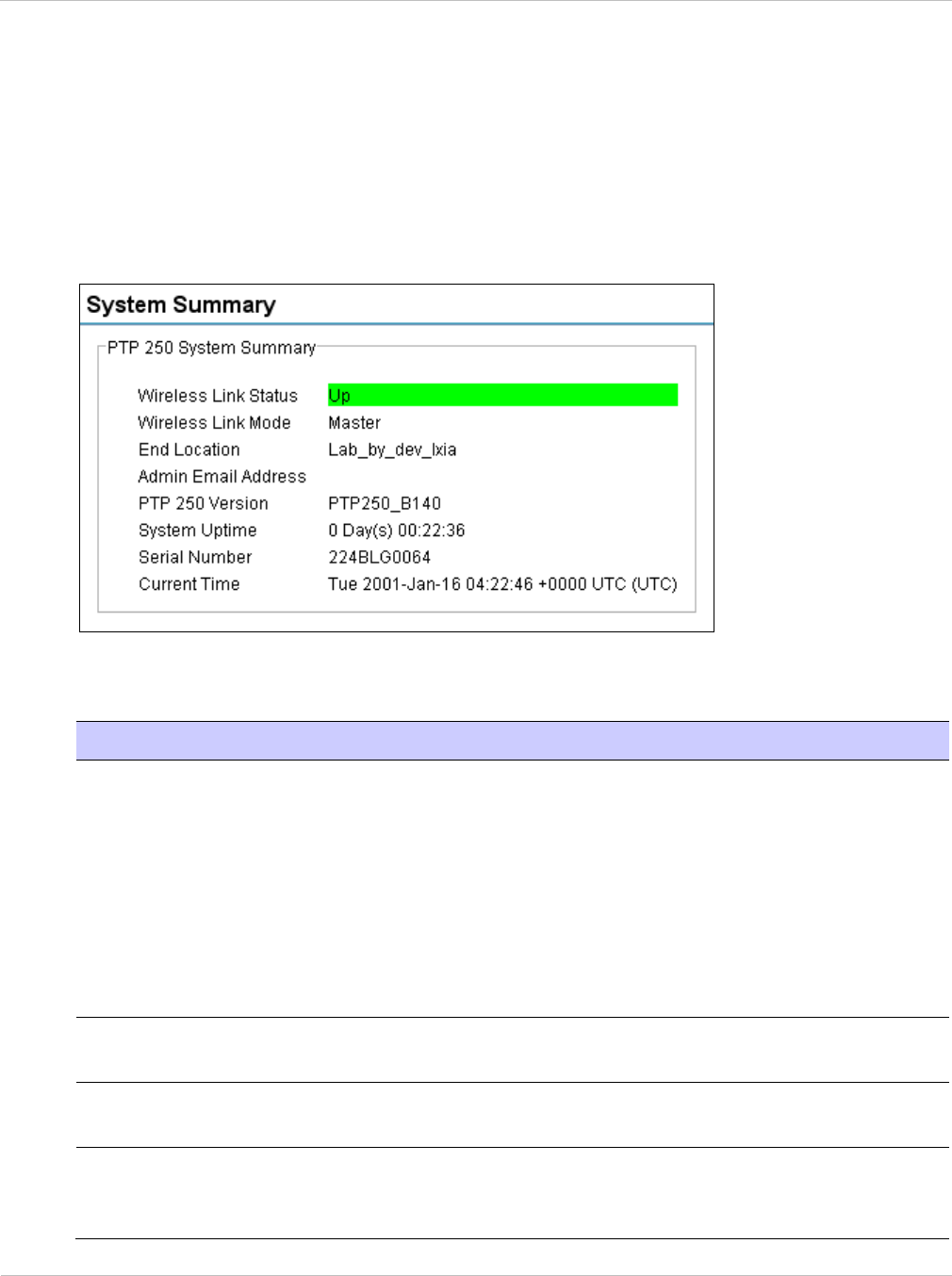
Web-based management Chapter 7: Operation
7-6 UNDER DEVELOPMENT phn-2182_003v004 (Oct 2011)
Viewing the system summary
To display the System Summary page, select menu option Home.
The System Summary page (Figure 7-4) contains a high level summary of the status of the
wireless link and associated equipment.
Figure 7-4 System Summary page
The attributes of the System Summary page are described in Table 7-2.
Table 7-2 System Summary attributes
Attribute Meaning
Wireless Link
Status
Current status of the wireless link.
A green background with status text ‘Up’ means that the point-
to-point link is established.
A yellow background with suitable status text (for example
‘Acquiring’) indicates that the link is not established.
Whenever the Wireless Link Status is not ‘Up’, a yellow warning
triangle is displayed on the navigation bar. For more information,
refer to Managing link status and alerts on page 7-15.
Wireless Link
Mode
Master or Slave. This is set in the Installation Wizard; see Step 2:
Wireless configuration on page 6-16.
End Location Location of this link end. This is set in the Installation Wizard;
see Step 2: Wireless configuration on page 6-16.
Admin Email
Address
The email address configured for email alerts. This is set in the
Installation Wizard; see Step 4: Email configuration on page 6-
21.

PTP 250 User Guide Web-based management
phn-2182_003v004 (Oct 2011) UNDER DEVELOPMENT 7-7
Attribute Meaning
PTP 250 Version The currently running firmware version.
System Uptime The time (days and hh:mm:ss) that has elapsed since the last
system reboot.
The system can reboot for several reasons, for example,
commanded reboot from the Reboot PTP 250 webpage, or a
power cycle of the equipment.
Serial Number Serial number of this unit.
Current Time The system clock presented as local time, allowing for zone and
daylight saving. This is set in the Installation Wizard; see Step 3:
Date and time settings on page 6-18.
Status attributes Status attributes may be displayed in the System Summary page
to indicate abnormal states.
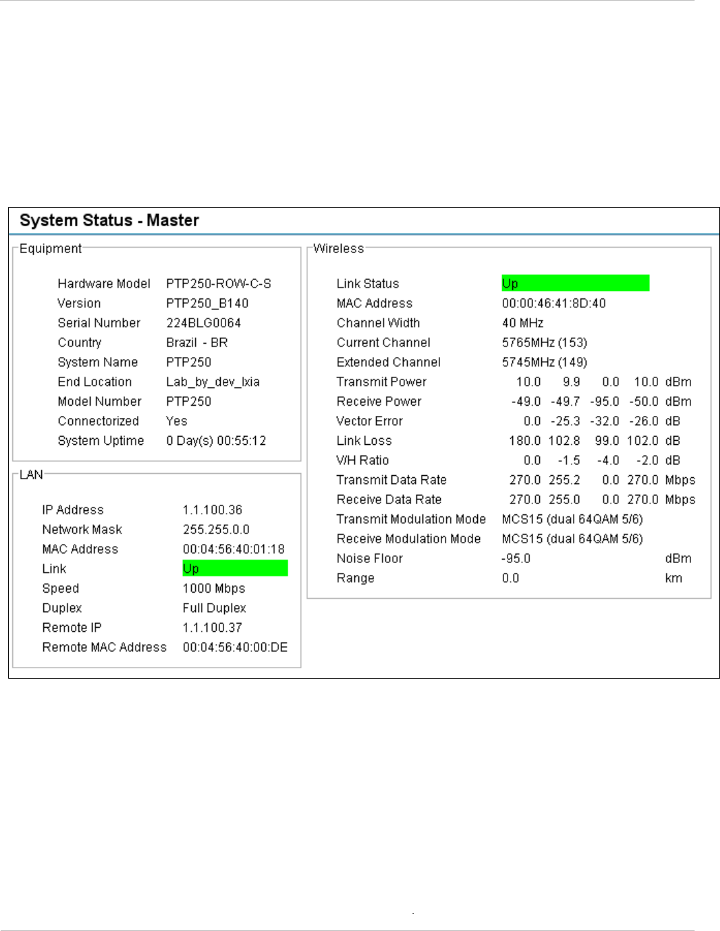
Web-based management Chapter 7: Operation
7-8 UNDER DEVELOPMENT phn-2182_003v004 (Oct 2011)
Viewing the system status
To display the System Status page, select menu option Status.
The System Status page (Figure 7-5) gives the user a detailed view of the operation of the
system from both the wireless and network perspectives.
Figure 7-5 System Status page
The page is subdivided into three sections:
• Equipment: This contains the unit’s inventory and identification information.
• LAN: This describes the unit’s network identity and connectivity.
• Wireless: This presents the key wireless metrics, which are displayed as a series of
measurements.
The two ODUs are arranged in a master and slave relationship. The roles of the units in
this relationship are displayed in the page title. The master unit will always have the title ‘-
Master’, and the slave will always have ‘- Slave’ appended to the ‘Systems Status’ page
title.
The status page attributes are defined in Table 7-3, Table 7-4 and Table 7-5.

PTP 250 User Guide Web-based management
phn-2182_003v004 (Oct 2011) UNDER DEVELOPMENT 7-9
Table 7-3 System Status Equipment attributes
Attribute Meaning
Hardware Model Hardware model of this unit.
Version The version of firmware installed. The format of the attributes is
250-xx-yy
where:
xx
is system release,
yy
minor system release.
Serial Number Serial number of this unit.
Country The country in which this unit is configured to operate. This is set
at first login, as described in Logging into the web interface on
page 6-6. This can only be reset by restoring the unit to factory
default configuration, as described in Resetting to default
configuration (with country reset) on page 7-26.
System Name Name of this PTP 250 system. This is set in the Installation
Wizard; see Step 2: Wireless configuration on page 6-16.
End Location Location of this link end. This is set in the Installation Wizard;
see Step 2: Wireless configuration on page 6-16.
Model Number Model number of this unit.
Connectorized ‘Yes’ means that the unit is connectorized.
‘No’ means that the unit is integrated.
System Uptime The time (days and hh:mm:ss) that has elapsed since the last
system reboot.
The system can reboot for several reasons, for example,
commanded reboot from the Reboot PTP 250 webpage, or a
power cycle of the equipment.

Web-based management Chapter 7: Operation
7-10 UNDER DEVELOPMENT phn-2182_003v004 (Oct 2011)
Table 7-4 System Status LAN attributes
Attribute Meaning
IP Address Internet protocol (IP) address. The factory default is 169.254.1.1,
but it may be reset in the Installation Wizard; see Step 1: LAN
configuration on page 6-14.
Network Mask Defines the address range of the connected IP network. The
factory default is 255.255.0.0, but it may be reset in the
Installation Wizard; see Step 1: LAN configuration on page 6-14.
MAC Address MAC address of the Ethernet LAN port of this unit. This is not
user-configurable.
Link The current status of the Ethernet link. A state of ‘Up’ with a
green background indicates that an Ethernet link is established.
Any status on a yellow background indicates that the Ethernet
link is not established.
Speed The negotiated speed (Mbps) of the Ethernet interface.
Duplex Indicates whether the unit is transmitting data in full duplex or
half duplex mode. Full duplex is expected in normal operation.

PTP 250 User Guide Web-based management
phn-2182_003v004 (Oct 2011) UNDER DEVELOPMENT 7-11
Table 7-5 System Status Wireless attributes
Attribute Meaning
Link Status Current status of the wireless link. A state of ‘Up’ on a green
background indicates that a point-to-point link is established. Any
status on a yellow background indicates that the wireless link is
not established.
Whenever the Link Status is not ‘Up’, a yellow warning triangle is
displayed on the navigation bar. For more information, refer to
Managing link status and alerts on page 7-15.
MAC Address MAC address of the radio interface of this unit.
Channel Width Width of the wireless channel, either 20 MHz or 40 MHz. This is
set in the Installation Wizard; see Step 2: Wireless configuration
on page 6-16.
Current Channel The channel (MHz) in which this link operates. This is set in the
Installation Wizard; see Step 2: Wireless configuration on page 6-
16.
Extended Channel The extended channel (MHz). This only applies when Channel
Width is 40 MHz.
Transmit Power The maximum, mean, minimum and latest measurements of
Transmit Power (dBm). See Diagnostics calculated over time on
page 7-23.
Receive Power The maximum, mean, minimum and latest measurements of
Receive Power (dBm). See Diagnostics calculated over time on
page 7-23.
Vector Error The maximum, mean, minimum and latest measurements of
Vector Error (dB). See Diagnostics calculated over time on page
7-23.
The vector error measurement compares the In-phase /
Quadrature (IQ) modulation characteristics to an ideal signal to
determine the composite error vector magnitude.
Vector Error is expected to range from -2 dB (NLOS link
operating at sensitivity limit on BPSK 0.50) to –27 dB (short LOS
link running 64QAM 0.83). These are approximate values.

Web-based management Chapter 7: Operation
7-12 UNDER DEVELOPMENT phn-2182_003v004 (Oct 2011)
Attribute Meaning
Link Loss The maximum, mean, minimum and latest measurements of Link
Loss (dB). See Diagnostics calculated over time on page 7-23.
The link loss is the total attenuation of the wireless signal
between the two point-to-point units. The link loss calculation
presented below:
xxxx RTRTll ggPPP
+
+
−
=
Where:
ll
P = Link Loss (dB)
x
T
P = Transmit power of the remote wireless unit (dBm)
x
R
P = Received signal power at the local unit (dBm)
xx RT gg , = Antenna gain at the remote and local units
respectively (dBi). The antenna gain of the ODU (23.5 dBi) is
used unless one or both of the units is a Connectorized
version.
For connectorized ODUs, the link loss calculation is modified to
allow for the increased antenna gains at each end of the link.
V/H Ratio The maximum, mean, minimum and latest measurements of V/H
Ratio. See Diagnostics calculated over time on page 7-23.
This is calculated from:
Power received by the vertical antenna input (dB) ÷
Power received by the horizontal antenna input (dB)
V/H Ratio is an aid to debugging a link. If it has a large positive
or negative value, then investigate the following potential
problems:
An antenna coaxial lead may be disconnected.
When spatial diversity is employed, the antenna with the
lower value may be pointing in the wrong direction.
When a dual polar antenna is deployed, the antenna may be
directed using a side lobe rather than the main lobe.
When there is a reflection from water on the link and spatial
diversity is employed, then one expects large, slow swings in V/H
Ratio. This indicates the antenna system is doing exactly as
intended.

PTP 250 User Guide Web-based management
phn-2182_003v004 (Oct 2011) UNDER DEVELOPMENT 7-13
Attribute Meaning
Transmit Data Rate The maximum, mean, minimum and latest measurements of
Transmit Data Rate (Mbps). See Diagnostics calculated over time
on page 7-23.
Receive Data Rate The maximum, mean, minimum and latest measurements of
Receive Data Rate (Mbps). See Diagnostics calculated over time
on page 7-23.
Transmit
Modulation Mode
The modulation mode currently being used on the transmit
channel.
Receive Modulation
Mode
The modulation mode currently being used on the receive
channel.
Noise Floor The noise floor reported by the radio in this unit (dBm).
Range The distance (km) between the two ODUs.
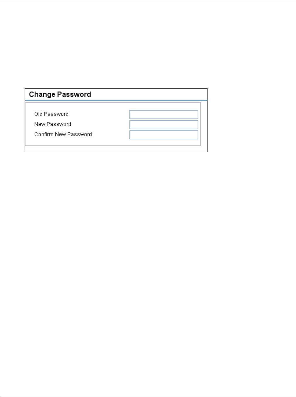
Web-based management Chapter 7: Operation
7-14 UNDER DEVELOPMENT phn-2182_003v004 (Oct 2011)
Changing password
To change the admin password, select menu option Change Password. The Change
Password page is displayed (Figure 7-6). Enter and confirm the new password.
Figure 7-6 Change Password page
Logging out
To maintain security, always log out at the end of a session by selecting menu option
Logout.
Alternatively, the unit will log out automatically, but this depends upon the setting of User
Interface Timeout; see Step 3: Date and time settings on page 6-18.
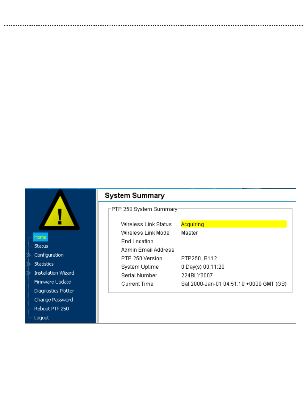
PTP 250 User Guide Managing link status and alerts
phn-2182_003v004 (Oct 2011) UNDER DEVELOPMENT 7-15
Managing link status and alerts
This section describes how to manage PTP 250 link status and alerts.
This section contains the following procedures:
• Managing link status on page 7-15.
• Managing email alerts on page 7-16.
Managing link status
Whenever the Wireless Link Status is not ‘Up’, a yellow warning triangle is displayed on
the navigation bar (Figure 7-7). The warning triangle is visible from all web pages. Click
the warning triangle (or menu option Home) to return to the System Summary page and
view the Wireless Link Status. If the warning triangle is replaced by a green square, it
indicates that the Wireless Link Status is ‘Up’ (Figure 7-2).
The Wireless Link Status values are defined in Table 7-6.
Figure 7-7 Status warning triangle

Managing link status and alerts Chapter 7: Operation
7-16 UNDER DEVELOPMENT phn-2182_003v004 (Oct 2011)
Table 7-6 Wireless Link Status attribute values
Value Meaning
Up The wireless link is up and running.
Registering The wireless link is up, but not yet running (still handshaking,
setting security and so on).
Acquiring The Master unit is waiting for a slave. Only displayed at a Master
unit.
Searching At a Master unit: searching for a quality channel.
At a Slave unit: searching for a Master.
Radar CAC Radar Channel Availability Check (CAC) in progress.
Initializing The unit is starting up or resetting (for example, for a
configuration change or because radar has been detected).
No Channels Radar CAC has determined that there are no useable channels.
Managing email alerts
The management agent can be configured to generate alerts by electronic mail when
certain events occur. The email message configuration procedure is described in Step 4:
Email configuration on page 6-21. The alerts are defined in Table 7-7.
Table 7-7 Email alerts
Alert Meaning
Cold Start The unit has rebooted.
Link Down The link is down.
Link Up The link is up.
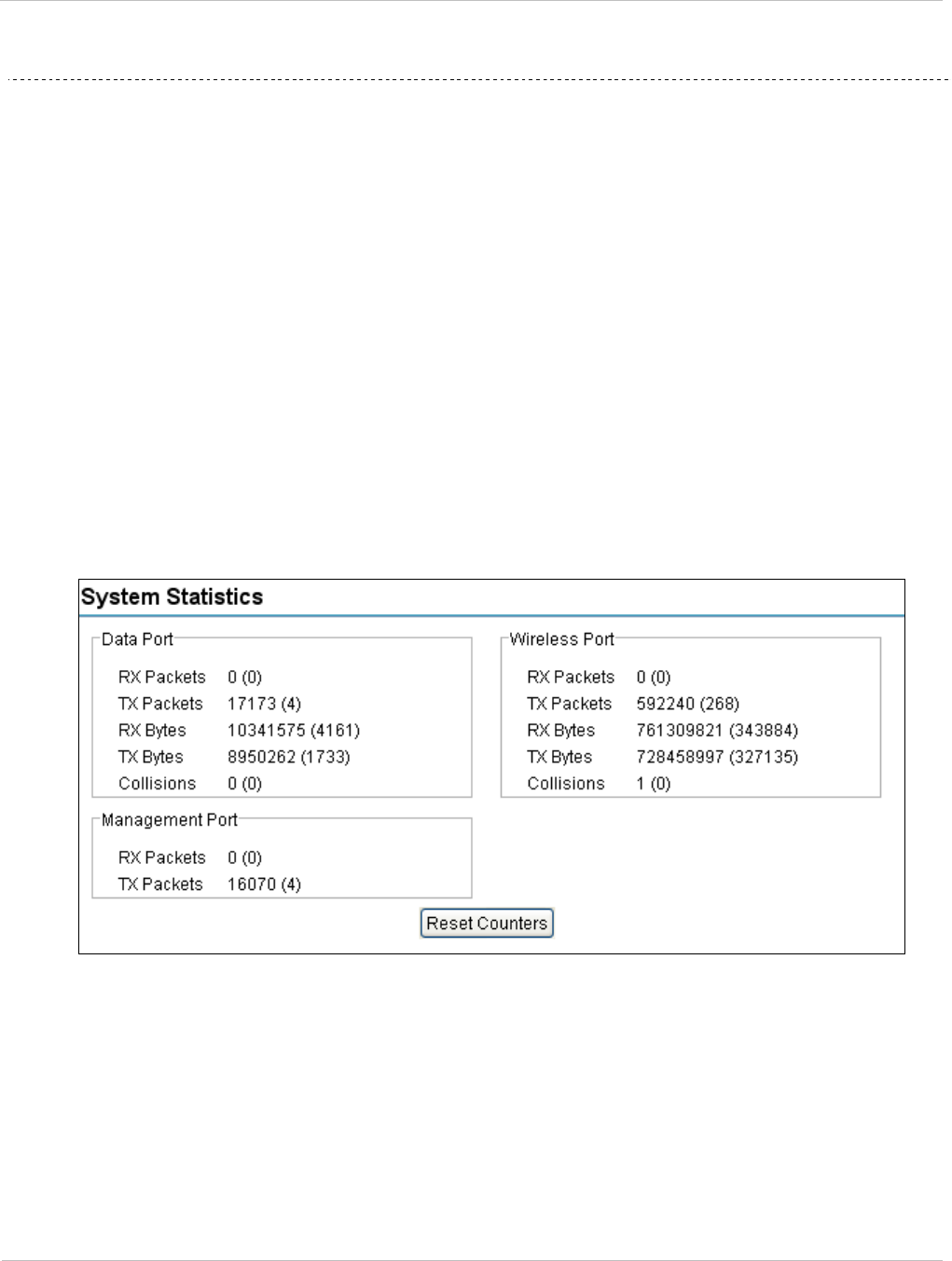
PTP 250 User Guide Managing performance
phn-2182_003v004 (Oct 2011) UNDER DEVELOPMENT 7-17
Managing performance
This section describes how to manage the performance of the PTP 250 link.
This section contains the following procedures:
• Checking system statistics on page 7-17
• Checking channel status on page 7-19
• Checking the retry histogram on page 7-20
• Using the diagnostics plotter on page 7-21
• Diagnostics calculated over time on page 7-23
Checking system statistics
To check system statistics, select menu option Statistics. The System Statistic page is
displayed (Figure 7-8).
Figure 7-8 System Statistics page

Managing performance Chapter 7: Operation
7-18 UNDER DEVELOPMENT phn-2182_003v004 (Oct 2011)
The System Statistics page contains the following system counters:
• Data port counters (Table 7-8)
• Management port counters (Table 7-9)
• Wireless port counters (Table 7-10)
The packet counter attributes each contain a number in parentheses; this shows the
number of packets received since the last page refresh. The page automatically refreshes
every two seconds.
To reset all system counters to zero, select Reset Counters.
Table 7-8 Data Port Counter attributes in the System Statistics page
Attribute Meaning
Rx Packets The number of good and bad packets received from the local
Ethernet interface.
Tx Packets The number of good packets the bridge has sent for transmission
by the local Ethernet interface.
Rx Bytes The number of bytes received by the Ethernet interface.
Tx Bytes The number of bytes transmitted by the Ethernet interface.
Collisions The number of frames experiencing collisions in the local
Ethernet interface.
Table 7-9 Management Port Counter attributes in the System Statistics page
Attribute Meaning
Rx Packets The total number of good packets the bridge has received from
the internal stack (for example ARP responses, PING replies,
HTTP responses).
Tx Packets The total number of good packets the bridge has transmitted to
the internal stack (for example, ARP requests, PING requests,
HTTP requests).
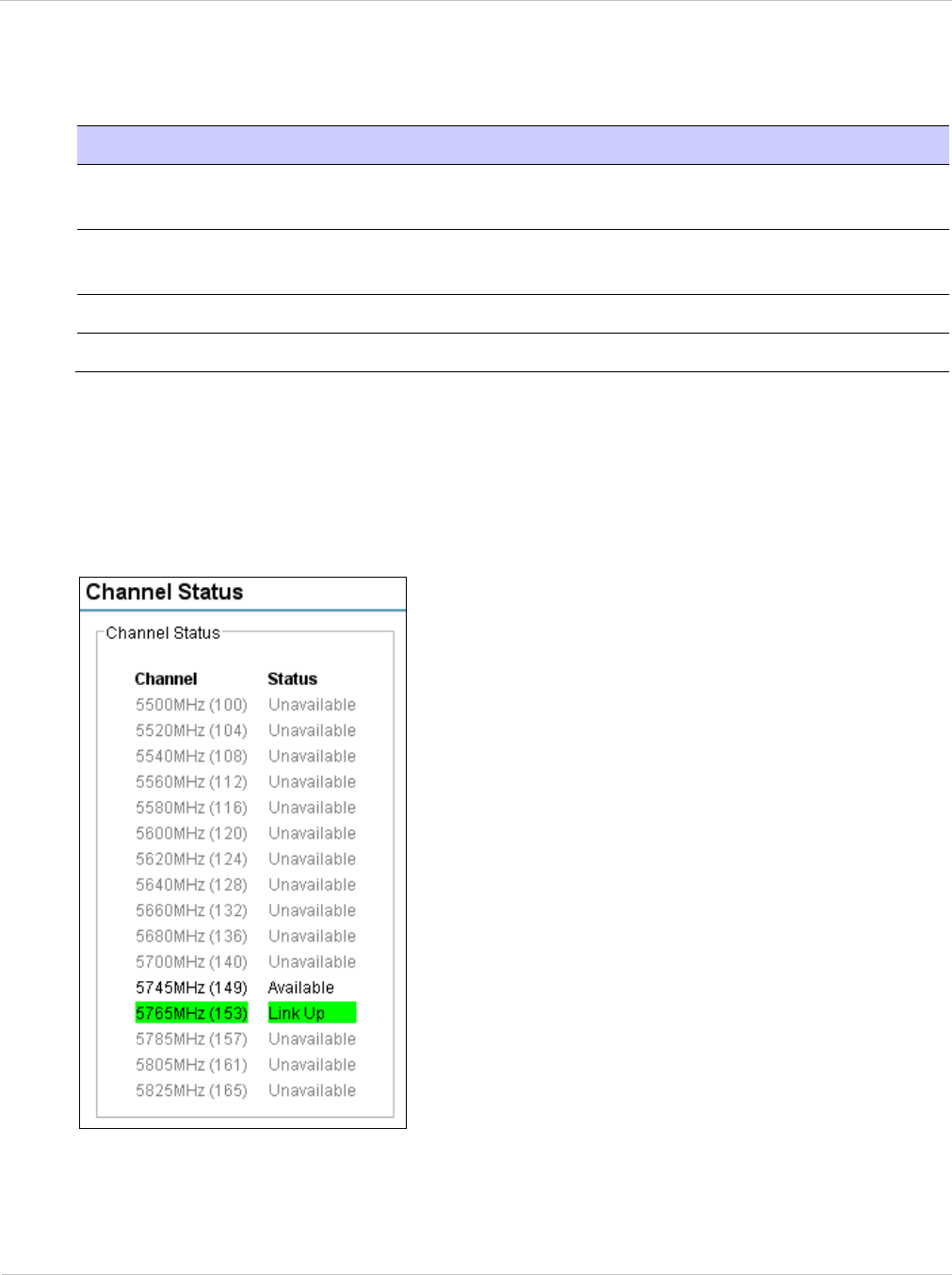
PTP 250 User Guide Managing performance
phn-2182_003v004 (Oct 2011) UNDER DEVELOPMENT 7-19
Table 7-10 Wireless Port Counter attributes in the System Statistics page
Attribute Meaning
Rx Packets The number of good packets the bridge has received from the
wireless interface.
Tx Packets The number of good packets the bridge has sent for transmission
by the wireless interface.
Rx Bytes The number of bytes received from the wireless interface.
Tx Bytes The number of bytes transmitted by the wireless interface.
Checking channel status
To check channel status, select menu option Statistics, Channel Status. The Channel
Status page is displayed (Figure 7-9).
Figure 7-9 Channel Status page

Managing performance Chapter 7: Operation
7-20 UNDER DEVELOPMENT phn-2182_003v004 (Oct 2011)
Checking the retry histogram
The retry histogram gives an indication of wireless quality. It records how many frames
have been re-transmitted how many times. Valid values can vary; a short range LOS link
should run with very few retries. A longer range nLOS link may run with up to 10% retries.
To check the retry histogram, select menu option Statistics, Retry Histogram. The Retry
Histogram page is displayed (Figure 7-10).
Figure 7-10 Retry Histogram page
To reset all retry statistics, select Reset Histogram Statistics.
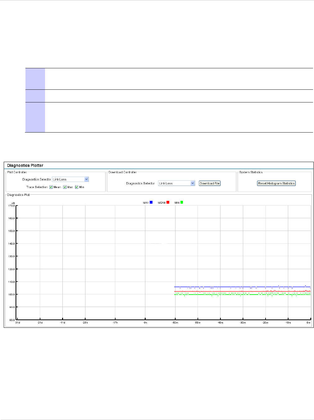
PTP 250 User Guide Managing performance
phn-2182_003v004 (Oct 2011) UNDER DEVELOPMENT 7-21
Using the diagnostics plotter
The Diagnostics Plotter page is used to plot key performance statistics against time.
To plot diagnostics, proceed as follows:
1 Select menu option Diagnostics Plotter. The Diagnostics Plotter page is
displayed (Figure 7-11).
2 Use the Diagnostics Selector drop-down list to select a diagnostic type to plot.
3 Use the Trace Selection to select traces of the maximum, mean or minimum
values of the diagnostic type. Maximum values are displayed in blue, mean
values are displayed in red and minimum values are displayed in green.
Figure 7-11 Diagnostic Plotter page

Managing performance Chapter 7: Operation
7-22 UNDER DEVELOPMENT phn-2182_003v004 (Oct 2011)
Table 7-11 Diagnostics Plotter attributes
Attribute Meaning
Link Loss Defined in Table 7-5.
Transmit Power Defined in Table 7-5.
Receive Power Defined in Table 7-5.
Receive Vector Error Defined in Table 7-5.
Transmit Data Rate Defined in Table 7-5.
Receive Data Rate Defined in Table 7-5.
Aggregated Data Rate The sum of the transmit and receive data rates (Mbps).
V/H Ratio Defined in Table 7-5.
The maximum, mean, minimum and latest values of some of these statistics are also
displayed on the System Status page. See Diagnostics calculated over time on page 7-23.
Downloading diagnostic data
To download a statistic to a CSV file, use the Download Controller. Select the statistic from
the list and select Download File.
The CSV file contains at most 5784 entries, recorded over a 32 day period:
• 3600 entries recorded in the last hour.
• 1440 entries recorded in the previous 24 hours.
• 744 entries recorded in the previous 31 days.
Resetting statistics
To reset all the statistics that are available in the Diagnostics Plotter page, select Reset
Histogram Statistics.
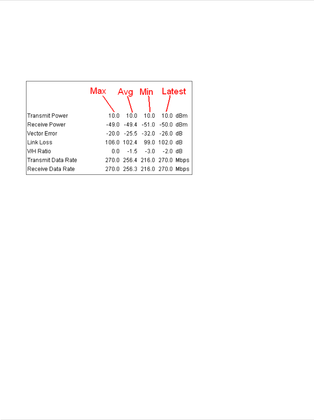
PTP 250 User Guide Managing performance
phn-2182_003v004 (Oct 2011) UNDER DEVELOPMENT 7-23
Diagnostics calculated over time
The System Status page (Figure 7-5) contains seven diagnostic attributes that are
calculated over time and presented as arrays of four elements (Figure 7-12).
Figure 7-12 Diagnostic attributes calculated over time
These attributes are defined in Table 7-5.
The element arrays represent the following:
• Max: The maximum value measured over the last hour.
• Avg: The mean of a set of values recorded at one second intervals over the last hour.
• Min: The minimum value measured the last hour.
• Latest: The latest value measured.
If the link has been running for less than one hour, then the values are calculated over the
time that has elapsed since the link was established.
These attributes can be plotted against time, downloaded and reset by using the
Diagnostics Plotter page, as described in Using the diagnostics plotter on page 7-21.

Restoring, resetting and rebooting Chapter 7: Operation
7-24 UNDER DEVELOPMENT phn-2182_003v004 (Oct 2011)
Restoring, resetting and rebooting
This section describes how to restore the system configuration, reset to defaults, recover
the IP address and reboot the unit.
This section contains the following procedures:
• Restoring the system configuration on page 7-24
• Resetting to default configuration (without country reset) on page 7-25
• Resetting to default configuration (with country reset) on page 7-26
• Recovering a lost IP address on page 7-28
• Rebooting the unit on page 7-28
Restoring the system configuration
Perform this procedure to restore a unit to a previously saved configuration. Refer to
Saving the system configuration on page 6-35 for instructions on when and how to save the
configuration.
The restore is only guaranteed to work if the installed firmware version has not been
changed since the configuration file was saved. This is why the configuration should
always be saved immediately after upgrading the firmware version.
To restore the system configuration from file, proceed as follows:
1 Select menu option Configuration, Save And Restore. The Save & Restore
Configuration page is displayed (Figure 6-25).
2 Select Browse and navigate to the PC folder containing the saved configuration
file (.cfg). Select Open.
4 Select OK to confirm the restore. The configuration file is uploaded and used to
reconfigure the unit to its previous state.

PTP 250 User Guide Restoring, resetting and rebooting
phn-2182_003v004 (Oct 2011) UNDER DEVELOPMENT 7-25
Resetting to default configuration (without country reset)
Use the Save & Restore page to reset the unit to factory default configuration, without
resetting the country of operation (selected at first login).
When the unit is reset to default configuration, the current configuration is lost and the
unit reboots, causing loss of service.
To reset the unit to factory default configuration, including reset of the country that was
selected at first login, follow the procedure in Resetting to default configuration (with
country reset) on page 7-26.
To reset to default configuration without country reset, proceed as follows:
1 Select menu option Configuration, Save And Restore. The Save & Restore
page is displayed (Figure 6-25).
2 Select Reset to Default Configuration and Yes to confirm.
3 Wait for at least 45 seconds.
4 The unit should now be reset to partial factory default settings, including the
following:
Password ‘motorola’,
IP address ‘169.254.1.1’,
Master Slave Status ‘Slave’.
The Country Code (selected at first login) remains unchanged.
5 To reconfigure the unit, follow the instructions in Connecting to the unit on page
6-3 and Using the installation wizard on page 6-13.
When logging into the unit, change Password (this will be prompted).

Restoring, resetting and rebooting Chapter 7: Operation
7-26 UNDER DEVELOPMENT phn-2182_003v004 (Oct 2011)
Resetting to default configuration (with country reset)
Use the reset plug (supplied in each PTP 250 ‘Link Complete’ or ‘End Complete’ kit) to
reset the unit to factory default configuration, including reset of the country of operation
(this will have to be reselected at first login after the reset).
When the unit is reset to default configuration, the current configuration is lost and the
unit reboots, causing loss of service.
To reset the unit to factory defaults without resetting the country of operation, follow the
procedure in Resetting to default configuration (without country reset) on page 7-25.
To reset to default configuration including country reset, proceed as follows:
1 Remove the ODU drop cable from the PoE power supply DATA & POWER OUT
port.
2 Plug the ODU drop cable into the reset plug and then plug the reset plug into the
PoE power supply DATA & POWER OUT port (Figure 7-13).
3 Wait for at least 45 seconds.
4 Disconnect the reset plug and re-insert the ODU drop cable into the PoE power
supply DATA & POWER OUT port.
5 The unit should now be reset to factory default settings, including the following:
Password ‘motorola’,
IP address ‘169.254.1.1’,
Master Slave Status ‘Slave’,
Country Code is blank.
6 To reconfigure the unit, follow the instructions in Connecting to the unit on page
6-3 and Using the installation wizard on page 6-13.
When logging into the unit, change Password and select Country Code (these will
be prompted).
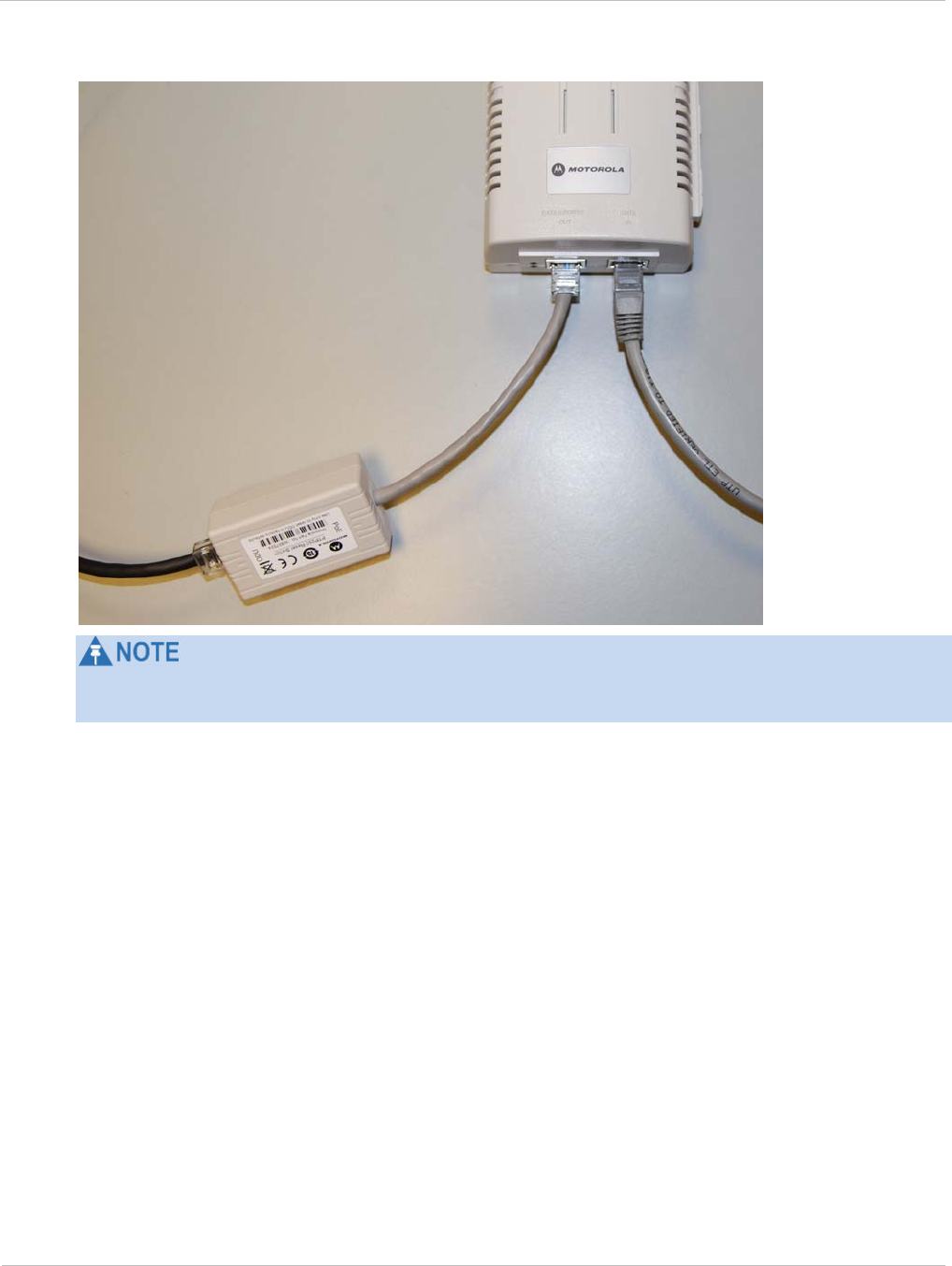
PTP 250 User Guide Restoring, resetting and rebooting
phn-2182_003v004 (Oct 2011) UNDER DEVELOPMENT 7-27
Figure 7-13 Using the reset plug
If the power supply is a PIDU, the PIDU reset switch WILL NOT work. The PTP 250 reset
plug must be used.
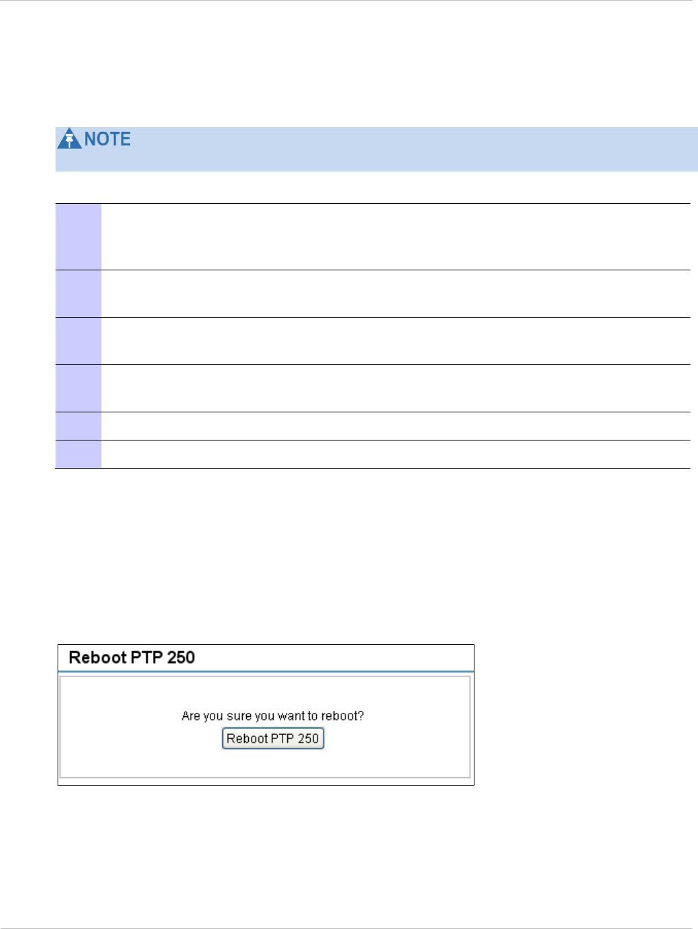
Restoring, resetting and rebooting Chapter 7: Operation
7-28 UNDER DEVELOPMENT phn-2182_003v004 (Oct 2011)
Recovering a lost IP address
To recover a lost IP address, physical access to the PoE power supply is recommended.
The unit does still respond to its normal IP address through a power cycle.
If the IP address of the unit has been lost or forgotten, proceed as follows:
1 Set the management PC Ethernet port to an IP address that is valid for the
169.254.X.X network, avoiding 169.254.0.0, 169.254.1.1 and 169.254.1.2. Refer
to Configuring the management PC on page 6-3.
2 Connect the management PC Ethernet port to the DATA IN port of the PoE
power supply using a standard (not crossed) Cat5e cable (Figure 6-3).
3 Perform a power cycle, that is, disconnect and then reconnect the PoE power
supply to its AC supply.
4 Access the web interface within 30 seconds of powering on, using default IP
address 169.254.1.1.
5 Select menu option Configuration, LAN Configuration.
6 Obtain the correct IP address of the unit from the LAN Configuration page.
Rebooting the unit
To reboot the ODU select menu option Reboot PTP 250. The Reboot Wireless Unit page is
displayed (Figure 7-14). Select Reboot PTP 250 to confirm.
Figure 7-14 Reboot Wireless Unit page

PTP 250 User Guide
phn-2182_003v004 (Oct 2011) UNDER DEVELOPMENT 8-1
Chapter 8: Troubleshooting
This chapter contains procedures for identifying and correcting faults in a PTP 250 link.
These procedures can be performed either on a newly installed link, or on an operational
link if communication is lost, or after a lightning strike.
The following topics are described in this chapter:
• Testing link end hardware on page 8-2 describes how to test the link end hardware,
either when it fails on startup, or after a lightning strike.
• Testing the radio link on page 8-12 describes how to test the link when there is no
radio communication, or when it is unreliable, or when the data throughput rate is too
low

Testing link end hardware Chapter 8: Troubleshooting
8-2 UNDER DEVELOPMENT phn-2182_003v004 (Oct 2011)
Testing link end hardware
This section describes how to test the link end hardware, either when it fails on startup, or
after a lightning strike.
Before testing link end hardware, confirm that all outdoor drop cables, that is those that
connect the ODU to equipment inside the building, are of the supported type, as defined in
Ordering components on page 2-24.
These tests apply to installations that use the PoE power supply. If the PIDU is installed
instead of the PoE power supply, the test procedures will be different.
Testing when PoE LEDs do not illuminate correctly
If the DATA & POWER OUT and DATA IN LEDs do not illuminate correctly during the
start-up sequence, test the link end as described in Test flowcharts on page 8-3 and the
detailed test procedures that follow.
Testing after a lightning strike
If the installation has been struck by lightning, proceed as follows:
1 Test the link end as described in Test flowcharts on page 8-3 and the detailed
test procedures that follow.
2 Ensure that the PoE power supply is working and that the resistances are
correct as specified in Test resistance in the ODU cable on page 8-10.
3 If the ODU is not working, power off the ODU and LPU and return them to
Motorola.
4 If the ODU is working but there is suspicion of damage to the LPU, then refer to
LPU Operational Troubleshooting (phn-1362)
.

PTP 250 User Guide Testing link end hardware
phn-2182_003v004 (Oct 2011) UNDER DEVELOPMENT 8-3
Test flowcharts
Figure 8-1 Link end hardware test flowchart #1
No
Start
Is the PORT LED on
solidl?
Is the AC LED on solid?
Yes
Yes
Is the AC LED flashing? Perform
“AC LED is off”
No
Perform
“AC LED is flashing”
Yes
Is the PORT LED
flashing?
Perform
“PORT LED is off”
No
Perform
“PORT LED is flashing”
Yes
No
Go to next flowchart
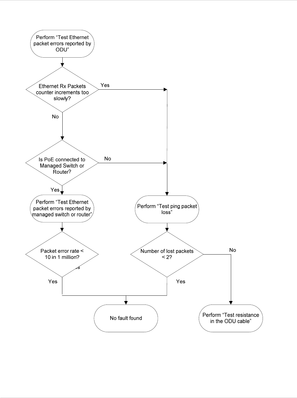
Testing link end hardware Chapter 8: Troubleshooting
8-4 UNDER DEVELOPMENT phn-2182_003v004 (Oct 2011)
Figure 8-2 Link end hardware test flowchart #2

PTP 250 User Guide Testing link end hardware
phn-2182_003v004 (Oct 2011) UNDER DEVELOPMENT 8-5
AC LED is off
If the AC LED is not on solid or flashing, proceed as follows:
1 Remove the power lead from the PoE power supply.
2 Test that the mains power supply is working.
3 If the mains power supply is not working, investigate the cause.
4 If the mains power supply is working, report a suspected PoE power supply fault
to Motorola.
AC LED is flashing
If the green AC LED is flashing, proceed as follows:
1 Test that the voltage from the AC outlet that is within the correct range (100 –
240 V AC). If it is out of this range, investigate and correct the AC supply.
Otherwise, proceed to step 2.
2 Remove and examine the cable that connects the PoE power supply to the LPU
or ODU.
3 Check that the resistances are correct as specified in Test resistance in the ODU
cable on page 8-10.
4 If either check fails, replace or repair the cable that connects the PoE power
supply to the LPU or ODU.

Testing link end hardware Chapter 8: Troubleshooting
8-6 UNDER DEVELOPMENT phn-2182_003v004 (Oct 2011)
PORT LED is off
When the PoE power supply is connected to the power supply and the AC LED illuminates,
there should be a 45 second delay, following which the PORT LED should illuminate (green
steady).
If the PORT LED is off, proceed as follows:
1 Check that the RJ45 connection from the DATA IN port of the PoE power supply
to the PC is working.
2 If the PC connection is working, remove and examine the cable that connects
the PoE power supply to the LPU or ODU.
3 Check that the resistances are correct as specified in Test resistance in the ODU
cable on page 8-10.
4 If this test fails, replace or repair the cable that connects the PoE power supply
to the LPU or ODU.
PORT LED is flashing
If the PORT LED is flashing, proceed as follows:
1 Remove and examine the ODU cable from the PoE power supply.
2 Check that the resistances are correct as specified in Test resistance in the ODU
cable on page 8-10.
3 Use the LPU (if installed) to check that power is available on the cable to the
ODU. Access the connections by rotating the LPU lid as shown in Figure 8-3.
Slacken the lid nut but do not remove it.
4 Test that test point P1 on the LPU PCB corresponds to pin 1 on the RJ45. Repeat
for points P2 to P8.
This test is only valid if both the PoE power supply and the ODU are
disconnected.
5 Check that the PWR LED near the top right of the LPU PCB is illuminated to
indicate power in the Ethernet cable (Figure 8-3).
6 If any test fails, replace or repair the cable that connects the PoE power supply
to the LPU or ODU.

PTP 250 User Guide Testing link end hardware
phn-2182_003v004 (Oct 2011) UNDER DEVELOPMENT 8-7
Figure 8-3 PTP LPU test points and PWR LED

Testing link end hardware Chapter 8: Troubleshooting
8-8 UNDER DEVELOPMENT phn-2182_003v004 (Oct 2011)
Test Ethernet packet errors reported by ODU
To test for Ethernet packet errors, proceed as follows:
1 Log in to the unit and select menu option Statistics.
2 Select Reset Counters at the bottom of the page and wait until the Data Port Rx
Packets counter has reached 1 million.
3 If the counter does not increment or increments too slowly, because for example
the link is newly installed and there is no offered Ethernet traffic, then abandon
this procedure and consider using the procedure Test ping packet loss on page 8-
9.
Test Ethernet packet errors reported by managed switch or
router
If the ODU is connected to a managed Ethernet switch or router, it may be possible to
monitor the error rate of Ethernet packets. Please refer to the user guide of the managed
network equipment.
The test has passed if the rate of packet errors reported by the managed Ethernet switch
or router is less than 10 in 1 million packets.

PTP 250 User Guide Testing link end hardware
phn-2182_003v004 (Oct 2011) UNDER DEVELOPMENT 8-9
Test ping packet loss
Using a computer, it is possible to generate and monitor packets lost between the PoE
power supply and the ODU. This can be achieved by executing the Command Prompt
application which is supplied as standard with Windows and Max OS X operating systems.
To test ping packet loss, proceed as follows:
1 Ensure that the IP address of the computer is configured appropriately for
connection to the ODU under test, and does not clash with the IP addresses of
other devices connected to the network.
2 If the PoE power supply is connected to an Ethernet switch or router then
connect the computer to a spare port, if available.
3 If it is not possible to connect the computer to a spare port of an Ethernet switch
or router, then the PoE power supply will need to be disconnected from the
network in order to execute this test.
The following steps will disrupt network traffic carried by the ODU under test:
Disconnect the PoE power supply from the network.
Connect the computer directly to the LAN port of the PoE power supply.
4 On the computer, open the Command Prompt application.
5 Send 1000 ping packets of length 1500 bytes. The process will take 1000 seconds,
which is approximately 17 minutes.
If the computer is running a Windows operating system, this is achieved by
typing:
ping –n 1000 –l 1500 <ipaddress>
where <ipaddress> is the IP address of the ODU under test.
If the computer is running a MAC operating system, this is achieved by typing:
ping –c 1000 –s 1492 <ipaddress>
where <ipaddress> is the IP address of the ODU under test.
6 Record how many Ping packets have been lost. This is reported by Command
Prompt on completion of the test.
The test has passed if the number of lost packets is less than 2.
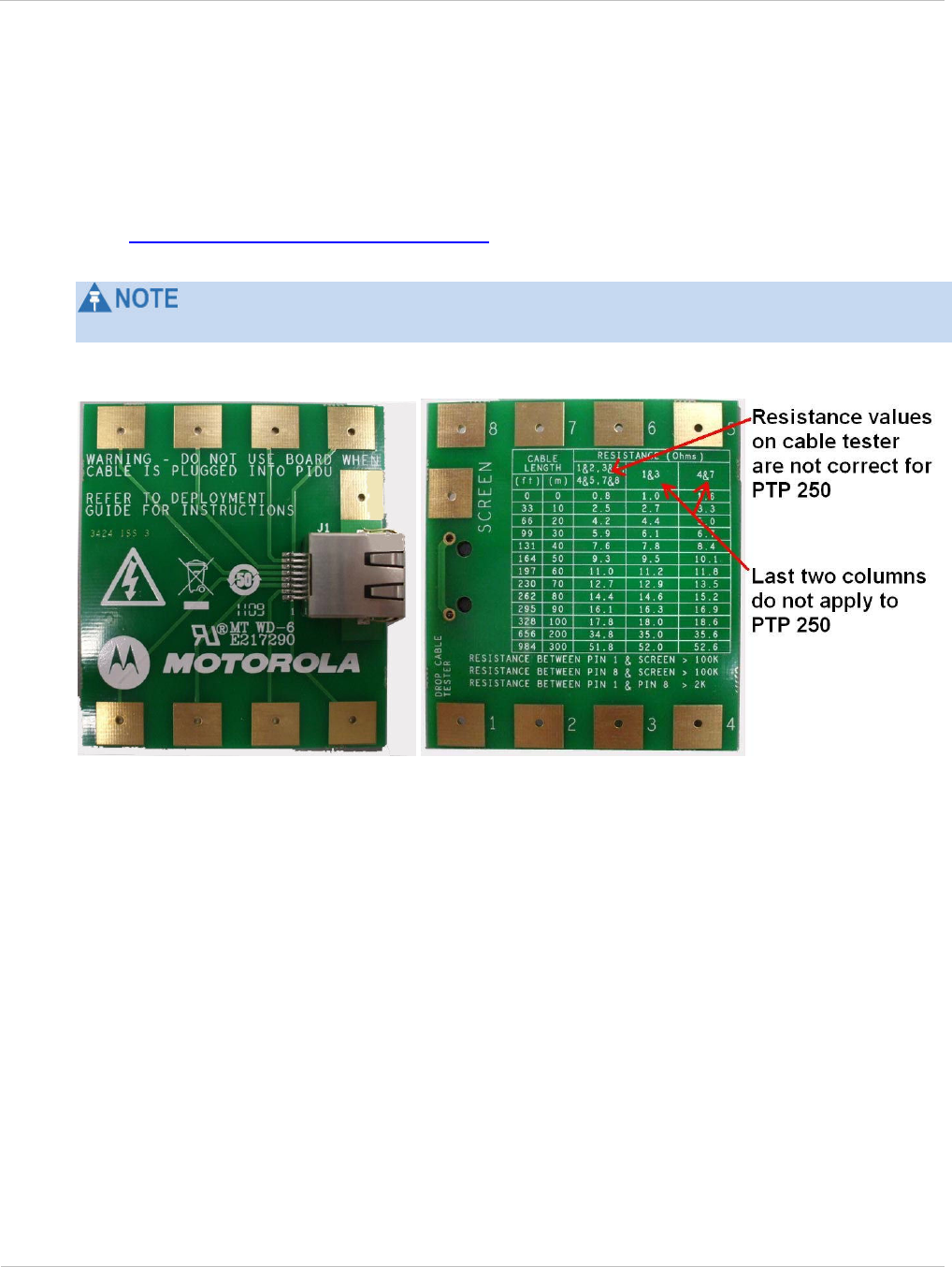
Testing link end hardware Chapter 8: Troubleshooting
8-10 UNDER DEVELOPMENT phn-2182_003v004 (Oct 2011)
Test resistance in the ODU cable
If the above procedures fail to diagnose the issue, there may be a fault in the wiring of the
drop cable that connects the ODU (or LPU) to the PoE. Perform this task to test the
resistances between the RJ45 pins at the PoE end of the ODU cable.
Use the PTP drop cable tester (Figure 8-4) to make testing easier. This can be ordered
from http://www.motorola.com/ptp/support by selecting Order Cable Tester and
completing the order form.
The values printed on the PTP drop cable tester do not apply to the PTP 250.
Figure 8-4 Drop cable tester (front and back views)
Unplug the drop cable from the DATA & POWER OUT port of the PoE power supply.
Connect the drop cable tester to the end of the drop cable. Then, perform the tests
described in Table 8-1. Record the results in the Result column, if this is helpful.

PTP 250 User Guide Testing link end hardware
phn-2182_003v004 (Oct 2011) UNDER DEVELOPMENT 8-11
Table 8-1 RJ45 cable resistance tests at the PoE power supply end
Step Test Result
1 Measure the resistance between pins 1 and 2. Ohms
2 Measure the resistance between pins 3 and 6. Ohms
3 Measure the resistance between pins 4 and 5. Ohms
4 Measure the resistance between pins 7 and 8. Ohms
5 Ensure that all the results of steps 1 to 4 are within 10% of
each other as follows:
Take the minimum result and multiply by 1.1.
If any of the remaining steps 1 to 4 results are greater
than this, the test has failed.
PASS or FAIL
6 Measure the resistance between pin 1 and the screen (ODU
ground). If it is less than 100K ohms (regardless of cable
length), the test has failed.
K Ohms
PASS or FAIL
7 Measure the resistance between pin 8 and the screen (ODU
ground). If it is less than 100K ohms (regardless of cable
length), the test has failed.
K Ohms
PASS or FAIL
8 Measure the resistance between pin 1 and pin 8. If it is less
than 100K Ohms (regardless of cable length), the test has
failed.
K Ohms
PASS or FAIL

Testing the radio link Chapter 8: Troubleshooting
8-12 UNDER DEVELOPMENT phn-2182_003v004 (Oct 2011)
Testing the radio link
This section describes how to test the link when there is no radio communication, when it
is unreliable, when the data throughput rate is too low, or when a unit is causing radio or
TV interference. It may be necessary to test the units at both ends of the link.
No activity
If there is no wireless activity, proceed as follows:
1 Select menu option Home and check Wireless Link Status on the System
Summary page.
2 Check that the firmware at each end of the link is the same version.
3 Check Range and Transmit Power.
4 Check Master/Slave Mode for each unit and ensure that one unit is Master and
the other unit is Slave.
5 Check that the link is not obstructed or the ODU misaligned.
6 Use the Channel Status web page at each end of the link to confirm that there is
a quiet wireless channel to use. Refer to Checking channel status on page 7-19.
7 If there are no faults found in the configuration and there is absolutely no
wireless signal, retry the installation procedure.
8 If this does not work then report a suspected ODU fault to Motorola.

PTP 250 User Guide Testing the radio link
phn-2182_003v004 (Oct 2011) UNDER DEVELOPMENT 8-13
Some activity
If there is some activity but the link is unreliable or does not achieve the data rates
required, proceed as follows:
1 Use the Channel Status web page to check if a quieter channel is available and is
enabled. Refer to Checking channel status on page 7-19.
2 Use the Diagnostics Plotter to check that reported Link Loss is low enough to
allow the communication rates required. Refer to Using the diagnostics plotter on
page 7-21.
3 Check that the ODU has not become misaligned.
4 Use the Retry Histogram to check the number of retries. An excessive number of
retries (>10%) could indicate a problem. Refer to Checking the retry histogram
on page 7-20.
5 Use the Diagnostics Plotter to check reported Receive Power at either end of the
link. Ensure that this matches the predicted value from LINKPlanner. Refer to
Using the diagnostics plotter on page 7-21.
Radio and television interference
If a PTP 250 unit is interfering with radio or television reception (this can be determined
by turning the equipment off and on), attempt the following corrective actions:
• Realign or relocate the antenna.
• Increase the separation between the affected equipment and antenna.
• Connect the ODU and PoE power supply into a power outlet on a circuit different from
that to which the receiver is connected.
• Contact Motorola Point-to-Point for assistance.

Testing the radio link Chapter 8: Troubleshooting
8-14 UNDER DEVELOPMENT phn-2182_003v004 (Oct 2011)

PTP 250 User Guide
phn-2182_003v004 (Oct 2011) UNDER DEVELOPMENT I
Glossary
Term Definition
ARP Address Resolution Protocol
ATPC Automatic Transmit Power Control
BPSK Binary Phase Shift Keying
CAC Channel Availability Check
CSP Critical Security Parameter
DC Direct Current
DER Distinguished Encoding Rules
DFS Dynamic Frequency Selection
EIRP Equivalent Isotropic Radiated Power
ETSI European Telecommunications Standards Institute
FAQ Frequently Asked Question
FIPS Federal Information Processing Standard
HTTP Hypertext Transfer Protocol
ID Identity
IEEE Institute of Electrical and Electronic Engineers
IP Internet Protocol
ISM Industrial Scientific and Medical
ITPE Initial Transmit Power Estimate
LAN Local Area Network
LOS Line-of-Sight (clear line-of-sight, and Fresnel zone is clear)
LPU Lightning Protection Unit
MAC Medium Access Control Layer
MDI Medium Dependent Interface
MDIX Medium Dependent Interface Crossover
MIB Management Information Base
NLOS Non-Line-of-Sight

Glossary
II UNDER DEVELOPMENT phn-2182_003v004 (Oct 2011)
Term Definition
NMEA National Marine Electronics Association
NTP Network Time Protocol
ODU Outdoor Unit
OFDM Orthogonal Frequency Division Multiplex
PC IBM Compatible Personal Computer
PoE Power over Ethernet
PING ICMP Echo Request
PTP Point-to-Point
QAM Quadrature Amplitude Modulation
RAM Random Access Memory
RF Radio Frequency
RSSI Received Signal Strength Indication
SELV Safety Extra Low Voltage
SMTP Simple Mail Transport Protocol
SNMP Simple Network Management Protocol
STP Shielded Twisted Pair
STP Spanning Tree Protocol
TCP Transmission Control Protocol
TDD Time Division Duplexing
URL Universal Resource Location
UTP Unshielded Twisted Pair
UV Ultraviolet
VLAN Virtual Local Area Network