Cambium Networks 89FT0001 Dual Channel MIMO Subscriber Module User Manual Exhibit D Users Manual per 2 1033 b3
Cambium Networks Inc. Dual Channel MIMO Subscriber Module Exhibit D Users Manual per 2 1033 b3
Contents
- 1. Exhibit D Users Manual per 2 1033 b3
- 2. Channel Planning Guide
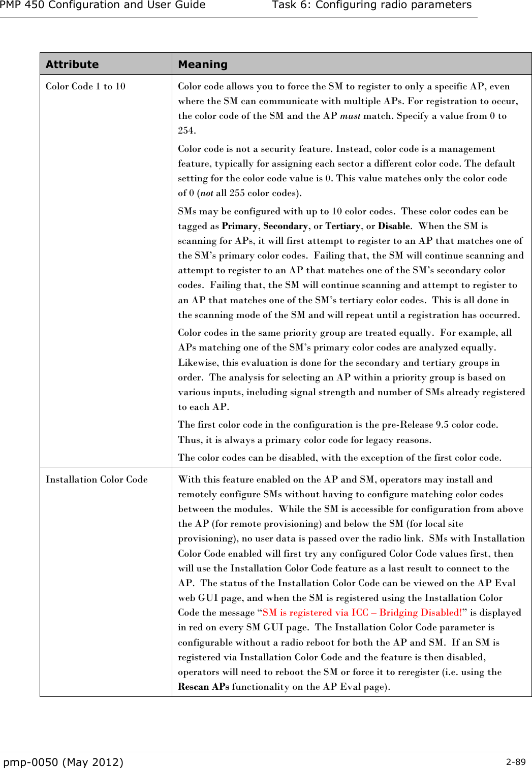
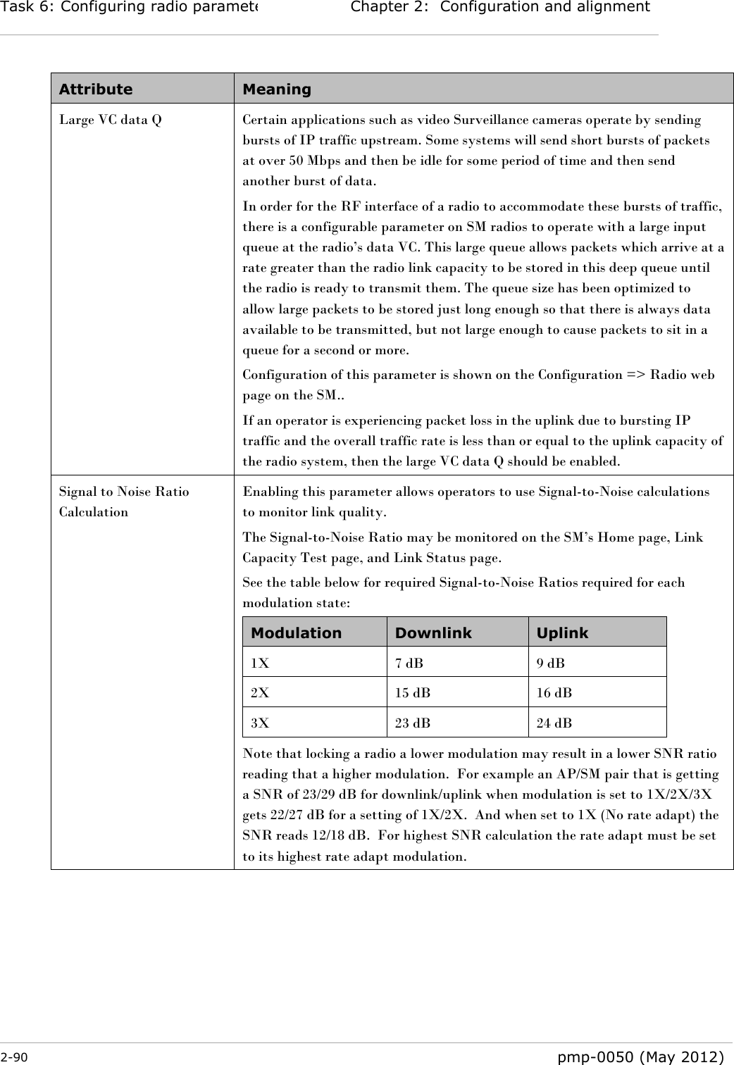
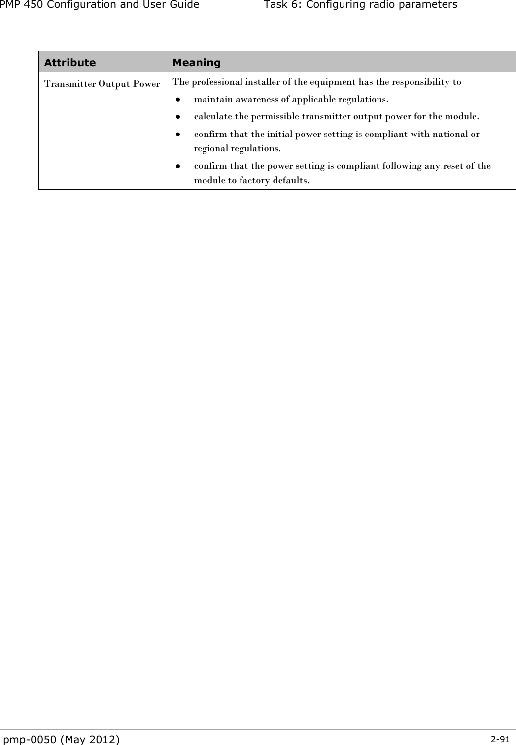
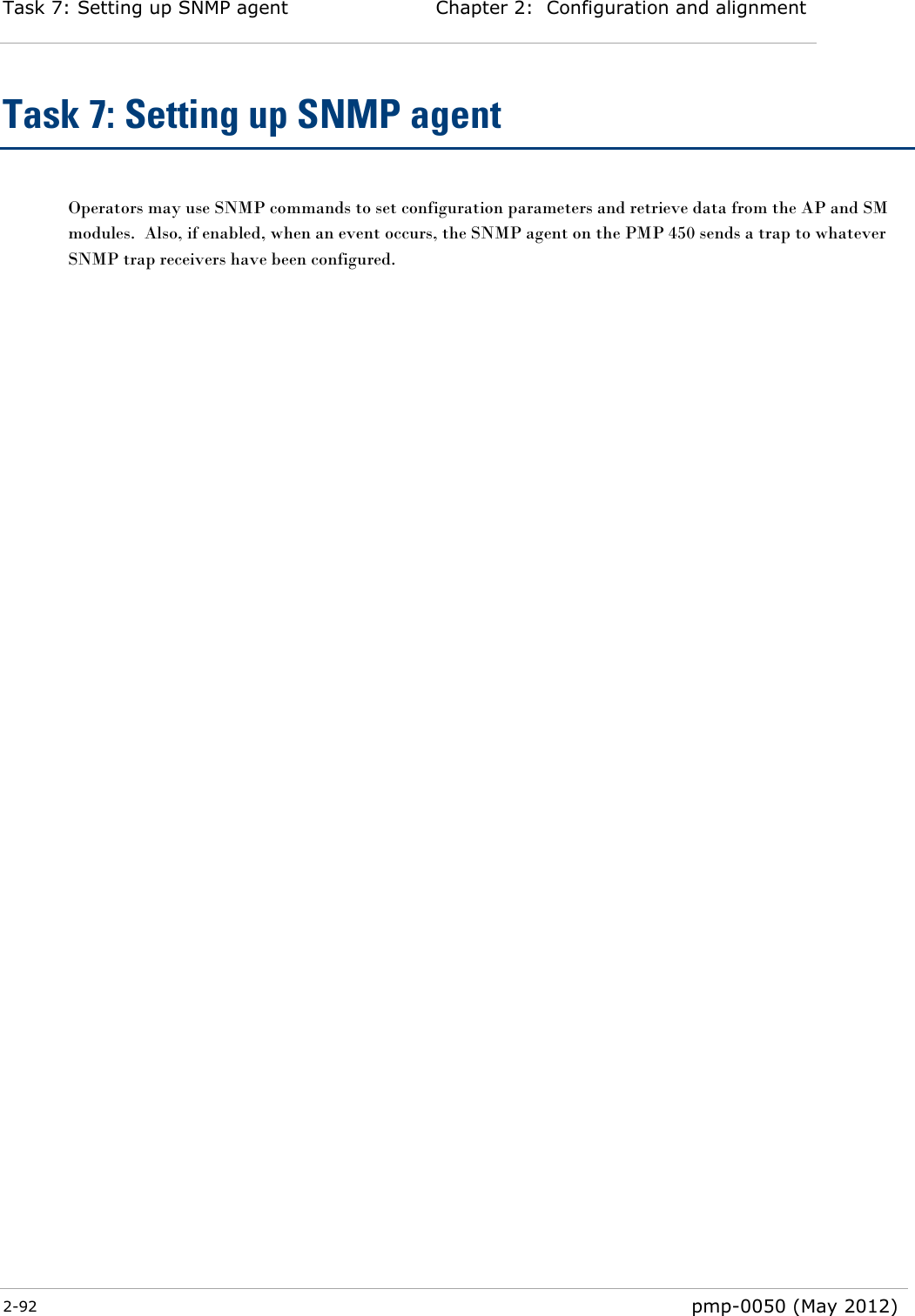
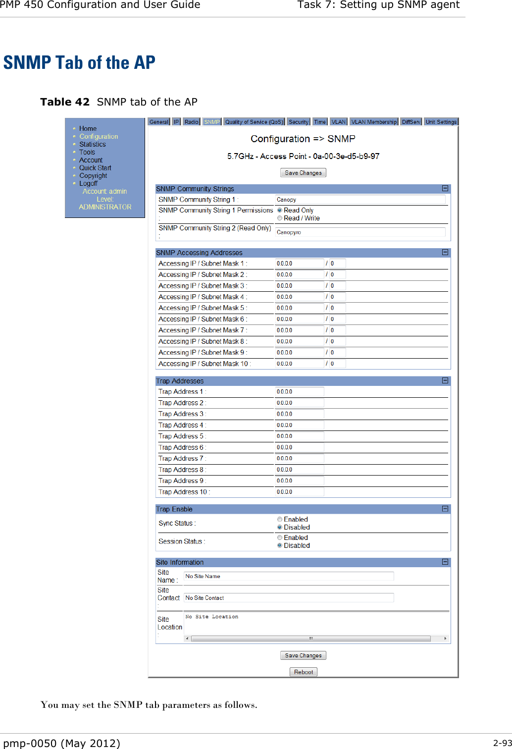
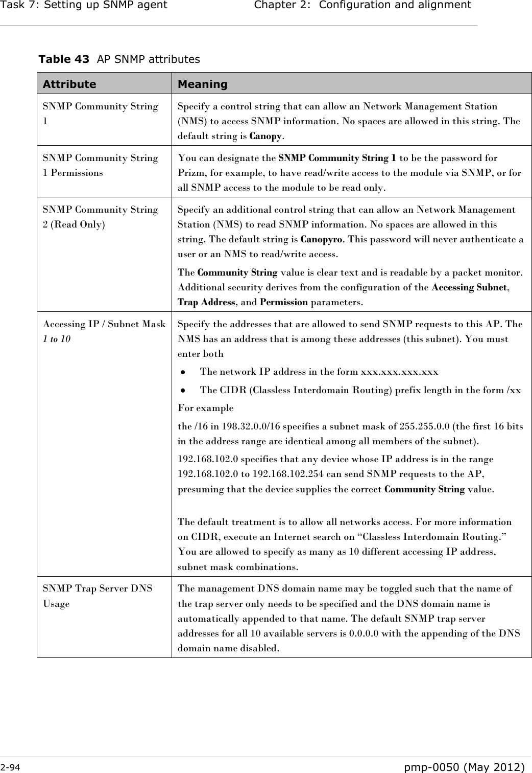
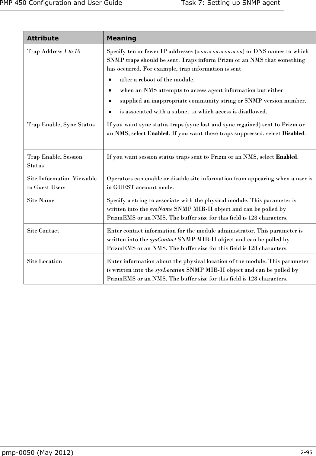
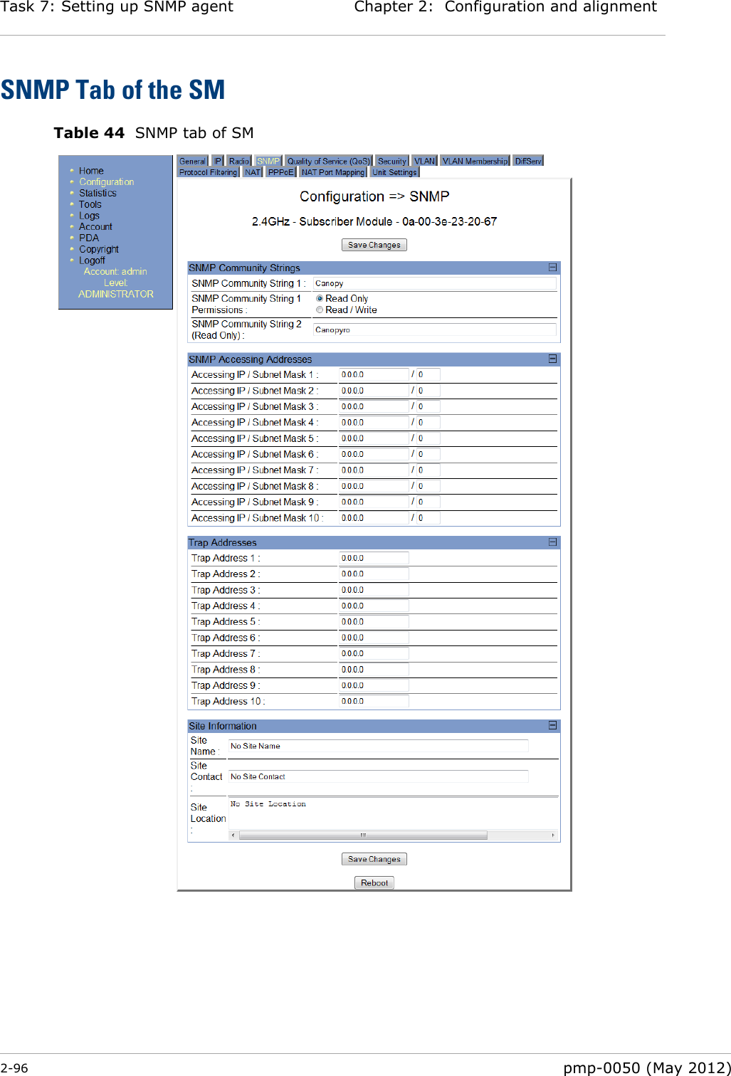
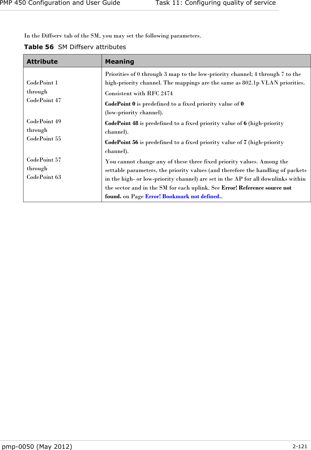
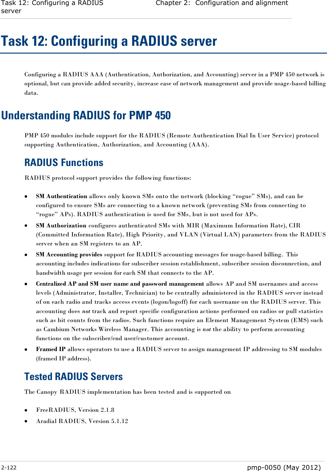
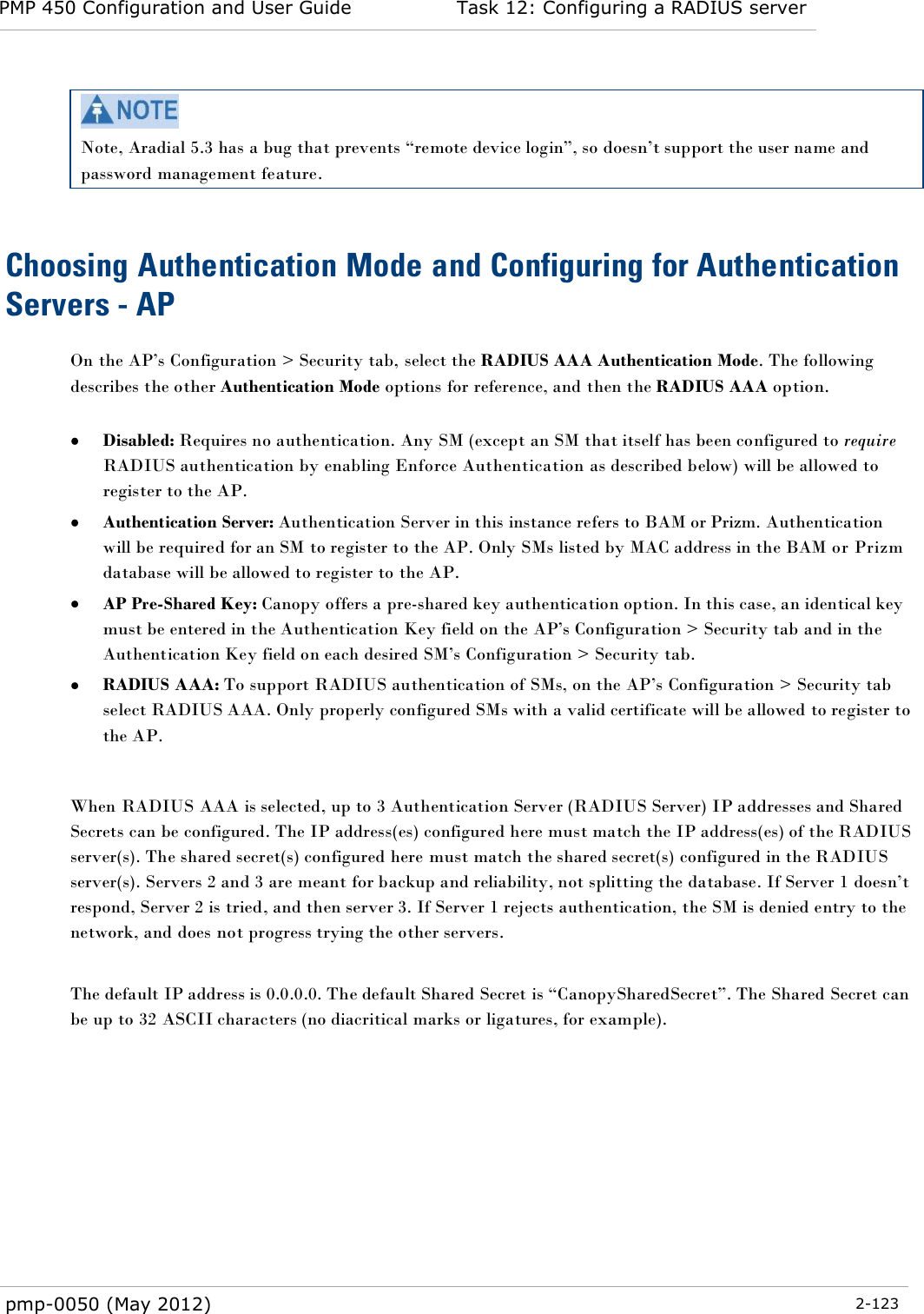
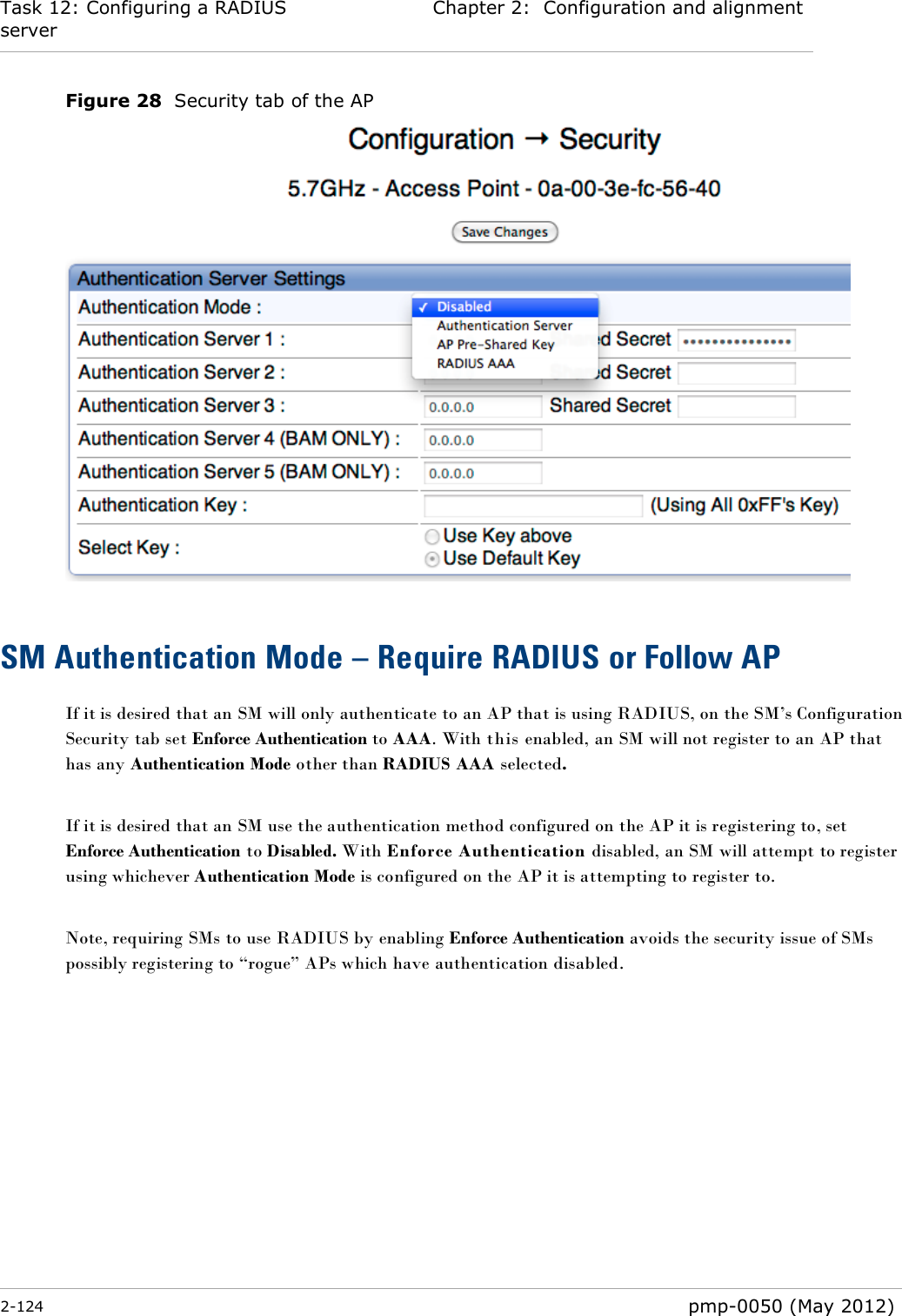
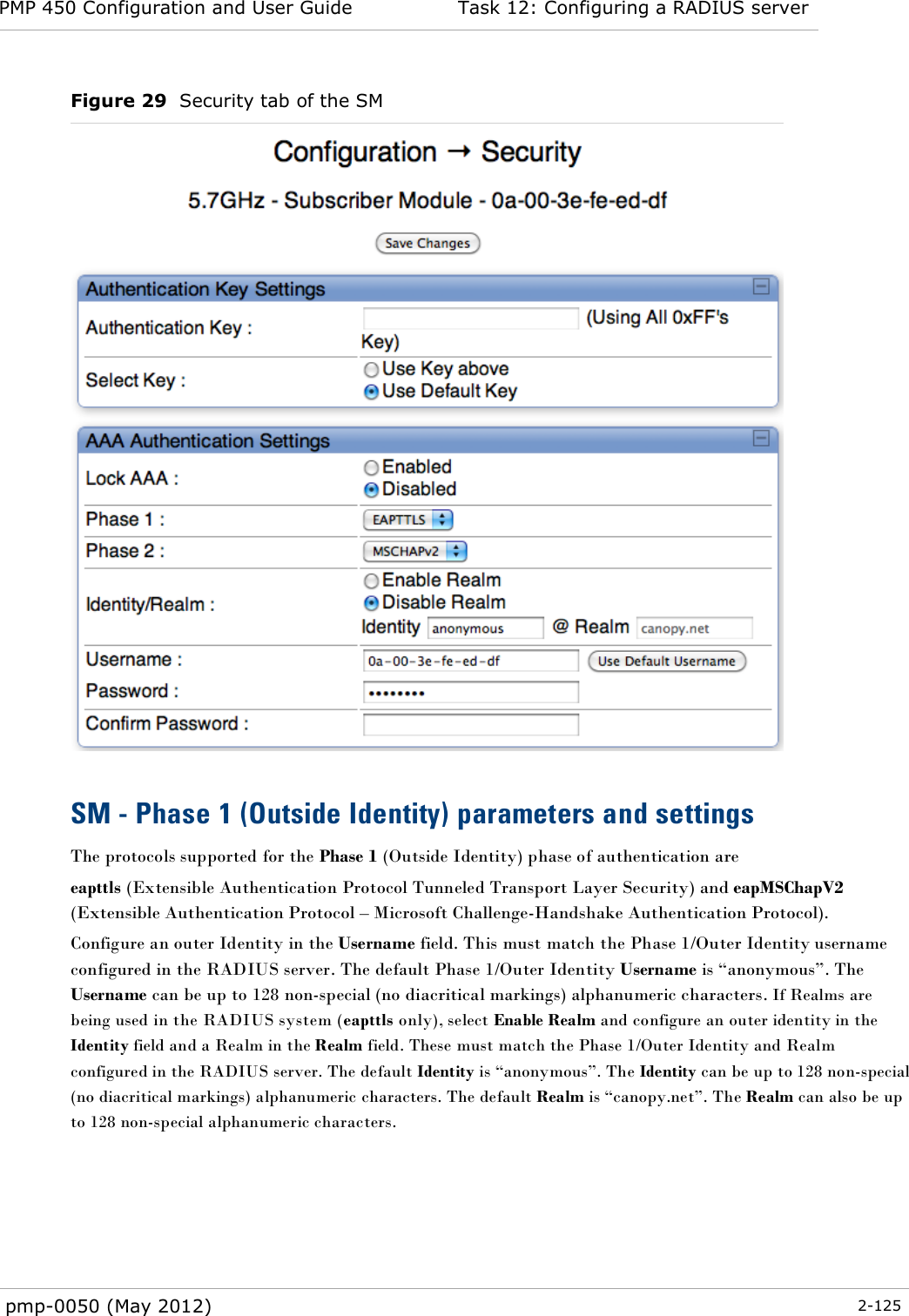
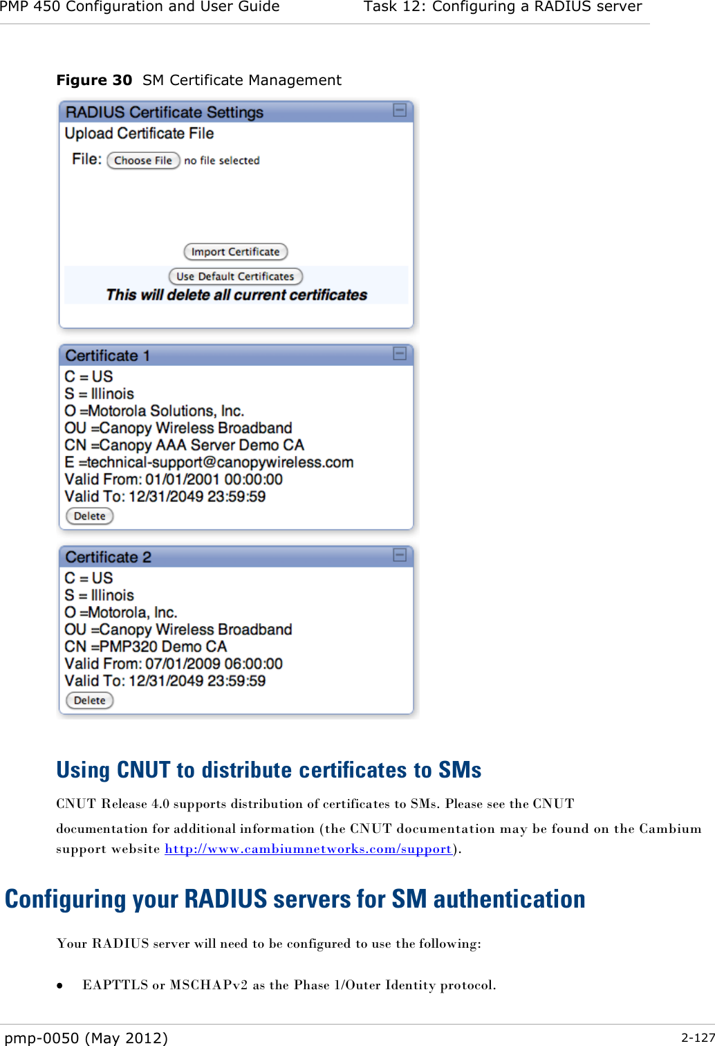
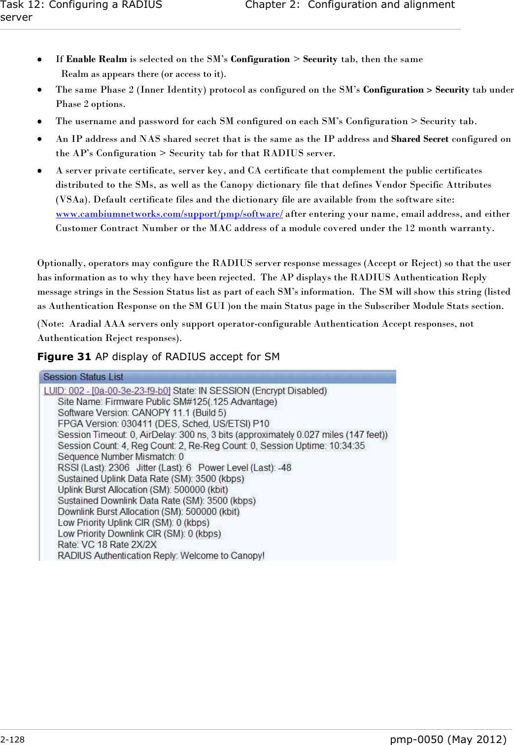
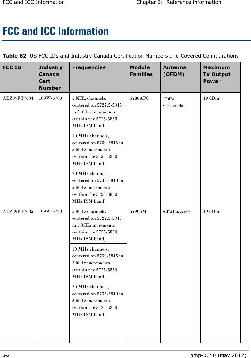
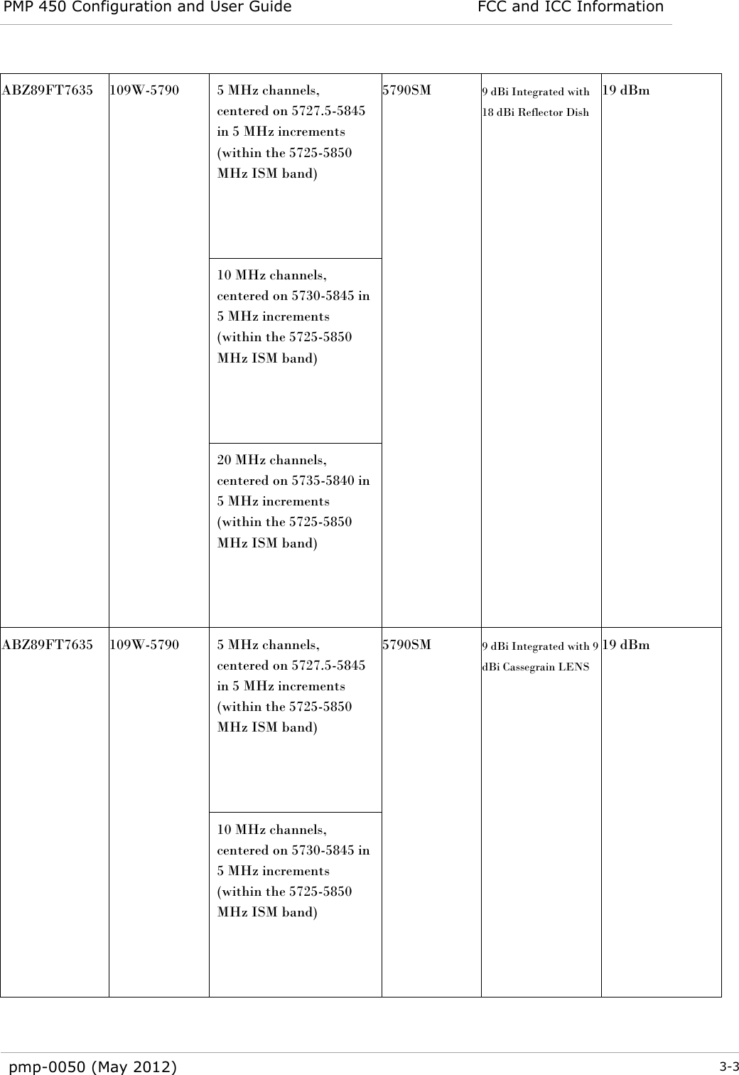
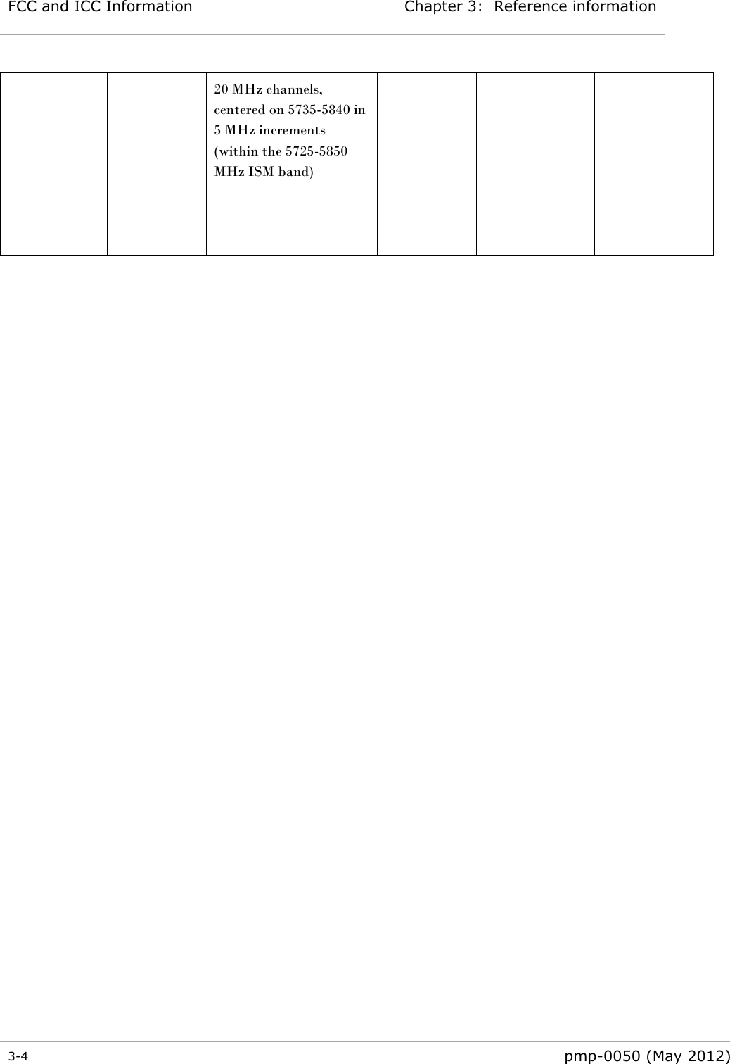
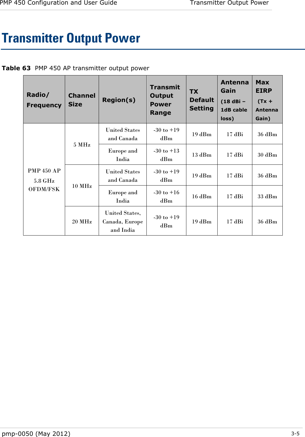
Exhibit D Users Manual per 2 1033 b3