Cambium Networks 89FT0004 Dual Channel 2.4GHz MIMO Access Point Transceiver User Manual PMP 450 Planning Guide
Cambium Networks Inc. Dual Channel 2.4GHz MIMO Access Point Transceiver PMP 450 Planning Guide
UserManual.wiki
>
Cambium Networks
>
89FT0004 User Manual
Exhibit D Users Manual per 2 1033 b3
Navigation menu
Upload a User Manual
Namespaces
Wiki Guide
HTML
PDF
Info
Views
User Manual
Discussion / Help
Navigation
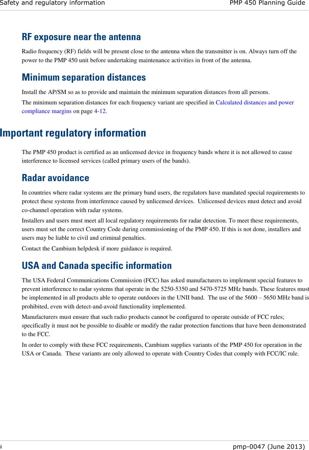

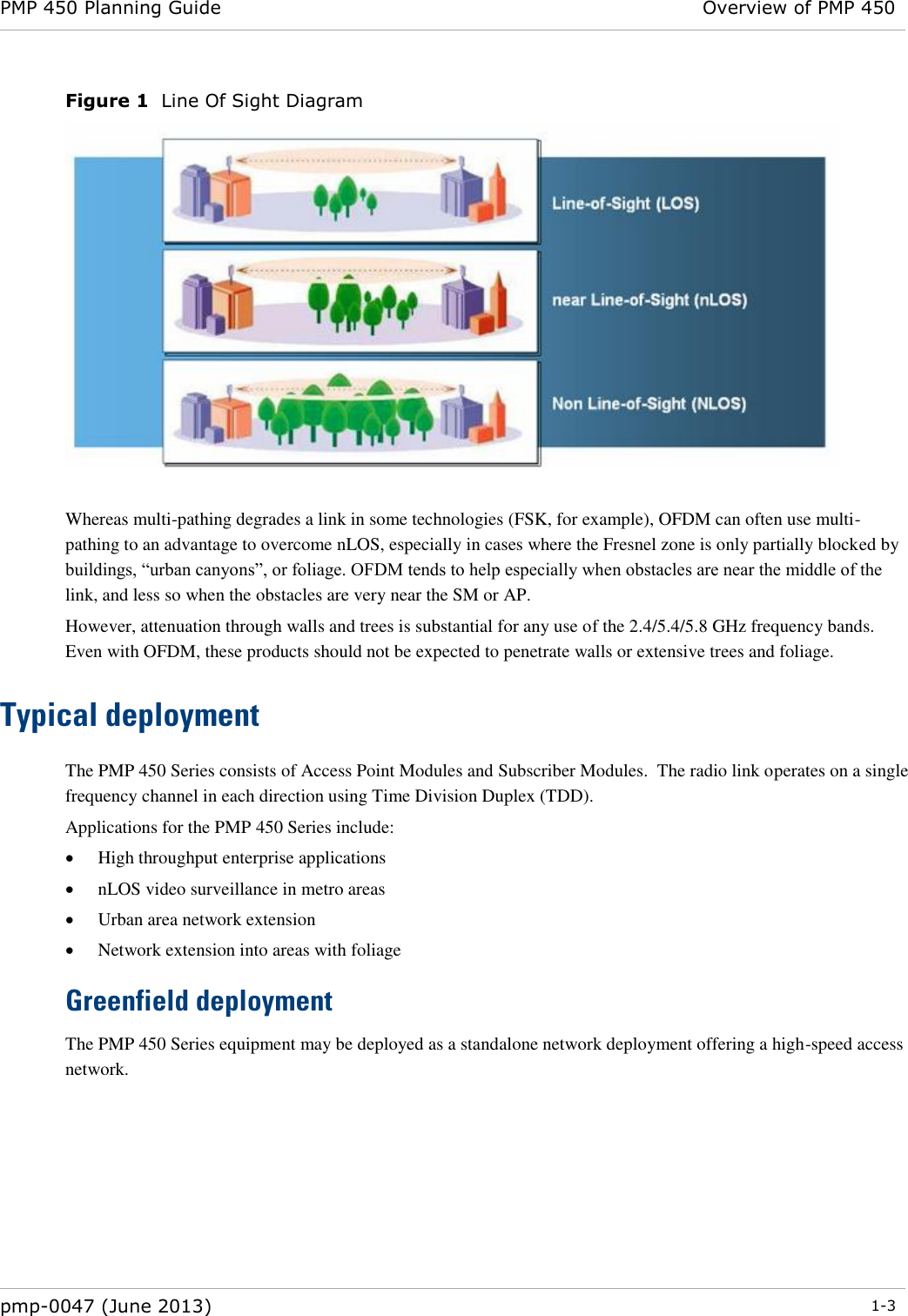
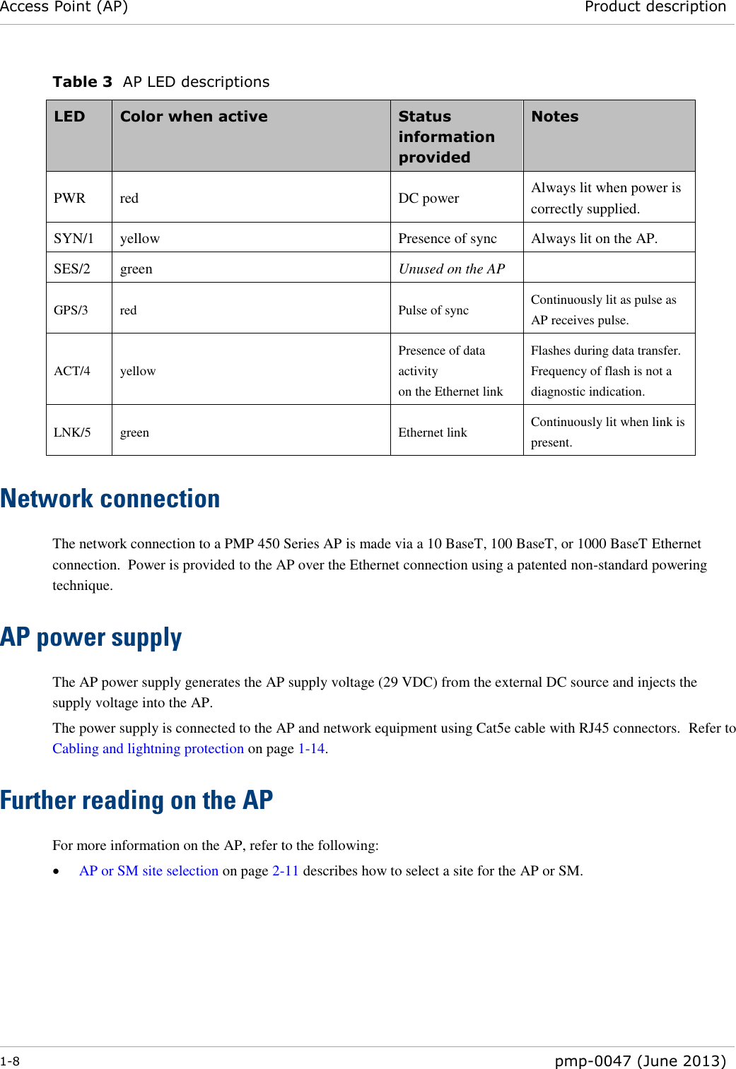
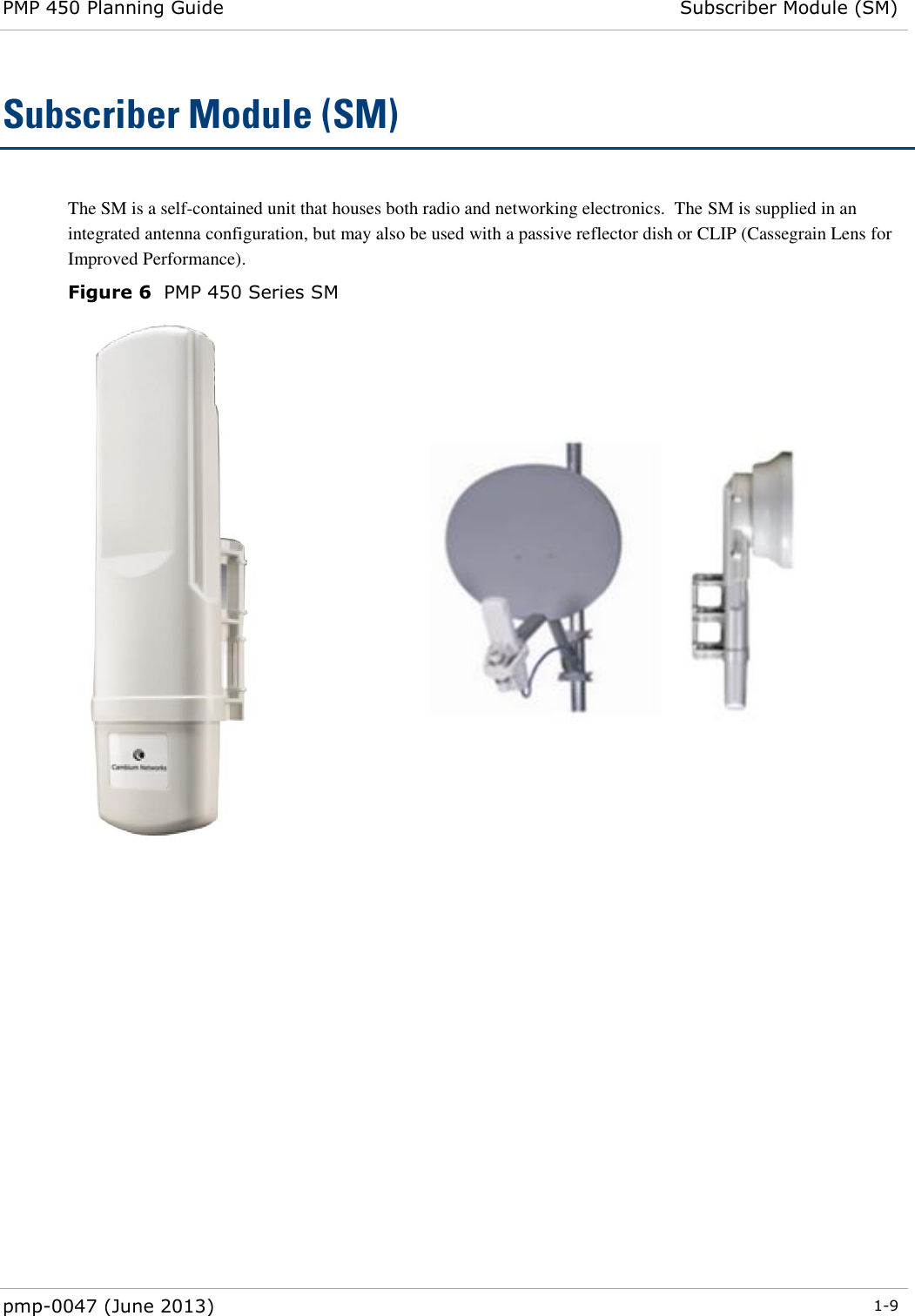
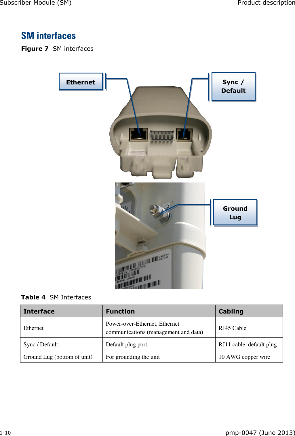
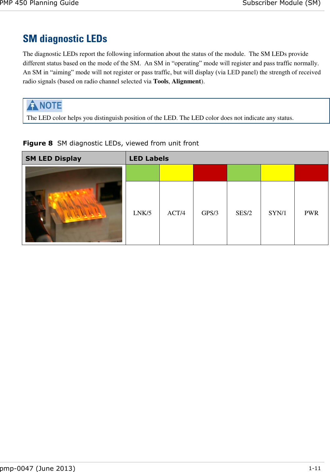
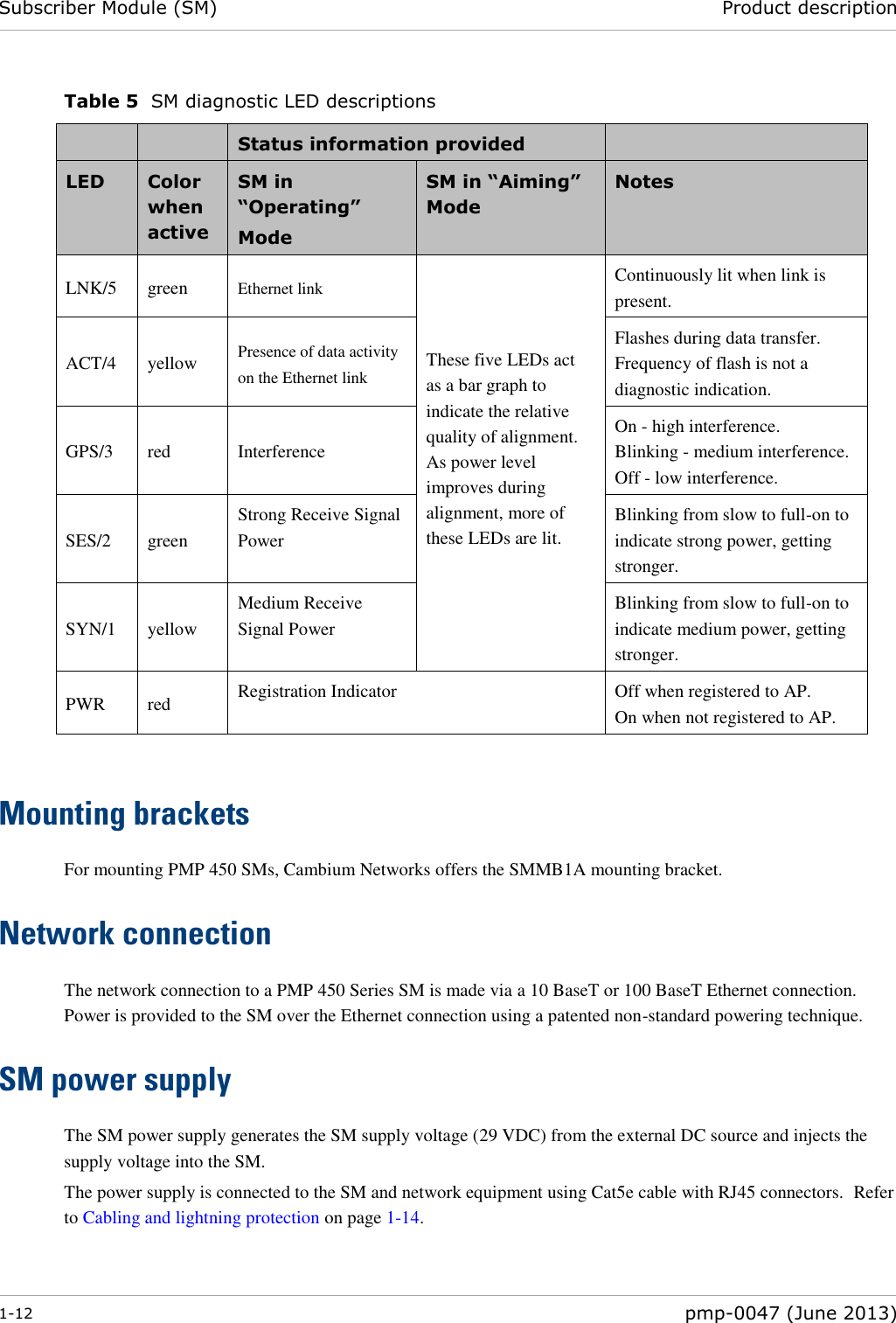
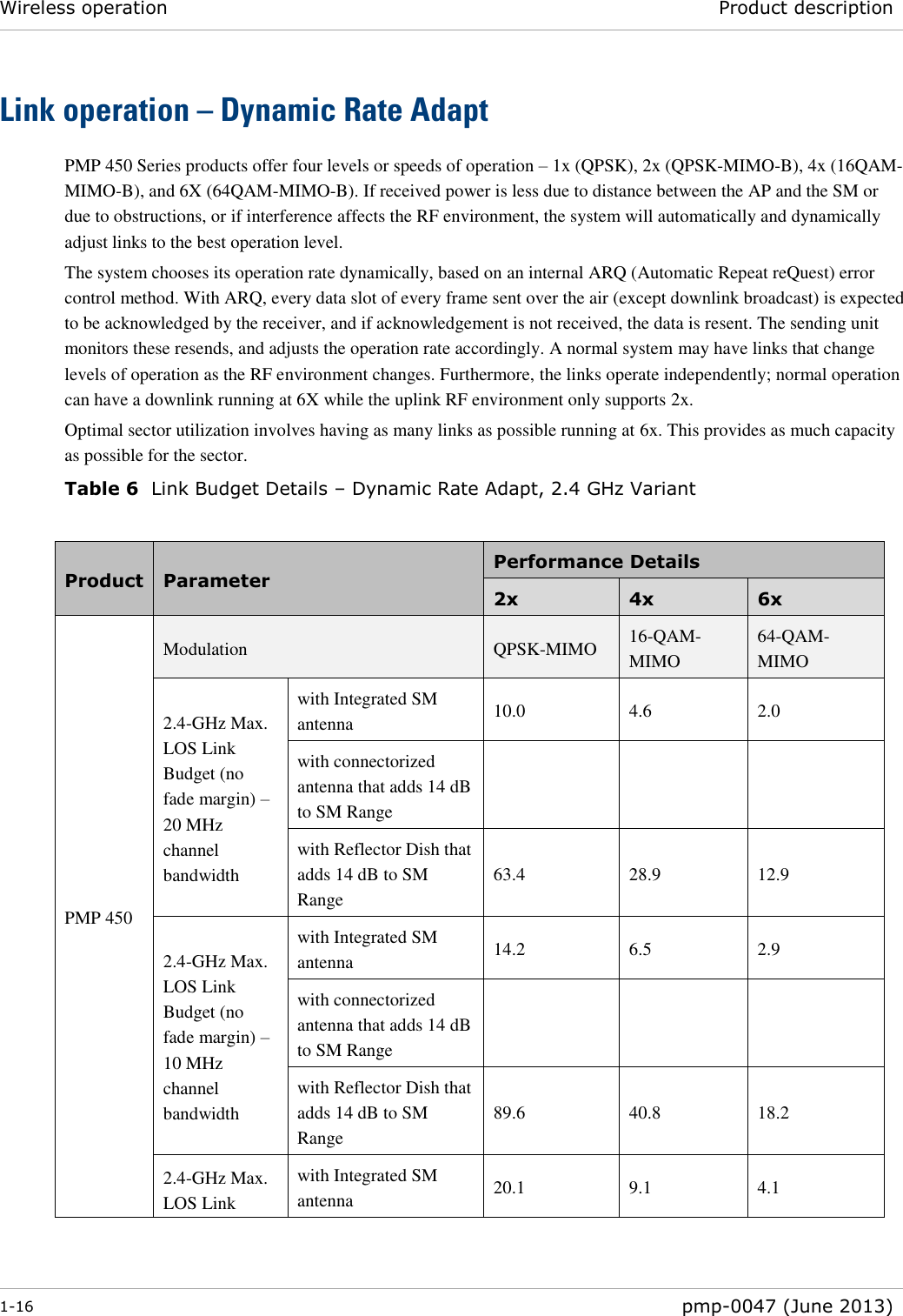
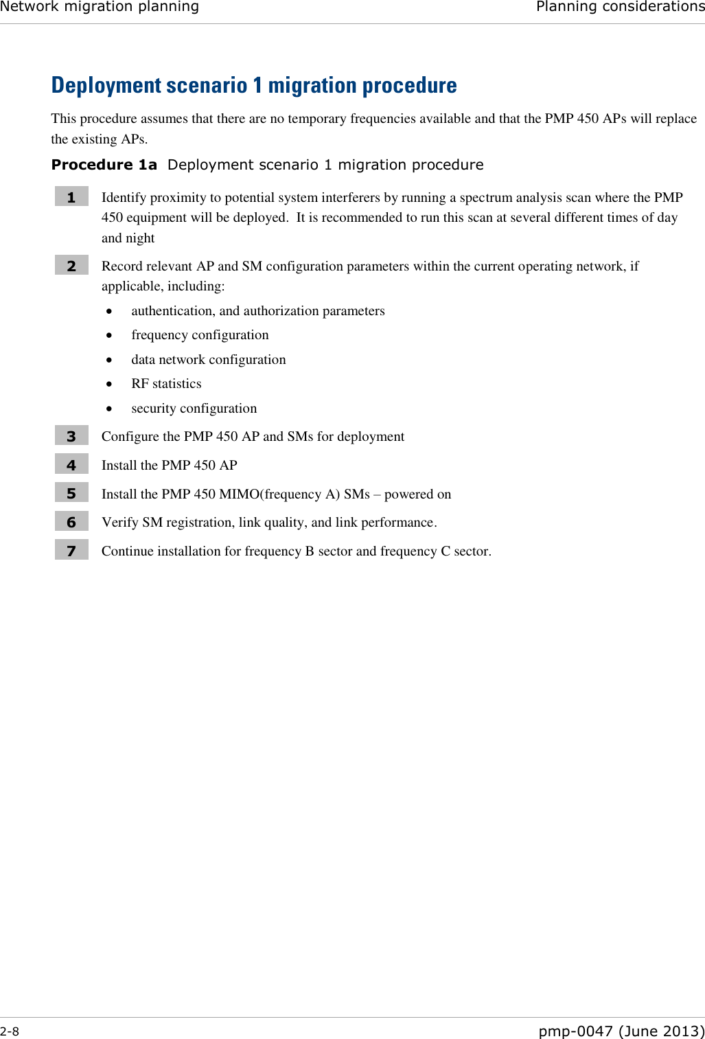
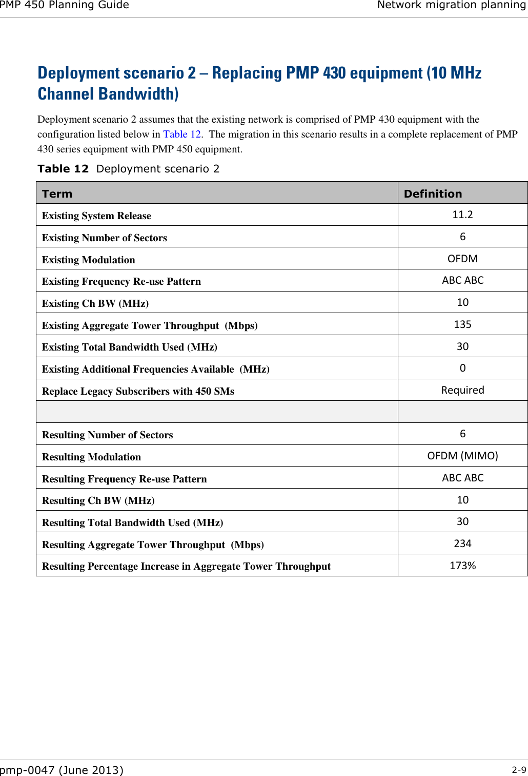
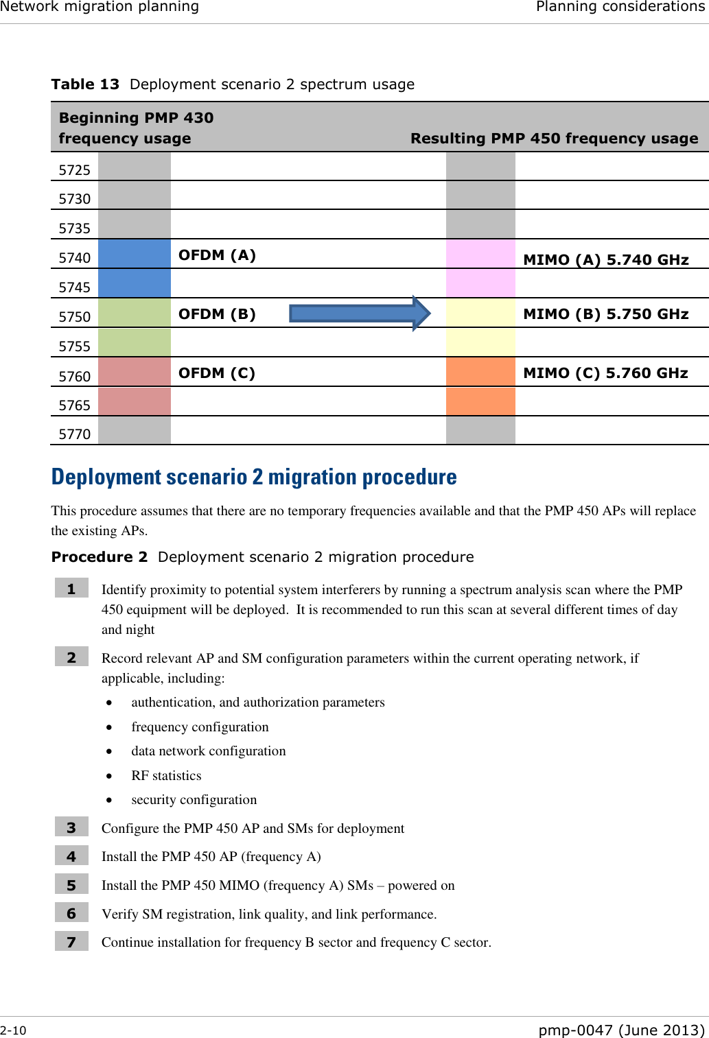
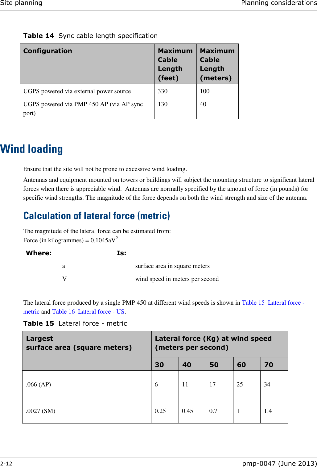
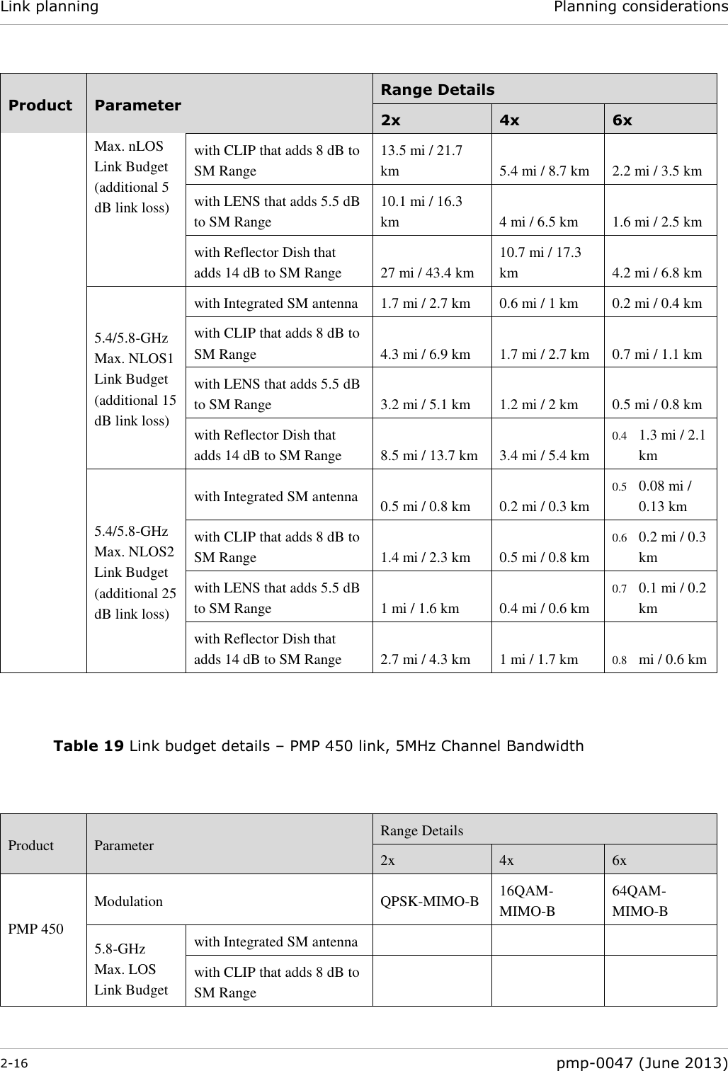
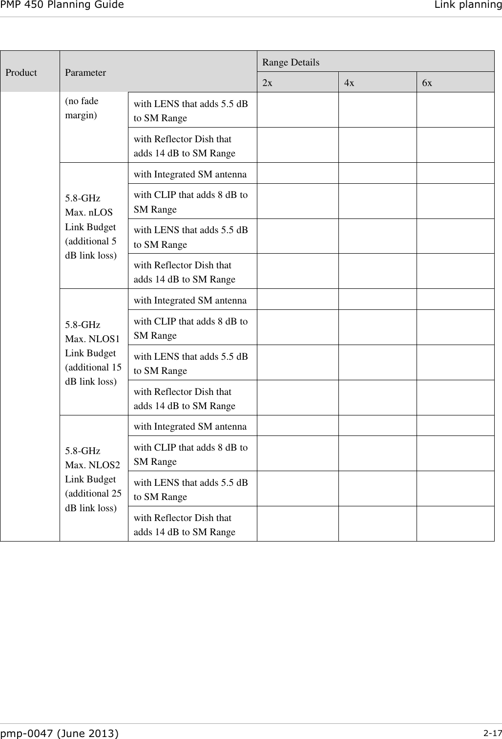
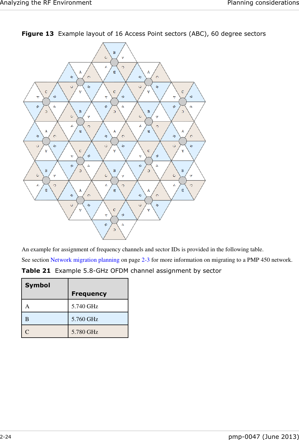
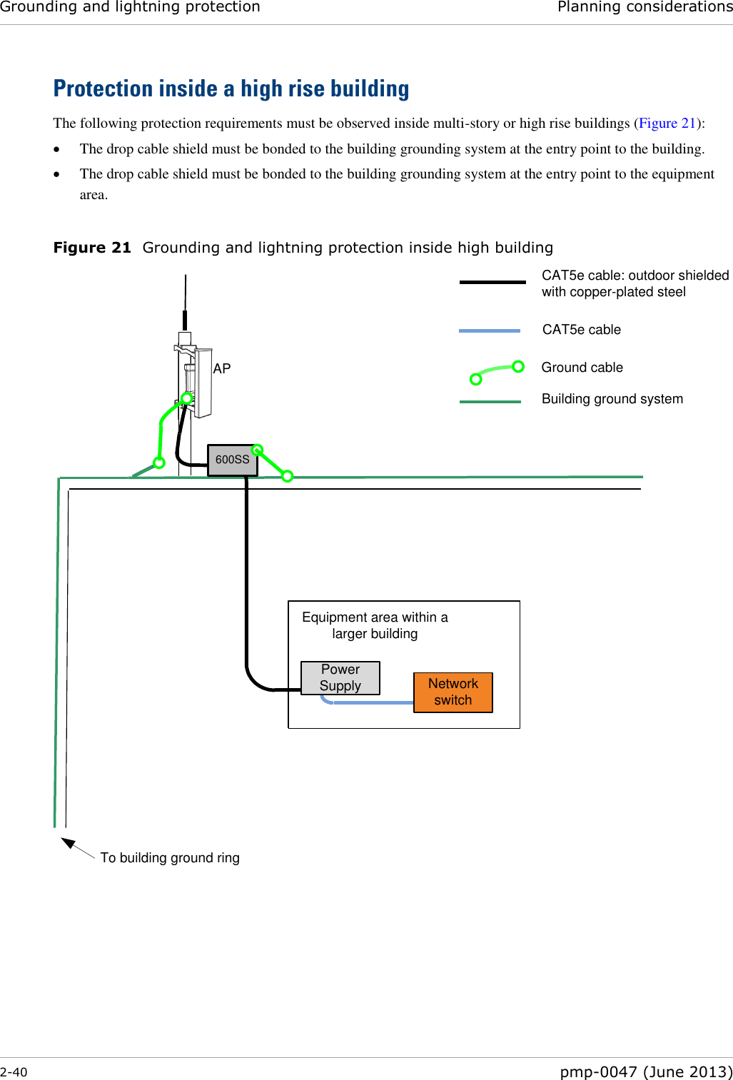
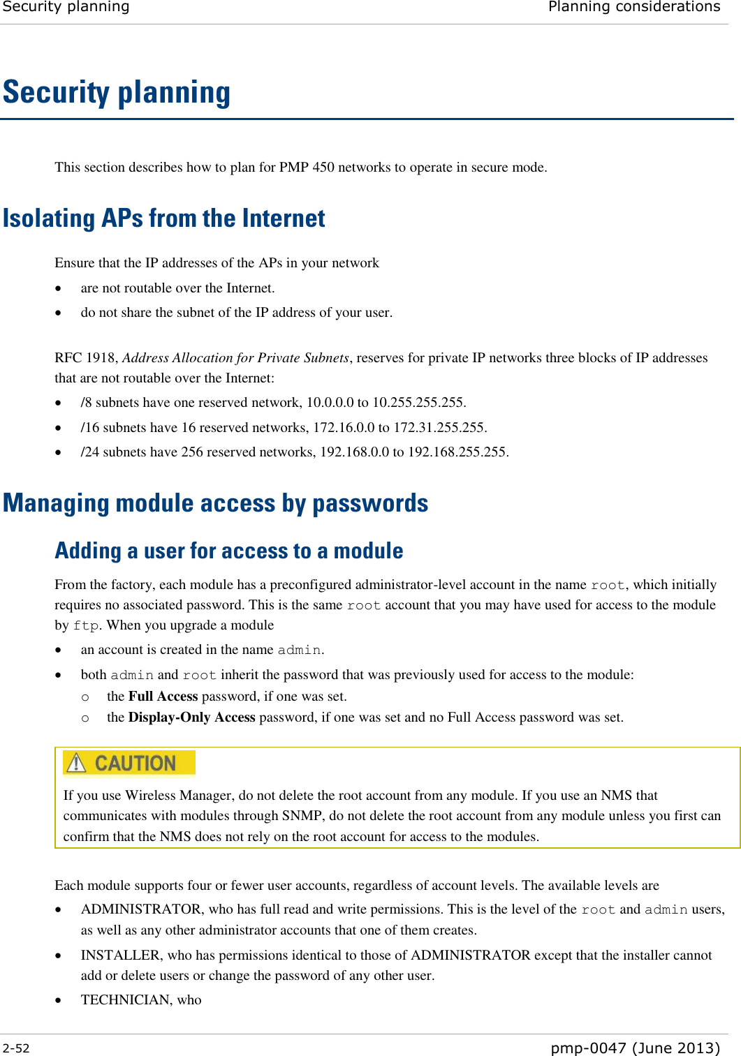
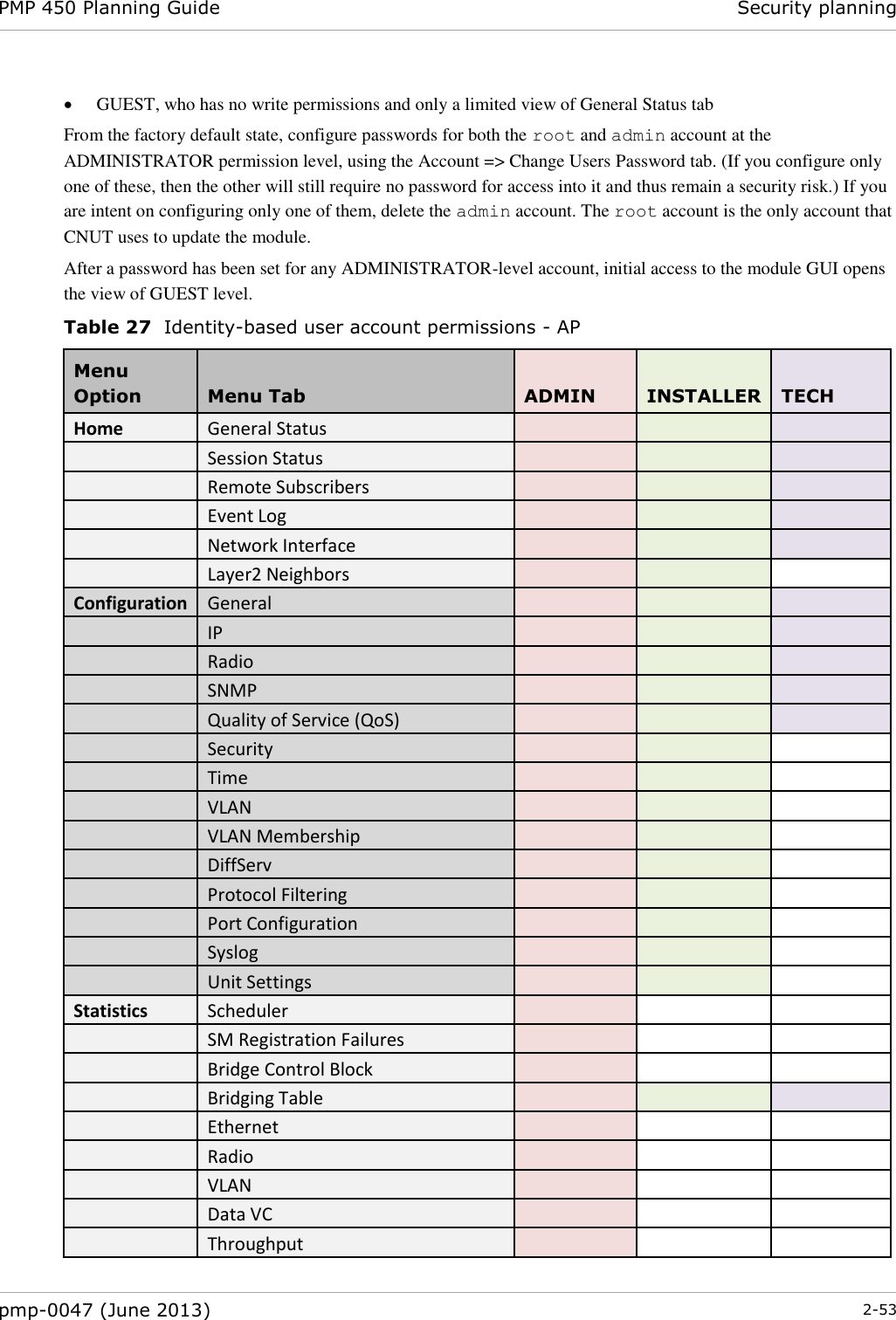
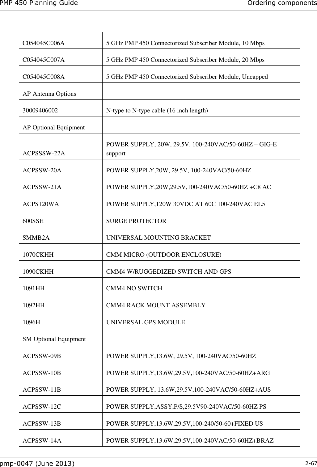
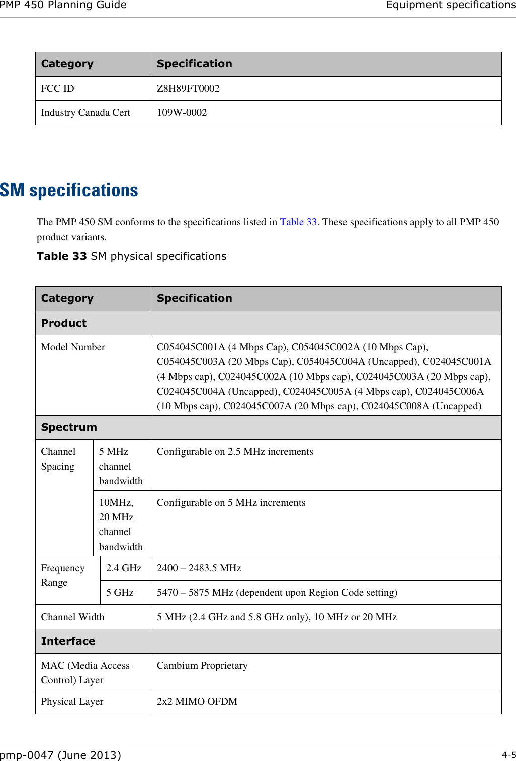
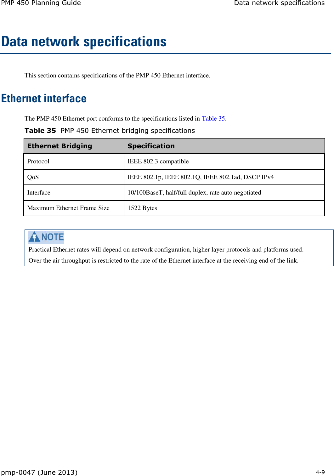
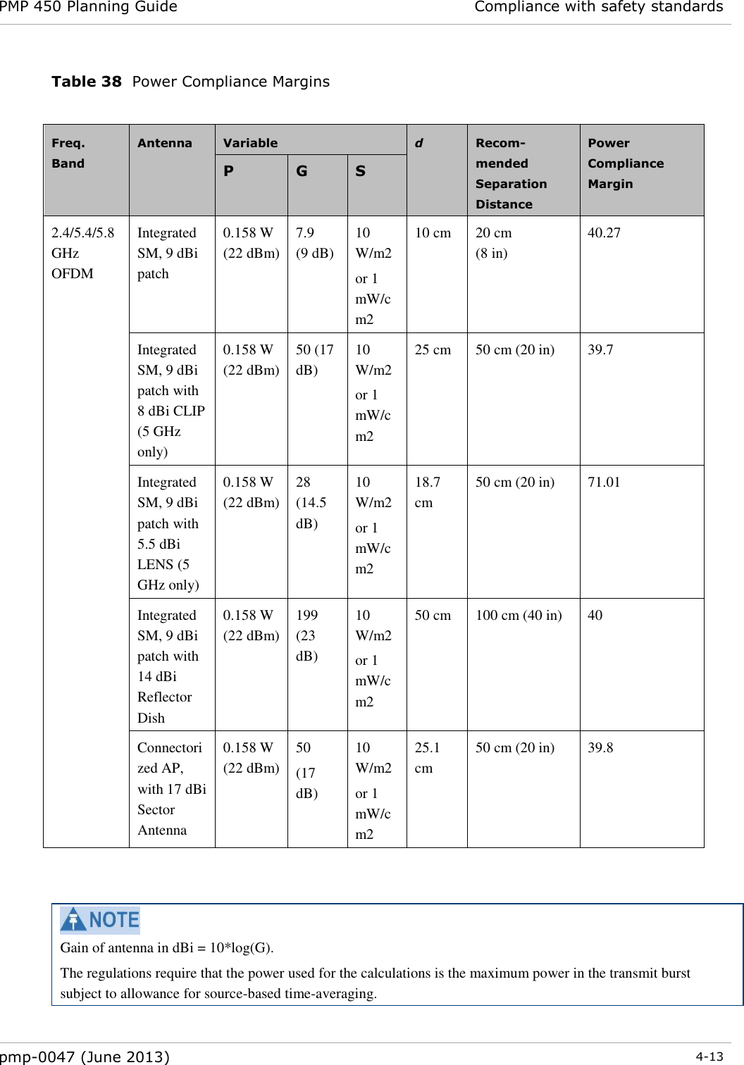
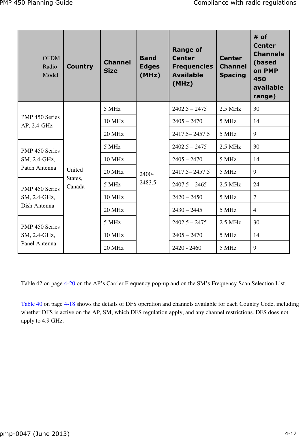
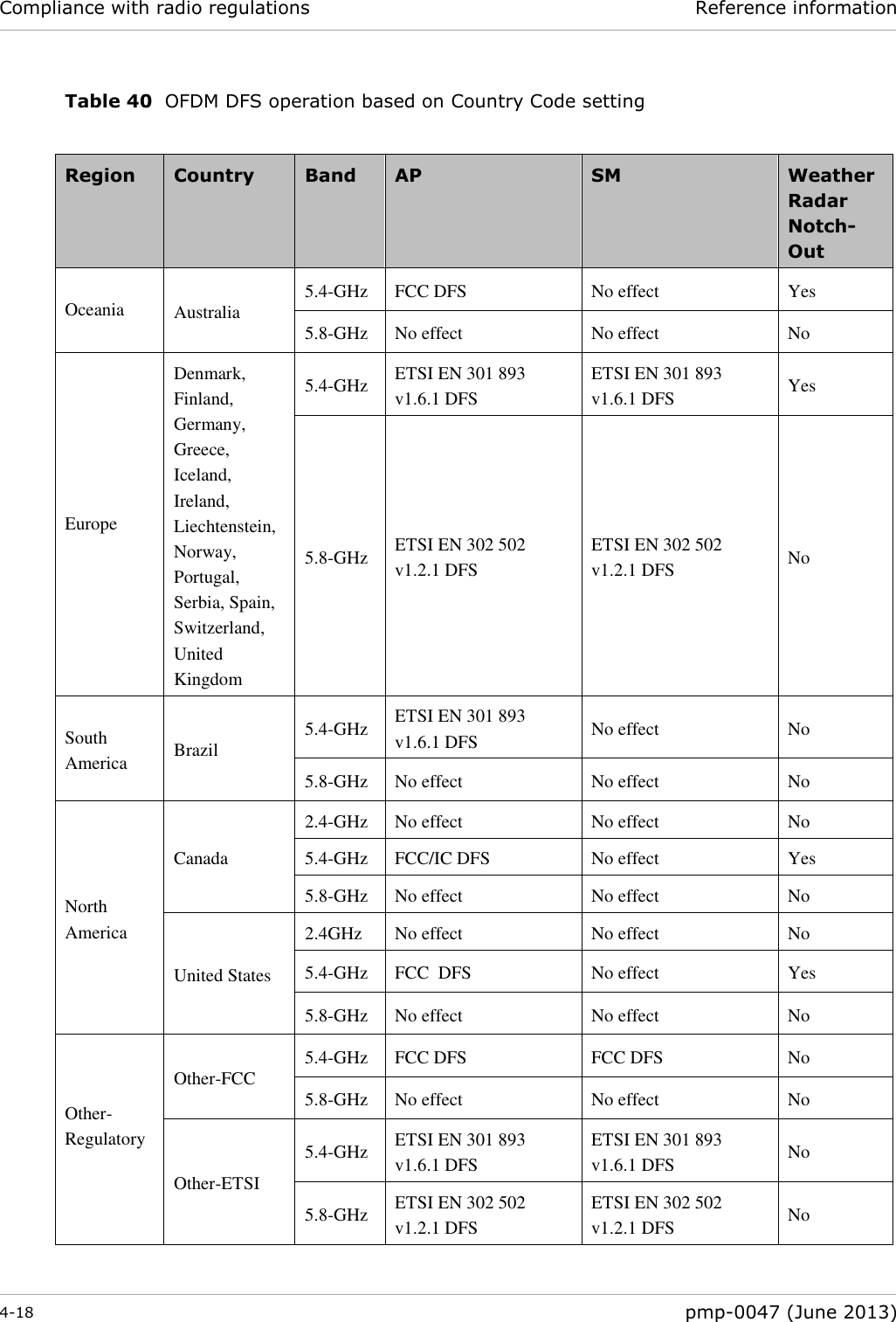
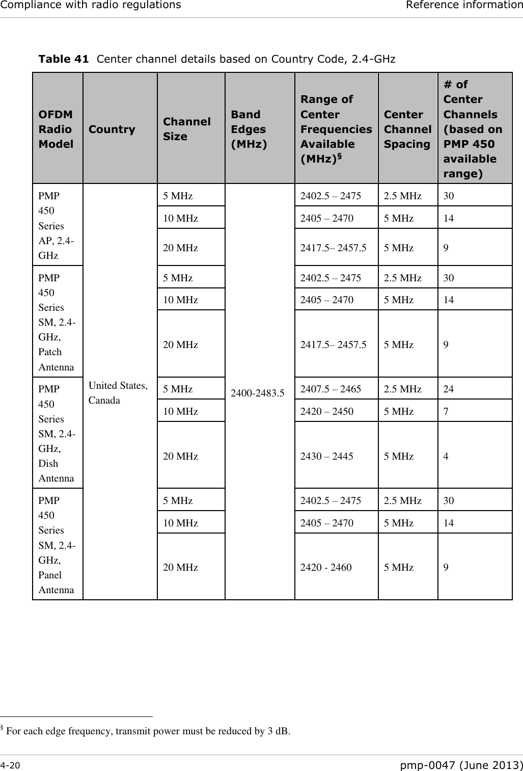
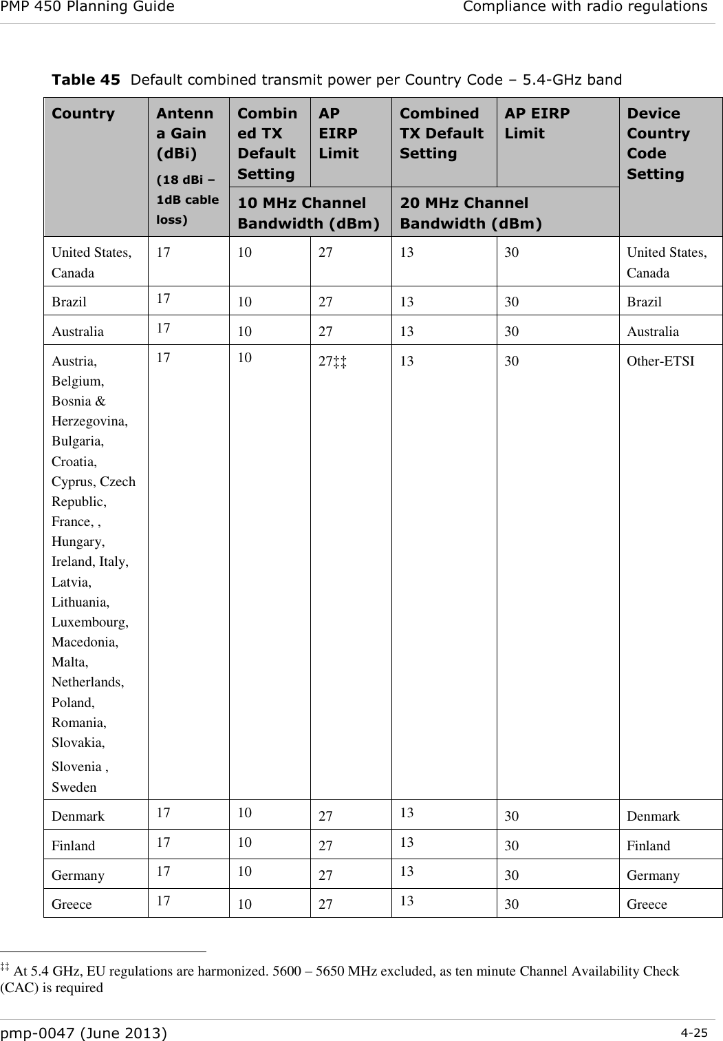
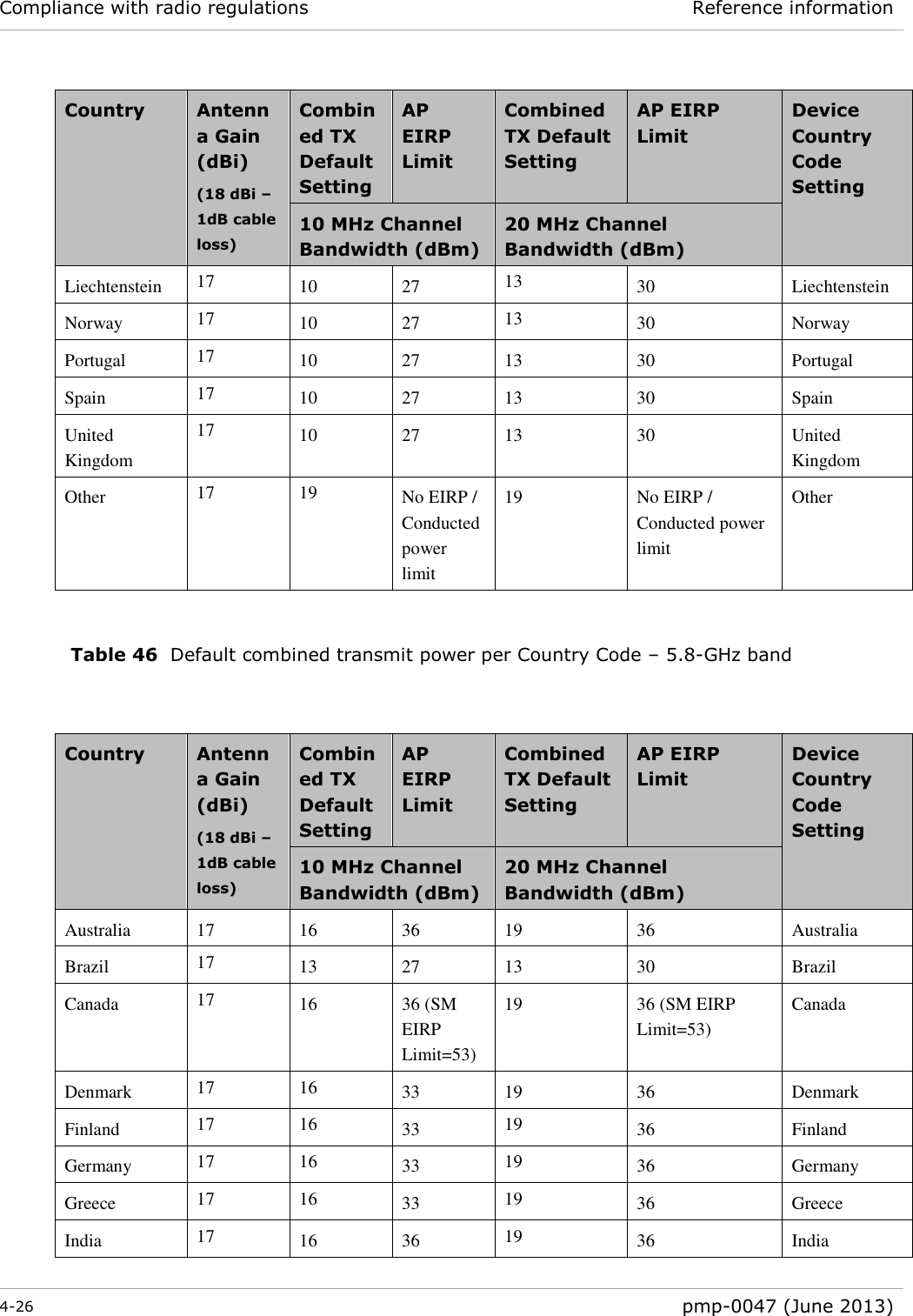
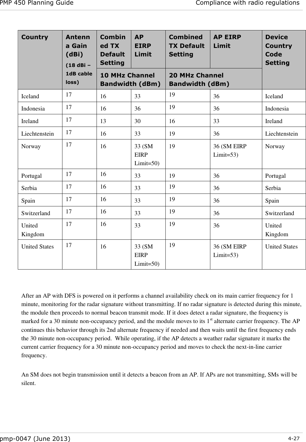
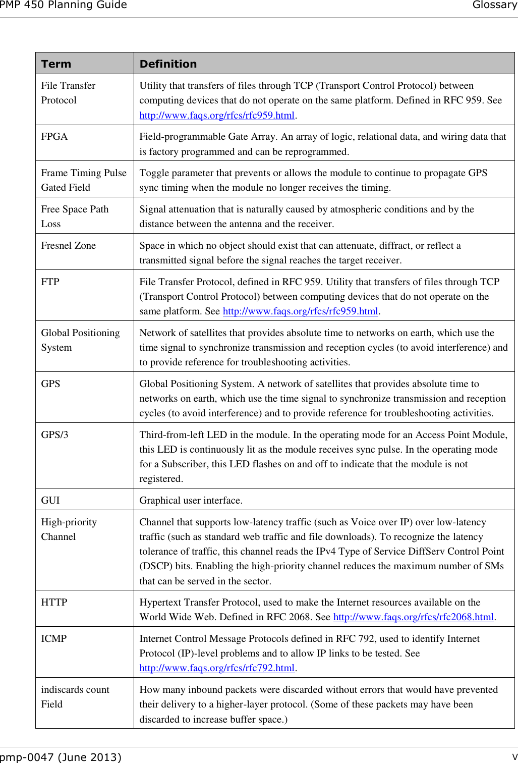
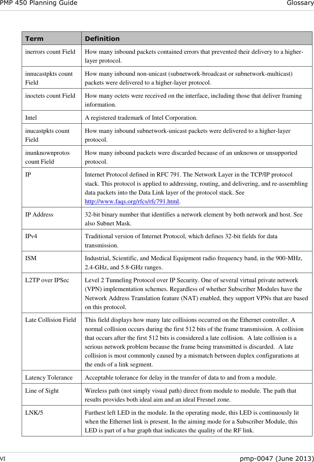
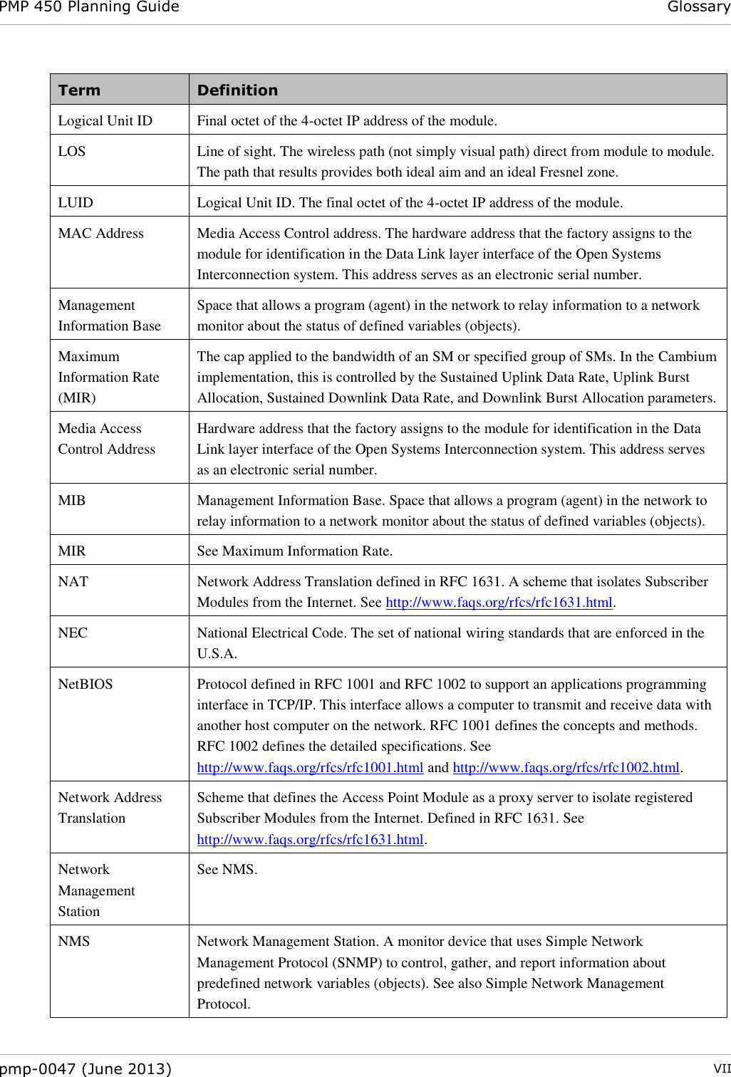
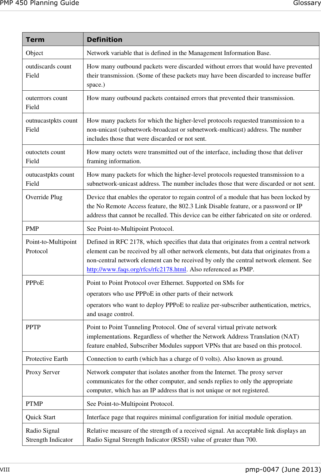
![Security planning Planning considerations 2-62 pmp-0047 (June 2013) Planning for RF Telnet Access Control The RF Telnet Access feature restricts Telnet access to the AP from a device situated below a network SM (downstream from the AP). This is a security enhancement to restrict RF-interface sourced AP access specifically to the LAN1 IP address and LAN2 IP address (Radio Private Address, typically 192.168.101.[LUID]). This restriction disallows unauthorized users from running Telnet commands on the AP that can change AP configuration or modifying network-critical components such as routing and ARP tables. Forwarding Downlink PPPoE PADI packets The AP supports the control of forwarding of PPPoE PADI (PPPoE Active Discovery Initiation) packets. This forwarding is configured on the AP GUI Configuration, Radio tab by parameter PPPoE PADI Downlink Forwarding. When set to “Enabled”, the AP allows downstream and upstream transmission of PPPoE PADI packets. When set to “Disabled”, the AP will NOT allow PPPoE PADI packets to be sent out of the AP RF interface (downstream) but will allow PPPoE PADI packets to enter the RF interface (upstream) and exit the Ethernet interface. Planning for RADIUS integration PMP 450 modules include support for the RADIUS (Remote Authentication Dial In User Service) protocol supporting Authentication, Authorization, and Accounting (AAA). RADIUS Functions RADIUS protocol support provides the following functions: SM Authentication allows only known SMs onto the network (blocking “rogue” SMs), and can be configured to ensure SMs are connecting to a known network (preventing SMs from connecting to “rogue” APs). RADIUS authentication is used for SMs, but is not used for APs. Cambium modules support EAP-TTLS and EAP-MSCHAPv2 authentication methods. SM Configuration: Configures authenticated SMs with MIR (Maximum Information Rate), CIR (Committed Information Rate), High Priority, and VLAN (Virtual LAN) parameters from the RADIUS server when an SM registers to an AP. SM Accounting provides support for RADIUS accounting messages for usage-based billing. This accounting includes indications for subscriber session establishment, subscriber session disconnection, and bandwidth usage per session for each SM that connects to the AP. Centralized AP and SM user name and password management allows AP and SM usernames and access levels (Administrator, Installer, Technician) to be centrally administered in the RADIUS server instead of on each radio and tracks access events (logon/logoff) for each username on the RADIUS server. This accounting does not track and report specific configuration actions performed on radios or pull statistics such as bit counts from the radios. Such functions require an Element Management System (EMS) such as Cambium Networks Wireless Manager. This accounting is not the ability to perform accounting functions on the subscriber/end user/customer account.](https://usermanual.wiki/Cambium-Networks/89FT0004/User-Guide-2006320-Page-110.png)