Cambium Networks 89FT0005 Dual Channel OFDM MIMO Station User Manual ePMP Quick Start
Cambium Networks Inc. Dual Channel OFDM MIMO Station ePMP Quick Start
Exhibit D Users Manual per 2 1033 b3

Cambium
ePMP Quick Start
Guide
System Release Beta
ePMP Series Model Numbers
This Quick Start Guide may be referenced for the following Cambium ePMP equipment:
Model
Description
N000900L001A
ePMP Pwr Supply for GPS Radio - no cord (spare)
N000900L002A
ePMP Pwr Supply for non-GPS Radio - no cord (spare)
C050900A011A
ePMP GPS, Conn - 5 GHz - no power cord
C058900A112A
ePMP GPS, Conn - 5 GHz - US power cord - FCC version
C050900A021A
ePMP Conn - 5 GHz - no power cord
C058900A122A
ePMP Conn - 5 GHz - US power cord - FCC version
C050900C031A
ePMP Integ(16dBi) - 5 GHz - no power cord
C058900C132A
ePMP Integ(16dBi) - 5 GHz - US power cord - FCC version
C050900D001A
ePMP Omni Antenna - 5 GHz
C050900D002A
ePMP Sector 120 Antenna - 5 GHz
C050900D003A
ePMP Sector 90 Antenna - 5 GHz
C050900D004A
ePMP High Gain Panel Antenna - 5 GHz
ePMP Quick Start Guide
2
pmp-0364 000v006 (July 2013)
About this Guide
Thank you for choosing Cambium Networks for your Point-to-Multipoint networking solution.
This guide describes:
ePMP Hardware Components
Installation
Accessing the Mangement GUI / Initial
Link Bring-up
Specifications / General Information
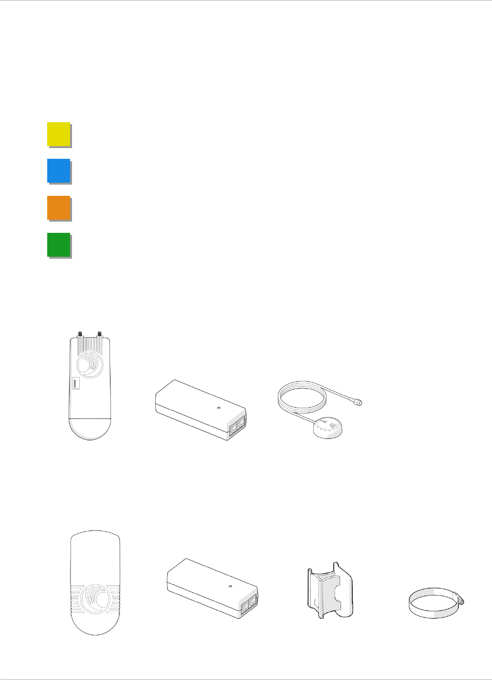
Package Contents, AP
Radio
Power Supply
GPS Antenna
Package Contents, STA
Radio
Power Supply
Mounting Bracket
Strap
Overview of ePMP Hardware
ePMP Quick Start Guide
1
pmp-0364 000v006 (July 2013)
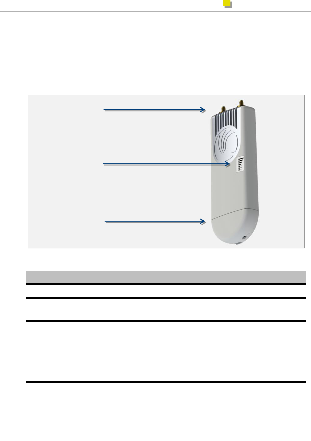
Overview of ePMP Hardware
This section describes the key components of the ePMP Access Point and Station modules.
Access Point Hardware
Access Point LED Indicators
Label
Function
POWER
Lit green when power is applied to the device.
GPS
SYNC
Lit green when the AP has acquired a valid synchronization signal from a CMM or from
its internal GPS.
ETH
Lit red when the Ethernet link is established at a 10 Mbps rate, blinks when traffic is
sent over the Ethernet interface.
Lit green when the Ethernet link is established at a 100 Mbps rate, blinks when traffic
is sent over the Ethernet interface.
Lit red and green when the Ethernet link is established at a 1000 Mbps rate, blinks
when traffic is sent over the Ethernet interface.
RF Signal
(3 LEDs)
TBD
External
antenna ports
(50Ω, SMA)
LED
Indicators
Removable
Lower Shell
(for Ethernet
port access)
Overview of ePMP Hardware
ePMP Quick Start Guide
2
pmp-0364 000v006 (July 2013)
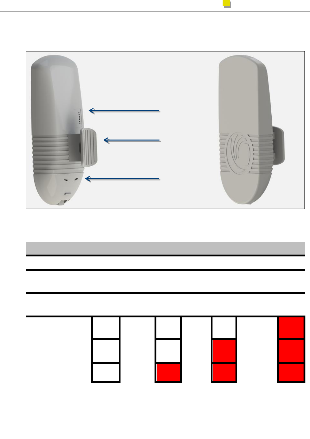
Station Hardware
Station LED Indicators
Label
Function
POWER
Lit green when power is applied to the device.
ETH1
Lit green when Ethernet link is established at 10 Mbps or 100 Mbps, and blinks as traffic
is sent over “Main” Ethernet interface.
ETH2
Lit green when Ethernet link is established at 10 Mbps or 100 Mbps, and blinks as traffic
is sent over “Secondary” Ethernet interface.
RF
Signal
(3 LEDs)
Rx Signal
Strength
less than
or equal
to -80
dBm
OFF
Rx Signal
Strength
between -
80 dBm
and -70
dBm
OFF
Rx
Signal
Strength
between
-70 dBm
and -60
dBm
OFF
Rx signal
strength
greater than
-60 dBm
ON
OFF
OFF
ON
ON
OFF
ON
ON
ON
LED
Indicators
Mounting
Bracket
Removable
Lower Shell (for
Ethernet port
access)
Powering On the Access Point
ePMP Quick Start Guide
1
pmp-0364 000v006 (July 2013)
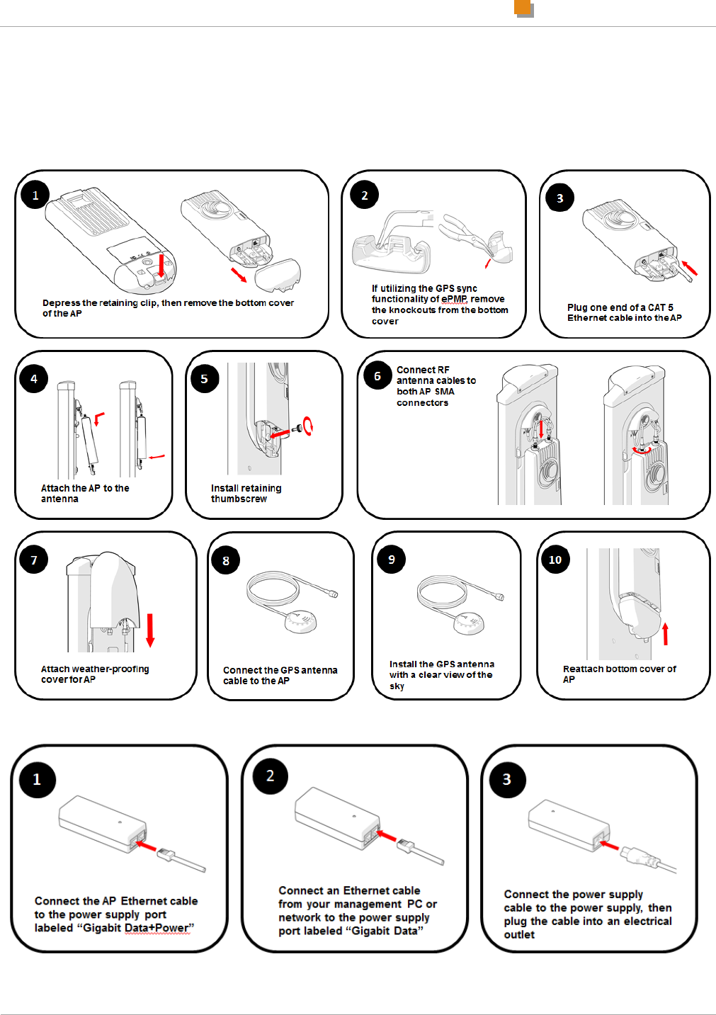
Installing the Access Point
The ePMP Access Point is designed to attach to a Cambium antenna or to be pole-mounted (for use with a non-
Cambium antenna).
Powering On the Access Point
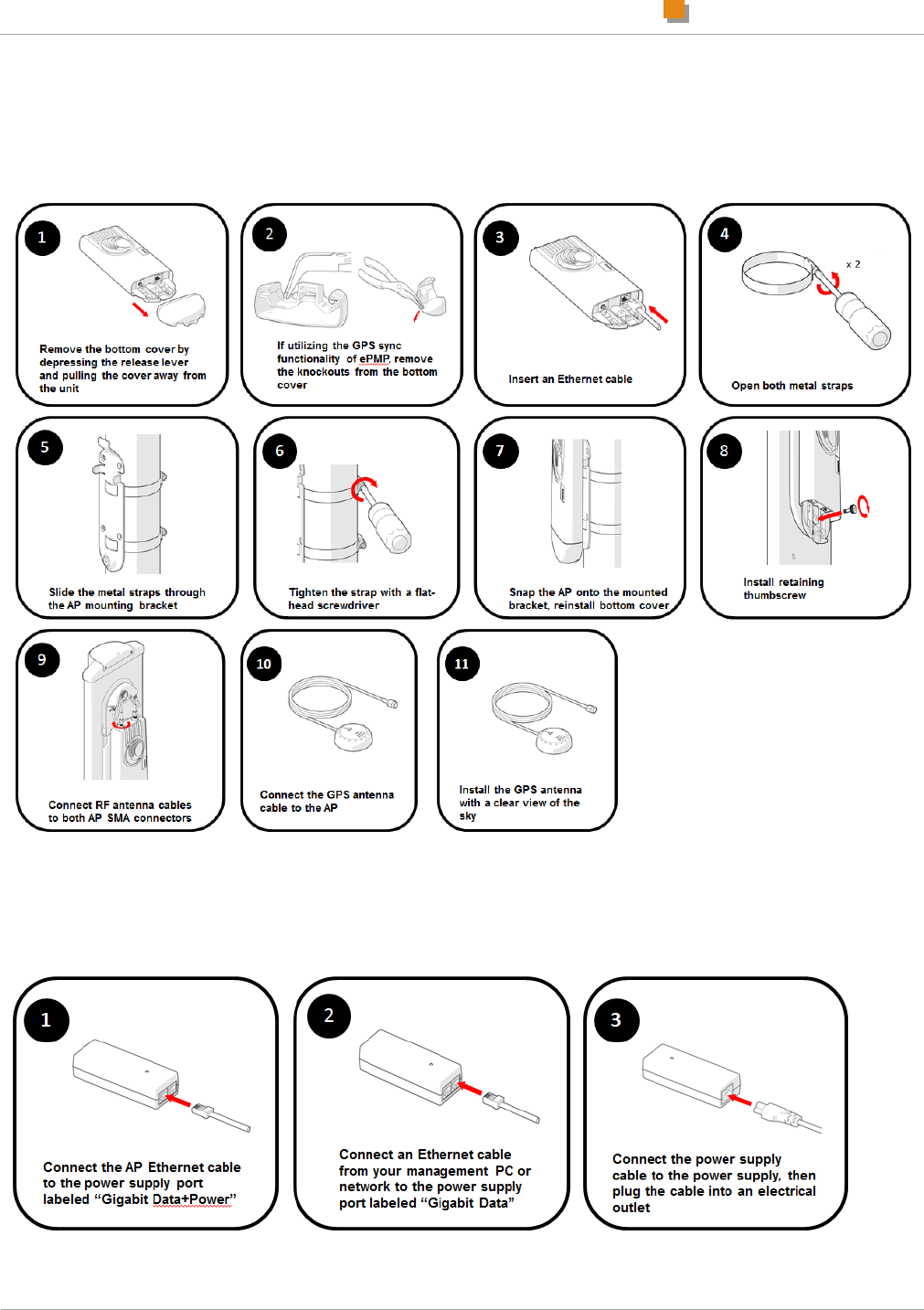
Powering On the Access Point
ePMP Quick Start Guide
2
pmp-0364 000v006 (July 2013)
Pole-mounting the Access Point
To install an ePMP Access Point with an aftermarket antenna, perform the following steps.
Powering On the Access Point
ePMP Quick Start Guide
3
pmp-0364 000v006 (July 2013)
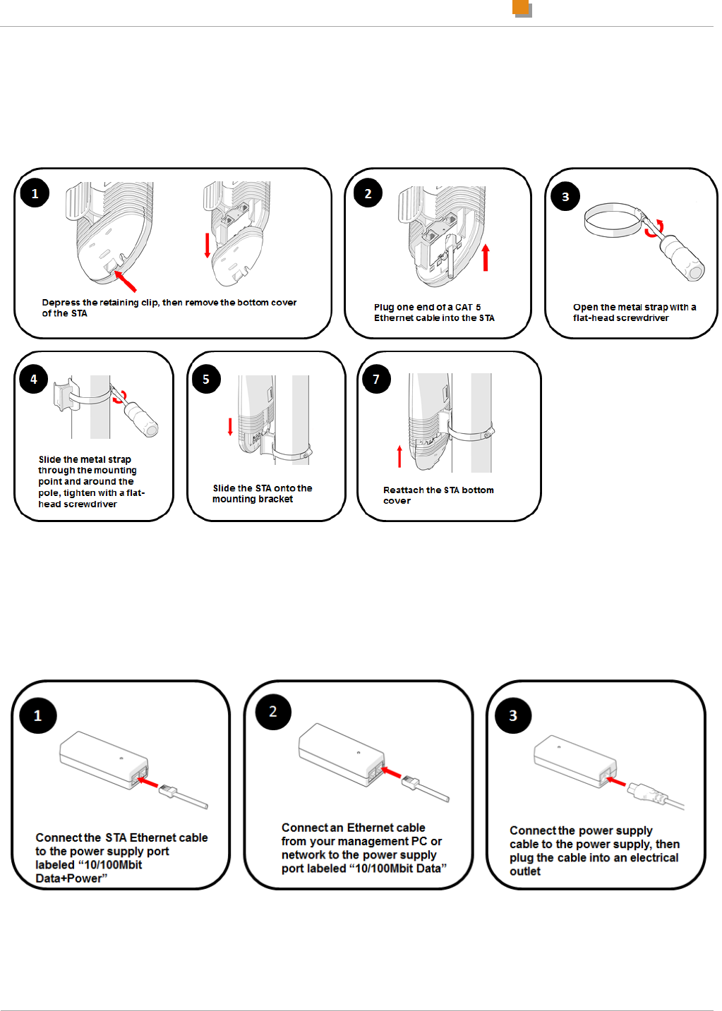
Installing the Station
The ePMP Station is designed to be pole-mounted. The Station antenna and networking components are self
contained, so an external antenna does not need to be installed.
Powering On the Station
To power on the Station, perform the following steps:
Connecting to the Unit and Logging into the Web
Management Interface
ePMP Quick Start Guide
4
pmp-0364 000v006 (July 2013)
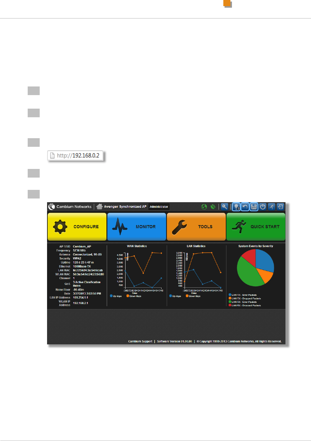
Connecting to the Unit and Logging into the Web
Management Interface
To configure or monitor your ePMP networking equipment, log into the web management interface
following the steps below:
1
Connect management PC Ethernet cable to power supply LAN port
2
Configure the management PC with an IP address in the 192.168.0.x subnet (for example,
192.168.0.100, subnet mask 255.255.255.0). This address must not be 192.168.0.1 or
192.168.0.2.
3
In your web browser, navigate to http://192.168.0.1 (AP) or http://192.168.0.2 (STA)
4
At the top of the landing page, enter username admin and password admin then click the
Login button.
5
At the home screen, click Configure, Monitor, Tools, or Quick Start to begin.
Configuring Quick Start Parameters (AP)
ePMP Quick Start Guide
5
pmp-0364 000v006 (July 2013)
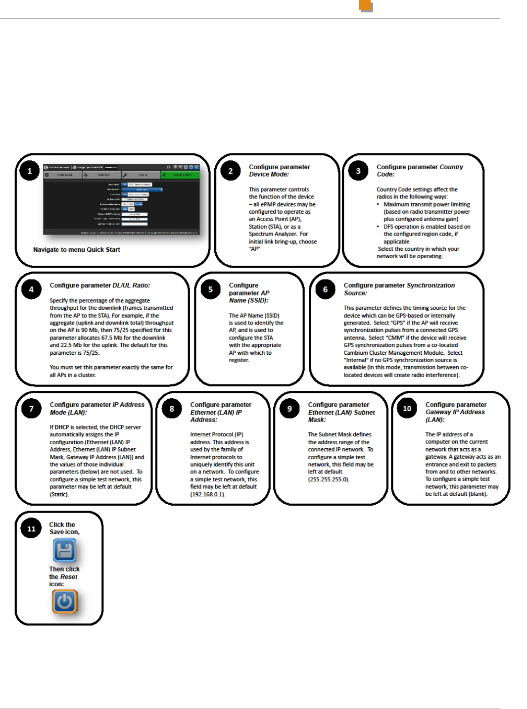
Configuring Quick Start Parameters (AP)
The Quick Start tab contains a simple listing of parameters required to configure a simple radio link and to
configure requisite networking parameters. After configuring these parameters on the AP and STA and resetting
both devices, the STA will be ready to associate (register) to the AP.
Configuring Quick Start Parameters (STA)
ePMP Quick Start Guide
6
pmp-0364 000v006 (July 2013)
Configuring Quick Start Parameters (STA)
The Quick Start tab contains a simple listing of parameters required to configure a simple radio link and
to configure requisite networking parameters.
Enabling GPS Synchronization
ePMP Quick Start Guide
7
pmp-0364 000v006 (July 2013)
Verifying Radio Connectivity
Enabling GPS Synchronization
There are two ways in which the AP may receive GPS synchronization signaling:
Internal GPS (models C024900A011A, C050900A011A, C058900A112A): The ePMP access point
contains an internal GPS chip and antenna for receiving synchronization pulse and data (location,
date, and time) from GPS satellites. For supported models, this mode may be enabled by navigating
to Configure, System and setting Synchronization Source to GPS.
Cluster Management Module (CMM): The ePMP access point may be configured to receive GPS
synchronization pulses via a co-located CMM. The access point receives synchronization over the
Ethernet cable connected to the CMM. This mode may be enabled by navigating to Configure,
System and setting Synchronization Source to CMM.
The AP web management interface contains an icon in the status bar which indicates receipt of a valid
GPS signal:
The AP is not receiving a valid synchronization pulse.
Check GPS antenna installation, cabling, or CMM configuration.
The AP is receiving a valid synchronization pulse.
All GPS-synchronized APs within radio range are transmitting and receiving at the same time.

Regulatory Compliance
ePMP Quick Start Guide
1
pmp-0364 000v006 (July 2013)
Cabling and ligntning protection
The following practices are essential to the reliability and longevity of cabled connections:
Use only shielded cables and connectors to resist interference and corrosion.
For vertical runs, provide cable support and strain relief.
Include a 2-ft (0.6-m) service loop on each end of the cable to allow for thermal expansion and
contraction and to facilitate terminating the cable again when needed.
Include a drip loop to shed water so that most of the water does not reach the connector at the
device.
Properly crimp all connectors.
Use dielectric grease on all connectors to resist corrosion.
The AP or STA must be positioned
with hardware that the wind and ambient vibrations cannot flex or move.
where a grounding system is available.
with lightning arrestors to transport lightning strikes away from equipment.
at a proper height:
o higher than the tallest points of objects immediately around them (such as trees, buildings, and
tower legs).
o at least 2 feet (0.6 meters) below the tallest point on the tower, pole, or roof (for lightning
protection).
away from high-RF energy sites (such as AM or FM stations, high-powered antennas, and live AM
radio towers).
that will not be obstructed by trees as they grow or structures that are later built.
Regulatory Compliance
The Cambium ePMP product is certified as an unlicensed device in frequency bands where it is not
allowed to cause interference to licensed services (called primary users of the bands).
Radar avoidance
In countries where radar systems are the primary band users, the regulators have mandated special
requirements to protect these systems from interference caused by unlicensed devices. Unlicensed
devices must detect and avoid co-channel operation with radar systems.
The Cambium ePMP product provides detect-and-avoid functionality for countries and frequency bands
requiring protection for radar systems.
Installers and users must meet all local regulatory requirements for radar detection. To meet these
requirements, users must set the correct country code during commissioning of the the ePMP product. If
this is not done, installers and users may be liable to civil and criminal penalties.
Contact the Cambium helpdesk if more guidance is required.

ePMP regulatory compliance
ePMP Quick Start Guide
2
pmp-0364 000v006 (July 2013)
USA and Canada specific information
The USA Federal Communications Commission (FCC) has asked manufacturers to implement special
features to prevent interference to weather radar systems that operate in the band 5600 MHz to 5650
MHz. These features must be implemented in all products able to operate outdoors in the band 5470
MHz to 5725 MHz.
Manufacturers must ensure that such radio products cannot be configured to operate outside of FCC
rules; specifically it must not be possible to disable or modify the radar protection functions that have
been demonstrated to the FCC.
In order to comply with these FCC requirements, Cambium supplies variants of the ePMP product for
operation in the USA or Canada. These variants are only allowed to operate in accordance with FCC/IC
rules. In particular, operation of radio channels overlapping the band 5600-5650 MHz is not allowed and
these channels are permanently barred.
In addition, other channels may also need to be barred when operating close to weather radar
installations. To ensure compliance with FCC rules (KDB 443999: Interim Plans to Approve UNII Devices
Operating in the 5470 - 5725 MHz Band with Radar Detection and DFS Capabilities), follow the
instructions in Avoidance of weather radars on page 5.
Other variants of the ePMP product are available for use in the rest of the world, but these variants are
not supplied to the USA or Canada except under strict controls, when they are needed for export and
deployment outside the USA or Canada.
ePMP regulatory compliance
The ePMP complies with the regulations that are enforced in the USA and Canada. The relevant
notifications are specified in this section.
ePMP FCC and IC notification
U.S. Federal Communication Commission (FCC) and Industry Canada (IC) Notification.
This system has achieved Type Approval in various countries around the world. This means that the
system has been tested against various local technical regulations and found to comply. The frequency
band in which the system operates is ‘license exempt’ and the system is allowed to be used provided it
does not cause interference. The licensing authority does not guarantee protection against interference
from other products and installations.
This device complies with part 15 of the US FCC Rules and Regulations and with RSS-210 of Industry
Canada. Operation is subject to the following two conditions: (1) This device may not cause harmful
interference, and (2) This device must accept any interference received, including interference that may
cause undesired operation. In Canada, users should be cautioned to take note that high power radars
are allocated as primary users (meaning they have priority) of the 5650 – 5850 MHz spectrum and these
radars could cause interference and/or damage to license-exempt local area networks (LELAN).

ePMP regulatory compliance
ePMP Quick Start Guide
3
pmp-0364 000v006 (July 2013)
Le présent appareil est conforme aux CNR d'Industrie Canada applicables aux appareils radio exempts
de licence. L'exploitation est autorisée aux deux conditions suivantes : (1) l'appareil ne doit pas produire
de brouillage, et (2) l'utilisateur de l'appareil doit accepter tout brouillage radioélectrique subi, même si le
brouillage est susceptible d'en compromettre le fonctionnement.
Under Industry Canada regulations, this radio transmitter may only operate using an antenna of a type
and maximum (or lesser) gain approved for the transmitter by Industry Canada. To reduce potential radio
interference to other users, the antenna type and its gain should be so chosen that the equivalent
isotropically radiated power (EIRP) is not more than that necessary for successful communication.
Conformément à la réglementation d'Industrie Canada, le présent émetteur radio peut fonctionner avec
une antenne d'un type et d'un gain maximal (ou inférieur) approuvé pour l'émetteur par Industrie Canada.
Dans le but de réduire les risques de brouillage radioélectrique à l'intention des autres utilisateurs, il faut
choisir le type d'antenne et son gain de sorte que la puissance isotrope rayonnée équivalente (PIRE) ne
dépasse pas l'intensité nécessaire à l'établissement d'une communication satisfaisante.
This equipment has been tested and found to comply with the limits for a Class B digital device, pursuant
to Part 15 of the US FCC Rules and with RSS-210 of Industry Canada. These limits are designed to
provide reasonable protection against harmful interference in a residential installation. This equipment
generates, uses, and can radiate radio-frequency energy and, if not installed and used in accordance
with these instructions, may cause harmful interference to radio communications. If this equipment does
cause harmful interference to radio or television reception, which can be determined by turning the
equipment on and off, the user is encouraged to correct the interference by one or more of the following
measures:
Increase the separation between the affected equipment and the unit;
Connect the affected equipment to a power outlet on a different circuit from that which the receiver is
connected to;
Consult the dealer and/or experienced radio/TV technician for help.
Where necessary, the end user is responsible for obtaining any National licenses required to operate this
product and these must be obtained before using the product in any particular country. Contact the
appropriate national administrations for details on the conditions of use for the bands in question and any
exceptions that might apply.
This radio transmitter (identify the device by certification number, or model number if Category II) has
been approved by Industry Canada to operate with the antenna types listed below with the maximum
permissible gain and required antenna impedance for each antenna type indicated. Antenna types not
included in this list, having a gain greater than the maximum gain indicated for that type, are strictly
prohibited for use with this device.
Le présent émetteur radio (identifier le dispositif par son numéro de certification ou son numéro de
modèle s'il fait partie du matériel de catégorie I) a été approuvé par Industrie Canada pour fonctionner
avec les types d'antenne énumérés ci-dessous et ayant un gain admissible maximal et l'impédance
requise pour chaque type d'antenne. Les types d'antenne non inclus dans cette liste, ou dont le gain est
supérieur au gain maximal indiqué, sont strictement interdits pour l'exploitation de l'émetteur.

ePMP regulatory compliance
ePMP Quick Start Guide
4
pmp-0364 000v006 (July 2013)
Approved Antenna Model
Description
Input Impedance
C050900D003A
5 GHz Antenna for 90 Degree
Sector, 17 dBi
50 Ω
C050900D003A
5 GHz Antenna for 60 Degree
Sector, 16 dBi
50 Ω
FCC ID
Industry
Canada
Cert
Number
Frequencies
Module
Families
Antenna
Maximum
Combined
Tx Output
Power1
Z8H89FT0006
109W-0006
20 MHz channels,
centered on 5735-5840
in 5 MHz increments
(within the 5725-5850
MHz ISM band)
ePMP AP 5
GHz
17 dBi
Connectorized
19 dBm
16 dBi
Connectorized
20 dBm
20 MHz channels,
centered on 5480 –
5590; 5660 – 5715 in 5
MHz increments (within
the 5470 – 5600; 5650
– 5725 MHz UNII band)
17 dBi
Connectorized
13 dBm
16 dBi
Connectorized
14 dBm
Z8H89FT0005
109W-0005
20 MHz channels,
centered on 5735-5840
in 5 MHz increments
(within the 5725-5850
MHz ISM band)
ePMP STA
5 GHz
16 dBi
Integrated
20 dBm
20 MHz channels,
centered on 5480 –
5590; 5660 – 5715 in 5
MHz increments (within
the 5470 – 5600; 5650
– 5725 MHz UNII band)
1 At band edges, transmit power must be reduced by 3 dB

Specifications
ePMP Quick Start Guide
5
pmp-0364 000v006 (July 2013)
Specific expertise and training required for professional
installers
To ensure that the ePMP equipment is installed and configured in compliance with the requirements of
Industry Canada and the FCC, installers must have the radio engineering skills and training described in
this section. This is particularly important when installing and configuring a ePMP system for operation in
the 5.4 GHz UNII band.
Avoidance of weather radars
The installer must be familiar with the requirements in FCC KDB 443999. Essentially, the installer must
be able to:
Access the FCC data base of weather radar location and channel frequencies.
Use this information to correctly configure the product (using the GUI) to avoid operation on channels
that should be barred according to the guidelines that are contained in the KDB and explained in
detail in this user guide.
External antennas
When using a connectorized version of the product (as compared to the version with an integrated
antenna), the conducted transmit power must be reduced to ensure the regulatory limit on transmitter
EIRP is not exceeded. The installer must have an understanding of how to compute the effective antenna
gain from the actual antenna gain and the feeder cable losses.
The range of permissible values for maximum antenna gain and feeder cable losses are included in the
user guide together with a sample calculation. The product GUI automatically applies the correct
conducted power limit to ensure that it is not possible for the installation to exceed the EIRP limit, when
the appropriate values for antenna gain and feeder cable losses are entered into the GUI.
Ethernet networking skills
The installer must have the ability to configure IP addressing on a PC and to set up and control products
using a web browser interface.
Lightning protection
To protect outdoor radio installations from the impact of lightning strikes, the installer must be familiar
with the normal procedures for site selection, bonding and grounding,
Specifications
Access Point (AP)

Specifications
ePMP Quick Start Guide
6
pmp-0364 000v006 (July 2013)
Category
Specification
Product
Model Number
C050900P011A, C058900P112A
Spectrum
Channel Spacing
Configurable on 5 MHz increments
Frequency
Range
5.0
GHz
5.250 GHz – 5.350 GHz, 5.470 GHz – 5.875 GHz (dependent upon
Region Code setting)
Channel Width
20 MHz
Interface
MAC (Media Access
Control) Layer
Cambium Networks Proprietary
Physical Layer
2x2 MIMO OFDM
Ethernet Interface
10/100/1000BaseT, half/full duplex, rate auto negotiated (802.3 compliant)
Protocols Used
IPv4, UDP, TCP, IP, ICMP, SNMP, HTTP, FTP
Network
Management
HTTP, SNMP v2c, Syslog
Performance

Specifications
ePMP Quick Start Guide
7
pmp-0364 000v006 (July 2013)
Category
Specification
Nominal Receive
Sensitivity (w/ FEC)
@ 20 MHz Channel,
Per Port
MCS
Rx Sensitivity at 1% PER
(dBm)
Rx Sensitivity at
10% PER (dBm)
MCS15
-68
-69
MCS14
-69
-70
MCS13
-71
-72
MCS12
-76
-77
MCS11
-79
-80
MCS10
-82
-83
MCS 9
-85
-86
MCS7
-70
-71
MCS6
-72
-73
MCS5
-73
-75
MCS4
-78
-79
MCS3
-81
-82
MCS2
-85
-86
MCS1
-88
-89
Maximum
Deployment Range
Up to 40 km (25 mi)
Subscribers Per
Sector
120
ARQ
Yes
Cyclic Prefix
1/16
Modulation Levels
(Adaptive)
MCS1 through MCS15
Latency (Round-trip)
15 ms
Packets Per Second
30,000
GPS
Synchronization
Yes, via CMM3, CMM4, or internal GPS (models C050900A011A,
C058900A112A, C024900A011A)
Quality of Service
Diffserv QoS
Link Budget

Specifications
ePMP Quick Start Guide
8
pmp-0364 000v006 (July 2013)
Category
Specification
Antenna Beam
Width
90º or 120º sectors, or Omni
Transmit Power, per
Chain
0 to +27 dBm (to EIRP limit by region) in 1 dB-configurable intervals
Antenna Gain
17 dBi Horizontal and Vertical
Physical
Wind Loading
190 km/hour (118 mi/hour)
Antenna Connection
50 ohm, SMA
Environmental
IP54
Temperature
-30ºC to +55ºC (-22ºF to +131ºF)
Weight
.521 kg (1.15 lbs) without antenna
1.92 kg (4.23 lbs) with antenna
Dimensions (H x W x
D)
Radio: 227 x 88 x 33 mm (8.9” x 3.5” x 1.3”)
Antenna: 529 x 124 x 53 mm (20.8” x 4.9” x 2.1”)
Maximum Power
Consumption
15 W over 100 meter CAT-5 Ethernet cable
Input Voltage
29 V
Security
Encryption
AES
Certifications
FCC ID
Z8H89FT0006
Industry Canada
Cert
109W-0006

Specifications
ePMP Quick Start Guide
9
pmp-0364 000v006 (July 2013)
Station (STA)
Category
Specification
Product
Model Number
C050900P031A, C058900P132A
Spectrum
Channel Spacing
Configurable on 5 MHz increments
Frequency
Range
5.0
GHz
5.250 GHz – 5.350 GHz, 5.470 GHz – 5.875 GHz (dependent upon Region
Code setting)
Channel Width
20 MHz
Interface
MAC (Media Access
Control) Layer
Cambium Networks Proprietary
Physical Layer
2x2 MIMO OFDM
Ethernet Interface
10/100BaseT, half/full duplex, rate auto negotiated (802.3 compliant)
Protocols Used
IPv4, UDP, TCP, IP, SNMP, HTTP, FTP
Network
Management
HTTP, SNMP v2c
Performance

Specifications
ePMP Quick Start Guide
10
pmp-0364 000v006 (July 2013)
Category
Specification
Nominal Receive
Sensitivity (w/ FEC)
@ 20 MHz Channel,
Per Port
MCS
Rx Sensitivity at 1%
PER (dBm)
Rx Sensitivity
at 10% PER
(dBm)
MCS15
-68
-69
MCS14
-69
-70
MCS13
-71
-72
MCS12
-76
-77
MCS11
-79
-80
MCS10
-82
-83
MCS 9
-85
-86
MCS7
-70
-71
MCS6
-72
-73
MCS5
-73
-75
MCS4
-78
-79
MCS3
-81
-82
MCS2
-85
-86
MCS1
-88
-89
Maximum
Deployment Range
Up to 40 km (25 mi)
Subscribers Per
Sector
120
ARQ
Yes
Cyclic Prefix
1/16
Modulation Levels
(Adaptive)
MCS1 through MCS15
Latency (Round-trip)
15 ms
Packets Per Second
30,000
Quality of Service
Classification Rules based on Traffic Type
Link Budget
Antenna Beam
Width
90º or 120º sectors, or Omni

Specifications
ePMP Quick Start Guide
11
pmp-0364 000v006 (July 2013)
Category
Specification
Transmit Power, per
Chain
0 to +27 dBm (to EIRP limit by region) in 1 dB-configurable intervals
Antenna Gain
16 dBi Horizontal and Vertical
Physical
Wind Loading
190 km/hour (118 mi/hour)
Antenna Connection
50 ohm, SMA
Environmental
IP54
Temperature
-30ºC to +55ºC (-22ºF to +131ºF)
Weight
4.94 kg (10.9 lbs)
Dimensions (H x W x
D)
Radio: 252 x 117 x 78 mm (9.9” x 4.6” x 3.1”)
Maximum Power
Consumption
15 W over 100 meter CAT-5 Ethernet cable
Input Voltage
29 V
Security
Encryption
AES
Certifications
FCC ID
Z8H89FT0005
Industry Canada
Cert
109W-0005

Important safety information
ePMP Quick Start Guide
12
pmp-0364 000v006 (July 2013)
Safety Notices
This section describes important safety and regulatory guidelines that must be observed by personnel
installing or operating ePMP equipment.
Important safety information
To prevent loss of life or physical injury, observe the safety guidelines in this section.
Power lines
Exercise extreme care when working near power lines.
Working at heights
Exercise extreme care when working at heights.
Grounding and protective earth
ePMP units must be properly grounded to protect against lightning. It is the user’s responsibility to install
the equipment in accordance with national regulations. In the USA, follow Section 810 of the National
Electric Code, ANSI/NFPA No.70-1984 (USA). In Canada, follow Section 54 of the Canadian Electrical
Code. These codes describe correct installation procedures for grounding the outdoor unit, mast, lead-in
wire and discharge unit, size of grounding conductors and connection requirements for grounding
electrodes. Other regulations may apply in different countries and therefore it is recommended that
installation of the outdoor unit be contracted to a professional installer.
Powering down before servicing
Always power down and unplug the equipment before servicing.
Primary disconnect device
The AP or STA unit’s power supply is the primary disconnect device.
External cables
Safety may be compromised if outdoor rated cables are not used for connections that will be exposed to
the outdoor environment.
RF exposure near the antenna
Radio frequency (RF) fields will be present close to the antenna when the transmitter is on. Always turn
off the power to the ePMP unit before undertaking maintenance activities in front of the antenna.

ePMP Quick Start Guide
13
pmp-0364 000v006 (July 2013)
Minimum separation distances
Install the AP/STA so as to provide and maintain the minimum separation distances from all persons.
The minimum separation distances for each frequency variant are specified in the ePMP User Guide.
Freq.
Band
Antenna
Variable
d
Recommended
Separation
Distance
Power
Compliance
Margin
P
G
S
5 GHz
OFDM
Integrated
STA, 16 dBi
patch
0.199 W
(23
dBm)
39.8
(16
dB)
10
W/m2
or 1
mW/c
m2
25.1
cm
26cm
Connectorize
d AP, with 17
dBi Sector
Antenna and
1dB cable
Loss
0.100 W
(20
dBm)
39.8
(16
dB)
10
W/m2
or 1
mW/c
m2
17.8
cm
20cm
Warranty
Cambium’s standard hardware warranty is for one (1) year from date of shipment from Cambium or a
Cambium Point-To-Point Distributor. Cambium warrants that hardware will conform to the relevant
published specifications and will be free from material defects in material and workmanship under normal
use and service. Cambium shall within this time, at its own option, either repair or replace the defective
product within thirty (30) days of receipt of the defective product. Repaired or replaced product will be
subject to the original warranty period but not less than thirty (30) days.

/
ePMP Quick Start Guide
14
pmp-0364 000v006 (July 2013)
Cambium Networks
Cambium Networks provides professional grade fixed wireless broadband and microwave solutions for
customers around the world. Our solutions are deployed in thousands of networks in over 153 countries,
with our innovative technologies providing reliable, secure, cost-effective connectivity that’s easy to
deploy and proven to deliver outstanding metrics.
Our flexible Point-to-Multipoint (PMP) solutions operate in the licensed, unlicensed and federal frequency
bands, providing reliable, secure, cost effective access networks. With more than three million modules
deployed in networks around the world, our PMP access network solutions prove themselves day-in and
day-out in residential access, leased line replacement, video surveillance and smart grid infrastructure
applications.
Our award-winning Point to Point (PTP) radio solutions operate in licensed, unlicensed and defined use
frequency bands including specific FIPS 140-2 solutions for the U.S. Federal market. Ruggedized for
99.999% availability, our PTP solutions have an impeccable track record for delivering reliable high-
speed backhaul connectivity even in the most challenging non-line-of-sight RF environments.
Cambium Networks solutions are proven, respected leaders in the wireless broadband industry. We
design, deploy and deliver innovative data, voice and video connectivity solutions that enable and ensure
the communications of life, empowering personal, commercial and community growth virtually
everywhere in the world.
Contacting Cambium Networks
PMP support website: http://www.cambiumnetworks.com/support
Cambium main website: http://www.cambiumnetworks.com/
Sales enquiries: solutions@cambiumnetworks.com
Email support: support@cambiumnetworks.com
Telephone numbers:
For full list of Cambium support telephone numbers, see:
http://www.cambiumnetworks.com/support/technical.php
Address:
Cambium Networks
3800 Golf Road, Suite 360
Rolling Meadows, IL 60008