Cambium Networks 89FT0006 ePMP Fixed Outdoor Wireless Transceiver User Manual Updated Users Manual
Cambium Networks Inc. ePMP Fixed Outdoor Wireless Transceiver Updated Users Manual
Contents
- 1. Exhibit D Users Manual per 2 1033 b3
- 2. Updated Users Manual
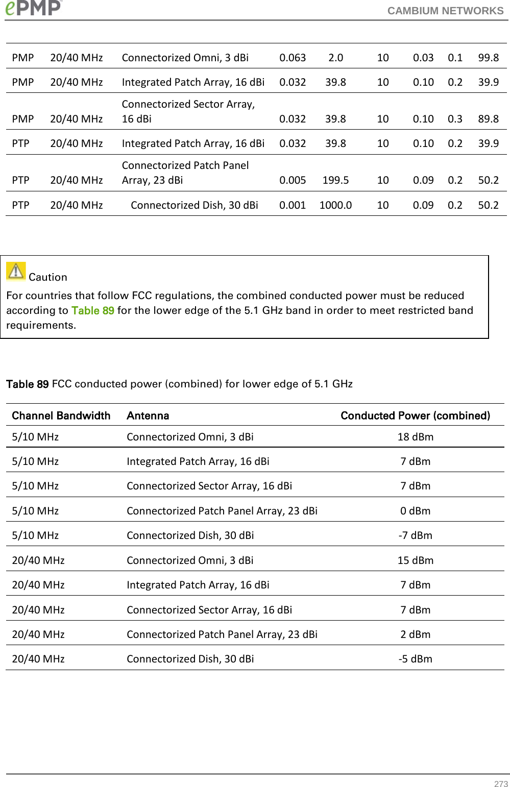
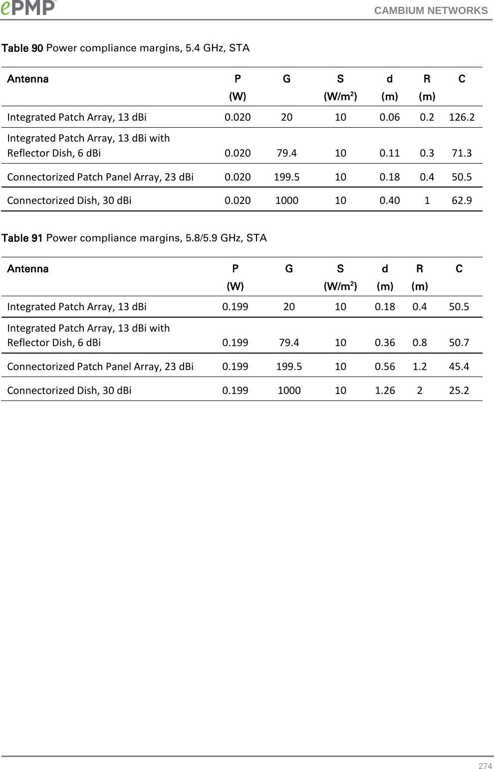
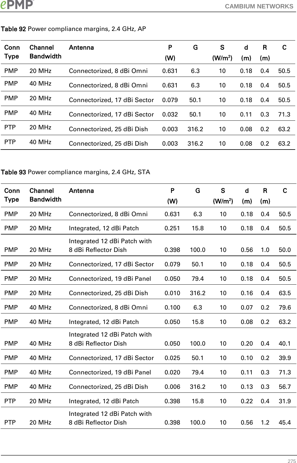
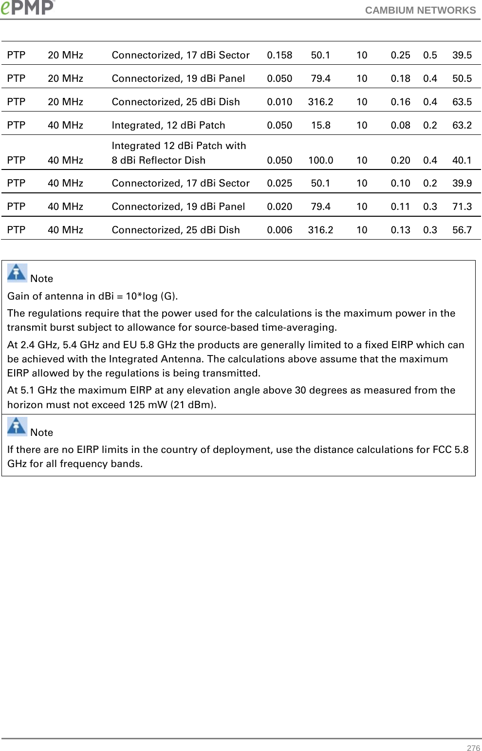
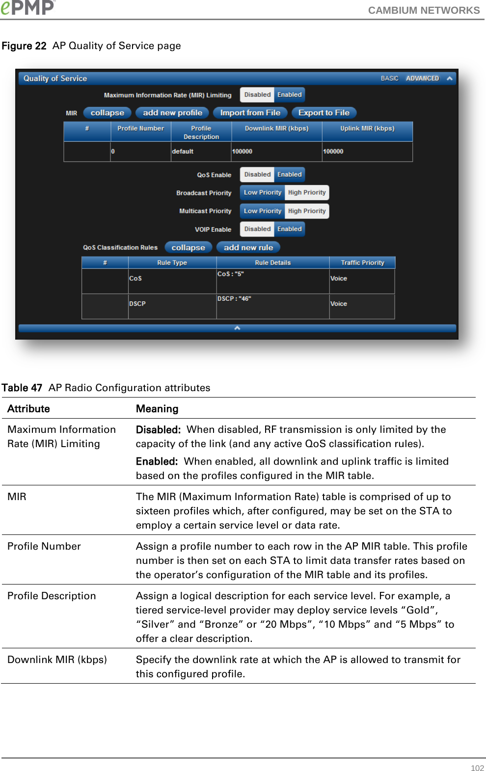
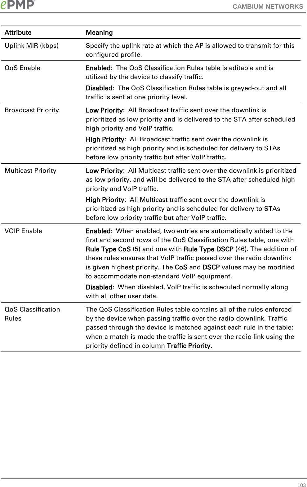
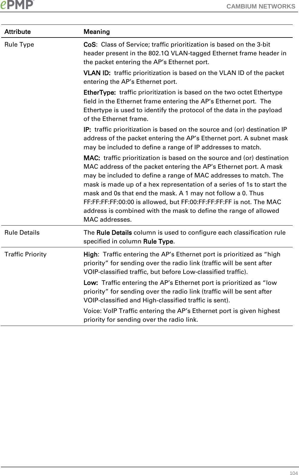
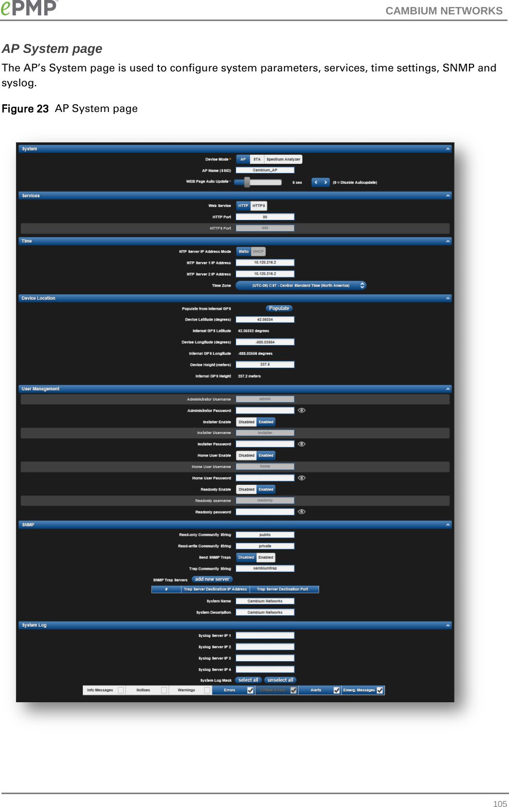
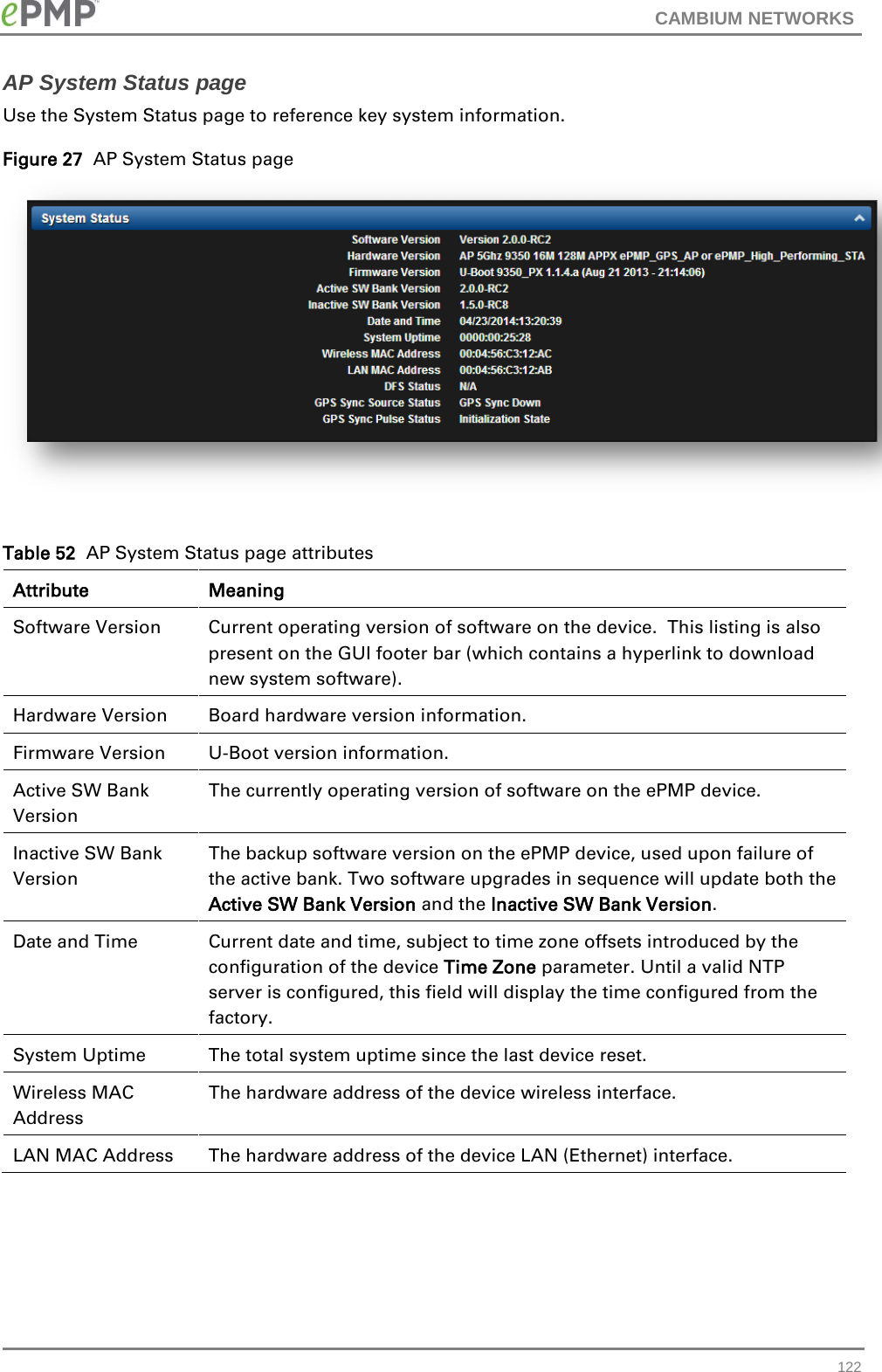
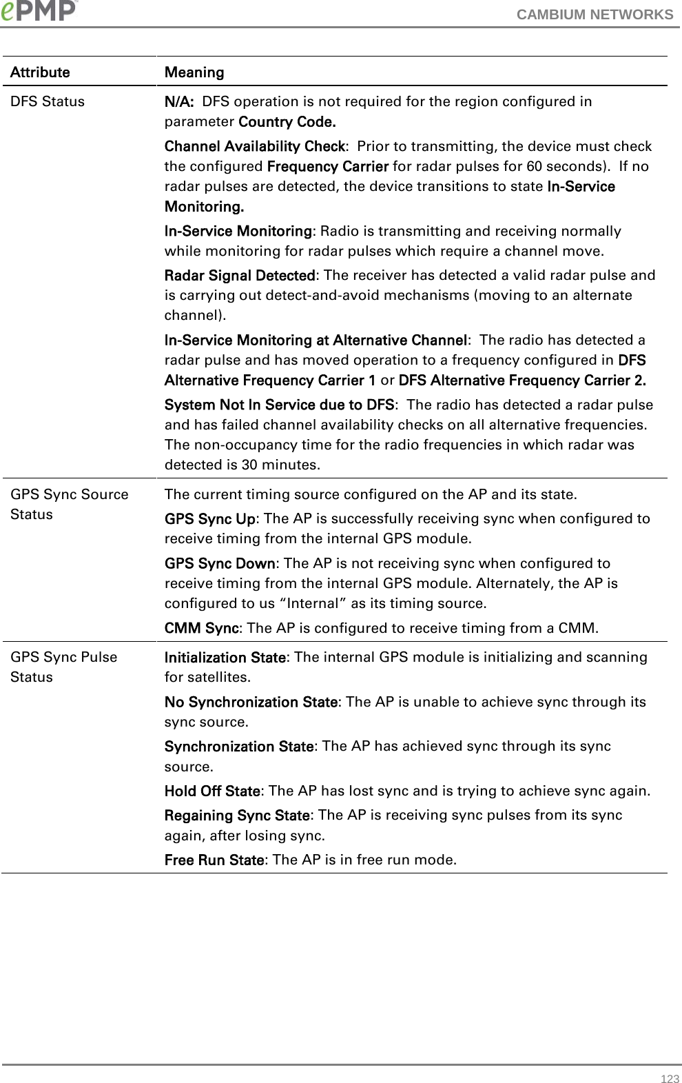
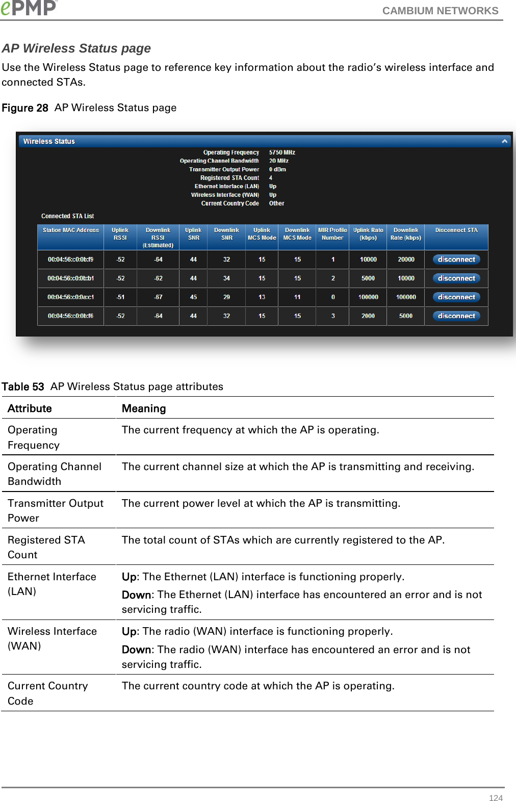
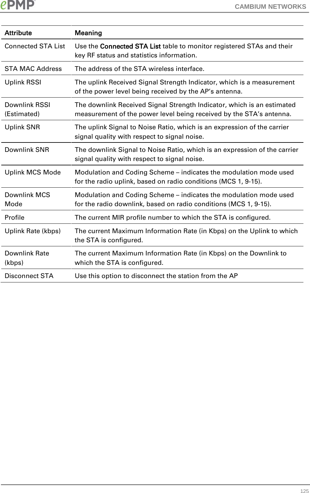
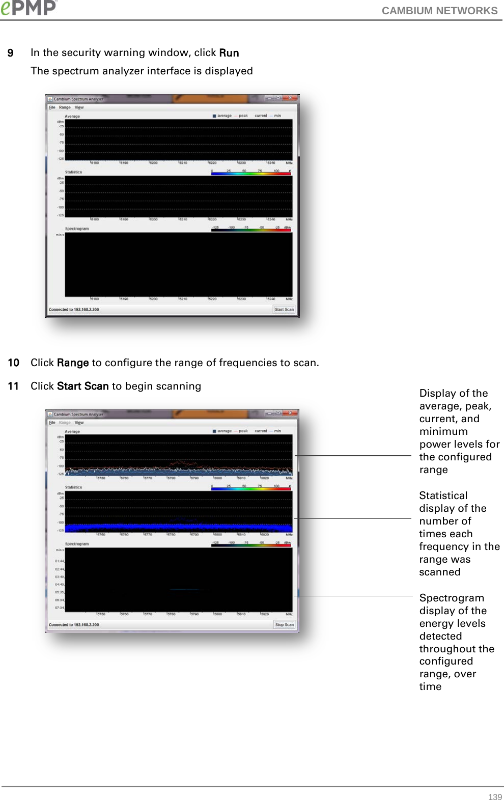
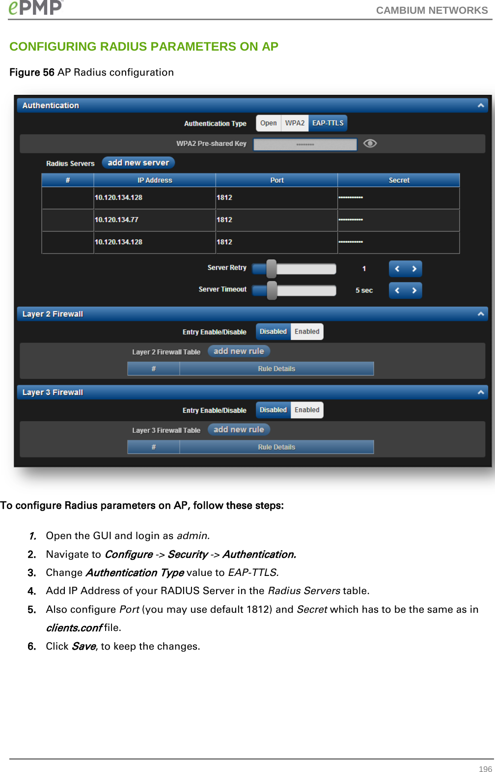
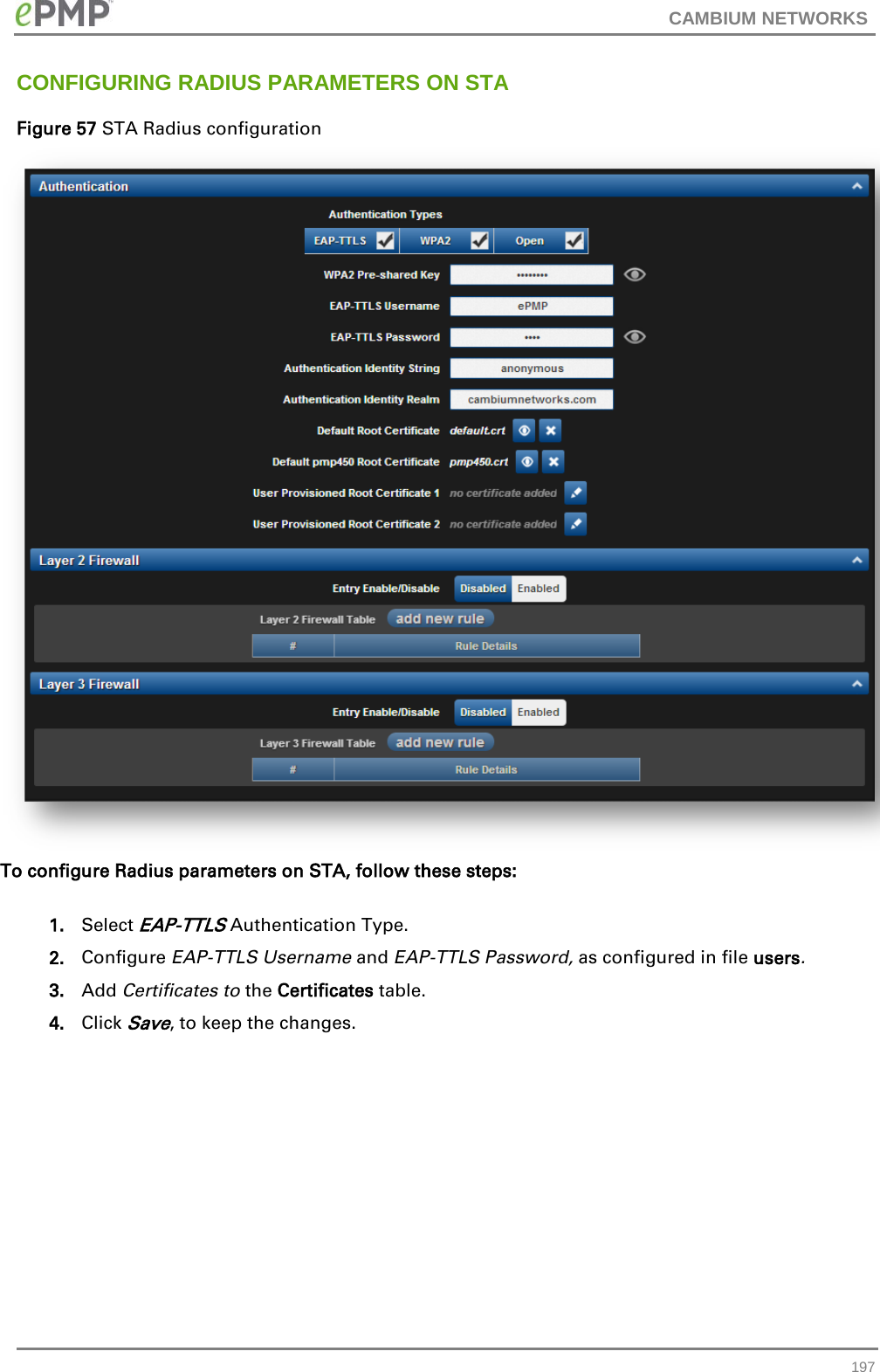
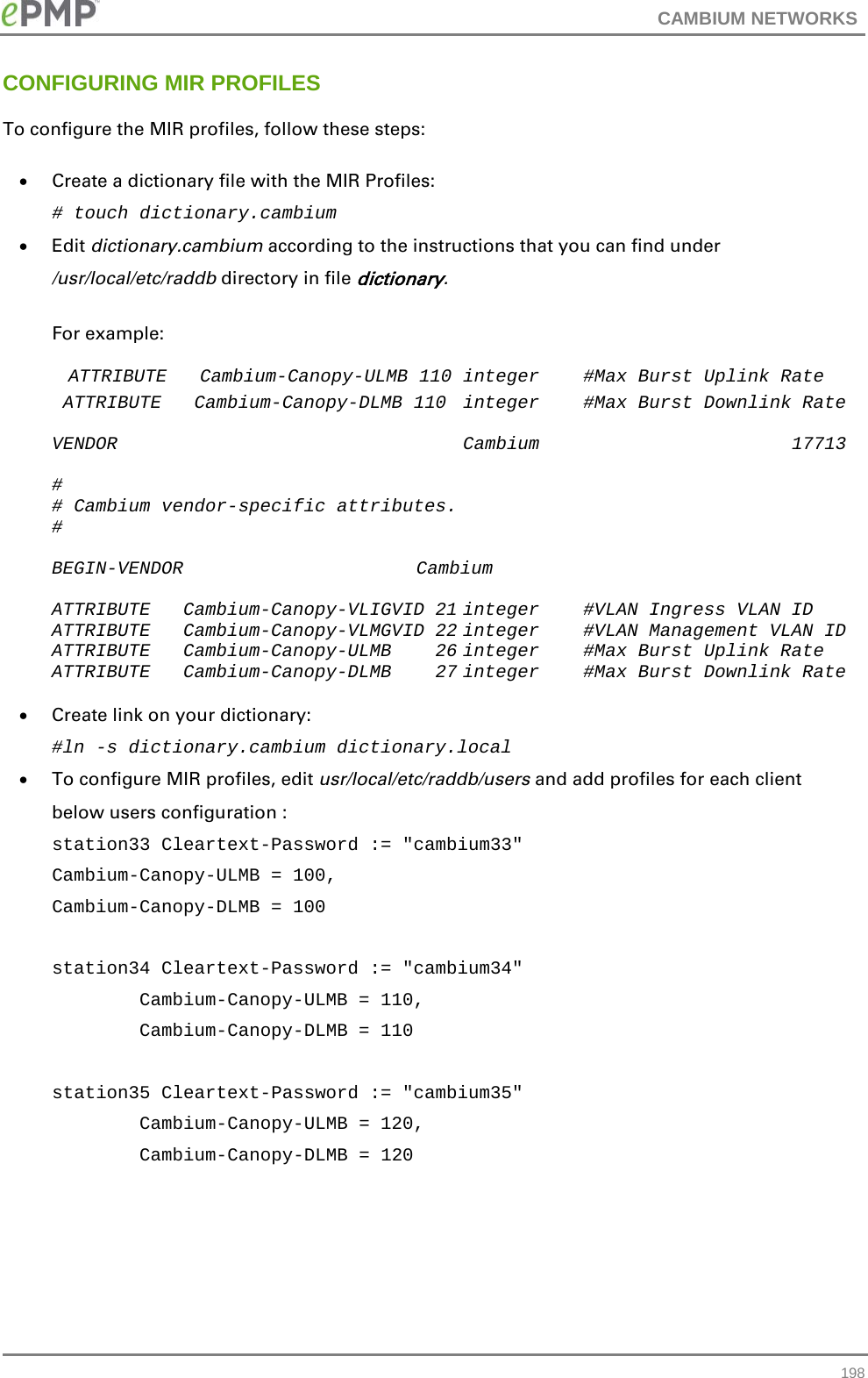
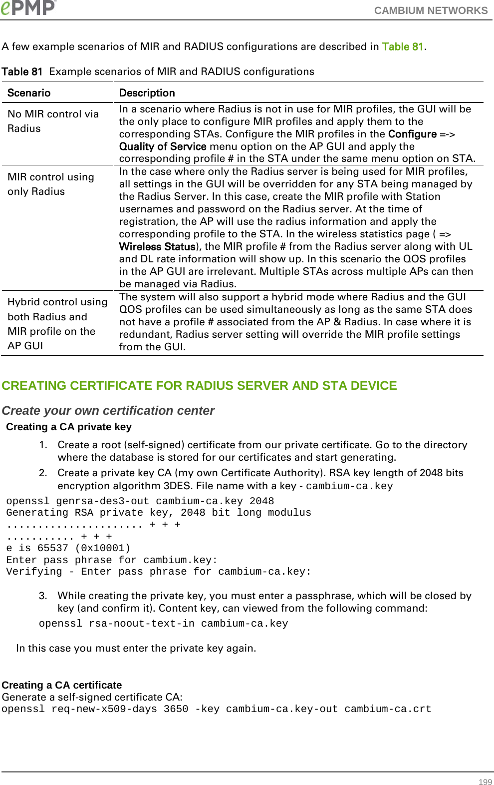
Updated Users Manual


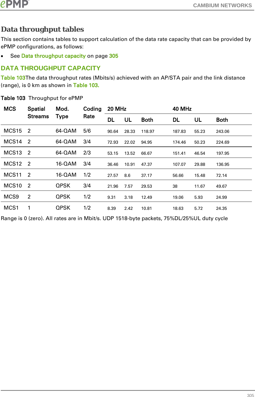
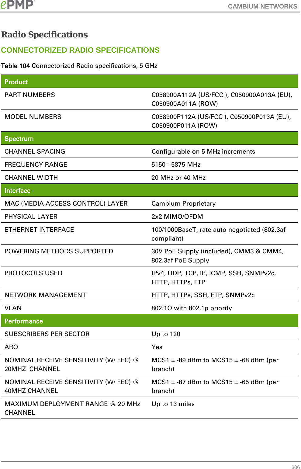
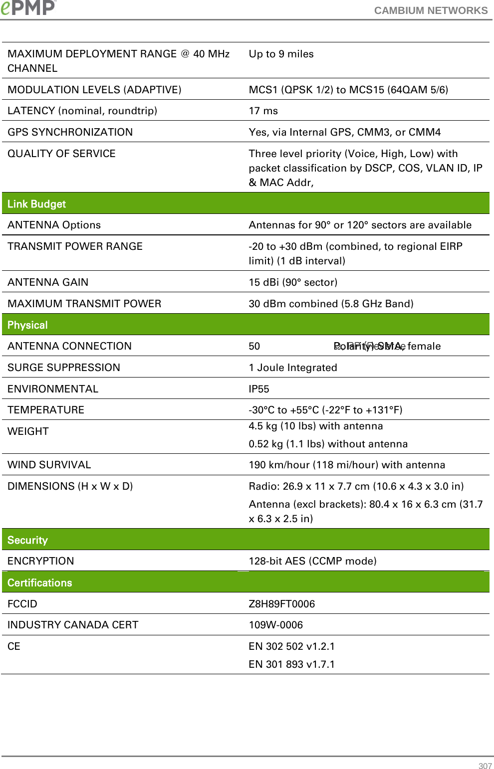
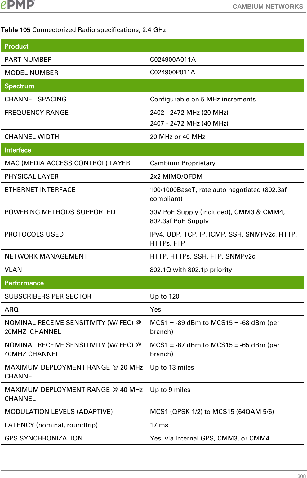
![CAMBIUM NETWORKS firewall # Copyright (C) 2009-2010 OpenWrt.org glib2 Copyright (C) 2007-2011 OpenWrt.org Copyright (C) 1994, 1995, 1996, 1997, 1998, 1999, 2000, 2001, 2002, 2003, 2004, 2005, 2006, 2007, 2008, 2009 Free Software Foundation, Inc. Copyright © 2004 Scott James Remnant <scott@netsplit.com>. Copyright (c) 1997-2006 University of Cambridge. Copyright © 2009 Codethink Limited Copyright (C) 2008-2010 Red Hat, Inc. Copyright (C) 2008 Hans Breuer Copyright (C) 2008, 2010 Collabora, Ltd. GNU LIBRARY GENERAL PUBLIC LICENSE Version 2, June 1991 Copyright (C) 1991 Free Software Foundation, Inc. 59 Temple Place, Suite 330, Boston, MA 02111-1307 USA Everyone is permitted to copy and distribute verbatim copies of this license document, but changing it is not allowed. [This is the first released version of the library GPL. It is numbered 2 because it goes with version 2 of the ordinary GPL.] See full license text on page 230. hostapd Copyright (c) 2002-2011, Jouni Malinen <j@w1.fi> and contributors All Rights Reserved. These programs are dual-licensed under both the GPL version 2 and BSD license (the one with advertisement clause removed). Either license may be used at your option. This package may include either wpa_supplicant, hostapd, or both. See README file respective subdirectories (wpa_supplicant/README or hostapd/README) for more details. See full license text on page 230. hotplug GNU GENERAL PUBLIC LICENSE Version 2, June 1991 See full license text on page 230. iperf Copyright 1999, 2000, 2001, 2002, 2003, 2004 The Board of Trustees of the University of Illinois All rights reserved 240](https://usermanual.wiki/Cambium-Networks/89FT0006.Updated-Users-Manual/User-Guide-2331216-Page-240.png)
![CAMBIUM NETWORKS libdbi GNU LESSER GENERAL PUBLIC LICENSE Version 2.1, February 1999 Copyright (C) 1991, 1999 Free Software Foundation, Inc. 59 Temple Place, Suite 330, Boston, MA 02111-1307 USA Everyone is permitted to copy and distribute verbatim copies of this license document, but changing it is not allowed. [This is the first released version of the Lesser GPL. It also counts as the successor of the GNU Library Public License, version 2, hence the version number 2.1.] See full license text on page 230. libiconv # Copyright (C) 1996, 1997, 1998, 1999, 2000, 2001, 2002, 2003, 2004, # 2005 Free Software Foundation, Inc. /* Copyright (C) 1992,1995-1999,2000-2002,2005-2006 Free Software Foundation, Inc. This file is part of the GNU C Library. /* Copyright (C) 1999-2001, 2003 Bruno Haible. This file is not part of the GNU LIBICONV Library. This file is put into the public domain. */ /* * Copyright (C) 1999-2001, 2005 Free Software Foundation, Inc. * This file is part of the GNU LIBICONV Library. * * The GNU LIBICONV Library is free software; you can redistribute it * and/or modify it under the terms of the GNU Library General Public * License as published by the Free Software Foundation; either version 2 * of the License, or (at your option) any later version. * * The GNU LIBICONV Library is distributed in the hope that it will be * useful, but WITHOUT ANY WARRANTY; without even the implied warranty of * MERCHANTABILITY or FITNESS FOR A PARTICULAR PURPOSE. See the GNU * Library General Public License for more details. */ /* Copyright (C) 1999-2004, 2006 Free Software Foundation, Inc. This file is part of the GNU LIBICONV Tools. This program is free software; you can redistribute it and/or modify 243](https://usermanual.wiki/Cambium-Networks/89FT0006.Updated-Users-Manual/User-Guide-2331216-Page-243.png)
![CAMBIUM NETWORKS WHETHER IN CONTRACT, STRICT LIABILITY, OR TORT (INCLUDING NEGLIGENCE OR OTHERWISE) ARISING IN ANY WAY OUT OF THE USE OF THIS SOFTWARE, EVEN IF ADVISED OF THE POSSIBILITY OF SUCH DAMAGE. * * The licence and distribution terms for any publically available version or * derivative of this code cannot be changed. i.e. this code cannot simply be * copied and put under another distribution licence * [including the GNU Public Licence.] */ opkg GNU GENERAL PUBLIC LICENSE Version 2, June 1991 Copyright (C) 1989, 1991 Free Software Foundation, Inc. 59 Temple Place, Suite 330, Boston, MA 02111-1307 USA Everyone is permitted to copy and distribute verbatim copies of this license document, but changing it is not allowed. See full license text on page 230. pcre Copyright (c) 1997-2010 University of Cambridge Release 8 of PCRE is distributed under the terms of the "BSD" licence, as specified below. The documentation for PCRE, supplied in the "doc" directory, is distributed under the same terms as the software itself. THE MAIN PCRE LIBRARY --------------------- Written by: Philip Hazel Email local part: ph10 Email domain: cam.ac.uk University of Cambridge Computing Service, Cambridge, England. Copyright (c) 1997-2010 University of Cambridge All rights reserved THE C++ WRAPPER LIBRARY ----------------------- Written by: Google Inc. Copyright (c) 2007-2010 Google Inc All rights reserved 255](https://usermanual.wiki/Cambium-Networks/89FT0006.Updated-Users-Manual/User-Guide-2331216-Page-255.png)