Cambium Networks 89FT0009 Dual Channel 3.6GHz MIMO Subscriber Module Transceiver User Manual PMP 450 Planning Guide
Cambium Networks Inc. Dual Channel 3.6GHz MIMO Subscriber Module Transceiver PMP 450 Planning Guide
Contents
- 1. Exhibit D Users Manual per 2 1033 c3
- 2. manual cbrs
Exhibit D Users Manual per 2 1033 c3


PMP 450 module essential information
Default IP Address for Management GUI Access 169.254.1.1
Default Administrator Username admin
Default Administrator Password (no password)
Software Upgrade Procedure
See “Updating the software version and using
CNUT” in the PMP 450 Configuration and User
Guide
Resetting to Factory Defaults (2 options)
1. On the radio GUI, navigate to Configuration,
Unit Settings and select Set to Factory
Defaults
OR
2. On the radio GUI, navigate to Configuration,
Unit Settings and enable and save option Set to
Factory Defaults Upon Default Plug
Detection. When the unit is powered on with a
default/override plug (see section “Acquiring the
Override Plug” in the PMP 450 Configuration
and User Guide) the radio will be returned to its
factory default settings.
ii pmp-0047 (March 2014)

Accuracy
While reasonable efforts have been made to assure the accuracy of this document, Cambium Networks assumes no
liability resulting from any inaccuracies or omissions in this document, or from use of the information obtained herein.
Cambium reserves the right to make changes to any products described herein to improve reliability, function, or design,
and reserves the right to revise this document and to make changes from time to time in content hereof with no obligation
to notify any person of revisions or changes. Cambium does not assume any liability arising out of the application or use
of any product, software, or circuit described herein; neither does it convey license under its patent rights or the rights of
others. It is possible that this publication may contain references to, or information about Cambium products (machines
and programs), programming, or services that are not announced in your country. Such references or information must not
be construed to mean that Cambium intends to announce such Cambium products, programming, or services in your
country.
Copyrights
This document, Cambium products, and 3rd Party Software products described in this document may include or describe
copyrighted Cambium and other 3rd Party supplied computer programs stored in semiconductor memories or other media.
Laws in the United States and other countries preserve for Cambium, its licensors, and other 3rd Party supplied software
certain exclusive rights for copyrighted material, including the exclusive right to copy, reproduce in any form, distribute
and make derivative works of the copyrighted material. Accordingly, any copyrighted material of Cambium, its licensors,
or the 3rd Party software supplied material contained in the Cambium products described in this document may not be
copied, reproduced, reverse engineered, distributed, merged or modified in any manner without the express written
permission of Cambium. Furthermore, the purchase of Cambium products shall not be deemed to grant either directly or
by implication, estoppel, or otherwise, any license under the copyrights, patents or patent applications of Cambium or
other 3rd Party supplied software, except for the normal non-exclusive, royalty free license to use that arises by operation
of law in the sale of a product.
Restrictions
Software and documentation are copyrighted materials. Making unauthorized copies is prohibited by law. No part of the
software or documentation may be reproduced, transmitted, transcribed, stored in a retrieval system, or translated into any
language or computer language, in any form or by any means, without prior written permission of Cambium.
License Agreements
The software described in this document is the property of Cambium and its licensors. It is furnished by express license
agreement only and may be used only in accordance with the terms of such an agreement.
High Risk Materials
Components, units, or 3rd Party products used in the product described herein are NOT fault-tolerant and are NOT
designed, manufactured, or intended for use as on-line control equipment in the following hazardous environments
requiring fail-safe controls: the operation of Nuclear Facilities, Aircraft Navigation or Aircraft Communication Systems,
Air Traffic Control, Life Support, or Weapons Systems (High Risk Activities). Cambium and its supplier(s) specifically
disclaim any expressed or implied warranty of fitness for such High Risk Activities.
© 2014 Cambium Networks, Inc. All Rights Reserved.
pmp-0047 (March 2014) iii

Safety and regulatory information
This section describes important safety and regulatory guidelines that must be observed by personnel installing or
operating PMP 450 equipment.
Important safety information
To prevent loss of life or physical injury, observe the safety guidelines in this section.
Power lines
Exercise extreme care when working near power lines.
Working at heights
Exercise extreme care when working at heights.
Grounding and protective earth
PMP 450 units must be properly grounded to protect against lightning. It is the user’s responsibility to install the
equipment in accordance with national regulations. In the USA, follow Section 810 of the National Electric Code,
ANSI/NFPA No.70-1984 (USA). In Canada, follow Section 54 of the Canadian Electrical Code. These codes
describe correct installation procedures for grounding the outdoor unit, mast, lead-in wire and discharge unit, size of
grounding conductors and connection requirements for grounding electrodes. Other regulations may apply in
different countries and therefore it is recommended that installation of the outdoor unit be contracted to a
professional installer.
Powering down before servicing
Always power down and unplug the equipment before servicing.
Primary disconnect device
The AP or SM unit’s power supply is the primary disconnect device.
External cables
Safety may be compromised if outdoor rated cables are not used for connections that will be exposed to the outdoor
environment.
iv pmp-0047 (March 2014)

RF exposure near the antenna
Radio frequency (RF) fields will be present close to the antenna when the transmitter is on. Always turn off the
power to the PMP 450 unit before undertaking maintenance activities in front of the antenna.
Minimum separation distances
Install the AP/SM so as to provide and maintain the minimum separation distances from all persons.
The minimum separation distances for each frequency variant are specified in Calculated distances and power
compliance margins on page 3-14.
Important regulatory information
The PMP 450 product is certified as an unlicensed device in frequency bands where it is not allowed to cause
interference to licensed services (called primary users of the bands).
Radar avoidance
In countries where radar systems are the primary band users, the regulators have mandated special requirements to
protect these systems from interference caused by unlicensed devices. Unlicensed devices must detect and avoid
co-channel operation with radar systems.
Installers and users must meet all local regulatory requirements for radar detection. To meet these requirements,
users must set the correct Country Code during commissioning of the PMP 450. If this is not done, installers and
users may be liable to civil and criminal penalties.
Contact the Cambium helpdesk if more guidance is required.
USA and Canada specific information
The USA Federal Communications Commission (FCC) has asked manufacturers to implement special features to
prevent interference to radar systems that operate in the 5250-5350 and 5470-5725 MHz bands. These features must
be implemented in all products able to operate outdoors in the UNII band. The use of the 5600 – 5650 MHz band is
prohibited, even with detect-and-avoid functionality implemented.
Manufacturers must ensure that such radio products cannot be configured to operate outside of FCC rules;
specifically it must not be possible to disable or modify the radar protection functions that have been demonstrated
to the FCC.
In order to comply with these FCC requirements, Cambium supplies variants of the PMP 450 for operation in the
USA or Canada. These variants are only allowed to operate with Country Codes that comply with FCC/IC rule.
pmp-0047 (March 2014) v

Contents PMP 450 Planning Guide
Contents
PMP 450 module essential information ...............................................................................................................................ii
Safety and regulatory information .................................................................................. iv
Important safety information ....................................................................................................................................... iv
Important regulatory information ................................................................................................................................. v
About This Planning Guide ........................................................................................... 1-4
General information ......................................................................................................................................................... 1-5
Version information .................................................................................................................................................. 1-5
Contacting Cambium Networks ............................................................................................................................... 1-5
Problems and warranty ..................................................................................................................................................... 1-7
Security advice ................................................................................................................................................................. 1-9
Warnings, cautions, and notes ........................................................................................................................................ 1-10
Overview of PMP 450 .................................................................................................................................................... 1-11
Purpose ................................................................................................................................................................... 1-11
Key features ............................................................................................................................................................ 1-11
Typical deployment ................................................................................................................................................ 1-12
System components ................................................................................................................................................ 1-13
Access Point (AP) .......................................................................................................................................................... 1-15
Network connection ................................................................................................................................................ 1-19
AP power supply .................................................................................................................................................... 1-19
Radio tab of the AP ................................................................................................................................................ 1-20
Further reading on the AP ...................................................................................................................................... 1-25
Subscriber Module (SM) ................................................................................................................................................ 1-26
Mounting brackets .................................................................................................................................................. 1-26
Network connection ................................................................................................................................................ 1-26
SM power supply .................................................................................................................................................... 1-26
Further reading on the SM ...................................................................................................................................... 1-27
Radio tab of the SM ................................................................................................................................................ 1-31
Cabling and lightning protection .................................................................................................................................... 1-36
PMP and lightning protection ................................................................................................................................. 1-36
Outdoor connections ............................................................................................................................................... 1-36
Wireless operation.......................................................................................................................................................... 1-37
Time division duplexing ......................................................................................................................................... 1-37
OFDM and channel bandwidth ............................................................................................................................... 1-37
Link operation – Dynamic Rate Adapt ................................................................................................................... 1-38
Adaptive modulation .............................................................................................................................................. 1-46
MIMO ..................................................................................................................................................................... 1-46
Cyclic Prefix ........................................................................................................................................................... 1-46
Encryption .............................................................................................................................................................. 1-46
vi pmp-0047 (March 2014)

PMP 450 Planning Guide
Further reading on wireless operation .....................................................................................................................1-46
System management .......................................................................................................................................................1-47
Management agent ..................................................................................................................................................1-47
Web server ...............................................................................................................................................................1-47
Remote Authentication Dial In User Service (RADIUS) ........................................................................................1-50
SNMP ......................................................................................................................................................................1-50
Network Time Protocol (NTP) ................................................................................................................................1-51
Wireless Manager (WM) .........................................................................................................................................1-51
Capacity upgrades ...................................................................................................................................................1-52
Software upgrade .....................................................................................................................................................1-52
Further reading on system management ..................................................................................................................1-53
Chapter 1: Planning considerations ......................................................................... 1-54
Regulatory planning ........................................................................................................................................................1-55
Obeying Regulatory limits ......................................................................................................................................1-55
Conforming to the limits .........................................................................................................................................1-55
Network migration planning ...........................................................................................................................................1-56
Example PMP 450 deployment scenario .................................................................................................................1-56
Sector capacity ........................................................................................................................................................1-58
Site planning ...................................................................................................................................................................1-65
AP or SM site selection ...........................................................................................................................................1-65
Power supply site selection .....................................................................................................................................1-65
Maximum cable lengths ..........................................................................................................................................1-65
Wind loading ...........................................................................................................................................................1-66
Link planning ..................................................................................................................................................................1-69
Range and obstacles ................................................................................................................................................1-69
Path loss considerations ...........................................................................................................................................1-92
Calculating maximum power level for connectorized AP units ..............................................................................1-92
Understanding Attenuation ......................................................................................................................................1-92
Calculating Link Loss .............................................................................................................................................1-93
Calculating Rx Signal Level ....................................................................................................................................1-93
Calculating Fade Margin .........................................................................................................................................1-94
Analyzing the RF Environment ......................................................................................................................................1-94
Mapping RF Neighbor Frequencies ........................................................................................................................1-94
Analyzing the spectrum ...........................................................................................................................................1-95
Anticipating Reflection of Radio Waves .................................................................................................................1-96
Noting Possible Obstructions in the Fresnel Zone ..................................................................................................1-96
Multiple OFDM Access Point Clusters ...................................................................................................................1-97
Planning for co-location and using the OFDM Frame Calculator Tool ..................................................................1-99
Selecting Sites for Network Elements ........................................................................................................................... 1-102
Surveying Sites ...................................................................................................................................................... 1-103
Clearing the Radio Horizon ................................................................................................................................... 1-103
Calculating the Aim Angles .................................................................................................................................. 1-104
Diagramming Network Layouts .................................................................................................................................... 1-105
Avoiding Self Interference .................................................................................................................................... 1-105
pmp-0047 (March 2014) vii

Contents PMP 450 Planning Guide
Avoiding Other Interference ................................................................................................................................. 1-106
Grounding and lightning protection ............................................................................................................................. 1-107
The need for power surge protection .................................................................................................................... 1-107
Standards .............................................................................................................................................................. 1-107
Lightning protection zones ................................................................................................................................... 1-108
General protection requirements .......................................................................................................................... 1-109
Protection requirements for a mast or tower installation ...................................................................................... 1-110
Protection requirements for a wall installation ..................................................................................................... 1-111
Protection requirements on a high rise building ................................................................................................... 1-112
Configuration options for TDD synchronization ......................................................................................................... 1-115
GPS synchronization ............................................................................................................................................ 1-116
Mounting the GPS receiver (CMM or UGPS) module on the equipment building .............................................. 1-118
Mounting the GPS receiver (CMM or UGPS) module on a metal tower or mast ................................................ 1-118
Data network planning ................................................................................................................................................. 1-119
Understanding addresses ...................................................................................................................................... 1-119
Dynamic or static addressing ................................................................................................................................ 1-119
DNS Client ........................................................................................................................................................... 1-120
Network Address Translation (NAT) ................................................................................................................... 1-120
Developing an IP addressing scheme ................................................................................................................... 1-121
Address Resolution Protocol ................................................................................................................................ 1-121
Allocating subnets ................................................................................................................................................ 1-122
Selecting non-routable IP addresses ..................................................................................................................... 1-122
Translation bridging ............................................................................................................................................. 1-123
Engineering VLANs ............................................................................................................................................. 1-123
Security planning ......................................................................................................................................................... 1-127
Isolating APs from the Internet ............................................................................................................................ 1-127
Managing module access by passwords ............................................................................................................... 1-127
Filtering protocols and ports ................................................................................................................................. 1-131
Port Lockdown ..................................................................................................................................................... 1-134
Isolating SMs ........................................................................................................................................................ 1-134
Filtering management through Ethernet ............................................................................................................... 1-135
Allowing management from only specified IP addresses ..................................................................................... 1-135
Configuring management IP by DHCP ................................................................................................................ 1-135
Planning for airlink security ................................................................................................................................. 1-136
Planning for RF Telnet Access Control ................................................................................................................ 1-136
Forwarding Downlink PPPoE PADI packets ....................................................................................................... 1-136
Planning for RADIUS integration ........................................................................................................................ 1-136
Planning for SNMP security ................................................................................................................................. 1-137
Ordering components ................................................................................................................................................... 1-138
PMP 450 component part numbers....................................................................................................................... 1-138
Chapter 2: Legal information ..................................................................................... 2-1
Cambium Networks end user license agreement ............................................................................................................. 2-2
Acceptance of this agreement ................................................................................................................................... 2-2
Definitions ................................................................................................................................................................ 2-2
viii pmp-0047 (March 2014)

PMP 450 Planning Guide
Grant of license .........................................................................................................................................................2-2
Conditions of use .......................................................................................................................................................2-2
Title and restrictions ..................................................................................................................................................2-3
Confidentiality ...........................................................................................................................................................2-4
Right to use Cambium’s name ..................................................................................................................................2-4
Transfer .....................................................................................................................................................................2-4
Updates ......................................................................................................................................................................2-4
Maintenance ..............................................................................................................................................................2-5
Disclaimer .................................................................................................................................................................2-5
Limitation of liability ................................................................................................................................................2-5
U.S. government ........................................................................................................................................................2-6
Term of license ..........................................................................................................................................................2-6
Governing law ...........................................................................................................................................................2-6
Assignment ................................................................................................................................................................2-6
Survival of provisions ...............................................................................................................................................2-6
Entire agreement ........................................................................................................................................................2-7
Third party software ..................................................................................................................................................2-7
Hardware warranty..........................................................................................................................................................2-10
Limit of liability ..............................................................................................................................................................2-11
Chapter 3: Reference information .............................................................................. 3-1
Equipment specifications ..................................................................................................................................................3-2
AP specifications .......................................................................................................................................................3-2
SM specifications ......................................................................................................................................................3-7
Wireless specifications ....................................................................................................................................................3-10
General wireless specifications ...............................................................................................................................3-10
Data network specifications ............................................................................................................................................3-11
Ethernet interface ....................................................................................................................................................3-11
Compliance with safety standards ...................................................................................................................................3-12
Electrical safety compliance ....................................................................................................................................3-12
Electromagnetic compatibility (EMC) compliance .................................................................................................3-12
Human exposure to radio frequency energy ............................................................................................................3-13
Compliance with radio regulations .................................................................................................................................3-17
Type approvals ........................................................................................................................................................3-17
DFS for 5.4 GHz Radios .........................................................................................................................................3-18
Country Codes and available spectrum ...................................................................................................................3-20
FCC compliance testing ..........................................................................................................................................3-36
FCC and ICC IDs and certification numbers ...........................................................................................................3-36
Notifications ....................................................................................................................................................................3-42
PMP 450 regulatory compliance .............................................................................................................................3-42
Appendix A: Glossary ..................................................................................................... I
pmp-0047 (March 2014) ix

List of Figures PMP 450 Planning Guide
List of Figures
Figure 1 Line Of Sight Diagram .......................................................................................................................................... 1-12
Figure 2 AP, Radio unit ....................................................................................................................................................... 1-15
Figure 3 AP, antenna ........................................................................................................................................................... 1-15
Figure 4 AP interfaces – 2.4 GHz, 3.5 GHz, 3.6GHz, 5 GHz ............................................................................................... 1-16
Figure 5 AP interfaces - 5 GHz original layout .................................................................................................................... 1-17
Figure 6 AP ground and equilibrium membrane vent ........................................................................................................... 1-18
Figure 7 AP diagnostic LEDs, viewed from front of the unit ............................................................................................... 1-18
Figure 8 Radio tab of the AP ................................................................................................................................................ 1-20
Figure 9 PMP 450 Series SM................................................................................................................................................ 1-26
Figure 10 SM interfaces ........................................................................................................................................................ 1-27
Figure 11 Connectorized SM ................................................................................................................................................ 1-28
Figure 12 SM diagnostic LEDs, viewed from front of the unit ............................................................................................ 1-29
Figure 13 Radio tab of the SM ............................................................................................................................................. 1-31
Figure 14 Custom Frequency tab of the SM ........................................................................................................................ 1-32
Figure 15 TDD Frame Division ............................................................................................................................................ 1-37
Figure 16 AP web-based management screenshot ................................................................................................................ 1-48
Figure 17 Determinants in Rx signal level ............................................................................................................................ 1-93
Figure 18 Example layout of 16 Access Point sectors (ABCD), 90 degree sectors .............................................................. 1-97
Figure 19 Example layout of 16 Access Point sectors (ABC), 60 degree sectors ................................................................. 1-98
Figure 20 OFDM Frame Calculator tab .............................................................................................................................. 1-100
Figure 21 Variables for calculating angle of elevation (and depression) ............................................................................ 1-104
Figure 22 Rolling sphere method to determine the lightning protection zones................................................................... 1-108
Figure 23 Grounding cable minimum bend radius and angle ............................................................................................. 1-109
Figure 24 Grounding and lightning protection on mast or tower ........................................................................................ 1-110
Figure 25 Grounding and lightning protection on wall ....................................................................................................... 1-111
Figure 26 Grounding and lightning protection on building ................................................................................................ 1-114
Figure 27 Grounding and lightning protection inside high building ................................................................................... 1-114
Figure 28 One unsynchronized AP in cluster resulting in self-interference ....................................................................... 1-117
Figure 29 GPS timing throughout the network ................................................................................................................... 1-117
Figure 30 Cambium network management domain ............................................................................................................ 1-120
Figure 31 Example of IP address in Class B subnet ........................................................................................................... 1-122
Figure 32 Categorical protocol filtering .............................................................................................................................. 1-133
Figure 33 AP DFS Status ...................................................................................................................................................... 3-18
x pmp-0047 (March 2014)

PMP 450 Planning Guide List of Tables
List of Tables
Table 1 PMP 450 frequency variants .....................................................................................................................................1-14
Table 2 AP interface descriptions and cabling – 2.4 GHz, 3.5 GHz, 5 GHz .........................................................................1-16
Table 3 AP interface descriptions and cabling – 5 GHz original layout ................................................................................1-17
Table 4 AP interface descriptions and cabling – ground lug .................................................................................................1-18
Table 5 AP LED descriptions ................................................................................................................................................1-19
Table 6 AP Radio attributes ..................................................................................................................................................1-21
Table 7 SM Interfaces ............................................................................................................................................................1-28
Table 8 SM diagnostic LED descriptions ..............................................................................................................................1-30
Table 9 SM Radio attributes .................................................................................................................................................1-33
Table 10 Link Budget Details – Dynamic Rate Adapt, 5.4 GHz ...........................................................................................1-39
Table 11 Link Budget Details – Dynamic Rate Adapt, 5.8 GHz ...........................................................................................1-40
Table 12 Link Budget Details – Dynamic Rate Adapt, 2.4GHz ............................................................................................1-41
Table 13 Link Budget Details – Dynamic Rate Adapt, 3.5GHz ............................................................................................1-42
Table 14 Link Budget Details – Dynamic Rate Adapt, 3.6GHz ............................................................................................1-43
Table 15 Link Budget Details – Dynamic Rate Adapt, 5.4GHz PMP 450 AP and PMP 430 SM .........................................1-44
Table 16 Link Budget Details – Dynamic Rate Adapt, 5.8GHz PMP 450 AP and PMP 430 SM .........................................1-45
Table 17 Deployment scenario terminology descriptions ......................................................................................................1-56
Table 18 Examples of aggregate sector throughput – FSK (PMP 1x0 Series) ......................................................................1-58
Table 19 Examples of aggregate sector throughput – OFDM (PMP 430 Series) ..................................................................1-58
Table 20 Examples of aggregate sector throughput – OFDM MIMO (PMP 450 Series) ......................................................1-59
Table 21 Examples of aggregate sector throughput – PMP 450 AP to PMP 430 SM ..........................................................1-60
Table 22 Deployment scenario 1 ...........................................................................................................................................1-60
Table 23 Scenario 1 spectrum usage ......................................................................................................................................1-61
Table 24 Deployment scenario 2 ...........................................................................................................................................1-63
Table 25 Deployment scenario 2 spectrum usage ..................................................................................................................1-64
Table 26 Sync cable length specification ...............................................................................................................................1-65
Table 27 Lateral force - metric ..............................................................................................................................................1-66
Table 28 Lateral force - US ...................................................................................................................................................1-67
Table 29 Link budget details – 5.8 GHz PMP 450 link, 20 MHz Channel Bandwidth .........................................................1-70
Table 30 Link budget details – 5.8 GHz PMP 450 link, 10 MHz Channel Bandwidth .........................................................1-71
Table 31 Link budget details – 5.8 GHz PMP 450 link, 5 MHz Channel Bandwidth ...........................................................1-73
Table 32 Link budget details – 5.4 GHz PMP 450 link, 20 MHz Channel Bandwidth .........................................................1-74
Table 33 Link budget details – 5.4 GHz PMP 450 link, 10 MHz Channel Bandwidth .........................................................1-75
Table 34 Link budget details – 5.4 GHz PMP 450 link, 5 MHz Channel Bandwidth ...........................................................1-76
Table 35 Link budget details – 2.4 GHz PMP 450 link, 20 MHz Channel Bandwidth .........................................................1-77
Table 36 Link budget details – 2.4 GHz PMP 450 link, 10 MHz Channel Bandwidth .........................................................1-78
Table 37 Link budget details – 2.4 GHz PMP 450 link, 5 MHz Channel Bandwidth ...........................................................1-79
Table 38 Link budget details – 3.5 GHz PMP 450 link, 20 MHz Channel Bandwidth .........................................................1-80
Table 39 Link budget details – 3.5 GHz PMP 450 link, 10 MHz Channel Bandwidth .........................................................1-81

PMP 450 Planning Guide
Table 40 Link budget details – 3.5 GHz PMP 450 link, 5 MHz Channel Bandwidth .......................................................... 1-82
Table 41 Link budget details – 3.6 GHz PMP 450 link, 20 MHz Channel Bandwidth ........................................................ 1-83
Table 42 Link budget details – 3.6 GHz PMP 450 link, 10 MHz Channel Bandwidth ........................................................ 1-84
Table 43 Link budget details – 3.6 GHz PMP 450 link, 5 MHz Channel Bandwidth .......................................................... 1-85
Table 44 Link budget details – 5.8GHz PMP 450 AP and PMP 430 SM link, 20MHz Channel Bandwidth ....................... 1-86
Table 45 Link budget details – 5.8GHz PMP 450 AP and PMP 430 SM link, 10MHz Channel Bandwidth ....................... 1-87
Table 46 Link budget details – 5.8GHz PMP 450 AP and PMP 430 SM link, 5MHz Channel Bandwidth ......................... 1-88
Table 47 Link budget details – 5.4GHz PMP 450 AP and PMP 430 SM link, 20MHz Channel Bandwidth ....................... 1-89
Table 48 Link budget details – 5.4GHz PMP 450 AP and PMP 430 SM link, 10MHz Channel Bandwidth ....................... 1-90
Table 49 Link budget details – 5.4GHz PMP 450 AP and PMP 430 SM link, 5MHz Channel Bandwidth ......................... 1-91
Table 50 Example 5.8-GHz OFDM channel assignment by sector ...................................................................................... 1-97
Table 51 Example 5.8-GHz OFDM channel assignment by sector ...................................................................................... 1-98
Table 52 OFDM Frame Calculator tab attributes ............................................................................................................... 1-100
Table 53 OFDM Calculated Frame Results attributes ........................................................................................................ 1-101
Table 54 Special case VLAN IDs ....................................................................................................................................... 1-124
Table 55 VLAN filters in point-to-multipoint modules ...................................................................................................... 1-125
Table 56 Q-in-Q Ethernet frame ......................................................................................................................................... 1-126
Table 57 Identity-based user account permissions - AP ..................................................................................................... 1-128
Table 58 Identity-based user account permissions - SM..................................................................................................... 1-130
Table 59 Ports filtered per protocol selections .................................................................................................................... 1-134
Table 60 Device default port numbers ................................................................................................................................ 1-134
Table 61 PMP 450 components .......................................................................................................................................... 1-138
Table 62 Connectorized AP physical specifications ............................................................................................................... 3-2
Table 63 SM physical specifications ...................................................................................................................................... 3-7
Table 64 PMP 450 wireless specifications ........................................................................................................................... 3-10
Table 65 PMP 450 Ethernet bridging specifications ............................................................................................................. 3-11
Table 66 PMP 450 safety compliance specifications ............................................................................................................ 3-12
Table 67 EMC emissions compliance ................................................................................................................................... 3-12
Table 68 Power Compliance Margins ................................................................................................................................... 3-15
Table 69 Radio certifications ................................................................................................................................................ 3-17
Table 70 OFDM DFS operation based on Country Code setting.......................................................................................... 3-19
Table 71 Center channel details based on Country Code, 2.4 GHz ...................................................................................... 3-21
Table 72 AP Default combined transmits power per Country Code and Lower/Upper Band Edge Path Max TX Detail, 2.4
GHz................................................................................................................................................................................ 3-22
Table 73 Center channel details based on Country Code, 3.5 GHz ..................................................................................... 3-23
Table 74 AP default combined transmit power per Country Code – 3.5 GHz band. ............................................................ 3-25
Table 75 Center channel details based on Country Code, 3.6 GHz ..................................................................................... 3-26
Table 76 AP default combined transmit power per Country Code – 3.6 GHz band ............................................................. 3-28
Table 77 Center channel details based on Country Code, 5.4 GHz ...................................................................................... 3-29
Table 78 Center channel details based on Country Code, 5.8 GHz ...................................................................................... 3-30
Table 79 Default combined transmit power per Country Code – 5.4 GHz band .................................................................. 3-31
Table 80 Default combined transmit power per Country Code – 5.8 GHz band .................................................................. 3-34
Table 81 US FCC IDs and Industry Canada Certification Numbers and Covered Configurations ...................................... 3-36
Table 82 Industry Canada approved antenna list .................................................................................................................. 3-43
Table 83 Glossary ....................................................................................................................................................................... I
1-2 pmp-0047 (March 2014)

PMP 450 Planning Guide
About This Planning Guide
This guide describes the planning of the Cambium PMP 450 Series of point-to-multipoint wireless equipment
deployment. It is intended for use by the system designer.
The guide consists of the following chapters:
• 0Product description on page 1-6
• Chapter 1: Planning considerations on page 1-54
• Chapter 2: Legal information on page 2-1
• Chapter 3: Reference information on page 3-1
1-4 pmp-0047 (March 2014)

PMP 450 Planning Guide
General information
Version information
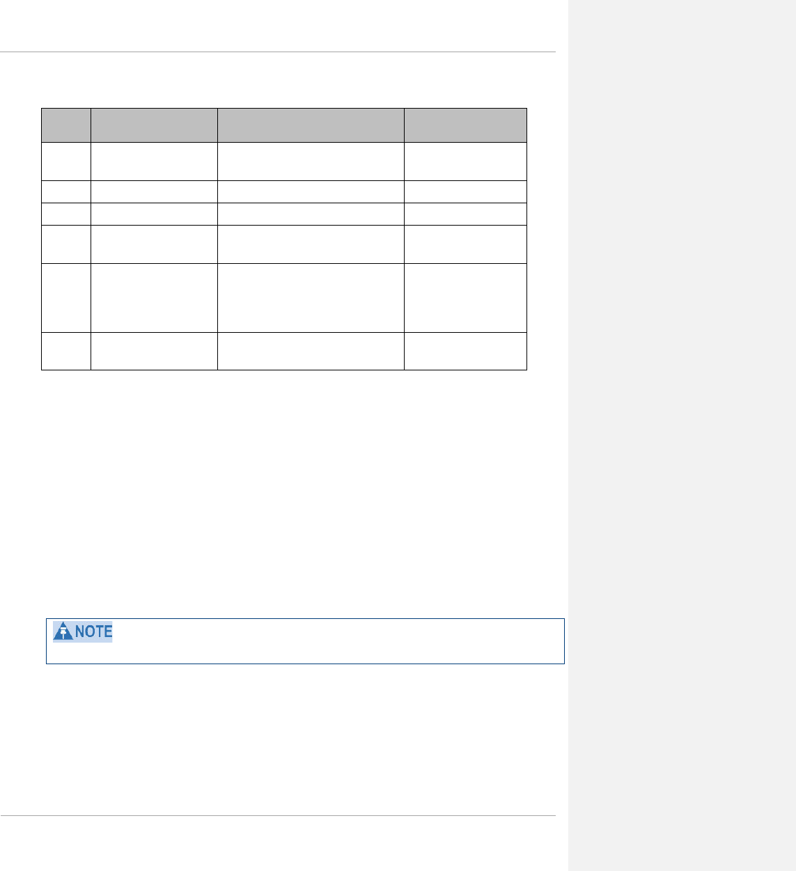
The following shows the issue status of this document since it was first released:
Issue Date of issue Remarks
001v000 September 2012 System Release 12.0
002v000 October 2012 Includes additional co-location information
003v000 November 2012 Updated for System Release 12.0.1
004v000 January 2013 Updated for System Release 12.0.2
005v000
March 2013 Updated for System Release 12.0.3/12.0.3.1
Includes additional performance details (SNR)
006v000
007v000 June 2013 Updated for System Release 12.1
008v000 September 2013 Updated for System Release 12.1.2
009v000 December 2013 Updated for System Release 12.2
010v000 February 2014 Updated for System Release 13.0
011v000 March 2014 Updated for System Release 13.1
Contacting Cambium Networks
PMP support website: http://www.cambiumnetworks.com/support
Cambium main website: http://www.cambiumnetworks.com/
Sales enquiries: sales@cambiumnetworks.com
Email support: support@cambiumnetworks.com
Telephone numbers:
For full list of Cambium support telephone numbers, see:
http://www.cambiumnetworks.com/support/contact-support
Address:
Cambium Networks
3800 Golf Road, Suite 360
Rolling Meadows, IL 60008
pmp-0047 (March 2014) 1-5

PMP 450 Planning Guide
Product description
This chapter provides a high level description of the PMP 450 product. It describes in general terms the function of
the product, the main product variants and typical deployment. It also describes the main hardware components.
The chapter consists of the following topics:
• Overview of PMP 450 on page 1-11: Introduces the key features, typical uses, product variants and
components of the PMP 450.
• Access Point (AP) on page 1-15: Describes the AP and its interfaces
• Subscriber Module (SM) on page 1-26: Describes the SM and its interfaces
• Cabling and lightning protection on page 1-36: Describes the cabling and lightning protection components of a
PMP 450 installation.
• Wireless operation on page 1-37: Describes how the PMP 450 wireless link is operated, including modulation
modes, power control and security.
• System management on page 1-47: Introduces the PMP 450 management system, including the web interface,
installation, configuration, alerts and upgrades.
Purpose
Cambium Networks Point-To-Multipoint (PMP) documents are intended to instruct and assist personnel in the
operation, installation and maintenance of the Cambium PMP equipment and ancillary devices. It is recommended
that all personnel engaged in such activities be properly trained.
Cambium disclaims all liability whatsoever, implied or express, for any risk of damage, loss or reduction in system
performance arising directly or indirectly out of the failure of the customer, or anyone acting on the customer's
behalf, to abide by the instructions, system parameters, or recommendations made in this document.
Cross references
References to external publications are shown in italics. Other cross references, emphasized in blue text in
electronic versions, are active links to the references.
This document is divided into numbered chapters that are divided into sections. Sections are not numbered, but are
individually named at the top of each page, and are listed in the table of contents.
Feedback
We appreciate feedback from the users of our documents. This includes feedback on the structure, content,
accuracy, or completeness of our documents. Send feedback to email support (see ‘Contacting Cambium
Networks’).
1-6 pmp-0047 (March 2014)

PMP 450 Planning Guide
Problems and warranty
Reporting problems
If any problems are encountered when installing or operating this equipment, follow this procedure to investigate
and report:
1 Search this document and the software release notes of supported releases.
2 Visit the support website. http://www.cambiumnetworks.com/support
3 Ask for assistance from the Cambium product supplier.
4 Gather information from affected units such as:
• The IP addresses and MAC addresses.
• The software releases.
• The configuration of software features.
• Any available diagnostic downloads.
• CNUT Support Capture Tool information
5 Escalate the problem by emailing or telephoning support.
See ‘Contacting Cambium Networks’ for URLs, email addresses and telephone numbers.
Repair and service
If unit failure is suspected, obtain details of the Return Material Authorization (RMA) process from the support
website.
Warranty
Cambium’s standard hardware warranty is for one (1) year from date of shipment from Cambium or a Cambium
distributor. Cambium warrants that hardware will conform to the relevant published specifications and will be free
from material defects in material and workmanship under normal use and service. Cambium shall within this time,
at its own option, either repair or replace the defective product within thirty (30) days of receipt of the defective
product. Repaired or replaced product will be subject to the original warranty period but not less than thirty (30)
days.
To register PMP products or activate warranties, visit the support website.
Extended warranties are available for PMP products. For warranty assistance, contact the reseller or distributor.
pmp-0047 (March 2014) 1-7
PMP 450 Planning Guide
Using non-Cambium parts for repair could damage the equipment and void the warranty. Contact Cambium for
service and repair instructions.
Portions of Cambium equipment may be damaged from exposure to electrostatic discharge. Use precautions to
prevent damage.
1-8 pmp-0047 (March 2014)

PMP 450 Planning Guide
Security advice
Cambium Networks systems and equipment provide security parameters that can be configured by the operator
based on their particular operating environment. Cambium recommends setting and using these parameters
following industry recognized security practices. Security aspects to be considered are protecting the
confidentiality, integrity, and availability of information and assets. Assets include the ability to communicate,
information about the nature of the communications, and information about the parties involved.
In certain instances Cambium makes specific recommendations regarding security practices, however the
implementation of these recommendations and final responsibility for the security of the system lies with the
operator of the system.
pmp-0047 (March 2014) 1-9
PMP 450 Planning Guide
Warnings, cautions, and notes
The following describes how warnings and cautions are used in this document and in all documents of the
Cambium Networks document set.
Warnings
Warnings precede instructions that contain potentially hazardous situations. Warnings are used to alert the reader to
possible hazards that could cause loss of life or physical injury. A warning has the following format:
Warning text and consequence for not following the instructions in the warning.
Cautions
Cautions precede instructions and are used when there is a possibility of damage to systems, software, or individual
items of equipment within a system. However, this damage presents no danger to personnel. A caution has the
following format:
Caution text and consequence for not following the instructions in the caution.
Notes
A note means that there is a possibility of an undesirable situation or provides additional information to help the
reader understand a topic or concept. A note has the following format:
Note text.
1-10 pmp-0047 (March 2014)

PMP 450 Planning Guide
Overview of PMP 450
This section introduces the key features, typical uses, product variants and components of the PMP 450.
Purpose
Cambium PMP 450 Series networks are designed for wireless point-to-multipoint links in the unlicensed 2.4 GHz,
3.5GHz, 5.4 GHz and 5.8 GHz bands. Users must ensure that the PMP 450 Series complies with local operating
regulations.
The PMP 450 Series adds dramatically increased network throughput and capacity. The PMP 450 Series enables
network operators to grow their business by offering more capacity for data, voice and video applications.
Key features
The Cambium PMP 450 Series offers the following benefits:
• Cambium’s highest performing point-to-multipoint solution, with up to 90 Mbps usable throughput
• State-of-the-art MIMO (Multi-In Multi-Out) technology
• Better spectral efficiency than other MIMO alternatives
• Efficient GPS synchronized, scheduled TDD operation for easy Access Point site deployment and performance
that is consistent regardless of subscriber loading
• A range of cost-effective subscriber device solutions to meet the business case of any network application
• MIMO Matrix B: This technique provides for the ability to double the throughput of a radio transmission under
proper RF conditions. Different data streams are transmitted simultaneously on two different antennas.
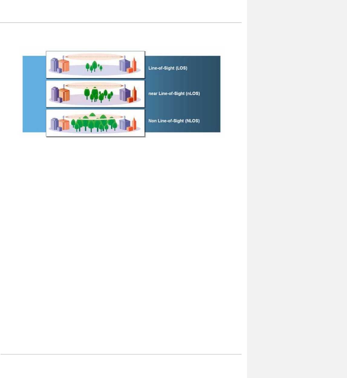
nLOS benefits and limitations
In addition to providing LOS (Line-Of-Sight) connectivity, use of OFDM technology can provide nLOS (near Line-
Of-Sight) connectivity and sometimes NLOS (Non-Line-Of-Sight) connectivity:
• LOS: the installer can see the AP from the SM and the first Fresnel zone is clear.
• nLOS: the installer can see the AP from the SM, but a portion of the first Fresnel zone is blocked.
• NLOS: the installer cannot see the AP from the SM and a portion or even much of the first Fresnel zone is
blocked, but subsequent Fresnel zones are open.
pmp-0047 (March 2014) 1-11
PMP 450 Planning Guide
Figure 1 Line Of Sight Diagram
Whereas multi-pathing degrades a link in some technologies (FSK, for example), OFDM can often use multi-
pathing to an advantage to overcome nLOS, especially in cases where the Fresnel zone is only partially blocked by
buildings, “urban canyons”, or foliage. OFDM tends to help especially when obstacles are near the middle of the
link, and less so when the obstacles are very near the SM or AP.
However, attenuation through walls and trees is substantial for any use of the 2.4/3.5/5.4/5.8 GHz frequency bands.
Even with OFDM, these products should not be expected to penetrate walls or extensive trees and foliage.
Typical deployment
The PMP 450 Series consists of Access Point Modules and Subscriber Modules. The radio link operates on a single
frequency channel in each direction using Time Division Duplex (TDD).
Applications for the PMP 450 Series include:
• High throughput enterprise applications
• nLOS video surveillance in metro areas
• Urban area network extension
• Network extension into areas with foliage
Greenfield deployment
The PMP 450 Series equipment may be deployed as a standalone network deployment offering a high-speed access
network.
1-12 pmp-0047 (March 2014)

PMP 450 Planning Guide
System components
PMP 450 Access Point
• Access Point Module (AP): A connectorized outdoor transceiver unit containing all the radio, networking,
antenna, and surge suppression electronics.
• Access Point Power Supply: An indoor power supply module providing Power-over-Ethernet (PoE) supply to
the Access Point.
• Cabling: Cat 5e cables, grounding cables, and connectors.
PMP 450 Subscriber Module
• Subscriber Module (SM): An integrated-antenna outdoor transceiver unit containing all the radio, antenna,
and networking electronics.
• Subscriber Module Power Supply: An indoor power supply module providing Power-over-Ethernet (PoE)
supply to the Subscriber Module.
• Cabling and lightning protection: Cat 5e cables, grounding cables, connectors and lightning protection (surge
suppression).
• Connectorized Subscriber Module (CSM): An outdoor transceiver unit containing all of the radio and
network electronics that needs to be mated with a customer supplied external antenna.
pmp-0047 (March 2014) 1-13

PMP 450 Planning Guide
Product variants
The PMP 450 Series is available in the following product variants:
Table 1 PMP 450 frequency variants
Variant Region Frequency
Coverage
(MHz)
Channel
Bandwidth
(MHz)
Variant
Notes
2.4 GHz
PMP 450
FCC ISM Band 2400 – 2483.5 5/10/20
3.5 GHz
PMP 450
3300 – 3600 5/10/20 Combined
Transmit power
limited based on
Country Code
setting.
Available center
frequencies
based on
Country Code
setting.
3.6 GHz
PMP 450
3650 – 3700 5/10/20 Combined
Transmit power
limited based on
Country Code
setting.
Available center
frequencies
based on
Country Code
setting.
5.4/5.8-
GHz
PMP 450
FCC UNII Band
ETSI Band B
ETSI Band C
5470 - 5875 10/20 Combined
Transmit power
limited based on
Country Code
setting
5.8-GHz
PMP 450
(US
ONLY)
FCC ISM Band 5725 - 5875 5/10/20 US Only –
locked to US
Country Code
EIRP limit of 36
dBm and 5.8-
GHz Only
1-14 pmp-0047 (March 2014)
PMP 450 Planning Guide
Access Point (AP)
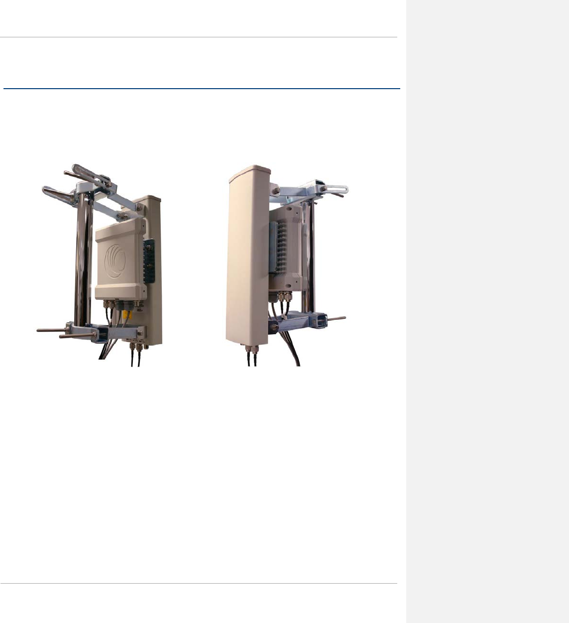
The AP is a self-contained unit that houses both radio and networking electronics. The AP is supplied in a
connectorized configuration for use with an external antenna. Connectorized units with external antennas can cope
with more difficult radio conditions.
Figure 2 AP, Radio unit
Figure 3 AP, antenna
pmp-0047 (March 2014) 1-15
PMP 450 Planning Guide
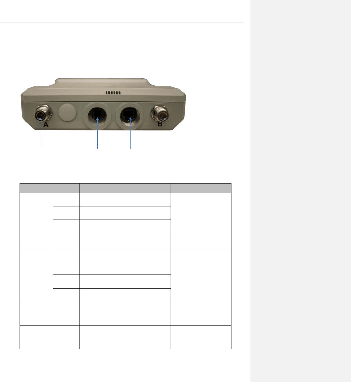
AP interfaces
The AP interfaces are illustrated below.
Figure 4 AP interfaces – 2.4 GHz, 3.5 GHz, 3.6GHz, 5 GHz
Table 2 AP interface descriptions and cabling – 2.4 GHz, 3.5 GHz, 5 GHz
Interface Function Cabling
Path A RF
Port
2.4 GHz -45 degree RF connection to AP antenna
50 ohm RF cable, N-type
3.5 GHz -45 degree RF connection to AP antenna
3.6 GHz -45 degree RF connection to AP antenna
5 GHz Vertical RF connection to AP antenna
Path B RF
Port
2.4 GHz +45 degree RF connection to AP antenna
50 ohm RF cable, N-type
3.5 GHz +45 degree RF connection to AP antenna
3.6 GHz +45 degree RF connection to AP antenna
5 GHz Horizontal RF connection to AP antenna
Sync / Default GPS synchronization signaling provides
power to UGPS module and is the default
plug port.
RJ11 cable, default plug.
Power-over-Ethernet,
Ethernet communications
(management and data)
Power-over-Ethernet, Ethernet
communications (management and data) RJ45 cable
Path A RF Port Sync/Default Ethernet Path B RF Port
1-16 pmp-0047 (March 2014)
PMP 450 Planning Guide
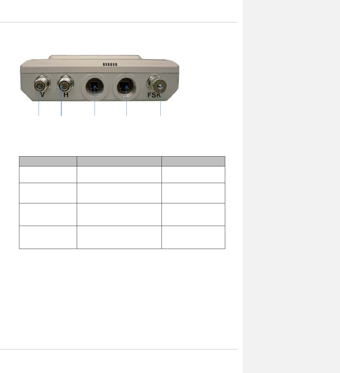
Figure 5 AP interfaces - 5 GHz original layout
Table 3 AP interface descriptions and cabling – 5 GHz original layout
Interface Function Cabling
Path V RF Port Vertical RF connection to AP antenna 50 ohm RF cable, N-type
Path H RF Port Horizontal RF connection to AP antenna 50 ohm RF cable, N-type
Sync / Default GPS synchronization signaling, provides
power to UGPS module. Default plug
port.
RJ11 cable, default plug.
Power-over-Ethernet,
Ethernet communications
(management and data)
Power-over-Ethernet, Ethernet
communications (management and data) RJ45 cable
Path V RF Port Sync/Default Ethernet Unused Path H RF Port
pmp-0047 (March 2014) 1-17
PMP 450 Planning Guide
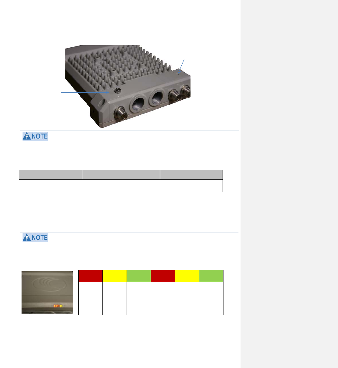
Figure 6 AP ground and equilibrium membrane vent
The ports on the 3.5GHz and 3.6GHz APs are slightly different.
Table 4 AP interface descriptions and cabling – ground lug
Interface Function Cabling
Ground Lug (bottom of unit) For grounding the unit 10 AWG copper wire
AP diagnostic LEDs
The diagnostic LEDs report the following information about the status of the module.
The LED color helps you distinguish position of the LED. The LED color does not indicate any status.
Figure 7 AP diagnostic LEDs, viewed from front of the unit
PWR SYN/1 SES/2 GPS/3 ACT/4 LNK/5
AP Ground
Equilibrium Membrane
Vent (do not cover)
1-18 pmp-0047 (March 2014)
PMP 450 Planning Guide
Table 5 AP LED descriptions
LED Color when active Status information provided Notes
PWR red DC power Always lit when power
is correctly supplied.
SYN/1 yellow Presence of sync Always lit on the AP.
SES/2 green Unused on the AP
GPS/3 red Pulse of sync Continuously lit as pulse as
AP receives pulse.
ACT/4 yellow Presence of data activity
on the Ethernet link
Flashes during data
transfer. Frequency of flash
is not a diagnostic
indication.
LNK/5 green Ethernet link Continuously lit when link
is present.
Network connection
The network connection to a PMP 450 Series AP is made via a 10 BaseT or 100 BaseT Ethernet connection. Power
is provided to the AP over the Ethernet connection using a patented non-standard powering technique.
AP power supply
The AP power supply generates the AP supply voltage (29 VDC) from the external DC source and injects the
supply voltage into the AP.
The power supply is connected to the AP and network equipment using Cat5e cable with RJ45 connectors. See
Cabling and lightning protection on page 1-36.
The PMP 450 AP can use the GigE power injector.
pmp-0047 (March 2014) 1-19

PMP 450 Planning Guide
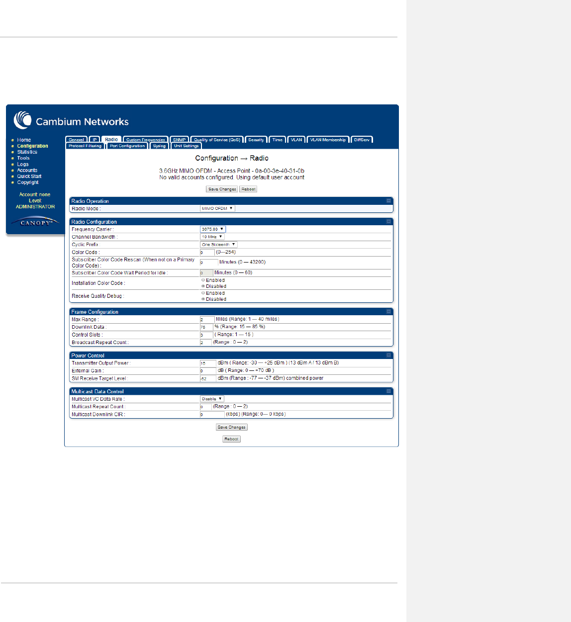
The Radio tab of the AP contains some of the configurable parameters that define how the AP operates.
Table 6 AP Radio attributes
Attribute Meaning
Radio Mode Reserved for future modes of operation.
Frequency Band Select the desired operating frequency band.
Frequency Carrier Specify the frequency for the module to transmit. The default for this parameter is
None. For a list of channels in the band, see the drop-down list on the radio GUI.
Channel Bandwidth The channel size used by the radio for RF transmission. The setting for the
channel bandwidth must match between the AP and the SM. Note: Release 12.1
introduces the Band Scan feature which will allow the SM to scan all Channel
Bandwidths.
Cyclic Prefix OFDM technology uses a cyclic prefix, where a portion of the end of a symbol
(slot) is repeated at the beginning of the symbol to allow multi-pathing to settle
before receiving the desired data. A 1/16 cyclic prefix means that for every 16
bits of throughput data transmitted, an additional bit is used.
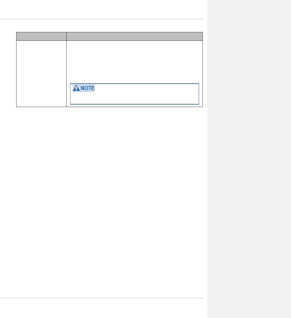
Color Code
Specify a value from 0 to 254. For registration to occur, the color code of the SM
and the AP must match. Color code is not a security feature. Instead, color code is
a management feature, typically for assigning each sector a different color code.
Color code allows you to force an SM to register to only a specific AP, even
where the SM can communicate with multiple APs. The default setting for the
color code value is 0. This value matches only the color code of 0 (not all 255
color codes).
Max Range
Enter a number of miles (or kilometers divided by 1.61, then rounded to an
integer) for the furthest distance from which an SM is allowed to register to this
AP. Do not set the distance to any greater number of miles. A greater distance
• does not increase the power of transmission from the AP.
• can reduce aggregate throughput.
Regardless of this distance, the SM must meet the minimum requirements for an
acceptable link. If the AP is in cluster, then you must set this parameter on all
other APs in the cluster exactly the same, except as described in the NOTE
admonition below. The default value of this parameter is 2 miles (3.2 km).
pmp-0047 (March 2014) 1-21
PMP 450 Planning Guide
Attribute Meaning
Downlink Data
Specify the percentage of the aggregate throughput for the downlink (frames
transmitted from the AP to the subscriber). For example, if the aggregate (uplink
and downlink total) throughput on the AP is 90 Mb, then 75% specified for this
parameter allocates 67.5 Mb for the downlink and 22.5 Mb for the uplink. The
default for this parameter is 75%. This parameter must be set in the range of 15%
- 85%, otherwise the invalid input will not be accepted and the previously-entered
valid setting will be used.
In order to prevent self-interference, the frame configuration needs to align.
This includes Downlink Data, Max Range and Control Slots.
1-22 pmp-0047 (March 2014)

PMP 450 Planning Guide
Attribute Meaning
Control Slots
This field indicates the number of (reserved) control slots configured by the
operator. The SM uses reserved control slots and unused data slots for bandwidth
requests
Uplink Data Slots are used first for data. If they are not needed for data in a given
frame, the remaining data slots can be used by the SMs for bandwidth requests.
This allows SMs in sectors with a small number of control slots configured to still
successfully transmit bandwidth requests using unused data slots.
A higher number of control slots give higher probability that an SM’s bandwidth
request will be correctly received when the system is heavily loaded, but with the
tradeoff that sector capacity is reduced, so there will be less capacity to handle the
request. The sector capacity reduction is about 200 kbps for each Control Slot
configured in a 20 MHz channel at QPSK SISO modulation. The reduction in
sector capacity is proportionally higher at MIMO modulations (2 times at QPSK
MIMO, 4 times at 16 QAM MIMO, 6 times at 64 QAM MIMO and 8 times at
256 QAM MIMO). If too few reserved control slots are specified, then latency
increases in high traffic periods. If too many are specified, then the maximum
capacity is unnecessarily reduced.
The suggested Control Slot settings as a function of the number of active VCs in
the sector are shown in the table below.
Number of VCs Recommended Number of
Control Slots
1 to 10
3
11 to 50
4
51 to 150
6
151 and above
8
Note that each SM uses one or two VCs. All SMs have a Low Priority Channel
that uses one VC; if the High Priority Channel is enabled for the SM, then the SM
uses a second VC. Therefore the number of active VCs in a sector is greater than
or equal to the number of SMs registered to the AP in the sector. For example, a
network including 20 SMs with High Priority Channel disabled and 20 SMs with
High Priority Channel enabled has 60 active VCs and may be configured with 6
Control Slots.
In a typical cluster, each AP should be set to the same number of control slots to
assure proper timing in the send and receive cycles. However, where high
incidence of small packets exists, as in a sector that serves several VoIP streams,
additional control slots may provide better results. For APs in a cluster of
mismatched control slots setting, or where PMP 450 is collocated with radios
using different technologies, like PMP 430 or FSK, in the same frequency band,
use the frame calculator.
pmp-0047 (March 2014) 1-23
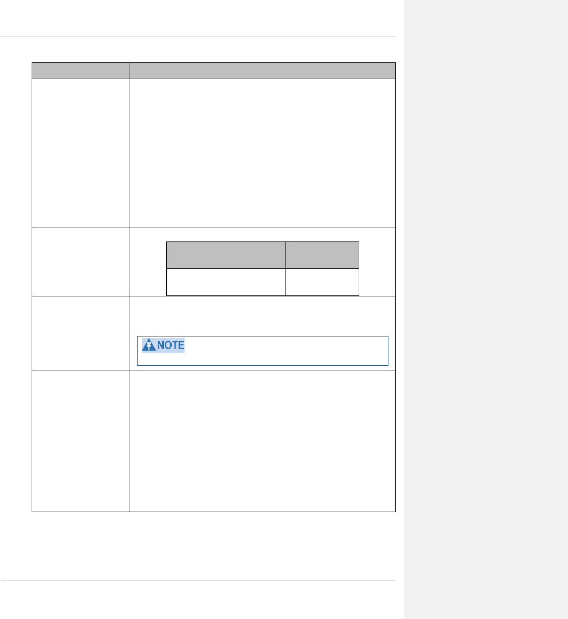
PMP 450 Planning Guide
Attribute Meaning
Transmitter Output Power
This value represents the combined power of the AP’s two transmitters.
Nations and regions may regulate transmitter output power. For example
• 5.4/5.8-GHz modules are available as connectorized radios, which require the
operator to adjust power to ensure regulatory compliance.
The professional installer of the equipment has the responsibility to
• maintain awareness of applicable regulations.
• calculate the permissible transmitter output power for the module.
• confirm that the initial power setting is compliant with national or regional
regulations.
• confirm that the power setting is compliant following any reset of the module
to factory defaults.
External Gain This value represents the amount of gain introduced by an external antenna.
Module Type Recommended
Setting
OFDM connectorized with antenna
that was purchased with it 17
Receive Quality Debug To aid in link performance monitoring, the AP and SM now report the number of
fragments received per modulation (i.e. QPSK, 16-QAM, 64-QAM) and per
channel (polarization).
Due to CPU load, this will slightly degrade packet per second processing.
Broadcast Repeat Count
The default is 2 repeats (in addition to the original broadcast packet, for a total of
3 packets sent for every one needed), and is settable to 1 or 0 repeats (2 or 1
packets for every broadcast).
ARQ (Automatic Repeat reQuest) is not present in downlink broadcast packets,
since it would cause unnecessary uplink traffic from every SM for each broadcast
packet. For successful transport without ARQ, the AP repeats downlink broadcast
packets. The SMs filter out all repeated broadcast packets and, thus, do not
transport further.
The default of 2 repeats is optimum for typical uses of the network as an internet
access system. In applications with heavy download broadcast such as video
distribution, overall throughput is significantly improved by setting the repeat
count to 1 or 0. This avoids flooding the downlink with repeat broadcast packets.
1-24 pmp-0047 (March 2014)

PMP 450 Planning Guide
Attribute Meaning
Subscriber Color Code
Rescan (When not on a
Primary Color Code)
This timer may be utilized to initiate SM rescans in order to register to an AP
configured with the SM‘s primary color code.
The time (in minutes) for a subscriber to rescan (if this AP is not configured with
the SM‘s primary color code). This timer will only fire once – if the Subscriber
Color Code Wait Period for Idle timer is configured with a nonzero value and
the Subscriber Color Code Rescan expires, the Subscriber Color Code Wait
Period for Idle will be started. If the Subscriber Color Code Wait Period for
Idle timer is configured with a zero value and the Subscriber Color Code
Rescan timer expires, the SM will immediately go into rescan mode
Subscriber Color Code Wait
Period for Idle
The time (in minutes) for a subscriber to rescan while idle (if this AP is not
configured with the SM’s primary color code). This timer will fire periodic
events. The fired event determines if any RF unicast traffic (either inbound or
outbound) has occurred since the last event. If the results of the event determine
that no RF unicast traffic has occurred (SM is idle), then the subscriber will
rescan.
Installation Color Code With this feature enabled on the AP and SM, operators may install and remotely
configure SMs without having to configure matching color codes between the
modules. While the SM is accessible for configuration from above the AP (for
remote provisioning) and below the SM (for local site provisioning), no user data
is passed over the radio link. When using the Installation Color Code feature,
ensure that the SM is configured with the factory default Color Code
configuration (Color Code 1 is “0”, Color Code 2-10 set to “0” and “Disable”).
The status of the Installation Color Code can be viewed on the AP Eval web GUI
page, and when the SM is registered using the Installation Color Code the
message “SM is registered via ICC – Bridging Disabled!” is displayed in red on
every SM GUI page. The Installation Color Code parameter is configurable
without a radio reboot for both the AP and SM. If an SM is registered via
Installation Color Code and the feature is then disabled, operators will need to
reboot the SM or force it to reregister (i.e. using the Rescan APs functionality on
the AP Eval page).
SM Receive Target Level Each SM’s Transmitter Output Power is automatically set by the AP. The AP
monitors the received power from each SM, and adjusts each SM’s Transmitter
Output Power so that the received power at the AP from that SM is not greater
what is set in this field. This value represents a “single-port” power perceived on
the SM.
Further reading on the AP
For more information on the AP, refer to the following:
• AP or SM site selection on page 1-65 describes how to select a site for the AP or SM.
pmp-0047 (March 2014) 1-25
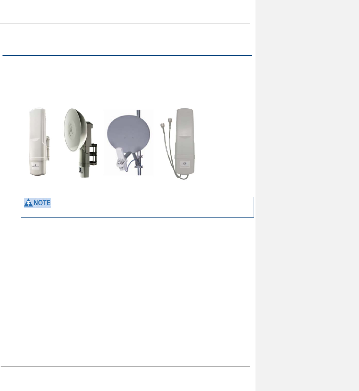
PMP 450 Planning Guide
Subscriber Module (SM)
The SM is a self-contained unit that houses both radio and networking electronics. The SM is available in a
connectorized model and also in an integrated antenna configuration, but may also be used with a passive reflector
dish or CLIP (Cassegrain Lens for Improved Performance, 5 GHz only).
Figure 9 PMP 450 Series SM
3.5 GHz and 3.6 GHz PMP 450 SMs appear a bit different from the existing PMP 450 SMs.
Mounting brackets
For mounting PMP 450 SMs, Cambium Networks offers the SMMB1A mounting bracket.
Network connection
The network connection to a PMP 450 Series SM is made via a 10 BaseT or 100 BaseT Ethernet connection.
Power is provided to the SM over the Ethernet connection using a patented non-standard powering technique.
SM power supply
The SM power supply generates the SM supply voltage (29 VDC) from the external DC source and injects the
supply voltage into the SM.
The power supply is connected to the SM and network equipment using Cat5e cable with RJ45 connectors. Refer
to Cabling and lightning protection on page 1-36.
1-26 pmp-0047 (March 2014)
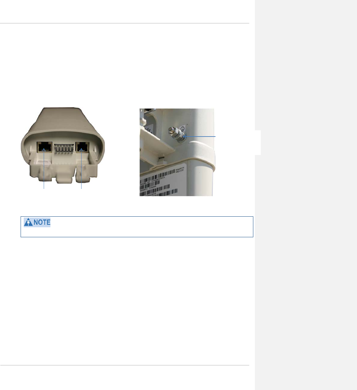
PMP 450 Planning Guide
Further reading on the SM
For more information on the SM, refer to the following:
• AP or SM site selection on page 1-65 describes how to select a site for the SM.
SM interfaces
Figure 10 SM interfaces
3.5 GHz and 3.6 GHz SMs appear a bit different from the existing 450 SMs.
Ethernet Sync/Default
SM Ground
(connectorized
models)
pmp-0047 (March 2014) 1-27
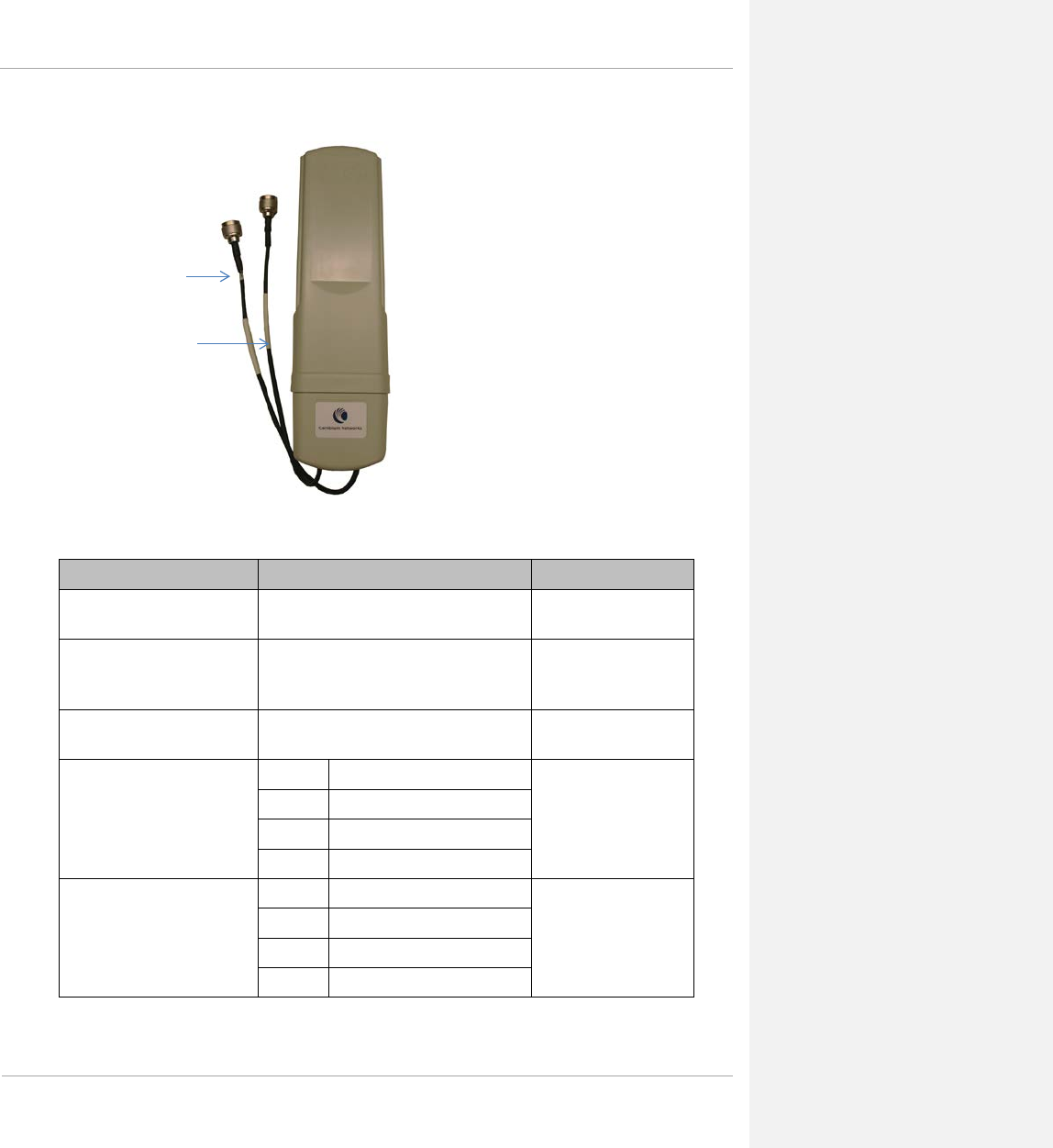
PMP 450 Planning Guide
Figure 11 Connectorized SM
Table 7 SM Interfaces
Interface Function Cabling
Ethernet Power-over-Ethernet, Ethernet
communications (management and data) RJ45 Cable
Sync / Default GPS synchronization signaling provides
power to UGPS module and is the default
plug port.
RJ11 cable, default plug
Ground Lug (rear of unit,
connectorized only)
For grounding the unit 10 AWG copper wire
External antenna cable, path A
(labeled “A”)
2.4 GHz -45 degree antenna connection 50 ohm RF cable, N-type
3.5 GHz -45 degree antenna connection
3.6 GHz -45 degree antenna connection
5 GHz Vertical antenna connection
External antenna cable, path B 2.4 GHz +45 degree antenna connection 50 ohm RF cable, N-type
3.5 GHz +45 degree antenna connection
3.6 GHz +45 degree antenna connection
5 GHz Horizontal antenna connection
External
antenna cable,
path A (labeled
“A”)
External
antenna cable,
path B
1-28 pmp-0047 (March 2014)
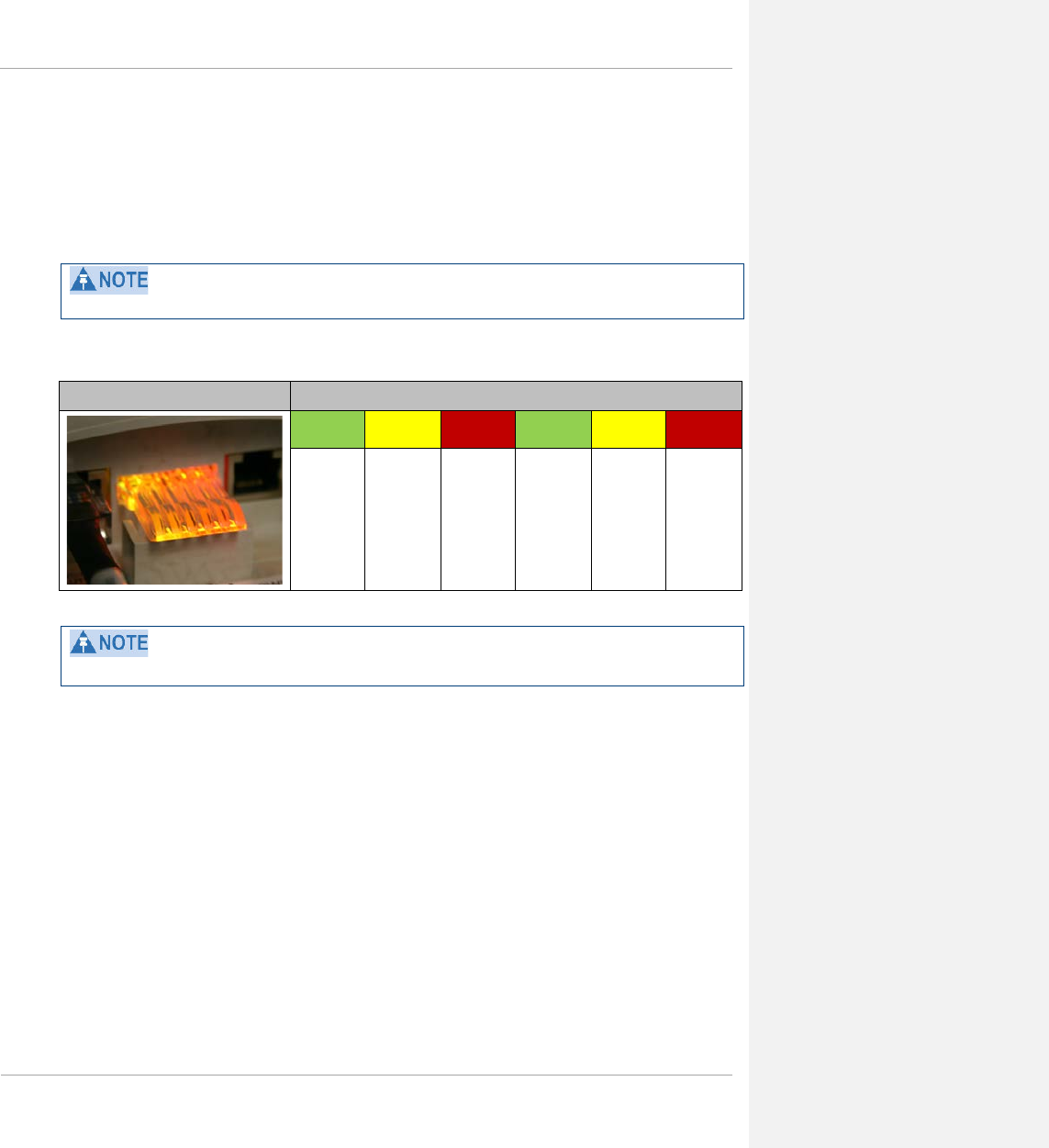
PMP 450 Planning Guide
SM diagnostic LEDs
The diagnostic LEDs report the following information about the status of the module. The SM LEDs provide
different status based on the mode of the SM. An SM in “operating” mode will register and pass traffic normally.
An SM in “aiming” mode will not register or pass traffic, but will display (via LED panel) the strength of received
radio signals (based on radio channel selected via Tools, Alignment).
The LED color helps you distinguish position of the LED. The LED color does not indicate any status.
Figure 12 SM diagnostic LEDs, viewed from front of the unit
SM LED Display LED Labels
LNK/5 ACT/4 GPS/3 SES/2 SYN/1 PWR
The LED display of the 3.5 GHz and 3.6 GHz SMs appear a bit different from the existing 450 SMs.
pmp-0047 (March 2014) 1-29

PMP 450 Planning Guide
Table 8 SM diagnostic LED descriptions
Status information provided
LED Color
when
active
SM in
“Operating”
Mode
SM in “Aiming”
Mode Notes
LNK/5 green Ethernet link
These five LEDs act
as a bar graph to
indicate the relative
quality of alignment.
As power level
improves during
alignment, more of
these LEDs are lit.
Continuously lit when link is
present.
ACT/4 yellow Presence of data activity
on the Ethernet link
Flashes during data transfer.
Frequency of flash is not a
diagnostic indication.
GPS/3 red Interference
On - high interference.
Blinking - medium interference.
Off - low interference.
SES/2 green
Strong Receive Signal
Power
Blinking from slow to full-on to
indicate strong power, getting
stronger.
SYN/1 yellow
Medium Receive
Signal Power
Blinking from slow to full-on to
indicate medium power, getting
stronger.
PWR red Registration Indicator
Off when registered to AP.
On when not registered to AP.
1-30 pmp-0047 (March 2014)
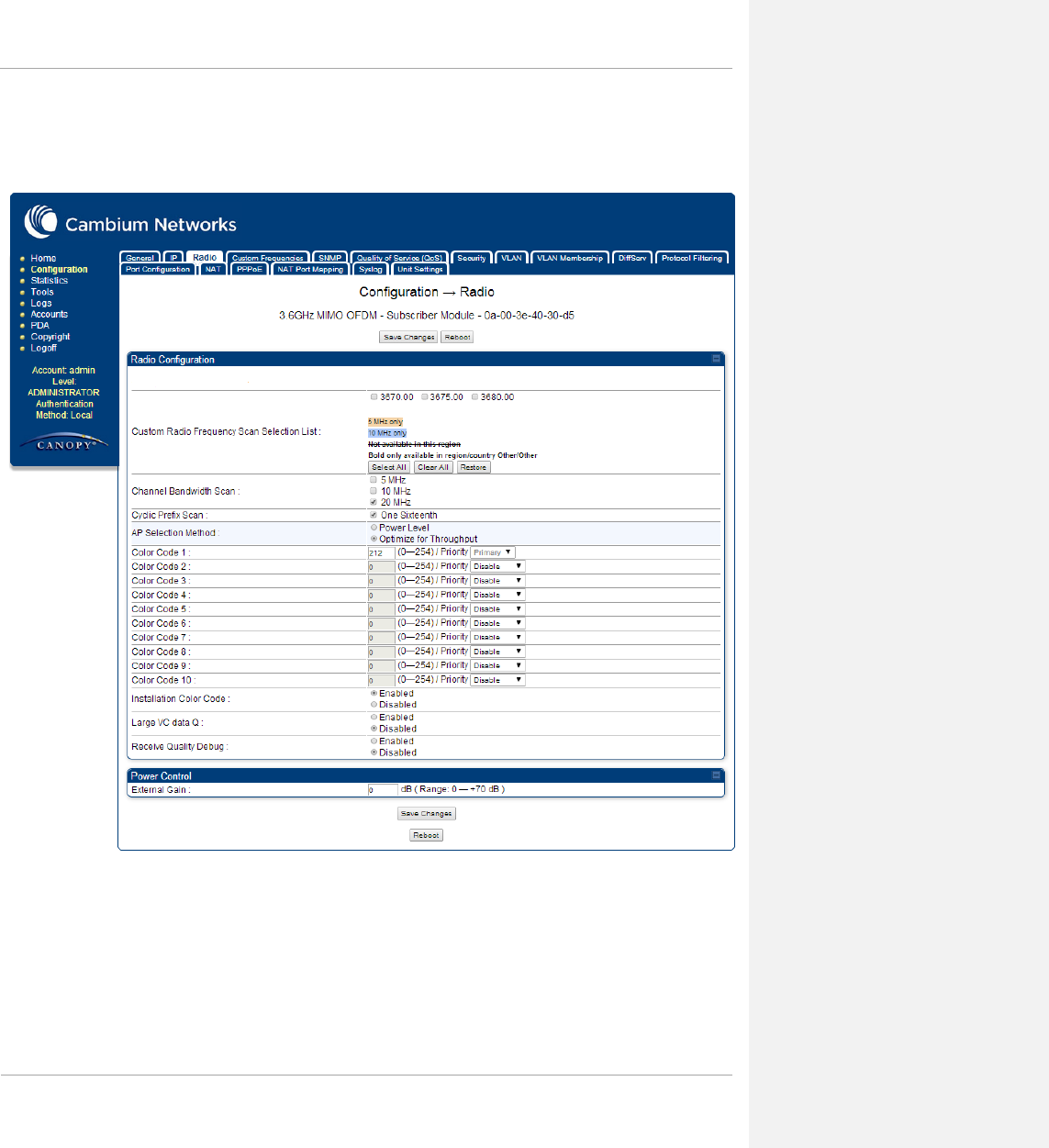
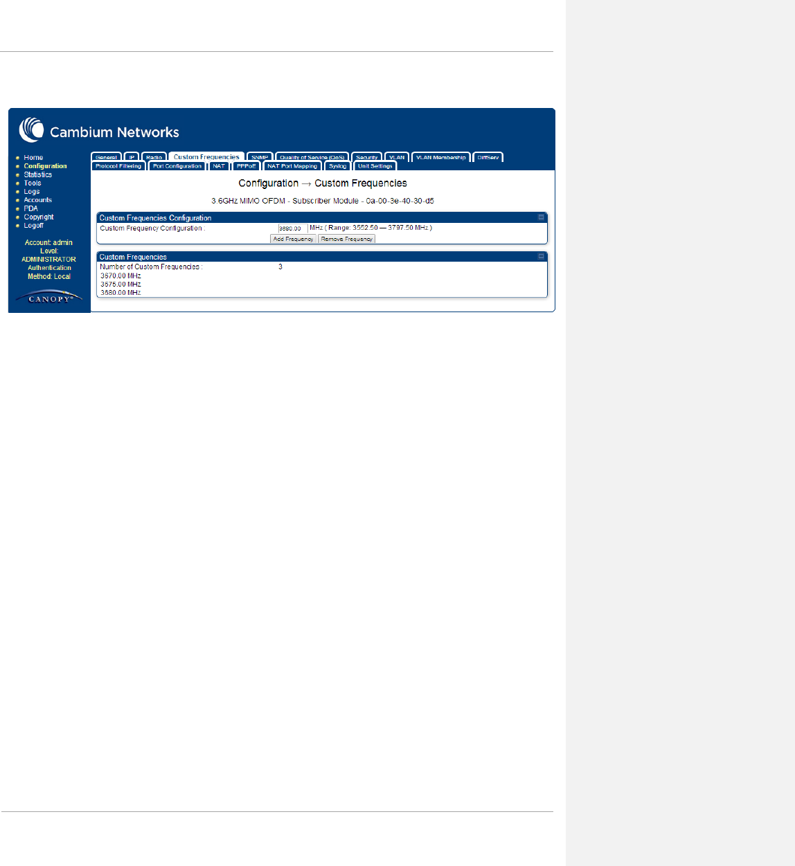

PMP 450 Planning Guide
In the radio tab of the SM, you may set the following parameters.
Table 9 SM Radio attributes
Attribute Meaning
Custom Radio Frequency
Scan Selection List
Check any frequency that you want the SM to scan for AP transmissions.
Prior to System Release 13.1, the PMP 450 SM boot sequence included loading
the current channel bandwidth (10 MHz or 20 MHz, but not both) and frequency
band configuration (3.6 GHz) and scanning selected frequencies in the respective
frequency band. After a scan of all the selected frequencies the SM would attempt
to register to the best AP based on the SM’s current configuration.
With the introduction of the Full Spectrum Band Scan feature in 12.0.3, SMs first
boot into the smallest selected channel bandwidth (10 MHz, if selected) and scan
all selected frequencies across the 3.6GHz frequency bands.
After this scan, if a wider channel bandwidth is selected (20 MHz), the SM
automatically changes to 20 MHz channel bandwidth and then scans for APs.
After the SM finishes this final scan it will evaluate the best AP with which to
register. If required for registration, the SM changes its channel bandwidth back
to 10 MHz to match the best AP.
The SM will attempt to connect to an AP based on power level (which affects the
modulation state), channel bandwidth (which affects throughput) and number of
SM registrations to the AP (which affects system contention performance).
If it is desired to prioritize a certain AP over other available APs, operators may
use the Color Code Priority feature on the SM. Utilization of the Color Code
feature on the AP is recommended to further constrain the SM’s AP selection.
If the SM does not find any suitable APs for registration after scanning all
channel bandwidths, the SM restarts the scanning process beginning with the
smallest configured channel bandwidth.
By default, beginning with System Release 12.0.3 SMs are configured to scan all
available frequencies and all available channel bandwidths. This allows operators
to install SMs and allow them to register with no pre-configuration or staging
required. SMs upgraded from a previous release to 12.0.3 retain frequency and
channel bandwidth configuration.
Selecting multiple frequencies and multiple channel bandwidths impacts the SM
scanning time. The biggest consumption of time is in the changing of the SM
channel bandwidth setting. The worst case scanning time is approximately two
minutes after bootup (SM with all frequencies and channel bandwidths selected
and registering to an AP at 10 MHz). If only one channel bandwidth is selected
the time to scan all the available frequencies and register to an AP is
approximately one minute after bootup.
Other scanning features such as Color Code, Installation Color Code, and
RADIUS authentication are unaffected by the Full Band Scan feature.
pmp-0047 (March 2014) 1-33

PMP 450 Planning Guide
Attribute Meaning
Channel Bandwidth The channel size used by the radio for RF transmission.
Selecting multiple channel bandwidths will increase registration and re-
registration times.
Cyclic Prefix Scan The cyclic prefix for which AP scanning is executed.
AP Selection Method Operators may configure the method by which a scanning SM selects an AP. By
default, AP Selection Method is set to “Optimize for Throughput”, which has
been the mode of operation in releases prior to 12.0.3.1.
Power Level: AP selection based solely on power level
OR
Optimize for Throughput: AP selection based on throughput optimization – the
selection decision is based on power level (which affects the modulation state),
channel bandwidth (which affects throughput) and number of SM registrations to
the AP (which affects system contention performance).
Color Code 1 to 10 Color code allows you to force the SM to register to only a specific AP, even
where the SM can communicate with multiple APs. For registration to occur, the
color code of the SM and the AP must match. Specify a value from 0 to 254.
Color code is not a security feature. Instead, color code is a management feature,
typically for assigning each sector a different color code. The default setting for
the color code value is 0. This value matches only the color code of 0 (not all 255
color codes).
SMs may be configured with up to 10 color codes. These color codes can be
tagged as Primary, Secondary, or Tertiary, or Disable. When the SM is
scanning for APs, it will first attempt to register to an AP that matches one of the
SM’s primary color codes. Failing that, the SM will continue scanning and
attempt to register to an AP that matches one of the SM’s secondary color codes.
Failing that, the SM will continue scanning and attempt to register to an AP that
matches one of the SM’s tertiary color codes. This is all done in the scanning
mode of the SM and will repeat until a registration has occurred.
Color codes in the same priority group are treated equally. For example, all APs
matching one of the SM’s primary color codes are analyzed equally. Likewise,
this evaluation is done for the secondary and tertiary groups in order. The
analysis for selecting an AP within a priority group is based on various inputs,
including signal strength and number of SMs already registered to each AP.
The first color code in the configuration is the pre-Release 9.5 color code. Thus,
it is always a primary color code for legacy reasons.
The color codes can be disabled, with the exception of the first color code.
1-34 pmp-0047 (March 2014)
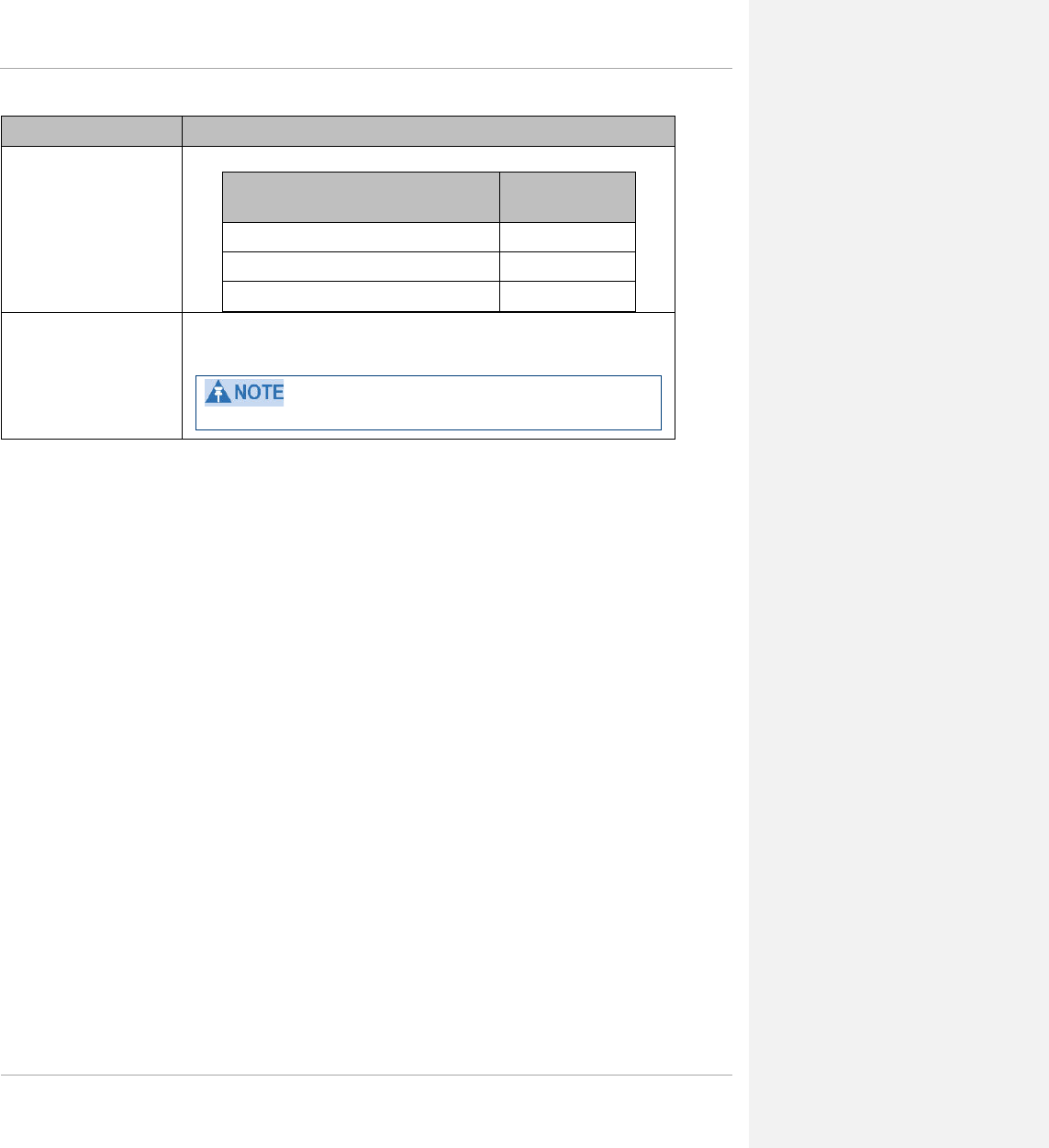
PMP 450 Planning Guide
Attribute Meaning
External Gain This value represents the amount of gain introduced by an external antenna.
Module Type Recommended
Setting
OFDM integrated antenna with LENS 5
OFDM Integrated antenna with CLIP 8
OFDM integrated antenna with reflector dish 15
Receive Quality Debug To aid in link performance monitoring, the AP and SM now report the number of
fragments received per modulation (i.e. QPSK, 16-QAM, 64-QAM) and per
channel (polarization).
Due to CPU load, this will slightly degrade packet per second processing.
pmp-0047 (March 2014) 1-35

PMP 450 Planning Guide
Cabling and lightning protection
This section describes the cabling and lightning protection components of a PMP 450 installation.
PMP and lightning protection
Due to the full metallic connection to the tower or support structure through the AP antenna, grounding the AP and
installing a 600SS surge suppressor at the Ethernet cable building ingress is strongly recommended. This
suppresses overvoltages and overcurrents such as those caused by near-miss lightning. APs provide a grounding
lug for grounding to the tower or support structure.
The PMP 450 Series is not designed to survive direct lightning strikes. For this reason the unit should not be
installed as the highest point in a localized area.
Outdoor connections
The term ‘drop cable’ refers to the cable that is used for all connections that terminate outside the building, for
example, connections between the AP/SM, surge suppressors (if installed), GPS receivers (if installed) and the
power supply injector.
The following practices are essential to the reliability and longevity of cabled connections:
• Use only shielded cables and connectors to resist interference and corrosion
• For vertical runs, provide cable support and strain relief
• Include a 2 ft (0.6 m) service loop on each end of the cable to allow for thermal expansion and contraction and
to facilitate terminating the cable again when needed
• Include a drip loop to shed water so that most of the water does not reach the connector at the device
• Properly crimp all connectors
• Use dielectric grease on all connectors to resist corrosion
1-36 pmp-0047 (March 2014)
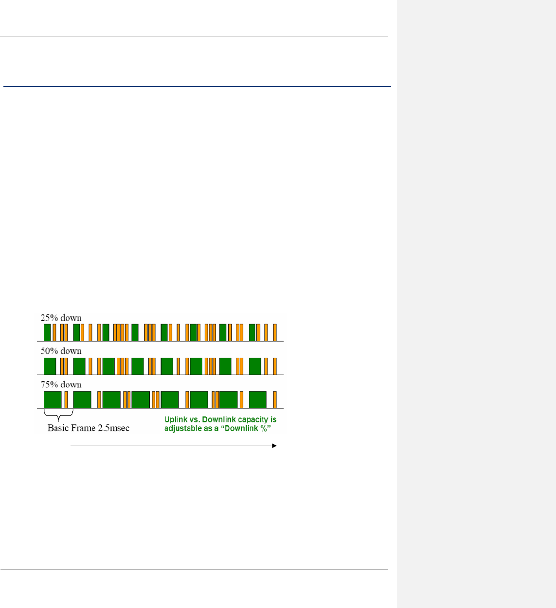
PMP 450 Planning Guide
Wireless operation
This section describes how the PMP 450 wireless link is operated, including modulation modes, power control and
security.
Time division duplexing
The system uses Time Division Duplexing (TDD) – one channel alternately transmits and receives rather than using
one channel for transmitting and a second channel for receiving. To accomplish TDD, the AP must provide sync to
its SMs. Furthermore, collocated APs must be synced together – an unsynchronized AP that transmits during the
receive cycle of a collocated AP can prevent a second AP from being able to decode the signals from its SMs. In
addition, across a geographical area, APs that can “hear” each other benefit from using a common sync to further
reduce self-interference within the network.
Modules use TDD on a common frequency to divide frames for uplink (orange) and downlink (green) usage, as
shown in the figure below.
For more information on synchronization configuration options, see section Planning for co-location and using the
OFDM Frame Calculator Tool on page 1-99.
Figure 15 TDD Frame Division
OFDM and channel bandwidth
The PMP 450 Series transmits using Orthogonal Frequency Division Multiplexing (OFDM). The channel
bandwidth of the OFDM signal may be configured to 5 MHz (2.4 GHz, 3.5GHz, 3.6 GHz and 5.8 GHz only), 10
MHz or 20 MHz.
Time
pmp-0047 (March 2014) 1-37

PMP 450 Planning Guide
Link operation – Dynamic Rate Adapt
PMP 450 Series products offer five levels or speeds of operation – 1x (QPSK), 2x (QPSK-MIMO-B), 4x (16QAM-
MIMO-B), 6x (64QAM-MIMO-B), and 8x (256QAM-MIMO-B). If received power is less due to distance between
the AP and the SM or due to obstructions, or if interference affects the RF environment, the system will
automatically and dynamically adjust links to the best operation level.
The system chooses its operation rate dynamically, based on an internal ARQ (Automatic Repeat reQuest) error
control method. With ARQ, every data slot of every frame sent over the air (except downlink broadcast) is expected
to be acknowledged by the receiver, and if acknowledgement is not received, the data is resent. The sending unit
monitors these resends, and adjusts the operation rate accordingly. A normal system may have links that change
levels of operation as the RF environment changes. Furthermore, the links operate independently; normal operation
can have a downlink running at 6x while the uplink RF environment only supports 2x.
Optimal sector utilization involves having as many links as possible running at 8x. This provides as much capacity
as possible for the sector.
1-38 pmp-0047 (March 2014)

PMP 450 Planning Guide
Table 10 Link Budget Details – Dynamic Rate Adapt, 5.4 GHz
Product Parameter
Performance Details
1x
2x
4x
6x
8x
PMP 450*†
Modulation QPSK-SISO QPSK-MIMO 16-QAM-MIMO 64-QAM-MIMO 256-QAM-MIMO
5.4GHz Max.
LOS Link
Budget (no fade
margin) – 20
MHz channel
bandwidth
with Integrated
SM antenna 4.8 mi / 7.68 km 3.4 mi / 5.44 km 1.5 mi / 2.4 km 0.7 mi / 1.12 km 0.2 mi / 0.32 km
with Reflector
Dish that adds 14
dB to SM Range 8.2 mi / 13.12 km 5.8 mi / 9.28 km 2.6 mi / 4.16 km 1.2 mi / 1.92 km 0.5 mi / 0.8 km
5.4GHz Max.
LOS Link
Budget (no fade
margin) – 10
MHz channel
bandwidth
with Integrated
SM antenna 4.3 mi / 6.88 km 3.1 mi / 4.96 km 1.6 mi / 2.56 km 0.7 mi / 1.12 km 0.2 mi / 0.32 km
with Reflector
Dish that adds 14
dB to SM Range 7.5 mi / 12 km 5.3 mi / 8.48 km 2.4 mi / 3.84 km 1.1 mi / 1.76 km 0.3 mi / 0.48 km
5.4GHz Max.
LOS Link
Budget (no fade
margin) – 5 MHz
channel
bandwidth
with Integrated
SM antenna 4 mi / 6.4 km 2.8 mi / 4.48 km 1.4 mi / 2.24 km 0.9 mi / 1.44 km 0.1 mi / 0.16 km
with Reflector
Dish that adds 14
dB to SM Range 7.3 mi / 11.68 km 5.2 mi / 8.32 km 2.3 mi / 3.68 km 1 mi / 1.6 km 0.3 mi / 0.48 km
5.4GHz Max.
Aggregate
Throughput with
1/16 Cyclic
Prefix to 1 SM
(75%/25%
DL/UL Ratio) –
RF Link Test
20 MHz
Channel:
(up+down) 13 Mbps 30 Mbps 60 Mbps 98 Mbps 128 Mbps
10 MHz
Channel:
(up+down) 6 Mbps 13 Mbps 26 Mbps 42 Mbps 55 Mbps
5 MHz Channel:
(up+down) 2 Mbps 4 Mbps 8 Mbps 14 Mbps 18 Mbps
5.4GHz Nominal
Per-Chain
Receive SM RX
Sensitivity
(including FEC)‡
20 MHz Channel -86 dBm -86 dBm -79 dBm -72 dBm -61 dBm
10 MHz Channel -88 dBm -88 dBm -82 dBm -75 dBm -62 dBm
5 MHz Channel -90 dBm -90 dBm -84 dBm -80 dBm -64 dBm
Link Budget,
Integrated (dB)
20 MHz Channel 124.9 121.9 114.9 107.9 96.9
10 MHz Channel 124 121 115.1 108 94.8
5 MHz Channel 123.3 120.3 114.4 110 94.3
* Maximum setting of Max Range parameter is 40 mi.
† Transmit power complies with FCC regulatory requirements.
‡ PMP 450 devices include a dual polar antenna; Channel A (Vertical) and Channel B (Horizontal). Listed receive
sensitivity corresponds to single-channel readings.
pmp-0047 (March 2014) 1-39

PMP 450 Planning Guide
Table 11 Link Budget Details – Dynamic Rate Adapt, 5.8 GHz
§ Maximum setting of Max Range parameter is 40 mi.
** PMP 450 devices include a dual polar antenna; Channel A (Vertical) and Channel B (Horizontal). Listed receive
sensitivity corresponds to single-channel readings.
Product Parameter
Performance Details
1x
2x
4x
6x
8x
PMP 450§
Modulation QPSK-SISO QPSK-MIMO 16-QAM-MIMO 64-QAM-MIMO 256-QAM-MIMO
5.8GHz Max.
LOS Link Budget
(no fade margin)
– 20 MHz
channel
bandwidth
with Integrated
SM antenna 8.5 mi / 13.6 km 6 mi / 9.6 km 2.7 mi / 4.32 km 1.1 mi / 1.76 km 0.3 mi / 0.48 km
with Reflector
Dish that adds 14
dB to SM Range 40 mi / 64 km 30.3 mi / 48.48
km 13.7 mi / 21.92
km 5.6 mi / 8.96
km 1.7 mi / 2.72 km
5.8GHz Max.
LOS Link Budget
(no fade margin)
– 10 MHz
channel
bandwidth
with Integrated
SM antenna 11.7 mi / 18.72
km 8.3 mi / 13.28 km 3.6 mi / 5.76 km 1.5 mi / 2.4 km 0.5 mi / 0.8 km
with Reflector
Dish that adds 14
dB to SM Range
32.9 mi / 52.64
km 23.3 mi / 37.28
km 10.3 mi / 16.48
km 4.1 mi / 6.56 km 1.3 mi / 2.08 km
5.8GHz Max.
LOS Link Budget
(no fade margin)
– 5 MHz channel
bandwidth
with Integrated
SM antenna 14.5 mi / 23.2 km 10.3 mi / 16.48
km 5.1 mi / 8.16 km 2.2 mi / 3.52 km 0.6 mi / 0.96 km
with Reflector
Dish that adds 14
dB to SM Range 40 mi / 64 km 28.9 mi / 46.24
km 14.3 mi / 22.88
km 6.3 mi / 10.08 km 1.7 mi / 2.72 km
5.8GHz Max.
Aggregate
Throughput with
1/16 Cyclic
Prefix to 1 SM
(75%/25%
DL/UL Ratio) –
RF Link Test
20 MHz Channel:
(up+down) 13 Mbps 30 Mbps 60 Mbps 98 Mbps 128 Mbps
10 MHz Channel:
(up+down) 6 Mbps 13 Mbps 26 Mbps 42 Mbps 55 Mbps
5 MHz Channel:
(up+down) 2 Mbps 4 Mbps 8 Mbps 14 Mbps 18 Mbps
5.8GHz Nominal
Per-Chain
Receive SM RX
Sensitivity
(including
FEC)**
20 MHz Channel -87 dBm -87 dBm -80 dBm -72 dBm -62 dBm
10 MHz Channel -90 dBm -90 dBm -83 dBm -76 dBm -64 dBm
5 MHz Channel -91 dBm -91 dBm -85 dBm -79 dBm -69 dBm
Link Budget,
Integrated (dB)
20 MHz Channel 130.5 127.5 120.6 112.8 102.5
10 MHz Channel 133.2 130.2 123.1 115.1 105
5 MHz Channel 135.1 132.1 126 118.9 107.5
1-40 pmp-0047 (March 2014)

PMP 450 Planning Guide
Table 12 Link Budget Details – Dynamic Rate Adapt, 2.4GHz
Product Parameter
Performance Details
1x
2x
4x
6x
8x
PMP 450††
Modulation QPSK-SISO QPSK-MIMO 16-QAM-MIMO 64-QAM-MIMO 256-QAM-MIMO
2.4GHz Max. LOS
Link Budget (no
fade margin) – 20
MHz channel
bandwidth
with Integrated
SM antenna 15.2 mi / 24.32 km 10.8 mi / 17.28 km 5.4 mi / 8.64 km 2.4 mi / 3.84 km 1.1 mi / 1.76 km
with Reflector
Dish that adds 12
dB to SM Range 40 mi / 64 km 40 mi / 64 km 21.5 mi / 34.4 km 9.6 mi / 15.36 km 4.3 mi / 6.88 km
2.4GHz Max. LOS
Link Budget (no
fade margin) – 10
MHz channel
bandwidth
with Integrated
SM antenna 24.1 mi / 38.56 km 17.1 mi / 27.36 km 7.3 mi / 11.68 km 3.6 mi / 5.76 km 1 mi / 1.6 km
with Reflector
Dish that adds 12
dB to SM Range 40 mi / 64 km 40 mi / 64 km 29 mi / 46.4 km 14.4 mi / 23.04 km 3.8 mi / 6.08 km
2.4GHz Max. LOS
Link Budget (no
fade margin) – 5
MHz channel
bandwidth
with Integrated
SM antenna 27.1 mi / 43.36 km 19.2 mi / 30.72 km 10.8 mi / 17.28 km 4.3 mi / 6.88 km 1.4 mi / 2.24 km
with Reflector
Dish that adds 12
dB to SM Range 40 mi / 64 km 40 mi / 64 km 40 mi / 64 km 17.1 mi / 27.36 km 5.4 mi / 8.64 km
2.4GHz Max.
Aggregate
Throughput with
1/16 Cyclic Prefix
to 1 SM
(75%/25% DL/UL
Ratio) – RF Link
Test
20 MHz Channel:
(up+down) 13 Mbps 30 Mbps 59 Mbps 96 Mbps 129 Mbps
10 MHz Channel:
(up+down) 6 Mbps 13 Mbps 26 Mbps 42 Mbps 55 Mbps
5 MHz Channel:
(up+down) 2 Mbps 4 Mbps 9 Mbps 14 Mbps 18 Mbps
2.4GHz Nominal
Per-Chain Receive
SM RX
Sensitivity
(including FEC)‡‡
20 MHz Channel -86 dBm -86 dBm -80 dBm -73 dBm -66 dBm
10 MHz Channel -90 dBm -90 dBm -83 dBm -76 dBm -66 dBm
5 MHz Channel -91 dBm -91 dBm -86 dBm -78 dBm -68 dBm
Link Budget,
Integrated (dB)
20 MHz Channel 128 125 119 112 105
10 MHz Channel 132 129 121.6 115.5 104
5 MHz Channel 133 130 125 117 107
†† Maximum setting of Max Range parameter is 40 mi.
‡‡ PMP 450 devices include a dual polar antenna; Channel A (Vertical/+45) and Channel B (Horizontal/-45). Listed receive
sensitivity corresponds to single-channel readings.
pmp-0047 (March 2014) 1-41

PMP 450 Planning Guide
Table 13 Link Budget Details – Dynamic Rate Adapt, 3.5GHz
Product Parameter
Performance Details
1x
2x
4x
6x
8x
PMP 450§§
Modulation QPSK-SISO QPSK-MIMO 16-QAM-MIMO 64-QAM-MIMO 256-QAM-MIMO
3.5GHz Max. LOS
Link Budget (no
fade margin) – 20
MHz channel
bandwidth
with Integrated
SM antenna 11.9 mi / 19.04 km 11.9 mi / 19.04 km 6.1 mi / 9.76 km 2.7 mi / 4.32 km 1.2 mi / 1.92 km
with Reflector
Dish that adds 11
dB to SM Range 40 mi / 64 km 40 mi / 64 km 21.5 mi / 34.4 km 9.6 mi / 15.36 km 4.3 mi / 6.88 km
3.5GHz Max. LOS
Link Budget (no
fade margin) – 10
MHz channel
bandwidth
with Integrated
SM antenna 17.2 mi / 27.52 km 17.2 mi / 27.52 km 6.9 mi / 11.04 km 3.5 mi / 5.6 km 1.7 mi / 2.72 km
with Reflector
Dish that adds 11
dB to SM Range 40 mi / 64 km 40 mi / 64 km 24.6 mi / 39.36 km 12.5 mi / 20 km 6.2 mi / 9.92 km
3.5GHz Max. LOS
Link Budget (no
fade margin) – 5
MHz channel
bandwidth
with Integrated
SM antenna 20.9 mi / 33.44 km 20.9 mi / 33.44 km 10.7 mi / 17.12 km 4.8 mi / 7.68 km 1.9 mi / 3.04 km
with Reflector
Dish that adds 11
dB to SM Range 40 mi / 64 km 40 mi / 64 km 38 mi / 60.8 km 17 mi / 27.2 km 6.6 mi / 10.56 km
3.5GHz Max.
Aggregate
Throughput with
1/16 Cyclic Prefix
to 1 SM
(75%/25% DL/UL
Ratio) – RF Link
Test
20 MHz Channel:
(up+down) 13 Mbps 30 Mbps 59 Mbps 96 Mbps 129 Mbps
10 MHz Channel:
(up+down) 6 Mbps 13 Mbps 26 Mbps 42 Mbps 55 Mbps
5 MHz Channel:
(up+down) 2 Mbps 4 Mbps 9 Mbps 14 Mbps 18 Mbps
3.5GHz Nominal
Per-Chain Receive
SM RX Sensitivity
(including FEC)***
20 MHz Channel -87 dBm -87 dBm -80 dBm -73 dBm -66 dBm
10 MHz Channel -90 dBm -90 dBm -83 dBm -77 dBm -70 dBm
5 MHz Channel -92 dBm -92 dBm -86 dBm -80 dBm -73 dBm
Link Budget,
Integrated (dB)
20 MHz Channel 129.2 129.2 123.3 116.3 109.3
10 MHz Channel 132.4 132.4 124.5 118.6 112.5
5 MHz Channel 134.1 134.1 128.3 121.3 113.1
§§ Maximum setting of Max Range parameter is 40 mi.
*** PMP 450 devices include a dual polar antenna; Channel A (-45 deg.) and Channel B (+45 deg.). Listed receive sensitivity
corresponds to single-channel readings.
1-42 pmp-0047 (March 2014)

PMP 450 Planning Guide
Table 14 Link Budget Details – Dynamic Rate Adapt, 3.6GHz
Product Parameter
Performance Details
1x
2x
4x
6x
8x
PMP 450†††
Modulation QPSK-SISO QPSK-MIMO 16-QAM-MIMO 64-QAM-MIMO 256-QAM-MIMO
3.6GHz Max.
LOS Link
Budget (no fade
margin) – 20
MHz channel
bandwidth
with Integrated
SM antenna 11.9 mi / 19.04
km 11.9 mi / 19.04
km 6.1 mi / 9.76 km 2.7 mi / 4.32 km 1.2 mi / 1.92 km
with Reflector
Dish that adds 11
dB to SM Range 40 mi / 64 km 40 mi / 64 km 21.5 mi / 34.4 km 9.6 mi / 15.36 km 4.3 mi / 6.88 km
3.6GHz Max.
LOS Link
Budget (no fade
margin) – 10
MHz channel
bandwidth
with Integrated
SM antenna 17.2 mi / 27.52
km 17.2 mi / 27.52
km 6.9 mi / 11.04 km 3.5 mi / 5.6 km 1.7 mi / 2.72 km
with Reflector
Dish that adds 11
dB to SM Range 40 mi / 64 km 40 mi / 64 km 24.6 mi / 39.36
km 12.5 mi / 20 km 6.2 mi / 9.92 km
3.6GHz Max.
LOS Link
Budget (no fade
margin) – 5 MHz
channel
bandwidth
with Integrated
SM antenna 20.9 mi / 33.44
km 20.9 mi / 33.44
km 10.7 mi / 17.12
km 4.8 mi / 7.68 km 1.9 mi / 3.04 km
with Reflector
Dish that adds 11
dB to SM Range 40 mi / 64 km 40 mi / 64 km 38 mi / 60.8 km 17 mi / 27.2 km 6.6 mi / 10.56 km
3.6GHz Max.
Aggregate
Throughput with
1/16 Cyclic
Prefix to 1 SM
(75%/25%
DL/UL Ratio) –
RF Link Test
20 MHz
Channel:
(up+down) 13 Mbps 30 Mbps 59 Mbps 96 Mbps 129 Mbps
10 MHz
Channel:
(up+down) 6 Mbps 13 Mbps 26 Mbps 42 Mbps 55 Mbps
5 MHz Channel:
(up+down) 2 Mbps 4 Mbps 9 Mbps 14 Mbps 18 Mbps
3.6GHz Nominal
Per-Chain
Receive SM RX
Sensitivity
(including
FEC)‡‡‡
20 MHz Channel -87 dBm -87 dBm -80 dBm -73 dBm -66 dBm
10 MHz Channel -90 dBm -90 dBm -83 dBm -77 dBm -70 dBm
5 MHz Channel -92 dBm -92 dBm -86 dBm -80 dBm -73 dBm
Link Budget,
Integrated (dB)
20 MHz Channel 129.2 129.2 123.3 116.3 109.3
10 MHz Channel 132.4 132.4 124.5 118.6 112.5
5 MHz Channel 134.1 134.1 128.3 121.3 113.1
††† Maximum setting of Max Range parameter is 40 mi.
‡‡‡ PMP 450 devices include a dual polar antenna; Channel A (-45 deg.) and Channel B (+45 deg.). Listed receive sensitivity
corresponds to single-channel readings.
pmp-0047 (March 2014) 1-43

PMP 450 Planning Guide
Table 15 Link Budget Details – Dynamic Rate Adapt, 5.4GHz PMP 450 AP and PMP 430 SM
Product Parameter
Performance Details
1x
2x
3x
PMP 450 AP§§§ ****
PMP 430 SM
Modulation QPSK-SISO 16-QAM-SISO 64-QAM-SISO
5.4GHz Max. LOS
Link Budget (no fade
margin) – 20 MHz
channel bandwidth
with Integrated SM
antenna 6.3 mi / 10.08 km 2.9 mi / 4.64 km 1 mi / 1.6 km
with Reflector Dish
that adds 14 dB to SM
Range 7.5 mi / 12 km 3.8 mi / 6.08 km 1.7 mi / 2.72 km
5.4GHz Max. LOS
Link Budget (no fade
margin) – 10 MHz
channel bandwidth
with Integrated SM
antenna 5.3 mi / 8.48 km 2.7 mi / 4.32 km 1 mi / 1.6 km
with Reflector Dish
that adds 14 dB to SM
Range 7.5 mi / 12 km 3.4 mi / 5.44 km 1.5 mi / 2.4 km
5.4GHz Max. LOS
Link Budget (no fade
margin) – 5 MHz
channel bandwidth
with Integrated SM
antenna 6.7 mi / 10.72 km 2.9 mi / 4.64 km 0.9 mi / 1.44 km
with Reflector Dish
that adds 14 dB to SM
Range 7.5 mi / 12 km 3.4 mi / 5.44 km 1.5 mi / 2.4 km
5.4GHz Max.
Aggregate Throughput
with 1/16 Cyclic
Prefix to 1 SM
(75%/25% DL/UL
Ratio) – RF Link Test
20 MHz Channel:
(up+down) 13 Mbps 28 Mbps 48 Mbps
10 MHz Channel:
(up+down) 6 Mbps 12 Mbps 20 Mbps
5 MHz Channel:
(up+down) 2 Mbps 4 Mbps 7 Mbps
5.4GHz Nominal Per-
Chain Receive SM
RX Sensitivity
(including FEC)††††
20 MHz Channel
-87 dBm
-80 dBm
-74 dBm
10 MHz Channel -89 dBm -83 dBm -77 dBm
5 MHz Channel -94 dBm -87 dBm -80 dBm
Link Budget,
Integrated (dB)
20 MHz Channel
127.3
120.4
111.3
10 MHz Channel 125.8 119.8 111.5
5 MHz Channel
127.8
120.4
110.3
§§§ Maximum setting of Max Range parameter is 40 mi.
**** Transmit power complies with FCC regulatory requirements.
†††† PMP 450 devices include a dual polar antenna; Channel A (Vertical) and Channel B (Horizontal). Listed receive
sensitivity corresponds to single-channel readings.
1-44 pmp-0047 (March 2014)
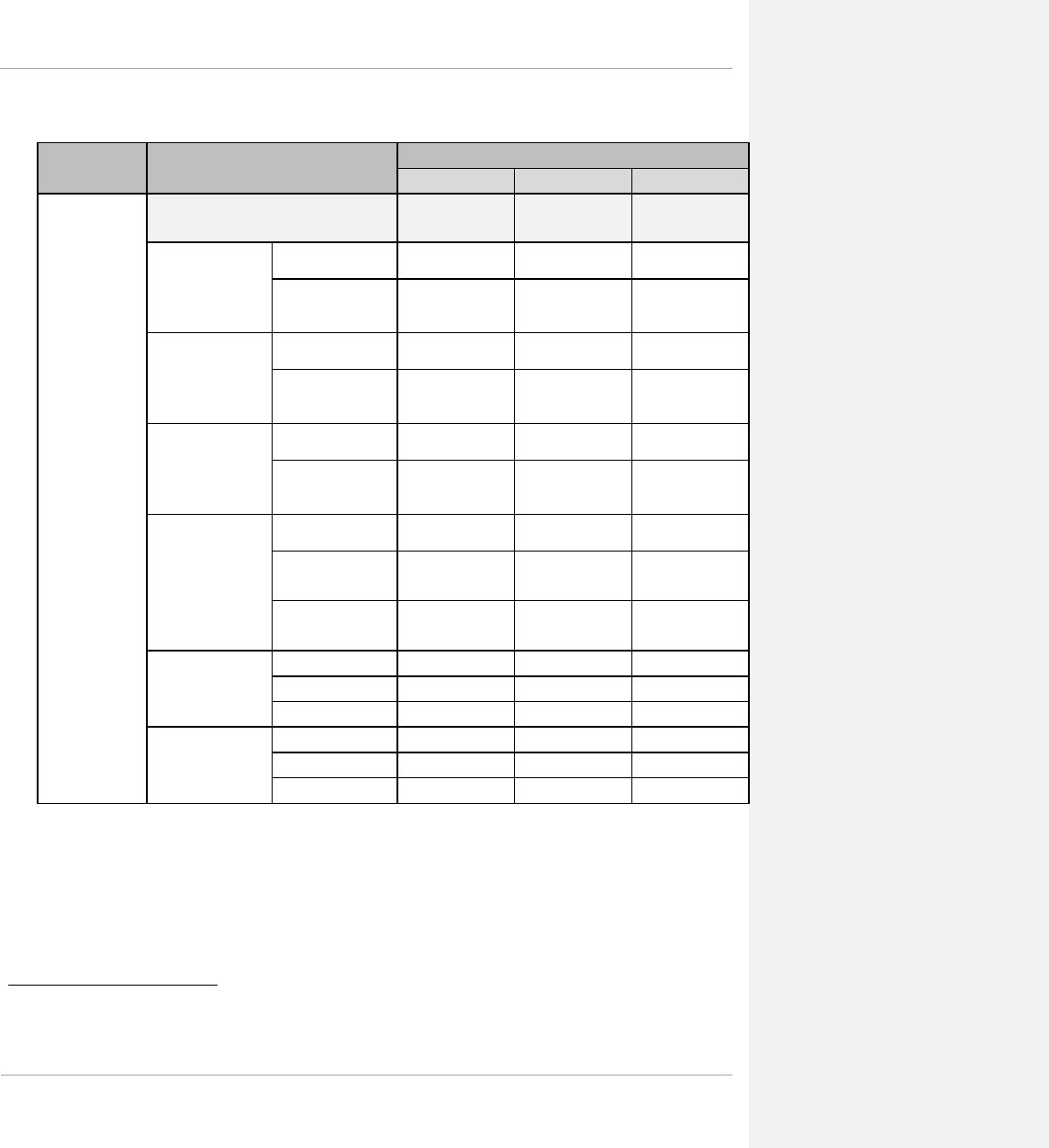
PMP 450 Planning Guide
Table 16 Link Budget Details – Dynamic Rate Adapt, 5.8GHz PMP 450 AP and PMP 430 SM
Product Parameter
Performance Details
1x
2x
3x
PMP 450 AP‡‡‡‡
PMP 430 SM
Modulation QPSK-SISO 16-QAM-SISO 64-QAM-SISO
5.8GHz Max. LOS
Link Budget (no fade
margin) – 20 MHz
channel bandwidth
with Integrated SM
antenna 9.9 mi / 15.84 km 4.4 mi / 7.04 km 1.7 mi / 2.72 km
with Reflector Dish
that adds 14 dB to SM
Range 40 mi / 64 km 24.8 mi / 39.68 km 9.3 mi / 14.88 km
5.8GHz Max. LOS
Link Budget (no fade
margin) – 10 MHz
channel bandwidth
with Integrated SM
antenna 12.4 mi / 19.84 km 6.2 mi / 9.92 km 2.4 mi / 3.84 km
with Reflector Dish
that adds 14 dB to SM
Range 40 mi / 64 km 35 mi / 56 km 13.5 mi / 21.6 km
5.8GHz Max. LOS
Link Budget (no fade
margin) – 5 MHz
channel bandwidth
with Integrated SM
antenna 19.1 mi / 30.56 km 7.6 mi / 12.16 km 3 mi / 4.8 km
with Reflector Dish
that adds 14 dB to SM
Range 40 mi / 64 km 40 mi / 64 km 17 mi / 27.2 km
5.8GHz Max.
Aggregate Throughput
with 1/16 Cyclic Prefix
to 1 SM (75%/25%
DL/UL Ratio) – RF
Link Test
20 MHz Channel:
(up+down) 13 Mbps 28 Mbps 48 Mbps
10 MHz Channel:
(up+down) 6 Mbps 12 Mbps 20 Mbps
5 MHz Channel:
(up+down) 2 Mbps 4 Mbps 7 Mbps
5.8GHz Nominal Per-
Chain Receive SM RX
Sensitivity (including
FEC)§§§§
20 MHz Channel -87 dBm -80 dBm -74 dBm
10 MHz Channel -89 dBm -83 dBm -77 dBm
5 MHz Channel -94 dBm -87 dBm -80 dBm
Link Budget,
Integrated (dB)
20 MHz Channel 131.8 124.8 116.3
10 MHz Channel 133.8 127.8 119.5
5 MHz Channel 137.5 129.5 121.5
‡‡‡‡ Maximum setting of Max Range parameter is 40 mi.
§§§§ PMP 450 devices include a dual polar antenna; Channel A (Vertical) and Channel B (Horizontal). Listed receive
sensitivity corresponds to single-channel readings.
pmp-0047 (March 2014) 1-45

PMP 450 Planning Guide
Adaptive modulation
PMP 450 units can transport data over the wireless link using a number of different modulation modes. The radio
automatically selects QPSK (Quadrature Phase Shift Keying) - SISO, QPSK-MIMO, 16-QAM (Quadrature
Amplitude Modulation) - MIMO, 64-QAM - MIMO, or 256-QAM - MIMO based on the RF environment to
provide 1x, 2x, 4x, 6x and 8x operation.
MIMO
Multiple-Input Multiple-Output (MIMO) techniques provide protection against fading and increase the probability
that the receiver will decode a usable signal. When the effects of MIMO are combined with those of OFDM
techniques and a high link budget, there is a high probability of a robust connection over a non-line-of-sight path.
The sub-feature that comprises the MIMO technique utilized in the PMP 450 product is:
• Matrix B: This technique provides for the ability to double the throughput of a radio transmission under proper
RF conditions. Different data streams are transmitted simultaneously on two different antennas.
Cyclic Prefix
OFDM technology uses a cyclic prefix, where a portion of the end of a symbol (slot) is repeated at the beginning of
the symbol (slot) to allow multi-pathing to settle before receiving the desired data. A 1/16 cyclic prefix means that
for every 16 bits of throughput data transmitted, an additional bit is used.
Encryption
The Cambium PMP 450 Series supports optional encryption for data transmitted over the wireless link. The PMP
450 Series supports the following forms of encryption for security of the wireless link:
• DES (Data Encryption Standard): An over-the-air link encryption option that uses secret 56-bit keys and 8
parity bits. DES performs a series of bit permutations, substitutions, and recombination operations on blocks of
data. DES encryption does not affect the performance or throughput of the system.
• AES (Advanced Encryption Standard): An over-the-air link encryption option that uses the Rijndael
algorithm and 128-bit keys to establish a higher level of security than DES. AES products are certified as
compliant with the Federal Information Processing Standards (FIPS 197) in the U.S.A.
Further reading on wireless operation
For information on planning wireless operation, see the following:
• Regulatory planning on page 1-55 describes the regulatory restrictions that affect radio spectrum usage, such as
frequency range.
1-46 pmp-0047 (March 2014)

PMP 450 Planning Guide
System management
This section introduces the PMP 450 management system, including the web interface, installation, configuration,
alerts and upgrades, and management software.
Management agent
PMP 450 equipment is managed through an embedded management agent. Management workstations, network
management systems or PCs can be connected to this agent using the module’s Ethernet port or over-the air (SM).
The management agent supports the following interfaces:
• Hypertext transfer protocol (HTTP)
• RADIUS authentication
• Simple network management protocol (SNMP)
• Network time protocol (NTP)
• System logging (Syslog)
• Wireless Manager (WM) software
• Canopy Network Updater Tool (CNUT) software
Web server
The PMP 450 management agent contains a web server. The web server supports access via the HTTP interface..
Web-based management offers a convenient way to manage the PMP 450 equipment from a locally connected
computer or from a network management workstation connected through a management network, without requiring
any special management software. The web-based interfaces are the only interfaces supported for installation of
PMP 450, and for the majority of PMP 450 configuration management tasks.
pmp-0047 (March 2014) 1-47
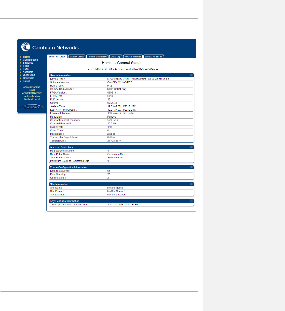

PMP 450 Planning Guide
Web pages
The web-based management interfaces provide comprehensive web-based fault, configuration, performance and
security management functions organized into the following web-pages and groups:
Access Point web-pages:
• Home: The Home web-page reports the general device status, session status, remote subscriber status, event
log information, network interface status, and layer 2 neighbor information.
• Configuration: The Configuration web-page may be utilized for configuring general device parameters, as
well as IP, radio, SNMP, Quality of Service (QoS), security, time, VLAN, DiffServ, protocol filtering, and unit
settings.
• Statistics: The Statistics web-page reports detailed operating statistics for the scheduler, SM registration
failures, bridge control block, bridging table, Ethernet, radio, VLAN, data VC, throughput, filter, ARP,
overload, DHCP relay, pass through, and DNS.
• Tools: The Tools web-page offers useful tools for device installation, configuration, and operation including
link capacity test, frame calculator, subscriber configuration, link status, remote spectrum analyzer, sessions,
and DNS test.
• Logs: The Logs web-page displays logs related to device operation including AP sessions, AP authentication
state machine, AP authorization state machine, and EAP Radius.
• Accounts: These web-pages are used to configure device user accounts.
• Quick Start: The Quick Start web-page provides a walkthrough of configuring radio parameters for initial
operation.
• Copyright: The Copyright web-page displays pertinent device copyright information.
Subscriber Module web-pages:
• Home: The Home web-page reports the general device status, event log information, network interface status,
and layer 2 neighbor information.
• Configuration: The Configuration web-page may be utilized for configuring general device parameters, as
well as IP, radio, SNMP, Quality of Service (QoS), security, VLAN, DiffServ, protocol filtering, NAT, PPPoE,
NAT port mapping, and unit settings.
• Statistics: The Statistics web-page reports detailed operating statistics for the scheduler, bridge control block,
bridging table, translation table, Ethernet, radio, VLAN, data VC, filter, NAT, NAT DHCP, ARP, overload,
PPPoE, peer information, and DNS.
• Tools: The Tools web-page offers useful tools for device installation, configuration, and operation including a
spectrum analyzer, alignment configuration and tool, link capacity test, AP evaluation, frame calculator, BER
results, link status, and DNS test.
• Logs: The Logs web-page displays logs related to device operation including the NAT table, SM session, SM
authentication, SM authorization, PPPoE session, and EAP Radius.
• Accounts: These web-pages are used to configure device user accounts.
• PDA: The PDA web-page includes 320 x 240 pixel formatted displays of information important to installation
and alignment for installers using legacy PDA devices. All device web pages are compatible with touch
devices such as smart phones and tablets.
• Copyright: The Copyright web-page displays pertinent device copyright information.
pmp-0047 (March 2014) 1-49

PMP 450 Planning Guide
Identity-based user accounts
When identity-based user accounts are configured, a security officer can define from one to four user accounts, each
of which may have one of the four possible roles:
• ADMINISTRATOR, who has full read and write permissions. This is the level of the root and admin users,
as well as any other administrator accounts that one of them creates.
• INSTALLER, who has permissions identical to those of ADMINISTRATOR except that the installer cannot
add or delete users or change the password of any other user.
• TECHNICIAN, who has permissions to modify basic radio parameters and view informational web pages
• GUEST, who has no write permissions and only a limited view of General Status tab
See Table 57 Identity-based user account permissions - AP on page 1-128 and Table 58 Identity-based user account
permissions - SM on page 1-130 for detailed information on account permissions.
Remote Authentication Dial In User Service (RADIUS)
The PMP 450 system includes support for RADIUS (Remote Authentication Dial In User Service) protocol
functionality including:
• Authentication: Allows only known SMs onto the network (blocking “rogue” SMs), and can be configured to
ensure SMs are connecting to a known network (preventing SMs from connecting to “rogue” APs). RADIUS
authentication is used for SMs, but not used for APs.
• SM Configuration: Configures authenticated SMs with MIR (Maximum Information Rate), High Priority, and
VLAN (Virtual LAN) parameters from the RADIUS server when an SM registers to an AP.
• SM Accounting provides support for RADIUS accounting messages for usage-based billing. This accounting
includes indications for subscriber session establishment, subscriber session disconnection, and bandwidth
usage per session for each SM that connects to the AP.
• Centralized AP and SM user name and password management: Allows AP and SM usernames and access
levels (Administrator, Installer, Technician) to be centrally administered in the RADIUS server instead of on
each radio and tracks access events (logon/logoff) for each username on the RADIUS server. This accounting
does not track and report specific configuration actions performed on radios or pull statistics such as bit counts
from the radios. Such functions require an Element Management System (EMS) such as Cambium Wireless
Manager. This accounting is not the ability to perform accounting functions on the subscriber/end
user/customer account.
• Framed-IP-Address: Operators may use a RADIUS server to assign management IP addressing to SM
modules.
SNMP
• The management agent supports fault and performance management by means of an SNMP interface. The
management agent is compatible with SNMP v1 and SNMP v2c using 5 Management Information Base (MIB)
files which are available for download from the Cambium Networks Support website
(https://support.cambiumnetworks.com/files/pmp450).
1-50 pmp-0047 (March 2014)

PMP 450 Planning Guide
Network Time Protocol (NTP)
The clock supplies accurate date and time information to the system. It can be set to run with or without a
connection to a network time server (NTP). It can be configured to display local time by setting the time zone and
daylight saving in the Time web page.
If an NTP server connection is available, the clock can be set to synchronize with the server time at regular
intervals.
PMP 450 devices may receive NTP data from a CMM3 or CMM4 module, an NTP server configured in the
system’s management network or a UGPS module.
The Time Zone option is configurable on the AP’s Time Configuration page, and may be used to offset the received
NTP time to match the operator’s local time zone. When set on the AP, the offset will be set for the entire sector
(SMs will be notified of the current Time Zone upon initial registration). If a Time Zone change is applied, the
SMs will be notified of the change in a best effort fashion, meaning some SMs may not pick up the change until the
next re-registration. Time Zone changes are noted in the Event Log of the AP and SM.
An AP which is receiving NTP date and time information from an NTP server or from a GPS synchronization
source may be used as an NTP server. Any client which has IP connectivity to the AP may request NTP date and
time information from the AP. No additional configuration (other than the AP receiving valid NTP data) is required
to use the AP as an NTP server.
Wireless Manager (WM)
Cambium Networks Wireless Manager 4.0 is recommended for managing PMP 450 networks. You can achieve
better uptime through better visibility of your network with the Cambium Wireless Manager. This network
management software tool offers breakthrough map-based visualization capabilities using embedded Google maps,
and combined with advanced configuration, provisioning, alerting and reporting features you can control your entire
outdoor wireless network including Mesh Wide Area Network, and Point-to-Multipoint and Point-to-Point solutions
as well as other SNMP enabled devices. With its powerful user interface you will not only be able to control your
network's access, distribution and backhaul layers, but you will also have visibility to WLAN sites and be able to
quickly launch indoor network management systems.
Some key features of Wireless Manager are:
• Template-Based Configuration: With Wireless Manager's user-defined templates you can accelerate the
process for the configuration of the devices you add to your network resulting in quicker and easier
deployments. The template-based functionality provides an automated way to configure large numbers of
network devices with just a few mouse clicks, and can be scheduled to occur at any time via Wireless
Manager's Task Scheduler.
• Ultralight Thin Client: With the growing mobile workforce it is important to have access to the status of your
network at any time. With Wireless Manager you can view the status and performance of your entire wireless
network via a compact web interface accessible by your smart phone.
• Map-Based Visualization: Wireless Manager overlays sophisticated real-time information about your network
elements onto building layouts and dynamic Google maps. Visuals can be scaled to view an entire city or
building or a specific area, floor or link.
pmp-0047 (March 2014) 1-51

PMP 450 Planning Guide
• High Availability Architecture Support: Wireless Manager offers a high availability option, providing a
highly reliable and redundant network management solution that ensures you always have management access
to your network.
• High Scalability: The enhanced Wireless Manager offers you server scalability with support for up to 10,000
nodes as well as support for distributed server architecture.
Cambium’s Wireless Manager 4.0 available for download at:
http://www.cambiumnetworks.com/support/management-tools/wireless-manager/
Canopy Network Updater Tool (CNUT)
CNUT (Canopy Network Updater Tool) is the stand-alone software update tool for PMP 450 Series products.
The Canopy Network Updater Tool:
• automatically discovers all network elements
• executes a UDP command that initiates and terminates the Auto-update mode within APs. This command is
both secure and convenient:
o For security, the AP accepts this command from only the IP address that you specify in the Configuration
page of the AP.
o For convenience, Network Updater automatically sets this Configuration parameter in the APs to the IP
address of the Network Updater server when the server performs any of the update commands.
• allows you to choose among updating
o your entire network.
o only elements that you select.
o only network branches that you select.
• provides a Script Engine that you can use with any script that
o you define.
o Cambium supplies.
CNUT is available at http://www.cambiumnetworks.com/support/management-tools/cnut/
Capacity upgrades
Capacity upgrades are supplied as an access key purchased from your Cambium Point-to-Multipoint distributor or
solutions provider. The upgrade is applied by entering the supplied URL in a PMP 450 module-connected web
browser address bar.
Software upgrade
CNUT (Canopy Network Updater Tool) is the stand-alone software update tool for PMP 450 Series products.
CNUT is available at http://www.cambiumnetworks.com/support/management-tools/cnut/
1-52 pmp-0047 (March 2014)


PMP 450 Planning Guide
Chapter 1: Planning considerations
This chapter provides information to help the user to plan a PMP 450 network.
The following topics are described in this chapter:
• Regulatory planning on page 1-55 describes how to plan PMP 450 links to conform to the regulatory
restrictions that apply in the country of operation.
• Network migration planning on page 1-56 presents migration scenarios to aid in planning a network
deployment
• Site planning on page 1-65 describes factors to be considered when choosing sites for the equipment
• Link planning on page 1-66 describes factors to be taken into account when planning links, such as range, path
loss and throughput.
• Analyzing the RF Environment on page 1-94 describes how to map RF neighbor frequencies, anticipate
reflection, assess RF obstructions in the Fresnel Zone, and plan channel usage.
• Selecting Sites for Network Elements on page 1-102 describes how to survey sites, find expected coverage
areas, clear the radio horizon, and calculate aim angles.
• Diagramming Network Layouts on page 1-105 includes tips on how to avoid self-interference as well as
interference from external sources.
• Grounding and lightning protection on page 1-107 discusses wiring standards, the need for surge protection,
lightning protection zones, and general protection requirements.
• Configuration options for TDD synchronization on page 1-115 covers the importance of GPS synchronization
as well as planning for installation
• Data network planning on page 1-119 discusses IP networking and other networking features provided with the
PMP 450 product
• Security planning on page 1-127 can be referenced for information regarding security features of the product.
1-54 pmp-0047 (March 2014)
PMP 450 Planning Guide
Regulatory planning
This section describes how to plan PMP 450 links to conform to the regulatory restrictions that apply in the country
of operation.
It is the responsibility of the user to ensure that the PMP product is operated in accordance with local regulatory
limits.
Contact the applicable radio regulator to find out whether or not registration of the PMP network is required.
Obeying Regulatory limits
The local regulator may restrict frequency usage and channel width, and may limit the amount of conducted or
radiated transmitter power. Some countries impose conducted power limits on products operating in the 2.4 GHz,
3.5GHz, 3.6GHz, 5.4 GHz and 5.8 GHz bands. For detailed information, see Compliance with radio regulations on
page 3-17.
Conforming to the limits
Ensure the system is configured to conform to local regulatory requirements by setting the appropriate Country
Code setting on the APs and SMs in the network. When using connectorized APs with external antennas, the
regulations may require the maximum transmit power to be reduced. To ensure that regulatory requirements are met
for connectorized installations, see Calculating maximum power level for connectorized AP units on page 1-92.
pmp-0047 (March 2014) 1-55

PMP 450 Planning Guide
Network migration planning
The PMP 450 Series offers current network operators the ability to migrate to PMP 450 for expanded network
capacity and capability. The following sections are provided to aid in establishing a planning framework for
deploying a PMP 450 system.
Example PMP 450 deployment scenario
The following sections detail example network deployment scenarios for the PMP 450 product. This table may be
referenced to begin planning the PMP 450 deployment based on the current network configuration (if applicable).
Definitions of deployment scenario terminology
Table 17 Deployment scenario terminology descriptions
Term Definition
Existing System Release The current running system software release
Existing Number of Sectors The total number of AP sectors co-located in the current system
Existing Modulation
The type of modulation used in the current network. “FSK”
indicates an existing PMP 1x0 series network, and “OFDM”
indicates an existing PMP 430 network.
Existing Frequency Re-use Pattern
The current deployment’s usage of frequency across tower
sectors. For example, in a six AP sector deployment, the
following represents an ABC frequency re-use pattern.
• Sector 1 (A): 5740
• Sector 2 (B): 5760
• Sector 3 (C): 5780
• Sector 4 (A): 5740
• Sector 5 (B): 5760
• Sector 6 (C): 5780
The deployment scenarios define their own customized examples
of frequency re-use patterns.
For multiple AP cluster deployments, see Multiple OFDM Access
Point Clusters on page 1-97
Existing Ch BW (MHz)
The channel size, or channel bandwidth used in the current
system. For FSK (PMP 1x0 series) deployments, the channel
bandwidth is always 20 MHz (except 900 MHz FSK, which
operate with 8 MHz channel bandwidth). For OFDM (PMP 430)
deployments, the channel size may be 5, 10, or 20 MHz.
1-56 pmp-0047 (March 2014)

PMP 450 Planning Guide
Term Definition
Existing Total Bandwidth Used (MHz) The total amount of spectrum, in MHz, which is used by the
existing system.
Existing Aggregate Tower Throughput
(Mbps)
The total amount of throughput, in Mbps, available in the current
network deployment.
Existing Additional Frequencies Available
(MHz)
The number of additional frequencies unused by the current
deployment that are available for usage by PMP 450 equipment.
FINAL: Aggregate Throughput (Mbps) The aggregate throughput available after upgrading to a PMP 450
network.
Resulting Number of Sectors The number of sectors configured in the new PMP 450 network
installation.
Resulting Modulation The modulation scheme utilized in the new PMP 450 network
installation.
Resulting Frequency Re-use Pattern
The new frequency re-use pattern utilized in the new PMP 450
network installation. Each deployment scenario in this section
includes a custom example of a frequency re-use plan.
Resulting Ch BW (MHz) The resulting channel bandwidth configured in the PMP 450
system.
Resulting Total Bandwidth Used (MHz) The total amount of spectrum which is used by the existing
system.
Resulting Aggregate Tower Throughput
(Mbps)
The aggregate throughput available after upgrading to a PMP 450
network.
Resulting Percentage Increase in
Aggregate Tower Throughput
The amount of increase in tower (all sectors) throughput after
upgrading to a PMP 450 network.
Total Bandwidth Used (During
Migration) (MHz)
The total amount of spectrum (in MHz) used when migrating to a
PMP 450 deployments.
pmp-0047 (March 2014) 1-57

PMP 450 Planning Guide
Sector capacity
The following table exhibits the maximum aggregate sector throughput for several Cambium network deployments.
This table may be used as a reference for planning new networks or for planning network upgrades.
Table 18 Examples of aggregate sector throughput – FSK (PMP 1x0 Series)
Air Interface Rate
Adapt Ch BW
(MHz) Cyclic
Prefix Maximum Aggregate
Sector Throughput -
RF Link Test (Mbps)
FSK (PMP 1x0 Series – 900 MHz) 1x 8 N/A 2.4
FSK (PMP 1x0 Series – 900 MHz) 2x 8 N/A 4.8
FSK (PMP 1x0 Series) 1x 20 N/A 7
FSK (PMP 1x0 Series) 2x 20 N/A 14
Table 19 Examples of aggregate sector throughput – OFDM (PMP 430 Series)
Air Interface Rate
Adapt Ch BW
(MHz) Cyclic
Prefix Maximum Aggregate
Sector Throughput -
RF Link Test (Mbps)
OFDM (PMP 430 Series) 1x 5 CP 1/16 3.5
OFDM (PMP 430 Series) 2x 5 CP 1/16 7
OFDM (PMP 430 Series) 3x 5 CP 1/16 10.5
OFDM (PMP 430 Series) 1x 10 CP 1/16 7.5
OFDM (PMP 430 Series) 2x 10 CP 1/16 15
OFDM (PMP 430 Series) 3x 10 CP 1/16 22.5
OFDM (PMP 430 Series) 1x 20 CP 1/16 16.5
OFDM (PMP 430 Series) 2x 20 CP 1/16 32
OFDM (PMP 430 Series) 3x 20 CP 1/16 45+
1-58 pmp-0047 (March 2014)

PMP 450 Planning Guide
Table 20 Examples of aggregate sector throughput – OFDM MIMO (PMP 450 Series)
Air Interface Rate
Adapt Ch BW
(MHz) Cyclic
Prefix Maximum Aggregate
Sector Throughput -
RF Link Test (Mbps)
OFDM (SISO) (PMP 450 Series) 1x 5 CP 1/16 2
OFDM (MIMO) (PMP 450 Series) 2x 5 CP 1/16 4
OFDM (MIMO) (PMP 450 Series) 4x 5 CP 1/16 8
OFDM (MIMO) (PMP 450 Series) 6x 5 CP 1/16 14
OFDM (MIMO) (PMP 450 Series) 8x 5 CP 1/16 18
OFDM (SISO) (PMP 450 Series) 1x 10 CP 1/16 6
OFDM (MIMO) (PMP 450 Series) 2x 10 CP 1/16 13
OFDM (MIMO) (PMP 450 Series) 4x 10 CP 1/16 26
OFDM (MIMO) (PMP 450 Series) 6x 10 CP 1/16 42
OFDM (MIMO) (PMP 450 Series) 8x 10 CP 1/16 55
OFDM (SISO) (PMP 450 Series) 1x 20 CP 1/16 13
OFDM (MIMO) (PMP 450 Series) 2x 20 CP 1/16 30
OFDM (MIMO) (PMP 450 Series) 4x 20 CP 1/16 60
OFDM (MIMO) (PMP 450 Series) 6x 20 CP 1/16 98
OFDM (MIMO) (PMP 450 Series) 8x 20 CP 1/16 128
pmp-0047 (March 2014) 1-59
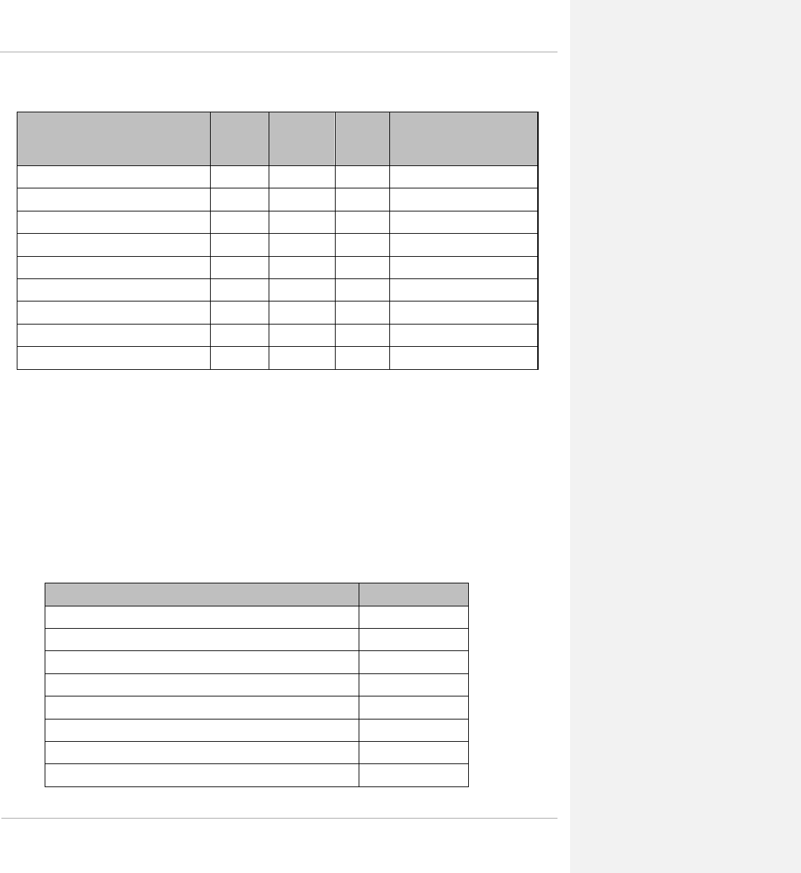
PMP 450 Planning Guide
Table 21 Examples of aggregate sector throughput – PMP 450 AP to PMP 430 SM
Air Interface Rate
Adapt Ch BW
(MHz) Cyclic
Prefix Maximum Aggregate
Sector Throughput -
RF Link Test (Mbps)
OFDM (PMP 450 AP to PMP 430 SM) 1x 5 CP 1/16 2
OFDM (PMP 450 AP to PMP 430 SM) 2x 5 CP 1/16 4
OFDM (PMP 450 AP to PMP 430 SM) 3x 5 CP 1/16 7
OFDM (PMP 450 AP to PMP 430 SM) 1x 10 CP 1/16 6
OFDM (PMP 450 AP to PMP 430 SM) 2x 10 CP 1/16 12
OFDM (PMP 450 AP to PMP 430 SM) 3x 10 CP 1/16 20
OFDM (PMP 450 AP to PMP 430 SM) 1x 20 CP 1/16 13
OFDM (PMP 450 AP to PMP 430 SM) 2x 20 CP 1/16 28
OFDM (PMP 450 AP to PMP 430 SM) 3x 20 CP 1/16 48
Deployment scenario 1 – Replacing PMP 100 Equipment (20 MHz
Channel Bandwidth)
Deployment scenario 1 assumes that the existing network comprises of PMP 1x0 equipment (i.e. PMP 100, PMP
120, etc.) with the configuration listed below in Table 22. The migration in this scenario results in a complete
replacement of PMP 1x0 series equipment with PMP 450 equipment.
Scenario 1 assumes that neighbouring frequencies are free and that a guard band is not required at the edges of the
spectrum used for transmission.
Table 22 Deployment scenario 1
Term Definition
Existing System Release 12.1
Existing Number of Sectors 6
Existing Modulation FSK
Existing Frequency Re-use Pattern ABC ABC
Existing Ch BW (MHz) 20
Existing Aggregate Tower Throughput (Mbps) 84
Existing Total Bandwidth Used (MHz) 60
Existing Additional Frequencies Available (MHz) 10
1-60 pmp-0047 (March 2014)
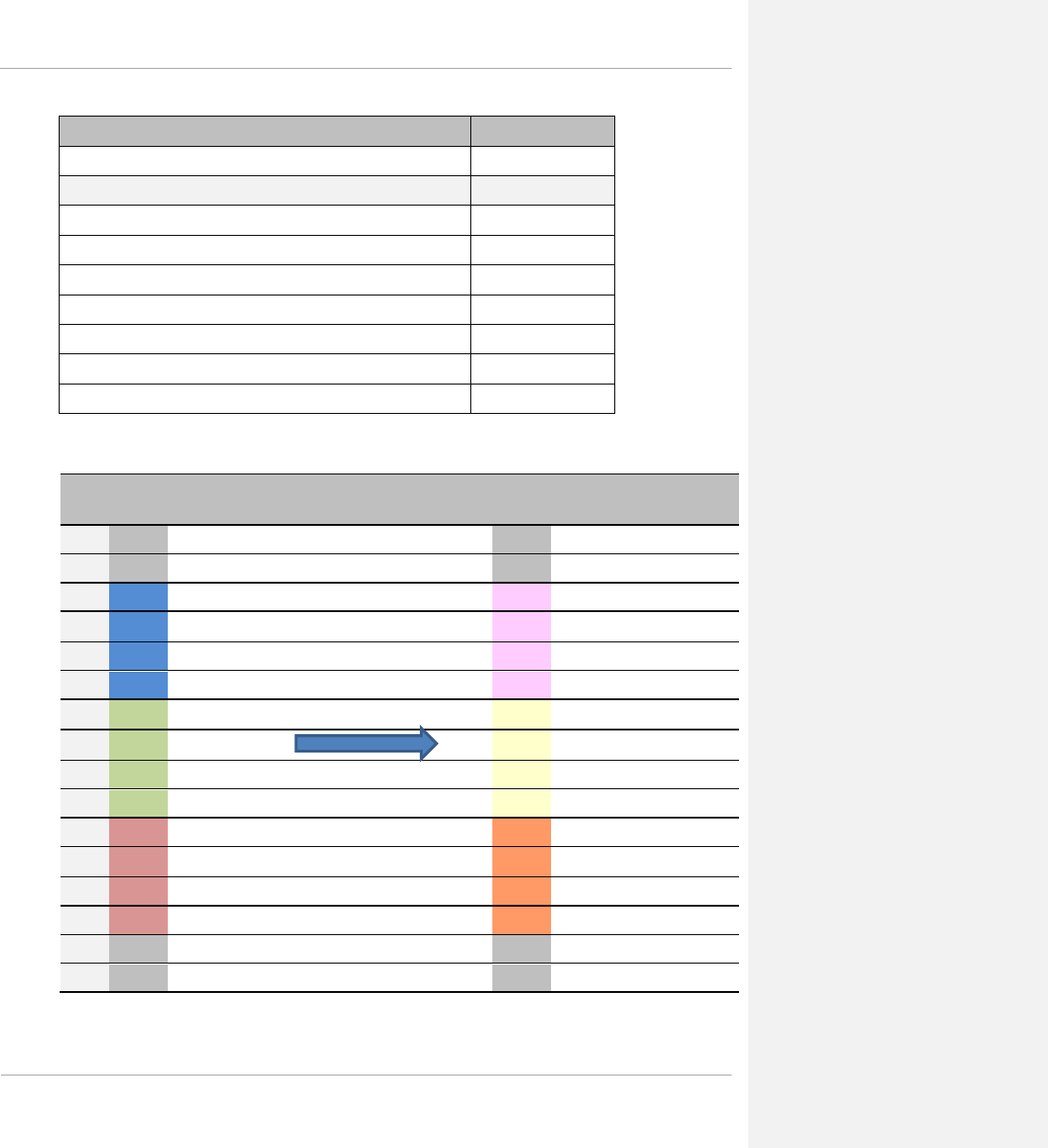
PMP 450 Planning Guide
Term Definition
Replace Legacy Subscribers with 450 SMs Required
Resulting Number of Sectors 6
Resulting Modulation OFDM (MIMO)
Resulting Frequency Re-use Pattern ABC ABC
Resulting Ch BW (MHz) 20
Resulting Total Bandwidth Used (MHz) 60
Resulting Aggregate Tower Throughput (Mbps) 570
Resulting Percentage Increase in Aggregate Tower Throughput 679%
Table 23 Scenario 1 spectrum usage
Beginning
frequency usage
Resulting frequency usage (assuming
no interference at band edges)
5725
5730
5735
5740
FSK (A)
MIMO (A) 5.740 GHz
5745
5750
5755
5760
FSK (B)
MIMO (B) 5.760 GHz
5765
5770
5775
5780
FSK (C)
MIMO (C) 5.780 GHz
5785
5790
5795
5800
pmp-0047 (March 2014) 1-61

PMP 450 Planning Guide
Deployment scenario 1 migration procedure
This procedure assumes that there are no temporary frequencies available and that the PMP 450 APs will replace
the existing APs.
Procedure 1a Deployment scenario 1 migration procedure
1 Identify proximity to potential system interferers by running a spectrum analysis scan where the PMP
450 equipment will be deployed. It is recommended to run this scan at several different times of day
and night
2 Record relevant AP and SM configuration parameters within the current operating network, if
applicable, including:
• authentication, and authorization parameters
• frequency configuration
• data network configuration
• RF statistics
• security configuration
3 Configure the PMP 450 AP and SMs for deployment
4 Install the PMP 450 AP
5 Install the PMP 450 MIMO(frequency A) SMs – powered on
6 Verify SM registration, link quality, and link performance.
7 Continue installation for frequency B sector and frequency C sector.
1-62 pmp-0047 (March 2014)

PMP 450 Planning Guide
Deployment scenario 2 – Replacing PMP 430 equipment (10 MHz
Channel Bandwidth)
Deployment scenario 2 assumes that the existing network is comprised of PMP 430 equipment with the
configuration listed below in Table 24. The migration in this scenario results in a complete replacement of PMP
430 series equipment with PMP 450 equipment.
Table 24 Deployment scenario 2
Term Definition
Existing System Release 12.2.2
Existing Number of Sectors 6
Existing Modulation OFDM
Existing Frequency Re-use Pattern ABC ABC
Existing Ch BW (MHz) 10
Existing Aggregate Tower Throughput (Mbps) 135
Existing Total Bandwidth Used (MHz) 30
Existing Additional Frequencies Available (MHz) 0
Replace Legacy Subscribers with 450 SMs Optional (PMP 430 Interop enables
PMP 430 SMs to register to PMP
450 AP)
Resulting Number of Sectors 6
Resulting Modulation OFDM (MIMO)
Resulting Frequency Re-use Pattern ABC ABC
Resulting Ch BW (MHz) 10
Resulting Total Bandwidth Used (MHz) 30
Resulting Aggregate Tower Throughput (Mbps) 234
Resulting Percentage Increase in Aggregate Tower Throughput 173%
pmp-0047 (March 2014) 1-63
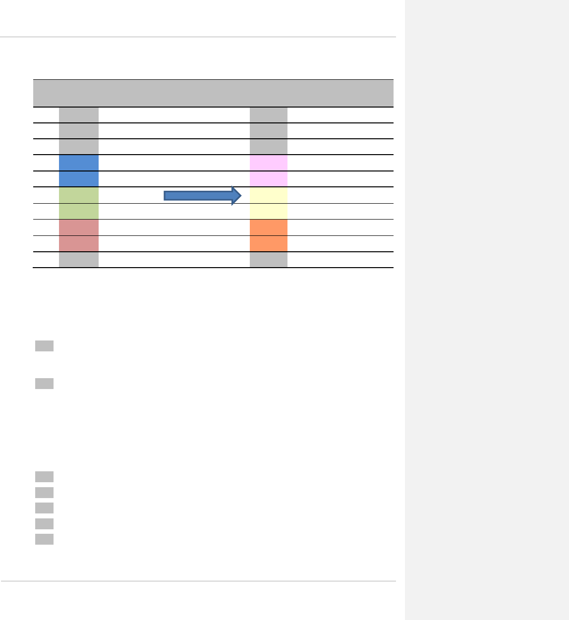
PMP 450 Planning Guide
Table 25 Deployment scenario 2 spectrum usage
Beginning PMP 430
frequency usage
Resulting PMP 450 frequency usage
5725
5730
5735
5740
OFDM (A)
MIMO (A) 5.740 GHz
5745
5750
OFDM (B)
MIMO (B) 5.750 GHz
5755
5760
OFDM (C)
MIMO (C) 5.760 GHz
5765
5770
Deployment scenario 2 migration procedure
This procedure assumes that there are no temporary frequencies available and that the PMP 450 APs will replace
the existing APs.
Procedure 2 Deployment scenario 2 migration procedure
1 Identify proximity to potential system interferers by running a spectrum analysis scan where the PMP
450 equipment will be deployed. It is recommended to run this scan at several different times of day
and night
2 Record relevant AP and SM configuration parameters within the current operating network, if
applicable, including:
• authentication, and authorization parameters
• frequency configuration
• data network configuration
• RF statistics
• security configuration
3 Configure the PMP 450 AP and SMs for deployment
4 Install the PMP 450 AP (frequency A)
5 Install the PMP 450 MIMO (frequency A) SMs – powered on
6 Verify SM registration, link quality, and link performance.
7 Continue installation for frequency B sector and frequency C sector.
1-64 pmp-0047 (March 2014)

PMP 450 Planning Guide
Site planning
This section describes factors to be taken into account when choosing sites for the AP or SM, power supplies,
CMM4 (if applicable) and GPS antenna (if applicable).
AP or SM site selection
When selecting a site for the AP or SM, consider the following factors:
• Height and location to ensure that people are kept away from the antenna; see Calculated distances and power
compliance margins on page 3-14.
• Height and location to achieve the best radio path.
• Ability to meet the requirements specified in Grounding and lightning protection on page 1-107.
• Aesthetics and planning permission issues.
• Cable lengths; see Maximum cable lengths on page 1-65.
• The effect of strong winds on the installation; see Wind loading on page 1-66.
Power supply site selection
When selecting a site for the AP or SM power supply, consider the following factors:
• Indoor location with no possibility of condensation.
• Availability of a mains electricity supply.
• Accessibility for viewing status indicator LED and connecting Ethernet cables.
• Cable lengths; see Maximum cable lengths on page 1-65.
Maximum cable lengths
When installing PMP 450 Series APs or SMs, the maximum permitted length of the shielded copper Ethernet
interface cable is 330 feet (100m) from AP/SM to their associated power supplies or CMM4.
When receiving synchronization signalling from a UGPS module, see table below for maximum synchronization
cable lengths.
Table 26 Sync cable length specification
Configuration Maximum Cable
Length (feet) Maximum Cable
Length (meters)
UGPS powered via external power source 330 100
UGPS powered via PMP 450 AP (via AP sync
port)
130 40
pmp-0047 (March 2014) 1-65

PMP 450 Planning Guide
Wind loading
Ensure that the site will not be prone to excessive wind loading.
Antennas and equipment mounted on towers or buildings will subject the mounting structure to significant lateral
forces when there is appreciable wind. Antennas are normally specified by the amount of force (in pounds) for
specific wind strengths. The magnitude of the force depends on both the wind strength and size of the antenna.
Calculation of lateral force (metric)
The magnitude of the lateral force can be estimated from:
Force (in kilograms) = 0.1045aV2
Where: Is:
a surface area in square meters
V wind speed in meters per second
The lateral force produced by a single PMP 450 at different wind speeds is shown in Table 27 Lateral force - metric
and Table 28 Lateral force - US.
Table 27 Lateral force - metric
Largest
surface area (square meters) Lateral force (Kg) at wind speed
(meters per second)
30 40 50 60 70
.066 (AP – 5 GHz, 60 Degree Sector) 6 11 17 25 34
.083 (AP – 5 GHz, 90 Degree Sector) 8 14 22 31 43
.27 (AP – 2.4 GHz, 60 Degree Sector) 25 45 71 102 138
.088 (AP – 3.5 GHz, 90 Degree Sector) 8 14 22 33 45
.088 (AP – 3.6 GHz, 90 Degree Sector) 8 14 22 33 45
.0027 (SM) 0.25 0.45 0.7 1 1.4
1-66 pmp-0047 (March 2014)

PMP 450 Planning Guide
Calculation of lateral force (US)
The magnitude of the lateral force can be estimated from:
Force (in pounds) = 0.0042Av2
Where: Is:
A surface area in square feet
v wind speed in miles per hour
The lateral force produced by a single PMP 450 unit at different wind speeds is shown in Table 28.
Table 28 Lateral force - US
Largest surface area (square
feet) Lateral force (lb) at wind speed
(miles per hour)
80 100 120 140 150
0.71 (AP – 5 GHz, 60 Degree Sector) 19 30 43 58 67
0.89 (AP – 5 GHz, 90 Degree Sector) 24 37 54 73 84
2.9 (AP – 2.4 GHz, 60 Degree Sector) 78 122 175 239 274
0.94 (AP – 3.5 GHz, 90 Degree Sector) 25 40 57 77 89
0.94 (AP – 3.6 GHz, 90 Degree Sector) 25 40 57 77 89
0.29 (SM) 7.8 12 18 23 27
Capabilities of the PMP 450 Series
The structure and mounting brackets of the AP are capable of withstanding wind speeds up to:
• 190 kph (118 mph) – 5 GHz Sector Antennas
• 216 kph (135 mph) – 2.4 GHz, 3.5 GHz, 3.6 GHz Sector Antennas
Ensure that the structure to which the AP is fixed to is also capable of withstanding the prevalent wind speeds and
loads.
The structure and mounting brackets of the SM are capable of withstanding wind speeds up to 190 kph (118 mph).
Ensure that the structure to which the SM is fixed to is also capable of withstanding the prevalent wind speeds and
loads.
pmp-0047 (March 2014) 1-67

PMP 450 Planning Guide
Wind speed statistics
Contact the national meteorological office for the country concerned to identify the likely wind speeds prevalent at
the proposed location. Use this data to estimate the total wind loading on the support structures. Sources of
information:
• US National Weather Service, http://www.nws.noaa.gov/
• UK Meteorological Office, www.meto.gov.uk
1-68 pmp-0047 (March 2014)

PMP 450 Planning Guide
Link planning
This section describes factors to be taken into account when planning links, such as range, obstacles, path loss and
throughput.
Range and obstacles
Calculate the range of the link and identify any obstacles that may affect radio performance.
Perform a survey to identify all the obstructions (such as trees or buildings) in the path and to assess the risk of
interference. This information is necessary in order to achieve an accurate link feasibility assessment.
The PMP 450 Series is designed to operate in Near-Line-of-Sight (nLOS), Non-Line-of-Sight (NLOS) and Line-of-
Sight (LOS) environments. An NLOS environment is one in which there is no optical line-of-sight, that is, there are
obstructions between the antennas. See Figure 1 Line Of Sight Diagram.
OFDM technology can often use multi-pathing to an advantage to overcome nLOS, especially in cases where the
Fresnel zone is only partially blocked by buildings, “urban canyons”, or foliage. OFDM tends to help especially
when obstacles are near the middle of the link, and less so when the obstacles are very near the SM or AP.
However, attenuation through walls and trees is substantial for any use of the 2.4 GHz, 3.5 GHz, 3.6 GHz, 5.4 GHz,
and 5.8 GHz frequency bands. Even with OFDM, these products should not be expected to penetrate walls or
extensive trees and foliage.
pmp-0047 (March 2014) 1-69

PMP 450 Planning Guide
Table 29 Link budget details – 5.8 GHz PMP 450 link, 20 MHz Channel Bandwidth
Product Parameter
Range Details
1x
2x
4x
6x
8x
PMP 450
Modulation QPSK-SISO QPSK-MIMO-B 16QAM-MIMO-B 64QAM-MIMO-B
256QAM-
MIMO-B
5.8GHz Max.
LOS Link
Budget (no fade
margin)
with Integrated
SM antenna 8.5 mi / 13.6 km 6 mi / 9.6 km 2.7 mi / 4.32 km 1.1 mi / 1.76 km 0.3 mi / 0.48 km
with CLIP that
adds 8 dB to SM
Range
24.1 mi / 38.56
km 17 mi / 27.2 km 7.7 mi / 12.32 km 3.1 mi / 4.96 km 1 mi / 1.6 km
with LENS that
adds 5.5 dB to
SM Range
15.2 mi / 24.32
km 10.8 mi / 17.28
km 4.9 mi / 7.84 km 2 mi / 3.2 km 0.6 mi / 0.96 km
with Reflector
Dish that adds 14
dB to SM Range 40 mi / 64 km 30.3 mi / 48.48
km 13.7 mi / 21.92 km 5.6 mi / 8.96 km 1.7 mi / 2.72 km
5.8GHz Max.
nLOS Link
Budget
(additional 5 dB
link loss)
with Integrated
SM antenna 4.8 mi / 7.68 km 3.4 mi / 5.44 km 1.5 mi / 2.4 km 0.6 mi / 0.96 km 0.2 mi / 0.32 km
with CLIP that
adds 8 dB to SM
Range
13.5 mi / 21.6
km 9.6 mi / 15.36 km 4.3 mi / 6.88 km 1.8 mi / 2.88 km 0.5 mi / 0.8 km
with LENS that
adds 5.5 dB to
SM Range 8.5 mi / 13.6 km 6 mi / 9.6 km 2.7 mi / 4.32 km 1.1 mi / 1.76 km 0.3 mi / 0.48 km
with Reflector
Dish that adds 14
dB to SM Range
24.1 mi / 38.56
km 17 mi / 27.2 km 7.7 mi / 12.32 km 3.1 mi / 4.96 km 1 mi / 1.6 km
5.8GHz Max.
NLOS1 Link
Budget
(additional 15
dB link loss)
with Integrated
SM antenna 1.5 mi / 2.4 km 1.1 mi / 1.76 km 0.5 mi / 0.8 km 0.2 mi / 0.32 km 0.1 mi / 0.16 km
with CLIP that
adds 8 dB to SM
Range 4.3 mi / 6.88 km 3 mi / 4.8 km 1.4 mi / 2.24 km 0.6 mi / 0.96 km 0.2 mi / 0.32 km
with LENS that
adds 5.5 dB to
SM Range 2.7 mi / 4.32 km 1.9 mi / 3.04 km 0.9 mi / 1.44 km 0.4 mi / 0.64 km 0.1 mi / 0.16 km
with Reflector
Dish that adds 14
dB to SM Range
7.6 mi / 12.16
km 5.4 mi / 8.64 km 2.4 mi / 3.84 km 1 mi / 1.6 km 0.3 mi / 0.48 km
5.8GHz Max.
NLOS2 Link
Budget
(additional 25
dB link loss)
with Integrated
SM antenna 0.5 mi / 0.8 km 0.3 mi / 0.48 km 0.2 mi / 0.32 km 0.1 mi / 0.16 km 0.1 mi / 0.16 km
with CLIP that
adds 8 dB to SM
Range 1.4 mi / 2.24 km 1 mi / 1.6 km 0.4 mi / 0.64 km 0.2 mi / 0.32 km 0.1 mi / 0.16 km
with LENS that
adds 5.5 dB to
SM Range 0.9 mi / 1.44 km 0.6 mi / 0.96 km 0.3 mi / 0.48 km 0.1 mi / 0.16 km 0.1 mi / 0.16 km
with Reflector
Dish that adds 14
dB to SM Range 2.4 mi / 3.84 km 1.7 mi / 2.72 km 0.8 mi / 1.28 km 0.3 mi / 0.48 km 0.1 mi / 0.16 km
1-70 pmp-0047 (March 2014)

PMP 450 Planning Guide
Table 30 Link budget details – 5.8 GHz PMP 450 link, 10 MHz Channel Bandwidth
Product Parameter
Range Details
1x
2x
4x
6x
8x
PMP 450
Modulation QPSK-SISO QPSK-MIMO-B 16QAM-MIMO-B 64QAM-MIMO-B
256QAM-
MIMO-B
5.8GHz Max.
LOS Link
Budget (no
fade margin)
with Integrated
SM antenna
11.7 mi /
18.72 km 8.3 mi / 13.28 km 3.6 mi / 5.76 km 1.5 mi / 2.4 km
0.5 mi / 0.8
km
with CLIP that
adds 9 dB to SM
capability
32.9 mi /
52.64 km 23.3 mi / 37.28
km 10.3 mi / 16.48 km 4.1 mi / 6.56 km 1.3 mi / 2.08
km
with LENS that
adds 5 dB to SM
capability
20.7 mi /
33.12 km 14.7 mi / 23.52
km 6.5 mi / 10.4 km 2.6 mi / 4.16 km 0.8 mi / 1.28
km
with Reflector
Dish that adds 14
dB to SM
capability
40 mi / 64 km 40 mi / 64 km 18.3 mi / 29.28 km 7.3 mi / 11.68 km 2.3 mi / 3.68
km
5.8GHz Max.
nLOS Link
Budget
(additional 5
dB link loss)
with Integrated
SM antenna
6.6 mi / 10.56
km 4.6 mi / 7.36 km 2 mi / 3.2 km 0.8 mi / 1.28 km
0.3 mi / 0.48
km
with CLIP that
adds 9 dB to SM
capability
18.5 mi / 29.6
km 13.1 mi / 20.96
km 5.8 mi / 9.28 km 2.3 mi / 3.68 km 0.7 mi / 1.12
km
with LENS that
adds 5 dB to SM
capability
11.7 mi /
18.72 km 8.3 mi / 13.28 km 3.6 mi / 5.76 km 1.5 mi / 2.4 km 0.5 mi / 0.8
km
with Reflector
Dish that adds 14
dB to SM
capability
32.9 mi /
52.64 km 23.3 mi / 37.28
km 10.3 mi / 16.48 km 4.1 mi / 6.56 km 1.3 mi / 2.08
km
5.8GHz Max.
NLOS1 Link
Budget
(additional 15
dB link loss)
with Integrated
SM antenna
2.1 mi / 3.36
km 1.5 mi / 2.4 km 0.6 mi / 0.96 km 0.3 mi / 0.48 km
0.1 mi / 0.16
km
with CLIP that
adds 9 dB to SM
capability
5.8 mi / 9.28
km 4.1 mi / 6.56 km 1.8 mi / 2.88 km 0.7 mi / 1.12 km 0.2 mi / 0.32
km
with LENS that
adds 5 dB to SM
capability
3.7 mi / 5.92
km 2.6 mi / 4.16 km 1.2 mi / 1.92 km 0.5 mi / 0.8 km 0.1 mi / 0.16
km
with Reflector
Dish that adds 14
dB to SM
capability
10.4 mi /
16.64 km 7.4 mi / 11.84 km 3.2 mi / 5.12 km 1.3 mi / 2.08 km 0.4 mi / 0.64
km
5.8GHz Max.
NLOS2 Link
Budget
(additional 25
dB link loss)
with Integrated
SM antenna
0.7 mi / 1.12
km 0.5 mi / 0.8 km 0.2 mi / 0.32 km 0.1 mi / 0.16 km
0.1 mi / 0.16
km
with CLIP that
adds 9 dB to SM
capability
1.8 mi / 2.88
km 1.3 mi / 2.08 km 0.6 mi / 0.96 km 0.2 mi / 0.32 km 0.1 mi / 0.16
km
with LENS that
adds 5 dB to SM
capability
1.2 mi / 1.92
km 0.8 mi / 1.28 km 0.4 mi / 0.64 km 0.1 mi / 0.16 km 0.1 mi / 0.16
km
with Reflector
Dish that adds 14
dB to SM
capability
3.3 mi / 5.28
km 2.3 mi / 3.68 km 1 mi / 1.6 km 0.4 mi / 0.64 km 0.1 mi / 0.16
km
pmp-0047 (March 2014) 1-71


PMP 450 Planning Guide
Table 31 Link budget details – 5.8 GHz PMP 450 link, 5 MHz Channel Bandwidth
Product Parameter
Range Details
1x
2x
4x
6x
8x
PMP 450
Modulation QPSK-SISO QPSK-MIMO-B 16QAM-MIMO-B 64QAM-MIMO-B
256QAM-
MIMO-B
5.8GHz Max.
LOS Link
Budget (no
fade margin)
with Integrated
SM antenna
14.5 mi / 23.2
km
10.3 mi / 16.48
km 5.1 mi / 8.16 km 2.2 mi / 3.52 km 0.6 mi / 0.96 km
with CLIP that
adds 8 dB to
SM Range 40 mi / 64 km 28.9 mi / 46.24
km 14.3 mi / 22.88 km 6.3 mi / 10.08 km 1.7 mi / 2.72 km
with LENS that
adds 5.5 dB to
SM Range
25.8 mi / 41.28
km 18.3 mi / 29.28
km 9 mi / 14.4 km 4 mi / 6.4 km 1.1 mi / 1.76 km
with Reflector
Dish that adds
14 dB to SM
Range
40 mi / 64 km 40 mi / 64 km 25.5 mi / 40.8 km 11.3 mi / 18.08
km 3 mi / 4.8 km
5.8GHz Max.
nLOS Link
Budget
(additional 5
dB link loss)
with Integrated
SM antenna
8.2 mi / 13.12
km 5.8 mi / 9.28 km 2.9 mi / 4.64 km 1.3 mi / 2.08 km 0.3 mi / 0.48 km
with CLIP that
adds 8 dB to
SM Range 23 mi / 36.8 km 16.3 mi / 26.08
km 8.1 mi / 12.96 km 3.6 mi / 5.76 km 1 mi / 1.6 km
with LENS that
adds 5.5 dB to
SM Range
14.5 mi / 23.2
km 10.3 mi / 16.48
km 5.1 mi / 8.16 km 2.2 mi / 3.52 km 0.6 mi / 0.96 km
with Reflector
Dish that adds
14 dB to SM
Range
40 mi / 64 km 28.9 mi / 46.24
km 14.3 mi / 22.88 km 6.3 mi / 10.08 km 1.7 mi / 2.72 km
5.8GHz Max.
NLOS1 Link
Budget
(additional 15
dB link loss)
with Integrated
SM antenna 2.6 mi / 4.16 km 1.8 mi / 2.88 km 0.9 mi / 1.44 km 0.4 mi / 0.64 km 0.1 mi / 0.16 km
with CLIP that
adds 8 dB to
SM Range
7.3 mi / 11.68
km 5.1 mi / 8.16 km 2.6 mi / 4.16 km 1.1 mi / 1.76 km 0.3 mi / 0.48 km
with LENS that
adds 5.5 dB to
SM Range 4.6 mi / 7.36 km 3.2 mi / 5.12 km 1.6 mi / 2.56 km 0.7 mi / 1.12 km 0.2 mi / 0.32 km
with Reflector
Dish that adds
14 dB to SM
Range
12.9 mi / 20.64
km 9.2 mi / 14.72 km 4.5 mi / 7.2 km 2 mi / 3.2 km 0.5 mi / 0.8 km
5.8GHz Max.
NLOS2 Link
Budget
(additional 25
dB link loss)
with Integrated
SM antenna 0.8 mi / 1.28 km 0.6 mi / 0.96 km 0.3 mi / 0.48 km 0.1 mi / 0.16 km 0.1 mi / 0.16 km
with CLIP that
adds 8 dB to
SM Range 2.3 mi / 3.68 km 1.6 mi / 2.56 km 0.8 mi / 1.28 km 0.4 mi / 0.64 km 0.1 mi / 0.16 km
with LENS that
adds 5.5 dB to
SM Range 1.5 mi / 2.4 km 1 mi / 1.6 km 0.5 mi / 0.8 km 0.2 mi / 0.32 km 0.1 mi / 0.16 km
with Reflector
Dish that adds
14 dB to SM
Range
4.1 mi / 6.56 km 2.9 mi / 4.64 km 1.4 mi / 2.24 km 0.6 mi / 0.96 km 0.2 mi / 0.32 km
pmp-0047 (March 2014) 1-73

PMP 450 Planning Guide
Table 32 Link budget details – 5.4 GHz PMP 450 link, 20 MHz Channel Bandwidth
***** Transmit power complies with FCC regulatory requirements.
Product Parameter
Range Details
1x
2x
4x
6x
8x
PMP
450*****
Modulation QPSK-SISO QPSK-MIMO-B
16QAM-MIMO-
B
64QAM-MIMO-
B
256QAM-
MIMO-B
5.4GHz Max.
LOS Link
Budget (no fade
margin)
with Integrated SM
antenna
4.8 mi / 7.68
km 3.4 mi / 5.44 km 1.5 mi / 2.4 km 0.7 mi / 1.12 km 0.2 mi / 0.32 km
with CLIP that adds
8 dB to SM Range 8.2 mi / 13.12
km 5.8 mi / 9.28 km 2.6 mi / 4.16 km 1.2 mi / 1.92 km 0.5 mi / 0.8 km
with LENS that
adds 5 dB to SM
Range
8.2 mi / 13.12
km 5.8 mi / 9.28 km 2.6 mi / 4.16 km 1.2 mi / 1.92 km 0.3 mi / 0.48 km
with Reflector Dish
that adds 14 dB to
SM Range
8.2 mi / 13.12
km 5.8 mi / 9.28 km 2.6 mi / 4.16 km 1.2 mi / 1.92 km 0.5 mi / 0.8 km
5.4GHz Max.
nLOS Link
Budget
(additional 5 dB
link loss)
with Integrated SM
antenna
2.7 mi / 4.32
km 1.9 mi / 3.04 km 0.9 mi / 1.44 km 0.4 mi / 0.64 km 0.1 mi / 0.16 km
with CLIP that adds
8 dB to SM Range 4.6 mi / 7.36
km 3.3 mi / 5.28 km 1.5 mi / 2.4 km 0.6 mi / 0.96 km 0.3 mi / 0.48 km
with LENS that
adds 5 dB to SM
Range
4.6 mi / 7.36
km 3.3 mi / 5.28 km 1.5 mi / 2.4 km 0.6 mi / 0.96 km 0.2 mi / 0.32 km
with Reflector Dish
that adds 14 dB to
SM Range
4.6 mi / 7.36
km 3.3 mi / 5.28 km 1.5 mi / 2.4 km 0.6 mi / 0.96 km 0.3 mi / 0.48 km
5.4GHz Max.
NLOS1 Link
Budget
(additional 15
dB link loss)
with Integrated SM
antenna
0.9 mi / 1.44
km 0.6 mi / 0.96 km 0.3 mi / 0.48 km 0.1 mi / 0.16 km 0.1 mi / 0.16 km
with CLIP that adds
8 dB to SM Range 1.5 mi / 2.4
km 1 mi / 1.6 km 0.5 mi / 0.8 km 0.2 mi / 0.32 km 0.1 mi / 0.16 km
with LENS that
adds 5 dB to SM
Range
1.5 mi / 2.4
km 1 mi / 1.6 km 0.5 mi / 0.8 km 0.2 mi / 0.32 km 0.1 mi / 0.16 km
with Reflector Dish
that adds 14 dB to
SM Range
1.5 mi / 2.4
km 1 mi / 1.6 km 0.5 mi / 0.8 km 0.2 mi / 0.32 km 0.1 mi / 0.16 km
5.4GHz Max.
NLOS2 Link
Budget
(additional 25
dB link loss)
with Integrated SM
antenna
0.3 mi / 0.48
km 0.2 mi / 0.32 km 0.1 mi / 0.16 km 0.1 mi / 0.16 km 0.1 mi / 0.16 km
with CLIP that adds
8 dB to SM Range 0.5 mi / 0.8
km 0.3 mi / 0.48 km 0.1 mi / 0.16 km 0.1 mi / 0.16 km 0.1 mi / 0.16 km
with LENS that
adds 5 dB to SM
Range
0.5 mi / 0.8
km 0.3 mi / 0.48 km 0.1 mi / 0.16 km 0.1 mi / 0.16 km 0.1 mi / 0.16 km
with Reflector Dish
that adds 14 dB to
SM Range
0.5 mi / 0.8
km 0.3 mi / 0.48 km 0.1 mi / 0.16 km 0.1 mi / 0.16 km 0.1 mi / 0.16 km
1-74 pmp-0047 (March 2014)

PMP 450 Planning Guide
Table 33 Link budget details – 5.4 GHz PMP 450 link, 10 MHz Channel Bandwidth
††††† Transmit power complies with FCC regulatory requirements.
Product Parameter
Range Details
1x
2x
4x
6x
8x
PMP
450†††††
Modulation QPSK-SISO QPSK-MIMO-B
16QAM-MIMO-
B
64QAM-MIMO-
B
256QAM-
MIMO-B
5.4GHz Max.
LOS Link
Budget (no fade
margin)
with Integrated
SM antenna 4.3 mi / 6.88 km 3.1 mi / 4.96 km 1.6 mi / 2.56 km 0.7 mi / 1.12 km 0.2 mi / 0.32 km
with CLIP that
adds 8 dB to SM
Range 7.5 mi / 12 km 5.3 mi / 8.48 km 2.4 mi / 3.84 km 1.1 mi / 1.76 km 0.3 mi / 0.48 km
with LENS that
adds 5 dB to SM
Range 7.5 mi / 12 km 5.3 mi / 8.48 km 2.4 mi / 3.84 km 1.1 mi / 1.76 km 0.3 mi / 0.48 km
with Reflector
Dish that adds 14
dB to SM Range 7.5 mi / 12 km 5.3 mi / 8.48 km 2.4 mi / 3.84 km 1.1 mi / 1.76 km 0.3 mi / 0.48 km
5.4GHz Max.
nLOS Link
Budget
(additional 5 dB
link loss)
with Integrated
SM antenna 2.4 mi / 3.84 km 1.7 mi / 2.72 km 0.9 mi / 1.44 km 0.4 mi / 0.64 km 0.1 mi / 0.16 km
with CLIP that
adds 8 dB to SM
Range 4.2 mi / 6.72 km 3 mi / 4.8 km 1.4 mi / 2.24 km 0.6 mi / 0.96 km 0.2 mi / 0.32 km
with LENS that
adds 5 dB to SM
Range 4.2 mi / 6.72 km 3 mi / 4.8 km 1.4 mi / 2.24 km 0.6 mi / 0.96 km 0.2 mi / 0.32 km
with Reflector
Dish that adds 14
dB to SM Range 4.2 mi / 6.72 km 3 mi / 4.8 km 1.4 mi / 2.24 km 0.6 mi / 0.96 km 0.2 mi / 0.32 km
5.4GHz Max.
NLOS1 Link
Budget
(additional 15
dB link loss)
with Integrated
SM antenna 0.8 mi / 1.28 km 0.5 mi / 0.8 km 0.3 mi / 0.48 km 0.1 mi / 0.16 km 0.1 mi / 0.16 km
with CLIP that
adds 8 dB to SM
Range 1.3 mi / 2.08 km 0.9 mi / 1.44 km 0.4 mi / 0.64 km 0.2 mi / 0.32 km 0.1 mi / 0.16 km
with LENS that
adds 5 dB to SM
Range 1.3 mi / 2.08 km 0.9 mi / 1.44 km 0.4 mi / 0.64 km 0.2 mi / 0.32 km 0.1 mi / 0.16 km
with Reflector
Dish that adds 14
dB to SM Range 1.3 mi / 2.08 km 0.9 mi / 1.44 km 0.4 mi / 0.64 km 0.2 mi / 0.32 km 0.1 mi / 0.16 km
5.4GHz Max.
NLOS2 Link
Budget
(additional 25
dB link loss)
with Integrated
SM antenna 0.2 mi / 0.32 km 0.2 mi / 0.32 km 0.1 mi / 0.16 km 0.1 mi / 0.16 km 0.1 mi / 0.16 km
with CLIP that
adds 8 dB to SM
Range 0.4 mi / 0.64 km 0.3 mi / 0.48 km 0.1 mi / 0.16 km 0.1 mi / 0.16 km 0.1 mi / 0.16 km
with LENS that
adds 5 dB to SM
Range 0.4 mi / 0.64 km 0.3 mi / 0.48 km 0.1 mi / 0.16 km 0.1 mi / 0.16 km 0.1 mi / 0.16 km
with Reflector
Dish that adds 14
dB to SM Range 0.4 mi / 0.64 km 0.3 mi / 0.48 km 0.1 mi / 0.16 km 0.1 mi / 0.16 km 0.1 mi / 0.16 km
pmp-0047 (March 2014) 1-75

PMP 450 Planning Guide
Table 34 Link budget details – 5.4 GHz PMP 450 link, 5 MHz Channel Bandwidth
‡‡‡‡‡ Transmit power complies with FCC regulatory requirements.
Product Parameter
Range Details
1x
2x
4x
6x
8x
PMP
450‡‡‡‡‡
Modulation QPSK-SISO QPSK-MIMO-B
16QAM-MIMO-
B
64QAM-MIMO-
B
256QAM-
MIMO-B
5.4GHz Max.
LOS Link Budget
(no fade margin)
with Integrated
SM antenna 4 mi / 6.4 km 2.8 mi / 4.48 km 1.4 mi / 2.24 km 0.9 mi / 1.44 km 0.1 mi / 0.16 km
with CLIP that
adds 8 dB to SM
Range 7.3 mi / 11.68 km 5.2 mi / 8.32 km 2.3 mi / 3.68 km 1 mi / 1.6 km 0.3 mi / 0.48 km
with LENS that
adds 5 dB to SM
Range 7.1 mi / 11.36 km 5 mi / 8 km 2.3 mi / 3.68 km 1 mi / 1.6 km 0.3 mi / 0.48 km
with Reflector
Dish that adds 14
dB to SM Range 7.3 mi / 11.68 km 5.2 mi / 8.32 km 2.3 mi / 3.68 km 1 mi / 1.6 km 0.3 mi / 0.48 km
5.4GHz Max.
nLOS Link
Budget
(additional 5 dB
link loss)
with Integrated
SM antenna 2.3 mi / 3.68 km 1.6 mi / 2.56 km 0.8 mi / 1.28 km 0.5 mi / 0.8 km 0.1 mi / 0.16 km
with CLIP that
adds 8 dB to SM
Range 4.1 mi / 6.56 km 2.9 mi / 4.64 km 1.3 mi / 2.08 km 0.6 mi / 0.96 km 0.2 mi / 0.32 km
with LENS that
adds 5 dB to SM
Range 4 mi / 6.4 km 2.8 mi / 4.48 km 1.3 mi / 2.08 km 0.6 mi / 0.96 km 0.1 mi / 0.16 km
with Reflector
Dish that adds 14
dB to SM Range 4.1 mi / 6.56 km 2.9 mi / 4.64 km 1.3 mi / 2.08 km 0.6 mi / 0.96 km 0.2 mi / 0.32 km
5.4GHz Max.
NLOS1 Link
Budget
(additional 15 dB
link loss)
with Integrated
SM antenna 0.7 mi / 1.12 km 0.5 mi / 0.8 km 0.3 mi / 0.48 km 0.2 mi / 0.32 km 0.1 mi / 0.16 km
with CLIP that
adds 8 dB to SM
Range 1.3 mi / 2.08 km 0.9 mi / 1.44 km 0.4 mi / 0.64 km 0.2 mi / 0.32 km 0.1 mi / 0.16 km
with LENS that
adds 5 dB to SM
Range 1.3 mi / 2.08 km 0.9 mi / 1.44 km 0.4 mi / 0.64 km 0.2 mi / 0.32 km 0.1 mi / 0.16 km
with Reflector
Dish that adds 14
dB to SM Range 1.3 mi / 2.08 km 0.9 mi / 1.44 km 0.4 mi / 0.64 km 0.2 mi / 0.32 km 0.1 mi / 0.16 km
5.4GHz Max.
NLOS2 Link
Budget
(additional 25 dB
link loss)
with Integrated
SM antenna 0.2 mi / 0.32 km 0.2 mi / 0.32 km 0.1 mi / 0.16 km 0.1 mi / 0.16 km 0.1 mi / 0.16 km
with CLIP that
adds 8 dB to SM
Range 0.4 mi / 0.64 km 0.3 mi / 0.48 km 0.1 mi / 0.16 km 0.1 mi / 0.16 km 0.1 mi / 0.16 km
with LENS that
adds 5 dB to SM
Range 0.4 mi / 0.64 km 0.3 mi / 0.48 km 0.1 mi / 0.16 km 0.1 mi / 0.16 km 0.1 mi / 0.16 km
with Reflector
Dish that adds 14
dB to SM Range 0.4 mi / 0.64 km 0.3 mi / 0.48 km 0.1 mi / 0.16 km 0.1 mi / 0.16 km 0.1 mi / 0.16 km
1-76 pmp-0047 (March 2014)

PMP 450 Planning Guide
Table 35 Link budget details – 2.4 GHz PMP 450 link, 20 MHz Channel Bandwidth
Product Parameter
Range Details
1x
2x
4x
6x
8x
PMP 450
Modulation QPSK-SISO
QPSK-
MIMO-B
16QAM-
MIMO-B
64QAM-
MIMO-B
256QAM-
MIMO-B
2.4GHz Max.
LOS Link
Budget (no
fade margin)
with
Integrated
SM antenna
15.2 mi /
24.32 km 10.8 mi /
17.28 km 5.4 mi / 8.64
km 2.4 mi / 3.84
km 1.1 mi / 1.76
km
with
Reflector
Dish that
adds 12 dB
to SM Range
40 mi / 64
km 40 mi / 64
km 21.5 mi /
34.4 km 9.6 mi /
15.36 km 4.3 mi / 6.88
km
2.4GHz Max.
nLOS Link
Budget
(additional 5
dB link loss)
with
Integrated
SM antenna
8.6 mi /
13.76 km 6.1 mi / 9.76
km 3 mi / 4.8 km 1.4 mi / 2.24
km 0.6 mi / 0.96
km
with
Reflector
Dish that
adds 12 dB
to SM Range
34.1 mi /
54.56 km 24.1 mi /
38.56 km 12.1 mi /
19.36 km 5.4 mi / 8.64
km 2.4 mi / 3.84
km
2.4GHz Max.
NLOS1 Link
Budget
(additional
15 dB link
loss)
with
Integrated
SM antenna
2.7 mi / 4.32
km 1.9 mi / 3.04
km 1 mi / 1.6 km 0.4 mi / 0.64
km 0.2 mi / 0.32
km
with
Reflector
Dish that
adds 12 dB
to SM Range
10.8 mi /
17.28 km 7.6 mi /
12.16 km 3.8 mi / 6.08
km 1.7 mi / 2.72
km 0.8 mi / 1.28
km
2.4GHz Max.
NLOS2 Link
Budget
(additional
25 dB link
loss)
with
Integrated
SM antenna
0.9 mi / 1.44
km 0.6 mi / 0.96
km 0.3 mi / 0.48
km 0.1 mi / 0.16
km 0.1 mi / 0.16
km
with
Reflector
Dish that
adds 12 dB
to SM Range
3.4 mi / 5.44
km 2.4 mi / 3.84
km 1.2 mi / 1.92
km 0.5 mi / 0.8
km 0.2 mi / 0.32
km
pmp-0047 (March 2014) 1-77

PMP 450 Planning Guide
Table 36 Link budget details – 2.4 GHz PMP 450 link, 10 MHz Channel Bandwidth
Product Parameter
Range Details
1x
2x
4x
6x
8x
PMP 450
Modulation QPSK-SISO
QPSK-
MIMO-B
16QAM-
MIMO-B
64QAM-
MIMO-B
256QAM-
MIMO-B
2.4GHz Max.
LOS Link
Budget (no
fade margin)
with
Integrated
SM antenna
24.1 mi /
38.56 km 17.1 mi /
27.36 km 7.3 mi /
11.68 km 3.6 mi / 5.76
km 1 mi / 1.6 km
with
Reflector
Dish that
adds 12 dB to
SM Range
40 mi / 64
km 40 mi / 64
km 29 mi / 46.4
km 14.4 mi /
23.04 km 3.8 mi / 6.08
km
2.4GHz Max.
nLOS Link
Budget
(additional 5
dB link loss)
with
Integrated
SM antenna
13.6 mi /
21.76 km 9.6 mi /
15.36 km 4.1 mi / 6.56
km 2 mi / 3.2 km 0.5 mi / 0.8
km
with
Reflector
Dish that
adds 12 dB to
SM Range
40 mi / 64
km 38.2 mi /
61.12 km 16.3 mi /
26.08 km 8.1 mi /
12.96 km 2.2 mi / 3.52
km
2.4GHz Max.
NLOS1 Link
Budget
(additional 15
dB link loss)
with
Integrated
SM antenna
4.3 mi / 6.88
km 3 mi / 4.8 km 1.3 mi / 2.08
km 0.6 mi / 0.96
km 0.2 mi / 0.32
km
with
Reflector
Dish that
adds 12 dB to
SM Range
17.1 mi /
27.36 km 12.1 mi /
19.36 km 5.2 mi / 8.32
km 2.6 mi / 4.16
km 0.7 mi / 1.12
km
2.4GHz Max.
NLOS2 Link
Budget
(additional 25
dB link loss)
with
Integrated
SM antenna
1.4 mi / 2.24
km 1 mi / 1.6 km 0.4 mi / 0.64
km 0.2 mi / 0.32
km 0.1 mi / 0.16
km
with
Reflector
Dish that
adds 12 dB to
SM Range
5.4 mi / 8.64
km 3.8 mi / 6.08
km 1.6 mi / 2.56
km 0.8 mi / 1.28
km 0.2 mi / 0.32
km
1-78 pmp-0047 (March 2014)

PMP 450 Planning Guide
Table 37 Link budget details – 2.4 GHz PMP 450 link, 5 MHz Channel Bandwidth
Product Parameter
Range Details
1x
2x
4x
6x
8x
PMP 450
Modulation QPSK-SISO
QPSK-
MIMO-B
16QAM-
MIMO-B
64QAM-
MIMO-B
256QAM-
MIMO-B
2.4GHz Max.
LOS Link
Budget (no
fade margin)
with
Integrated
SM antenna
27.1 mi /
43.36 km 19.2 mi /
30.72 km 10.8 mi /
17.28 km 4.3 mi / 6.88
km 1.4 mi / 2.24
km
with
Reflector
Dish that
adds 12 dB
to SM Range
40 mi / 64
km 40 mi / 64
km 40 mi / 64
km 17.1 mi /
27.36 km 5.4 mi / 8.64
km
2.4GHz Max.
nLOS Link
Budget
(additional 5
dB link loss)
with
Integrated
SM antenna
15.2 mi /
24.32 km 10.8 mi /
17.28 km 6.1 mi / 9.76
km 2.4 mi / 3.84
km 0.8 mi / 1.28
km
with
Reflector
Dish that
adds 12 dB
to SM Range
40 mi / 64
km 40 mi / 64
km 24.1 mi /
38.56 km 9.6 mi /
15.36 km 3 mi / 4.8 km
2.4GHz Max.
NLOS1 Link
Budget
(additional
15 dB link
loss)
with
Integrated
SM antenna
4.8 mi / 7.68
km 3.4 mi / 5.44
km 1.9 mi / 3.04
km 0.8 mi / 1.28
km 0.2 mi / 0.32
km
with
Reflector
Dish that
adds 12 dB
to SM Range
19.2 mi /
30.72 km 13.6 mi /
21.76 km 7.6 mi /
12.16 km 3 mi / 4.8 km 1 mi / 1.6 km
2.4GHz Max.
NLOS2 Link
Budget
(additional
25 dB link
loss)
with
Integrated
SM antenna
1.5 mi / 2.4
km 1.1 mi / 1.76
km 0.6 mi / 0.96
km 0.2 mi / 0.32
km 0.1 mi / 0.16
km
with
Reflector
Dish that
adds 12 dB
to SM Range
6.1 mi / 9.76
km 4.3 mi / 6.88
km 2.4 mi / 3.84
km 1 mi / 1.6 km 0.3 mi / 0.48
km
pmp-0047 (March 2014) 1-79

PMP 450 Planning Guide
Table 38 Link budget details – 3.5 GHz PMP 450 link, 20 MHz Channel Bandwidth
Product Parameter
Range Details
1x
2x
4x
6x
8x
PMP 450
Modulation QPSK-SISO
QPSK-
MIMO-B
16QAM-
MIMO-B
64QAM-
MIMO-B
256QAM-
MIMO-B
3.5GHz Max.
LOS Link
Budget (no
fade margin)
with
Integrated SM
antenna
11.9 mi /
19.04 km 11.9 mi /
19.04 km 6.1 mi / 9.76
km 2.7 mi / 4.32
km 1.2 mi / 1.92
km
with Reflector
Dish that adds
11 dB to SM
Range
40 mi / 64 km 40 mi / 64 km 21.5 mi / 34.4
km 9.6 mi / 15.36
km 4.3 mi / 6.88
km
3.5GHz Max.
nLOS Link
Budget
(additional 5
dB link loss)
with
Integrated SM
antenna
6.7 mi / 10.72
km 6.7 mi / 10.72
km 3.4 mi / 5.44
km 1.5 mi / 2.4
km 0.7 mi / 1.12
km
with Reflector
Dish that adds
11 dB to SM
Range
23.8 mi /
38.08 km 23.8 mi /
38.08 km 12.1 mi /
19.36 km 5.4 mi / 8.64
km 2.4 mi / 3.84
km
3.5GHz Max.
NLOS1 Link
Budget
(additional 15
dB link loss)
with
Integrated SM
antenna
2.1 mi / 3.36
km 2.1 mi / 3.36
km 1.1 mi / 1.76
km 0.5 mi / 0.8
km 0.2 mi / 0.32
km
with Reflector
Dish that adds
11 dB to SM
Range
7.5 mi / 12
km 7.5 mi / 12
km 3.8 mi / 6.08
km 1.7 mi / 2.72
km 0.8 mi / 1.28
km
3.5GHz Max.
NLOS2 Link
Budget
(additional 25
dB link loss)
with
Integrated SM
antenna
0.7 mi / 1.12
km 0.7 mi / 1.12
km 0.3 mi / 0.48
km 0.2 mi / 0.32
km 0.1 mi / 0.16
km
with Reflector
Dish that adds
11 dB to SM
Range
2.4 mi / 3.84
km 2.4 mi / 3.84
km 1.2 mi / 1.92
km 0.5 mi / 0.8
km 0.2 mi / 0.32
km
1-80 pmp-0047 (March 2014)

PMP 450 Planning Guide
Table 39 Link budget details – 3.5 GHz PMP 450 link, 10 MHz Channel Bandwidth
Product Parameter
Range Details
1x
2x
4x
6x
8x
PMP 450
Modulation QPSK-SISO
QPSK-
MIMO-B
16QAM-
MIMO-B
64QAM-
MIMO-B
256QAM-
MIMO-B
3.5GHz Max.
LOS Link
Budget (no
fade margin)
with
Integrated SM
antenna
17.2 mi /
27.52 km 17.2 mi /
27.52 km 6.9 mi / 11.04
km 3.5 mi / 5.6
km 1.7 mi / 2.72
km
with Reflector
Dish that adds
11 dB to SM
Range
40 mi / 64 km 40 mi / 64 km 24.6 mi /
39.36 km 12.5 mi / 20
km 6.2 mi / 9.92
km
3.5GHz Max.
nLOS Link
Budget
(additional 5
dB link loss)
with
Integrated SM
antenna
9.7 mi / 15.52
km 9.7 mi / 15.52
km 3.9 mi / 6.24
km 2 mi / 3.2 km 1 mi / 1.6 km
with Reflector
Dish that adds
11 dB to SM
Range
34.3 mi /
54.88 km 34.3 mi /
54.88 km 13.8 mi /
22.08 km 7 mi / 11.2 km 3.5 mi / 5.6
km
3.5GHz Max.
NLOS1 Link
Budget
(additional 15
dB link loss)
with
Integrated SM
antenna
3.1 mi / 4.96
km 3.1 mi / 4.96
km 1.2 mi / 1.92
km 0.6 mi / 0.96
km 0.3 mi / 0.48
km
with Reflector
Dish that adds
11 dB to SM
Range
10.8 mi /
17.28 km 10.8 mi /
17.28 km 4.4 mi / 7.04
km 2.2 mi / 3.52
km 1.1 mi / 1.76
km
3.5GHz Max.
NLOS2 Link
Budget
(additional 25
dB link loss)
with
Integrated SM
antenna 1 mi / 1.6 km 1 mi / 1.6 km 0.4 mi / 0.64
km 0.2 mi / 0.32
km 0.1 mi / 0.16
km
with Reflector
Dish that adds
11 dB to SM
Range
3.4 mi / 5.44
km 3.4 mi / 5.44
km 1.4 mi / 2.24
km 0.7 mi / 1.12
km 0.3 mi / 0.48
km
pmp-0047 (March 2014) 1-81

PMP 450 Planning Guide
Table 40 Link budget details – 3.5 GHz PMP 450 link, 5 MHz Channel Bandwidth
Product Parameter
Range Details
1x
2x
4x
6x
8x
PMP 450
Modulation QPSK-SISO
QPSK-
MIMO-B
16QAM-
MIMO-B
64QAM-
MIMO-B
256QAM-
MIMO-B
3.5GHz Max.
LOS Link
Budget (no
fade margin)
with
Integrated SM
antenna
20.9 mi /
33.44 km 20.9 mi /
33.44 km 10.7 mi /
17.12 km 4.8 mi / 7.68
km 1.9 mi / 3.04
km
with Reflector
Dish that adds
11 dB to SM
Range
40 mi / 64 km 40 mi / 64 km 38 mi / 60.8
km 17 mi / 27.2
km 6.6 mi / 10.56
km
3.5GHz Max.
nLOS Link
Budget
(additional 5
dB link loss)
with
Integrated SM
antenna
11.7 mi /
18.72 km 11.7 mi /
18.72 km 6 mi / 9.6 km 2.7 mi / 4.32
km 1 mi / 1.6 km
with Reflector
Dish that adds
11 dB to SM
Range
40 mi / 64 km 40 mi / 64 km 21.4 mi /
34.24 km 9.5 mi / 15.2
km 3.7 mi / 5.92
km
3.5GHz Max.
NLOS1 Link
Budget
(additional 15
dB link loss)
with
Integrated SM
antenna
3.7 mi / 5.92
km 3.7 mi / 5.92
km 1.9 mi / 3.04
km 0.9 mi / 1.44
km 0.3 mi / 0.48
km
with Reflector
Dish that adds
11 dB to SM
Range
13.2 mi /
21.12 km 13.2 mi /
21.12 km 6.8 mi / 10.88
km 3 mi / 4.8 km 1.2 mi / 1.92
km
3.5GHz Max.
NLOS2 Link
Budget
(additional 25
dB link loss)
with
Integrated SM
antenna
1.2 mi / 1.92
km 1.2 mi / 1.92
km 0.6 mi / 0.96
km 0.3 mi / 0.48
km 0.1 mi / 0.16
km
with Reflector
Dish that adds
11 dB to SM
Range
4.2 mi / 6.72
km 4.2 mi / 6.72
km 2.1 mi / 3.36
km 1 mi / 1.6 km 0.4 mi / 0.64
km
1-82 pmp-0047 (March 2014)

PMP 450 Planning Guide
Table 41 Link budget details – 3.6 GHz PMP 450 link, 20 MHz Channel Bandwidth
Product Parameter
Range Details
1x
2x
4x
6x
8x
PMP 450
Modulation QPSK-SISO
QPSK-
MIMO-B
16QAM-
MIMO-B
64QAM-
MIMO-B
256QAM-
MIMO-B
3.6GHz Max.
LOS Link
Budget (no
fade margin)
with
Integrated SM
antenna
11.9 mi /
19.04 km 11.9 mi /
19.04 km 6.1 mi / 9.76
km 2.7 mi / 4.32
km 1.2 mi / 1.92
km
with Reflector
Dish that adds
11 dB to SM
Range
40 mi / 64 km 40 mi / 64 km 21.5 mi / 34.4
km 9.6 mi / 15.36
km 4.3 mi / 6.88
km
3.6GHz Max.
nLOS Link
Budget
(additional 5
dB link loss)
with
Integrated SM
antenna
6.7 mi / 10.72
km 6.7 mi / 10.72
km 3.4 mi / 5.44
km 1.5 mi / 2.4
km 0.7 mi / 1.12
km
with Reflector
Dish that adds
11 dB to SM
Range
23.8 mi /
38.08 km 23.8 mi /
38.08 km 12.1 mi /
19.36 km 5.4 mi / 8.64
km 2.4 mi / 3.84
km
3.6GHz Max.
NLOS1 Link
Budget
(additional 15
dB link loss)
with
Integrated SM
antenna
2.1 mi / 3.36
km 2.1 mi / 3.36
km 1.1 mi / 1.76
km 0.5 mi / 0.8
km 0.2 mi / 0.32
km
with Reflector
Dish that adds
11 dB to SM
Range
7.5 mi / 12
km 7.5 mi / 12
km 3.8 mi / 6.08
km 1.7 mi / 2.72
km 0.8 mi / 1.28
km
3.6GHz Max.
NLOS2 Link
Budget
(additional 25
dB link loss)
with
Integrated SM
antenna
0.7 mi / 1.12
km 0.7 mi / 1.12
km 0.3 mi / 0.48
km 0.2 mi / 0.32
km 0.1 mi / 0.16
km
with Reflector
Dish that adds
11 dB to SM
Range
2.4 mi / 3.84
km 2.4 mi / 3.84
km 1.2 mi / 1.92
km 0.5 mi / 0.8
km 0.2 mi / 0.32
km
pmp-0047 (March 2014) 1-83

PMP 450 Planning Guide
Table 42 Link budget details – 3.6 GHz PMP 450 link, 10 MHz Channel Bandwidth
Product Parameter
Range Details
1x
2x
4x
6x
8x
PMP 450
Modulation QPSK-SISO
QPSK-
MIMO-B
16QAM-
MIMO-B
64QAM-
MIMO-B
256QAM-
MIMO-B
3.6GHz Max.
LOS Link
Budget (no
fade margin)
with
Integrated SM
antenna
17.2 mi /
27.52 km 17.2 mi /
27.52 km 6.9 mi / 11.04
km 3.5 mi / 5.6
km 1.7 mi / 2.72
km
with Reflector
Dish that adds
11 dB to SM
Range
40 mi / 64 km 40 mi / 64 km 24.6 mi /
39.36 km 12.5 mi / 20
km 6.2 mi / 9.92
km
3.6GHz Max.
nLOS Link
Budget
(additional 5
dB link loss)
with
Integrated SM
antenna
9.7 mi / 15.52
km 9.7 mi / 15.52
km 3.9 mi / 6.24
km 2 mi / 3.2 km 1 mi / 1.6 km
with Reflector
Dish that adds
11 dB to SM
Range
34.3 mi /
54.88 km 34.3 mi /
54.88 km 13.8 mi /
22.08 km 7 mi / 11.2 km 3.5 mi / 5.6
km
3.6GHz Max.
NLOS1 Link
Budget
(additional 15
dB link loss)
with
Integrated SM
antenna
3.1 mi / 4.96
km 3.1 mi / 4.96
km 1.2 mi / 1.92
km 0.6 mi / 0.96
km 0.3 mi / 0.48
km
with Reflector
Dish that adds
11 dB to SM
Range
10.8 mi /
17.28 km 10.8 mi /
17.28 km 4.4 mi / 7.04
km 2.2 mi / 3.52
km 1.1 mi / 1.76
km
3.6GHz Max.
NLOS2 Link
Budget
(additional 25
dB link loss)
with
Integrated SM
antenna 1 mi / 1.6 km 1 mi / 1.6 km 0.4 mi / 0.64
km 0.2 mi / 0.32
km 0.1 mi / 0.16
km
with Reflector
Dish that adds
11 dB to SM
Range
3.4 mi / 5.44
km 3.4 mi / 5.44
km 1.4 mi / 2.24
km 0.7 mi / 1.12
km 0.3 mi / 0.48
km
1-84 pmp-0047 (March 2014)

PMP 450 Planning Guide
Table 43 Link budget details – 3.6 GHz PMP 450 link, 5 MHz Channel Bandwidth
Product Parameter
Range Details
1x
2x
4x
6x
8x
PMP 450
Modulation QPSK-SISO
QPSK-
MIMO-B
16QAM-
MIMO-B
64QAM-
MIMO-B
256QAM-
MIMO-B
3.6GHz Max.
LOS Link
Budget (no
fade margin)
with
Integrated SM
antenna
20.9 mi /
33.44 km 20.9 mi /
33.44 km 10.7 mi /
17.12 km 4.8 mi / 7.68
km 1.9 mi / 3.04
km
with Reflector
Dish that adds
11 dB to SM
Range
40 mi / 64 km 40 mi / 64 km 38 mi / 60.8
km 17 mi / 27.2
km 6.6 mi / 10.56
km
3.6GHz Max.
nLOS Link
Budget
(additional 5
dB link loss)
with
Integrated SM
antenna
11.7 mi /
18.72 km 11.7 mi /
18.72 km 6 mi / 9.6 km 2.7 mi / 4.32
km 1 mi / 1.6 km
with Reflector
Dish that adds
11 dB to SM
Range
40 mi / 64 km 40 mi / 64 km 21.4 mi /
34.24 km 9.5 mi / 15.2
km 3.7 mi / 5.92
km
3.6GHz Max.
NLOS1 Link
Budget
(additional 15
dB link loss)
with
Integrated SM
antenna
3.7 mi / 5.92
km 3.7 mi / 5.92
km 1.9 mi / 3.04
km 0.9 mi / 1.44
km 0.3 mi / 0.48
km
with Reflector
Dish that adds
11 dB to SM
Range
13.2 mi /
21.12 km 13.2 mi /
21.12 km 6.8 mi / 10.88
km 3 mi / 4.8 km 1.2 mi / 1.92
km
3.6GHz Max.
NLOS2 Link
Budget
(additional 25
dB link loss)
with
Integrated SM
antenna
1.2 mi / 1.92
km 1.2 mi / 1.92
km 0.6 mi / 0.96
km 0.3 mi / 0.48
km 0.1 mi / 0.16
km
with Reflector
Dish that adds
11 dB to SM
Range
4.2 mi / 6.72
km 4.2 mi / 6.72
km 2.1 mi / 3.36
km 1 mi / 1.6 km 0.4 mi / 0.64
km
pmp-0047 (March 2014) 1-85

PMP 450 Planning Guide
Table 44 Link budget details – 5.8GHz PMP 450 AP and PMP 430 SM link, 20MHz Channel Bandwidth
Product Parameter
Range Details
1x
2x
3x
PMP 450 AP
PMP 430 SM
Modulation
QPSK-SISO
16-QAM-SISO
64-QAM-SISO
5.8GHz Max. LOS
Link Budget (no
fade margin)
with Integrated SM
antenna 9.9 mi / 15.84 km 4.4 mi / 7.04 km 1.7 mi / 2.72 km
with CLIP that
adds 9 dB to SM
Range 24.8 mi / 39.68 km 11.1 mi / 17.76 km 4.2 mi / 6.72 km
with LENS that
adds 5 dB to SM
Range 19.7 mi / 31.52 km 8.8 mi / 14.08 km 3.3 mi / 5.28 km
with Reflector Dish
that adds 14 dB to
SM Range 40 mi / 64 km 24.8 mi / 39.68 km 9.3 mi / 14.88 km
5.8GHz Max.
nLOS Link Budget
(additional 5 dB
link loss)
with Integrated SM
antenna 5.5 mi / 8.8 km 2.5 mi / 4 km 0.9 mi / 1.44 km
with CLIP that
adds 9 dB to SM
Range 13.9 mi / 22.24 km 6.2 mi / 9.92 km 2.3 mi / 3.68 km
with LENS that
adds 5 dB to SM
Range 11.1 mi / 17.76 km 4.9 mi / 7.84 km 1.9 mi / 3.04 km
with Reflector Dish
that adds 14 dB to
SM Range 31.2 mi / 49.92 km 13.9 mi / 22.24 km 5.2 mi / 8.32 km
5.8GHz Max.
NLOS1 Link
Budget (additional
15 dB link loss)
with Integrated SM
antenna 1.8 mi / 2.88 km 0.8 mi / 1.28 km 0.3 mi / 0.48 km
with CLIP that
adds 9 dB to SM
Range 4.4 mi / 7.04 km 2 mi / 3.2 km 0.7 mi / 1.12 km
with LENS that
adds 5 dB to SM
Range 3.5 mi / 5.6 km 1.6 mi / 2.56 km 0.6 mi / 0.96 km
with Reflector Dish
that adds 14 dB to
SM Range 9.9 mi / 15.84 km 4.4 mi / 7.04 km 1.7 mi / 2.72 km
5.8GHz Max.
NLOS2 Link
Budget (additional
25 dB link loss)
with Integrated SM
antenna 0.6 mi / 0.96 km 0.2 mi / 0.32 km 0.1 mi / 0.16 km
with CLIP that
adds 9 dB to SM
Range 1.4 mi / 2.24 km 0.6 mi / 0.96 km 0.2 mi / 0.32 km
with LENS that
adds 5 dB to SM
Range 1.1 mi / 1.76 km 0.5 mi / 0.8 km 0.2 mi / 0.32 km
with Reflector Dish
that adds 14 dB to
SM Range 3.1 mi / 4.96 km 1.4 mi / 2.24 km 0.5 mi / 0.8 km
1-86 pmp-0047 (March 2014)

PMP 450 Planning Guide
Table 45 Link budget details – 5.8GHz PMP 450 AP and PMP 430 SM link, 10MHz Channel Bandwidth
Product Parameter
Range Details
1x
2x
3x
PMP 450 AP
PMP 430 SM
Modulation
QPSK-SISO
16-QAM-SISO
64-QAM-SISO
5.8GHz Max. LOS
Link Budget (no
fade margin)
with Integrated SM
antenna 12.4 mi / 19.84 km 6.2 mi / 9.92 km 2.4 mi / 3.84 km
with CLIP that
adds 9 dB to SM
Range 31.2 mi / 49.92 km 15.6 mi / 24.96 km 6 mi / 9.6 km
with LENS that
adds 5 dB to SM
Range 24.8 mi / 39.68 km 12.4 mi / 19.84 km 4.8 mi / 7.68 km
with Reflector Dish
that adds 14 dB to
SM Range 40 mi / 64 km 35 mi / 56 km 13.5 mi / 21.6 km
5.8GHz Max.
nLOS Link Budget
(additional 5 dB
link loss)
with Integrated SM
antenna 7 mi / 11.2 km 3.5 mi / 5.6 km 1.3 mi / 2.08 km
with CLIP that
adds 9 dB to SM
Range 17.5 mi / 28 km 8.8 mi / 14.08 km 3.4 mi / 5.44 km
with LENS that
adds 5 dB to SM
Range 13.9 mi / 22.24 km 7 mi / 11.2 km 2.7 mi / 4.32 km
with Reflector Dish
that adds 14 dB to
SM Range 39.3 mi / 62.88 km 19.7 mi / 31.52 km 7.6 mi / 12.16 km
5.8GHz Max.
NLOS1 Link
Budget (additional
15 dB link loss)
with Integrated SM
antenna 2.2 mi / 3.52 km 1.1 mi / 1.76 km 0.4 mi / 0.64 km
with CLIP that
adds 9 dB to SM
Range 5.5 mi / 8.8 km 2.8 mi / 4.48 km 1.1 mi / 1.76 km
with LENS that
adds 5 dB to SM
Range 4.4 mi / 7.04 km 2.2 mi / 3.52 km 0.8 mi / 1.28 km
with Reflector Dish
that adds 14 dB to
SM Range 12.4 mi / 19.84 km 6.2 mi / 9.92 km 2.4 mi / 3.84 km
5.8GHz Max.
NLOS2 Link
Budget (additional
25 dB link loss)
with Integrated SM
antenna 0.7 mi / 1.12 km 0.4 mi / 0.64 km 0.1 mi / 0.16 km
with CLIP that
adds 9 dB to SM
Range 1.8 mi / 2.88 km 0.9 mi / 1.44 km 0.3 mi / 0.48 km
with LENS that
adds 5 dB to SM
Range 1.4 mi / 2.24 km 0.7 mi / 1.12 km 0.3 mi / 0.48 km
with Reflector Dish
that adds 14 dB to
SM Range 3.9 mi / 6.24 km 2 mi / 3.2 km 0.8 mi / 1.28 km
pmp-0047 (March 2014) 1-87

PMP 450 Planning Guide
Table 46 Link budget details – 5.8GHz PMP 450 AP and PMP 430 SM link, 5MHz Channel Bandwidth
Product Parameter
Range Details
1x
2x
3x
PMP 450 AP
PMP 430 SM
Modulation
QPSK-SISO
16-QAM-SISO
64-QAM-SISO
5.8GHz Max. LOS
Link Budget (no
fade margin)
with Integrated SM
antenna 19.1 mi / 30.56 km 7.6 mi / 12.16 km 3 mi / 4.8 km
with CLIP that adds
9 dB to SM Range 40 mi / 64 km 19.1 mi / 30.56 km 7.6 mi / 12.16 km
with LENS that
adds 5 dB to SM
Range 38.2 mi / 61.12 km 15.2 mi / 24.32 km 6 mi / 9.6 km
with Reflector Dish
that adds 14 dB to
SM Range 40 mi / 64 km 40 mi / 64 km 17 mi / 27.2 km
5.8GHz Max.
nLOS Link Budget
(additional 5 dB
link loss)
with Integrated SM
antenna 10.8 mi / 17.28 km 4.3 mi / 6.88 km 1.7 mi / 2.72 km
with CLIP that adds
9 dB to SM Range 27 mi / 43.2 km 10.8 mi / 17.28 km 4.3 mi / 6.88 km
with LENS that
adds 5 dB to SM
Range 21.5 mi / 34.4 km 8.5 mi / 13.6 km 3.4 mi / 5.44 km
with Reflector Dish
that adds 14 dB to
SM Range 40 mi / 64 km 24.1 mi / 38.56 km 9.6 mi / 15.36 km
5.8GHz Max.
NLOS1 Link
Budget (additional
15 dB link loss)
with Integrated SM
antenna 3.4 mi / 5.44 km 1.4 mi / 2.24 km 0.5 mi / 0.8 km
with CLIP that adds
9 dB to SM Range 8.5 mi / 13.6 km 3.4 mi / 5.44 km 1.4 mi / 2.24 km
with LENS that
adds 5 dB to SM
Range 6.8 mi / 10.88 km 2.7 mi / 4.32 km 1.1 mi / 1.76 km
with Reflector Dish
that adds 14 dB to
SM Range 19.1 mi / 30.56 km 7.6 mi / 12.16 km 3 mi / 4.8 km
5.8GHz Max.
NLOS2 Link
Budget (additional
25 dB link loss)
with Integrated SM
antenna 1.1 mi / 1.76 km 0.4 mi / 0.64 km 0.2 mi / 0.32 km
with CLIP that adds
9 dB to SM Range 2.7 mi / 4.32 km 1.1 mi / 1.76 km 0.4 mi / 0.64 km
with LENS that
adds 5 dB to SM
Range 2.1 mi / 3.36 km 0.9 mi / 1.44 km 0.3 mi / 0.48 km
with Reflector Dish
that adds 14 dB to
SM Range 6 mi / 9.6 km 2.4 mi / 3.84 km 1 mi / 1.6 km
1-88 pmp-0047 (March 2014)

PMP 450 Planning Guide
Table 47 Link budget details – 5.4GHz PMP 450 AP and PMP 430 SM link, 20MHz Channel Bandwidth
Product Parameter
Range Details
1x
2x
3x
PMP 450 AP§§§§§
PMP 430 SM
Modulation
QPSK-SISO
16-QAM-SISO
64-QAM-SISO
5.4GHz Max. LOS
Link Budget (no
fade margin)
with Integrated SM
antenna 6.3 mi / 10.08 km 2.9 mi / 4.64 km 1 mi / 1.6 km
with CLIP that adds
8 dB to SM Range 7.5 mi / 12 km 3.8 mi / 6.08 km 1.7 mi / 2.72 km
with LENS that
adds 5 dB to SM
Range 7.5 mi / 12 km 3.8 mi / 6.08 km 1.7 mi / 2.72 km
with Reflector Dish
that adds 14 dB to
SM Range 7.5 mi / 12 km 3.8 mi / 6.08 km 1.7 mi / 2.72 km
5.4GHz Max.
nLOS Link Budget
(additional 5 dB
link loss)
with Integrated SM
antenna 3.5 mi / 5.6 km 1.6 mi / 2.56 km 0.6 mi / 0.96 km
with CLIP that adds
8 dB to SM Range 4.2 mi / 6.72 km 2.1 mi / 3.36 km 0.9 mi / 1.44 km
with LENS that
adds 5 dB to SM
Range 4.2 mi / 6.72 km 2.1 mi / 3.36 km 0.9 mi / 1.44 km
with Reflector Dish
that adds 14 dB to
SM Range 4.2 mi / 6.72 km 2.1 mi / 3.36 km 0.9 mi / 1.44 km
5.4GHz Max.
NLOS1 Link
Budget (additional
15 dB link loss)
with Integrated SM
antenna 1.1 mi / 1.76 km 0.5 mi / 0.8 km 0.2 mi / 0.32 km
with CLIP that adds
8 dB to SM Range 1.3 mi / 2.08 km 0.7 mi / 1.12 km 0.3 mi / 0.48 km
with LENS that
adds 5 dB to SM
Range 1.3 mi / 2.08 km 0.7 mi / 1.12 km 0.3 mi / 0.48 km
with Reflector Dish
that adds 14 dB to
SM Range 1.3 mi / 2.08 km 0.7 mi / 1.12 km 0.3 mi / 0.48 km
5.4GHz Max.
NLOS2 Link
Budget (additional
25 dB link loss)
with Integrated SM
antenna 0.4 mi / 0.64 km 0.2 mi / 0.32 km 0.1 mi / 0.16 km
with CLIP that adds
8 dB to SM Range 0.4 mi / 0.64 km 0.2 mi / 0.32 km 0.1 mi / 0.16 km
with LENS that
adds 5 dB to SM
Range 0.4 mi / 0.64 km 0.2 mi / 0.32 km 0.1 mi / 0.16 km
with Reflector Dish
that adds 14 dB to
SM Range 0.4 mi / 0.64 km 0.2 mi / 0.32 km 0.1 mi / 0.16 km
§§§§§ Transmit power complies with FCC regulatory requirements.
pmp-0047 (March 2014) 1-89

PMP 450 Planning Guide
Table 48 Link budget details – 5.4GHz PMP 450 AP and PMP 430 SM link, 10MHz Channel Bandwidth
Product Parameter
Range Details
1x
2x
3x
PMP 450 AP******
PMP 430 SM
Modulation
QPSK-SISO
16-QAM-SISO
64-QAM-SISO
5.4GHz Max. LOS
Link Budget (no
fade margin)
with Integrated SM
antenna 5.3 mi / 8.48 km 2.7 mi / 4.32 km 1 mi / 1.6 km
with CLIP that adds
8 dB to SM Range 7.5 mi / 12 km 3.4 mi / 5.44 km 1.5 mi / 2.4 km
with LENS that
adds 5 dB to SM
Range 7.5 mi / 12 km 3.4 mi / 5.44 km 1.5 mi / 2.4 km
with Reflector Dish
that adds 14 dB to
SM Range 7.5 mi / 12 km 3.4 mi / 5.44 km 1.5 mi / 2.4 km
5.4GHz Max. nLOS
Link Budget
(additional 5 dB
link loss)
with Integrated SM
antenna 3 mi / 4.8 km 1.5 mi / 2.4 km 0.6 mi / 0.96 km
with CLIP that adds
8 dB to SM Range 4.2 mi / 6.72 km 1.9 mi / 3.04 km 0.8 mi / 1.28 km
with LENS that
adds 5 dB to SM
Range 4.2 mi / 6.72 km 1.9 mi / 3.04 km 0.8 mi / 1.28 km
with Reflector Dish
that adds 14 dB to
SM Range 4.2 mi / 6.72 km 1.9 mi / 3.04 km 0.8 mi / 1.28 km
5.4GHz Max.
NLOS1 Link
Budget (additional
15 dB link loss)
with Integrated SM
antenna 0.9 mi / 1.44 km 0.5 mi / 0.8 km 0.2 mi / 0.32 km
with CLIP that adds
8 dB to SM Range 1.3 mi / 2.08 km 0.6 mi / 0.96 km 0.3 mi / 0.48 km
with LENS that
adds 5 dB to SM
Range 1.3 mi / 2.08 km 0.6 mi / 0.96 km 0.3 mi / 0.48 km
with Reflector Dish
that adds 14 dB to
SM Range 1.3 mi / 2.08 km 0.6 mi / 0.96 km 0.3 mi / 0.48 km
5.4GHz Max.
NLOS2 Link
Budget (additional
25 dB link loss)
with Integrated SM
antenna 0.3 mi / 0.48 km 0.1 mi / 0.16 km 0.1 mi / 0.16 km
with CLIP that adds
8 dB to SM Range 0.4 mi / 0.64 km 0.2 mi / 0.32 km 0.1 mi / 0.16 km
with LENS that
adds 5 dB to SM
Range 0.4 mi / 0.64 km 0.2 mi / 0.32 km 0.1 mi / 0.16 km
with Reflector Dish
that adds 14 dB to
SM Range 0.4 mi / 0.64 km 0.2 mi / 0.32 km 0.1 mi / 0.16 km
****** Transmit power complies with FCC regulatory requirements.
1-90 pmp-0047 (March 2014)

PMP 450 Planning Guide
Table 49 Link budget details – 5.4GHz PMP 450 AP and PMP 430 SM link, 5MHz Channel Bandwidth
Product Parameter
Range Details
1x
2x
3x
PMP 450 AP††††††
PMP 430 SM
Modulation
QPSK-SISO
16-QAM-SISO
64-QAM-SISO
5.4GHz Max. LOS
Link Budget (no
fade margin)
with Integrated SM
antenna 6.7 mi / 10.72 km 2.9 mi / 4.64 km 0.9 mi / 1.44 km
with CLIP that adds
8 dB to SM Range 7.5 mi / 12 km 3.4 mi / 5.44 km 1.5 mi / 2.4 km
with LENS that
adds 5.5 dB to SM
Range 7.5 mi / 12 km 3.4 mi / 5.44 km 1.5 mi / 2.4 km
with Reflector Dish
that adds 14 dB to
SM Range 7.5 mi / 12 km 3.4 mi / 5.44 km 1.5 mi / 2.4 km
5.4GHz Max.
nLOS Link Budget
(additional 5 dB
link loss)
with Integrated SM
antenna 3.8 mi / 6.08 km 1.6 mi / 2.56 km 0.5 mi / 0.8 km
with CLIP that adds
8 dB to SM Range 4.2 mi / 6.72 km 1.9 mi / 3.04 km 0.8 mi / 1.28 km
with LENS that
adds 5.5 dB to SM
Range 4.2 mi / 6.72 km 1.9 mi / 3.04 km 0.8 mi / 1.28 km
with Reflector Dish
that adds 14 dB to
SM Range 4.2 mi / 6.72 km 1.9 mi / 3.04 km 0.8 mi / 1.28 km
5.4GHz Max.
NLOS1 Link
Budget (additional
15 dB link loss)
with Integrated SM
antenna 1.2 mi / 1.92 km 0.5 mi / 0.8 km 0.2 mi / 0.32 km
with CLIP that adds
8 dB to SM Range 1.3 mi / 2.08 km 0.6 mi / 0.96 km 0.3 mi / 0.48 km
with LENS that
adds 5.5 dB to SM
Range 1.3 mi / 2.08 km 0.6 mi / 0.96 km 0.3 mi / 0.48 km
with Reflector Dish
that adds 14 dB to
SM Range 1.3 mi / 2.08 km 0.6 mi / 0.96 km 0.3 mi / 0.48 km
5.4GHz Max.
NLOS2 Link
Budget (additional
25 dB link loss)
with Integrated SM
antenna 0.4 mi / 0.64 km 0.2 mi / 0.32 km 0.1 mi / 0.16 km
with CLIP that adds
8 dB to SM Range 0.4 mi / 0.64 km 0.2 mi / 0.32 km 0.1 mi / 0.16 km
with LENS that
adds 5.5 dB to SM
Range 0.4 mi / 0.64 km 0.2 mi / 0.32 km 0.1 mi / 0.16 km
with Reflector Dish
that adds 14 dB to
SM Range 0.4 mi / 0.64 km 0.2 mi / 0.32 km 0.1 mi / 0.16 km
†††††† Transmit power complies with FCC regulatory requirements.
pmp-0047 (March 2014) 1-91

PMP 450 Planning Guide
Path loss considerations
Path loss is the amount of attenuation the radio signal undergoes between the two ends of the link.
Calculating path loss
The path loss is the sum of the attenuation of the path if there were no obstacles in the way (Free Space Path Loss),
the attenuation caused by obstacles (Excess Path Loss) and a margin to allow for possible fading of the radio signal
(Fade Margin). The following calculation needs to be performed to judge whether a particular link can be installed:
capabilityseasonalfadeexcessspacefree LLLLL <+++
_
Where: Is:
spacefree
L_
Free Space Path Loss (dB)
excess
L
Excess Path Loss (dB)
fade
L
Fade Margin Required (dB)
seasonal
L
Seasonal Fading (dB)
capability
L
Equipment Capability (dB)
Calculating maximum power level for connectorized AP units
If a connectorized PMP 450 AP is to be installed in a country that imposes an EIRP limit in the selected band,
calculate the highest setting of Maximum Power Level that will be permitted using this formula:
Maximum Power Level (dBm) = Allowed EIRP (dBm) – Antenna Gain (dBi) + Cable Loss (dB)
Where: Is:
Maximum Power
Level (dBm)
the highest permissible setting of the transmitter
output power,
Allowed EIRP (dBm) the EIRP limit allowed by the regulations,
Antenna Gain (dBi) the gain of the chosen antenna,
Cable Loss (dB) the loss of the RF cable connecting the AP to the
antenna.
For more information on EIRP limits, see Compliance with radio regulations on page 3-17.
.
Understanding Attenuation
An RF signal in space is attenuated by atmospheric and other effects as a function of the distance from the initial
transmission point. The further a reception point is placed from the transmission point, the weaker is the received
RF signal.
1-92 pmp-0047 (March 2014)
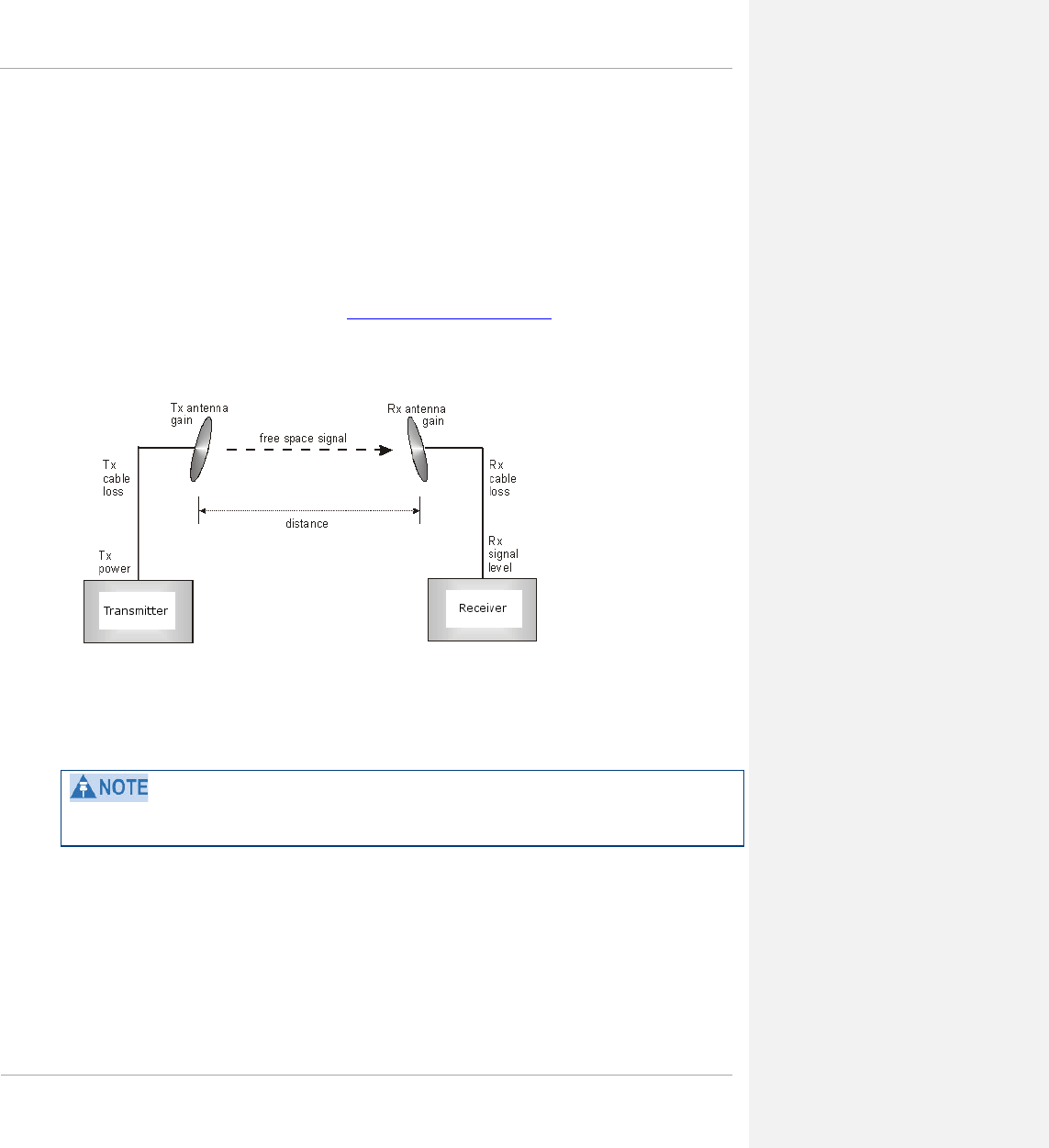
PMP 450 Planning Guide
Calculating Link Loss
The link loss is the total attenuation of the wireless signal between two point-to-multipoint units. The link loss
calculation is presented below:
Link Loss (dB) = Transmit power of the remote wireless unit (dBm) − Tx Cable loss (dB) − Received
power at the local unit (dBm) – Rx cable loss (dB) + Antenna gain at the remote unit (dBi) + Antenna gain at
the local unit (dBi)
Calculating Rx Signal Level
The Rx sensitivity of each module is provided at http://www.cambiumnetworks.com. The determinants in Rx signal
level are illustrated in Figure 17.
Figure 17 Determinants in Rx signal level
Rx signal level is calculated as follows:
Rx signal level dB = Tx power − Tx cable loss + Tx antenna gain
− free space path loss + Rx antenna gain − Rx cable loss
This Rx signal level calculation presumes that a clear line of sight is established between the transmitter and
receiver and that no objects encroach in the Fresnel zone.
pmp-0047 (March 2014) 1-93

PMP 450 Planning Guide
Calculating Fade Margin
Free space path loss is a major determinant in Rx (received) signal level. Rx signal level, in turn, is a major factor in
the system operating margin (fade margin), which is calculated as follows:
system operating margin (fade margin) dB =Rx signal level dB − Rx sensitivity dB
Thus, fade margin is the difference between strength of the received signal and the strength that the receiver
requires for maintaining a reliable link. A higher fade margin is characteristic of a more reliable link.
Analyzing the RF Environment
An essential element in RF network planning is the analysis of spectrum usage and the strength of the signals that
occupy the spectrum you are planning to use. Regardless of how you measure and log or chart the results you find
(through the Spectrum Analyzer in SM feature or by using a spectrum analyzer), you should do so:
• at various times of day.
• on various days of the week.
• periodically into the future.
As new RF neighbors move in or consumer devices in your spectrum proliferate, this will keep you aware of the
dynamic possibilities for interference with your network.
Mapping RF Neighbor Frequencies
These modules allow you to
• use an SM or an AP that is temporarily transformed into an SM, as a spectrum analyzer.
• view a graphical display that shows power level in RSSI and dBm at 5-MHz increments throughout the
frequency band range, regardless of limited selections in the Custom Radio Frequency Scan Selection List
parameter of the SM.
• select an AP channel that minimizes interference from other RF equipment.
The following procedure causes the SM to drop any active RF link. If a link is dropped when the spectrum analysis begins, the
link can be re-established when either a 15-minute interval has elapsed or the spectrum analyzer feature is disabled.
1-94 pmp-0047 (March 2014)
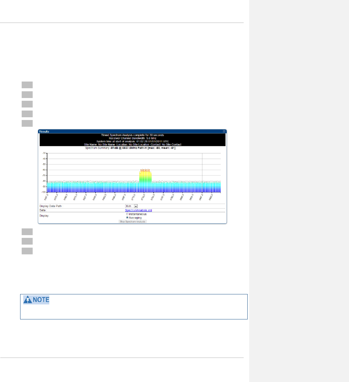
PMP 450 Planning Guide
Analyzing the spectrum
To use the built-in spectrum analyzer functionality of the SM (or AP that is temporarily configured as an SM for
spectrum analysis via the AP’s GUI) proceed as follows:
Procedure 3 Analyzing the spectrum
1 Predetermine a power source and interface that will work for the SM in the area you want to analyze.
2 Take the SM, power source, and interface device to the area.
3 Access the Tools web page of the SM.
4 Click Start Timed Spectrum Analysis
5 After 10 seconds, the results are displayed:
6 Travel to another location in the area.
7 Click Start Timed Spectrum Analysis
8 Repeat Steps 6 and 7 until the area has been adequately scanned and logged.
As with any other data that pertains to your business, a decision today to put the data into a retrievable database
may grow in value to you over time. The Spectrum Analyzer contains configurable parameters to fit your business
requirements. See the PMP 450 Operations Guide for further information.
Wherever you find the measured noise level is greater than the sensitivity of the radio that you plan to deploy, use
the noise level (rather than the link budget) for your link feasibility calculations.
pmp-0047 (March 2014) 1-95

PMP 450 Planning Guide
Anticipating Reflection of Radio Waves
In the signal path, any object that is larger than the wavelength of the signal can reflect the signal. Such an object
can even be the surface of the earth or of a river, bay, or lake. The wavelength of the signal is approximately
• 2 inches for 2.4, 3.5GHz, 3.6 GHz, 5.4-GHz and 5.8-GHz signals.
A reflected signal can arrive at the antenna of the receiver later than the non-reflected signal arrives. These two or
more signals cause the condition known as multipath. Multipath may increase or decrease the signal level and so
overall attenuation may be higher or lower than that caused by the link distance. This is problematic at the margin
of the link budget, where the standard operating margin (fade margin) may be compromised.
Noting Possible Obstructions in the Fresnel Zone
The Fresnel (pronounced fre∙NEL) Zone is a three-dimensional volume around the line of sight of an antenna
transmission. Objects that penetrate this area can cause the received strength of the transmitted signal to fade. Out-
of-phase reflections and absorption of the signal result in signal cancellation.
The foliage of trees and plants in the Fresnel Zone can cause signal loss. Seasonal density, moisture content of the
foliage, and other factors such as wind may change the amount of loss. Plan to perform frequent and regular link
tests if you must transmit though foliage.
1-96 pmp-0047 (March 2014)
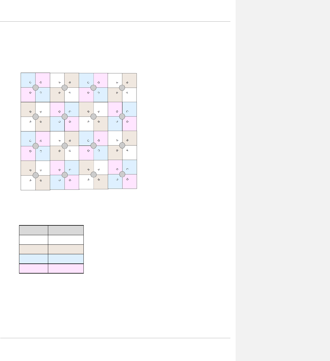
PMP 450 Planning Guide
Multiple OFDM Access Point Clusters
When deploying multiple AP clusters in a dense area, consider aligning the clusters as shown below. However, this
is only a recommendation. An installation may dictate a different pattern of channel assignments.
Figure 18 Example layout of 16 Access Point sectors (ABCD), 90 degree sectors
An example for assignment of frequency channels is provided in the following table.
See section Network migration planning on page 1-56 for more information on migrating to a PMP 450 network.
Table 50 Example 5.8-GHz OFDM channel assignment by sector
Symbol Frequency
A 5.740 GHz
B 5.760 GHz
C 5.780 GHz
D 5.800 GHz
pmp-0047 (March 2014) 1-97
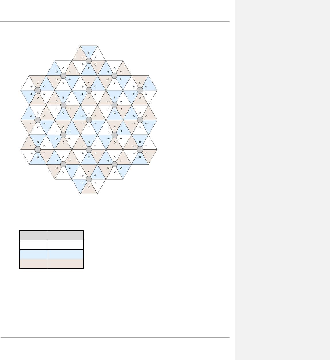
PMP 450 Planning Guide
Figure 19 Example layout of 16 Access Point sectors (ABC), 60 degree sectors
An example for assignment of frequency channels and sector IDs is provided in the following table.
See section Network migration planning on page 1-56 for more information on migrating to a PMP 450 network.
Table 51 Example 5.8-GHz OFDM channel assignment by sector
Symbol Frequency
A 5.740 GHz
B 5.760 GHz
C 5.780 GHz
1-98 pmp-0047 (March 2014)
PMP 450 Planning Guide
Planning for co-location and using the OFDM Frame Calculator Tool
The first step to avoid interference in wireless systems is to set all APs to receive timing from a synchronization
source (Cluster Management Module, or Universal Global Positioning System). This ensures that the modules are
in sync and start transmitting at the same time each frame.
The second step to avoid interference is to configure parameters on all APs of the same frequency band in
proximity such that they have compatible transmit/receive ratios (all stop transmitting each frame before any start
receiving). This avoids the problem of one AP attempting to receive the signal from a distant SM while a nearby AP
transmits, which could overpower that signal.
The following parameters on the AP determine the transmit/receive ratio:
• Max Range
• Downlink Data percentage
• (reserved) Control Slots
If OFDM (PMP 430, PMP 450, PTP 230) and FSK (PMP 1x0) APs of the same frequency band are in proximity, or
if you want APs set to different parameters (differing in their Max Range values, for example), then you should use
the Frame Calculator to identify compatible settings.
The frame calculator is available on the Frame Calculator tab of the Tools web page. To use the Frame Calculator,
type into the calculator various configurable parameter values for each proximal AP, and then record the resulting
AP Receive Start value. Next vary the Downlink Data percentage in each calculation and iterate until the
calculated AP Receive Start for all collocated APs are within 300 bit times; if possible, within 150 bit times. In
Cambium Point-to-Multipoint systems, 10 bit times = 1 µs.
The calculator does not use values in the module or populate its parameters. It is merely a convenience application
that runs on a module. For this reason, you can use any FSK module (AP, SM, BHM, BHS) to perform FSK frame
calculations for setting the parameters on an FSK AP and any OFDM module (AP, SM, BHM, BHS) to perform
OFDM frame calculations for setting the parameters on an OFDM AP.
IMPORTANT!
APs that have slightly mismatched transmit-to-receive ratios and low levels of data traffic may
see little effect on throughput. A system that was not tuned for co-location may work fine at
low traffic levels, but encounter problems at higher traffic levels. The conservative practice is
to tune for co-location
before traffic ultimately increases. This prevents problems that occur as
sectors are built.
pmp-0047 (March 2014) 1-99
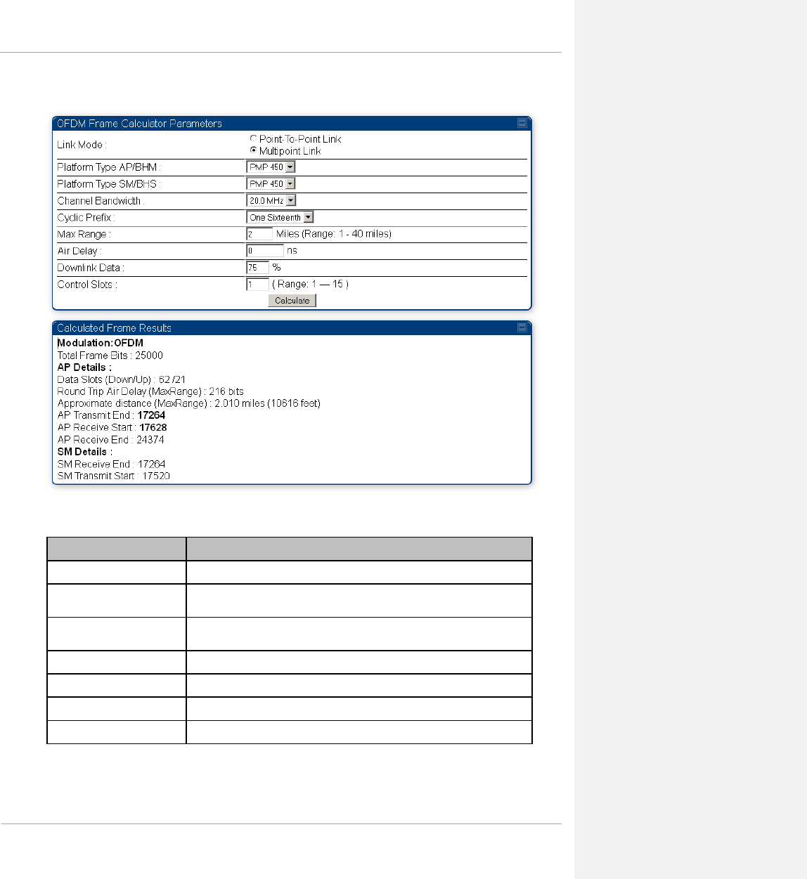
PMP 450 Planning Guide
Figure 20 OFDM Frame Calculator tab
In the Frame Calculator tab, you can set the following parameters.
Table 52 OFDM Frame Calculator tab attributes
Attribute Meaning
Link Mode For AP to SM frame calculations, select Multipoint Link
Platform Type AP/BHM Use the drop-down list to select the hardware series (board type) of the
AP.
Platform Type SM/BHS Use the drop-down list to select the hardware series (board type) of the
SM.
Channel Bandwidth Set this to the channel bandwidth used in the AP.
Cyclic Prefix Set this to the cyclic prefix used in the AP.
Max Range Set to the same value as the Max Range parameter is set in the AP(s).
Air Delay This field should be left at the default of 0 ns.
1-100 pmp-0047 (March 2014)

PMP 450 Planning Guide
Attribute Meaning
Downlink Data Initially set this parameter to the same value that the AP has for its
Downlink Data parameter (percentage). Then, as you use the Frame
Calculator tool in Procedure 4, you will vary the value in this parameter to
find the proper value to write into the Downlink Data parameter of all
APs in the cluster.
PMP 450 Series APs offer a range of 15% to 85%, and default to 75%.
The value that you set in this parameter has the following interaction with
the value of the Max Range parameter (above):
The default Max Range value is 5 miles and, at that distance, the
maximum Downlink Data value (85% in PMP450) is functional.
Control Slots Set this parameter to the value of the Control Slot parameter is set in the
APs.
The Calculated Frame Results display several items of interest:
Table 53 OFDM Calculated Frame Results attributes
Attribute Meaning
Modulation The type of radio modulation used in the calculation (OFDM for PMP
450)
Total Frame Bits The total number of bits used in the calculated frames
Data Slots (Down/Up) This field is based on the Downlink Data setting. For example, a result
within the typical range for a Downlink Data setting of 75% is 61/21,
meaning 61 data slots down and 21 data slots up.
Round Trip Air Delay
(MaxRange)
This is the roundtrip air delay in bit times for the Max Range value set in
the calculator
Approximate distance
(MaxRange)
The Max Range value used for frame calculation
AP Transmit End In bit times, this is the frame position at which the AP ceases transmission.
AP Receive Start In bit times, this is the frame position at which the AP is ready to receive
transmission from the SM.
AP Receive End In bit times, this is the frame position at which the AP will cease receiving
transmission from the SM.
SM Receive End In bit times, this is the frame position at which the SM will cease receiving
transmission from the AP.
SM Transmit Start In bit times, this is the frame position at which the SM will begin
transmission.
pmp-0047 (March 2014) 1-101

PMP 450 Planning Guide
To use the Frame Calculator to ensure that all APs are configured to transmit and receive at the same time, follow
the procedure below:
Procedure 4 Using the Frame Calculator
1 Populate the OFDM Frame Calculator parameters with appropriate values as described
above.
2 Click the Calculate button.
3 Scroll down the tab to the Calculated Frame Results section
4 Record the value of the AP Receive Start field
5 Enter a parameter set from another AP in the system – for example, an AP in the same
cluster that has a higher Max Range value configured.
6 Click the Calculate button.
7 Scroll down the tab to the Calculated Frame Results section
8 If the recorded values of the AP Receive Start fields are within 150 bit times of each
other, skip to step 10.
9 If the recorded values of the AP Receive Start fields are not within 150 bit times of each
other, modify the Downlink Data parameter until the calculated results for AP Receive
Start are within 300 bit time of each other, if possible, 150 bit time.
10 Access the Radio tab in the Configuration web page of each AP in the cluster and change
its Downlink Data parameter (percentage) to the last value that was used in the Frame
Calculator.
Selecting Sites for Network Elements
The APs must be positioned
• with hardware that the wind and ambient vibrations cannot flex or move.
• where a tower or rooftop is available or can be erected.
• where a grounding system is available.
• with lightning arrestors to transport lightning strikes away from equipment.
• at a proper height:
o higher than the tallest points of objects immediately around them (such as trees, buildings, and tower legs).
o at least 2 feet (0.6 meters) below the tallest point on the tower, pole, or roof (for lightning protection).
• away from high-RF energy sites (such as AM or FM stations, high-powered antennas, and live AM radio
towers).
• in line-of-sight paths
o to the SMs.
o that will not be obstructed by trees as they grow or structures that are later built.
1-102 pmp-0047 (March 2014)

PMP 450 Planning Guide
Visual line of sight does not guarantee radio line of sight.
Surveying Sites
Factors to survey at potential sites include
• what pre-existing wireless equipment exists at the site. (Perform spectrum analysis.)
• whether available mounting positions exist near the lowest elevation that satisfies line of site, coverage, and
other link criteria.
• whether you will always have the right to decide who climbs the tower to install and maintain your equipment,
and whether that person or company can climb at any hour of any day.
• whether you will have collaborative rights and veto power to prevent interference to your equipment from
wireless equipment that is installed at the site in the future.
• whether a pre-existing grounding system (path to Protective Earth ) exists, and what is required to establish a
path to it.
• who is permitted to run any indoor lengths of cable.
Clearing the Radio Horizon
Because the surface of the earth is curved, higher module elevations are required for greater link distances. This
effect can be critical to link connectivity in link spans that are greater than 8 miles (12 km).
To use metric units to find the minimum height required to reach the radio horizon use the following equation:
Radio horizon distance (km) = 4.12 (SQRT(h1) + SQRT(h2))
Where: Is:
h1 height of the AP
h2 height of the SM
To use English standard units to find the angle of elevation, use the following formula:
Radio horizon distance (km) = 1.42 (SQRT(h1) + SQRT(h2))
Where: Is:
h1 height of the AP
h2 height of the SM
pmp-0047 (March 2014) 1-103

PMP 450 Planning Guide
Calculating the Aim Angles
The proper angle of tilt can be calculated as a factor of both the difference in elevation and the distance that the link
spans. Even in this case, a plumb line and a protractor can be helpful to ensure the proper tilt. This tilt is typically
minimal.
The number of degrees to offset (from vertical) the mounting hardware leg of the support tube is equal to the angle
of elevation from the lower module to the higher module (<B in the example provided in Figure 21).
Figure 21 Variables for calculating angle of elevation (and depression)
Where: Is:
b angle of elevation
B vertical difference in elevation
A horizontal distance between modules
Calculating the Angle of Elevation
To use metric units to find the angle of elevation, use the following formula:
Where: Is:
B expressed in meters
A expressed in kilometers
To use English standard units to find the angle of elevation, use the following formula:
Where: Is:
B expressed in feet
A expressed in miles
The angle of depression from the higher module is identical to the angle of elevation from the lower module.
tan b = B
1000A
tan b = B
5280A
1-104 pmp-0047 (March 2014)

PMP 450 Planning Guide
Diagramming Network Layouts
Avoiding Self Interference
The following section includes information maximizing tower performance by minimizing self-interference.
Physical Proximity
Two AP clusters co-located on the same tower require a CMM. The CMM properly synchronizes the transmit start
times of all modules to prevent interference and de-sensing of the modules. At closer distances without GPS
synchronization, the frame structures cause self-interference. Non-synchronized deployments are highly
discouraged.
Furthermore, non-synchronized APs on the same tower require that the effects of their differing receive start times
be mitigated by either
• 100 vertical feet (30 meters) or more and as much spectral separation as possible within the same frequency
band range
• the use of the frame calculator to tune the Downlink Data parameter in each, so that the receive start time in
each is the same
The constraints for collocated modules in the same frequency band range are to avoid self-interference that would
occur between them. Specifically, unless the uplink and downlink data percentages match, intervals exist when one
is transmitting while the other is receiving, such that the receiving module cannot receive the signal from the far
end.
The interference is less a problem during low throughput periods and intolerable during high. Typically, during low
throughput periods, sufficient time exists for the far end to retransmit packets lost because of interference from the
collocated module.
Spectrum Analysis
You can use an SM as a spectrum analyzer. See Mapping RF Neighbor Frequencies on Page 1-94. Through a toggle
of the Device Type parameter, you can temporarily transform an AP into an SM to use it as a spectrum analyzer.
SM Automatic Transmit Power Control
The PMP 450 AP automatically sets the transmitter output power in its SMs through a feature named Auto-TPC
(Transmit Power Control). The conceptual reason for this feature is OFDM reception in the AP is sensitive to large
differences in power levels received from its SMs, and by limiting power levels of close-in SMs the overall RF
noise floor is lowered.
pmp-0047 (March 2014) 1-105
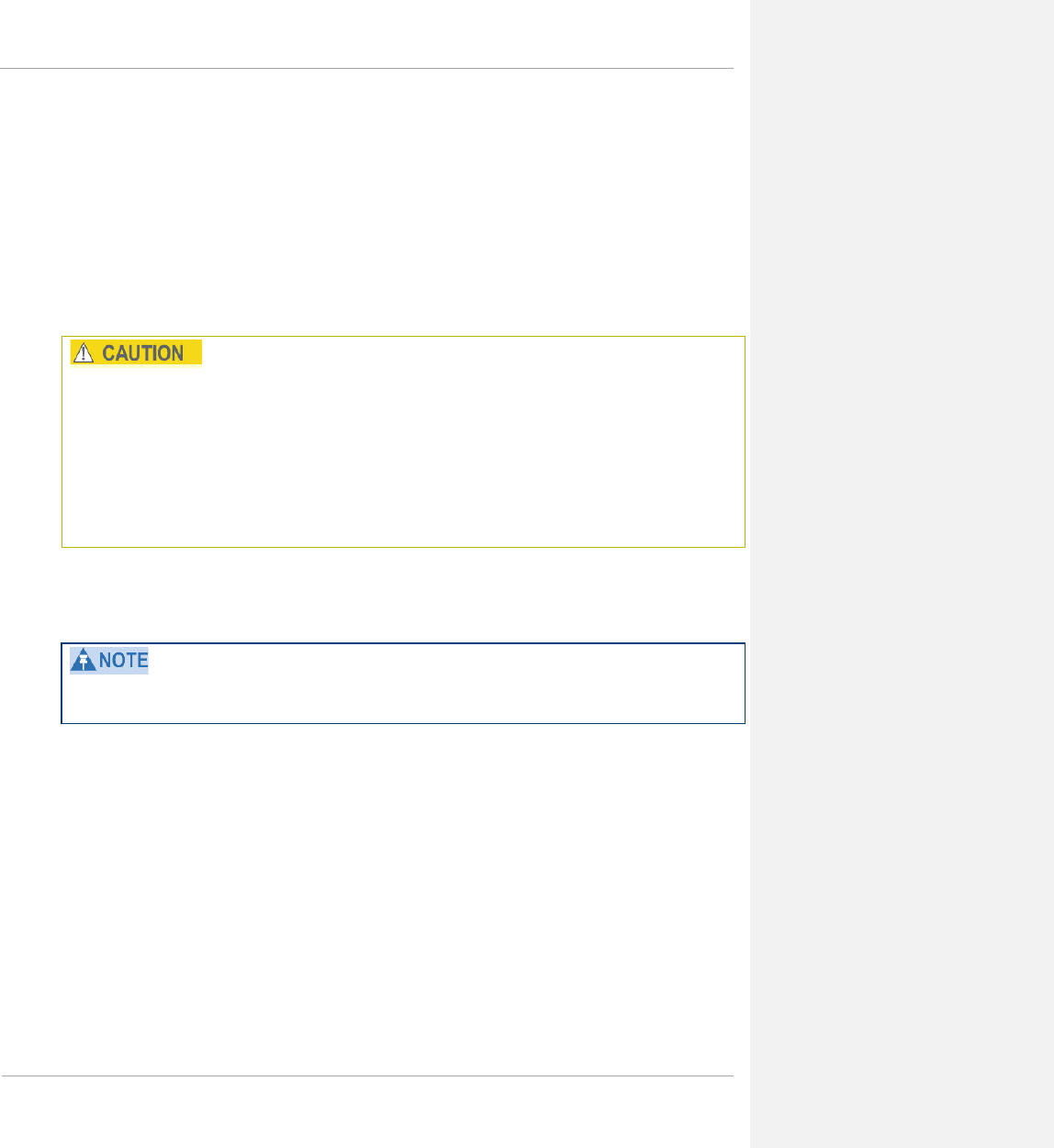
PMP 450 Planning Guide
Avoiding Other Interference
Where signal strength cannot dominate noise levels, the network experiences
• packet errors and retransmissions.
• lower throughput (because bandwidth is consumed by retransmissions) and high latency (due to resends).
Regular spectrum analysis is critical to RF planning. The integrated spectrum analyzer can be very useful as a tool
for troubleshooting and RF planning, but is not intended to replicate the accuracy and programmability of a high-
end spectrum analyzer, which you may sometime need for other purposes.
When you enable the Spectrum Analyzer on a module, it enters a scan mode and drops any RF connection it may
have had. Scanning mode ends when either you click Disable on the Spectrum Analyzer page, or it times out after
15 minutes and returns to operational mode.
For this reason:
1. do not enable the spectrum analyzer on a module you are connected to via RF. The connection will drop for
15 minutes, and when the connection is re-established no readings will be displayed.
2. be advised that, if you enable the spectrum analyzer by Ethernet connection, the RF connection to that module
drops.
You can use any module to see the frequency and power level of any detectable signal that is within, just above, or
just below the frequency band range of the module.
Vary the days and times when you analyze the spectrum in an area.
The RF environment can change throughout the day or throughout the week.
1-106 pmp-0047 (March 2014)

PMP 450 Planning Guide
Grounding and lightning protection
This section describes the grounding and lightning protection requirements of a PMP 450 installation.
Electro-magnetic discharge (lightning) damage is not covered under warranty. The recommendations in
this guide, when followed correctly, give the user the best protection from the harmful effects of EMD.
However 100% protection is neither implied nor possible.
The need for power surge protection
Structures, equipment and people must be protected against power surges (typically caused by lightning) by
conducting the surge current to ground via a separate preferential solid path. The actual degree of protection
required depends on local conditions and applicable local regulations. Cambium recommends that PMP 450
installation is contracted to a professional installer.
Standards
Full details of lightning protection methods and requirements can be found in the international standards IEC
61024-1 and IEC 61312-1, the U.S. National Electric Code ANSI/NFPA No. 70-1984 or section 54 of the Canadian
Electric Code.
pmp-0047 (March 2014) 1-107

PMP 450 Planning Guide
Lightning protection zones
The ‘rolling sphere method’ (Figure 22) is used to determine where it is safe to mount equipment. An imaginary
sphere, typically 50 meters in radius, is rolled over the structure. Where the sphere rests against the ground and a
strike termination device (such as a finial or ground bar), all the space under the sphere is considered to be in the
zone of protection (Zone B). Similarly, where the sphere rests on two finials, the space under the sphere is
considered to be in the zone of protection.
Figure 22 Rolling sphere method to determine the lightning protection zones
Error! No topic specified.
Assess locations on masts, towers and buildings to determine if the location is in Zone A or Zone B:
• Zone A: In this zone a direct lightning strike is possible. Do not mount equipment in this zone.
• Zone B: In this zone, direct EMD (lightning) effects are still possible, but mounting in this zone significantly
reduces the possibility of a direct strike. Mount equipment in this zone.
Never mount equipment in Zone A. Mounting in Zone A may put equipment, structures and life at risk.
1-108 pmp-0047 (March 2014)

PMP 450 Planning Guide
General protection requirements
To adequately protect a PMP 450 installation, both ground bonding and transient voltage surge suppression are
required.
Basic requirements
The following basic protection requirements must be implemented:
• The equipment must be in ‘Zone B’ (see Lightning protection zones on page 1-108).
• The AP must be grounded to the supporting structure.
• A surge suppression unit (600SS) must be installed close to the SM.
• The distance between the SM and 600SS should be kept to a minimum.
• The drop cable length between the SM and 600SS must be less than 600 mm.
• An surge suppression unit (200SS) must be installed within 600 mm (24 in) of the point at which the power
cable enters the building or equipment room.
• The drop cable must be grounded at the building entry point.
• The drop cable must not be laid alongside a lightning air terminal.
• All grounding cables must be a minimum size of 10 mm2 csa (8AWG), preferably 16 mm2 csa (6AWG), or 25
mm2 csa (4AWG).
Grounding cable requirements
When routing, fastening and connecting grounding cables, the following requirements must be implemented:
• Grounding conductors must be run as short, straight, and smoothly as possible, with the fewest possible number
of bends and curves.
• Grounding cables must not be installed with drip loops.
• All bends must have a minimum radius of 203 mm (8 in) and a minimum angle of 90° (Figure 23). A diagonal
run is preferable to a bend, even though it does not follow the contour or run parallel to the supporting
structure.
• All bends, curves and connections must be routed towards the grounding electrode system, ground rod, or
ground bar.
• Grounding conductors must be securely fastened.
• Braided grounding conductors must not be used.
• Approved bonding techniques must be used for the connection of dissimilar metals.
Figure 23 Grounding cable minimum bend radius and angle
Error! No topic specified.
pmp-0047 (March 2014) 1-109

PMP 450 Planning Guide
Protection requirements for a mast or tower installation
If the AP or SM is to be mounted on a metal tower or mast, then in addition to the general protection requirements
(above), the following requirements must be observed:
• The equipment must be lower than the top of the tower or its lightning air terminal.
• The metal tower or mast must be correctly grounded.
• A grounding kit must be installed at the first point of contact between the drop cable and the tower, near the
top.
• A grounding kit must be installed at the bottom of the tower, near the vertical to horizontal transition point.
This grounding kit must be bonded to the tower or tower ground bus bar (TGB), if installed.
Schematic examples of mast or tower installations are shown in Figure 24.
Figure 24 Grounding and lightning protection on mast or tower
Error! No topic specified.
1-110 pmp-0047 (March 2014)

PMP 450 Planning Guide
Protection requirements for a wall installation
If the SM is to be mounted on the wall of a building, then in addition to the general protection requirements
(above), the following requirements must be observed:
• The equipment must be lower than the top of the building or its lightning air terminal.
• The building must be correctly grounded.
Schematic examples of wall installations are shown in Figure 25.
Figure 25 Grounding and lightning protection on wall
Error! No topic specified.
pmp-0047 (March 2014) 1-111


PMP 450 Planning Guide
Figure 26) and the equipment room is several floors below (Figure 27). The following additional requirements must
be observed:
• The AP must be below the lightning terminals and finials.
• A grounding conductor must be installed around the roof perimeter, to form the main roof perimeter lightning
protection ring.
• Air terminals are typically installed along the length of the main roof perimeter lightning protection ring
typically every 6.1m (20ft).
• The main roof perimeter lightning protection ring must contain at least two down conductors connected to the
grounding electrode system. The down conductors should be physically separated from one another, as far as
practical.
pmp-0047 (March 2014) 1-113

PMP 450 Planning Guide
Figure 26 Grounding and lightning protection on building
Error! No topic specified.
Protection inside a high rise building
The following protection requirements must be observed inside multi-story or high rise buildings (Figure 27):
• The drop cable shield must be bonded to the building grounding system at the entry point to the building.
• The drop cable shield must be bonded to the building grounding system at the entry point to the equipment
area.
Figure 27 Grounding and lightning protection inside high building
Error! No topic specified.
1-114 pmp-0047 (March 2014)

PMP 450 Planning Guide
Configuration options for TDD synchronization
The PMP 450 system uses Time Division Duplexing (TDD) - one channel alternately transmits and receives - rather
than using one channel for transmitting and a second channel for receiving. To accomplish TDD, the AP must
provide sync to its SMs – it must keep them in sync. Furthermore, collocated APs must be synced together - an
unsynchronized AP that transmits during the receive cycle of a collocated AP can prevent that second AP from
being able to decode the signals from its SMs. In addition, across a geographical area, APs that can “hear” each
other benefit from using a common sync to further reduce self-interference within the network.
The configuration options available for synchronization on the PMP 450 Access Point are:
• AutoSync: The AP automatically receives sync from one of the following sources:
o GPS Sync over Timing Port (UGPS, co-located AP GPS sync output, or “Remote AP” feed from a
registered SM’s GPS sync output)
o GPS Sync over Power Port (CMM)
o On-board GPS (internal GPS)
Upon AP power on, the AP does not transmit until a valid synchronization pulse is received from one of the
sources above. When there are synchronization sources on both the timing port and the power port, the power
port GPS source will be chosen first.
If there is a loss of GPS synchronization pulse, within two seconds the AP automatically attempts to source
GPS signaling from another source. On-board GPS (internal GPS) is the last source checked for GPS signaling
if there is no receipt of signaling from the timing port or from the power port. AutoSync will source timing
from the on-board GPS if a valid synchronization pulse is detected (the on-board GPS module should not be
used as the primary timing source). If no valid GPS signal is received, the AP ceases transmission and SM
registration is lost until a valid GPS signal is received again on the AP.
• AutoSync + Free Run: This mode operates similarly to mode “AutoSync”, but if a previously received
synchronization signal is lost and no GPS signaling alternative is achieved (from the timing port, power port, or
on-board GPS), the AP automatically changes to synchronization mode “Generate Sync”. While SM
registration ins maintained, in this mode there is no synchronization of APs that can “hear” each other; the AP
will only generate a sync signal for the local AP and its associated SMs. Once a valid GPS signal is obtained
again, the AP automatically switches to receiving synchronization via the GPS source and SM registration is
maintained.
In mode AutoSync + Free Run, if a GPS signal is never achieved initially, the system will not switch to “Free
Run” mode, and SMs will not register to the AP. A valid GPS signal must be present initially for the AP to switch
into “Free Run” mode (and to begin self-generating a synchronization pulse).
• Generate Sync (factory default): This option may be used when the AP is not receiving GPS synchronization
pulses from either a CMM or UGPS module, and there are no other APs active within the link range. Using this
option will not synchronize transmission of APs that can “hear” each other; it will only generate a sync signal
for the local AP and its associated SMs. See Advantage of GPS synchronization on page 1-117.
pmp-0047 (March 2014) 1-115

PMP 450 Planning Guide
GPS synchronization
The Navigation Satellite Timing and Ranging (NAVSTAR) Global Positioning System (GPS) use 24 satellites to
relay information for precise derivation of position and time.
The cluster management module (CMM) contains a Cambium GPS Receiver. The CMM is a critical element in the
operation of the system. At one AP cluster site or throughout an entire wireless system, the CMM provides a GPS
timing pulse to each module, synchronizing the network transmission cycles.
The Oncore GPS Receiver tracks eight or more NAVSTAR satellites. The CMM uses the signal from at least four
of these satellites to generate a one-second interval clock that has a rise time of 100 nsec. This clock directly
synchronizes APs and which, in turn, synchronize the SMs in the network.
The Oncore GPS Receiver also provides
• the latitude and longitude of the GPS antenna (collocated with the CMM)
• the number of satellites that are being tracked
• the number of satellites that are available
• the date
• the time in Universal Coordinated Time (UCT)
• the altitude of the GPS antenna
• other information that can be used to diagnose network problems.
Alternative to GPS synchronization
A link can operate without GPS sync, but cannot operate without sync. The alternative to GPS sync is to configure
the AP in the link to generate a sync pulse to pass to the SM. Depending on the RF environment in which the link
operates, this latter alternative may or may not be plausible.
For example, in Figure 28, AP4
• is not synchronized with any of the other APs.
• is transmitting nearby the other APs while they are expecting to receive SM transmissions from a maximum
distance.
1-116 pmp-0047 (March 2014)
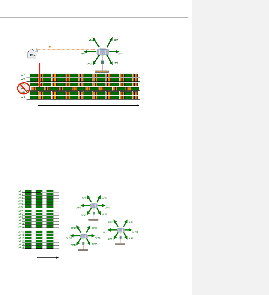
PMP 450 Planning Guide
Figure 28 One unsynchronized AP in cluster resulting in self-interference
The result is self-interference. In this scenario, the self-interference can be avoided only by synchronizing the TDD
transmit cycles of all APs that operate in the same frequency band.
An AP that is isolated by at least 5 miles (8 km) from any other equipment can generate and pass sync pulse without
GPS timing and not risk that interference will result from the generated sync. In any other type of link, sync should
be derived from GPS timing.
Advantage of GPS synchronization
Although the embedded timing generation capability of the AP keeps a precise clock (configuration parameter Sync
Input set to Generate Sync Signal), no trigger exists to start the clock at the same moment in each AP of a cluster.
So, the individual AP can synchronize communications between itself and registered SMs, but cannot synchronize
itself with other modules, except by GPS timing (shown in Figure 29).
Figure 29 GPS timing throughout the network
Time
Time
pmp-0047 (March 2014) 1-117

PMP 450 Planning Guide
Mounting the GPS receiver (CMM or UGPS) module on the
equipment building
If mounting the GPS receiver on the equipment building, select a position on the wall that meets the following
requirements:
• It must be below the roof height of the equipment building or below the height of any roof-mounted equipment
(such as air conditioning plant).
• It must be below the lightning air terminals.
• It must not project more than 600mm (24 inches) from the wall of the building.
If these requirements cannot all be met, then the module must be mounted on a metal tower or mast.
Mounting the GPS receiver (CMM or UGPS) module on a metal tower
or mast
If mounting the GPS receiver module on a metal tower or mast, select a position that meets the following
requirements:
• It must not be mounted any higher than is necessary to receive an adequate signal from four GPS satellites.
• It must be protected by a nearby lightning air terminal that projects farther out from the tower than the GPS
receiver module.
• It must meet all the requirements stated in Protection requirements for a mast or tower installation on page 1-
110.
1-118 pmp-0047 (March 2014)
PMP 450 Planning Guide
Data network planning
This section describes factors to be considered when planning PMP 450 data networks.
Understanding addresses
A basic understanding of Internet Protocol (IP) address and subnet mask concepts is required for engineering your
IP network.
IP address
The IP address is a 32-bit binary number that has four parts (octets). This set of four octets has two segments,
depending on the class of IP address. The first segment identifies the network. The second identifies the hosts or
devices on the network. The subnet mask marks a boundary between these two sub-addresses.
Dynamic or static addressing
For any computer to communicate with a module, the computer must be configured to either
• use DHCP (Dynamic Host Configuration Protocol). In this case, when not connected to the network, the
computer derives an IP address on the 169.254 network within two minutes.
• have an assigned static IP address (for example, 169.254.1.5) on the 169.254 network.
If an IP address that is set in the module is not the 169.254.x.x network address, then the network operator must
assign the computer a static IP address in the same subnet.
When a DHCP server is not found
To operate on a network, a computer requires an IP address, a subnet mask, and possibly a gateway address. Either
a DHCP server automatically assigns this configuration information to a computer on a network or an operator must
input these items.
When a computer is brought on line and a DHCP server is not accessible (such as when the server is down or the
computer is not plugged into the network), Microsoft and Apple operating systems default to an IP address of
169.254.x.x and a subnet mask of 255.255.0.0 (169.254/16, where /16 indicates that the first 16 bits of the address
range are identical among all members of the subnet).
pmp-0047 (March 2014) 1-119
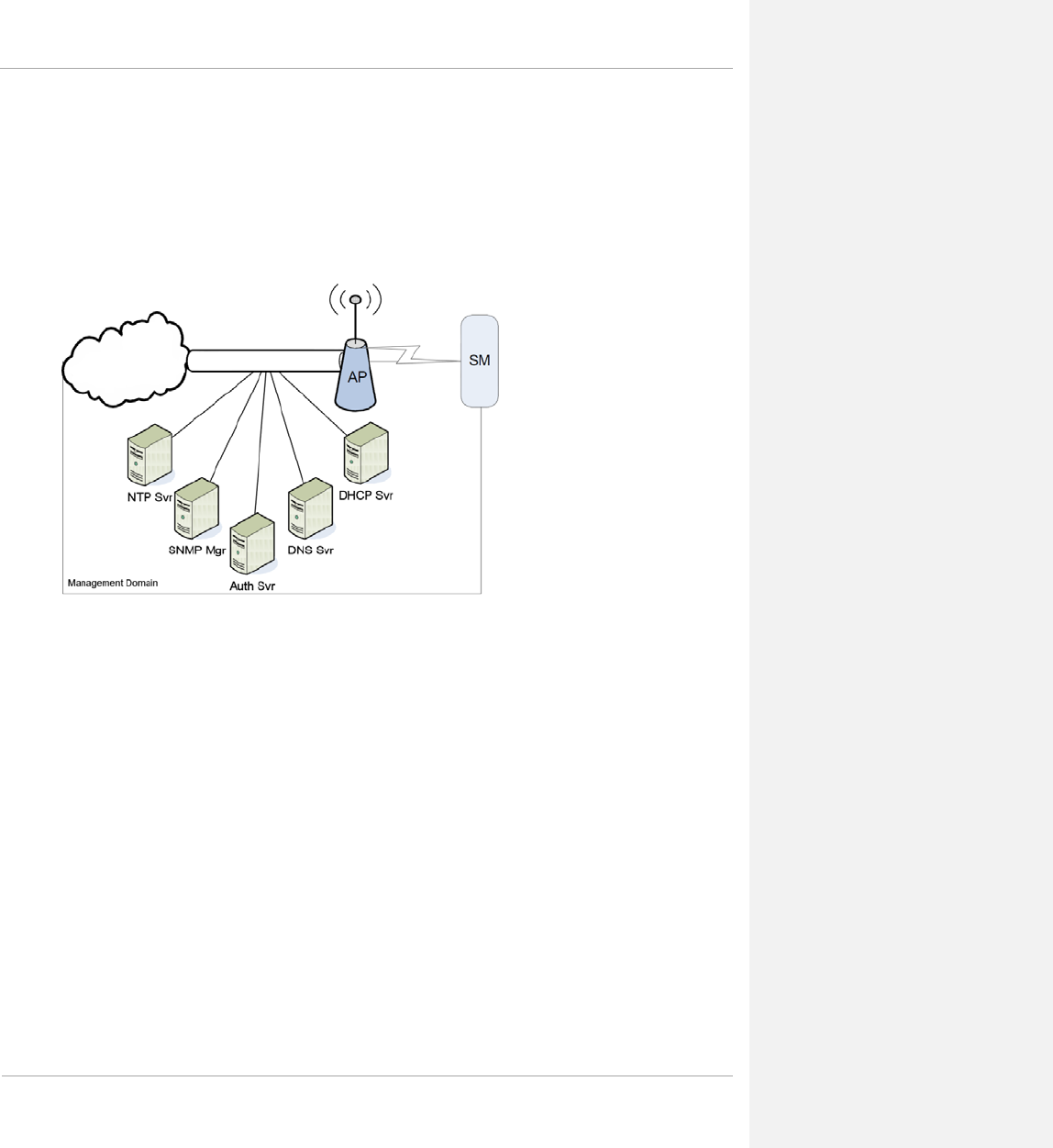
PMP 450 Planning Guide
DNS Client
The DNS Client is used to resolve names of management servers within the operator’s management domain (see
Figure 30). This feature allows hostname configuration for NTP servers, Authorization Servers, DHCP relay
servers, and SNMP trap servers. Operators may choose to either enter in the FQDN (Fully Qualified Domain Name)
for the host name or to manually enter the IP addresses of the servers.
Figure 30 Cambium network management domain
Network Address Translation (NAT)
NAT, DHCP Server, DHCP Client, and DMZ in SM
The system provides NAT (network address translation) for SMs in the following combinations of NAT and DHCP
(Dynamic Host Configuration Protocol):
• NAT Disabled
• NAT with DHCP Client (DHCP selected as the Connection Type of the WAN interface) and DHCP Server
• NAT with DHCP Client(DHCP selected as the Connection Type of the WAN interface)
• NAT with DHCP Server
• NAT without DHCP
NAT
NAT isolates devices connected to the Ethernet/wired side of an SM from being seen directly from the wireless side
of the SM. With NAT enabled, the SM has an IP address for transport traffic (separate from its address for
management), terminates transport traffic, and allows you to assign a range of IP addresses to devices that are
connected to the Ethernet/wired side of the SM.
1-120 pmp-0047 (March 2014)
PMP 450 Planning Guide
In the Cambium system, NAT supports many protocols, including HTTP, ICMP (Internet Control Message
Protocols), and FTP (File Transfer Protocol). For virtual private network (VPN) implementation, L2TP over IPSec
(Level 2 Tunneling Protocol over IP Security) and PPTP (Point to Point Tunneling Protocol) are supported.
When NAT is enabled, a reduction in throughput is introduced at the SM (due to processing overhead).
DHCP
DHCP enables a device to be assigned a new IP address and TCP/IP parameters, including a default gateway,
whenever the device reboots. Thus DHCP reduces configuration time, conserves IP addresses, and allows modules
to be moved to a different network within the Cambium system.
In conjunction with the NAT features, each SM provides
• a DHCP server that assigns IP addresses to computers connected to the SM by Ethernet protocol.
• a DHCP client that receives an IP address for the SM from a network DHCP server.
DMZ
In conjunction with the NAT features, a DMZ (demilitarized zone) allows the assignment of one IP address behind
the SM for a device to logically exist outside the firewall and receive network traffic. The first three octets of this IP
address must be identical to the first three octets of the NAT private IP address.
Developing an IP addressing scheme
Network elements are accessed through IP Version 4 (IPv4) addressing.
A proper IP addressing method is critical to the operation and security of a network.
Each module requires an IP address on the network. This IP address is for only management purposes. For security,
you should either
• assign a non-routable IP address.
• assign a routable IP address only if a firewall is present to protect the module.
You will assign IP addresses to computers and network components by either static or dynamic IP addressing. You
will also assign the appropriate subnet mask and network gateway to each module.
Address Resolution Protocol
As previously stated, the MAC address identifies a module in
• communication between modules.
• the data that modules store about each other.
The IP address is essential for data delivery through a router interface. Address Resolution Protocol (ARP)
correlates MAC addresses to IP addresses.
pmp-0047 (March 2014) 1-121

PMP 450 Planning Guide
For communications to outside the network segment, ARP reads the network gateway address of the router and
translates it into the MAC address of the router. Then the communication is sent to MAC address (physical network
interface card) of the router.
For each router between the sending module and the destination, this sequence applies. The ARP correlation is
stored until the ARP cache times out.
Allocating subnets
The subnet mask is a 32-bit binary number that filters the IP address. Where a subnet mask contains a bit set to 1,
the corresponding bit in the IP address is part of the network address.
Example IP address and subnet mask
In Figure 31 Example of IP address in Class B subnet the first 16 bits of the 32-bit IP address identify the network:
Figure 31 Example of IP address in Class B subnet
Octet 1 Octet 2 Octet 3 Octet 4
IP address 169.254.1.1 10101001 11111110 00000001 00000001
Subnet mask 255.255.0.0 11111111 11111111 00000000 00000000
In this example, the network address is 169.254, and 216 (65,536) hosts are addressable.
Selecting non-routable IP addresses
The factory default assignments for network elements are
• unique MAC address
• IP address of 169.254.1.1
• subnet mask of 255.255.0.0
• network gateway address of 169.254.0.0
For each radio and CMMmicro and CMM4, assign an IP address that is both consistent with the IP addressing plan
for your network and cannot be accessed from the Internet. IP addresses within the following ranges are not
routable from the Internet, regardless of whether a firewall is configured:
• 10.0.0.0 – 10.255.255.255
• 172.16.0.0 – 172.31.255.255
• 192.168.0.0 – 192.168.255.255
You can also assign a subnet mask and network gateway for each CMMmicro and CMM4.
1-122 pmp-0047 (March 2014)

PMP 450 Planning Guide
Translation bridging
Optionally, you can configure the AP to change the source MAC address in every packet it receives from its SMs to
the MAC address of the SM that bridged the packet, before forwarding the packet toward the public network. If you
do, then
• not more than 10 IP devices at any time are valid to send data to the AP from behind the SM.
• the AP populates the Translation Table tab of its Statistics web page, displaying the MAC address and IP
address of all the valid connected devices.
• each entry in the Translation Table is associated with the number of minutes that have elapsed since the last
packet transfer between the connected device and the SM.
• if 10 are connected, and another attempts to connect
o and no Translation Table entry is older than 255 minutes, the attempt is ignored.
o and an entry is older than 255 minutes, the oldest entry is removed and the attempt is successful.
• the Send Untranslated ARP parameter in the General tab of the Configuration page can be
o disabled, so that the AP will overwrite the MAC address in Address Resolution Protocol (ARP) packets
before forwarding them.
o enabled, so that the AP will forward ARP packets regardless of whether it has overwritten the MAC
address.
This is the Translation Bridging feature, which you can enable in the General tab of the Configuration web page in
the AP. When this feature is disabled, the setting of the Send Untranslated ARP parameter has no effect, because
all packets are forwarded untranslated (with the source MAC address intact).
See Address Resolution Protocol on Page 1-121.
Engineering VLANs
The radios support VLAN functionality as defined in the 802.1Q (Virtual LANs) specification, except for the
following aspects of that specification:
• the following protocols:
o Generic Attribute Registration Protocol (GARP) GARV
o Spanning Tree Protocol (STP)
o Multiple Spanning Tree Protocol (MSTP)
o GARP Multicast Registration Protocol (GMRP)
• embedded source routing (ERIF) in the 802.1Q header
• multicast pruning
• flooding unknown unicast frames in the downlink
As an additional exception, the AP does not flood downward the unknown unicast frames to the SM.
A VLAN configuration in Layer 2 establishes a logical group within the network. Each computer in the VLAN,
regardless of initial or eventual physical location, has access to the same data. For the network operator, this
provides flexibility in network segmentation, simpler management, and enhanced security.
pmp-0047 (March 2014) 1-123

PMP 450 Planning Guide
Special case VLAN numbers
This system handles special case VLAN numbers according to IEEE specifications:
Table 54 Special case VLAN IDs
VLAN
Number Purpose Usage Constraint
0 These packets have 802.1p priority, but are otherwise handled
as untagged.
Should not be used as a
management VLAN.
1
Although not noted as special case by IEEE specifications,
these packets identify traffic that was untagged upon ingress
into the SM and should remain untagged upon egress. This
policy is hard-coded in the AP.
Should not be used for system
VLAN traffic.
4095 This VLAN is reserved for internal use. Should not be used at all.
SM membership in VLANs
With the supported VLAN functionality, the radios determine bridge forwarding on the basis of not only the
destination MAC address, but also the VLAN ID of the destination. This provides flexibility in how SMs are used:
• Each SM can be a member in its own VLAN.
• Each SM can be in its own broadcast domain, such that only the radios that are members of the VLAN can see
broadcast and multicast traffic to and from the SM.
• The network operator can define a work group of SMs, regardless of the AP(s) to which they register.
1-124 pmp-0047 (March 2014)

PMP 450 Planning Guide
PMP modules provide the VLAN frame filters that are described in Table 55.
Table 55 VLAN filters in point-to-multipoint modules
Where VLAN is
active,
if this parameter
value is selected …
then a frame is discarded if…
because of this VLAN
filter in the software:
entering the bridge/
NAT switch through…
Ethernet… TCP/IP…
any combination of VLAN
parameter settings
with a VID not in
the
membership table
Ingress
any combination of VLAN
parameter settings with a VID not in the
membership table Local Ingress
Allow Frame Types:
Tagged Frames Only with no 802.1Q tag Only Tagged
Allow Frame Types:
Untagged Frames Only
with an 802.1Q tag,
regardless of VID Only Untagged
Local SM Management:
Disable in the SM, or
All Local SM Management:
Disable in the AP
with an 802.1Q tag
and a VID in the
membership table
Local SM Management
leaving the bridge/
NAT switch through…
Ethernet… TCP/IP…
any combination of VLAN
parameter settings
with a VID not in
the
membership table
Egress
any combination of VLAN
parameter settings with a VID not in the
membership table Local Egress
Priority on VLANs (802.1p)
The radios can prioritize traffic based on the eight priorities described in the IEEE 802.1p specification. When the
high-priority channel is enabled on an SM, regardless of whether VLAN is enabled on the AP for the sector,
packets received with a priority of 4 through 7 in the 802.1p field are forwarded onto the high-priority channel.
Operators may configure priority precedence as 802.1p Then Diffserv (Default) or Diffserv Then 802.1p. Since
these priority precedence configurations are independent between the AP and SM, this setting must be configured
on both the AP and the SM to ensure that the precedence is adhered to by both sides of the link.
pmp-0047 (March 2014) 1-125

PMP 450 Planning Guide
VLAN settings can also cause the module to convert received non-VLAN packets into VLAN packets. In this case,
the 802.1p priority in packets leaving the module is set to the priority established by the DiffServ configuration.
If you enable VLAN, immediately monitor traffic to ensure that the results are as desired. For example, high-
priority traffic may block low-priority.
Q-in-Q DVLAN (Double-VLAN) Tagging (802.1ad)
PMP modules can be configured with 802.1ad Q-in-Q DVLAN (Double-VLAN) tagging which is a way for an
operator to put an 802.1Q VLAN inside of an 802.1ad VLAN. A nested VLAN, which is the original 802.1Q tag
and a new second 802.1ad tag, allows for bridging of VLAN traffic across a network and segregates the broadcast
domains of 802.1Q VLANs. Q-in-Q can be used with PPPoE and/or NAT.
The 802.1ad standard defines the S-VLAN as the Service Provider VLAN and the C-VLAN as the customer
VLAN. The radio software does 2 layer Q-in-Q whereby the C-VLAN is the 802.1Q tag and the S-VLAN is the
second layer Q tag as shown in Table 56.
Table 56 Q-in-Q Ethernet frame
Ethernet Header S-VLAN EthType
0x88a8
C-VLAN EthType
0x8100 IP Data EthType 0x0800
The 802.1ad S-VLAN is the outer VLAN that is configurable on the Configuration => VLAN web page of the AP.
The Q-in-Q EtherType parameter is configured with a default EtherType of 0x88a8 in addition to four alternate
EtherTypes that can be configured to aid in interoperability with existing networks that use a different EtherType
than the default.
The C-VLAN is the inner VLAN tag, which is the same as 802.1Q. As a top level concept, this operates on the
outermost tag at any given time, either “pushing” a tag on or “popping” a tag off. This means packets will at most
transition from an 802.1Q frame to an 801.ad frame (with a tag “pushed” on) or an untagged 802.1 frame (with the
tag “popped” off. Similarly, for an 802.1ad frame, this can only transition from an 802.1ad frame to an 802.1Q
frame (with the tag “popped” off) since the radio software only supports 2 levels of tags.
1-126 pmp-0047 (March 2014)

PMP 450 Planning Guide
Security planning
This section describes how to plan for PMP 450 networks to operate in secure mode.
Isolating APs from the Internet
Ensure that the IP addresses of the APs in your network
• are not routable over the Internet.
• do not share the subnet of the IP address of your user.
RFC 1918, Address Allocation for Private Subnets, reserves for private IP networks three blocks of IP addresses
that are not routable over the Internet:
• /8 subnets have one reserved network, 10.0.0.0 to 10.255.255.255.
• /16 subnets have 16 reserved networks, 172.16.0.0 to 172.31.255.255.
• /24 subnets have 256 reserved networks, 192.168.0.0 to 192.168.255.255.
Managing module access by passwords
Adding a user for access to a module
From the factory, each module has a preconfigured administrator-level account in the name root, which initially
requires no associated password. This is the same root account that you may have used for access to the module
by ftp. When you upgrade a module
• an account is created in the name admin.
• both admin and root inherit the password that was previously used for access to the module:
o the Full Access password, if one was set.
o the Display-Only Access password, if one was set and no Full Access password was set.
If you use Wireless Manager, do not delete the root account from any module. If you use an NMS that
communicates with modules through SNMP, do not delete the root account from any module unless you first can
confirm that the NMS does not rely on the root account for access to the modules.
Each module supports four or fewer user accounts, regardless of account levels. The available levels are
• ADMINISTRATOR, who has full read and write permissions. This is the level of the root and admin users,
as well as any other administrator accounts that one of them creates.
• INSTALLER, who has permissions identical to those of ADMINISTRATOR except that the installer cannot
add or delete users or change the password of any other user.
• TECHNICIAN, who
pmp-0047 (March 2014) 1-127
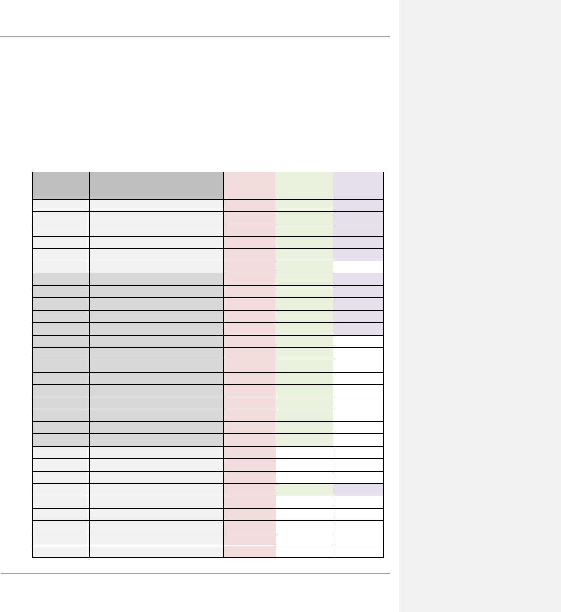
PMP 450 Planning Guide
• GUEST, who has no write permissions and only a limited view of General Status tab
From the factory default state, configure passwords for both the root and admin account at the
ADMINISTRATOR permission level, using the Account => Change Users Password tab. (If you configure only
one of these, then the other will still require no password for access into it and thus remain a security risk.) If you
are intent on configuring only one of them, delete the admin account. The root account is the only account that
CNUT uses to update the module.
After a password has been set for any ADMINISTRATOR-level account, initial access to the module GUI opens
the view of GUEST level.
Table 57 Identity-based user account permissions - AP
Menu
Option Menu Tab ADMIN INSTALLER TECH
Home
General Status
Session Status
Remote Subscribers
Event Log
Network Interface
Layer2 Neighbors
Configuration
General
IP
Radio
SNMP
Quality of Service (QoS)
Security
Time
VLAN
VLAN Membership
DiffServ
Protocol Filtering
Port Configuration
Syslog
Unit Settings
Statistics
Scheduler
SM Registration Failures
Bridge Control Block
Bridging Table
Ethernet
Radio
VLAN
Data VC
Throughput
1-128 pmp-0047 (March 2014)

PMP 450 Planning Guide
Filter
ARP
Overload
DHCP Relay
Pass Through Statistics
DNS Statistics
Tools
Link Capacity Test
OFDM Frame Calculator
Subscriber Configuration
Link Status
Remote Spectrum Analyzer
Sessions
DNS Test
AP Sessions
AP Authentication State Machine
Log
AP Authorization State Machine Log
EAP Radius Log
Accounts
User Authentication And Access
Tracking
Change User Password
Add User
Delete User
Quick Start
Quick Start
Region Settings
Radio Carrier Frequency
Synchronization
LAN IP Address
Review and Save Configuration
Copyright
Copyright Notices
Logoff
pmp-0047 (March 2014) 1-129
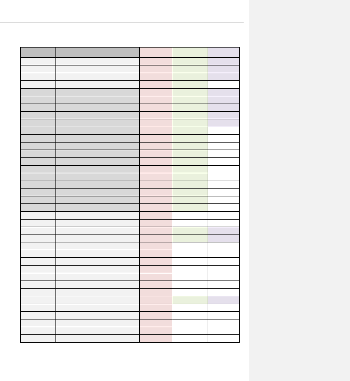
PMP 450 Planning Guide
Table 58 Identity-based user account permissions - SM
Menu Menu Tab ADMIN INSTALLER TECH
Home
General Status
Event Log
Network Interface
Layer2 Neighbors
Configuration
General
IP
Radio
SNMP
Quality of Service (QoS)
Security
VLAN
VLAN Membership
DiffServ
Protocol Filtering
Port Configuration
NAT
PPPoE
NAT Port Mapping
Syslog
Unit Settings
Statistics
Scheduler
Bridge Control Block
Bridging Table
Translation Table
Ethernet
Radio
VLAN
Data VC
Filter
NAT Stats
NAT DHCP
ARP
Overload
PPPoE Statistics
Peer Statistics
DNS Statistics
Syslog Statistics
1-130 pmp-0047 (March 2014)

PMP 450 Planning Guide
Tools
Spectrum Analyzer
Alignment
Link Capacity Test
AP Evaluation
OFDM Frame Calculator
BER Results
Alignment Tool
Link Status
DNS Test
Logs
NAT Table
SM Session
SM Authentication
SM Authorization
PPPoE Session Log
EAP Radius Log
Accounts
User Authentication and Access
Tracking
Change User Password
Add User
Delete User
PDA
Quick Status
Spectrum Results (PDA)
Information
AP Evaluation
AIM
Copyright
Copyright Notices
Logoff
Filtering protocols and ports
You can filter (block) specified protocols and ports from leaving the AP and SM and entering the network. This
protects the network from both intended and inadvertent packet loading or probing by network users. By keeping
the specified protocols or ports off the network, this feature also provides a level of protection to users from each
other.
Protocol and port filtering is set per AP/SM. Except for filtering of SNMP ports, filtering occurs as packets leave
the AP/SM. If an SM is configured to filter SNMP, then SNMP packets are blocked from entering the SM and,
thereby, from interacting with the SNMP portion of the protocol stack on the SM.
pmp-0047 (March 2014) 1-131

PMP 450 Planning Guide
Port Filtering with NAT Enabled
Where NAT is enabled on the SM, you can filter only the three user-defined ports. The following are example
situations in which you can configure port filtering where NAT is enabled.
• To block a subscriber from using FTP, you can filter Ports 20 and 21 (the FTP ports) for both the TCP and
UDP protocols.
• To block a subscriber from access to SNMP, you can filter Ports 161 and 162 (the SNMP ports) for both the
TCP and UDP protocols.
NOTE: In only the SNMP case, filtering occurs before the packet interacts with the protocol stack.
Protocol and Port Filtering with NAT Disabled
Where NAT is disabled on the SM, you can filter both protocols and the three user-defined ports. Using the check
boxes on the interface, you can either
• allow all protocols except those that you wish to block.
• block all protocols except those that you wish to allow.
You can allow or block any of the following protocols:
• PPPoE (Point to Point Protocol over Ethernet)
• Any or all of the following IPv4 (Internet Protocol version 4) protocols:
o SMB (Network Neighborhood)
o SNMP
o Up to 3 user-defined ports
o All other IPv4 traffic (see Figure 32)
o Uplink Broadcast
o ARP (Address Resolution Protocol)
o All others (see Figure 32)
1-132 pmp-0047 (March 2014)

PMP 450 Planning Guide
Figure 32 Categorical protocol filtering
BootP
Client
BootP
Server
SNMP IPv4
Multica
st
User
Defined
Port 1 SMB
User
Defined
Port 3
User
Defined
Port 2
PPPoE ARP
All
Others
All
Other
IPv4
The following are example situations in which you can configure protocol filtering where NAT is disabled:
• If you block a subscriber from only PPoE and SNMP, then the subscriber retains access to all other protocols
and all ports.
• If you block PPoE, IPv4, and Uplink Broadcast, and you also check the
All others selection, then only Address Resolution Protocol is not filtered.
pmp-0047 (March 2014) 1-133

PMP 450 Planning Guide
The ports that are filtered as a result of protocol selections in the Protocol Filtering tab of the SM are listed in Table
59.
Table 59 Ports filtered per protocol selections
Protocol Selected Port Filtered (Blocked)
SMB Destination Ports 137 TCP and UDP, 138 UDP, 139 TCP, 445 TCP
SNMP Destination Ports 161 TCP and UDP, 162 TCP and UDP
Bootp Client Source Port 68 UDP
Bootp Server Source Port 67 UDP
Port Lockdown
Cambium devices support access to various communication protocols and only the ports required for these
protocols are available for access by external entities. Operators may change the port numbers for these protocols
via the radio GUI or SNMP.
Table 60 Device default port numbers
Port
Usage
Port Usage
Device
21 FTP Listen Port AP, SM
80 HTTP Listen Port AP, SM
1812 Standard RADIUS port Destination Port AP
1813 Standard RADIUS accounting port Destination Port AP, SM
161 SNMP port Listen Port AP, SM
162 SNMP trap port Destination Port AP, SM
514 Syslog Destination Port AP, SM
Isolating SMs
In an AP, you can prevent SMs in the sector from directly communicating with each other. In CMMmicro Release
2.2 or later and the CMM4, you can prevent connected APs from directly communicating with each other, which
prevents SMs that are in different sectors of a cluster from communicating with each other.
In the AP, the SM Isolation parameter is available in the General tab of the Configuration web page. In the drop-
down menu for that parameter, you can configure the SM Isolation feature by any of the following selections:
• Disable SM Isolation (the default selection). This allows full communication between SMs.
• Block SM Packets from being forwarded. This prevents both multicast/broadcast and unicast SM-to-SM
communication.
1-134 pmp-0047 (March 2014)

PMP 450 Planning Guide
• Block and Forward SM Packets to Backbone. This not only prevents multicast/broadcast and unicast SM-to-
SM communication but also sends the packets, which otherwise would have been handled SM to SM, through
the Ethernet port of the AP.
In the CMMmicro and the CMM4, SM isolation treatment is the result of how you choose to manage the port-based
VLAN feature of the embedded switch, where you can switch all traffic from any AP to an uplink port that you
specify. However, this is not packet level switching. It is not based on VLAN IDs. See the VLAN Port
Configuration parameter in the dedicated user guide that supports the CMM product that you are deploying.
Filtering management through Ethernet
You can configure the SM to disallow any device that is connected to its Ethernet port from accessing the IP
address of the SM. If you set the Ethernet Access Control parameter to Enabled, then
• no attempt to access the SM management interface (by http, SNMP, ftp, or tftp) through Ethernet can succeed.
• any attempt to access the SM management interface over the air (by IP address, presuming that LAN1
Network Interface Configuration, Network Accessibility is set to Public, or by link from the Session Status
or Remote Subscribers tab in the AP) is unaffected.
Allowing management from only specified IP addresses
The Security tab of the Configuration web page in the AP and SM includes the IP Access Control parameter. You
can specify one, two, or three IP addresses that should be allowed to access the management interface (by HTTP,
SNMP, FTP, or TFTP).
If you select
• IP Access Filtering Disabled, then management access is allowed from any IP address, even if the Allowed
Source IP 1 to 3 parameters are populated.
• IP Access Filtering Enabled, and specify at least one address in the Allowed Source IP 1 to 3 parameter, then
management access is limited to the specified address(es).
Configuring management IP by DHCP
The IP tab in the Configuration web page of every radio contains a LAN1 Network Interface Configuration,
DHCP State parameter that, if enabled, causes the IP configuration (IP address, subnet mask, and gateway IP
address) to be obtained through DHCP instead of the values of those individual parameters. The setting of this
DHCP state parameter is also viewable, but is not settable, in the Network Interface tab of the Home page.
In the SM, this parameter is settable
• in the NAT tab of the Configuration web page, but only if NAT is enabled.
• in the IP tab of the Configuration web page, but only if the Network Accessibility parameter in the IP tab is set
to Public.
pmp-0047 (March 2014) 1-135

PMP 450 Planning Guide
Planning for airlink security
Cambium fixed wireless broadband IP systems employ the following form of encryption for security of the wireless
link:
• DES (Data Encryption Standard): An over-the-air link encryption option that uses secret 56-bit keys and 8
parity bits. DES performs a series of bit permutations, substitutions, and recombination operations on blocks of
data. DES encryption does not affect the performance or throughput of the system.
• AES (Advanced Encryption Standard): An over-the-air link encryption option that uses the Rijndael
algorithm and 128-bit keys to establish a higher level of security than DES. AES products are certified as
compliant with the Federal Information Processing Standards (FIPS 197) in the U.S.A.
Planning for RF Telnet Access Control
The RF Telnet Access feature restricts Telnet access to the AP from a device situated below a network SM
(downstream from the AP). This is a security enhancement to restrict RF-interface sourced AP access specifically
to the LAN1 IP address and LAN2 IP address (Radio Private Address, typically 192.168.101.[LUID]). This
restriction disallows unauthorized users from running Telnet commands on the AP that can change AP
configuration or modifying network-critical components such as routing and ARP tables.
Forwarding Downlink PPPoE PADI packets
The AP supports the control of forwarding of PPPoE PADI (PPPoE Active Discovery Initiation) packets. This
forwarding is configured on the AP GUI Configuration, Radio tab by parameter PPPoE PADI Downlink
Forwarding. When set to “Enabled”, the AP allows downstream and upstream transmission of PPPoE PADI
packets. When set to “Disabled”, the AP will NOT allow PPPoE PADI packets to be sent out of the AP RF
interface (downstream) but will allow PPPoE PADI packets to enter the RF interface (upstream) and exit the
Ethernet interface.
Planning for RADIUS integration
PMP 450 modules include support for the RADIUS (Remote Authentication Dial In User Service) protocol
supporting Authentication, Authorization, and Accounting (AAA).
RADIUS
Functions
RADIUS protocol support provides the following functions:
• SM Authentication allows only known SMs onto the network (blocking “rogue” SMs), and can be
configured to ensure SMs are connecting to a known network (preventing SMs from connecting to “rogue”
APs). RADIUS authentication is used for SMs, but is not used for APs. Cambium modules support EAP-
TTLS and EAP-MSCHAPv2 authentication methods.
1-136 pmp-0047 (March 2014)

PMP 450 Planning Guide
• SM Configuration: Configures authenticated SMs with MIR (Maximum Information Rate), CIR (Committed
Information Rate), High Priority, and VLAN (Virtual LAN) parameters from the RADIUS server when an SM
registers to an AP.
• SM Accounting provides support for RADIUS accounting messages for usage-based billing. This accounting
includes indications for subscriber session establishment, subscriber session disconnection, and bandwidth
usage per session for each SM that connects to the AP.
• Centralized AP and SM user name and password management allows AP and SM usernames and access
levels (Administrator, Installer, Technician) to be centrally administered in the RADIUS server instead of on
each radio and tracks access events (logon/logoff) for each username on the RADIUS server. This
accounting does not track and report specific configuration actions performed on radios or pull statistics
such as bit counts from the radios. Such functions require an Element Management System (EMS) such as
Cambium Networks Wireless Manager. This accounting is not the ability to perform accounting functions on
the subscriber/end user/customer account.
•
Framed IP
allows operators to use a RADIUS server to assign management IP addressing to SM modules
(framed IP address).
Planning for SNMP security
Canopy modules provide the following Configuration web page parameters in the SNMP tab. These govern SNMP
access from the manager to the agent:
• Community String, which specifies the password for security between managers and the agent.
• Accessing Subnet, which specifies the subnet mask that allows managers to poll the agents.
pmp-0047 (March 2014) 1-137

PMP 450 Planning Guide
Ordering components
This section describes how to select components for PMP 450 Greenfield network or PMP 450 network migration.
It specifies Cambium part numbers for PMP 450 components.
PMP 450 component part numbers
Table 61 PMP 450 components
Part Number Product Description
Sales Models
C024045A001A 2.4 GHz PMP 450 Connectorized Access Point, US/Canada Only, AES
C024045A002A 2.4 GHz PMP 450 Connectorized Access Point, US/Canada Only, DES
C024045C001A 2.4 GHz PMP 450 Subscriber Module, 4 Mbps
C024045C002A 2.4 GHz PMP 450 Subscriber Module, 10 Mbps
C024045C003A 2.4 GHz PMP 450 Subscriber Module, 20 Mbps
C024045C004A 2.4 GHz PMP 450 Subscriber Module, Uncapped
C024045C005A 2.4 GHz PMP 450 Connectorized Subscriber Module, 4 Mbps
C024045C006A 2.4 GHz PMP 450 Connectorized Subscriber Module, 10 Mbps
C024045C007A 2.4 GHz PMP 450 Connectorized Subscriber Module, 20 Mbps
C024045C008A 2.4 GHz PMP 450 Connectorized Subscriber Module, Uncapped
C035045A001A 3.5 GHz PMP 450 Connectorized Access Point, US/Canada Only, AES
C035045A002A 3.5 GHz PMP 450 Connectorized Access Point, US/Canada Only, DES
C035045C001A 3.5 GHz PMP 450 Subscriber Module, 4 Mbps
C035045C002A 3.5 GHz PMP 450 Subscriber Module, 10 Mbps
C035045C003A 3.5 GHz PMP 450 Subscriber Module, 20 Mbps
C035045C004A 3.5 GHz PMP 450 Subscriber Module, Uncapped
1-138 pmp-0047 (March 2014)

PMP 450 Planning Guide
C035045C005A 3.5 GHz PMP 450 Connectorized Subscriber Module, 4 Mbps
C035045C006A 3.5 GHz PMP 450 Connectorized Subscriber Module, 10 Mbps
C035045C007A 3.5 GHz PMP 450 Connectorized Subscriber Module, 20 Mbps
C035045C008A 3.5 GHz PMP 450 Connectorized Subscriber Module, Uncapped
C036045A001A 3.6 GHz PMP 450 Connectorized Access Point, US/Canada Only, AES
C036045A002A 3.6 GHz PMP 450 Connectorized Access Point, US/Canada Only, DES
C036045C001A 3.6 GHz PMP 450 Subscriber Module, 4 Mbps
C036045C002A 3.6 GHz PMP 450 Subscriber Module, 10 Mbps
C036045C003A 3.6 GHz PMP 450 Subscriber Module, 20 Mbps
C036045C004A 3.6 GHz PMP 450 Subscriber Module, Uncapped
C036045C005A 3.6 GHz PMP 450 Connectorized Subscriber Module, 4 Mbps
C036045C006A 3.6 GHz PMP 450 Connectorized Subscriber Module, 10 Mbps
C036045C007A 3.6 GHz PMP 450 Connectorized Subscriber Module, 20 Mbps
C036045C008A 3.6 GHz PMP 450 Connectorized Subscriber Module, Uncapped
C054045A001A 5 GHz PMP 450 Connectorized Access Point
C054045A002A 5 GHz PMP 450 Connectorized Access Point, US
C054045C005A 5 GHz PMP 450 Connectorized Subscriber Module, 4 Mbps
C054045C006A 5 GHz PMP 450 Connectorized Subscriber Module, 10 Mbps
C054045C007A 5 GHz PMP 450 Connectorized Subscriber Module, 20 Mbps
C054045C008A 5 GHz PMP 450 Connectorized Subscriber Module, Uncapped
AP Antenna Options
85009324001 5 GHz Antenna for 90 Degree Sector
85009325001 5 GHz Antenna for 60 Degree Sector
C024045D601A 2.4 GHz Dual Slant Antenna for 60 Degree Sector
pmp-0047 (March 2014) 1-139

PMP 450 Planning Guide
C030045D901A 3.5 GHz and 3.6 GHz Dual Slant Antenna for 90 Degree Sector
30009406002 N-type to N-type cable (16 inch length)
AP Optional
Equipment
ACPSSW-20A POWER SUPPLY,20W, 29.5V, 100-240VAC/50-60HZ
ACPSSW-21A POWER SUPPLY,20W,29.5V,100-240VAC/50-60HZ +C8 AC
ACPS120WA POWER SUPPLY,120W 30VDC AT 60C 100-240VAC EL5
600SSH SURGE PROTECTOR
SMMB2A UNIVERSAL MOUNTING BRACKET
1070CKHH CMM MICRO (OUTDOOR ENCLOSURE)
1090CKHH CMM4 W/RUGGEDIZED SWITCH AND GPS
1091HH CMM4 NO SWITCH
1092HH CMM4 RACK MOUNT ASSEMBLY
1096H UNIVERSAL GPS MODULE
SM Optional
Equipment
ACPSSW-09B POWER SUPPLY,13.6W, 29.5V, 100-240VAC/50-60HZ
ACPSSW-10B POWER SUPPLY,13.6W,29.5V,100-240VAC/50-60HZ+ARG
ACPSSW-11B POWER SUPPLY, 13.6W,29.5V,100-240VAC/50-60HZ+AUS
ACPSSW-12C POWER SUPPLY,ASSY,P/S,29.5V90-240VAC/50-60HZ PS
ACPSSW-13B POWER SUPPLY,13.6W,29.5V,100-240/50-60+FIXED US
ACPSSW-14A POWER SUPPLY,13.6W,29.5V,100-240VAC/50-60HZ+BRAZ
HK2022A 53CM OFFSET, REFLECTOR DISH KIT,4PK
SMMB1A UNIVERSAL MOUNTING KIT
600SSH SURGE PROTECTOR
1-140 pmp-0047 (March 2014)

PMP 450 Planning Guide
Upgrade Keys
C000045K002A PMP 450 4 TO 10 MBPS UPGRADE KEY
C000045K003A PMP 450 4 TO 20 MBPS UPGRADE KEY
C000045K004A PMP 450 4 TO Uncapped UPGRADE KEY
C000045K005A PMP 450 10 TO 20 MBPS UPGRADE KEY
C000045K006A PMP 450 10 TO Uncapped MBPS UPGRADE KEY
C000045K007A PMP 450 20 TO Uncapped MBPS UPGRADE KEY
Extended Warranty
SG00TS4009A PMP450 AP Extended Warranty, 1 Additional Year
SG00TS4017A PMP450 AP Extended Warranty, 2 Additional Years
SG00TS4025A PMP450 AP Extended Warranty, 4 Additional Years
SG00TS4010A PMP450 SM Extended Warranty, 1 Additional Year
SG00TS4018A PMP450 SM Extended Warranty, 2 Additional Years
SG00TS4026A PMP450 SM Extended Warranty, 4 Additional Years
Part Number Product Description
Sales Models
C024045A001A 2.4 GHz PMP 450 Connectorized Access Point
C024045A003A 2.4 GHz PMP 450 Connectorized Access Point, DES
C024045C001A 2.4 GHz PMP 450 Subscriber Module, 4 Mbps
C024045C002A 2.4 GHz PMP 450 Subscriber Module, 10 Mbps
C024045C003A 2.4 GHz PMP 450 Subscriber Module, 20 Mbps
pmp-0047 (March 2014) 1-141

PMP 450 Planning Guide
C024045C004A 2.4 GHz PMP 450 Subscriber Module, Uncapped
C024045C005A 2.4 GHz PMP 450 Connectorized Subscriber Module, 4 Mbps
C024045C006A 2.4 GHz PMP 450 Connectorized Subscriber Module, 10 Mbps
C024045C007A 2.4 GHz PMP 450 Connectorized Subscriber Module, 20 Mbps
C024045C008A 2.4 GHz PMP 450 Connectorized Subscriber Module, Uncapped
C035045A001A 3.5 GHz PMP 450 Connectorized Access Point
C035045A003A 3.5 GHz PMP 450 Connectorized Access Point, DES
C035045C001A 3.5 GHz PMP 450 Subscriber Module, 4 Mbps
C035045C002A 3.5 GHz PMP 450 Subscriber Module, 10 Mbps
C035045C003A 3.5 GHz PMP 450 Subscriber Module, 20 Mbps
C035045C004A 3.5 GHz PMP 450 Subscriber Module, Uncapped
C035045C005A 3.5 GHz PMP 450 Connectorized Subscriber Module, 4 Mbps
C035045C006A 3.5 GHz PMP 450 Connectorized Subscriber Module, 10 Mbps
C035045C007A 3.5 GHz PMP 450 Connectorized Subscriber Module, 20 Mbps
C035045C008A 3.5 GHz PMP 450 Connectorized Subscriber Module, Uncapped
C036045A001A 3.6 GHz PMP 450 Connectorized Access Point
C036045A003A 3.6 GHz PMP 450 Connectorized Access Point, DES
C036045C001A 3.6 GHz PMP 450 Subscriber Module, 4 Mbps
C036045C002A 3.6 GHz PMP 450 Subscriber Module, 10 Mbps
C036045C003A 3.6 GHz PMP 450 Subscriber Module, 20 Mbps
C036045C004A 3.6 GHz PMP 450 Subscriber Module, Uncapped
C036045C005A 3.6 GHz PMP 450 Connectorized Subscriber Module, 4 Mbps
C036045C006A 3.6 GHz PMP 450 Connectorized Subscriber Module, 10 Mbps
C036045C007A 3.6 GHz PMP 450 Connectorized Subscriber Module, 20 Mbps
1-142 pmp-0047 (March 2014)

PMP 450 Planning Guide
C036045C008A 3.6 GHz PMP 450 Connectorized Subscriber Module, Uncapped
C054045A001A 5 GHz PMP 450 Connectorized Access Point
C054045A002A 5 GHz PMP 450 Connectorized Access Point, US only
C054045C005A 5 GHz PMP 450 Connectorized Subscriber Module, 4 Mbps
C054045C006A 5 GHz PMP 450 Connectorized Subscriber Module, 10 Mbps
C054045C007A 5 GHz PMP 450 Connectorized Subscriber Module, 20 Mbps
C054045C008A 5 GHz PMP 450 Connectorized Subscriber Module, Uncapped
AP Antenna Options
85009324001 5 GHz Antenna for 90 Degree Sector
85009325001 5 GHz Antenna for 60 Degree Sector
C024045D601A 2.4 GHz Dual Slant Antenna for 60 Degree Sector
C030045D901A 3.5 GHz and 3.6 GHz Dual Slant Antenna for 90 Degree Sector
30009406002 N-type to N-type cable (16 inch length)
AP Optional
Equipment
ACPSSW-20A POWER SUPPLY,20W, 29.5V, 100-240VAC/50-60HZ
ACPSSW-21A POWER SUPPLY,20W,29.5V,100-240VAC/50-60HZ +C8 AC
ACPS120WA POWER SUPPLY,120W 30VDC AT 60C 100-240VAC EL5
600SSH SURGE PROTECTOR
SMMB2A UNIVERSAL MOUNTING BRACKET
1070CKHH CMM MICRO (OUTDOOR ENCLOSURE)
1090CKHH CMM4 W/RUGGEDIZED SWITCH AND GPS
1091HH CMM4 NO SWITCH
1092HH CMM4 RACK MOUNT ASSEMBLY
1096H UNIVERSAL GPS MODULE
pmp-0047 (March 2014) 1-143

PMP 450 Planning Guide
SM Optional
Equipment
ACPSSW-09B POWER SUPPLY,13.6W, 29.5V, 100-240VAC/50-60HZ
ACPSSW-10B POWER SUPPLY,13.6W,29.5V,100-240VAC/50-60HZ+ARG
ACPSSW-11B POWER SUPPLY, 13.6W,29.5V,100-240VAC/50-60HZ+AUS
ACPSSW-12C POWER SUPPLY,ASSY,P/S,29.5V90-240VAC/50-60HZ PS
ACPSSW-13B POWER SUPPLY,13.6W,29.5V,100-240/50-60+FIXED US
ACPSSW-14A POWER SUPPLY,13.6W,29.5V,100-240VAC/50-60HZ+BRAZ
HK2022A 53CM OFFSET, REFLECTOR DISH KIT,4PK
SMMB1A UNIVERSAL MOUNTING KIT
600SSH SURGE PROTECTOR
Upgrade Keys
C000045K002A PMP 450 4 TO 10 MBPS UPGRADE KEY
C000045K003A PMP 450 4 TO 20 MBPS UPGRADE KEY
C000045K004A PMP 450 4 TO Uncapped UPGRADE KEY
C000045K005A PMP 450 10 TO 20 MBPS UPGRADE KEY
C000045K006A PMP 450 10 TO Uncapped MBPS UPGRADE KEY
C000045K007A PMP 450 20 TO Uncapped MBPS UPGRADE KEY
Extended Warranty
SG00TS4009A PMP450 AP Extended Warranty, 1 Additional Year
SG00TS4017A PMP450 AP Extended Warranty, 2 Additional Years
SG00TS4025A PMP450 AP Extended Warranty, 4 Additional Years
SG00TS4010A PMP450 SM Extended Warranty, 1 Additional Year
SG00TS4018A PMP450 SM Extended Warranty, 2 Additional Years
SG00TS4026A PMP450 SM Extended Warranty, 4 Additional Years
1-144 pmp-0047 (March 2014)

PMP 450 Planning Guide List of Tables
Chapter 2: Legal information
This chapter provides legal notices including software license agreements.
Intentional or unintentional changes or modifications to the equipment must not be made unless under the express
consent of the party responsible for compliance. Any such modifications could void the user’s authority to
operate the equipment and will void the manufacturer’s warranty.
The following topics are described in this chapter:
• Cambium Networks end user license agreement on page 2-2
• Hardware warranty on page 2-10
• Limit of liability on page 2-11

PMP 450 Planning Guide Glossary
Cambium Networks end user license agreement
Acceptance of this agreement
In connection with Cambium’s delivery of certain proprietary software or products containing embedded or pre-
loaded proprietary software, or both, Cambium is willing to license this certain proprietary software and the
accompanying documentation to you only on the condition that you accept all the terms in this End User License
Agreement (“Agreement”).
IF YOU DO NOT AGREE TO THE TERMS OF THIS AGREEMENT, DO NOT USE THE PRODUCT OR
INSTALL THE SOFTWARE. INSTEAD, YOU MAY, FOR A FULL REFUND, RETURN THIS PRODUCT TO
THE LOCATION WHERE YOU ACQUIRED IT OR PROVIDE WRITTEN VERIFICATION OF DELETION
OF ALL COPIES OF THE SOFTWARE. ANY USE OF THE SOFTWARE, INCLUDING BUT NOT LIMITED
TO USE ON THE PRODUCT, WILL CONSTITUTE YOUR ACCEPTANCE TO THE TERMS OF THIS
AGREEMENT.
Definitions
In this Agreement, the word “Software” refers to the set of instructions for computers, in executable form and in
any media, (which may include diskette, CD-ROM, downloadable internet, hardware, or firmware) licensed to you.
The word “Documentation” refers to electronic or printed manuals and accompanying instructional aids licensed to
you. The word “Product” refers to Cambium’s fixed wireless broadband devices for which the Software and
Documentation is licensed for use.
Grant of license
Cambium Networks Limited (“Cambium”) grants you (“Licensee” or “you”) a personal, nonexclusive, non-
transferable license to use the Software and Documentation subject to the Conditions of Use set forth in
“Conditions of use” and the terms and conditions of this Agreement. Any terms or conditions relating to the
Software and Documentation appearing on the face or reverse side of any purchase order, purchase order
acknowledgment or other order document that are different from, or in addition to, the terms of this Agreement will
not be binding on the parties, even if payment is accepted.
Conditions of use
Any use of the Software and Documentation outside of the conditions set forth in this Agreement is strictly
prohibited and will be deemed a breach of this Agreement.
2-2 pmp-0047 (March 2014)

PMP 450 Planning Guide Glossary
1. Only you, your employees or agents may use the Software and Documentation. You will take all necessary steps
to insure that your employees and agents abide by the terms of this Agreement.
2. You will use the Software and Documentation (i) only for your internal business purposes; (ii) only as described
in the Software and Documentation; and (iii) in strict accordance with this Agreement.
3. You may use the Software and Documentation, provided that the use is in conformance with the terms set forth in
this Agreement.
4. Portions of the Software and Documentation are protected by United States copyright laws, international treaty
provisions, and other applicable laws. Therefore, you must treat the Software like any other copyrighted material
(for example, a book or musical recording) except that you may either: (i) make 1 copy of the transportable part of
the Software (which typically is supplied on diskette, CD-ROM, or downloadable internet), solely for back-up
purposes; or (ii) copy the transportable part of the Software to a PC hard disk, provided you keep the original solely
for back-up purposes. If the Documentation is in printed form, it may not be copied. If the Documentation is in
electronic form, you may print out 1 copy, which then may not be copied. With regard to the copy made for backup
or archival purposes, you agree to reproduce any Cambium copyright notice, and other proprietary legends
appearing thereon. Such copyright notice(s) may appear in any of several forms, including machine-readable form,
and you agree to reproduce such notice in each form in which it appears, to the extent it is physically possible to do
so. Unauthorized duplication of the Software or Documentation constitutes copyright infringement, and in the
United States is punishable in federal court by fine and imprisonment.
5. You will not transfer, directly or indirectly, any product, technical data or software to any country for which the
United States Government requires an export license or other governmental approval without first obtaining such
license or approval.
Title and restrictions
If you transfer possession of any copy of the Software and Documentation to another party outside of the terms of
this agreement, your license is automatically terminated. Title and copyrights to the Software and Documentation
and any copies made by you remain with Cambium and its licensors. You will not, and will not permit others to:
(i) modify, translate, decompile, bootleg, reverse engineer, disassemble, or extract the inner workings of the
Software or Documentation, (ii) copy the look-and-feel or functionality of the Software or Documentation;
(iii) remove any proprietary notices, marks, labels, or logos from the Software or Documentation; (iv) rent or
transfer all or some of the Software or Documentation to any other party without Cambium’s prior written consent;
or (v) utilize any computer software or hardware which is designed to defeat any copy protection device, should the
Software and Documentation be equipped with such a protection device. If the Software and Documentation is
provided on multiple types of media (such as diskette, CD-ROM, downloadable internet), then you will only use the
medium which best meets your specific needs, and will not loan, rent, lease, or transfer the other media contained in
the package without Cambium’s written consent. Unauthorized copying of the Software or Documentation, or
failure to comply with any of the provisions of this Agreement, will result in automatic termination of this license.
pmp-0047 (March 2014) 2-3

PMP 450 Planning Guide Glossary
Confidentiality
You acknowledge that all Software and Documentation contain valuable proprietary information and trade
secrets and that unauthorized or improper use of the Software and Documentation will result in irreparable harm to
Cambium for which monetary damages would be inadequate and for which Cambium will be entitled to immediate
injunctive relief. If applicable, you will limit access to the Software and Documentation to those of your employees
and agents who need to use the Software and Documentation for your internal business purposes, and you will take
appropriate action with those employees and agents to preserve the confidentiality of the Software and
Documentation, using the same degree of care to avoid unauthorized or improper disclosure as you use for the
protection of your own proprietary software, but in no event less than reasonable care.
You have no obligation to preserve the confidentiality of any proprietary information that: (i) was in the public
domain at the time of disclosure; (ii) entered the public domain through no fault of yours; (iii) was given to you free
of any obligation to keep it confidential; (iv) is independently developed by you; or (v) is disclosed as required by
law provided that you notify Cambium prior to such disclosure and provide Cambium with a reasonable
opportunity to respond.
Right to use Cambium’s name
Except as required in “Conditions of use”, you will not, during the term of this Agreement or thereafter, use any
trademark of Cambium, or any word or symbol likely to be confused with any Cambium trademark, either alone or
in any combination with another word or words.
Transfer
The Software and Documentation may not be transferred to another party without the express written consent of
Cambium, regardless of whether or not such transfer is accomplished by physical or electronic means. Cambium’s
consent may be withheld at its discretion and may be conditioned upon transferee paying all applicable license fees
and agreeing to be bound by this Agreement.
Updates
During the first 12 months after purchase of a Product, or during the term of any executed Maintenance and
Support Agreement for the Product, you are entitled to receive Updates. An “Update” means any code in any form
which is a bug fix, patch, error correction, or minor enhancement, but excludes any major feature added to the
Software. Updates are available for download at the support website.
Major features may be available from time to time for an additional license fee. If Cambium makes available to
you major features and no other end user license agreement is provided, then the terms of this Agreement will
apply.
2-4 pmp-0047 (March 2014)

PMP 450 Planning Guide Glossary
Maintenance
Except as provided above, Cambium is not responsible for maintenance or field service of the Software under
this Agreement.
Disclaimer
CAMBIUM DISCLAIMS ALL WARRANTIES OF ANY KIND, WHETHER EXPRESS, IMPLIED,
STATUTORY, OR IN ANY COMMUNICATION WITH YOU. CAMBIUM SPECIFICALLY DISCLAIMS
ANY WARRANTY INCLUDING THE IMPLIED WARRANTIES OF MERCHANTABILTY,
NONINFRINGEMENT, OR FITNESS FOR A PARTICULAR PURPOSE. THE SOFTWARE AND
DOCUMENTATION ARE PROVIDED “AS IS.” CAMBIUM DOES NOT WARRANT THAT THE SOFTWARE
WILL MEET YOUR REQUIREMENTS, OR THAT THE OPERATION OF THE SOFTWARE WILL BE
UNINTERRUPTED OR ERROR FREE, OR THAT DEFECTS IN THE SOFTWARE WILL BE CORRECTED.
CAMBIUM MAKES NO WARRANTY WITH RESPECT TO THE CORRECTNESS, ACCURACY, OR
RELIABILITY OF THE SOFTWARE AND DOCUMENTATION. Some jurisdictions do not allow the exclusion
of implied warranties, so the above exclusion may not apply to you.
Limitation of liability
THE TOTAL LIABILITY OF CAMBIUM UNDER THIS AGREEMENT FOR DAMAGES WILL NOT
EXCEED THE TOTAL AMOUNT PAID BY YOU FOR THE PRODUCT LICENSED UNDER THIS
AGREEMENT. IN NO EVENT WILL CAMBIUM BE LIABLE IN ANY WAY FOR INCIDENTAL,
CONSEQUENTIAL, INDIRECT, SPECIAL OR PUNITIVE DAMAGES OF ANY NATURE, INCLUDING
WITHOUT LIMITATION, LOST BUSINESS PROFITS, OR LIABILITY OR INJURY TO THIRD PERSONS,
WHETHER FORESEEABLE OR NOT, REGARDLESS OF WHETHER CAMBIUM HAS BEEN ADVISED OF
THE POSSIBLITY OF SUCH DAMAGES. Some jurisdictions do not permit limitations of liability for incidental
or consequential damages, so the above exclusions may not apply to you.
pmp-0047 (March 2014) 2-5

PMP 450 Planning Guide Glossary
U.S. government
If you are acquiring the Product on behalf of any unit or agency of the U.S. Government, the following applies.
Use, duplication, or disclosure of the Software and Documentation is subject to the restrictions set forth in
subparagraphs (c) (1) and (2) of the Commercial Computer Software – Restricted Rights clause at FAR 52.227-19
(JUNE 1987), if applicable, unless being provided to the Department of Defense. If being provided to the
Department of Defense, use, duplication, or disclosure of the Products is subject to the restricted rights set forth in
subparagraph (c) (1) (ii) of the Rights in Technical Data and Computer Software clause at DFARS 252.227-7013
(OCT 1988), if applicable. Software and Documentation may or may not include a Restricted Rights notice, or
other notice referring specifically to the terms and conditions of this Agreement. The terms and conditions of this
Agreement will each continue to apply, but only to the extent that such terms and conditions are not inconsistent
with the rights provided to you under the aforementioned provisions of the FAR and DFARS, as applicable to the
particular procuring agency and procurement transaction.
Term of license
Your right to use the Software will continue in perpetuity unless terminated as follows. Your right to use the
Software will terminate immediately without notice upon a breach of this Agreement by you. Within 30 days after
termination of this Agreement, you will certify to Cambium in writing that through your best efforts, and to the best
of your knowledge, the original and all copies, in whole or in part, in any form, of the Software and all related
material and Documentation, have been destroyed, except that, with prior written consent from Cambium, you may
retain one copy for archival or backup purposes. You may not sublicense, assign or transfer the license or the
Product, except as expressly provided in this Agreement. Any attempt to otherwise sublicense, assign or transfer
any of the rights, duties or obligations hereunder is null and void.
Governing law
This Agreement is governed by the laws of the United States of America to the extent that they apply and otherwise
by the laws of the State of Illinois.
Assignment
This agreement may not be assigned by you without Cambium’s prior written consent.
Survival of provisions
The parties agree that where the context of any provision indicates an intent that it survives the term of this
Agreement, then it will survive.
2-6 pmp-0047 (March 2014)

PMP 450 Planning Guide Glossary
Entire agreement
This agreement contains the parties’ entire agreement regarding your use of the Software and may be amended
only in writing signed by both parties, except that Cambium may modify this Agreement as necessary to comply
with applicable laws.
Third party software
The software may contain one or more items of Third-Party Software supplied by other third-party suppliers. The
terms of this Agreement govern your use of any Third-Party Software UNLESS A SEPARATE THIRD-PARTY
SOFTWARE LICENSE IS INCLUDED, IN WHICH CASE YOUR USE OF THE THIRD-PARTY SOFTWARE
WILL THEN BE GOVERNED BY THE SEPARATE THIRD-PARTY LICENSE.
ZLIB Copyright Notice
Copyright © 1995-1998 Jean-loup Gailly and Mark Adler
This software is provided 'as-is', without any express or implied warranty. In no event will the authors be held liable
for any damages arising from the use of this software.
Permission is granted to anyone to use this software for any purpose, including commercial applications, and to
alter it and redistribute it freely, subject to the following restrictions:
1. The origin of this software must not be misrepresented; you must not claim that you wrote the original software.
If you use this software in a product, an acknowledgment in the product documentation would be appreciated but is
not required.
2. Altered source versions must be plainly marked as such, and must not be misrepresented as being the original
software.
3. This notice may not be removed or altered from any source distribution.
Jean-loup Gailly
jloup@gzip.org
Mark Adler
madler@alumni.caltech.edu
pmp-0047 (March 2014) 2-7

PMP 450 Planning Guide Glossary
Modernizr Copyright Notice
MIT License
Copyright © 2009-2010 Faruk Ates
Permission is hereby granted, free of charge, to any person obtaining a copy of this software and associated
documentation files (the "Software"), to deal in the Software without restriction, including without limitation the
rights to use, copy, modify, merge, publish, distribute, sublicense, and/or sell copies of the Software, and to permit
persons to whom the Software is furnished to do so, subject to the following conditions: The above copyright notice
and this permission notice shall be included in all copies or substantial portions of the Software.
THE SOFTWARE IS PROVIDED "AS IS", WITHOUT WARRANTY OF ANY KIND, EXPRESS OR IMPLIED,
INCLUDING BUT NOT LIMITED TO THE WARRANTIES OF MERCHANTABILITY, FITNESS FOR A
PARTICULAR PURPOSE AND NONINFRINGEMENT. IN NO EVENT SHALL THE AUTHORS OR
COPYRIGHT HOLDERS BE LIABLE FOR ANY CLAIM, DAMAGES OR OTHER LIABILITY, WHETHER
IN AN ACTION OF CONTRACT, TORT OR OTHERWISE, ARISING FROM, OUT OF OR IN CONNECTION
WITH THE SOFTWARE OR THE USE OR OTHER DEALINGS IN THE SOFTWARE.
BSD License
Copyright © 2010, Faruk Ates All rights reserved. Redistribution and use in source and binary forms, with or
without modification, are permitted provided that the following conditions are met:
Redistributions of source code must retain the above copyright notice, this list of conditions and the following
disclaimer.
Redistributions in binary form must reproduce the above copyright notice, this list of conditions and the following
disclaimer in the documentation and/or other materials provided with the distribution.
Neither the name of the Organization nor the names of its contributors may be used to endorse or promote products
derived from this software without specific prior written permission.
THIS SOFTWARE IS PROVIDED BY THE COPYRIGHT HOLDERS AND CONTRIBUTORS "AS IS" AND
ANY EXPRESS OR IMPLIED WARRANTIES, INCLUDING, BUT NOT LIMITED TO, THE IMPLIED
WARRANTIES OF MERCHANTABILITY AND FITNESS FOR A PARTICULAR PURPOSE ARE
DISCLAIMED. IN NO EVENT SHALL COPYRIGHT HOLDER BE LIABLE FOR ANY DIRECT, INDIRECT,
INCIDENTAL, SPECIAL, EXEMPLARY, OR CONSEQUENTIAL DAMAGES (INCLUDING, BUT NOT
LIMITED TO, PROCUREMENT OF SUBSTITUTE GOODS OR SERVICES; LOSS OF USE, DATA, OR
PROFITS; OR BUSINESS INTERRUPTION) HOWEVER CAUSED AND ON ANY THEORY OF LIABILITY,
WHETHER IN CONTRACT, STRICT LIABILITY, OR TORT (INCLUDING NEGLIGENCE OR OTHERWISE)
ARISING IN ANY WAY OUT OF THE USE OF THIS SOFTWARE, EVEN IF ADVISED OF THE
POSSIBILITY OF SUCH DAMAGE.
D3 Copyright Notice
Copyright (c) 2013, Michael Bostock All rights reserved.
• Redistribution and use in source and binary forms, with or without modification, are permitted provided that
the following conditions are met:
• Redistributions of source code must retain the above copyright notice, this list of conditions and the following
disclaimer.
• Redistributions in binary form must reproduce the above copyright notice, this list of conditions and the
following disclaimer in the documentation and/or other materials provided with the distribution.
2-8 pmp-0047 (March 2014)

PMP 450 Planning Guide Glossary
• The name Michael Bostock may not be used to endorse or promote products derived from this software without
specific prior written permission.
THIS SOFTWARE IS PROVIDED BY THE COPYRIGHT HOLDERS AND CONTRIBUTORS "AS IS" AND
ANY EXPRESS OR IMPLIED WARRANTIES, INCLUDING, BUT NOT LIMITED TO, THE IMPLIED
WARRANTIES OF MERCHANTABILITY AND FITNESS FOR A PARTICULAR PURPOSE ARE
DISCLAIMED. IN NO EVENT SHALL MICHAEL BOSTOCK BE LIABLE FOR ANY DIRECT, INDIRECT,
INCIDENTAL, SPECIAL, EXEMPLARY, OR CONSEQUENTIAL DAMAGES (INCLUDING, BUT NOT
LIMITED TO, PROCUREMENT OF SUBSTITUTE GOODS OR SERVICES; LOSS OF USE, DATA, OR
PROFITS; OR BUSINESS INTERRUPTION) HOWEVER CAUSED AND ON ANY THEORY OF LIABILITY,
WHETHER IN CONTRACT, STRICT LIABILITY, OR TORT (INCLUDING NEGLIGENCE OR OTHERWISE)
ARISING IN ANY WAY OUT OF THE USE OF THIS SOFTWARE, EVEN IF ADVISED OF THE
POSSIBILITY OF SUCH DAMAGE.
pmp-0047 (March 2014) 2-9

PMP 450 Planning Guide Glossary
Hardware warranty
Cambium’s standard hardware warranty is for one (1) year from date of shipment from Cambium or a Cambium
Point-To-Point Distributor. Cambium warrants that hardware will conform to the relevant published specifications
and will be free from material defects in material and workmanship under normal use and service. Cambium shall
within this time, at its own option, either repair or replace the defective product within thirty (30) days of receipt of
the defective product. Repaired or replaced product will be subject to the original warranty period but not less than
thirty (30) days.
2-10 pmp-0047 (March 2014)

PMP 450 Planning Guide Glossary
Limit of liability
IN NO EVENT SHALL CAMBIUM NETWORKS BE LIABLE TO YOU OR ANY OTHER PARTY FOR ANY
DIRECT, INDIRECT, GENERAL, SPECIAL, INCIDENTAL, CONSEQUENTIAL, EXEMPLARY OR OTHER
DAMAGE ARISING OUT OF THE USE OR INABILITY TO USE THE PRODUCT (INCLUDING, WITHOUT
LIMITATION, DAMAGES FOR LOSS OF BUSINESS PROFITS, BUSINESS INTERRUPTION, LOSS OF
BUSINESS INFORMATION OR ANY OTHER PECUNIARY LOSS, OR FROM ANY BREACH OF
WARRANTY, EVEN IF CAMBIUM HAS BEEN ADVISED OF THE POSSIBILITY OF SUCH DAMAGES.
(Some states do not allow the exclusion or limitation of incidental or consequential damages, so the above exclusion
or limitation may not apply to you.) IN NO CASE SHALL CAMBIUM’S LIABILITY EXCEED THE AMOUNT
YOU PAID FOR THE PRODUCT.
pmp-0047 (March 2014) 2-11

PMP 450 Planning Guide Glossary
Chapter 3: Reference information
This chapter contains reference information and regulatory notices that apply to the PMP 450 Series products.
The following topics are described in this chapter:
• Equipment specifications on page 3-2 contains specifications of the AP, SM and other equipment required for
PMP 450 installations.
• Wireless specifications on page 3-10 contains specifications of the PMP 450 wireless interface, including RF
bands, channel width and link loss.
• Data network specifications on page 3-11 contains specifications of the PMP 450 Ethernet interface.
• Compliance with safety standards on page 3-12 lists the safety specifications against which the PMP 450 has
been tested and certified. It also describes how to keep RF exposure within safe limits.
• Compliance with radio regulations on page 3-17 describes how the PMP 450 complies with the radio
regulations that are enforced in various countries.
• Notifications on page 3-42 has notifications made to regulatory bodies for the PMP 450.

PMP 450 Planning Guide Glossary
Equipment specifications
This section contains specifications of the AP, SM, associated supplies required for PMP 450 installations.
AP specifications
The PMP 450 AP conforms to the specifications listed in Table 62. These specifications apply to all PMP 450
product variants (except where noted).
Table 62 Connectorized AP physical specifications
Category Specification
Product
Model
Number
2.4 GHz C024045A001A, C024045A003A
3.5 GHz C035045A001A, C035045A002A, C035045A003A, C035045A004A
3.6 GHz C036045A001A, C036045A002A, C036045A003A, C036045A004A
5 GHz C054045A001A, C054045A002A, C054045A003A
Spectrum
Channel
Spacing
5 MHz
10 MHz
20 MHz
channel
bandwidth
Configurable on 2.5 MHz increments (2.4GHz, 5 GHz)
Configurable on 50 kHz increments (3.5 GHz and 3.6 GHz)
Frequency
Range
2.4 GHz 2400 – 2483.5 MHz
3.5 GHz 3300 – 3600 MHz (dependent upon Region Code setting)
3.6 GHz 3650 – 3700 MHz (dependent upon Region Code setting)
5 GHz 5470 – 5875 MHz (dependent upon Region Code setting)
Channel Width 5 MHz (2.4 GHz, 3.5 GHz, 3.6 GHz and 5.8 GHz only), 10 MHz or 20 MHz
Interface
MAC (Media Access
Control) Layer
Cambium Proprietary
Physical Layer 2x2 MIMO OFDM
Ethernet Interface 10/100BaseT, half/full duplex, rate auto negotiated (802.3 compliant)
Protocols Used IPv4, UDP, TCP, IP, ICMP, SNMP, HTTP, FTP, RADIUS
3-2 pmp-0047 (March 2014)

PMP 450 Planning Guide Glossary
Category Specification
Network Management HTTP, FTP, SNMP v2c, Syslog
VLAN 802.1ad (DVLAN Q-inQ), 802.1Q with 802.1p priority, dynamic port VID
Performance
Nominal
Receive
Sensitivity
(w/ FEC) @
5 MHz
Channel,
Single
Branch
2.4 GHz OFDM: 1x = -91 dBm, 2x = -91 dBm, 4x = -86 dBm, 6x = -78 dBm, 8x = -68
dBm
3.5 GHz OFDM: 1x = -92 dBm, 2x = -92 dBm, 4x = -86 dBm, 6x = -80 dBm, 8x = -73
dBm
3.6 GHz OFDM: 1x = -92 dBm, 2x = -92 dBm, 4x = -86 dBm, 6x = -80 dBm, 8x = -73
dBm
5.4 GHz OFDM: 1x = -90 dBm, 2x = -90 dBm, 4x = -84 dBm, 6x = -80 dBm, 8x = -64
dBm
5.8 GHz OFDM: 1x = -91 dBm, 2x = -91 dBm, 4x = -85 dBm, 6x = -79 dBm, 8x = -69
dBm
Nominal
Receive
Sensitivity
(w/ FEC) @
10 MHz
Channel,
Single
Branch
2.4 GHz OFDM: 1x = -90 dBm, 2x = -90 dBm, 4x = -83 dBm, 6x = -76 dBm, 8x = -66
dBm
3.5 GHz OFDM: 1x = -90 dBm, 2x = -90 dBm, 4x = -83 dBm, 6x = -77 dBm, 8x = -70
dBm
3.6 GHz OFDM: 1x = -90 dBm, 2x = -90 dBm, 4x = -83 dBm, 6x = -77 dBm, 8x = -70
dBm
5.4 GHz OFDM: 1x = -88 dBm, 2x = -88 dBm, 4x = -82 dBm, 6x = -75 dBm, 8x = -62
dBm
5.8 GHz OFDM: 1x = -90 dBm, 2x = -90 dBm, 4x = -83 dBm, 6x = -76 dBm, 8x = -64
dBm
Nominal
Receive
Sensitivity
(w/ FEC) @
20 MHz
Channel,
Single
Branch
2.4 GHz OFDM: 1x = -86 dBm, 2x = -86 dBm, 4x = -80 dBm, 6x = -73 dBm, 8x = -66
dBm
3.5 GHz OFDM: 1x = -87 dBm, 2x = -87 dBm, 4x = -80 dBm, 6x = -73 dBm, 8x = -66
dBm
3.6 GHz OFDM: 1x = -87 dBm, 2x = -87 dBm, 4x = -80 dBm, 6x = -73 dBm, 8x = -66
dBm
5.4 GHz OFDM: 1x = -86 dBm, 2x = -86 dBm, 4x = -79 dBm, 6x = -72 dBm, 8x = -61
dBm
5.8 GHz OFDM: 1x = -87 dBm, 2x = -87 dBm, 4x = -80 dBm, 6x = -72 dBm, 8x = -62
dBm
pmp-0047 (March 2014) 3-3

PMP 450 Planning Guide Glossary
Category Specification
Maximum
Deployment
Range
2.4 GHz Up to 64 km (40 mi)
3.5 GHz Up to 64 km (40 mi)
3.6 GHz Up to 64 km (40 mi)
5 GHz Up to 40 km (25 mi)
Subscribers Per Sector Up to 238
ARQ Yes
Cyclic Prefix 1/16
Modulation Levels
(Adaptive)
QPSK, QPSK (MIMO-B), 16-QAM (MIMO-B), 64-QAM (MIMO-B), 256-
QAM (MIMO-B)
Latency 3 - 5 ms
Packets Per Second 12, 500
GPS Synchronization Yes, via CMM3, CMM4, or UGPS
Quality of Service Diffserv QoS
Link Budget
Combined Transmit
Power
-30 to +22 dBm (to EIRP limit by region) in 1 dB-configurable intervals (2.4
GHz, 5 GHz)
-30 to +25 dBm (to EIRP limit by region) in 1 dB-configurable intervals (3.5
GHz, 3.6 GHz)
Antenna
Gain
2.4 GHz 17 dBi Dual Slant
3.5 GHz 17 dBi Dual Slant
3.6 GHz 17 dBi Dual Slant
5 GHz 17 dBi Horizontal and Vertical
Maximum Transmit
Power
22 dBm combined OFDM (2.4GHz, 5 GHz)
25 dBm combined OFDM (3.5 GHz, 3.6 GHz)
Physical
Wind
Loading
2.4 GHz 216 km/hour (135 mi/hour)
3.5 GHz 216 km/hour (135 mi/hour)
3.6 GHz 216 km/hour (135 mi/hour)
5 GHz 190 km/hour (118 mi/hour)
3-4 pmp-0047 (March 2014)

PMP 450 Planning Guide Glossary
Category Specification
Antenna Connection 50 ohm, N-type
Environmental IP67
Temperature -40ºC to +55ºC (-40ºF to +131ºF)
Weight 2.4 GHz 15 kg (33 lbs) with antenna
2.5 kg (5.5 lbs) without antenna
3.5 GHz 15 kg (33 lbs) with antenna
2.5 kg (5.5 lbs) without antenna
3.6 GHz 15 kg (33 lbs) with antenna
2.5 kg (5.5 lbs) without antenna
5 GHz 5.9 kg (13 lbs) with antenna
2.5 kg (5.5 lbs) without antenna
Dimensions
(H x W x
D)
2.4 GHz Radio: 27 x 21 x 7 cm (10.6” x 8.3” x 2.8”)
Antenna: 112.2 x 24.5 x 11.7 cm (44.2” x 9.6” x 4.6”)
3.5 GHz 15 kg (33 lbs) with antenna
2.5 kg (5.5 lbs) without antenna
3.6 GHz 15 kg (33 lbs) with antenna
2.5 kg (5.5 lbs) without antenna
5 GHz Radio: 27 x 21 x 7 cm (10.6” x 8.3” x 2.8”)
Antenna: 51 x 13 x 7.3 cm (20.2” x 5.1” x 2.9”)
Maximum Power
Consumption
14 W
Input Voltage 22 to 32 VDC
Security
Encryption 56-bit DES, AES
Certifications
FCC ID Z8H89FT0002 (5.4, 5.8 GHz)
Z8H89FT0004 (2.4 GHz)
Z8H89FT0010 (3.6 GHz)
Industry Canada Cert 109W-0002 (5.4, 5.8 GHz)
109W-0004 (2.4 GHz)
109W-0008 (3.5 GHz)
109W-0010 (3.6 GHz)
pmp-0047 (March 2014) 3-5


PMP 450 Planning Guide Glossary
SM specifications
The PMP 450 SM conforms to the specifications listed in
Table 63. These specifications apply to all PMP 450 product variants.
Table 63 SM physical specifications
Category Specification
Product
Model
Number
2.4 GHz C024045C001A, C024045C002A, C024045C003A, C024045C004A,
C024045C005A, C024045C006A, C024045C007A, C024045C008A
3.5 GHz C035045C001A, C035045C002A, C035045C003A, C035045C004A,
C035045C005A, C035045C006A, C035045C007A, C035045C008A
3.6 GHz C036045C001A, C036045C002A, C036045C003A, C036045C004A,
C036045C005A, C036045C006A, C036045C007A, C036045C008A
5 GHz C054045C001A, C054045C002A, C054045C003A, C054045C004A,
C054045C005A, C054045C006A, C054045C007A, C054045C008A,
Spectrum
Channel
Spacing
5 MHz
10MHz, 20
MHz channel
bandwidth
Configurable on 2.5 MHz increments (2.4GHz, 5 GHz)
Configurable on 50 kHz increments (3.5 GHz, 3.6 GHz)
Frequency
Range
2.4 GHz 2400 – 2483.5 MHz
3.5 GHz 3300 – 3600 MHz (dependent upon Region Code setting)
3.6 GHz 3650 – 3700 MHz (dependent upon Region Code setting)
5 GHz 5470 – 5875 MHz (dependent upon Region Code setting)
Channel Width 5 MHz (2.4 GHz, 3.5GHz and 5.8 GHz only), 10 MHz or 20 MHz
Interface
MAC (Media Access
Control) Layer
Cambium Proprietary
Physical Layer 2x2 MIMO OFDM
Ethernet Interface 10/100BaseT, half/full duplex, rate auto negotiated (802.3 compliant)
Protocols Used IPv4, UDP, TCP, IP, ICMP, SNMP, HTTP, FTP, RADIUS
Network Management HTTP, FTP, SNMP v2c, Syslog
pmp-0047 (March 2014) 3-7

PMP 450 Planning Guide Glossary
Category Specification
VLAN 802.1ad (DVLAN Q-in-Q), 802.1Q with 802.1p priority, dynamic port VID
Performance
Maximum
Deployment
Range
2.4 GHz Up to 64 km (40 mi) with reflector dish
3.5 GHz Up to 40 km (25 mi) with reflector dish
3.6 GHz Up to 40 km (25 mi) with reflector dish
5 GHz Up to 40 km (25 mi) with reflector dish
ARQ Yes
Cyclic Prefix 1/16
Modulation Levels
(Adaptive)
1x = QPSK, 2x = QPSK-MIMO-B, 4x = 16-QAM-MIMO-B, 6x = 64-
QAM-MIMO-B, 8x = 256-QAM-MIMO-B
Latency 3 - 5 ms
GPS Synchronization Yes
Quality of Service Diffserv QoS
Link Budget
Antenna Beam Width 55º azimuth, 55º elevation (both horizontal and vertical)
Combined Transmit Power -30 to +22 dBm (to EIRP limit by region) – 2.4 GHz, 5 GHz
-30 to +25 dBm (to EIRP limit by region) – 3.5 GHz, 3.6 GHz
Antenna
Gain
2.4 GHz 7 dBi Dual Slant, integrated patch
3.5 GHz 8 dBi Dual Slant, integrated patch
3.6 GHz 8 dBi Dual Slant, integrated patch
5 GHz 9 dBi H+V, integrated patch
Maximum Transmit Power 22 dBm combined (2.4 GHz, 5 GHz)
25 dBm combined (3.5 GHz, 3.6 GHz)
Reflector
Gain
2.4 GHz +12 dBi
3.5 GHz +11 dBi
3.6 GHz +11 dBi
5 GHz +14 dBi
CLIP Gain (5 GHz only) +8 dBi
3-8 pmp-0047 (March 2014)

PMP 450 Planning Guide Glossary
Category Specification
LENS Gain (5 GHz only) +5.5 dBi
Physical
Wind Loading 190 km/hour (118 mi/hour)
Environmental IP55
Temperature -40ºC to +55ºC (-40ºF to +131ºF)
Weight 0.45 kg (1 lb)
Dimensions (H x W x D) 30 x 9 x 9 cm (11.75” x 3.4” x 3.4”)
Maximum Power
Consumption
12 W
Input Voltage 20 - 32 VDC
Security
Encryption 56-bit DES, AES
Certifications
FCC ID Z8H89FT0001 (5.4, 5.8 GHz)
Z8H89FT0003 (2.4 GHz)
Z8H89FT0009 (3.6 GHz)
Industry Canada Cert 109W-0001 (5.4, 5.8 GHz)
109W-0003 (2.4 GHz)
109W-0007 (3.5 GHz)
109W-0009 (3.6 GHz)
CE EN 301 893 v1.6.1 (5.4 GHz)
EN 302 502 v1.2.1 (5.8 GHz)
pmp-0047 (March 2014) 3-9
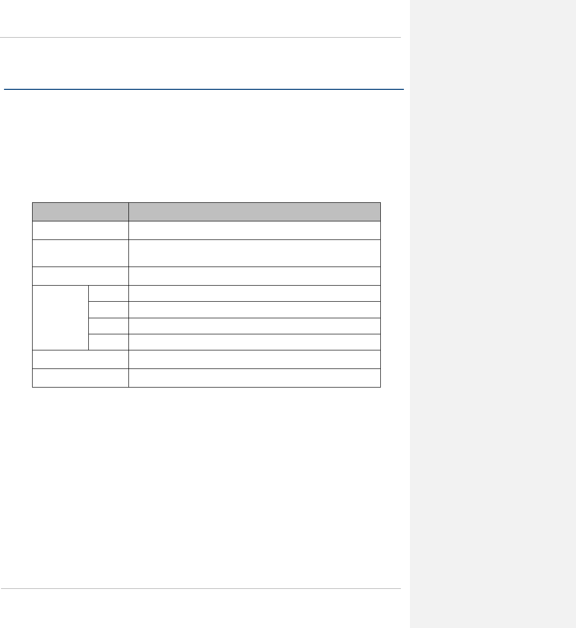
PMP 450 Planning Guide Glossary
Wireless specifications
This section contains specifications of the PMP 450 wireless interface. These specifications include RF bands,
channel bandwidth, spectrum settings, maximum power and link loss.
General wireless specifications
Table 64 lists the wireless specifications that apply to all PMP 450 variants.
Table 64 PMP 450 wireless specifications
Item Specification
Channel selection Manual selection (fixed frequency).
Manual power control To avoid interference to other users of the band, maximum power can be set
lower than the default power limit.
Duplex scheme Adaptive TDD
Range 2.4 GHz 40 mi / 64 km
3.5 GHz 40 mi / 64 km
3.6 GHz 40 mi / 64 km
5 GHz 25 mi / 40 km
Over-the-air encryption DES, AES
Error Correction FEC
3-10 pmp-0047 (March 2014)
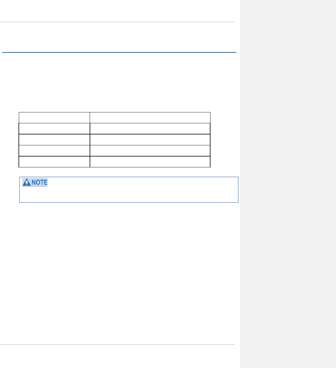
PMP 450 Planning Guide Glossary
Data network specifications
This section contains specifications of the PMP 450 Ethernet interface.
Ethernet interface
The PMP 450 Ethernet port conforms to the specifications listed in Table 65.
Table 65 PMP 450 Ethernet bridging specifications
Ethernet Bridging Specification
Protocol IEEE 802.3 compatible
QoS IEEE 802.1p, IEEE 802.1Q, IEEE 802.1ad, DSCP IPv4
Interface 10/100/BaseT, half/full duplex, rate auto negotiated
Maximum Ethernet Frame Size 1714 Bytes
Practical Ethernet rates will depend on network configuration, higher layer protocols and platforms used.
Over the air throughput is restricted to the rate of the Ethernet interface at the receiving end of the link.
pmp-0047 (March 2014) 3-11
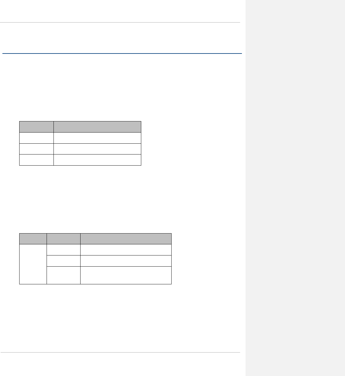
PMP 450 Planning Guide Glossary
Compliance with safety standards
This section lists the safety specifications against which the PMP 450 has been tested and certified. It also describes
how to keep RF exposure within safe limits.
Electrical safety compliance
The PMP 450 hardware has been tested for compliance to the electrical safety specifications listed in Table 66.
Table 66 PMP 450 safety compliance specifications
Region Specification
USA UL 60950
Canada CSA C22.2 No.60950
International CB certified & certificate to IEC 60950
Electromagnetic compatibility (EMC) compliance
Table 67 lists the EMC specification type approvals that have been granted for PMP 450.
Table 67 EMC emissions compliance
Variant Region Specification (Type Approvals)
PMP 450 USA FCC Part 15 Class B
Canada RSS Gen and RSS 210
International EN 301 489-1 V1.9.2
EN 301 489-17 V2.1.1
3-12 pmp-0047 (March 2014)

PMP 450 Planning Guide Glossary
Human exposure to radio frequency energy
Standards
Relevant standards (USA and EC) applicable when working with RF equipment are:
• ANSI IEEE C95.1-1991, IEEE Standard for Safety Levels with Respect to Human Exposure to Radio
Frequency Electromagnetic Fields, 3 kHz to 300 GHz.
• Council recommendation of 12 July 1999 on the limitation of exposure of the general public to electromagnetic
fields (0 Hz to 300 GHz) (1999/519/EC) and respective national regulations.
• Directive 2004/40/EC of the European Parliament and of the Council of 29 April 2004 on the minimum health
and safety requirements regarding the exposure of workers to the risks arising from physical agents
(electromagnetic fields) (18th individual Directive within the meaning of Article 16(1) of Directive
89/391/EEC).
• US FCC limits for the general population. See the FCC web site at http://www.fcc.gov, and the policies,
guidelines, and requirements in Part 1 of Title 47 of the Code of Federal Regulations, as well as the guidelines
and suggestions for evaluating compliance in FCC OET Bulletin 65.
• Health Canada limits for the general population. See the Health Canada web site at http://www.hc-
sc.gc.ca/ewh-semt/pubs/radiation/99ehd-dhm237/limits-limites_e.html and Safety Code 6.
• EN 50383:2002 Basic standard for the calculation and measurement of electromagnetic field strength and SAR
related to human exposure from radio base stations and fixed terminal stations for wireless telecommunication
systems (110 MHz - 40 GHz).
• BS EN 50385:2002 Product standard to demonstrate the compliances of radio base stations and fixed terminal
stations for wireless telecommunication systems with the basic restrictions or the reference levels related to
human exposure to radio frequency electromagnetic fields (110 MHz – 40 GHz) – general public.
• ICNIRP (International Commission on Non-Ionizing Radiation Protection) guidelines for the general public.
See the ICNIRP web site at http://www.icnirp.de/ and Guidelines for Limiting Exposure to Time-Varying
Electric, Magnetic, and Electromagnetic Fields.
Power density exposure limit
Install the radios for the PMP 450 family of PMP wireless solutions so as to provide and maintain the minimum
separation distances from all persons.
The applicable power density exposure limit from the standards (see Human exposure to radio frequency energy on
page 3-13) is:
• 10 W/m2 for RF energy in the 2.4, 3.5GHz, 3.6 GHz, 5.4-GHz and 5.8-GHz frequency bands.
pmp-0047 (March 2014) 3-13
PMP 450 Planning Guide Glossary
Calculation of power density
The following calculation is based on the ANSI IEEE C95.1-1991 method, as that provides a worst case analysis.
Details of the assessment to EN50383:2002 can be provided, if required.
Peak power density in the far field of a radio frequency point source is calculated as follows:
Where: Is:
S power density in W/m2
P maximum average transmit power capability
of the radio, in W
G total Tx gain as a factor, converted from dB
d distance from point source, in m
Rearranging terms to solve for distance yields:
Calculated distances and power compliance margins
Table 68 shows calculated minimum separation distances, recommended distances and resulting margins for each
frequency band and antenna combination. These are conservative distances that include compliance margins. At
these and greater separation distances, the power density from the RF field is below generally accepted limits for
the general population.
PMP 450 equipment adheres to all applicable EIRP limits for transmit power when operating in MIMO mode.
Separation distances and compliance margins include compensation for both transmitters.
Explanation of terms used in Table 68:
Tx burst – maximum average transmit power in burst (Watt)
P – maximum average transmit power capability of the radio (Watt) (combined transmitters)
G – total transmit gain as a factor, converted from dB
S – power density (W/m2)
d – minimum distance from point source (meters)
R – recommended distances (meters)
C – compliance factor
2
4
.
d
GP
S
π
=
S
GP
d.
4
.
π
=
3-14 pmp-0047 (March 2014)

PMP 450 Planning Guide Glossary
Table 68 Power Compliance Margins
Frequency
Band
Antenna Variable
d
Recommended
Separation
Distance
Power
Compliance
Margin
P G S
5 GHz OFDM Integrated SM, 9
dBi patch
0.158 W
(22 dBm)
7.9
(9 dB)
10 W/m2
or 1 mW/cm2
10 cm 20 cm
(8 in)
40.27
Integrated SM, 9
dBi patch with 8
dBi CLIP
0.158 W
(22 dBm)
50 (17
dB)
10 W/m2
or 1 mW/cm2
25 cm 50 cm (20 in) 39.7
Integrated SM, 9
dBi patch with 5.5
dBi LENS
0.158 W
(22 dBm)
28 (14.5
dB)
10 W/m2
or 1 mW/cm2
18.7 cm 50 cm (20 in) 71.01
Integrated SM, 9
dBi patch with 14
dBi Reflector Dish
0.158 W
(22 dBm)
199 (23
dB)
10 W/m2
or 1 mW/cm2
50 cm 100 cm (40 in) 40
2.4 GHz
OFDM
Integrated SM, 8
dBi patch
0.158 W
(22 dBm)
6.3
(8 dB)
10 W/m2
or 1 mW/cm2
8.9 cm 20 cm (8 in) 50.5
Integrated SM, 8
dBi patch with 12
dBi Reflector Dish
0.158 W
(22 dBm)
100 (20
dB)
10 W/m2
or 1 mW/cm2
35 cm 100 cm (40 in) 79.5
3.5 GHz
OFDM
Integrated SM, 8
dBi patch
0.316 W
(25 dBm)
6.3
(8 dB)
10 W/m2
or 1 mW/cm2
12.5 cm 50 cm (8 in) 160
Integrated SM, 8
dBi patch with 11
dBi Reflector Dish
0.316 W
(25 dBm)
79.4 (19
dB)
10 W/m2
or 1 mW/cm2
44.6 cm 100 cm (40 in) 50.2
3.6 GHz
OFDM
Integrated SM, 8
dBi patch
0.316 W
(25 dBm)
6.3
(8 dB)
10 W/m2
or 1 mW/cm2
12.5 cm 50 cm (8 in) 160
Integrated SM, 8
dBi patch with 11
dBi Reflector Dish
0.316 W
(25 dBm)
79.4 (19
dB)
10 W/m2
or 1 mW/cm2
44.6 cm 100 cm (40 in) 50.2
Connectorized SM,
with 22 dBi panel
0.316 W
(19 dBm)
158.5 (22
dB)
10 W/m2
or 1 mW/cm2
63.1 cm 130 cm (51 in) 25.1
2.4, 5 GHz
OFDM
Connectorized AP,
with 17 dBi Sector
Antenna
0.158 W
(22 dBm)
50
(17 dB)
10 W/m2
or 1 mW/cm2
25.1 cm 50 cm (20 in)
39.8
pmp-0047 (March 2014) 3-15

PMP 450 Planning Guide Glossary
3.5, 3.6 GHz
OFDM
Connectorized AP,
with 17 dBi Sector
Antenna
0.316 W
(25 dBm)
50
(17 dB)
10 W/m2
or 1 mW/cm2
35.4 cm 100 cm (40 in)
79.7
Gain of antenna in dBi = 10*log(G).The regulations require that the power used for the calculations is the maximum power
in the transmit burst subject to allowance for source-based time-averaging. If there are no EIRP limits in the country of
deployment, use the distance calculations for FCC 5.8 GHz for all frequency bands.
3-16 pmp-0047 (March 2014)
PMP 450 Planning Guide Glossary
Compliance with radio regulations
This section describes how the PMP 450 complies with the radio regulations that are enforced in various countries.
Changes or modifications not expressly approved by Cambium could void the user’s authority to operate the
system.
Type approvals
This system has achieved Type Approval in various countries around the world. This means that the system has
been tested against various local technical regulations and found to comply. The frequency bands in which the
system operates may be ‘unlicensed’ and, in these bands, the system can be used provided it does not cause
interference. The system is not guaranteed protection against interference from other products and installations.
Table 69 lists the radio specification type approvals that have been granted for PMP 450 frequency variants.
Table 69 Radio certifications
Variant Region Specification (Type Approvals)
2.4-GHz PMP 450 Canada RSS Gen and RSS 210
USA FCC Part 15 Class B
3.5-GHz PMP 450 Canada RSS Gen and RSS 192
Europe ETSI EN 302 326-2 V1.2.2
3.6-GHz PMP 450 Canada RSS Gen and RSS 192
USA FCC Part 15 Class B
5.4-GHz PMP 450 Europe ETSI EN 301 893 v1.6.1
USA FCC Part 15 Class B
5.8-GHz PMP 450 Canada RSS Gen and RSS 210
USA FCC Part 15 Class B
Europe ETSI EN 302 502 v1.2.1
pmp-0047 (March 2014) 3-17
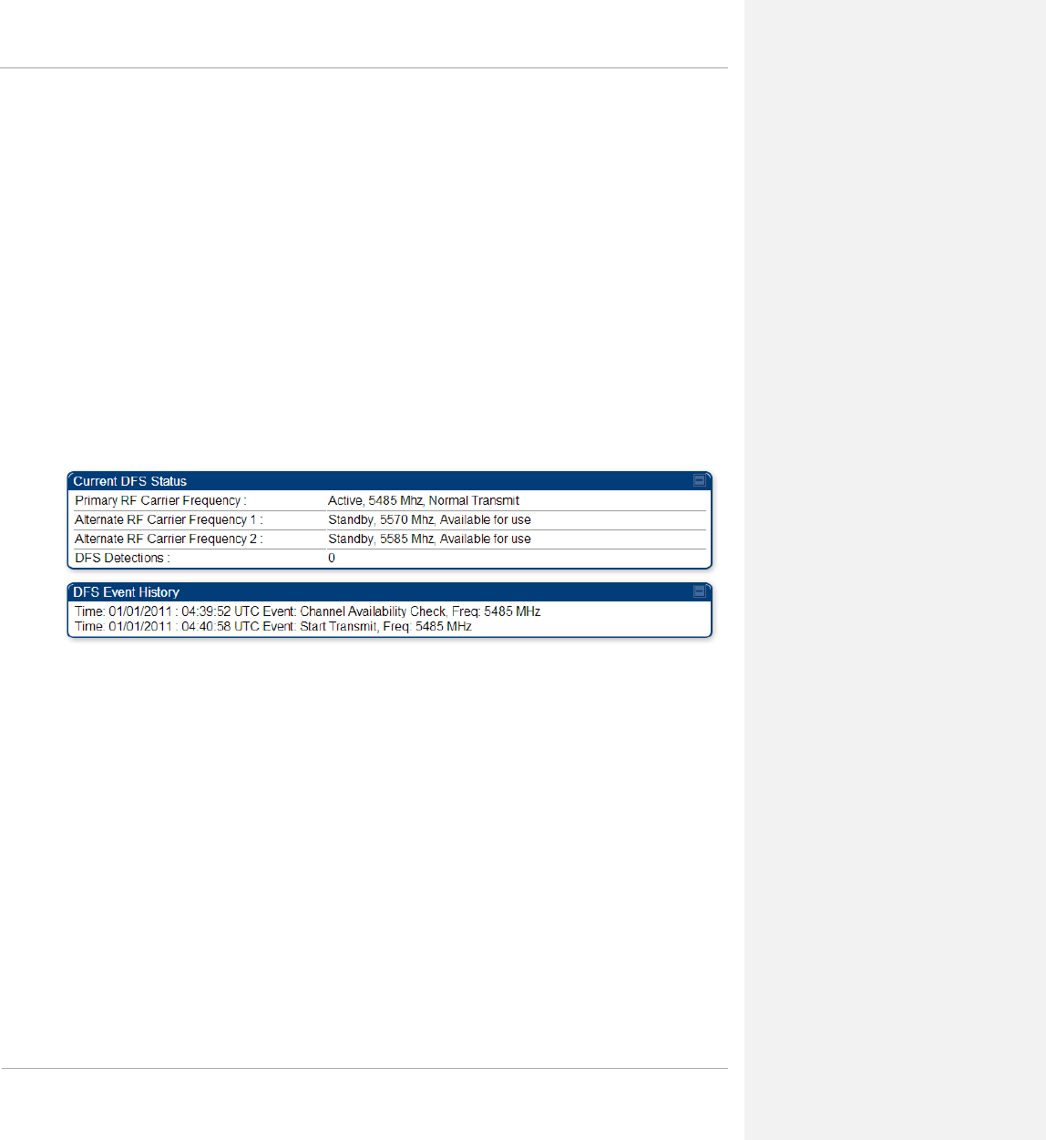
PMP 450 Planning Guide Glossary
DFS for 5.4 GHz Radios
Dynamic Frequency Selection (DFS) is a requirement in several countries and regions for 5 GHz unlicensed
systems to detect radar systems and avoid co-channel operation. DFS and other regulatory requirements drive the
settings for the following parameters, as discussed in this section:
• Country Code
• Primary Frequency
• Alternate 1 and Alternate 2 Frequencies
• External Antenna Gain
On the AP, the Home => DFS Status” page shows current DFS status of all three frequencies and a DFS log of past
DFS events.
Figure 33 AP DFS Status
Background and Operation
The modules use region-specific DFS based on the Country Code selected on the module’s Configuration, General
page. By directing installers and technicians to set the Country Code correctly, the operator gains confidence the
module is operating according to national or regional regulations without having to deal with the details for each
region.
Some regions have requirements to avoid certain 5.4-GHz frequencies used by some weather radar. To meet this
requirement, modules set to Europe will display the certain channel frequencies shown in page 3-21 on the AP’s
Carrier Frequency pop-up and on the SM’s Frequency Scan Selection List.
Table 70 on page 3-19 shows the details of DFS operation and channels available for each Country Code, including
whether DFS is active on the AP, SM, which DFS regulation apply, and any channel restrictions. DFS does not
apply to 4.9 GHz.
3-18 pmp-0047 (March 2014)

PMP 450 Planning Guide Glossary
Table 70 OFDM DFS operation based on Country Code setting
Region
Code Country
Code Band AP SM Weather
Radar
Notch-
Out
Asia
Vietnam 5.4-GHz ETSI EN 301 893
v1.6.1 DFS
ETSI EN 301 893
v1.6.1 DFS
No
India,
Vietnam,
Indonesia
5.8-GHz No effect No effect
Oceania Australia 5.4-GHz FCC DFS No effect Yes
5.8-GHz No effect No effect No
Europe
Denmark,
Finland,
Germany,
Greece,
Iceland,
Ireland,
Liechtenstein,
Norway,
Portugal,
Serbia, Spain,
Switzerland,
United
Kingdom
5.4-GHz ETSI EN 301 893
v1.6.1 DFS
ETSI EN 301 893
v1.6.1 DFS Yes
5.8-GHz ETSI EN 302 502
v1.2.1 DFS
ETSI EN 302 502
v1.2.1 DFS No
South
America Brazil 5.4-GHz ETSI EN 301 893
v1.6.1 DFS No effect No
5.8-GHz No effect No effect No
North
America
Canada
2.4-GHz No effect No effect No
5.4-GHz FCC/IC DFS No effect Yes
5.8-GHz No effect No effect No
United States
2.4GHz No effect No effect No
5.4-GHz FCC DFS No effect Yes
5.8-GHz No effect No effect No
Other-Other-FCC 2.4-GHz No effect No effect No
pmp-0047 (March 2014) 3-19

PMP 450 Planning Guide Glossary
Region
Code Country
Code Band AP SM Weather
Radar
Notch-
Out
Regulatory
5.4-GHz FCC DFS FCC DFS
5.8-GHz No effect No effect
Other-ETSI
5.4-GHz ETSI EN 301 893
v1.6.1 DFS
ETSI EN 301 893
v1.6.1 DFS No
5.8-GHz ETSI EN 302 502
v1.2.1 DFS
ETSI EN 302 502
v1.2.1 DFS No
Country Codes and available spectrum
The following tables list the Country Codes available on PMP 450 AP and SM units. Country Code settings affect
the radios in the following ways:
• Maximum transmit power limiting (based on radio transmitter power plus configured antenna gain)
• DFS operation is enabled based on the configured region code, if applicable
PMP 450 equipment shipped to the United States is locked to a Country Code setting of “United States”. Units
shipped to regions other than the United States must be configured with the corresponding Country Code to comply
with local regulatory requirements.
3-20 pmp-0047 (March 2014)
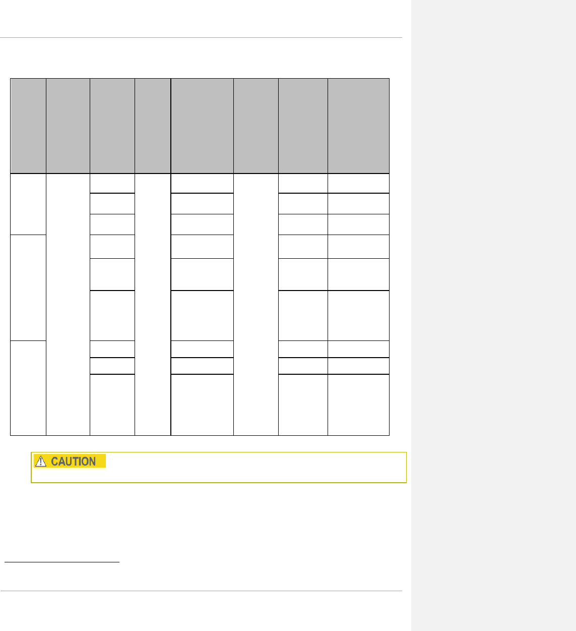
PMP 450 Planning Guide Glossary
Table 71 Center channel details based on Country Code, 2.4 GHz
OFDM
Radio
Model Country Channel
Size
Band
Edges
(MHz)
Range of
Center
Frequencies
Available
(MHz)‡‡‡‡‡‡
Center
Channel
Spacing
# of
Center
Channels
(based
on PMP
450
available
range)
# of Non-
overlapping
center
channels
(based on
PMP 450
available
range)
PMP
450
Series
AP, 2.4-
GHz
United
States,
Canada,
Other-
FCC
5 MHz
2400-
2483.5
2402.5 – 2475
2.5 MHz
30 15
10 MHz 2405 – 2470 27 7
20 MHz 2417.5– 2460 18 3
PMP
450
Series
SM,
2.4-
GHz,
internal
Patch
Antenna
5 MHz 2402.5 – 2475 30 15
10 MHz 2405 – 2470 27 7
20 MHz 2417.5– 2460 18
3
PMP
450
Series
SM,
2.4-
GHz,
Dish
Antenna
5 MHz 2407.5 – 2465 24 12
10 MHz 2420 – 2450 13 4
20 MHz 2430 – 2445 7
1
For each edge frequency, transmit power must be reduced by 3 dB.
‡‡‡‡‡‡ For each edge frequency, transmit power must be reduced by 3 dB.
pmp-0047 (March 2014) 3-21

PMP 450 Planning Guide Glossary
Table 72 AP Default combined transmits power per Country Code and Lower/Upper Band Edge
Path Max TX Detail, 2.4 GHz.
Country Ant.
Gain
(dBi)
(18 dBi
– 1dB
cable
loss)
Comb. TX
Default
Setting
AP
EIRP
Limit
Comb. TX
Default
Setting
AP
EIRP
Limit
Comb.
TX
Default
Setting
AP
EIRP
Limit
Device
Country
Code
Setting
5 MHz Channel
Bandwidth (dBm) 10 MHz Channel
Bandwidth (dBm) 20 MHz Channel
Bandwidth
(dBm)
Canada 17 19 36 19 36 19 36 Canada
United States 17 19 36 19 36 19 36 United States
Lower Band Edge Frequency
(MHz)
Path A Max TX
Power Path B Max TX
Power
AP
5 MHz
240
2.5 16 16
10 MHz
2405
15 14
20 MHz
2417.5
15 15
SM
5 MHz
2402.5
15 15
10 MHz
2405
15 15
20 MHz
2417.5
18 18
Upper Band Edge Frequency
(MHz)
Path A Max TX
Power Path B Max TX
Power
AP
5 MHz
2475
16 16
10 MHz
2470
15 14
20 MHz
2460
15 15
SM
5 MHz
2475
15 15
10 MHz
2470
15 15
20 MHz
2460
18 18
3-22 pmp-0047 (March 2014)

PMP 450 Planning Guide Glossary
Table 73 Center channel details based on Country Code, 3.5 GHz
Region Code
Channel
Size
Band Edges
(MHz)
Range of
Center
Frequencies
Available (MHz)
Center
Channel
Spacing
# of Center
Channels
(based on PMP
450 available
range)
# of Non-
overlapping
center channels
(based on PMP
450 available
range)
Level 1
Level 2
Other
Other-ETSI
(Any country
that follows
ETSI rules)
5 MHz
3400 – 3600
3402.5 – 3597.5
50 kHz
3900 39
10 MHz 3405 - 3595 3800 19
20 MHz 3410 - 3590 3600 9
Asia
India
5 MHz
3300 – 3600
3302.5 – 3597.5
50 kHz
5900 59
10 MHz 3305 - 3595 5800 29
20 MHz 3310 - 3590 5600 14
Indonesia
5 MHz
3300 – 3400
3302.5 – 3397.5
50 kHz
1900 19
10 MHz 3305 - 3395 1800 9
20 MHz 3310 - 3390 1600 4
China
5 MHz
3300 – 3400
3302.5 – 3397.5
50 kHz
1900 19
10 MHz 3305 - 3395 1800 9
20 MHz 3310 - 3390 1600 4
Oceania Australia
5 MHz
3300 – 3600
3302.5 – 3597.5
50 kHz
5900 59
10 MHz 3305 - 3595 5800 29
20 MHz 3310 - 3590 5600 14
North
America
Canada
5 MHz 3450 -3650§§§§§§
(3475-3650
for new
deployments)
3452.5 – 3647.5
50 kHz
3900 39
10 MHz 3455 – 3645 3800 19
20 MHz 3460 – 3640 3600 9
Mexico
5 MHz
3300 – 3600
3302.5 – 3597.5
50 kHz
5900 59
10 MHz 3305 - 3595 5800 29
20 MHz 3310 - 3590 5600 14
Europe
Europe
(Denmark,
Finland,
5 MHz
3400 - 3600
3402.5 – 3597.5
50 kHz
3900 39
10 MHz 3405 - 3595 3800 19
§§§§§§ System Release 13.0 allows an upper limit of 3600MHz. Range may be extended in a future release.
pmp-0047 (March 2014) 3-23
PMP 450 Planning Guide Glossary
Region Code
Channel
Size
Band Edges
(MHz)
Range of
Center
Frequencies
Available (MHz)
Center
Channel
Spacing
# of Center
Channels
(based on PMP
450 available
range)
# of Non-
overlapping
center channels
(based on PMP
450 available
range)
Level 1
Level 2
France,
Germany,
Greece,
Iceland,
Ireland, Italy,
Liechtenstein,
Norway,
Portugal,
Serbia, Spain,
Switzerland,
United
Kingdom)
20 MHz 3410 - 3590 3600 9
3-24 pmp-0047 (March 2014)

PMP 450 Planning Guide Glossary
Table 74 AP default combined transmit power per Country Code – 3.5 GHz band.
Country Antenna
Gain (dBi)
Combined
TX
Default
AP EIRP
Limit
Combined
TX
Default
AP EIRP
Limit
Combined
TX
Default
AP EIRP
Limit
Device Country
Code Setting
(Level 2)
5 MHz Channel
Bandwidth (dBm)
10 MHz Channel
Bandwidth (dBm)
20 MHz Channel
Bandwidth (dBm)
Australia 17 23 57 23 60 23 63 Australia
Canada 17 23 62 23 62 23 62 Canada
China 17 23 N/A 23 N/A 23 N/A China
Denmark 17 23 60 23 63 23 66 Denmark
Finland 17 23 60 23 63 23 66 Finland
France 17 23 60 23 63 23 66 France
Germany 17 23 60 23 63 23 66 Germany
Greece 17 23 60 23 63 23 66 Greece
India 17 23 N/A 23 N/A 23 N/A India
Iceland 17 23 60 23 63 23 66 Iceland
Indonesia 17 23 N/A 23 N/A 23 N/A Indonesia
Ireland 17 23 60 23 63 23 66 Ireland
Italy 17 23 60 23 63 23 66 Italy
Liechtenstein 17 23 60 23 63 23 66 Liechtenstein
Mexico 17 23 N/A 23 N/A 23 N/A Mexico
Norway 17 23 60 23 63 23 66 Norway
Portugal 17 23 60 23 63 23 66 Portugal
Serbia 17 23 60 23 63 23 66 Serbia
Spain 17 23 60 23 63 23 66 Spain
Switzerland 17 23 60 23 63 23 66 Switzerland
United Kingdom 17 23 60 23 63 23 66 United Kingdom
pmp-0047 (March 2014) 3-25

PMP 450 Planning Guide Glossary
Table 75 Center channel details based on Country Code, 3.6 GHz
Region Code
Channel
Size
Band Edges
(MHz)
Range of Center
Frequencies
Available (MHz)
Center
Channel
Spacing
# of Center
Channels (based
on PMP 450
available range)
# of Non-
overlapping center
channels (based on
PMP 450 available
range)
Level 1
Level 2
Other
Other
5 MHz
3550 – 3800
3552.5 – 3797.5
50 kHz
4900 48
10 MHz 3555 – 3795 4800 23
20 MHz 3560 – 3790 4600 10.5
Other - ETSI
(Any country
that follows ETSI
rules)
5 MHz
3550 – 3800
3552.5 – 3797.5
50 kHz
4900 48
10 MHz 3555 – 3795 4800 23
20 MHz 3560 – 3790 4600 10.5
Other – FCC
5 MHz
3650 – 3700
3652.5 – 3697.5
50 kHz
2900 28
10 MHz 3655 – 3695 2800 13
20 MHz 3660 – 3690 2600 5.5
Asia
India
5 MHz
3550 – 3800
3552.5 – 3797.5
50 kHz
4900 48
10 MHz 3555 – 3795 4800 23
20 MHz 3560 – 3790 4600 10.5
Indonesia
5 MHz
3600 – 3800
3602.5 – 3797.5
50 kHz
3900 38
10 MHz 3605 – 3795 3800 18
20 MHz 3610 – 3790 3600 8
Oceania Australia
5 MHz
3550 – 3800
3552.5 – 3797.5
50 kHz
4900 48
10 MHz 3555 – 3795 4800 23
20 MHz 3560 – 3790 4600 10.5
North
America
Canada
5 MHz
3550 – 3700
3552.5 – 3697.5
50 kHz
2900 28
10 MHz 3555 – 3695 2800 13
20 MHz 3560 – 3690 2600 5.5
Mexico
5 MHz
3550 – 3750
3552.5 – 3747.5
50 kHz
3900 38
10 MHz 3555 – 3745 3800 18
20 MHz 3560 – 3740 3600 8
United States
5 MHz
3650 – 3700
3652.5 – 3697.5
50 kHz
900 8
10 MHz 3655 – 3695 800 3
3-26 pmp-0047 (March 2014)
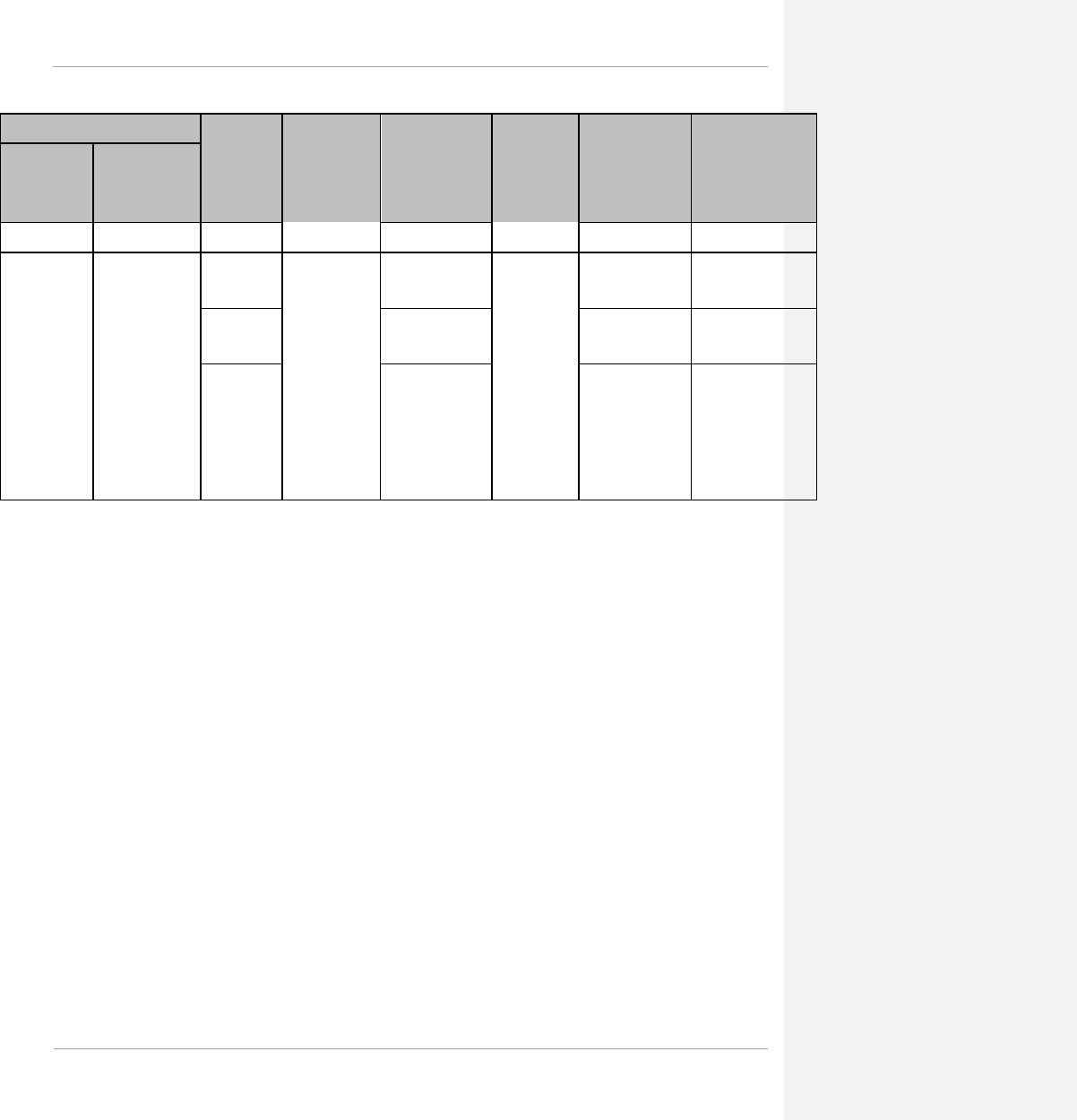
PMP 450 Planning Guide Glossary
Region Code
Channel
Size
Band Edges
(MHz)
Range of Center
Frequencies
Available (MHz)
Center
Channel
Spacing
# of Center
Channels (based
on PMP 450
available range)
# of Non-
overlapping center
channels (based on
PMP 450 available
range)
Level 1
Level 2
20 MHz 3660 – 3690 600 0.5
Europe
Europe
(Denmark,
Finland, France,
Germany,
Greece, Iceland,
Ireland, Italy,
Liechtenstein,
Norway,
Portugal, Serbia,
Spain,
Switzerland,
United Kingdom)
5 MHz
3550 – 3800
3552.5 – 3797.5
50 kHz
4900 48
10 MHz 3555 – 3795 4800 23
20 MHz 3560 – 3790 4600 10.5
pmp-0047 (March 2014) 3-27

PMP 450 Planning Guide Glossary
Table 76 AP default combined transmit power per Country Code – 3.6 GHz band
Country Antenna
Gain (dBi)
Combined
TX
Default
AP EIRP
Limit
Combined
TX
Default
AP EIRP
Limit
Combined
TX
Default
AP EIRP
Limit
Device Country
Code Setting
(Level 2)
5 MHz Channel
Bandwidth (dBm)
10 MHz Channel
Bandwidth (dBm)
20 MHz Channel
Bandwidth (dBm)
Australia 17 25 N/A 25 N/A 25 N/A Australia
Canada
(3550 – 3650) 17 25 62 25 62 25 62 Canada
Canada
(3650 – 3700) 17 19 37 22 40 25 43 Canada
Denmark 17 25 60 25 63 25 66 Denmark
Finland 17 25 60 25 63 25 66 Finland
France 17 25 60 25 63 25 66 France
Germany 17 25 60 25 63 25 66 Germany
Greece 17 25 60 25 63 25 66 Greece
India 17 25 N/A 25 N/A 25 N/A India
Indonesia 17 25 N/A 25 N/A 25 N/A Indonesia
Ireland 17 25 60 25 63 25 66 Ireland
Italy 17 25 60 25 63 25 66 Italy
Liechtenstein 17 25 60 25 63 25 66 Liechtenstein
Mexico 17 25 N/A 25 N/A 25 N/A Mexico
Norway 17 25 60 25 63 25 66 Norway
Portugal 17 25 60 25 63 25 66 Portugal
Serbia 17 25 60 25 63 25 66 Serbia
Spain 17 25 60 25 63 25 66 Spain
Switzerland 17 25 60 25 63 25 66 Switzerland
United Kingdom 17 25 60 25 63 25 66 United Kingdom
United States 17 19 37 22 40 25 43 United States
3-28 pmp-0047 (March 2014)

PMP 450 Planning Guide Glossary
Table 77 Center channel details based on Country Code, 5.4 GHz
OFDM
Radio
Model
Country
Code Channel
Size Band
Edges
(MHz)
Range of
Center
Frequencies
Available
(MHz)
Center
Channel
Spacing
# of
Center
Channels
(based on
PMP 450
available
range,
weather
notch-out)
# of Non-
overlapping
center
channels
(based on
PMP 450
available
range)
PMP 450
Series
AP, 5.4-
GHz
Brazil 10 MHz 5470 –
5725
5475 – 5720
2.5 MHz
99 25
20 MHz 5480 – 5715 95 12
Australia,
Denmark,
Finland,
Germany,
Greece,
Iceland,
Ireland,
Liechtenstein,
Norway,
Portugal,
Serbia, Spain,
Switzerland,
United
Kingdom
10 MHz
5470 –
5600;
5650 -
5725
5475 – 5595;
5655 -
5720*******
77 20
20 MHz
5480 – 5590;
5660 –
5710*******
67 9
United States,
Canada
10 MHz 5470 –
5600;
5650 –
5725
5475 – 5595;
5655 - 5720 77 20
20 MHz 5480 – 5590;
5660 – 5715 69 9
Other 10 MHz 5470 –
5725
5475 - 5720 99 25
20 MHz 5480 – 5715 95 12
******* Frequencies 5600 – 5650 MHz are excluded, as ten minute Channel Availability Check is required
pmp-0047 (March 2014) 3-29

PMP 450 Planning Guide Glossary
Table 78 Center channel details based on Country Code, 5.8 GHz
OFDM
Radio
Model
Country Channel
Size Band
Edges
(MHz)
Range of
Center
Frequencies
Available
(MHz)
Center
Channel
Spacing
# of
Center
Channels
(based on
PMP 450
available
range,
weather
notch-out)
# of Non-
overlapping
center
channels
(based on
PMP 450
available
range)
PMP 450
Series AP,
5.8-GHz
Denmark,
Norway, United
Kingdom,
Finland
10 MHz 5725 – 5795;
5815 – 5850
5730 – 5790;
5820 – 5845
2.5 MHz
37 10
20 MHz 5735 – 5785;
5825 – 5840 29 4
Germany 10 MHz 5755 – 5875; 5760 – 5870 45 12
20 MHz 5765 – 5865 41 6
Spain
10 MHz 5725 – 5795;
5815 – 5855
5730- 5790;
5820 – 5850 39 10
20 MHz 5735 – 5785;
5825 – 5845 31 4
Greece 10 MHz 5725 – 5795 5730 – 5790 25 7
20 MHz 5735 – 5785 21 3
Portugal,
Iceland, Serbia
10 MHz 5725 – 5875 5730 – 5870 57 15
20 MHz 5735 – 5865 53 7
Switzerland,
Liechtenstein
10 MHz 5725 – 5795;
5815 – 5875
5730 – 5790;
5820 – 5870 47 12
20 MHz 5735 – 5785;
5825 – 5865 39 5
Australia
5 MHz
5725 - 5850
5727.5 – 5847.5 49 25
10 MHz 5730 – 5845 47 12
20 MHz 5735 – 5840 43 6
Canada, United
States
5 MHz
5725 - 5850
5730 - 5845 47 24
10 MHz 5730 – 5845 12
20 MHz 5735 – 5845 45 6
India 5 MHz 5825 – 5875 5827.5 – 5872.5 19 10
3-30 pmp-0047 (March 2014)
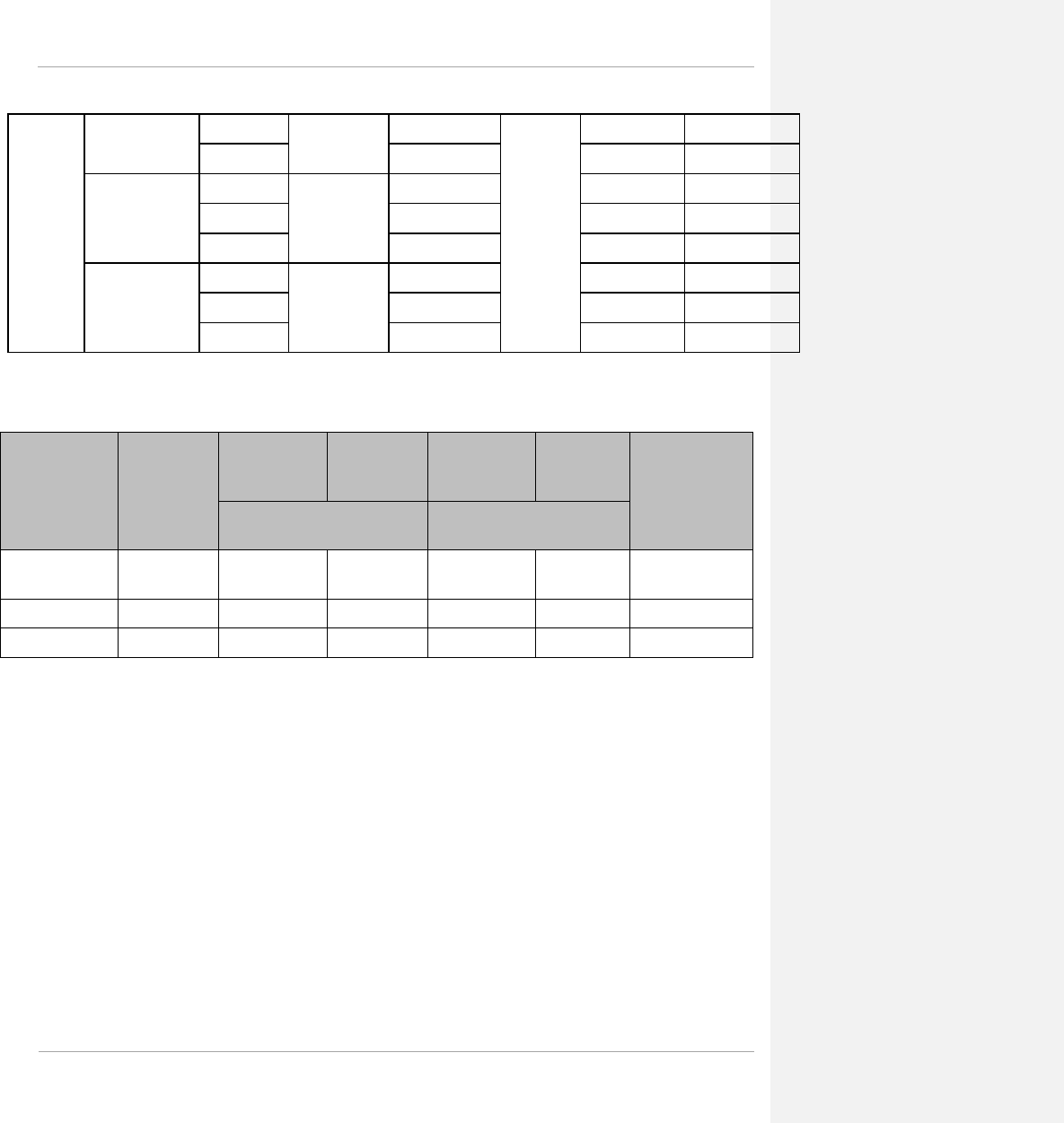
PMP 450 Planning Guide Glossary
10 MHz 5830 - 5870 17 5
20 MHz 5835 - 5865 13 2
Brazil, Vietnam
5 MHz
5725 – 5850
5727.5 – 5847.5 49 25
10 MHz 5730 – 5845 47 12
20 MHz 5735 - 5840 43 6
Indonesia
5 MHz
5725 - 5825
5727.5 – 5822.5 39 20
10 MHz 5730 – 5820 37 10
20 MHz 5735 - 5815 33 5
Table 79 Default combined transmit power per Country Code – 5.4 GHz band
Country
Antenna
Gain (dBi)
(18 dBi –
1dB cable
loss)
Combined
TX Default
Setting
AP EIRP
Limit
Combined
TX Default
Setting
AP EIRP
Limit Device
Country Code
Setting
10 MHz Channel
Bandwidth (dBm) 20 MHz Channel
Bandwidth (dBm)
United States,
Canada 17 10 27 13 30 United States,
Canada
Brazil 17 10 27 13 30 Brazil
Algeria 17 13 30 13 30 Algeria
pmp-0047 (March 2014) 3-31

PMP 450 Planning Guide Glossary
Country
Antenna
Gain (dBi)
(18 dBi –
1dB cable
loss)
Combined
TX Default
Setting
AP EIRP
Limit
Combined
TX Default
Setting
AP EIRP
Limit Device
Country Code
Setting
10 MHz Channel
Bandwidth (dBm) 20 MHz Channel
Bandwidth (dBm)
Australia 17 10 27 13 30 Australia
3-32 pmp-0047 (March 2014)

PMP 450 Planning Guide Glossary
Country
Antenna
Gain (dBi)
(18 dBi –
1dB cable
loss)
Combined
TX Default
Setting
AP EIRP
Limit
Combined
TX Default
Setting
AP EIRP
Limit Device
Country Code
Setting
10 MHz Channel
Bandwidth (dBm) 20 MHz Channel
Bandwidth (dBm)
Austria, Belgium,
Bosnia &
Herzegovina,
Bulgaria, Croatia,
Cyprus, Czech
Republic, France,
, Hungary,
Ireland, Italy,
Latvia, Lithuania,
Luxembourg,
Macedonia,
Malta,
Netherlands,
Poland, Romania,
Slovakia,
Slovenia ,
Sweden
17 10 27††††††† 13 30 Other-ETSI
Denmark 17 10 27 13 30 Denmark
Finland 17 10 27 13 30 Finland
Germany 17 10 27 13 30 Germany
Greece 17 10 27 13 30 Greece
Liechtenstein 17 10 27 13 30 Liechtenstein
Norway 17 10 27 13 30 Norway
Portugal 17 10 27 13 30 Portugal
Spain 17 10 27 13 30 Spain
United Kingdom 17 10 27 13 30 United Kingdom
Vietnam 17 10 27 13 30 Vietnam
Other 17 19 No EIRP /
Conducted
power limit
19
No EIRP /
Conducted
power limit
Other
††††††† At 5.4 GHz, EU regulations are harmonized. 5600 – 5650 MHz excluded, as ten minute Channel Availability Check
(CAC) is required
pmp-0047 (March 2014) 3-33

PMP 450 Planning Guide Glossary
Table 80 Default combined transmit power per Country Code – 5.8 GHz band
Country
Code Antenna
Gain
(dBi)
(18 dBi –
1dB cable
loss)
Combined
TX
Default
AP EIRP
Limit
Combined
TX
Default
Setting
AP EIRP
Limit
Combined
TX
Default
Setting
AP EIRP
Limit
Device
Country
Code
Setting
5 MHz Channel
Bandwidth
(dBm)
10 MHz Channel
Bandwidth (dBm) 20 MHz Channel
Bandwidth (dBm)
Australia 17 19 36 19 36 19 36 Australia
Brazil 17 7 24 10 27 13 30 Brazil
Canada 17 9 26 19 36 19 36 Canada
Denmark 17 16 33 19 36 Denmark
Finland 17 16 33 19 36 Finland
Germany 17 16 33 19 36 Germany
Greece 17 16 33 19 36 Greece
India 17 19 36 19 36 19 36 India
Iceland 17 16 33 19 36 Iceland
Indonesia 17 13 30 19 36 19 36 Indonesia
Ireland 17 13 30 16 33 Ireland
Liechtenstein 17 16 33 19 36 Liechtenstein
Norway 17 16 33 19 36 Norway
Portugal 17 16 33 19 36 Portugal
Serbia 17 16 33 19 36 Serbia
Spain 17 16 33 19 36 Spain
Switzerland 17 16 33 19 36 Switzerland
United
Kingdom 17 16 33 19 36 United
Kingdom
United States 17 19 36 19 36 19 36 United States
Vietnam 17 7 24 10 27 13 30 Vietnam
3-34 pmp-0047 (March 2014)

PMP 450 Planning Guide Glossary
After an AP with DFS is powered on it performs a channel availability check on its main carrier frequency for 1
minute, monitoring for the radar signature without transmitting. If no radar signature is detected during this minute,
the module then proceeds to normal beacon transmit mode. If it does detect a radar signature, the frequency is
marked for a 30 minute non-occupancy period, and the module moves to its 1st alternate carrier frequency. The AP
continues this behavior through its 2nd alternate frequency if needed and then waits until the first frequency ends
the 30 minute non-occupancy period. While operating, if the AP detects a weather radar signature it marks the
current carrier frequency for a 30 minute non-occupancy period and moves to check the next-in-line carrier
frequency.
An SM does not begin transmission until it detects a beacon from an AP. If APs are not transmitting, SMs will be
silent.
Europe applies the ETSI specification to both APs and SMs, while Brazil applies it only to APs. In the ETSI case,
when an SM is powered on, it scans to find a Canopy beacon from a AP. If an AP is found, the SM performs a
channel availability check on that frequency for 1 minute, monitoring for the radar signature, without transmitting.
A DFS decision is made based on the following:
• If no radar pulse is detected during this 1 minute, the SM proceeds through normal steps to register to an AP.
• If the SM does detect radar, it locks out that frequency for 30 minutes and continues scanning other frequencies
in its scan list.
After an SM with DFS has seen a radar signature on a frequency and locked out that frequency, it may connect to a
different AP if color codes, AP transmitting frequencies, and SM scanned frequencies support that connection.
To simplify operation and ensure compliance, an SM takes on the DFS type of the AP to which it registers. For
example, when an SM in Europe registers to an AP with the Country Code set to “United Kingdom”, that SM will
use ETSI DFS, no matter what its Country Code is set to, even if its Country Code is set to “None”. Note, the
operator should still configure the Country Code in the SM correctly, as future releases may use the Country Code
for additional region-specific options.
For all modules running DFS, the module displays its DFS state on its Home => General Status page as one of the
following:
• Checking Channel Availability Remaining time n seconds, where n counts down from 60 to
1.
• Normal Transmit
• Radar Detected Stop Transmitting for n minutes, where n counts down from 30 to 1.
• Idle, only for SM/BHS, indicates module is scanning, but has not detected a beacon from an AP/BHM. Once it detects
beacon, the SM/BHS begins a Channel Availability Check on that frequency.
pmp-0047 (March 2014) 3-35
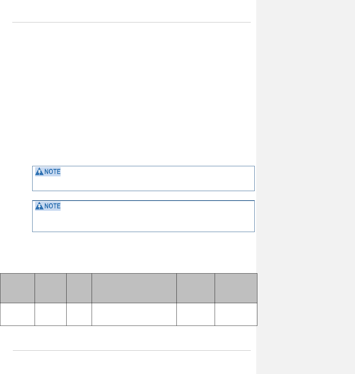
PMP 450 Planning Guide Glossary
Regulatory Note: A PMP 450 Series AP with a Country Code set to United States will not be configurable to
another Country Code by installers or end users. This is in response to FCC KDB 594280 and ensures that end users
and professional installers will not have access to settings which could allow a radio to be configured to operate in a
manner other than that which was specified in the FCC equipment authorization grant.
Within the United States and its territories the PMP 450 Country Code is pre-configured to United States and not
selectable in the Configuration, General web page. Radios sold in regions outside of the United States and its
territories are required to set the Country Code to the region in which it is used.
FCC compliance testing
With GPS synchronization installed, the system has been tested for compliance to US (FCC) specifications. It has
been shown to comply with the limits for emitted spurious radiation for a Class B digital device, pursuant to Part 15
of the FCC Rules in the USA. These limits have been designed to provide reasonable protection against harmful
interference. However the equipment can radiate radio frequency energy and, if not installed and used in accordance
with the instructions, may cause harmful interference to other radio communications. There is no guarantee that
interference will not occur in a particular installation.
A Class B Digital Device is a device that is marketed for use in a residential environment, notwithstanding use in
commercial, business and industrial environments.
Notwithstanding that Cambium has designed (and qualified) the PMP 450 products to generally meet the Class B
requirement to minimize the potential for interference, the PMP 450 product range is not marketed for use in a
residential environment.
FCC and ICC IDs and certification numbers
Table 81 US FCC IDs and Industry Canada Certification Numbers and Covered Configurations
FCC ID Industry
Canada
Cert
Number
Module
Families
Frequencies Antenna
(OFDM) Maximum
Combined
Tx Output
Power
Z8H89FT0004 109W-0004
PMP 450 AP
2.4-GHz
20 MHz channels, centered on 2417.5 –
2460 in 2.5 MHz increments (within the
2400 – 2483.5 MHz ISM band)
17 dBi
Connectorized 19 dBm
3-36 pmp-0047 (March 2014)

PMP 450 Planning Guide Glossary
FCC ID Industry
Canada
Cert
Number
Module
Families
Frequencies Antenna
(OFDM) Maximum
Combined
Tx Output
Power
10 MHz channels, centered on 2405 –
2470 in 2.5 MHz increments (within the
2400 – 2483.5 MHz ISM band)
5 MHz channels, centered on 2402.5 –
2475 in 2.5 MHz increments (within the
2400 – 2483.5 MHz ISM band)
109W-0008
PMP 450 AP
3.5-GHz
20 MHz channels, centered on 3460 –
3640 in 50 kHz increments (within the
3300 – 3600 MHz ISM band)
17 dBi
Connectorized 25 dBm
10 MHz channels, centered on 3455 –
3645 in 50 kHz increments (within the
3300 – 3600 MHz ISM band)
5 MHz channels, centered on 3452.5 -
3647.5 in 50 kHz increments (within the
3300 – 3600 MHz ISM band)
Z8H89FT0010 109W-0010
PMP 450 AP
3.6-GHz
20 MHz channels, centered on 3660 –
3690 in 50 kHz increments (within the
3550 – 3800 MHz ISM band)
17 dBi
Connectorized
25 dBm
10 MHz channels, centered on 3655 –
3695 in 50 kHz increments (within the
3550 – 3800 MHz ISM band)
22 dBm
pmp-0047 (March 2014) 3-37

PMP 450 Planning Guide Glossary
FCC ID Industry
Canada
Cert
Number
Module
Families
Frequencies Antenna
(OFDM) Maximum
Combined
Tx Output
Power
5 MHz channels, centered on 3652.5 -
3697.5 in 50 kHz increments (within the
3550 – 3800 MHz ISM band)
19 dBm
Z8H89FT0002 109W-0002
PMP 450 AP
5.8-GHz
20 MHz channels, centered on 5735-5840
in 2.5 MHz increments (within the 5725-
5850 MHz ISM band)
17 dBi
Connectorized 19 dBm
10 MHz channels, centered on 5730-5845
in 2.5 MHz increments (within the 5725-
5850 MHz ISM band)
5 MHz channels, centered on 5725-5850
in 2.5 MHz increments (within the 5725-
5850 MHz ISM band)
Z8H89FT0002 109W-0002
PMP 450 AP
5.4-GHz
20 MHz channels, centered on 5480 –
5590; 5660 – 5715 in 2.5 MHz
increments (within the 5470 – 5600; 5650
– 5725 MHz UNII band)
17 dBi
Connectorized
13 dBm
10 MHz channels, centered on 5475 –
5595; 5655 – 5720 in 2.5 MHz
increments (within the 5470 – 5600; 5650
– 5725 MHz UNII band)
10 dBm
Z8H89FT0003 109W-0003 PMP 450
SM 2.4-GHz
20 MHz channels, centered on 2417.5 –
2460 in 2.5 MHz increments (within the
2400 – 2483.5 MHz ISM band)
7 dBi Integrated 19 dBm
7 dBi Integrated
with 12 dBi
Reflector Dish
17 dBm
10 MHz channels, centered on 2405 –
2470 in 2.5 MHz increments (within the
2400 – 2483.5 MHz ISM band)
7 dBi Integrated 19 dBm
7 dBi Integrated
with 12 dBi
Reflector Dish
17 dBm
3-38 pmp-0047 (March 2014)

PMP 450 Planning Guide Glossary
FCC ID Industry
Canada
Cert
Number
Module
Families
Frequencies Antenna
(OFDM) Maximum
Combined
Tx Output
Power
5 MHz channels, centered on 2402.5 –
2475 in 2.5 MHz increments (within the
2400 – 2483.5 MHz ISM band)
7 dBi Integrated 19 dBm
7 dBi Integrated
with 12 dBi
Reflector Dish
17 dBm
109W-0007 PMP 450
SM 3.5-
GHz
20 MHz channels, centered on 3460 –
3640 in 50 kHz increments (within the
3300 – 3600 MHz ISM band)
8 dBi Integrated 25 dBm
8 dBi Integrated
with 11 dBi
Reflector Dish
25 dBm
10 MHz channels, centered on 3455 –
3645 in 50 kHz increments (within the
3300 – 3600 MHz ISM band)
8 dBi Integrated 25 dBm
8 dBi Integrated
with 11 dBi
Reflector Dish
25 dBm
5 MHz channels, centered on 3452.5 -
3647.5 in 50 kHz increments (within the
3300 – 3600 MHz ISM band)
8 dBi Integrated 25 dBm
8 dBi Integrated
with 11 dBi
Reflector Dish
25 dBm
Z8H89FT0009 109W-0009 PMP 450
SM 3.6-
GHz
20 MHz channels, centered on 3560 –
3690 in 50 kHz increments (within the
3550 – 3800 MHz ISM band)
8 dBi Integrated 25 dBm
8 dBi Integrated
with 11 dBi
Reflector Dish
25 dBm
Connectorized
with 22 dBi
panel
19 dBm
10 MHz channels, centered on 3555 –
3695 in 50 kHz increments (within the
3550 – 3800 MHz ISM band)
8 dBi Integrated 22 dBm
8 dBi Integrated
with 11 dBi
Reflector Dish
22 dBm
Connectorized
with 22 dBi
panel
19 dBm
5 MHz channels, centered on 3552.5 -8 dBi Integrated 19 dBm
pmp-0047 (March 2014) 3-39

PMP 450 Planning Guide Glossary
FCC ID Industry
Canada
Cert
Number
Module
Families
Frequencies Antenna
(OFDM) Maximum
Combined
Tx Output
Power
3697.5 in 50 kHz increments (within the
3550 – 3800 MHz ISM band)
8 dBi Integrated
with 11 dBi
Reflector Dish
19 dBm
Connectorized
with 22 dBi
panel
19 dBm
Z8H89FT0001 109W-0001 PMP 450
SM 5.8-GHz
20 MHz channels, centered on 5735-5840
in 2.5 MHz increments (within the 5725-
5850 MHz ISM band)
9 dBi Integrated
19 dBm
9 dBi Integrated
with 14 dBi
Reflector Dish
9 dBi Integrated
with 5.5 dBi
LENS
9 dBi Integrated
with 8 dBi CLIP
10 MHz channels, centered on 5730-5845
in 2.5 MHz increments (within the 5725-
5850 MHz ISM band)
9 dBi Integrated
19 dBm
9 dBi Integrated
with 14 dBi
Reflector Dish
9 dBi Integrated
with 5.5 dBi
LENS
9 dBi Integrated
with 8 dBi CLIP
5 MHz channels, centered on 5725-5845
in 2.5 MHz increments (within the 5725-
5850 MHz ISM band)
9 dBi Integrated
19 dBm
9 dBi Integrated
with 14 dBi
Reflector Dish
9 dBi Integrated
with 5.5 dBi
LENS
9 dBi Integrated
with 8 dBi CLIP
3-40 pmp-0047 (March 2014)

PMP 450 Planning Guide Glossary
FCC ID Industry
Canada
Cert
Number
Module
Families
Frequencies Antenna
(OFDM) Maximum
Combined
Tx Output
Power
Z8H89FT0001 109W-0001 PMP 450
SM 5.4-
GHz
20 MHz channels, centered on 5480 –
5590; 5660 – 5715 in 2.5 MHz
increments (within the 5470 – 5600; 5650
– 5725 MHz UNII band)
9 dBi Integrated 11 dBm
9 dBi Integrated
with 14 dBi
Reflector Dish
7 dBm
9 dBi Integrated
with 5.5 dBi LENS
15 dBm
9 dBi Integrated
with 8 dBi CLIP 13 dBm
10 MHz channels, centered on 5475 –
5595; 5655 – 5720 in 2.5 MHz
increments (within the 5470 – 5600; 5650
– 5725 MHz UNII band)
9 dBi Integrated 10 dBm
9 dBi Integrated
with 14 dBi
Reflector Dish
4 dBm
9 dBi Integrated
with 5.5 dBi LENS
12 dBm
9 dBi Integrated
with 8 dBi CLIP 10 dBm
pmp-0047 (March 2014) 3-41

PMP 450 Planning Guide Glossary
Notifications
This section contains notifications of compliance with the radio regulations that are enforced in various regions.
PMP 450 regulatory compliance
The PMP 450 complies with the regulations that are enforced in the USA and Canada. The relevant notifications are
specified in this section.
PMP 450 FCC and IC notification
U.S. Federal Communication Commission (FCC) and Industry Canada (IC) Notification.
This system has achieved Type Approval in various countries around the world. This means that the system has
been tested against various local technical regulations and found to comply. The frequency band in which the
system operates is ‘license exempt’ and the system is allowed to be used provided it does not cause interference.
The licensing authority does not guarantee protection against interference from other products and installations.
This device complies with part 15 of the US FCC Rules and Regulations and with RSS-210 of Industry Canada.
Operation is subject to the following two conditions: (1) This device may not cause harmful interference, and (2)
This device must accept any interference received, including interference that may cause undesired operation. In
Canada, users should be cautioned to take note that high power radars are allocated as primary users (meaning they
have priority) of the 5650 – 5850 MHz spectrum and these radars could cause interference and/or damage to
license-exempt local area networks (LELAN).
Le présent appareil est conforme aux CNR d'Industrie Canada applicables aux appareils radio exempts de licence.
L'exploitation est autorisée aux deux conditions suivantes : (1) l'appareil ne doit pas produire de brouillage, et (2)
l'utilisateur de l'appareil doit accepter tout brouillage radioélectrique subi, même si le brouillage est susceptible d'en
compromettre le fonctionnement.
Under Industry Canada regulations, this radio transmitter may only operate using an antenna of a type and
maximum (or lesser) gain approved for the transmitter by Industry Canada. To reduce potential radio interference to
other users, the antenna type and its gain should be so chosen that the equivalent isotropically radiated power
(EIRP) is not more than that necessary for successful communication.
Conformément à la réglementation d'Industrie Canada, le présent émetteur radio peut fonctionner avec une antenne
d'un type et d'un gain maximal (ou inférieur) approuvé pour l'émetteur par Industrie Canada. Dans le but de réduire
les risques de brouillage radioélectrique à l'intention des autres utilisateurs, il faut choisir le type d'antenne et son
gain de sorte que la puissance isotrope rayonnée équivalente (PIRE) ne dépasse pas l'intensité nécessaire à
l'établissement d'une communication satisfaisante.
This equipment has been tested and found to comply with the limits for a Class B digital device, pursuant to Part 15
of the US FCC Rules and with RSS-210 of Industry Canada. These limits are designed to provide reasonable
protection against harmful interference in a residential installation. This equipment generates, uses, and can radiate
radio-frequency energy and, if not installed and used in accordance with these instructions, may cause harmful
interference to radio communications. If this equipment does cause harmful interference to radio or television
reception, which can be determined by turning the equipment on and off, the user is encouraged to correct the
interference by one or more of the following measures:
3-42 pmp-0047 (March 2014)

PMP 450 Planning Guide Glossary
• Increase the separation between the affected equipment and the unit;
• Connect the affected equipment to a power outlet on a different circuit from that which the receiver is
connected to;
• Consult the dealer and/or experienced radio/TV technician for help.
Where necessary, the end user is responsible for obtaining any National licenses required to operate this product
and these must be obtained before using the product in any particular country. Contact the appropriate national
administrations for details on the conditions of use for the bands in question and any exceptions that might apply.
This radio transmitter (identify the device by certification number, or model number if Category II) has been
approved by Industry Canada to operate with the antenna types listed below with the maximum permissible gain
and required antenna impedance for each antenna type indicated. Antenna types not included in this list, having a
gain greater than the maximum gain indicated for that type, are strictly prohibited for use with this device.
Le présent émetteur radio (identifier le dispositif par son numéro de certification ou son numéro de modèle s'il fait
partie du matériel de catégorie I) a été approuvé par Industrie Canada pour fonctionner avec les types d'antenne
énumérés ci-dessous et ayant un gain admissible maximal et l'impédance requise pour chaque type d'antenne. Les
types d'antenne non inclus dans cette liste, ou dont le gain est supérieur au gain maximal indiqué, sont strictement
interdits pour l'exploitation de l'émetteur.
Table 82 Industry Canada approved antenna list
Approved Antenna Model Description Input Impedance
C024045D601A 2.4 GHz Dual Slant Antenna for 60
Degree Sector 50 Ω
C030045D901A 3.5 GHz, 3.6 GHz Dual Slant
Antenna for 90 Degree Sector 50 Ω
MA-WA36-DP21N 3.5 GHz, 3.6 GHz Dual Slant
Antenna for 12 Degree Panel 50 Ω
85009324001 5 GHz Dual Slant Antenna for 90
Degree Sector 50 Ω
85009325001 5 GHz Dual Slant Antenna for 60
Degree Sector 50 Ω
Equipment Disposal
Waste (Disposal)
of Electronic
and Electric
Equipment
Please do not dispose of Electronic and Electric Equipment or
Electronic and Electric Accessories with your household waste. In
some countries or regions, collection systems have been set up to
handle waste of electrical and electronic equipment. In European
Union countries, please contact your local equipment supplier
representative or service center for information about the waste
collection system in your country.
pmp-0047 (March 2014) 3-43

PMP 450 Planning Guide Glossary
European Union Notification for 5.4 and 5.8 GHz Product
The 5.4 and 5.8 GHz connectorized product is a two-way radio transceiver suitable for use in Broadband Wireless
Access System (WAS), Radio Local Area Network (RLAN), or Fixed Wireless Access (FWA) systems. It is a
Class 2 device and uses operating frequencies that are not harmonized throughout the EU member states. The
operator is responsible for obtaining any national licenses required to operate this product and these must be
obtained before using the product in any particular country.
Hereby, Cambium declares that the 5.4 and 5.8 GHz product complies with the essential requirements and other
relevant provisions of Directive 1999/5/EC. The relevant Declaration of Conformity can be found at
http://www.cambiumnetworks.com/support/ec-doc.
This equipment is marked to show compliance with the European R&TTE directive
1999/5/EC.
Regulatory Requirements for CEPT Member States (www.cept.org)
When operated in accordance with the instructions for use, Cambium Wireless equipment operating in the 5.4 GHz
bands is compliant with CEPT Recommendation 70-03 Annex 3 for Wideband Data Transmission and
HIPERLANs. For compliant operation in the 5.4 GHz band, the transmit power (EIRP) from the integrated antenna
or a connectorized antenna shall be no more than 0.5 W (27 dBm).
For EU member states, RLAN equipment in the 5.4GHz bands is exempt from individual licensing under
Commission Recommendation 2003/203/EC. Contact the appropriate national administrations for details on the
conditions of use for the bands in question and any exceptions that might apply. Also see www.ero.dk for further
information.
10 MHz channels are used, centered on 5475 to 5595 and 5655 to 5715 in 5 MHz increments. This is within the
5470 to 5725 MHz U-NII band with 5600 to 5650 MHz excluded.
Cambium Radio equipment operating in the 5470 to 5725 MHz band are categorized as “Class 1” devices within
the EU in accordance with ECC DEC(04)08 and are “CE” marked to show compliance with
the European Radio & Telecommunications Terminal Equipment (R&TTE) directive 1999/5/EC. The relevant
Declaration of Conformity can be found at http://www.cambiumnetworks.com/support/ec_doc/.
A European Commission decision, implemented by Member States on 31 October 2005, makes the frequency band
5470-5725 MHz available in all EU Member States for wireless access systems. Under this decision, the
designation of Canopy 5.4GHz products become “Class 1 devices” and these do not require notification under
article 6, section 4 of the R&TTE Directive. Consequently, these 5.4GHz products are only marked with the
symbol and may be used in any member state.
3-44 pmp-0047 (March 2014)

PMP 450 Planning Guide Glossary
UK Notification
The 5.8 GHz connectorized product has been notified for operation in the UK, and when operated in accordance
with instructions for use it is compliant with UK Interface Requirement IR2007. For UK use, installations must
conform to the requirements of IR2007 in terms of EIRP spectral density against elevation profile above the local
horizon in order to protect Fixed Satellite Services. The frequency range 5795-5815 MHz is assigned to Road
Transport & Traffic Telematics (RTTT) in the U.K. and shall not be used by FWA systems in order to protect
RTTT devices. UK licensing specifies that radiolocation services shall be protected by a Dynamic Frequency
Selection (DFS) mechanism to prevent co-channel operation in the presence of radar signals.
Brazil Notification
For compliant operation in the 5.4 GHz band, the Equivalent Isotropic Radiated Power from the integrated antenna
or connectorized antenna shall not exceed 27 dBm (0.5 W).
Please note, 3.5GHz and 3.6GHz has been notified to all EU member states as of the time of the creation of this
document.
The operator is responsible for enabling the DFS feature on any Canopy 5.4 GHz radio by setting the Region Code
to “Brazil”, including after the module is reset to factory defaults.
Important Note: This equipment operates as a secondary application, so it has no rights against harmful
interference, even if generated by similar equipment, and cannot cause harmful interference on systems operating as
primary applications.
Luxembourg Notification
5.4GHz products can only be used for mobile services.
Czech Republic Notification
5.4 GHz products can be operated in accordance with the Czech General License No. GL-30/R/2000.
pmp-0047 (March 2014) 3-45

PMP 450 Planning Guide Glossary
Italy Notification
In Italy, there is a regulation which requires a general authorization of any 5.4 GHz radio link which is used outside
the operator’s own premises. It is the responsibility of the installer or operator to have the link authorized. Details
may be found at:
http://www.sviluppoeconomico.gov.it/index.php?option=com_content&view=article&idmenu=672&idarea1=593&
andor=AND&idarea2=1052&id=68433§ionid=1,16&viewType=1&showMenu=1&showCat=1&idarea3=0&a
ndorcat=AND&partebassaType=0&idareaCalendario1=0&MvediT=1&idarea4=0&showArchiveNewsBotton=0&di
rectionidUser=0
The form to be used for general authorization may be found at:
http://www.sviluppoeconomico.gov.it/images/stories/mise_extra/Allegato%20n19.doc.
3.5GHz and 3.6GHz has been notified to all EU member states.
3-46 pmp-0047 (March 2014)

PMP 450 Planning Guide Glossary
Appendix A: Glossary
Table 83 Glossary
Term Definition
10Base-T Technology in Ethernet communications that can deliver 10 Mb of data across 328 feet
(100 meters) of CAT 5 cable.
169.254.0.0 Gateway IP address default in Cambium fixed wireless broadband IP network modules.
169.254.1.1 IP address default in Cambium fixed wireless broadband IP network modules.
255.255.0.0 Subnet mask default in Cambium fixed wireless broadband IP network modules and in
Microsoft and Apple operating systems.
802.3 An IEEE standard that defines the contents of frames that are transferred through
Ethernet connections. Each of these frames contains a preamble, the address to which
the frame is sent, the address that sends the frame, the length of the data to expect, the
data, and a checksum to validate that no contents were lost.
802.11 The IEEE standard for wireless local area networks.
802.15 The IEEE standard for wireless personal area networks.
Access Point
Cluster
Two to six Access Point Modules that together distribute network or Internet services
to a community of subscribers. Each Access Point Module covers a 60° or 90° sector.
This cluster covers as much as 360°. Also known as AP cluster.
Access Point
Module
Also known as AP. One module that distributes network or Internet services in a 60° or
90° sector.
ACT/4 Second-from-left LED in the module. In the operating mode, this LED is lit when data
activity is present on the Ethernet link.
Activate To provide feature capability to a module, but not to enable (turn on) the feature in the
module. See also Enable.
Address Resolution
Protocol
Protocol defined in RFC 826 to allow a network element to correlate a host IP address
to the Ethernet address of the host. See http://www.faqs.org/rfcs/rfc826.html.
Aggregate
Throughput
The sum of the throughputs in the uplink and the downlink.
AP Access Point Module. One module that distributes network or Internet services to
subscriber modules.
APs MIB Management Information Base file that defines objects that are specific to the Access
Point Module. See also Management Information Base.

PMP 450 Planning Guide Glossary
Term Definition
ARP Address Resolution Protocol. A protocol defined in RFC 826 to allow a network
element to correlate a host IP address to the Ethernet address of the host. See
http://www.faqs.org/rfcs/rfc826.html.
ASN.1 Abstract Syntax Notation One language. The format of the text files that compose the
Management Information Base.
Attenuation Reduction of signal strength caused by the travel from the transmitter to the receiver,
and caused by any object between. In the absence of objects between, a signal that has
a short wavelength experiences a high degree of attenuation nevertheless.
BER Bit Error Rate. The ratio of incorrect data received to correct data received.
Bit Error Rate Ratio of incorrect data received to correct data received.
Box MIB Management Information Base file that defines module-level objects. See also
Management Information Base.
Bridge Network element that uses the physical address (not the logical address) of another to
pass data. The bridge passes the data to either the destination address, if found in the
simple routing table, or to all network segments other than the one that transmitted the
data. Modules are Layer 2 bridges except that, where NAT is enabled for an SM, the
SM is a Layer 3 switch. Compare to Switch and Router, and see also NAT.
Bridge Entry
Timeout Field
Value that the operator sets as the maximum interval for no activity with another
module, whose MAC address is the Bridge Entry. This interval should be longer than
the ARP (Address Resolution Protocol) cache timeout of the router that feeds the
network.
Buckets Theoretical data repositories that can be filled at preset rates or emptied when preset
conditions are experienced, such as when data is transferred.
Burst Preset amount limit of data that may be continuously transferred.
C/I Ratio Ratio of intended signal (carrier) to unintended signal (interference) received.
Carrier-to-
interference Ratio
Ratio of intended reception to unintended reception.
CarSenseLost Field This field displays how many carrier sense lost errors occurred on the Ethernet
controller.
CAT 5 Cable Cable that delivers Ethernet communications from module to module. Later modules
auto-sense whether this cable is wired in a straight-through or crossover scheme.
CIR Committed Information Rate. For an SM or specified group of SMs, a level of
bandwidth that can be guaranteed to never fall below a specified minimum (unless
oversubscribed). In the Cambium implementation, this is controlled by the Low
Priority Uplink CIR, Low Priority Downlink CIR, High Priority Uplink CIR, and High
Priority Downlink CIR parameters.
CLIP Cassegrain Lens for Improved Performance
II pmp-0047 (March 2014)

PMP 450 Planning Guide Glossary
Term Definition
Cluster
Management
Module
Module that provides power, GPS timing, and networking connections for an AP
cluster. Also known as CMM.
CMM Cluster Management Module. A module that provides power, GPS timing, and
networking connections for an Access Point cluster.
CodePoint See DiffServ.
Color Code Field Module parameter that identifies the other modules with which communication is
allowed. The range of valid values is 0 to 255.
Community String
Field
Control string that allows a network management station to access MIB information
about the module.
Country Code Unique identifier that helps distinguish the particular transmits and receives rules for
one country from another country in that same region (see Region Code).
CRCError Field This field displays how many CRC errors occurred on the Ethernet controller.
Data Encryption
Standard
Over-the-air link option that uses secret 56-bit keys and 8 parity bits. Data Encryption
Standard (DES) performs a series of bit permutations, substitutions, and recombination
operations on blocks of data.
Demilitarized Zone Internet Protocol area outside of a firewall. Defined in RFC 2647. See
http://www.faqs.org/rfcs/rfc2647.html.
DES Data Encryption Standard. An over-the-air link option that uses secret 56-bit keys and
8 parity bits. DES performs a series of bit permutations, substitutions, and
recombination operations on blocks of data.
Desensed Received an undesired signal that was strong enough to make the module insensitive to
the desired signal.
DFS See Dynamic Frequency Selection
DHCP Dynamic Host Configuration Protocol, defined in RFC 2131. Protocol that enables a
device to be assigned a new IP address and TCP/IP parameters, including a default
gateway, whenever the device reboots. Thus DHCP reduces configuration time,
conserves IP addresses, and allows modules to be moved to a different network within
the system. See http://www.faqs.org/rfcs/rfc2131.html. See also Static IP Address
Assignment.
Field Code Changed
pmp-0047 (March 2014) III

PMP 450 Planning Guide Glossary
Term Definition
DiffServ Differentiated Services, consistent with RFC 2474. A byte in the type of service (TOS)
field of packets whose values correlates to the channel on which the packet should be
sent. The value is a numeric code point. Cambium modules map each of 64 code points
to values of 0 through 7. Three of these code points have fixed values, and the
remaining 61 are settable. Values of 0 through 3 map to the low-priority channel; 4
through 7 to the high-priority channel. The mappings are the same as 802.1p VLAN
priorities. (However, configuring DiffServ does not automatically enable the VLAN
feature.) Among the settable parameters, the values are set in the AP for all downlinks
within the sector and in the SM for each uplink.
Disable To turn off a feature in the module after both the feature activation file has activated
the module to use the feature and the operator has enabled the feature in the module.
See also Activate and Enable.
DMZ Demilitarized Zone as defined in RFC 2647. An Internet Protocol area outside of a
firewall. See http://www.faqs.org/rfcs/rfc2647.html.
Dynamic Frequency
Selection
A requirement in certain countries and regions for systems to detect
interference from other systems, notably radar systems, and to avoid co-channel
operation with these systems.
Dynamic Host
Configuration
Protocol
See DHCP.
Electronic Serial
Number
Hardware address that the factory assigns to the module for identification in the Data
Link layer interface of the Open Systems Interconnection system. This address serves
as an electronic serial number. Same as MAC Address.
Enable To turn on a feature in the module after the feature activation file has activated the
module to use the feature. See also Activate.
ESN Electronic Serial Number. The hardware address that the factory assigns to the module
for identification in the Data Link layer interface of the Open Systems Interconnection
system. This address serves as an electronic serial number. Same as MAC Address.
EthBusErr Field This field displays how many Ethernet bus errors occurred on the Ethernet controller.
Ethernet Protocol Any of several IEEE standards that define the contents of frames that are transferred
from one network element to another through Ethernet connections.
Fade Margin The difference between strength of the received signal and the strength that the receiver
requires for maintaining a reliable link. A higher fade margin is characteristic of a more
reliable link. Standard operating margin.
FCC Federal Communications Commission of the U.S.A.
Field-programmable
Gate Array
Array of logic, relational data, and wiring data that is factory programmed and can be
reprogrammed.
IV pmp-0047 (March 2014)

PMP 450 Planning Guide Glossary
Term Definition
File Transfer
Protocol
Utility that transfers of files through TCP (Transport Control Protocol) between
computing devices that do not operate on the same platform. Defined in RFC 959. See
http://www.faqs.org/rfcs/rfc959.html.
FPGA Field-programmable Gate Array. An array of logic, relational data, and wiring data that
is factory programmed and can be reprogrammed.
Frame Timing Pulse
Gated Field
Toggle parameter that prevents or allows the module to continue to propagate GPS
sync timing when the module no longer receives the timing.
Free Space Path
Loss
Signal attenuation that is naturally caused by atmospheric conditions and by the
distance between the antenna and the receiver.
Fresnel Zone Space in which no object should exist that can attenuate, diffract, or reflect a
transmitted signal before the signal reaches the target receiver.
FTP File Transfer Protocol, defined in RFC 959. Utility that transfers of files through TCP
(Transport Control Protocol) between computing devices that do not operate on the
same platform. See http://www.faqs.org/rfcs/rfc959.html.
Global Positioning
System
Network of satellites that provides absolute time to networks on earth, which use the
time signal to synchronize transmission and reception cycles (to avoid interference) and
to provide reference for troubleshooting activities.
GPS Global Positioning System. A network of satellites that provides absolute time to
networks on earth, which use the time signal to synchronize transmission and reception
cycles (to avoid interference) and to provide reference for troubleshooting activities.
GPS/3 Third-from-left LED in the module. In the operating mode for an Access Point Module,
this LED is continuously lit as the module receives sync pulse. In the operating mode
for a Subscriber, this LED flashes on and off to indicate that the module is not
registered.
GUI Graphical user interface.
High-priority
Channel
Channel that supports low-latency traffic (such as Voice over IP) over low-latency
traffic (such as standard web traffic and file downloads). To recognize the latency
tolerance of traffic, this channel reads the IPv4 Type of Service DiffServ Control Point
(DSCP) bits. Enabling the high-priority channel reduces the maximum number of SMs
that can be served in the sector.
HTTP Hypertext Transfer Protocol, used to make the Internet resources available on the
World Wide Web. Defined in RFC 2068. See http://www.faqs.org/rfcs/rfc2068.html.
ICMP Internet Control Message Protocols defined in RFC 792, used to identify Internet
Protocol (IP)-level problems and to allow IP links to be tested. See
http://www.faqs.org/rfcs/rfc792.html.
indiscards count
Field
How many inbound packets were discarded without errors that would have prevented
their delivery to a higher-layer protocol. (Some of these packets may have been
discarded to increase buffer space.)
pmp-0047 (March 2014) V

PMP 450 Planning Guide Glossary
Term Definition
inerrors count Field How many inbound packets contained errors that prevented their delivery to a higher-
layer protocol.
innucastpkts count
Field
How many inbound non-unicast (subnetwork-broadcast or subnetwork-multicast)
packets were delivered to a higher-layer protocol.
inoctets count Field How many octets were received on the interface, including those that deliver framing
information.
Intel A registered trademark of Intel Corporation.
inucastpkts count
Field
How many inbound subnetwork-unicast packets were delivered to a higher-layer
protocol.
inunknownprotos
count Field
How many inbound packets were discarded because of an unknown or unsupported
protocol.
IP Internet Protocol defined in RFC 791. The Network Layer in the TCP/IP protocol
stack. This protocol is applied to addressing, routing, and delivering, and re-assembling
data packets into the Data Link layer of the protocol stack. See
http://www.faqs.org/rfcs/rfc791.html.
IP Address 32-bit binary number that identifies a network element by both network and host. See
also Subnet Mask.
IPv4 Traditional version of Internet Protocol, which defines 32-bit fields for data
transmission.
ISM Industrial, Scientific, and Medical Equipment radio frequency band, in the 900-MHz,
2.4-GHz, and 5.8-GHz ranges.
L2TP over IPSec Level 2 Tunneling Protocol over IP Security. One of several virtual private network
(VPN) implementation schemes. Regardless of whether Subscriber Modules have the
Network Address Translation feature (NAT) enabled, they support VPNs that are based
on this protocol.
Late Collision Field This field displays how many late collisions occurred on the Ethernet controller. A
normal collision occurs during the first 512 bits of the frame transmission. A collision
that occurs after the first 512 bits is considered a late collision. A late collision is a
serious network problem because the frame being transmitted is discarded. A late
collision is most commonly caused by a mismatch between duplex configurations at
the ends of a link segment.
Latency Tolerance Acceptable tolerance for delay in the transfer of data to and from a module.
Line of Sight Wireless path (not simply visual path) direct from module to module. The path that
results provides both ideal aim and an ideal Fresnel zone.
LNK/5 Furthest left LED in the module. In the operating mode, this LED is continuously lit
when the Ethernet link is present. In the aiming mode for a Subscriber Module, this
LED is part of a bar graph that indicates the quality of the RF link.
VI pmp-0047 (March 2014)

PMP 450 Planning Guide Glossary
Term Definition
Logical Unit ID Final octet of the 4-octet IP address of the module.
LOS Line of sight. The wireless path (not simply visual path) direct from module to module.
The path that results provides both ideal aim and an ideal Fresnel zone.
LUID Logical Unit ID. The final octet of the 4-octet IP address of the module.
MAC Address Media Access Control address. The hardware address that the factory assigns to the
module for identification in the Data Link layer interface of the Open Systems
Interconnection system. This address serves as an electronic serial number.
Management
Information Base
Space that allows a program (agent) in the network to relay information to a network
monitor about the status of defined variables (objects).
Maximum
Information Rate
(MIR)
The cap applied to the bandwidth of an SM or specified group of SMs. In the Cambium
implementation, this is controlled by the Sustained Uplink Data Rate, Uplink Burst
Allocation, Sustained Downlink Data Rate, and Downlink Burst Allocation parameters.
Media Access
Control Address
Hardware address that the factory assigns to the module for identification in the Data
Link layer interface of the Open Systems Interconnection system. This address serves
as an electronic serial number.
MIB Management Information Base. Space that allows a program (agent) in the network to
relay information to a network monitor about the status of defined variables (objects).
MIR See Maximum Information Rate.
NAT Network Address Translation defined in RFC 1631. A scheme that isolates Subscriber
Modules from the Internet. See http://www.faqs.org/rfcs/rfc1631.html.
NEC National Electrical Code. The set of national wiring standards that are enforced in the
U.S.A.
NetBIOS Protocol defined in RFC 1001 and RFC 1002 to support an applications programming
interface in TCP/IP. This interface allows a computer to transmit and receive data with
another host computer on the network. RFC 1001 defines the concepts and methods.
RFC 1002 defines the detailed specifications. See
http://www.faqs.org/rfcs/rfc1001.html and http://www.faqs.org/rfcs/rfc1002.html.
Network Address
Translation
Scheme that defines the Access Point Module as a proxy server to isolate registered
Subscriber Modules from the Internet. Defined in RFC 1631. See
http://www.faqs.org/rfcs/rfc1631.html.
Network
Management
Station
See NMS.
NMS Network Management Station. A monitor device that uses Simple Network
Management Protocol (SNMP) to control, gather, and report information about
predefined network variables (objects). See also Simple Network Management
Protocol.
pmp-0047 (March 2014) VII

PMP 450 Planning Guide Glossary
Term Definition
Object Network variable that is defined in the Management Information Base.
outdiscards count
Field
How many outbound packets were discarded without errors that would have prevented
their transmission. (Some of these packets may have been discarded to increase buffer
space.)
outerrrors count
Field
How many outbound packets contained errors that prevented their transmission.
outnucastpkts count
Field
How many packets for which the higher-level protocols requested transmission to a
non-unicast (subnetwork-broadcast or subnetwork-multicast) address. The number
includes those that were discarded or not sent.
outoctets count
Field
How many octets were transmitted out of the interface, including those that deliver
framing information.
outucastpkts count
Field
How many packets for which the higher-level protocols requested transmission to a
subnetwork-unicast address. The number includes those that were discarded or not sent.
Override Plug Device that enables the operator to regain control of a module that has been locked by
the No Remote Access feature, the 802.3 Link Disable feature, or a password or IP
address that cannot be recalled. This device can be either fabricated on site or ordered.
PMP See Point-to-Multipoint Protocol.
Point-to-Multipoint
Protocol
Defined in RFC 2178, which specifies that data that originates from a central network
element can be received by all other network elements, but data that originates from a
non-central network element can be received by only the central network element. See
http://www.faqs.org/rfcs/rfc2178.html. Also referenced as PMP.
PPPoE Point to Point Protocol over Ethernet. Supported on SMs for
operators who use PPPoE in other parts of their network
operators who want to deploy PPPoE to realize per-subscriber authentication, metrics,
and usage control.
PPTP Point to Point Tunneling Protocol. One of several virtual private network
implementations. Regardless of whether the Network Address Translation (NAT)
feature enabled, Subscriber Modules support VPNs that are based on this protocol.
Protective Earth Connection to earth (which has a charge of 0 volts). Also known as ground.
Proxy Server Network computer that isolates another from the Internet. The proxy server
communicates for the other computer, and sends replies to only the appropriate
computer, which has an IP address that is not unique or not registered.
PTMP See Point-to-Multipoint Protocol.
Quick Start Interface page that requires minimal configuration for initial module operation.
Radio Signal
Strength Indicator
Relative measure of the strength of a received signal. An acceptable link displays an
Radio Signal Strength Indicator (RSSI) value of greater than 700.
VIII pmp-0047 (March 2014)

PMP 450 Planning Guide Glossary
Term Definition
Recharging Resumed accumulation of data in available data space (buckets). See Buckets.
Reflection Change of direction and reduction of amplitude of a signal that encounters an object
larger than the wavelength. Reflection may cause an additional copy of the wavelength
to arrive after the original, unobstructed wavelength arrives. This causes partial
cancellation of the signal and may render the link unacceptable. However, in some
instances where the direct signal cannot be received, the reflected copy may be
received and render an otherwise unacceptable link acceptable.
Region Code A general geographical area that can be further segmented into specific Countries (see
Country Code). Units shipped to regions other than the United States must be
configured with the corresponding Region Code to comply with local regulatory
requirements.
Registrations MIB Management Information Base file that defines registrations for global items such as
product identities and product components. See also Management Information Base.
RetransLimitExp
Field
This field displays how many times the retransmit limit has expired.
RF Radio frequency. How many times each second a cycle in the antenna occurs, from
positive to negative and back to positive amplitude.
RJ-11 Standard cable that is typically used for telephone line or modem connection.
RJ-45 Standard cable that is typically used for Ethernet connection. This cable may be wired
as straight-through or as crossover. Later modules auto-sense whether the cable is
straight-through or crossover.
Router Network element that uses the logical (IP) address of another to pass data to only the
intended recipient. Compare to Switch and Bridge.
RSSI Radio Signal Strength Indicator. A relative measure of the strength of a received signal.
An acceptable link displays an RSSI value of greater than 700.
RxBabErr Field This field displays how many receiver babble errors occurred.
RxOverrun Field This field displays how many receiver overrun errors occurred on the Ethernet
controller.
Secure Shell A trademark of SSH Communications Security.
Self-interference Interference with a module from another module in the same network.
SES/2 Third-from-right LED in the module. In the Access Point Module, this LED is unused.
In the operating mode for a Subscriber Module, this LED flashes on and off to indicate
that the module is not registered. In the aiming mode for a Subscriber Module, this
LED is part of a bar graph that indicates the quality of the RF link.
Simple Network
Management
Protocol
Standard that is used for communications between a program (agent) in the network
and a network management station (monitor). Defined in RFC 1157. See
http://www.faqs.org/rfcs/rfc1157.html.
pmp-0047 (March 2014) IX

PMP 450 Planning Guide Glossary
Term Definition
SM Customer premises equipment (CPE) device that extends network or Internet services
by communication with an Access Point Module or an Access Point cluster.
SM MIB Management Information Base file that defines objects that are specific to the
Subscriber Module. See also Management Information Base.
SNMP See Simple Network Management Protocol, defined in RFC 1157.
SNMP Trap Capture of information that informs the network monitor through Simple Network
Management Protocol of a monitored occurrence in the module.
Static IP Address
Assignment
Assignment of Internet Protocol address that can be changed only manually. Thus static
IP address assignment requires more configuration time and consumes more of the
available IP addresses than DHCP address assignment does. RFC 2050 provides
guidelines for the static allocation of IP addresses. See
http://www.faqs.org/rfcs/rfc2050.html. See also DHCP.
Subnet Mask 32-bit binary number that filters an IP address to reveal what part identifies the network
and what part identifies the host. The number of subnet mask bits that are set to 1
indicates how many leading bits of the IP address identify the network. The number of
subnet mask bits that are set 0 indicate how many trailing bits of the IP address identify
the host.
Subscriber Module Customer premises equipment (CPE) device that extends network or Internet services
by communication with an Access Point Module or an Access Point cluster.
Sustained Data Rate Preset rate limit of data transfer.
Switch Network element that uses the port that is associated with the physical address of
another to pass data to only the intended recipient. Compare to Bridge and Router.
SYN/1 Second-from-right LED in the module. In the Access Point Module or in a registered
Subscriber, this LED is continuously lit to indicate the presence of sync. In the
operating mode for a Subscriber Module, this LED flashes on and to indicate that the
module is not registered.
Sync GPS (Global Positioning System) absolute time, which is passed from one module to
another. Sync enables timing that prevents modules from transmitting or receiving
interference. Sync also provides correlative time stamps for troubleshooting efforts.
TCP Alternatively known as Transmission Control Protocol or Transport Control Protocol.
The Transport Layer in the TCP/IP protocol stack. This protocol is applied to assure
that data packets arrive at the target network element and to control the flow of data
through the Internet. Defined in RFC 793. See http://www.faqs.org/rfcs/rfc793.html.
TDD Time Division Duplexing. Synchronized data transmission with some time slots
allocated to devices transmitting on the uplink and some to the device transmitting on
the downlink.
X pmp-0047 (March 2014)

PMP 450 Planning Guide Glossary
Term Definition
telnet Utility that allows a client computer to update a server. A firewall can prevent the use
of the telnet utility to breach the security of the server. See
http://www.faqs.org/rfcs/rfc818.html, http://www.faqs.org/rfcs/rfc854.html and
http://www.faqs.org/rfcs/rfc855.html.
Textual
Conventions MIB
Management Information Base file that defines system-specific textual conventions.
See also Management Information Base.
Tokens Theoretical amounts of data. See also Buckets.
TOS 8-bit field in that prioritizes data in a IP transmission. See
http://www.faqs.org/rfcs/rfc1349.html.
TxUnderrun Field This field displays how many transmission-underrun errors occurred on the Ethernet
controller.
UDP User Datagram Protocol. A set of Network, Transport, and Session Layer protocols that
RFC 768 defines. These protocols include checksum and address information but does
not retransmit data or process any errors. See http://www.faqs.org/rfcs/rfc768.html.
udp User-defined type of port.
U-NII Unlicensed National Information Infrastructure radio frequency band, in the 5.1-GHz
through 5.8-GHz ranges.
VID VLAN identifier. See also VLAN.
VLAN Virtual local area network. An association of devices through software that contains
broadcast traffic, as routers would, but in the switch-level protocol.
VPN Virtual private network for communication over a public network. One typical use is to
connect remote employees, who are at home or in a different city, to their corporate
network over the Internet. Any of several VPN implementation schemes is possible.
SMs support L2TP over IPSec (Level 2 Tunneling Protocol over IP Security) VPNs
and PPTP (Point to Point Tunneling Protocol) VPNs, regardless of whether the
Network Address Translation (NAT) feature enabled.
pmp-0047 (March 2014) XI