Cambium Networks 89FT0037 cnPilot e502S Outdoor User Manual E501S QSG V1
Cambium Networks Inc. cnPilot e502S Outdoor E501S QSG V1
Contents
QSG User Manuel
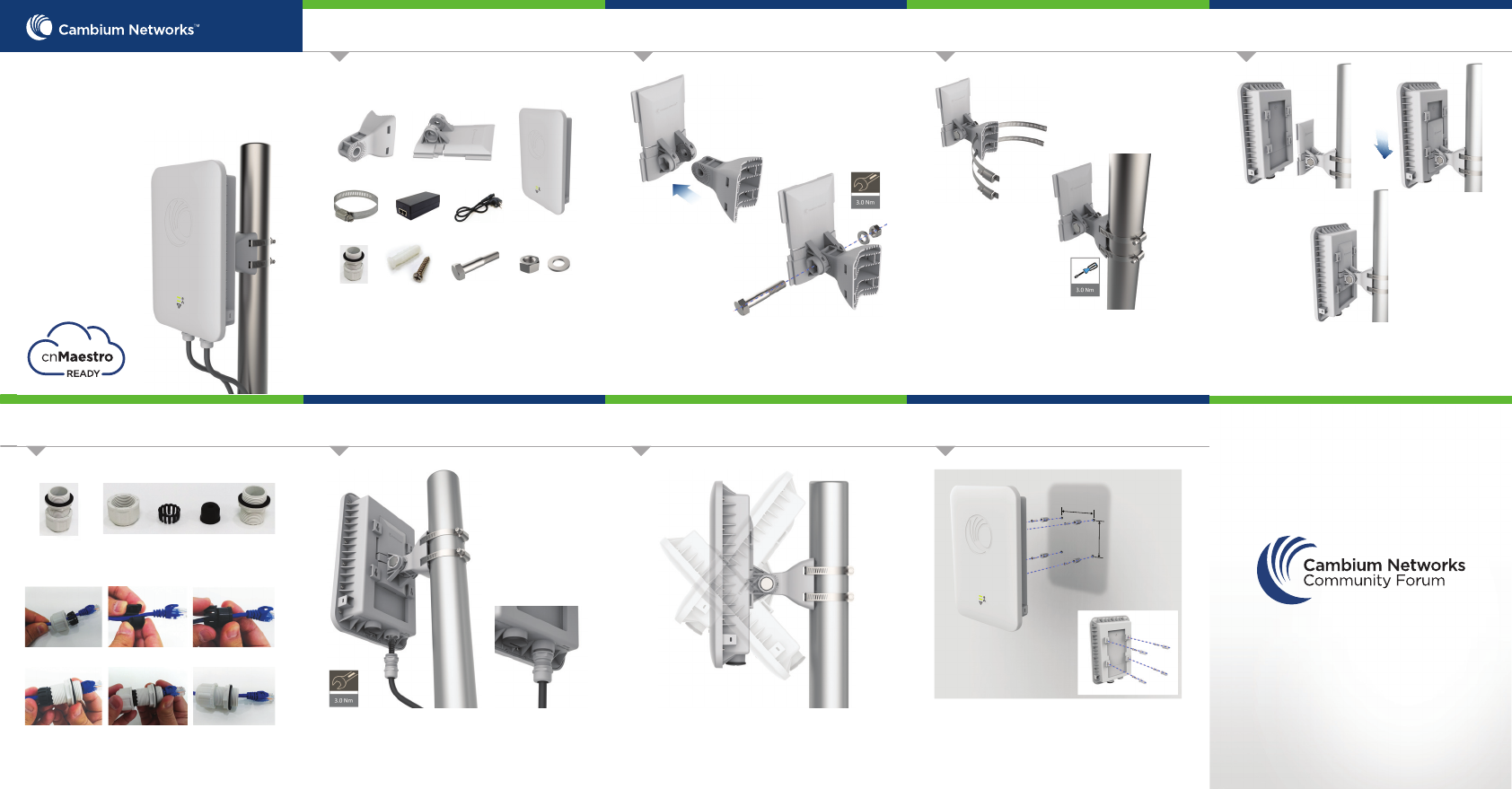
Drill 4 holes of Ø6mm (Ø0.25”Inch) on wall. Press fit
plastic anchor and assembly fastener. Leave 5mm to
6mm gap between wall and fastener head.
Use the four mounting slots given on the back of the
radio to mount to the wall.
Introduction
Tool Requirements
• Phillips screwdriver (Wall Mounting)
• Flat head screwdriver (Pole Mounting)
• 12 mm wrench (Pole Mounting)
community.cambiumnetworks.com
JOIN THE CONVERSATION
This guide provides quick installation steps for cnPilot F4
Access Points (APs).
Package Contents
Pole mounting bracket
PoE Injector
Cable gland
H6 Access Point
Align Radio to required angle by tilting up and down.
The maximum radio tilting angle is ± 40°, with an
incremental of 10°.
Radio holder
Hose clamp
(Qty. 2)
Power Cord
Quick Start
Guide
Tools Required
Wall mounting kit
(Qty. 4)
M12 x 60 Bolt M12 Nut & Washer
STEP 1 (Pole Mount)
Assemble the radio holder to the pole mounting bracket
and secure it with M8 nuts by applying 3.0 Nm torque.
STEP 2 (Pole Mount)
Insert hose clamps through pole mounting bracket and
clamp to pole by applying 3.0 Nm torque.
STEP 3 (Pole Mount)
Align the radio chassis with the guide rails of radio
holder and slide it downwards until it clicks into place.
Cable gland components
Components
Gland Assembly
Cable gland assembly sequence
Cap Plastic Seal Body
6. Assembled cable gland.5. Assemble cap and body.
4. Insert seal into body.
3. Insert seal into the plastic.2. Put seal over the cable.
1. Pass cable through cap.
STEP 4 STEP 5 (Pole Mount)
Insert RJ45 to radio housing and the lock cable gland to
radio housing with 1.5Nm to 2Nm torque.
STEP 6 (Radio alignment) Wall Mounting
cnPilot H6
DF:/$16HFWRU$FFHVV3RLQW
,3,QGXVWULDO*UDGH*LJDELW:L)L
108
100
Quick Link Setup
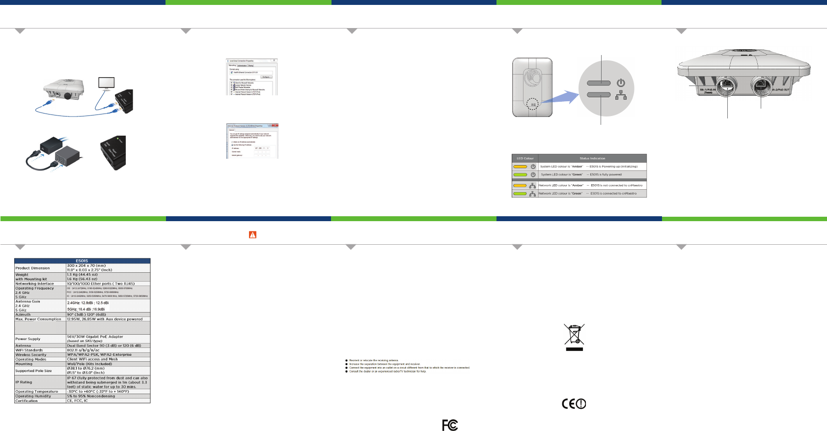
Configure Management PC Hardware Overview
Hardware Overview
Powering Up
Online Resources
Using a web browser, navigate to 169.254.1.1 and login with
username: admin and password: admin
Navigate to the Quick Start menu and click the ‘Go To Next Page’.
Configure your Region and Country of operation. Click the ‘Go To
Next Page’.
Configure the Carrier Frequency. Click the ‘Go To Next Page’.
Select the Synchronization source. Click the ‘Go To Next Page’.
Configuration - IP Address, a Subnet Mask, and a Gateway IP
Address OR DHCP state to Enabled to have the IP address, subnet
mask, and gateway IP address automatically configured by a
DHCP server. Click the ‘Go To Next Page’.
Click the ‘Save Changes’ button. Click the ‘Reboot’ button.
1.
2.
3.
4.
5.
6.
7.
1.
2.
3.
Connect the Ethernet cable from Eth1/PoE-IN of HV to the PoE
port of Gigabit Data + Power
Connect an Ethernet cable from your LAN or Computer to the
Gigabit Data port of the PoE adapter.
Connect the Power Cord to the adapter, and then plug the Power
Cord into a power outlet.
Once powered ON -- Power LED should illuminate continuously on
PoE Adapter.
**Shielded Category 5 (or above) cabling should be used for all
outdoor wired Ethernet connections and should be grounded
through the AC ground of the PoE.
RoHS/WEEE Compliance
Caring for the Environment: RoHS/WEEE
European Directive 2002/96/EC requires that the equipment bearing this symbol on
the product and/or its packaging must not be disposed of with unsorted municipal
waste. The symbol indicates that this product should be disposed of separately from
regular household waste streams. It is your responsibility to dispose of this and
other electric and electronic equipment via designated collection facilities
appointed by the government or local authorities. Correct disposal and recycling will
help prevent potential negative consequences to the environment and human
health. For more detailed information about the disposal of your old equipment,
please contact your local authorities, waste disposal service, or the shop where you
purchased the product.
CE Marking
CE marking on this product represents the product is in compliance with all
directives that are applicable to it.
Alert Sign (!) Follows CE Marking
Alert sign must be indicated if a restriction on use applied to the product and it
must follow the CE marking.
FCC Compliance
Changes or modifications not expressly approved by the party responsible for
compliance could void the user’s authority to operate the equipment.
7KLVGHYLFHFRPSOLHVZLWK3DUWRIWKH)&&5XOHV2SHUDWLRQLVVXEMHFWWRWKHIROORZLQJWZR
FRQGLWLRQV7KLVGHYLFHPD\QRWFDXVHKDUPIXOLQWHUIHUHQFHDQGWKLVGHYLFHPXVW
DFFHSWDQ\LQWHUIHUHQFHUHFHLYHGLQFOXGLQJLQWHUIHUHQFHWKDWPD\FDXVHXQGHVLUHGRSHUDWLRQ
)&&5DGLDWLRQ([SRVXUH6WDWHPHQW
7KLVHTXLSPHQWFRPSOLHVZLWK)&&UDGLDWLRQH[SRVXUHOLPLWVVHWIRUWKIRUDQXQFRQWUROOHG
HQYLURQPHQW7KLVHTXLSPHQWVKRXOGEHLQVWDOOHGDQGRSHUDWHGZLWKPLQLPXPGLVWDQFHFP
EHWZHHQWKHUDGLDWRU\RXUERG\
7KLVHTXLSPHQWKDVEHHQWHVWHGDQGIRXQGWRFRPSO\ZLWKWKHOLPLWVIRUD&ODVV%GLJLWDO
GHYLFHSXUVXDQWWR3DUWRIWKH)&&5XOHV7KHVHOLPLWVDUHGHVLJQHGWRSURYLGHUHDVRQDEOH
SURWHFWLRQDJDLQVWKDUPIXOLQWHUIHUHQFHLQDUHVLGHQWLDOLQVWDOODWLRQ7KLVHTXLSPHQWJHQHUDWHV
XVHVDQGFDQUDGLDWHUDGLRIUHTXHQF\HQHUJ\DQGLIQRWLQVWDOOHGDQGXVHGLQDFFRUGDQFHZLWK
WKHLQVWUXFWLRQVPD\FDXVHKDUPIXOLQWHUIHUHQFHWRUDGLRFRPPXQLFDWLRQV+RZHYHUWKHUHLV
QRJXDUDQWHHWKDWLQWHUIHUHQFHZLOOQRWRFFXULQDSDUWLFXODULQVWDOODWLRQ,IWKLVHTXLSPHQWGRHV
FDXVHKDUPIXOLQWHUIHUHQFHWRUDGLRRUWHOHYLVLRQUHFHSWLRQZKLFKFDQEHGHWHUPLQHGE\
WXUQLQJWKHHTXLSPHQWRIIDQGRQWKHXVHULVHQFRXUDJHGWRWU\WRFRUUHFWWKHLQWHUIHUHQFHE\
RQHRIWKHIROORZLQJPHDVXUHV
This radio transmitter (;)'5) has been approved by FCC to operate with the
antenna types listed below with the maximum permissible gain and required
antenna impedance for each antenna type indicated. Antenna types not included in
this list, having a gain greater than the maximum gain indicated for that type, are
strictly prohibited for use with this device.
Antenna Information: Dual-band dual-polarized antenna
)RUSURGXFWDYDLODEOHLQWKH86$&DQDGDPDUNHWRQO\FKDQQHOaFDQEHRSHUDWHG
6HOHFWLRQRIRWKHUFKDQQHOVLVQRWSRVVLEOH
3URIHVVLRQDOLQVWDOODWLRQLVUHTXLUHG
7KLVGHYLFHDQGLWVDQWHQQDVPXVWQRWEHFRORFDWHGRURSHUDWLQJLQFRQMXQFWLRQZLWKDQ\
RWKHUDQWHQQDRUWUDQVPLWWHU
Safety Notice
Warning:
To prevent loss of life or physical injury, observe the following safety guidelines. In no
event shall Cambium Networks be liable for any injury or damage caused during the
installation of H6 platform. Ensure that only qualified personnel install.
Only use attachments/accessories specified by the manufacturer.
Electrical Safety Information
Compliance with manufacturer’s label for voltage, frequency, and current
requirements. Connecting to a dierent power source than those specified may
result in improper operation, damage to equipment or pose a fire hazard if the
limitations are not followed.
There are no serviceable parts inside this equipment. Service should be
provided only by a qualified service technician.
This equipment is provided with a detachable power cord which has an integral
safety ground wire intended for connection to a grounded safety outlet.
Do not substitute the power cord with one that is not the provided
approved type. Never use an adapter plug to connect to a 2-wire outlet
as this will defeat the continuity of the grounding wire.
The equipment requires the use of the ground wire as a part of the safety
certification, modification or misuse can provide a shock hazard that can
result in serious injury or death.
Contact a qualified electrician or the manufacturer if there are questions
about the installation prior to connecting the equipment.
Protective earthing is provided by Listed AC adapter. Building installation
shall provide appropriate short-circuit backup protection.
Protective bonding must be installed in accordance with local national
wiring rules and regulations.
1.
2.
3.
a.
b.
c.
d.
e.
Select Properties for the Ethernet port. In Windows it is found in
Control Panel > Network and Internet > Network Connections > Local
Area Connection.
IP Address Configuration
Default IP address received via DHCP.
cn Pilot H6 will use a default static IP address of 192.168.0.1, If
there is no DHCP server
Default Login information
- Username: admin
- Password: admin
Management Protocols enabled by default –http or https (webpage
management interface access), SSH (CLI management interface access).
1.
2.
3.
Specifications
Secondary Port
The Secondary port is a Gigabit Ethernet port used for bridging.
Reset
The Reset button serves two functions for H6:
- To restart, press and release the Reset button quickly.
- To restore to factory default settings, press and hold the
Reset button for more than 10 seconds.
Main Port
The Main port is a Gigabit Ethernet port used to connect the power and
should be connected to the LAN and DHCP server.
Main Port
Reset Button
Secondary Port
System LED
Network LED
User Guide and software downloads:
https://support.cambiumnetworks.com/files/e500/
Support:
http://www.cambiumnetworks.com/support/
Contact us:
http://www.cambiumnetworks.com/support/contact-support/
,C Compliance
7KLVGHYLFHFRPSOLHVZLWK,QGXVWU\&DQDGDOLFHQVHH[HPSW566VWDQGDUGV2SHUDWLRQLVVXEMHFW
WRWKHIROORZLQJWZRFRQGLWLRQVWKLVGHYLFHPD\QRWFDXVHLQWHUIHUHQFHDQGWKLVGHYLFHPXVW
DFFHSWDQ\LQWHUIHUHQFHLQFOXGLQJLQWHUIHUHQFHWKDWPD\FDXVHXQGHVLUHGRSHUDWLRQRIWKHGHYLFH
/HSUpVHQWDSSDUHLOHVWFRQIRUPHDX[&15G,QGXVWULH&DQDGDDSSOLFDEOHVDX[DSSDUHLOVUDGLR
H[HPSWVGHOLFHQFH/H[SORLWDWLRQHVWDXWRULVpHDX[GHX[FRQGLWLRQVVXLYDQWHVODSSDUHLOQH
GRLWSDVSURGXLUHGHEURXLOODJHHWOXWLOLVDWHXUGHODSSDUHLOGRLWDFFHSWHUWRXWEURXLOODJH
UDGLRpOHFWULTXHVXELPrPHVLOHEURXLOODJHHVWVXVFHSWLEOHGHQFRPSURPHWWUHOHIRQFWLRQQHPHQW
)RUSURGXFWDYDLODEOHLQWKH86$&DQDGDPDUNHWRQO\FKDQQHOaFDQEHRSHUDWHG6HOHFWLRQRI
RWKHUFKDQQHOVLVQRWSRVVLEOH
3RXUOHVSURGXLWVGLVSRQLEOHVDX[eWDWV8QLV&DQDGDGXPDUFKpVHXOOHFDQDOjSHXYHQW
rWUHH[SORLWpV6pOHFWLRQGDXWUHVFDQDX[QHVWSDVSRVVLEOH
,&5DGLDWLRQ([SRVXUH6WDWHPHQW
7KLVHTXLSPHQWFRPSOLHVZLWK,&566UDGLDWLRQH[SRVXUHOLPLWVVHWIRUWKIRUDQXQFRQWUROOHG
HQYLURQPHQW7KLVHTXLSPHQWVKRXOGEHLQVWDOOHGDQGRSHUDWHGZLWKPLQLPXPGLVWDQFHFP
EHWZHHQWKHUDGLDWRU\RXUERG\
&HWpTXLSHPHQWHVWFRQIRUPHDX[OLPLWHVGH[SRVLWLRQDX[UD\RQQHPHQWV,&pWDEOLHVSRXUXQ
HQYLURQQHPHQWQRQFRQWU{Op&HWpTXLSHPHQWGRLWrWUHLQVWDOOpHWXWLOLVpDYHFXQPLQLPXPGHFP
GHGLVWDQFHHQWUHODVRXUFHGHUD\RQQHPHQWHWYRWUHFRUSV