Cambium Networks XR2425H 802.11abgn (2x2) access point for outdoor installations User Manual xirrus PDF
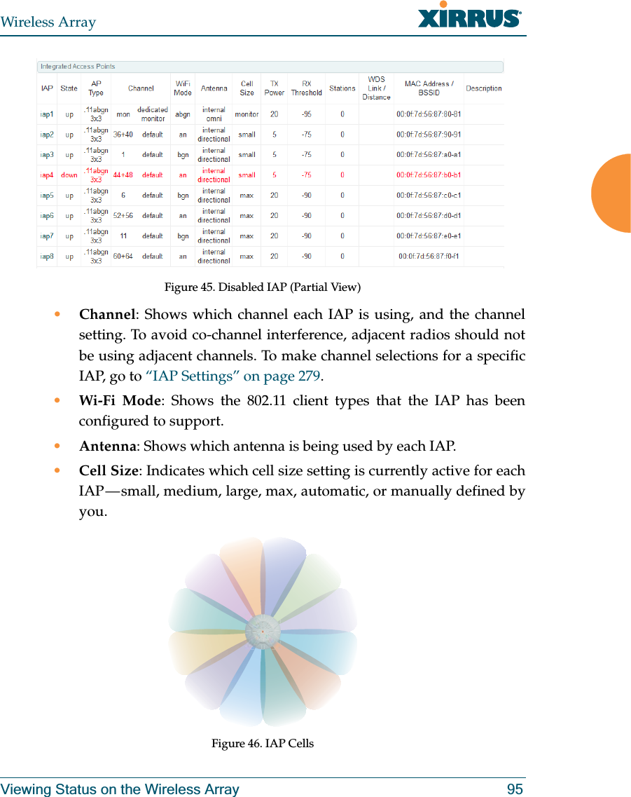
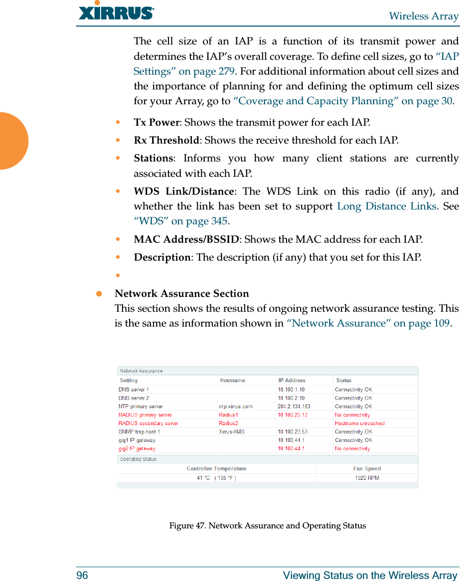
Xirrus, Inc. 802.11abgn (2x2) access point for outdoor installations xirrus PDF
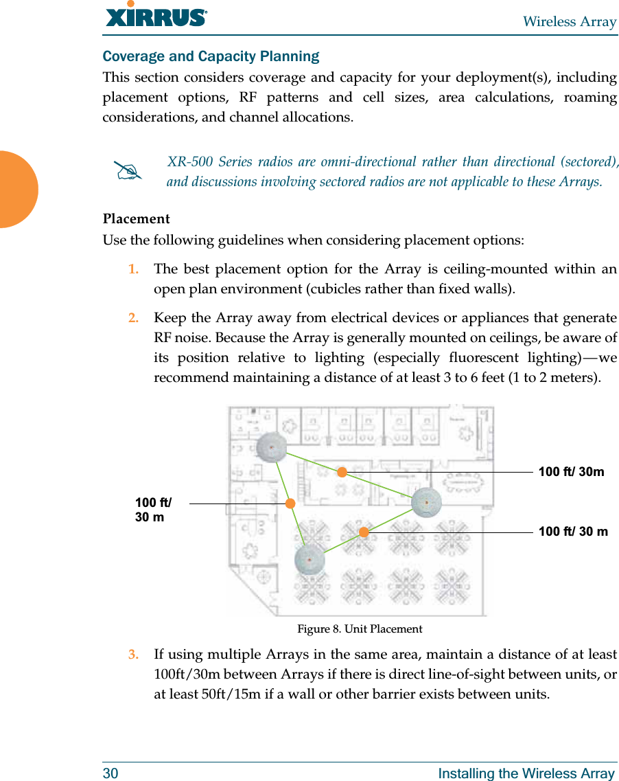
Contents
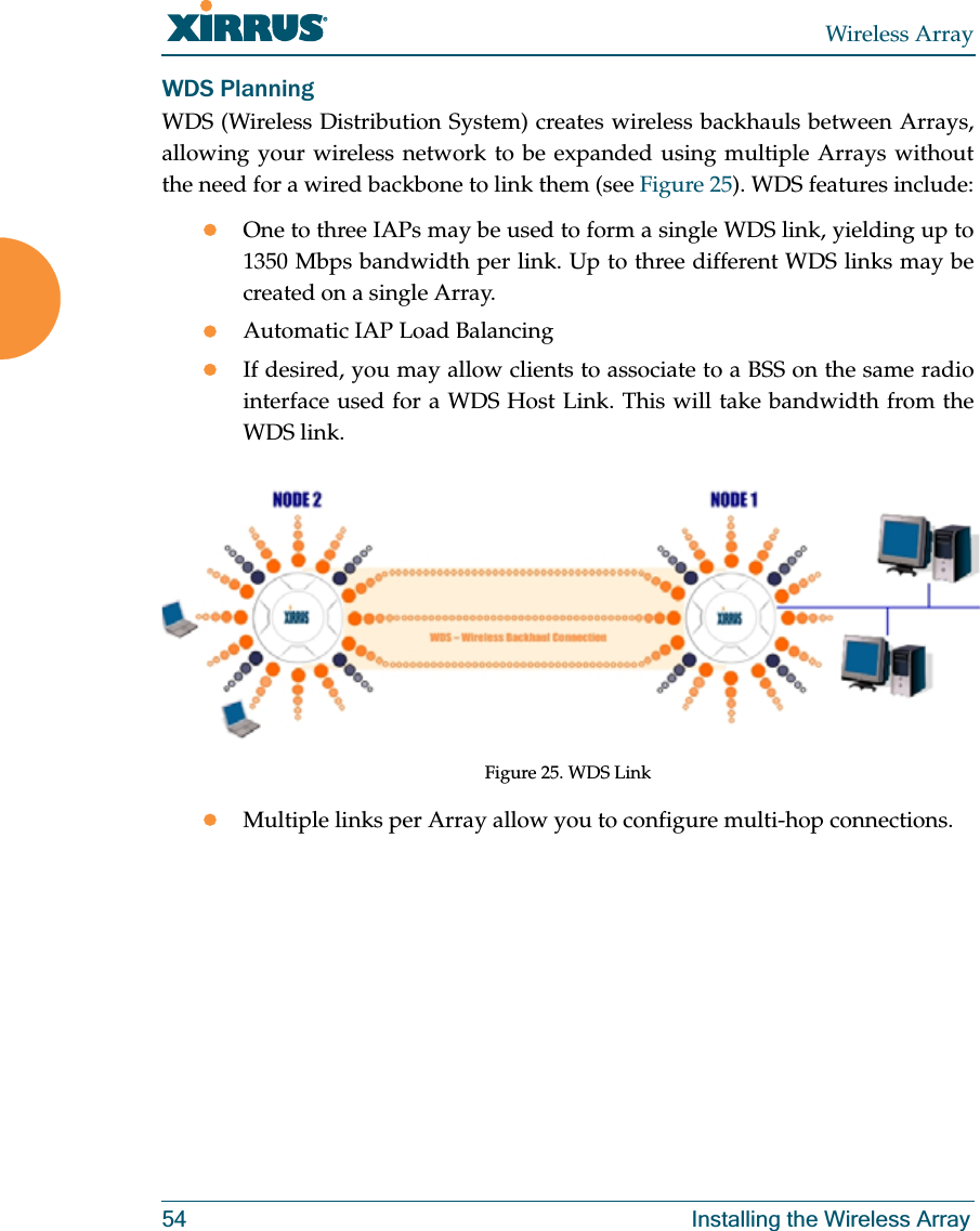
- 1. ArrayOS XR_User Guide_Rel_6.7a_RevJ (1of2)
- 2. ArrayOS XR_User Guide_Rel_6.7a_RevJ (2of2)
- 3. XR-2425H Quick Install Guide RevC
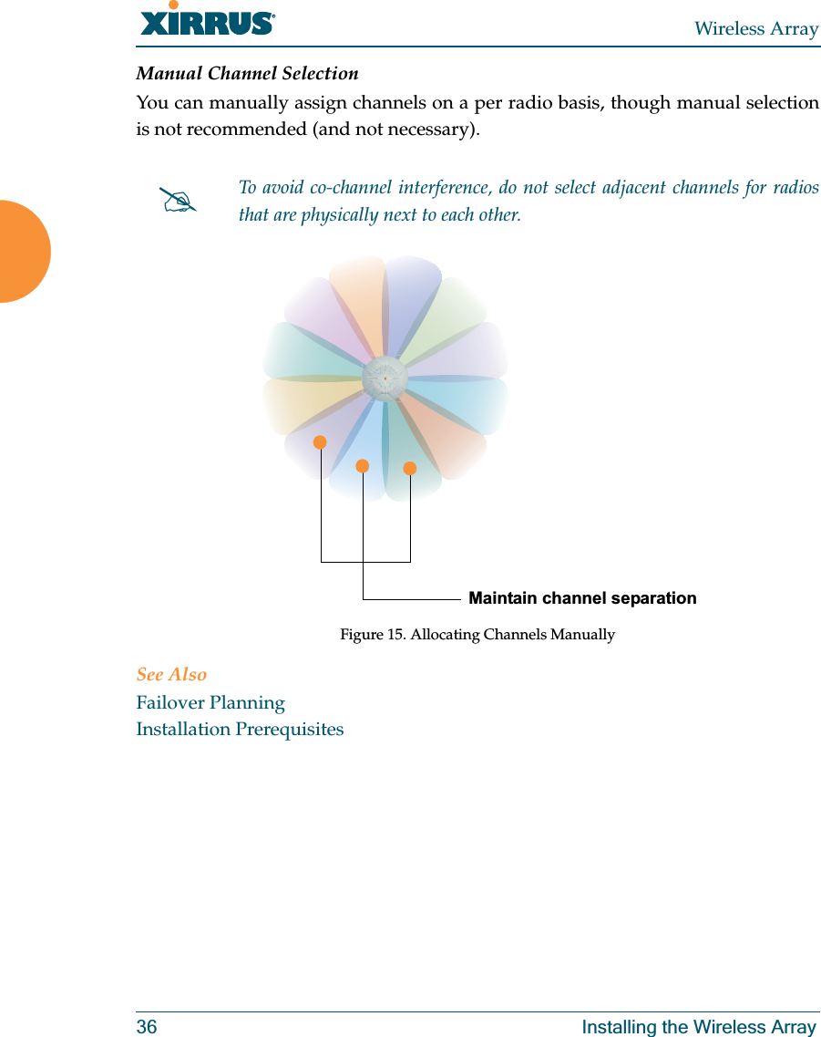
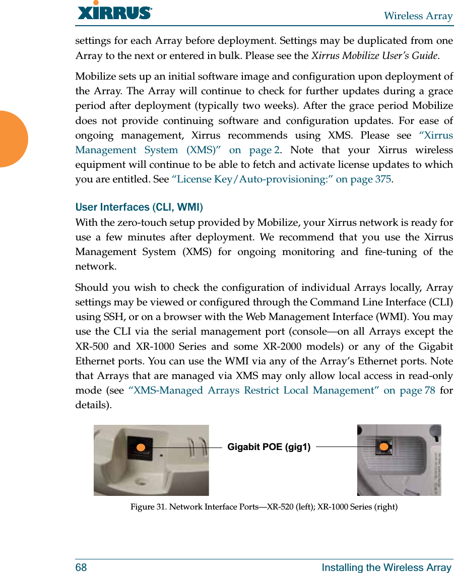
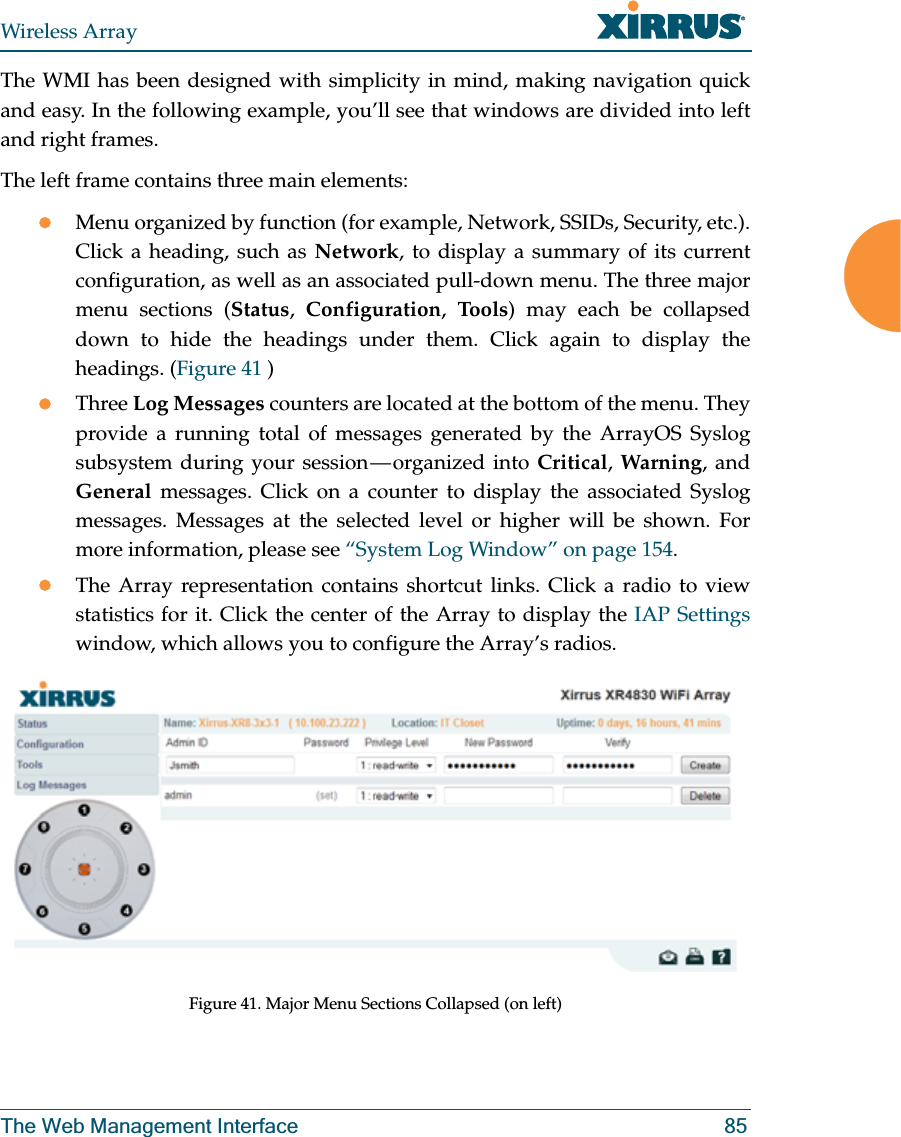
- 4. User Manual
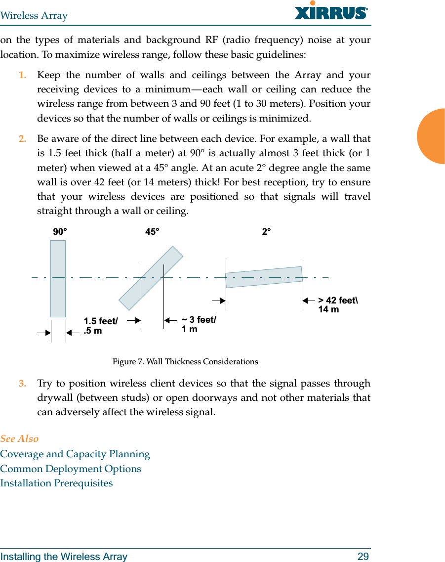
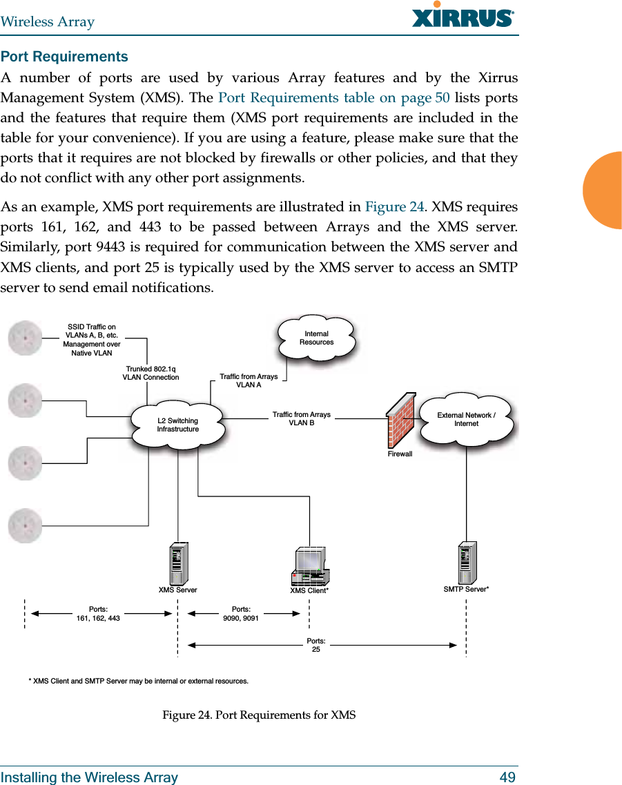
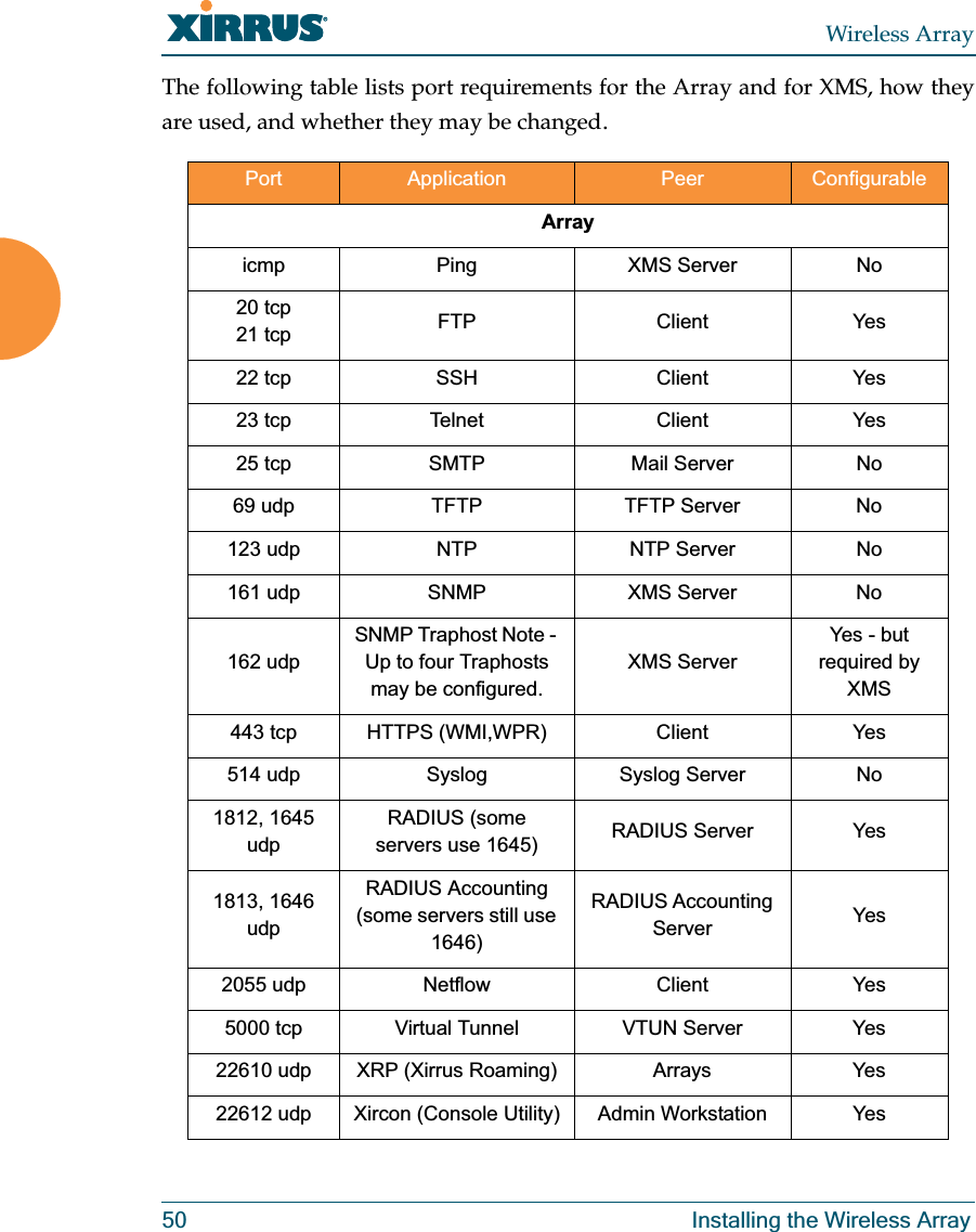
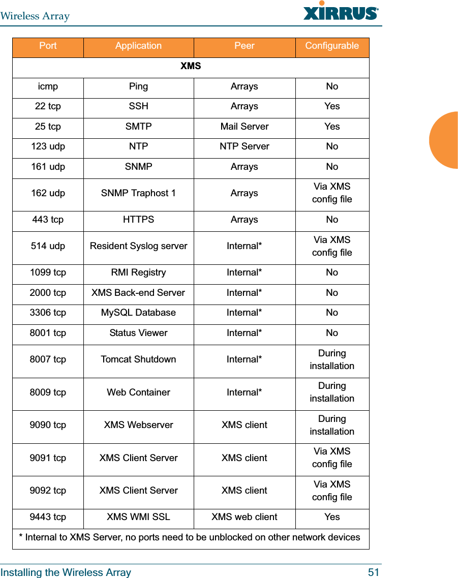
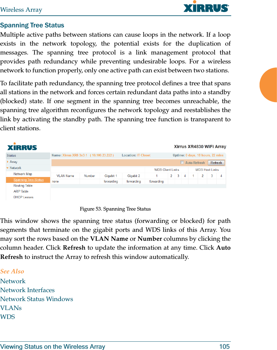
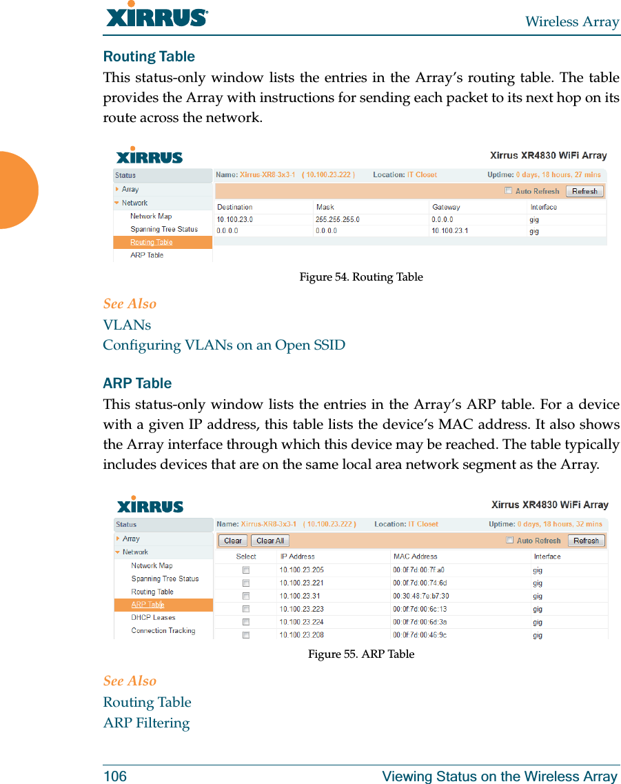
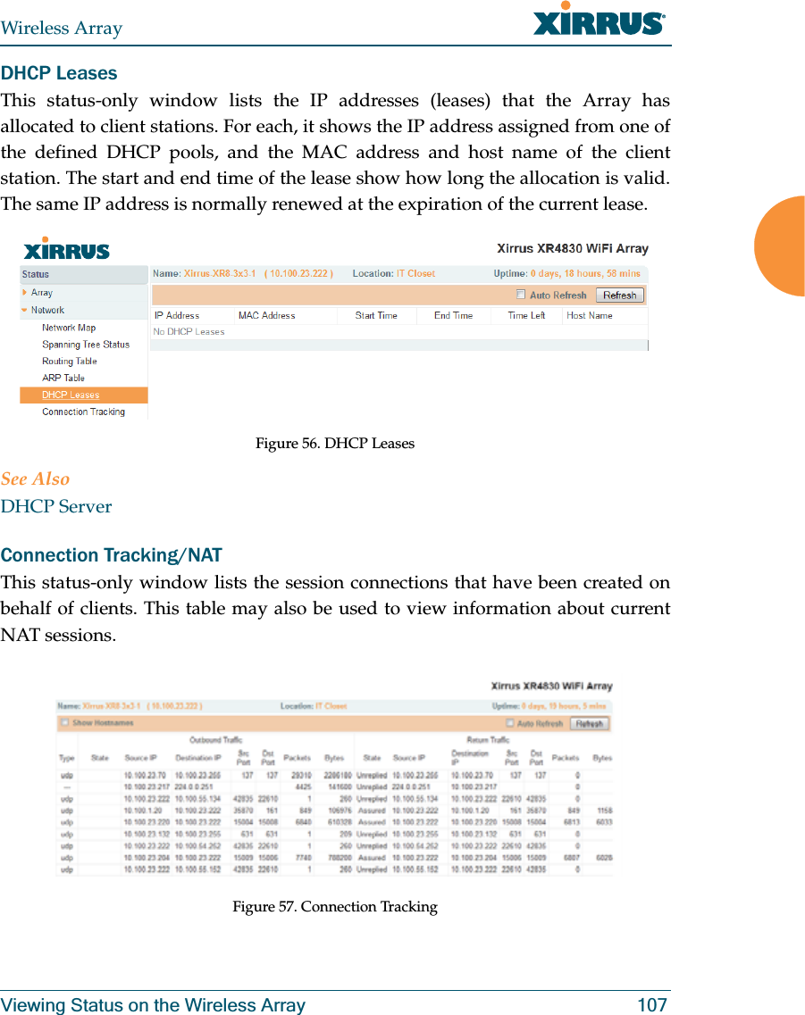
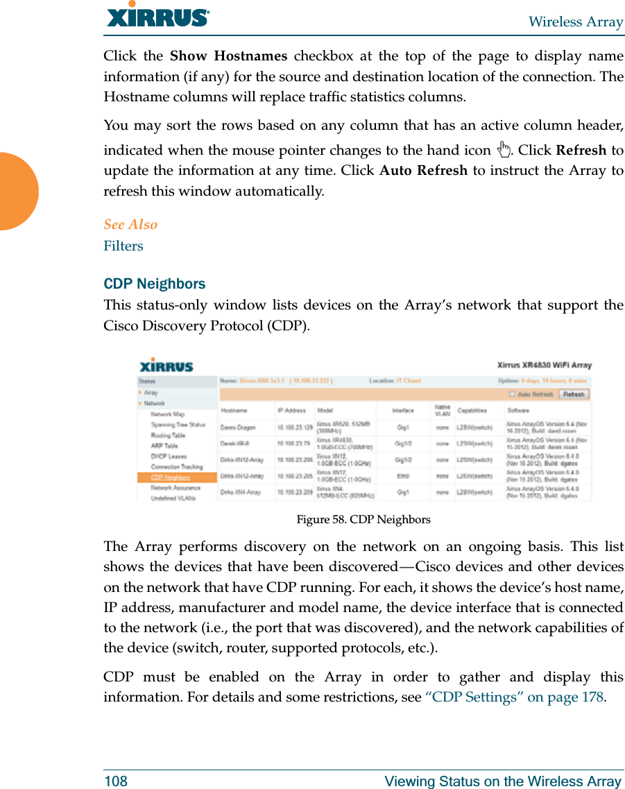
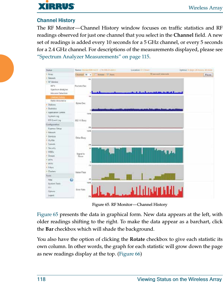
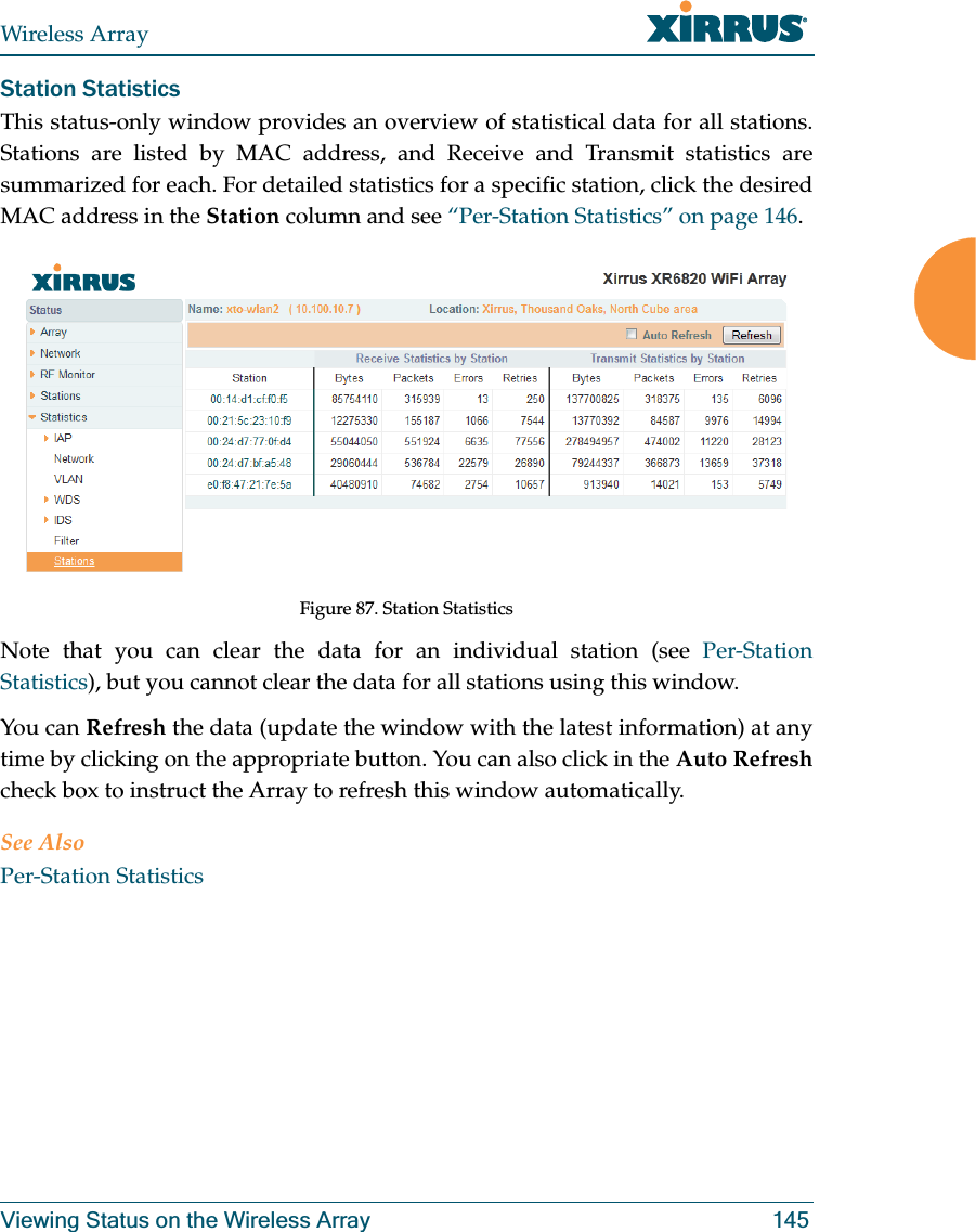
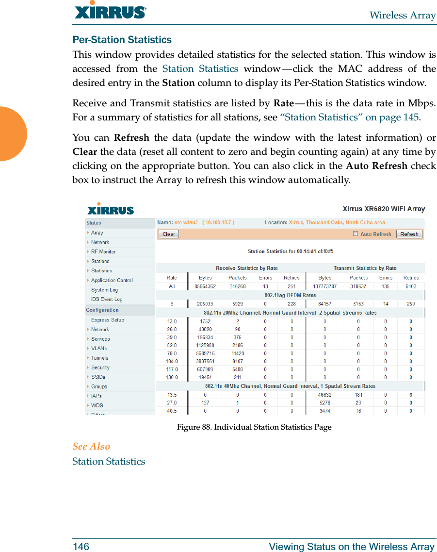
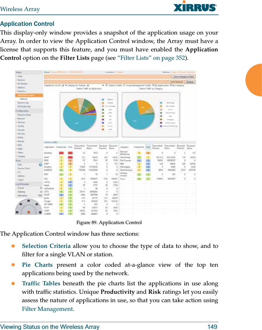
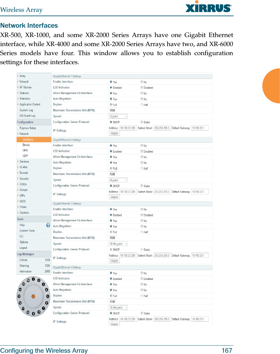
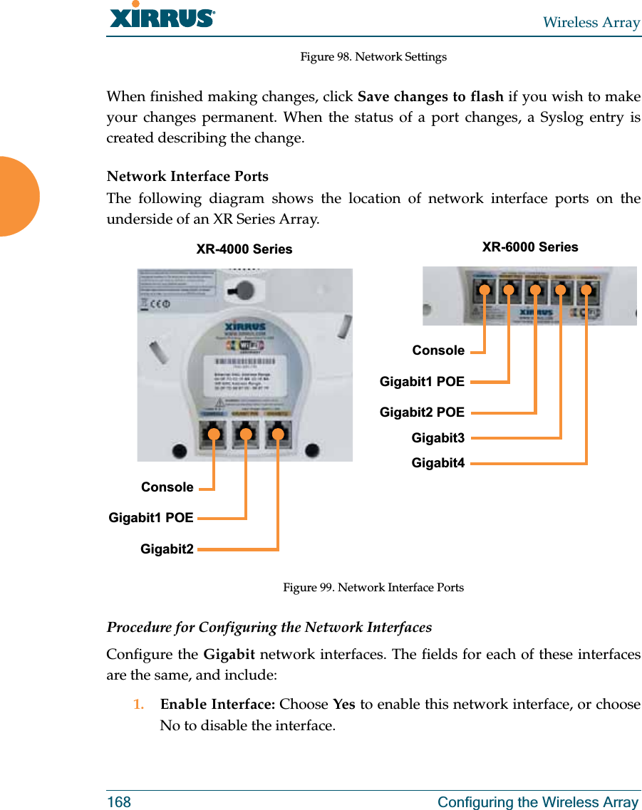
ArrayOS XR_User Guide_Rel_6.7a_RevJ (1of2)