Cambium Networks XR520H Hardened Wireless Access Point User Manual
Xirrus, Inc. Hardened Wireless Access Point
Contents
User Manual.pdf

QUICK INSTALLATION GUIDE
XR Series
Wireless Access Points
April 29, 2013
XR520H

XR5 2 0 H Qu ick I nst a llat ion Guide
is a registered trademark of Xirrus, Inc. All other trademarks and brand names are
marks of their respective holders.
All rights reserved. This document may not be reproduced or disclosed in whole or in part by
any means without the written consent of Xirrus, Inc.
Please see Warranty and License Agreements in the Wireless Array User’s Guide.
Document Part Number: 812-0085-005 Revision A April, 2013

XR5 2 0 H Qu ick I nst a llat ion Guide
XR520H Quick Installation Guide
The XR520H Hardened Wireless Access Point provides Xirrus
wireless technology in a hardened case for installation outdoors and
in other harsh environments. This guide describes how to install the
XR520H on a pole or wall and execute the initial power up of the
Access Point. The pole or wall can be a structure that is installed at
ground level or on a roof. The XR520H is not compatible with other
Xirrus mounting options. For additional information, see the Wireless
Array User’s Guide.
This document is intended ONLY for XR520H model Access Points. For other XR
models please see the Quick Installation Guide for that model series.
1) You Need the Following Items
Accessory Kit (included in each Wireless Access Point carton) includes:
o Mounting bracket and mounting screw
o Grounding cable and short ground wire
o Watertight RJ connector assembly
Appropriate tools, bands, screws, and/or anchors required for the desired mounting location
(not provided with the Access Point).
Workstation with a Web browser to configure the Wireless Access Point.
RJ-45 Ethernet connection(s) to your wired network.
Power—XR520H Access Points are powered via Power over Gigabit Ethernet (PoGE) using
an outdoor-rated Ethernet Cat 5e or Cat 6 cable that also carries data traffic. Only Xirrus-
supplied power injectors, or 802.3af or 802.3at PoE-compliant switches, may be used to
power the XR520H . The XR520H is powered by one injector port rated at 20W or higher.
The Xirrus PoGE Power Injector requires an AC outlet. See the PoGE Installation Guide for
more information.
NOTE: Xirrus PoGE Injectors must be installed and used indoors.
2) Choose a Suitable Location
The XR520H is tested to IP65 water proof and dust proof requirements to protect against
severely wet and dusty environments. For optimal placement, we recommend that a predictive
survey be performed by a qualified Xirrus partner.
Choose a location that is not subjected to submersion.
Direct sunlight may raise the effective ambient temperature many degrees above the air
temperature. It is best to choose a location that has some level of protection from the sun.
- 1 -
XR5 2 0 H Qu ick I nst a llat ion Guide
The maximum cable length between the XR520H and the RJ-45 Ethernet Network is 100
meters. The PoGE Injector is not a repeater, so its location will not increase this distance.
The XR520H can operate from a Wireless Distribution System (WDS) link. However, the
unit will need to be configured via the Ethernet connection prior to mounting and power
must still be supplied via the RJ-45 Ethernet connector.
Keep the unit away from electrical devices or appliances that generate RF noise—at least 3
to 6 feet (1 to 2 meters).
3) Prepare the Mounting Location
Part of the mechanical installation is to ensure that the Access Point is grounded to earth
ground to dissipate any static electric charge that may develop due to wind.
Determine a good electrical earth ground point near the Access Point mounting location. If
an earth ground point is not available, consult an electrician to have one installed.
Crimp a terminal lug to a sufficient length of 16 gauge wire to reach from the mounted
Access Point to the earth ground point.
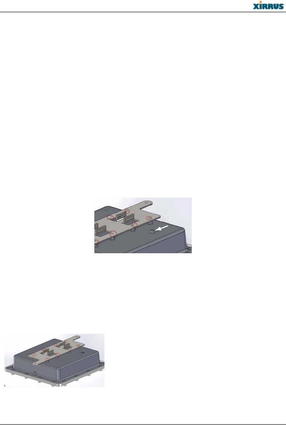
Before the Access Point is attached to a wall or pole, secure the terminal lug to the Access
Point with the #6 screw provided in the location indicated by the white arrow, below..
4) Attach the Mounting Plate to the Access Point
The accessory kit includes a small mounting plate. Mounting plate dimensions are included in
the Drawings section at the end of this guide. The mounting plate can be used for wall or pole
mounting by reversing the side of the plate exposed. Attach the mounting plate to the Access
Point using the eight provided screws in the locations indicated below (secure in at least 4
places). The Pole Mounting position of the bracket is shown below.
For Pole Mounting:
For Wall M ount ing:
- 2 -
XR5 2 0 H Qu ick I nst a llat ion Guide
5) Mount the Access Point on a Pole or Wall
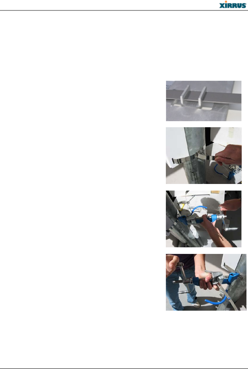
5a) Pole Mounting
For pole mounting, Xirrus recommends using metal straps (not included with the Access Point).
The metal straps can be obtained from BAND-IT-IDEX, Inc. (www.BAND-IT-IDEX.com). See
their web site for additional contact information. Complete the following steps to mount the
Access Point to a pole.
Install the metal bands through the holes in the mounting
bracket.
Hand tighten the Band-It strap through the pole mounting
bracket, thread it through the strap buckle and then bend
the strap back.
Using the Band-It tool, place the tool onto the strap.
Rotate the Band-It tool so that it can pull the excess strap
through the buckle and turn the crank until the strap is very
tight.
- 3 -
XR5 2 0 H Qu ick I nst a llat ion Guide
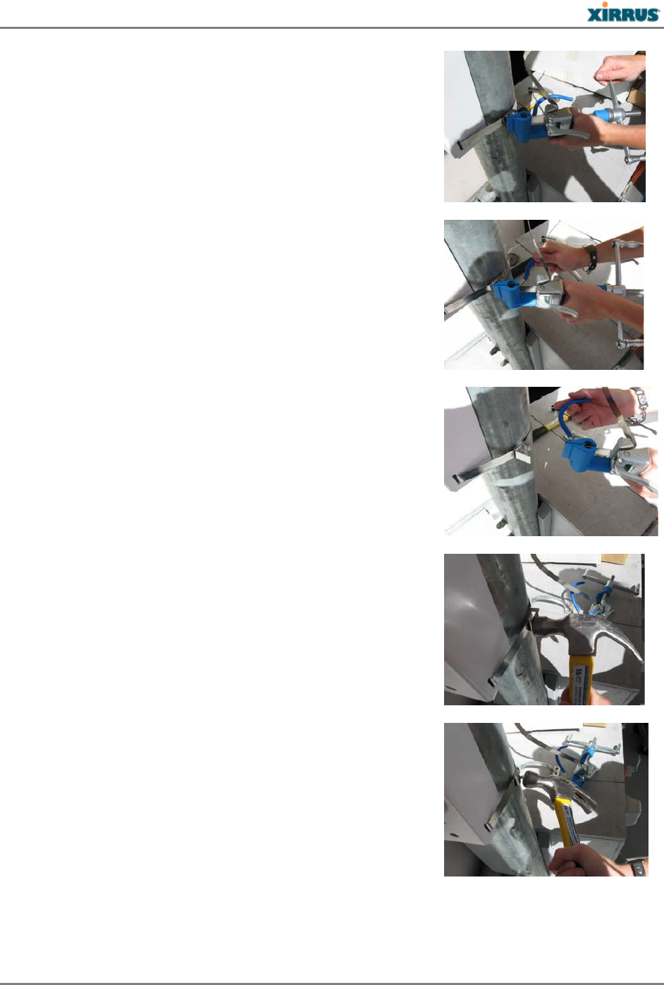
Once the strap is satisfactorily tight, rotate the Band-It tool
back so that the strap cannot slide back through the buckle.
Using the built in cutting tool on the Band-It tool, cut the
excess strap.
Your installation should now appear as shown here.
Using a hammer, bend back and flatten the remaining strap.
Using a hammer, bend and flatten the two tabs on the
buckle, so that they hold the flattened strap end in place.
- 4 -

XR5 2 0 H Qu ick I nst a llat ion Guide
The completed attachment should have the mounting bracket firmly seated against the pole.
One band should be enough for most installations however a second band can be used for
additional mounting security.
5b) Wall Mounting
Place the Access Point in the desired location and mark the location of the mounting holes
on the wall.
Drill and prepare the holes for the desired screw type. In metal walls the holes may be
tapped to the proper thread or alternatively the Access Point may be mounted with sheet
metal screws. For concrete walls a plastic anchor and screw are suggested.
NOTE: Mounting screws for attaching the plate to the wall are not provided in the kit.
Attach the Access Point to the mounting plate before attaching the mounting plate to the
wall.
6) Ground to Earth Ground
WARNING: This equipment must be externally grounded using a customer-supplied
ground wire before power is applied. Contact the appropriate electrical inspection
authority or an electrician if you are uncertain that suitable grounding is available.
Part of the mechanical installation is to insure that the Access Point is grounded to earth ground
to dissipate any static electric charge that may develop due to wind. In Step 3, you secured a
terminal lug to the Access Point with the provided #6 screw (see Step 3 if this has not been
done).
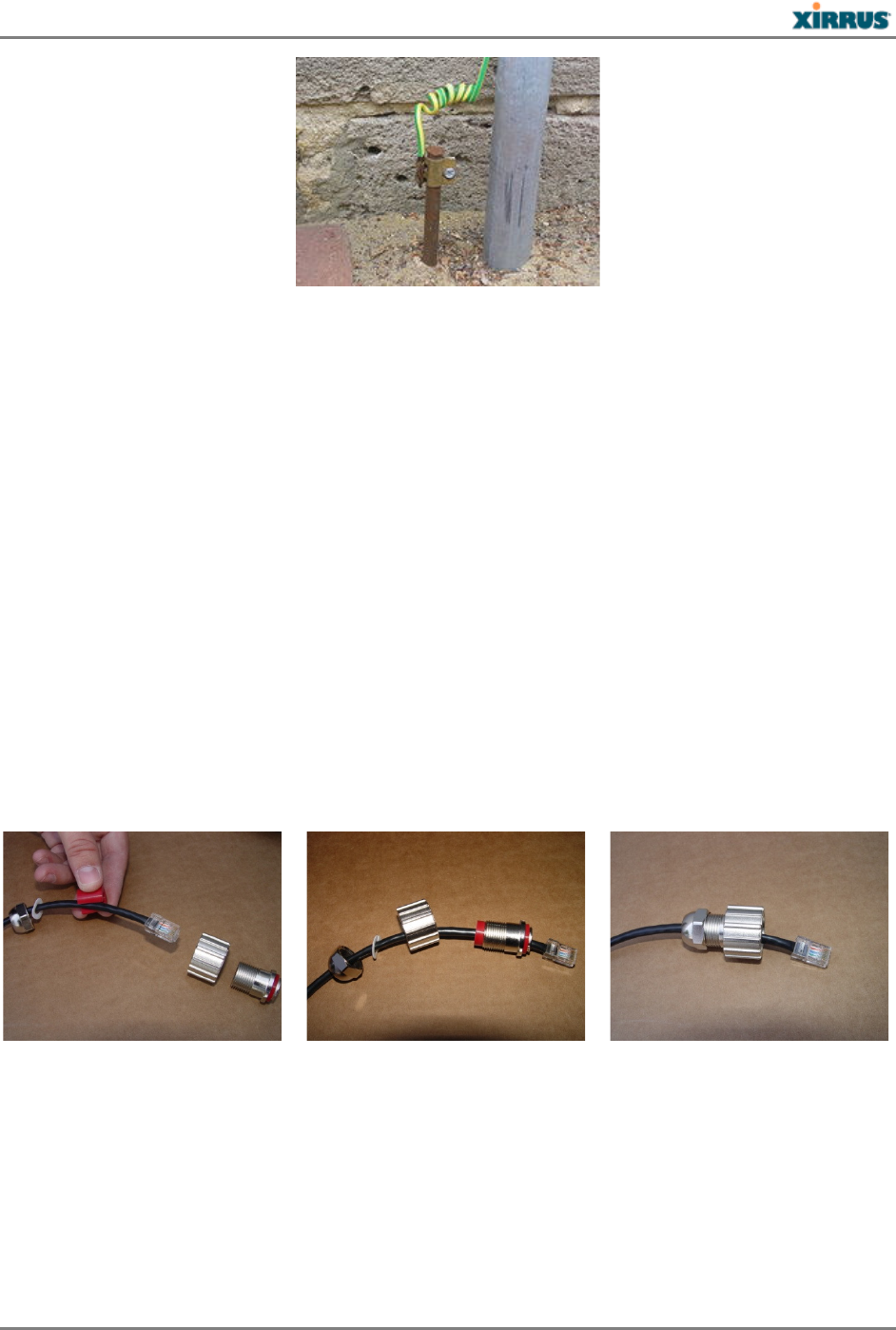
After Step 3 is completed and the Access Point is mounted to the wall or pole, attach the 16
gauge wire from the Access Point to the electrical earth ground point that you located or
had installed in Step 3. The following illustration shows an earth ground connection where
the Access Point is mounted on a pole at ground level and the 16 gauge wire is attached to a
stake driven into the ground.
- 5 -
XR5 2 0 H Qu ick I nst a llat ion Guide
Continue the installation by mounting the antenna and attaching the cables as described in
Steps 7, 8, and 9.
7) Install an Antenna
NOTE: Use only Xirrus-approved or recommended external antennas. Also see the
Notices and Warnings regarding external antennas in the Warning & Notices section of
this guide.
NOTE: Be sure to configure the Access Point’s IAPs to the proper bands (2.4 GHz and
5.0 GHz) in Step 11. Each must match the band of the antenna to which it is connected.
Low loss cable is available such that the antenna can be mounted in an appropriate location that
could be several feet away from the Access Point.
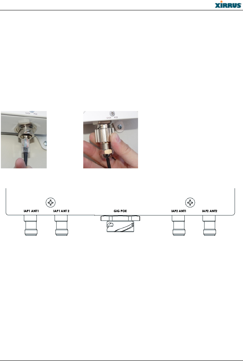
8) Prepare the Ethernet Cable with the Waterproof Shell
Place the split washer and split rubber grommet over the cable.
Slide all the sections together and tighten the nut on the end to 5kg but not more than 8kg
torque force to insure a water tight fit.
- 6 -
XR5 2 0 H Qu ick I nst a llat ion Guide
9) Connect the Cables
9a) POE port
All XR520H Access Points are powered directly via their Gigabit Ethernet connection.
Power: These Access Points are only powered through the GIG POE port. Only Xirrus-
supplied power injectors, or 802.3af or 802.3at PoE-compliant switches, may be used to
power the XR520H.
Data: Data is supplied to the Gigabit port via the same cable that powers the Access Point.
Connect the outdoor-rated Ethernet cable carrying data and power from the PoGE injector
to the Access Point’s GIG POE port as indicated.
9b) Antenna ports
Both IAP1 cables from the Access Point (IAP1 ANT1 and IAP1 ANT2) must be attached to
connectors for the same frequency band on the antenna (e.g., 2.4GHz), and IAP1 must be
assigned to that band on the Access Point (see Step 11). Similarly, both IAP2 cables need to go to
the other frequency band on the antenna (e.g., 5.8GHz). For simplicity, we suggest that you
connect IAP1 (ANT1 and ANT2) to 2.4GHz on the antenna, and connect IAP2 (ANT1 and
ANT2) to 5.8GHz. Then you must configure the Access Point to correspond in Step 11: set IAP1
to the 2.4GHz band and IAP2 to the 5GHz band.
To use a 3x3 MIMO antenna type with the XR520H, connect cables to the +45 and -45
connectors. Do not use the connector marked “V”.
The XR520H has RP-TNC connectors for the antenna.
- 7 -
XR5 2 0 H Qu ick I nst a llat ion Guide
10) Log In to the Access Point
NOTE: If you are a Xirrus Cloud customer, your Access Points are completely managed by
XMS Cloud, and you may skip all of the remaining steps (10, 11 and 12). In fact, you will
not be able to access CLI or the Web Management Interface under normal operating
circumstances.
Xirrus Cloud customers should wait five minutes, then log on to XMS Cloud to
view/manage this Access Point. In the event that your connection to the Cloud has been
interrupted for an extended period of time, you may contact Xirrus technical support for
help with local access to the Access Point.
Establish a network connection to the Access Point using a web browser. If you are using
DHCP and DNS, enter the Access Point's default host name in the URL field. The default
host name is its serial number (for example, XR0823090CACD).
If you are not using DNS and DHCP, enter the IP address in the URL field. Be aware of the
following:
− By default, the Access Point tries to obtain an IP address via DHCP. If it cannot do so,
the factory default is a static IP address of 10.0.2.1 with a mask of 255.255.255.0 on its
Gigabit POE port.
Take care to ensure that your network is not using the 10.0.2.1 IP address prior to
connecting the Access Point to the network.
− To connect to the Access Point in this case, you must set your computer to be in the same
subnet as the Access Point: set your IP address to be in the 10.0.2.xx subnet, and set its
subnet mask to 255.255.255.0. If this subnet is already in use on your network, you may
connect your computer directly to the Access Point by connecting the computer to the
power injector’s IN port temporarily (this port may be called the SWITCH port or the
DATA port on your injector).
− If the assigned IP address is unknown, you may use the Xirrus Xircon utility to
communicate with any XR520H on the local network. Note that the XR520H does not
have a console port, so Xircon has been specifically designed to substitute for the use of
a console port. See “Secure Low Level Access to the Access Point” in Step 12 for more
information about Xircon.
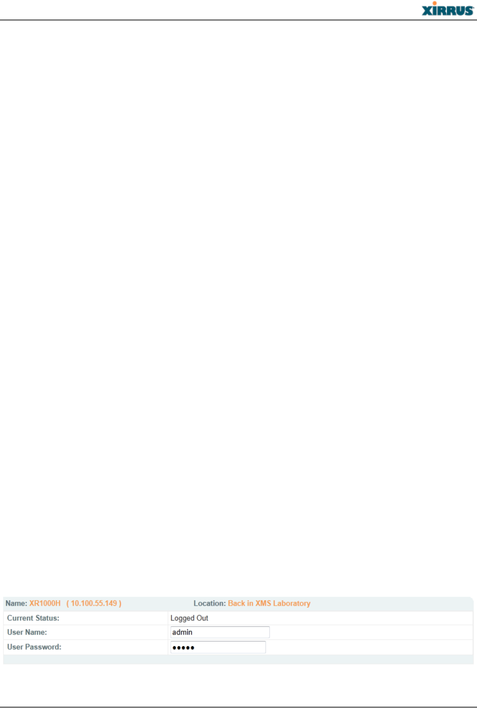
If your browser reports a Security exception, accept it and continue on to the Access Point’s
Web Management Interface (WMI).
At the login prompt, enter the default user name / password (the default is admin for both).
You are now logged in to the Wireless Access Point.
- 8 -
XR5 2 0 H Qu ick I nst a llat ion Guide
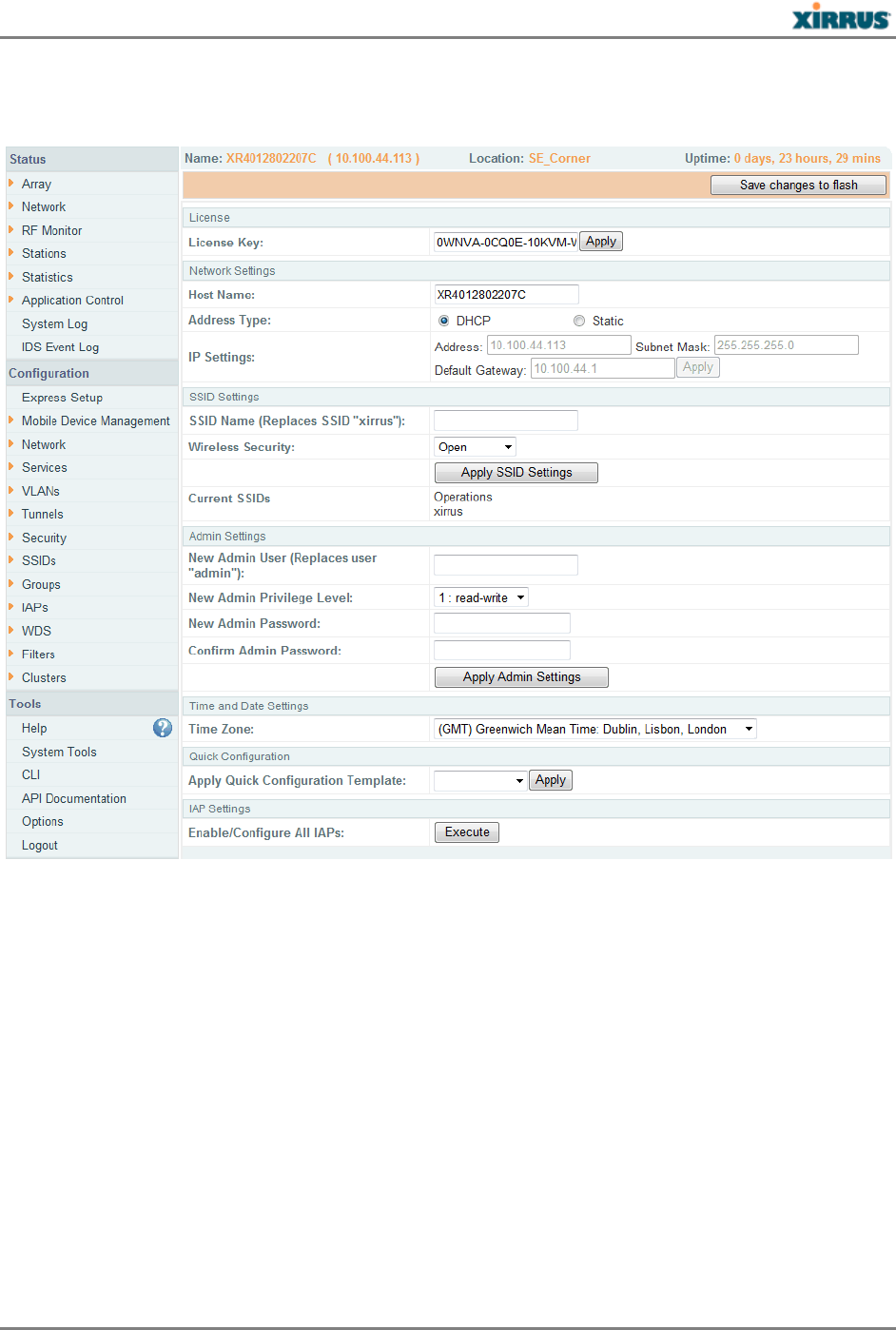
11) Configure the Access Point
Click Express Setup.
The Access Point will automatically contact Xirrus and obtain its license key, based on its
serial number and MAC address. This auto-licensing function requires the Access Point to
have an Internet connection. A license is needed to enable the full functionality of the Access
Point.
In the Admin Settings section, change both the default admin username and password to
improve Access Point security. Enter New Admin User and New Admin Password, then
Confirm Admin Password. Leave New Admin Privilege Level at read/write. Click Apply
Admin Settings when done.
Be sure to record the new account name and password, because the default admin user
will be deleted!
If you make changes to the SSID Settings section, click the associated Apply button to
apply your changes.
Click Save Changes to Flash on the upper right to save your settings.
- 9 -

XR5 2 0 H Qu ick I nst a llat ion Guide
Click Execute at the bottom of the page to set up/enable all IAPs (radios) automatically.
Be sure to configure the Access Point’s IAPs to the proper bands (2.4 GHz or 5.0 GHz), to
match the antenna connections that you made in Step 9b. Each must match the band of the
antenna to which it is connected.
Click IAPs > IAP Settings and select the correct value for each IAP in the Band column.
For improved security, you must also take the additional steps described in “Secure Low
Level Access to the Access Point” in Step 12.
With a basic configuration established the Wireless Access Point is now functional. Refer to
the Wireless Array User’s Guide for additional configuration information. Look for the section
titled Performing the Express Setup Procedure near the end of the Installing the Wireless Array
chapter of the Guide for more details on Express Setup settings. The chapter titled
Configuring the Wireless Array discusses all of the settings available for the Access Point.
Note: The channel set available in an outdoor application is different than indoor so
some channels typically used will not be shown.
12) Secure Low Level Access to the Access Point
Management of the Xirrus Access Point is done via the Web Management Interface (WMI) or
Command Line Interface (CLI). The Access Point also has a lower level interface: XBL (Xirrus
Boot Loader), which allows access to more primitive commands. You won’t normally use XBL
unless instructed to do so by Xirrus Customer Support. For proper security, you should replace
the default XBL login username and password with your own, as instructed below. XBL has its
own username and password, separate from the ArrayOS Admin User and Password (used for
logging in to the WMI and CLI).
Xirrus also provides the Xircon utility for connecting to Access Points that are not reachable via
the normal access methods (such as Secure Shell (SSH) or WMI) and that do not have a physical
console port (XR520H), or whose console port is not accessible. Xircon discovers Access Points
on your network subnet and can then establish an encrypted console session to the Access Point
via the network even if the Access Point IP configuration is incorrect. Xircon allows you to
manage the Access Point using CLI, just as you would if connected to the console port. Xircon
also has an option for easily accessing XBL.
Xircon access to the Access Point may be controlled. Since the XR520H does not have a console
port, this model has Xircon access to both XBL and CLI enabled by default. To avoid potentially
being locked out of the Access Point, Xircon should always be enabled at the XBL level at least.
If you disable Xircon access to both XBL and CLI on the XR520H, you must ensure that
you do not lose track of the username and password to log in to CLI/WMI! In this
situation, there is no way to recover from a lost password, other than returning the
Access Point to Xirrus. If you have Xircon access to XBL enabled, you can reset the
password, but this recovery will require setting the unit to factory defaults with loss of
all configuration data.
- 10 -
XR5 2 0 H Qu ick I nst a llat ion Guide
Use the following steps to replace the default XBL username and password. These steps use CLI
commands.
1. To access CLI via the WMI, click CLI under the Tools section on the left.
2. If Xircon access at the XBL level is to be allowed, use the following three commands to change
the XBL username and password from the default values of admin/admin. In the example
below, replace newusername and newpassword with your desired entries. Note that these
entries are case-sensitive.
Array42#(config)#boot-env
Array42#(config-boot)#set username newusername
Array42#(config-boot)#set password newpassword
Array42#(config-boot)#save
Saving boot environment .... OK
Array42(config-boot)# exit
3. It is possible to change Xircon access permission to allow Xircon to access the Access Point at
the CLI level only, or at the XBL level only. See the Xircon User Guide for details.
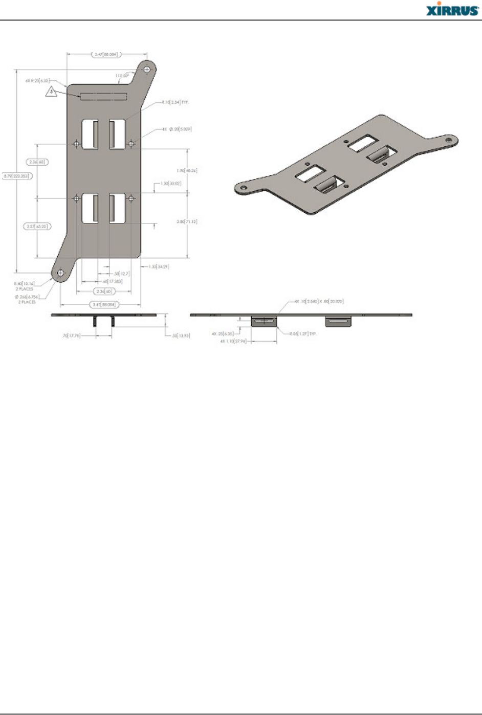
Drawings
XR520H Dimensions
- 11 -
XR5 2 0 H Qu ick I nst a llat ion Guide
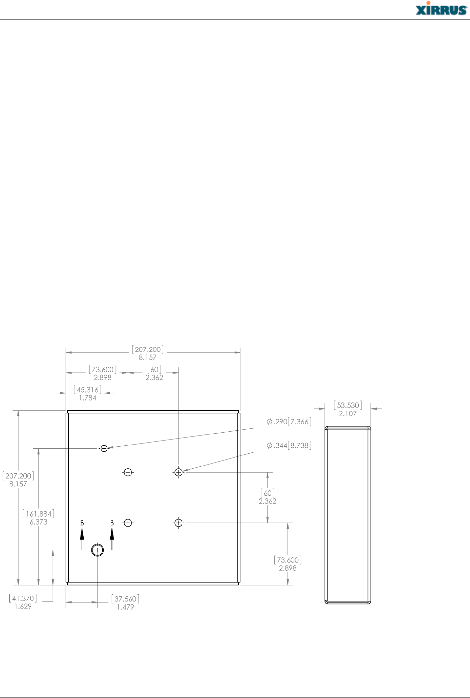
Mounting Bracket Dimensions xxxx
Customer Support
Xirrus Customer Service Representatives are available 24 x 7 via:
Email: support@xirrus.com
Chat: (Available Mon-Fri 12AM-12AM PST)
Phone:
United States and Canada: +1.800.947.7871 (US Toll Free) or +1.805.262.1600 (Direct)
Europe, Middle East, and Africa: +44.20.3239.8644
Australia: 1 300 XIRRUS (1300 947 787 - Local Call Cost)
Asia and Oceania: +61.2.8006.0622
Latin, Central, and South America: +1.805.262.1600
Notices, Warnings, & Compliance Statements
Notices
Read all user documentation before powering this device. Please verify the integrity of the
system ground prior to installing Xirrus equipment. Additionally, verify that the ambient
operating temperature does not exceed 65°C.
- 12 -

XR5 2 0 H Qu ick I nst a llat ion Guide
Software used by the modular Access Points (APs) is covered by the Xirrus Software License
and Product Warranty Agreement.
Non-Modification Statement: Unauthorized changes or modifications to the device are not
permitted. Use only Xirrus-approved external antennas supplied or recommended by the
manufacturer. Modifications to the device will void the warranty and may violate FCC
regulations.
UL Statement: Use only with listed ITE product.
Operating Frequency: The operating frequency in a wireless LAN is determined by the
access point. It is important that the access point is correctly configured to meet the local
regulations. If you have questions regarding the compliance of Xirrus products, please
contact us at: Xirrus, Inc., 2101 Corporate Center Drive, Thousand Oaks, CA 91320, USA.
Tel: 1.805.262.1600/1.800.947.7871 Toll Free in the US, Fax: 1.866.462.3980, www.xirrus.com
The 2-GHz b/g/n radio operates in 2.4 GHz ISM band. It supports channels 1-11 in US, 1-13
in Europe, and 1-13 in Japan. It has two transmitters with a maximum total output power of
25dBm for 802.11b/g/n operation. Output power is configurable to 5 levels. It has three
receivers that enables maximum-ratio combining (MRC).
The 5-GHz a/n radio operates in the UNII-2 band (5.25 - 5.35 GHz), UNII-2 Extended/ETSI
band (5.47 - 5.725 GHz), and the upper ISM band (5.725 - 5.850 GHz). It has two transmitters
with a maximum total output power of 26 dBm for UNII-2 and Extended/ETSI bands for the
A-domain. The total maximum output power for the upper ISM band is 28 dBm for A-
domain. Power settings will change depending on the regulatory domain
High power radars are allocated as primary users (meaning they have priority) in the
5250MHz to 5350MHz and 5650MHz to 5850MHz bands. These radars could cause
interference and/or damage Wireless LAN devices.
Calculating the Maximum Output Power: The regulatory limits for maximum output power
are specified in EIRP (equivalent isotropic radiated power). The EIRP level of a device can
be calculated by adding the gain of the antenna used (specified in dBi) to the output power
available at the connector (specified in dBm).
The FCC limits the amount of power this device can transmit. Power transmitted is a
combination of the amplification of the signal and the antenna gain. This device has been
designed to operate with antennas having an effective maximum gain of 9dBi in the 2.4 GHz
band and 6 dBi in the 5 GHz band. Antennas having a gain greater than this are strictly
prohibited for use with this device. The required antenna impedance is 50 ohms. Effective
maximum gain is antenna gain minus cable loss.
- 13 -

XR5 2 0 H Qu ick I nst a llat ion Guide
Warnings
GENERAL SAFETY GUIDELINES
WARNING: This warning symbol means danger. You are in a situation that could
cause bodily injury. Before you work on any equipment, be aware of the hazards
involved with electrical circuitry and be familiar with standard practices for
preventing accidents.
WARNING: Only trained and qualified personnel should be allowed to install,
replace, or service this equipment.
WARNING: Ultimate disposal of this product should be handled according to all
national laws and regulations.
WARNING: Incorrect installation of Xirrus Access Points may invalidate FCC, CE
mark, or other regulatory compliance approvals. Customers are responsible for any
legal violations from operation of un-approved equipment or incorrect installation.
WARNING: Do not operate the Access Point near unshielded blasting caps or in an
explosive environment unless the device has been modified to be especially qualified
for such use.
CAUTION: The liquid-tight adapters must be used on all input/output connections to
the Access Point where the installation is a non-hazardous location (and conduit is not
used).
POWER
WARNING: Read the installation instructions before connecting the system to the
power source.
WARNING: Installation of the equipment must comply with local and national
electrical codes.
WARNING: This equipment must be externally grounded using a customer-supplied
ground wire before power is applied. Contact the appropriate electrical inspection
authority or an electrician if you are uncertain that suitable grounding is available.
WARNING: Do not work on the system or connect or disconnect cables during periods
of lightning activity.
WARNING: To reduce the risk of fire, use only No. 26 AWG or larger
telecommunication line cord.
CAUTION: When the Access Point is installed outdoors or in a wet or damp location,
the AC branch circuit that is powering the Injector should be provided with ground
fault protection (GFCI), as required by Article 210 of the National Electrical Code
(NEC).
- 14 -
XR5 2 0 H Qu ick I nst a llat ion Guide
CAUTION: Xirrus PoGE Injectors rely on the building’s installation for over current
protection. Ensure that a fuse or circuit breaker no larger than 120 VAC, 15A (U.S.) or
240 VAC, 10A (International) is used on all current-carrying conductors.
EXTERNAL ANTENNAS
WARNING: In order to comply with radio frequency (RF) exposure limits, the
antennas for this product should be positioned no less than 23.2 cm from your body or
nearby persons.
WARNING: Do not locate the antenna near overhead power lines or other electric
light or power circuits, or where it can come into contact with such circuits. When
installing the antenna, take extreme care not to come into contact with such circuits,
because they may cause serious injury or death. For proper installation and grounding
of the antenna, please refer to national and local codes (for example, U.S.:NFPA 70,
National Electrical Code, Article 810, Canada: Canadian Electrical Code, Section 54).
This device has been designed to operate with antennas having an effective maximum
gain of 9dBi in the 2.4 GHz band and 6 dBi in the 5 GHz band. Antennas having a gain
greater than this are strictly prohibited for use with this device. The required antenna
impedance is 50 ohms. Effective maximum gain is antenna gain minus cable loss.
To reduce potential radio interference to other users, the antenna type and its gain
should be so chosen that the equivalent isotropically radiated power (EIRP) is not
more than that permitted for successful communication.
Wi-Fi Alliance Certification
Federal Communications Commission (FCC) Statements & Instructions
FCC Declaration of Conformity Statement
This device complies with Part 15 of the FCC Rules, with operation subject to the following two
conditions: (1) This device may not cause harmful interference, and (2) this device must accept
any interference received, including interference that may cause unwanted operation. This
equipment has been tested and found to comply with the limits for a Class A digital device,
pursuant to Part 15 of the FCC rules. These limits are designed to provide reasonable protection
against harmful interference in a residential installation. This equipment generates, uses and
can radiate RF energy and, if not installed and used in accordance with the instructions, may
cause harmful interference to radio communications. However, there is no guarantee that
interference will not occur in a particular installation. If this equipment does cause harmful
- 15 -
This device complies with Part 15 of the FCC Rules. Operation is subject to the following two
conditions: (1) This device may not cause harmful interference, and (2) this device must accept
any interference received, including interference that may cause undesired operation.
This equipment has been tested and found to comply with the limits for a Class B digital device,
pursuant to Part 15 of the FCC Rules. These limits are designed to provide reasonable protection
against harmful interference in a residential installation. This equipment generates, uses and can
radiate radio frequency energy and, if not installed and used in accordance with the instructions,
may cause harmful interference to radio communications. However, there is no guarantee that
interference will not occur in a particular installation. If this equipment does cause harmful
interference to radio or television reception, which can be determined by turning the equipment off
and on, the user is encouraged to try to correct the interference by one of the following measures:
26

XR5 2 0 H Qu ick I nst a llat ion Guide
interference to radio or television reception, which can be determined by turning the equipment
off and on, the user is encouraged to try to correct the interference by one or more of the
following safety measures:
Reorient or relocate the receiving antenna.
Increase the separation between the equipment and the receiver.
Connect the equipment into an outlet on a circuit different from that to which the receiver is
connected.
FCC Caution: Any changes or modifications not expressly approved by the party responsible
for compliance could void the user's authority to operate this equipment.
Consult the dealer or an experienced wireless technician for help. Use of a shielded twisted pair
(STP) cable must be used for all Ethernet connections in order to comply with EMC
requirements.
FCC-Specific Instructions (DFS band-master device is for future option)
The FCC, National Telecommunications and Information Administration (NTIA), Federal
Aviation Administration (FAA), and industry are working to resolve interference to Terminal
Doppler Weather Radar (TDWR) systems used near airports that has occurred from some
outdoor wireless systems operating in the 5470 MHz – 5725 MHz band. These wireless devices
are subject to Section 15.407 of our rules and while operating as a master device they are
required to implement radar detection and Dynamic Frequency Selection (DFS) functions.
Devices must be professionally installed when operating in the 5470 – 5725 MHz band
Any installation of either a master or a client device within 35 km of a TDWR location shall
be separated by at least 30 MHz (center-to-center) from the TDWR operating frequency (as
shown in the TDWR location at http://www.spectrumbridge.com/udia/home.aspx). This will
require that channel 116 is not used in these locations.
The installers and the operators must register the devices in the industry-sponsored
database with the appropriate information regarding the location and operation of the
device and installer information. A voluntary Wireless Internet Service
Providers Association (WISPA) sponsored database has been developed that allows
operators and installers to register the location information of the Unlicensed National
Information Infrastructure (UNII) devices operating outdoors in the 5470 – 5725 MHz band
within 35 km of any TDWR location (see http://www.spectrumbridge.com/udia/home.aspx).
This database may be used by government agencies to expedite resolution of any
interference to TDWRs.
FCC Safety Compliance Statement
The FCC with its action in ET Docket 96-8 has adopted a safety standard for human exposure to
radio frequency (RF) electromagnetic energy emitted by FCC certified equipment. When used
with approved Xirrus antennas, Xirrus XR products meet the uncontrolled environmental limits
- 16 -
- Reorient or relocate the receiving antenna.
- Increase the separation between the equipment and receiver.
- Connect the equipment into an outlet on a circuit different from that to which the receiver is
connected.
- Consult the dealer or an experienced radio/TV technician for help.
FCC Caution: Any changes or modifications not expressly approved by the party responsible for
compliance could void the user's authority to operate this equipment.
This transmitter must not be co-located or operating in conjunction with any other antenna or
transmitter.
Operations in the 5.15-5.25GHz band are restricted to indoor usage only.
Radiation Exposure Statement:
This equipment complies with FCC radiation exposure limits set forth for an uncontrolled
environment. This equipment should be installed and operated with minimum distance 26cm
between the radiator & your body.

XR5 2 0 H Qu ick I nst a llat ion Guide
found in OET-65 and ANSI C95.1, 1991. Proper installation of this radio according to the
instructions found in this manual will result in user exposure that is substantially below the
FCC recommended limits.
Industry Canada Statements and Warnings
Industry Canada Notice and Marking: This Class A digital apparatus complies with Canadian
ICES-003.
Cet appareil numérique de la classe A est conforme à la norme NMB-003 du Canada.
The term “IC:” before the radio certification number only signifies that Industry Canada
technical specifications were met.
Under Industry Canada regulations, this radio transmitter may only operate using an antenna
of a type and maximum (or lesser) gain approved for the transmitter by Industry Canada. To
reduce potential radio interference to other users, the antenna type and its gain should be so
chosen that the equivalent isotropically radiated power (e.i.r.p.) is not more than that necessary
for successful communication.
Conformément à la réglementation d'Industrie Canada, le présent émetteur radio peut fonctionner avec
une antenne d'un type et d'un gain maximal (ou inférieur) approuvé pour l'émetteur par Industrie
Canada. Dans le but de réduire les risques de brouillage radioélectrique à l'intention des autres
utilisateurs, il faut choisir le type d'antenne et son gain de sorte que la puissance isotrope rayonnée
équivalente (p.i.r.e.) ne dépasse pas l'intensité nécessaire à l'établissement d'une communication
satisfaisante.
This device complies with Industry Canada license-exempt RSS standard(s). Operation is
subject to the following two conditions: (1) this device may not cause interference, and (2) this
device must accept any interference, including interference that may cause undesired operation
of the device.
Le présent appareil est conforme aux CNR d'Industrie Canada applicables aux appareils radio exempts de
licence. L'exploitation est autorisée aux deux conditions suivantes: (1) l'appareil ne doit pas produire de
brouillage, et (2) l'utilisateur de l'appareil doit accepter tout brouillage radioélectrique subi, même si le
brouillage est susceptible d'en compromettre le fonctionnement.
Xirrus Access Points are certified to the requirements of RSS-210. The use of this device in a
system operating either partially or completely outdoors may require the user to obtain a
license for the system according to the Canadian regulations. For further information, contact
your local Industry Canada office.
RF Radiation Hazard Warning: To ensure compliance with FCC and Industry Canada RF
exposure requirements, this device must be installed in a location where the antennas of the
device will have a minimum distance of at least 23.2 cm from all persons. Using higher gain
antennas and types of antennas not certified for use with this product is not allowed. The device
shall not be co-located with another transmitter.
- 17 -
Class B
Class B
26
Radiation Exposure Statement:
This equipment complies with IC radiation exposure limits set forth for an uncontrolled
environment. This equipment should be installed and operated with minimum distance 26cm
between the radiator & your body.
Déclaration d'exposition aux radiations:
Cet équipement est conforme aux limites d'exposition aux rayonnements IC établies pour un
environnement non contrôlé. Cet équipement doit être installé et utilisé avec un minimum de 26
cm de distance entre la source de rayonnement et votre corps.

XR5 2 0 H Qu ick I nst a llat ion Guide
Installez l'appareil en veillant à conserver une distance d'au moins 23.2 cm entre les éléments
rayonnants et les personnes. Cet avertissement de sécurité est conforme aux limites d'exposition
définies par la norme CNR-102 at relative aux fréquences radio.
High Power Radars: High power radars are allocated as primary users (meaning they have
priority) in the 5250MHz to 5350MHz and 5650MHz to 5850MHz bands. These radars could
cause interference and/or damage to Wireless LAN devices used in Canada.
Les utilisateurs de radars de haute puissance sont désignés utilisateurs principaux (c.-à-
d., qu’ils ont la priorité) pour les bandes 5 250 - 5 350 MHz et 5 650 - 5 850 MHz. Ces
radars pourraient causer du brouillage et/ou des dommages aux dispositifs LAN-EL.
EU Directive 1999/5/EC Compliance Information
This section contains compliance information for the Xirrus Wireless Access Point
family of products. The compliance information contained in this section is relevant to
the European Union and other countries that have implemented the EU Directive
1999/5/EC.
This declaration is only valid for configurations (combinations of software, firmware and
hardware) provided and/or supported by Xirrus Inc. The use of software or firmware not
supported/provided by Xirrus Inc. may result that the equipment is no longer compliant with
the regulatory requirements.
Declaration of Conformity
Cesky [Czech] Toto zahzeni je v souladu se základnimi požadavky a ostatnimi odpovidajcimi
ustano veni mi Směrnice 1999/5/EC.
Dansk [Danish] Dette udstyr er i overensstemmelse med de væsentlige krav og andre relevante
bestemmelser i Direktiv 1999/5/EF.
Deutsch [German] Dieses Gerat entspricht den grundlegenden Anforderungen und den
weiteren entsprechenden Vorgaben der Richtinie 1999/5/EU.
Eesti [Estonian] See seande vastab direktiivi 1999/5/EU olulistele nöuetele ja teistele as
jakohastele sätetele.
English This equipment is in compliance with the essential requirements and other relevant
provisions of Directive 1999/5/EC.
Español [Spain] Este equipo cump le con los requisitos esenciales asi como con otras
disposiciones de la Directiva 1999/5/ CE.
Ελληνυκη [Greek] Αυτόζ ο εξοπλτσμόζ είναι σε συμμόρφωση με τιζ ουσιώδειζ απαιτήσειζ
και ύλλεζ σχετικέζ διατάξειζ τηζ Οδηγιαζ 1999/5/EC.
Français [French] Cet appareil est conforme aux exigences essentielles et aux autres dispositions
pertinentes de la Directive 1999/5/EC.
ĺslenska [Icelandic] Þetta tæki er samkvæmt grunnkröfum og öðrum viðeigandi ákvæðum
Tilskipunar 1999/5/EC.
- 18 -
26
Caution : (i) the device for operation in the band 5150-5250 MHz is only for indoor use to reduce the
potential for harmful interference to co-channel mobile satellite systems;
(ii) high-power radars are allocated as primary users (i.e. priority users) of the bands 5250-5350 MHz
and 5650-5850 MHz and that these radars could cause interference and/or damage to LE-LAN devices.
Avertissement:(i) les dispositifs fonctionnant dans la bande 5 150-5 250 MHz sont réservés
uniquement pour une utilisation à l'intérieur afin de réduire les risques de brouillage préjudiciable aux
systèmes de satellites mobiles utilisant les mêmes canaux;
(ii) De plus, les utilisateurs devraient aussi être avisés que les utilisateurs de radars de haute puissance
sont désignés utilisateurs principaux (c.-à-d., qu'ils ont la priorité) pour les bandes 5 250-5 350 MHz et
5 650-5 850 MHz et que ces radars pourraient causer du brouillage et/ou des dommages aux dispositifs
LAN-EL.

XR5 2 0 H Qu ick I nst a llat ion Guide
Italiano [Italian] Questo apparato é conforme ai requisiti essenziali ed agli altri principi sanciti
dalla Direttiva 1999/5/CE.
Latviski [Latvian] Šī iekārta atbilst Direktīvas 1999/5/EK būtiskajā prasībām un citiem ar to
saistītajiem noteikumiem.
Lietuvių [Lithuanian] Šis įrenginys tenkina 1995/5/EB Direktyvos esminius reikalavimus ir
kitas šios direktyvos nuostatas.
Nederlands [Dutch] Dit apparant voldoet aan de essentiele eisen en andere van toepassing
zijnde bepalingen van de Richtlijn 1995/5/EC.
Malti [Maltese] Dan l-apparant huwa konformi mal-htigiet essenzjali u l-provedimenti l-ohra
rilevanti tad-Direttiva 1999/5/EC.
Margyar [Hungarian] Ez a készülék teljesiti az alapvetö követelményeket és más 1999/5/EK
irányelvben meghatározott vonatkozó rendelkezéseket.
Norsk [Norwegian] Dette utstyret er i samsvar med de grunnleggende krav og andre relevante
bestemmelser i EU-direktiv 1999/5/EF.
Polski [Polish] Urządzenie jest zgodne z ogólnymi wymaganiami oraz sczególnymi mi
warunkami określony mi Dyrektywą. UE:1999/5/EC.
Portuguès [Portuguese] Este equipamento está em conformidade com os requisitos essenciais e
outras provisões relevantes da Directiva 1999/5/EC.
Slovensko [Slovenian] Ta naprava je skladna z bistvenimi zahtevami in ostalimi relevantnimi
popoji Direktive 1999/5/EC.
Slovensky [Slovak] Toto zariadenie je v zhode so základnými požadavkami a inými
prislušnými nariadeniami direktiv: 1999/5/EC.
Suomi [Finnish] Tämä laite täyttää direktiivin 1999/5//EY olennaiset vaatimukset ja on siinä
asetettujen muiden laitetta koskevien määräysten mukainen.
Svenska [Swedish] Denna utrustning är i överensstämmelse med de väsentliga kraven och
andra relevanta bestämmelser i Direktiv 1999/5/EC.
Assessment Criteria: The following standards were applied during the assessment of the
product against the requirements of the Directive 1999/5/EC:
Radio: EN 301 893 and EN 300 328 (if applicable)
EMC: EN 301 489-1 and EN 301 489-17
Safety: EN 50371 to EN 50385 and EN 60601
CE Marking: For the Xirrus Wireless Access Point, the CE mark and Class-2 identifier opposite
are affixed to the equipment and its packaging:
- 19 -
XR5 2 0 H Qu ick I nst a llat ion Guide
WEEE Compliance: Natural resources were used in the production of this equipment.
This equipment may contain hazardous substances that could impact the
health of the environment.
If you need more information on collection, re-use and recycling systems,
please contact your local or regional waste administration.
Please contact Xirrus for specific information on the environmental
performance of our products.
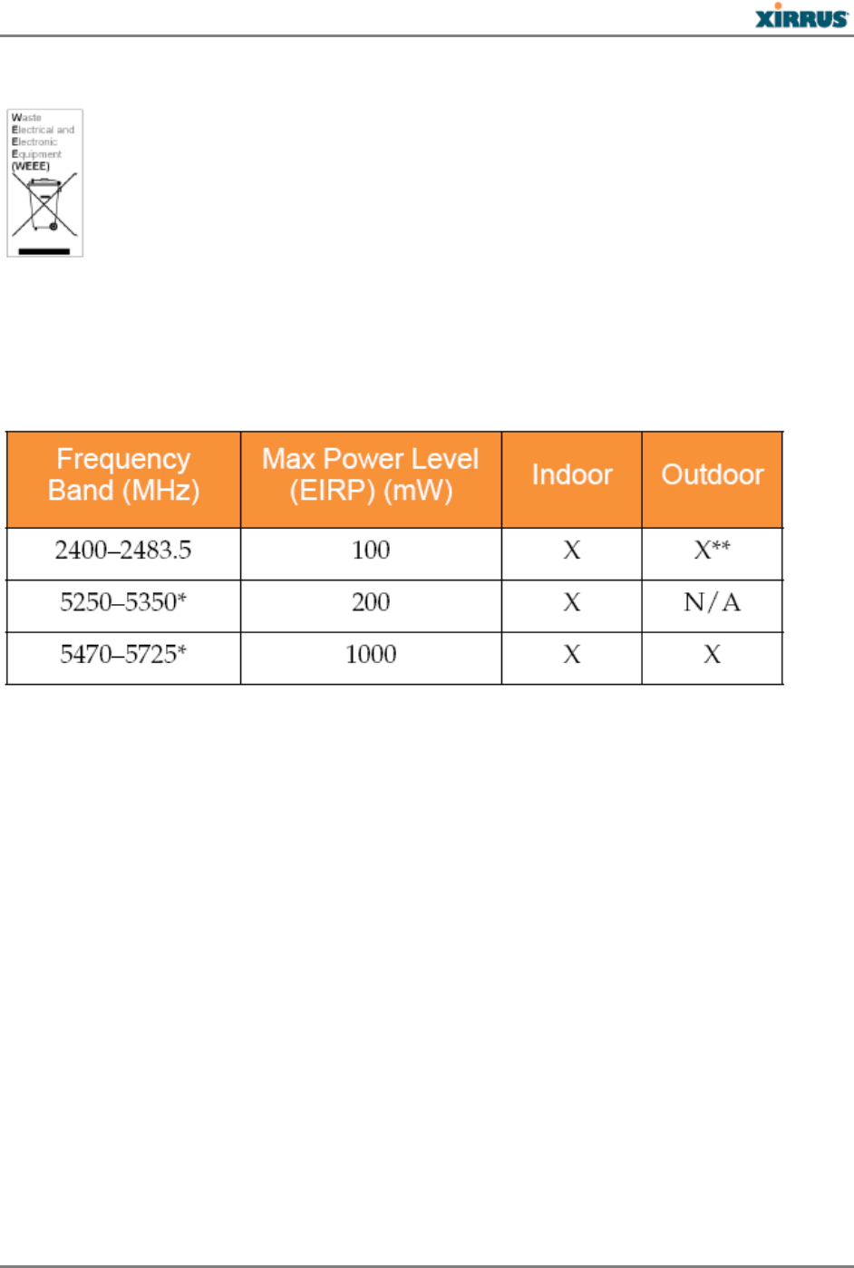
National Restrictions: In the majority of the EU and other European countries, the 2.4 GHz and
5 GHz bands have been made available for the use of Wireless LANs. The following table
provides an overview of the regulatory requirements in general that are applicable for the 2.4
GHz and 5 GHz bands.
*Dynamic frequency selection and Transmit Power Control is required in these frequency bands.
**France is indoor use only in the upper end of the band.
The requirements for any country may change at any time. Xirrus recommends that you check
with local authorities for the current status of their national regulations for both 2.4 GHz and 5
GHz wireless LANs. The following countries have additional requirements or restrictions than
those listed in the above table:
Belgium: The Belgian Institute for Postal Services and Telecommunications (BIPT) must be
notified of any outdoor wireless link having a range exceeding 300 meters. Xirrus recommends
checking at www.bipt.be for more details.
Draadloze verbindingen voor buitengebruik en met een reikwijdte van meer dan 300 meter dienen
aangemeld te worden bij het Belgisch Instituut voor postdiensten en telecommunicatie (BIPT). Zie
www.bipt.be voor meer gegevens.
Les liasons sans fil pour une utilisation en extérieur d’une distance supérieure à 300 mèters doivent être
notifiées à l’Institut Belge des services Postaux et des Télécommunications (IBPT). Visitez www.bipt.be
pour de plus amples détails.
Greece: A license from EETT is required for the outdoor operation in the 5470 MHz to 5725
MHz band. Xirrus recommends checking www.eett.gr for more details.
- 20 -

XR5 2 0 H Qu ick I nst a llat ion Guide
Η δη ιουργβάικτ ωνεξωτερικο ρουστη ζ νησυ νοτ των 5470–5725 ΜΗz ε ιτρ ετάιωνο ετάά
όάδειά της ΕΕΤΤ, ου ορηγεβτάι στερά ά ό σ φωνη γν η του ΓΕΕΘΑ. Ερισσότερες λε τομ
ρειεωστο www.eett.gr
Italy: This product meets the National Radio Interface and the requirements specified in the
National Frequency Allocation Table for Italy. Unless this wireless LAN product is operating
within the boundaries of the owner’s property, its use requires a “general authorization.” Please
check with www.communicazioni.it/it/ for more details.
Questo prodotto é conforme alla specifiche di Interfaccia Radio Nazionali e rispetta il Piano Nazionale di
ripartizione delle frequenze in Italia. Se non viene installato all’interno del proprio fondo, l’utilizzo di
prodotti wireless LAN richiede una “autorizzazione Generale.” Consultare www.communicazioni.it/it/
per maggiori dettagli.
Norway, Switzerland and Liechtenstein: Although Norway, Switzerland and Liechtenstein are
not EU member states, the EU Directive 1999/5/EC has also been implemented in those
countries.
RF Exposure
Generic Information
The Xirrus Access Point products are designed to comply with the following national and
international standards on Human Exposure to Radio Frequencies:
US 47 Code of Federal Regulations Part 2 Subpart J
American National Standards Institute (ANSI) / Institute of Electrical and Electronic
Engineers / IEEE C 95.1 (99)
International Commission on Non Ionizing Radiation Protection (ICNIRP) 98
Ministry of Health (Canada) Safety Code 6. Limits on Human Exposure to Radio Frequency
Fields in the range from 3kHz to 300 GHz
Australia Radiation Protection Standard
To ensure compliance with various national and international Electromagnetic Field (EMF)
standards, the system should only be operated with Xirrus approved antennas and accessories.
Declaration on Conformity
This access point product has been found to be compliant to the requirements set forth in CFR
47 Section 1.1307 addressing RF Exposure from radio frequency devices as defined in
Evaluating Compliance with FCC Guidelines for Human Exposure to Radio Frequency
Electromagnetic Fields.
Use is permitted with antennas having an effective maximum gain of 9 dBi in the 2.4 GHz band
and 6 dBi in the 5 GHz band. Antennas having a gain greater than this are strictly prohibited for
use with this device. The required antenna impedance is 50 ohms. Effective maximum gain is
- 21 -
XR5 2 0 H Qu ick I nst a llat ion Guide
antenna gain minus cable loss. A minimum separation distance of 23.2 cm between the antenna
and all persons is required during normal operation.
Only antennas provided by Xirrus for use with the product should be installed. The use of any
other antennas may cause damage to the access points or violate regulatory emission limits and
will not be supported by Xirrus.
International Guidelines for Exposure to Radio Waves
The Xirrus Access Points include radio transmitters and receivers. It is designed not to exceed
the limits for exposure to radio waves (radio frequency electromagnetic fields) recommended
by international guidelines. The guidelines were developed by an independent scientific
organization (ICNIRP) and include a substantial safety margin designed to ensure the safety of
all persons, regardless of age and health.
As such the systems are designed to be operated as to avoid contact with the antennas by the
end user. It is recommended to set the system in a location where the antennas can remain at
least a minimum distance as specified from the user in accordance to the regulatory guidelines
which are designed to reduce the overall exposure of the user or operator.
Separation Distance
MPE
Distance
Limit
1.34 mW/cm2
23.2 cm
1.00 mW/cm2
The World Health Organization has stated that present scientific information does not indicate
the need for any special precautions for the use of wireless devices. They recommend that if you
are interested in further reducing your exposure then you can easily do so by reorienting
antennas away from the user or placing the antennas at a greater separation distance then
recommended.
FCC Guidelines for Exposure to Radio Waves
The device includes a radio transmitter and receiver. It is designed not to exceed the limits for
exposure to radio waves (radio frequency electromagnetic fields) as referenced in FCC Part
1.1310. The guidelines are based on IEEE ANSI C 95.1 (92) and include a substantial safety
margin designed to ensure the safety of all persons, regardless of age and health.
As such the systems are designed to be operated as to avoid contact with the antennas by the
end user. It is recommended to set the system in a location where the antennas can remain at
least a minimum distance as specified from the user in accordance to the regulatory guidelines
which are designed to reduce the overall exposure of the user or operator.
Separation Distance
MPE
Distance
Limit
1.34 mW/cm2
23.2 cm
1.00 mW/cm2
The device has been tested and found compliant with the applicable regulations as part of the
radio certification process.
- 22 -
26
26
26
XR5 2 0 H Qu ick I nst a llat ion Guide
The US Food and Drug Administration has stated that present scientific information does not
indicate the need for any special precautions for the use of wireless devices. The FCC
recommends that if you are interested in further reducing your exposure then you can easily do
so by reorienting antennas away from the user or placing the antennas at a greater separation
distance then recommended or lowering the transmitter power output.
Industry Canada Guidelines for Exposure to Radio Waves
The Xirrus Access Points include radio transmitters and receivers. It is designed not to exceed
the limits for exposure to radio waves (radio frequency electromagnetic fields) as referenced in
Health Canada Safety Code 6. The guidelines include a substantial safety margin designed into
the limit to ensure the safety of all persons, regardless of age and health.
As such the systems are designed to be operated as to avoid contact with the antennas by the
end user. It is recommended to set the system in a location where the antennas can remain at
least a minimum distance as specified from the user in accordance to the regulatory guidelines
which are designed to reduce the overall exposure of the user or operator.
Separation Distance
MPE
Distance
Limit
1.34 mW/cm2
23.2 cm
1.00 mW/cm2
Health Canada states that present scientific information does not indicate the need for any
special precautions for the use of wireless devices. They recommend that if you are interested in
further reducing your exposure you can easily do so by reorienting antennas away from the
user, placing the antennas at a greater separation distance than recommended, or lowering the
transmitter power output.
Additional Information on RF Exposure
You can find additional information on the subject at the following links:
FCC Bulletin 56: Questions and Answers about Biological Effects and Potential Hazards of
Radio Frequency Electromagnetic Fields
FCC Bulletin 65: Evaluating Compliance with the FCC guidelines for Human Exposure to
Radio Frequency Electromagnetic Fields
FCC Bulletin 65C (01-01): Evaluating Compliance with the FCC guidelines for Human
Exposure to Radio Frequency Electromagnetic Fields: Additional Information for Evaluating
Compliance for Mobile and Portable Devices with FCC limits for Human Exposure to Radio
Frequency Emission
You can obtain additional information from the following organizations:
World Health Organization Internal Commission on Non-Ionizing Radiation Protection at
this URL: www.who.int/emf
United Kingdom, National Radiological Protection Board at this URL: www.nrpb.org.uk
- 23 -
26

XR5 2 0 H Qu ick I nst a llat ion Guide
Cellular Telecommunications Association at this URL: www.wow-com.com
The Mobile Manufacturers Forum at this URL: www.mmfai.org
- 24 -
XR5 2 0 H Qu ick I nst a llat ion Gu ide
1.800.947.7871 Toll Free in t he US
+ 1.805.262.1600 Sales
+ 1.805.262.1601 Fax
2101 Corporate Cent er Dr ive
Thousand Oaks, CA. 91320 USA
To learn mor e v isit :
xir r us.com or
em ail: info @ xirr us.com
812-0085-003B
2013 Xir r us I nc. All Right Reserv ed. This Xir rus logo is a regist ered t r adem ar k of Xirr us, I nc.
All other t radem arks are the property of their respect iv e owners. Content subj ect to change wit hout notice.