Cambium Networks XR620 802.11ac 2x2 AP User Manual Xirrus AOS Xirrus
Xirrus, Inc. 802.11ac 2x2 AP Xirrus AOS Xirrus
UserManual.wiki
>
Cambium Networks
>
XR620 User Manual
>
User Manual
Contents
1.
User Manual 1.pdf
2.
User Manual 2.pdf
3.
User manual 1
4.
User manual 2
5.
User manual (statement)
6.
User Manual
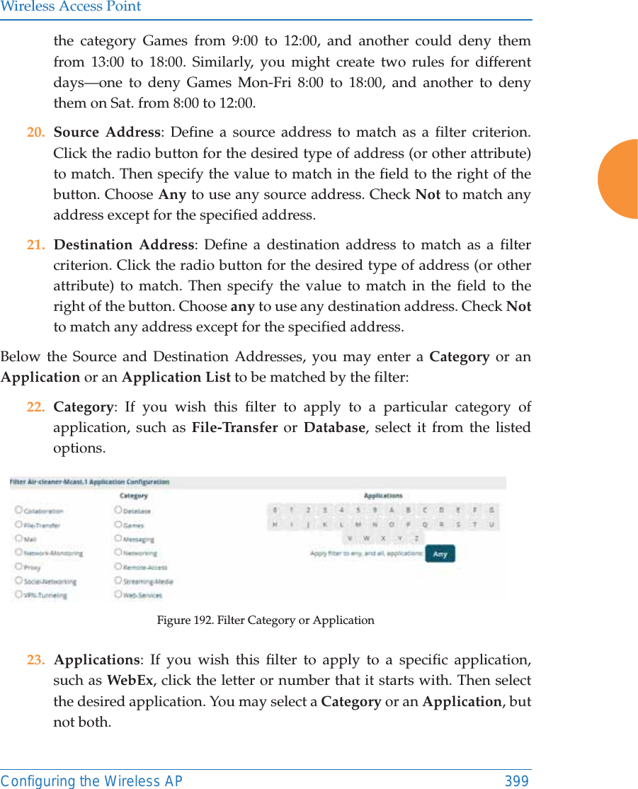
User Manual
Navigation menu
Upload a User Manual
Namespaces
Wiki Guide
HTML
PDF
Info
Views
User Manual
Discussion / Help
Navigation

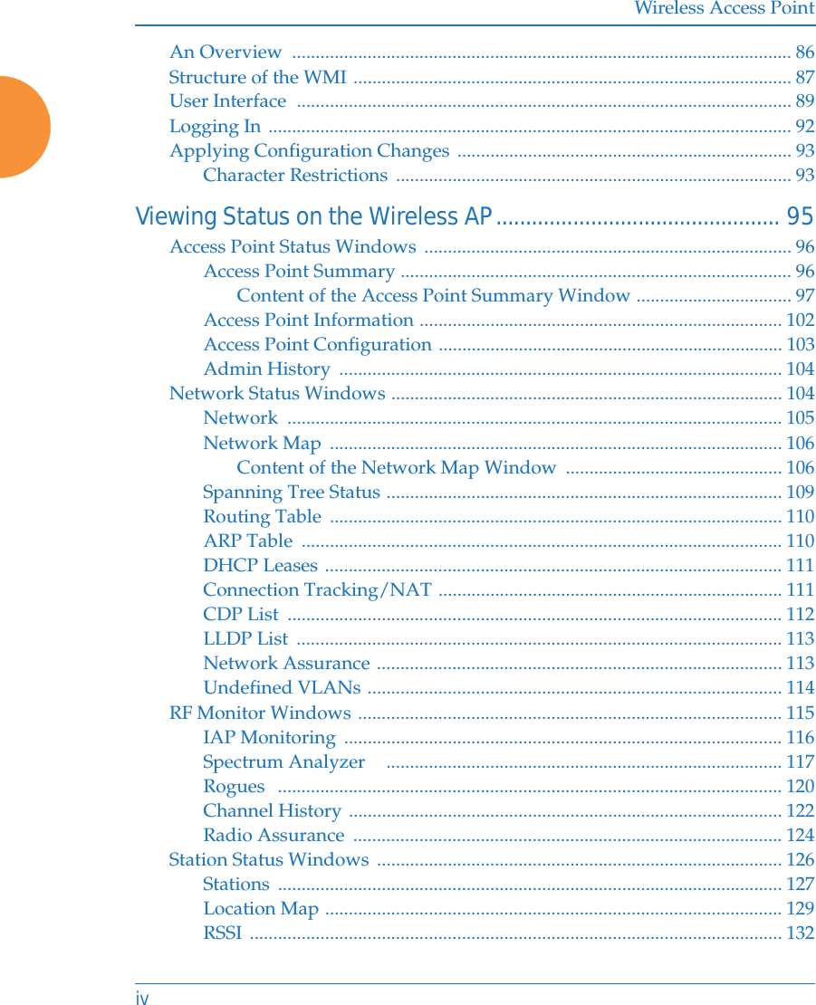

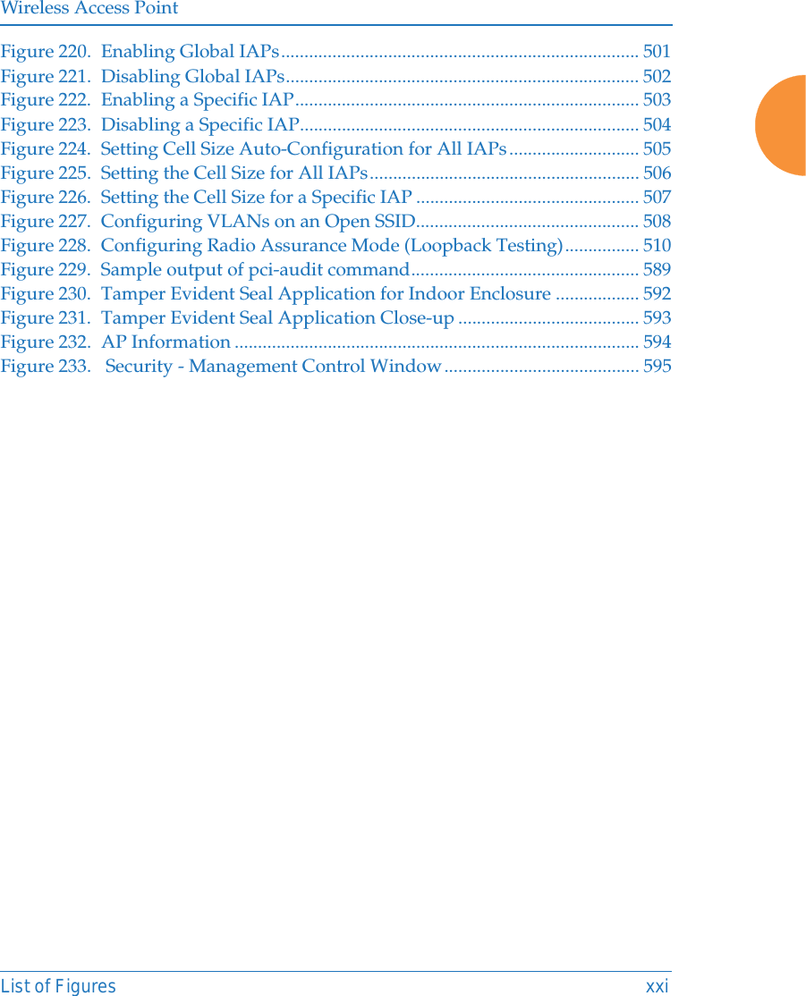

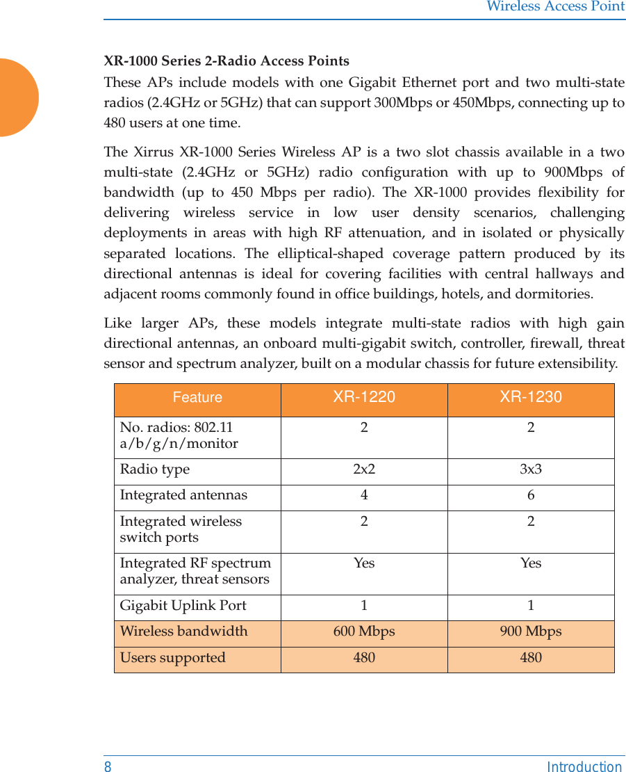

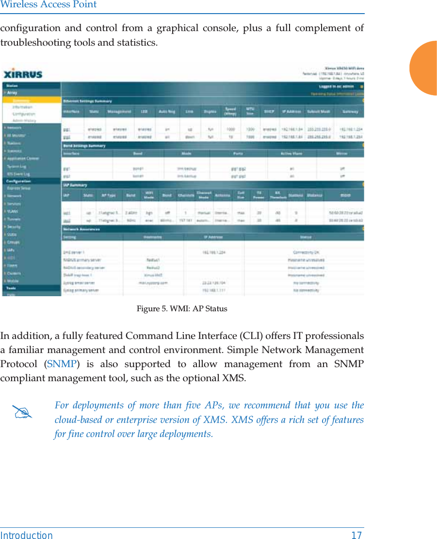
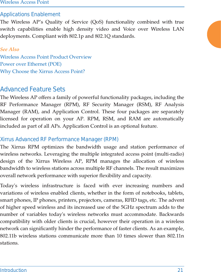
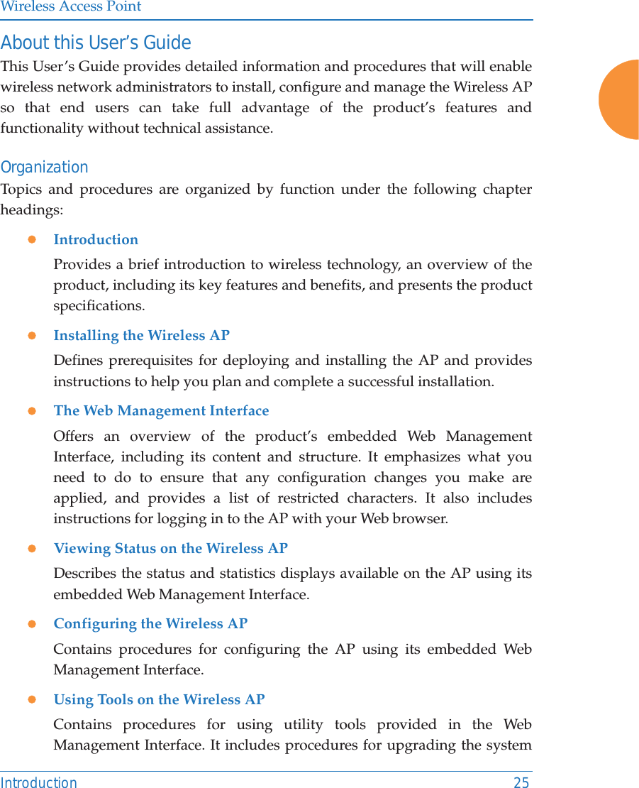

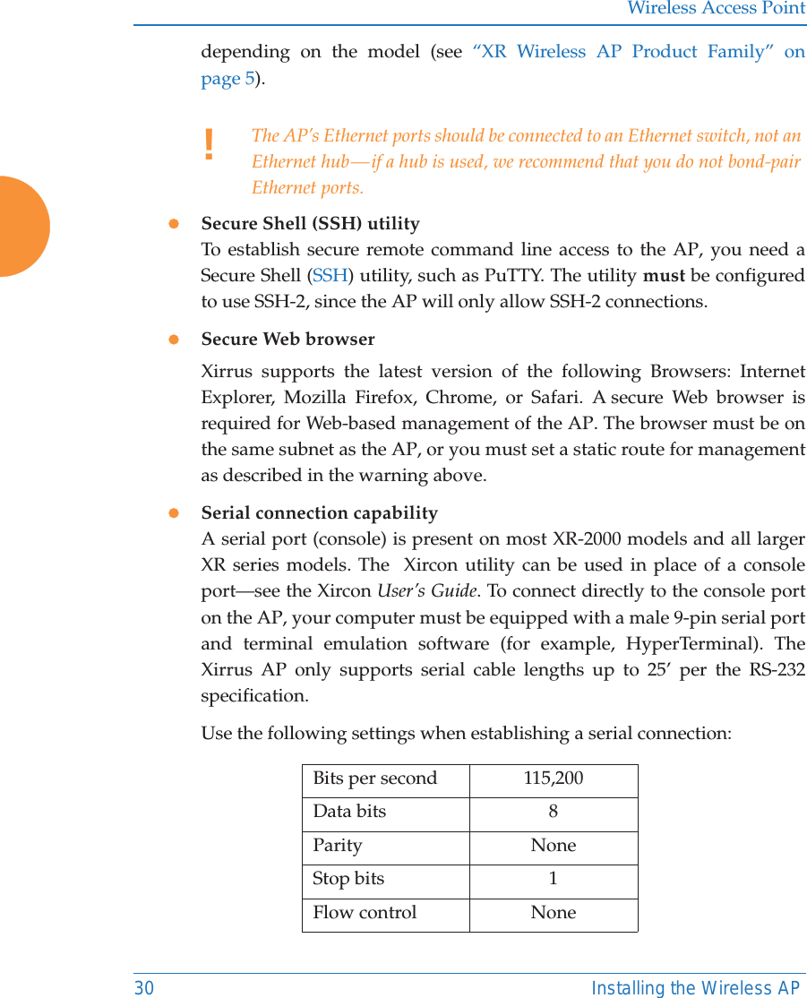
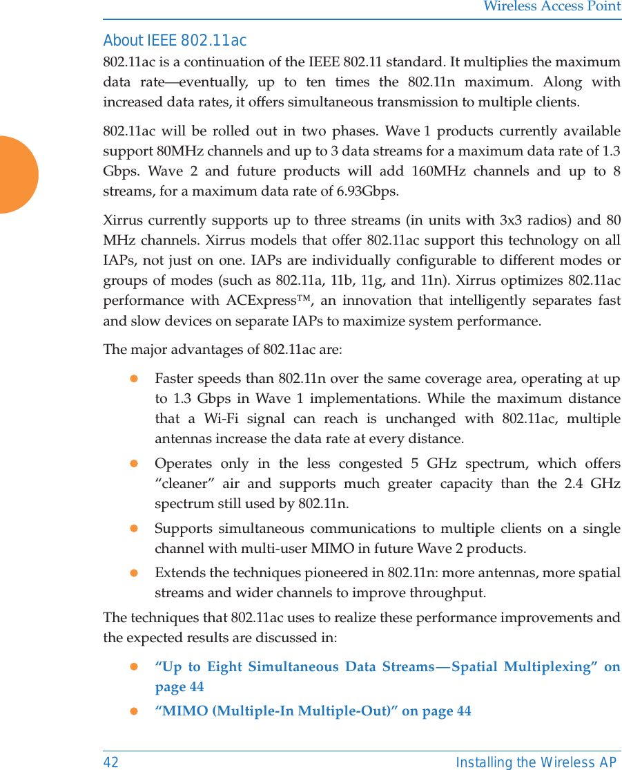
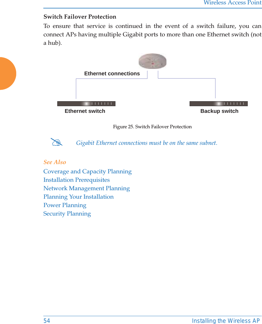
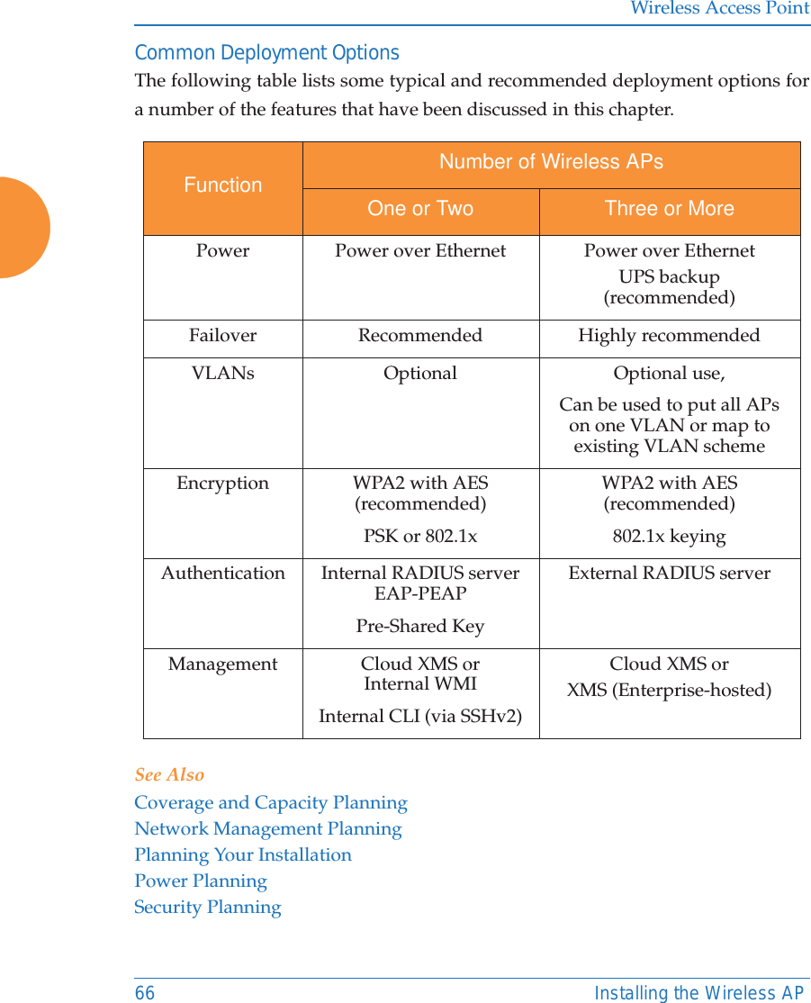
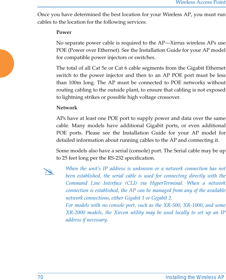

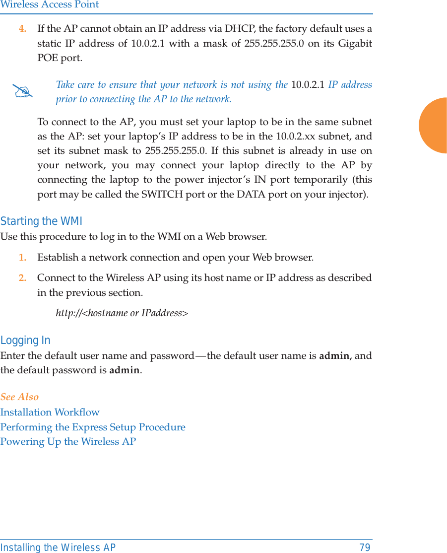

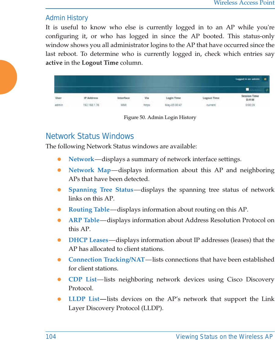
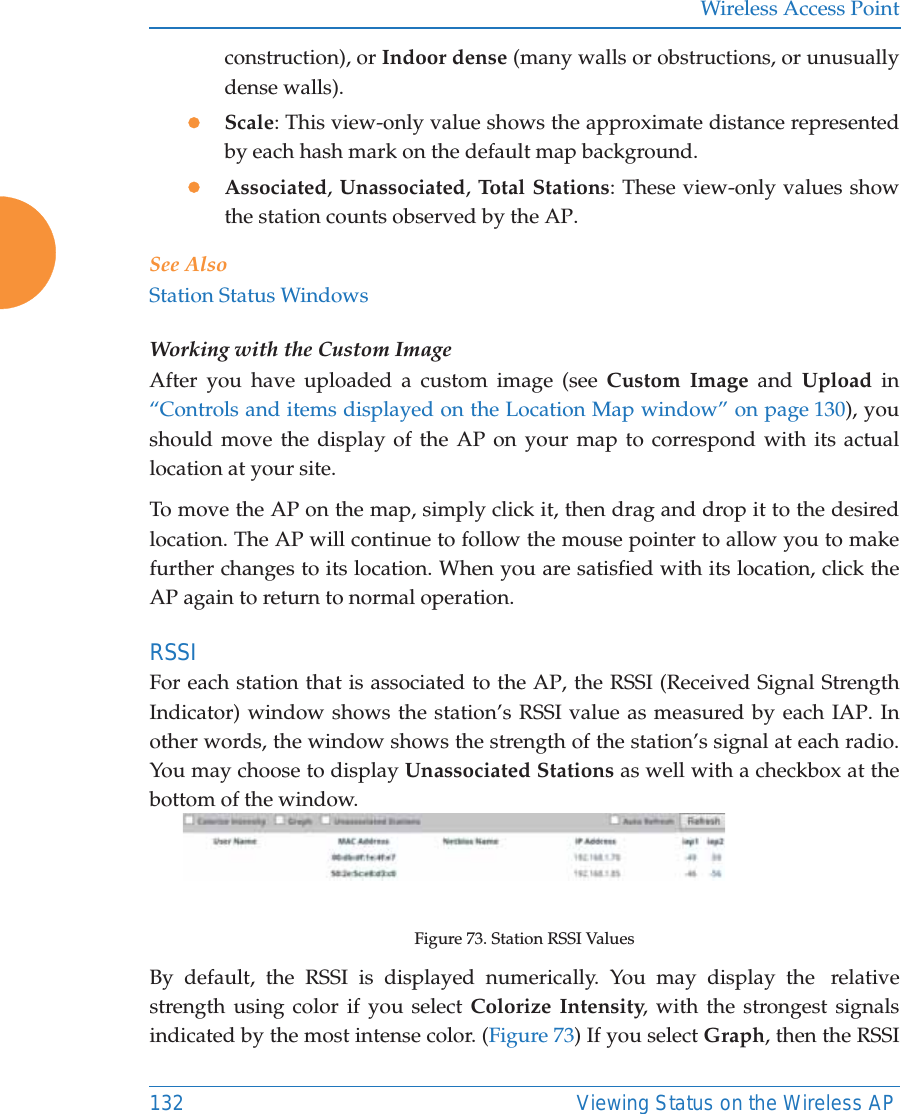
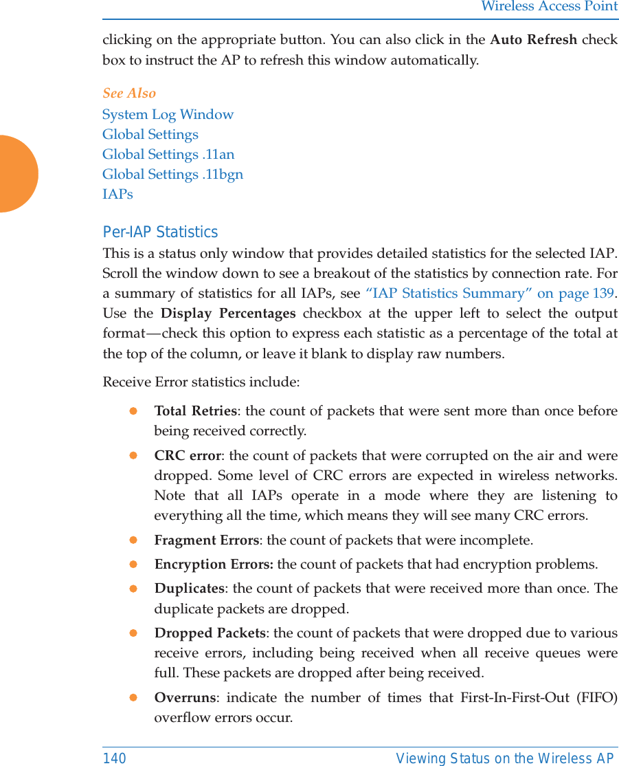
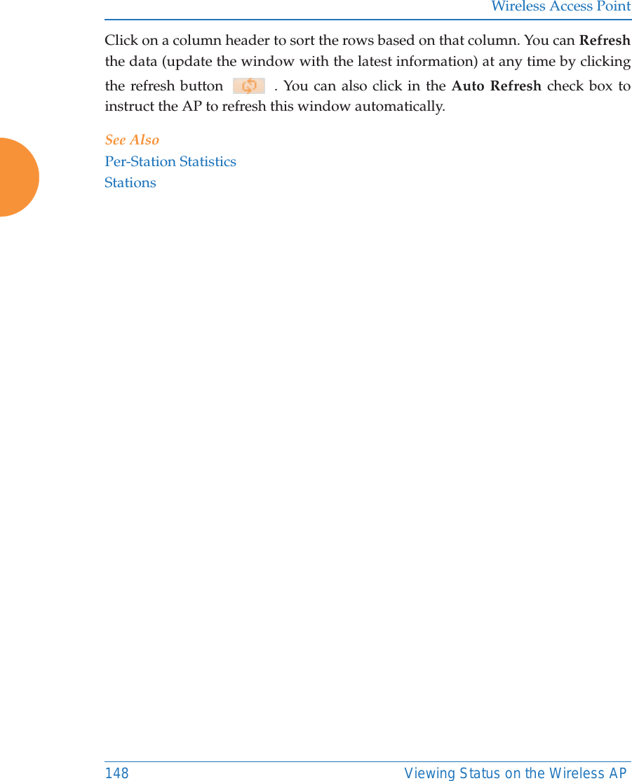

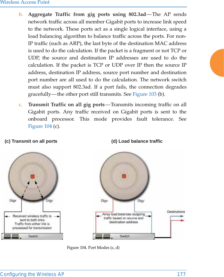
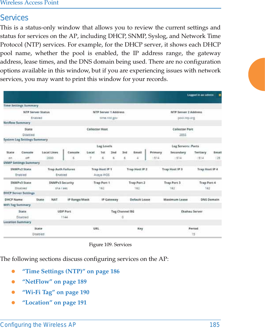

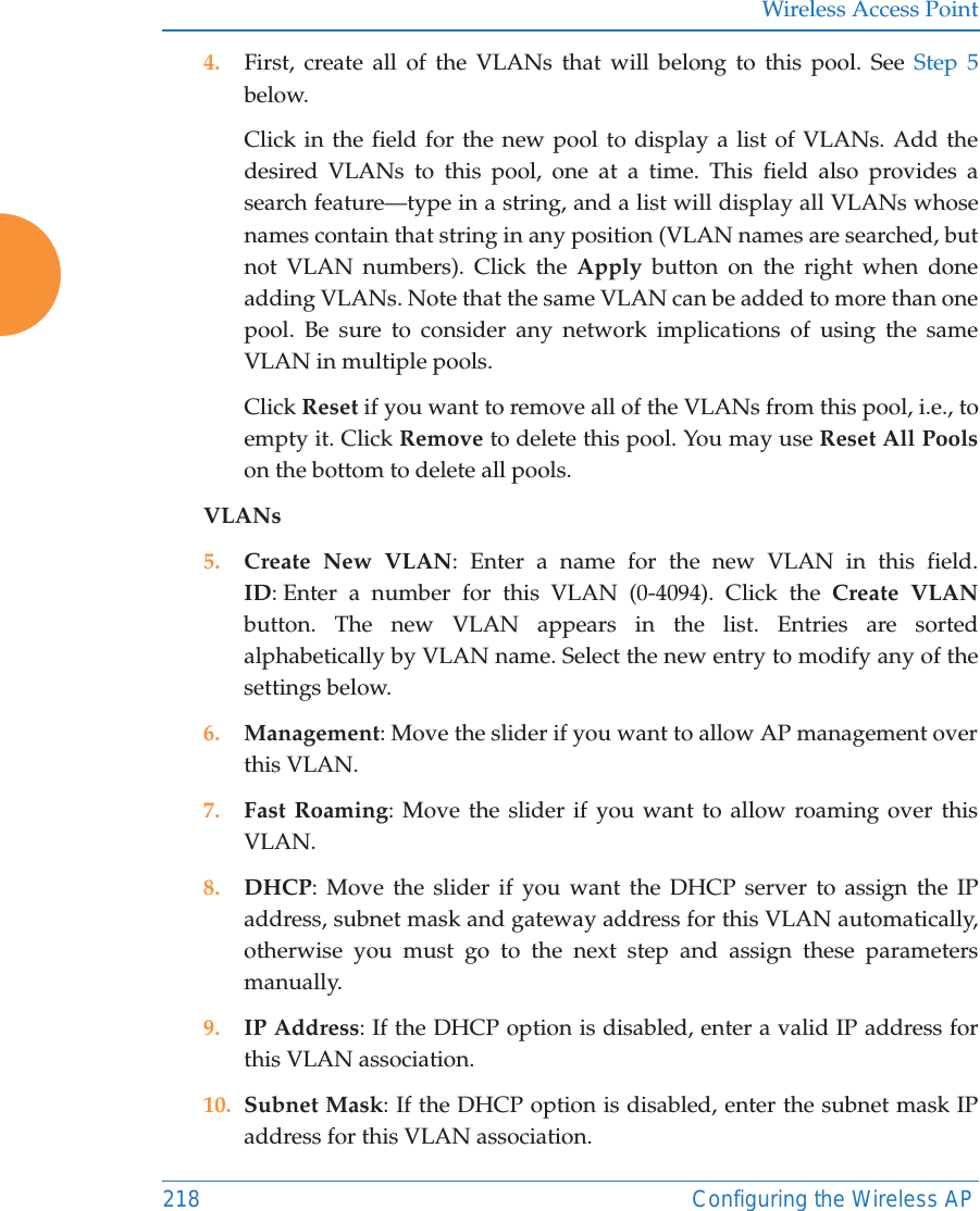
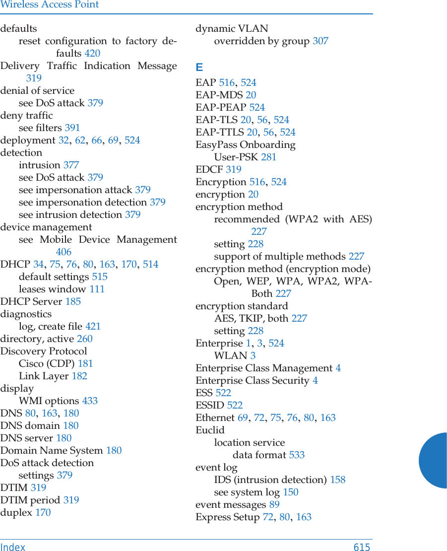
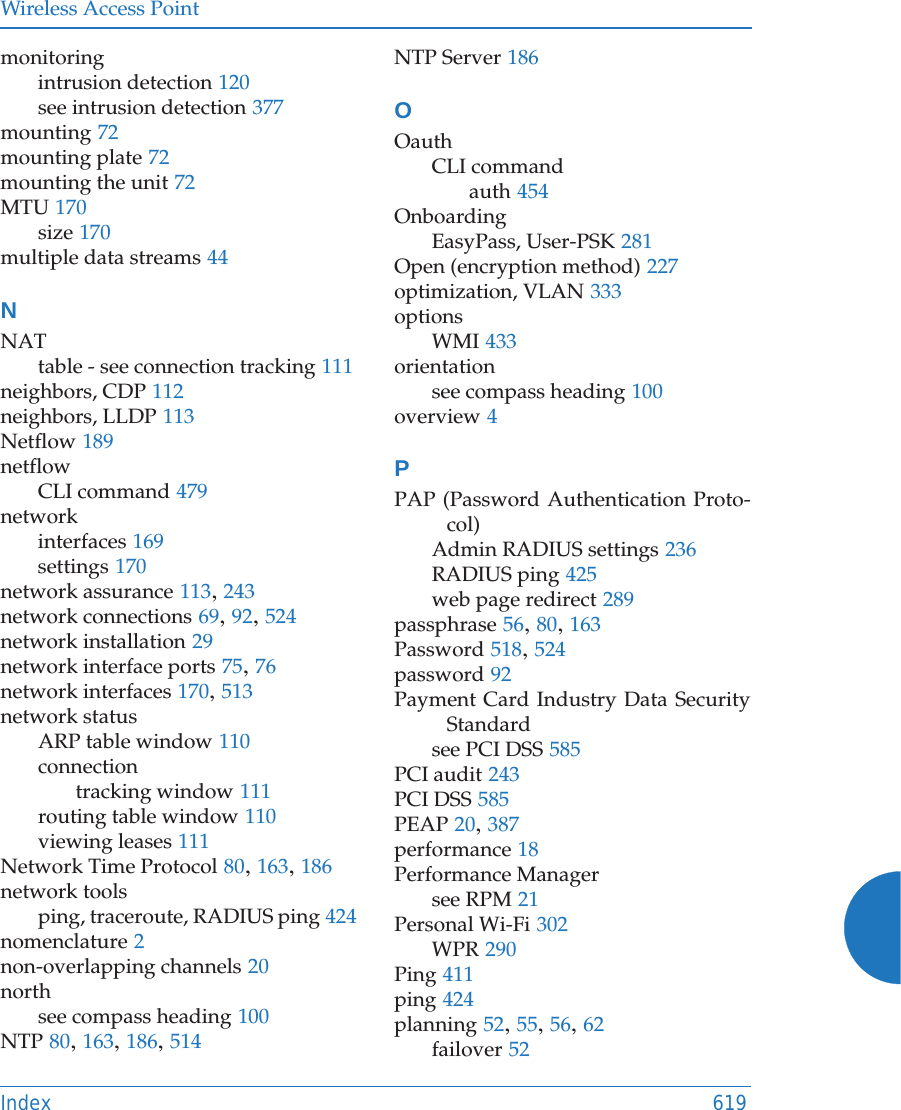
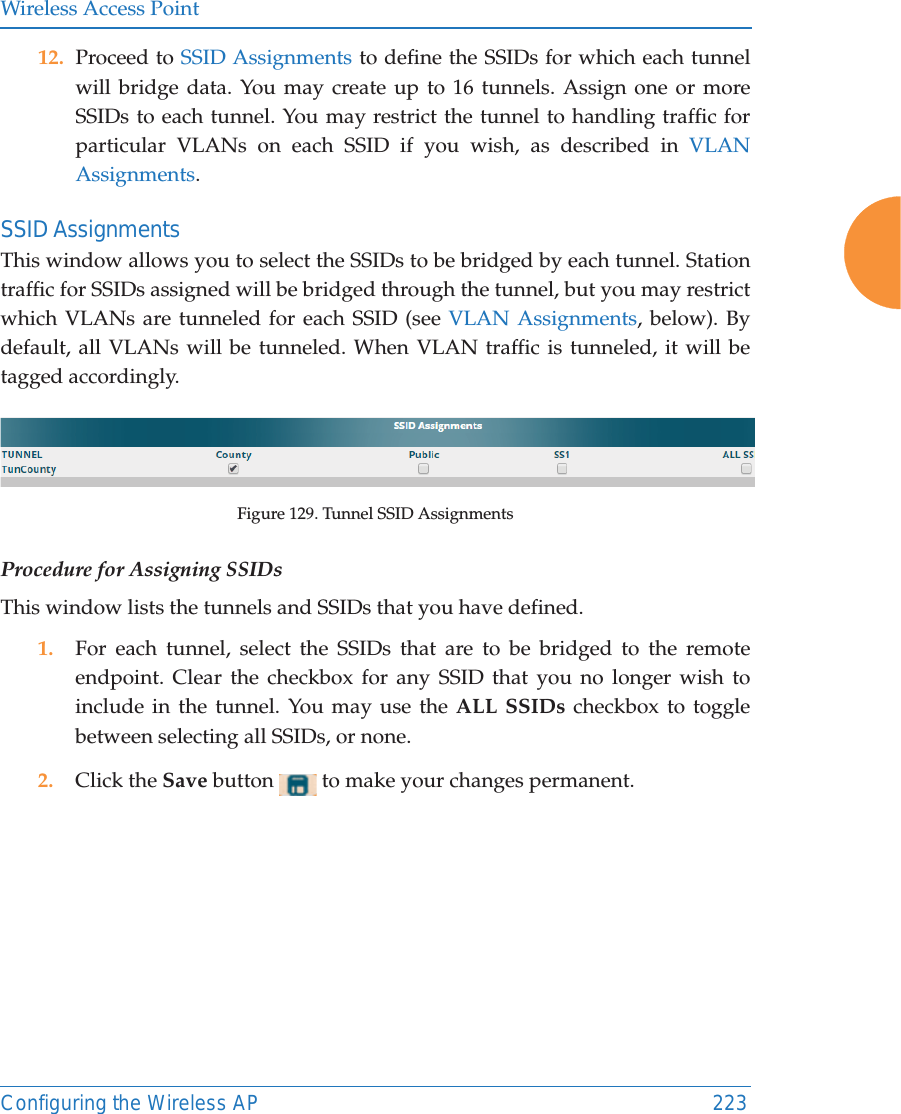
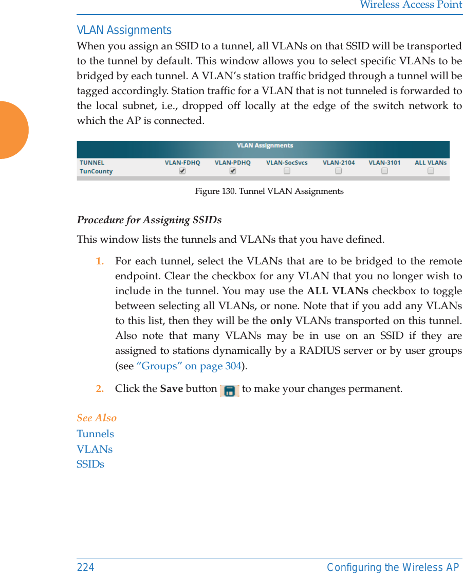
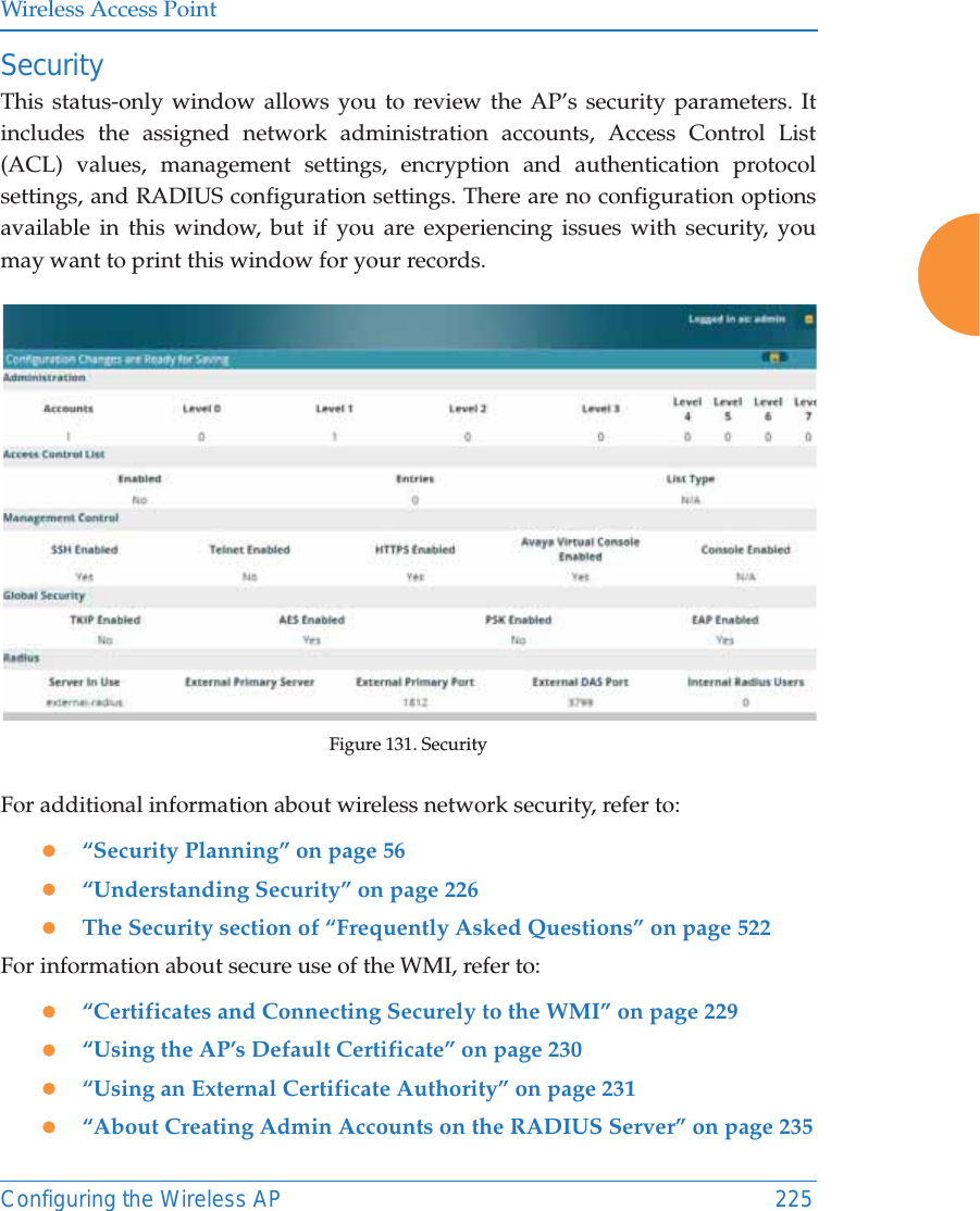
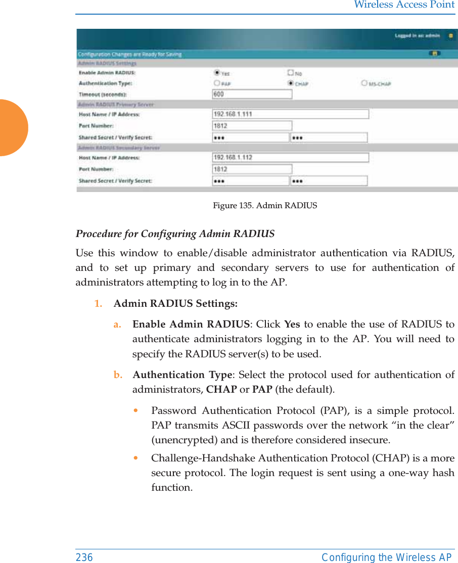
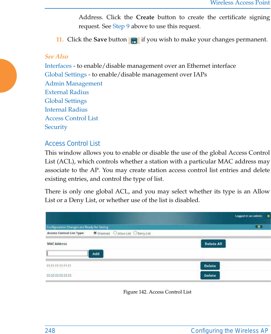
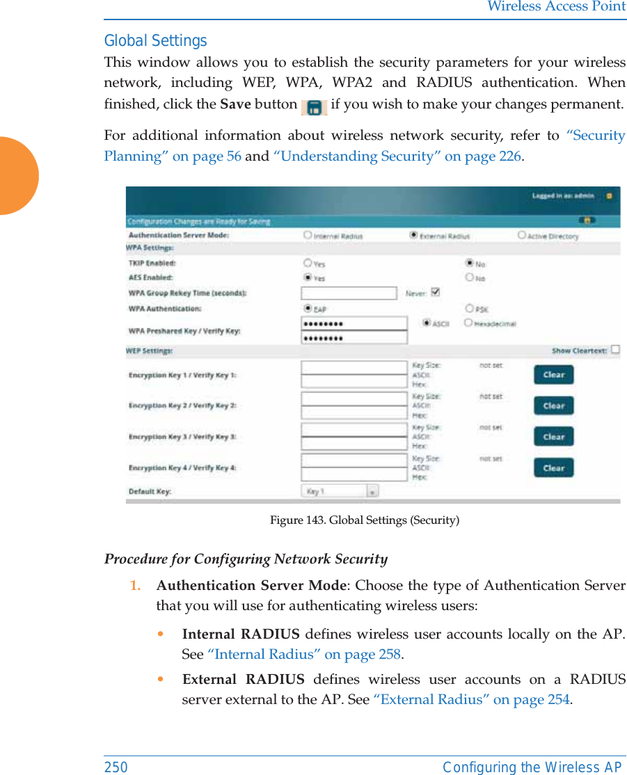
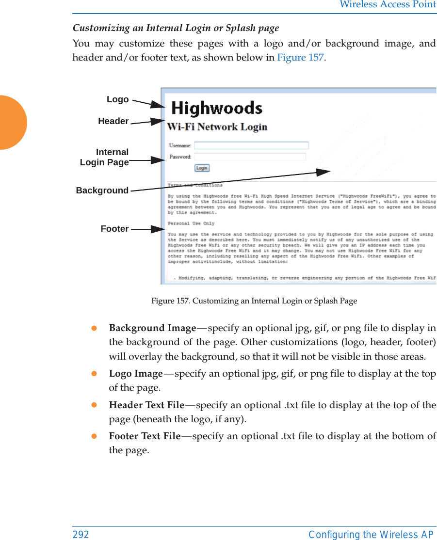
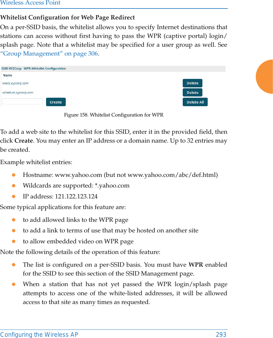
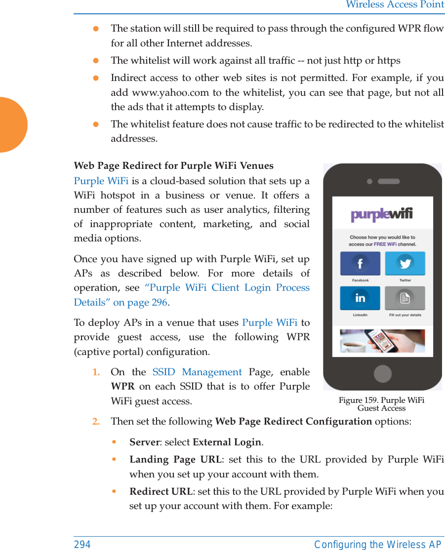
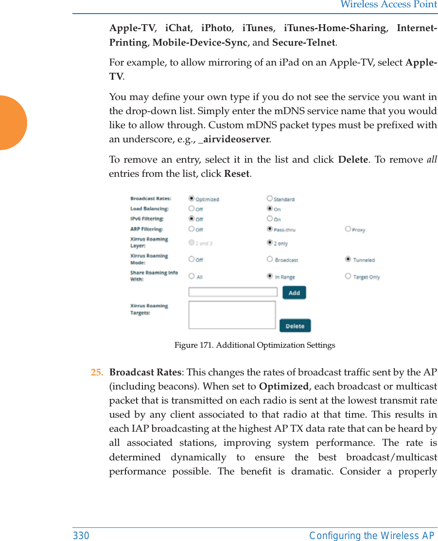
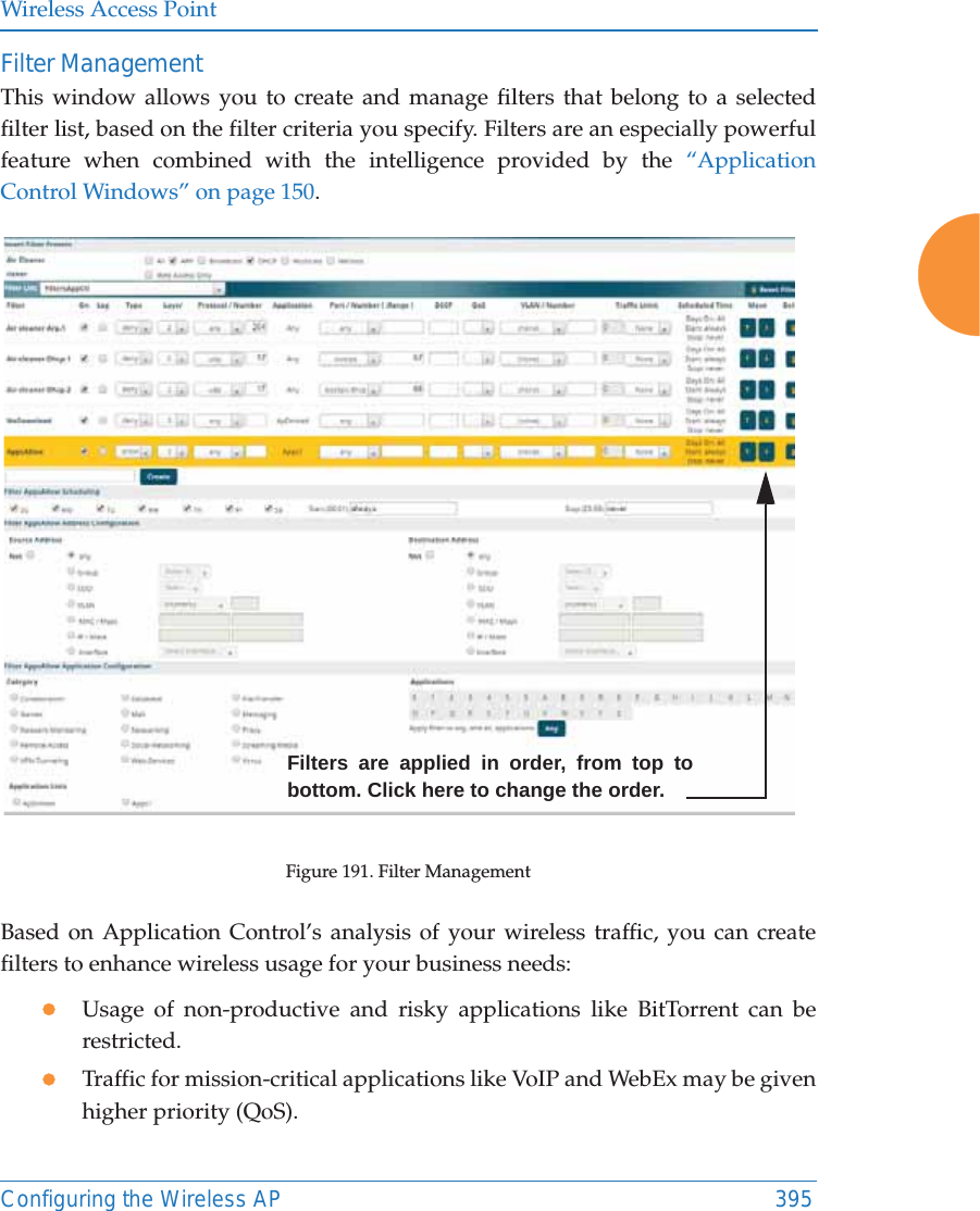
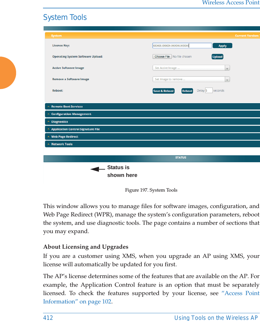
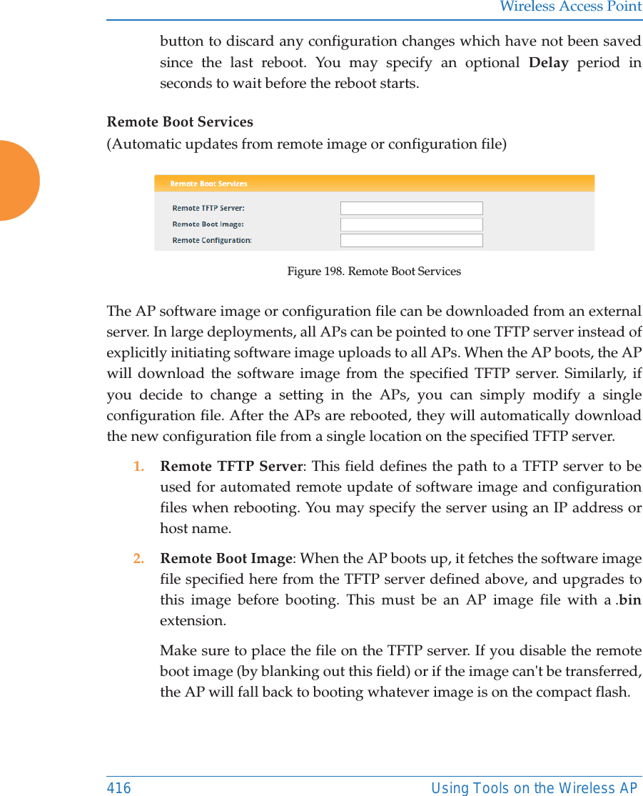
![Wireless Access Point222 Configuring the Wireless AP4. Local Endpoint: Enter the IP address of the AP Gigabit or 10 Gigabit port where the tunnel is to begin.5. Primary Remote Endpoint: Enter the IP address of the remote endpoint of the tunnel.6. Secondary Remote Endpoint: This provides a failover capability. If the primary tunnel fails, traffic is switched over to the secondary tunnel. Enter the IP address of the remote endpoint of the secondary tunnel.7. DHCP Option: When this option is enabled, the AP snoops station DHCP requests and inserts relay agent information (Option 82, in the CIRCUIT-ID sub-option) into these DHCP packets. Information inserted includes AP BSSID, SSID name, and SSID encryption type. You may use this option here or on the SSID Management page, but not in both places.Information is inserted as a colon-separated text string in the CIRCUIT ID value field in this format: [AP_MAC];[SSID];[ENC][AP_MAC] length = 17 (aa:bb:cc:dd:ee:ff)[SSID] length = length of SSID name[ENC] length = 1 (encryption type: 'o' = open, 's' = non-open)Note that this is a different format than is used for Option 82 with SSIDs.8. MTU: Set maximum transmission unit (MTU) size. 9. Interval: The tunnel mechanism will ping the current remote endpoint periodically to ensure that it is still reachable. Enter the ping interval (in seconds).10. Failures: Enter the number of consecutive ping failures that will cause the AP to consider the tunnel to be down. tunnel to failover to the other remote endpoint.11. Click the Save button if you wish to make your changes permanent.](https://usermanual.wiki/Cambium-Networks/XR620.User-Manual/User-Guide-3002682-Page-248.png)
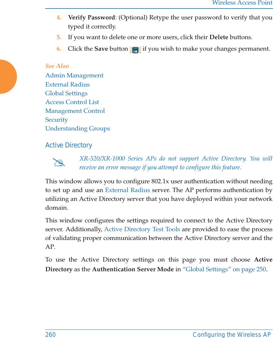
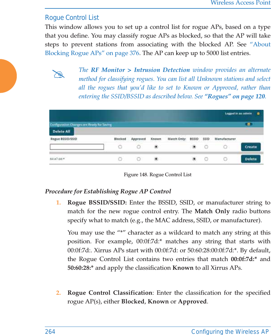
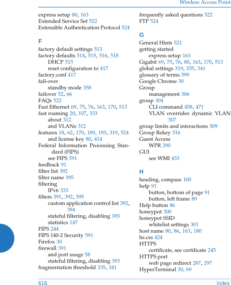
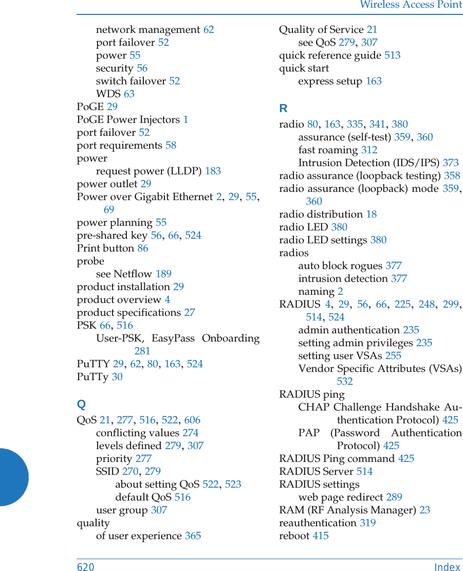
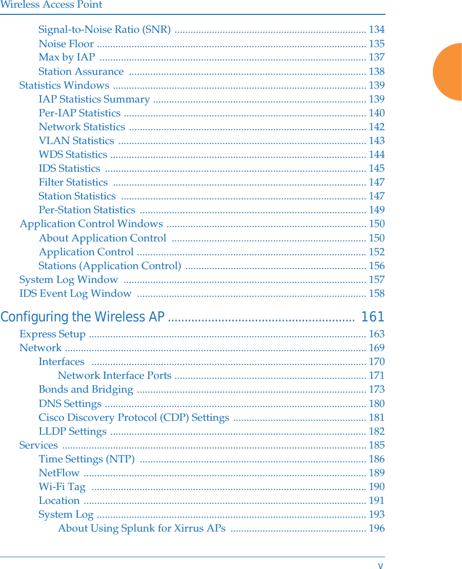
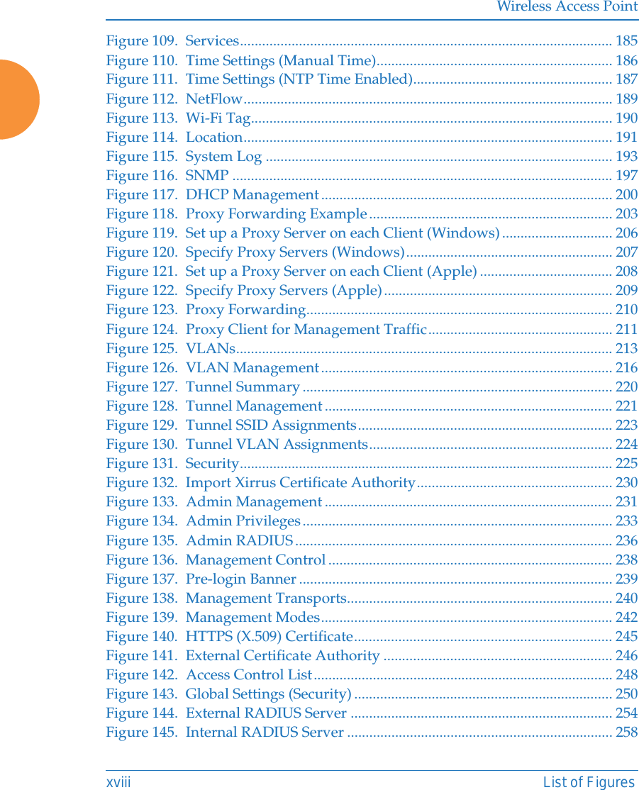
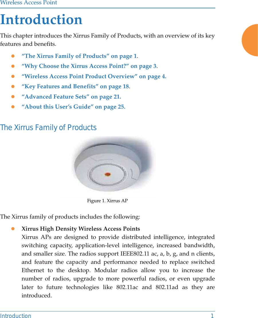
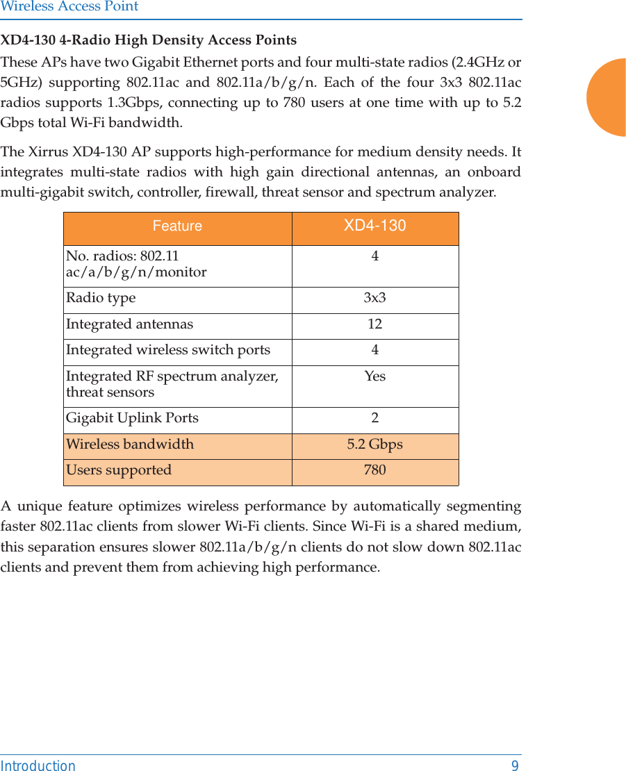
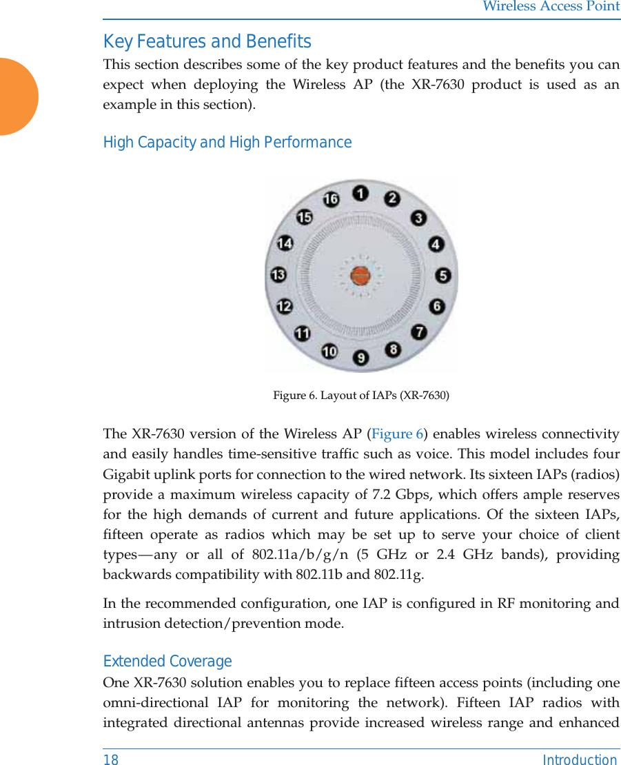
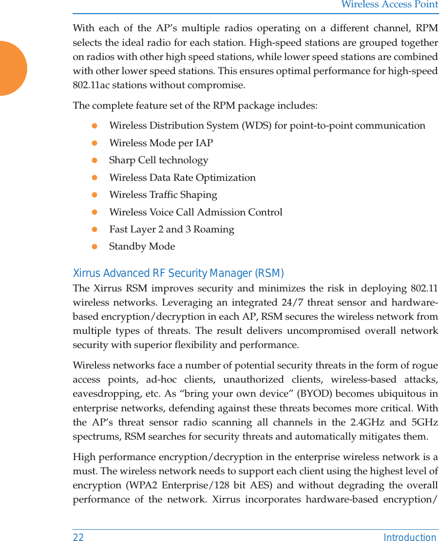
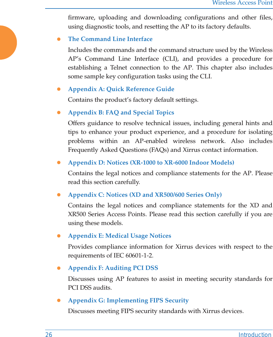
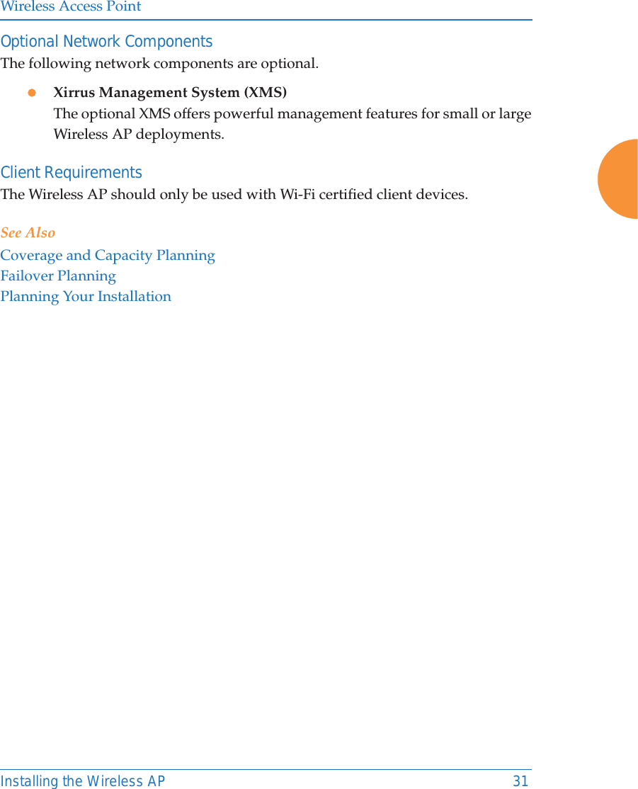
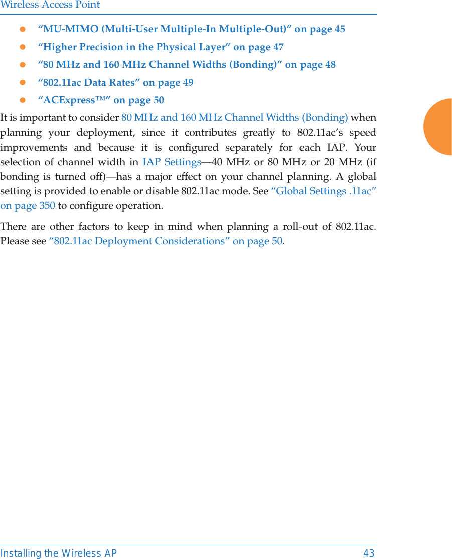
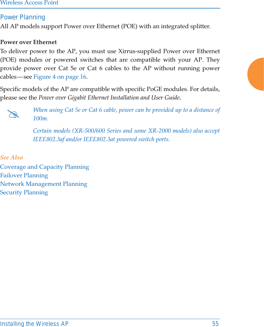
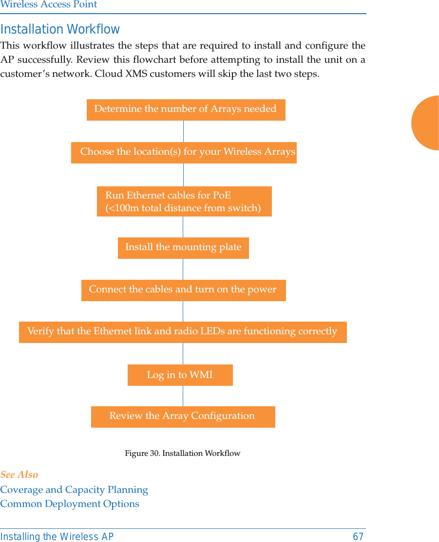
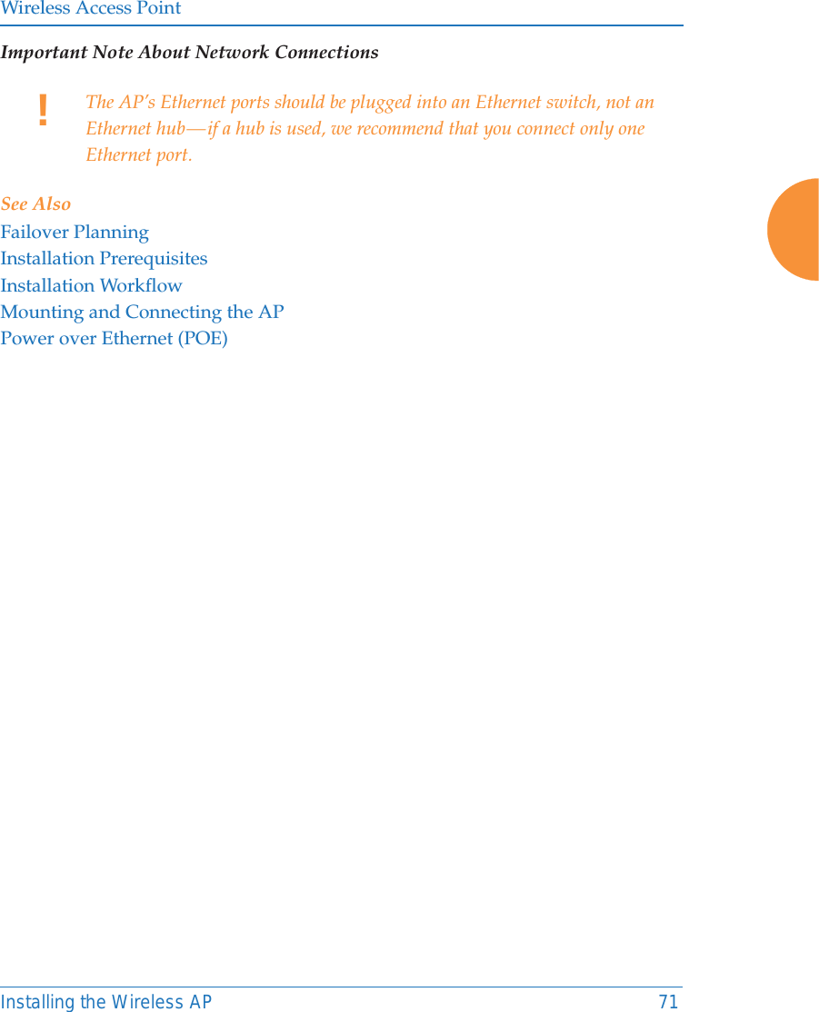
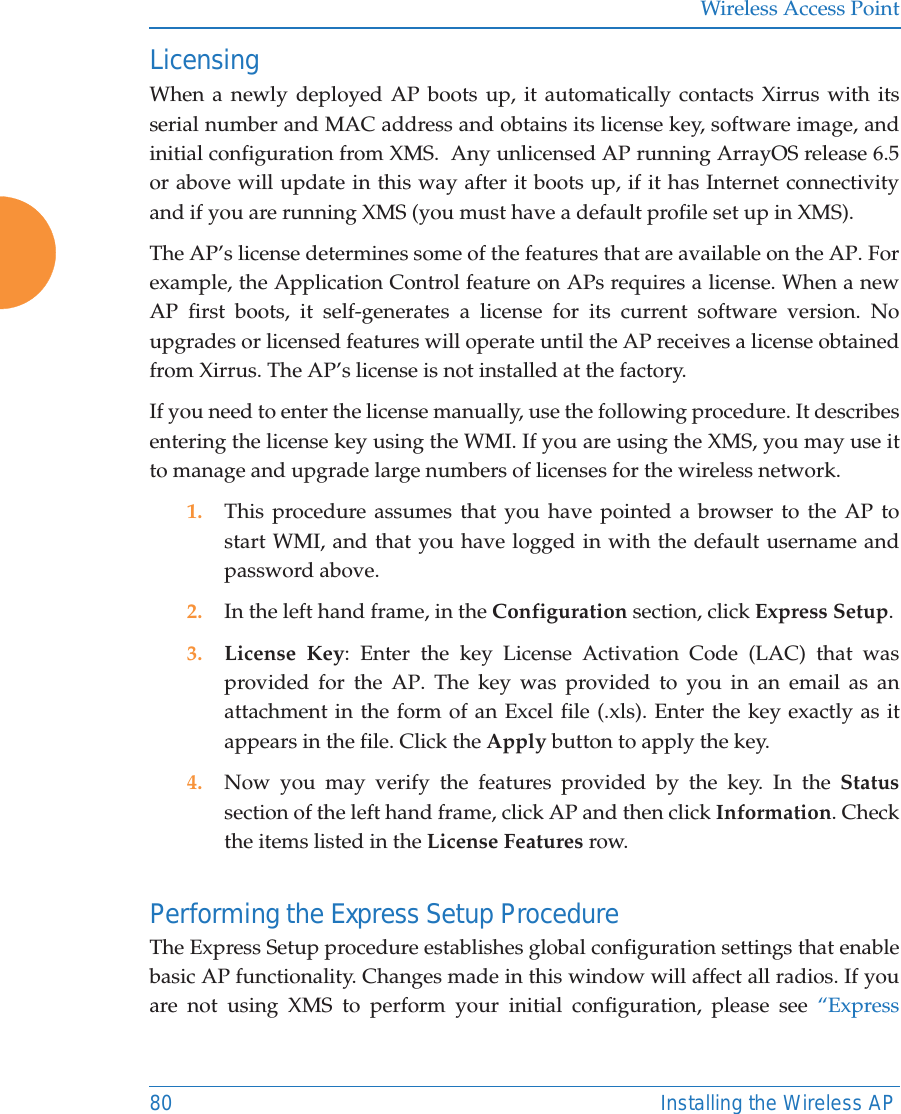
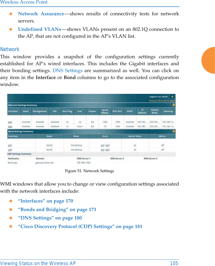
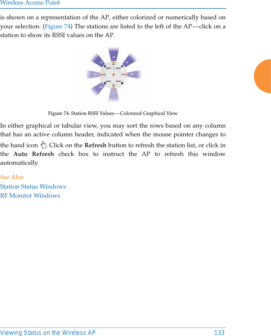
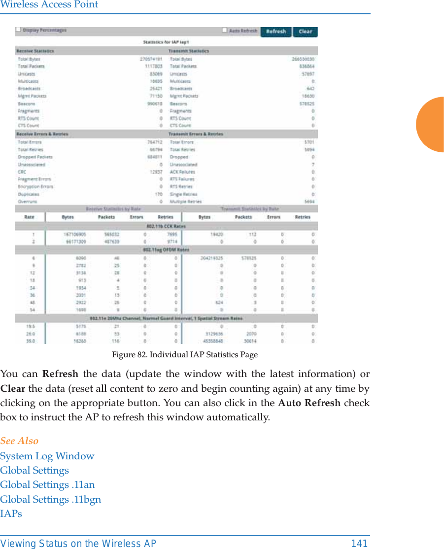
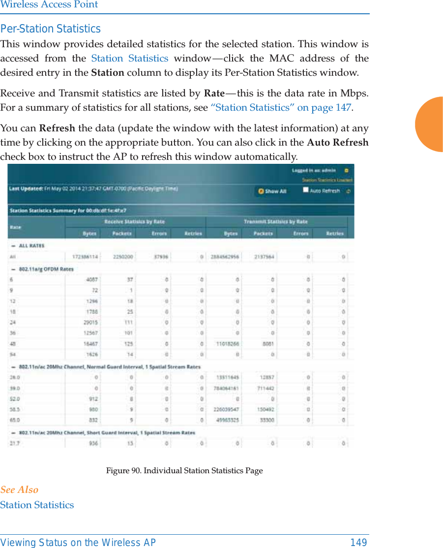
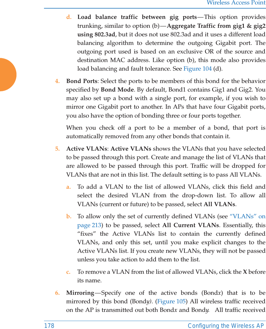
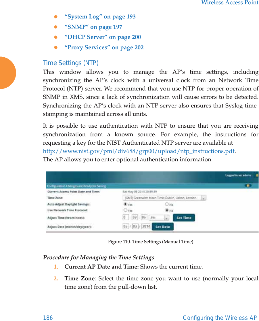
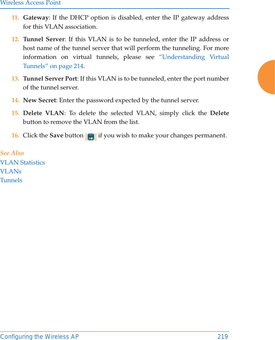
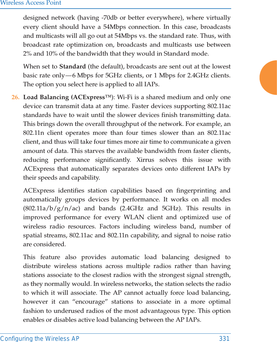
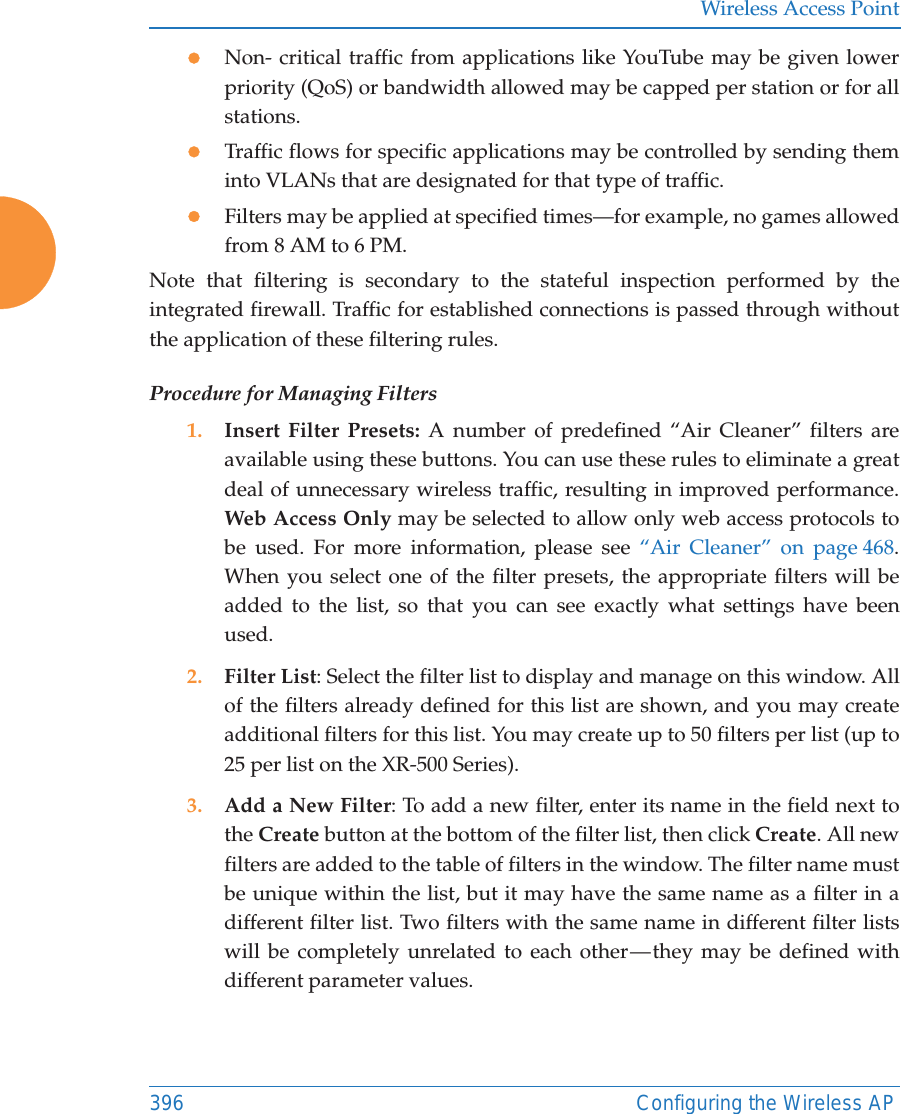
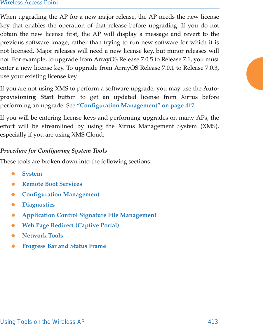
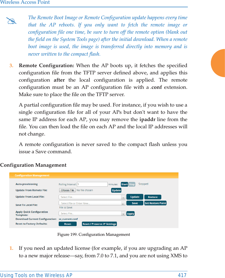
![Wireless Access Point266 Configuring the Wireless APFigure 149. OAuth 2.0 Management - Token ListProcedure for Obtaining a Token and Accessing RESTful API on the AP1. Present User Credentials for a Permanent TokenA user-developed application must register by presenting the following information to the URL below:https://[AP hostname or IP address]/oauth/authorize •grant_type: password•username: username of an administrator account on the AP.•client_id: username of an administrator account on the AP(username and client_id must match).•password: password for the same administrator account on the APThe OAuth Authorization API provides a permanent token that the application may use to access the RESTful API. This token remains valid until the administrator revokes the token on the OAuth 2.0 Managementpage, unless the token file somehow becomes corrupted or is removed from the AP’s file system. The token will be removed if the original account associated with it is deleted. 2. Access the RESTful APIOnce registration is completed and a permanent token has been provided, your application may access the API using the client_id and the token at the following URL: https://[AP hostname or IP address]/api/v3/[api-name] ](https://usermanual.wiki/Cambium-Networks/XR620.User-Manual/User-Guide-3002682-Page-292.png)

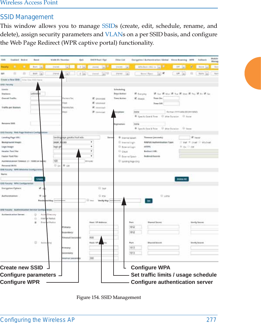
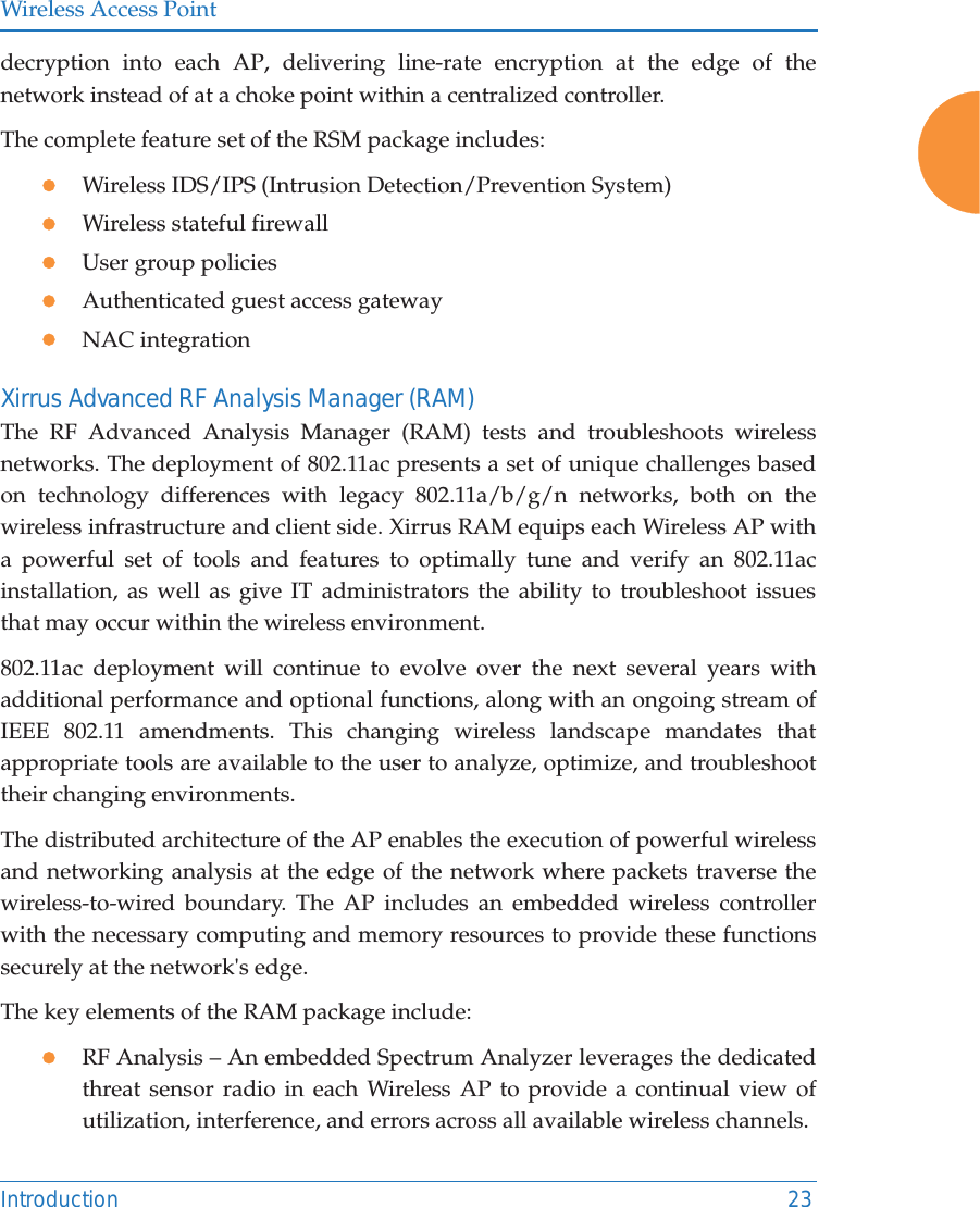
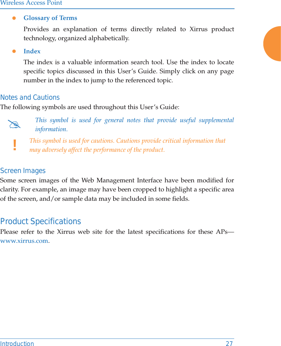
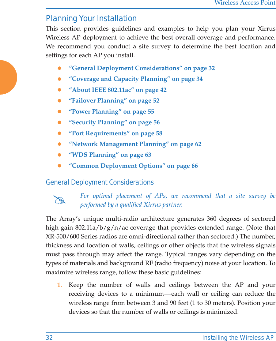
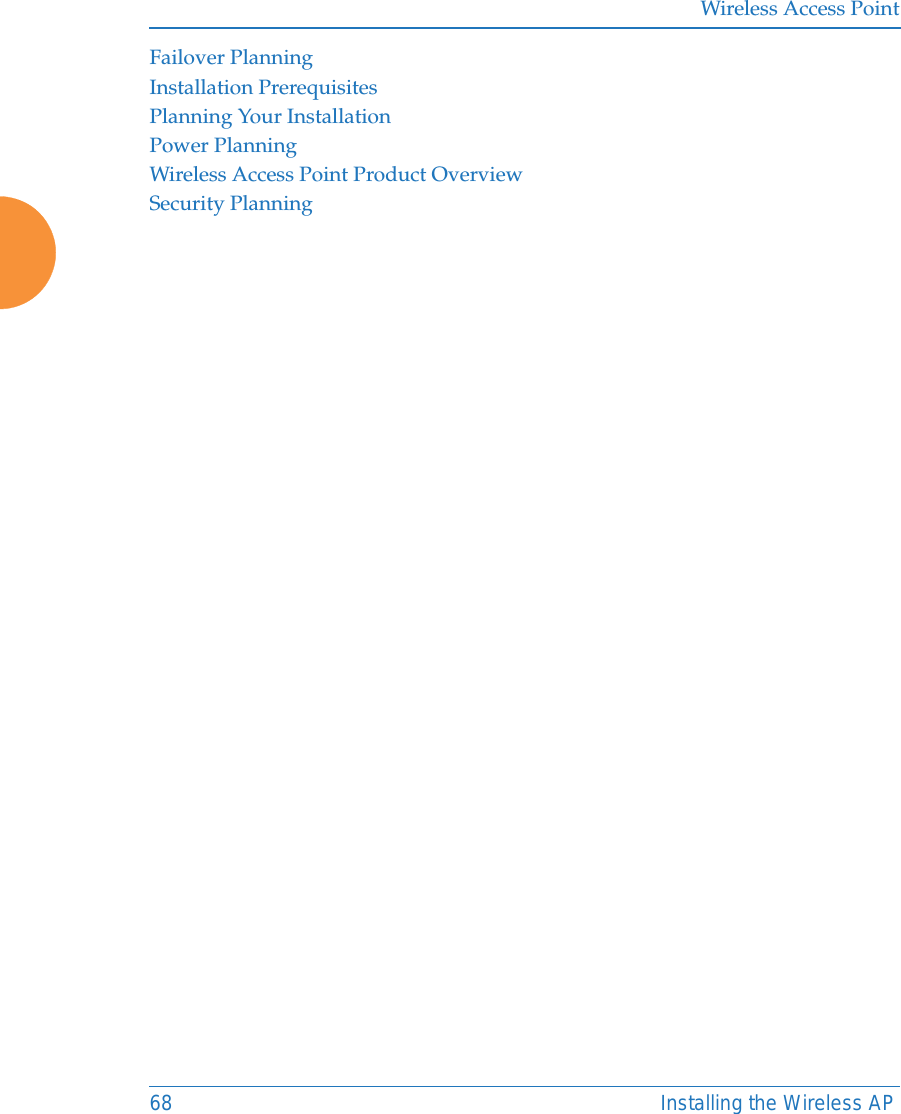
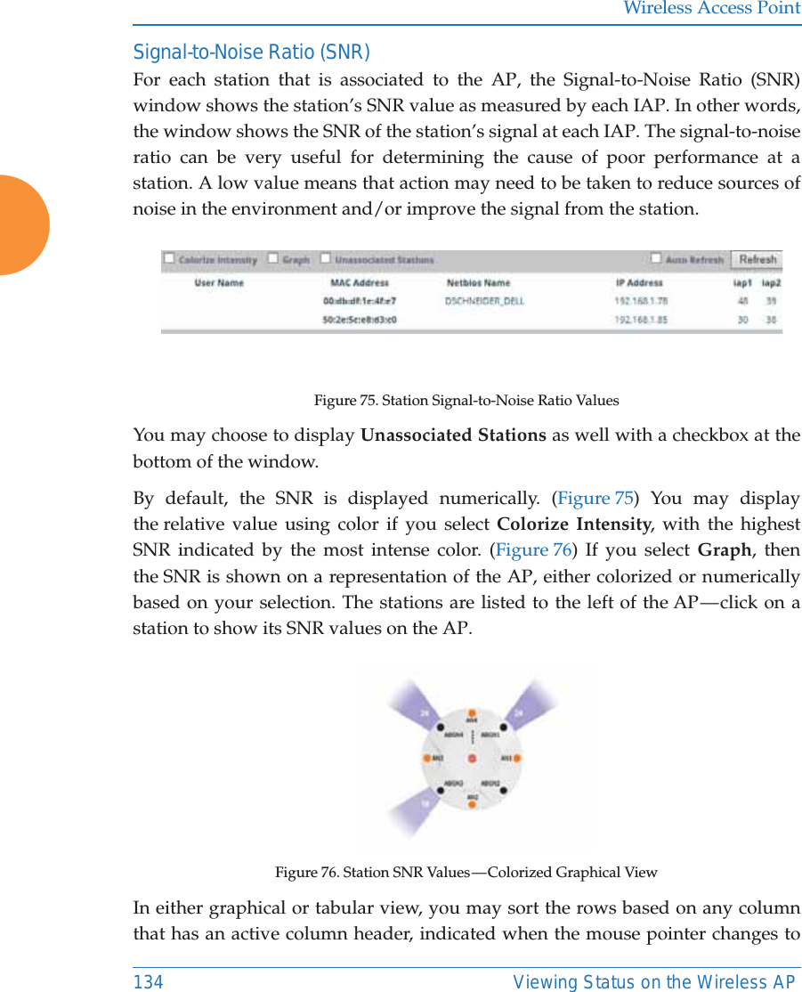
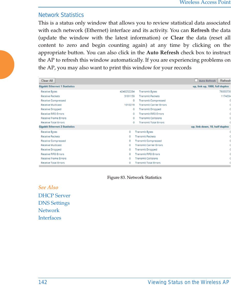
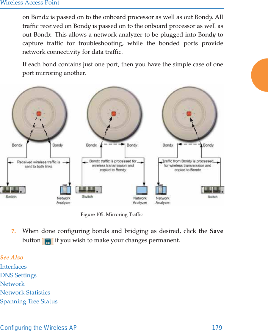
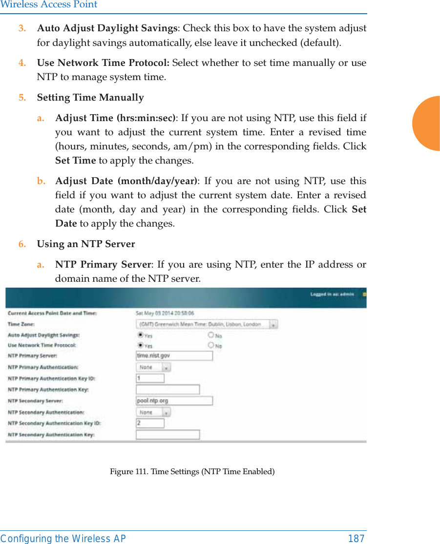
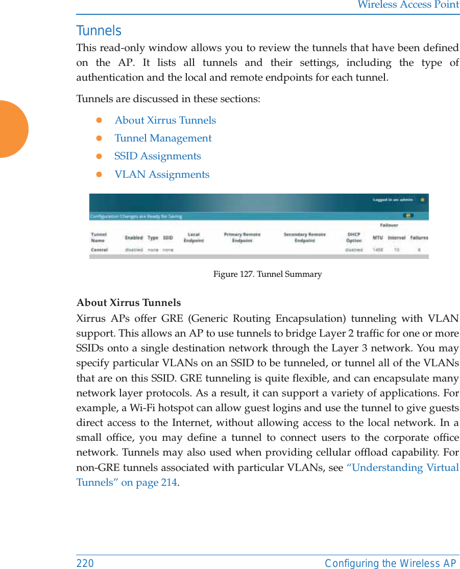
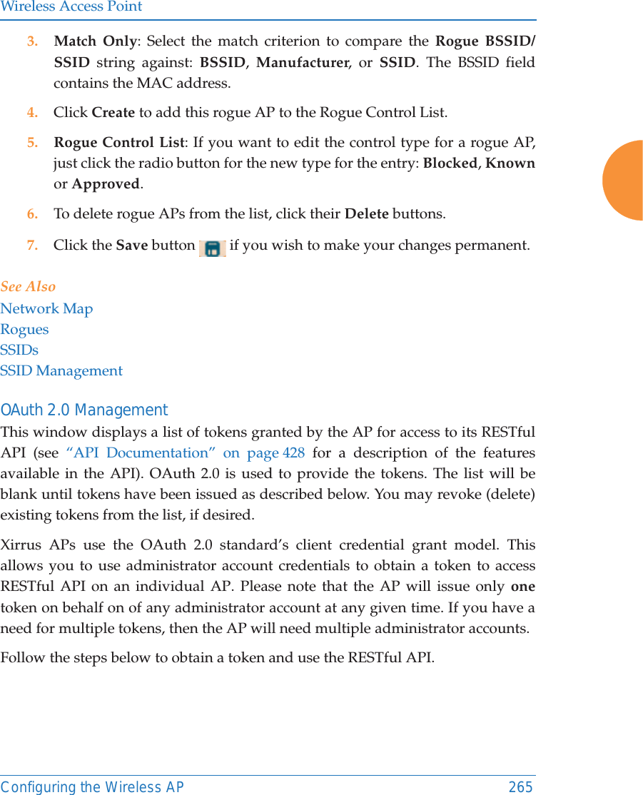
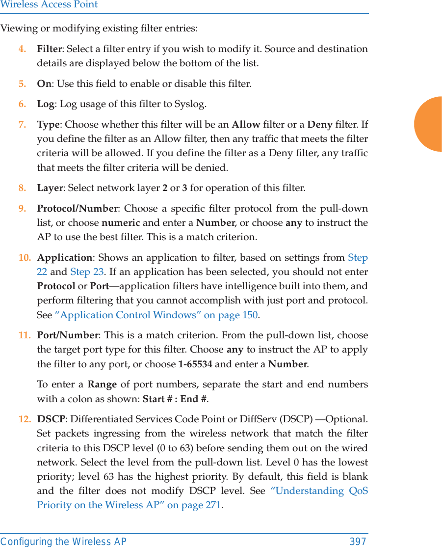
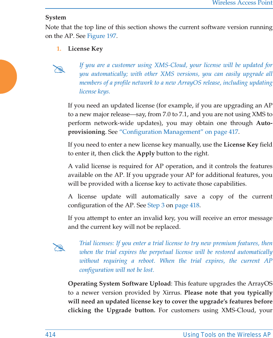
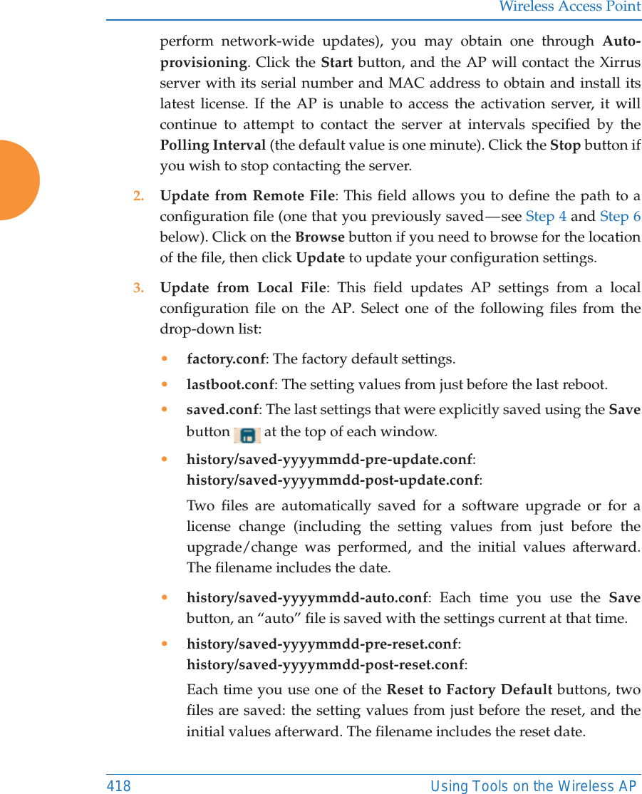
![Wireless Access PointConfiguring the Wireless AP 2797. QoS: (Optional) Select a value in this field for QoS (Quality of Service) priority filtering. The QoS value must be one of the following: •0 — The lowest QoS priority setting, where QoS makes its best effort at filtering and prioritizing data, video and voice traffic without compromising the performance of the network. Use this setting in environments where traffic prioritization is not a concern.•1 — Medium, with QoS prioritization aggregated across all traffic types.•2 — High, normally used to give priority to video traffic.•3 — The highest QoS priority setting, normally used to give priority to voice traffic.The QoS setting you define here will prioritize wireless traffic for this SSID over other SSID traffic, as described in “Understanding QoS Priority on the Wireless AP” on page 271. The default value for this field is 2. 8. DHCP Pool: If you want to associate an internal DHCP pool to this SSID, choose the pool from the pull--down list. An internal DHCP pool must be created before it can be assigned. To create an internal DHCP pool, go to “DHCP Server” on page 200.9. DHCP Option: When this option is enabled, the AP snoops station DHCP requests and inserts relay agent information into these DHCP packets (option 82, in the CIRCUIT-ID sub-option). Information inserted includes AP MAC address and SSID name. You may use this option here or on the Tunnel Management page, but not in both places. Information is inserted as a colon-separated text string in the CIRCUIT ID value field, in this format: [AP_MAC]:[SSID][AP_MAC] length = 17 (aa-bb-cc-dd-ee-ff)[SSID] length = length of SSID nameExample: aa-bb-cc-dd-ee-ff:mySSIDNote that the MAC address uses dashes as separators, and that format isdifferent than that used for Option 82 with Tunnels.](https://usermanual.wiki/Cambium-Networks/XR620.User-Manual/User-Guide-3002682-Page-305.png)
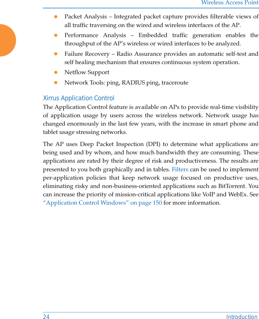
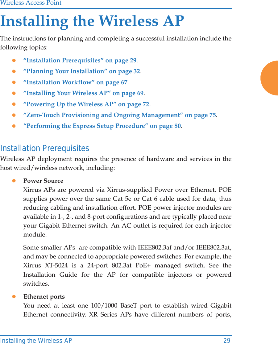
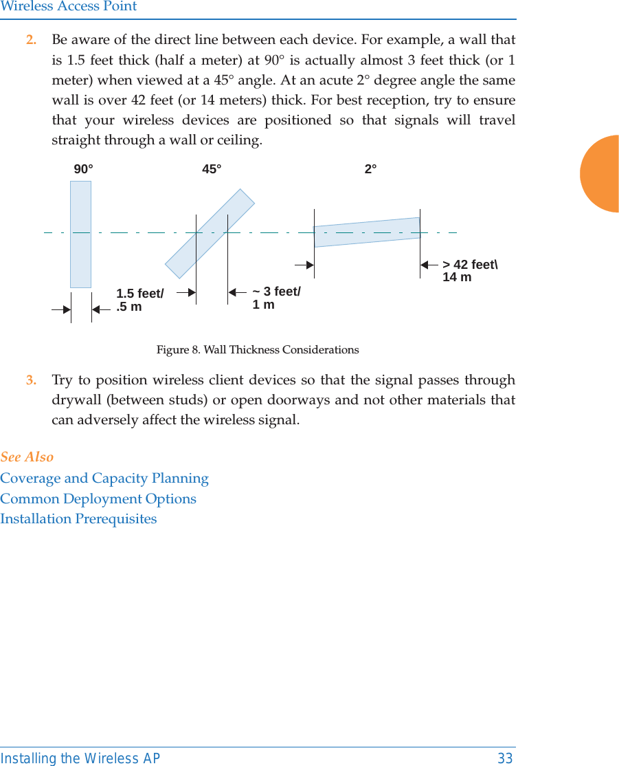
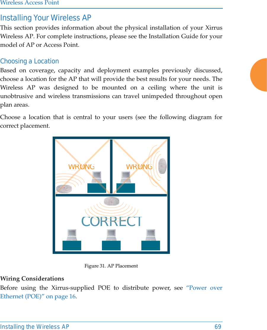
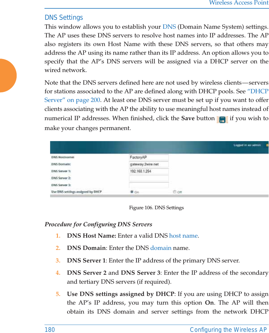
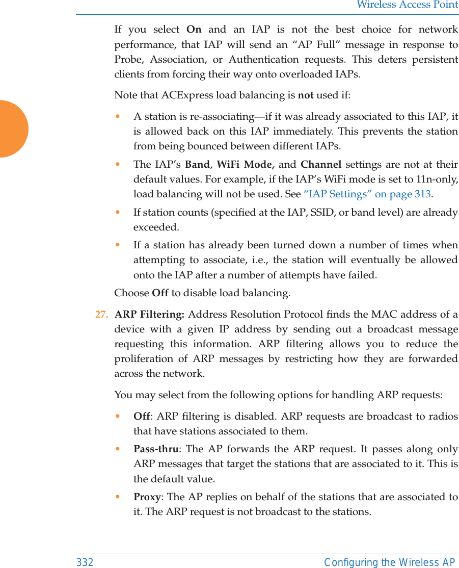
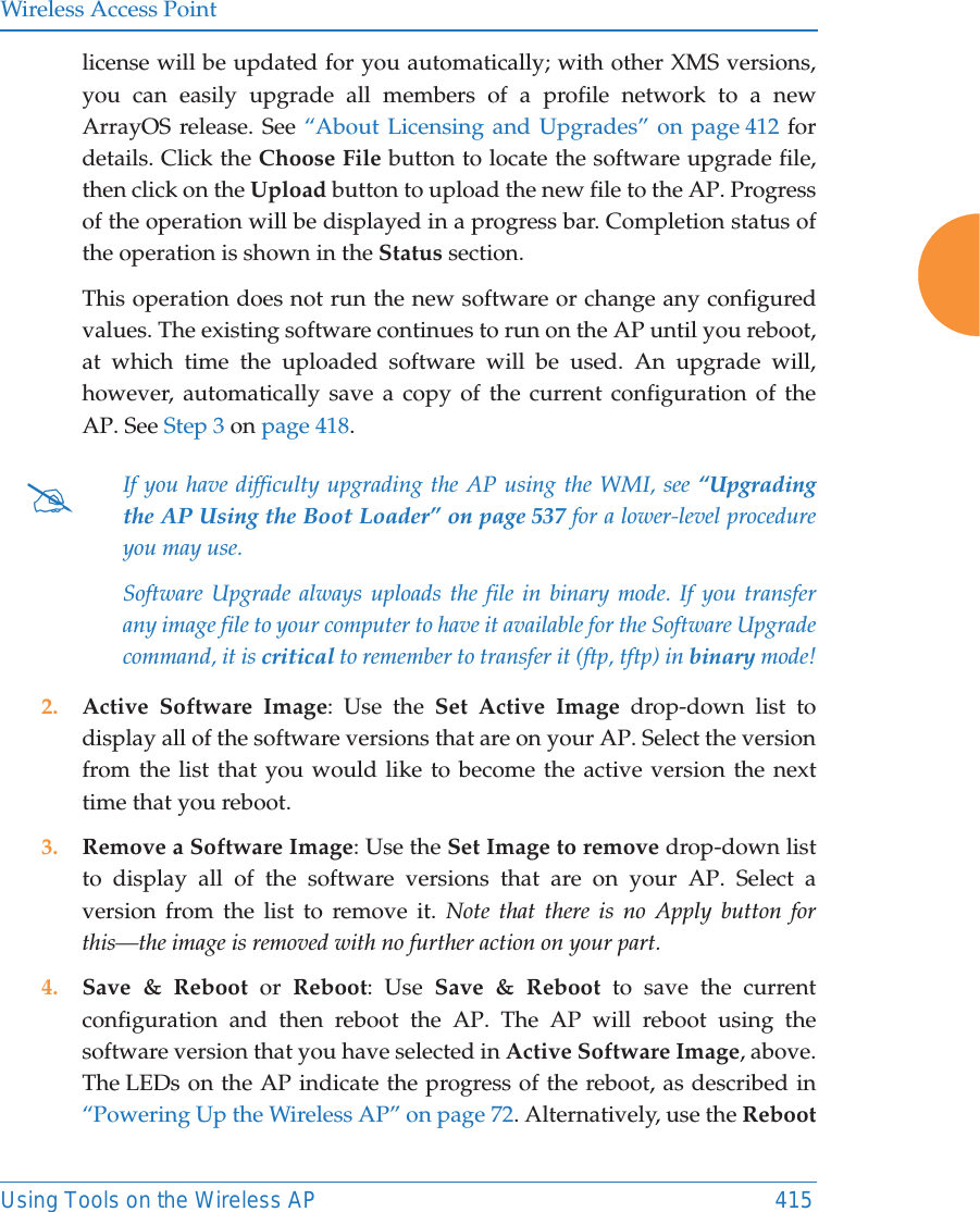
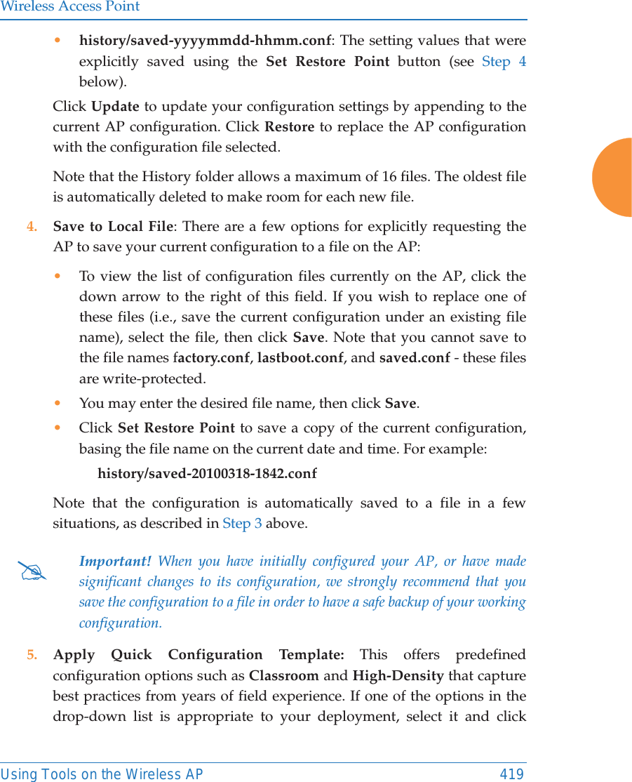
![Wireless Access PointConfiguring the Wireless AP 28521. Rename SSID: Use this field if you wish to change the name of an SSID without changing any of its other settings. For example, a convention center might wish to change the SSID name based on the name of the current exhibition. Scheduling 22. Days Active: Choose Everyday if you want this SSID to be active every day of the week, or select only the specific days that you want this SSID to be active. Days that are not checked are considered to be the inactive days.23. Time Active: Choose Always if you want this SSID active without interruption, or enter values in the Time On and Time Off fields to limit the time that this SSID is active. 24. Date on: Use this and the following two fields for SSID Scheduling—this lets you set up an SSID in advance and specify a period of time for the SSID to be in service. For example, a convention center might wish to set up SSIDs ahead of time for exhibitions that are scheduled for the next six months, and have each SSID be used only for the specified period. The SSID must be Enabled (see Step 1 on page 278), or the scheduling settings will be ignored. Note that once the SSID has reached its scheduled time and is in service, it will then obey the settings for Days Active and Time Active above. Set Date on to none (the default) if you don’t want this SSID to be delayed until later—that is, it will be put in service starting immediately. Select Specific Date & Time to have the SSID start become active at the specified date and time. Use the format YYYY-MM-DD [HH:MM], where time (hour and minute) is optional. For example, enter 2016:09:29 08:00. Use After Duration to delay for the specified amount of time in days, hours, and minutes, before the SSID is in service (use the format DD HH:MM, including the hours and minutes). For example, to have the SSID become valid after one day, one hour and 30 minutes have passed, enter 1 01:30.](https://usermanual.wiki/Cambium-Networks/XR620.User-Manual/User-Guide-3002682-Page-311.png)
![Wireless Access Point286 Configuring the Wireless AP25. Use Date off to specify a date to take the SSID out of service without deleting it. At the specified date, the AP will turn the Enabled flag off. Leave Expiration and Date off set to none (the default) if you want this SSID to remain in service indefinitely after its scheduled start. Use Specific Date & Time to take the SSID out of service at the specified date and time. Use the format YYYY-MM-DD [HH:MM], where time (hour and minute) is optional. For example, enter 2016:09:29 18:00. Use After Duration to keep the SSID in service for the specified amount of time in days, hours, and minutes (use the format DD [HH:MM], where hours and minutes are optional). 26. Use Expiration to specify a date to delete this SSID when it is taken out of service at the specified date (i.e., this option cleans up after itself when it reaches the expiration time). Leave Expiration and Date off set to none(the default) if you want this SSID to remain in service indefinitely after its scheduled start. Use Specific Date & Time to delete the SSID at the specified date and time. Use the format YYYY-MM-DD [HH:MM], where time (hour and minute) is optional. For example, enter 2016:09:29 18:00. Use After Duration to keep the SSID in service for the specified amount of time in days, hours, and minutes (use the format DD [HH:MM], where hours and minutes are optional).27. Web Page Redirect Configuration: see “Web Page Redirect (Captive Portal) Configuration” on page 287.28. To delete an SSID, click its Delete button .29. Click the Save button if you wish to make your changes permanent.](https://usermanual.wiki/Cambium-Networks/XR620.User-Manual/User-Guide-3002682-Page-312.png)
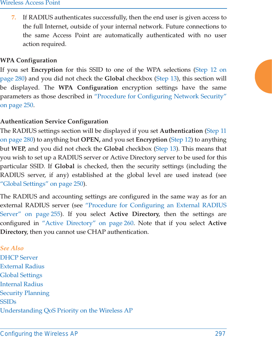
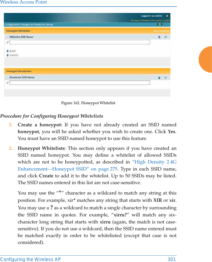
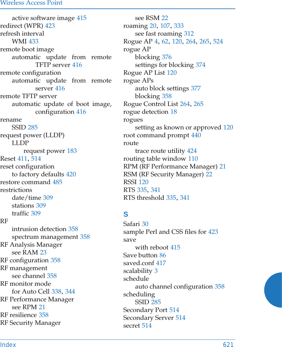
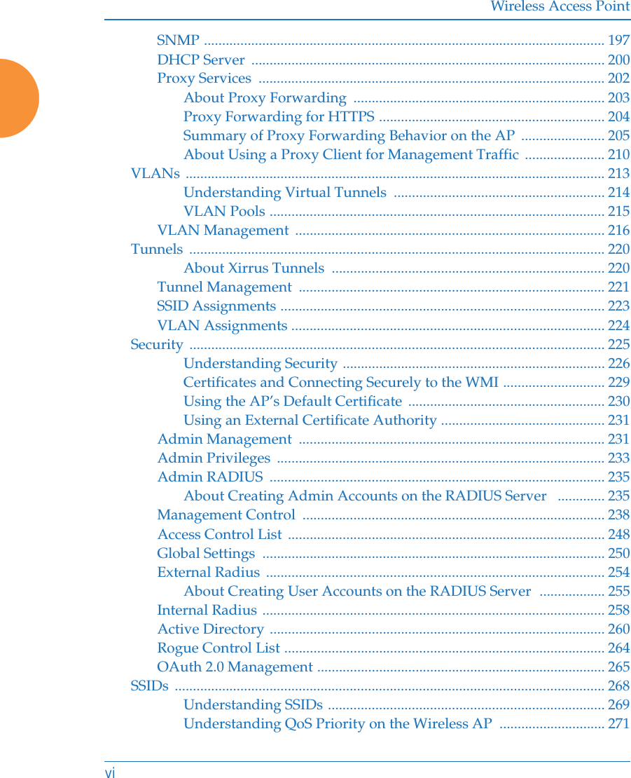
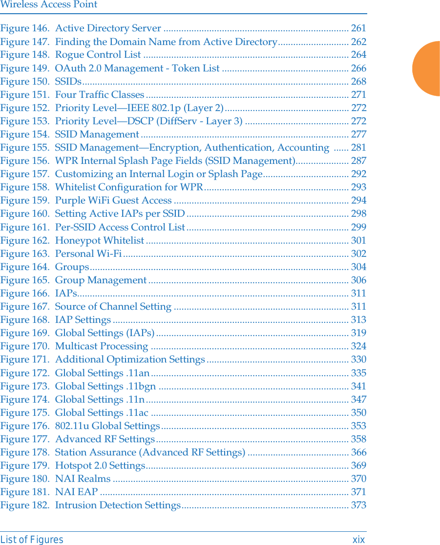
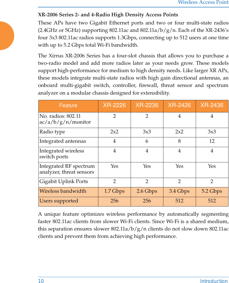
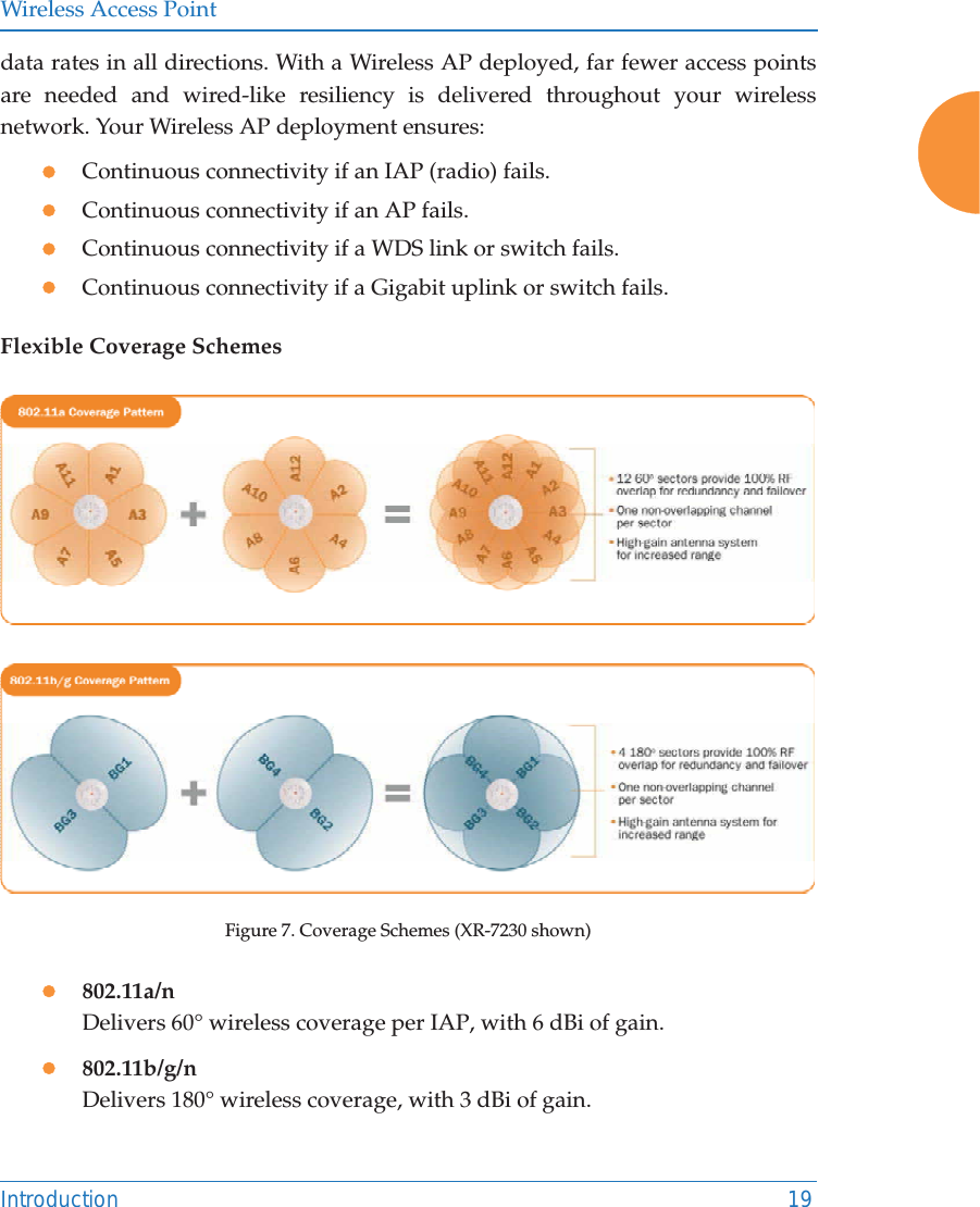
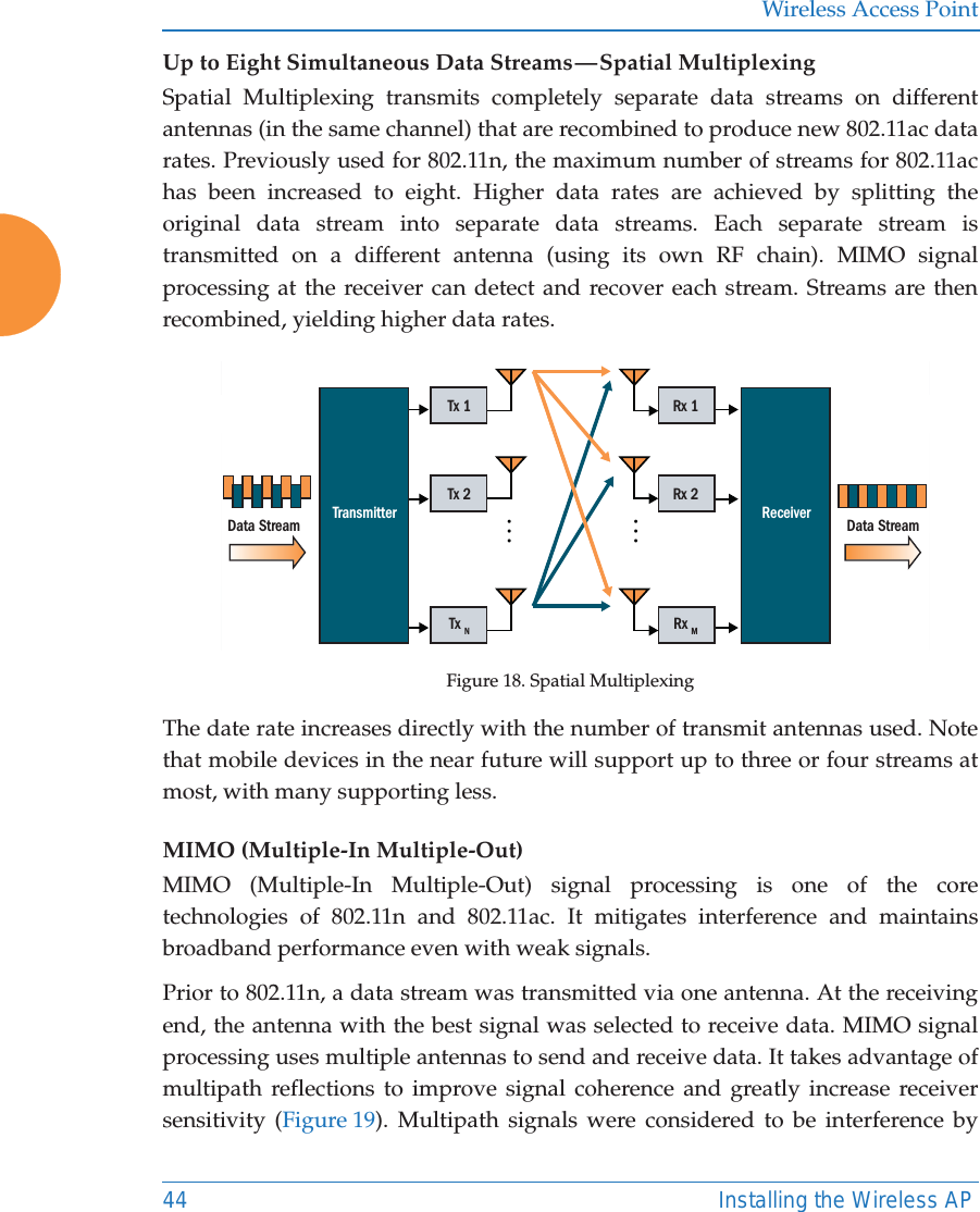
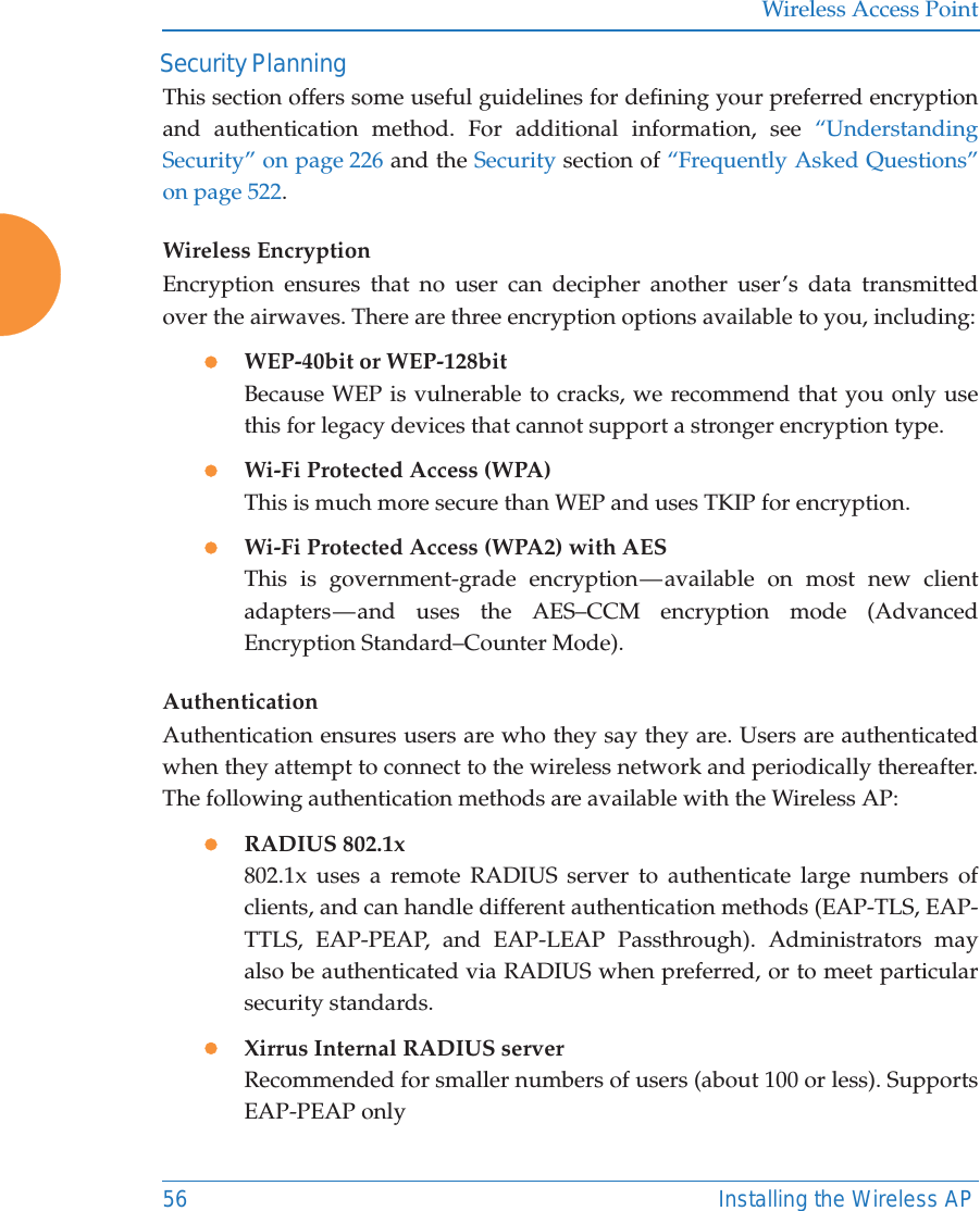
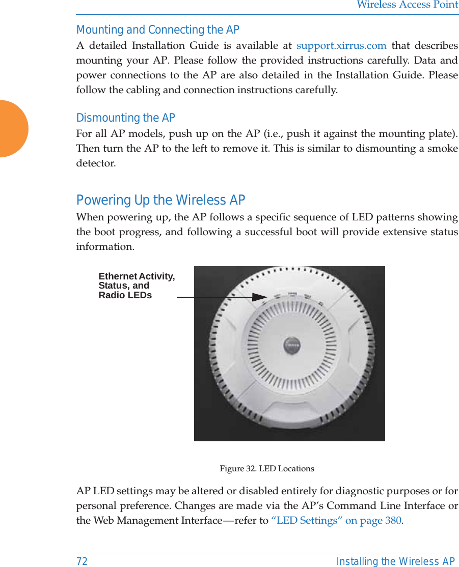
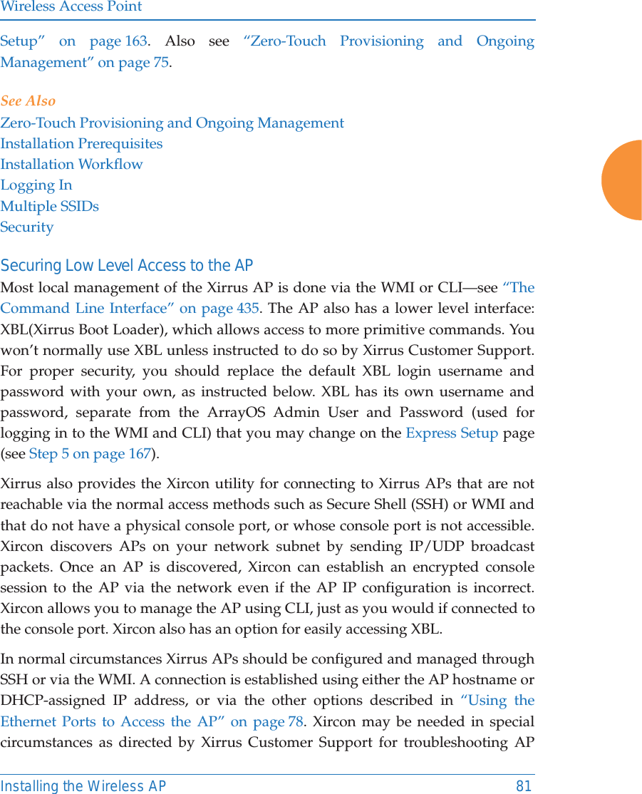
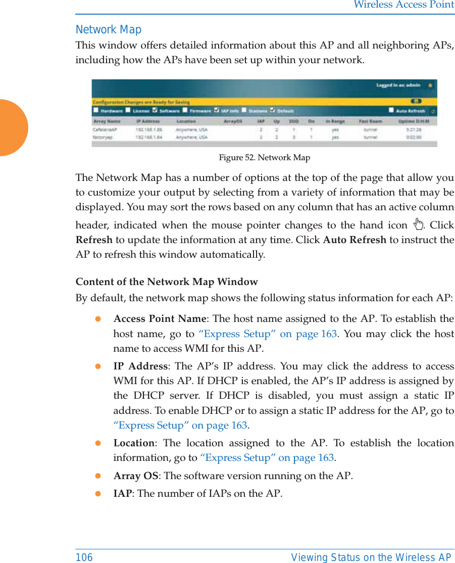
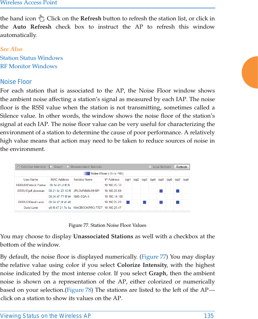
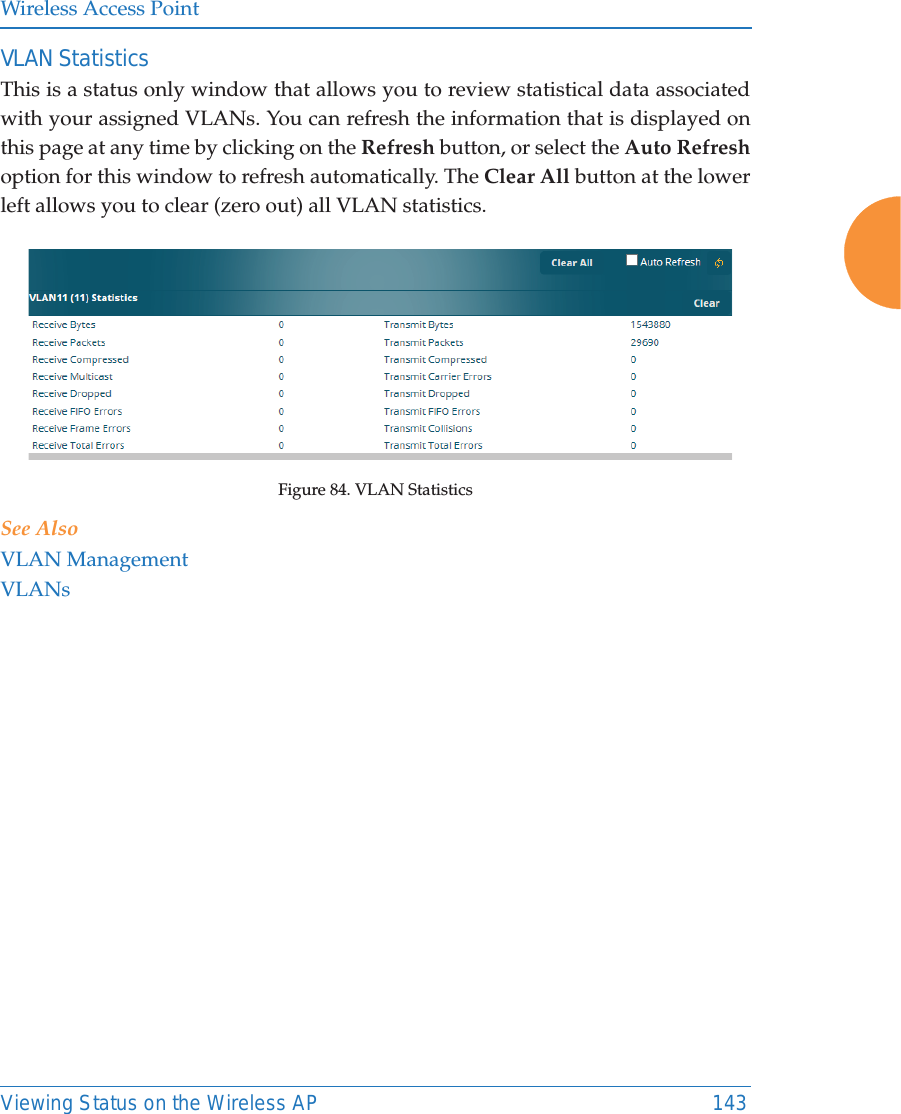
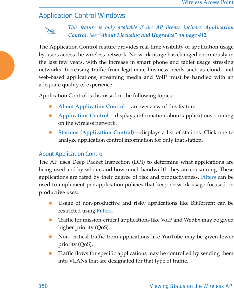
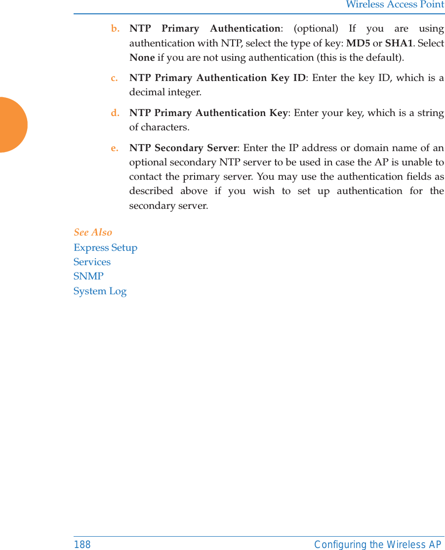
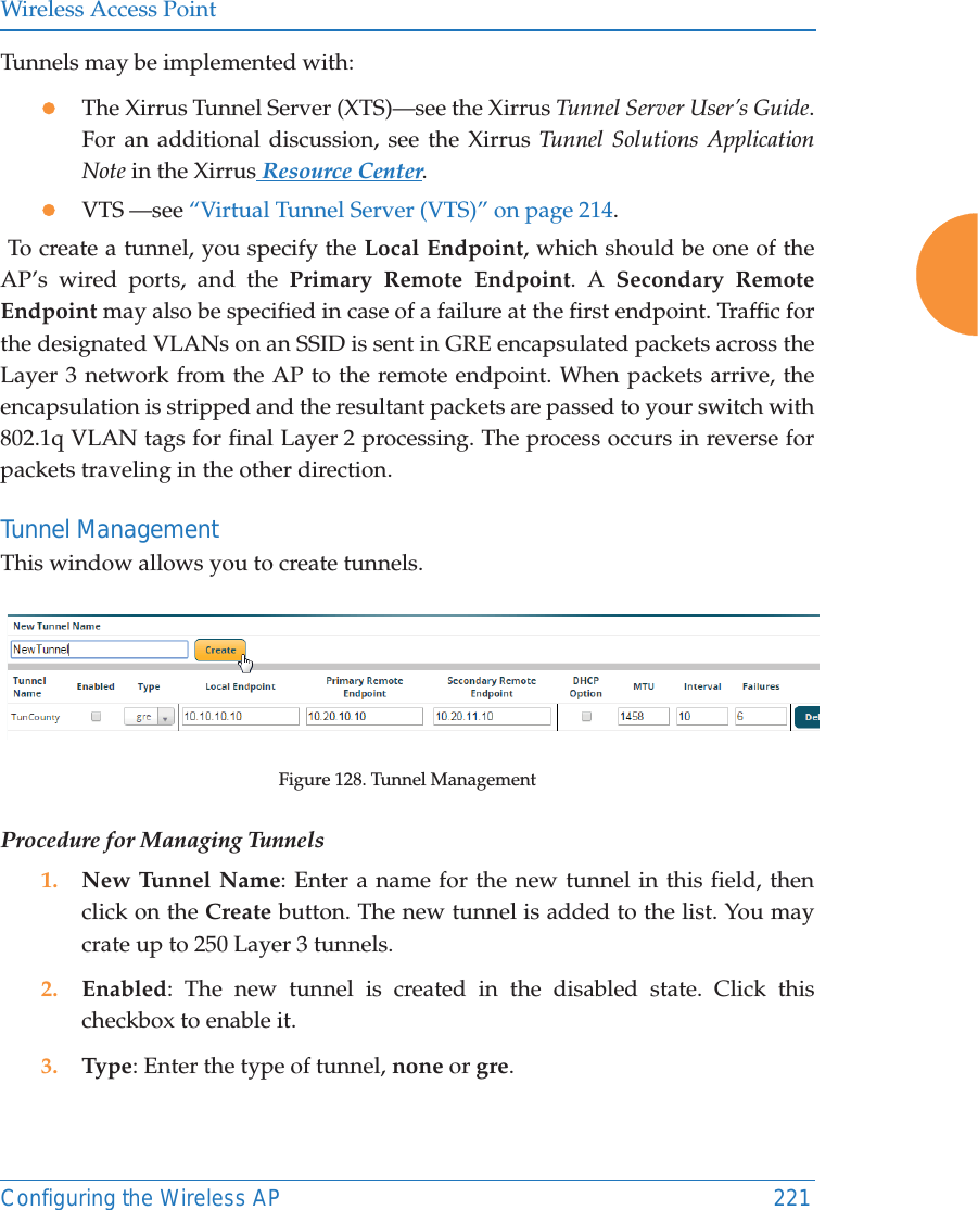
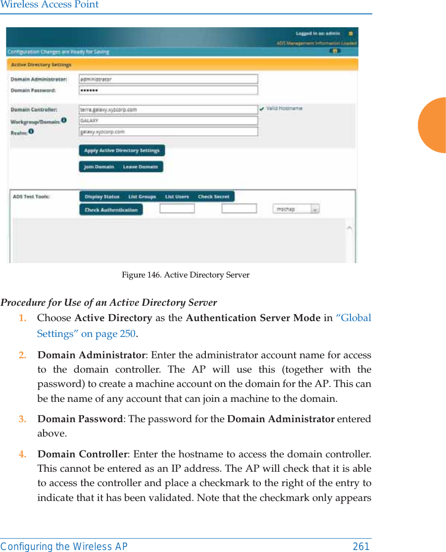
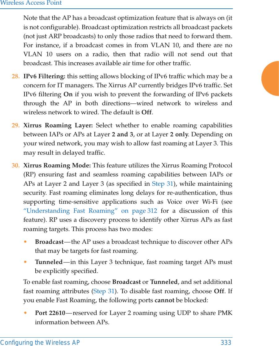
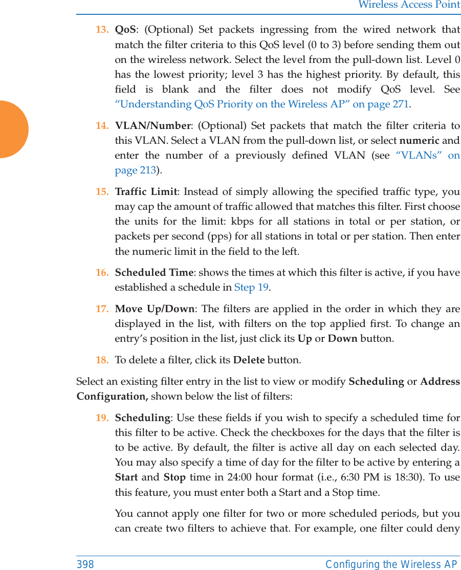
![Wireless Access Point302 Configuring the Wireless AP3. Honeypot Broadcasts: This section only appears if you have created an SSID named honeypot. You may define one or more alias names for this SSID. They will be broadcast instead of the name honeypot. Personal Wi-FiThe settings on this page will apply to all of the Personal Wi-Fi SSIDs that are created by users after they connect to an EasyPass Personal portal. See “Personal Wi-Fi” on page 290. These settings are only used in conjunction with the EasyPass Personal portal feature in XMS-Cloud Next Generation (XMS-9500-CL-x), and they are entirely managed automatically by XMS-Cloud, based on the settings that have been selected there. You should not make any changes to the settings configured by XMS. Figure 163. Personal Wi-FiSettings for Personal Wi-Fi1. Limit - All Stations (0-12): the maximum number of personal SSIDs that may exist on this AP at one time. The default value is 4.2. Limit - Per Station (0-4): the maximum simultaneous number of personal SSIDs that can be created by a single station. The default value is 1. 3. Expiration Default: the expiration time for a personal SSID—after this time, the SSID will be deleted. Note that the user may specify an expiration date for a particular personal SSID when it is set up. If expiration times are specified both on this page and for a particular personal SSID, the SSID will expire at whichever time occurs first. You may enter a Specific Date & Time for the personal SSID to expire. Use the format YYYY-MM-DD [HH:MM], where time (hour and minute)](https://usermanual.wiki/Cambium-Networks/XR620.User-Manual/User-Guide-3002682-Page-328.png)
![Wireless Access PointConfiguring the Wireless AP 303is optional. For example, enter 2016:09:29 08:00. If the hour and minute are omitted, they are assumed to be 23:59. Use After Duration to specify the length of time before the SSID expires, in days, hours, and minutes. Use the format DD [HH:MM], where hours and minutes are optional. For example, to have the SSID expire after one day, one hour and 30 minutes have passed, enter 1 01:30. Set Expiration to Never (the default) if you want this SSID to remain in service indefinitely after its scheduled start.](https://usermanual.wiki/Cambium-Networks/XR620.User-Manual/User-Guide-3002682-Page-329.png)
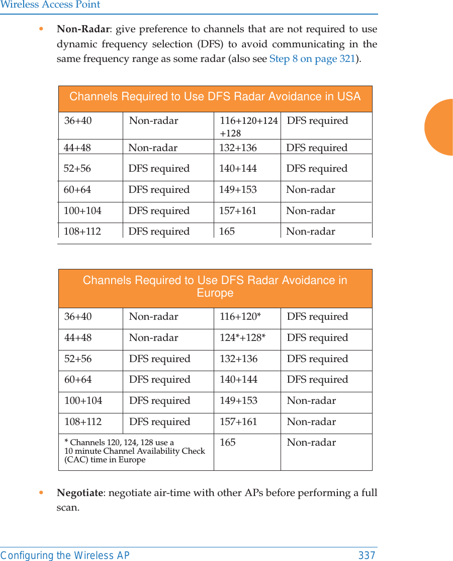
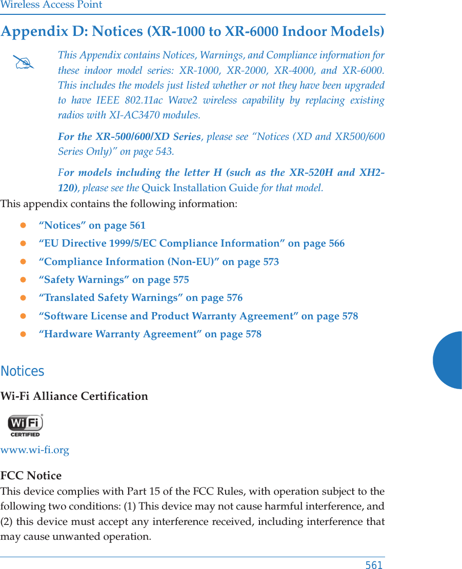
![Wireless Access Point364 Configuring the Wireless AP•Full Scan: perform a full traffic scan on all channels on all IAPs to determine the best channel allocation.•Non-Radar: give preference to channels without radar-detect. See table in “Procedure for Configuring Global 802.11an IAP Settings” on page 335. •Include WDS: automatically assign 5GHz to WDS client links.Click Factory Defaults if you wish to instruct the AP to return all IAPs to their factory preset channels. APs do not use the same factory preset values for channel assignments. Instead, if the AP has been deployed for a while and already has data from the spectrum analyzer and Xirrus Roaming Protocol about channel usage on neighboring APs, it performs a quick auto channel using that information (without doing a full RF scan) to make an intelligent choice of channel assignments. If the AP has been rebooted and has no saved configuration or is just being deployed for the first time, it has no prior data about its RF environment. In this case, it will pick a set of compatible channel assignments at random. 15. Auto Channel Configuration Mode: This option allows you to instruct the AP to auto-configure channel selection for each enabled IAP when the AP is powered up. Choose On AP PowerUp to enable this feature, or choose Disabled to disable this feature.16. Auto Channel Configure on Time: This option allows you to instruct the AP to auto-configure channel selection for each enabled IAP at a time you specify here. Leave this field blank unless you want to specify a time at which the auto-configuration utility is initiated. Time is specified in hours and minutes, using the format: [day]hh:mm [am|pm]. If you omit the optional day specification, channel configuration will run daily at the #On XR-500/600 and XR-1000 Series models, the Factory Defaults button will not restore iap1 to monitor mode. You will need to restore this setting manually. Also, you may need to set RF Monitor Mode to Timeshare Mode again - see “RF Monitor” on page 359.](https://usermanual.wiki/Cambium-Networks/XR620.User-Manual/User-Guide-3002682-Page-390.png)

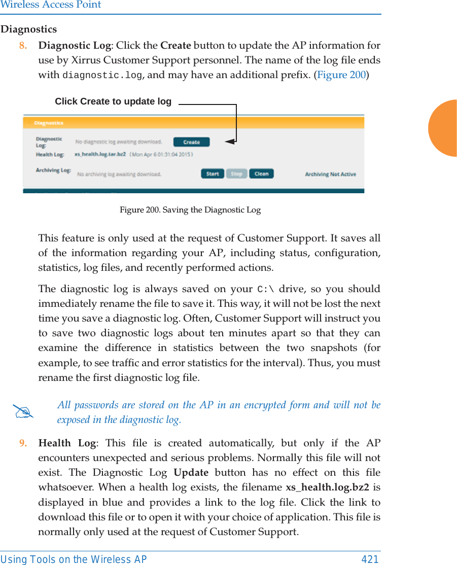
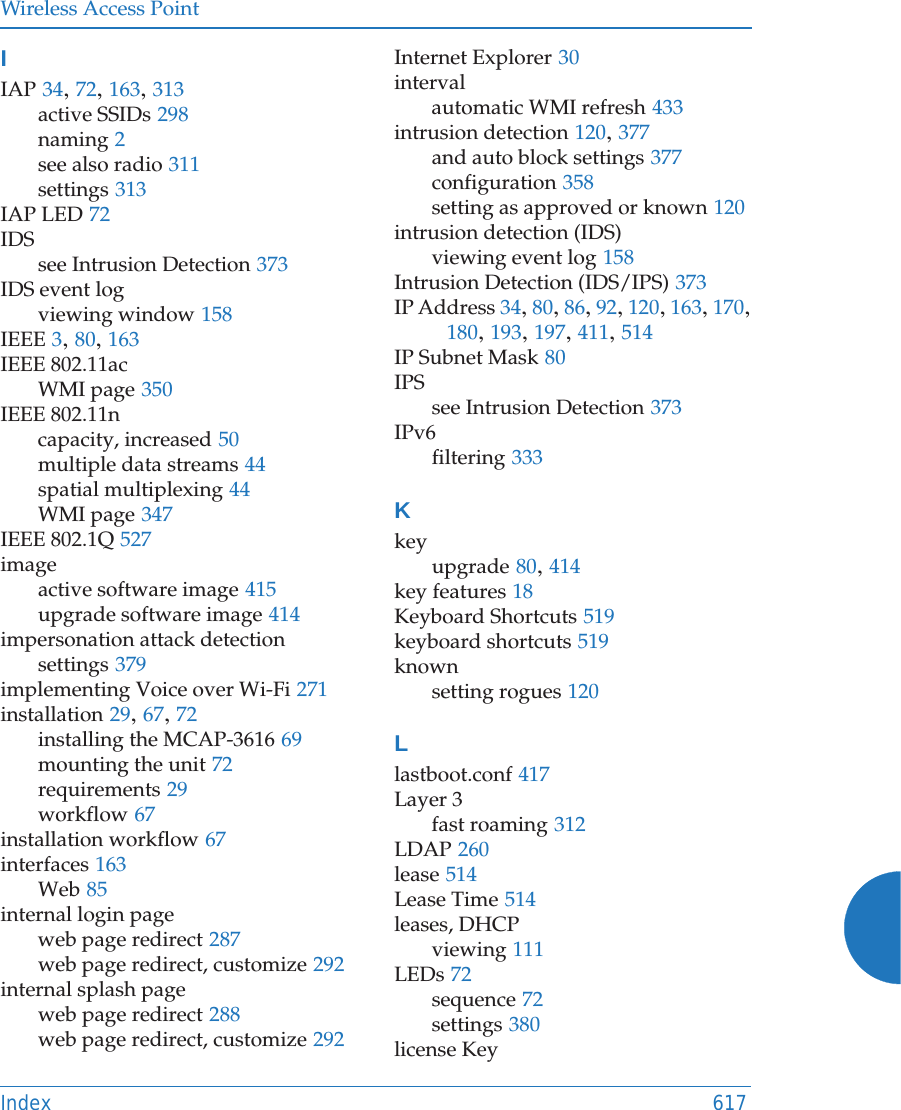
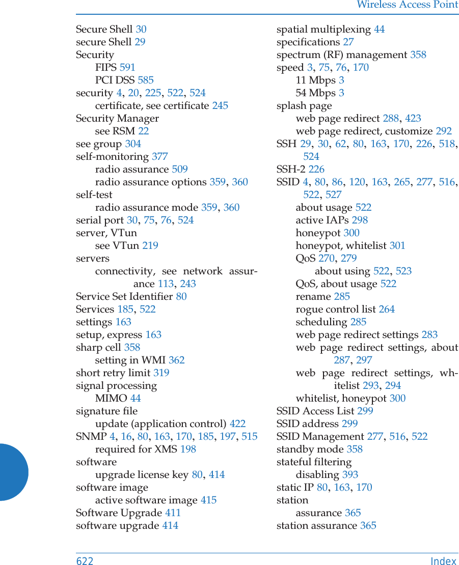
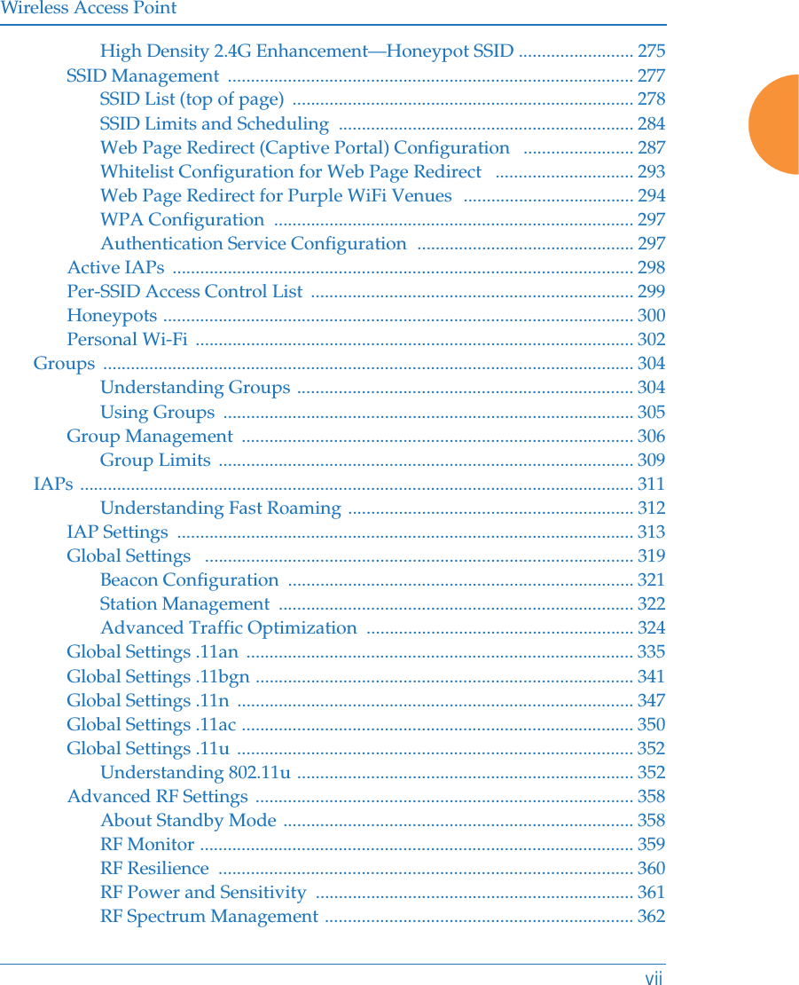
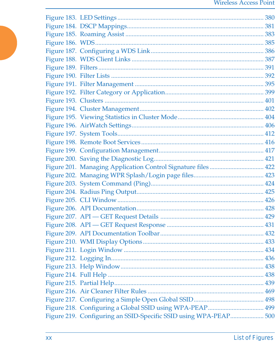
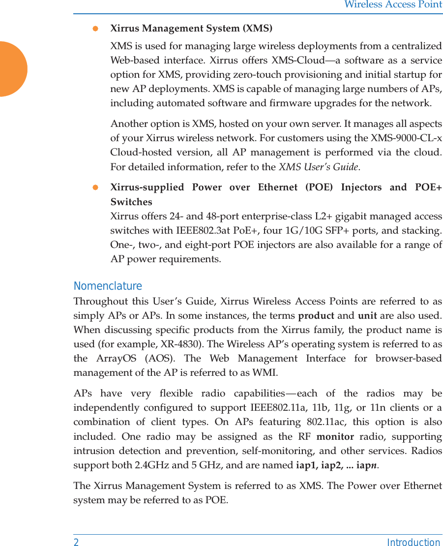
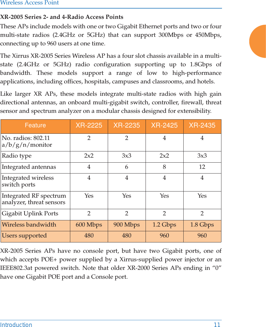
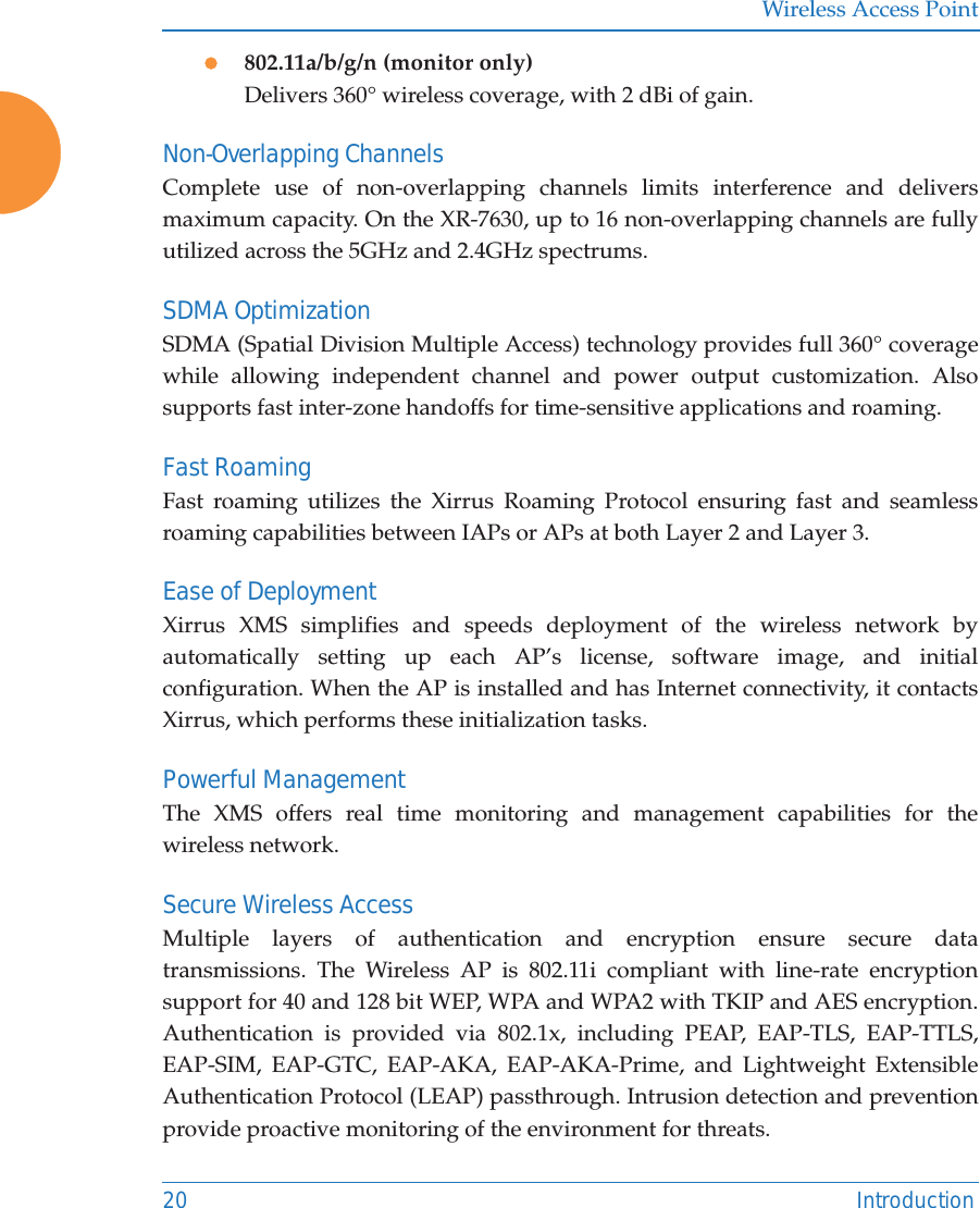
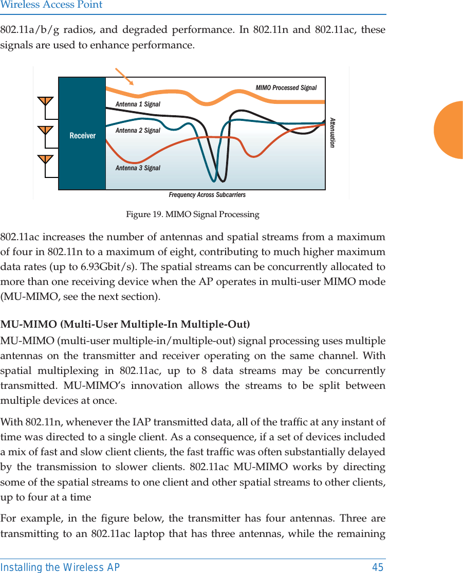
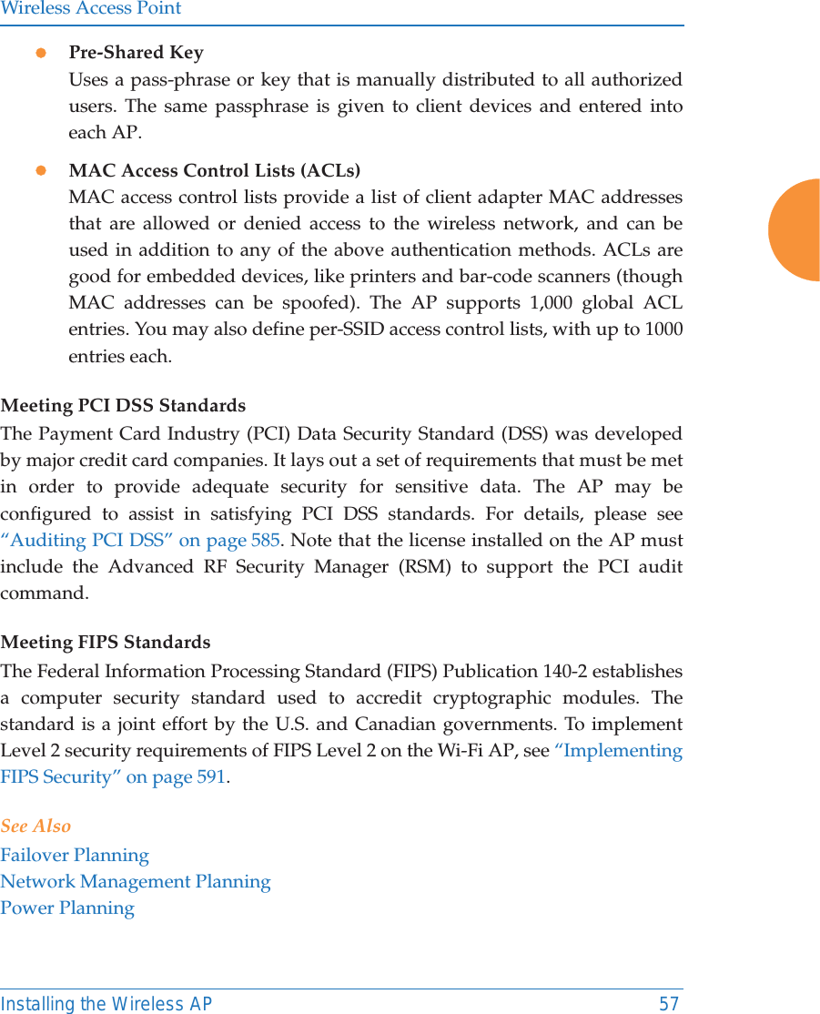
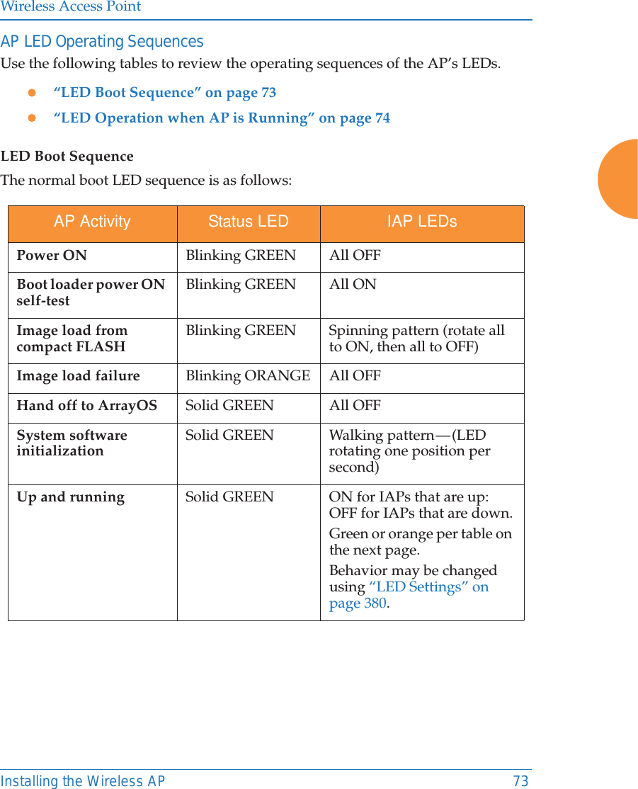
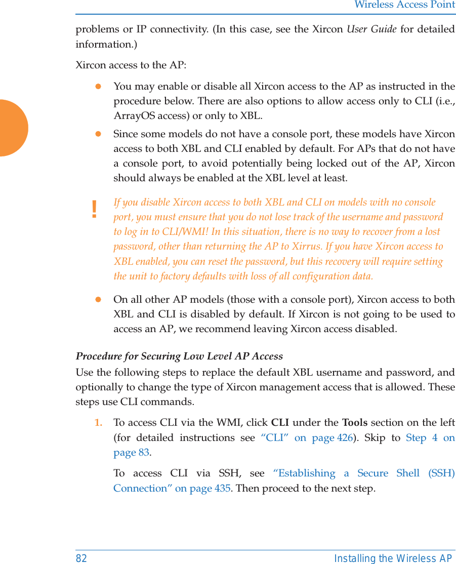
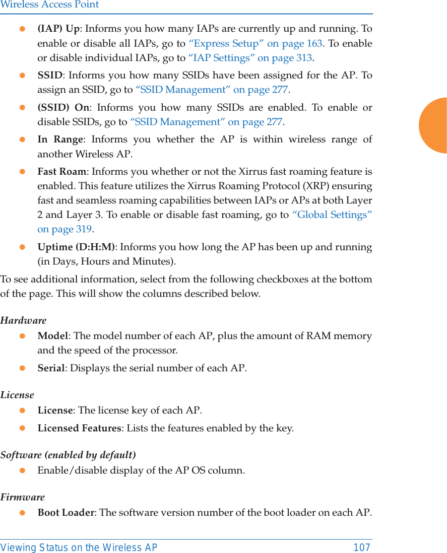
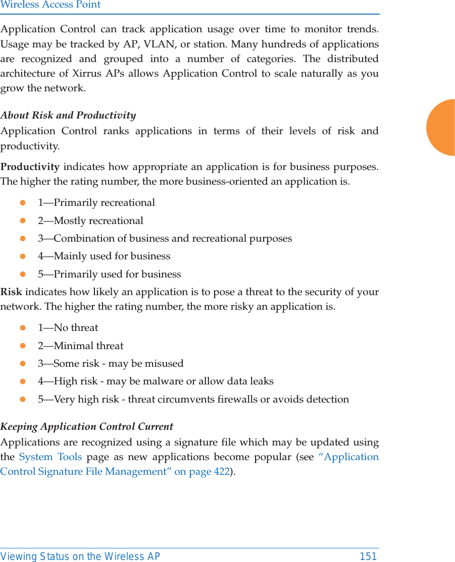
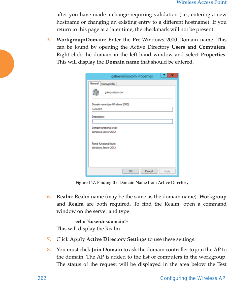
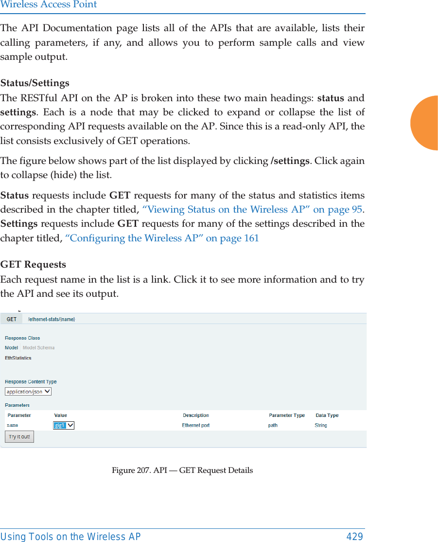
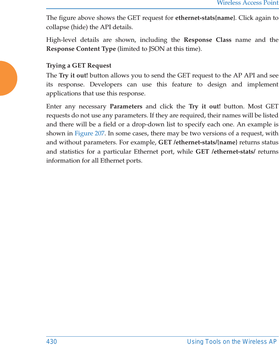
![Wireless Access Point428 Using Tools on the Wireless APAPI DocumentationAPs provide an API interface conforming to the RESTful API model. Developers may use this read-only API to read status, statistics, and settings from the AP. The interactive API Documentation page provides documentation for the API. You may use the AP’s API for purposes such as integrating with third party applications or creating your own applications for network monitoring and analysis. Using the RESTful API eliminates the need to use CLI scripting, or to use SNMP which can be cumbersome for polling large amounts of data. Results are returned in JavaScript Object Notation (JSON) format, a text-based open standard designed for human-readable data interchange. The API documentation is tightly integrated with the server code. The API Documentation page allows you to interact with the API in a sandbox UI that gives clear insight into how the API responds to parameters and options. Security for the API is provided with OAuth, as described in “OAuth 2.0 Management” on page 265. Once registration is completed and a permanent token for this AP has been obtained, your application may access the RESTful API using the client_id and the token at the following URL: https://[AP hostname or IP address]/api/v3/[api-name] Figure 206. API Documentation](https://usermanual.wiki/Cambium-Networks/XR620.User-Manual/User-Guide-3002682-Page-454.png)
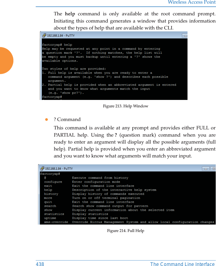
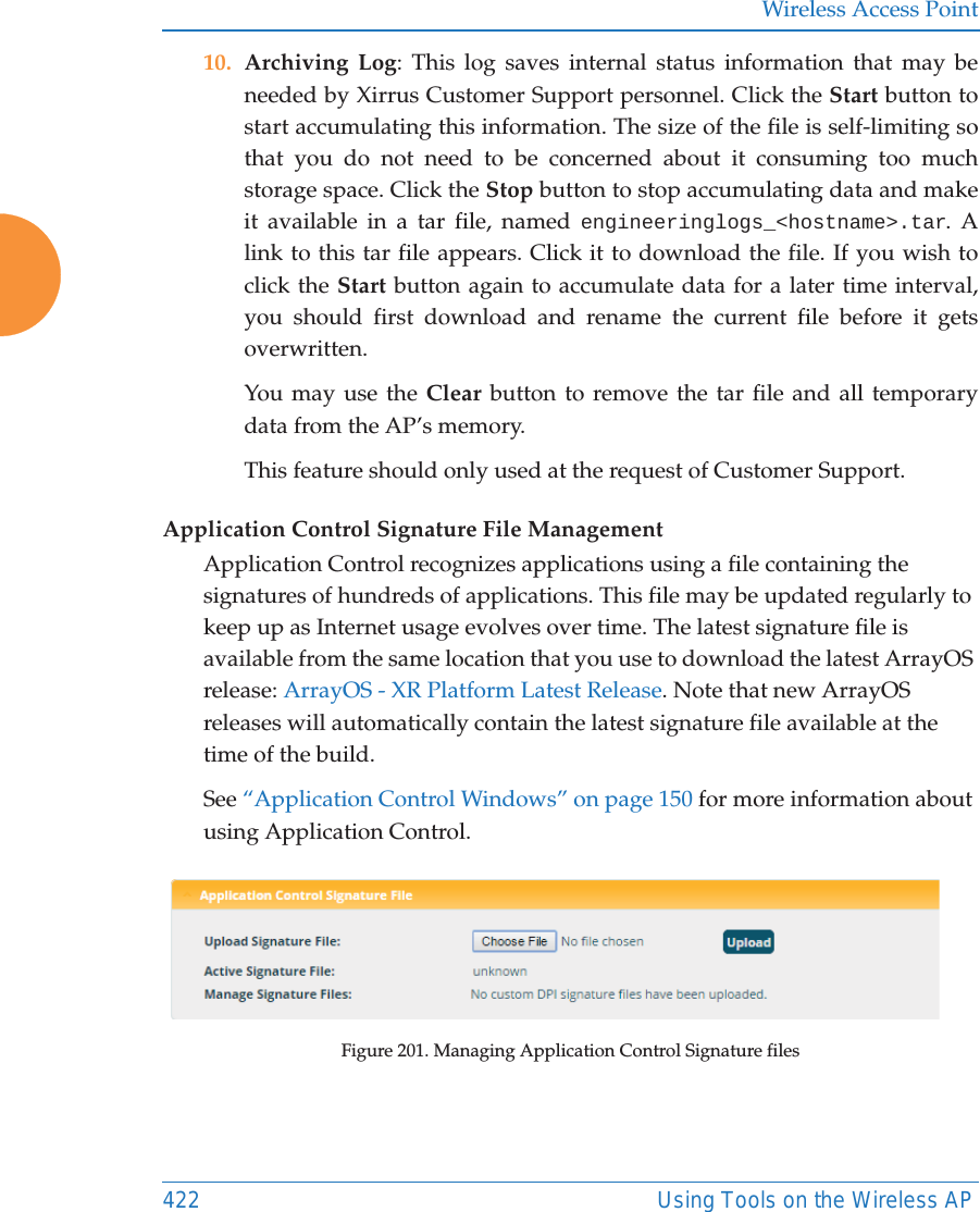
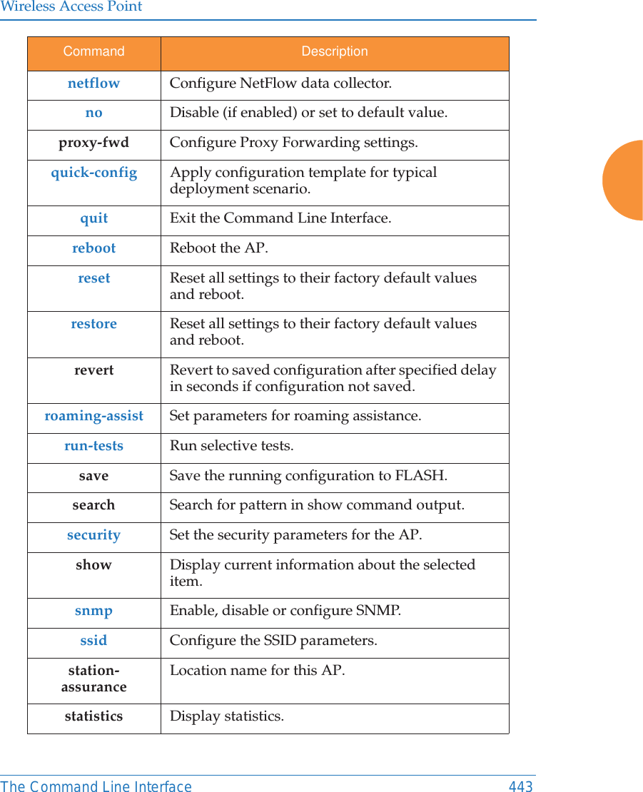
![Wireless Access Point440 The Command Line InterfaceTop Level CommandsThis section offers an at-a-glance view of all top level commands — organized alphabetically. Top level commands are defined here as commands that are directly accessible from the root command prompt that consists of the name of the AP followed by a “#” sign (e.g. MyAP#). When inputting commands, be aware that all commands are case-sensitive.All other commands are considered second level configuration commands — these are the commands you use to configure specific elements of the AP’s features and functionality. For a listing of these commands with examples of command formats and structure, go to “Configuration Commands” on page 452.Root Command PromptThe following table shows the top level commands that are available from the root command prompt [MyAP]. Command Description@ Type @n to execute command n (as shown by the history command).configure Enter the configuration mode. See “Configuration Commands” on page 452. exit Exit the CLI and terminate your session — if this command is used at any level other than the root command prompt you will simply exit the current level (step back) and return to the previous level.help Show a description of the interactive help system. See also, “Getting Help” on page 437. history List history of commands that have been executed.more Turn terminal pagination ON or OFF.quit Exit the Command Line Interface (from any level).search Search for pattern in show command output.](https://usermanual.wiki/Cambium-Networks/XR620.User-Manual/User-Guide-3002682-Page-466.png)
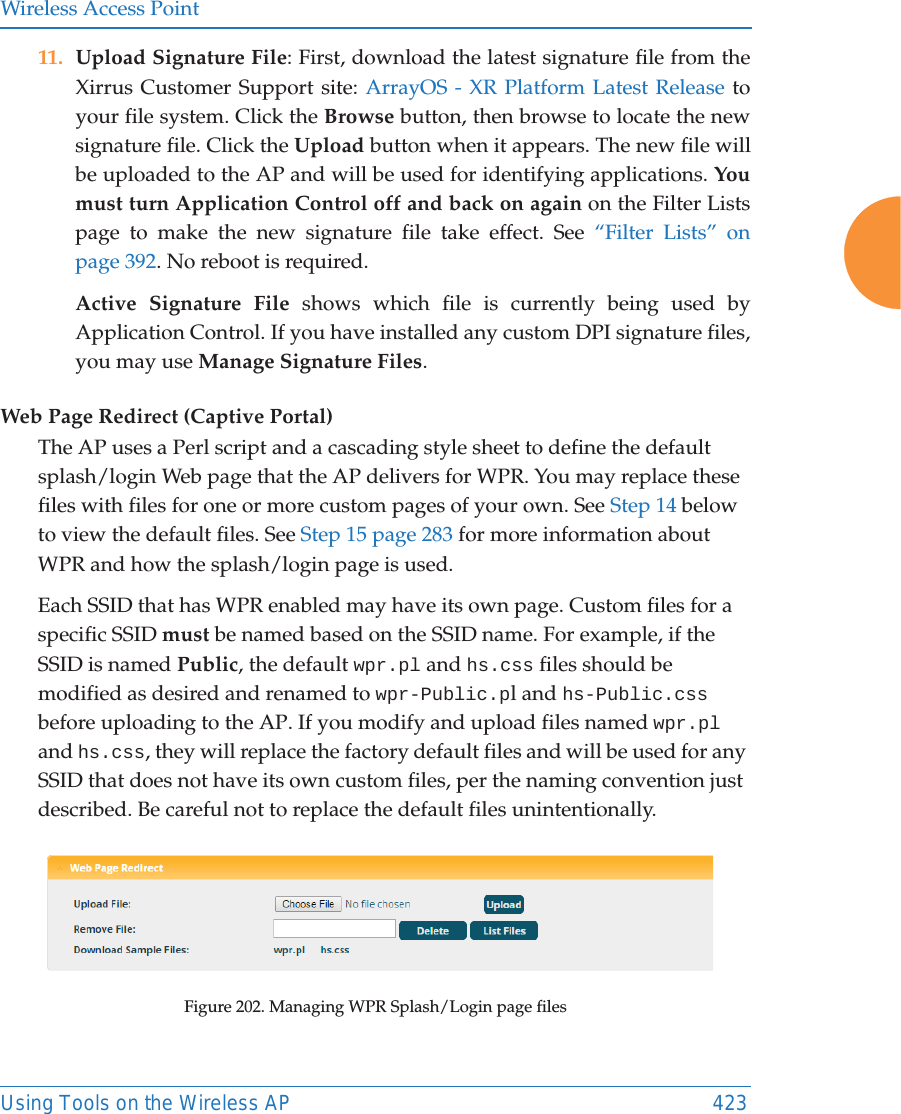
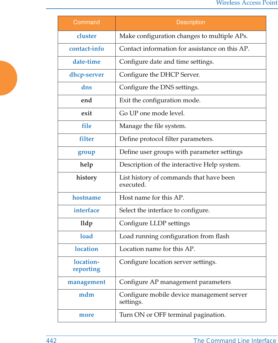
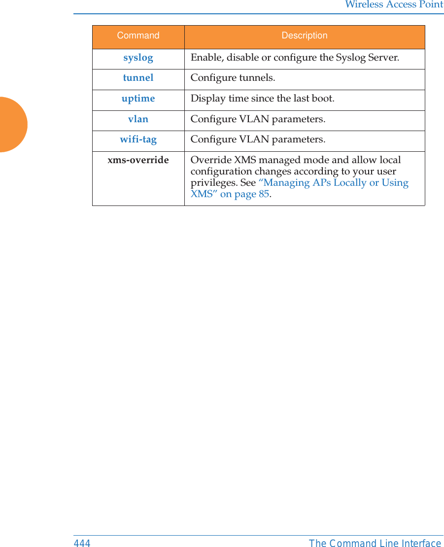
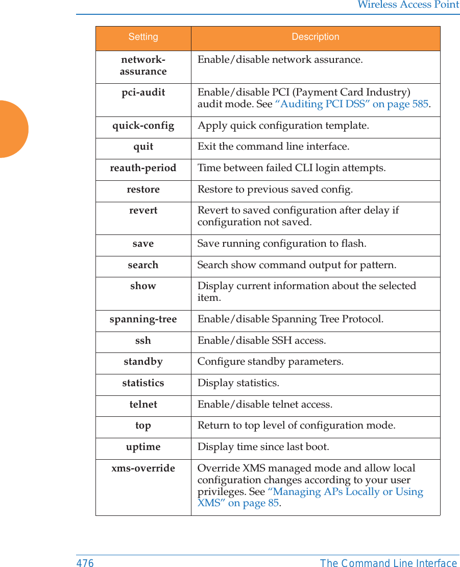
![Wireless Access PointThe Command Line Interface 441configure CommandsThe following table shows the second level commands that are available with the top level configure command [MyAP(config)#]. show Display information about the selected item. See “show Commands” on page 445. statistics Display statistical data about the AP. See “statistics Commands” on page 450. uptime Display the elapsed time since the last boot.xms-override Override XMS managed mode and allow local configuration changes according to your user privileges. See “Managing APs Locally or Using XMS” on page 85.Command Description@ Type @n to execute command n (as shown by the history command).acl Configure the Access Control List.activation Start or stop activation server pollingadmin Define administrator access parameters.auth Configure Oauth tokens. authentication-serverConfigure authentication server parametersboot-env Display or modify boot loader environment variables. cdp Configure Cisco Discovery Protocol settings. clear Remove/clear the requested elements.Command Description](https://usermanual.wiki/Cambium-Networks/XR620.User-Manual/User-Guide-3002682-Page-467.png)
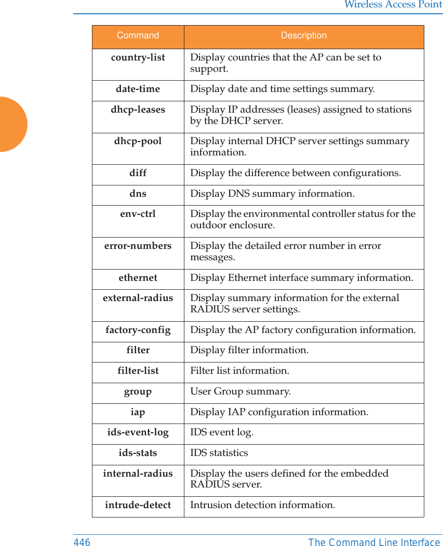
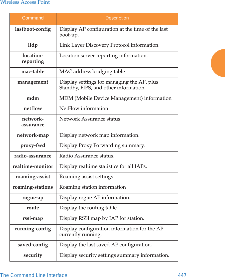
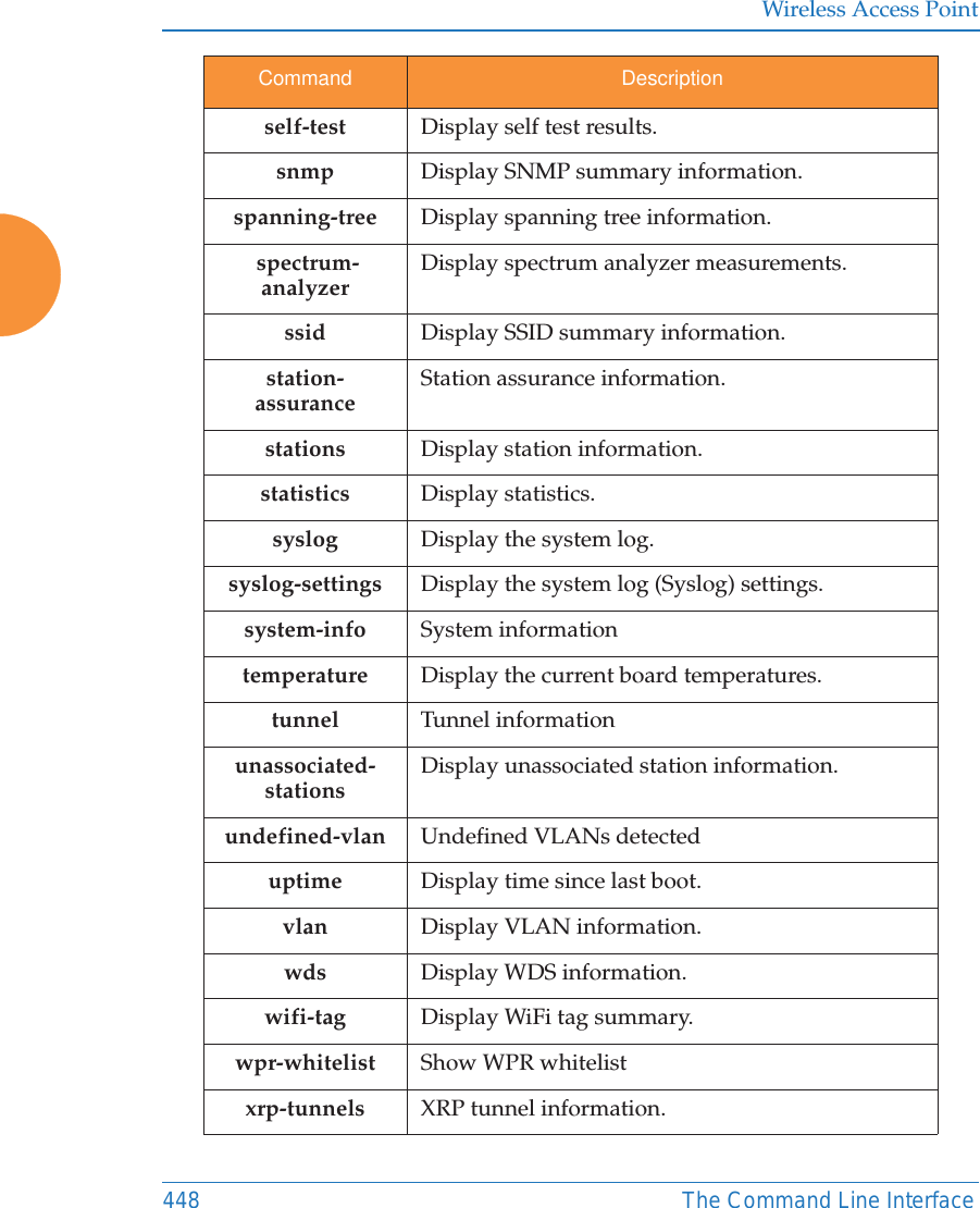
![Wireless Access PointThe Command Line Interface 445show CommandsThe following table shows the second level commands that are available with the top level show command [MyAP# show].Command Descriptionacl Display the Access Control List.active-directory Show Active Directory information.admin Display the administrator list or login information.applications Application statistics.arp ARP table information.associated-stationsDisplay stations that have associated to the AP.auth Show Open Authentication tokens.authentication-serverAuthentication server settings summary.bond Bond informationboot-env Display Boot loader environment variables. capabilities Display detailed station capabilities. cdp Display Cisco Discovery Protocol settings.channel-list Display list of AP’s 802.11an and bgn channels. cluster Display Cluster summary.clear-text Display and enter passwords and secrets in the clear. conntrack Display the Connection Tracking table. console Display terminal settings.contact-info Display contact information.](https://usermanual.wiki/Cambium-Networks/XR620.User-Manual/User-Guide-3002682-Page-471.png)
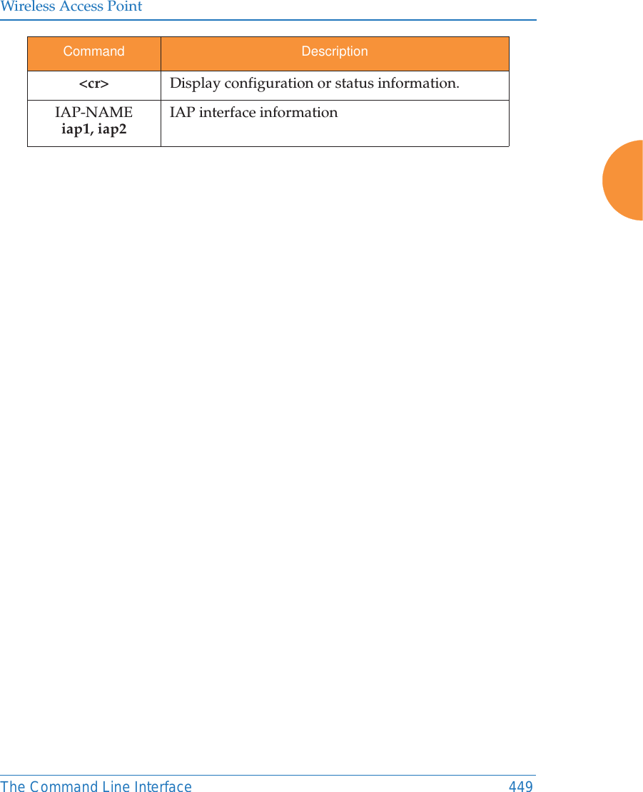
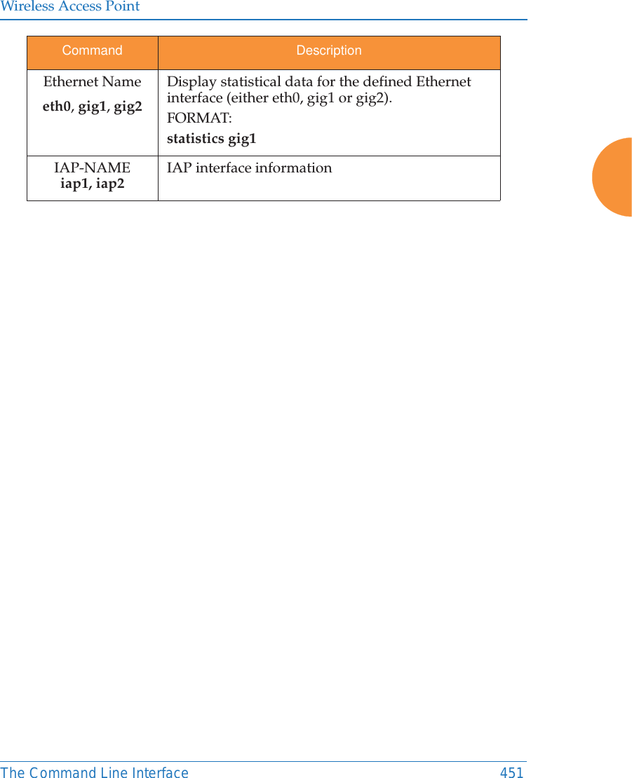
![Wireless Access Point450 The Command Line Interfacestatistics CommandsThe following table shows the second level commands that are available with the top level statistics command [MyAP# statistics].Command Descriptionethernet Display statistical data for all Ethernet interfaces. filter Display statistics for defined filters (if any).FORMAT:statistics filter [detail] filter-list Display statistics for defined filter list (if any).FORMAT:statistics filter <filter-list> iap Display statistical data for the defined IAP.FORMAT:statistics iap iap2station Display statistical data about associated stations.FORMAT:statistics station billwvlan Display statistical data for the defined VLAN. You must use the VLAN number (not its name) when defining a VLAN.FORMAT:statistics vlan 1wds Display statistical data for the defined active WDS (Wireless Distribution System) links.FORMAT:statistics wds 1<cr> Display configuration or status information.](https://usermanual.wiki/Cambium-Networks/XR620.User-Manual/User-Guide-3002682-Page-476.png)
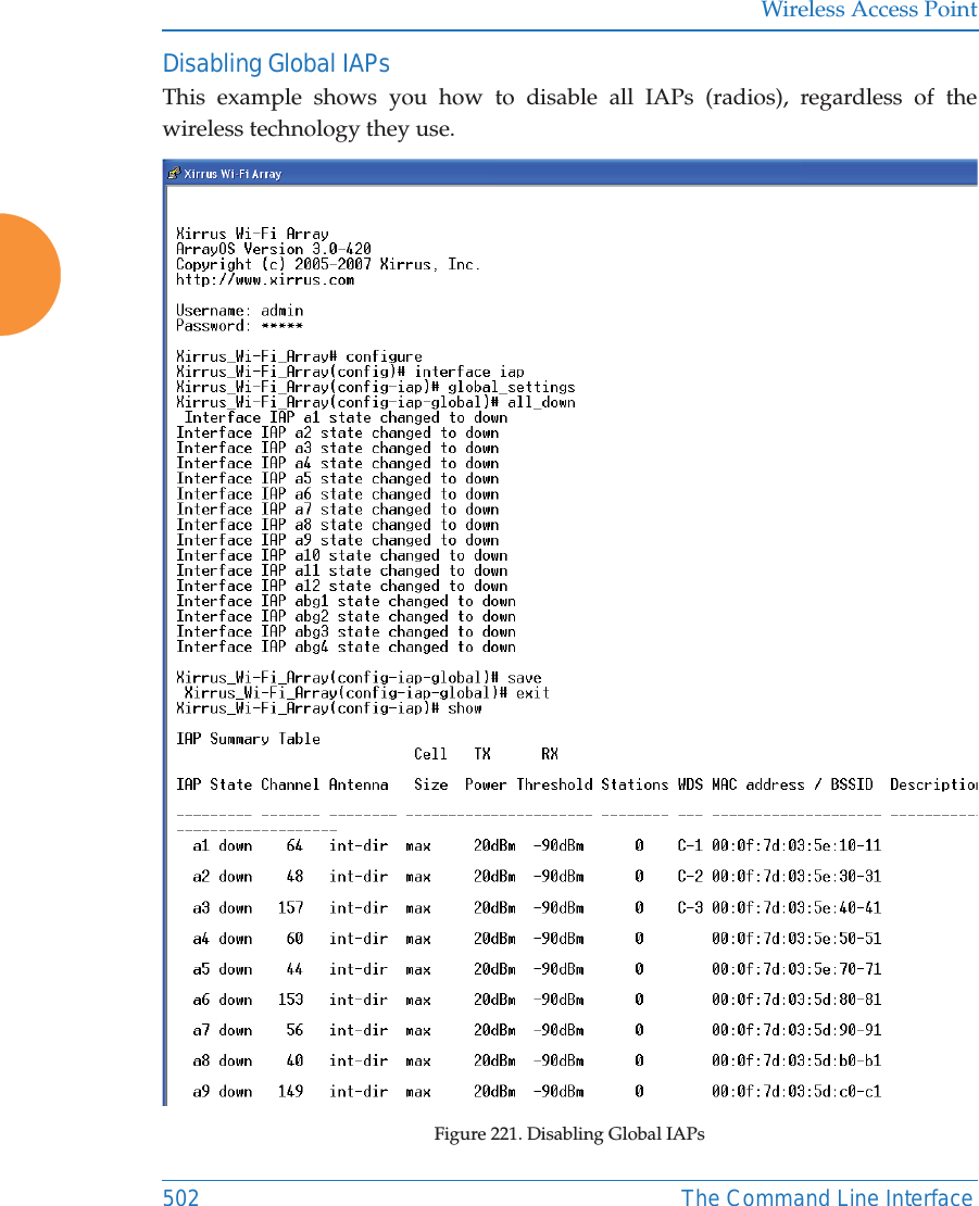
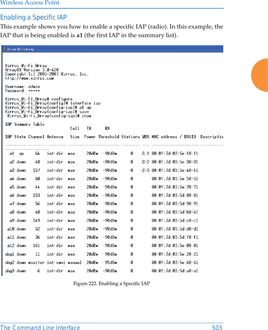
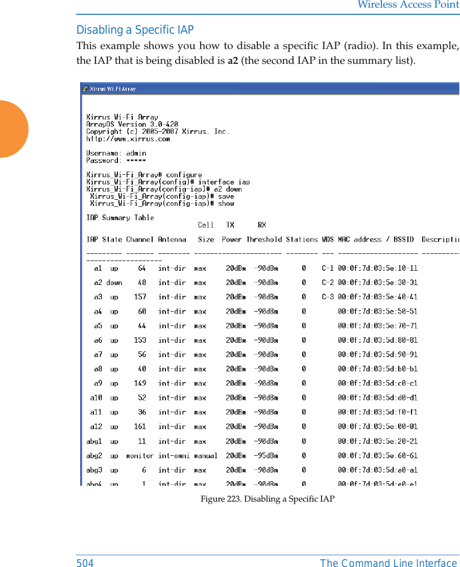
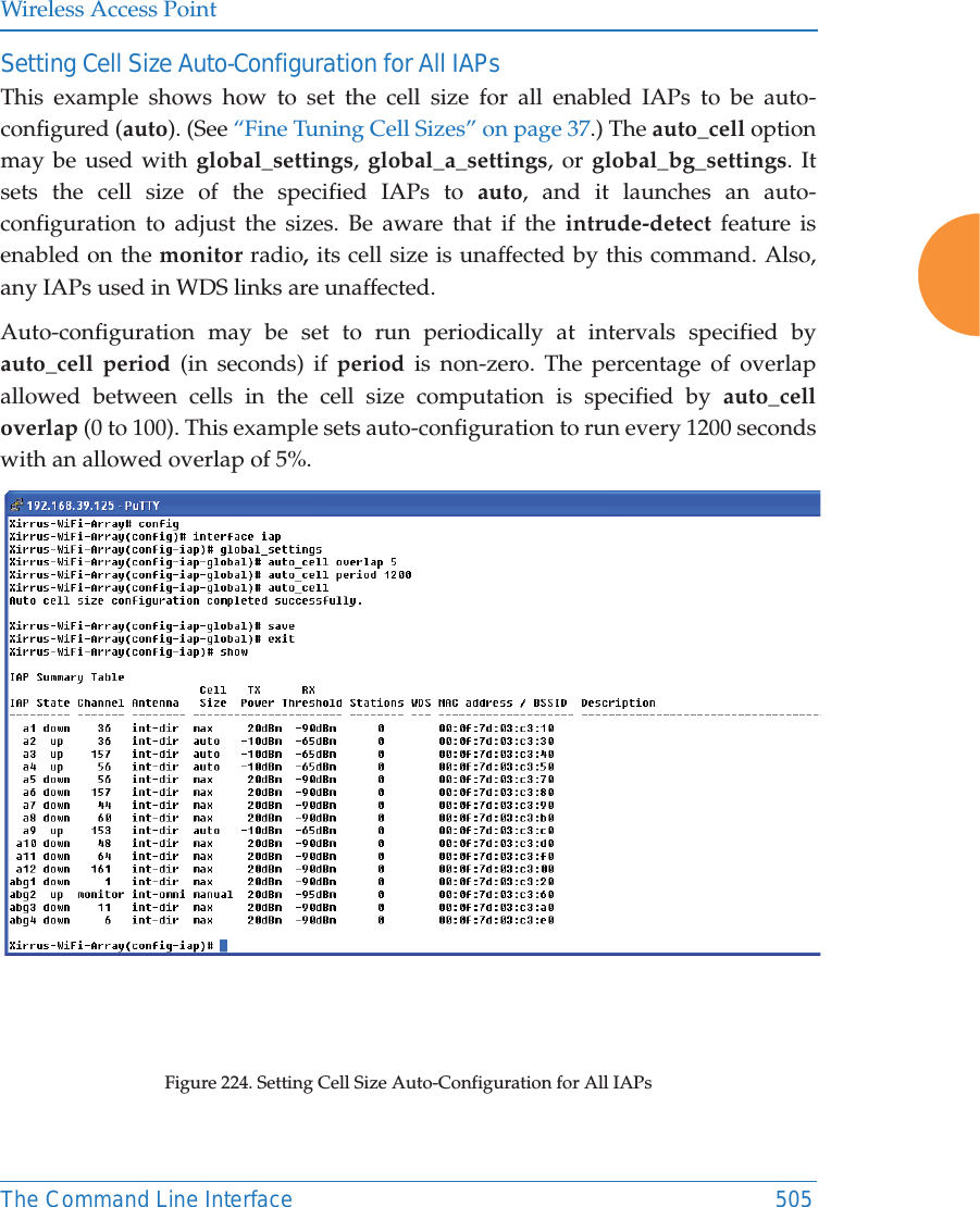
![Wireless Access Point452 The Command Line InterfaceConfiguration CommandsAll configuration commands are accessed by using the configure command at the root command prompt (MyAP#). This section provides a brief description of each command and presents sample formats where deemed necessary. The commands are organized alphabetically. When inputting commands, be aware that all commands are case-sensitive.To see examples of some of the key configuration tasks and their associated commands, go to “Sample Configuration Tasks” on page 497.acl The acl command [MyAP(config)# acl] is used to configure the Access Control List.Command Descriptionadd Add a MAC address to the list.FORMAT:acl add AA:BB:CC:DD:EE:FFdel Delete a MAC address from the list.FORMAT:acl del AA:BB:CC:DD:EE:FFdisable Disable the Access Control ListFORMAT:acl disableenable Enable the Access Control ListFORMAT:acl enablereset Delete all MAC addresses from the list.FORMAT:acl reset](https://usermanual.wiki/Cambium-Networks/XR620.User-Manual/User-Guide-3002682-Page-478.png)
![Wireless Access PointThe Command Line Interface 453admin The admin command [MyAP(config-admin)#] is used to configure the Administrator List.Command Descriptionadd Add a user to the Administrator List.FORMAT:admin add [userID]del Delete a user to the Administrator List.FORMAT:admin del [userID]edit Modify user in the Administrator List.FORMAT:admin edit [userID]privilege-name Define administrator privilege level namesprivilege-section Define administrator privilege level required by config section.radius Define a RADIUS server to be used for authenticating administrators.FORMAT:admin radius [disable | enable | off | on | timeout <seconds> | auth-type [PAP | CHAP]] admin radius [primary |secondary] port <portid> server [<ip-addr> | <host>] secret <shared-secret>reset Delete all users and restore the default user.FORMAT:admin reset](https://usermanual.wiki/Cambium-Networks/XR620.User-Manual/User-Guide-3002682-Page-479.png)
![Wireless Access Point454 The Command Line InterfaceauthThe auth command [MyAP(config)# auth] is used to configure Oauth tokens. See also, “OAuth 2.0 Management” on page 265. cdp The cdp command [MyAP(config)# cdp] is used to configure the Cisco Discovery Protocol.Command Descriptiondel Delete an Oauth token.FORMAT:auth del <Oauth token>reset Delete all Oauth tokens.FORMAT:auth resetCommand Descriptiondisable Disable the Cisco Discovery ProtocolFORMAT:cdp disableenable Enable the Cisco Discovery ProtocolFORMAT:cdp enablehold-time Select CDP message hold time before messages received from neighbors expire.FORMAT:cdp hold-time [# seconds]](https://usermanual.wiki/Cambium-Networks/XR620.User-Manual/User-Guide-3002682-Page-480.png)
![Wireless Access PointThe Command Line Interface 455interval The AP sends out CDP announcements at this interval. FORMAT:cdp interval [# seconds] off Disable the Cisco Discovery ProtocolFORMAT:cdp offon Enable the Cisco Discovery ProtocolFORMAT:cdp onCommand Description](https://usermanual.wiki/Cambium-Networks/XR620.User-Manual/User-Guide-3002682-Page-481.png)
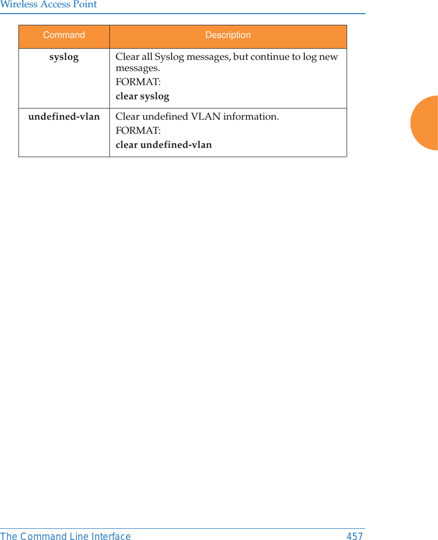
![Wireless Access Point456 The Command Line Interfaceclear The clear command [MyAP(config)# clear] is used to clear requested elements.Command Descriptionarp Clear the arp table entry for a requested IP address, or clear all entries if no IP address is entered.FORMAT:clear arp [ipaddress]authentication Deauthenticate a station (specified by MAC address, hostname, or IP address). If you specify the permanent option, then the station is deauthenticated and put on the access control list.FORMAT:clear authentication [permanent] [authenticated station]history Clear the history of CLI commands executed.FORMAT:clear history screen Clear the screen where you’re viewing CLI output.FORMAT:clear screenstation-assuranceClear all station assurance data, but continue to collect new data.FORMAT:clear station-assurancestatistics Clear the statistics for thee change, but it won’t show up requested element.FORMAT:clear statistics [ethname | all-eth | applications | filters |iap | station | vlan | wds]](https://usermanual.wiki/Cambium-Networks/XR620.User-Manual/User-Guide-3002682-Page-482.png)
![Wireless Access Point458 The Command Line InterfaceclusterThe cluster command [MYAP(config)# cluster] is used to create and operate clusters. Clusters allow you to configure multiple APs at the same time. Using CLI (or WMI), you may define a set of APs that are members of the cluster. Then you may switch the AP to Cluster operating mode for a selected cluster, which sends all successive configuration commands issued via CLI or WMI to all of the member APs. When you exit cluster mode, configuration commands revert to applying only to the AP to which you are connected.For more information, see “Clusters” on page 401. Command Descriptionadd Create a new AP cluster. Enters edit mode for that cluster to allow you to specify the APs that belong to the cluster.FORMAT:cluster add [cluster-name]del Delete an AP cluster. Type del? to list the existing clusters.FORMAT:cluster del [cluster-name]edit Enter edit mode for selected cluster to add or delete APs that belong to the cluster.FORMAT:cluster edit [cluster-name]operate Enter Cluster operation mode. All configuration commands are applied to all of the selected cluster’s member APs until you give the end command (see above). FORMAT:cluster operate [cluster-name]reset Delete all clusters.FORMAT:cluster reset](https://usermanual.wiki/Cambium-Networks/XR620.User-Manual/User-Guide-3002682-Page-484.png)
![Wireless Access PointThe Command Line Interface 459contact-info The contact-info command [MyAP(config)# contact-info] is used for managing administrator contact information.Command Descriptionemail Add an email address for the contact (must be in quotation marks).FORMAT:contact-info email [“contact@mail.com”]name Add a contact name (must be in quotation marks).FORMAT:contact-info name [“Contact Name”]phone Add a telephone number for the contact (must be in quotation marks).FORMAT:contact-info phone [“8185550101”]](https://usermanual.wiki/Cambium-Networks/XR620.User-Manual/User-Guide-3002682-Page-485.png)
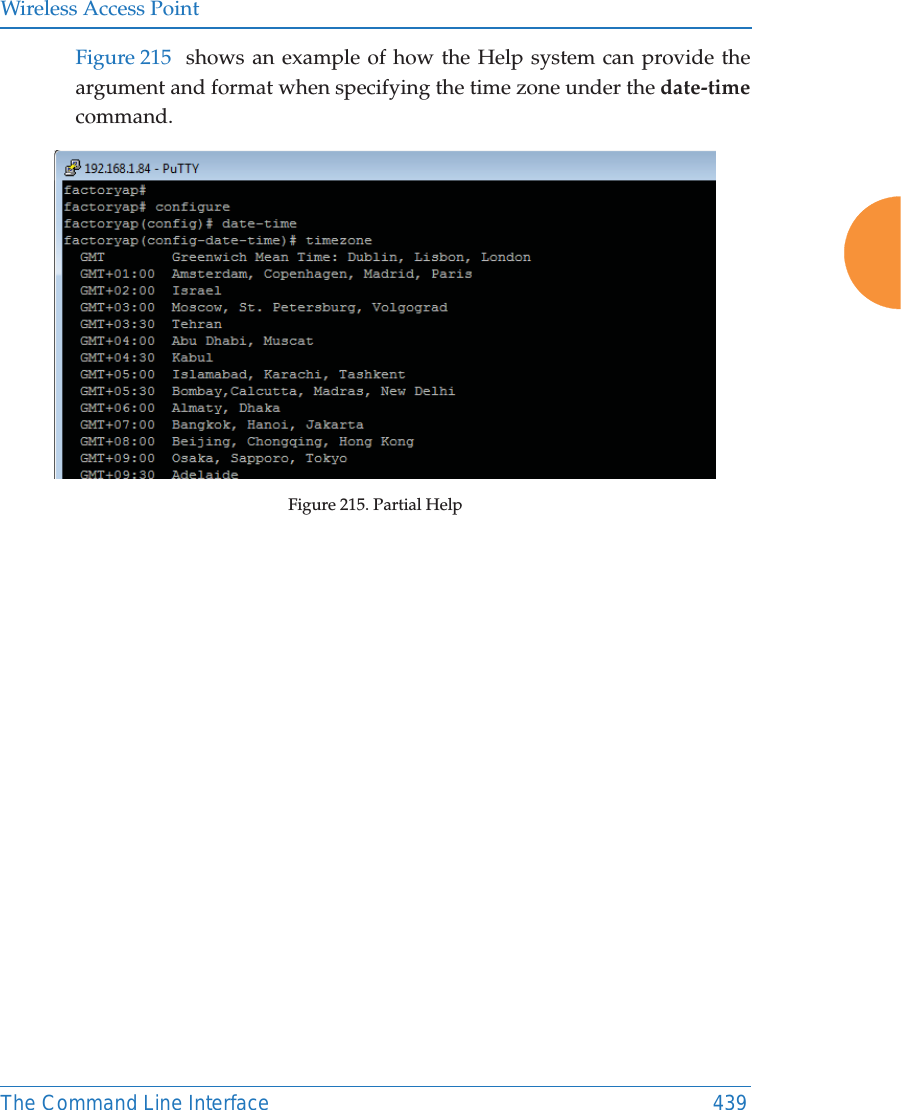
![Wireless Access Point460 The Command Line Interfacedate-time The date-time command [MyAP(config-date-time)#] is used to configure the date and time parameters. Your AP supports the Network Time Protocol (NTP) in order to ensure that the AP’s internal time is accurate. NTP is set to UTC time by default; however, you can set the time zone so that your AP will display local time. This is done by defining an offset from the UTC value. For example, Pacific Standard Time is 8 hours behind UTC time, so the offset from UTC time would be -8.Command Descriptiondst_adjust Enable adjustment for daylight savings.FORMAT:date-time dst_adjustno Disable daylight savings adjustment.FORMAT:date-time no dst_adjustntp Enable the NTP server.FORMAT:date-time ntp on (or off to disable)offset Set an offset from Greenwich Mean Time.FORMAT:date-time no dst_adjustset Set the date and time for the AP.FORMAT:date-time set [10:24 10/23/2007]timezone Configure the time zone.FORMAT:date-time timezone [-8]](https://usermanual.wiki/Cambium-Networks/XR620.User-Manual/User-Guide-3002682-Page-486.png)
![Wireless Access PointThe Command Line Interface 461dhcp-server The dhcp-server command [MyAP(config-dhcp-server)#] is used to add, delete and modify DHCP pools.Command Descriptionadd Add a DHCP pool.FORMAT:dhcp-server add [dhcp pool]del Delete a DHCP pool.FORMAT:dhcp-server del [dhcp pool]edit Edit a DHCP poolFORMAT:dhcp-server edit [dhcp pool]reset Delete all DHCP pools.FORMAT:dhcp-server reset](https://usermanual.wiki/Cambium-Networks/XR620.User-Manual/User-Guide-3002682-Page-487.png)
![Wireless Access Point462 The Command Line Interfacedns The dns command [MyAP(config-dns)#] is used to configure your DNS parameters.Command Descriptiondomain Enter your domain name.FORMAT:dns domain [www.mydomain.com]server1 Enter the IP address of the primary DNS server.FORMAT:dns server1 [1.2.3.4]server2 Enter the IP address of the secondary DNS server.FORMAT:dns server1 [2.3.4.5]server3 Enter the IP address of the tertiary DNS server.FORMAT:dns server1 [3.4.5.6]use-dhcp Enable or disable updates to DNS settings via DHCP.FORMAT:dns use-dhcp [off | on]](https://usermanual.wiki/Cambium-Networks/XR620.User-Manual/User-Guide-3002682-Page-488.png)
![Wireless Access PointThe Command Line Interface 463file The file command [MyAP(config-file)#] is used to manage files.Command Descriptionactive-image Validate and commit a new AP software image. backup-image Validate and commit a new backup software image. cat List file contents.check-image Validate a new AP software image. chkdsk Check flash file system.copycpCopy a file to another file.FORMAT:file copy [sourcefile destinationfile]create-text Create a text file on the flash file system, <EOF> to finish.dir List the contents of a directory.FORMAT:file dir [directory]erase Delete a file from the FLASH file system.FORMAT:file erase [filename]format Format flash file system.ftp Open an FTP connection with a remote server. Files will be transferred in binary mode. FORMAT:file ftp host {<hostname> |<ip>} [port <port_#>] [user {anonymous | <username> password <passwd> } ] { put <source_file> [<dest_file>] | get <source_file> [<dest_file>] }Note: Any time you transfer any kind of software image file for the AP, it must be transferred in binary mode, or the file may be corrupted.](https://usermanual.wiki/Cambium-Networks/XR620.User-Manual/User-Guide-3002682-Page-489.png)
![Wireless Access Point464 The Command Line Interfacehttp-get Perform an HTTP file download. This is the preferred method of downloading files for XMS Cloud. FORMAT:http-get [no-cert-check] <url> [<local_file>]no-cert-check causes the AP to download the file even if the SSL certificate is invalid, expired, or not signed by a recognized CA<url> is a standard HTTP URL, e.g. https://file.example.com:8080/mydir/myfile.ext.zhttp:// or https:// may be omitted, in which case HTTP is assumed<local_file> is an optional parameter that describes the path and name where the file should be savedzif no local_file is specified, the file will be saved in the root of the flash storagezthe local_file does support specifying a directory, which will be created if it doesn't already existlist List the contents of a file.FORMAT:file list [filename]mkdir Create a directory on the flash file system.mv Rename a file on the flash file system.Command Description](https://usermanual.wiki/Cambium-Networks/XR620.User-Manual/User-Guide-3002682-Page-490.png)
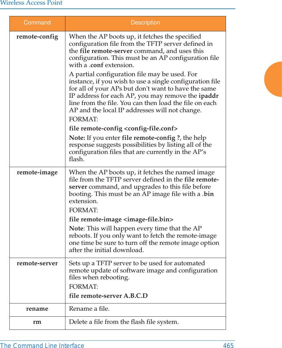
![Wireless Access Point466 The Command Line Interfacermdir Delete a directory on the flash file system.scp Copy a file to or from a remote system. You may specify the port to use.tftp Open a TFTP connection with a remote server.FORMAT:file tftp host {<hostname> |<ip>} [port <port_#>] [user {anonymous | <username> password <passwd> } ] { put <source_file> [<dest_file>] | get <source_file> [<dest_file>] }Note: Any time you transfer any kind of software image file for the AP, it must be transferred in binary mode, or the file may be corrupted. Command Description](https://usermanual.wiki/Cambium-Networks/XR620.User-Manual/User-Guide-3002682-Page-492.png)
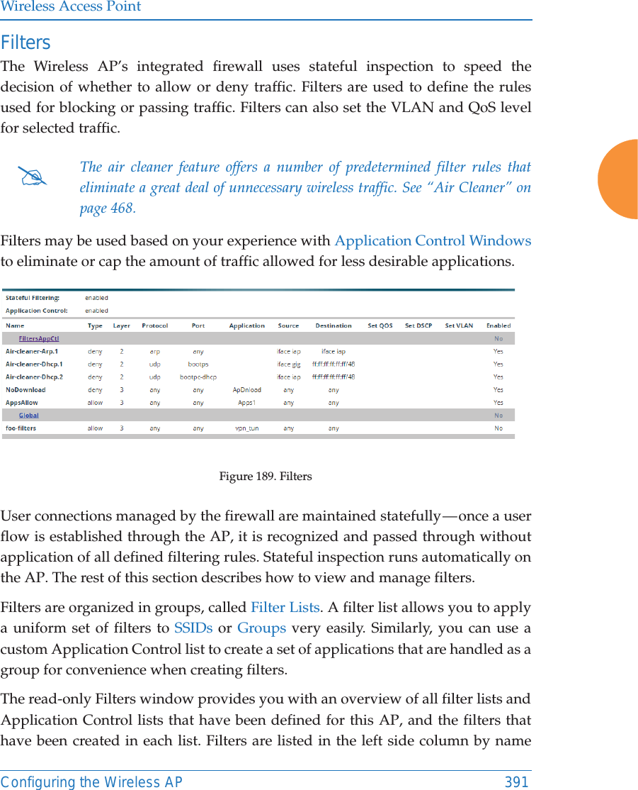
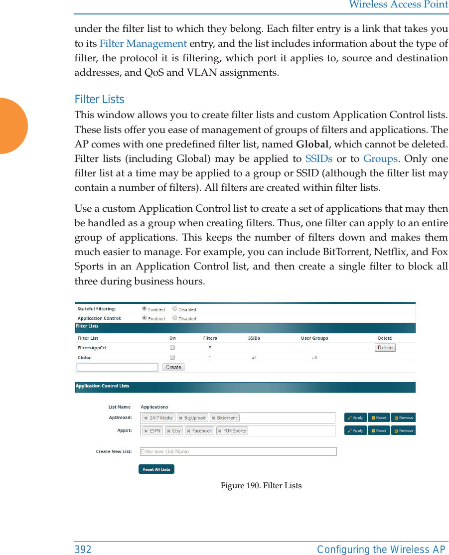
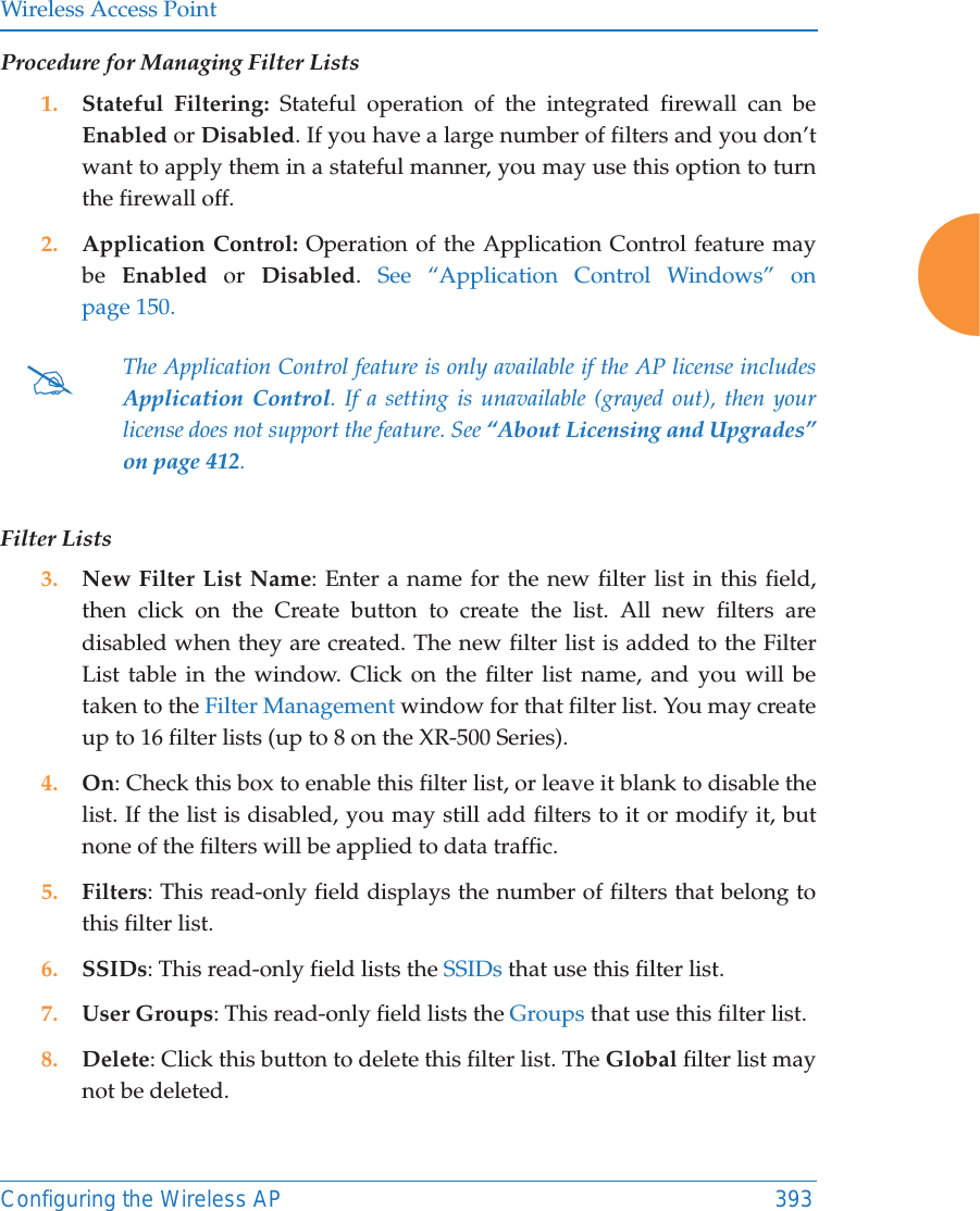
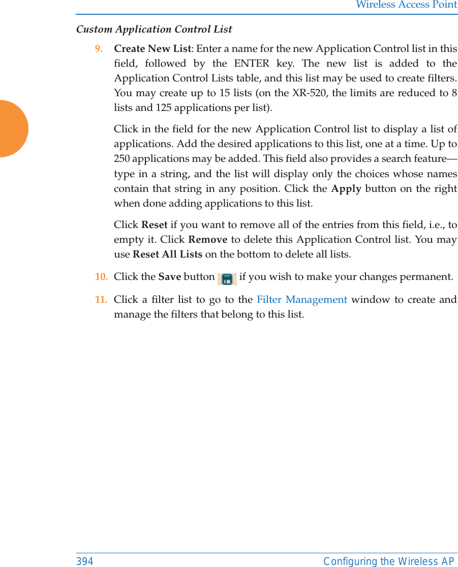
![Wireless Access PointThe Command Line Interface 467filter The filter command [MyAP(config-filter)#] is used to manage protocol filters and filter lists.Command Descriptionadd Add a filter. Details about the air cleaner feature are after the end of this table.FORMAT:filter add [air-cleaner |name]add-list Add a filter list.FORMAT:filter add-list [name]del Delete a filter.FORMAT:filter del [name]del-list Delete a filter list.FORMAT:filter del-list [name]edit Edit a filter.FORMAT:filter edit [name type]edit-list Edit a filter listFORMAT:filter edit-list [name type]enable Enable a filter list.FORMAT:filter enable move Change a filter priority.FORMAT:filter move [name priority]](https://usermanual.wiki/Cambium-Networks/XR620.User-Manual/User-Guide-3002682-Page-493.png)
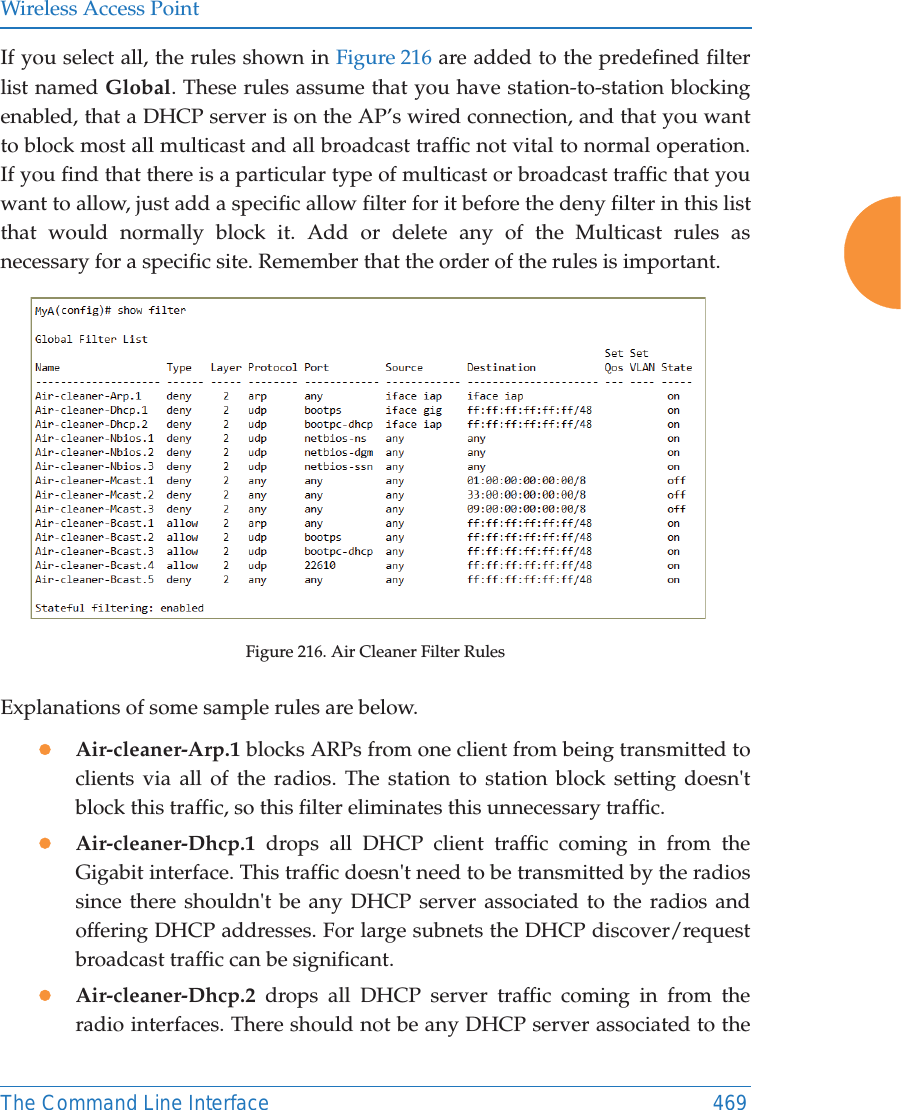
![Wireless Access Point468 The Command Line InterfaceAir CleanerThe air cleaner feature offers a number of predetermined filter rules that eliminate a great deal of unnecessary wireless traffic, resulting in improved performance. You may select all of the air cleaner rules for the greatest effect, or only specific rules, such as broadcast or multicast, to eliminate only a particular source of traffic. The following options are offered:MyAP(config)# filter add air-cleaner all All air cleaner filters arp Eliminate station to station ARPs over the air broadcast Eliminate broadcast traffic from the air dhcp Eliminate stations serving DHCP addresses from the air multicast Eliminate chatty multicast traffic from the air netbios Eliminate NetBIOS traffic from the airoff Disable a filter list.FORMAT:filter offon Enable a filter list.FORMAT:filter on reset Delete all protocol filters and filter lists.FORMAT:filter resetstateful Enable or disable stateful filtering (firewall).FORMAT:Stateful [enable | disable | on |off] track-apps Enable or disable application tracking.FORMAT:filter track-apps [enable | disable | on |off]Command Description](https://usermanual.wiki/Cambium-Networks/XR620.User-Manual/User-Guide-3002682-Page-494.png)
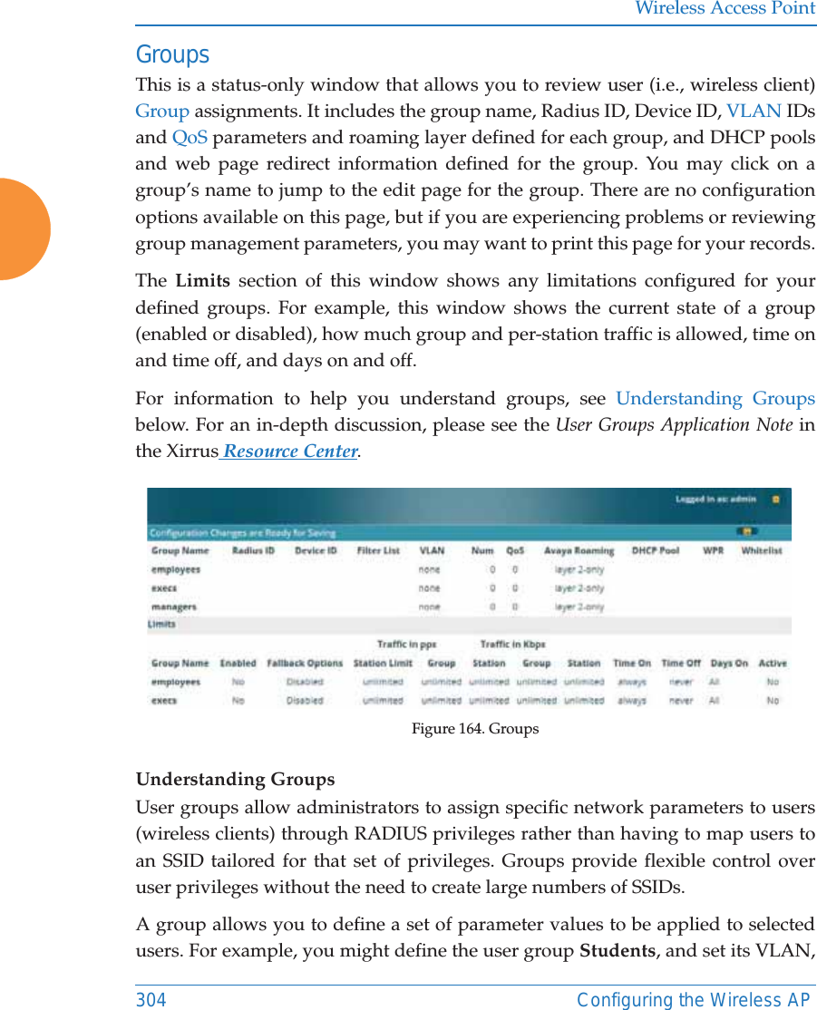
![Wireless Access PointThe Command Line Interface 471group The group command [MyAP(config)# group] is used to create and configure user groups. User groups allow administrators to assign specific network parameters to users through RADIUS privileges rather than having to map users to a specific SSID. Groups provide flexible control over user privileges without the need to create large numbers of SSIDs. For more information, see “Groups” on page 304. hostname The hostname command [MyAP(config)# hostname] is used to change the hostname used by the AP.Command Descriptionadd Create a new user group. FORMAT:group add [group-name]del Delete a user group.FORMAT:group del [group-name]edit Set parameters values for a group. FORMAT:group edit [group-name]reset Reset the group.FORMAT:group resetCommand Descriptionhostname Change the hostname of the AP.FORMAT:hostname [name]](https://usermanual.wiki/Cambium-Networks/XR620.User-Manual/User-Guide-3002682-Page-497.png)
![Wireless Access Point472 The Command Line Interfaceinterface The interface command [MyAP(config)# interface] is used to select the interface that you want to configure. To see a listing of the commands that are available for each interface, use the ? command at the selected interface prompt. For example, using the ? command at the MyAP(config-gig1}# prompt displays a listing of all commands for the gig1 interface.Command Descriptionbond1 Bond 1.bond2 Bond 2.console Select the console interface. The console interface is used for management purposes only.FORMAT:interface consolegig1 Select the Gigabit 1 interface.FORMAT:interface gig1gig2 Select the Gigabit 2 interface.FORMAT:interface gig2iap Select an IAP.FORMAT:interface iapIAP-NAMEiap1, iap2IAP interface information](https://usermanual.wiki/Cambium-Networks/XR620.User-Manual/User-Guide-3002682-Page-498.png)
![Wireless Access PointThe Command Line Interface 473load The load command [MyAP(config)# load] loads a configuration file.location The location command [MyAP(config)# location] is used to set the location descriptive string for the AP.Command Descriptionfactory.conf Load the factory settings configuration file. FORMAT:load [factory.conf]lastboot.conf Load the configuration file from the last boot-up. FORMAT:load [lastboot.conf][myfile].conf If you have saved a configuration, enter its name to load it. FORMAT:load [myfile.conf]saved.conf Load the configuration file with the last saved settings. FORMAT:load [saved.conf]Command Description<cr> Set the location for the AP.FORMAT:location [newlocation]](https://usermanual.wiki/Cambium-Networks/XR620.User-Manual/User-Guide-3002682-Page-499.png)
![Wireless Access Point474 The Command Line Interfacelocation-reporting The location-reporting command [MyAP(config)# location-reporting] is used to configure Location Server settings. See also, “Location” on page 191. Command Descriptioncust-key Set Location Server customer key.FORMAT:location-reporting cust-key enc <loc-server-customer-key> disableoffDisable location-reporting.FORMAT:location-reporting disableenableonEnable location-reporting.FORMAT:location-reporting enableperiod Set Location Server reporting period (seconds).FORMAT:location-reporting period <#-seconds> url Set URL of Location Server.FORMAT:location-reporting url <loc-server-URL>](https://usermanual.wiki/Cambium-Networks/XR620.User-Manual/User-Guide-3002682-Page-500.png)
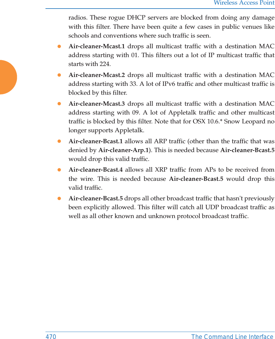
![Wireless Access PointThe Command Line Interface 475management The management command [MyAP(config)# management] enters management mode, where you may configure management parameters.The following types of settings may be configured in management mode:Command Description<cr> Enter management mode.FORMAT:management <cr>Setting Descriptionactivation Start or stop activation server polling.banner Configure login banner messages.clear Remove/clear requested elements.cloud Enable/disable Cloud access.console Configure console management parameters.fips Enable/disable FIPS 140-2, Level 2 Security. See “Implementing FIPS Security” on page 591. help Description of the interactive help system.history Display history of commands executed.https Enable/disable HTTPS access.license Set access point software license keyload Load running configuration from flash.max-auth-attemptsMaximum number of authentication (login) attempts (0 means unlimited).more Turn on or off terminal pagination.](https://usermanual.wiki/Cambium-Networks/XR620.User-Manual/User-Guide-3002682-Page-501.png)
![Wireless Access PointThe Command Line Interface 477mdmThe mdm command [MyAP(config)# mdm] is used to configure Mobile Device Management Server settings. See also, “Mobile” on page 406. xircon Enable/disable Xircon access. See Xircon User’s Guide for more information.Command Descriptionairwatch api Set Location Server customer key.FORMAT:mdm airwatch api The following types of settings may be configured in management mode:zaccess-error Set AirWatch API access error action zkey Set AirWatch API keyzpassword Set AirWatch API passwordzpoll-period Set AirWatch API poll periodztimeout Set AirWatch API timeoutzurl Set AirWatch API URLzusername Set AirWatch API usernameredirect-url Set URL to redirect clients to.FORMAT:mdm airwatch redirect-url <URL-string> Setting Description](https://usermanual.wiki/Cambium-Networks/XR620.User-Manual/User-Guide-3002682-Page-503.png)
![Wireless Access Point478 The Command Line Interfacemore The more command [MyAP(config)# more] is used to turn terminal pagination ON or OFF.Command DescriptiondisableoffTurn OFF terminal pagination.FORMAT:more offenableonTurn ON terminal pagination.FORMAT:more on](https://usermanual.wiki/Cambium-Networks/XR620.User-Manual/User-Guide-3002682-Page-504.png)
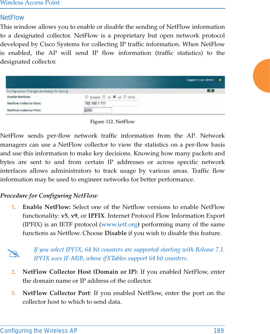
![Wireless Access PointThe Command Line Interface 479netflowThe netflow command [MyAP(config-netflow)#] is used to enable or disable, or configure sending IP flow information (traffic statistics) to the collector you specify.Command Descriptioncollector Set the Netflow collector IP address or fully qualified domain name (host.domain). Only one collector may be set. If port is not specified, the default is 2055. FORMAT:netflow collector host {<ip-addr> | <domain>} [port <port#>]disableoffDisable netflow.FORMAT:netflow disableipfix Enable NetFlow IPFIX probe.off Disable netflow.FORMAT:netflow offv5 Enable NetFlow v5 probe.v9 Enable Netflow v9 probe.](https://usermanual.wiki/Cambium-Networks/XR620.User-Manual/User-Guide-3002682-Page-505.png)
![Wireless Access Point480 The Command Line Interfaceno The no command [MyAP(config)# no] is used to disable a selected element or set the element to its default value.Command Description2.4GHz Disable all 2.4GHz IAPs.5GHz Disable all 5GHz IAPs.acl Disable the Access Control List.FORMAT:no aclclear-text Disable entry and display of passwords and secrets in the clear.gig1 Disable gig1.gig2 Disable gig2.https Disable https access.FORMAT:no httpsintrude-detect Disable intrusion detection.FORMAT:no intrude-detectmanagement Disable management on all Ethernet interfaces.FORMAT:no managementmore Disable terminal pagination.FORMAT:no morentp Disable the NTP server.FORMAT:no ntp](https://usermanual.wiki/Cambium-Networks/XR620.User-Manual/User-Guide-3002682-Page-506.png)
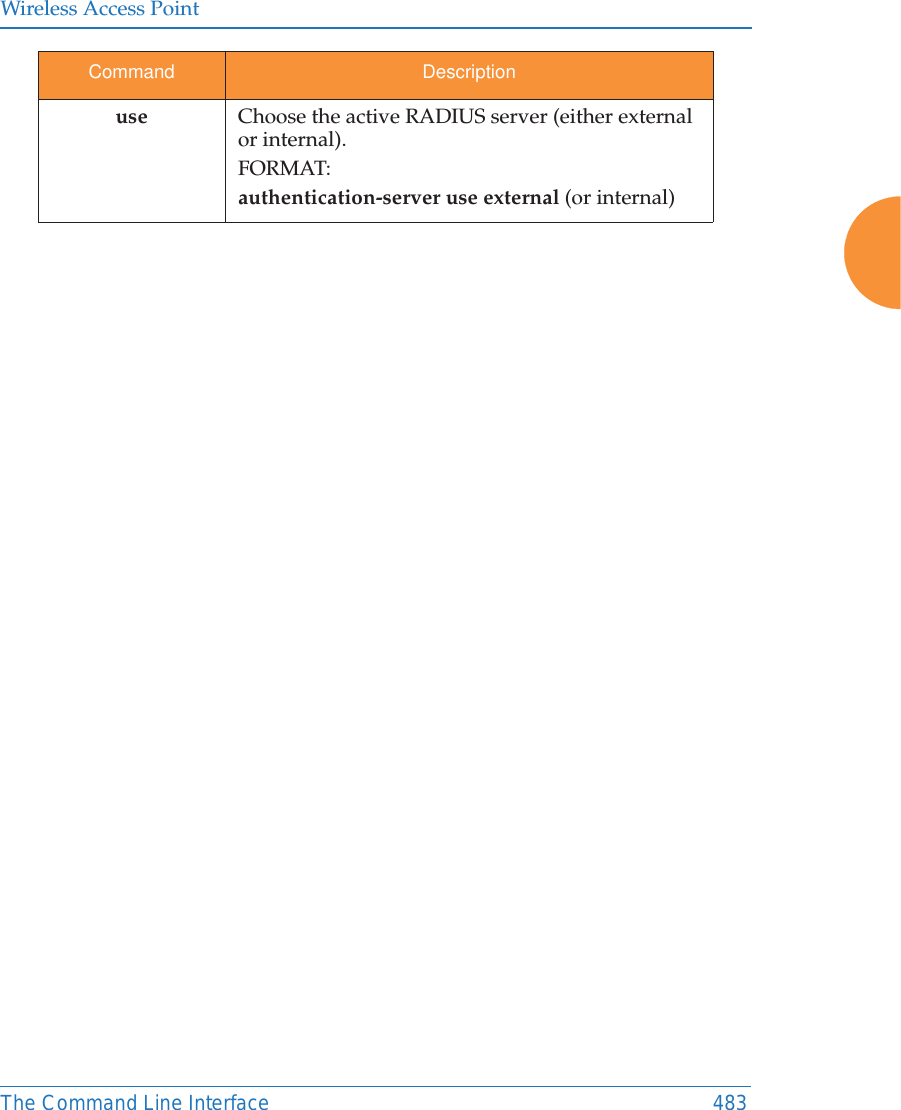
![Wireless Access Point482 The Command Line Interfacequit The quit command [MyAP(config)# quit] is used to exit the Command Line Interface.authentication-server The authentication-server command [MyAP(config-authserver)#] is used to configure the external and internal RADIUS server parameters.Command Description<cr> Exit the Command Line Interface.FORMAT:quitIf you have made any configuration changes and your changes have not been saved, you are prompted to save your changes to Flash.At the prompt, answer Yes to save your changes, or answer No to discard your changes.Command Descriptionactive-directory Configure Active Directory parameters.external-radius Configure an external RADIUS server.FORMAT:authentication-server external-radiusTo configure a RADIUS server (primary, secondary, or accounting server, by IP address or host name), and the reporting interval use:authentication-server external-radius accountinginternal-radius Configure the internal RADIUS server.FORMAT: authentication-server internal-radius](https://usermanual.wiki/Cambium-Networks/XR620.User-Manual/User-Guide-3002682-Page-508.png)
![Wireless Access Point484 The Command Line Interfacereboot The reboot command [MyAP(config)# reboot] is used to reboot the AP. If you have unsaved changes, the command will notify you and give you a chance to cancel the reboot. reset The reset command [MyAP(config)# reset] is used to reset all settings to their default values then reboot the AP.Command Description<cr> Reboot the AP.FORMAT:rebootdelay Reboot the AP after a delay of 1 to 60 seconds.FORMAT:reboot delay [n]Command Description<cr> Reset all configuration parameters to their factory default values.FORMAT:resetThe AP is rebooted automatically.preserve-ip-settingsPreserve all ethernet and VLAN settings and reset all other configuration parameters to their factory default values.FORMAT:reset preserve-ip-settingsThe AP is rebooted automatically.](https://usermanual.wiki/Cambium-Networks/XR620.User-Manual/User-Guide-3002682-Page-510.png)
![Wireless Access PointThe Command Line Interface 485restore The restore command [MyAP(config)# restore] is used to restore configuration to a version that was previously saved locally. Command Description?Use this to display the list of available config files.FORMAT:restore ?<filename> Enter the name of the locally saved configuration to restore.FORMAT:restore <config-filename>](https://usermanual.wiki/Cambium-Networks/XR620.User-Manual/User-Guide-3002682-Page-511.png)
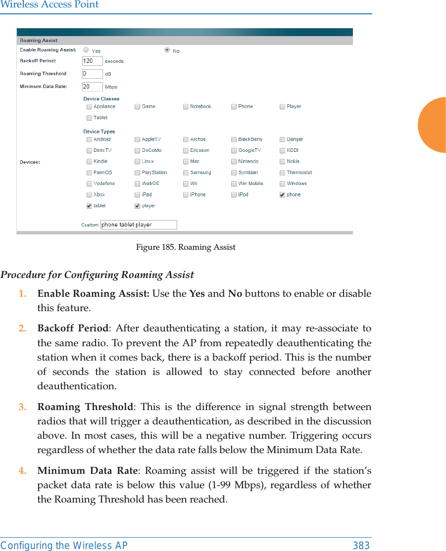
![Wireless Access Point486 The Command Line Interfaceroaming-assistThe roaming-assist command [MyAP(config)# roaming-assist] is used to configure roaming assistance settings. See also, “Roaming Assist” on page 382. Command Descriptiondata-rate Set minimum packet data rate before roaming, in Mbps.FORMAT:roaming-assist data-rate <1-99> devices Set device types or classes to assist.FORMAT:roaming-assist devices all | unidentified | DEVICE-CLASS <ID-string> | DEVICE-TYPE <ID-string>disableoffDisable roaming assist.FORMAT:roaming-assist disableenableonEnable roaming assist.FORMAT:roaming-assist enableperiod Set roaming assist backoff period (seconds).FORMAT:roaming-assist period <#-seconds> threshold Set roaming RSSI threshold in db relative to RSSI of nearest AP.FORMAT:roaming-assist threshold <-50 to 50>](https://usermanual.wiki/Cambium-Networks/XR620.User-Manual/User-Guide-3002682-Page-512.png)
![Wireless Access PointThe Command Line Interface 487run-tests The run-tests command [MyAP(run-tests)#] is used to enter run-tests mode, which allows you to perform a range of tests on the AP.Command Description@Execute command from historyad-authenticate Test domain user authentication.ad-check-secret Check machine trust secret.ad-debug-info Display detailed Active Directory information.ad-list-groups List all domain groups.ad-status Display Active Directory status.capture Execute a packet capture.clear Remove/clear requested elements.diagnostic-log Generate diagnostic log file.end Exit configuration mode.help Description of the interactive help system.history Display history of commands executed.iperf Execute iperf utility.FORMAT:run-tests iperfled LED test.FORMAT:run-tests led [flash | rotate] memtest Execute memory tests.FORMAT:run-tests memtestmore Turn on or off terminal pagination.](https://usermanual.wiki/Cambium-Networks/XR620.User-Manual/User-Guide-3002682-Page-513.png)
![Wireless Access Point488 The Command Line Interfaceping Execute ping utility.FORMAT:run-tests ping [host-name | ip-addr] quick-config Apply quick configuration template.quit Exit the command line interface.radius-ping Special ping utility to test the connection to a RADIUS server.FORMAT:run-tests radius-ping [external | ssid <ssidnum>] [primary | secondary] user <raduser> password <radpasswd> auth-type [CHAP | PAP]run-tests radius-ping [internal | server <radserver> port <radport> secret <radsecret> ] user <raduser> password <radpasswd> auth-type [CHAP | PAP]You may select a RADIUS server that you have already configured (ssid or external or internal) or specify another server. restore Restore to previous saved configuration.revert Revert to saved configuration after delay if configuration is not saved.save Save running configuration to flash.search Search show command output for pattern.show Display current information about the selected item.site-survey Enable or disable site survey mode.FORMAT:run-tests site-survey [on | off | enable | disable] Command Description](https://usermanual.wiki/Cambium-Networks/XR620.User-Manual/User-Guide-3002682-Page-514.png)
![Wireless Access PointThe Command Line Interface 489security The security command [MyAP(config-security)#] is used to establish the security parameters for the AP.ssh Execute ssh utility.FORMAT:run-tests ssh [hostname | ip-addr] [command-line-switches (optional)] tcpdump Execute tcpdump utility to dump traffic for selected interface or VLAN. Supports 802.11 headers.FORMAT:run-tests tcpdumptelnet Execute telnet utility.FORMAT:run-tests telnet [hostname | ip-addr] [command-line-switches (optional)] traceroute Execute traceroute utility.FORMAT:run-tests traceroute [host-name | ip-addr]uptime Display time since last boot.Command Descriptionwep Set the WEP encryption parameters.FORMAT:security wepwpa Set the WEP encryption parameters.FORMAT:security wpaCommand Description](https://usermanual.wiki/Cambium-Networks/XR620.User-Manual/User-Guide-3002682-Page-515.png)
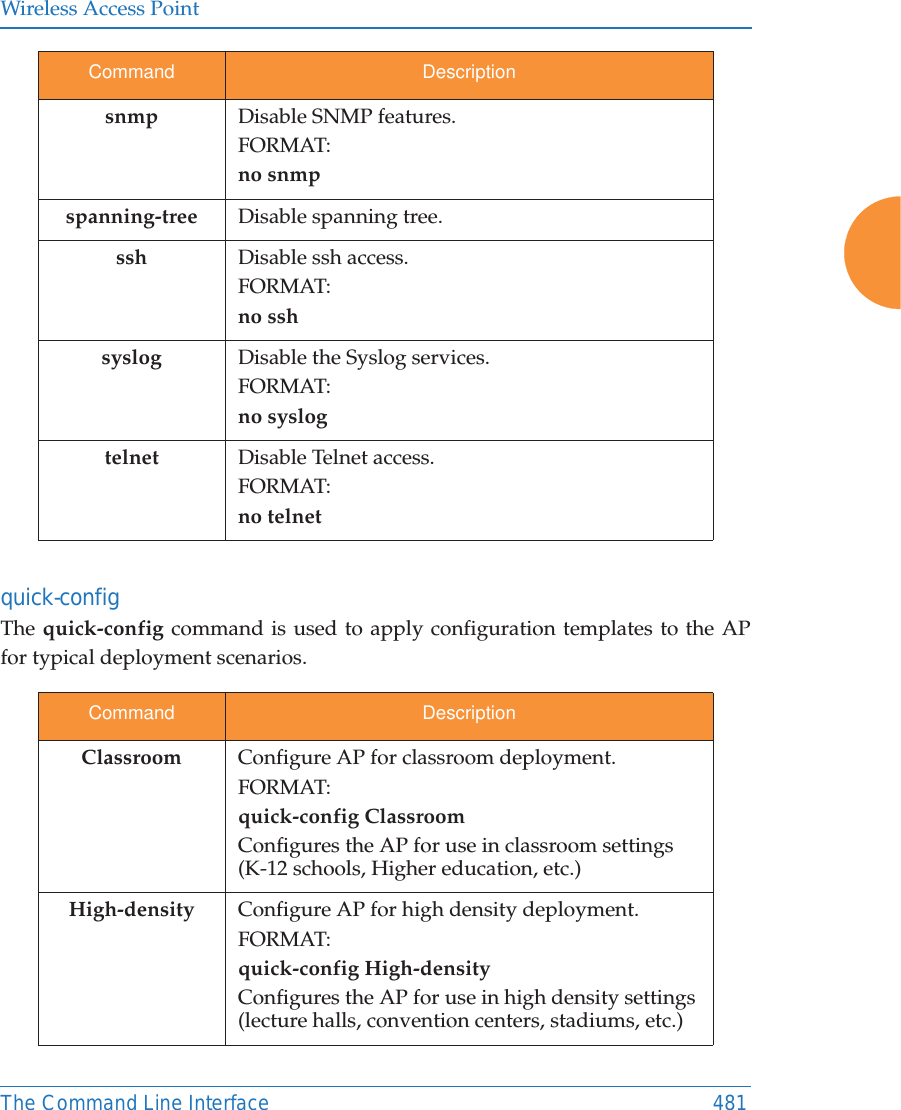
![Wireless Access Point490 The Command Line Interfacesnmp The snmp command [MyAP(config-snmp)#] is used to enable, disable, or configure SNMP.Command Descriptiontrap Configure traps for SNMP. Up to four trap destinations may be configured, and you may specify whether to send traps for authentication failure. FORMAT:snmp trap v2 Enable SNMP v2.FORMAT:snmp v2v3 Enable SNMP v3.FORMAT:snmp v3](https://usermanual.wiki/Cambium-Networks/XR620.User-Manual/User-Guide-3002682-Page-516.png)
![Wireless Access PointThe Command Line Interface 491ssid The ssid command [MyAP(config-ssid)#] is used to establish your SSID parameters.Command Descriptionadd Add an SSID.FORMAT:ssid add [newssid]del Delete an SSID.FORMAT:ssid del [oldssid]edit Edit an existing SSID.FORMAT:ssid edit [existingssid]reset Delete all SSIDs and restore the default SSID.FORMAT:ssid resetstations Set station limit for this SSID.traffic Set traffic limits for this SSID](https://usermanual.wiki/Cambium-Networks/XR620.User-Manual/User-Guide-3002682-Page-517.png)
![Wireless Access Point492 The Command Line Interfacesyslog The syslog command [MyAP(config-syslog)#] is used to enable, disable, or configure the Syslog server.Command Descriptionconsole Enable or disable the display of Syslog messages on the console, and set the level to be displayed. All messages at this level and lower (i.e., more severe) will be displayed.FORMAT:syslog console [on/off] level [0-7]disableoffDisable the Syslog server.FORMAT:syslog disableemail Disable the Syslog server.FORMAT:syslog email from [email-from-address] level [0-7] password [email-acct-password] server [email-server-IPaddr] test [test-msg-text] to-list [recipient-email-addresses] user [email-acct-username]enableonEnable the Syslog server.FORMAT:syslog enablelocal-file Set the size and/or severity level (all messages at this level and lower will be logged).FORMAT:syslog local-file size [1-500] level [0-7]no Disable the selected feature.FORMAT:syslog no [feature]](https://usermanual.wiki/Cambium-Networks/XR620.User-Manual/User-Guide-3002682-Page-518.png)
![Wireless Access PointThe Command Line Interface 493tunnel The tunnel command [MyAP(config-tunnel)#] is used to establish your tunnel parameters.primary Set the IP address of the primary Syslog server and/or the severity level of messages to be logged.FORMAT:syslog primary [1.2.3.4] level [0-7]secondary Set the IP address of the secondary (backup) Syslog server and/or the severity level of messages to be logged.FORMAT:syslog primary [1.2.3.4] level [0-7]sta-format Select format of station information in Syslog messages.sta-url-log Enable or disable station URL logging.tertiary Set Tertiary Syslog Server parameters.time-format Select format of date/time information in Syslog messages.Command Descriptionadd Add a tunnel.FORMAT:tunnel add [newtunnel]delete Delete a tunnel.FORMAT:tunnel delete [oldtunnel]Command Description](https://usermanual.wiki/Cambium-Networks/XR620.User-Manual/User-Guide-3002682-Page-519.png)
![Wireless Access Point494 The Command Line Interfaceuptime The uptime command [MyAP(config)# uptime] is used to display the elapsed time since you last rebooted the AP. vlan The vlan command [MyAP(config-vlan)#] is used to establish your VLAN parameters.edit Modify an existing tunnel.FORMAT:tunnel edit [existingtunnel]reset Delete all existing tunnels.FORMAT:tunnel resetCommand Descriptioncontinuous Continuously update information.<cr> Display time since last reboot.FORMAT:uptimeCommand Descriptionadd Add a VLAN.FORMAT:vlan add [newvlan]Command Description](https://usermanual.wiki/Cambium-Networks/XR620.User-Manual/User-Guide-3002682-Page-520.png)
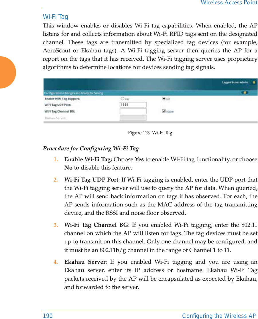
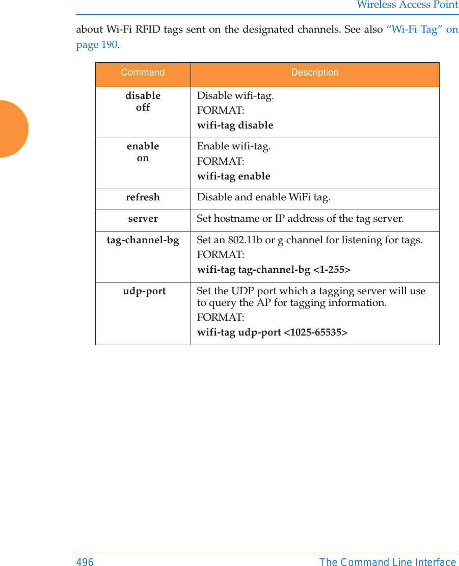
![Wireless Access PointThe Command Line Interface 495wifi-tag The wifi-tag command [MyAP(config-wifi-tag)#] is used to enable or disable Wi-Fi tag capabilities. When enabled, the AP listens for and collects information default-route Assign a VLAN for the default route (for outbound management traffic).FORMAT:vlan default-route [defaultroute]delete Delete a VLAN.FORMAT:vlan delete [oldvlan]edit Modify an existing VLAN.FORMAT:vlan edit [existingvlan]native-vlan Assign a native VLAN (traffic is untagged).FORMAT:vlan native-vlan [nativevlan]no Disable the selected feature.FORMAT:vlan no [feature]reset Delete all existing VLANs.FORMAT:vlan resetCommand Description](https://usermanual.wiki/Cambium-Networks/XR620.User-Manual/User-Guide-3002682-Page-521.png)

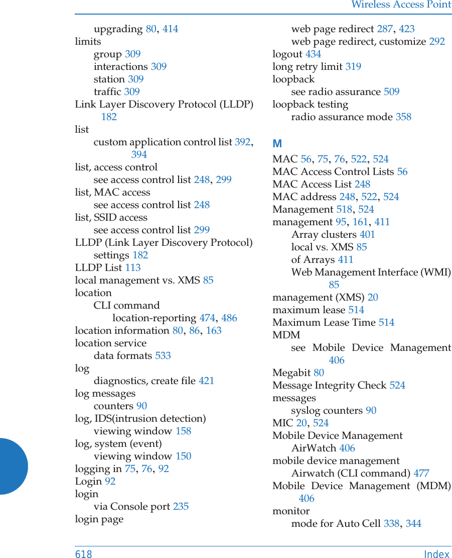
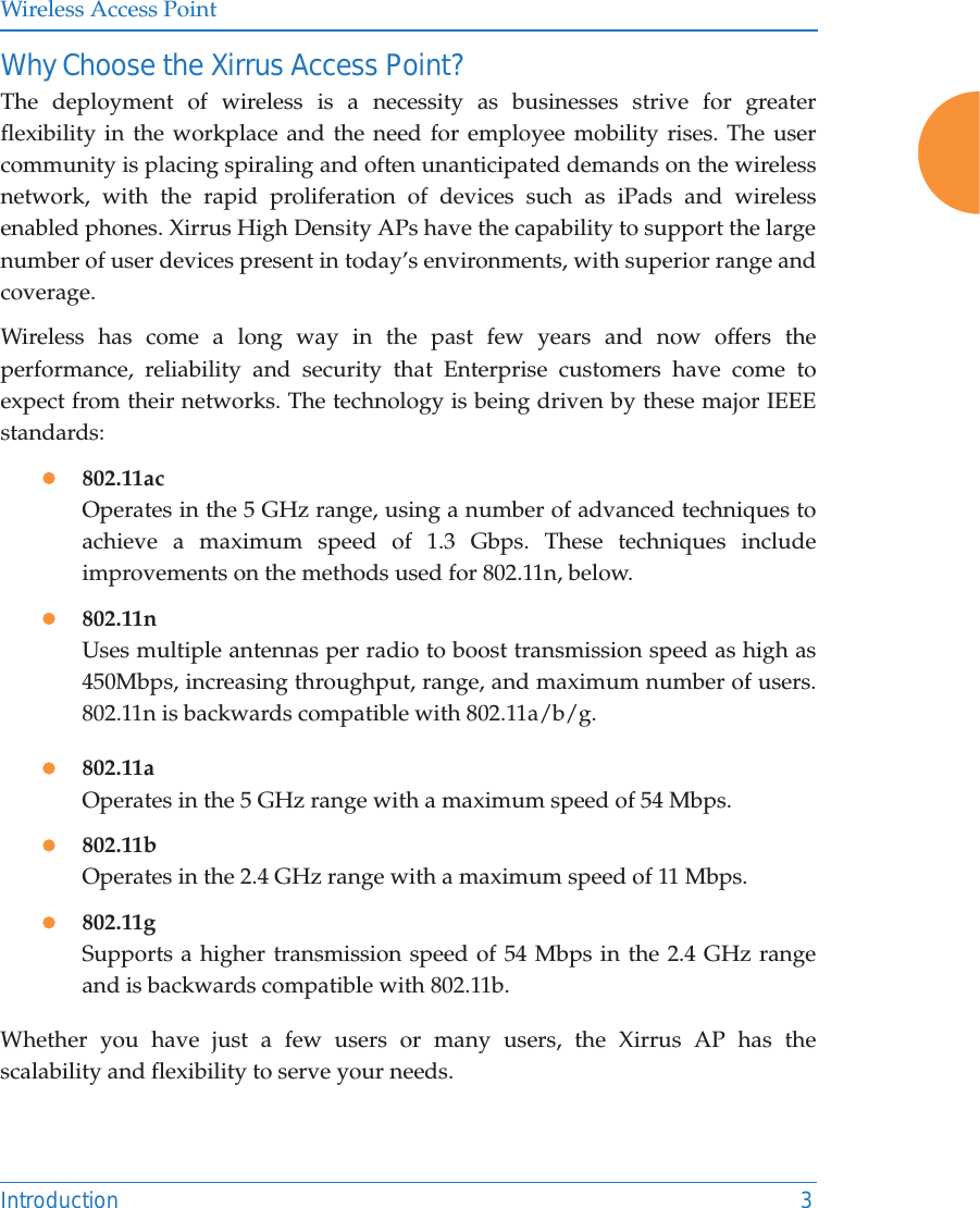
![Wireless Access Point539Sample Output for the Upgrade Procedure: The user actions are highlighted in the output below, for clarity. Output will be in the form shown below, but may not be exactly the same.Username: adminPassword: *****XR50326004F89# configureXR50326004F89(config)# rebootAre you sure you want to reboot? [yes/no]: yesArray is being rebooted...Sending trap .... doneRebooting ...Xirrus Boot Loader 6.3.0-6171 (Dec 11 2014 - 15:41:48)Board | Xirrus CN5020-CP CPU BoardClocks | CPU : 300 MHz DDR : 666 MHzI2C Bus | 384 KHz, sampling at 11 MHzReset | Reset requestedWatchdog | Enabled (5 secs)System DDR | 512 MB, DDR2 Unbuffered non-ECCFLASH | 2 MB, CRC: OKRTC | Fri 2014-Dec-12 19:40:11 GMTCPU BIST | passPCI | PCI 32-bit, BAR 0: 0x08000000Radios | 0 1Network | eth0USB | 1 Storage Device foundEnvironment | InitializedIn: ser_xcOut: ser_xcErr: ser_xcPress space bar to exit to bootloader: 0](https://usermanual.wiki/Cambium-Networks/XR620.User-Manual/User-Guide-3002682-Page-565.png)
![Wireless Access Point540Username: adminPassword: *****XBL>dhcp[DHCP ] Device : eth0 - 1000 Mbps Full Duplex[DHCP ] IP Addr : 10.100.44.48XBL>dir[USB 0 ] Directory of / Date Time Size File or Directory name----------- -------- ---------- ---------------------------2014-Dec-12 18:47:16 17776 factory.conf2014-Dec-12 19:39:42 17810 lastboot.conf2014-Dec-12 19:37:56 17810 saved.conf2014-Dec-11 23:57:16 ssl/2014-Dec-11 23:57:16 wmi/2014-Dec-12 19:35:18 history/2014-Dec-12 18:49:12 storage/2014-Dec-12 18:46:28 wpr/2014-Dec-12 19:39:20 tmp/2014-Dec-12 18:41:28 77993740 XS-7.1.2-5152.bin2014-Dec-12 19:38:14 29 lastboot.old2014-Dec-12 19:38:58 29 lastboot2014-Dec-12 18:47:26 proxy-client/6 file(s), 7 dir(s)XBL>update server 10.100.44.44 XS-7.2.3-5452.bin[TFTP ] Device : eth0 - 1000 Mbps Full Duplex[TFTP ] Client : 10.100.44.48[TFTP ] Server : 10.100.44.44[TFTP ] File : XS-7.2.3-5452.bin[TFTP ] Address : 0x6000000[TFTP ] Loading : ##################################################](https://usermanual.wiki/Cambium-Networks/XR620.User-Manual/User-Guide-3002682-Page-566.png)
![Wireless Access Point541[TFTP ] Loading : ################################################ done[TFTP ] Complete: 7.4 sec, 10.1 MB/sec[TFTP ] Bytes : 78027656 (4a69b88 hex), 10226 Kbytes/sec[USB 0 ] File : XS-7.2.3-5452.bin[USB 0 ] Address : 0x6000000[USB 0 ] Saving : ##################################################[USB 0 ] Saving : ##################################################[USB 0 ] Saving : ##################################################[USB 0 ] Saving : ##################################################[USB 0 ] Saving : ##################################################[USB 0 ] Saving : ############################################## done[USB 0 ] Complete: 59.5 sec, 1.3 MB/sec[USB 0 ] Bytes : 78027656 (4a69b88 hex)XBL>dir[USB 0 ] Directory of / Date Time Size File or Directory name----------- -------- ---------- ---------------------------2014-Dec-12 18:47:16 17776 factory.conf2014-Dec-12 19:39:42 17810 lastboot.conf2014-Dec-12 19:37:56 17810 saved.conf2014-Dec-11 23:57:16 ssl/2014-Dec-11 23:57:16 wmi/2014-Dec-12 19:35:18 history/2014-Dec-12 18:49:12 storage/2014-Dec-12 18:46:28 wpr/2014-Dec-12 19:39:20 tmp/2014-Dec-12 18:41:28 77993740 XS-7.1.2-5152.bin2014-Dec-12 19:38:14 29 lastboot.old2014-Dec-12 19:38:58 29 lastboot2014-Dec-12 18:47:26 proxy-client/2014-Dec-12 19:41:22 78027656 XS-7.2.3-5452.bin7 file(s), 7 dir(s)XBL>env set bootfile_active XS-7.2.3-5452.binXBL>env save](https://usermanual.wiki/Cambium-Networks/XR620.User-Manual/User-Guide-3002682-Page-567.png)
![Wireless Access Point542[Flash ] Saving : Environment 4 KBXBL>boot[USB 0 ] File : XS-7.2.3-5452.bin[USB 0 ] Address : 0x6000000[USB 0 ] Loading : ##################################################[USB 0 ] Loading : ################################################ done[USB 0 ] Complete: 6.5 sec, 11.4 MB/sec[USB 0 ] Bytes : 78027656 (4a69b88 hex)[Boot ] Address : 0x06000000[Image ] Name : XR-7.2.3-5452[Image ] Created : 2014-11-13 7:52:39 UTC[Image ] Type : MIPS Linux Multi-File Image (uncompressed)[Image ] Size : 78027552 Bytes = 74.4 MB[Image ] Contents: File 0: 17248885 Bytes = 16.4 MB[Image ] Contents: File 1: 49149529 Bytes = 46.9 MB[Image ] Contents: File 2: 11629116 Bytes = 11.1 MB[Boot ] Image : Verifying image ....... OK[Boot ] Loading : Multi-File Image .... OK[Boot ] Watchdog: Disabling .... OK[Boot ] Execute : Transferring control to OSInitializing hardware ............ OKXirrus Wi-Fi ArrayArrayOS Version 7.2.3-5452Copyright (c) 2005-2014 Xirrus, Inc.http://www.xirrus.comUsername:](https://usermanual.wiki/Cambium-Networks/XR620.User-Manual/User-Guide-3002682-Page-568.png)
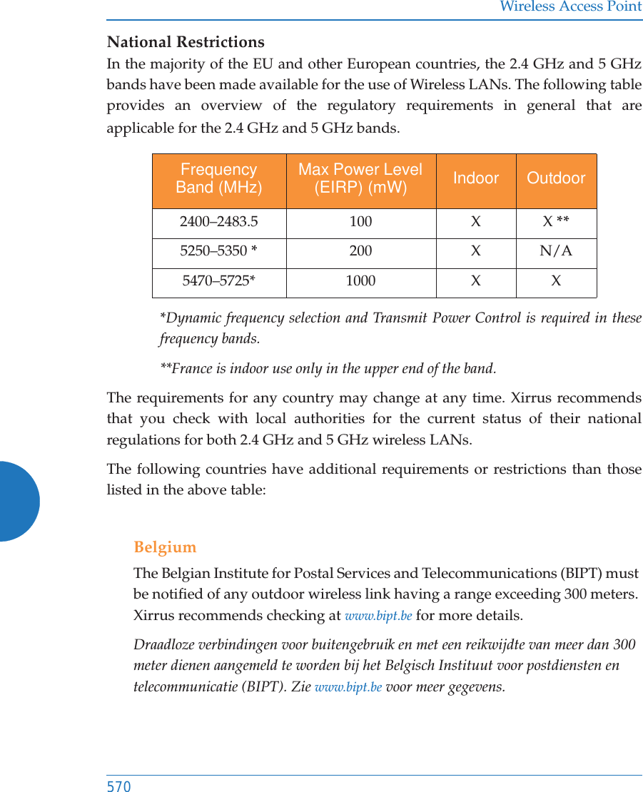
![Wireless Access Point549EU Directive 1999/5/EC Compliance InformationThis section contains compliance information for the Xirrus Wireless AP family of products. The compliance information contained in this section is relevant to the European Union and other countries that have implemented the EU Directive 1999/5/EC.Declaration of Conformity#This Appendix contains Notices, Warnings, and Compliance information forthe XD and XR500/600 Series only. For other models, see the notes at the beginning of this appendix. Cesky [Czech] Toto zahzeni je v souladu se základnimi požadavky a ostatnimi odpovidajcimi ustano veni mi SmČrnice 1999/5/EC.Dansk [Danish] Dette udstyr er i overensstemmelse med de væsentlige krav og andre relevante bestemmelser i Direktiv 1999/5/EF.Deutsch [German] Dieses Gerat entspricht den grundlegenden Anforderungen und den weiteren entsprechenden Vorgaben der Richtinie 1999/5/EU.Eesti [Estonian] See seande vastab direktiivi 1999/5/EU olulistele nöuetele ja teistele as jakohastele sätetele.English This equipment is in compliance with the essential requirements and other relevant provisions of Directive 1999/5/EC.Español [Spain] Este equipo cump le con los requisitos esenciales asi como con otras disposiciones de la Directiva 1999/5/CE.ǼȜȜȘȞȣțȘ [Greek] ǹȣIJȩȗ Ƞ İȟȠʌȜIJıȝȩȗ İȓȞĮȚ ıİ ıȣȝȝȩȡijȦıȘ ȝİ IJȚȗ ȠȣıȚȫįİȚȗ ĮʌĮȚIJȒıİȚȗ țĮȚ ȪȜȜİȗ ıȤİIJȚțȑȗ įȚĮIJȐȟİȚȗ IJȘȗ ȅįȘȖȚĮȗ 1999/5/EC.](https://usermanual.wiki/Cambium-Networks/XR620.User-Manual/User-Guide-3002682-Page-575.png)
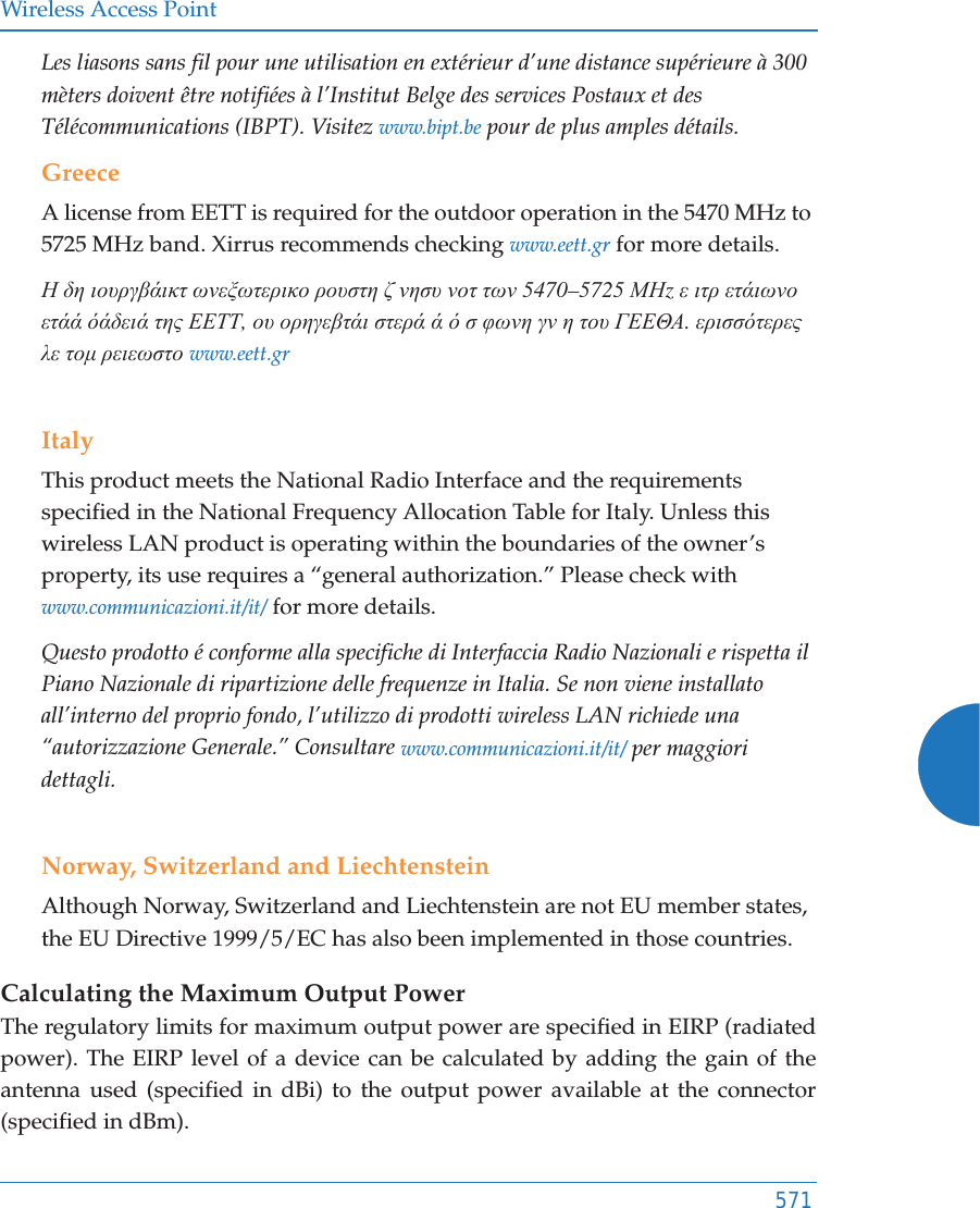
![Wireless Access Point550Français [French] Cet appareil est conforme aux exigences essentielles et aux autres dispositions pertinentes de la Directive 1999/5/EC.Ďslenska [Icelandic] Þetta tæki er samkvæmt grunnkröfum og öðrum viðeigandi ákvæðum Tilskipunar 1999/5/EC.Italiano [Italian] Questo apparato é conforme ai requisiti essenziali ed agli altri principi sanciti dalla Direttiva 1999/5/CE.Latviski [Latvian] ŠƯ iekƗrta atbilst DirektƯvas 1999/5/EK bnjtiskajƗprasƯbƗm un citiem ar to saistƯtajiem noteikumiem.Lietuviǐ [Lithuanian] Šis Ƴrenginys tenkina 1995/5/EB Direktyvos esminius reikalavimus ir kitas šios direktyvos nuostatas.Nederlands [Dutch] Dit apparant voldoet aan de essentiele eisen en andere van toepassing zijnde bepalingen van de Richtlijn 1995/5/EC.Malti [Maltese] Dan l-apparant huwa konformi mal-htigiet essenzjali u l-provedimenti l-ohra rilevanti tad-Direttiva 1999/5/EC.Margyar [Hungarian] Ez a készülék teljesiti az alapvetö követelményeket és más 1999/5/EK irányelvben meghatározott vonatkozó rendelkezéseket.Norsk [Norwegian] Dette utstyret er i samsvar med de grunnleggende krav og andre relevante bestemmelser i EU-direktiv 1999/5/EF.Polski [Polish] Urządzenie jest zgodne z ogólnymi wymaganiami oraz sczególnymi mi warunkami okreĞlony mi Dyrektywą. UE:1999/5/EC.Portuguès [Portuguese] Este equipamento está em conformidade com os requisitos essenciais e outras provisões relevantes da Directiva 1999/5/EC.](https://usermanual.wiki/Cambium-Networks/XR620.User-Manual/User-Guide-3002682-Page-576.png)
![Wireless Access Point551Assessment CriteriaThe following standards were applied during the assessment of the product against the requirements of the Directive 1999/5/EC:zRadio: EN 301 893 and EN 300 328 (if applicable)zEMC: EN 301 489-1 and EN 301 489-17zSafety: EN 60950, EN 62311 and EN 50385CE MarkingFor the Xirrus Wireless AP, the CE mark and Class-2 identifier opposite are affixed to the equipment and its packaging: Russian Certification MarkingFor the Xirrus XR-500, XR-520H, XR-2000, and XR-4000 Series Wireless APs, the approval mark is affixed to the equipment: Slovensko [Slovenian] Ta naprava je skladna z bistvenimi zahtevami in ostalimi relevantnimi popoji Direktive 1999/5/EC.Slovensky [Slovak] Toto zariadenie je v zhode so základnými požadavkami a inými prislušnými nariadeniami direktiv: 1999/5/EC.Suomi [Finnish] Tämä laite täyttää direktiivin 1999/5//EY olennaiset vaatimukset ja on siinä asetettujen muiden laitetta koskevien määräysten mukainen.Svenska [Swedish] Denna utrustning är i överensstämmelse med de väsentliga kraven och andra relevanta bestämmelser i Direktiv 1999/5/EC.](https://usermanual.wiki/Cambium-Networks/XR620.User-Manual/User-Guide-3002682-Page-577.png)

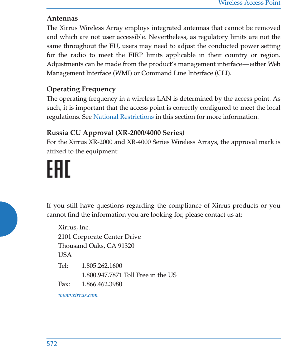
![Wireless Access Point566EU Directive 1999/5/EC Compliance InformationThis section contains compliance information for the Xirrus Wireless Array family of products. The compliance information contained in this section is relevant to the European Union and other countries that have implemented the EU Directive 1999/5/EC.Declaration of Conformity#This Appendix contains Notices, Warnings, and Compliance information for these indoor model series: XR-1000, XR-2000, XR-4000, and XR-6000. This includes the models just listed whether or not they have been upgraded to have IEEE 802.11ac Wave2 wireless capability by replacing existing radios with XI-AC3470 modules.For Notices, Warnings, and Compliance information for other models, see the notes at the beginning of this chapter. Cesky [Czech] Toto zahzeni je v souladu se základnimi požadavky a ostatnimi odpovidajcimi ustano veni mi SmČrnice 1999/5/EC.Dansk [Danish] Dette udstyr er i overensstemmelse med de væsentlige krav og andre relevante bestemmelser i Direktiv 1999/5/EF.Deutsch [German] Dieses Gerat entspricht den grundlegenden Anforderungen und den weiteren entsprechenden Vorgaben der Richtinie 1999/5/EU.Eesti [Estonian] See seande vastab direktiivi 1999/5/EU olulistele nöuetele ja teistele as jakohastele sätetele.English This equipment is in compliance with the essential requirements and other relevant provisions of Directive 1999/5/EC.Español [Spain] Este equipo cump le con los requisitos esenciales asi como con otras disposiciones de la Directiva 1999/5/CE.](https://usermanual.wiki/Cambium-Networks/XR620.User-Manual/User-Guide-3002682-Page-592.png)
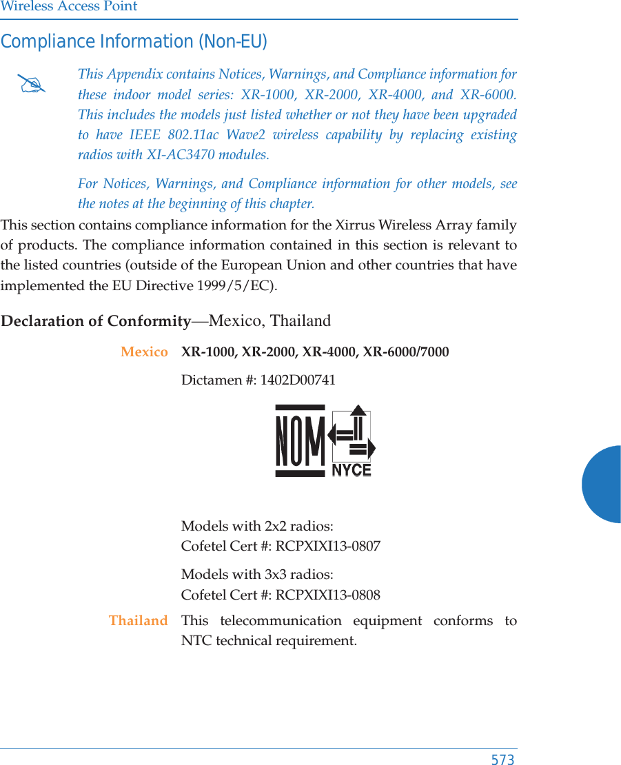
![Wireless Access Point567ǼȜȜȘȞȣțȘ [Greek] ǹȣIJȩȗ Ƞ İȟȠʌȜIJıȝȩȗ İȓȞĮȚ ıİ ıȣȝȝȩȡijȦıȘ ȝİ IJȚȗ ȠȣıȚȫįİȚȗ ĮʌĮȚIJȒıİȚȗ țĮȚ ȪȜȜİȗ ıȤİIJȚțȑȗ įȚĮIJȐȟİȚȗ IJȘȗ ȅįȘȖȚĮȗ 1999/5/EC.Français [French] Cet appareil est conforme aux exigences essentielles et aux autres dispositions pertinentes de la Directive 1999/5/EC.Ďslenska [Icelandic] Þetta tæki er samkvæmt grunnkröfum og öðrum viðeigandi ákvæðum Tilskipunar 1999/5/EC.Italiano [Italian] Questo apparato é conforme ai requisiti essenziali ed agli altri principi sanciti dalla Direttiva 1999/5/CE.Latviski [Latvian] ŠƯ iekƗrta atbilst DirektƯvas 1999/5/EK bnjtiskajƗprasƯbƗm un citiem ar to saistƯtajiem noteikumiem.Lietuviǐ [Lithuanian] Šis Ƴrenginys tenkina 1995/5/EB Direktyvos esminius reikalavimus ir kitas šios direktyvos nuostatas.Nederlands [Dutch] Dit apparant voldoet aan de essentiele eisen en andere van toepassing zijnde bepalingen van de Richtlijn 1995/5/EC.Malti [Maltese] Dan l-apparant huwa konformi mal-htigiet essenzjali u l-provedimenti l-ohra rilevanti tad-Direttiva 1999/5/EC.Margyar [Hungarian] Ez a készülék teljesiti az alapvetö követelményeket és más 1999/5/EK irányelvben meghatározott vonatkozó rendelkezéseket.Norsk [Norwegian] Dette utstyret er i samsvar med de grunnleggende krav og andre relevante bestemmelser i EU-direktiv 1999/5/EF.Polski [Polish] Urządzenie jest zgodne z ogólnymi wymaganiami oraz sczególnymi mi warunkami okreĞlony mi Dyrektywą. UE:1999/5/EC.](https://usermanual.wiki/Cambium-Networks/XR620.User-Manual/User-Guide-3002682-Page-593.png)
![Wireless Access Point568Assessment CriteriaThe following standards were applied during the assessment of the product against the requirements of the Directive 1999/5/EC:zRadio: EN 301 893 and EN 300 328 (if applicable)zEMC: EN 301 489-1 and EN 301 489-17zSafety: EN 50371 to EN 50385, EN 60601, and EN60950CE MarkingFor the Xirrus Wireless Array, the CE mark and Class-2 identifier opposite are affixed to the equipment and its packaging: Portuguès [Portuguese] Este equipamento está em conformidade com os requisitos essenciais e outras provisões relevantes da Directiva 1999/5/EC.Slovensko [Slovenian] Ta naprava je skladna z bistvenimi zahtevami in ostalimi relevantnimi popoji Direktive 1999/5/EC.Slovensky [Slovak] Toto zariadenie je v zhode so základnými požadavkami a inými prislušnými nariadeniami direktiv: 1999/5/EC.Suomi [Finnish] Tämä laite täyttää direktiivin 1999/5//EY olennaiset vaatimukset ja on siinä asetettujen muiden laitetta koskevien määräysten mukainen.Svenska [Swedish] Denna utrustning är i överensstämmelse med de väsentliga kraven och andra relevanta bestämmelser i Direktiv 1999/5/EC.](https://usermanual.wiki/Cambium-Networks/XR620.User-Manual/User-Guide-3002682-Page-594.png)