Cambium Networks XS390016 XS-3900 Wireless LAN Array User Manual xirrus certification
Xirrus, Inc. XS-3900 Wireless LAN Array xirrus certification
Users Manual April 25

XS
3900/3700
WirelessWireless
WirelessWireless
Wireless
LAN ArrayLAN Array
LAN ArrayLAN Array
LAN Array
User’s Guide
April 12th, 2005
DRAFT RELEASE (C)

Copyright © 2005 Xirrus, Inc.
370 North Westlake Blvd, Suite 200
Westlake Village, CA 91362
USA
www.xirrus.com
All rights reserved. This document may not be reproduced or
disclosed in whole or in part by any means without the written
consent of Xirrus, Inc.
Part Number: 800-0006-001
(Rev. A)
Wireless LAN Array
XS-3900, XS-3700, XS-3500

Trademarks
is a trademark of Xirrus, Inc. All other trademarks and brand names
are marks of their respective holders.
Notices
FCC Notice
This device complies with Part 15 of the FCC Rules, with operation subject to the
following two conditions: (1) This device may not cause harmful interference, and
(2) this device must accept any interference received, including interference that
may cause unwanted operation.
This equipment has been tested and found to comply with the limits for a Class A
digital device, pursuant to Part 15 of the FCC rules. These limits are designed to
provide reasonable protection against harmful interference in a residential
installation. This equipment generates, uses and can radiate RF energy and, if not
installed and used in accordance with the instructions, may cause harmful
interference to radio communications. However, there is no guarantee that
interference will not occur in a particular installation. If this equipment does
cause harmful interference to radio or television reception, which can be
determined by turning the equipment off and on, the user is encouraged to try to
correct the interference by one or more of the following safety measures:
zReorient or relocate the receiving antenna.
zIncrease the separation between the equipment and the receiver.
zConsult the dealer or an experienced wireless technician for help.
Use of a shielded twisted pair (STP) cable must be used for all Ethernet
connections in order to comply with EMC requirements.
RF Radiation Hazard Warning
To ensure compliance with FCC RF exposure requirements, this device must be
installed in a location where the antennas of the device will have a minimum
distance of at least 25 cm (9.84 inches) from all persons. Using higher gain
antennas and types of antennas not certified for use with this product is not
allowed. The device shall not be co-located with another transmitter.
Non-Modification Statement
Unauthorized changes or modifications to the device are not permitted. Use only
the supplied internal antenna, or external antennas supplied by the manufacturer.
Modifications to the device will void the warranty and may violate FCC
regulations. Please go to the Xirrus Web site for a list of all approved antennas.
Indoor Use
This product has been designed for indoor use. Operation of channels in the
5250MHz to 5350MHz band is permitted indoors only to reduce the potential for
harmful interference to co-channel mobile satellite systems.
Maximum Antenna Gain
Currently, the maximum antenna gain is limited to 6dBi for operation in the
5250MHz to 5350MHz band and 5725MHz to 5825MHz band and must not
exceed maximum EIRP limits set by the FCC / Industry Canada.
High Power Radars
High power radars are allocated as primary users (meaning they have priority) in
the 5250MHz to 5350MHz and 5650MHz to 5850MHz bands. These radars could
cause interference and/or damage to LELAN devices used in Canada.
Industry Canada Notice and Marking
This Class A digital apparatus complies with Canadian ICES-003.
Cet appareil numérique de la classe A est conforme à la norme NMB-003 du Canada.
The term “IC:” before the radio certification number only signifies that Industry
Canada technical specifications were met.
Safety Warnings
Translated safety warnings appear on the following page.
!Safety Warnings
Read all user documentation before powering this device. All Xirrus
interconnected equipment should be contained indoors. This product is
not suitable for outdoor operation. Please verify the integrity of the
system ground prior to installing Xirrus equipment. Additionally,
verify that the ambient operating temperature does not exceed 50°C.
!Explosive Device Proximity Warning
Do not operate the XS-3900 unit near unshielded blasting caps or in an
explosive environment unless the device has been modified to be
especially qualified for such use.
!Lightning Activity Warning
Do not work on the XS-3900 or connect or disconnect cables during
periods of lightning activity.
!Circuit Breaker Warning
The XS-3900 relies on the building’s installation for over current
protection. Ensure that a fuse or circuit breaker no larger than 120 VAC,
15A (U.S.) or 240 VAC, 10A (International) is used on all current-
carrying conductors.
Translated Safety Warnings
Avertissements de Sécurité
!Sécurité
Lisez l'ensemble de la documentation utilisateur avant de mettre cet
appareil sous tension. Tous les équipements Xirrus interconnectés
doivent être installés en intérieur. Ce produit n'est pas conçu pour être
utilisé en extérieur. Veuillez vérifier l'intégrité de la terre du système
avant d'installer des équipements Xirrus. Vérifiez également que la
température de fonctionnement ambiante n'excède pas 50°C.
!Proximité d'appareils explosifs
N'utilisez pas l'unité XS-3900 à proximité d'amorces non blindées ou
dans un environnement explosif, à moins que l'appareil n'ait été
spécifiquement modifié pour un tel usage.
!Foudre
N'utilisez pas l'unité XS-3900 et ne branchez pas ou ne débranchez pas
de câbles en cas de foudre.
!Disjoncteur
L'unité XS-3900 dépend de l'installation du bâtiment pour ce qui est de
la protection contre les surintensités. Assurez-vous qu'un fusible ou
qu'un disjoncteur de 120 Vca, 15 A (États-Unis) ou de 240 Vca, 10 A
(International) maximum est utilisé sur tous les conducteurs de
courant.
Software License Agreement
PLEASE READ THIS SOFTWARE LICENSE AGREEMENT CAREFULLY
BEFORE DOWNLOADING OR USING THE SOFTWARE.
BY USING ANY LICENSED MATERIALS OR THE EQUIPMENT THAT
CONTAINS THIS PRODUCT, YOU ACKNOWLDEGE THAT YOU HAVE
READ AND UNDERSTOOD ALL THE TERMS AND CONDITIONS OF THIS
AGREEMENT AND THAT YOU ARE CONSENTING TO BE BOUND BY THIS
AGREEMENT. IF YOU DO NOT AGREE TO ALL OF THE TERMS OF THIS
AGREEMENT, RETURN THE UNUSED PRODUCT TO THE PLACE OF
PURCHASE FOR A FULL REFUND.
Single User License Grant: Xirrus, Inc. ("Xirrus") and its suppliers grant to
Customer ("Customer") a nonexclusive and nontransferable license to use the
Xirrus software and related documentation ("Software") in object code form solely
on a single central processing unit owned or leased by Customer or otherwise
embedded in equipment provided by Xirrus.
Multiple-Users License Grant: Xirrus Inc. ("Xirrus") and its suppliers grant to
Customer ("Customer") a nonexclusive and nontransferable license to use the
Xirrus software and related documentation ("Software") in object code form: (i)
installed in a single location on a hard disk or other storage device on up to the
number of computers owned or leased by Customer for which Customer has paid
a license fee ("Permitted Number of Computers"); or (ii) provided the Software is
configured for network use, installed on a single file server for use on a single
local area network for either (but not both) of the following purposes: (a)
permanent installation onto a hard disk or other storage device on up to the
Permitted Number of Computers; or (b) use of the Software over such network,
provided the number of computers connected to the server does not exceed the
Permitted Number of Computers. Customer agrees to (i) only use the programs
contained in the Software for which Customer has paid a license fee (or in the case
of an evaluation copy, those programs Customer is authorized to evaluate), (ii)
not use any component of the Software or Equipment other than solely in
conjunction with operation of the Software and as applicable, Equipment, (iii)
unbundle any component of the Software or Equipment, (iv) use any component
of the Software for the development of or in conjunction with any software
application intended for resale that employs any such component, (v) use the
Licensed Materials or Equipment in life support systems, human implantation,
nuclear facilities or systems or any other application where failure could lead to a
loss of life or catastrophic property damage, or (vi) cause or permit any third
party to do any of the foregoing. Xirrus may provide updates, corrections,
enhancements, modifications or bug fixes for the Software ("Updates") to
Licensee. Any such Update shall be deemed part of the Software and subject to
the license and all other terms and conditions hereunder.
Customer grants to Xirrus or its independent accountants the right to examine its
books, records and accounts during Customer's normal business hours to verify
compliance with the above provisions. In the event such audit discloses that the
Permitted Number of Computers is exceeded, Customer shall promptly pay to
Xirrus the appropriate license fee for the additional computers or users. At Xirrus'
option, Xirrus may terminate this license for failure to pay the required license
fee.
Customer may make one (1) archival copy of the Software provided Customer
affixes to such copy all copyright, confidentiality, and proprietary notices that
appear on the original.
EXCEPT AS EXPRESSLY AUTHORIZED ABOVE, CUSTOMER SHALL NOT:
COPY, IN WHOLE OR IN PART, SOFTWARE OR DOCUMENTATION;
MODIFY THE SOFTWARE; REVERSE COMPILE OR REVERSE ASSEMBLE ALL
OR ANY PORTION OF THE SOFTWARE; OR RENT, LEASE, DISTRIBUTE,
SELL, OR CREATE DERIVATIVE WORKS OF THE SOFTWARE.
Customer agrees that aspects of the licensed materials, including the specific
design and structure of individual programs, constitute trade secrets and/or
copyrighted material of Xirrus. Customer agrees not to disclose, provide, or
otherwise make available such trade secrets or copyrighted material in any form
to any third party without the prior written consent of Xirrus. Customer agrees to
implement reasonable security measures to protect such trade secrets and
copyrighted material. Title to Software and documentation shall remain solely
with Xirrus.
OWNERSHIP. Xirrus or its suppliers own and shall retain all right, title and
interest (including without limitation all intellectual property rights) in and to the
Software and any Update, whether or not made by Xirrus. Licensee
acknowledges that the licenses granted under this Agreement do not provide
Licensee with title to or ownership of the Software, but only a right of limited use
under the terms and conditions of this Agreement. All information or feedback
provided by Licensee to Xirrus with respect to the Software or Equipment shall be
Xirrus' property and deemed confidential information of Xirrus.
LIMITED WARRANTY. Xirrus warrants that for a period of ninety (90) days from
purchase (i) the media on which the Software is furnished will be free of defects in
materials and workmanship under normal use, and (ii) the Software substantially
conforms to its published specifications. Except for the foregoing, the Software is
provided AS IS. This limited warranty extends only to Customer as the original
licensee. Customer's exclusive remedy and the entire liability of Xirrus and its
suppliers under this limited warranty will be, at Xirrus' or its service center's
option, repair, replacement, or refund (if a standalone product) of the Software. In
no event does Xirrus warrant that the Software is error free or that Customer will
be able to operate the Software without problems or interruptions.
This warranty does not apply if the software (a) has been altered, except by
Xirrus, (b) has not been installed, operated, repaired, or maintained in accordance
with instructions supplied by Xirrus, (c) has been subjected to abnormal physical
or electrical stress, misuse, negligence, or accident, or (d) is used in ultra-
hazardous activities.
DISCLAIMER. EXCEPT AS SPECIFIED IN THIS WARRANTY, ALL EXPRESS
OR IMPLIED CONDITIONS, REPRESENTATIONS, AND WARRANTIES
INCLUDING, WITHOUT LIMITATION, ANY IMPLIED WARRANTY OF
MERCHANTABILITY, FITNESS FOR A PARTICULAR PURPOSE,
NONINFRINGEMENT OR ARISING FROM A COURSE OF DEALING, USAGE,
OR TRADE PRACTICE, ARE HEREBY EXCLUDED TO THE EXTENT
ALLOWED BY APPLICABLE LAW.
IN NO EVENT WILL XIRRUS OR ITS SUPPLIERS BE LIABLE FOR ANY LOST
REVENUE, PROFIT, OR DATA, OR FOR SPECIAL, INDIRECT,
CONSEQUENTIAL, INCIDENTAL, OR PUNITIVE DAMAGES HOWEVER
CAUSED AND REGARDLESS OF THE THEORY OF LIABILITY ARISING OUT
OF THE USE OF OR INABILITY TO USE THE SOFTWARE EVEN IF XIRRUS OR
ITS SUPPLIERS HAVE BEEN ADVISED OF THE POSSIBILITY OF SUCH
DAMAGES. In no event shall Xirrus' or its suppliers' liability to Customer,
whether in contract, tort (including negligence), or otherwise, exceed the price
paid by Customer. The foregoing limitations shall apply even if the above-stated
warranty fails of its essential purpose. SOME STATES DO NOT ALLOW
LIMITATION OR EXCLUSION OF LIABILITY FOR CONSEQUENTIAL OR
INCIDENTAL DAMAGES.
The above warranty DOES NOT apply to any beta software, any software made
available for testing or demonstration purposes, any temporary software modules
or any software for which Xirrus does not receive a license fee. All such software
products are provided AS IS without any warranty whatsoever.
This License is effective until terminated. Customer may terminate this License at
any time by destroying all copies of Software including any documentation. This
License will terminate immediately without notice from Xirrus if Customer fails
to comply with any provision of this License. Upon termination, Customer must
destroy all copies of Software.
Software, including technical data, is subject to U.S. export control laws,
including the U.S. Export Administration Act and its associated regulations, and
may be subject to export or import regulations in other countries. Customer
agrees to comply strictly with all such regulations and acknowledges that it has
the responsibility to obtain licenses to export, re-export, or import Software.
This License shall be governed by and construed in accordance with the laws of
the State of California, United States of America, as if performed wholly within
the state and without giving effect to the principles of conflict of law. Customer
may not assign or transfer any of its rights or delegate any of its obligations under
this agreement. No delay, failure or waiver by either party to exercise any right or
remedy under this agreement shall operate to waive any exercise of such right or
remedy or any other right or remedy. If any portion hereof is found to be void or
unenforceable, the remaining provisions of this License shall remain in full force
and effect. This License constitutes the entire License between the parties with
respect to the use of the Software.
Restricted Rights - Xirrus' software is provided to non-Department of Defense
agencies with RESTRICTED RIGHTS and its supporting documentation is
provided with LIMITED RIGHTS. Use, duplication, or disclosure by the
Government is subject to the restrictions as set forth in subparagraph "C" of the
Commercial Computer Software - Restricted Rights clause at FAR 52.227-19. In
the event the sale is to a Department of Defense agency, the government's rights
in software, supporting documentation, and technical data are governed by the
restrictions in the Technical Data Commercial Items clause at DFARS 252.227-
7015 and DFARS 227.7202. Manufacturer is Xirrus, Inc. 370 North Westlake Blvd,
Suite 200 Westlake Village, CA 91362.
PROPRIETARY NOTICES. Customer shall maintain and reproduce all
copyright and other proprietary notices on all copies of the Software in the same
form and manner that such notices are included on the Software.

Wireless LAN Array
Table of Contents i
Table of Contents
All topics listed in this Table of Contents are “clickable,” which means you can
instantly jump to any selected topic with a click of your mouse button. Items that
do not appear in the TOC list—they are part of the Front Matter, prior to this
Table of Contents—include the following:
zTrademarks
zNotices
zSafety Warnings
zTranslated Safety Warnings
zSoftware License Agreement
List of Figures..................................................................................... vii
Introduction ......................................................................................... 1
The Xirrus Family of Products ............................................................................... 1
Nomenclature .................................................................................................... 2
About this User’s Guide .......................................................................................... 2
Organization ...................................................................................................... 2
Notes and Cautions .......................................................................................... 4
Screen Images .................................................................................................... 4
Your User’s Guide as a PDF Document ........................................................ 4
Hyperlinks ......................................................................................................... 4
Why Choose the Wireless LAN Array? ................................................................ 5
Product Overview .................................................................................................... 6
Enterprise Class Security ................................................................................. 6
Deployment Flexibility .................................................................................... 7
Remote DC Power System (Optional) .................................................... 8
Enterprise Class Management ........................................................................ 9
Key Features and Benefits ..................................................................................... 10
High Capacity and High Performance ........................................................ 10
Extended Coverage ......................................................................................... 11
Non-Overlapping Channels .......................................................................... 12
Secure Wireless Access .................................................................................. 12
Wi-Fi Standards Compliance ........................................................................ 12

Wireless LAN Array
ii Table of Contents
Applications Enablement .............................................................................. 12
SDMA Optimization ...................................................................................... 12
Easy Deployment ............................................................................................ 12
Product Specifications (XS-3900) ......................................................................... 13
Installing the XS-3900..................................................................... 17
Installation Prerequisites ...................................................................................... 17
Optional Network Components ................................................................... 19
Client Requirements ....................................................................................... 19
Planning Your Installation .................................................................................... 20
General Deployment Considerations .......................................................... 20
Coverage and Capacity Planning ................................................................. 21
Placement .................................................................................................. 21
RF Patterns ................................................................................................ 22
Calculating Areas .................................................................................... 23
Capacity and Cell Sizes ........................................................................... 24
Sample 802.11a Cells ............................................................................... 25
Fine Tuning Cell Sizes ............................................................................. 26
Roaming Considerations ........................................................................ 26
Allocating Channels ................................................................................ 27
Deployment Examples ............................................................................ 28
Failover Planning ............................................................................................ 29
Unit Failover Protection .......................................................................... 29
Port Failover Protection .......................................................................... 30
Switch Failover Protection ..................................................................... 30
Power Planning ............................................................................................... 31
AC Power .................................................................................................. 31
Remote Distributed DC Power .............................................................. 31
Security Planning ............................................................................................ 31
Wireless Encryption ................................................................................ 31
Authentication ......................................................................................... 32
Network Management Planning .................................................................. 33
Deployment Summary ................................................................................... 34
Installation Workflow ........................................................................................... 35
Unpacking the XS-3900 ......................................................................................... 36
Installing the XS-3900 ............................................................................................ 37
Choosing a Location ....................................................................................... 37

Wireless LAN Array
Table of Contents iii
Wiring Considerations ............................................................................ 37
Mounting the Unit .......................................................................................... 38
Attaching the T-Bar Clips ....................................................................... 39
Installing the Mounting Plate ................................................................ 40
Connecting the Cables ............................................................................ 41
Attaching the Array to the Mounting Plate ......................................... 42
Dismounting the Array ........................................................................... 43
Powering Up the XS-3900 ..................................................................................... 44
Establishing Communication with the Array .................................................... 46
Using the Serial Port ....................................................................................... 46
Using the Ethernet Ports ................................................................................ 46
Logging In ........................................................................................................ 46
Performing the Express Setup Procedure ........................................................... 47
The Web Management Interface ................................................... 53
An Overview .......................................................................................................... 53
Content ............................................................................................................. 54
Structure ........................................................................................................... 55
Status Bar .................................................................................................. 56
Applying Configuration Changes ................................................................ 56
Character Restrictions .................................................................................... 56
Configuring the XS-3900................................................................. 57
Logging In ............................................................................................................... 57
Making Configuration Changes to the XS-3900 ................................................ 58
Array Status ..................................................................................................... 58
Express Setup .................................................................................................. 61
Network Interfaces ......................................................................................... 66
Network Settings ..................................................................................... 67
VLAN Settings ......................................................................................... 71
Network Statistics .................................................................................... 74
DHCP Server Settings ............................................................................. 75
DNS Settings ............................................................................................. 76
IAP Interfaces .................................................................................................. 78
IAP Settings .............................................................................................. 79
Global Settings ......................................................................................... 82
Global Settings .11a ................................................................................. 84

Wireless LAN Array
iv Table of Contents
Global Settings .11bg ............................................................................... 86
IAP LED Settings ..................................................................................... 88
Statistics ..................................................................................................... 89
Statistics (for specific radios) .................................................................. 90
SSID Management .......................................................................................... 92
Understanding SSIDs .............................................................................. 92
Create SSID ............................................................................................... 94
Edit SSID ................................................................................................... 95
Security ............................................................................................................. 97
Security Management ............................................................................. 98
Radius Server ......................................................................................... 103
Radius User ............................................................................................ 105
MAC Access List .................................................................................... 106
Create Admin ......................................................................................... 108
Edit Admin ............................................................................................. 109
Users ............................................................................................................... 110
Services ........................................................................................................... 111
System Log ............................................................................................. 112
SNMP ...................................................................................................... 113
Software .......................................................................................................... 114
Tools ................................................................................................................ 115
Event Log ....................................................................................................... 116
The Command Line Interface ...................................................... 117
Establishing a Secure Shell (SSH) Connection ................................................. 117
Basic Commands .................................................................................................. 118
Help ................................................................................................................ 118
Tab Key ........................................................................................................... 118
? Key ............................................................................................................... 118
Save ................................................................................................................. 118
Command Modes ................................................................................................. 118
Configure Mode ............................................................................................ 118
SSID Mode ..................................................................................................... 118
Radius Mode .................................................................................................. 119
Run Test Mode .............................................................................................. 119
Selecting Interfaces .............................................................................................. 119
Command Line Keywords ................................................................................. 120

Wireless LAN Array
Table of Contents v
Interface Selection ......................................................................................... 121
Interface Configuration ................................................................................ 122
Radio Configuration ..................................................................................... 126
Beacon Information ...................................................................................... 136
System Administration ................................................................................ 137
System Testing .............................................................................................. 142
Security ........................................................................................................... 143
Station Timeouts ........................................................................................... 148
SSID Configuration ....................................................................................... 149
DNS Configuration ....................................................................................... 150
NTP Configuration ....................................................................................... 151
DHCP Configuration .................................................................................... 152
Syslog Configuration .................................................................................... 153
SNMP Configuration .................................................................................... 155
Filters .............................................................................................................. 156
Radius Configuration ................................................................................... 157
Reports ............................................................................................................ 158
Data Handling ............................................................................................... 160
Data Clearance .............................................................................................. 160
Show Information ......................................................................................... 161
Remove Configuration ................................................................................. 164
Help ................................................................................................................ 168
Appendix A: Quick Reference Guide ................................................................169
Review of WMI Pages ......................................................................................... 169
Alphabetical Listing of CLI Keywords ............................................................. 173
Factory Default Settings ...................................................................................... 178
Network Interfaces ....................................................................................... 178
Serial ........................................................................................................ 178
Gigabit 1 and Gigabit 2 ......................................................................... 178
Fast Ethernet ........................................................................................... 179
Integrated Access Points (IAPs) .................................................................. 179
Server Settings ............................................................................................... 180
DHCP ...................................................................................................... 180
External RADIUS ................................................................................... 180
Internal RADIUS .................................................................................... 181
NTP .......................................................................................................... 181
Syslog ...................................................................................................... 181

Wireless LAN Array
vi Table of Contents
SNMP .............................................................................................................. 181
Default SSID .................................................................................................. 182
Encryption ...................................................................................................... 182
Administrator Account and Password ...................................................... 183
Management .................................................................................................. 183
Keyboard Shortcuts ............................................................................................. 184
Appendix B: Technical Support .........................................................................185
General Hints and Tips ....................................................................................... 185
Frequently Asked Questions .............................................................................. 186
Multiple SSIDs ............................................................................................... 186
Security ........................................................................................................... 188
VLAN Support .............................................................................................. 191
Contact Information ............................................................................................ 193
Glossary of Terms.......................................................................... 195
Index................................................................................................ 207

Wireless LAN Array
List of Figures vii
List of Figures
Figure 1. Adobe Acrobat (Version 6 and above) .................................................... 4
Figure 2. XS-3900......................................................................................................... 6
Figure 3. Wireless Coverage Patterns ...................................................................... 7
Figure 4. Remote DC Power Distribution................................................................ 8
Figure 5. WMI: Array Status Page............................................................................ 9
Figure 6. Layout of IAPs (XS-3900)......................................................................... 10
Figure 7. Antenna Patterns ...................................................................................... 11
Figure 8. Wall Thickness Considerations .............................................................. 20
Figure 9. Unit Placement.......................................................................................... 21
Figure 10. Full (Normal) Coverage........................................................................... 22
Figure 11. Adjusting RF Patterns.............................................................................. 22
Figure 12. Custom Coverage ..................................................................................... 23
Figure 13. Calculating the Area of a Circle.............................................................. 23
Figure 14. Sample 802.11a Cells ................................................................................ 25
Figure 15. Transmit Power......................................................................................... 26
Figure 16. Overlapping Cells..................................................................................... 26
Figure 17. Allocating Channels Manually............................................................... 27
Figure 18. Deployment Scenario (54 Mbps)—Per Sector ...................................... 28
Figure 19. Deployment Scenario (36 Mbps)—Per Sector ...................................... 28
Figure 20. Deployment Scenario (18 Mbps)—Per Sector ...................................... 29
Figure 21. Unit Failover Protection........................................................................... 29
Figure 22. Port Failover Protection........................................................................... 30
Figure 23. Switch Failover Protection ...................................................................... 30
Figure 24. Installation Workflow .............................................................................. 35
Figure 25. Attaching the T-Bar Clips........................................................................ 39
Figure 26. Installing the Mounting Plate ................................................................. 40
Figure 27. Connecting the Cables ............................................................................. 41
Figure 28. Attaching the Unit.................................................................................... 42
Figure 29. IAP (Radio) Positions............................................................................... 43
Figure 30. LED Locations........................................................................................... 44
Figure 31. WMI: IAP LED Settings Page ................................................................. 45
Figure 32. Network Interface Ports........................................................................... 46
Figure 33. WMI: Express Setup Page (Part 1) ......................................................... 47
Figure 34. WMI: Express Setup Page (Part 2) ......................................................... 48

Wireless LAN Array
viii List of Figures
Figure 35. Enabling the NTP Feature ....................................................................... 51
Figure 36. Web Management Interface .................................................................... 53
Figure 37. WMI: Frames............................................................................................. 55
Figure 38. WMI: Status Bar ........................................................................................ 56
Figure 39. WMI: Logging In to the XS-3900 ............................................................ 57
Figure 40. WMI: Array Status Page .......................................................................... 58
Figure 41. Linked Items.............................................................................................. 59
Figure 42. WMI: Disabled Device (Partial View).................................................... 59
Figure 43. IAP Cells .................................................................................................... 60
Figure 44. WMI: Express Setup Page (Part 1) ......................................................... 61
Figure 45. WMI: Express Setup Page (Part 2) ......................................................... 62
Figure 46. Enabling the NTP Feature ....................................................................... 65
Figure 47. WMI: Network Interfaces Page .............................................................. 66
Figure 48. WMI: Network Settings Page (Part 1).................................................... 67
Figure 49. WMI: Network Settings Page (Part 2).................................................... 68
Figure 50. Network Interface Ports........................................................................... 68
Figure 51. WMI: VLAN Settings Page...................................................................... 71
Figure 52. WMI: Network Statistics Page................................................................ 74
Figure 53. WMI: DHCP Settings Page...................................................................... 75
Figure 54. WMI: DNS Settings Page......................................................................... 76
Figure 55. WMI: IAP Interfaces Page ....................................................................... 78
Figure 56. WMI: IAP Settings Page .......................................................................... 79
Figure 57. WMI: Global Settings Page...................................................................... 82
Figure 58. WMI: Global Settings .11a Page.............................................................. 84
Figure 59. WMI: Global Settings .11bg Page ........................................................... 86
Figure 60. WMI: IAP LED Settings Page ................................................................. 88
Figure 61. WMI: Statistics Page................................................................................. 89
Figure 62. WMI: Statistics IAP abg3 Page (Part 1).................................................. 90
Figure 63. WMI: Statistics IAP abg3 Page (Part 2).................................................. 91
Figure 64. WMI: SSID Management Page ............................................................... 92
Figure 65. WMI: Create SSID Page ........................................................................... 94
Figure 66. WMI: Edit SSID Page ............................................................................... 95
Figure 67. WMI: Security Page.................................................................................. 97
Figure 68. WMI: Security Management Page.......................................................... 98
Figure 69. WMI: Radius Server Page...................................................................... 103
Figure 70. WMI: Radius User Page......................................................................... 105
Figure 71. WMI: MAC Access List Page................................................................ 106

Wireless LAN Array
List of Figures ix
Figure 72. WMI: Create/Delete Admin Page........................................................ 108
Figure 73. WMI: Edit Admin Page ......................................................................... 109
Figure 74. WMI: Users Page .................................................................................... 110
Figure 75. WMI: Services Page................................................................................ 111
Figure 76. WMI: System Log Page.......................................................................... 112
Figure 77. WMI: SNMP Page................................................................................... 113
Figure 78. WMI: Software Page............................................................................... 114
Figure 79. WMI: Tools Page..................................................................................... 115
Figure 80. WMI: Event Log Page ............................................................................ 116
Figure 81. Command Line Interface....................................................................... 117

Wireless LAN Array
x List of Figures

Wireless LAN Array
Introduction 1
Introduction
This chapter introduces the Wireless LAN Array, including an overview of its key
features and benefits, and a detailed listing of the product’s physical,
environmental, technology and regulatory specifications. Section headings for
this chapter include:
zThe Xirrus Family of Products
zAbout this User’s Guide
zProduct Overview
zKey Features and Benefits
zProduct Specifications (XS-3900)
The Xirrus Family of Products
The Xirrus family of products includes the following items:
zXirrus Wireless LAN Array (XS-3900 / XS-3700 / XS-3500)
The Wireless WLAN array is specifically designed for the Enterprise
market. There are three versions of this product, each with a different
wireless capacity—sixteen IAPs (Integrated Access Points—radios) with
the XS-3900, eight IAPs with the XS-3700, and four IAPs with the XS-3500.
This User’s Guide documents the high capacity XS-3900, and where there
are operational differences between the three models these differences
are highlighted.
zXirrus Wireless Management System (XM-3300)
The XM-3300 is used for managing large XS-3900 deployments from a
centralized Web-based interface. The XM-3300 is occasionally referred to
in this User’s Guide; however, if you need detailed information about this
product, refer to the XM-3300 User’s Guide, part number 800-0007-001.
zXirrus Remote DC Power System (XP-3100)
The XP-3100 provides distributed DC power to multiple XS-3900 units,
eliminating the need to run dedicated AC power to each unit and
facilitating backup power when connected via a UPS.

Wireless LAN Array
2 Introduction
Nomenclature
Throughout this User’s Guide, the Wireless LAN Array is also referred to as the
XS-3900, or simply the XS. In some instances, the terms product, unit, array, or
Xirrus array are also used. When discussing wireless network environments in
which the XS is employed, the most commonly used reference is the system.
The Xirrus Wireless Management System (XM-3300) and the Xirrus Remote DC
Power System (XP-3100) are referred to as the XM-3300 and XP-3100, or XM and
XP respectively.
About this User’s Guide
This User’s Guide provides detailed information and procedures that will enable
wireless network administrators to install, configure and manage the Xirrus array
so that end users can take full advantage of the product’s features and
functionality without technical assistance.
Organization
Topics and procedures are organized by function under the following chapter
headings:
zIntroduction
Provides a brief introduction to wireless technology, an overview of the
product, including its key features and benefits, and presents the product
specifications.
zInstalling the XS-3900
Defines the prerequisites for deploying and installing the XS-3900 and
provides instructions to help you plan and complete a successful
installation.
zThe Web Management Interface
Offers an overview of the product’s embedded Web Management
Interface, including its content and structure. It also emphasizes what
you need to do to ensure that any configuration changes you make are
applied, and provides a list of restricted characters.

Wireless LAN Array
Introduction 3
zConfiguring the XS-3900
Contains procedures for configuring the XS-3900 using its embedded
Web Management Interface. It also includes instructions for logging in to
the XS-3900 with your Web browser, and procedures for upgrading the
system firmware and resetting the XS-3900 to its factory defaults.
zThe Command Line Interface
Provides instructions for configuring the XS-3900 using keywords and
commands via its embedded Command Line Interface—with examples
and syntax conventions—and includes a procedure for establishing a
Secure Shell (SSH) connection to the product.
zAppendix A: Servicing the XS-3900
Contains procedures for servicing the XS-3900, including the removal and
reinstallation of major hardware components.
zAppendix A: Quick Reference Guide
Contains product reference information, including a review of the Web
Management Interface pages and their content, an alphabetical listing of
keywords available with the Command Line Interface, the product’s
factory default settings, a sample event log, and some useful keyboard
shortcuts.
zAppendix B: Technical Support
Offers guidance to resolve technical issues, including some general hints
and tips to enhance your product experience, and a procedure for
isolating problems within an XS-enabled wireless network. Also includes
Frequently Asked Questions (FAQs), a table of error messages generated
by the product, and Xirrus contact information.
zGlossary of Terms
Provides an explanation of terms directly related to Xirrus product
technology, organized alphabetically.
zIndex
The index is a valuable information search tool. Use the index to locate
specific topics discussed in this User’s Guide. Simply click on any page
number in the index to jump to the referenced topic.

Wireless LAN Array
4 Introduction
Notes and Cautions
The following symbols are used throughout this User’s Guide:
Screen Images
Some screen images of the Web Management Interface have been modified for
clarity. For example, an image may have been cropped to highlight a specific area
of the screen, and/or sample data may be included in some fields.
Your User’s Guide as a PDF Document
This User’s Guide is made available as a secure PDF (Portable Document Format)
file and can be viewed using the Adobe® Acrobat Reader® product. It cannot be
edited or modified. If you don’t have Acrobat Reader, you can downloaded it
free-of-charge from: http://www.adobe.com.
Hyperlinks
If you click on body text that appears in the color TEAL (with the exception of
headings or notes) the embedded hyperlink within the text will immediately take
you to the referenced destination. All internal and external cross-references,
including page numbers within the List of Figures and the Index, have associated
hyperlinks. After “jumping” to a referenced topic, if you want to return to the
previous page (reference source), simply click on Acrobat’s previous page button.
Figure 1. Adobe Acrobat (Version 6 and above)
#This symbol is used for general notes that provide useful supplemental
information.
!This symbol is used for cautions. Cautions provide critical information that
may adversely affect the performance of the product.
Previous page button

Wireless LAN Array
Introduction 5
Why Choose the Wireless LAN Array?
In 2003 there were approximately 30,000 Wireless Local Area Networks (WLANs)
operating in the public domain. Research suggests that the number will more
than quadruple by 2006. Enterprise WLANs in the private sector are also
becoming increasingly common as businesses strive for greater flexibility in the
workplace and the need for employee mobility rises. The only requirements for
an effective wireless deployment are a power source, a couple of screws, and an
imagination.
Wireless LAN is also fully compatible with standard Ethernet protocols, so
connectivity with existing wired infrastructures is transparent to users—they can
still access and use the same applications and network services that they use
when plugged into the company’s wired LAN infrastructure (it’s only the plug
that no longer exists).
Wireless LAN has come a long way in the past few years and now offers the
performance, reliability and security that Enterprise customers have come to
expect from their networks. The technology is being driven by three major IEEE
standards:
z802.11a
Operates in the 5 GHz range with a maximum speed of 54 Mbps.
z802.11b
Operates in the 2.4 GHz range with a maximum speed of 11 Mbps. It has
a range of about 100 meters indoors and 300 meters outdoors.
z802.11g
Supports a higher transmission speed of 54 Mbps in the 2.4 GHz range
and is backwards compatible with 802.11b.
Whether you’re a small company with just a handful of employees, or a large
corporation with thousands, wireless has the scalability and flexibility to serve
your needs.

Wireless LAN Array
6 Introduction
Product Overview
Part of the family of Xirrus products, the Wireless LAN Array (XS-3900) is a high
capacity, multi-mode WLAN array designed for the Enterprise market, with
twice the range and up to sixteen times the capacity of competitive wireless
products.
Figure 2. XS-3900
The XS-3900 is Wi-Fi® compliant and simultaneously supports 802.11a, 802.11b
and 802.11g clients. Enterprise class features such as VLAN support and multiple
SSID capability enable robust network compatibility and a high level of scalability
and system control. The optional Xirrus Wireless Management System (XM-3300)
allows global management of hundreds of arrays from a central location.
The smaller XS-3700 and XS-3500 versions of the Wireless LAN Array have a
correspondingly lower capacity than the XS-3900.
Enterprise Class Security
The latest and most effective wireless encryption security standards, including
WPA2 (Wi-Fi Protected Access 2) with 802.11i AES (Advanced Encryption
Standard) are provided with the XS-3900. In addition, the use of 802.1x with an
embedded RADIUS server (or external RADIUS servers) ensures user
authentication—multiple arrays can authenticate to the optional XM-3300
ensuring only authorized Xirrus Wireless LAN Arrays become part of the
wireless network. Rogue AP detection and site monitoring is performed in the
background by the XS-3900 automatically.

Wireless LAN Array
Introduction 7
Deployment Flexibility
Xirrus’ unique multi-radio architecture generates 360 degrees of sectored high-
gain 802.11a/b/g coverage that provides extended range and the highest possible
data rates for a large volume of clients. Each sector can be controlled
automatically or manually, creating a pattern of wireless coverage perfectly
tailored to individual customer needs. For example:
Figure 3. Wireless Coverage Patterns
Figure 2 depicts the following two scenarios:
zFull pattern coverage
All radios are activated with coverage spanning 360 degrees. If within
range, clients will always receive coverage regardless of their geographic
position relative to the XS-3900.
zPartial pattern coverage
If desired, the XS-3900 can be deployed close to an exterior wall. In this
case, half of all available radios have been deactivated to prevent
redundant signals from “bleeding” beyond the site’s perimeter wall. This
configuration may also be used in those cases where you want to restrict
wireless coverage to selected areas of the building’s interior.
outside wall

Wireless LAN Array
8 Introduction
Remote DC Power System (Optional)
The Xirrus Remote DC Power System (XP-3100) provides distributed DC power
to your XS-3900 (DC version) deployments, eliminating the need to provide an
AC power outlet in close proximity to the unit(s).
In the following example, DC power is supplied to four Xirrus Arrays while
utilizing only one AC power outlet.
Figure 4. Remote DC Power Distribution
AC Input to XP-3100
DC Output to Xirrus Arrays
XP-3100

Wireless LAN Array
Introduction 9
Enterprise Class Management
The XS-3900 can be configured with its default RF settings, or the RF settings can
be customized using the array’s embedded Web Management Interface (WMI).
The WMI enables easy configuration and control from a graphical console, along
with a full compliment of troubleshooting tools, reports and statistics.
Figure 5. WMI: Array Status Page
In addition, a fully featured Command Line Interface (CLI) offers IT professionals
a familiar management and control environment. SNMP (Simple Network
Management Protocol) is also supported to allow management from an SNMP
compliant management tool, such as the optional Xirrus Wireless Management
System.
#For deployments of more than two XS units, we recommend that you use the
Xirrus Wireless Management System (XM-3300). The XM-3300 offers a rich
set of features for fine control over large deployments.

Wireless LAN Array
10 Introduction
Key Features and Benefits
This section describes some of the key product features and the benefits you can
expect when deploying the XS-3900.
High Capacity and High Performance
The XS-3900 easily handles time-sensitive traffic, such as voice, and can enable
wireless connectivity for nearly 1,000 users. The unit includes two Gigabit uplink
ports for connection to the wired network. A total of sixteen IAPs provides a
maximum wireless capacity of 864 Mbps, which offers ample reserves for the high
demands of current and future applications. Of the sixteen IAPs, twelve operate
in the 802.11a mode and four operate in any combination of 802.11a, 802.11b and
802.11g.
If desired, IAP (radio) abg2 can also be configured in RF monitoring and rogue
AP detection mode.
Figure 6. Layout of IAPs (XS-3900)
a1
abg1
a2
a3
a4
abg2 (RF monitoring)
a5
a6
a7
abg3
a8
a9
a10
abg4
a11
a12
Mode(s) IAP number

Wireless LAN Array
Introduction 11
Extended Coverage
One XS-3900 solution enables you to replace up to sixteen access points—fifteen
IAP radios with integrated directional antennas provide increased wireless range
and enhanced data rates in all directions. With an XS deployed, far fewer access
points are needed for your wireless network. Radio abg2 (see Figure 6) can be
switched to use an integrated omnidirectional antenna—for listening only—and
can be dedicated to the tasks of site monitoring and rogue AP detection.
Figure 7. Antenna Patterns
XS
XS
XS
802.11a (directional) 802.11a/b/g (directional)
802.11a/b/g (omnidirectional)

Wireless LAN Array
12 Introduction
Non-Overlapping Channels
Complete use of non-overlapping channels limits interference and delivers
maximum capacity. On the XS-3900, all 16 non-overlapping channels are fully
utilized across the 5Ghz and 2.4Ghz spectrums (12 across the 5GHz spectrum and
4 across the 2.4GHz spectrum).
Secure Wireless Access
Multiple layers of authentication and encryption ensure secure data
transmissions. The XS-3900 is 802.11i compliant with encryption support for 64 bit
and 128 bit WEP, TKIP and AES.
Authentication support is provided via 802.1x, including PEAP, EAP-TLS, and
EAP-TTLS.
Wi-Fi Standards Compliance
Fully meets the requirements of 802.11a/b/g standards, and guaranteed
interoperability with all other Wi-Fi products certified by the Wi-Fi Alliance.
Applications Enablement
QoS (Quality of Service) functionality combined with true switch capabilities
enable high density Voice over Wireless LAN deployments. Compliant with
802.11e (final draft), 802.1p and 802.1q standards.
SDMA Optimization
SDMA (Spatial Division Multiple Access) technology provides full 360° coverage
while allowing independent channel and power output customization. Also
supports fast inter-zone handoffs for time-sensitive applications and roaming
support.
Easy Deployment
The Xirrus Wireless Management System (XM-3300) offers real time monitoring
and management capabilities of the wireless network—ideal for the Enterprise
market. It also allows you to import floor plans to help you plan your
deployment. The XM-3300 chassis has a plenum rated, lockable and tamper
resistant case.
Wireless LAN Array
Introduction 13
Product Specifications (XS-3900)
Element Specifications
Number of Users Maximum of 64 associated users per radio
1024 users per array
Physical Diameter: 12.9 inches (32.77 cm)
Height: 2.53 inches (6.43 cm)
Weight: 8lbs (3.63 kg)
Environmental Operating Temperature:
-10°C to 50°C
0% to 90% relative humidity (non-condensing)
Storage Temperature:
-20°C to 60°C
5% to 95% relative humidity (non-condensing)
Operating Altitude:
2000 meters (6561 feet)
System 825 MHz CPU
128MB RAM, expandable
512MB system flash, expandable
Expansion slot for future options
Electrical Input Power (AC version): 90VAC to 265VAC
at 47Hz to 63Hz
Input Power (DC version): 48VDC
Interfaces Serial:
1 x RS232 – RJ45 connector
Ethernet Interfaces:
2 x Gigabit 100/1000 Mbps w/failover
1 x Fast Ethernet 10/100 Mbps
Status LEDs:
System status, Ethernet, Radio

Wireless LAN Array
14 Introduction
Management Web-based HTTPS
SNMP v3
CLI via SSHv2
FTP
TFTP
Serial
Proprietary
Xirrus Wireless Management System
Syslog reporting for alerts/alarms
Networking DHCP client, DHCP server, NTP client
RFC
VLAN Support 802.1Q, P VLAN
Supports up to 16 VLANs
Multiple SSID
Support
Allows up to 16 separate SSIDs to be defined
with map security, VLAN, QoS and guest
access settings for each SSID
Performance Client Load Balancing
Automatic load balancing between system
radios
Quality of Service:
802.1P wired traffic prioritization
802.11e wireless prioritization
MAP CoS to TCID
Fair queuing of downstream traffic
Element Specifications

Wireless LAN Array
Introduction 15
Security Wireless Security:
WEP 40bit/128bit encryption
WPA with TKIP and AES encryption
Misappropriated APs automatically reset to
factory defaults (requires the Xirrus Wireless
Management System)
Rogue AP detection, with alerts and
classification
Denial of Service (DoS) attack detection
MAC address spoofing prevention
User and System Authentication:
WPA Pre-Shared Key authentication
Embedded RADIUS Server
802.1x EAP-TLS
802.1x EAP-TTLS
802.1x PEAP
External RADIUS servers
Authentication of Xirrus APs to the Xirrus
Management System (XM-3300)
Element Specifications
Wireless LAN Array
16 Introduction
Wireless Number of Radios:
12 x 802.11a radios
4 x 802.11a/b/g radios
Wireless Standards:
802.11a/b/g and g-only mode
802.11d, 802.11e (draft), 802.11i
Channel Selection:
Manual
Automatic
Frequency Bands:
11a: 5.15-5.25 GHz (UNII 1)
11a: 5.15-5.25 GHz (TELEC)
11a: 5.25-5.35 GHz (UNII 2)
11a: 5.470-5.725 (ETSI)
11a: 5.725-5825 GHz (UNII 3)
11b/g: 2.412-2.462 GHz (FCC)
11b/g: 2.412-2.472 GHz (ETSI)
11b/g: 2.412-2.484 GHz (TELEC)
Antenna:
Internal 6dBi sectorized antenna
External RP-TNC connector
Radio Approvals:
FCC (United States)
EN 301.893 (Europe)
Compliance UL / cUL 60950 and EN 60950
FCC Part 15.107 and 15109, Class A
EN 301.489 (Europe)
Warranty One year
Element Specifications

Wireless LAN Array
Installing the XS-3900 17
Installing the XS-3900
This chapter defines the prerequisites for installing the XS-3900 and provides
instructions to help you complete a successful installation. Section headings for
this chapter include:
zInstallation Prerequisites
zPlanning Your Installation
zInstallation Workflow
zUnpacking the XS-3900
zInstalling the XS-3900
zPowering Up the XS-3900
zPerforming the Express Setup Procedure
zThis ends the Express Setup procedure.
Installation Prerequisites
Your XS-3900 deployment requires the presence of hardware and services in the
host wired/wireless network, including:
zDedicated AC power outlet
Unless you are using the Xirrus Remote DC Power System (XP-3100) with
the DC version of the XS-3900, you need a dedicated power outlet to
supply AC power to each unit deployed at the site. If you are using the
optional XP-3100, then DC power is supplied to all units and only one AC
outlet is required for the XP-3100.
zEthernet port
You need at least one 10/100/1000 BaseT port to establish wired Gigabit
Ethernet connectivity (via the product’s Gigabit 1 or Gigabit 2 port) and
one 10/100 BaseT port (if desired) for wired Fast Ethernet connectivity.
zSecure Shell (SSH) utility
To establish secure remote command line access to the XS-3900, you need
a Secure Shell (SSH) utility, such as PuTTY.

Wireless LAN Array
18 Installing the XS-3900
zSecure Web browser
Either Internet Explorer (version 6.0 or higher), Netscape Navigator
(version 7.0 or higher), or Mozilla Firefox (version 1.01 or higher) and it
must be available on the same subnet as the XS-3900. A secure Web
browser is required for Web-based management of the XS-3900.
zSerial connection capability
To connect directly to the console port on the XS-3900, your computer
must be equipped with a male 9-pin serial port and terminal emulation
software (for example, HyperTerminal).
Use the following settings when establishing a serial connection:
Bits per second 115,200
Data bits 8
Parity None
Stop bits 1
Flow control None

Wireless LAN Array
Installing the XS-3900 19
Optional Network Components
The following network components are optional.
zDHCP server
To distribute IP addresses and ancillary information to your XS-3900.
zXirrus Wireless Management System (XM-3300)
The optional XM-3300 offers powerful management features for small or
large XS-3900 deployments.
zXirrus Remote DC Power System (XP-3100)
The optional XP-3100 provides distributed DC power to multiple XS-3900
units, eliminating the need to run dedicated AC power to each unit and
facilitating backup power when connected via a UPS.
zExternal RADIUS server
Although your XS-3900 comes with an embedded RADIUS server, for
802.1x authentication in large deployments you may want to add an
external RADIUS server.
Client Requirements
The XS-3900 should only be used with Wi-Fi certified client devices.
Wireless LAN Array
20 Installing the XS-3900
Planning Your Installation
This section provides guidelines and examples to help you plan your XS-3900
deployment to achieve the best overall coverage and performance. We
recommend you conduct a site survey to determine the best location and settings
for each XS-3900 unit you install.
General Deployment Considerations
The XS-3900’s unique multi-radio architecture generates 360 degrees of sectored
high-gain 802.11a/b/g coverage that provides extended range. However, the
number, thickness and location of walls, ceilings or other objects that the wireless
signals must pass through may affect the range. Typical ranges vary depending
on the types of materials and background RF (radio frequency) noise at your
location. To maximize wireless range, follow these basic guidelines:
1. Keep the number of walls and ceilings between the XS-3900 and your
receiving devices to a minimum—each wall or ceiling can reduce the
wireless range from between 3 and 90 feet (1 to 30 meters). Position your
devices so that the number of walls or ceilings is minimized.
2. Be aware of the direct line between each device. For example, a wall that
is 1.5 feet thick (half a meter) at 90° is actually almost 3 feet thick (or 1
meter) when viewed at a 45° angle. At an acute 2° degree angle the same
wall is over 42 feet (or 14 meters) thick! For best reception, try to ensure
that your wireless devices are positioned so that signals will travel
straight through a wall or ceiling.
Figure 8. Wall Thickness Considerations
90° 45°
1.5 feet
< 3 feet
> 42 feet
2°

Wireless LAN Array
Installing the XS-3900 21
3. Building materials can make all the difference. For example, solid metal
doors or aluminum wall studs may adversely effect wireless signals. Try
to position wireless client devices so that the signal passes through
drywall (between studs) or open doorways and not other materials.
Coverage and Capacity Planning
This section considers coverage and capacity for your deployment(s), including
placement options, RF patterns and cell sizes, area calculations, roaming
considerations, and channel allocations.
Placement
Use the following guidelines when considering placement options:
1. The best placement option for the XS-3900 is ceiling-mounted within an
open plan environment (cubicles rather than fixed walls).
2. Keep the XS-3900 away from electrical devices or appliances that generate
RF noise. Because the XS-3900 is generally mounted on ceilings, be aware
of its position relative to lighting (especially fluorescent lighting)—we
recommend maintaining a distance of at least 3 to 6 feet (or 1 to 2 meters).
3. If using multiple XS-3900s at the same location, we recommend
maintaining a distance of at least 100 feet between units.
Figure 9. Unit Placement
≥ 100 ft
≥ 100 ft
≥ 100 ft

Wireless LAN Array
22 Installing the XS-3900
RF Patterns
The XS-3900 allows you to control—automatically or manually—the pattern of
wireless coverage that best suits your deployment needs. You can choose to
operate with full coverage, half coverage, or custom coverage (by enabling or
disabling individual sectors).
Full (Normal) Coverage
In normal operation, the XS-3900 provides a full 360 degrees of coverage.
Figure 10. Full (Normal) Coverage
Half Coverage
If installing a unit close to an exterior wall, you can deactivate half of the radios to
prevent redundant signals from “bleeding” beyond the wall and extending
service into public areas. The same principle applies if you want to restrict service
to an adjacent room within the site.
Figure 11. Adjusting RF Patterns
outside wall

Wireless LAN Array
Installing the XS-3900 23
Custom Coverage
Where there are highly reflective objects in close proximity to the XS-3900, you
can turn off specific radios to avoid interference and feedback.
Figure 12. Custom Coverage
Calculating Areas
Before we discuss cell sizes, it is useful to know how to calculate the area of a
circle (because the XS-3900 radiates a full 360 degrees). The area of a circle is equal
to pi (π) times the square of the radius, where pi is equal to 3.14. The following
graphic calculates the area of a circle with a radius of 20 feet.
Figure 13. Calculating the Area of a Circle
object
reflective
20 ft
3.14 x 202 = 1,256 sq ft

Wireless LAN Array
24 Installing the XS-3900
Capacity and Cell Sizes
Cell sizes should be calculated based on the number of users, the applications
being used (for example, data/video/voice), and the number of XS-3900 units
available at the location. The capacity of a cell is defined as the minimum data rate
desired for each sector multiplied by the total number of sectors being used.
The following chart shows the maximum recommended cell sizes for each data
rate.
Min. Desired
Data Rate
(Mbps)
11a Cell Size 11b/g Cell Size
Radius
(feet) Area
(sq. feet) Radius
(feet) Area
(sq. feet)
54 104 33,962 130 53,066
48 195 119,398 228 163,230
36 260 212,264 325 331,662
24 293 269,566 357 400,190
18 325 331,662 422 559,184
12 357.5 401,312 455 650,058
9 390 477,594 468 687,735
6 423 561,837 487 744,711
11 0 0 520 849,056
5.5 0 0 546 936,084
2 0 0 572 1,027,358
1 0 0 585 1,074,586

Wireless LAN Array
Installing the XS-3900 25
Sample 802.11a Cells
The following 802.11a sample cells illustrate the coverage area and minimum
throughput you can expect (per sector) based on the size of each cell. Notice how
the throughput increases as the cell size decreases, and vice versa.
Figure 14. Sample 802.11a Cells
68 ft
98 ft
165 ft
54 Mbps per sector
36 Mbps per sector
18 Mbps per sector
14,520 sq ft
30,157 sq ft
85,487 sq ft

Wireless LAN Array
26 Installing the XS-3900
Fine Tuning Cell Sizes
Adjusting the transmit power allows you to fine tune cell sizes. There are three
settings—Large, Medium, or Small (the default is Medium). If you are installing
many units in close proximity to each other, reduce the transmit power to avoid
excessive interference with other arrays or installed APs. See also, “IAP Settings”
on page 79.
Figure 15. Transmit Power
Roaming Considerations
Cells should overlap approximately 10 - 15% to accommodate client roaming.
Figure 16. Overlapping Cells
Large
Medium
Small
ROAMING
10 - 15% overlap

Wireless LAN Array
Installing the XS-3900 27
Allocating Channels
Because the XS-3900 is a multi-channel device, allocating the best channels to
radios is important if peak performance is to be maintained.
Automatic Channel Selection
We recommend that you allow the XS-3900 to make intelligent channel allocation
decisions automatically. In the automatic mode, channels are allocated
dynamically, driven by changes in the environment.
Manual Channel Selection
You can manually assign channels on a per radio basis, though manual selection
is not recommended (and not necessary).
To avoid co-channel interference, do not select adjacent channels for radios that
are physically next to each other.
Figure 17. Allocating Channels Manually
Maintain channel separation

Wireless LAN Array
28 Installing the XS-3900
Deployment Examples
The following examples employ 802.11a cells, each offering minimum
throughputs of 54 Mbps, 36 Mbps, and 18 Mbps per sector respectively, and
assume a floor plan covering a total area of about 60,000 square feet.
Figure 18. Deployment Scenario (54 Mbps)—Per Sector
Figure 19. Deployment Scenario (36 Mbps)—Per Sector
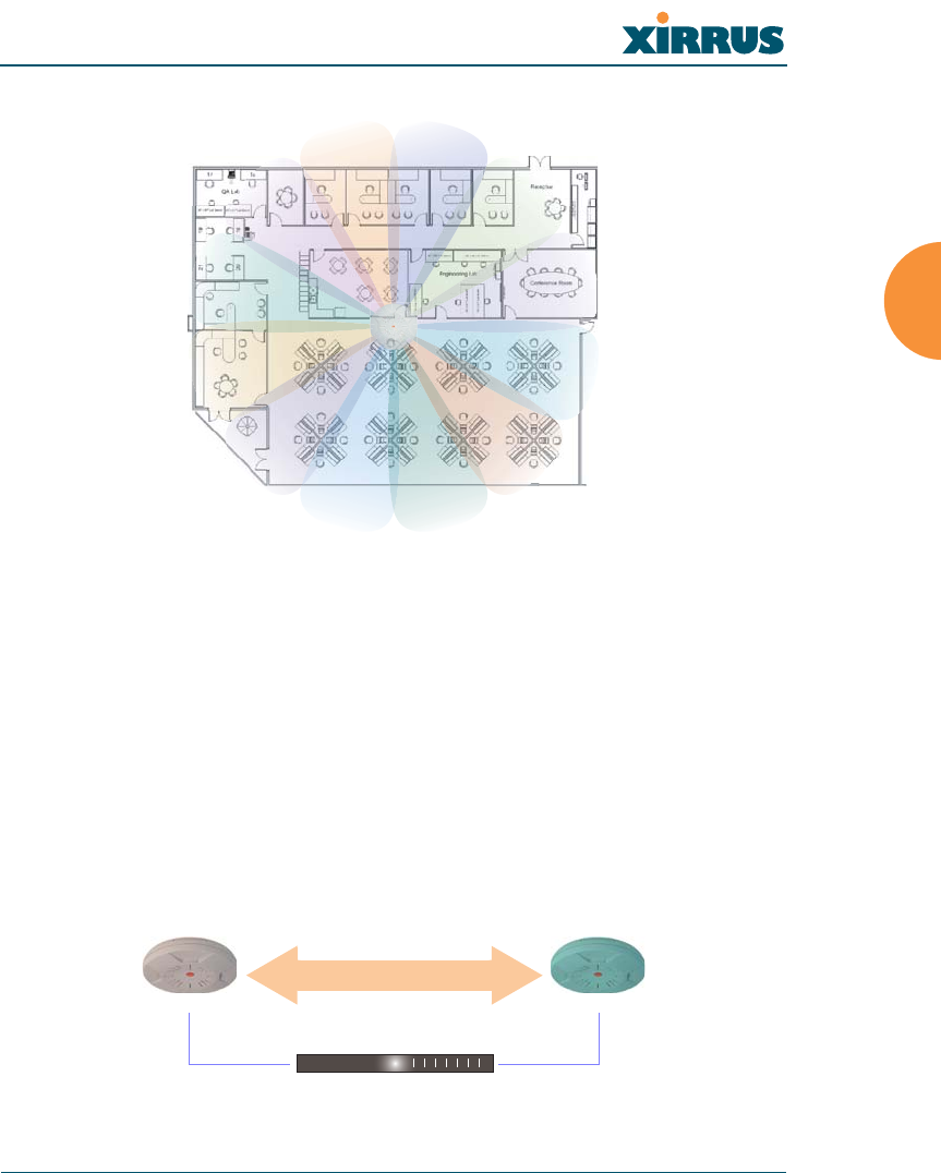
Wireless LAN Array
Installing the XS-3900 29
Figure 20. Deployment Scenario (18 Mbps)—Per Sector
Failover Planning
This section discusses failover protection at the unit and port levels.
Unit Failover Protection
In the rare event that an XS-3900 becomes unavailable, it is suggested that you
deploy a backup unit. Backup units monitor primary units via an Ethernet switch
and continue to provide wireless services in the event that the primary unit
becomes unavailable. Any XS-3900 can be set up as a backup unit. Backup units
should be located near primary units.
Figure 21. Unit Failover Protection
Primary
Active mode Offline mode until needed
Backup
heartbeat monitor
Ethernet switch

Wireless LAN Array
30 Installing the XS-3900
Port Failover Protection
To ensure that service is continued in the event of a port failure, you can utilize all
three XS-3900 ports (Fast Ethernet, Gigabit 1 and Gigabit 2) simultaneously.
Figure 22. Port Failover Protection
Switch Failover Protection
To ensure that service is continued in the event of a switch failure, you can
connect XS-3900 units to more than one Ethernet switch.
Figure 23. Switch Failover Protection
#Gigabit Ethernet connections must be on the same subnet.
Ethernet switch
Multiple port connections
Ethernet switch Backup switch
Ethernet connections

Wireless LAN Array
Installing the XS-3900 31
Power Planning
This section discusses the AC and DC power options.
AC Power
The AC power option requires a direct connection between the XS-3900 and a
dedicated AC power outlet. The power cord is provided with the unit.
Remote Distributed DC Power
To deliver DC power to the XS-3900, you must have the optional Xirrus Remote
DC Power System (XP-3100) and a Xirrus Array that supports DC power—see
Figure 4 on page 8 . The XP-3100 provides DC power to multiple XS-3900 units
from a single source, and requires only one AC power outlet.
Depending on the type of cable used, XS-3900 units can be located up to 600 feet
from the XP-3100. In addition, the XP-3100 can be plugged into a UPS to prevent
power failure to all XS-3900 units in the network.
When using CAT5 cable, DC power can be provided up to a distance of 300 feet.
Security Planning
This section offers some useful guidelines for defining your preferred encryption
and authentication method. For additional information, go to the Security section
of “Frequently Asked Questions” on page 186.
Wireless Encryption
Encryption ensures that no user can decipher another user’s data transmitted
over the airwaves. There are three encryption options available to you, including:
zWEP-40bit or WEP-128bit
Because WEP is vulnerable to cracks, we recommend that you only use
this for legacy devices that cannot support a stronger encryption type.
zWi-Fi Protected Access
This is much more secure than WEP and uses TKIP for encryption.

Wireless LAN Array
32 Installing the XS-3900
zWi-Fi Protected Access 2
This is government-grade encryption—available on most new client
adapters—and uses the AES–CCM encryption mode (Advanced
Encryption Standard–Counter Mode).
Authentication
Authentication ensures users are who they say they are, and occurs when users
attempt to join the wireless network and periodically there after. The following
authentication methods are available with the XS-3900:
zRADIUS 802.1x
802.1x uses a remote RADIUS server to authenticate large numbers of
clients, and can handle different authentication methods (EAP-TLS, EAP-
TTLS EAP-PEAP).
zXirrus internal RADIUS server
Includes all the core functionality of a full RADIUS server built into the
Xirrus XS-3900. Recommended for smaller numbers of users (about 100
or less).
zPre-Shared Key
Uses a pass-phrase or key that is manually distributed to all authorized
users. The same passphrase is given to client devices and entered into
each Xirrus array.
zMAC Access Control Lists (ACLs)
MAC access control lists provide a list of client adapter MAC addresses
that are allowed or denied access to the wireless network, and can be
used in addition to any of the above authentication methods. ACLs are
good for embedded devices, like printers and bar-code scanners (though
MAC addresses can be spoofed). The XS-3900 supports 512 ACL entries.

Wireless LAN Array
Installing the XS-3900 33
Network Management Planning
Network management can be performed using any of the following methods:
zCommand Line Interface, using an SSH (Secure Shell) utility, like PuTTY.
zWeb-based management, using the XS-3900 unit’s embedded Web
Management Interface (WMI). This method provides configuration and
basic monitoring tools, and is good for small deployments (one or two
units).
zWeb-based management, using the optional Xirrus Wireless
Management System (XM-3300). The XM-3300 is used for managing large
XS-3900 deployments from a centralized Web-based interface and offers
the following features:
Layer 3 appliance
Globally manage large numbers of XS-3900 units
Seamless view of the entire wireless network
Easily configure large numbers of XS-3900 units
Rogue AP monitoring
Easily manage system-wide firmware updates
Monitor performance and trends
Aggregation of alerts and alarms

Wireless LAN Array
34 Installing the XS-3900
Deployment Summary
The following table summarizes your deployment options for small and large
deployments.
Function Number of XS-3900 Units
One or Two Three or More
Power AC
DC (with XP-3100)
AC
DC (with XP-3100)
UPS backup
(recommended)
Failover Recommended Highly recommended
VLANs Optional
Required for guest access
Optional use,
Can be used to put all
APs on one VLAN or
map to existing VLAN
scheme
Required for Guest
Access
Encryption WPA with TKIP
(recommended)
PSK or 802.1x
WPA2 with AES
(recommended)
802.1x keying
Authentication Internal RADIUS server
Pre-Shared Key
External RADIUS server
Management Internal WMI
Internal CLI
XM-3300
XM-3300

Wireless LAN Array
Installing the XS-3900 35
Installation Workflow
This workflow illustrates the steps that are required to install and configure the
XS-3900 successfully. Review this flowchart before attempting to install the unit
on a customer’s network.
Figure 24. Installation Workflow
Determine the number of Arrays needed
Choose the location(s) for your XS-3900 unit(s)
AC DC
Install the mounting plate
Connect the cables and turn on the power
Verify that the Ethernet link and radio LEDs are functioning correctly
Perform the Express Setup procedure
Run AC power and Ethernet cables Run DC power and Ethernet cables
AC or DC
power?

Wireless LAN Array
36 Installing the XS-3900
Unpacking the XS-3900
When you unpack your XS-3900, you will find the following items in the carton:
Item Quantity
Xirrus Wireless LAN Array (XS-3900) module 1
AC power cord 1
Mounting plate 1
Mounting screws 4
Screw anchors 4
Tile grid mounting clamps 4
Clamp nuts 4
Mounting template 1
End User License Agreement (EULA) 1
CD-ROM containing:
This User’s Guide in PDF format
README file
1
Quick Install Guide 1
Registration Card 1

Wireless LAN Array
Installing the XS-3900 37
Installing the XS-3900
This section provides instructions for installing the XS-3900 unit.
Choosing a Location
Based on coverage, capacity and deployment examples discussed earlier in this
chapter, choose a location for your XS-3900 that will provide the best results for
your needs. The XS-3900 was designed to be mounted on a ceiling where the unit
is unobtrusive and wireless transmissions can travel unimpeded throughout open
plan areas. Choose a location that is central to your users.
Wiring Considerations
Unless you are using the Xirrus Remote DC Power System (XP-3100) with the DC
version of the XS-3900, an AC power outlet must be available to the XS-3900 (an
AC power cord is provided with each unit). If you are using the XP-3100 to
distribute DC power to multiple XS-3900 units, go to “Remote DC Power System
(Optional)” on page 8.
Once you have determined the best location for your XS-3900, you must run
cables to the location for the following services:
Power
zDedicated AC power
zDC power (if using the XP-3100)
Network
zGigabit 1
zGigabit 2 (optional)
zFast Ethernet (optional)
zSerial cable (see note)
#When the unit’s IP address is unknown or a network connection has not been
established, the serial cable is used for connecting directly with the Command
Line Interface (CLI) via HyperTerminal. When a network connection is
established, the XS-3900 can be managed from any of the available network
connections, either Fast Ethernet, Gigabit 1 or Gigabit 2.

Wireless LAN Array
38 Installing the XS-3900
Mounting the Unit
Most offices have drop-down acoustical ceiling tiles set into a standard grid. The
XS-3900 has been designed to enable mounting to a tiled ceiling via a mounting
plate and clamps that attach to the grid. Once the mounting plate is attached, the
XS-3900 simply rotates onto the plate (similar to a smoke detector). Once the unit
is mounted it can be removed and re-attached easily, without the need for tools or
modifications to the original installation.
This section assumes that you are mounting the XS-3900 to a tiled ceiling. If your
ceiling is not tiled, the mounting plate can be attached directly to the ceiling with
the screws and anchors provided (without using the tile grid mounting clamps).

Wireless LAN Array
Installing the XS-3900 39
Attaching the T-Bar Clips
The T-bar clips are used to create four mounting points on the ceiling tile grid for
the XS-3900 mounting plate. Use the mounting template (provided) to find the
correct location for all four clamps. To attach the clamps, simply twist the clamps
onto the grid and tighten the screw post with a screwdriver.
Figure 25. Attaching the T-Bar Clips
Ceiling tile grid
T-bar clips (4 places)
Tighten the screw post
Template
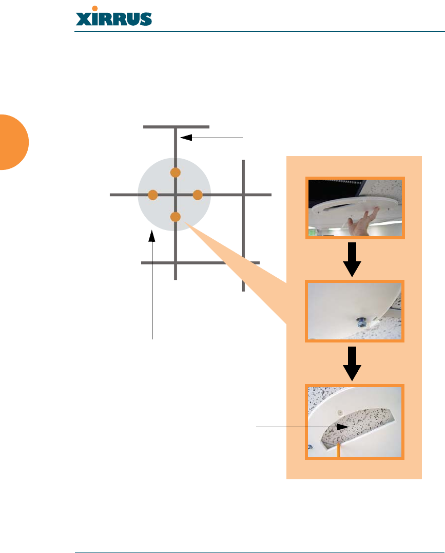
Wireless LAN Array
40 Installing the XS-3900
Installing the Mounting Plate
If necessary, orient the mounting plate (see “Attaching the T-Bar Clips” on
page 39) and locate the plate on the four screw posts. Secure the mounting plate
to the four clamps using the nuts provided. Once the mounting plate is secured,
cut an access hole in the ceiling tile for the cables.
Figure 26. Installing the Mounting Plate
Tile grid
Mounting Plate
Cut an access hole here
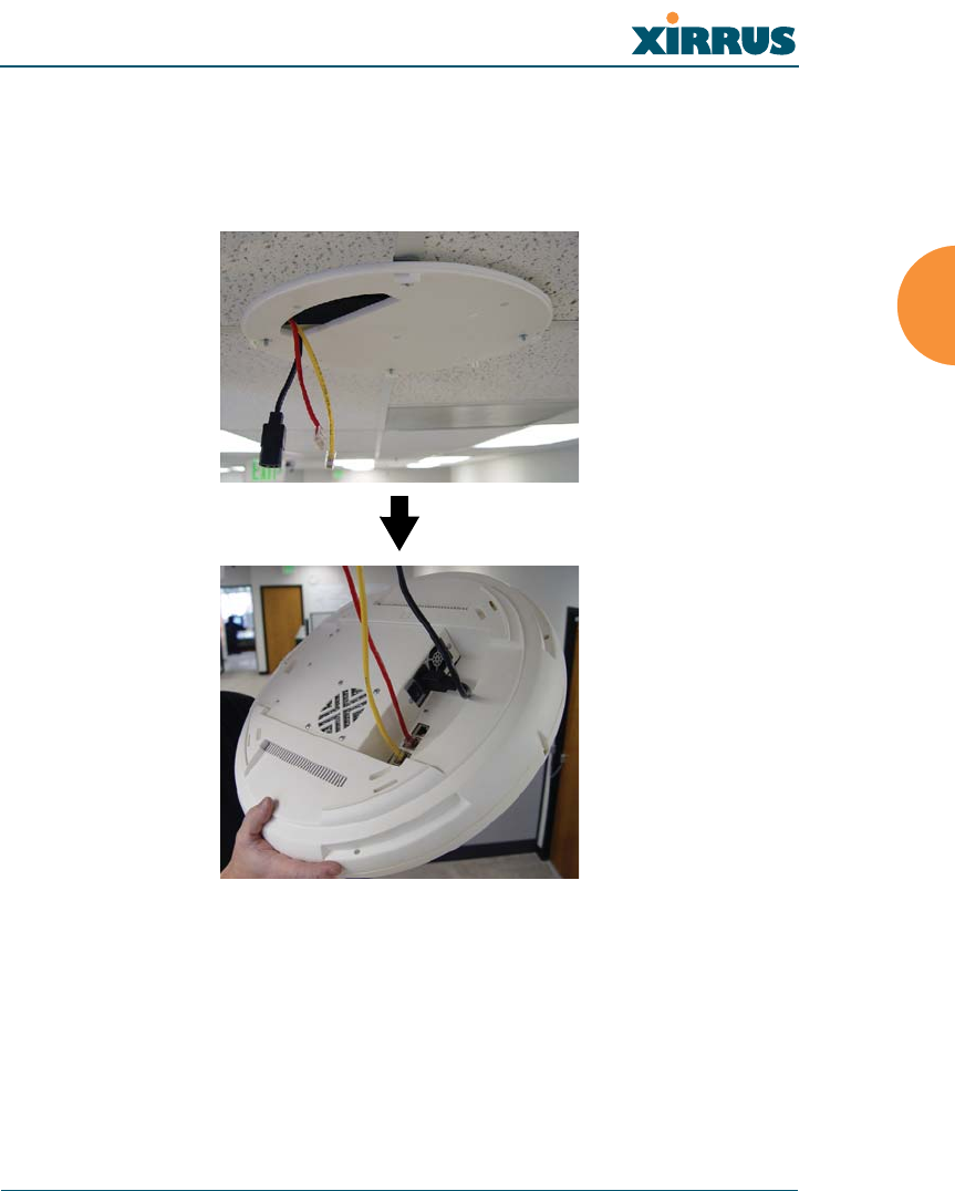
Wireless LAN Array
Installing the XS-3900 41
Connecting the Cables
Feed the power and Ethernet cables through the access hole in the tile and the
mounting plate, then connect the cables to the unit. See also, “Wiring
Considerations” on page 37.
Figure 27. Connecting the Cables
When the cables are connected, turn on the power switch—before attaching the
unit to the mounting plate (next step). Verify that the Ethernet link LED lights and
the LED boot sequence begins. The radio LEDs on the front of the unit will
illuminate in rotation, indicating that the XS-3900 software is loading and the unit
is functioning correctly.

Wireless LAN Array
42 Installing the XS-3900
Attaching the Array to the Mounting Plate
Align the port recess on the XS-3900 with the access hole in the mounting plate,
then connect the XS-3900 with the lugs on the mounting plate (4 places) and turn
the XS-3900 clockwise to lock the unit into place (similar to a smoke detector).
Figure 28. Attaching the Unit
For added security, there is a locking bracket incorporated into the mounting
plate, which will accept a small luggage-style padlock (if desired). There is also a
Kensington lock slot located near the Ethernet ports. In addition, the mounting
plate incorporates a positive locking tab that prevents the unit from being
inadvertently released.

Wireless LAN Array
Installing the XS-3900 43
Now that the XS-3900 is physically installed, you must run the Express Setup
procedure from the unit’s Web Management Interface to enable the radios and
establish initial system configuration settings. Go to “Powering Up the XS-3900”
on page 44.
Dismounting the Array
To dismount the array, place your fingers so as to increase the space between the
array and the mounting plate at the positions indicated by the decals on the
mounting plate—these are aligned with IAPs (radios) abg1 and abg3, as indicated
on the clock-face of the array.
Figure 29. IAP (Radio) Positions
a1
abg1
a2
a3
a4
abg2
a5
a6
a7
abg3
a8
a9
a10
abg4
a11
a12

Wireless LAN Array
44 Installing the XS-3900
Powering Up the XS-3900
When powering up, the array follows a specific sequence of LED patterns
showing the boot progress, and following a successful boot will provide extensive
status information. The normal boot sequence is as follows:
1. The green status LED will light first, showing a steady flashing while the
unit boots. In the event of a boot failure, this LED will change to flashing
red.
2. The Ethernet Link/Activity LEDs on the underside of the array will light
for those ports connected to the network.
3. All IAP radio LEDs will light simultaneously.
4. While the array is booting, a sequential LED pattern will cycle through all
the radio LEDs.
5. When the array completes boot, the status LED will show a steady green,
and all radio lights will show the current state of those radios.
Figure 30. LED Locations
Status LED
IAP LEDs (x16)
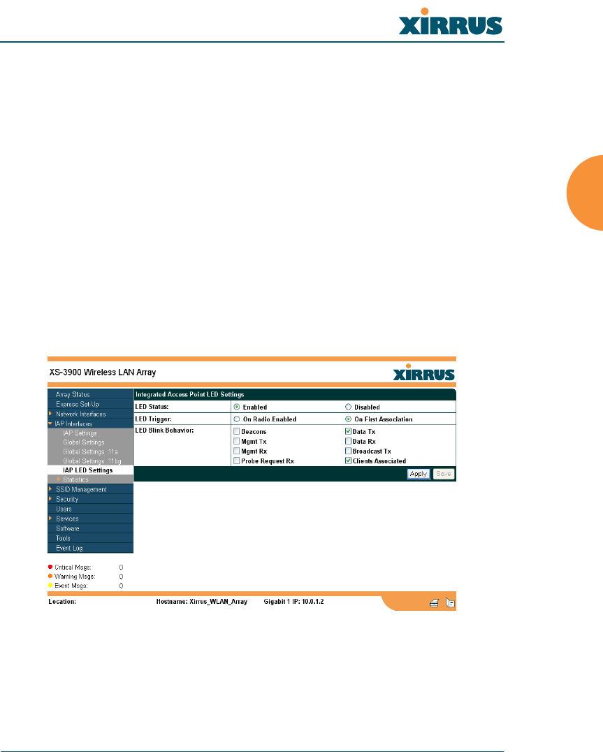
Wireless LAN Array
Installing the XS-3900 45
Once the unit is fully booted the default IAP LED display will be as follows:
zIAP radio LEDs that are enabled will show a steady orange for 802.11a
radios, or green for 802.11b/g radios.
zOnce a client associates with an individual IAP, that LED will show a
slow flash (heartbeat) pattern.
zWhen data is transmitted or received by an IAP, that IAP’s LED will
flash. The rate of flashing changes with the number of packets sent or
received per second—the LED will flash more quickly with a greater
number of packets per second and more slowly with lower numbers of
packets per second.
These settings may be altered or disabled entirely for diagnostic purposes or for
personal preference. Changes are made via the array’s Command Line Interface
or the Web Management Interface—refer to “IAP LED Settings” on page 88.
Figure 31. WMI: IAP LED Settings Page

Wireless LAN Array
46 Installing the XS-3900
Establishing Communication with the Array
The XS-3900 can be configured through the Command Line Interface (CLI) or the
graphical Web Management Interface (WMI). You can use the CLI via the serial
management port, the Fast Ethernet port, or either of the Gigabit Ethernet ports.
You can use the WMI via any of the array’s Ethernet ports.
Figure 32. Network Interface Ports
Using the Serial Port
If using the serial port to make your connection, use serial settings of 8 bits, no
parity, 1 stop bit (8N1) and a speed setting of 115200 baud. Use the
communication package of your choice.
Using the Ethernet Ports
If the array is booted and does not receive DHCP addresses on either the Fast
Ethernet or Gigabit Ethernet ports, the Fast Ethernet port will default to an IP
address of 10.0.0.1 and both Gigabit Ethernet ports will default to 10.0.1.2.
If the array is connected to a network that provides DHCP addresses, the IP
address can be determined by the following two methods:
1. Examine the DHCP tables on the server and find the addresses assigned
to the array (Xirrus MAC addresses begin with 000F7D).
2. Query the array using the CLI via the serial port. Use the show summary
ethernet command to view the IP addresses assigned to each port.
Logging In
When logging in to the array, use the default user name and password (the
default for both is admin).
Serial
Fast Ethernet
Gigabit 1
Gigabit 2

Wireless LAN Array
Installing the XS-3900 47
Performing the Express Setup Procedure
The Express Setup procedure allows you to establish global configuration settings
that will enable basic XS-3900 functionality. Any changes you make on this page
will affect all radios. When finished, click on the Apply button to apply the new
settings to this session, then click on the Save button to save your changes.
Figure 33. WMI: Express Setup Page (Part 1)
more ...

Wireless LAN Array
48 Installing the XS-3900
Figure 34. WMI: Express Setup Page (Part 2)
Procedure for Performing an Express Setup
1. Host Name: Specify a unique host name for this XS-3900 unit. The host
name is used to identify the XS-3900 on the network. Use a name that will
be meaningful within your network environment, up to 64 alphanumeric
characters.
2. Location Information: Enter a brief but meaningful description that
accurately defines the physical location of this XS-3900 unit. In an
environment where multiple units are installed, clear definitions for their
locations are important if you want to identify a specific unit.
3. Admin Contact: Enter the name and contact information of the person
who is responsible for administering this XS-3900 unit at the designated
location.
4. Country of Operation: To ensure that the array remains in compliance
with local regulatory laws, the Country of Operation is set at the factory
and cannot be changed.
5. IAP Status: This option provides a button that allows you to enable all
radios. Simply click on the Enable All Radios button to enable all radios
for this Wireless LAN Array.
... continued

Wireless LAN Array
Installing the XS-3900 49
6. Configure the Fast Ethernet, Gigabit 1 and Gigabit 2 network interfaces.
The fields for each of these interfaces are the same, and include:
a. MAC Address: This field displays the hardware MAC address for the
network interface and cannot be changed.
b. Enable Interface: Choose Yes to enable this network interface, or
choose No to disable the interface.
c. Allow Management on Interface: Choose Yes to allow management
of the array via this network interface, or choose No to deny all
management privileges for this interface.
d. Configuration Server Protocol: Choose DHCP to instruct the array
to use DHCP to assign IP addresses to the array’s Ethernet interfaces,
or choose Static IP if you intend to enter IP addresses manually. If
you choose the Static IP option, you must enter the following
information:
zIP Address: Enter a valid IP address for this array. To use
any of the remote connections (Web, SNMP, or SSH), a valid
IP address must be used.
zIP Subnet Mask: Enter a valid IP address for the subnet
mask (the default is 255.255.255.0). The subnet mask defines
the number of IP addresses that are available on the routed
subnet where the array is located.
zDefault Gateway: Enter a valid IP address for the default
gateway. This is the IP address of the router that the array
uses to forward data to other networks.
7. SSID (Wireless Network Name): Enter a unique SSID, up to 32
characters. The SSID (Service Set Identifier) is a unique name that
identifies a wireless network. All devices attempting to connect to a
specific WLAN must use the same SSID. The default is “xirrus.”
For additional information about SSIDs, go to the Multiple SSIDs section
of “Frequently Asked Questions” on page 186.

Wireless LAN Array
50 Installing the XS-3900
8. Wireless Security: Select the desired wireless security scheme (WEP or
WPA). Make your selection from the choices available in the pull-down
list.
WEP (Wired Equivalent Privacy)
An optional IEEE 802.11 function that offers frame transmission
privacy similar to a wired network. WEP generates secret shared
encryption keys that both source and destination stations can use to
alter frame bits to avoid disclosure to eavesdroppers.
WPA (Wi-Fi Protected Access)
A Wi-Fi Alliance standard that contains a subset of the IEEE 802.11i
standard, using TKIP or AES as an encryption method and 802.1X for
authentication. WPA is the stronger of the two wireless security
schemes.
For more information about security, including a full review of all
security options and settings, go to “Security Management” on page 98.
9. Wireless Key/Passphrase: Depending on the wireless security scheme
you selected, enter a unique WEP key or WPA passphrase.
a. Confirm Key/Passphrase: If you entered a WEP key or WPA
passphrase, confirm it here.
10. New Admin Password: If desired, enter a new administration password
for managing this array. Choose a password that is not obvious, and one
that you can remember. If you forget your password, you must reset the
array to its factory defaults so that the password is reset to admin (its
default setting).
a. Confirm Admin Password: If you entered a new administration
password, confirm the new password here.
#Security settings will only take effect if they are assigned to a specific
SSID. Refer to “SSID Management” on page 92.

Wireless LAN Array
Installing the XS-3900 51
11. Adjust Time (hrs:min:sec): Check this box if you want to adjust the
current system time. When the box is checked, the time fields become
active. Enter the revised time (hours, minutes, seconds, am/pm) in the
corresponding fields. If you don’t want to adjust the current time, this
box should be left unchecked (default).
12. Adjust Date (day/month/year): Check this box if you want to adjust the
current system date. When the box is checked, the date fields become
active. Enter the revised date (day, month, year) in the corresponding
fields. If you don’t want to adjust the current date, this box should be left
unchecked (default).
13. Auto Adjust Daylight Savings: Check this box if you want the system to
adjust for daylight savings automatically, otherwise leave this box
unchecked (default).
14. Use NTP (IP Address): Check this box if you want to use an NTP
(Network Time Protocol) server to synchronize the array’s clock. This
ensures that syslog time-stamping is maintained across all units. Without
an NTP server assigned (no universal clock), each array will use its own
internal clock and stamp times accordingly, which may result in
discrepancies. When this box is checked, the NTP and NTP 2 IP address
fields become active. If you don’t want to use an NTP server, leave this
box unchecked (default), otherwise enter the IP address or DNS name of
the NTP server.
Figure 35. Enabling the NTP Feature
a. NTP 2 (IP Address): If you enabled the NTP option and the site is
using a secondary NTP server, enter the IP address or DNS name of
the secondary NTP server.
NTP enabled

Wireless LAN Array
52 Installing the XS-3900
15. Click on the Apply button to apply the new settings to this session
16. Click on the Save button to save your changes (otherwise your new
settings will not take effect).
This ends the Express Setup procedure.

Wireless LAN Array
The Web Management Interface 53
The Web Management Interface
This chapter provides an overview of the XS-3900’s embedded Web Management
Interface (WMI), used for establishing your network’s configuration settings and
wireless operating parameters. Section headings for this chapter include:
zAn Overview
An Overview
The WMI is an easy-to-use graphical interface to your XS-3900. It allows you to
configure the product to suit your individual requirements and ensure that the
unit functions efficiently and effectively.
Figure 36. Web Management Interface

Wireless LAN Array
54 The Web Management Interface
Content
The content of the WMI has been organized by function and hierarchy, shown
here in list form. You can click on any item in the list to jump to the referenced
destination.
Array Status
Express Setup
Network Interfaces
Network Settings
VLAN Settings
Network Statistics
DHCP Server Settings
DNS Settings
IAP Interfaces
IAP Settings
Global Settings
Global Settings .11a
Global Settings .11bg
IAP LED Settings
SSID Management
Create SSID
Edit SSID
Security
Security Management
Radius Server
Radius User
MAC Access List
Create Admin
Edit Admin
Users
Services
System Log
SNMP
Software
Tools
Event Log

Wireless LAN Array
The Web Management Interface 55
Structure
The WMI has been designed with simplicity in mind, making navigation quick
and easy. In the following example, you’ll see that pages are divided into left and
right frames. The left frame contains configuration elements organized by
function (for example, radio interfaces, security, etc.), and where these functions
are sub-divided there is an associated pull-down menu. Also included in the left
frame are three counters that provide a running total of messages generated by
the syslog subsystem during your session—organized into Critical, Warning and
Event messages.
Figure 37. WMI: Frames
The right frame contains the configuration parameters for the XS-3900. This is
where you input data (if you want to make changes) or review the XS-3900’s
current status and activity.
Left frame Right frame
Message counters
Pull-down menu

Wireless LAN Array
56 The Web Management Interface
Status Bar
Below the configuration frames you will find a status bar containing information
about this XS-3900 unit, including:
zLocation—displays the location information assigned to the unit.
zHost name—the host name assigned to this unit.
zNetwork interface IP address—the IP address of the network interface
that is currently being used.
Also included in the status bar is a Print button and a Help button. Click on the
Print button to send a print file of the active page to your local printer, or click on
the Help button to go to the XS-3900’s online help system.
Figure 38. WMI: Status Bar
Applying Configuration Changes
When you have defined all your settings on any WMI configuration page, you
must click on the Apply button for the changes to take effect in the current
session. Click on the Save button to write your changes (for future sessions).
Character Restrictions
When inputting strings in the WMI (for example, assigning SSIDs, host name,
password, etc.), use only common alphanumeric characters. Do not use any of the
following characters:
&<>' “/ \
Status information
Print button
Help button

Wireless LAN Array
Configuring the XS-3900 57
Configuring the XS-3900
This chapter covers configuration and management tasks using the product’s
embedded Web Management Interface (WMI). It also includes a procedure for
logging in to the XS-3900 with your Web browser. Section headings for this
chapter include:
zLogging In
zMaking Configuration Changes to the XS-3900
Logging In
Use this procedure to log in to the WMI via your Web browser.
1. Establish a network connection and open your Web browser.
2. Connect to the XS-3900 via its default IP address (10.0.1.1).
3. When connected to the XS-3900, a login prompt appears on your screen.
The default login user name and password is admin (for both). Login
names and passwords are case-sensitive.
4. To log in to the XS-3900’s Web Management Interface, enter admin when
prompted for a user name and password.
Figure 39. WMI: Logging In to the XS-3900

Wireless LAN Array
58 Configuring the XS-3900
Making Configuration Changes to the XS-3900
This section has been organized into functional areas that reflect the flow and
content of the WMI. Configuration instructions to the XS-3900 require you to
input data in one or more of the following formats:
zSpecifying data (for example, IP addresses, descriptions, etc.).
zMaking selections from pull-down lists.
zChoosing an option by clicking on a radio button (for example, on/off).
zClicking on a check box to activate/deactivate a feature.
zClicking on a button to confirm a command or apply your changes.
Array Status
This is a status only page that provides a snapshot of the global configuration
settings for all XS-3900 network interfaces and radios. You must go to the
appropriate configuration page to make changes to any of the settings displayed
here (configuration changes cannot be made from this page).
Figure 40. WMI: Array Status Page

Wireless LAN Array
Configuring the XS-3900 59
The Array Status page is sub-divided into the Network Interface and IAP
Interface (radio) sections and provides you with the following information:
zAll devices: A listing of the available Network Interfaces and IAPs with
each item containing a link to the associated configuration page. Linked
items are shown UNDERLINED. For example:
Figure 41. Linked Items
zAll devices: The current status of each device, whether enabled or
disabled. Devices that are disabled are shown in RED. For example:
Figure 42. WMI: Disabled Device (Partial View)
zNetwork Interface devices:
zThe Management column indicates whether the network interface
device is enabled or disabled. Network interfaces are enabled or
disabled on the Network Settings page.
zThe Configuration column shows how each network interface
obtains its IP address—either dynamically via DHCP or entered
manually by you (static configuration) on the Network Settings page.
These items
are linked
Disabled devices are shown in RED
Wireless LAN Array
60 Configuring the XS-3900
zThe IP Address column shows the current IP address being used by
each network interface device.
zIAP Interface devices:
zThe Channel column shows on which channel each IAP (radio) is
operating. Channel selections are made on the IAP Settings page
from a pull-menu. To avoid co-channel interference, adjacent radios
should not be using adjacent channels.
zThe Cell Size column indicates which cell size setting is currently
active for each radio—either small, medium, large or manually
defined by you. The cell size of a radio is a function of its transmit
power and determines the radio’s overall coverage. Cell sizes are
defined on the IAP Settings page. For additional information about
cell sizes and the importance of planning for and defining the
optimum sizes for your array, go to “Coverage and Capacity
Planning” on page 21.
Figure 43. IAP Cells
zThe Associated Users column informs you how many users are
currently associated with each radio. The high-capacity XS-3900 can
handle up to 64 concurrent users per individual IAP radio (or 960
users per array).

Wireless LAN Array
Configuring the XS-3900 61
Express Setup
This page allows you to establish global configuration settings that will enable
basic XS-3900 functionality. Any changes you make on this page will affect all
radios. When finished, click on the Apply button to apply the new settings to this
session, then click on the Save button to save your changes.
Figure 44. WMI: Express Setup Page (Part 1)
more ...

Wireless LAN Array
62 Configuring the XS-3900
Figure 45. WMI: Express Setup Page (Part 2)
Procedure for Performing an Express Setup
1. Host Name: Specify a unique host name for this XS-3900 unit. The host
name is used to identify the XS-3900 on the network. Use a name that will
be meaningful within your network environment, up to 64 alphanumeric
characters.
2. Location Information: Enter a brief but meaningful description that
accurately defines the physical location of this XS-3900 unit. In an
environment where multiple units are installed, clear definitions for their
locations are important if you want to identify a specific unit.
3. Admin Contact: Enter the name and contact information of the person
who is responsible for administering this XS-3900 unit at the designated
location.
4. Country of Operation: To ensure that the array remains in compliance
with local regulatory laws, the Country of Operation is set at the factory
and cannot be changed.
5. IAP Status: This option provides a button that allows you to enable all
radios. Simply click on the Enable All Radios button to enable all radios
for this Wireless LAN Array.
... continued

Wireless LAN Array
Configuring the XS-3900 63
6. Configure the Fast Ethernet, Gigabit 1 and Gigabit 2 network interfaces.
The fields for each of these interfaces are the same, and include:
a. MAC Address: This field displays the hardware MAC address for the
network interface and cannot be changed.
b. Enable Interface: Choose Yes to enable this network interface, or
choose No to disable the interface.
c. Allow Management on Interface: Choose Yes to allow management
of the array via this network interface, or choose No to deny all
management privileges for this interface.
d. Configuration Server Protocol: Choose DHCP to instruct the array
to use DHCP to assign IP addresses to the array’s Ethernet interfaces,
or choose Static IP if you intend to enter IP addresses manually. If
you choose the Static IP option, you must enter the following
information:
zIP Address: Enter a valid IP address for this array. To use
any of the remote connections (Web, SNMP, or SSH), a valid
IP address must be used.
zIP Subnet Mask: Enter a valid IP address for the subnet
mask (the default is 255.255.255.0). The subnet mask defines
the number of IP addresses that are available on the routed
subnet where the array is located.
zDefault Gateway: Enter a valid IP address for the default
gateway. This is the IP address of the router that the array
uses to forward data to other networks.
7. SSID (Wireless Network Name): Enter a unique SSID, up to 32
characters. The SSID (Service Set Identifier) is a unique name that
identifies a wireless network. All devices attempting to connect to a
specific WLAN must use the same SSID. The default is “xirrus.”
For additional information about SSIDs, go to the Multiple SSIDs section
of “Frequently Asked Questions” on page 186.

Wireless LAN Array
64 Configuring the XS-3900
8. Wireless Security: Select the desired wireless security scheme (WEP or
WPA). Make your selection from the choices available in the pull-down
list.
WEP (Wired Equivalent Privacy)
An optional IEEE 802.11 function that offers frame transmission
privacy similar to a wired network. WEP generates secret shared
encryption keys that both source and destination stations can use to
alter frame bits to avoid disclosure to eavesdroppers.
WPA (Wi-Fi Protected Access)
A Wi-Fi Alliance standard that contains a subset of the IEEE 802.11i
standard, using TKIP or AES as an encryption method and 802.1X for
authentication. WPA is the stronger of the two wireless security
schemes.
For more information about security, including a full review of all
security options and settings, go to“Security Management” on page 98.
9. Wireless Key/Passphrase: Depending on the wireless security scheme
you selected, enter a unique WEP key or WPA passphrase.
a. Confirm Key/Passphrase: If you entered a WEP key or WPA
passphrase, confirm it here.
10. New Admin Password: If desired, enter a new administration password
for managing this array. Choose a password that is not obvious, and one
that you can remember. If you forget your password, you must reset the
array to its factory defaults so that the password is reset to admin (its
default setting).
a. Confirm Admin Password: If you entered a new administration
password, confirm the new password here.
11. Adjust Time (hrs:min:sec): Check this box if you want to adjust the
current system time. When the box is checked, the time fields become
active. Enter the revised time (hours, minutes, seconds, am/pm) in the
corresponding fields. If you don’t want to adjust the current time, this
box should be left unchecked (default).

Wireless LAN Array
Configuring the XS-3900 65
12. Adjust Date (day/month/year): Check this box if you want to adjust the
current system date. When the box is checked, the date fields become
active. Enter the revised date (day, month, year) in the corresponding
fields. If you don’t want to adjust the current date, this box should be left
unchecked (default).
13. Auto Adjust Daylight Savings: Check this box if you want the system to
adjust for daylight savings automatically, otherwise leave this box
unchecked (default).
14. Use NTP (IP Address): Check this box if you want to use an NTP
(Network Time Protocol) server to synchronize the array’s clock. This
ensures that syslog time-stamping is maintained across all units. Without
an NTP server assigned (no universal clock), each array will use its own
internal clock and stamp times accordingly, which may result in
discrepancies. When this box is checked, the NTP and NTP 2 IP address
fields become active. If you don’t want to use an NTP server, leave this
box unchecked (default), otherwise enter the IP address or DNS name of
the NTP server.
Figure 46. Enabling the NTP Feature
a. NTP 2 (IP Address): If you enabled the NTP option and the site is
using a secondary NTP server, enter the IP address or DNS name of
the secondary NTP server.
15. Click on the Apply button to apply the new settings to this session
16. Click on the Save button to save your changes (otherwise your new
settings will not take effect).
This ends the Express Setup procedure.
NTP enabled

Wireless LAN Array
66 Configuring the XS-3900
Network Interfaces
This is a status only page that provides a snapshot of the configuration settings
currently established for the 10/100 Fast Ethernet interface and the 10/100/1000
Gigabit 1 and Gigabit 2 interfaces. You must go to the appropriate configuration
page to make changes to any of the settings displayed here (configuration
changes cannot be made from this page).
You can click on any item in the Interface column to “jump” to the associated
configuration page.
Figure 47. WMI: Network Interfaces Page
WMI pages that allow you to change or view configuration settings associated
with the network interfaces include:
z“Network Settings” on page 67.
z“VLAN Settings” on page 71.
z“Network Statistics” on page 74.
z“DHCP Server Settings” on page 75.
z“DNS Settings” on page 76.

Wireless LAN Array
Configuring the XS-3900 67
Network Settings
This page allows you to establish configuration settings for the 10/100 Fast
Ethernet interface and the 10/100/1000 Gigabit 1 and Gigabit 2 interfaces.
When finished, click on the Apply button to apply the new settings to this
session, then click on the Save button to save your changes.
Figure 48. WMI: Network Settings Page (Part 1)
#Gigabit 2 settings will “mirror” Gigabit 1 settings (except for MAC addresses)
and cannot be configured separately.
more ...

Wireless LAN Array
68 Configuring the XS-3900
Figure 49. WMI: Network Settings Page (Part 2)
Network Interface Ports
The following diagram shows the location of each network interface port on the
underside of the XS-3900.
Figure 50. Network Interface Ports
... continued
Serial
Fast Ethernet
Gigabit 1
Gigabit 2

Wireless LAN Array
Configuring the XS-3900 69
Procedure for Configuring the Network Interfaces
1. Configure the Fast Ethernet, Gigabit 1 and Gigabit 2 network interfaces.
The fields for each of these interfaces are the same, and include:
a. MAC Address: This field shows the MAC address for this array. The
MAC (hardware) address is used to identify the Xirrus array to the
wired network. The MAC address is a static value and cannot be
changed.
b. Enable Interface: Choose Yes to enable this network interface (Fast
Ethernet, Gigabit 1 or Gigabit 2), or choose No to disable the
interface.
c. Allow Management on Interface: Choose Yes to allow management
of this array via the selected network interface, or choose No to deny
all management privileges for this interface.
d. Auto Negotiate: This feature allows the array to negotiate the best
transmission rates automatically. Choose Yes to enable this feature,
or choose No to disable this feature—the default is enabled. If you
disable the Auto Negotiate feature, you must define the Duplex and
Speed options manually (otherwise these options are not available).
zDuplex: Full-duplex refers to the transmission of data in two
directions simultaneously (for example, a telephone is a full-
duplex device because both parties can talk and be heard at
the same time). In contrast, half-duplex allows data
transmission in one direction at a time only (for example, a
walkie-talkie is a half-duplex device because it allows only
one party to talk at any one time). If the Auto-Negotiate
feature is disabled, you can manually choose Half or Full
duplex for your data transmission preference.
zSpeed: If the Auto-Negotiate feature is disabled, you can
manually choose the desired data transmission speed from
the pull-down list, either Fast Ethernet or Gigabit.

Wireless LAN Array
70 Configuring the XS-3900
e. MTU Size: Specify the MTU (Maximum Transmission Unit) size.
When you specify the MTU, you are defining—in bytes—the largest
physical packet size that the network can transmit. Any messages
larger than the MTU that you specify here are divided into smaller
packets before being sent. The default is 1000 bytes.
f. Encapsulation: Choose either dot1H (802.1H) or snap (SNAP) as the
Ethernet encapsulation type.
g. Configuration Server Protocol: Choose DHCP to instruct the XS-
3900 to use DHCP when assigning IP addresses to the array, or
choose Static IP if you intend to enter IP addresses manually.
zIP Address: If you selected the Static IP option, enter a valid
IP address for this XS-3900 unit. To use any of the remote
connections (Web, SNMP, or SSH), a valid IP address must
be established.
zIP Subnet Mask: If you selected the Static IP option, enter a
valid IP address for the subnet mask (the default for Class C
is 255.255.255.0). The subnet mask defines the number of IP
addresses that are available on the routed subnet where the
XS-3900 is located.
zDefault Gateway: If you selected the Static IP option, enter a
valid IP address for the default gateway. This is the IP
address of the router that the XS-3900 uses to transmit data to
other networks.
2. Click on the Apply button to apply the new settings to this session.
3. Click on the Save button to save your changes (otherwise your new
settings will not take effect).

Wireless LAN Array
Configuring the XS-3900 71
VLAN Settings
This page allows you to add or remove VLANs, associate VLANs to a specific
network interface, and enable VLAN tagging of outgoing traffic. When finished,
click on the Apply button to apply the new settings to this session, then click on
the Save button to save your changes.
Figure 51. WMI: VLAN Settings Page
Understanding VLANs
A VLAN (Virtual LAN) is a switch network that is logically segmented—by
functions, project teams, or applications rather than on a physical or geographical
basis. For example, all workstations and servers used by a particular workgroup
team can be connected to the same VLAN, regardless of their physical
connections to the network, or the fact that they might be intermingled with other
teams. You use VLANs to reconfigure the network through software rather than
physically unplugging and moving devices or wires.
A VLAN can be thought of as a broadcast domain that exists within a defined set
of switches. A VLAN consists of a number of end systems, either hosts or network
equipment (for example, bridges and routers), connected by a single bridging
domain.

Wireless LAN Array
72 Configuring the XS-3900
The bridging domain is supported on various pieces of network equipment, such
as LAN switches, that operate bridging protocols between them with a separate
group for each VLAN.
VLANs provide the segmentation services traditionally provided by routers in
LAN configurations. VLANs address scalability, security, and network
management. You should consider several key issues when designing and
building switched LAN networks:
zLAN segmentation
zSecurity
zBroadcast control
zPerformance
zNetwork management
zCommunication between VLANs
You extend VLANs into a wireless LAN by adding IEEE 802.11Q tag awareness to
the Xirrus array. Frames destined for different VLANs are transmitted by the
array wirelessly on different SSIDs. Conversely, packets coming from a client
associated with a certain VLAN are 802.11Q tagged before they are forwarded
onto the wired network.
Procedure for Configuring VLANs
1. New VLAN ID: Enter a new VLAN ID number (between 0 and 4012) that
matches your network’s VLAN scheme.
2. VLAN Description: Enter a meaningful description for this VLAN.
3. Tag Outgoing: Check this box if you want to enable VLAN tagging of
outgoing traffic.
4. Network Interface: Select the interface you want to associate to this
VLAN. Make your selection from the choices available in the pull-down
list—either Fast Ethernet, Gigabit 1 or Gigabit 2.

Wireless LAN Array
Configuring the XS-3900 73
5. VLAN Management: This list shows the VLANs that are currently
assigned to the array. Each time you create a VLAN, the new VLAN is
listed here. To delete a VLAN, select the VLAN from the list and click on
the Delete VLAN button.
6. Click on the Apply button to apply the new settings to this session.
7. Click on the Save button to save your changes (otherwise your new
settings will not take effect).
8. VLANs you defined can now be assigned to specific SSIDs.

Wireless LAN Array
74 Configuring the XS-3900
Network Statistics
This is a status only page that allows you to review statistical data associated with
each network interface and its activity. You can Refresh the data (update the page
with the latest information) or Clear the data (reset all content to zero and begin
counting again) at any time by clicking on the appropriate button. If you are
experiencing problems, you may also want to print this page for your records.
Figure 52. WMI: Network Statistics Page

Wireless LAN Array
Configuring the XS-3900 75
DHCP Server Settings
This page allows you to enable/disable DHCP (Dynamic Host Configuration
Protocol) server functionality. DHCP allows the array to provide wireless clients
with IP addresses and other networking information. The DHCP server will not
provide DHCP services to the wired side of the network.
If you enable the DHCP server, you need to define the DHCP lease time (default
and maximum) and establish the IP address range that the DHCP server can use.
When finished, click on the Apply button to apply the new settings to this
session, then click on the Save button to save your changes.
Figure 53. WMI: DHCP Settings Page
Procedure for Configuring the DHCP Server
1. Enable DHCP Server: Choose Yes to enable DHCP services, or choose
No to disable DHCP services.
2. Default Lease (seconds): This field defines the default DHCP lease time
(in seconds). The factory default is 300 seconds, but you can change the
default at any time.
3. Maximum Lease (seconds): Enter a value (in seconds) to define the
maximum allowable DHCP lease time. The default is 300 seconds.

Wireless LAN Array
76 Configuring the XS-3900
4. Starting IP Range: Enter an IP address to define the start of the IP range
that will be used by the DHCP server.
5. End IP Range: Enter an IP address to define the end of the IP range that
will be used by the DHCP server. The DHCP server will only use IP
addresses that fall between the start and end range that you define on this
page.
6. Click on the Apply button to apply the new settings to this session.
7. Click on the Save button to save your changes (otherwise your new
settings will not take effect).
DNS Settings
This page allows you to establish your DNS (Domain Name System) settings. At
least one DNS server must be set up if you want to offer clients associating with
this XS-3900 the ability to use meaningful host names instead of numerical IP
addresses. When finished, click on the Apply button to apply the new settings to
this session, then click on the Save button to save your changes.
Figure 54. WMI: DNS Settings Page

Wireless LAN Array
Configuring the XS-3900 77
Procedure for Configuring DNS Servers
1. DNS Host Name: Enter a valid DNS host name.
2. DNS Domain: Enter the DNS domain name.
3. DNS Server 1: Enter the IP address of the primary DNS server.
4. DNS Server 2: Enter the IP address of the secondary DNS server.
5. DNS Server 3: Enter the IP address of the tertiary DNS server.
6. Click on the Apply button to apply the new settings to this session.
7. Click on the Save button to save your changes (otherwise your new
settings will not take effect).

Wireless LAN Array
78 Configuring the XS-3900
IAP Interfaces
This is a status only page that allows you to review configuration data associated
with each Integrated Access Point (radio). It includes a list of which IAP radios
are enabled, the channel that each radio is currently using, cell sizes, and how
many users are currently associated with each radio. There are no configuration
options available on this page, but if you are experiencing problems or simply
reviewing the radio assignments, you may want to print this page for your
records.
You can click on any item in the IAP column to “jump” to the associated
configuration page.
Figure 55. WMI: IAP Interfaces Page

Wireless LAN Array
Configuring the XS-3900 79
IAP Settings
This page allows you to enable/disable Integrated Access Points (radios), define
the wireless mode for each radio, specify the channel to be used and the cell size
for each radio, establish transmit/receive parameters, and select antennas. When
finished, click on the Apply button to apply the new settings to this session, then
click on the Save button to save your changes. To see a diagram of the layout and
naming of radios, go to Figure 6 on page 10.
Figure 56. WMI: IAP Settings Page
Procedure for Auto Configuring IAPs (Radios)
You can auto-configure radios by clicking on the Auto Configure button on the
relevant WMI page (auto configuration only applies to enabled radios):
zFor all radios, go to the Global Settings page.
zFor all 802.11a radios, go to the Global Settings .11a page.
zFor all 802.11b/g radios, go to the Global Settings .11bg page.

Wireless LAN Array
80 Configuring the XS-3900
Procedure for Manually Configuring IAPs (Radios)
1. In the Enabled column, check the box of a corresponding radio to enable
the radio, or uncheck the box if you want to disable the radio.
2. In the Mode column, select the wireless mode for this
radio from the choices available in the pull-down
menu (either .11a or .11b/g).
3. In the Channel column, select the channel you want
this radio to use from the channels available in the
pull-down list.
The sample pull-down list shown here is for the abg2
radio with its mode set to .11b/g. Any channels
appearing in the list that are shown in RED are not
recommended.
4. In the Cell Size column, choose either Small,
Medium, or Large to define the desired pre-
configured cell size, or choose Manual to define the
wireless cell size manually. If you choose Manual,
you must specify the transmit and receive power—in dB—in the Tx
Power dB (transmit) and Rx dB (receive) fields.
The number of users and their applications are major drivers of
bandwidth requirements. The network architect must account for the
number of users within the XS-3900’s cell diameter.
In a large office, or where user density is high, you should choose Small
cells to achieve a higher data rate, since walls and other objects will not
define the cells naturally.
For additional information about cell sizes, go to “Coverage and Capacity
Planning” on page 21.

Wireless LAN Array
Configuring the XS-3900 81
5. In the Antenna Select column, choose the antenna you want this radio to
use from the pull-down list. The list of available antennas will be
different, depending on the wireless mode you selected for the radio.
The sample pull-down list shown here is for
an 11a radio. In cases where the configuration
of the array limits the antenna choice (for
example, if no external antenna is available),
the Antenna Select column is greyed out.
6. Click on the Apply button to apply the new settings to this session.
7. Click on the Save button to save your changes (otherwise your new
settings will not take effect at the next reboot).

Wireless LAN Array
82 Configuring the XS-3900
Global Settings
This page allows you to establish global IAP (radio) settings. Global IAP settings
include enabling or disabling all radios (regardless of their operating mode),
auto-configuring channel allocations, enabling or disabling the Beacon World
Mode and EDCF, specifying the short and long retry limits, and defining the
beacon interval and DTIM period. Changes you make on this page are applied to
all IAPs (radios), without exception.
Figure 57. WMI: Global Settings Page
Procedure for Configuring Global IAP Settings
1. IAP Status: Click on the Enable All IAPs button to enable all radios for
this array, or click on the Disable All IAPs button to disable all radios.
2. Channel Configuration: Click on the Auto Configure button to instruct
the array to determine the best channel allocation settings for each radio
and select the channel automatically, based on changes in the
environment. This is the recommended method for channel allocations.

Wireless LAN Array
Configuring the XS-3900 83
3. Beacon World Mode: World Mode is a feature based on 802.11d. When
this feature is enabled, the XS-3900 beacons out to client devices the
correct legal set of channels and transmit power settings for the defined
country code. This feature eliminates concerns about misconfigured
client adapters because they will automatically know the correct channel
set when communicating with the XS-3900. To enable the Beacon World
Mode feature, choose Yes, or choose No to disable this feature. The
default is disabled.
4. Enable EDCF: This feature allows for enhanced packet transmissions per
IEEE 802.11e specifications and can improve throughput. Choose Yes to
enable EDCF, or choose No to disable this feature.
5. Short Retry Limit: This attribute indicates the maximum number of
transmission attempts for a frame, the length of which is less than or
equal to the RTS Threshold, before a failure condition is indicated. The
default value is 7. Enter a new value (1 to 128) in the Short Retry Limit
field if you want to increase or decrease this attribute.
6. Long Retry Limit: This attribute indicates the maximum number of
transmission attempts for a frame, the length of which is greater than the
RTS Threshold, before a failure condition is indicated. The default value
is 4. Enter a new value (1 to 128) in the Long Retry Limit field if you want
to increase or decrease this attribute.
7. Beacon Interval: When the XS-3900 sends a beacon, it includes with it a
beacon interval, which specifies the period of time before it will send the
beacon again. Enter the desired value in the Beacon Interval field,
between 20 and 1000. The value you enter here is applied to all radios.

Wireless LAN Array
84 Configuring the XS-3900
8. DTIM Period: A DTIM (Delivery Traffic Indication Message) is a signal
sent as part of a beacon by the XS-3900 to a client device in sleep mode,
alerting the device to a packet awaiting delivery. Enter the desired value
in the DTIM Period field, between 1 and 255. The value you enter here is
applied to all radios.
9. Click on the Apply button to apply the new settings to this session.
10. Click on the Save button to save your changes (otherwise your new
settings will not take effect).
Global Settings .11a
This page allows you to establish global 802.11a IAP (radio) settings. These
settings include enabling or disabling 802.11a radios and making the data rates a
required parameter, enabling or disabling all 802.11a radios, auto-configuration
of channel allocations for all 802.11a radios, and specifying the fragmentation and
RTS thresholds for all 802.11a radios.
Figure 58. WMI: Global Settings .11a Page

Wireless LAN Array
Configuring the XS-3900 85
Procedure for Configuring Global 802.11a IAP Settings
1. 802.11a Data Rates: The arrays allow you to enable or disable specific
data rates for all 802.11a radios.
zEnabled: Allow use of this data rate.
zRequired: Clients must support this data rate to associate with
the network.
In addition, you can make a specific data rate (for example, 12 Mbps) a
required data rate, which means the 802.11a radios are required to
support this data rate.
2. .11a IAP Status: Click on the Enable 802.11a IAPs button to enable all
802.11a radios for this array, or click on the Disable 802.11a IAPs button
to disable all 802.11a radios.
3. Channel Configuration: Click on the Auto Configure button to instruct
the array to determine the best channel allocation settings for each
802.11a radio and select the channel automatically, based on changes in
the environment. This is the recommended method for 802.11a channel
allocations.
4. Fragmentation Threshold: This is the maximum size for directed data
packets transmitted over the 802.11a radio. Larger frames fragment into
several packets, their maximum size defined by the value you enter here.
Enter the desired Fragmentation Threshold value in this field, between
256 and 2346).
5. RTS Threshold: The RTS (Request To Send) Threshold specifies the
packet size. Packets larger than the RTS threshold will use CTS/RTS prior
to transmitting the packet—useful for larger packets to help ensure the
success of their transmission. Enter a value between 1 and 2347.
6. Click on the Apply button to apply the new settings to this session.
7. Click on the Save button to save your changes (otherwise your new
settings will not take effect).

Wireless LAN Array
86 Configuring the XS-3900
Global Settings .11bg
This page allows you to establish global 802.11a IAP (radio) settings. These
settings include enabling or disabling 802.11a radios and making the data rates a
required parameter, enabling or disabling all 802.11a radios, auto-configuration
of channel allocations for all 802.11a radios, and specifying the fragmentation and
RTS thresholds for all 802.11a radios.
Figure 59. WMI: Global Settings .11bg Page
Procedure for Configuring Global 802.11b/g IAP Settings
1. 802.11g Data Rates: The arrays allow you to enable or disable specific
data rates for all 802.11g radios.
zEnabled: Allow use of this data rate.
zRequired: Clients must support this data rate to associate with
the network.
In addition, you can make a specific data rate (for example, 12 Mbps) a
required data rate, which means the 802.11a radios are required to
support this data rate.

Wireless LAN Array
Configuring the XS-3900 87
2. 802.11b Data Rates: This task is similar to Step 1, but these data rates
apply only to 802.11b radios.
3. .11bg IAP Status: Click on the Enable 802.11b/g IAPs button to enable all
802.11b/g radios for this array, or click on the Disable 802.11b/g IAPs
button to disable all 802.11b/g radios.
4. Channel Configuration: Click on the Auto Configure button to instruct
the array to determine the best channel allocation settings for each
802.11b/g radio and select the channel automatically, based on changes
in the environment. This is the recommended method for 802.11b/g
channel allocations.
5. Fragmentation Threshold: This is the maximum size for directed data
packets transmitted over the 802.11b/g radio. Larger frames fragment
into several packets, their maximum size defined by the value you enter
here. Enter the desired Fragmentation Threshold value in this field,
between 256 and 2346).
6. RTS Threshold: The RTS (Request To Send) Threshold specifies the
packet size. Packets larger than the RTS threshold will use CTS/RTS prior
to transmitting the packet—useful for larger packets to help ensure the
success of their transmission. Enter a value between 1 and 2347.
7. Click on the Apply button to apply the new settings to this session.
8. Click on the Save button to save your changes (otherwise your new
settings will not take effect).

Wireless LAN Array
88 Configuring the XS-3900
IAP LED Settings
This page allows you to set up the array’s IAP LEDs, including enabling or
disabling the LED status functionality and assigning behavior preferences to the
LEDs.
Figure 60. WMI: IAP LED Settings Page
Procedure for Configuring the IAP LEDs
1. LED Status: Choose Enabled to enable LED status functionality, or
choose Disabled to disable the LEDs.
2. LED Trigger: This option determines which event triggers the LEDs,
either when a radio is enabled or when a radio first associates with the
network. Choose On Radio Enabled or On First Association, as desired.
3. LED Blink Behavior: This option allows you to select when the IAP LEDs
blink, based on the activities you check here. From the choices available,
select one or more activities to trigger when the LEDs blink.

Wireless LAN Array
Configuring the XS-3900 89
Statistics
This is a status only page that provides an overview of the statistical data
associated with individual radios. For more detailed information about a specific
radio, simply click on any radio in the left column, or go to the statistics page for
the desired radio (for example, Statistics IAP abg4). You can Refresh or Clear the
data on this page at any time by clicking on the appropriate button. If you are
experiencing problems, you may also want to print this page for your records.
Figure 61. WMI: Statistics Page

Wireless LAN Array
90 Configuring the XS-3900
Statistics (for specific radios)
These pages provide a detailed statistical summary of each radio’s performance,
displayed either numerically or by percentage (your choice). The following image
shows an example of the Statistics IAP abg3 page (for the abg3 radio). The
default Statistics Type is NUMERIC, but you can change this to PERCENTAGE
from the pull-down menu at the top of the page. In addition, you can Refresh or
Clear the data on this page at any time by clicking on the appropriate button.
Figure 62. WMI: Statistics IAP abg3 Page (Part 1)
more ...

Wireless LAN Array
Configuring the XS-3900 91
Figure 63. WMI: Statistics IAP abg3 Page (Part 2)
... continued

Wireless LAN Array
92 Configuring the XS-3900
SSID Management
This is a status only page that allows you to review SSID (Service Set IDentifier)
assignments. It includes the SSID name, whether or not an SSID is visible on the
network, any security and QoS parameters defined for each SSID, associated
VLAN IDs, and radio availability per SSID. There are no configuration options
available on this page, but if you are experiencing problems or reviewing SSID
management parameters, you may want to print this page for your records.
For information to help you understand SSIDs and how multiple SSIDs are
managed by the XS-3900, go to the Multiple SSIDs section of “Frequently Asked
Questions” on page 186.
Figure 64. WMI: SSID Management Page
Understanding SSIDs
The SSID (Service Set Identifier) is a unique identifier that wireless networking
devices use to establish and maintain wireless connectivity. Multiple access
points on a network or sub-network can use the same SSIDs. SSIDs are case-
sensitive and can contain up to 32 alphanumeric characters (do not include spaces
when defining SSIDs).

Wireless LAN Array
Configuring the XS-3900 93
Multiple SSIDs
A BSSID (Basic SSID) refers to an individual access point radio and its associated
clients. The identifier is the MAC address of the access point radio that forms the
BSS. A group of BSSs can be formed to allow stations in one BSS to communicate
to stations in another BSS by way of a backbone that interconnects each access
point.
The Extended Service Set (ESS) refers to the group of BSSIDs that are grouped
together to form one ESS. The ESSID (often referred to as SSID or “wireless
network name”) identifies the Extended Service Set. Clients must associate to a
single ESS at any given time. Clients ignore traffic from other Extended Service
Sets that do not have the same SSID.
Legacy access points typically support one SSID per access point. Xirrus Wireless
LAN Arrays support the ability for multiple SSIDs to be defined and used
simultaneously.
Using SSIDs
The creation of different wireless network names allows system administrators to
separate types of users with different requirements. The following policies can be
tied to an SSID:
zMinimum security required to join this SSID.
zThe wireless Quality of Service (QoS) desired for this SSID.
zThe wired VLAN associated with this SSID.
As an example, one SSID named accounting might require the highest level of
security, while another SSID named guests might have low security
requirements.
Another example may define an SSID named voice that supports voice over
Wireless LAN phones with the highest possible Quality of Service (QoS)
definition. This type of SSID might also forward traffic to specific VLANs on the
wired network

Wireless LAN Array
94 Configuring the XS-3900
Create SSID
This page allows you to create and manage SSIDs, and assign security parameters
and VLANs on a per SSID basis. When finished, click on the Save button to save
your changes, otherwise your changes will not take effect.
Figure 65. WMI: Create SSID Page
Procedure for Creating SSIDs
1. New SSID: Enter a new SSID definition.
2. Security: From the pull-down list, choose the
security that will be required by users for this SSID,
either Open, WEP or WPA. The Open option
provides no security and is not recommended. For an
overview of the security options, go to “Security
Planning” on page 31.
3. Qos Priority: From the pull-down list, select a Quality of Service (QoS)
setting. The QoS setting you define here will prioritize wireless traffic for
this SSID over other SSID wireless traffic. This step is optional.
4. VLAN ID: From the pull-down list, select a VLAN that you want this
traffic to be forwarded to on the wired network. This step is optional.

Wireless LAN Array
Configuring the XS-3900 95
5. Click on the Create SSID button to create this SSID. The SSID you just
created will appear in the SSID List on the Edit SSID page.
6. Click on the Save button to save your changes (otherwise your new
settings will not take effect).
Edit SSID
This page allows you to edit existing SSIDs, and reassign security parameters and
VLANs on a per SSID basis. When finished, click on the Apply button to apply
the new settings to this session, then click on the Save button to save your
changes.
Figure 66. WMI: Edit SSID Page
Procedure for Editing or Deleting SSIDs
1. SSID: Choose the SSID that you want to edit or delete from the list. If you
are deleting a selected SSID, click on the Delete SSID button, otherwise
go to Step 2.
2. Public SSID: Click on the Assign Public button to make the selected
SSID visible to all clients on the network. Although the XS-3900 will not
broadcast SSIDs that are hidden, clients can still associate to a hidden
SSID if they know the SSID name to connect to it. Choose No if you do
not want this SSID to be visible on the network.

Wireless LAN Array
96 Configuring the XS-3900
3. Security: From the pull-down list, choose the
security that will be required by users for the selected
SSID—either Open, WEP or WPA. The Open option
provides no security and is not recommended. For an
overview of the security options, go to “Security
Planning” on page 31.
4. QoS Priority: From the pull-down list, select a Quality of Service (QoS)
setting. The QoS setting you define here will prioritize wireless traffic for
the selected SSID over other SSID wireless traffic. This step is optional.
5. VLAN ID: From the pull-down list, select a VLAN that you want this
traffic to be forwarded to on the wired network. This step is optional.
6. Click on the Apply button to apply the new settings to this session.
7. Click on the Save button to save your changes (otherwise your new
settings will not take effect).

Wireless LAN Array
Configuring the XS-3900 97
Security
This is a status only page that allows you to review the array’s security
parameters. It includes the assigned network administration accounts, Access
Control List (ACL) values, WEP and WPA status, and RADIUS configuration
settings. There are no configuration options available on this page, but if you are
experiencing issues with security, you may want to print this page for your
records.
For additional information about wireless network security, refer to:
z“Security Planning” on page 31.
zThe Security section of “Frequently Asked Questions” on page 186.
Figure 67. WMI: Security Page

Wireless LAN Array
98 Configuring the XS-3900
Security Management
This page allows you to establish the security parameters for your wireless
network, including WEP, WPA and RADIUS authentication. When finished, click
on the Apply button to apply the new settings to this session, then click on the
Save button to save your changes.
For additional information about wireless network security, refer to “Security
Planning” on page 31.
Figure 68. WMI: Security Management Page
Understanding Security
The Xirrus Wireless LAN Array incorporates many security features that
administrators can configure. After initially installing an array, always change the
default administrator password (the default is admin), and choose a strong
replacement password (a strong password contains letters, numbers and special
characters). When appropriate, issue read only administrator accounts.

Wireless LAN Array
Configuring the XS-3900 99
Other security considerations include:
zSSH versus Telnet: Be aware that Telnet is not secure over network
connections and should be used only with a direct serial port connection.
When connecting to the unit’s Command Line Interface over a network
connection, you must use a Secure SHell (SSH) utility. The most
commonly used freeware providing SSH tools is PuTTY.
zConfiguration auditing: The optional Xirrus Wireless Management
System (XM-3300) offers powerful management features for small or
large XS-3900 deployments, and can audit your configuration settings
automatically. In addition, using the XM-3300 eliminates the need for an
FTP server.
zChoosing an encryption method: Wireless data encryption prevents
eavesdropping on data being transmitted or received over the airwaves.
The XS-3900 allows you to establish the following data encryption
configuration options:
zOpen—this option offers no data encryption and is not
recommended, though you might choose this option if clients are
required to use a VPN connection through a secure SSH utility,
like PuTTy.
zWEP (Wired Equivalent Privacy)—this option provides minimal
protection (though much better than using an open network). An
early standard for wireless data encryption and supported by all
Wi-Fi certified equipment, WEP is vulnerable to hacking and is
therefore not recommended for use by Enterprise networks.
zWPA (Wi-Fi Protected Access)—this is a much stronger
encryption model than WEP and uses TKIP (Temporal Key
Integrity Protocol) with AES (Advanced Encryption Standard) to
prevent WEP cracks.
TKIP solves security issues with WEP. It also allows you to
establish encryption keys on a per-user-basis, with key rotation
for added security. In addition, TKIP provides Message Integrity
Check (MIC) functionality and prevents active attacks on the
wireless network.

Wireless LAN Array
100 Configuring the XS-3900
AES is the strongest encryption standard and is used by
government agencies; however, old legacy hardware may not be
capable of supporting the AES mode (it probably won’t work on
older wireless clients). Because AES is the strongest encryption
standard currently available, it is highly recommended for
Enterprise networks.
Any of the above encryption modes can be used, but only one may be
used per SSID. If multiple security methods are needed, you must define
multiple SSIDs.
zChoosing an authentication method: User authentication ensures that
users are who they say they are. For this purpose, the XS-3900 allows you
to choose between the following user authentication methods:
zPre-Shared Key—users must manually enter a key (passphrase)
on the client side of the wireless network that matches the key
stored by the administrator in the XS-3900.
This method should be used only for smaller networks when a
RADIUS server is unavailable. If PSK must be used, choose a
strong passphrase containing at least 12 characters (20 is
preferred). Always use a combination of letters, numbers and
special characters. Never use English words separated by spaces.
zRADIUS 802.1x with EAP—802.1x uses a RADIUS server to
authenticate large numbers of clients, and can handle different
EAP (Extensible Authentication Protocol) authentication
methods, including EAP-TLS, EAP-TTLS and EAP-PEAP. The
RADIUS server can be internal (provided by the XS-3900) or
external. An external RADIUS server offers more functionality
and security, and is recommended for large deployments. When
using this method, user names and passwords must be entered
into the RADIUS server for user authentication.
The XS-3900 will accept up to 512 ACL entries.

Wireless LAN Array
Configuring the XS-3900 101
zMAC Address ACLs (Access Control Lists)—MAC address
ACLs provide a list of client adapter MAC addresses that are
allowed or denied access to the wireless network. Access Control
Lists work well when there are a limited number of users—in this
case, enter the MAC addresses of each user in the Allow list. In
the event of a lost or stolen MAC adapter, enter the affected MAC
address in the Deny list.
Procedure for Configuring Network Security
1. WPA Enabled: Choose Yes to enable WPA (Wi-Fi Protected Access), or
choose No to disable WPA.
2. TKIP Enabled: Choose Yes to enable TKIP (Temporal Key Integrity
Protocol), or choose No to disable TKIP.
3. AES Enabled: Choose Yes to enable AES (Advanced Encryption
Standard), or choose No to disable AES.
4. WPA Group Rekey Time (in seconds): Enter a value to specify the group
rekey time (in seconds). The default is 600.
5. PSK Authentication: Choose Yes to enable PSK (Pre-Shared Key)
authentication, or choose No to disable PSK.
6. WPA Preshared Key / Verify Key: If you enabled PSK, enter a
passphrase here, then re-enter the passphrase to verify that you typed it
correctly.
7. EAP Authentication: Choose Yes to enable EAP (Extensible
Authentication Protocol) or choose No to disable EAP.
8. WEP Enabled: Choose Yes to enable WEP (Wired Equivalent Privacy) or
choose No to disable WEP.
#A RADIUS server must be defined to use EAP.

Wireless LAN Array
102 Configuring the XS-3900
9. Key Length / Mode: If you enabled WEP, choose the desired key length
(either 40 or 128) and the mode (either ASCII or Hex) from the pull-down
lists. You must now provide the encryption key(s).
a. Encryption Key 1 / Verify Key 1: Enter an encryption key of the
length specified (either 40 or 128 characters), then re-enter the key to
verify that you typed it correctly.
b. Encryption Key 2 / Verify Key 2 (optional): If desired, enter a second
encryption key, then re-enter the key to verify that you typed it
correctly.
c. Encryption Key 3 / Verify Key 3 (optional): If desired, enter a third
encryption key, then re-enter the key to verify that you typed it
correctly.
d. Encryption Key 4 / Verify Key 4 (optional): If desired, enter a fourth
encryption key, then re-enter the key to verify that you typed it
correctly.
10. Default Key: Choose which key you want to assign as the default key.
Make your selection from the pull-down list.
11. Click on the Apply button to apply the new settings to this session.
12. Click on the Save button to save your changes (otherwise your new
settings will not take effect).

Wireless LAN Array
Configuring the XS-3900 103
Radius Server
This page allows you to set up the array’s internal RADIUS server, or define the
use of an external RADIUS server for user authentication.
When finished, click on the Apply button to apply the new settings to this
session, then click on the Save button to save your changes.
Figure 69. WMI: Radius Server Page
Procedure for Configuring Radius Servers
1. Radius Server Mode: Choose Internal if you want to use the XS-3900’s
internal RADIUS server, or choose External to use an external RADIUS
server.
2. Primary IP Address: If you are using an external RADIUS server, enter
the primary server’s IP address.
3. Radius Primary Port Number: If you are using an external RADIUS
server, enter the primary port number.
#The internal RADIUS server will only authenticate wireless clients that want
to associate to the array. This can be useful if an external RADIUS server is
not available.

Wireless LAN Array
104 Configuring the XS-3900
4. Secondary IP Address (optional): If desired, enter the secondary
RADIUS server’s IP address.
If the primary RADIUS server becomes off-line, the array will “failover”
to the secondary RADIUS server (defined here).
5. Radius Secondary Port Number: If desired, enter the secondary port
number.
6. Radius Timeout: Define the maximum idle time (in seconds) before the
RADIUS session times out. The default is 600 seconds.
7. Primary Shared Secret / Verify Secret: If you are using RADIUS, enter
the primary shared secret, then re-enter the primary shared secret to
verify that you typed it correctly.
8. Secondary Shared Secret / Verify Secret: If you are using RADIUS, enter
the secondary shared secret, then re-enter the secondary shared secret to
verify that you typed it correctly.
9. Click on the Apply button to apply the new settings to this session.
10. Click on the Save button to save your changes (otherwise your new
settings will not take effect).

Wireless LAN Array
Configuring the XS-3900 105
Radius User
This page allows you to create, delete and manage local RADIUS user accounts.
When finished, click on the Apply button to apply the new settings to this
session, then click on the Save button to save your changes.
Figure 70. WMI: Radius User Page
Procedure for Configuring Radius Users
1. New User Name: Enter a new RADIUS user name.
2. User Password: Enter a password for this user.
3. Verify Password: Re-enter the user password to verify that you typed it
correctly.
4. SSID (Network Name): Choose an SSID from the pull-down list.
5. Click on the Create User button to add this user to the list.

Wireless LAN Array
106 Configuring the XS-3900
6. User Name: If you want to edit an existing RADIUS user account, choose
the user from the pull-down list. You must now enter the user password
and select an SSID.
a. User Password: Enter the password of the user account you want to
edit.
b. Verify Password: Re-enter the password to verify that you typed it
correctly.
c. SSID (Network Name): Choose an SSID from the pull-down list.
7. User Management: You can delete users by selecting the user from the
list and clicking on the Delete User button.
8. Click on the Save button to save your changes (otherwise your new
settings will not take effect).
MAC Access List
This page allows you to create new MAC access lists, delete existing lists, and
add/remove MAC addresses. When finished, click on the Save button to save
your changes.
Figure 71. WMI: MAC Access List Page

Wireless LAN Array
Configuring the XS-3900 107
Procedure for Configuring MAC Access Lists
1. MAC Access List Type: Select the MAC Access List type—either
Disabled, Allow List or Deny List, then click on the Apply Edit button to
apply your changes.
zAllow List: Only allows these MAC addresses to associate to the
array.
zDeny List: Allows all MAC addresses except the addresses
defined in this list.
2. New MAC Address: If you want to add a MAC address to the ACL, enter
the new MAC address here, then click on the Add MAC button. The
MAC address is added to the ACL.
3. MAC Access List Management: You can delete a MAC Access List by
selecting the list you want to delete then clicking on the Delete ACL
button.
4. Click on the Save button to save your changes (otherwise your new
settings will not take effect).
#In addition to these lists, other authentication methods (for example,
RADIUS) are still enforced for users.

Wireless LAN Array
108 Configuring the XS-3900
Create Admin
This page allows you to create and manage network administrator accounts. It
also allows you to limit account access to a read only status. When finished, click
on the Save button to save your changes.
Figure 72. WMI: Create/Delete Admin Page
Procedure for Creating Network Administrator Accounts
1. New Admin ID: Enter a meaningful description for this new network
administrator ID.
2. Read Only: Choose Yes to restrict this administrator ID to read only
status, or choose No if you want to give this administrator ID full read/
write privileges. In the read only mode, administrators cannot save
changes to configurations.
3. Admin Password: Enter a password for this ID.
4. Verify Password: Re-enter the password in this field to verify that you
typed the password correctly. If you do not re-enter the correct password,
an error message is displayed).

Wireless LAN Array
Configuring the XS-3900 109
5. Click on the Create Admin button to add this administrator ID to the list.
6. Click on the Save button to save your changes (otherwise your new
settings will not take effect).
Edit Admin
This page allows you to edit or delete existing administrator accounts. When
finished, click on the Apply button to apply the new settings to this session, then
click on the Save button to save your changes.
Figure 73. WMI: Edit Admin Page
Procedure for Modifying Network Administrator Accounts
1. Admin ID: Choose the administrator ID you want to edit or delete from
the list. If you are deleting the selecting administrator ID, click on the
Delete Admin button, otherwise go to Step 2.
2. Read Only: Choose Yes to restrict the selected administrator ID to read
only status, or choose No if you want to give this administrator ID full
privileges.

Wireless LAN Array
110 Configuring the XS-3900
3. Admin Password / Verify Password: Enter the password for the selected
administrator ID in the left field, then re-enter the password in the right
field (the two fields must match).
4. Click on the Apply button to apply the new settings to this session.
5. Click on the Save button to save your changes (otherwise your new
settings will not take effect).
Users
This is a status only page that allows you to review the users
currently associated with the network. You can choose how
you want to sort the information that is displayed by
choosing a sort option from the pull-down list.
There are no configuration options available on this page,
but if you are experiencing issues with network users, you
may want to print this page for your records.
Figure 74. WMI: Users Page

Wireless LAN Array
Configuring the XS-3900 111
Services
This is a status only page that allows you to review the current status of syslog
and SNMP services. There are no configuration options available on this page, but
if you are experiencing issues with network services, you may want to print this
page for your records.
Figure 75. WMI: Services Page

Wireless LAN Array
112 Configuring the XS-3900
System Log
This page allows you to enable or disable the Syslog server, define the server’s IP
address, and set the level for Syslog reporting—the Syslog service will send
Syslog messages to the defined Syslog server. When finished, click on the Apply
button to apply the new settings to this session, then click on the Save button to
save your changes.
Figure 76. WMI: System Log Page
Procedure for Configuring Syslog
1. Enable Syslog Server: Choose Yes to enable Syslog functionality, or
choose No to disable this feature.
2. Server IP Address: If you enabled Syslog, enter the IP address of the
Syslog server.
3. Syslog Server Level: Choose the level of Syslog reporting from the pull-
down list (between 0 and 7).
4. Click on the Apply button to apply the new settings to this session.
5. Click on the Save button to save your changes (otherwise your new
settings will not take effect).

Wireless LAN Array
Configuring the XS-3900 113
SNMP
This page allows you to enable or disable SNMP and define the SNMP
parameters. SNMP allows remote management of the array by the Xirrus
Management System (XM-3300), or other SNMP-based management system.
When finished, click on the Apply button to apply the new settings to this
session, then click on the Save button to save your changes.
Figure 77. WMI: SNMP Page
Procedure for Configuring SNMP
1. Enable SNMP: Choose Yes to enable SNMP functionality, or choose No
to disable this feature.
2. SNMP Link IP Address: Enter the IP address of the SNMP link.
3. Tra p P or t: Enter the trap port.
4. Community String: Enter the community string.
5. Click on the Apply button to apply the new settings to this session.
6. Click on the Save button to save your changes (otherwise your new
settings will not take effect).

Wireless LAN Array
114 Configuring the XS-3900
Software
This page displays the current system software version, the array’s serial number,
and the array’s controller version. It also allows you to upgrade the system
software.
Procedure for Upgrading the System Firmware
1. Download the software upgrade file to your local PC.
2. From the WMI, go to the Software page. This page allows you to upgrade
the system firmware.
Figure 78. WMI: Software Page
3. Software Upgrade: Enter the name of the upgrade file, then click on the
Browse button to locate the file.
4. Click on the Upload button to upgrade the system software.
5. Reboot the array for the new software to take effect—the array must be
rebooted for the new software to become active.

Wireless LAN Array
Configuring the XS-3900 115
Tools
This page allows you to reset the system’s configuration parameters to their
factory default values, reboot the system, and ping other IP addresses for
diagnostic purposes.
Figure 79. WMI: Tools Page
Procedure for Configuring System Tools
1. System Configuration Reset: Click on the Reset button to reset the
system’s current configuration settings to the factory default values—all
previous configuration settings will be lost.
2. System Reboot: Click on the Reboot button to reboot the system—you
must reboot the array.
3. System Tools: Choose Trace Route or Ping.
4. IP Address: Enter the IP address of the target device.
5. Timeout: Enter a value (in seconds) before the action times out.
6. Click on the Execute button to perform the test. Results are displayed in
the Output frame.

Wireless LAN Array
116 Configuring the XS-3900
Event Log
This is a status only page that allows you to review the event log. System alerts
and messages are displayed on this page. There are no configuration options
available on this page, but if you are experiencing issues with the network, you
may want to print this page for your records.
Figure 80. WMI: Event Log Page
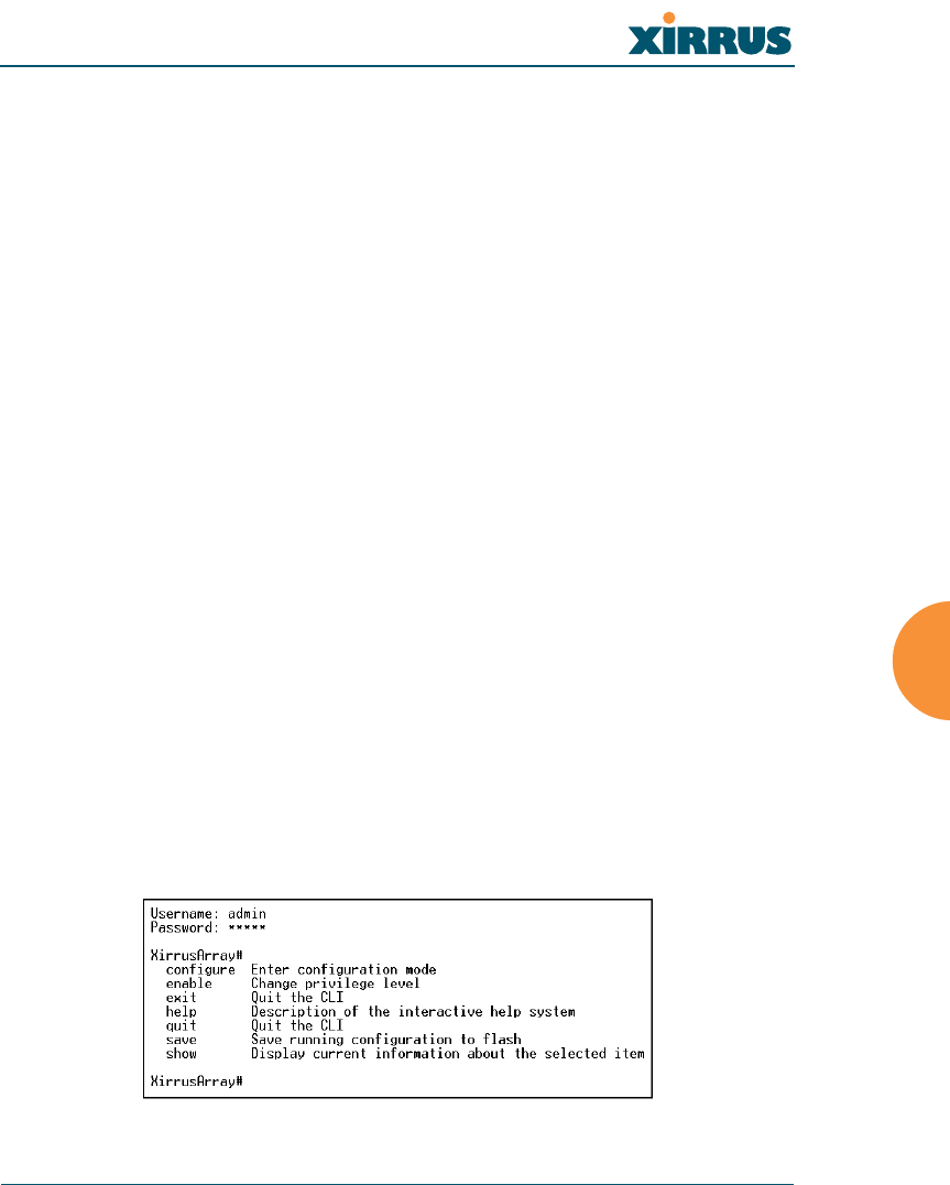
Wireless LAN Array
The Command Line Interface 117
The Command Line Interface
This chapter covers configuration and management tasks using the product’s
Command Line Interface (CLI), and includes a procedure for establishing a Telnet
connection to the XS-3900. Section headings for this chapter include:
zEstablishing a Secure Shell (SSH) Connection
zBasic Commands
zCommand Modes
zSelecting Interfaces
zCommand Line Keywords
zInterface Selection
Establishing a Secure Shell (SSH) Connection
Use this procedure to initialize the system and log in to the Command Line
Interface (CLI) via a Secure Shell (SSH) utility, such as PuTTY.
1. Start your SSH session and communicate with the XS-3900 via its default
IP address (10.0.1.1).
When connected to the XS-3900, a login prompt appears on your screen.
The default login user name and password is admin (for both). Login
names and passwords are case-sensitive.
2. Enter admin when prompted for a user name and password. You are
now logged in to the XS-3900’s Command Line Interface.
Figure 81. Command Line Interface

Wireless LAN Array
118 The Command Line Interface
Basic Commands
Help
To get help at any point type help or ?.
Tab Key
The Tab Key allows auto-completion of commands such that only a few unique
characters need to be entered followed by the Tab Key, which will automatically
fill in the rest of the command.
? Key
The ? key displays the list of available commands at any point of typing in the
command line.
Save
You must type save to save the current configuration to flash memory so that
changes are kept when the array is rebooted.
Command Modes
Configure Mode
Allows major functional changes to interfaces and configuration.
Requires Read/Write Administrator Privilege
Xirrus-Array# configure
Xirrus-Array(config)#
The prompt will change to show the current mode in parentheses.
SSID Mode
Allows configuration changes to SSID definitions.
Requires Read/Write Administrator Privilege
From configure mode type ssid <ENTER>
Xirrus-Array(config)# ssid
Xirrus-Array(config-SSID)#

Wireless LAN Array
The Command Line Interface 119
Radius Mode
Allows configuration changes to the internal RADIUS server.
Requires Read/Write Administrator Privilege
From configure mode type radius <ENTER>
Xirrus-Array(config)# radius
Xirrus-Array(config-radsrv)#
Run Test Mode
Allows configuration and execution of tests
Requires Read/Write Administrator Privilege
From configure mode type run-tests <ENTER>
Xirrus-Array(config)# run-tests
Xirrus-Array(Run Test)#
Selecting Interfaces
From the configure mode select the desired interface.
interface {console | iap | gig1 | gig2 | eth0};
console asyncronous serial console port
iap integrated access point interface
gig1 gigabit Ethernet interface
gig2 gigabit Ethernet interface
eth0 10/100 Ethernet interface
Example:
Xirrus-Array(config)# interface iap
Xirrus-Array(config-iap)#

Wireless LAN Array
120 The Command Line Interface
Command Line Keywords
This section provides a brief description of available keywords, including any
user-defined parameters associated with the keyword. An example of the
keyword’s usage is also provided. Keywords are grouped by function. If you
need to find a specific keyword, go to “Alphabetical Listing of CLI Keywords” on
page 173 and click on the keyword—you will be taken to the keyword definition
within this section. Functional groups in this section include:
zInterface Selection
zInterface Configuration
zRadio Configuration
zBeacon Information
zSystem Administration
zSystem Testing
zSecurity
zStation Timeouts
zSSID Configuration
zDNS Configuration
zNTP Configuration
zDHCP Configuration
zSyslog Configuration
zSNMP Configuration
zFilters
zRadius Configuration
zReports
zData Handling
zData Clearance
zShow Information
zRemove Configuration
zHelp

Wireless LAN Array
The Command Line Interface 121
Interface Selection
The following keywords are used when choosing an interface.
dot11a
dot11g
faste
gigabit
interface
line
Description: Select 802.11a WLAN interface
Usage: interface { dot11a }
Parameters: none
Description: Select 802.11g WLAN interface
Usage: interface { dot11g }
Parameters: none
Description: Select 10/100 Fast Ethernet interface
Usage: interface { faste }
Parameters: none
Description: Select 10/100/1000 Gigabit Ethernet interface
Usage: interface { gigabit }
Parameters: none
Description: Select the interface you want to configure
Usage: interface { line | dot11a | dot11g | gigabit | faste }
Parameters: none
Description: Select the asynchronous serial port
Usage: interface { line }
Parameters: none

Wireless LAN Array
122 The Command Line Interface
Interface Configuration
The following keywords are used for configuring the selected interface (assumes
the interface has already been selected).
autoduplex
baud
bytesize
def
Description: Select the duplex mode automatically
Usage: <genum> | <fenum> { autoduplex }
Parameters: <genum> defines the Gigabit interface, either 1 or 2, where:
1 = Primary, 2 = Secondary
<fenum> defines the Fast Ethernet interface (must be zero)
Description: Set the asynchronous port baud rate
Usage: <linenum> { baud <brate> }
Parameters: <linenum> defines which asynchronous interface is used
<brate> defines the range for the baud rate, between 2,400 and
19,200 bps
Description: Define the asynchronous port word size
Usage: <linenum> { bytesize <bsz> }
Parameters: <linenum> defines which asynchronous interface is used
<bsz> defines the byte/word size, either 7 or 8, where:
7 = 7 bits, 8 = 8 bits
Description: Reset the interface to the default values
Usage: <genum> | <fenum> { def }
Parameters: <genum> defines the Gigabit interface, either 1 or 2, where:
1 = Primary, 2 = Secondary
<fenum> defines the Fast Ethernet interface (must be zero)
<mtusz> defines the maximum allowable Maximum
Transmission Unit (MTU) , between 64 and 1794

Wireless LAN Array
The Command Line Interface 123
dhcpbind
down
fullduplex
gateway
Description: Obtain a DHCP address for this interface
Usage: <genum> | <fenum> { dhcpbind <dbind> }
Parameters: <genum> defines the Gigabit interface, either 1 or 2, where:
1 = Primary, 2 = Secondary
<fenum> defines the Fast Ethernet interface (must be zero)
<dbind> defines how the IP address is generated, either 0 or 1,
where:
0 = Use static IP address, 1 = Use DHCP to get IP address
Description: Shut down this interface
Usage: <genum> | <fenum> { down }
Parameters: <genum> defines the Gigabit interface, either 1 or 2, where:
1 = Primary, 2 = Secondary
<fenum> defines the Fast Ethernet interface (must be zero)
Description: Select the full duplex mode
Usage: <genum> | <fenum> { fullduplex }
Parameters: <genum> defines the Gigabit interface, either 1 or 2, where:
1 = Primary, 2 = Secondary
<fenum> defines the Fast Ethernet interface (must be zero)
Description: Define a gateway IP address
Usage: <genum> | <fenum> { gateway <gway> }
Parameters: <genum> defines the Gigabit interface, either 1 or 2, where:
1 = Primary, 2 = Secondary
<fenum> defines the Fast Ethernet interface (must be zero)
<gway> defines a valid gateway IP address

Wireless LAN Array
124 The Command Line Interface
halfduplex
ip-addr
management
mask
Description: Select the half duplex mode
Usage: <genum> | <fenum> { halfduplex }
Parameters: <genum> defines the Gigabit interface, either 1 or 2, where:
1 = Primary, 2 = Secondary
<fenum> defines the Fast Ethernet interface (must be 0)
Description: Define a static IP address
Usage: <genum> | <fenum> { ip-addr <statip> }
Parameters: <genum> defines the Gigabit interface, either 1 or 2, where:
1 = Primary, 2 = Secondary
<fenum> defines the Fast Ethernet interface (must be zero)
<statip> defines a valid static IP address
Description: Allow management on this interface
Usage: <genum> | <fenum> { management <mgmt> }
Parameters: <genum> defines the Gigabit interface, either 1 or 2, where:
1 = Primary, 2 = Secondary
<fenum> defines the Fast Ethernet interface (must be zero)
<mgmt> selects management or no management, where:
0 = No, 1 = Yes
Description: Define the subnet mask IP address
Usage: <genum> | <fenum> { mask <ipmask> }
Parameters: <genum> defines the Gigabit interface, either 1 or 2, where:
1 = Primary, 2 = Secondary
<fenum> defines the Fast Ethernet interface (must be zero)
<ipmask> defines a valid subnet mask IP address

Wireless LAN Array
The Command Line Interface 125
mtu
parity
speed
stopbits
Description: Set the maximum allowable MTU size
Usage: <genum> | <fenum> { mtu <mtusz> }
Parameters: <genum> defines the Gigabit interface, either 1 or 2, where:
1 = Primary, 2 = Secondary
<fenum> defines the Fast Ethernet interface (must be zero)
<mtusz> defines the maximum allowable MTU size, between
64 and 1794
Description: Establish the asynchronous port’s parity
Usage: <linenum> { parity <prty> }
Parameters: <linenum> defines which asynchronous interface is used
<prty> defines the parity, either 0, 1 or 2, where:
0 = No parity, 1 = Odd parity, 2 = Even parity
Description: Set the Ethernet interface speed
Usage: <genum> | <fenum> { speed <spdsel> }
Parameters: <genum> defines the Gigabit interface, either 1 or 2, where:
1 = Primary, 2 = Secondary
<fenum> defines the Fast Ethernet interface (must be zero)
<spdsel> defines the link speed, either 0 or 1, where:
0 = 100 Mbps, 1 = 1000 Mbps
Description: Set the asynchronous port’s number of stop bits
Usage: <linenum> { stopbits <sbit> }
Parameters: <linenum> defines which asynchronous interface is used
<sbit> defines the number of stop bits, either 0, 1 or 2

Wireless LAN Array
126 The Command Line Interface
up
Radio Configuration
The following keywords are used when configuring the XS-3900’s radios
(assumes the interface has already been selected).
antenna
antennaexternal
basic1
basic11
basic12
Description: Bring up this interface
Usage: <genum> | <fenum> { up }
Parameters: <genum> defines the Gigabit interface, either 1 or 2, where:
1 = Primary, 2 = Secondary
<fenum> defines the Fast Ethernet interface (must be zero)
Description: Set the direction for this radio antenna
Usage: <rnum> { antenna }
Parameters: <rnum> defines the radio number, between 1 and 16
Description: Show the external antenna settings
Usage: <rnum> { antennaexternal }
Parameters: <rnum> defines the radio number, between 1 and 16
Description: Require 1 Mbps rate
Usage: <rnum> { basic1 }
Parameters: <rnum> defines the radio number, between 13 and 16
Description: Require 11 Mbps rate
Usage: <rnum> { basic11 }
Parameters: <rnum> defines the radio number, between 13 and 16
Description: Require 12 Mbps rate
Usage: <rnum> { basic12 }
Parameters: <rnum> defines the radio number, between 1 and 16

Wireless LAN Array
The Command Line Interface 127
basic18
basic2
basic24
basic36
basic48
basic5
basic54
Description: Require 18 Mbps rate
Usage: <rnum> { basic18 }
Parameters: <rnum> defines the radio number, between 1 and 16
Description: Require 2 Mbps rate
Usage: <rnum> { basic2 }
Parameters: <rnum> defines the radio number, between 13 and 16
Description: Require 24 Mbps rate
Usage: <rnum> { basic24 }
Parameters: <rnum> defines the radio number, between 1 and 16
Description: Require 36 Mbps rate
Usage: <rnum> { basic36 }
Parameters: <rnum> defines the radio number, between 1 and 16
Description: Require 48 Mbps rate
Usage: <rnum> { basic48 }
Parameters: <rnum> defines the radio number, between 1 and 16
Description: Require 5 Mbps rate
Usage: <rnum> { basic5 }
Parameters: <rnum> defines the radio number, between 13 and 16
Description: Require 54 Mbps rate
Usage: <rnum> { basic54 }
Parameters: <rnum> defines the radio number, between 1 and 16

Wireless LAN Array
128 The Command Line Interface
basic6
basic9
cca
cell-size
channelnum
configure
Description: Require 6 Mbps rate
Usage: <rnum> { basic6 }
Parameters: <rnum> defines the radio number, between 1 and 16
Description: Require 9 Mbps rate
Usage: <rnum> { basic9 }
Parameters: <rnum> defines the radio number, between 1 and 16
Description: Employ Clear Channel Assessment function
Usage: <rnum> { cca <ccadb> }
Parameters: <rnum> defines the radio number, between 1 and 16
<ccadb> is a number between 0 and 60 to define the floor noise
level in dB increments
Description: Define cell size
Usage: <rnum> { cell-size <cszset> }
Parameters: <rnum> defines the radio number, between 1 and 16
<cszset> is defined as either 0, 1 or 2, where:
0 = smallest, 1 = medium, 2 = largest
Description: Define static channel setting
Usage: <rnum> { channelnum <cnum> }
Parameters: <rnum> defines the radio number, between 1 and 16
<cnum> defines the static channel number
Description: Configure each radio individually
Usage: <rnum> { configure }
Parameters: <rnum> defines the radio number, between 1 and 16

Wireless LAN Array
The Command Line Interface 129
default_rates
description
dot11gonly
dot11preamble
down
edcf
enable1
Description: Set default rates
Usage: <rnum> { default_rates }
Parameters: <rnum> defines the radio number, between 1 and 16
Description: Specify a name to identify this interface
Usage: <rnum> { description <dot11desc> }
Parameters: <rnum> defines the radio number, between 1 and 16
<dot11desc> is defined as a string of up to 50 alphanumeric
characters
Description: Enable support for 802.11g only
Usage: <rnum> { dot11gonly }
Parameters: <rnum> defines the radio number, between 1 and 16
Description: Define the preamble
Usage: <rnum> { dot11preamble }
Parameters: <rnum> defines the radio number, between 1 and 16
Description: Shut down (disable) this radio interface
Usage: <rnum> { down }
Parameters: <rnum> defines the radio number, between 1 and 16
Description: Enable EDCF support
Usage: <rnum> { edcf }
Parameters: <rnum> defines the radio number, between 1 and 16
Description: Allow 1 Mbps rate
Usage: <rnum> { enable1 }
Parameters: <rnum> defines the radio number, between 13 and 16

Wireless LAN Array
130 The Command Line Interface
enable11
enable12
enable18
enable2
enable24
enable36
enable48
Description: Allow 11 Mbps rate
Usage: <rnum> { enable11 }
Parameters: <rnum> defines the radio number, between 13 and 16
Description: Allow 12 Mbps rate
Usage: <rnum> { enable12 }
Parameters: <rnum> defines the radio number, between 1 and 16
Description: Allow 18 Mbps rate
Usage: <rnum> { enable18 }
Parameters: <rnum> defines the radio number, between 1 and 16
Description: Allow 2 Mbps rate
Usage: <rnum> { enable2 }
Parameters: <rnum> defines the radio number, between 13 and 16
Description: Allow 24 Mbps rate
Usage: <rnum> { enable24 }
Parameters: <rnum> defines the radio number, between 1 and 16
Description: Allow 36 Mbps rate
Usage: <rnum> { enable36 }
Parameters: <rnum> defines the radio number, between 1 and 16
Description: Allow 48 Mbps rate
Usage: <rnum> { enable48 }
Parameters: <rnum> defines the radio number, between 1 and 16

Wireless LAN Array
The Command Line Interface 131
enable5
enable54
enable6
enable9
frag-threshold
least_congested
long-retry-limit
Description: Allow 5 Mbps rate
Usage: <rnum> { enable5 }
Parameters: <rnum> defines the radio number, between 13 and 16
Description: Allow 54 Mbps rate
Usage: <rnum> { enable54 }
Parameters: <rnum> defines the radio number, between 1 and 16
Description: Allow 6 Mbps rate
Usage: <rnum> { enable6 }
Parameters: <rnum> defines the radio number, between 1 and 16
Description: Allow 9 Mbps rate
Usage: <rnum> { enable9 }
Parameters: <rnum> defines the radio number, between 1 and 16
Description: Define the fragmentation threshold
Usage: <rnum> { frag-threshold <fragt> }
Parameters: <rnum> defines the radio number, between 1 and 16
<fragt> defines the fragment size
Description: Scan for the best frequency
Usage: <rnum> { least_congested }
Parameters: <rnum> defines the radio number, between 1 and 16
Description: Specify the long retry limit
Usage: <rnum> { long-retry-limit <lrl> }
Parameters: <rnum> defines the radio number, between 1 and 16
<lrl> defines the long retry limit

Wireless LAN Array
132 The Command Line Interface
max-client-txpwr
off
on
prelong
preshort
range
rate1
Description: Limit the client’s maximum transmit power
Usage: <rnum> { max-client-txpwr <mcp> }
Parameters: <rnum> defines the radio number, between 1 and 16
<mcp> specifies a number (in milliwatts)
Description: Turn OFF this feature
Usage: <rnum> { off }
Parameters: <rnum> defines the radio number, between 1 and 16
Description: Turn ON this feature
Usage: <rnum> { on }
Parameters: <rnum> defines the radio number, between 1 and 16
Description: Enable long preamble for the selected radio
Usage: <rnum> { prelong }
Parameters: <rnum> defines the radio number, between 1 and 16
Description: Enable short preamble for the selected radio
Usage: <rnum> { preshort }
Parameters: <rnum> defines the radio number, between 1 and 16
Description: Set rates for best range
Usage: <rnum> { range }
Parameters: <rnum> defines the radio number, between 1 and 16
Description: Configure the 1 Mbps rate
Usage: <rnum> { rate1 }
Parameters: <rnum> defines the radio number, between 13 and 16

Wireless LAN Array
The Command Line Interface 133
rate11
rate12
rate18
rate2
rate24
rate36
rate48
Description: Configure the 11 Mbps rate
Usage: <rnum> { rate11 }
Parameters: <rnum> defines the radio number, between 13 and 16
Description: Configure the 12 Mbps rate
Usage: <rnum> { rate12 }
Parameters: <rnum> defines the radio number, between 1 and 16
Description: Configure the 18 Mbps rate
Usage: <rnum> { rate18 }
Parameters: <rnum> defines the radio number, between 1 and 16
Description: Configure the 2 Mbps rate
Usage: <rnum> { rate2 }
Parameters: <rnum> defines the radio number, between 13 and 16
Description: Configure the 24 Mbps rate
Usage: <rnum> { rate24 }
Parameters: <rnum> defines the radio number, between 1 and 16
Description: Configure the 36 Mbps rate
Usage: <rnum> { rate36 }
Parameters: <rnum> defines the radio number, between 1 and 16
Description: Configure the 48 Mbps rate
Usage: <rnum> { rate48 }
Parameters: <rnum> defines the radio number, between 1 and 16

Wireless LAN Array
134 The Command Line Interface
rate5
rate54
rate6
rate9
receiving
rts-threshold
Rxdiversity
Description: Configure the 5 Mbps rate
Usage: <rnum> { rate5 }
Parameters: <rnum> defines the radio number, between 13 and 16
Description: Configure the 54 Mbps rate
Usage: <rnum> { rate54 }
Parameters: <rnum> defines the radio number, between 1 and 16
Description: Configure the 6 Mbps rate
Usage: <rnum> { rate6 }
Parameters: <rnum> defines the radio number, between 1 and 16
Description: Configure the 9 Mbps rate
Usage: <rnum> { rate9 }
Parameters: <rnum> defines the radio number, between 1 and 16
Description: Configure the input antenna
Usage: <rnum> { receiving }
Parameters: <rnum> defines the radio number, between 1 and 16
Description: Define the RTS threshold
Usage: <rnum> { rts-threshold <rtst> }
Parameters: <rnum> defines the radio number, between 1 and 16
<rtst> defines the packet size at which the device issues a
Request to Send (RTS) before sending the packet
Description: Choose the antenna with the best signal
Usage: <rnum> { Rxdiversity }
Parameters: <rnum> defines the radio number, between 1 and 16

Wireless LAN Array
The Command Line Interface 135
Rxleft
Rxright
short-retry-limit
speed
throughput
transmiting
Txdiversity
Description: Specify the left antenna
Usage: <rnum> { Rxleft }
Parameters: <rnum> defines the radio number, between 1 and 16
Description: Specify the right antenna
Usage: <rnum> { Rxright }
Parameters: <rnum> defines the radio number, between 1 and 16
Description: Define t short retry limit
Usage: <rnum> { short-retry-limit <srl> }
Parameters: <rnum> defines the radio number, between 1 and 16
<srl> defines the short retry limit
Description: Set allowed radio bit rates
Usage: <rnum> { speed }
Parameters: <rnum> defines the radio number, between 1 and 16
Description: Set rates for best throughput
Usage: <rnum> { throughput }
Parameters: <rnum> defines the radio number, between 1 and 16
Description: Configure the output antenna
Usage: <rnum> { transmiting }
Parameters: <rnum> defines the radio number, between 1 and 16
Description: Choose the antenna with the best signal
Usage: <rnum> { Txdiversity }
Parameters: <rnum> defines the radio number, between 1 and 16

Wireless LAN Array
136 The Command Line Interface
Txleft
tx-pwr
Txright
up
worldbeacon
Beacon Information
The following keywords are used when establishing beacon information.
beacon
Description: Specify the left antenna
Usage: <rnum> { Txleft }
Parameters: <rnum> defines the radio number, between 1 and 16
Description: Define the transmit power settings
Usage: <rnum> { tx-pwr <pwrset> }
Parameters: <rnum> defines the radio number, between 1 and 16
<pwrset> is defined as either 0, 1 or 2, where:
0 = quarter, 1 = half, 2 = maximum
Description: Specify the right antenna
Usage: <rnum> { Txright }
Parameters: <rnum> defines the radio number, between 1 and 16
Description: Bring up (enable) this radio interface
Usage: <rnum> { up }
Parameters: <rnum> defines the radio number, between 1 and 16
Description: Enable support for world mode beacons
Usage: <rnum> { worldbeacon }
Parameters: <rnum> defines the radio number, between 1 and 16
Description: Establish beacon information
Usage: beacon { period | DTIM-rate }
Parameters: none

Wireless LAN Array
The Command Line Interface 137
DTIM-rate
period
System Administration
The following keywords are used for system administration tasks.
administrator
clock-set
contact-info
Description: Determine beacon periods before the Delivery Traffic
Indication Message (DTIM) is sent
Usage: beacon { DTIM-rate <beaconr> }
Parameters: <beaconr> defines the period between DTIM frames, in Kusecs
(kilo microseconds), where 1 Kusec = 1024 microseconds
Description: Establish the amount of time between beacons
Usage: beacon { period <beaconp> }
Parameters: <beaconp> defines the period between beacons, in Kusecs (kilo
microseconds), where 1 Kusec = 1024 microseconds
Description: Define the administrator access parameters
Usage: administrator { defpw | userid <uid> }
Parameters: <uid> enter a unique user ID
Description: Set the date/time within the XS-3900
Usage: clock-set <curdate>
Parameters: <curdate> defines the current date and time, specified in the
following format: MMDDhhmmYYYY
Description: Define the contact information for assistance on this XS-3900
Usage: contact-info { name <conname> | email <emailcontact>|
telephone <contele> }
Parameters: <conname> defines the contact name, up to 50 characters
<emailcontact> defines the email address of the contact, up to
50 characters
<contele> defines the telephone number of the contact

Wireless LAN Array
138 The Command Line Interface
copy
default-gateway
defpw
dhcp-server
dir
domain-name
Description: Copy a file to another file
Usage: copy <fromfile> <tofile>
Parameters: <fromfile> specifies the originating file
<tofile> specifies the destination file
Description: Define the default gateway IP address
Usage: ip { default-gateway <defgtwy> }
Parameters: <defgtwy> specifies the default gateway IP address
Description: Define the default password, up to 50 characters
Usage: administrator { defpw }
Parameters: none
Description: Define the DHCP server IP address
Usage: ip { dhcp-server <dhcpservr> }
Parameters: <dhcpservr> specifies the DHCP server IP address
Description: List the directory contents
Usage: dir
Parameters: none
Description: Define the domain site name
Usage: ip { domain-name <domainnm>}
Parameters: <domainnm> specifies the domain name for unqualified hosts

Wireless LAN Array
The Command Line Interface 139
email
erase
ftp
hostname
ip
location
Description: Define an email address for assistance on this XS-3900
Usage: contact-info { email <emailcontact> }
Parameters: <emailcontact> defines the email address of the contact, up to
50 characters
Description: Delete a file from the flash file system
Usage: erase <erasefile>
Parameters: <erasefile> specifies the target file to erase
Description: Open an FTP connection with a remote server
Usage: ftp <addr>
Parameters: <addr> specifies the host name or IP address of the FTP server
Description: Define a hostname for this XS-3900
Usage: hostname <hname>
Parameters: <hname> defines the host name given to this XS-3900
Description: Define the IP command set
Usage: ip { default-gateway <defgtwy> | dhcp-server <dhcpservr> |
name-server <nameservr> | domain-name <domainnm>}
Parameters: <defgtwy> specifies the default gateway IP address
<dhcpservr> specifies the DHCP server IP address
<nameservr> specifies the DNS host name
<domainnm> specifies the domain name for unqualified hosts
Description: Define the location for this XS-3900
Usage: location <locname>
Parameters: <locname> defines the location assigned to this XS-3900

Wireless LAN Array
140 The Command Line Interface
logout
model
more
name
name-server
radios
reboot
Description: Log out the current administrator
Usage: logout
Parameters: none
Description: Get model number
Usage: show-version { model }
Parameters: none
Description: Get more (list file)
Usage: more <morefile>
Parameters: <morefile> specifies the target file to list
Description: Define a contact name for assistance on this XS-3900
Usage: contact-info { name <conname> }
Parameters: <conname> defines the contact name, up to 50 characters
Description: Define the DNS host name
Usage: ip { name-server <nameservr> }
Parameters: <nameservr> specifies the DNS host name
Description: Get radio board version numbers
Usage: show-version { radios }
Parameters: none
Description: Reboot the XS-3900
Usage: reboot
Parameters: none

Wireless LAN Array
The Command Line Interface 141
reload
reset
serial
show-version
shut-down
software
userid
Description: Reload and reset the XS-3900
Usage: reload
Parameters: none
Description: Reset the XS-3900 to its factory defaults
Usage: reset
Parameters: none
Description: Get serial number
Usage: show-version { serial }
Parameters: none
Description: Get system version information
Usage: show-version { model | serial | software | radios }
Parameters: none
Description: Shut down the entire system
Usage: shut-down
Parameters: none
Description: Get software version
Usage: show-version { software }
Parameters: none
Description: Define individual user IDs
Usage: administrator { userid <uid> }
Parameters: <uid> enter a unique user ID

Wireless LAN Array
142 The Command Line Interface
System Testing
The following keywords are used for system testing.
led
linktest
ping
run-tests
Description: Run LED tests
Usage: run-tests { led <ledtst> }
Parameters: <ledtst> specifies the LED to test (defined by LED number, 0 to
9—refer to “Now that the XS-3900 is physically installed, you
must run the Express Setup procedure from the unit’s Web
Management Interface to enable the radios and establish initial
system configuration settings. Go to “Powering Up the XS-
3900” on page 44.” on page 43)
Description: Run link tests
Usage: run-tests { linktest <ltest> }
Parameters: <linktest> specifies the link test, 1 through 4, where:
1 = tbd, 2 = tbd, 3 = tbd, 4 = tbd
Description: Execute the ping utility
Usage: run-tests { ping <pingname> }
Parameters: <pingname> specifies target IP address or DNS name to ping
Description: Run a selected test
Usage: run-tests { traceroute <tracename> | ping <pingname> | led
<ledtst> | linktest <ltest> }

Wireless LAN Array
The Command Line Interface 143
traceroute
Security
The following keywords are used for system security.
all11a
all11g
allradios
broadcastkey
Parameters: <tracename> specifies target IP address or DNS name to trace
<pingname> specifies target IP address or DNS name to ping
<ledtst> specifies the LED to test (defined by LED number, 0 to
9—refer to “Now that the XS-3900 is physically installed, you
must run the Express Setup procedure from the unit’s Web
Management Interface to enable the radios and establish initial
system configuration settings. Go to “Powering Up the XS-
3900” on page 44.” on page 43)
<linktest> specifies the link test, 1 through 4, where:
1 = tbd, 2 = tbd, 3 = tbd, 4 = tbd
Description: Run a trace on an IP route or DNS name
Usage: run-tests { traceroute <tracename> }
Parameters: <tracename> specifies target IP address or DNS name to trace
Description: Specify that any settings will apply to all 802.11a radios
Usage: security { radioid { all11a }}
Parameters: none
Description: Specify that any settings will apply to all 802.11g radios
Usage: security { radioid { all11g }}
Parameters: none
Description: Specify that any settings will apply to all radios
Usage: security { radioid { allradios }}
Parameters: none
Description: Use the encryption key during broadcast

Wireless LAN Array
144 The Command Line Interface
capabilitychange
change
ciphers
client-timeout
dot1x
encryption
Usage: security { radioid { all11g { broadcastkey }}}
Parameters: none
Description: Issue a new key if the previous non-key STA disassociates, or
the first non-key STA associates (optional)
Usage: security { radioid { all11g { capabilitychange }}}
Parameters: none
Description: Specify the time between key rotations (optional)
Usage: security { radioid { all11g { change <chgsecs> }}}
Parameters: <chgsecs> sets the time (in seconds) between key rotations
Description: Enable a cipher suite for encryption
Usage: security { radioid { allradios { encryption { ciphers { tkip {
tkipwep40 }}}}}}
Parameters: none
Description: Define a timeout period while waiting for a client station
Usage: security { radioid { all11g { client-timeout <ct01x> }}}
Parameters: <ct01x> sets the client time out, in seconds from 1 to 65555
Description: Specify the 802.1x STA timeout parameters
Usage: security { radioid { all11g { dot1x }}}
Parameters: none
Description: Define which WEP key will be used for data encryption
Usage: security { radioid { allradios { encryption <keynum> }}}
Parameters: <keynum> specifies the encryption key number, 1 to 4

Wireless LAN Array
The Command Line Interface 145
keyhash
mandatory
Description: Use encryption key hashing
Usage: security { radioid { allradios { encryption { ciphers { tkip {
tkipwep40 { keyhash }}}}}}}
Parameters: none
Description: Force station to use encryption to communicate with the XS-
3900
Usage: security { radioid { allradios { encryption { mandatory }}}}
Parameters: none

Wireless LAN Array
146 The Command Line Interface
membershiptermination
mic
optional
optkeyhash
radioid
reauth-period
Description: Specify the time between key rotations (optional)
Usage: security { radioid { all11g { membershiptermination }}}
Parameters: none
Description: Use the Message Integrity Check (MIC) function
Usage: security { radioid { allradios { encryption { ciphers { tkip {
tkipwep40 { mic }}}}}}}
Parameters: none
Description: Allow station to communicate with the XS-3900 with or
without encryption
Usage: security { radioid { allradios { encryption { optional }}}}
Parameters: none
Description: Use encryption key hashing (optional)
Usage: security { radioid { allradios { encryption { optional {
optkeyhash }}}}}
Parameters: none
Description: Choose which radio (or all radios)
Usage: security { radioid { allradios | all11a | all11g | <radionum> }}}
Parameters: <radionum> specifies the radio number (1 to 16)
Description: Define the reauthentication period, in seconds
Usage: security { radioid { all11g { reauth-period <reauthper> }}}
Parameters: <reauthper> specifies the time before the next authentication
attempt, between 1 and 65555 seconds

Wireless LAN Array
The Command Line Interface 147
security
server
tkip
tkipwep128
tkipwep40
wep
Description: Set the security parameters for the XS-3900’s radios
Usage: security { radioid { allradios { encryption <keynum> }}}
Parameters: <keynum> specifies the encryption key number, 1 to 4
Description: Use the RADIUS server's reauthentication value instead of
“reauth-period” value
Usage: security { radioid { all11g { server }}}
Parameters: none
Description: Specify TKIP as the cipher suite
Usage: security { radioid { allradios { encryption { ciphers { tkip {
tkipwep40 }}}}}}
Parameters: none
Description: Use 128 bit WEP with the TKIP cipher suite
Usage: security { radioid { allradios { encryption { ciphers { tkip {
tkipwep128 }}}}}}
Parameters: none
Description: Use 40 bit WEP with the TKIP cipher suite
Usage: security { radioid { allradios { encryption { ciphers { tkip {
tkipwep40 }}}}}}
Parameters: none
Description: Select the encryption type when configured for WEP
Usage: security { radioid { allradios { encryption { wep }}}}
Parameters: none

Wireless LAN Array
148 The Command Line Interface
wep128
wep40
Station Timeouts
The following keywords are used for establishing STA timeouts.
activity-timeout
reauth-period
sta-timeouts
Description: Use 128 bit WEP encryption
Usage: security { radioid { allradios { encryption { wep128 }}}}
Parameters: none
Description: Use 40 bit WEP encryption
Usage: security { radioid { allradios { encryption { wep40 }}}}
Parameters: none
Description: Set the time period before the XS-3900 flags an inactive station
Usage: sta-timeouts { activity-timeout <at> }
Parameters: <at> specifies the time, in seconds, before the system flags an
inactive STA
Description: Set the period after a station fails to authenticate before
allowing more attempts
Usage: sta-timeouts { reauth-period <ht> }
Parameters: <ht> specifies the time, in seconds, before the next
authentication attempt
Description: Set the station timeouts
Usage: sta-timeouts { activity-timeout <at> | reauth-period <ht> }
Parameters: <at> specifies the time, in seconds, before the system flags an
inactive STA
<ht> specifies the time, in seconds, before the next
authentication attempt

Wireless LAN Array
The Command Line Interface 149
SSID Configuration
The following keywords are used for establishing SSID parameters.
add
del
policy
qos-ssid
ssid
Description: Add this SSID
Usage: ssid-manager { ssid <ss> { add }}
Parameters: <ss> specifies the SSID, up to 32 characters
Description: Delete this SSID
Usage: ssid-manager { ssid <ss> { del }}
Parameters: <ss> specifies the SSID, up to 32 characters
Description: Define the policy associated with this SSID
Usage: ssid-manager { ssid <ss> { policy <sp> }}
Parameters: <ss> specifies the SSID, up to 32 characters
<sp>specifies the policy for this SSID, either 0, 1, 2 or 3, where:
0 = Open, 1 = MAC Auth., 2 = EAP Auth., 3 = Guest
Description: Define QoS associated with this SSID
Usage: ssid-manager { ssid <ss> { qos-ssid <qs> }}
Parameters: <ss> specifies the SSID, up to 32 characters
<qs> identifies the QoS for this SSID
Description: Define this SSID
Usage: ssid-manager { ssid <ss> { add }
Parameters: <ss> specifies the SSID, up to 32 characters

Wireless LAN Array
150 The Command Line Interface
ssid-brdcst
ssid-manager
vlan
DNS Configuration
The following keywords are used for establishing the DNS parameters.
dns
domain
Description: Specify if you want to broadcast this SSID
Usage: ssid-manager { ssid <ss> { ssid-brdcst <sb> }}
Parameters: <ss> specifies the SSID, up to 32 characters
<sb> specifies if you want to broadcast this SSID, either 0 or 1,
where:
0 = No, 1 = Yes
Description: Set up SSID for a specific radio or the complete system
Usage: ssid-manager { ssid <ss> { add }
Parameters: <ss> specifies the SSID, up to 32 characters
Description: Define a VLAN ID associated with this SSID
Usage: ssid-manager { ssid <ss> { vlan <sv> }}
Parameters: <sv> identifies the VLAN for this SSID
Description: Configure DNS settings
Usage: dns { hostname <hname> }
Parameters: <hname> specifies the host name
Description: Enter your domain name
Usage: dns { domain <dom> }
Parameters: <dom> specifies your domain name, for example:
www.mydomain.com

Wireless LAN Array
The Command Line Interface 151
hostname
server1
server2
server3
NTP Configuration
The following keywords are used for establishing the NTP parameters.
disable
enable
Description: Enter your host name
Usage: dns { hostname <hname> }
Parameters: <hname> specifies the host name
Description: Enter the primary DNS server
Usage: dns { server1 <srv1> }
Parameters: <srv1> specifies the primary DNS server
Description: Enter the primary DNS server
Usage: dns { server2 <srv2> }
Parameters: <srv2> specifies the secondary DNS server
Description: Enter the tertiary DNS server
Usage: dns { server3 <srv3> }
Parameters: <srv3> specifies the tertiary DNS server
Description: Disable NTP services
Usage: ntp { disable }
Parameters: none
Description: Enable NTP services
Usage: ntp { enable }
Parameters: none

Wireless LAN Array
152 The Command Line Interface
ntp
pri-nts
sec-nts
DHCP Configuration
The following keywords are used for establishing the DHCP parameters.
configure
default-lease
dhcp
Description: Enable/disable or configure NTP services
Usage: ntp { enable | disable }
Parameters: none
Description: Establish the primary NTP server IP address or DNS name
Usage: ntp { pri-nts <pntp> }
Parameters: <pntp> specifies the IP address or DNS name (primary)
Description: Establish the secondary NTP server IP address or DNS name
Usage: ntp { sec-nts <sntp> }
Parameters: <sntp> specifies the IP address or DNS name (secondary)
Description: Configure DHCP services
Usage: dhcp { configure { start-ip-range <sipr> }}
Parameters: <sipr> specifies the starting IP address
Description: Define the default lease period
Usage: dhcp { configure { default-lease <defl> }}
Parameters: <defl> specifies the default lease period, in minutes
Description: Enable/disable or configure DHCP services
Usage: dhcp { enable | disable | configure { start-ip-range <sipr> }}
Parameters: <sipr> specifies the starting IP address

Wireless LAN Array
The Command Line Interface 153
disable
enable
end-ip-range
max-lease
start-ip-range
Syslog Configuration
The following keywords are used for establishing the Syslog parameters.
buffered
Description: Disable DHCP services
Usage: dhcp { disable }
Parameters: none
Description: Enable DHCP services
Usage: dhcp { enable }
Parameters: none
Description: Define the DHCP server’s ending IP address
Usage: dhcp { configure { end-ip-range <eipr> }}
Parameters: <eipr> specifies the ending IP address
Description: Define the maximum allowable lease period
Usage: dhcp { configure { max-lease <maxl> }}
Parameters: <maxl> specifies the maximum allowable lease period, in
minutes
Description: Define the DHCP server’s starting IP address
Usage: dhcp { configure { start-ip-range <sipr> }}
Parameters: <sipr> specifies the starting IP address
Description: Set the size of the local Syslog file
Usage: syslog { buffered <logfilesz> }
Parameters: <logfilesz> sets the number of records the local Syslog file
holds before wrapping around

Wireless LAN Array
154 The Command Line Interface
configure
console
ipsyslog
level
on
syslog
Description: Configure Syslog services
Usage: syslog { configure { ipsyslog <slip> }}
Parameters: <slip> specifies the Syslog server IP address
Description: Display syslog messages on your console
Usage: syslog { configure { ipsyslog <slip> }}
Parameters: <slip> specifies the Syslog server IP address
Description: Define the Syslog server IP address
Usage: syslog { console }
Parameters: none
Description: Log all messages with the level you define here
Usage: syslog { level <slev> }
Parameters: <slev> defines the syslog capture level
Description: Turn on Syslog services
Usage: syslog { on }
Parameters: none
Description: Turn on/off or configure Syslog services
Usage: syslog { on | configure { ipsyslog <slip> }}
Parameters: <slip> specifies the Syslog server IP address

Wireless LAN Array
The Command Line Interface 155
SNMP Configuration
The following keywords are used for establishing the SNMP parameters.
community
disable
enable
snmp
snmpta
snmptp
Description: Define the SNMP communnity
Usage: snmp { community <csnmp> }
Parameters: <csnmp> specifies the SNMP Community string (letters and
number only, no spaces or special characters)
Description: Disable SNMP services
Usage: snmp { disable }
Parameters: none
Description: Enable SNMP services
Usage: snmp { enable }
Parameters: none
Description: Enable/disable or configure SNMP services
Usage: snmp { enable | disable | snmpti <tisnmp> }
Parameters: <tisnmp> specifies the SNMP trap IP address
Description: Send traps for authorization failures
Usage: snmp { snmpta <tasnmp> }
Parameters: <tasnmp> specifies whether or not to send traps, either 1 or 2,
where:
1 = Send, 2= Don’t send
Description: Define the SNMP trap port
Usage: snmp { snmptp <tpsnmp> }
Parameters: <tpsnmp> specifies the SNMP trap port

Wireless LAN Array
156 The Command Line Interface
snmpti
Filters
The following keywords are used for setting up filters.
configure
disable
enable
filters
Description: Define the SNMP trap IP address
Usage: snmp { snmpti <tisnmp> }
Parameters: <tisnmp> specifies the SNMP trap IP address
Description: Configure filters
Usage: filters { configure }
Parameters: none
Description: Disable filters
Usage: filters { disable }
Parameters: none
Description: Enable filters
Usage: filters { enable }
Parameters: none
Description: Enable/disable or configure filters
Usage: filters { enable | disable | configure }
Parameters: none

Wireless LAN Array
The Command Line Interface 157
Radius Configuration
The following keywords are used for configuring Radius services.
client-timeout
configure
dot1x
radius
radius-ip
radius-port
Description: Define 802.1x reply time from a client station
Usage: radius { radius-server { dot1x { client-timeout <cto1x> }}}
Parameters: <cto1x> specifies the time (in seconds) waiting for a client
station 802.1x reply before timing out
Description: Configure Radius server parameters
Usage: radius { radius-server { configure { radius-ip <radip> }}}
Parameters: <radip> specifies the IP address of the Radius server
Description: Define 802.1x client (STA) settings
Usage: radius { radius-server { configure { dot1x }}}
Parameters: none
Description: Configure Radius services
Usage: radius { radius-server { configure { radius-ip <radip> }}}
Parameters: <radip> specifies the IP address of the Radius server
Description: Define the Radius server IP address
Usage: radius { radius-server { configure { radius-ip <radip> }}}
Parameters: <radip> specifies the IP address of the Radius server
Description: Define the Radius authentication port
Usage: radius { radius-server { configure { radius-port <radport> }}}
Parameters: <radport> specifies the Radius authentication port

Wireless LAN Array
158 The Command Line Interface
radius-secret
radius-server
reauth-period
server
Reports
The following keywords are used for generating reports.
assoc
clear
Description: Define the Radius shared secret
Usage: radius { radius-server { configure { radius-secret <radsecret> }}}
Parameters: <radsecret> specifies the Radius shared secret
Description: Configure the Radius server
Usage: radius { radius-server { configure { radius-ip <radip> }}}
Parameters: <radip> specifies the IP address of the Radius server
Description: Specify the elapsed time before allowing a client station to
reattempt authentication
Usage: radius { radius-server { dot1x { reauth-period <reauthper> }}}
Parameters: <reauthper> specifies the amount of time (in seconds) after a
timeout you wait before allowing a client station to retry
authentication
Description: Use the “reauth-period” configured in the RADIUS server
Usage: radius { radius-server { dot1x { server }}}
Parameters: none
Description: Discover the number of devices associated with this XS-3900
Usage: reports { assoc }
Parameters: none
Description: Clear all stored values for the selected interface
Usage: reports { clear { GigE <gnum> }}
Parameters: <gnum> defines the gigabit interface number, either 0 or 1

Wireless LAN Array
The Command Line Interface 159
configure
disable
Dot11
enable
GigE
num-ap
num-Client
Description: Configure and request reports for the selected interface
Usage: reports { configure { Dot11 <rnum> }}
Parameters: <rnum> defines the radio number, between 1 and 16
Description: Disable report generation
Usage: reports { disable }
Parameters: none
Description: Generate reports for the selected radio
Usage: reports { configure { Dot11 <rnum> }}
Parameters: <rnum> defines the radio number, between 1 and 16
Description: Enable report generation
Usage: reports { enable }
Parameters: none
Description: Generate reports for the selected gigabit interface
Usage: reports { configure { GigE <gnum> }}
Parameters: <gnum> defines the gigabit interface number, either 0 or 1
Description: Discover the number of AP devices associated with this XS-
3900
Usage: reports { num-ap }
Parameters: none
Description: Discover the number of clients associated with this XS-3900
Usage: reports { num-Client }
Parameters: none

Wireless LAN Array
160 The Command Line Interface
reports
Data Handling
The following keywords are used for defining how data is handled by the system.
packet
payload-encapsulation
retries
Data Clearance
The following keywords are used for clearing or removing data from selected
elements.
clear
Description: Enable/disable or configure report generation
Usage: reports { enable | disable | configure | clear }}}
Parameters: none
Description: Define global packet commands
Usage: packet { retries <pktretry> | payload-encapsulation <encap1> }
Parameters: <pktretry> specifies the packet retry value
<encap1> choose either dot1H or snap
Description: Define the type of encapsulation to use
Usage: packet { payload-encapsulation <encap1> }
Parameters: <encap1> choose either dot1H or snap
Description: Define the maximum number of retries for sending a packet
Usage: packet { retries <pktretry> }
Parameters: <pktretry> specifies the packet retry value
Description: Remove/clear requested elements
Usage: clear { dot11 { client <stamacaddr> }}
Parameters: <stamacaddr> specifies the MAC address of a client station
you want to disassociate

Wireless LAN Array
The Command Line Interface 161
client
dot11
statistics
Show Information
The following keywords are used for displaying system information.
adjacent-ap
carrier-busy
Description: Designates a client station to deauthenticate
Usage: clear { dot11 { client <stamacaddr> }}
Parameters: <stamacaddr> specifies the MAC address of a client station
you want to disassociate
Description: Designates a wireless interface
Usage: clear { dot11 { client <stamacaddr> }}
Parameters: <stamacaddr> specifies the MAC address of a client station
you want to disassociate
Description: Designates accumulated counters, such as amount of data
transmissions
Usage: clear { dot11 { statistics <statmac> }}
Parameters: <statmac> specifies the MAC address of a client station from
which you want clear all statistical data
Description: Select all adjacent APs that are members of a WDS roaming
neighborhood
Usage: show { dot11 { adjacent-ap }}
Parameters: none
Description: Show the percentage of CCA that is busy
Usage: show { carrier-busy }
Parameters: none

Wireless LAN Array
162 The Command Line Interface
controllers
dot11
dot11radio
file
flash
hosts
info
Description: Display radio baseband information
Usage: show { controllers { dot11radio <contnum> }}
Parameters: <contnum> specifies the radio ID or number (1 to 16)
Description: Select the wireless interface
Usage: show { dot11 { adjacent-ap }}
Parameters: none
Description: Select a specific radio
Usage: show { controllers { dot11radio <contnum> }}
Parameters: <contnum> specifies the radio ID or number (1 to 16)
Description: Display the individual file size
Usage: show { file { info <showfnm> }
Parameters: <showfnm> specifies the individual file name
Description: Display the flash size and free space
Usage: show { flash }
Parameters: none
Description: Display cached host names
Usage: show { hosts }
Parameters: none
Description: Displayinformation that is specific to an individual file name
Usage: show { file { info <showfnm> }
Parameters: <showfnm> specifies the individual file name

Wireless LAN Array
The Command Line Interface 163
interface
line
local-server
radius
running_config
show
startup_config
Description: Display all available interface information
Usage: show { interface }
Parameters: none
Description: Display the terminal status
Usage: show { line }
Parameters: none
Description: Display the embedded RADIUS server on this XS-3900
Usage: show { radius { local-server { statistics }}}
Parameters: none
Description: Display the Radius server information
Usage: show { radius { local-server { statistics }}}
Parameters: none
Description: Display the configuration the XS-3900 is currently executing
Usage: show { running_config }
Parameters: none
Description: Display current information about the selected item
Usage: show { version }
Parameters: none
Description: Display the configuration the XS-3900 booted from
Usage: show { startup_config }
Parameters: none

Wireless LAN Array
164 The Command Line Interface
statistics
system-files
users
version
Remove Configuration
The following keywords are used to remove/disable existing configurations.
activity-timeout
authentication
Description: Display statistics for this embedded RADIUS server
Usage: show { radius { local-server { statistics }}}
Parameters: none
Description: List all system file names and sizes
Usage: show { file { system-files }}
Parameters: none
Description: Display user information
Usage: show { users }
Parameters: none
Description: Display the system version information
Usage: show { version }
Parameters: none
Description: Set the client inactivity timeout to the default value
Usage: no { dot11 { activity-timeout }}
Parameters: none
Description: Disable all authentication support (open system)
Usage: no { security { authentication }}
Parameters: none

Wireless LAN Array
The Command Line Interface 165
beacon
client
client-timeout
dhcp-server
domain-lookup
dot11
Description: Disable all beacon support
Usage: no { dot11 { beacon }}
Parameters: none
Description: Reset to default the maximum power a client can transmit (this
will be advertised by the XS-3900)
Usage: no { dot11 { power { client }}}
Parameters: none
Description: Set to default the amount of time a client must wait for a EAP
response
Usage: no { dot1x { client-timeout }}
Parameters: none
Description: Disable DHCP services
Usage: no { ip { dhcp-server }}
Parameters: none
Description: Disable all DNS servers
Usage: no { ip { domain-lookup }}
Parameters: none
Description: Make the “no” command specific to the WLAN
Usage: no { dot11 { activity-timeout }}
Parameters: none

Wireless LAN Array
166 The Command Line Interface
dot1x
encryption
holdoff-time
http-port
http-server
ip
Description: Make the “no” command specific to 802.1x components
Usage: no { dot1x { client-timeout }}
Parameters: none
Description: Disable all encryption
Usage: no { dot11 { encryption }}
Parameters: none
Description: Set to default the amount of time to wait for client
authentication
Usage: no { dot11 { holdoff-time }}
Parameters: none
Description: Set the HTTP port to the default value of 80
Usage: no { ip { http-port }}
Parameters: none
Description: Disable internal Web services (the Web-based configuration
will be disabled)
Usage: no { ip { http-server }}
Parameters: none
Description: Define IP’s to apply the no (removal) command
Usage: no { ip { dhcp-server }}
Parameters: none

Wireless LAN Array
The Command Line Interface 167
local
name-server
no
power
preamble
radio
reauth-period
Description: Reset to default the maximum power the AP can transmit
Usage: no { dot11 { power { local }}}
Parameters: none
Description: Disable this specific DNS server by IP address
Usage: no { ip { name-server <nsip> }}
Parameters: <nsip> specifies the IP address of the target name server to
disable
Description: Disable if enabled, or set to default value
Usage: no { ip { dhcp-server }}
Parameters: none
Description: Reset power settings to their default values
Usage: no { dot11 { power { client }}}
Parameters: none
Description: Reset preamble to the deault
Usage: no { dot11 { preamble }}
Parameters: none
Description: Disable a specific radio
Usage: no { dot11 { radio <noradionum> }}
Parameters: <noradionum> specifies the target radio to disable (1-16)
Description: Set the number of authentication retries to default
Usage: no { reauth-period }
Parameters: none

Wireless LAN Array
168 The Command Line Interface
rts
security
ssid
syslog
worldmode
Help
The following keyword is used to provide a description of the interactive Help
system.
help
Description: Disable RTS support
Usage: no { dot11 { rts }}
Parameters: none
Description: Disable security commands or reset to defaults
Usage: no { security { authentication }}
Parameters: none
Description: Remove a specific SSID
Usage: no { dot11 { ssid <nossid> }}
Parameters: <nossid> specifies the target SSID to remove from the system
Description: Disable the Syslog services
Usage: no { ip { syslog }}
Parameters: none
Description: Disable world mode
Usage: no { worldmode }
Parameters: none
Description: Provide a description of the Help system
Usage: help
Parameters: none

Wireless LAN Array
Appendix A: Quick Reference Guide 169
Appendix A: Quick Reference Guide
This chapter contains XS-3900 product reference information. Use this chapter to
locate the information you need quickly and efficiently. Section headings for this
chapter include:
zReview of WMI Pages
zAlphabetical Listing of CLI Keywords
zFactory Default Settings
zKeyboard Shortcuts
zKeyboard Shortcuts
Review of WMI Pages
This section provides a review of the product’s WMI pages, with a brief
explanation of their function and content. Click on any of the listed pages to go to
the corresponding procedure at the referenced destination.
Page Function
Array Status Provides a snapshot of the global
configuration settings for all XS-3900
network interfaces and radios.
Express Setup Establish global configuration
settings that will enable basic XS-3900
functionality.
Network Interfaces Provides a snapshot of the
configuration settings currently
established for the network interfaces.
Network Settings Establish basic configuration settings
for the network interfaces.
VLAN Settings Add or remove VLANs, associate
VLANs to a specific network
interface, and enable VLAN tagging
of outgoing traffic.

Wireless LAN Array
170 Appendix A: Quick Reference Guide
Network Statistics Provides statistical data associated
with network interfaces and their
activity.
DHCP Server Settings Enable or disable DHCP (Dynamic
Host Configuration Protocol) server
functionality.
DNS Settings Set up a DNS server (or multiple
servers), if you want to offer clients
associating with the XS-3900 the
ability to use meaningful domain
names (URLs) instead of numerical IP
addresses.
IAP Interfaces Provides a snapshot of global
configuration data associated with
radios.
IAP Settings Enable or disable radios, define the
wireless mode for each radio,
establish the transmit and receive
parameters, and define global settings
for the beacon interval and DTIM
period.
Global Settings Establish global IAP (radio) settings.
Global IAP settings include enabling
or disabling all radios (regardless of
their operating mode).
Global Settings .11a Establish global 802.11a IAP (radio)
settings.
Global Settings .11bg Establish global 802.11b/g IAP
(radio) settings.
IAP LED Settings Set the behavior of LEDs.
Statistics Provides an overview of statistical
data associated with individual
radios.
Page Function

Wireless LAN Array
Appendix A: Quick Reference Guide 171
SSID Management Provides a snapshot of SSID (Service
Set IDentifier) assignments. It
includes the SSID name, whether or
not an SSID is visible on the network,
any security and QoS parameters
defined for each SSID, associated
VLAN IDs, guest access, and radio
availability per SSID.
Create SSID Create, delete (or restore) and manage
SSIDs. It also allows you to assign
security parameters and VLANs on a
per SSID basis.
Edit SSID Edit existing SSIDs and reassign
security parameters and VLANs on a
per SSID basis.
Security Provides a snapshot of XS-3900 global
security configuration parameters,
including administration accounts,
ACL values, WEP/WPA/WPA2
status, and RADIUS configuration
settings.
Security Management Establish the security parameters for
your wireless network, including
WEP, WPA and RADIUS
authentication.
Radius Server Set up the XS-3900’s internal RADIUS
server, or set up an external RADIUS
server for user authentication.
Radius User Create, delete and manage RADIUS
user accounts.
MAC Access List Create new MAC-based Access
Control Lists (ACLs), delete existing
ACLs, and add, remove, or restore
MAC addresses.
Page Function

Wireless LAN Array
172 Appendix A: Quick Reference Guide
Create Admin Create new network administrator
accounts, delete existing accounts, or
restore accounts. It also allows you to
limit account access to a read only
status.
Edit Admin Edit existing network administrator
accounts, change passwords, and re-
define whether an account is limited
to a read only status.
Users Provides a snapshot of users currently
associated with the network.
Services Provides a current status of Syslog
and SNMP services.
System Log Enable or disable the Syslog server,
define the server’s IP address, and set
the level for Syslog reporting.
SNMP Enable or disable SNMP and define
the SNMP parameters.
Software Upgrade the system firmware.
Tools Ping the XS-3900 and obtain a status
of the unit’s performance.
Event Log Provides an event log for the wireless
network.
Page Function

Wireless LAN Array
Appendix A: Quick Reference Guide 173
Alphabetical Listing of CLI Keywords
This section provides a listing of all available CLI keywords, sorted
alphabetically. Where the same keyword appear multiple times, the functional
areas that it pertains to are also included (italicized). Click on any keyword to
jump to the referenced destination.
A
activity-timeout station timeouts
activity-timeout remove config.
add
adjacent-ap
administrator
all11a
all11g
allradios
antenna
antennaexternal
assoc
authentication
autoduplex
B
basic1
basic11
basic12
basic18
basic2
basic24
basic36
basic48
basic5
basic54
basic6
basic9
baud
beacon beacon information
beacon remove config.
broadcastkey
buffered
bytesize
C
capabilitychange
carrier-busy
cca
cell-size
change
channelnum
ciphers
clear radius config.
clear data clearance
client data clearance
client remove config.
client-timeout security
client-timeout radius config.
client-timeout remove config.
clock-set
community
configure radio config.
configure dhcp config.
configure syslog config.
configure filters
configure radius config.
configure reports
console

Wireless LAN Array
174 Appendix A: Quick Reference Guide
contact-info
controllers
copy
D
def
default-gateway
default-lease
default_rates
defpw
del
description
dhcp
dhcpbind
dhcp-server system admin.
dhcp-server remove config.
dir
disable ntp config.
disable dhcp config.
disable snmp config.
disable filters
disable reports
dns
domain
domain-lookup
domain-name
Dot11
dot11 data clearance
dot11 show information
dot11 remove config.
dot11a
dot11g
dot11gonly
dot11preamble
dot11radio
dot1x security
dot1x radius config.
dot1x remove config.
down interface config.
down radio config.
DTIM-rate
E
edcf
email
enable ntp config.
enable dhcp config.
enable snmp config.
enable filters
enable reports
enable1
enable11
enable12
enable18
enable2
enable24
enable36
enable48
enable5
enable54
enable6
enable9
encryption security
encryption remove config.
end-ip-range
erase
F
faste
file

Wireless LAN Array
Appendix A: Quick Reference Guide 175
filters
flash
frag-threshold
ftp
fullduplex
G
gateway
gigabit
GigE
H
halfduplex
help
holdoff-time
hostname system admin.
hostname dns config.
hosts
http-port
http-server
I
info
interface interface selection
interface show information
ip system config.
ip remove config.
ip-addr
ipsyslog
K
keyhash
L
least_congested
led
level
line interface selection
line show information
linktest
local
local-server
location
logout
long-retry-limit
M
management
mandatory
mask
max-client-txpwr
max-lease
membershiptermination
mic
model
more
mtu
N
name
name-server system admin.
name-server remove config.
no
ntp
num-ap
num-Client
O
off
on radio configuration

Wireless LAN Array
176 Appendix A: Quick Reference Guide
on syslog configuration
optional
optkeyhash
P
packet
parity
payload-encapsulation
period
ping
policy
power
preamble
prelong
preshort
pri-nts
Q
qos-ssid
R
radio
radioid
radios
radius radius config.
radius show information
radius-ip
radius-port
radius-secret
radius-server
range
rate1
rate11
rate12
rate18
rate2
rate24
rate36
rate48
rate5
rate54
rate6
rate9
reauth-period security
reauth-period station timeouts
reauth-period radius config.
reauth-period remove config.
reboot
receiving
reload
reports
reset
retries
rts
rts-threshold
running_config
run-tests
Rxdiversity
Rxleft
Rxright
S
sec-nts
security security
security remove config.
serial
server security
server radius config.
server1
server2

Wireless LAN Array
Appendix A: Quick Reference Guide 177
server3
short-retry-limit
show
show-version
shut-down
snmp
snmpta
snmptp
snmpti
software
speed interface config.
speed radio config.
ssid ssid config.
ssid remove comfig.
ssid-brdcst
ssid-manager
startup_config
start-ip-range
sta-timeouts
statistics data clearance
statistics show information
stopbits
syslog syslog config.
syslog remove config.
system-files
T
throughput
tkip
tkipwep128
tkipwep40
traceroute
transmiting
Txdiversity
Txleft
tx-pwr
Txright
U
up interface config.
up radio config.
userid
users
V
version
vlan
W
wep
wep128
wep40
worldbeacon
worldmode

Wireless LAN Array
178 Appendix A: Quick Reference Guide
Factory Default Settings
The following tables show the XS-3900’s factory default settings.
Network Interfaces
Serial
Gigabit 1 and Gigabit 2
Setting Default Value
Baud Rate 115200
Word Size 8 bits
Stop Bits 1
Parity No parity
Time Out 10 seconds
Setting Default Value
Enabled Yes
DHCP Bind Yes
Default IP Address 10.0.1.2
Default IP Mask 255.0.0.0
Default Gateway None
Auto Negotiate On
Duplex Full
Speed 1000 Mbps
MTU Size 1500
Management Enabled Yes

Wireless LAN Array
Appendix A: Quick Reference Guide 179
Fast Ethernet
Integrated Access Points (IAPs)
Setting Default Value
Enabled Yes
DHCP Bind Yes
Default IP Address 10.0.1.1
Default IP Mask 255.0.0.0
Default Gateway None
Auto Negotiate On
Duplex Full
Speed 100 Mbps
MTU Size 1500
Management Enabled Yes
Setting Default Value
Antenna 0
Mode 11a for a1 to a12
11g for abg1 to abg4
Channel Auto
Maximum Transmit Power 0
Cell Size Medium

Wireless LAN Array
180 Appendix A: Quick Reference Guide
Server Settings
DHCP
External RADIUS
Setting Default Value
Enabled No
Maximum Lease Time 300 minutes
Default Lease Time 300 minutes
IP Start Range 192.168.1.1
IP End Range 192.168.1.100
Setting Default Value
Enabled Yes
Primary Server 0.0.0.0
Primary Port 1812
Primary Secret xirrus
Secondary Server null (no IP address)
Secondary Port 1812
Secondary Secret null (no secret)
Time Out (before primary server is retired) 600 seconds
Wireless LAN Array
Appendix A: Quick Reference Guide 181
Internal RADIUS
NTP
Syslog
SNMP
Setting Default Value
Enabled No
The user database is cleared upon reset to the factory defaults. For the
Internal RADIUS Server you have a maximum of 200 entries.
Setting Default Value
Enabled No
Primary time.nist.gov
Secondary 192.6.15.29
Setting Default Value
Enabled No
Setting Default Value
Enabled No
Coomunity String xirrus
Trap Host null (no setting)
Trap Port 162
Authorization Fail Port 1

Wireless LAN Array
182 Appendix A: Quick Reference Guide
Default SSID
Encryption
Setting Default Value
ID xirrus
VLAN None
Encryption Off
Encryption Type None
QoS None
Enabled Yes
Setting Default Value
Enabled Yes
WEP Keys null (all 4 keys)
WEP Key Length null (all 4 keys)
Default Key ID 0
WPA Enabled No
TKIP Enabled Yes
AES Enabled No
EAP Enabled Yes
PSK Enabled No
Pass Phrase null
Group Rekey 600
Wireless LAN Array
Appendix A: Quick Reference Guide 183
Administrator Account and Password
Management
Setting Default Value
ID admin
Password admin
Setting Default Value
Telnet On
SSH On
Wireless LAN Array
184 Appendix A: Quick Reference Guide
Keyboard Shortcuts
The following table shows the most common keyboard shortcuts.
Action Shortcut
Cut selected data and place it on the
clipboard. Ctrl + X
Copy selected data to the clipboard. Ctrl + C
Paste data from the clipboard into a document
(at the insertion point). Ctrl + V
Copy the active window to the clipboard. Alt + Print Screen
Copy the entire desktop image to the
clipboard. Print Screen
Abort an action at any time. Esc
Go back to the previous screen. b
Access the Help screen. ?

Wireless LAN Array
Appendix B: Technical Support 185
Appendix B: Technical Support
This chapter provides valuable support information that can help you resolve
technical difficulties. Before contacting Xirrus, review all sections in this chapter
and try to determine if your problem resides with XS-3900 or your network
infrastructure. Section headings for this chapter include:
zGeneral Hints and Tips
zFrequently Asked Questions
zFrequently Asked Questions
zContact Information
zContact Information
General Hints and Tips
This section provides some useful tips that will optimize the reliability and
performance of your XS-3900 unit(s).
zThe XS-3900 requires careful handling. For best performance, units
should be mounted in a dust-free and temperature-controlled
environment.
zIf using multiple XS-3900s at the same location, we recommend
maintaining a distance of at least 50 feet between units.
zKeep the XS-3900 away from electrical devices or appliances that generate
RF noise. Because the XS-3900 is generally mounted on ceilings, be aware
of its position relative to lighting (especially fluorescent lighting).
zIf using AC power, each XS-3900 unit requires its own dedicated AC
power outlet. Do not attempt to “piggy-back” AC power to multiple
units. If deploying multiple units, consider using the optional Xirrus
Remote DC Power System (XP-3100).
zIf you are deploying multiple units, ensure that the “clock face” of all
units is aligned in the same direction.
zThe XS-3900 should only be used with Wi-Fi certified client devices.

Wireless LAN Array
186 Appendix B: Technical Support
Frequently Asked Questions
This section answers some of the most frequently asked questions, organized by
functional area.
Multiple SSIDs
Q. What Are BSSIDs and SSIDs?
A. BSSID (Basic Service Set Identifier) refers to an individual access point
radio and its associated clients. The identifier is the MAC address of the
access point radio that forms the BSS.
A group of BSSs can be formed to allow stations in one BSS to
communicate to stations in another BSS by way of a backbone that
interconnects each access point.
The Extended Service Set (ESS) refers to the group of BSSIDs that are
grouped together to form one ESS. The ESSID (often referred to as SSID
or “wireless network name”) identifies the Extended Service Set. Clients
must associate to a single ESS at any given time. Clients ignore traffic
from other Extended Service Sets that do not have the same SSID.
Legacy access points typically support one SSID per access point. Xirrus
Wireless LAN Arrays support the ability for multiple SSIDs to be defined
and used simultaneously.
Q. What would I use SSIDs for?
A. The creation of different wireless network names allows system
administrators to separate types of users with different requirements. The
following policies can be tied to an SSID:
zMinimum security required to join this SSID.
zThe wireless Quality of Service (QoS) desired for this SSID.
zThe wired VLAN associated with this SSID.
As an example, one SSID named accounting might require the highest
level of security, while another SSID named guests might have low
security requirements.

Wireless LAN Array
Appendix B: Technical Support 187
Another example may define an SSID named voice that supports voice
over Wireless LAN phones with the highest possible Quality of Service
(QoS) definition. This type of SSID might also forward traffic to specific
VLANs on the wired network.
Q. How do I set up SSIDs?
A. Use the following procedure as a guideline. For more detailed
information, go to “SSID Management” on page 92.
1. From the Web Management Interface, go to the Create SSID page.
2. Select Yes to make the SSID visible to all clients on the network.
Although the XS-3900 will not broadcast SSIDs that are hidden,
clients can still associate to a hidden SSID if they know the SSID
name to connect to it.
3. Select the minimum security that will be required by users for
this SSID.
4. If desired (optional), select a Quality of Service (QoS) setting for
this SSID. The QoS setting you define here will prioritize wireless
traffic for this SSID over other SSID wireless traffic.
5. If desired (optional), select a VLAN that you want this traffic to
be forwarded to on the wired network.
6. If desired (optional), you can select which radios this SSID will
not be available on—the default is to make this SSID available on
all radios.
7. Click on the Apply button to apply your changes to this session.
8. Click on the Save button to save your changes.
9. If you need to edit any of the SSID settings, you can do so from
the Edit SSID page.

Wireless LAN Array
188 Appendix B: Technical Support
Security
Q. How do I know my management session is secure?
A. Follow these guidelines:
zAdministrator passwords
Always change the default administrator password (the default
is admin), and choose a strong replacement password. When
appropriate, issue read only administrator accounts.
zSSH versus Telnet
Be aware that Telnet is not secure over network connections and
should be used only with a direct serial port connection. When
connecting to the unit’s Command Line Interface over a network
connection, you must use a Secure SHell (SSH) utility. The most
commonly used freeware providing SSH tools is PuTTY.
zConfiguration auditing
Do not change approved configuration settings. The optional
Xirrus Wireless Management System (XM-3300) offers powerful
management features for small or large XS-3900 deployments,
and can audit your configuration settings automatically. In
addition, using the XM-3300 eliminates the need for an FTP
server.
Q. Which wireless data encryption method should I use?
A. Wireless data encryption prevents eavesdropping on data being
transmitted or received over the airwaves. The XS-3900 allows you to
establish the following data encryption configuration options:
zOpen
This option offers no data encryption and is not recommended,
though you might choose this option if clients are required to use
a VPN connection through a secure SSH utility, like PuTTy.

Wireless LAN Array
Appendix B: Technical Support 189
zWEP (Wired Equivalent Privacy)
This option provides minimal protection (though much better
than using an open network). An early standard for wireless data
encryption and supported by all Wi-Fi certified equipment, WEP
is vulnerable to hacking and is therefore not recommended for
use by Enterprise networks.
zWPA (Wi-Fi Protected Access)
This is a much stronger encryption model than WEP and uses
TKIP (Temporal Key Integrity Protocol) with AES (Advanced
Encryption Standard) to prevent WEP cracks.
TKIP solves security issues with WEP. It also allows you to
establish encryption keys on a per-user-basis, with key rotation
for added security. In addition, TKIP provides Message Integrity
Check (MIC) functionality and prevents active attacks on the
wireless network.
AES is the strongest encryption standard and is used by
government agencies; however, old legacy hardware may not be
capable of supporting the AES mode (it probably won’t work on
older wireless clients). Because AES is the strongest encryption
standard currently available, it is highly recommended for
Enterprise networks.
Any of the above encryption modes can be used (and can be used at
the same time).
Q. Which user authentication method should I use?
A. User authentication ensures that users are who they say they are. For this
purpose, the XS-3900 allows you to choose between the following user
authentication methods:
zPre-Shared Key
Users must manually enter a key (pass phrase) on the client side
of the wireless network that matches the key stored by the
administrator in the XS-3900.

Wireless LAN Array
190 Appendix B: Technical Support
zRADIUS 802.1x with EAP
802.1x uses a RADIUS server to authenticate large numbers of
clients, and can handle different EAP (Extensible Authentication
Protocol) authentication methods, including EAP-TLS, EAP-
TTLS and EAP-PEAP. The RADIUS server can be internal
(provided by the XS-3900) or external. An external RADIUS
server offers more functionality and is recommended for large
Enterprise deployments.
When using this method, user names and passwords must be
entered into the RADIUS server for user authentication.
zMAC Address ACLs (Access Control Lists)
MAC address ACLs provide a list of client adapter MAC
addresses that are allowed or denied access to the wireless
network. Access Control Lists work well when there are a limited
number of users—in this case, enter the MAC addresses of each
user in the Allow list. In the event of a lost or stolen MAC
adapter, enter the affected MAC address in the Deny list.
Q. Why do I need to authenticate my XS-3900 units?
A. When deploying multiple XS-3900 units, you may need to define which
units are part of which wireless network (for example, if you are
establishing more than one network). In this case, you need to employ the
Xirrus Wireless Management System (XM-3300) which can authenticate
your XS-3900 units automatically and ensure that only authorized units
are associated with the defined wireless network.
Q. What is rogue AP (Access Point) detection?
A. The XS-3900 has a dedicated radio (abg/4) which constantly scans the
local wireless environment for rogue APs (non-Xirrus devices that are not
part of your wireless network), unencrypted transmissions, and other
security issues. Administrators can then classify each rogue AP and
ensure that these devices do not interrupt or interfere with the network.

Wireless LAN Array
Appendix B: Technical Support 191
VLAN Support
Q. What Are VLANs?
A. VLANs (Virtual Local Area Networks) are a logical grouping of network
devices that share a common network broadcast domain. Members of a
particular VLAN can be on any segment of the physical network but
logically only members of a particular VLAN can see each other.
VLANs are defined and implemented using the wired network switches
that are VLAN capable. Packets are tagged for transmission on a
particular VLAN according to the IEEE 802.1Q standard, with VLAN
switches processing packets according to the tag.
Q. What would I use VLANs for?
A. Logically separating different types of users, systems, applications, or
other logical division aids in performance and management of different
network devices. Different VLANs can also be assigned with different
packet priorities to prioritize packets from one VLAN over packets from
another VLAN.
VLANs are managed by software settings—instead of physically
plugging in and moving network cables and users—which helps to ease
network management tasks.
Q. What are Wireless VLANs?
A. Wireless VLANs allow similar functionality to the wired VLAN
definitions and extend the operation of wired VLANs to the wireless side
of the network.
Wireless VLANs can be mapped to wireless SSIDs so that traffic from
wired VLANs can be sent to wireless users of a particular SSID. The
reverse is also true, where wireless traffic originating from a particular
SSID can be tagged for transmission on a particular wired VLAN.
Sixteen SSIDs can be defined on the XS-3900, allowing a total of sixteen
VLANs to be accessed (one per SSID).

Wireless LAN Array
192 Appendix B: Technical Support
As an example, to provide guest user access an SSID of guest might be
created. This SSID could be mapped to a wired VLAN that segregates
unknown users from the rest of the wired network and restricts them to
Internet access only. Wireless users could then associate to the wireless
network via the guest SSID and obtain access to the Internet through the
selected VLAN, but would be able to access other privileged network
resources.
Q. How do I set up Wireless VLANs?
A. Use the following procedure as a guideline. For more detailed
information, go to “VLAN Settings” on page 71.
1. From the Web Management Interface, go to the VLAN Settings
page.
2. Create a new VLAN by defining the same VLAN ID as the one
you are using on the wired network.
3. If desired (optional), assign a description to this VLAN.
4. Select the wired Ethernet interface that this VLAN is defined for.
5. Select Tag Outgoing Packets.
6. Go to the SSID Management menu and either create a new SSID
or edit an existing SSID. From the SSID property page, choose the
desired VLAN for this SSID.
7. Click on the Apply button to apply your changes to this session.
8. Click on the Save button to save your changes.

Wireless LAN Array
Appendix B: Technical Support 193
Contact Information
Xirrus, Inc. is located in Westlake Village, California, just 45 minutes northwest of
downtown Los Angeles and 45 minutes southeast of Santa Barbara.
Xirrus, Inc.
370 North Westlake Blvd, Suite 200
Westlake Village, CA 91362
USA
Tel: 1.805.497.0955
Fax: 1.805.449.1180
www.xirrus.com

Wireless LAN Array
194 Appendix B: Technical Support
Use this space for your notes ...

Wireless LAN Array
Glossary of Terms 195
Glossary of Terms
802.11a
A supplement to the IEEE 802.11 WLAN specification that describes radio
transmissions at a frequency of 5 GHz and data rates of up to 54 Mbps.
802.11b
A supplement to the IEEE 802.11 WLAN specification that describes radio
transmissions at a frequency of 2.4 GHz and data rates of up to 11 Mbps.
802.11d
A supplement to the Media Access Control (MAC) layer in 802.11 to promote
worldwide use of 802.11 WLANs. It allows Access Points to communicate
information on the permissible radio channels with acceptable power levels for
user devices. Because the 802.11 standards cannot legally operate in some
countries, 802.11d adds features and restrictions to allow WLANs to operate
within the rules of these countries.
802.11g
A supplement to the IEEE 802.11 WLAN specification that describes radio
transmissions at a frequency of 2.4 GHz and data rates of up to 54 Mbps.
802.1Q
An IEEE standard for MAC layer frame tagging (also known as encapsulation).
Frame tagging uniquely assigns a user-defined ID to each frame. It also enables a
switch to communicate VLAN membership information across multiple (and
multi-vendor) devices by frame tagging.
AES
(Advanced Encryption Standard) A data encryption scheme that uses three
different key sizes (128-bit, 192-bit, and 256-bit). AES was adopted by the U.S.
government in 2002 as the encryption standard for protecting sensitive but
unclassified electronic data.

Wireless LAN Array
196 Glossary of Terms
authentication
The process that a station, device, or user employs to announce its identify to the
network which validates it. IEEE 802.11 specifies two forms of authentication,
open system and shared key.
bandwidth
Specifies the amount of the frequency spectrum that is usable for data transfer. In
other words, it identifies the maximum data rate a signal can attain on the
medium without encountering significant attenuation (loss of power).
beacon interval
When a device in a wireless network sends a beacon, it includes with it a beacon
interval, which specifies the period of time before it will send the beacon again.
The interval tells receiving devices on the network how long they can wait in low
power mode before waking up to handle the beacon. Network administrators can
adjust the beacon interval—usually measured in milliseconds (ms) or its
equivalent, kilo-microseconds (Kmsec).
bit rate
The transmission rate of binary symbols ('0' and '1'), equal to the total number of
bits transmitted in one second.
BSS
(Basic Service Set) When a WLAN is operating in infrastructure mode, each access
point and its connected devices are called the Basic Service Set.
BSSID
The unique identifier for an access point in a BSS network. See also, SSID.
cell
The basic geographical unit of a cellular communications system. Service
coverage of a given area is based on an interlocking network of cells, each with a
radio base station (transmitter/receiver) at its center. The size of each cell is
determined by the terrain and forecasted number of users.

Wireless LAN Array
Glossary of Terms 197
channel
A specific portion of the radio spectrum—the channels allotted to one of the
wireless networking protocols. For example, 802.11b and 802.11g use 14 channels
in the 2.4 GHz band, only 3 of which don't overlap (1, 6, and 11). In the 5 GHz
band, 802.11a uses 8 channels for indoor use and 4 for outdoor use, none of which
overlap.
CoS
(Class of Service) A category based on the type of user, type of application, or
some other criteria that QoS systems can use to provide differentiated classes of
service.
default gateway
The gateway in a network that a computer will use to access another network if a
gateway is not specified for use. In a network using subnets, a default gateway is
the router that forwards traffic to a destination outside of the subnet of the
transmitting device.
DHCP
(Dynamic Host Configuration Protocol) A method for dynamically assigning IP
addresses to devices on a network. DHCP issues IP addresses automatically
within a specified range to client devices when they are first powered up.
DHCP lease
The DHCP lease is the amount of time that the DHCP server grants to the DHCP
client for permission to use a particular IP address. A typical DHCP server allows
its administrator to set the lease time.
DNS
(Domain Name System) A system that maps meaningful domain names with
complex numeric IP addresses. DNS is actually a separate network—if one DNS
server cannot translate a domain name, it will ask a second or third until a server
is found with the correct IP address.

Wireless LAN Array
198 Glossary of Terms
domain
The main name/Internet address of a user's Internet site as registered with the
InterNIC organization, which handles domain registration on the Internet. For
example, the “domain” address for Xirrus is: http://www.xirrus.com, broken
down as follows:
zhttp:// represents the Hyper Text Teleprocessing Protocol used by all Web
pages.
zwww is a reference to the World Wide Web.
zxirrus refers to the company.
zcom specifies that the domain belongs to a commercial enterprise.
DTIM
(Delivery Traffic Indication Message) A DTIM is a signal sent as part of a beacon
by an access point to a client device in sleep mode, alerting the device to a packet
awaiting delivery.
EAP
(Extensible Authentication Protocol) When you log on to the Internet, you're most
likely establishing a PPP connection via a remote access server. The password,
key, or other device you use to prove that you are authorized to do so is
controlled via PPP's Link Control Protocol (LCP). However, LCP is somewhat
inflexible because it has to specify an authentication device early in the process.
EAP allows the system to gather more information from the user before deciding
which authenticator to use. It is called extensible because it allows more
authenticator types than LCP (for example, passwords and public keys).
EDCF
(Enhanced Distributed Coordinator Function) A QoS extension which uses the
same contention-based access mechanism as current devices but adds “offset
contention windows” that separate high priority packets from low priority
packets (by assigning a larger random backoff window to lower priorities than to
higher priorities). The result is “statistical priority,” where high-priority packets
usually are transmitted before low-priority packets.
encapsulation
A way of wrapping protocols such as TCP/IP, AppleTalk, and NetBEUI in
Ethernet frames so they can traverse an Ethernet network and be unwrapped
when they reach the destination computer.

Wireless LAN Array
Glossary of Terms 199
encryption
Any procedure used in cryptography to translate data into a form that can be
decrypted and read only by its intended receiver.
Fast Ethernet
A version of standard Ethernet that runs at 100 Mbps rather than 10 Mbps.
FCC
(Federal Communications Commission) US wireless regulatory authority. The
FCC was established by the Communications Act of 1934 and is charged with
regulating Interstate and International communications by radio, television, wire,
satellite and cable.
frame
A packet encapsulated to travel on a physical medium, like Ethernet or Wi-Fi. If a
packet is like a shipping container, a frame is the boat on which the shipping
container is loaded.
Gigabit 1
The primary Gigabit Ethernet interface. See also, Gigabit Ethernet.
Gigabit 2
The secondary Gigabit Ethernet interface. See also, Gigabit Ethernet.
Gigabit Ethernet
The newest version of Ethernet, with data transfer rates of 1 Gigabit (1,000 Mbps).
host name
The unique name that identifies a computer on a network. On the Internet, the
host name is in the form comp.xyz.net. If there is only one Internet site the host
name is the same as the domain name. One computer can have more than one
host name if it hosts more than one Internet site (for example, home.xyz.net and
comp.xyz.net. In this case, comp and home are the host names and xyz.net is the
domain name.
IPsec
A Layer 3 authentication and encryption protocol. Used to secure VPNs.

Wireless LAN Array
200 Glossary of Terms
MAC address
(Media Access Control Address) A 6-byte hexadecimal address assigned by a
manufacturer to a device.
Mbps
(Megabits per second) A standard measure for data transmission speeds (for
example, the rate at which information travels over the Internet). 1 Mbps denotes
one million bits per second.
MTU
(Maximum Transmission Unit) The largest physical packet size—measured in
bytes—that a network can transmit. Any messages larger than the MTU are
divided into smaller packets before being sent. Every network has a different
MTU, which is set by the network administrator. Ideally, you want the MTU to be
the same as the smallest MTU of all the networks between your machine and a
message's final destination. Otherwise, if your messages are larger than one of the
intervening MTUs, they will get broken up (fragmented), which slows down
transmission speeds.
NTP
(Network Time Protocol) An Internet standard protocol (built on top of TCP/IP)
that ensures the accurate synchronization (to the millisecond) of computer clock
times in a network of computers. Running as a continuous background client
program on a computer, NTP sends periodic time requests to servers, obtaining
server time stamps and using them to adjust the client's clock.
packet
Data sent over a network is broken down into many small pieces—packets—by
the Transmission Control Protocol layer of TCP/IP. Each packet contains the
address of its destination as well the data. Packets may be sent on any number of
routes to their destination, where they are reassembled into the original data. This
system is optimal for connectionless networks, such as the Internet, where there
are no fixed connections between two locations.
PLCP
(Physical Layer Convergence Protocol) Defined by IEEE 802.6, a protocol
specified within the Transmission Convergence layer that defines exactly how
cells are formatted within a data stream for a particular type of transmission
facility.

Wireless LAN Array
Glossary of Terms 201
preamble
Preamble (sometimes called a header) is a section of data at the head of a packet
that contains information that the access point and client devices need when
sending and receiving packets. PLCP has two structures, a long and a short
preamble. All compliant 802.11b systems have to support the long preamble. The
short preamble option is provided in the standard to improve the efficiency of a
network's throughput when transmitting special data, such as voice, VoIP (Voice-
over IP) and streaming video.
private key
In cryptography, one of a pair of keys (one public and one private) that are
created with the same algorithm for encrypting and decrypting messages and
digital signatures. The private key is provided only to the requestor and never
shared. The requestor uses the private key to decrypt text that has been encrypted
with the public key by someone else.
PSK
(Pre-Shared Key) A TKIP passphrase used to protect your network traffic in
WPA.
public key
In cryptography, one of a pair of keys (one public and one private) that are
created with the same algorithm for encrypting and decrypting messages and
digital signatures. The public key is made publicly available for encryption and
decryption.
QoS
(Quality of Service) QoS can be used to describe any number of ways in which a
network provider guarantees a service's performance, such as an average or
minimum throughput rate.
RADIUS
(Remote Authentication Dial-In User Service) A client-server security protocol,
developed to authenticate, authorize, and account for dial-up users. The RADIUS
server stores user profiles, which include passwords and authorization attributes.
RDPS
(Remote Distribution Power Supply) A Xirrus proprietary power supply used for
delivering power from a remote source to the Xirrus family of products.

Wireless LAN Array
202 Glossary of Terms
Remote DC Power System (XP-3100)
An optional Xirrus proprietary product that provides distributed DC power to
multiple XS-3900 units, eliminating the need to run dedicated AC power to each
unit and facilitating backup power when connected via a UPS.
RSSI
(Received Signal Strength Indicator) A measure of the energy observed by an
antenna when receiving a signal.
SDMA
(Spatial Division Multiple Access) A wireless communications mode that
optimizes the use of the radio spectrum and minimizes cost by taking advantage
of the directional properties of antennas. The antennas are highly directional,
allowing duplicate frequencies to be used for multiple zones.
SNMP
(Simple Network Management Protocol) A standard protocol that regulates
network management over the Internet.
SNTP
(Simple Network Time Protocol) A simplified version of NTP. SNTP can be used
when the ultimate performance of the full NTP implementation described in RFC
1305 is not needed or justified.
SSH
(Secure SHell) Developed by SSH Communications Security, Secure Shell is a
program to log into another computer over a network, to execute commands in a
remote machine, and to move files from one machine to another. It provides
strong authentication and secure communications over insecure channels. SSH
protects a network from attacks, such as IP spoofing, IP source routing, and DNS
spoofing. Attackers who has managed to take over a network can only force SSH
to disconnect—they cannot “play back” the traffic or hijack the connection when
encryption is enabled. When using SSH's slogin (instead of rlogin) the entire login
session, including transmission of password, is encrypted making it almost
impossible for an outsider to collect passwords.

Wireless LAN Array
Glossary of Terms 203
SSID
(Service Set IDentifier) Every wireless network or network subset (such as a BSS)
has a unique identifier called an SSID. Every device connected to that part of the
network uses the same SSID to identify itself as part of the family—when it wants
to gain access to the network or verify the origin of a data packet it is sending over
the network. In short, it is the unique name shared among all devices in a WLAN.
subnet mask
A mask used to determine what subnet an IP address belongs to. An IP address
has two components: (1) the network address and (2) the host address. For
example, consider the IP address 150.215.017.009. Assuming this is part of a Class
B network, the first two numbers (150.215) represent the Class B network address,
and the second two numbers (017.009) identify a particular host on this network.
TKIP
(Temporal Key Integrity Protocol) Provides improved data encryption by
scrambling the keys using a hashing algorithm and, by adding an integrity-
checking feature, ensures that the encryption keys haven’t been tampered with.
transmit power
The amount of power used by a radio transceiver to send the signal out. Transmit
power is generally measured in milliwatts, which you can convert to dBm.
VLAN
(Virtual LAN) A group of devices that communicate as a single network, even
though they are physically located on different LAN segments. Because VLANs
are based on logical rather than physical connections, they are extremely flexible.
A device that is moved to another location can remain on the same VLAN
without any hardware reconfiguration.

Wireless LAN Array
204 Glossary of Terms
VLAN tagging
(Virtual LAN tagging) Static port-based VLANs were originally the only way to
segment a network without using routing, but these port-based VLANs could
only be implemented on a single switch (or switches) cabled together. Routing
was required to transfer traffic between unconnected switches. As an alternative
to routing, some vendors created proprietary schemes for sharing VLAN
information across switches. These methods would only operate on that vendor's
equipment and were not an acceptable way to implement VLANs. With the
adoption of the 802.1Q standard, traffic can be confined to VLANs that exist on
multiple switches from different vendors. This interoperability and traffic
containment across different switches is the result of a switch's ability to use and
recognize 802.1Q tag headers—called VLAN tagging. Switches that implement
802.1Q tagging add this tag header to the frame directly after the destination and
source MAC addresses. The tag header indicates:
1. That the packet has a tag.
2. Whether the packet should have priority over other packets.
3. Which VLAN it belongs to, so that the switch can forward or filter it
correctly.
WEP
(Wired Equivalent Privacy) An optional IEEE 802.11 function that offers frame
transmission privacy similar to a wired network. The Wired Equivalent Privacy
generates secret shared encryption keys that both source and destination stations
can use to alter frame bits to avoid disclosure to eavesdroppers.
Wi-Fi Alliance
A nonprofit international association formed in 1999 to certify interoperability of
wireless Local Area Network products based on IEEE 802.11 specification. The
goal of the Wi-Fi Alliance's members is to enhance the user experience through
product interoperability.
Wireless LAN Array (XS-3900)
A Xirrus proprietary high capacity wireless access point utilizing multiple
channels, specifically designed for the Enterprise market.
Wireless Management System (XM-3300)
A Xirrus proprietary product used for managing large XS-3900 deployments from
a centralized Web-based interface.

Wireless LAN Array
Glossary of Terms 205
WPA
(Wi-Fi Protected Access) A Wi-Fi Alliance standard that contains a subset of the
IEEE 802.11i standard, using TKIP as an encryption method and 802.1X for
authentication.
XM-3300
The Xirrus Wireless Management System (XM-3300) is a Xirrus proprietary
product used for managing large XS-3900 deployments from a centralized Web-
based interface.
XP-3100
The Xirrus Remote DC Power System (XP-3100) is an optional Xirrus proprietary
product that provides distributed DC power to multiple XS-3900 units,
eliminating the need to run dedicated AC power to each unit and facilitating
backup power when connected via a UPS.
XS-3900
The Xirrus Wireless LAN Array (XS-3900) is a high capacity, multi-wireless access
point specifically designed for the Enterprise market.

Wireless LAN Array
206 Glossary of Terms
Use this space for your notes ...

Wireless LAN Array
Index 207
Index
Numerics
802.11a 11
802.11a/b/g 11
802.11b/g 11
802.11e 12
802.11p 12
802.11q 12
A
AES 12
authentication 12
B
beam distribution 11
benefits 10
C
channels
non-overlapping 12
character restrictions 56
CLI
commands 120
beacon information 136
data clearance 160
data handling 160
DHCP configuration 152
DNS configuration 150
filters 156
help 168
interface configuration 122
interface selection 121
NTP configuration 151
radio configuration 126
Radius services 157
remove configuration 164
reports 158
security 143
show information 161
SNMP configuration 155
SSID configuration 149
station timeouts 148
Syslog configuration 153
system administration 137
system testing 142
testing 142
Telnet connection 117
Command Line Interface 117
commands
alphabetical listing of 173
CLI 117
compliance 12
configuration changes
applying 56
contact information 193
coverage
extended 11
critical messages 55
D
default settings 178
deployment
ease of 12
DHCP server 19, 75
DNS settings 76
E
EAP-MDS 12
EAP-TLS 12
EAP-TTLS 12
encryption 12
event log 116

Wireless LAN Array
208 Index
event messages 55
express setup 47, 61
external RADIUS server 802.1x 19
F
factory default settings 178
FAQs 186
features 10
frequently asked questions 186
FTP server 19
G
glossary of terms 195
H
help button 56
HyperTerminal 18
I
installation 17
installing the MCAP-3616 37
mounting the unit 38
requirements 17
unpacking the unit 36
workflow 35
installation workflow 35
interfaces
Web 53
Internet Explorer 18
K
key features 10
keyboard shortcuts 184
keywords 120
L
logging 112, 116
logging in 57
M
MIC 12
mounting the unit 38
N
Netscape Navigator 18
network
interfaces 66
settings 67
statistics 74
VLAN settings 71
network installation 17
non-overlapping channels 12
O
overview 6
P
password 57
PEAP 12
performance 10
power outlet 17
print button 56
product installation 17
product overview 6
product specifications 13
PuTTy 17
Q
QoS 12
Quality of Service 12
quick reference guide 169
R
radio distribution 10
RADIUS server 19, 103, 105
rogue detection 11

Wireless LAN Array
Index 209
S
Secure Shell 17
security 6, 12, 97
management 98
RADIUS server 103, 105
serial port 18
services 111
SNMP 9, 113
software 114
specifications 13
SSH 17
SSID
creating 94
deleting 94
editing 95
management 92
statistics 74
status bar 56
system log 112
T
technical support
contact information 193
frequently asked questions 186
Telnet
establishing a connection 117
TKIP 12
tools 115
U
unpacking the unit 36
user interface 53
users 110
V
VLAN settings 71
VoWLAN 12
W
warning messages 55
Web interface 53
structure and navigation 55
WEP 12
Wi-Fi compliance 12
workflow 35
WPA2 6
X
Xirrus Management System 6, 9, 12, 19
Xirrus Remote Power System 17, 19
XMS 6, 9, 12, 19
XRPS 17, 19
XS 3900
management 57

Wireless LAN Array
210 Index