Camden Visio CM 30 Diagram Switch Wiring A265
User Manual: Camden CM-30 Switch Wiring Diagram Wiring Diagram
Open the PDF directly: View PDF ![]() .
.
Page Count: 1
FILENAME: CM-30 Diagram.vsd
DRAWING No: DRG-CM30-022503
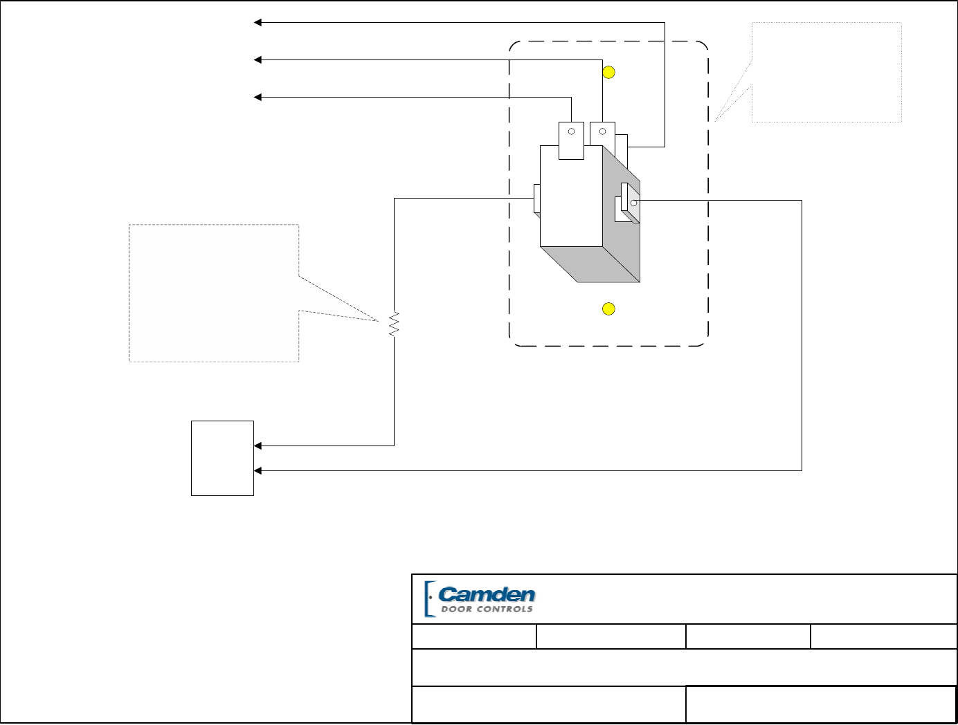
CM-30 Switch Wiring Diagram
SCALE: NONE DRAWN BY: DGW REVISED: 03/20/08
DATE: 02/25/03
Camden Manufacturing 5502 Timberlea Blvd.
Mississauga, Ontario
L4W 2T7
12 - 24 V
AC/DC
Power
for Light
Common
Normally
Open
Normally
Closed Orange
Blue
Grey
Red Black
Rear View of CM-30 switch
and Faceplate
NOTE:
Access to light bulb (or LED) is obtained by first
removing Cherry switch from two plastic retaining
pins. Squeeze white retainer assembly between
finger and thumb, and gently rock back and forth
while pulling free of black threaded portion. Then
pull out light bulb (or LED) to replace.
Note:
A lead with blue-coloured heat
shrink (over in-line resistor) is
supplied on LED model.
A lead with black coloured heat
shrink (over in-line resistor) is
supplied on incandescent bulb
model.
Leave resister on for 24 Volts,
Cut off resister for 12 Volts.
