Cameo Communications DSLR2001N 802.11n WLAN ADSL2+ Router User Manual User s manual
Cameo Communications Inc 802.11n WLAN ADSL2+ Router User s manual
User Manual

TRENDnet DSLR-2001N 1
DSLR-2001N
802.11n WLAN ADSL2+ Router
User’s Manual

TRENDnet DSLR-2001N 2
Table of Contents
Table of ContentsTable of Contents
Table of Contents
Chapter 1: Product Overview...................................... 6
1.1 Features ................................................... 6
1.2 Package Contents ........................................... 7
1.3 Hardware Overview .......................................... 8
Front Panel ............................................. 8
Rear Panel ............................................. 10
1.4 Wireless Considerations ................................... 11
Connection Performance ................................. 11
Security Checklist ..................................... 11
Chapter 2: Installation......................................... 13
2.1 Connect the Power ......................................... 13
2.2 Connect the Computer ...................................... 14
Wired Connection ....................................... 14
2.3 Connect the DSL ........................................... 14
Use a Splitter ......................................... 14
2.4 Check the Installation .................................... 15
Chapter 3: Configure the Computer............................... 16
3.1 Windows 95 / 98 / ME ...................................... 16
3.2 Windows 2000 .............................................. 17
3.3 Windows XP ................................................ 18
3.4 Windows Vista ............................................. 19
3.4 Windows 7 ................................................. 19
Chapter 4: Log In to the Modem Router.......................... 20
4.1 Setup Wizard .............................................. 22
4.2 ........................................................................................................................................Menu
24
Chapter 5: Setup................................................ 25
5.1 Internet Setup ............................................ 25
Internet Connection Settings ........................... 25
Internet Settings ...................................... 26
Protocol ............................................... 26
5.2 Wireless Settings ......................................... 36
Basic Setting .......................................... 36
Security Setting ....................................... 37

TRENDnet DSLR-2001N 3
5.3 Local Network ............................................. 41
LAN .................................................... 41
DHCP Setting ........................................... 42
DHCP Reserved Address .................................. 43
5.4 Time and Date ............................................. 44
Chapter 6: Advanced............................................. 46
6.1 Advanced Wireless ......................................... 46
Wireless Router Settings ............................... 46
MBSSID Settings ........................................ 47
Wireless MAC Filter .................................... 48
WPS Setting ............................................ 49
6.2 Multi-WAN ................................................. 50
DSL Auto Scan .......................................... 50
IP/PPP Config .......................................... 51
Default Route .......................................... 51
6.3 Advanced-LAN .............................................. 52
6.4 ADSL Settings ............................................. 52
6.5 RIP Settings .............................................. 53
6.6 NAT ....................................................... 54
Virtual Server ......................................... 54
Port Trigger ........................................... 55
ALG .................................................... 56
VPN Passthrough ........................................ 58
6.7 Firewall .................................................. 59
MAC Filter ............................................. 59
IP Filter .............................................. 60
URL Filter ............................................. 61
DOS Protection ......................................... 62
Domain Blocking ........................................ 63
DMZ .................................................... 63
SPI Settings ........................................... 64
6.8 Packet Filter ............................................. 65
Filters & Rules ........................................ 65
Statistics ............................................. 67

TRENDnet DSLR-2001N 4
6.9 Static Route .............................................. 67
6.10 Multicast ................................................ 69
6.11 Dynamic DNS .............................................. 70
6.12 Ethernet Setting ......................................... 71
6.13 Port Mapping ............................................. 72
6.14 Quality of Service (QoS) ................................. 74
Queue Management ....................................... 74
Queue Config ........................................... 74
Queue Classification ................................... 76
QoS Status ............................................. 78
6.15 UPnP ..................................................... 79
6.16 SNMP ..................................................... 80
Chapter 7: Maintenance.......................................... 81
7.1 Password .................................................. 81
7.2 Remote Management ......................................... 82
7.3 Remote Access ............................................. 83
7.4 TR069 Setting ............................................. 84
7.5 Init Script ............................................... 87
7.6 SysLog .................................................... 88
7.7 Time Schedule ............................................. 90
7.8 Firmware Upgrade .......................................... 90
7.9 Configuration Backup/Restore .............................. 92
7.10 Ping ..................................................... 93
7.11 Diagnostics .............................................. 94
7.12 Reboot Device ............................................ 94
Chapter 8: Status............................................... 95
8.1 Summary ................................................... 95
8.2 ADSL Info ................................................. 95
8.3 Wireless Clients .......................................... 96
8.4 LAN Clients ............................................... 96
8.5 Logs ...................................................... 97
8.6 Routing Table ............................................. 98
8.7 Traffic Meter ............................................. 98
8.8 Driver Version ............................................ 99
8.9 Statistics ................................................ 99
Basic Statistics ....................................... 99

TRENDnet DSLR-2001N 5
Statistics > DSL Statistics ........................... 100
Appendix....................................................... 101
A. Regulatory & Safety Information ........................... 101
Wireless LAN, Health and Authorization ................ 101
Disclaimers ........................................... 101
FCC (Federal Communications Commission) Statement ..... 102
CE statement .......................................... 105
B. Specifications ............................................ 109
C. Limited Warranty .......................................... 111

Product Overview
TRENDnet DSLR-2001N 6
Chapter 1: Product Overview
Thank you for choosing Trendnet
Wireless N ADSL2 Modem Router.
This Modem Router combines the functionality of an ADSL modem and
Internet gateway in one. It allows you to access the Internet and
share resources such as printers, scanners, and files, via a
wireless connection or through one of the Ethernet ports. The
various security features, such as WPS, WPA2, SPI, and NAT,
protect your data and privacy online. The web-based utility allows
you to configure your Modem Router easily.
1.1 Features
•
Compliant with ADSL G.dmt (G.992.1), G.lite (G.992.2) standards
•
Compliant with ADSL2 G.dmt.bis (G.992.3) and ADSL2 + G.992.5
standards
•
Up to Up to 24Mbps downstream, 1.2Mbps upstream with ADSL2+
service
•
IEEE 802.11b/g/n infrastructure operating modes
•
Supports TR069 remote management
•
Supports web-based configuration
•
Supports Command Line Interface (CLI) via Telnet
•
Supports NAT, DHCP
•
Supports VLAN and QoS
•
Supports firewall protection
•
Supports up to 8 permanent virtual circuits (PVC)
•
Supports Wi-Fi Multimedia (WMM)
•
Supports Wi-Fi Protected Setup (WPS) for easy connection
•
Supports wireless data encryption with 64/128-bit WEP standard
•
Supports enhance security for WPA-TKIP, WPA2-AES, WPA, and WPA2
Product Overview
TRENDnet DSLR-2001N 7
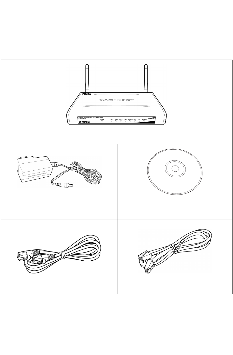
1.2 Package Contents
Check if your package contains the following items. If any item is
missing or appears damaged, contact your dealer.
Modem Router
Power adapter CD-ROM with User’s Guide
RJ-45 Ethernet cable RJ-11 telephone cable
Product Overview
TRENDnet DSLR-2001N 8
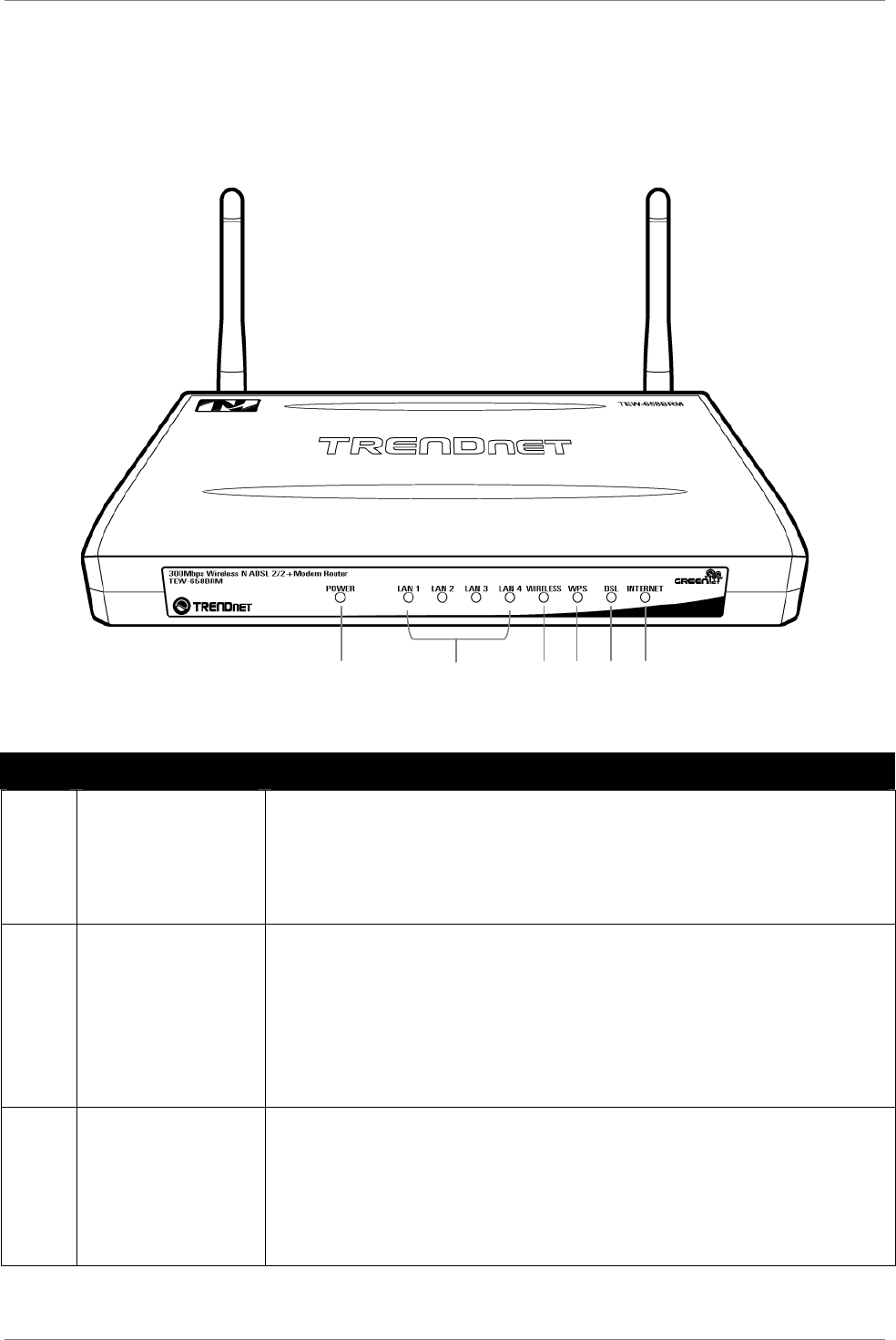
1.3 Hardware Overview
Front Panel
No. LED Description
1 Power LED
Lights up when the device is powered on.
•
Solid GREEN – Indicates normal operation.
•
Solid RED – Indicates malfunction.
•
Off – The device is powered off.
2 LAN 1, 2, 3,
4
Lights up when a computer is connected on the
Ethernet ports (1~4).
•
Solid GREEN – Connected but no activity.
•
Flashing GREEN – Data transmission is in
progress.
•
Off – No computer is connected.
3 Wireless
Lights up to indicate wireless connection.
•
Solid GREEN – Connected but no activity.
•
Flashing GREEN – Data transmission is in
progress.
•
Off – Wireless connection is disabled.
1
2
3
4
5
6

Product Overview
TRENDnet DSLR-2001N 9
No. LED Description
4 WPS
Lights up to indicate the Wireless Protected
Setup (WPS) connection status.
•
Solid GREEN – WPS-enabled device is
connected.
•
Flashing GREEN – Searching for WPS-enabled
devices.
•
Solid RED – No WPS-enabled device is
connected.
•
Off – WPS is disabled.
5 DSL
Lights up to indicate DSL connection status.
•
Flashing GREEN – Attempts to synchronize
with DSL line.
•
Solid GREEN – DSL line is synchronized.
•
Off – DSL connection is not present.
6 Internet
Lights up to indicate Internet connection
status.
•
Solid GREEN – Internet is connected but no
activity.
•
Flashing GREEN – Data transmission is in
progress.
•
Solid RED – Internet connection failed.
•
Off – No internet connection.
Product Overview
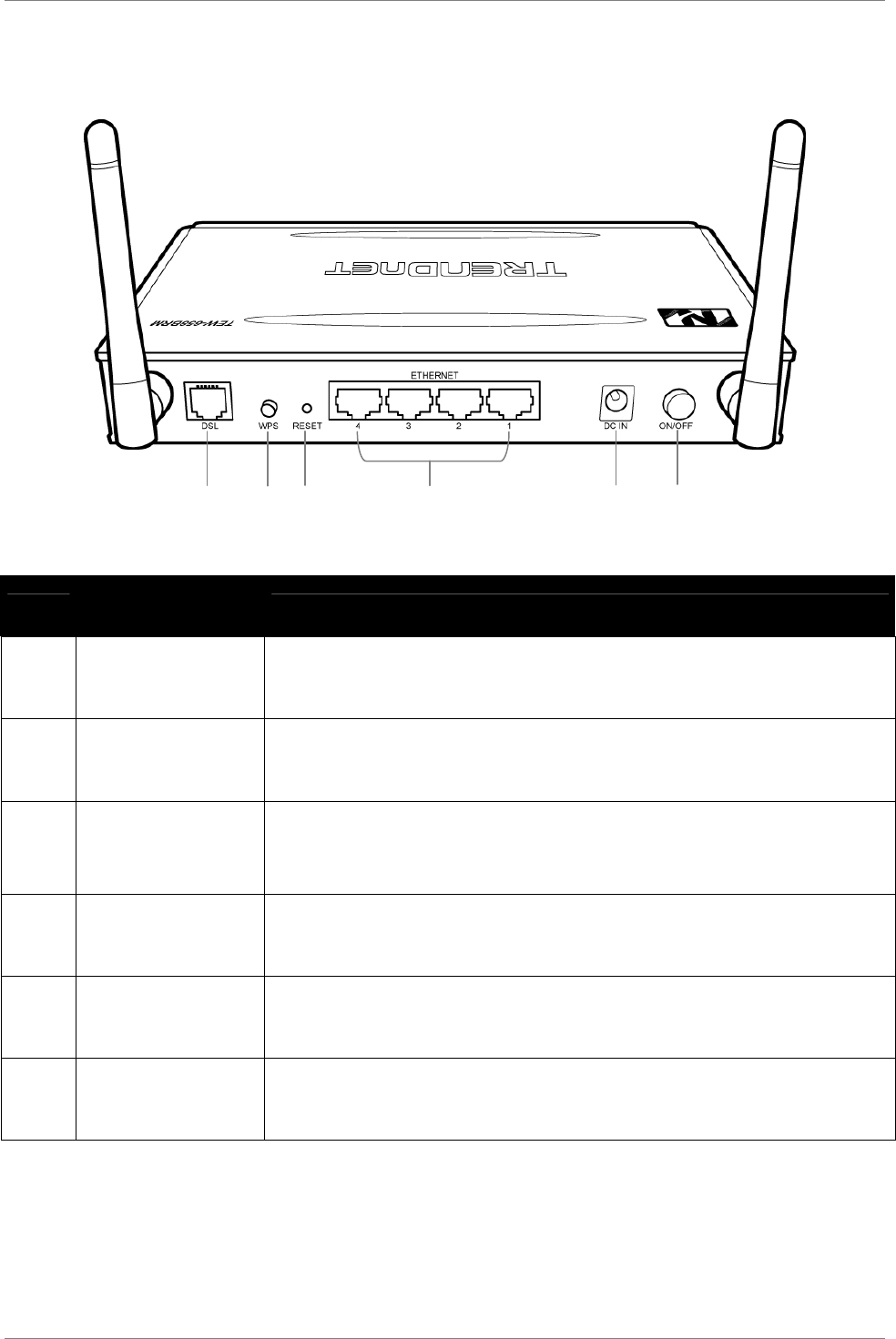
TRENDnet DSLR-2001N 10
Rear Panel
No. Ports /
Buttons Description
1 DSL port Connects to the DSL line using the RJ-11 cable.
2 WPS button Press to search for devices that support Wi-Fi
Protected Setup (WPS).
3 Reset button Press and hold this button for 5 seconds to
restore your device to its original factory
default setting.
4 Ethernet port
1, 2, 3, 4
Connects a computer and other Ethernet network
devices to the Modem Router using RJ-
45 cables.
5 Power port Connects the power adapter.
6 Power button Press to turn your device on or off.
1
2
3
4
5
6

Product Overview
TRENDnet DSLR-2001N 11
1.4 Wireless Considerations
Connection Performance
A number of factors affect the performance of wireless connection.
Consider the following guidelines to ensure high-range and stable
connectivity.
1. Keep the Modem Router and other wireless devices away from
obstructions, such as walls or buildings. Each obstruction
can reduce the range of a wireless device.
2. Keep the Modem Router and other wireless devices away from
devices that produce radio frequency (RF) noise, such as
microwave ovens or radios.
3. Keep the Modem Router and other wireless devices away from
any device operating on the 2.4GHz frequency, such as
cordless phones or remote controls.
4. Antenna orientation affects the wireless signal. Determine
the best orientation and adjust the antenna position of your
device.
Security Checklist
Wireless networks are easy to install and convenient to use.
However, wireless network signals can also be intercepted easily.
To prevent unauthorized users from connecting to your wireless
network, follow the guidelines below.
1. Change the default wireless network name.
Your device has a default Service Set Identifier (SSID) which
is the wireless network name. Change the SSID with a unique
name to identify your network. The SSID can be up to 32
characters in length.
2. Change the default password.
Your device has a default password. You have to enter this
password to change your network settings. Change the password
to prevent unauthorized users from hacking into your network
and changing the settings.
3. Enable MAC address filtering.
Your device supports Media Access Control (MAC) address
filtering. You can assign a MAC address on each computer that
you want to connect to your wireless network. When MAC
address filtering is enabled, only the computers with the
specified MAC addresses are allowed access.
4. Enable encryption

Product Overview
TRENDnet DSLR-2001N 12
Your device supports Wired Equivalent Privacy (WEP), and Wi-
Fi Protected Access (WAP/WPA2) encryption. To ensure a high
level of security, enable the highest security encryption and
use strong passphrases, avoid using words that can be found
in the dictionary.
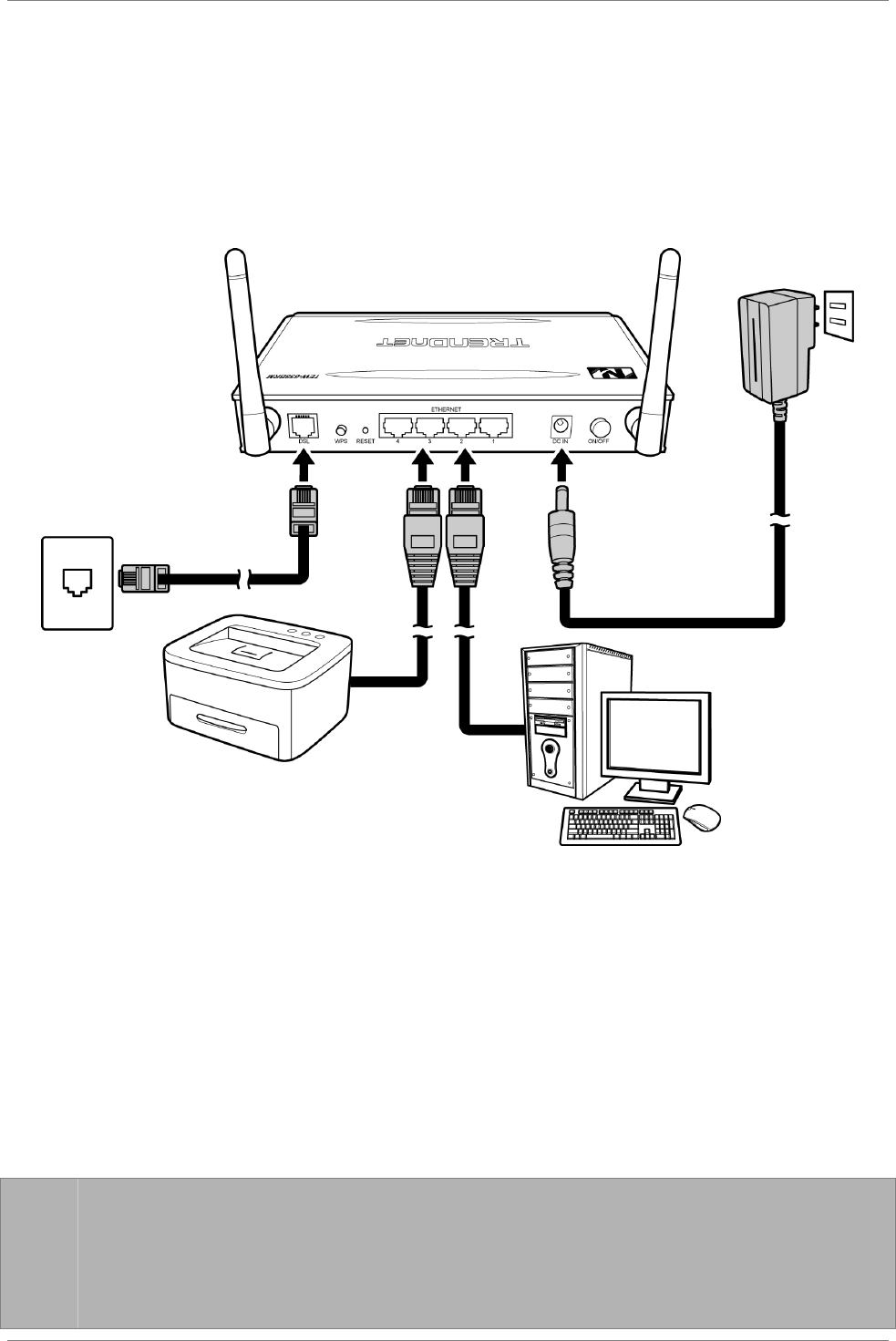
Installation
TRENDnet DSLR-2001N 13
Chapter 2: Installation
Make sure that all devices are powered off before starting
installation.
Installation Diagram
2.1 Connect the Power
1. Connect the power adapter to the power port of your Modem
Router.
2. Plug the power adapter to a wall outlet or a power strip.
☞
☞☞
☞
NOTE:
•
Use only the supplied power adapter. Using other power
adapters may cause damage to the device.
•
Connect all devices to your Modem Router before connecting
the power adapter to a wall outlet.
Installation
TRENDnet DSLR-2001N 14
2.2 Connect the Computer
Wired Connection
1. Connect one end of the RJ-45 cable to one of the Ethernet (1,
2, 3, 4) ports of your Modem Router.
2. Connect the other end of the RJ-45 cable to the Ethernet port
of the computer.
Repeat the above steps to connect other computers to the
Modem Router via Ethernet connection.
To connect more than four computers, use a hub or switch. Connect
one end of an RJ-45 cable to the hub or switch and the other end
to the computer.
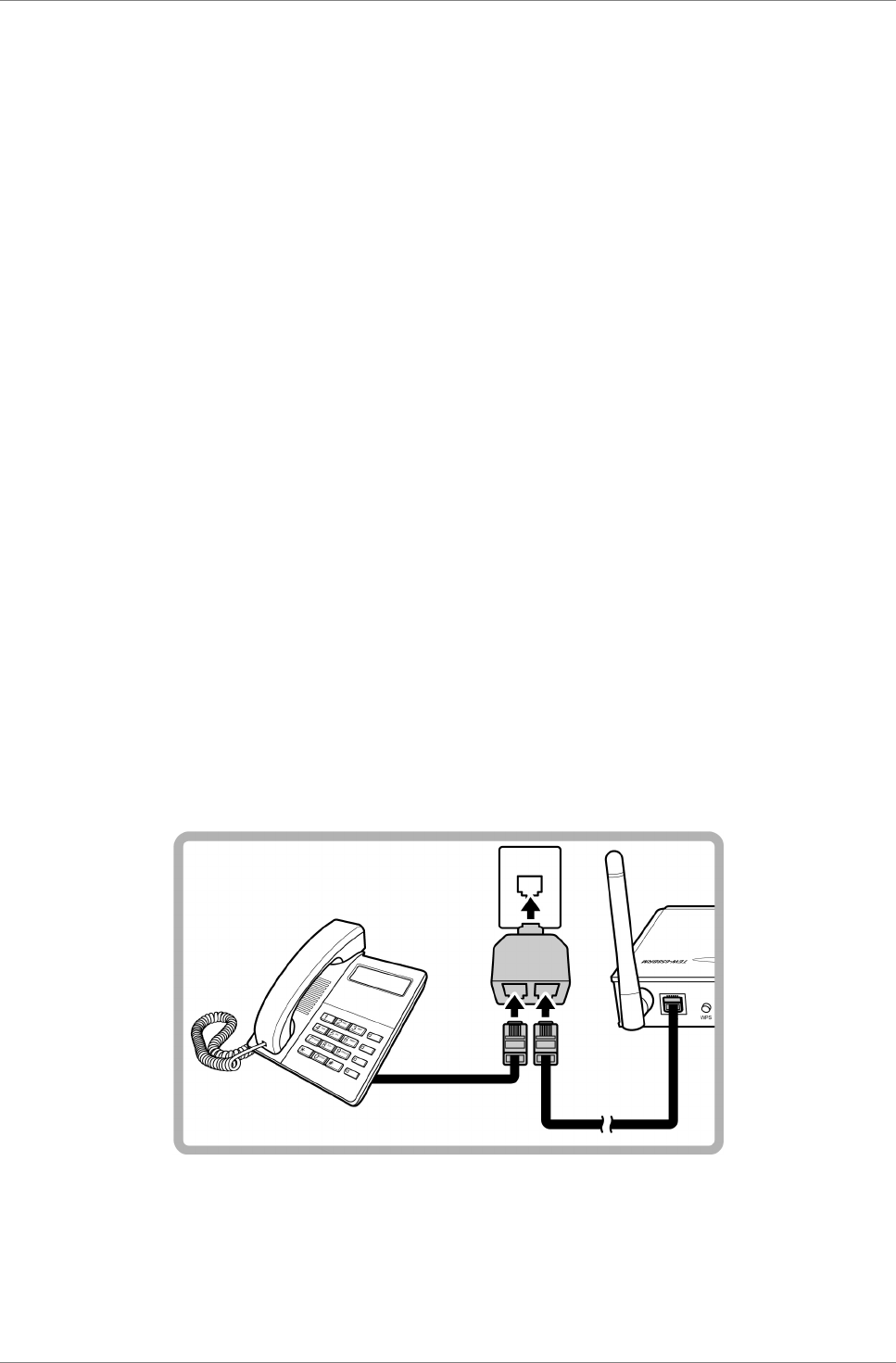
2.3 Connect the DSL
1. Connect one end of the RJ-11 cable to the DSL port of your
Modem Router.
2. Connect the other end of the RJ-11 cable to a wall jack with
DSL service.
Use a Splitter
You need a splitter when connecting the Modem Router to the wall
jack that also connects to a telephone.
1. Plug the splitter to the wall jack with DSL service.
2. Connect one end of the RJ-11 cable to the DSL port of your
Modem Router.
3. Connect the other end of the RJ-11 cable to the MODEM port of
the splitter.

Installation
TRENDnet DSLR-2001N 15
4. Connect the telephone to the LINE port of the splitter using
another RJ-11 cable.
2.4 Check the Installation
To ensure that all devices are properly connected, check the LED
indicators on the front of your Modem Router. For basic
installation, the following LED must be lit:
√
Power LED
√
LAN LED (for every computer that is connected via Ethernet
connection)
√
DSL LED
The lighted LED indicators vary depending on the type of
connection that you make. See “Front Panel” on page 8 for more
information about the LED indicators.

Configure the Computer
TRENDnet DSLR-2001N 16
Chapter 3:
Configure the Computer
This chapter will guide you on how to configure your computer
according to the operating system you are using.
•
Windows
95 / 98 / ME, see below.
•
Windows
2000, see page 17.
•
Windows
XP, see page 18.
•
Windows
Vista, see page 19.
•
Windows
7, see page 19.
3.1 Windows 95 / 98 / ME
If you are using Windows
95 / 98 / ME operating system, follow
the instructions below to configure your computer.
1. On the desktop, right-click Network Neighborhood.
2. Click Properties.
3. On the IP Address tab, select Obtain an IP Address
automatically.
4. On the DNS Configuration tab, select Disable DNS.
5. On the Gateway tab, leave all fields blank.
6. Click OK.
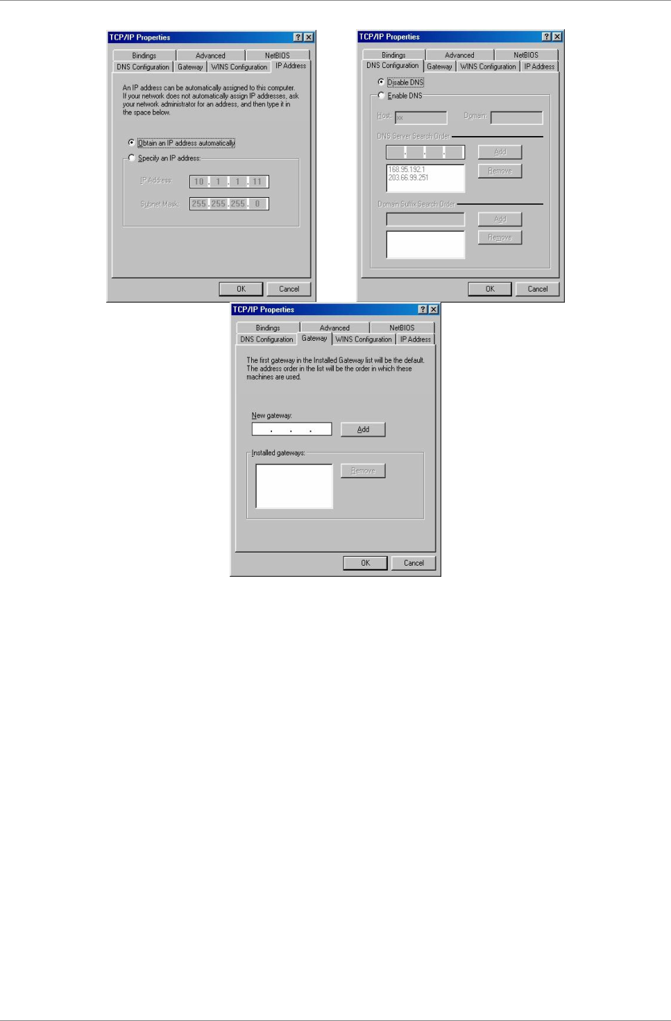
Configure the Computer
TRENDnet DSLR-2001N 17
IP Address Page DNS Configuration Page
Gateway Page
3.2 Windows 2000
If you are using Windows
2000, follow the instructions below to
configure your computer.
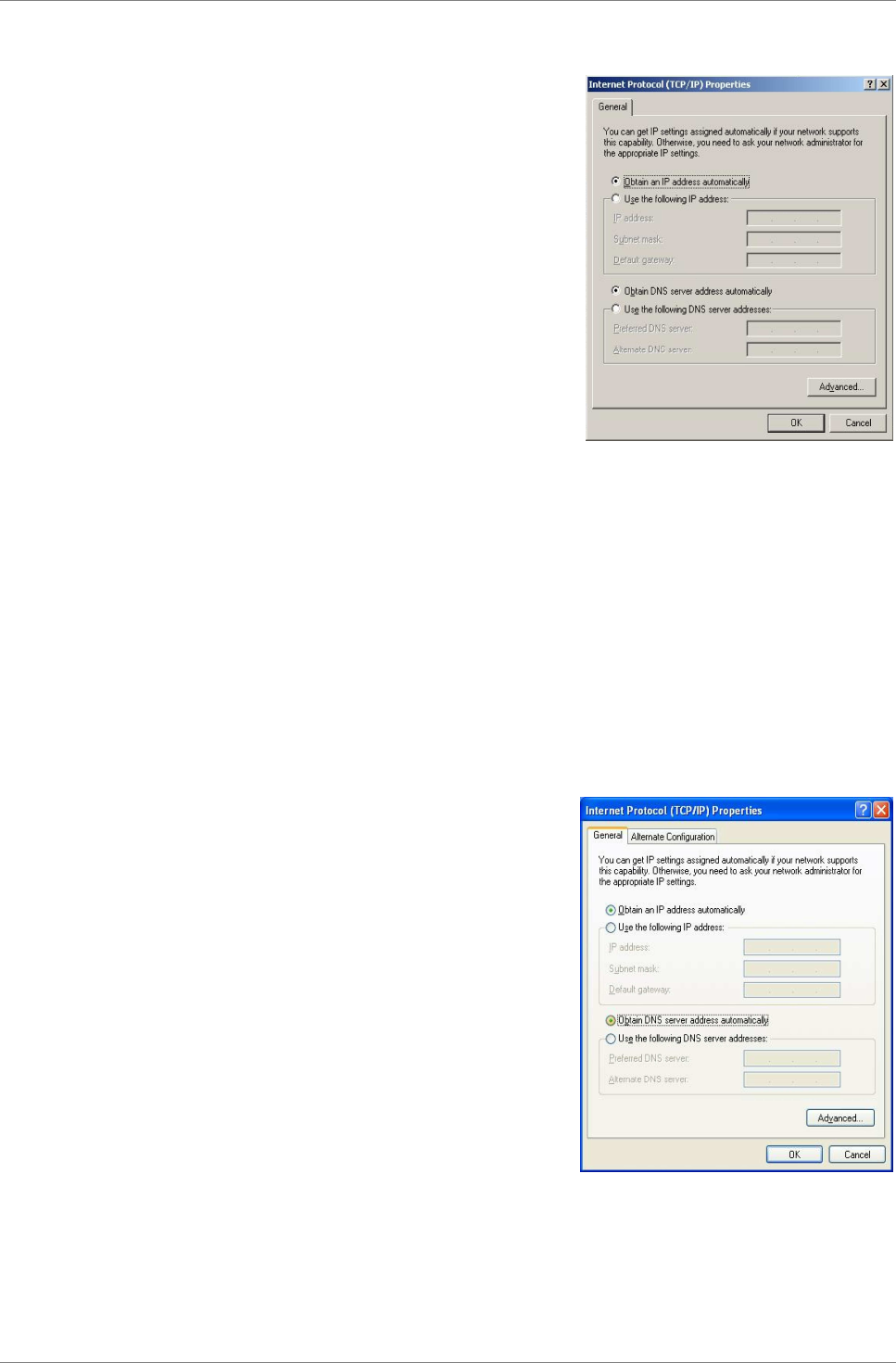
Configure the Computer
TRENDnet DSLR-2001N 18
1. Click Start > Settings > Control
Panel > Network and Dial-up
Connections.
2. Double-click Local Area
Connection.
3. Click Properties.
4. On the network components list,
make sure that Internet Protocol
(TCP/IP) is checked. If not, check
it to enable the Properties
button.
5. Select Internet Protocol (TCP/IP),
and then click Properties.
6. On the General tab, select Obtain
an IP Address automatically and
Obtain DNS server address
automatically.
7. Click OK.
General Page
3.3 Windows XP
If you are using Windows
XP, follow the instructions below to
configure your computer.
1. Click Start > Control Panel >
Network Connections.
2. Right-click Local Area Connection,
then click Properties.
3. On the network components list,
make sure that Internet Protocol
(TCP/IP) is checked. If not, check
it to enable the Properties
button.
4. Select Internet Protocol (TCP/IP),
and then click Properties.
5. On the General tab, select Obtain
an IP Address automatically and
Obtain DNS server address
automatically.
6. Click OK.
General Page
Configure the Computer
TRENDnet DSLR-2001N 19
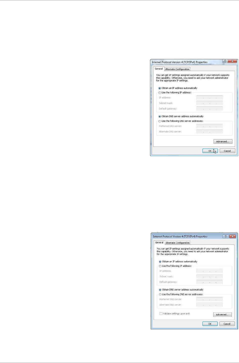
3.4 Windows Vista
If you are using Windows
Vista, follow the instructions below to
configure your computer.
1. Click Start > Control Panel >
Network and Internet Connections >
Network Connections.
2. Right-click Local Area Connection,
then click Properties.
3. On the General tab, make sure that
Internet Protocol (TCP/IP) is
checked. If not, check it to
enable the Properties button.
4. Select Internet Protocol (TCP/IP),
and then click Properties.
5. Select Obtain an IP Address
automatically and Obtain DNS
server address automatically.
6. Click OK.
General Page
3.4 Windows 7
If you are using Windows
7, follow the instructions below to
configure your computer.
1. Click Start > Control Panel >
Network & Sharing Center.
2. Click Local Area Connection.
3. Click Properties.
4. On the network components list,
make sure that Internet Protocol
(TCP/IP) is checked. If not, check
it to enable the Properties
button.
5. Select Internet Protocol (TCP/IP),
and then click Properties.
6. On the General tab, select Obtain
an IP Address automatically and
Obtain DNS server address
automatically.
7. Click OK.
General Page

Log In to the Modem Router
TRENDnet DSLR-2001N 20
Chapter 4:
Log In to the Modem Router
Use the web-based utility to configure your Modem Router.
Note the following default settings before accessing the web-based
utility.
SSID
TRENDnet658
Channel
Auto
802.11 Mode
802.11 b+g+n mixed mode
Security
Disable
IP Address
192.168.10.1
VPI/VCI for
ATM
8/35
DSL Line Mode
Auto-detect
TCP/IP Address
(PC)
192.168.10.x (where x is a number between 2
and 254)
Default IP
Address (Modem
Router)
192.168.10.1
Subnet Mask
255.255.255.0
Do the following instructions to log in to the Modem Router:
1. Launch the web browser.
2. On the address bar, enter http://192.168.10.1, then press
Enter.
3. Enter the User name and Password.
The default user name and password are “admin”. It is advised
to change the user name and password, see “7.1 Password”
on page 81.

Log In to the Modem Router
TRENDnet DSLR-2001N 21
Log In to the Modem Router
TRENDnet DSLR-2001N 22
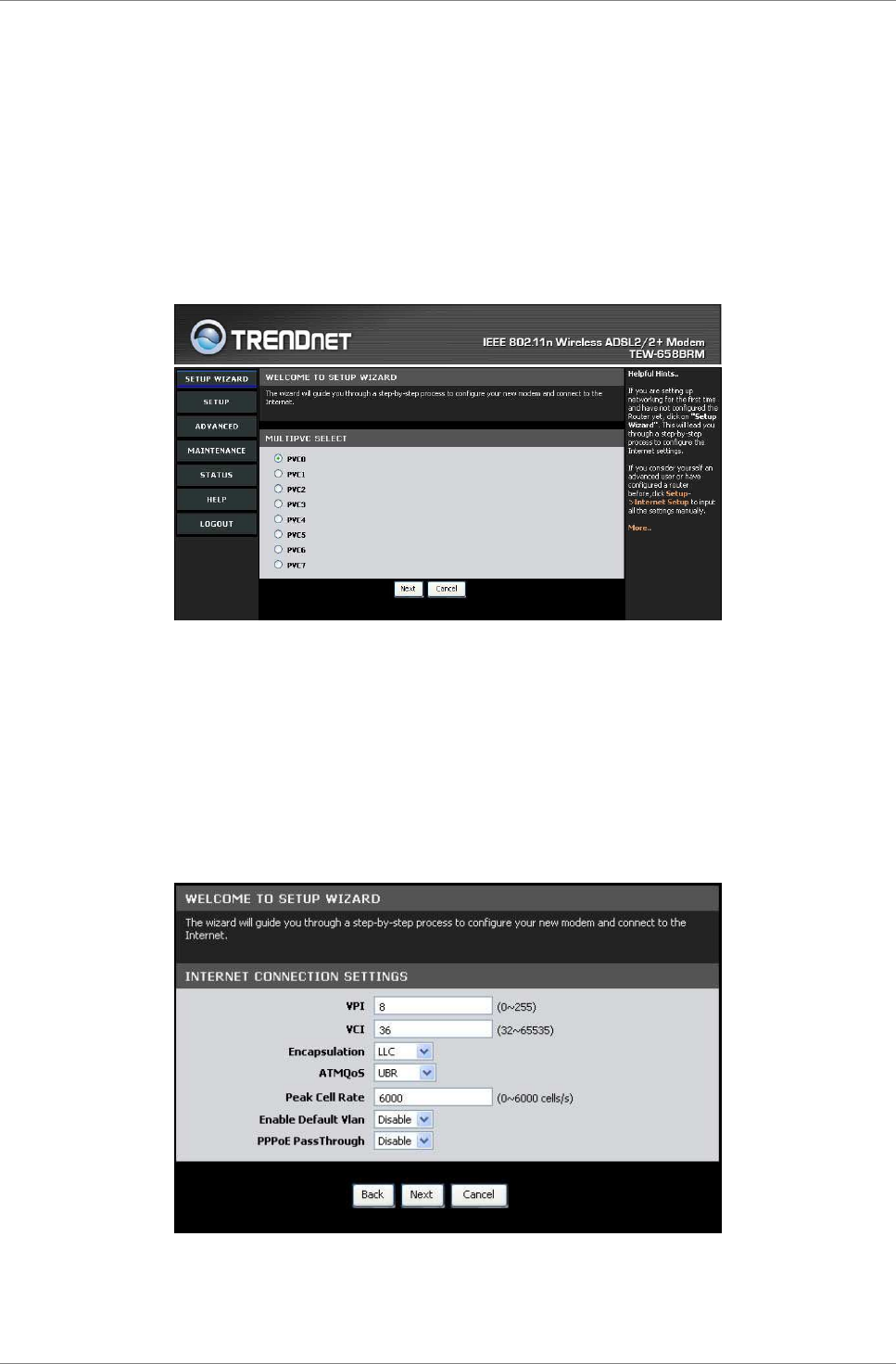
4.1 Setup Wizard
After you log in, the Setup Wizard appears on the screen. It is
recommended to follow the wizard if are setting up the network and
configuring the Modem Router for the first time.
1. Select a PVC (Permanent Virtual Circuit), then click Next.
It is recommended to use the default setting, PVC0, when
setting up the Modem Router for the first time.
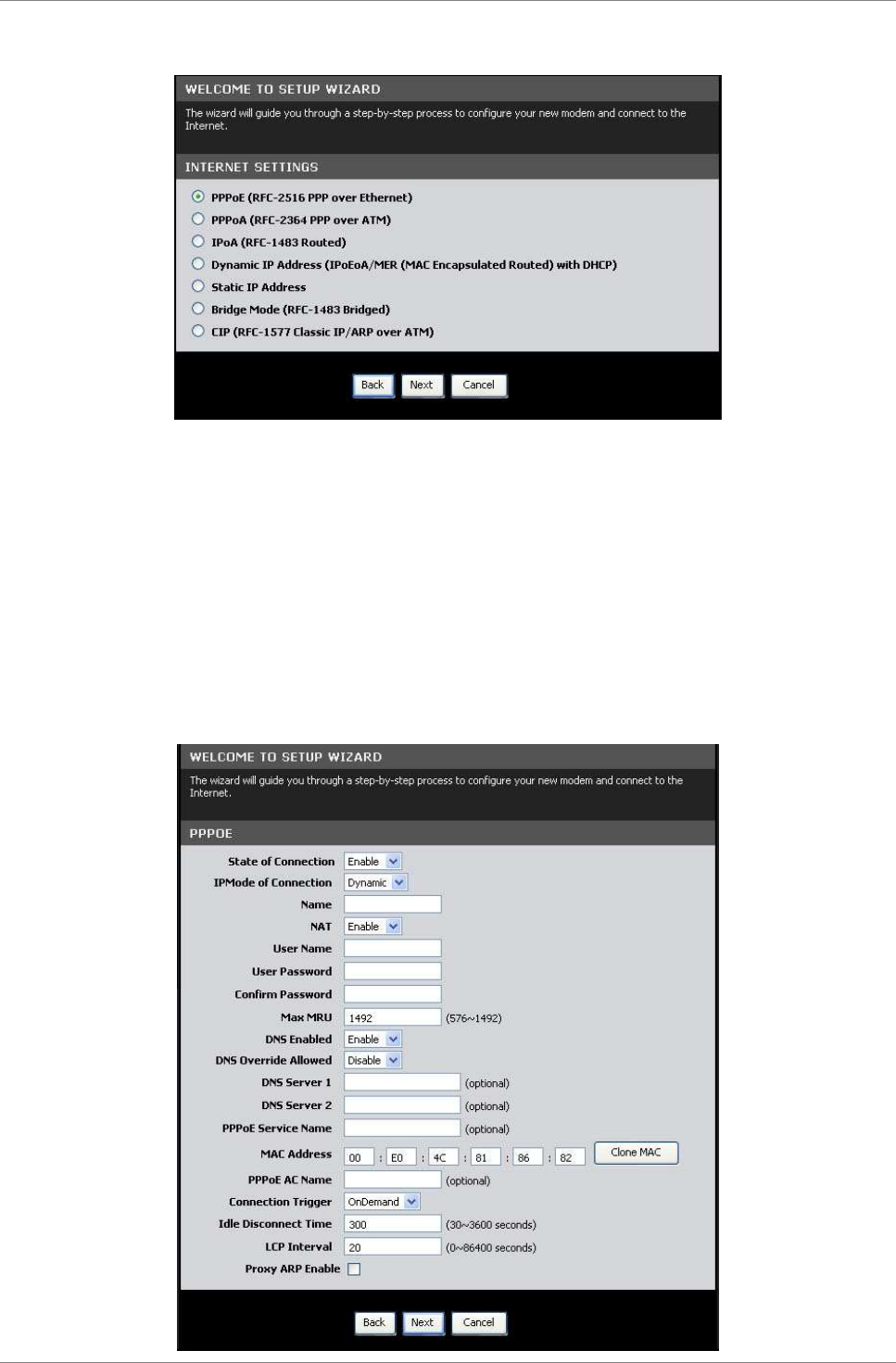
2. The information required on the page below can be obtained
from your Internet service provider (ISP). Consult your ISP
and do the following:
a. Enter the Virtual Path Identifier (VPI) and Virtual
Channel Identifier (VCI).
b. Set the Encapsulation mode, ATMQoS, and Peak Cell Rate.
c. Enable or disable Default VLAN and PPPoE PassThrough.
d. Click Next to continue.
Log In to the Modem Router
TRENDnet DSLR-2001N 23
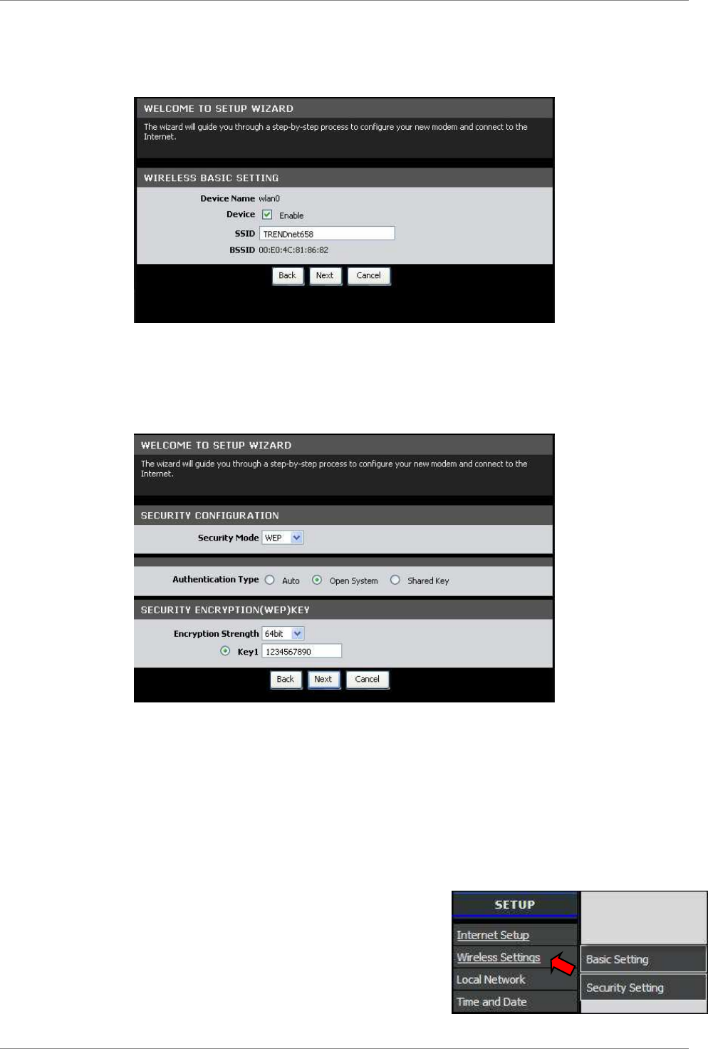
3. Select a network protocol. Click Next to continue.
The information required on the next page vary depending on
the network protocol you selected here.
4. The following is a PPPoE example.
a. Enter the connection Name, User Name, and User Password.
Re-type the password in the Confirm Password field.
b. Select whether to enable or disable features such as NAT
(Network Address Translation), DNS (Domain Name System),
and DNS Override.
c. Leave the remaining fields to their default settings.
d. Click Next to continue.
Log In to the Modem Router
TRENDnet DSLR-2001N 24
5. Select whether to enable or disable wireless connection. From
this point, you can also change the SSID with a name that you
can easily remember. Click Next to continue.
6. Select the Security Mode, Authentication Type, and Encryption,
and enter a passkey. Click Next to continue.
The screen below varies depending on the security mode you
selected, below is an example of a WEP security screen.
7. When prompted to reboot, click OK.
8. Log out from the web-based utility, then log in again to
apply the configurations.
4.2 Menu
Use the main menu, located on the left
panel of the screen, to manually configure
your Modem Router. Click a menu item, then
a submenu to display the page on the
screen.
For submenus with more options, move the
mouse cursor over the submenu to view the
options.
Setup
TRENDnet DSLR-2001N 25
Chapter 5: Setup
The Setup menu allows you to configure the Internet connection of
your Modem Router manually.
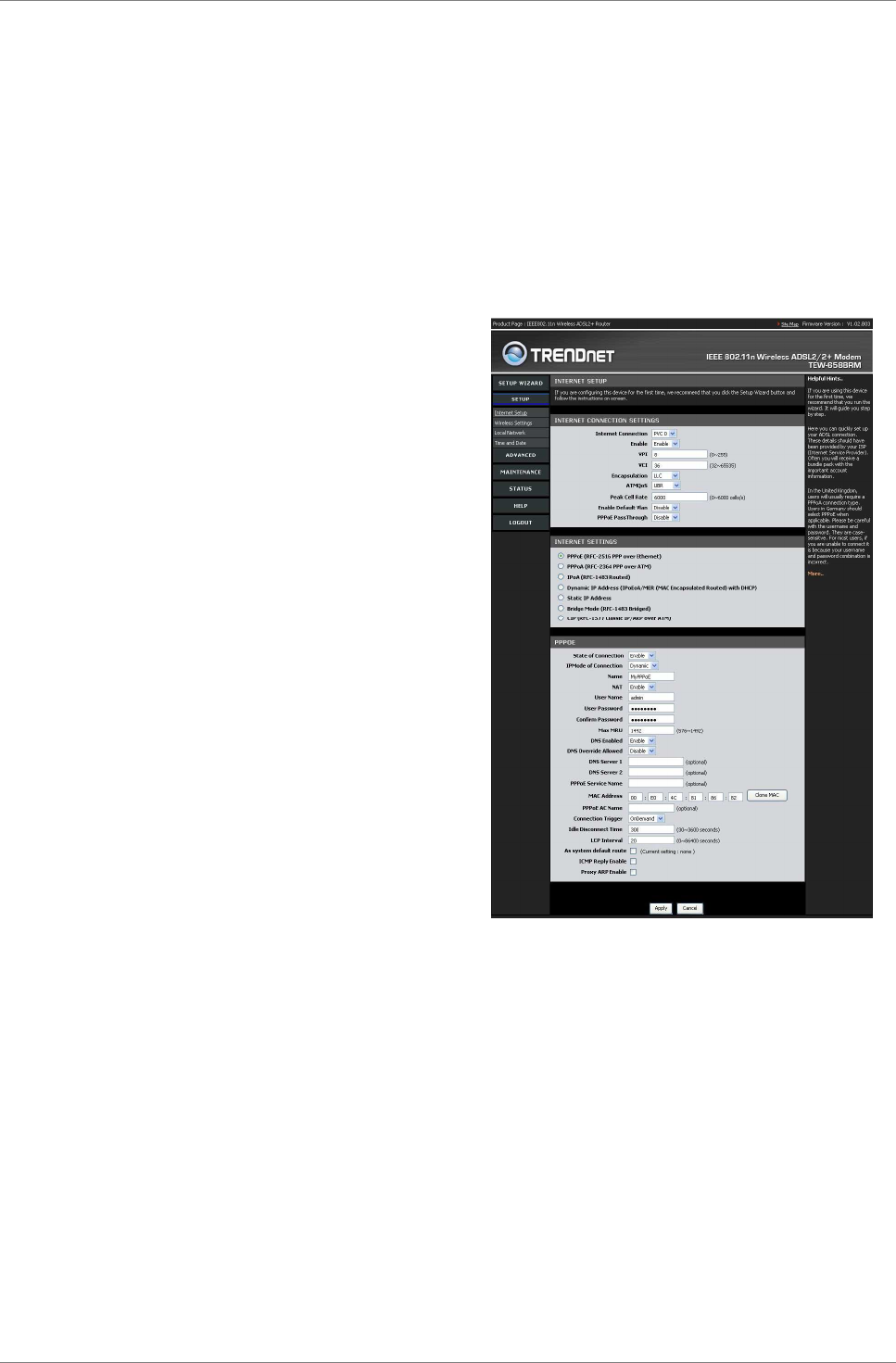
5.1 Internet Setup
The Internet Setup page is divided
into three sections: Internet
Connection Settings, Internet
Settings, and Protocol.
To access the Internet Setup page,
click SETUP > Internet Setup.
Internet Connection
Settings
This setting configures the Modem
Router to your Internet connection.
The required settings should be
obtained from your ISP.
Internet Connection — Select the
Permanent Virtual Circuit (PVC).
The Modem Router supports up to 8
PVCs.
Enable — Select whether to enable
or disable the Internet connection.
VPI — Enter the Virtual Path
Identifier (VPI) provided by your
ISP. The default VPI is 8.
VCI — Enter the Virtual Channel Identifier (VCI)) setting provided
by your ISP. The default VCI is 36.
Encapsulation — Select LLC (Logical Link Control) or VCMUX
(Virtual Circuit Multiplexing), according to your ISP.
ATMQoS — Select the type of ATM Queue of Service (ATMQoS)
specified by your ISP. Options are: UBR (Unspecified Bit Rate),
CBR (Constant Bit Rate), VBR-nrt (Variable Bit Rate non-real-time),
and VBR-rt (Variable Bit Rate real-time).
Peak Cell Rate — This is the maximum rate of cells that you can
send. If provided by your ISP, enter the rate in the field.
Otherwise, leave this field to its default setting.
Enable Default Vlan — Select whether to enable or disable VLAN
tagging.

Setup
TRENDnet DSLR-2001N 26
PPPoE PassThrough — Select whether to enable or disable PPPoE
passthrough.
Internet Settings
DSL lines use different network protocols to establish Internet
connection. Ask your ISP and select the protocol used by your DSL
line, options are:
•
PPPoE (RFC-2516 PPP over Ethernet)
•
PPPoA (RFC-2364 PPP over ATM)
•
IPoA (RFC-1483 Routed)
•
Dynamic IP Address (IPoEoA/MER (MAC Encapsulated Routed) with
DHCP)
•
Static IP Address
•
Bridge Mode (RFC-1483 Bridged)
•
CIP (RFC-1577 Classic IP/ARP over ATM)
Protocol
This section varies depending on the selected network protocol.
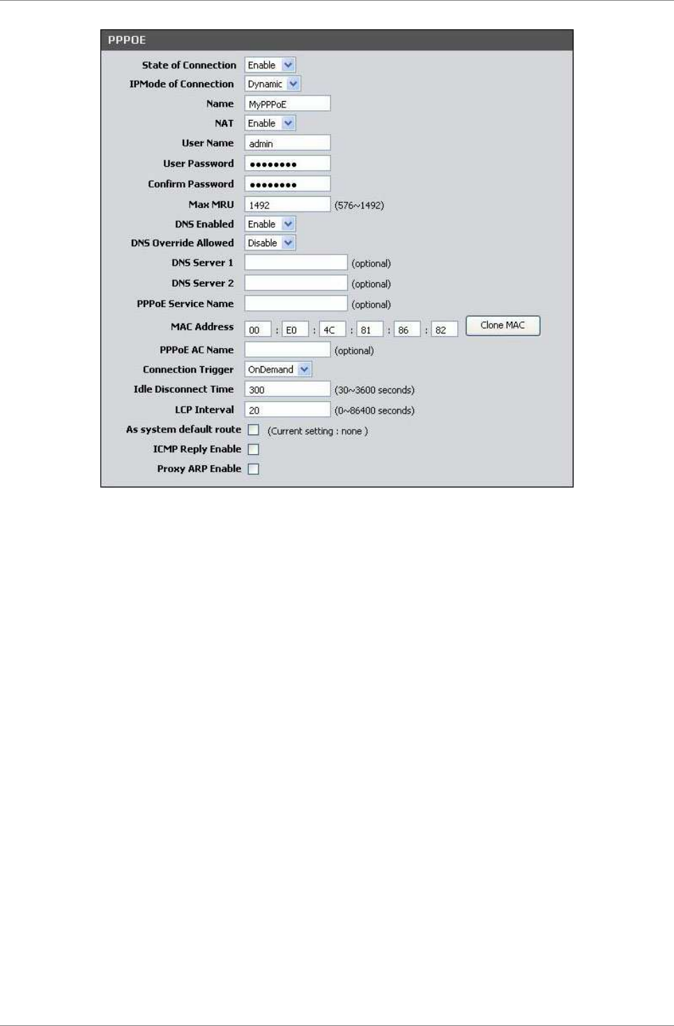
PPPoE (RFC-2516 PPP over Ethernet)
If you select PPPoE (Point-to-Point Protocol over Ethernet), the
screen below is displayed.
Setup
TRENDnet DSLR-2001N 27
State of Connection — Select whether to enable or disable this
connection.
IPMode of Connection — Select the connection mode, options are:
•
Dynamic: Select Dynamic if the IP address can be
automatically obtained from your ISP.
•
Static: Select Static if you are required to use a
permanent IP address to connect to the Internet. You must
enter the IP Address and Subnet Mask provided by your ISP.
Name — Enter your desired connection name.
NAT — Select whether to enable or disable NAT (Network Address
Translation). Enable this setting to share one WAN IP address with
multiple computers on your network.
User Name — Enter the user name provided by your ISP.
User Password — Enter the password provided by your ISP. Re-enter
the password in the Confirm Password field.
Max MRU — This is the maximum rate of cells that you can receive.
If provided by your ISP, enter the rate in the field. Otherwise,
leave this field to its default setting.
DNS Enabled — Select whether to enable or disable DNS (Domain Name
System).
DNS Override Allowed — Select whether to enable or disable DNS
override.

Setup
TRENDnet DSLR-2001N 28
DNS Server 1 and DNS Server 2 — If provided by your ISP, enter the
DNS server. Otherwise, leave these fields blank.
PPPoE Service Name — Enter a PPPoE service name.
MAC Address — Displays the cloned MAC address. Click the Clone Mac
button to clone the MAC address of your computer.
PPPoE AC Name — Enter the PPPoE account name provided by your ISP.
Connection Trigger — You can configure how you want your Modem
Router to connect and terminate the Internet connection. Options
are:
•
OnDemand: Enables the Modem Router to cut off the Internet
connection after being idle for a specified period of time.
The Modem Router automatically re-establishes the
connection when you try to access the Internet again. On
the Idle Disconnect Time field, enter the number of seconds
that you want to elapse before your Modem Router terminates
the Internet connection.
•
AlwaysOn: Enables the Modem Router to be connected to the
Internet at all times. If you are disconnected, the Modem
Router will automatically re-establish the connection.
•
Manual: With this setting, you have to enter the user name
and password to establish the Internet connection.
LCP Interval — Enter the number of seconds that you want to be the
interval in sending LCP (Link Control Protocol) packets.
As system default route — Check this box to set the current
setting as the default route.
ICMP Reply Enable — Check this box to enable ICMP (Internet
Control Message Protocol) messages to be sent back to the host
that sent the message.
Proxy ARP Enable — Check this box to enable proxy ARP function.
Click the Apply button to save your changes or click the Cancel
button to discard your changes.
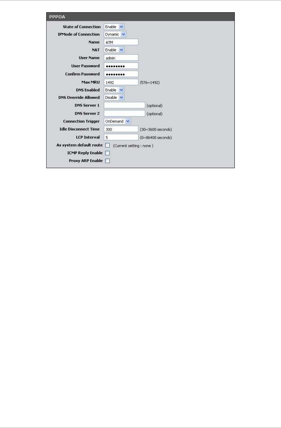
PPPoA (RFC-2364 PPP over ATM)
If you select PPPoA (Point-to-Point Protocol over ATM), the screen
below is displayed.
Setup
TRENDnet DSLR-2001N 29
State of Connection — Select whether to enable or disable this
connection.
IPMode of Connection — Select the connection mode, options are:
•
Dynamic: Select Dynamic if the IP address can be
automatically obtained from your ISP.
•
Static: Select Static if you are required to use a
permanent IP address to connect to the Internet. You must
enter the IP Address and Subnet Mask provided by your ISP.
Name — Enter your desired connection name.
NAT — Select whether to enable or disable NAT (Network Address
Translation). Enable this setting to share one WAN IP address with
multiple computers on your network.
User Name — Enter the user name provided by your ISP.
User Password — Enter the password provided by your ISP. Re-enter
the password in the Confirm Password field.
Max MRU — This is the maximum rate of cells that you can receive.
If provided by your ISP, enter the rate in the field. Otherwise,
leave this field to its default setting.
DNS Enabled — Select whether to enable or disable DNS (Domain Name
System).
DNS Override Allowed — Select whether to enable or disable DNS
override.
DNS Server 1 and DNS Server 2 — If provided by your ISP, enter the
DNS server. Otherwise, leave these fields blank.

Setup
TRENDnet DSLR-2001N 30
Connection Trigger — You can configure how you want your Modem
Router to connect and terminate the Internet connection. Options
are:
•
OnDemand: Enables the Modem Router to cut off the Internet
connection after being idle for a specified period of time.
The Modem Router automatically re-establishes the
connection when you try to access the Internet again. On
the Idle Disconnect Time field, enter the number of seconds
that you want to elapse before your Modem Router terminates
the Internet connection.
•
AlwaysOn: Enables the Modem Router to be connected to the
Internet at all times. If you are disconnected, the Modem
Router will automatically re-establish the connection.
•
Manual: With this setting, you have to manually restore the
connection if you are disconnected.
LCP Interval — Enter the number of seconds that you want to be the
interval in sending LCP (Link Control Protocol) packets.
As system default route — Check this box to set the current
setting as the default route.
ICMP Reply Enable — Check this box to enable ICMP (Internet
Control Message Protocol) messages to be sent back to the host
that sent the message.
Proxy ARP Enable — Check this box to enable proxy ARP function.
Click the Apply button to save your changes or click the Cancel
button to discard your changes.
Setup
TRENDnet DSLR-2001N 31
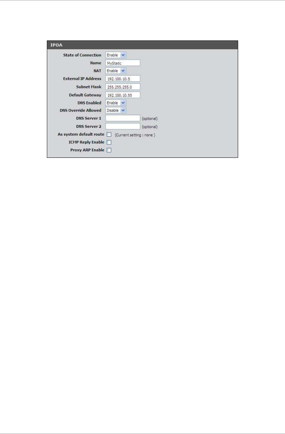
IPoA (RFC-1483 Routed)
If you select IPoA (IP over ATM), the screen below is displayed.
State of Connection — Select whether to enable or disable this
connection.
Name — Enter your desired connection name.
NAT — Select whether to enable or disable NAT (Network Address
Translation). Enable this setting to share one WAN IP address with
multiple computers on your network.
External IP Address — Enter the IP address provided by your ISP.
Subnet Mask — Enter the subnet mask provided by your ISP.
Default Gateway — Enter the default gateway provided by your ISP.
DNS Enabled — Select whether to enable or disable DNS (Domain Name
System).
DNS Override Allowed — Select whether to enable or disable DNS
override.
DNS Server 1 and DNS Server 2 — If provided by your ISP, enter the
DNS server. Otherwise, leave these fields blank.
As system default route — Check this box to set the current
setting as the default route.
ICMP Reply Enable — Check this box to enable ICMP (Internet
Control Message Protocol) messages to be sent back to the host
that sent the message.
Proxy ARP Enable — Check this box to enable proxy ARP function.
Click the Apply button to save your changes or click the Cancel
button to discard your changes.
Setup
TRENDnet DSLR-2001N 32
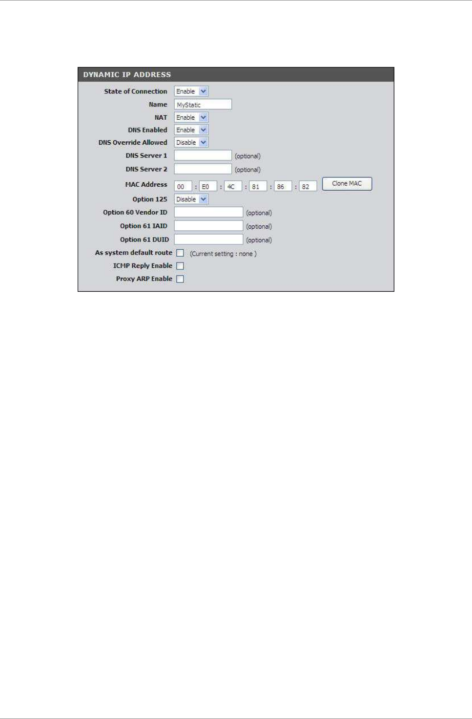
Dynamic IP Address
If you select Dynamic IP Address, the screen below is displayed.
State of Connection — Select whether to enable or disable this
connection.
Name — Enter your desired connection name.
NAT — Select whether to enable or disable NAT (Network Address
Translation). Enable this setting to share one WAN IP address with
multiple computers on your network.
DNS Enabled — Select whether to enable or disable DNS (Domain Name
System).
DNS Override Allowed — Select whether to enable or disable DNS
override.
DNS Server 1 and DNS Server 2 — If provided by your ISP, enter the
DNS server. Otherwise, leave these fields blank.
MAC Address — Displays the cloned MAC address. Click the Clone Mac
button to clone the MAC address of your computer.
Option 125 — Select whether to enable or disable Option 125.
Option 60 Vendor ID — Enter option 60 vendor ID.
Option 61 IAID — Enter option 61 IAID.
Option 61 DUID — Enter option 61 DUID.
As system default route — Check this box to set the current
setting as the default route.
ICMP Reply Enable — Check this box to enable ICMP (Internet
Control Message Protocol) messages to be sent back to the host
that sent the message.
Proxy ARP Enable — Check this box to enable proxy ARP function.

Setup
TRENDnet DSLR-2001N 33
Click the Apply button to save your changes or click the Cancel
button to discard your changes.
Setup
TRENDnet DSLR-2001N 34
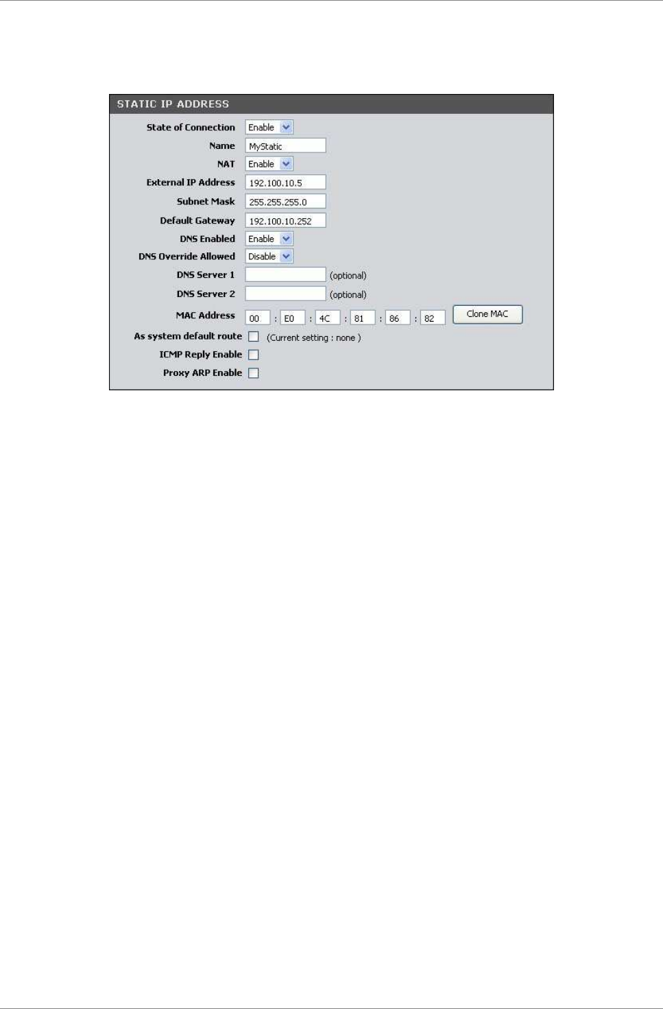
Static IP Address
If you select Static IP Address, the screen below is displayed.
State of Connection — Select whether to enable or disable this
connection.
Name — Enter your desired connection name.
NAT — Select whether to enable or disable NAT (Network Address
Translation). Enable this setting to share one WAN IP address with
multiple computers on your network.
External IP Address — Enter the IP address provided by your ISP.
Subnet Mask — Enter the subnet mask provided by your ISP.
Default Gateway — Enter the default gateway provided by your ISP.
DNS Enabled — Select whether to enable or disable DNS (Domain Name
System).
DNS Override Allowed — Select whether to enable or disable DNS
override.
DNS Server 1 and DNS Server 2 — If provided by your ISP, enter the
DNS server. Otherwise, leave these fields blank.
MAC Address — Displays the cloned MAC address. Click the Clone Mac
button to clone the MAC address of your computer.
As system default route — Check this box to set the current
setting as the default route.
ICMP Reply Enable — Check this box to enable ICMP (Internet
Control Message Protocol) messages to be sent back to the host
that sent the message.
Proxy ARP Enable — Check this box to enable proxy ARP function.
Click the Apply button to save your changes or click the Cancel
button to discard your changes.
Setup
TRENDnet DSLR-2001N 35
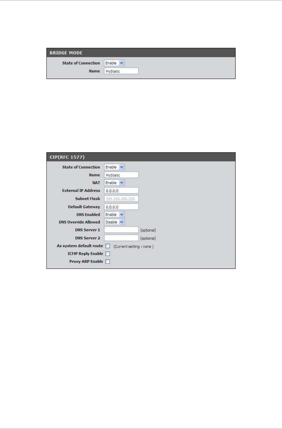
Bridge Mode
If you select Bridge mode (RFC-1483 Bridged), the screen below is
displayed.
State of Connection — Select whether to enable or disable this
connection.
Name — Enter your desired connection name.
CIP (RFC-1577)
If you select CIP (RFC-1577 Classic RP/ARP over ATM), the screen
below is displayed.
State of Connection — Select whether to enable or disable this
connection.
Name — Enter your desired connection name.
NAT — Select whether to enable or disable NAT (Network Address
Translation). Enable this setting to share one WAN IP address with
multiple computers on your network.
External IP Address — Enter the IP address provided by your ISP.
Subnet Mask — Enter the subnet mask provided by your ISP.
Default Gateway — Enter the default gateway provided by your ISP.
DNS Enabled — Select whether to enable or disable DNS (Domain Name
System).
DNS Override Allowed — Select whether to enable or disable DNS
override.
DNS Server 1 and DNS Server 2 — If provided by your ISP, enter the
DNS server. Otherwise, leave these fields blank.
Setup
TRENDnet DSLR-2001N 36
As system default route — Check this box to set the current
setting as the default route.
ICMP Reply Enable — Check this box to enable ICMP (Internet
Control Message Protocol) messages to be sent back to the host
that sent the message.
Proxy ARP Enable — Check this box to enable proxy ARP function.
Click the Apply button to save your changes or click the Cancel
button to discard your changes.
5.2 Wireless Settings
The Wireless Settings page allows you to enable and configure
wireless connections.
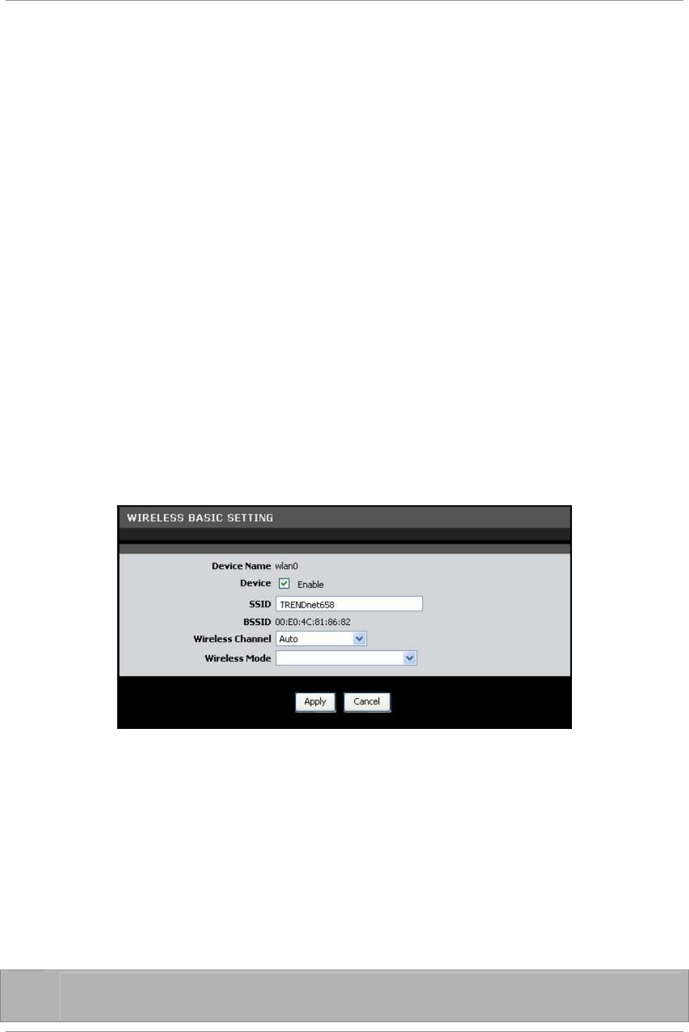
Basic Setting
The Basic Settings page allows you to enable the wireless function
of your Modem Router and set its SSID.
To access the Basics Settings page, click SETUP > Wireless
Settings > Basic Setting or click the Wireless Setting button.
Device — Check this box to enable the wireless function of your
Modem Router.
SSID – Enter the service set identifier (SSID) or the name of your
wireless network. The SSID is case-sensitive and must not exceed
32 alphanumeric characters.
BSSID — (Basic Service Set Identifier) Displays the MAC address of
your Modem Router.
Wireless Channel — Select the appropriate channel that corresponds
to your network settings. You should assign different channels for
each access point to avoid signal interference.
✌
TIP: Select Auto for Wireless Channel to allow your Modem
Router to select the best possible channel for your wireless
Setup
TRENDnet DSLR-2001N 37
network.
Wireless Mode — Select the wireless mode to limit the type of
wireless devices that can connect to the network. Options are:
•
802.11b only: Only 802.11b wireless devices can connect to
the network.
•
802.11g + 802.11b: Only 802.11g and 802.11b wireless
devices can connect to the network.
•
802.11g only: Only 802.11g wireless devices can connect to
the network.
•
802.11n + 802.11g + 802.11b: All 802.11n, 802.11g, and
802.11b wireless devices can connect to the network.
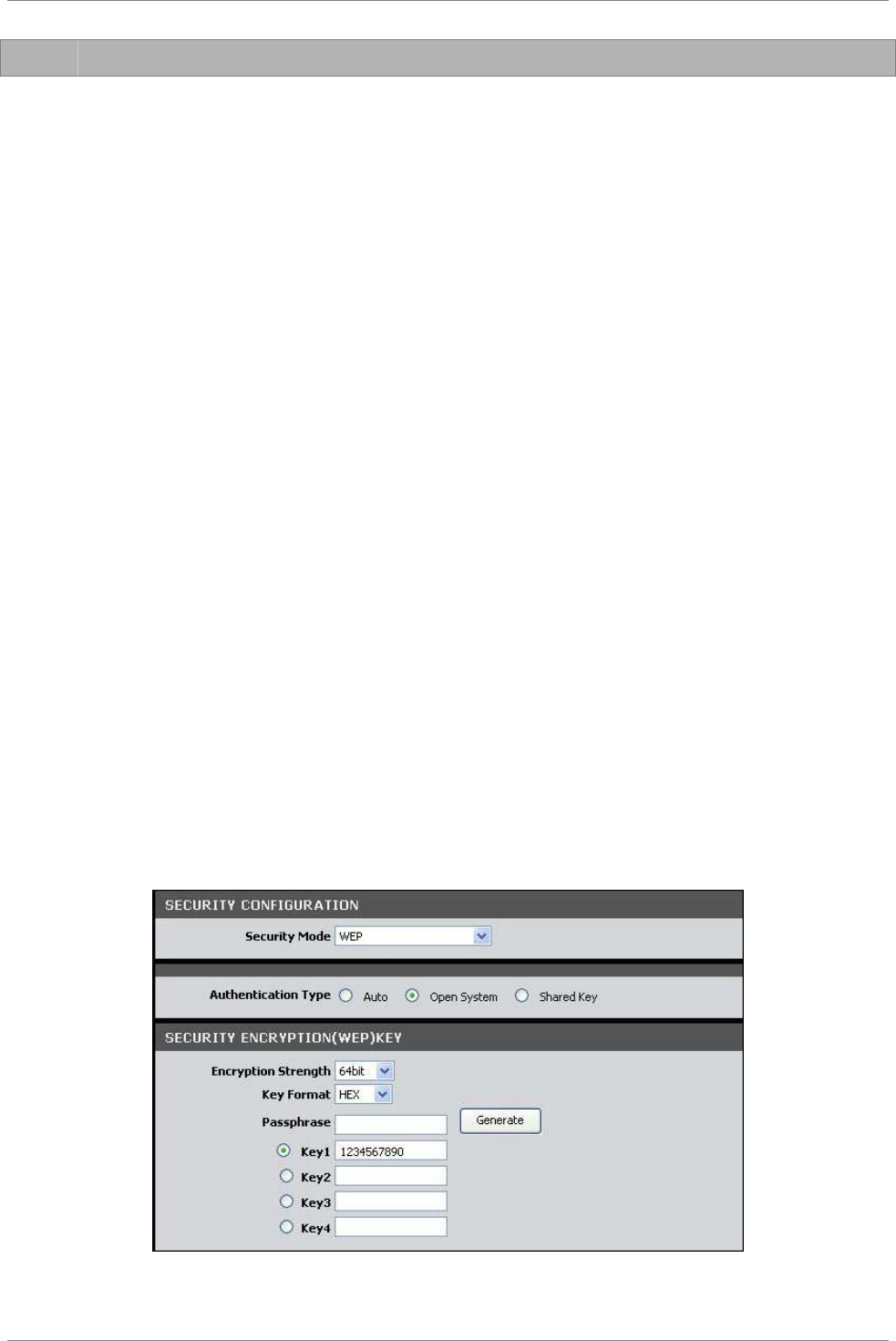
Security Setting
It is strongly recommended to enable the security settings to
secure your network from unauthorized access. Use the Security
Setting page to configure the type of security and encryption of
your wireless network.
To access the Security Setting page, click SETUP > Wireless
Settings > Security Setting or click the Security Setting button.
Name (SSID) — Select the wireless network to configure from the
drop-down list.
Security Mode — Select the security and the encryption type to use.
Select None if you do not want to use any security mode.
WEP
WEP (Wired Equivalent Policy) is the basic security method. With
WEP security, all wireless devices must enter the same key to
connect to the network.
Authentication Type — Select an authentication type. Options are:
Setup
TRENDnet DSLR-2001N 38
•
Auto: Select Auto if you are unsure which authentication is
suitable for your wireless devices.
•
Open System — Open System allows public access to the Modem
Router via wireless communications.
•
Shared Key — Requires users to enter the same WEP key to
exchange data with other wireless devices.
Encryption Strength — Select 64bit to enter or generate a 10-
character key or select 128bit to enter or generate a 26-character
key.
Key Format — Select HEX to generate hexadecimal characters only or
ASCII to generate ASCII characters.
Passphrase — Enter a passphrase, then click the Generate button to
automatically generate WEP keys.
Key 1, 2, 3, 4 — When you enter a passphrase and click the
Generate button, these fields display the auto-generated keys.
Otherwise, enter the WEP key(s) manually.
Click the Apply button to save your changes or click the Cancel
button to discard your changes.
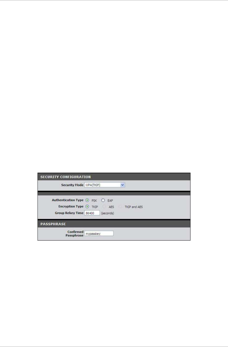
WPA (TKIP)
Select WPA (Wi-Fi Protected Access) using TKIP (Temporal Key
Integrity Protocol) for better encryption.
Authentication Type — Select an authentication type. Options are:
•
PSK: Select to use a passphrase for authentication.
If you select PSK, enter a passphrase in the Confirmed
Passphrase field.
•
EAP — Select to use Extensible Authentication Protocol
(EAP). This should only be used when a Radius server is
connected to your Modem Router.
If you select EAP, enter the following information:
•
Radius Server IP: The IP address of the authentication
server.
•
Radius Server Port: The port number used to connect to
the authentication server.

Setup
TRENDnet DSLR-2001N 39
•
Radius Server Key: Enter the passphrase that matches the
authentication server.
Encryption Type — Displays the encryption type you selected.
Group Rekey Time — Enter the number of seconds to elapse until the
Modem Router prompts for the key again.
Click the Apply button to save your changes or click the Cancel
button to discard your changes.
Setup
TRENDnet DSLR-2001N 40
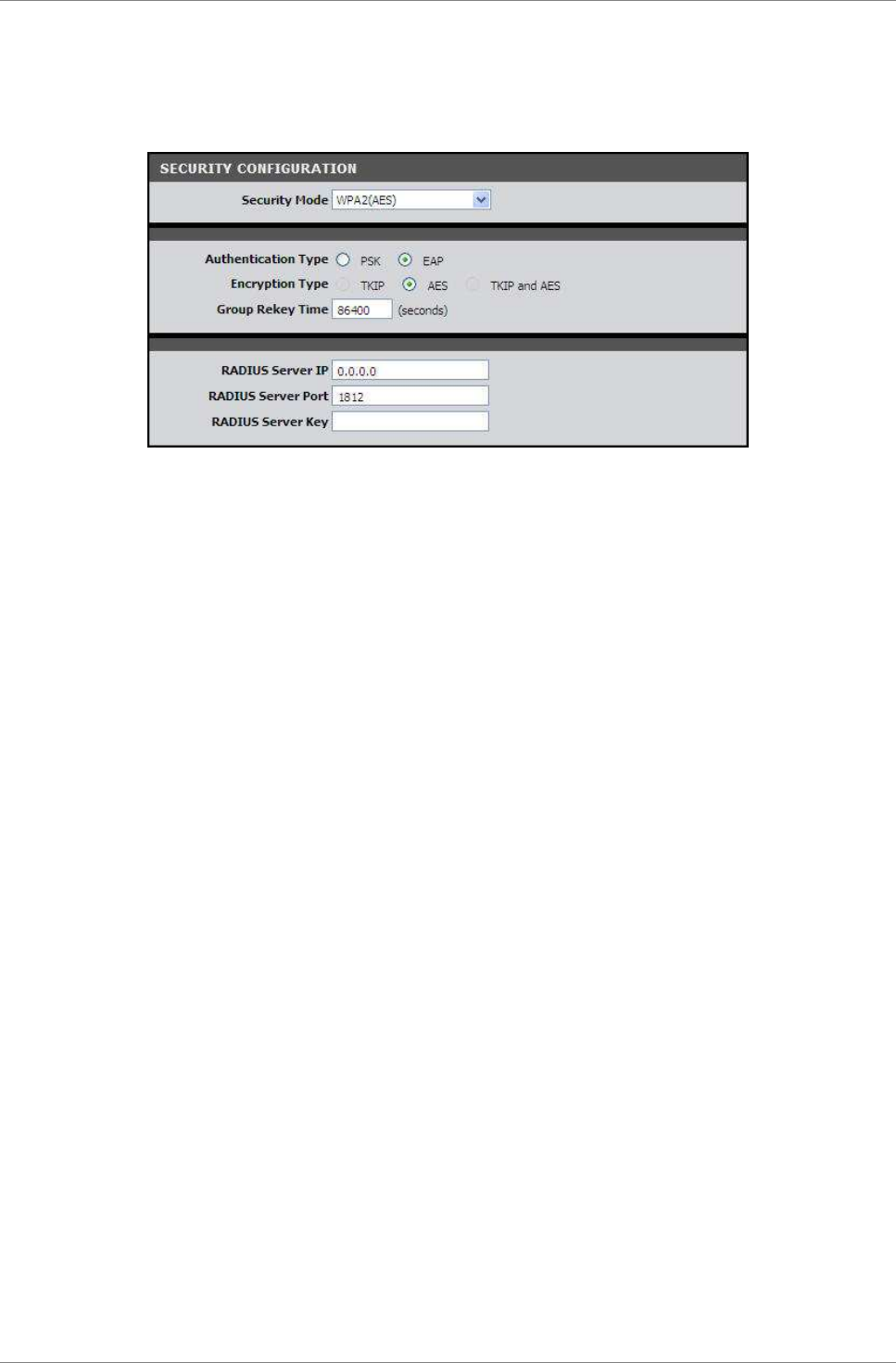
WPA2 (AES)
Select WPA (Wi-Fi Protected Access) using AES (Advanced Encryption
Standard) for better encryption.
Authentication Type — Select an authentication type. Options are:
•
PSK: Select to use a passphrase for authentication.
If you select PSK, enter a passphrase in the Confirmed
Passphrase field.
•
EAP — Select to use Extensible Authentication Protocol
(EAP). This should only be used when a Radius server is
connected to your Modem Router.
If you select EAP, enter the following information:
•
Radius Server IP: The IP address of the authentication
server.
•
Radius Server Port: The port number used to connect to
the authentication server.
•
Radius Server Key: Enter the passphrase that matches the
authentication server.
Encryption Type — Displays the encryption type you selected.
Group Rekey Time — Enter the number of seconds to elapse until the
Modem Router prompts for the key again.
Click the Apply button to save your changes or click the Cancel
button to discard your changes.
WPA (TKIP) / WPA2 (AES)
Select this security mode if you are unsure which mode is suitable
for your wireless devices.
Authentication Type — Select an authentication type. Options are:
•
PSK: Select to use a passphrase for authentication.
If you select PSK, enter a passphrase in the Confirmed
Passphrase field.
Setup
TRENDnet DSLR-2001N 41
•
EAP: Select to use Extensible Authentication Protocol (EAP).
This should only be used when a Radius server is connected
to your Modem Router.
If you select EAP, enter the following information:
•
Radius Server IP: The IP address of the authentication
server.
•
Radius Server Port: The port number used to connect to
the authentication server.
•
Radius Server Key: Enter the passphrase that matches the
authentication server.
Encryption Type — Displays the encryption type you selected.
Group Rekey Time — Enter the number of seconds to elapse until the
Modem Router requires the wireless devices to re-authenticate.
Click the Apply button to save your changes or click the Cancel
button to discard your changes.
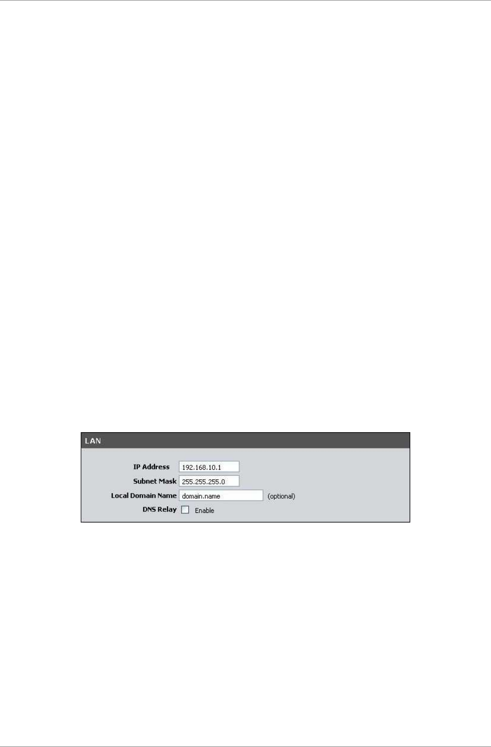
5.3 Local Network
To access the Local Network page, click SETUP > Local Network.
LAN
This section contains the local settings of your network. These
settings are private to your internal network and cannot be seen
on the Internet. It is recommended to keep the default values.
IP Address — The default value is 192.168.10.1.
Subnet Mask — The default value is 255.255.255.0.
Local Domain Name — Enter a name to refer to the group of devices
that will be assigned addresses from this pool.
DNS Relay — Select whether to enable or disable the DNS relay
function. Check this box to request automatic assignment of a DNS,
then enter the Primary DNS Server and the Secondary DNS Server in
the DHCP Setting screen below.
Setup
TRENDnet DSLR-2001N 42
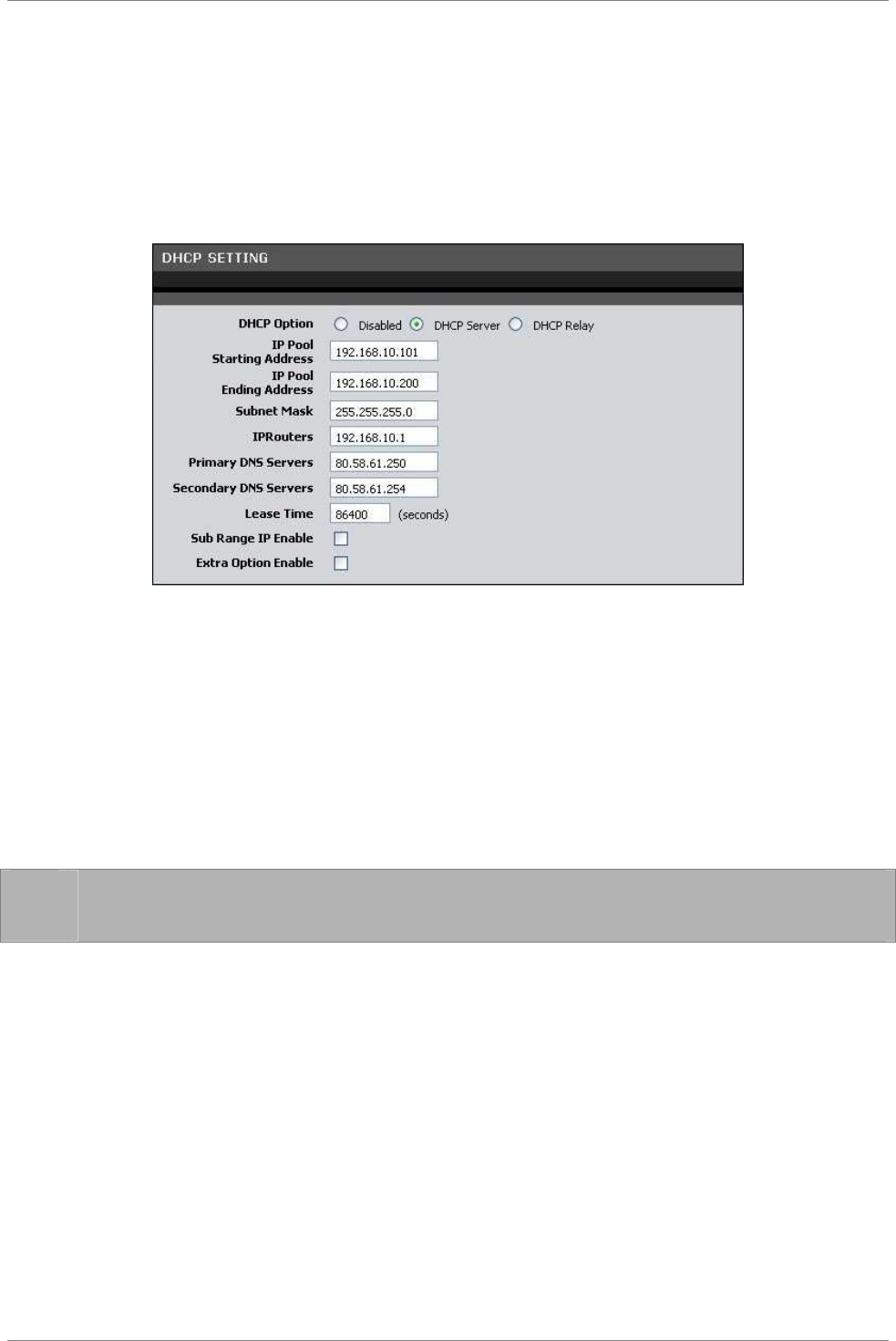
DHCP Setting
This section allows you to configure your Modem Router to use the
Dynamic Host Configuration Protocol (DHCP). You can set your Modem
Router as a DHCP server or a DHCP relay agent of your network.
The information required on the DHCP Setting screen vary depending
on the selected DHCP option.
DHCP Option — Select the DHCP mode of your Modem Router. Options
are:
•
Disabled: Select this setting if there is already a DHCP
server on your network and all devices on your network are
using static IP addresses.
•
DHCP Server: By default, your Modem Router is set as a DHCP
server. See more details below.
•
DHCP Relay: Select this setting to set your Modem Router as
a DHCP Relay agent. See description on the next page.
☞
NOTE: If you want to set your Modem Router as a DHCP server,
make sure there is no other DHCP server on your network.
DHCP Server
If you set your Modem Router as the DHCP server, your Modem Router
will automatically assign an IP address to each computer on your
network. By default, the fields for DHCP settings have predefined
values. It is recommended to retain these values unless specified
by your ISP.
IP Pool Starting Address — Enter the lowest range of IP address to
assign. The default value is 192.168.10.101.
IP Pool Ending Address — Enter the highest range of IP address to
assign. The default value is 192.168.10.200.
Subnet Mask — Enter the subnet mask. The default value is
255.255.255.0.

Setup
TRENDnet DSLR-2001N 43
IPRouters — Enter the IP address of your Modem Router. The default
value is 192.168.10.1.
Primary DNS Server and Secondary DNS Server — Enter a primary and
a secondary DNS server if the DNS Relay option is enabled.
Lease Time — Enter the lease time in seconds. The lease time is
the amount of time a device is allowed connection to your Modem
Router using its current dynamic IP address. At the end of the
lease time, the lease is either renewed or a new IP address is
assigned. The default value is 86400 seconds (1 day).
Sub Range IP Enable — Check this box to set another range of IP
address.
•
Vendor Class (Option 60): Enter a vendor class name.
•
Sub-String Match: Check to enable the sub-string match
function.
•
IP Pool Starting Address — Enter the lowest sub range of IP
address to assign.
•
IP Pool Ending Address — Enter the highest sub range of IP
address to assign.
•
Subnet Mask — Enter the subnet mask.
•
IPRouters — Enter the IP address of your Modem Router.
•
Primary DNS Server and Secondary DNS Server — Enter a
primary and a secondary DNS server of the sub range.
Extra Option Enable — Check this box to enable extra options.
•
Option 240, Option 241, Option 242, Option 244, and Option
245: Enter a name for the corresponding option.
Click the Apply button to save your changes or click the Cancel
button to discard your changes.
DHCP Relay
Some ISPs function as the DHCP server for their clients’ small
office network. In this case, you can set your Modem Router to act
as a DHCP relay agent. When a device on your network requests
Internet access, your Modem Router contacts the ISP to obtain the
IP configuration, and then forwards the information to that device.
DHCP Server IP — Enter the IP address of the DHCP server.
Click the Apply button to save your changes or click the Cancel
button to discard your changes.
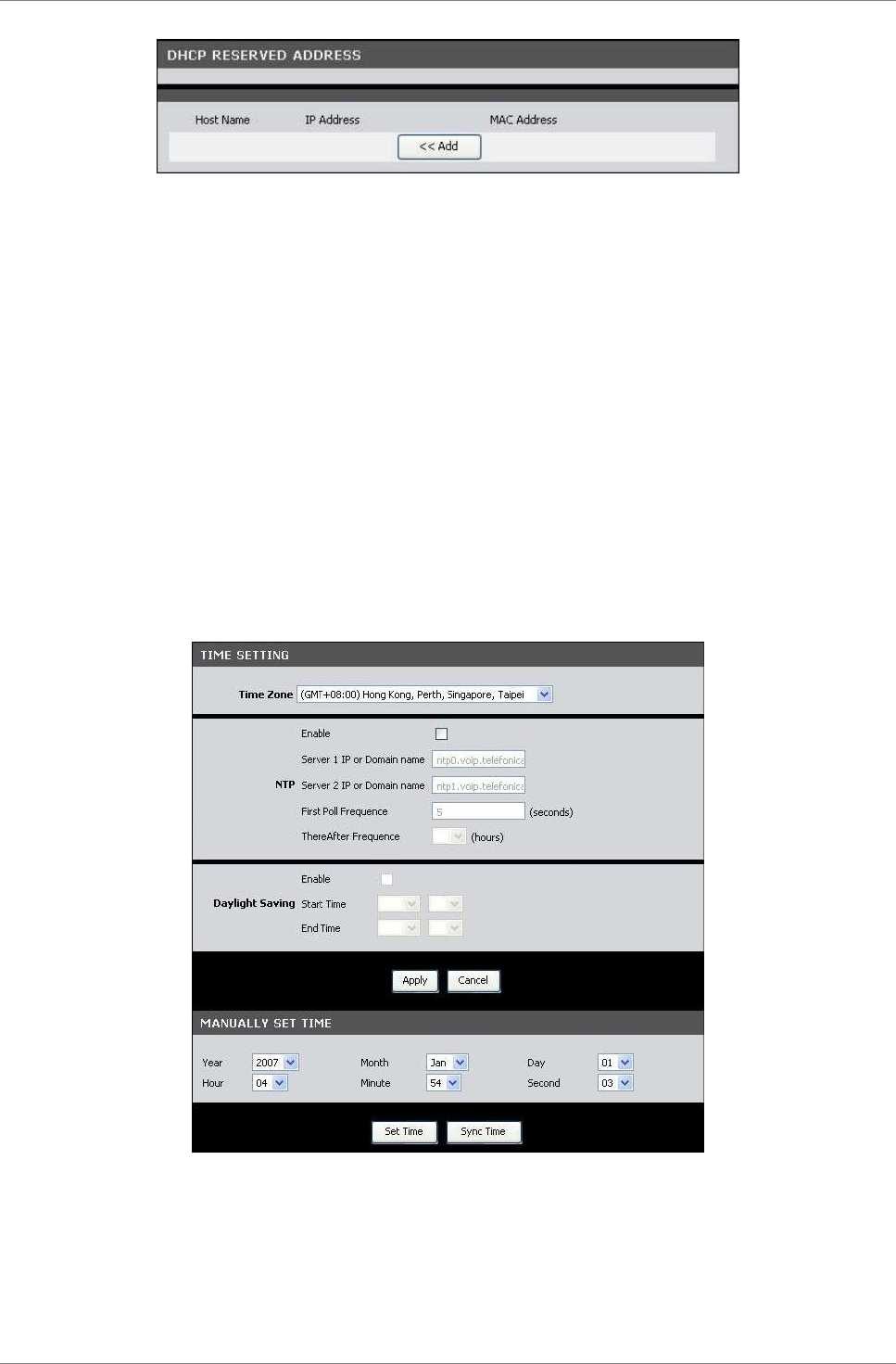
DHCP Reserved Address
This section lists the DHCP reserved addresses on your network. If
your Modem Router is set as the DHCP server, your Modem Router can
reserve a particular IP address to a specific device. To reserve
an IP address, click the Add button.
Setup
TRENDnet DSLR-2001N 44
Enable — Check this box to enable this function.
Host Name — Enter a host name for the DHCP reserved address.
IP Address — Enter the IP address to reserve.
MAC Address — Enter the MAC address of the device to reserve the
IP address to.
Click the Apply button to save your changes or click the Cancel
button to discard your changes.
5.4 Time and Date
The Time and Date page allows you to manually configure the time
and date of your network or to synchronize with a Network Time
Protocol (NTP) server.
To access the Time and Date page, click SETUP > Time and Date.
Time Zone — Select the time zone in your location. To set the
network time and date according to the selected time zone, click
the Sync Time button.
NTP (Network Time Protocol) — Check the Enable box to synchronize
the network time and date with an NTP server.

Setup
TRENDnet DSLR-2001N 45
•
Server 1 IP or Domain name: Enter the IP address or the
domain name of the NTP server to synchronize your network
with.
•
Server 2 IP or Domain name: Enter the IP address or the
domain name of another NTP server to synchronize your
network with in case Server 1 is not available.
•
First Poll Frequency: Enter the number in seconds of the
first poll.
•
ThereAfter Frequency: Select the succeeding frequency from
the drop-down list.
Daylight Saving — Check the Enable box to enable daylight saving
time.
•
Start Time: Select the month and the day to start the
daylight saving time.
•
End Time: Select the month and the day to end the daylight
saving time.
Click the Apply button to save your changes or click the Cancel
button to discard your changes.
To manually set the time and date of your network, select the Year,
Month, Day, Hour, Minute, and Second from their corresponding
drop-down lists. Click the Set Time button to apply the changes.
Advanced
TRENDnet DSLR-2001N 46
Chapter 6: Advanced
The Advanced menu configurations greatly affect the operating
performance of your Modem Router. This menu is intended for
advance users. It is recommended to retain the default settings if
you are unsure about them.
6.1 Advanced Wireless
Wireless Router Settings
This page allows you to configure advanced wireless router
settings.
Click Advanced > Advanced Wireless > Advanced Wireless or click
the Advanced Setting button.
SSID Advertise —Check this box to allow wireless devices scanning
the area for wireless networks to detect your Modem Router.
Transmit Power — Select the output power of the wireless LAN.
WMM (Wi-Fi Multimedia) — Select whether to enable or disable WMM.
The WMM feature enhances the Quality of Service (QoS) of a network
that is used by multimedia applications such as Voice-over-IP
(VoIP) and video. If WMM is enabled, multimedia applications on
your network have priority over regular data packets, allowing
multimedia applications to run smoother and with fewer errors.
WMM APSD — If WMM is enabled, you can also select whether to
enable or disable WMM APSD (Automatic Power Save Delivery). APSD
manages radio usage for battery-powered devices to allow longer
battery life in certain conditions.
Fragment Threshold — Fragment threshold refers to the maximum size
of a packet before data is fragmented into multiple packets. The
Advanced
TRENDnet DSLR-2001N 47
default and recommended value is 2346 bytes. If you experience a
high packet error rate, you may slightly adjust the value. Setting
the fragment threshold too low may result in poor network
performance.
RTS Threshold — The default and recommended value is 2347. Should
you encounter inconsistent data flow, only slight modifications
should be made.
Beacon Interval — Enter a value in milliseconds. A beacon is a
packet that is sent out by the Modem Router to synchronize the
wireless network. The beacon interval value indicates the
frequency interval of the beacon. The default value is 100.
Click the Apply button to save your changes or click the Cancel
button to discard your changes.
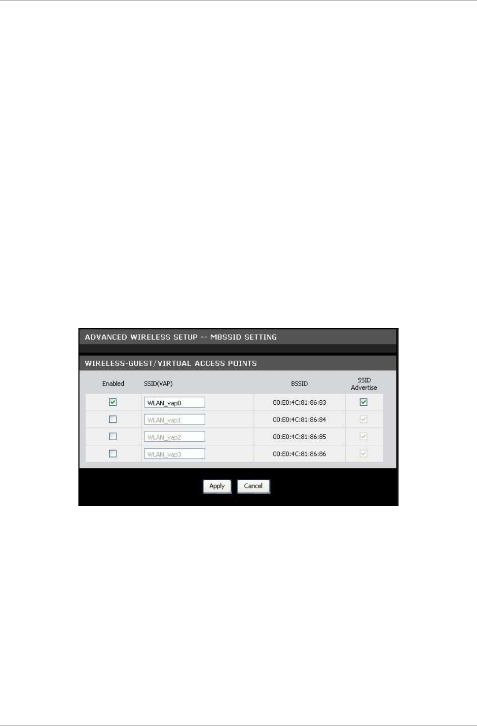
MBSSID Settings
This page allows you to configure up to four virtual access points
(VAP).
Click Advanced > Advanced Wireless > MBSSID Setting or click the
MBSSID Setting button.
Check the Enabled box of the VAP to enable it. If you enable a VAP,
you can modify its SSID and check its SSID Advertise box to allow
wireless devices scanning for a wireless network to detect the VAP.
Click the Apply button to save your changes or click the Cancel
button to discard your changes.
Advanced
TRENDnet DSLR-2001N 48
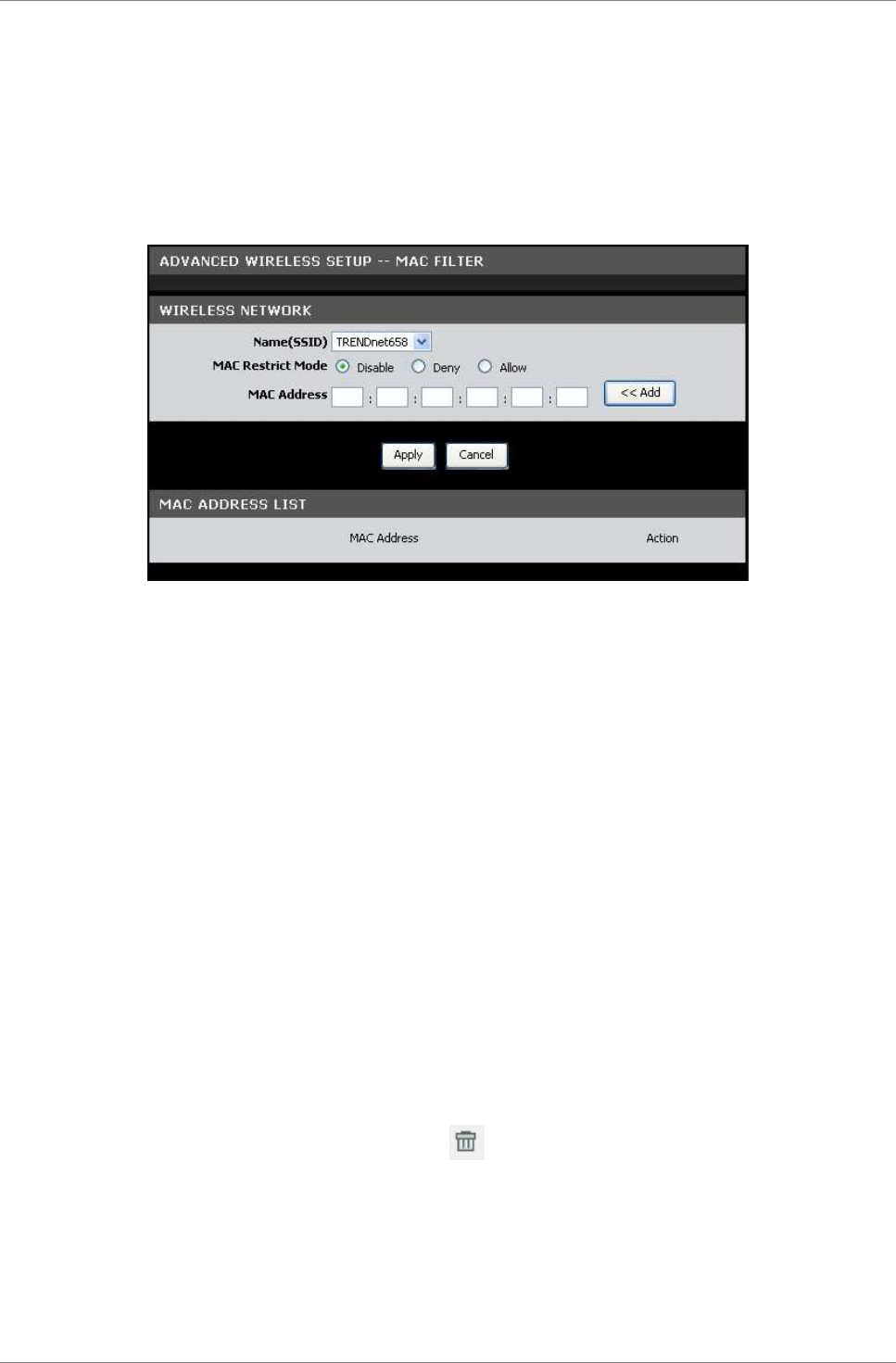
Wireless MAC Filter
This page allows you to deny or allow devices to access the
wireless network by filtering their MAC addresses.
Click Advanced > Advanced Wireless > Wireless MAC Filter or click
the MAC Filter button.
Name (SSID) — Select the SSID from the drop-down list.
To Set MAC Filter
Do the following to deny or allow a device to access to the
wireless network.
1. Select the MAC Restrict Mode. Options are:
•
Disable: No restriction.
•
Deny: To deny access to the wireless network.
•
Allow: To allow access to the wireless network.
2. On the MAC Address field, enter the MAC address of the device
that you want to deny or allow access.
3. Click the Add button to add the MAC address to the MAC
ADDRESS LIST.
4. Click the Apply button to apply the MAC filter or click the
Cancel button to discard your changes.
To Remove MAC Filter
1. On the MAC ADDRESS LIST, click the icon to remove the
restriction on the corresponding MAC filter.
2. When prompted, click OK to confirm.
Advanced
TRENDnet DSLR-2001N 49
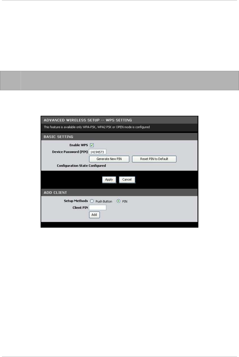
WPS Setting
Wi-Fi Protected Setup (WPS) is designed to make wireless setup
easy and yet secure. Users do not need to know the network SSID
and passphrases to use WPS to join the wireless network.
This page allows you to enable WPS-supported devices to connect to
your Modem Router.
☞
NOTE: This feature is available only in WPA-PSK, WPA2PSK, or
OPEN mode.
Click Advanced > Advanced Wireless > WPS Setting or click the WPS
Setting button.
Basic Setting
Enable WPS — Check this box to enable the WPS function.
Device Password (PIN) — Displays the PIN password. To generate a
new PIN, click the Generate New PIN button. To reset the PIN to
default, click the Reset PIN to Default button.
Click the Apply button to save your changes or click the Cancel
button to discard your changes.
Add Client
Setup Methods — Select one of the following:
•
Push Button: Select to connect WPS-supported devices with a
push of a button.
•
PIN: Select to prompt WPS-supported devices to enter the
PIN before allowing access to the wireless network.
Advanced
TRENDnet DSLR-2001N 50
•
Client PIN: Enter the WPS-supported device’s PIN. This
PIN is used to connect to your Modem Router. Click the
Add button to apply the configuration.
6.2 Multi-WAN
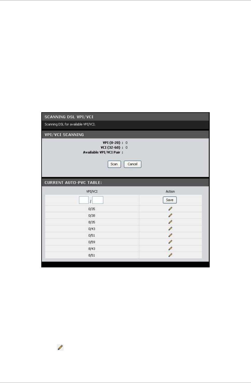
DSL Auto Scan
This page allows you to scan your DSL line for available VPI/VCI.
To access the DSL Auto Scan page, click Advanced > Multi-WAN > DSL
Auto Scan or click the DSL Auto Scan button.
VPI/VCI Scanning
Click the Scan button to start scanning your DSL line for
available VPI/VCI. Scanning may take several minutes. Click the
Cancel button to stop scanning.
Current Auto-PVC Table
Displays the current PVCs. Your Modem Router supports up to 8 PVCs.
To modify an entry, do the following:
1. Click the icon. The selected entry is displayed on the
editable field.
2. Enter the new VPI/VCI values.
3. Click the Save button.
Advanced
TRENDnet DSLR-2001N 51
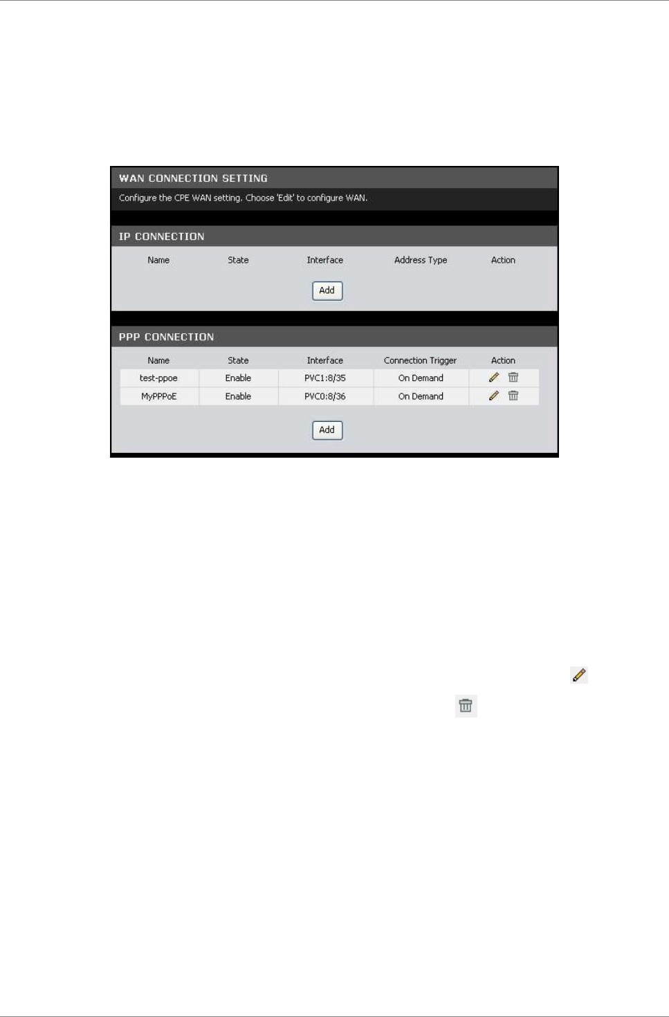
IP/PPP Config
This page allows you to create multiple Wide Are Networks (WAN)
and manually add an IP or a PPP connection.
To access the IP/PPP Config page, click Advanced > Multi-WAN >
IP/PPP Config or click the WAN Config button.
To add an IP or PPP connection, do the following:
1. Click the Add button of the connection that you want to add.
2. On the Interface field, select the PVC.
3. Enter the connection settings. The screen and the required
settings vary depending on the type of connection that you
want to add. See “Protocol” on page 26 for more information.
4. Click the Apply button to save your changes or click the
Cancel button to discard your changes.
To edit an IP or PPP connection, click the corresponding icon.
To delete an IP or PPP connection, click the corresponding
icon.
Default Route
This page allows you to change the default route of your Modem
Router.
To access the Default Route page, click Advanced > Multi-WAN >
Default Route or click the Default Route button.
Change Default Route — Select the connection to set as the default
route from the drop-down list.
Click the Apply button to save your changes or click the Cancel
button to discard your changes.
Advanced
TRENDnet DSLR-2001N 52
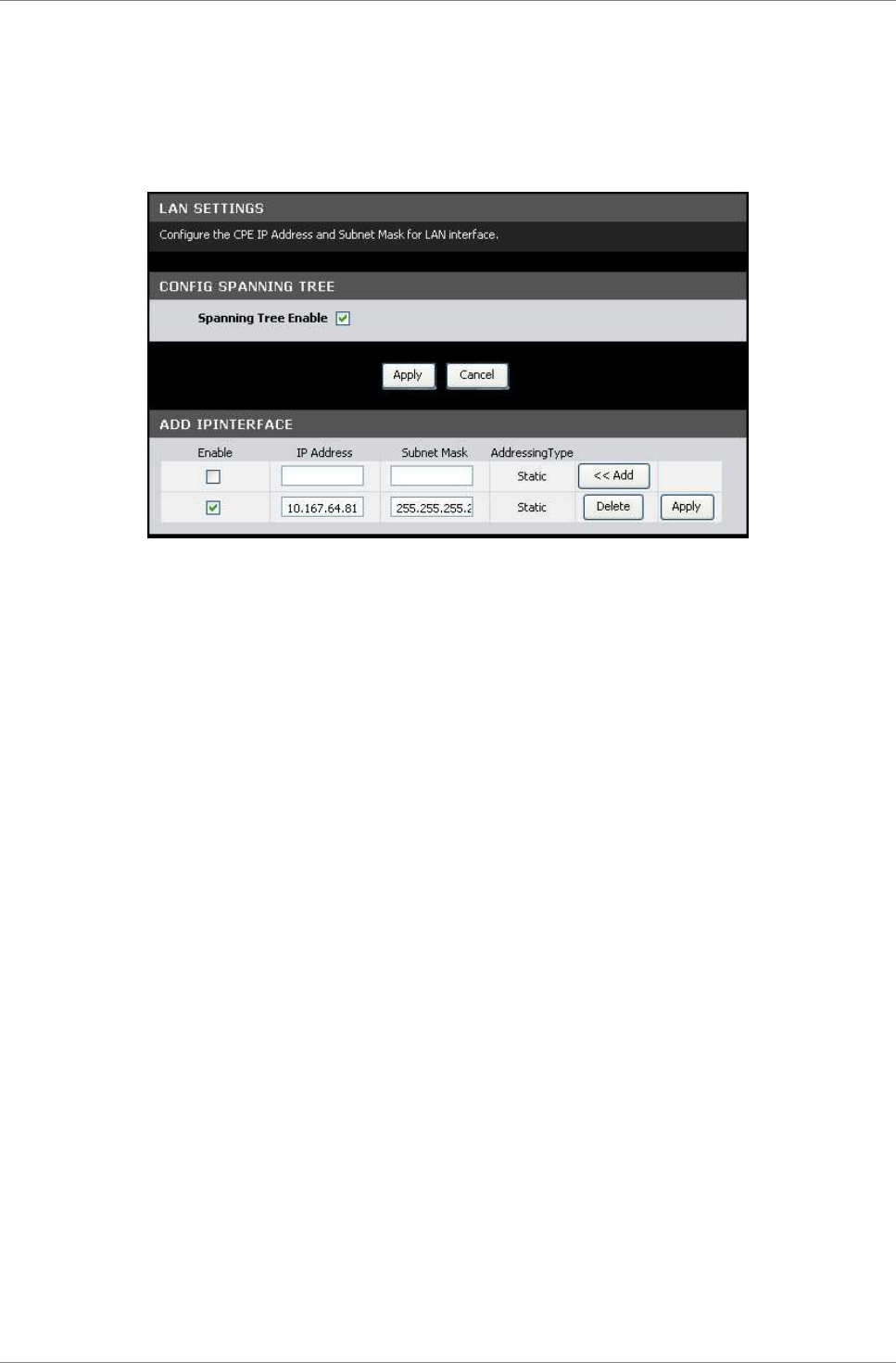
6.3 Advanced-LAN
This page allows you to add multiple LAN IP addresses.
To access the Advanced-LAN page, click Advanced > Advanced-LAN.
Config Spanning Tree
Spanning Tree Enable — Check this box to enable spanning tree.
Click the Apply button to save your changes or click the Cancel
button to discard your changes.
Add IP Interface
To add an IP interface, do the following:
1. On the first record on the table, enter the IP Address and
Subnet Mask.
2. Check the Enable box to enable the IP interface.
3. Click the Add button. The new entry is listed on the bottom
of the list.
To apply the IP interface, click the corresponding Apply button.
To delete the IP interface, click the corresponding Delete button.
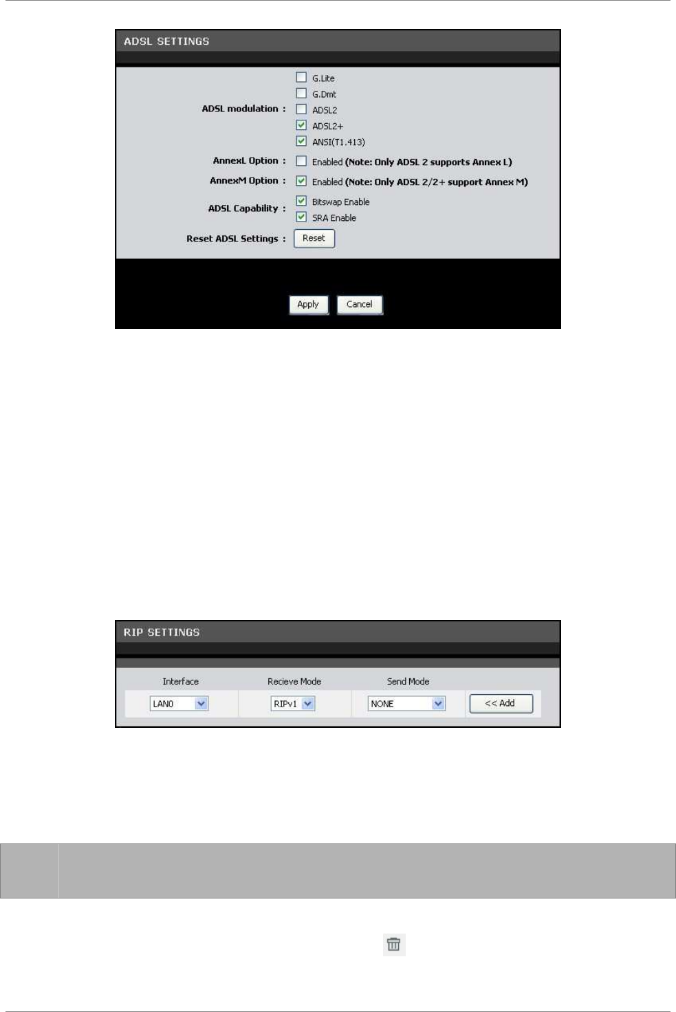
6.4 ADSL Settings
This page allows you to select ADSL modulations, capabilities, and
other options. Consult your ISP to determine the appropriate
settings.
To access the ADSL Settings page, click Advanced > ADSL Settings.
Advanced
TRENDnet DSLR-2001N 53
Check a corresponding box to select the option.
To reset the ADSL settings, click the Reset button.
Click the Apply button to save your changes or click the Cancel
button to discard your changes.
6.5 RIP Settings
A Routing Information Protocol (RIP) is an Internet protocol that
is used to share routing information table with other routing
devices on the local and wide area network.
To access the RIP Settings page, click Advanced > RIP Settings.
To add RIP settings, do the following:
1. Select the Interface.
2. On the Receive Mode and Send Mode drop-down lists, select the
appropriate versions.
☞
NOTE: The selected versions should match the versions
supported by the other routers on your network.
3. Click the Add button.
To delete an RIP setting, click the corresponding button.
Advanced
TRENDnet DSLR-2001N 54
6.6 NAT
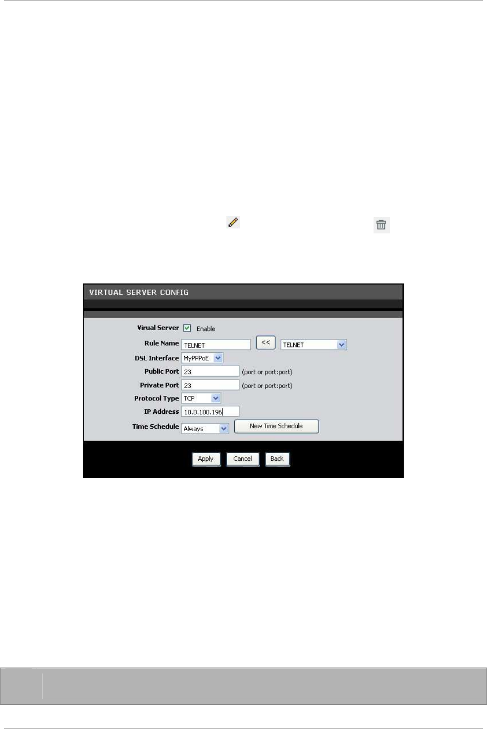
Virtual Server
A virtual server allows remote devices accessing the Web or FTP
services via a public IP address be redirected to local servers in
the LAN. Depending on the requested service (TCP/UDP port number),
your Modem Router redirects the external service request to the
appropriate server in the LAN.
To access the Virtual Server page, click Advanced > NAT > Virtual
Server or click the Virtual Server button.
The table displays the virtual servers on your network. To edit an
entry, click the corresponding icon. To delete an entry, click
the corresponding button.
To add virtual servers, click the Add button. The Virtual Server
Config screen is displayed.
Virtual Server — Check this box to enable the virtual server
function.
Rule Name — Enter a rule name or select an application name from
the drop-down list on the right, then click the << button. If you
select a predefined application name, the Public Port, Private
Port, and Protocol Type are automatically configured.
DSL Interface — Select a DSL interface from the drop-down list.
Public Port — Enter the public port. This is the port seen from
the WAN side.
Private Port — Enter the private port. This is the port being used
by applications within your local network.
☞
NOTE: The public and private ports are usually the same.
Protocol Type — Select the protocol from the drop-down list.
Advanced
TRENDnet DSLR-2001N 55
IP Address — Enter the local network IP address of the system
hosting the server.
Time Schedule — Select a schedule when to use the virtual server
or click the New Time Schedule button to create a new schedule.
Click the Apply button to save your changes or click the Cancel
button to discard your changes.
Port Trigger
This page displays the port trigger settings on your network. Port
triggering is a type of port forwarding where outgoing data from
specific ports are sent to specific incoming ports.
To access the Port Trigger page, click Advanced > NAT > Port
Trigger or click the Port Trigger button.
The table displays the port triggers on your network. To edit an
entry, click the corresponding icon. To delete an entry, click
the corresponding button.
To add port triggers, click the Add button. The Port Trigger
Config screen is displayed.
Port Trigger — Check this box to enable port triggering.
Rule Name — Enter a rule name.
Use Interface — Select a DSL interface from the drop-down list.
Trigger Port — Enter the port that will trigger the device to open
ports for incoming data.
Trigger Port Protocol — Select the trigger port protocol from the
drop-down list.
Public Port — Enter the public port to be opened.
Public Port Protocol — Select the public port protocol.
Time Schedule — Select a schedule to apply port triggering from
the drop-down list or click the New Time Schedule button to create
a new schedule.
Advanced
TRENDnet DSLR-2001N 56
Click the Apply button to save your changes or click the Cancel
button to discard your changes.
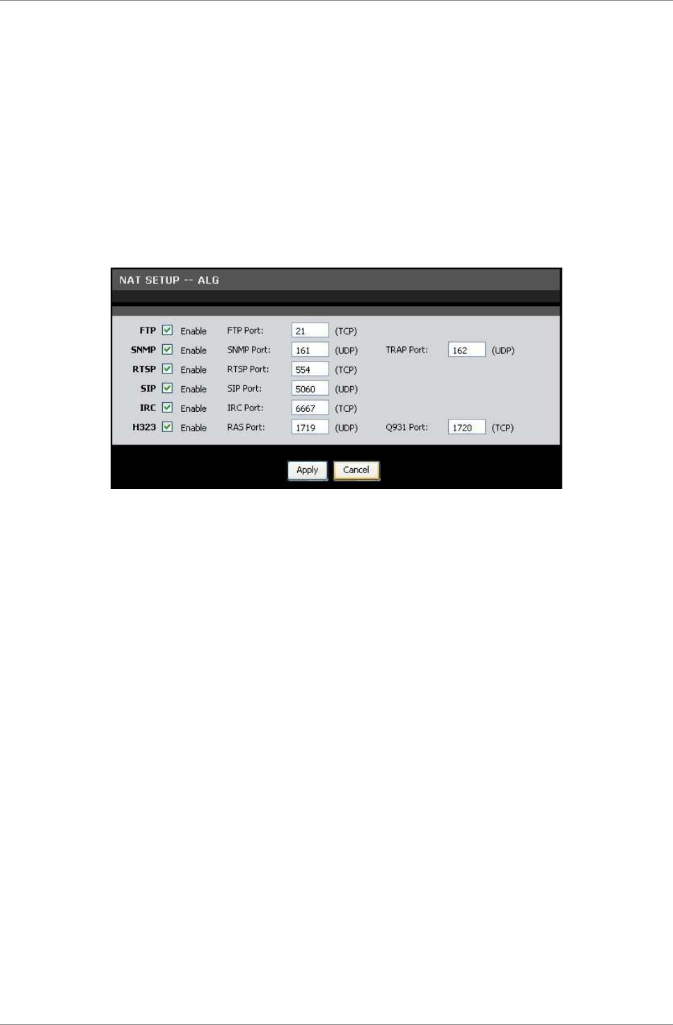
ALG
Application Layer Gateway (ALG) consists of a security component
that augments NAT or a firewall. Your Modem Router allows NATs to
support address and port translation for certain application layer
protocols such as FTP, SNMP, and others.
To access the ALG page, click Advanced > NAT > ALG or click the
ALG Setting button.
FTP — File Transfer Protocol (FTP) is used to transfer files
between computers on a TCP/IP based network, such as the Internet.
Check this box to enable this function to work through your Modem
Router.
SNMP — Simple Network Management Protocol (SNMP) is a network
protocol used to monitor the devices connected to a network. Check
this box to enable this function to work through your Modem Router.
RTSP — Real Time Streaming Protocol (RTSP) is a network protocol
used for entertainment and communication systems to control
streaming media sessions. Check this box to enable this function
to work through your Modem Router.
SIP — Session Initiation Protocol (SIP) is a signaling protocol
used to control multimedia communication sessions such as voice
and video calls over Internet Protocol (IP). Check this box to
enable this function to work through your Modem Router.
IRC — Internet Relay Chat (IRC) is a real-time Internet chatting
protocol designed for group communications. Check this box to
enable this function to work through your Modem Router.
H323 — H.323 is a standard that provides audio-visual
communication sessions on a network. It is widely implemented in
voice and video conferencing equipments and is used within various
Internet real-time applications such as NetMeeting. Check this box
to enable this function to work through your Modem Router.
It is recommended to retain the default ports of these protocols.

Advanced
TRENDnet DSLR-2001N 57
Click the Apply button to save your changes or click the Cancel
button to discard your changes.
Advanced
TRENDnet DSLR-2001N 58
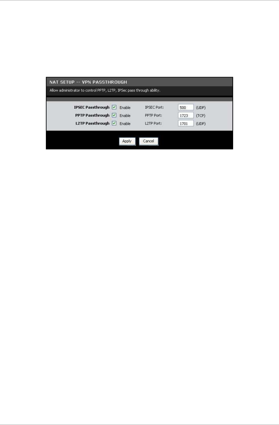
VPN Passthrough
This page allows you to control VPN tunnels using IPSEC, PPTP, and
L2TP protocols to pass through your Modem Router.
To access the VPN Passthrough page, click Advanced > NAT > VPN
Passthrough or click the VPN Setting button.
IPSEC Passthrough — Internet Protocol Security (IPSec) is a
protocol suite used to secure IP communications by authenticating
and encrypting IP packets. Check this box to enable this function
to work through your Modem Router.
PPTP Passthrough — Point-to-Point Tunneling Protocol (PPTP) allows
Point-to-Point protocol (PPP) to be tunneled through a network.
Check this box to enable this function to work through your Modem
Router.
L2TP Passthrough — Layer 2 Tunneling Protocol (L2TP) is an
extension to the PPP protocol that enables ISPs to operate VPNs.
Check this box to enable this function to work through your Modem
Router.
It is recommended to retain the default ports of these protocols.
Click the Apply button to save your changes or click the Cancel
button to discard your changes.
Advanced
TRENDnet DSLR-2001N 59
6.7 Firewall
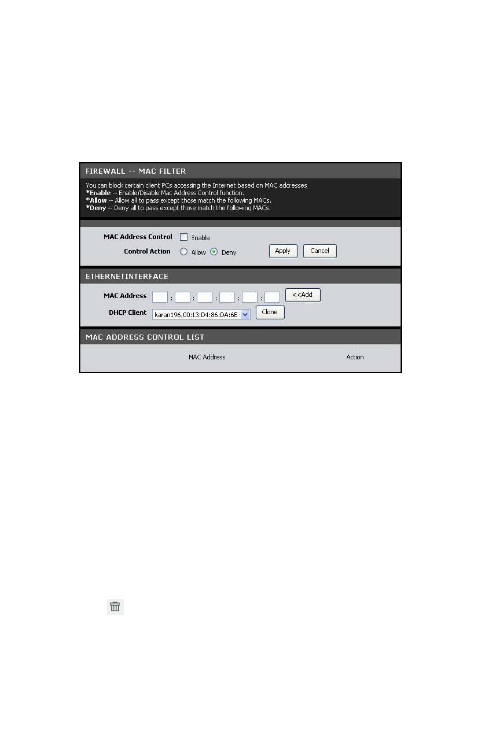
MAC Filter
This page allows you to set up a list of MAC addresses which will
be allowed or restricted to access the Internet.
To access the MAC Filter page, click ADVANCED > Firewall > MAC
Filter or click the MAC Filter button.
MAC Address Control — Check this box to enable the MAC filter
function.
Control Action — Select Allow to allow a specified MAC address to
access the Internet or Deny to restrict a specified MAC address
access to the Internet.
Click the Apply button to save and activate the MAC filter or
click the Cancel button to discard your changes.
MAC Address — Enter the MAC address of the device you want to
allow or deny access to the Internet. To use the MAC address of
the DHCP client, click the Clone button. The MAC address is
automatically copied to the MAC address field. Click the Add
button to add the MAC address to the filter list.
The MAC ADDRESS CONTROL LIST displays the MAC address of the
devices that are either allowed or denied access to the Internet.
To remove an entry from the list, click the corresponding
button.
Advanced
TRENDnet DSLR-2001N 60
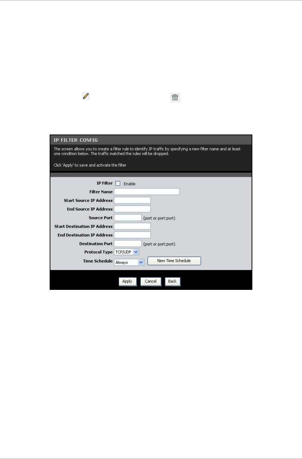
IP Filter
This page allows you to create filter rules to control outgoing
traffic to the Internet based on a range of IP addresses and their
protocols.
To access the IP Filter page, click ADVANCED > Firewall > IP
Filter or click the IP Filter button.
The table lists the existing filter rules. To edit an entry, click
the corresponding icon. To delete an entry, click the
corresponding button.
To add a filter, click the Add button. The IP Filter Config screen
is displayed.
IP Filter — Check this box to enable IP filtering.
Filter Name — Enter a filter rule name.
Start Source IP Address — Enter the starting point of the source
IP address.
End Source IP Address — Enter the ending point of the source IP
address.
Source Port — Enter the source port number.
Start Destination IP Address — Enter the starting point of the
destination IP address.
End Destination IP Address — Enter the ending point of the
destination IP address.
Destination Port — Enter the destination port number.
Protocol Type — Select the protocol from the drop-down list.
Advanced
TRENDnet DSLR-2001N 61
Time Schedule — Select the time to implement the IP filter or
click the New Time Schedule button to create a new schedule.
Click the Apply button to save and activate the filter or click
the Cancel button to discard your changes.
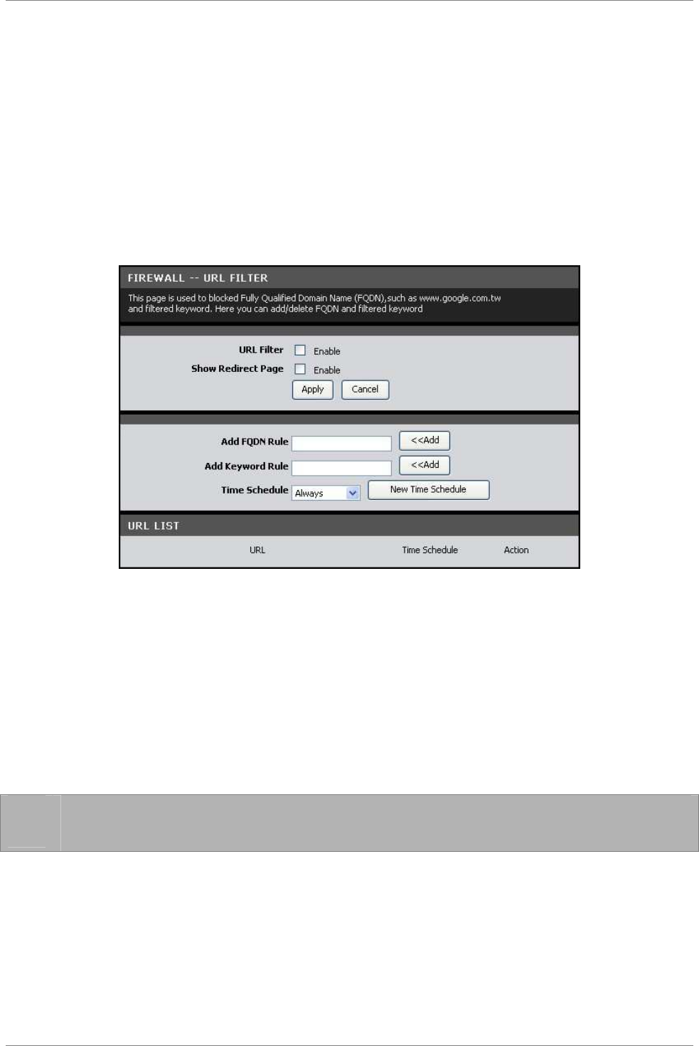
URL Filter
This page allows you to deny network devices to access specific
URLs or URLs that contain specific keywords.
To access the URL Filter page, click ADVANCED > Firewall > URL
Filter or click the URL Filter button.
URL Filter — Check this box to enable URL filtering.
Show Redirect Page — Check this box to redirect devices to another
website when the website they are trying to access is blocked.
Click the Apply button to save and activate the filter or click
the Cancel button to discard your changes.
To Filter a URL
1. On the Add FQDN Rule field, enter a Fully Qualified Domain
Name (FQDN) that you want to block.
☞
NOTE: For example, if you block www.google.com, all websites
with google.com, such as mail.google.com, are also blocked.
2. Select the time to implement the URL filter or click the New
Time Schedule button to create a new schedule.
3. Click the Add button of the Add FQDN Rule. The entry is
listed on the URL LIST table.
To Filter Keyword
Advanced
TRENDnet DSLR-2001N 62
1. On the Add Keyword Rule field, enter a keyword. If a part of
the URL contains this keyword, the website will not be
accessible.
2. Select the time to implement the URL filter or click the New
Time Schedule button to create a new schedule.
3. Click the Add button of the Add Keyword Rule. The entry is
listed on the URL LIST table.
To delete an entry, click the corresponding button.
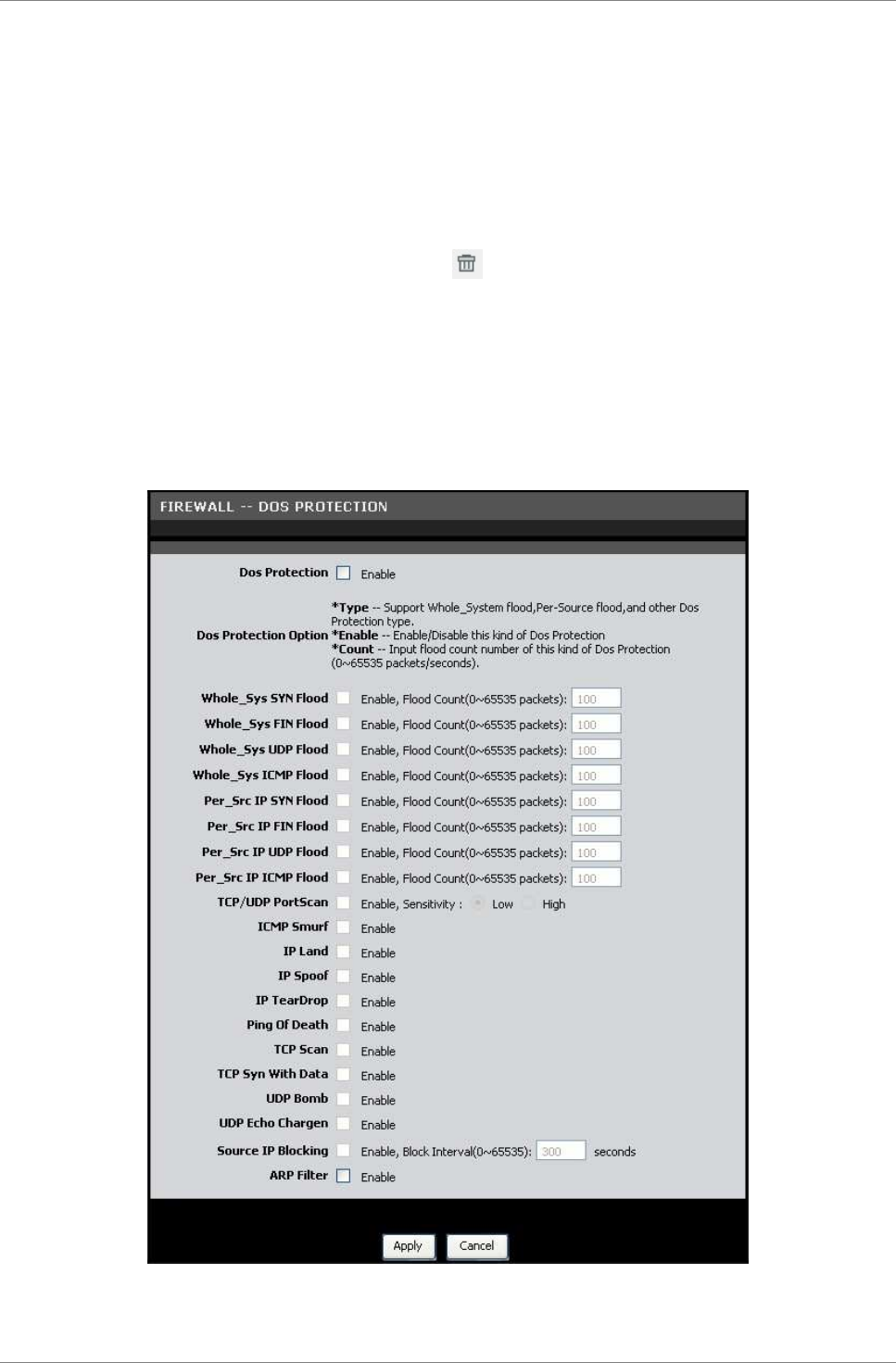
DOS Protection
This page allows you to protect your network from hackers to run
Denial of Service (DoS) attacks.
To access the DOS Protection page, click ADVANCED > Firewall > DOS
Protection or click the DOS Protection button.
Dos Protection — Check this box to enable DoS protection.
Advanced
TRENDnet DSLR-2001N 63
Dos Protection Option — Check the appropriate boxes to enable
protection from SYN flood, FIN flood, UDP flood, ICMP flood, SMURF,
IP spoofing, and others. Enter the flood count numbers or retain
the default values if you are unsure about them.
Check the Apply button to save and activate DoS protection or
click the Cancel button to discard your changes.
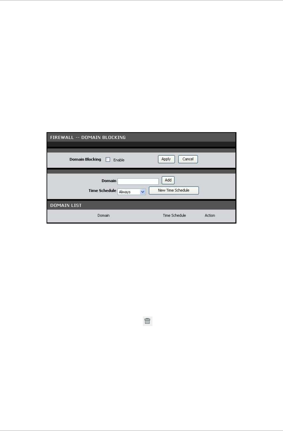
Domain Blocking
This page allows you to deny network devices to access specific
domains such as an http and an ftp.
To access the Domain Blocking page, click ADVANCED > Firewall >
Domain Blocking or click the Domain Blocking button.
Domain Blocking — Check this box to enable domain blocking. Click
the Apply button to activate domain blocking.
To Block Domains
1. On the Domain field, enter the domain name to block.
2. Select the time to implement the domain blocking or click the
New Time Schedule button to create a new schedule.
3. Click the Add button to add the domain. The entry is listed
on the DOMAIN LIST table.
To delete an entry, click the corresponding icon.
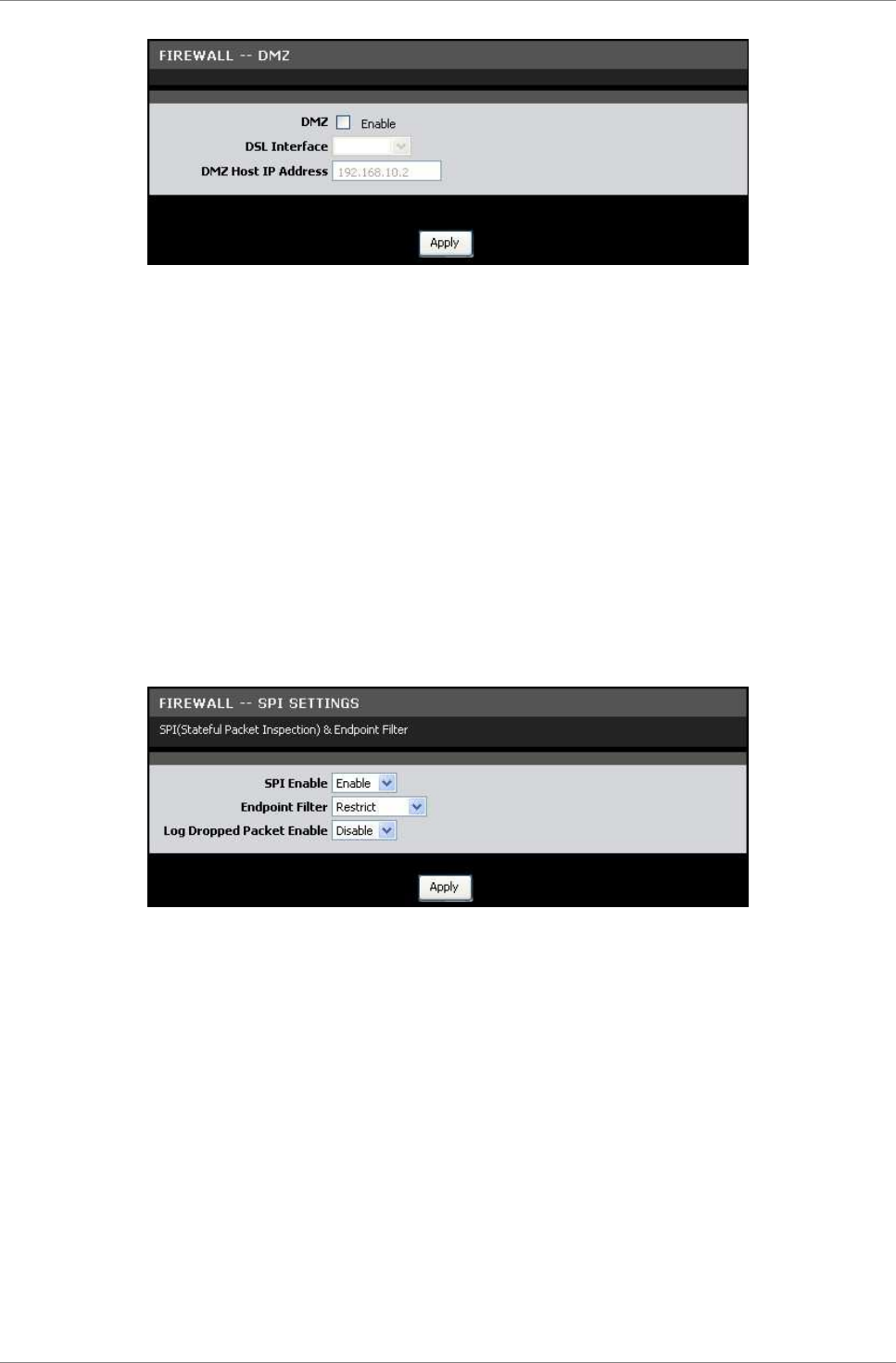
DMZ
A DMZ (Demilitarized Zone) sets a single computer, called a DMZ
host, on your network to have unrestricted Internet access. This
function is useful for gaming purposes or when a computer on your
network cannot access the Internet properly. However, this places
the DMZ host outside the firewall and exposes it to security risks.
To access the DMZ page, click ADVANCED > Firewall > DMZ or click
the DMZ button.
Advanced
TRENDnet DSLR-2001N 64
DMZ — Check this box to enable DMZ.
DSL Interface — Select the DSL interface to activate DMZ from the
drop-down list.
DMZ Host IP Address — Enter the IP address of the computer to set
as the DMZ host.
Check the Apply button to save and activate DMZ.
SPI Settings
SPI (Stateful Packet Inspection) filters more kinds of attacks by
closely examining packet data structures.
To access the SPI Settings page, click ADVANCED > Firewall > SPI
Settings or click the SPI Settings button.
SPI Enable — Select whether to enable or disable the SPI function.
Endpoint Filter — Select an endpoint filter option:
•
Independent: Forwards all incoming traffic from an open
port to the application that opened the port.
•
Restrict: Incoming traffic must match the IP address of the
outgoing connection.
Log Dropped Packet Enabled — Select whether to enable or disable
logging of dropped packets from your network or the Internet.
Click the Apply button to save and activate the SPI settings.
Advanced
TRENDnet DSLR-2001N 65
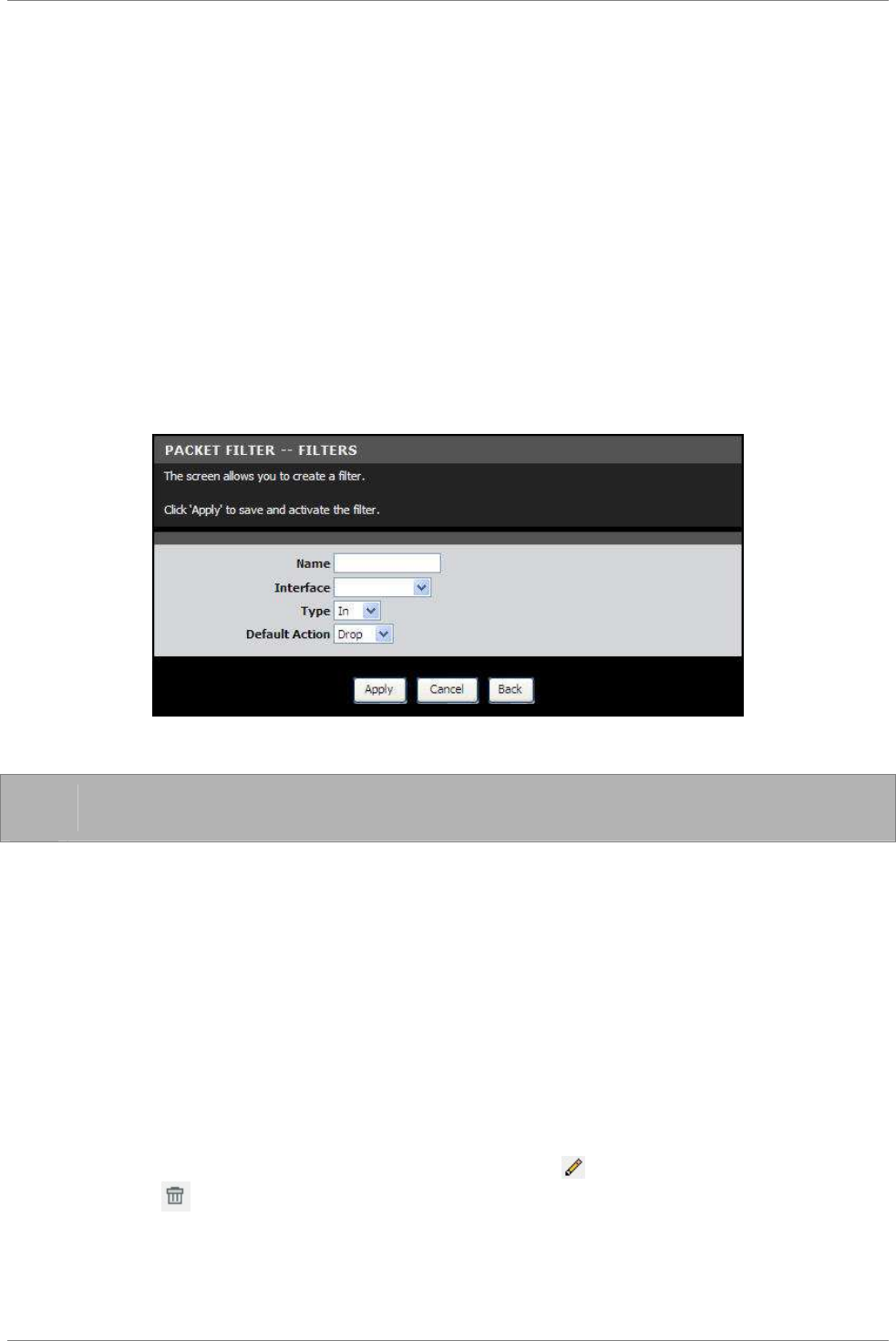
6.8 Packet Filter
Filters & Rules
This page allows you to create packet filters and rules. These
filters are used to check each data that passes within your
network. If the packet data does not meet the requirements, the
packet is either dropped or rejected.
To access the Filters & Rules page, click ADVANCED > Packet Filter
> Filters & Rules or click the Filters & Rules button.
Filters
Click the Add button to create a new filter.
Name — Enter desired filter name.
☞
NOTE: The filter name cannot contain spaces.
Interface — Select the interface to implement the filter.
Type — Select In to filter incoming packets or select Out to
filter outgoing packets.
Default Action — Select Drop to drop the packets or select Permit
to allow packets to pass through if the rule requirement is met.
Click the Apply button to save the filter or click the Cancel
button to discard your changes.
The new entry is listed on the FILTERS table. An Index and Key are
automatically assigned to each filter that you create. The Key is
used to identify the filter when assigning rules.
To edit a filter, click the corresponding icon. To delete a
filter, click the corresponding icon.
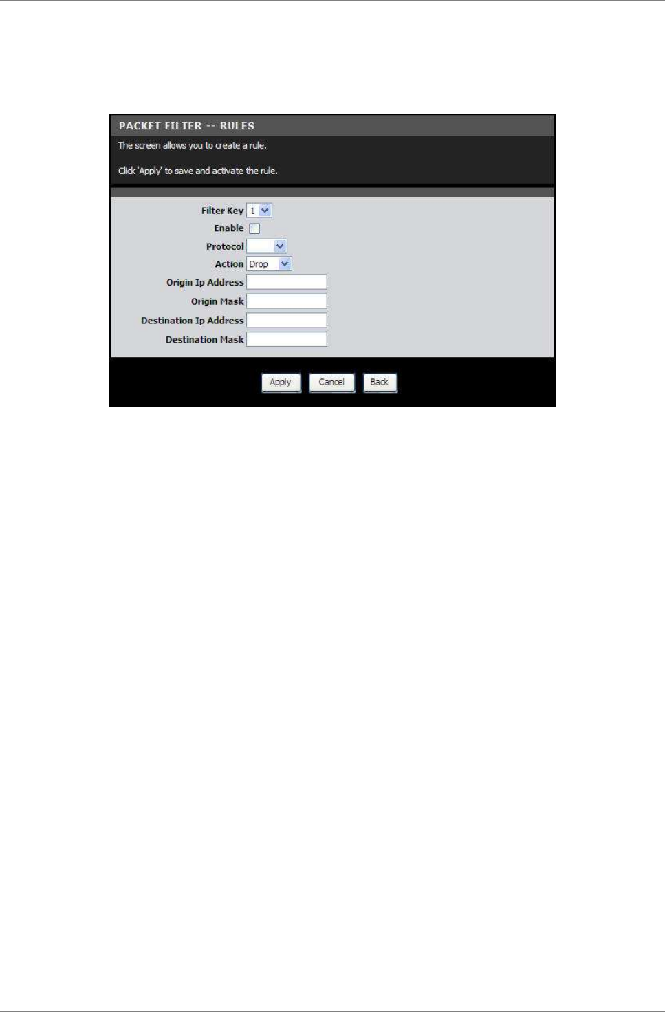
Advanced
TRENDnet DSLR-2001N 66
Rules
After creating filters, click the Add button to set the rules on
how to implement the filters.
Filter Key — Select the filter to assign the rule.
Enable — Check this box to enable this rule.
Protocol — Select a protocol from the drop-down list. Options are
TCP, UDP, or ICMP.
Action — Select the action to execute when the rule requirement is
met. Options are:
•
Drop: Select to drop the packets if the rule requirement is
met.
•
Permit: Select to allow packets to pass through if the rule
requirement is met.
•
Reject: Select to reject the packets if the rule
requirement is met. Select the Reject Type from the drop-
down list.
Depending on the selected protocol and the selected action, the
fields below may or may not be displayed on the screen.
Origin IP Address — Enter the IP address of the origin of the
packets.
Origin Mask — Enter the subnet mask of the origin of the packets.
Destination IP Address — Enter the IP address of the destination
of the packets.
Destination Mask — Enter the subnet mask of the destination of the
packets.
Origin Start Port and Origin End Port — Enter the starting and
ending port range of the origin of the packets.
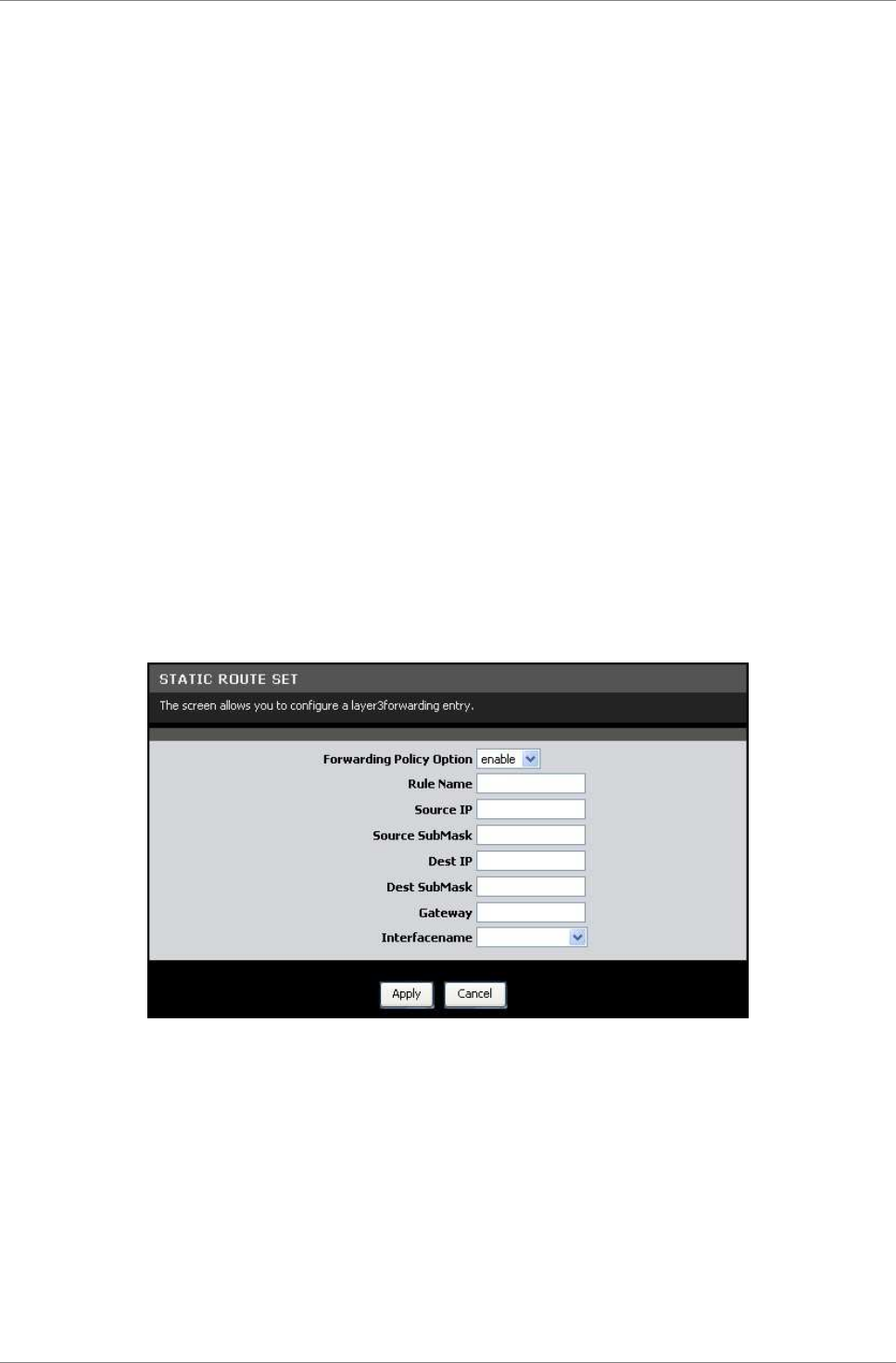
Advanced
TRENDnet DSLR-2001N 67
Destination Start Port and Destination End Port — Enter the
starting and ending port range of the destination of the packets.
ICMP Type — Select an ICMP type from the drop-down list. If the
selected type is met, the filter is implemented.
Click the Apply button to save and activate the rule or click the
Cancel button to discard your changes.
Statistics
This page displays the filter and rule statistics.
To access the Statistics page, click ADVANCED > Packet Filter >
Statistics or click the Statistics button.
Click the Refresh button to refresh the list.
6.9 Static Route
This page allows you to create routing tables.
To access the Static Route page, click ADVANCED > Static Route.
Click the Add button to create a static route.
Forwarding Policy Option — Select whether to enable or disable
routing.
Rule Name — Enter desired rule name.
Source IP — Enter the source IP address.
Source SubMask — Enter the source subnet mask.
Dest IP — Enter the destination IP address.
Dest SubMask — Enter the destination subnet mask.
Gateway — Enter the gateway.
Interface name — Select the interface to implement the routing.

Advanced
TRENDnet DSLR-2001N 68
Click the Apply button to save and activate the static route or
click the button to discard your changes.
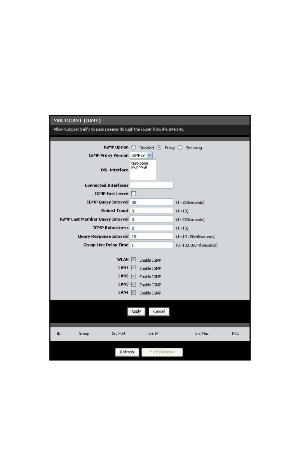
Advanced
TRENDnet DSLR-2001N 69
6.10 Multicast
Internet Group Management Protocol (IGMP) manages members of
groups of devices, called IP multicast groups. IGMP is used by IP
hosts and adjacent multicast routers to establish multicast group
membership. It is an integral part of the IP multicast
specification, like ICMP for unicast connections. IGMP is used for
online video and gaming, and allows more efficient use of
resources that support these applications.
To access the Multicast page, click ADVANCED > Multicast.
IGMP Option — Select an IGMP option. Options are: Disabled, Proxy,
and Snooping.
IGMP Fast Leave — Check this box to enable IGMP fast leave.
IGMP Proxy
IGMP proxy enables your Modem Router to forward multicasts
traffics between LAN and WAN networks. Select IGMP Proxy Version
and DSL Interface. Enter values for IGMP Query Interval, Robust
Count, IGMP Last Member Query Interval, IGMP Robustness, Query
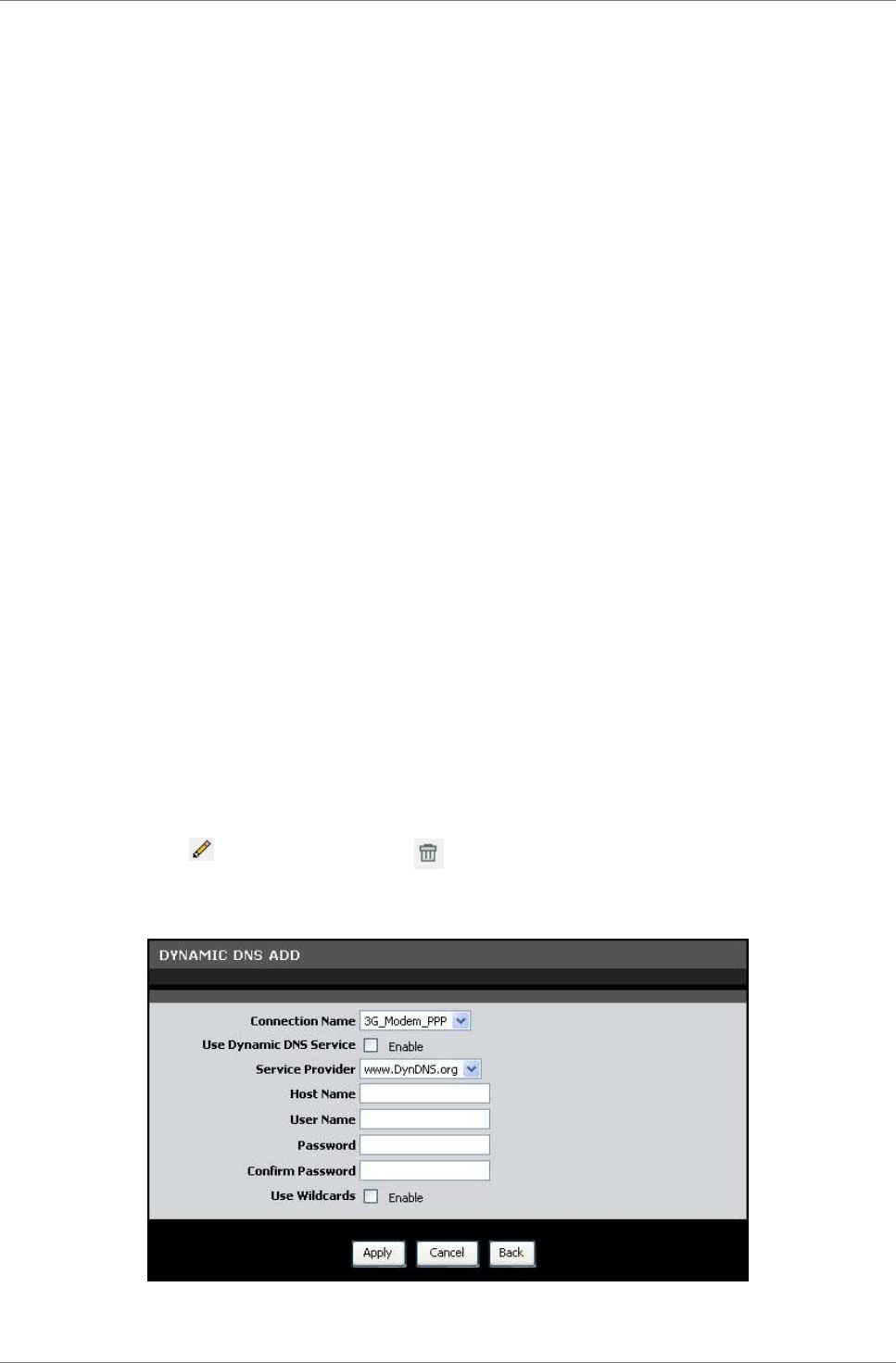
Advanced
TRENDnet DSLR-2001N 70
Response Interval, and Group Live Delay Time. If you are unsure
about them, leave the default values.
IGMP Snooping
With IGMP snooping, your Modem Router can make intelligent
multicast forwarding to connections that have group members
attached. As a result, IGMP snooping prevents or reduces traffic
on the interface that is not registered as a receiver of a
specific multicast group.
Select IGMP Proxy Version. Enter values for IGMP Query Interval,
Robust Count, IGMP Last Member Query Interval, IGMP Robustness,
Query Response Interval, and Group Live Delay Time.
Check the boxes to enable IGMP for WLAN, LAN1, LAN2, LAN3, and
LAN4.
Click the Apply button to save your changes or click the Cancel
button to discard your changes.
6.11 Dynamic DNS
Each time your Modem Router connects to the Internet, your ISP
assigns a different IP address to your device. In order to access
your device from the WAN side, you need to manually track the IP
that is currently used. The Dynamic DNS (DDNS) feature allows you
to register your device with a DNS server and use the same host
name to access your device.
To access the Dynamic DNS page, click ADVANCED > Dynamic DNS.
The table lists the current DDNS. To edit an entry, click the
corresponding icon. To delete an entry, click the corresponding
icon.
To add DDNS, click the Add button.
Connection Name — Select a connection from the drop-down list.
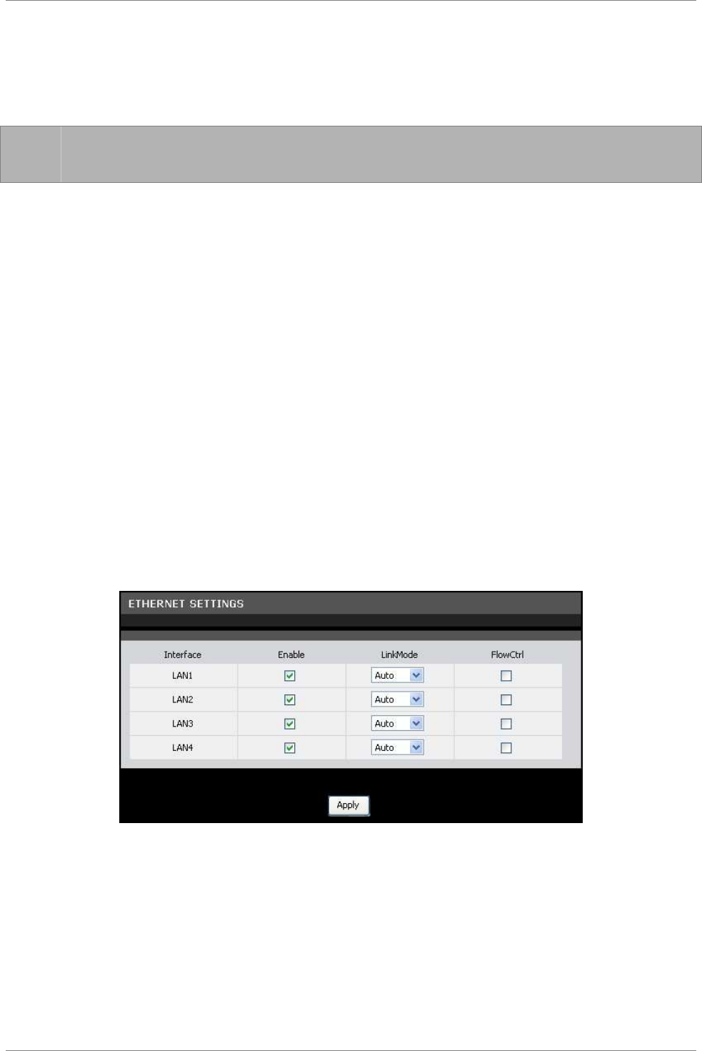
Advanced
TRENDnet DSLR-2001N 71
Use Dynamic DNS Service — Check this box to register this account
to the DNS server.
Service Provider — Select a service provider from the drop-down
list.
☞
NOTE: Additional charges may be incurred depending on the
selected service provider.
Host Name — Enter a domain name to be registered to the DNS server.
User Name — Enter the user name of your DNS account assigned by
the service provider.
Password — Enter the password of your DNS account assigned by the
service provider. Re-enter the password on the Confirm Password
field.
Use Wildcards — Check this box to enable searching with wildcards.
Click the Apply button to save your changes or click the Cancel
button to discard your changes.
6.12 Ethernet Setting
This page allows you to set the link mode and enable flow control
for each of the four LAN ports of your Modem Router.
To access the Ethernet Setting page, click ADVANCED > Ethernet
Setting.
Check the Enable box of the LAN interface to enable the port.
Select the LinkMode from the drop-down list. Options are: Auto,
10Half, 10Full, 100Half, and 100Full.
Check the FlowCntrl box of the LAN interface to enable flow
control.
Click the Apply button to save your changes.
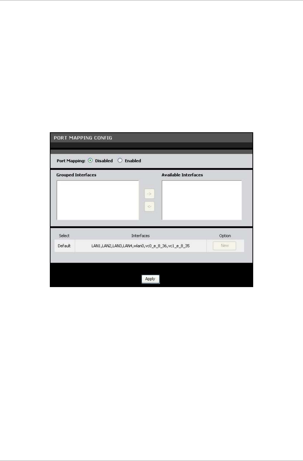
Advanced
TRENDnet DSLR-2001N 72
6.13 Port Mapping
Port mapping allows you to group interfaces for traffic control.
Traffic is isolated from group to group. Therefore, traffic coming
from an interface of a group can only be flowed to the interfaces
in the same group.
By default, all interfaces belong to the Default group. You can
create new groups and move interfaces to other groups. However, an
interface can only be a member of one group.
To access the Port Mapping page, click ADVANCED > Port Mapping.
Port Mapping — Check this box to enable port mapping.
To Create New Groups
1. Click the New button. An empty group appears on the table.
2. Click the radio button to select the empty group.
3. Add members to the group. To do so, select an interface from
the Available Interfaces panel. Then click the <- button to
add the selected interface to the Grouped Interfaces panel.
4. Repeat step 3 to add more members to the group.
5. Click the Apply button to save your changes.
To Modify Groups
1. Click the radio button to select the group to modify.
2. To add a group member or remove a member from the group,
select the interface, then click the <- or -> buttons.

Advanced
TRENDnet DSLR-2001N 73
3. Click the Apply button to save your changes.
To Delete Groups
Click the corresponding Delete button of the group to delete. The
members of that group automatically revert back to the Default
group.
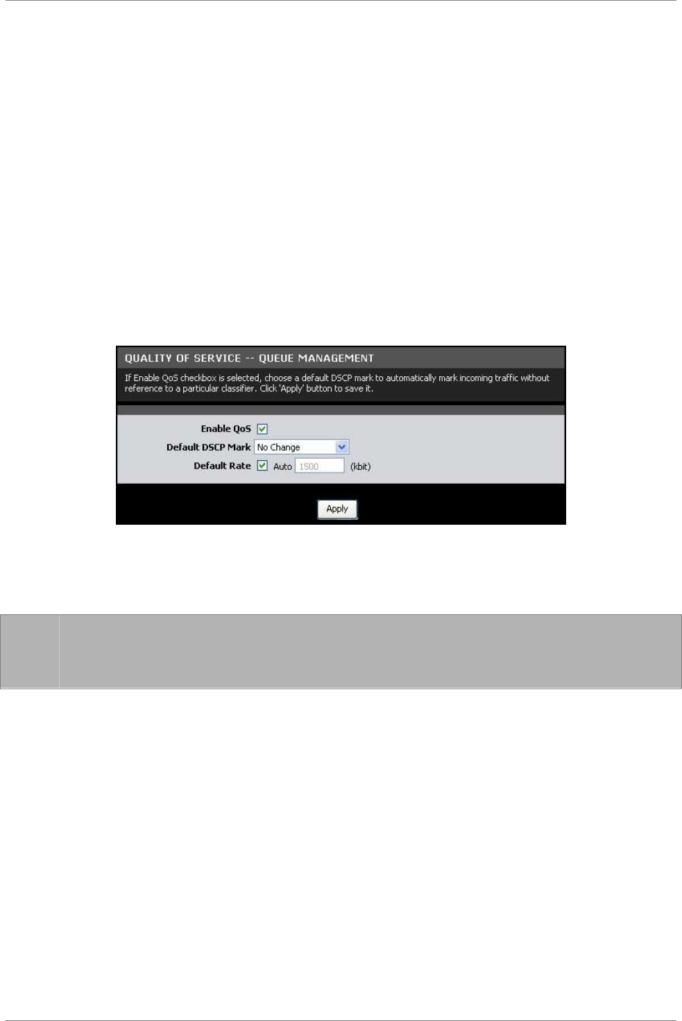
Advanced
TRENDnet DSLR-2001N 74
6.14 Quality of Service (QoS)
Quality of Service (QoS) is a network standard that assigns the
priorities of traffic that passes through your Modem Router. This
ensures that demanding real-time applications, such as video
streaming, are given priority over other data.
Queue Management
This page allows you to enable QoS and choose Differentiated
Services Code Point (DSCP) markings to automatically mark incoming
traffic without reference to a particular classifier.
To access the Queue Management page, click ADVANCED > Quality of
Service > Queue Management or click the Queue Management button.
Enable QoS — Check this box to enable the QoS feature.
Default DSCP Mark — Select a DSCP mark from the drop-down list.
The DSCP mark is used to classify and prioritize types of packets.
☞
NOTE: If the drop-down list does not contain the DSCP marking
that you want, select either Private DSCP value or Public
DSCP value.
Default Rate — Check the Auto box to set the rate to its auto
default or uncheck the box to enter the QoS rate manually.
Click the Apply button to save and apply the QoS settings.
Queue Config
This page allows you to configure a QoS queue entry and assign it
to a specific network interface. Each of the queues can be
configured for a specific precedence. The queue configuration will
be used in Queue Classification to place ingress packets
appropriately.
To access the Queue Config page, click ADVANCED > Quality of
Service > Queue Config or click the Queue Config button.
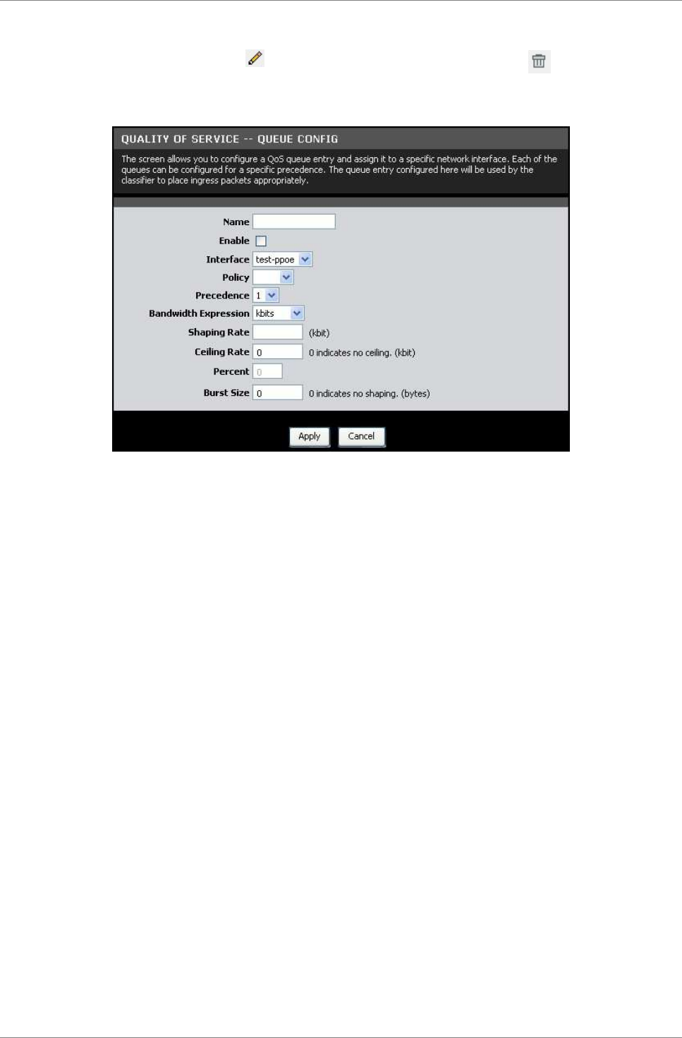
Advanced
TRENDnet DSLR-2001N 75
The table displays QoS queue configurations. To edit an entry,
click the corresponding icon. To delete an entry, click the
corresponding icon.
To configure QoS queue entries, click the Add button.
Name — Enter a QoS queue entry name.
Enable — Check this box to enable this queue.
Interface — Select the interface to implement this QoS queue.
Policy — Select the queue policy. Options are:
•
SP: In Strict Priority (SP), packets with a high priority
are processed first. Not until the first queue is empty
will another queue be processed.
•
WFQ: In Weighted Fair Queuing (WFQ), each queue can be
given a different priority level. Each traffic is assigned
to a class and each class is given its own queue.
Precedence — Select the precedence from the drop-down list.
Bandwidth Expression — Select one of the following options:
•
Kbits: Enter the Shaping Rate and Ceiling Rate.
•
Percent: Enter the Percent.
Burst Size — Enter burst size.
Click the Apply button to save the queue configuration or click
the Cancel button to discard your changes.

Advanced
TRENDnet DSLR-2001N 76
Queue Classification
This page allows you to configure classification rules to classify
upstream traffic and assign queues which define the precedence,
interface, and optionally overwrite the IP header DSCP byte. A
rule consists of a class name and at least one condition. All the
specified conditions in the classification rule must be satisfied
for the rule to take effect.
To access the Queue Classification page, click ADVANCED > Quality
of Service > Queue Classification or click the QoS Classification
button.
The table displays QoS queue classification rules. To edit an
entry, click the corresponding icon. To delete an entry, click
the corresponding icon.
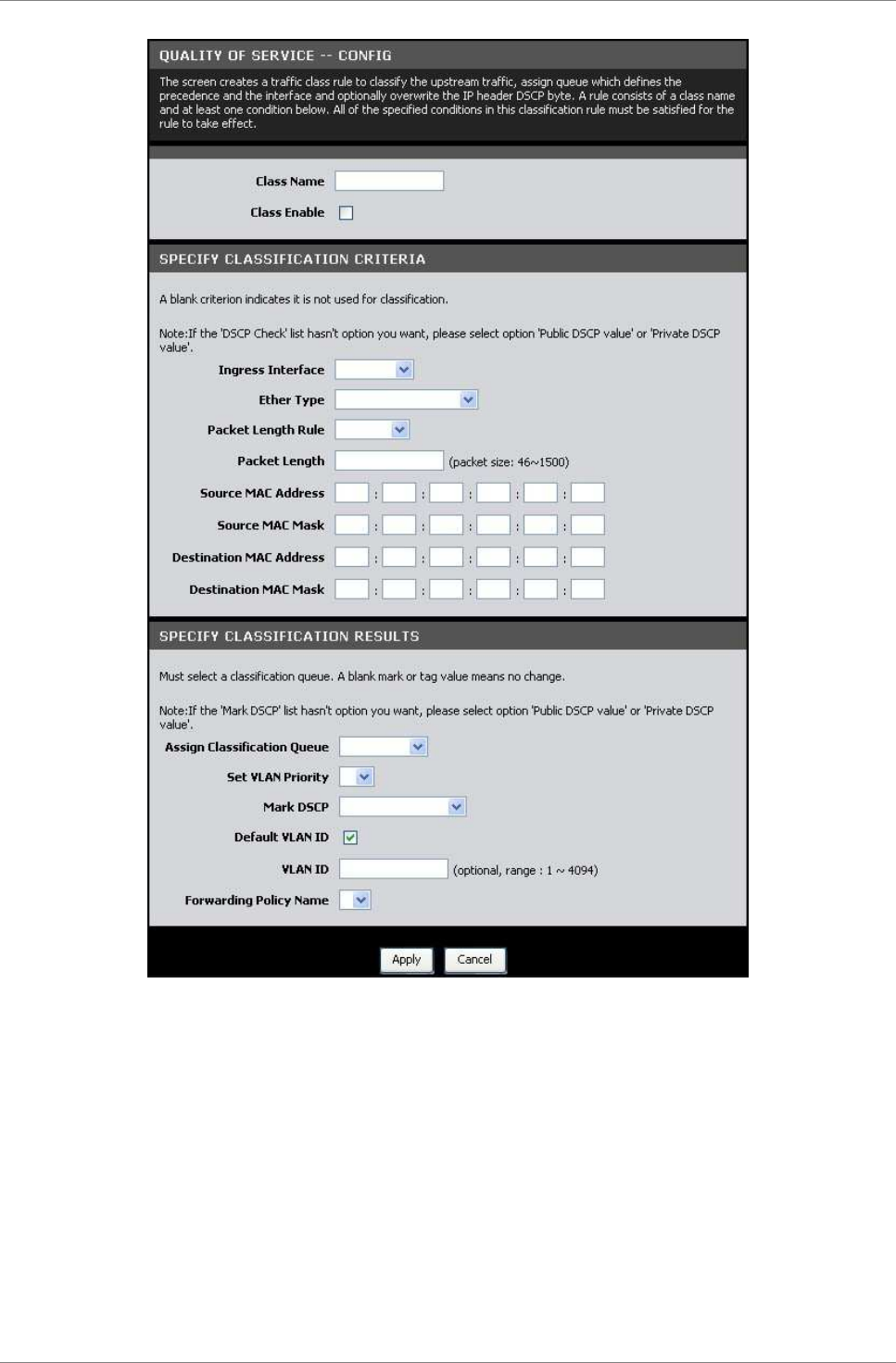
Advanced
TRENDnet DSLR-2001N 77
Class Name — Enter a class name.
Class Enable — Check this box to enable the class.
Specify Classification Criteria
You can classify traffic based on ingress interface, Ether type,
packet length, source or destination MAC address/ MAC Mask, or a
combination of them. Select an option or enter the values on the
fields that you want to use for the criteria. Otherwise, leave the
fields empty.
Depending on the selected Ether Type, the succeeding required
information may vary.

Advanced
TRENDnet DSLR-2001N 78
If packet length is used as a criteria, select the Packet Length
Rule from the drop-down list and enter the Packet Length.
Specify Classification Results
Some fields may not be applicable; if so, leave inapplicable
fields empty.
Assign Classification Queue — Select the classification queue from
the drop-down list. Only enabled classification queues from the
Queue Classification page are listed here.
Set VLAN Priority — To set the VLAN priority, select a priority
from the drop-down list
Mark DSCP — Select the DSCP mark from the drop-down list. If the
DSCP mark that you want is not listed, select either Public DSCP
value or Private DSCP value.
Default VLAN ID — Check this box to use the default VLAN ID.
VLAN ID — If Default VLAN ID is not checked, enter preferred VLAN
ID.
Forwarding Policy Name — Select the forwarding policy name from
the drop-down list.
Click the Apply button to save and apply the settings or click the
Cancel button to discard your changes.
QoS Status
This page allows you to view the QoS status.
To access the QoS Status page, click ADVANCED > Quality of Service
> QoS Status or click the QoS Status button.
Click the Refresh button to refresh the table.
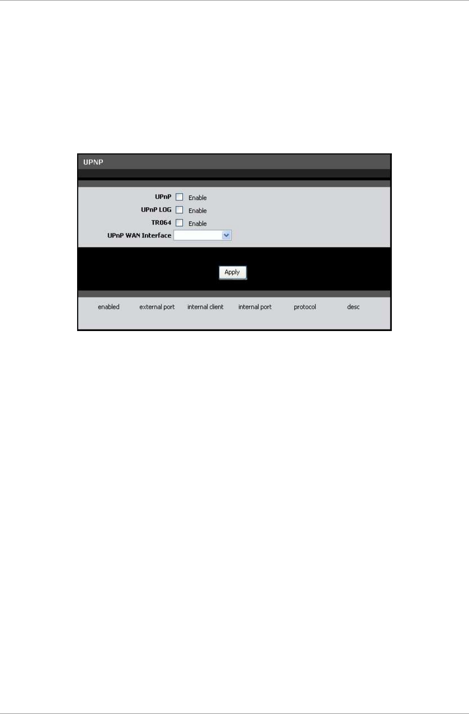
Advanced
TRENDnet DSLR-2001N 79
6.15 UPnP
Universal Plug and Play (UPnP) allows automatic discovery and
control of services available on the network from other devices
without user intervention. This feature is commonly used for
gaming and video streaming. If you feel that UPnP is a security
concern, disable this feature.
To access the UPnP page, click ADVANCED > UPnP.
UPnP — Check this box to enable the UPnP feature.
UPnP LOG — Check this box to log UPnP status.
TR064 — Check this box to enable TR064.
UPnP WAN Interface — Select the interface to implement UPnP.
Click the Apply button to save and apply the settings.
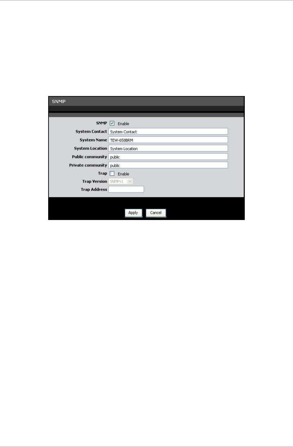
Advanced
TRENDnet DSLR-2001N 80
6.16 SNMP
Simplified Network Management Protocol (SNMP) is a troubleshooting
and management protocol that is used to monitor the status and
change the configurations of your Modem Router locally or remotely.
It also allows configuring and receiving of trap messages from
network devices that are configured for SNMP.
To access the SNMP page, click ADVANCED > SNMP.
SNMP — Check this box to enable SNMP.
System Contact — Enter the contact person or contact information
for your Modem Router.
System Name — Enter an assigned name for your Modem Router.
System Location — Enter an assigned location for your Modem Router.
Public Community and Private Community — Enter a public and
private community name.
Trap — Check this box to enable the Trap function, then provide
the following information:
•
Trap Version: Select an SNMP trap version from the drop-
down list.
•
Trap Address: Enter the destination IP address of the SNMP
trap.
Click the Apply button to save and apply changes or click the
Cancel button to discard your changes.
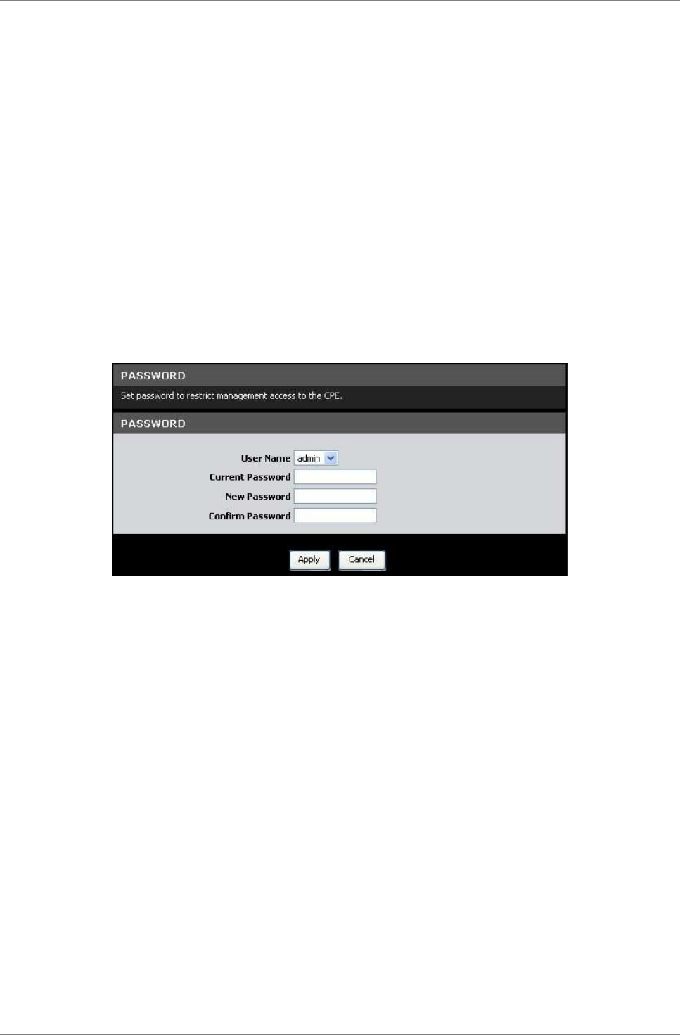
Maintenance
TRENDnet DSLR-2001N 81
Chapter 7: Maintenance
The Maintenance menu allows you to configure the web-based utility
settings, such as password, remote management, backup/restore
options, firmware upgrades, and others.
7.1 Password
By default, the log in user name and password are “admin”. For
security reasons, it is strongly recommended to change the
password.
To access the Password page, click MAINTENANCE > Password.
User Name — Select the user account: admin or user.
Current Password — Enter the current password.
New Password — Enter desired password.
Confirm Password — Re-enter the new password.
Click the Apply button to save your changes or click the Cancel
button to discard your changes.
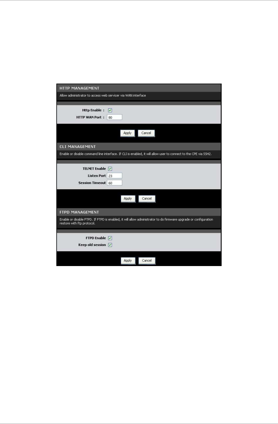
Maintenance
TRENDnet DSLR-2001N 82
7.2 Remote Management
This page allows you to enable remote devices to manage your Modem
Router using the Hypertext Transfer Protocol (HTTP), Command-Line
Interface (CLI), and File Transfer Protocol Daemon (FTPD).
To access the Remote Management page, click MAINTENANCE > Remote
Management.
HTTP Management
Check the Http Enable box to allow network administrators to
remotely access the web-based utility via WAN interface. Click the
Apply button to save your changes or click the Cancel button to
discard your changes.
CLI Management
Check the TELNET Enable box to allow network administrators to use
the command-line interface.
Listen Port — Enter the Listen port.
Session Timeout — Enter the time wherein the session will
automatically timeout after being idle for the specified time.
Click the Apply button to save your changes or click the Cancel
button to discard your changes.
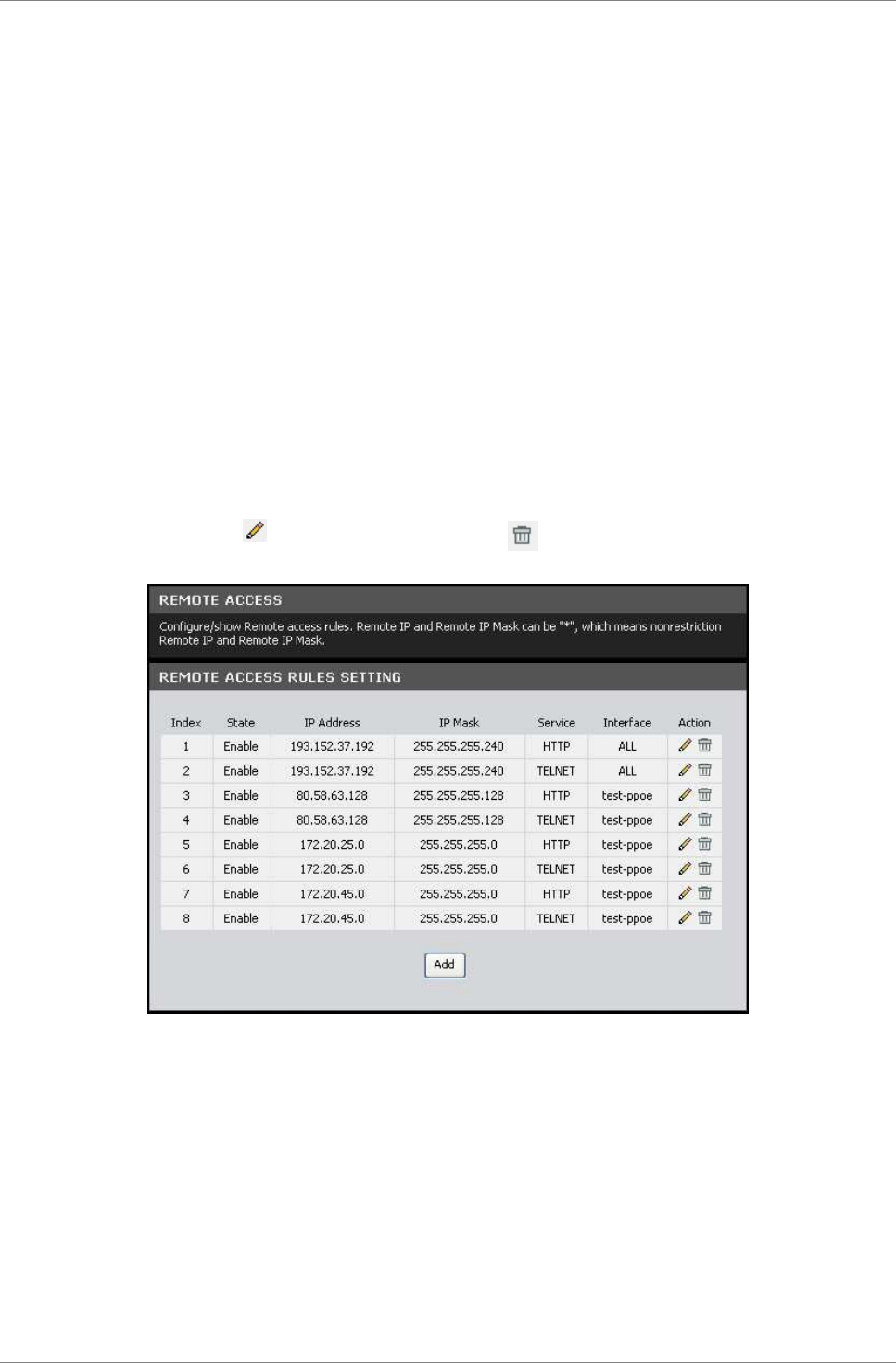
Maintenance
TRENDnet DSLR-2001N 83
FTPD Management
Check the FTPD Enable box to allow network administrators to
upgrade the firmware or restore configurations using the FTP.
Keep old session — Check to retain the old session.
Click the Apply button to save your changes or click the Cancel
button to discard your changes.
7.3 Remote Access
This page allows you to create and edit remote access rules. You
can specify the IP address or the subnet mask of devices that are
allowed or denied to remotely access your Modem Router and set the
type of management service that they can access.
To access the Remote Access page, click MAINTENANCE > Remote
Accesss.
The table lists the remote access rules. To edit an entry, click
the corresponding icon. To delete an entry, click the
corresponding icon.
To create remote access rules, click the Add button.
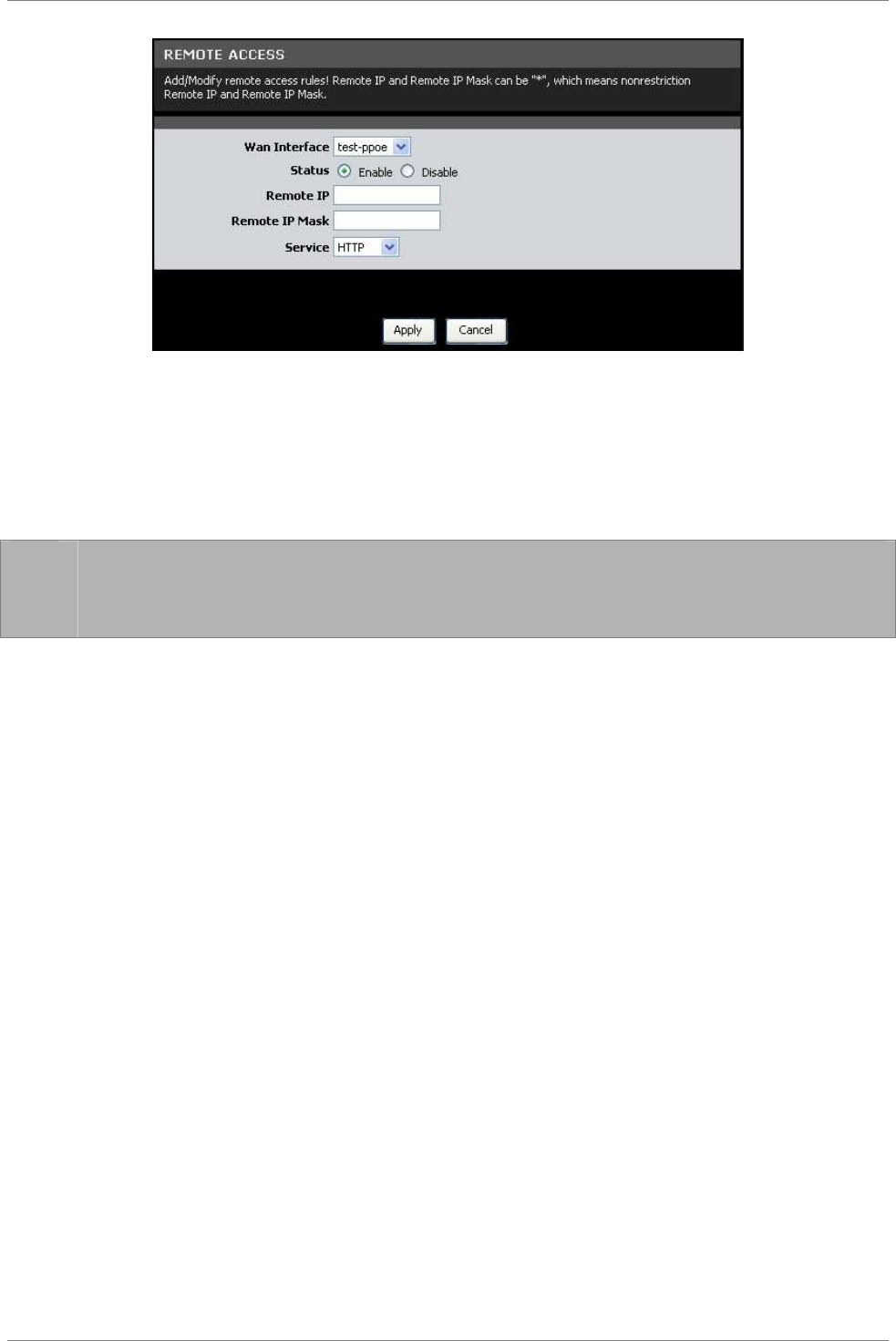
Maintenance
TRENDnet DSLR-2001N 84
Wan Interface — Select the interface from the drop-down list.
Status — Select whether to enable or disable remote access of the
device.
Remote IP — Enter the IP address of the remote device.
Remote IP Mask — Enter the IP mask of the remote device.
☞
NOTE: To allow or deny all devices to remotely access your
Modem Router, enter “*” on the Remote IP and Remote IP Mask
fields.
Service — Select the type of remote management service that the
device can or cannot access.
Click the Apply button to save your changes or click the Cancel
button to discard your changes.
7.4 TR069 Setting
TR069 is a protocol that provides communication between customer-
premises equipments (CPE) such as telephones, routers, or set-top
boxes, and an Auto-Configuration Server (ACS).
To access the TR069 Setting page, click MAINTENANCE > TR069
Setting.
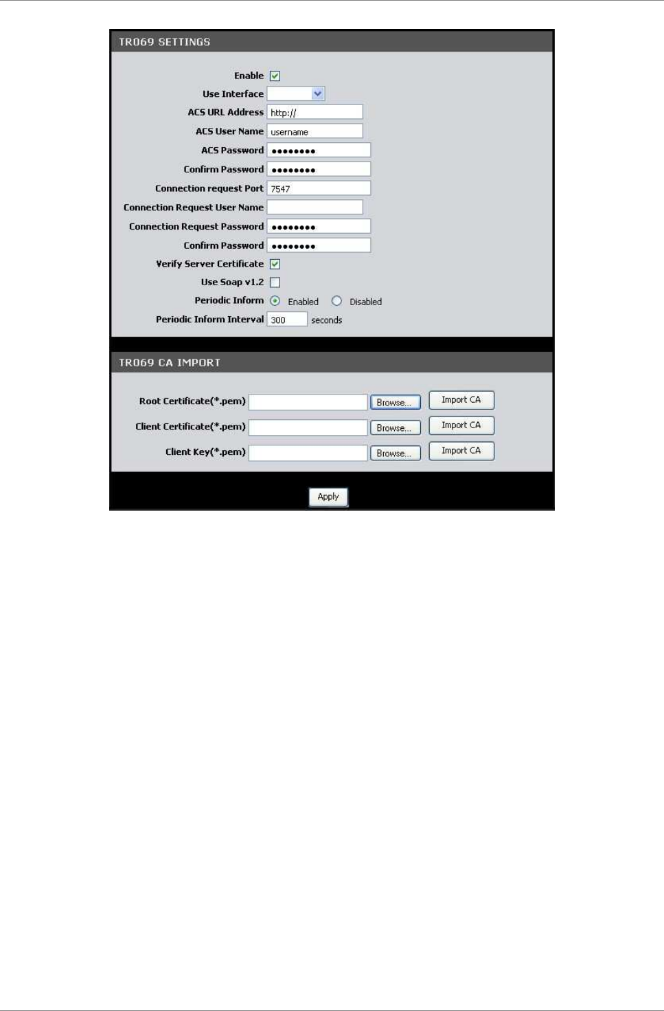
Maintenance
TRENDnet DSLR-2001N 85
TR069 Settings
Enable — Check this box to enable TR069.
Use Interface — Select the interface to implement TR069.
ACS URL Address — Enter the URL of the Auto-Configuration Server
(ACS)
ACS User Name — Enter the user name of your Modem Router when
connecting to the ACS.
ACS Password — Enter the password that your Modem Router should
use when connecting to the ACS. Re-enter the password on the
Confirm Password field.
Connection Request Port —Enter the port that issues the request.
Connection Request User Name — Enter the connection request user
name.
Connection Request Password — Enter the connection request
password. Re-enter the password on the Confirm Password field.
Verify Server Certificate — Check this box to verify server
certificates.
Use Soap v1.2 — Check this box to enable the SOAP protocol.

Maintenance
TRENDnet DSLR-2001N 86
Periodic Inform — When enabled, your Modem Router will send remote
procedure calls (RPC) to the ACS server at system startup and will
continue sending RPCs periodically. When disabled, your Modem
Router will send RPCs to the ACS server at system startup only.
Periodic Inform Interval — Enter the interval time of sending RPCs.
TR069 CA IMPORT
To import certificates, do the following:
1. Click the Browse button.
2. Browse for the certificate, then click the Open button.
3. The file is displayed on the field. Click the Import CA
button to import.
Click the Apply button to save your changes or click the Cancel
button to discard your changes.
Maintenance
TRENDnet DSLR-2001N 87
7.5 Init Script
This page allows you to show, delete, and import initialization
scripts running on customer-premises equipment (CPE), such as
telephones, routers, or set-top boxes, during system startup or
shutdown.
To access the Init Script page, click MAINTENANCE > Init Script.
Init start scripts are scripts that run before the system starts
up. Init end scripts are scripts that run before the system shuts
down.
To import scripts, do the following:
1. Click the Browse button.
2. Browse for the file, then click the Open button.
3. Click the Import Script button.
To show the scripts on your computer, click the Show Start/End
Script button.
To delete the scripts on your computer, click the Delete button.
Maintenance
TRENDnet DSLR-2001N 88
7.6 SysLog
This page allows you to enable and configure system logs such as
device status, events, and activities. Logs can be sent to the
network administrator via e-mail.
To access the SysLog page, click MAINTENANCE > SysLog.
Log Generate Enable Options
Kernel Common Message — Check this box to generate logs. Click the
Apply button to save and apply the setting.
Log Rules Setting
The table displays current log rules. To edit an entry, click the
corresponding icon.
To create log rules, click the Add button. The screen below is
displayed.
1. Select Module and Facility.
2. Select Severity level. emerg is the highest level while debug
is the lowest level.
Maintenance
TRENDnet DSLR-2001N 89
3. Select Location: Remote Server or Mail.
4. The succeeding fields may vary depending on the selected
location. Enter the necessary information accordingly.
5. Click the Apply button to save your changes or click the
Cancel button to discard your changes.
E-mail Log Periodically
To log e-mails periodically, do the following:
1. Check the SMTP Server box to enable logging of e-mails
periodically.
2. Enter the SMTP Server IP, Source E-mail Address, and
Destination E-mail Address.
3. If SMTP Authentication is enabled, enter the SMTP Username
and SMTP Password. Re-enter the password in the Confirm
Password field.
4. Select the Frequency of logging e-mails.
5. Click the Apply button to save your changes or click the
Cancel button to discard your changes.
Maintenance
TRENDnet DSLR-2001N 90
7.7 Time Schedule
This page allows you create desired time schedule.
To access the Time Schedule page, click MAINTENANCE > Time
Schedule.
To create a new schedule, do the following:
1. On the Name field, enter desired schedule name.
2. Check the days to implement the schedule and select the time
period.
3. Click the Add button to save the schedule. The new entry is
listed on the TIME SCHEDULE LIST.
To delete a schedule, click the corresponding icon.
7.8 Firmware Upgrade
This page displays the current firmware version of your Modem
Router and allows you to install the upgrade.
To access the Firmware Upgrade page, click MAINTENANCE > Firmware
Upgrade.
Click the Browse button and browse for the file. Click the Apply
button to start firmware upgrade.

Maintenance
TRENDnet DSLR-2001N 91
☞
NOTE: Do not turn off or press the Reset button on your Modem
Router while firmware upgrade is in progress. This may cause
the system to crash.
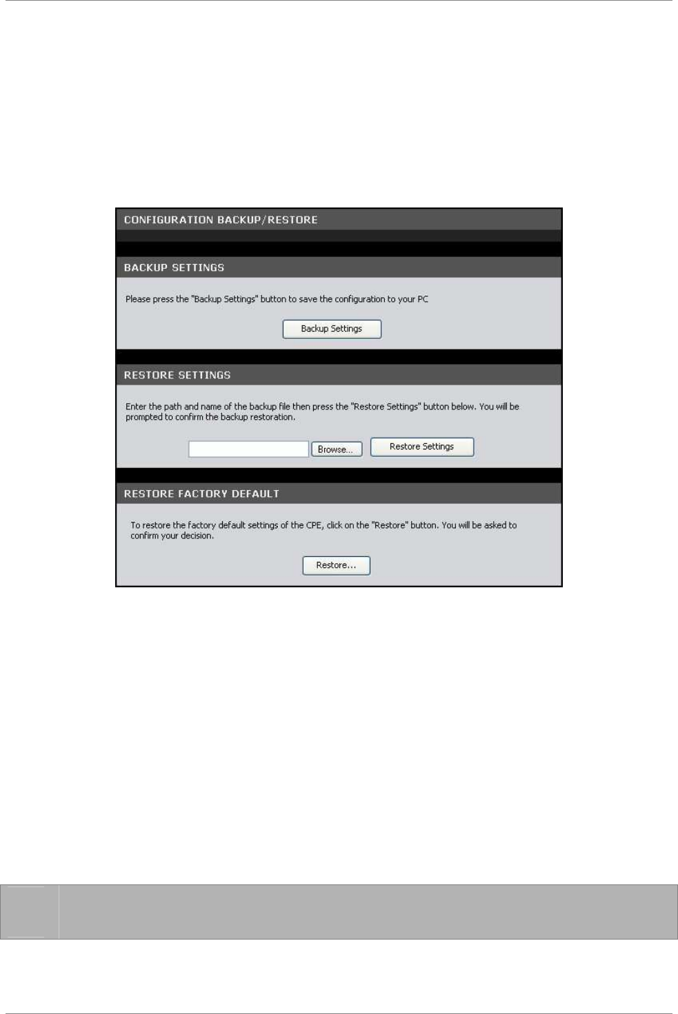
Maintenance
TRENDnet DSLR-2001N 92
7.9 Configuration Backup/Restore
This page allows you to save a backup of your current settings,
revert settings to a backup point, or restore the default factory
settings.
To access the Configuration Backup/Restore page, click MAINTENANCE
> Configuration Backup/Restore.
To backup the current settings, click the Backup Settings button.
To restore settings from a backup point, do the following:
1. Click the Browse button.
2. Browse for the backup file, and then click the Open button.
3. Click the Restore Settings button to restore.
You can restore the Modem Router to its factory defaults. However,
doing so will delete all your settings. To restore the factory
defaults, do the following:
1. Click the Restore button.
2. When prompted, click the OK button.
3. A warning message appears, click the OK button to continue.
☞
NOTE: Restoring to factory defaults may take some time. Do
not turn off your Modem Router.
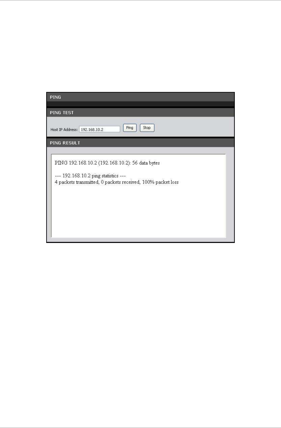
Maintenance
TRENDnet DSLR-2001N 93
7.10 Ping
Once you have configured your Modem Router, it is recommended to
ping the network devices to verify their connection. When you
execute a ping test, a series of packets are sent to a specific
computer. When the computer receives the packets, it will respond
with an acknowledgment that it received the packets.
To access the Ping page, click MAINTENANCE > Ping.
Host IP Address — Enter the IP address of the network device that
you want to ping. Click the Ping button to start ping. The results
are displayed on the PING RESULT screen.
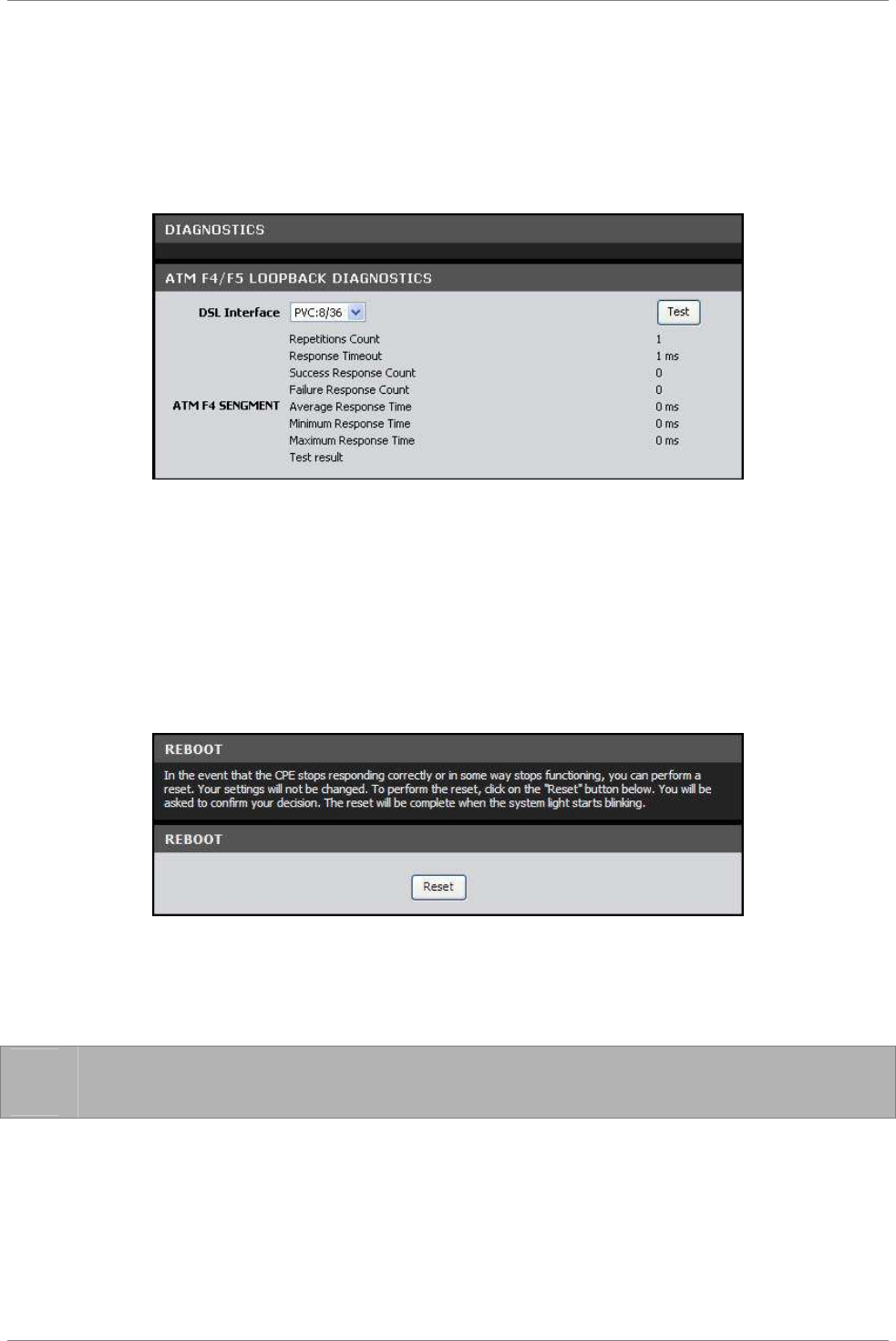
Maintenance
TRENDnet DSLR-2001N 94
7.11 Diagnostics
This page allows you to test the connectivity of the physical and
protocol layers on the WAN side.
To access the Diagnostics page, click MAINTENANCE > Diagnostics.
To start the test, select the DSL Interface from the drop-down
list, and then click the Test button.
7.12 Reboot Device
In the event that your device does not respond correctly or stops
responding, reset your device. All your settings will be retained.
1. Click the Reset button.
2. Click OK to confirm.
3. When prompted, click OK.
☞
NOTE: Resetting your Modem Router may take some time. Do not
turn off the power until the reset is completed.
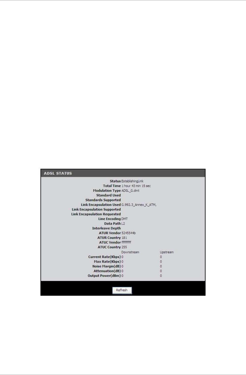
Status
TRENDnet DSLR-2001N 95
Chapter 8: Status
The Status menu provides the current status and settings of your
Modem Router.
8.1 Summary
This page displays the summary of the system, DSL link, ATM PVC,
Internet connection, LAN, and wireless ports status.
To access the Summary page, click STATUS > Summary.
8.2 ADSL Info
This page displays the status of your DSL line.
To access the ADSL Info page, click STATUS > ADSL Info.
Click the Refresh button to refresh the information.
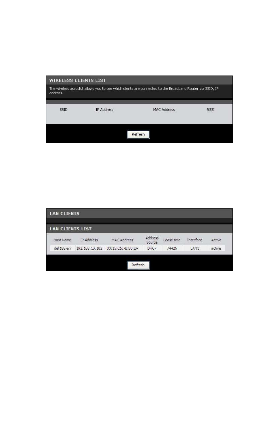
Status
TRENDnet DSLR-2001N 96
8.3 Wireless Clients
This page displays the clients connected on your network via
wireless connection.
To access the Wireless Clients page, click STATUS > Wireless
Clients.
Click the Refresh button to refresh the information.
8.4 LAN Clients
This page displays the clients connected on your network.
To access the LAN Clients page, click STATUS > LAN Clients.
Click the Refresh button to refresh the information.
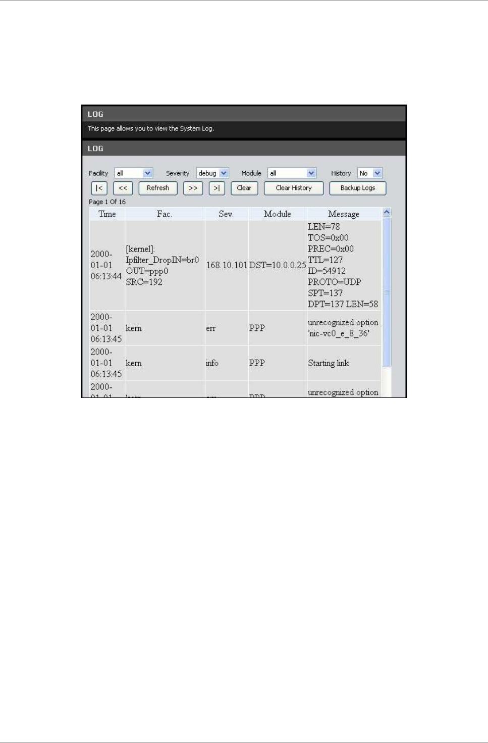
Status
TRENDnet DSLR-2001N 97
8.5 Logs
This page allows you to view, clear, and backup system logs.
To access the Logs page, click STATUS > Logs.
You can filter the list by selecting a particular Facility,
Severity, Module, or History from the drop-down lists.
Click the Clear History button to delete old logs.
Click the Backup Logs button to save a backup of the logs.
Click the
|
< << >> >
|
buttons to scroll through the logs.
Click the Refresh button to refresh the information.
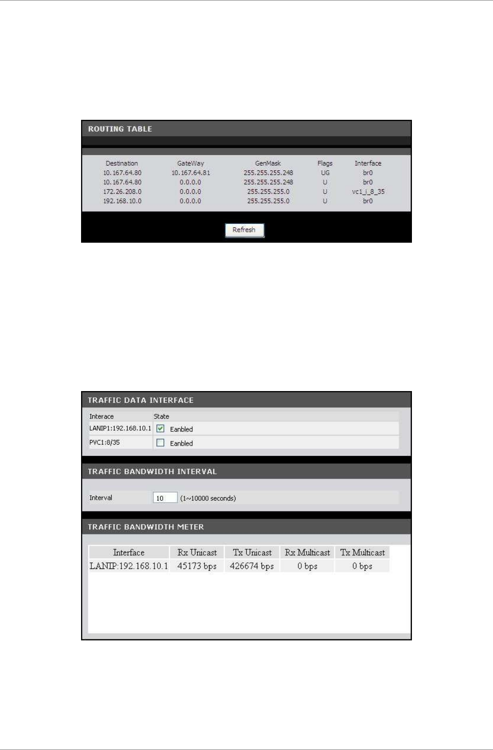
Status
TRENDnet DSLR-2001N 98
8.6 Routing Table
This page displays the destination routes commonly accessed by
your network.
To access the Routing Table page, click STATUS > Routing Tables.
Click the Refresh button to refresh the information.
8.7 Traffic Meter
This page displays the transmission and reception statistics of
packets that pass through the specified interface.
To access the Traffic Meter page, click STATUS > Traffic Meter.
Traffic Data Interface
The table lists the available interfaces on your network. Check
the State box of the interface to view its traffic. You may check
more than one interface.
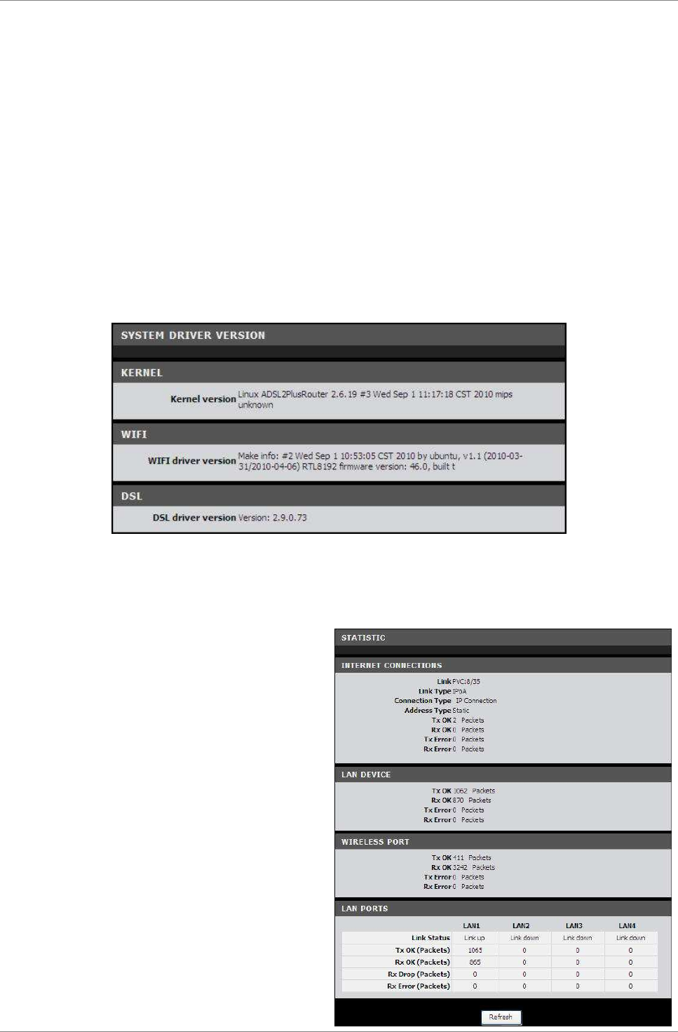
Status
TRENDnet DSLR-2001N 99
Traffic Bandwidth Interval
Interval — Enter the interval of refreshing the traffic bandwidth.
Traffic Bandwidth Meter
This table lists the current traffic.
8.8 Driver Version
This page displays the current kernel, Wi-Fi, and DSL driver
versions.
To access the Driver Version page, click STATUS > Driver Version.
8.9 Statistics
Basic Statistics
This page displays the
transmission and reception
statistics of the Internet
connection, LAN device,
wireless port, and the LAN
ports.
To access the Basic Statistics
page, click STATUS > Statistics
> Basic Statistics or click the
Basic Statistics button.
Click the Refresh button to
refresh the information.
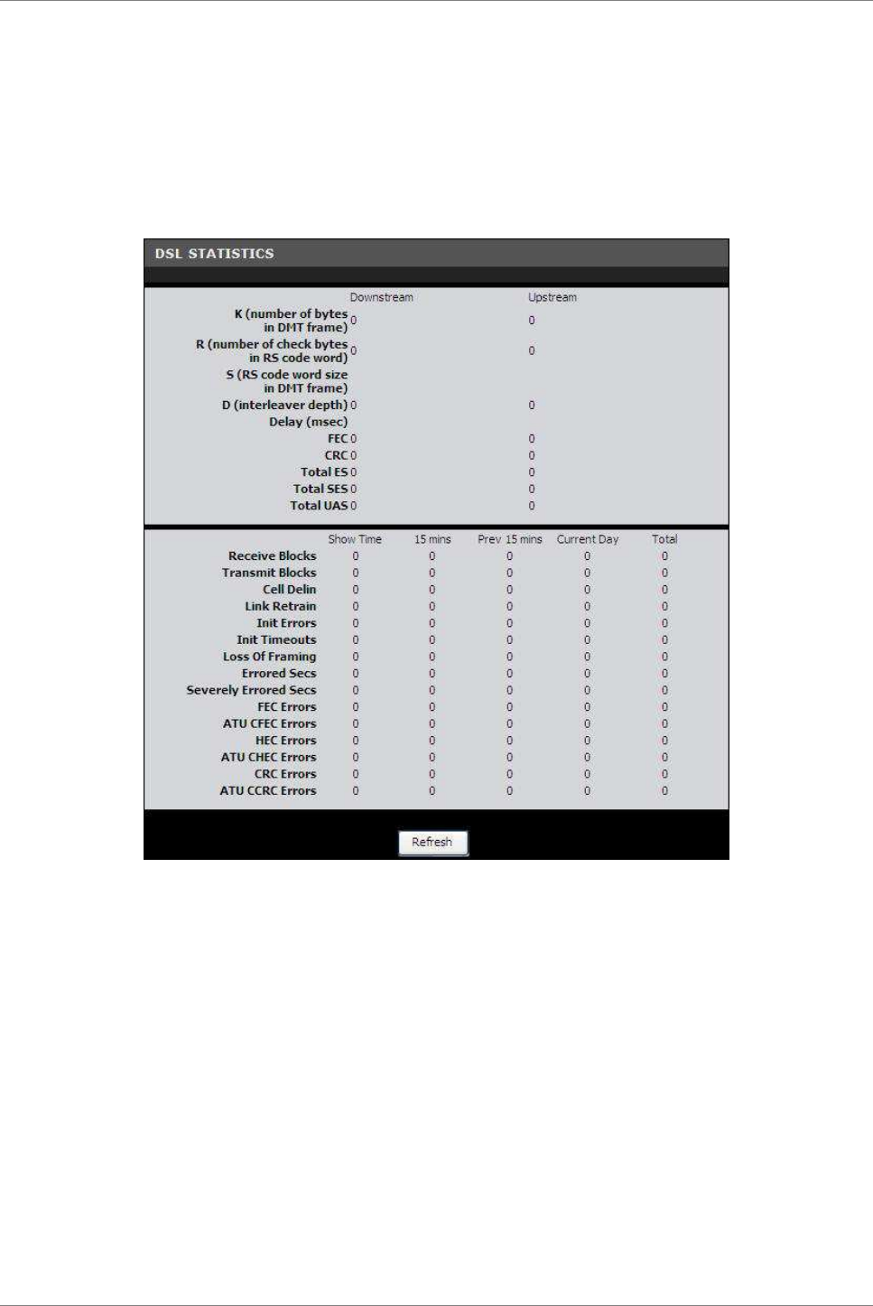
Status
TRENDnet DSLR-2001N
100
Statistics > DSL Statistics
This page displays the transmission and reception statistics of
the DSL line.
To access the DSL Statistics page, click STATUS > Statistics > DSL
Statistics or click the DSL Statistics button.
Click the Refresh button to refresh the information.

Appendix
TRENDnet DSLR-2001N
101
Appendix
A. Regulatory & Safety Information
Wireless LAN, Health and Authorization
Radio frequency electromagnetic energy is emitted from Wireless
LAN devices. The energy levels of these emissions however are far
much less than the electromagnetic energy emissions from wireless
devices like for example mobile phones. Wireless LAN devices are
safe for use frequency safety standards and recommendations. The
use of Wireless LAN devices may be restricted in some situations
or environments for example:
•
Onboard airplanes, or
•
In an explosive environment, or
•
In case the interference risk to other devices or services is
perceived or identified as harmful
In case the policy regarding the use of Wireless LAN devices in
specific organizations or environments (e.g. airports, hospitals,
chemical/oil/gas industrial plants, private buildings etc.) is not
clear, please ask for authorization to use these devices prior to
operating the equipment.
Disclaimers
Installation and use of this Wireless LAN device must be in strict
accordance with the instructions included in the user
documentation provided with the product. Any changes or
modifications made to this device that are not expressly approved
by the manufacturer may void the user’s authority to operate the
equipment. The Manufacturer is not responsible for any radio or
television interference caused by unauthorized modification of
this device, of the substitution or attachment. Manufacturer and
its authorized resellers or distributors will assume no liability
for any damage or violation of government regulations arising from
failing to comply with these guidelines.

Appendix
TRENDnet DSLR-2001N
102
FCC (Federal Communications Commission)
Statement
This equipment has been tested and found to comply with the limits
for a Class B digital device, pursuant to Part 15 of the FCC Rules.
These limits are designed to provide reasonable protection against
harmful interference in a residential installation. This equipment
generates, uses and can radiate radio frequency energy and, if not
installed and used in accordance with the instructions, may cause
harmful interference to radio communications. However, there is
no guarantee that interference will not occur in a particular
installation. If this equipment does cause harmful interference
to radio or television reception, which can be determined by
turning the equipment off and on, the user is encouraged to try to
correct the interference by one of the following measures:
•
Reorient or relocate the receiving antenna.
•
Increase the separation between the equipment and receiver.
•
Connect the equipment into an outlet on a circuit different from
that to which the receiver is connected.
•
Consult the dealer or an experienced radio/TV technician for
help.
FCC Caution: Any changes or modifications not expressly approved
by the party responsible for compliance could void the user’s
authority to operate this equipment. This device complies with
Part 15 of the FCC Rules. Operation is subject to the following
two conditions:
1. This device may not cause interference, and
2. This device must accept any interference, including
interference that my cause undesired operation of this
device.
IMPORTANT NOTE:
FCC Radiation Exposure Statement:
This equipment complies with FCC radiation exposure limits set
forth for an uncontrolled environment. This equipment should be
installed and operated with minimum distance 20cm between the
radiator & your body.
This transmitter must not be co-located or operating in
conjunction with any other antenna or transmitter.
The availability of some specific channels and/or operational
frequency bands are country dependent and are firmware programmed
at the factory to match the intended destination. The firmware
setting is not accessible by the end user.

Appendix
TRENDnet DSLR-2001N
103

Appendix
TRENDnet DSLR-2001N
104
PART 68 statement
This equipment complies with Part 68 of FCC Rules and the
requirements adopted by the ACTA.. On the bass unit of this
equipment is a label that contains, among other information, a
product identifier in the format US: CAMDL02BDSLR2001N
. If requested, this number must be provided to the telephone
company. The REN for this product is part of the product
identifier that has the format US: CAMDL02BDSLR2001N
. The digits represented by 01 are the REN without a decimal point.
The REN is useful to determine the quantity of devices you may
connect to your telephone line and still have those devices ring
when your telephone number is called. In most, but not all areas,
the sum of the REN of all devices connected to one line should not
exceed five (5.0). To be certain of the number of devices you may
connect to your line, as determined by the REN, you should contact
your local telephone company to determine the maximum REN for your
calling area.
If your equipment causes harm to the telephone network, the
telephone company may discontinue your service temporarily. If
possible, they will notify you in advance. If advance notice is
not practical, you will be notified as soon as possible. You will
be informed of your right to file a complaint with the FCC. Your
telephone company may make changes in its facilities, equipment,
operations or procedures that could affect the proper functioning
of your equipment. If they do, you will be notified in advance to
give you an opportunity to maintain uninterrupted telephone
service.
If you experience trouble with this telephone equipment, please
contact the following address and phone number for information on
obtaining service or repairs:
The telephone company may ask that you disconnect this equipment
from the network until the problem has been corrected or until you
are sure that the equipment is not malfunctioning.
This equipment may not be used on coin service provided by the
telephone company. Connection to party lines is subject to state
tariffs.
Contact information for service center in case of problems as
below:
Company: TRENDnet, Inc.
Address: 20675 Manhattan Place, Torrance, CA90501 U.S.A
Tel: (310)961-5500 Fax: (310)961-5511

Appendix
TRENDnet DSLR-2001N
105
CE statement
Europe – EU Declaration of Conformity
This device complies with the essential requirements of the R&TTE
Directive 1999/5/EC. The following test methods have been applied
in order to prove presumption of conformity with the essential
requirements of the R&TTE Directive 1999/5/EC:
EN60950-1: 2006
Safety of Information Technology Equipment
EN 50385: 2002
Product standard to demonstrate the compliance of radio base
stations and fixed terminal stations for wireless
telecommunication systems with the basic restrictions or the
reference levels related to human exposure to radio frequency
electromagnetic fields (110MHz - 40 GHz) - General public
EN 300 328 V1.7.1 (2006-10)
Electromagnetic compatibility and Radio spectrum Matters (ERM);
Wideband transmission systems; Data transmission equipment
operating in the 2,4 GHz ISM band and using wide band modulation
techniques; Harmonized EN covering essential requirements under
article 3.2 of the R&TTE Directive
EN 301 489-1 V1.8.1 (2008-04)
Electromagnetic compatibility and Radio Spectrum Matters (ERM);
ElectroMagnetic Compatibility (EMC) standard for radio equipment
and services; Part 1: Common technical requirements
EN 301 489-17 V2.1.1(2009-05)
Electromagnetic compatibility and Radio spectrum Matters (ERM);
ElectroMagnetic Compatibility (EMC) standard for radio equipment
and services; Part 17: Specific conditions for 2,4 GHz wideband
transmission systems , 5 GHz high performance RLAN equipment and
5,8GHz Broadband Data Transmitting Systems.
This device is a 2.4 GHz wideband transmission system
(transceiver), intended for use in all EU member states and EFTA
countries, except in France and Italy where restrictive use
applies.
In Italy the end-user should apply for a license at the national
spectrum authorities in order to obtain authorization to use the
device for setting up outdoor radio links and/or for supplying
public access to telecommunications and/or network services.
This device may not be used for setting up outdoor radio links in
France and in some areas the RF output power may be limited to 10
mW EIRP in the frequency range of 2454 – 2483.5 MHz. For detailed
information the end-user should contact the national spectrum
authority in France.

Appendix
TRENDnet DSLR-2001N
106

Appendix
TRENDnet DSLR-2001N
107
Česky [Czech] TRENDnet tímto prohlašuje, že tento DSLR-2001N je ve shodě se
základními požadavky a dalšími příslušnými ustanoveními směrnice
1999/5/ES.
Dansk [Danish] Undertegnede TRENDnet erklærer herved, at følgende udstyr DSLR-2001N
overholder de væsentlige krav og øvrige relevante krav i direktiv
1999/5/EF.
Deutsch
[German]
Hiermit erklärt TRENDnet , dass sich das Gerät DSLR-2001N in
Übereinstimmung mit den grundlegenden Anforderungen und den übrigen
einschlägigen Bestimmungen der Richtlinie 1999/5/EG befindet.
Eesti
[Estonian]
Käesolevaga kinnitab TRENDnet seadme DSLR-2001N vastavust direktiivi
1999/5/EÜ põhinõuetele ja nimetatud direktiivist tulenevatele
teistele asjakohastele sätetele.
English Hereby, TRENDnet , declares that this DSLR-2001N is in compliance
with the essential requirements and other relevant provisions of
Directive 1999/5/EC.
Español
[Spanish]
Por medio de la presente TRENDnet declara que el DSLR-2001N cumple
con los requisitos esenciales y cualesquiera otras disposiciones
aplicables o exigibles de la Directiva 1999/5/CE.
Ελληνική [Greek] ΜΕ ΤΗΝ ΠΑΡΟΥΣΑ TRENDnet ∆ΗΛΩΝΕΙ ΟΤΙDSLR-2001N ΣΥΜΜΟΡΦΩΝΕΤΑΙ
ΠΡΟΣ ΤΙΣ ΟΥΣΙΩ∆ΕΙΣ ΑΠΑΙΤΗΣΕΙΣ ΚΑΙ ΤΙΣ ΛΟΙΠΕΣ ΣΧΕΤΙΚΕΣ ∆ΙΑΤΑΞΕΙΣ ΤΗΣ
Ο∆ΗΓΙΑΣ 1999/5/ΕΚ.
Français
[French]
Par la présente TRENDnet déclare que l'appareil DSLR-2001N est
conforme aux exigences essentielles et aux autres dispositions
pertinentes de la directive 1999/5/CE.
Italiano
[Italian]
Con la presente TRENDnet dichiara che questo DSLR-2001N è conforme
ai requisiti essenziali ed alle altre disposizioni pertinenti
stabilite dalla direttiva 1999/5/CE.
Latviski
[Latvian]
Ar šo TRENDnet deklarē, ka DSLR-2001N atbilst Direktīvas 1999/5/EK
būtiskajām prasībām un citiem ar to saistītajiem noteikumiem.
Lietuvių
[Lithuanian]
Šiuo TRENDnet deklaruoja, kad šis DSLR-2001N atitinka esminius
reikalavimus ir kitas 1999/5/EB Direktyvos nuostatas.
Nederlands
[Dutch]
Hierbij verklaart TRENDnet dat het toestel DSLR-2001N in
overeenstemming is met de essentiële eisen en de andere relevante
bepalingen van richtlijn 1999/5/EG.
Malti [Maltese]
Hawnhekk, TRENDnet , jiddikjara li dan DSLR-2001N jikkonforma mal-
ħtiġijiet essenzjali u ma provvedimenti oħrajn relevanti li hemm fid-
Dirrettiva 1999/5/EC.
Magyar
[Hungarian]
Alulírott, TRENDnet nyilatkozom, hogy a DSLR-2001N megfelel a
vonatkozó alapvetõ követelményeknek és az 1999/5/EC irányelv egyéb
elõírásainak.
Polski [Polish]
Niniejszym TRENDnet oświadcza, że DSLR-2001N jest zgodny z
zasadniczymi wymogami oraz pozostałymi stosownymi postanowieniami
Dyrektywy 1999/5/EC.
Português
[Portuguese]
TRENDnet declara que este DSLR-2001N está conforme com os requisitos
essenciais e outras disposições da Directiva 1999/5/CE.
Slovensko
[Slovenian]
TRENDnet izjavlja, da je ta DSLR-2001N v skladu z bistvenimi
zahtevami in ostalimi relevantnimi določili direktive 1999/5/ES.
Slovensky TRENDnet týmto vyhlasuje, že DSLR-2001N spĺňa základné požiadavky a

Appendix
TRENDnet DSLR-2001N
108
[Slovak] všetky príslušné ustanovenia Smernice 1999/5/ES.
Suomi [Finnish]
TRENDnet vakuuttaa täten että DSLR-2001N tyyppinen laite on
direktiivin 1999/5/EY oleellisten vaatimusten ja sitä koskevien
direktiivin muiden ehtojen mukainen.
Svenska
[Swedish]
Härmed intygar TRENDnet att denna DSLR-2001N står I överensstämmelse
med de väsentliga egenskapskrav och övriga relevanta bestämmelser som
framgår av direktiv 1999/5/EG.

Appendix
TRENDnet DSLR-2001N
109
B. Specifications
General
Standards
Compliant with ADSL standards: ANSI T1.413 Issue2,
G.992.1 (G.dmt, Annex A), G.992.2 (G.lite)
Compliant with ADSL2 standard: G.992.3 (G.dmt.bis)
Compliant with ADSL2+ standard: G.992.5 Annex A
IEEE 802.11b & 802.11g & 802.11n Wireless LAN
IEEE 802.3u 10/100Base TX Fast Ethernet
Protocol
WLAN:
CSMA/CA with ACK
ATM & PPP:
VC and LLC Multiplexing, Bridged/Routed Ethernet
over ATM (RFC1483/2684), OAM F4/F5 loop-back, PPP
over ATM (RFC2364), PPP over Ethernet (RFC2516),
ATM TrafficShaping QoS(UBR, CBR, rt-VBR, nrt-VBR)
LAN/WAN Network:
TCP/IP, NAT, HTTP, DHCP Server/Relay/Client, DDNS,
DNS Proxy
Modulation
Schemes DBPSK/DQPSK/CCK/OFDM, BPSK/QPSK/16-QAM/64-QAM
Transmission
Rate
802.11n mode: up to 300Mbps
802.11g mode: up to 54Mbps
802.11b mode: up to 11Mbps
Ethernet: 10Mbps (half duplex), 20Mbps (full-
duplex)
Fast Ethernet: 100Mbps (half duplex), 200Mbps
(full- duplex)
Receiver
Sensitivity
802.11n: -64dBm typical @ 300Mbps
802.11g: -65dBm typical @ 54Mbps
802.11b: -80dBm typical @ 11Mbps
TX Power
(Average
power)
27dBm
Frequency
Range 2412 ~ 2484 MHz ISM band (channels 1~14)
Modulation
Schemes DBPSK/DQPSK/CCK/OFDM

Appendix
TRENDnet DSLR-2001N
110
Security 64/128-bits WEP Encryption; WPA, WPA2, WPA-TKIP,
WPA2-AES, WPS, MAC address filtering
Firewall
Security
NAT firewall, Stateful Packet Inspection (SPI),
Packet Filtering (IP, MAC Domain, Keyword),
Management Access Control for LAN/WAN
Management Web-based Configuration, Command Line Interface
(CLI) via Telnet, TR-069 Remote Management, IGMP
v1/v2 Support, SW upgrade
Channels
USA : Channel 1~11
Europe : Channel 1~13
Japan : Channel 1 ~14
Memory FLASH: 4MB
DDR SDRAM: 32MB
Antenna 2 x 2dBi external dipole antenna
Range
Coverage
Indoor: up to 100 meters
Outdoor: up to 300 meters
Physical and Environmental
Number of
Ports
LAN: 4 x 10/100Mbps Auto-MDIX Fast Ethernet ports
WAN: 1 x RJ11Port
Power Jack
LED Indicator Power, LAN 1~4 (Link/ACT), WLAN (Link/ACT), WPS,
ADSL, Internet
DC inputs 12VDC 1A
Power
Consumption 8.4watts (max)
Temperature Operating: 0°C ~ 40° C
Storage: -10°c ~ 70°C
Humidity Operating: 10% ~ 95%, RH, no condensation
Dimensions 201 x 115.8 x 37 mm (without antenna)
Certification FCC part 15, CE

Appendix
TRENDnet DSLR-2001N
111
C. Limited Warranty
TRENDnet warrants its products against defects in material and
workmanship, under normal use and service, for the following
lengths of time from the date of purchase.
DSLR-2001N – 3 Years Warranty
AC/DC Power Adapter, Cooling Fan, and Power Supply carry 1 year
warranty.
If a product does not operate as warranted during the applicable
warranty period, TRENDnet shall reserve the right, at its expense,
to repair or replace the defective product or part and deliver an
equivalent product or part to the customer. The repair/replacement
unit’s warranty continues from the original date of purchase. All
products that are replaced become the property of TRENDnet.
Replacement products may be new or reconditioned. TRENDnet does
not issue refunds or credit. Please contact the point-of-purchase
for their return policies.
TRENDnet shall not be responsible for any software, firmware,
information, or memory data of customer contained in, stored on,
or integrated with any products returned to TRENDnet pursuant to
any warranty.
There are no user serviceable parts inside the product. Do not
remove or attempt to service the product by any unauthorized
service center. This warranty is voided if (i) the product has
been modified or repaired by any unauthorized service center, (ii)
the product was subject to accident, abuse, or improper use (iii)
the product was subject to conditions more severe than those
specified in the manual.
Warranty service may be obtained by contacting TRENDnet within the
applicable warranty period and providing a copy of the dated proof
of the purchase. Upon proper submission of required documentation
a Return Material Authorization (RMA) number will be issued. An
RMA number is required in order to initiate warranty service
support for all TRENDnet products. Products that are sent to
TRENDnet for RMA service must have the RMA number marked on the
outside of return packages and sent to TRENDnet prepaid, insured
and packaged appropriately for safe shipment. Customers shipping
from outside of the USA and Canada are responsible for return
shipping fees. Customers shipping from outside of the USA are
responsible for custom charges, including but not limited to, duty,
tax, and other fees.
WARRANTIES EXCLUSIVE: IF THE TRENDNET PRODUCT DOES NOT OPERATE AS
WARRANTED ABOVE, THE CUSTOMER’S SOLE REMEDY SHALL BE, AT TRENDNET’S
OPTION, REPAIR OR REPLACE. THE FOREGOING WARRANTIES AND REMEDIES ARE

Appendix
TRENDnet DSLR-2001N
112
EXCLUSIVE AND ARE IN LIEU OF ALL OTHER WARRANTIES, EXPRESSED OR IMPLIED,
EITHER IN FACT OR BY OPERATION OF LAW, STATUTORY OR OTHERWISE, INCLUDING
WARRANTIES OF MERCHANTABILITY AND FITNESS FOR A PARTICULAR PURPOSE.
TRENDNET NEITHER ASSUMES NOR AUTHORIZES ANY OTHER PERSON TO ASSUME FOR
IT ANY OTHER LIABILITY IN CONNECTION WITH THE SALE, INSTALLATION
MAINTENANCE OR USE OF TRENDNET’S PRODUCTS.
TRENDNET SHALL NOT BE LIABLE UNDER THIS WARRANTY IF ITS TESTING AND
EXAMINATION DISCLOSE THAT THE ALLEGED DEFECT IN THE PRODUCT DOES NOT
EXIST OR WAS CAUSED BY CUSTOMER’S OR ANY THIRD PERSON’S MISUSE, NEGLECT,
IMPROPER INSTALLATION OR TESTING, UNAUTHORIZED ATTEMPTS TO REPAIR OR
MODIFY, OR ANY OTHER CAUSE BEYOND THE RANGE OF THE INTENDED USE, OR BY
ACCIDENT, FIRE, LIGHTNING, OR OTHER HAZARD.
LIMITATION OF LIABILITY: TO THE FULL EXTENT ALLOWED BY LAW TRENDNET ALSO
EXCLUDES FOR ITSELF AND ITS SUPPLIERS ANY LIABILITY, WHETHER BASED IN
CONTRACT OR TORT (INCLUDING NEGLIGENCE), FOR INCIDENTAL, CONSEQUENTIAL,
INDIRECT, SPECIAL, OR PUNITIVE DAMAGES OF ANY KIND, OR FOR LOSS OF
REVENUE OR PROFITS, LOSS OF BUSINESS, LOSS OF INFORMATION OR DATE, OR
OTHER FINANCIAL LOSS ARISING OUT OF OR IN CONNECTION WITH THE SALE,
INSTALLATION, MAINTENANCE, USE, PERFORMANCE, FAILURE, OR INTERRUPTION OF
THE POSSIBILITY OF SUCH DAMAGES, AND LIMITS ITS LIABILITY TO REPAIR,
REPLACEMENT, OR REFUND OF THE PURCHASE PRICE PAID, AT TRENDNET’S OPTION.
THIS DISCLAIMER OF LIABILITY FOR DAMAGES WILL NOT BE AFFECTED IF ANY
REMEDY PROVIDED HEREIN SHALL FAIL OF ITS ESSENTIAL PURPOSE.
Governing Law: This Limited Warranty shall be governed by the laws
of the state of California.
Some TRENDnet products include software code written by third party
developers. These codes are subject to the GNU General Public License
("GPL") or GNU Lesser General Public License ("LGPL").
Go to http://www.trendnet.com/gpl or http://www.trendnet.com Download
section and look for the desired TRENDnet product to access to the GPL
Code or LGPL Code. These codes are distributed WITHOUT WARRANTY and are
subject to the copyrights of the developers. TRENDnet does not provide
technical support for these codes. Please go to
http://www.gnu.org/licenses/gpl.txt or
http://www.gnu.org/licenses/lgpl.txt for specific terms of each license.
PWP05202009v2