Cameo Communications WLG2008B 54Mbps Wireless LAN Pocket Access Point User Manual WLG 2008
Cameo Communications Inc 54Mbps Wireless LAN Pocket Access Point WLG 2008
Contents
- 1. Manual Part1
- 2. Manual Part2
Manual Part1

i
54Mbps Wireless LAN
Pocket Access Point
USER MANUAL
Regulatory notes and statements
Wireless LAN, Health and Authorization for use
Radio frequency electromagnetic energy is emitted from Wireless LAN devices.
The energy levels of these emissions however are far much less than the
electromagnetic energy emissions from wireless devices like for example mobile
phones. Wireless LAN devices are safe for use frequency safety standards and
recommendations. The use of Wireless LAN devices may be restricted in some
situations or environments for example:
z On board of airplanes, or
z In an explosive environment, or
z In case the interference risk to other devices or services is perceived or
identified as harmful
In case the policy regarding the use of Wireless LAN devices in specific
organizations or environments (e.g. airports, hospitals, chemical/oil/gas industrial
plants, private buildings etc.) is not clear, please ask for authorization to use these
devices prior to operating the equipment.
Regulatory Information/disclaimers
Installation and use of this Wireless LAN device must be in strict accordance with
the instructions included in the user documentation provided with the product. Any
changes or modifications made to this device that are not expressly approved by
the manufacturer may void the user’s authority to operate the equipment. The
Manufacturer is not responsible for any radio or television interference caused by
unauthorized modification of this device, of the substitution or attachment.
Manufacturer and its authorized resellers or distributors will assume no liability for
any damage or violation of government regulations arising from failing to comply
with these guidelines.
Federal Communication Commission Interference Statement
This equipment has been tested and found to comply with the limits for a Class B
digital device, pursuant to Part 15 of the FCC Rules. These limits are designed to
provide reasonable protection against harmful interference in a residential
installation. This equipment generates, uses and can radiate radio frequency energy
and, if not installed and used in accordance with the instructions, may cause
harmful interference to radio communications. However, there is no guarantee
that interference will not occur in a particular installation. If this equipment does
cause harmful interference to radio or television reception, which can be
determined by turning the equipment off and on, the user is encouraged to try to
correct the interference by one of the following measures:
- Reorient or relocate the receiving antenna.
- Increase the separation between the equipment and receiver.
- Connect the equipment into an outlet on a circuit different from that
to which the receiver is connected.
- Consult the dealer or an experienced radio/TV technician for help.
FCC Caution: Any changes or modifications not expressly approved by the party
responsible for compliance could void the user's authority to operate this
equipment.
This device complies with Part 15 of the FCC Rules. Operation is subject to the
following two conditions: (1) This device may not cause harmful interference, and
(2) this device must accept any interference received, including interference that
may cause undesired operation.
IMPORTANT NOTE:
FCC Radiation Exposure Statement:
This equipment complies with FCC radiation exposure limits set forth for an
uncontrolled environment. This equipment should be installed and operated with
minimum distance 20cm between the radiator & your body.
This transmitter must not be co-located or operating in conjunction with any other
antenna or transmitter.
The availability of some specific channels and/or operational frequency bands are
country dependent and are firmware programmed at the factory to match the
intended destination. The firmware setting is not accessible by the end user.
Safety Information
Your device contains a low power transmitter. When device is transmitted it sends
out radio frequency (RF) signal.
CAUTION: To maintain compliance with FCC’s RF exposure guidelines, this
equipment should be installed and operated with minimum distance 20cm between
the radiator and your body. Use on the supplied antenna. Unauthorized antenna,
modification, or attachments could damage the transmitter and may violate FCC
regulations.
The antenna(s) used for this transmitter must be installed to provide a separation
distance of at least 20 cm from all persons and must not be co-located or operating
in conjunction with any other antenna or transmitter.
CE Mark Warning
This is a Class B product. In a domestic environment, this product may cause
radio interference, in which case the user may be required to take adequate
measures.

Protection requirements for health and safety – Article 3.1a
Testing for electric safety according to EN 60950 has been conducted. These
are considered relevant and sufficient.
Protection requirements for electromagnetic compatibility –
Article 3.1b
Testing for electromagnetic compatibility according to EN 301 489-1, EN 301
489-17 and EN 55024 has been conducted. These are considered relevant and
sufficient.
Effective use of the radio spectrum – Article 3.2
Testing for radio test suites according to EN 300 328-2 has been conducted.
These are considered relevant and sufficient.
CE in which Countries where the product may be used freely:
Germany, UK, Italy, Spain, Belgium, Netherlands, Portugal, Greece, Ireland,
Denmark, Luxembourg, Austria, Finland, Sweden, Norway and Iceland.
France: except the channel 10 through 13, law prohibits the use of other
channels.

1
Contents
1. Overview ....................................................................................................1
1.1 Product Feature..........................................................................................1
1.2 System Requirements ...............................................................................1
1.3 How to switch within 3 modes ..................................................................1
2. Getting Start with AP mode ......................................................................2
2.1 Know the 54Mbps Wireless Network Access Point ..............................2
2.2 Connect to the 54Mbps Wireless Network Access Point .....................2
2.3 Quick Setup with Wizard...........................................................................3
2.3.1 Access the Setting Menu...................................................................3
2.3.2 Setup with Wizard...............................................................................4
3. Configuration the AP Mode ......................................................................7
3.1 Status ...........................................................................................................7
3.2 Basic Setting ...............................................................................................8
3.3 IP Setting ...................................................................................................10
3.4 Advanced Setting .....................................................................................11
3.5 Security ......................................................................................................13
3.6 Tools ...........................................................................................................14
4. Getting Start with Client mode ...............................................................16
4.1 Know the Wireless Ethernet Adapter ....................................................16
4.2 Connect to the Wireless Ethernet Adapter...........................................16
4.2.1 Access the Setting Menu.....................................................................17
5. Configuration Wireless Ethernet Client mode ......................................19
5.1 Status..........................................................................................................19
5.2 Basic Setting..............................................................................................20
5.3 IP Setting ...................................................................................................22
5.4 Advanced Setting .....................................................................................23
5.5 Security ......................................................................................................25
5.6 Tools ...........................................................................................................26
6. Getting Start with Wireless Router ........................................................27
6.1 Know the 802.11g Wireless Router .......................................................27
6.2 Connect to the 802.11g Wireless Router..............................................27
6.2.1 Access the Setting Menu.................................................................27
6.2.2 Quick Setup with Wizard................................................................29
7. Configuration Wireless Router through WEB Browser........................34
7.1 LAN Setting ...............................................................................................34
7.1.1 LAN & DHCP Server.....................................................................34

2
7.1.2 WAN ...............................................................................................35
7.1.3 Password.........................................................................................39
7.1.4 Time................................................................................................40
7.2 Wireless ...................................................................................................41
7.2.1 Basic................................................................................................41
7.2.2 WEP................................................................................................42
7.2.3 Advanced ........................................................................................43
7.3 Status .......................................................................................................44
7.3.1 Device Information.........................................................................44
7.3.2 Log..................................................................................................45
7.3.3 Log Setting......................................................................................46
7.3.4 Statistic............................................................................................47
7.3.5 Wireless...........................................................................................47
7.4 Routing.......................................................................................................48
7.4.1 Static ...............................................................................................48
7.4.2 Dynamic..........................................................................................49
7.4.3 Routing Table..................................................................................50
7.5 Access........................................................................................................51
7.5.1 MAC Filters....................................................................................51
7.5.2 Protocol Filter .................................................................................52
7.5.3 IP Filter ...........................................................................................53
7.5.4 Virtual Server..................................................................................54
7.5.5 Special AP.......................................................................................55
7.5.6 DMZ................................................................................................56
7.5.7 Firewall Rule...................................................................................57
7.6 Management .............................................................................................58
7.6.1 Remote Management......................................................................58
7.7.1 Restart.............................................................................................59
7.7.2 Settings............................................................................................60
7.7.3 Firmware.........................................................................................61
7.7.4 Ping Test..........................................................................................61
Technical Specifications ................................................................................62

1
1. Overview
1.1 Product Feature
● 3-in-1 function build-in with easily accessible hot-key switch, including
Access Point, Access Point Client and Wireless Router. It’s also the
smallest networking device in the market.
● Low power consumption <less than 460 mA>, and support USB power
adapter which provides the best mobility.
● Compliance with IEEE 802.11g and 802.11b standards
● Achieving data rate up to 54Mbps for 802.11g and 11Mps for 802.11b with
wide range coverage
● Strong network security with WEP encryption, WPA-PSK and WPA2-PSK
function.
● Quick and easy setup with Web-based management utility.
1.2 System Requirements
● Windows 98SE, Millennium Edition (ME), 2000 and XP operating systems
● Microsoft Internet Explorer 5.5 or higher
● At least one RJ-45 Ethernet network adapter installed.
1.3 How to switch within 3 modes
● 3 modes are AP, Client and wireless RT.
● Switch to the mode user wants with the hot key, then re-plug the power.
● Few seconds later, the device will reboot automatically to the mode user
wants.
● For AP mode, please use 192.168.1.1 as the default IP to configure the
settings.
● For Client mode, please use 192.168.1.50 as the default IP to configure
the settings.
● For Wireless RT mode, please use 192.168.1.1 as the default IP to
configure the settings, note that the settings must through the wireless
connection, instead of RJ45 cable.
2
2. Getting Start with AP mode
2.1 Know the 54Mbps Wireless Network Access Point
Ports:
● Power Receptor
● Reset Button
● RJ-45 Ethernet Port
Cross-over cable is required to connect to computer directly
LEDs:
● Power LED: ON when the unit is powered up
● LAN LED: ON indicates LAN connection; BLINK indicates LAN activity
● WLAN LED: ON indicates WLAN is working; BLINK indicates wireless
activity.
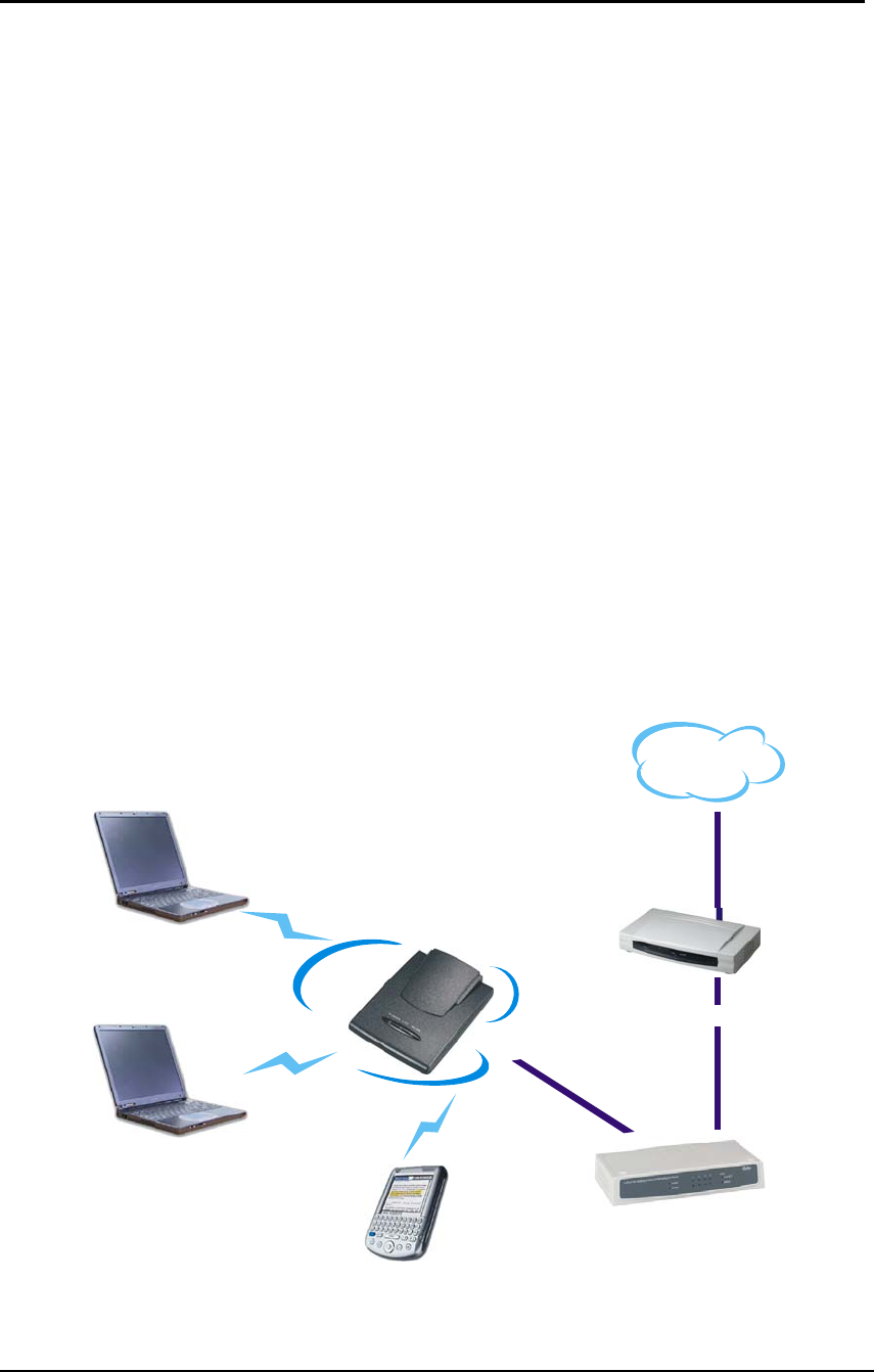
2.2 Connect to the 54Mbps Wireless Network Access Point
Build the Infrastructure Mode
SOHO Router
ADSL/Cable Modem
Wireless Station
Internet
Mobile PD
A
Wireless Station
Wireless Network
3
In order to setup an Infrastructure of a wireless network such as the example
shown above, user will need the following:
1. A broadband Internet connection.
2. ADSL or Cable modem provided by ISP as part of the broadband connection
installation.
3. A Router that connects to the ADSL/Cable modem for Internet connection
sharing.
4. An Access Point to connect with the Router to form a wireless infrastructure
network.
5. Wireless clients equipped with wireless networking devices such as wireless
PC Card for wireless connection.
2.3 Quick Setup with Wizard
2.3.1 Access the Setting Menu
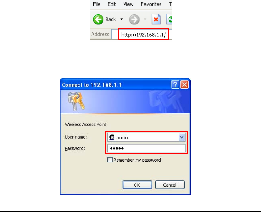
User could start to access the configuration menu anytime by opening a web
browser window and typing the IP address of this access point. The default IP
is 192.168.1.1.
The below window will popup. Please enter the user name and password.
Both of the default is “admin”.
4
Now, the main menu screen is popup.
2.3.2 Setup with Wizard
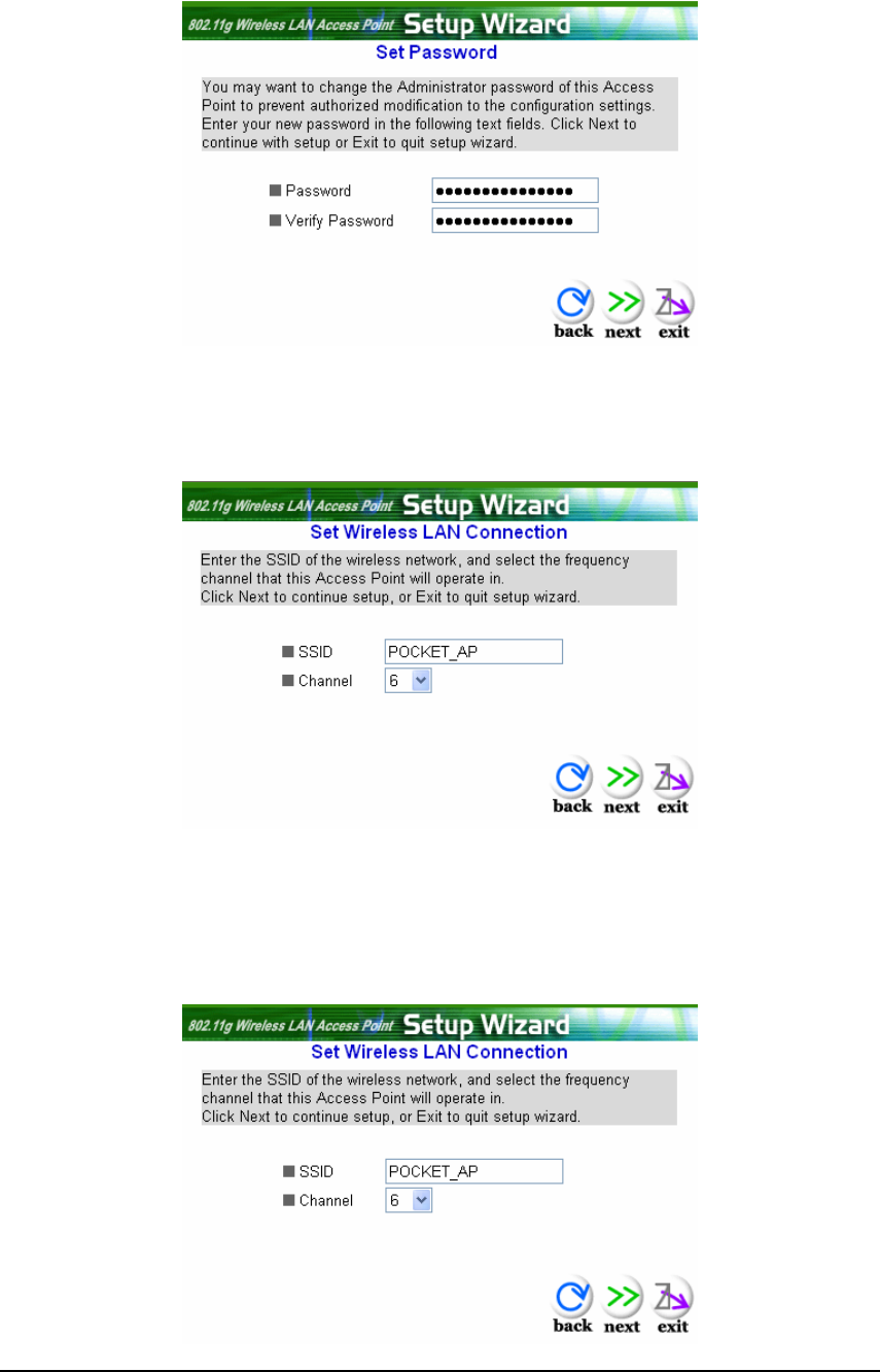
Setup wizard is provided as the part of the web configuration utility. User can
simply follow the step-by-step process to get Access Point configuration ready to
run in 4 easy steps by clicking on the “Wizard” button on the function menu. The
following screen will appear. Please click “Next” to continue.
5
Step 1: Set Password
User can change the password and then click “Next” to continue.
Step2: Set WLAN Connection
Please type the name of SSID and select the channel. Then, click “Next” to
continue.
Step 3: Set Wireless LAN Connection
If user doesn’t want to use “default” as the SSID, user can change SSID here.
User can also choose different channel to avoid noise coming from other
wireless networking devices. Please click “Next” to continue.
6
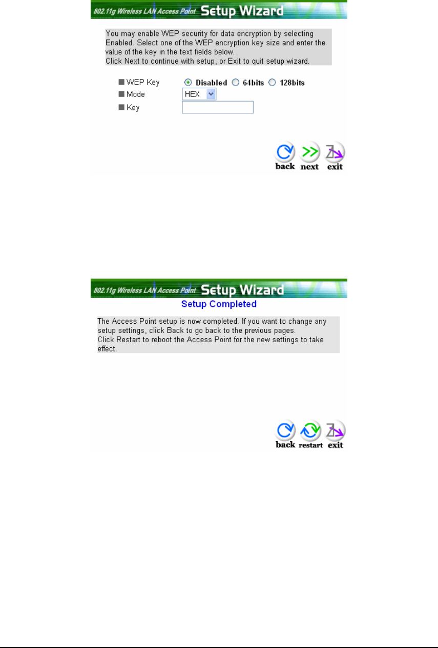
Step 4: Set WEP Encryption
If user wants to enable WEP, please click “Enabled”. Then, select the key size
of WEP encryption and enter the key value in the key text box. Please click
“Next” to continue.
Step 5: Setup Completed
The Setup wizard is now completed. The new settings will be effective after the
Access Point restarted. Please click “Restart” to reboot the Access Point. If
user does not want to make any changes, please click “exit” to quit without any
changes. User also can go back to modify the setting by clicking “Back”.
7
3. Configuration the AP Mode
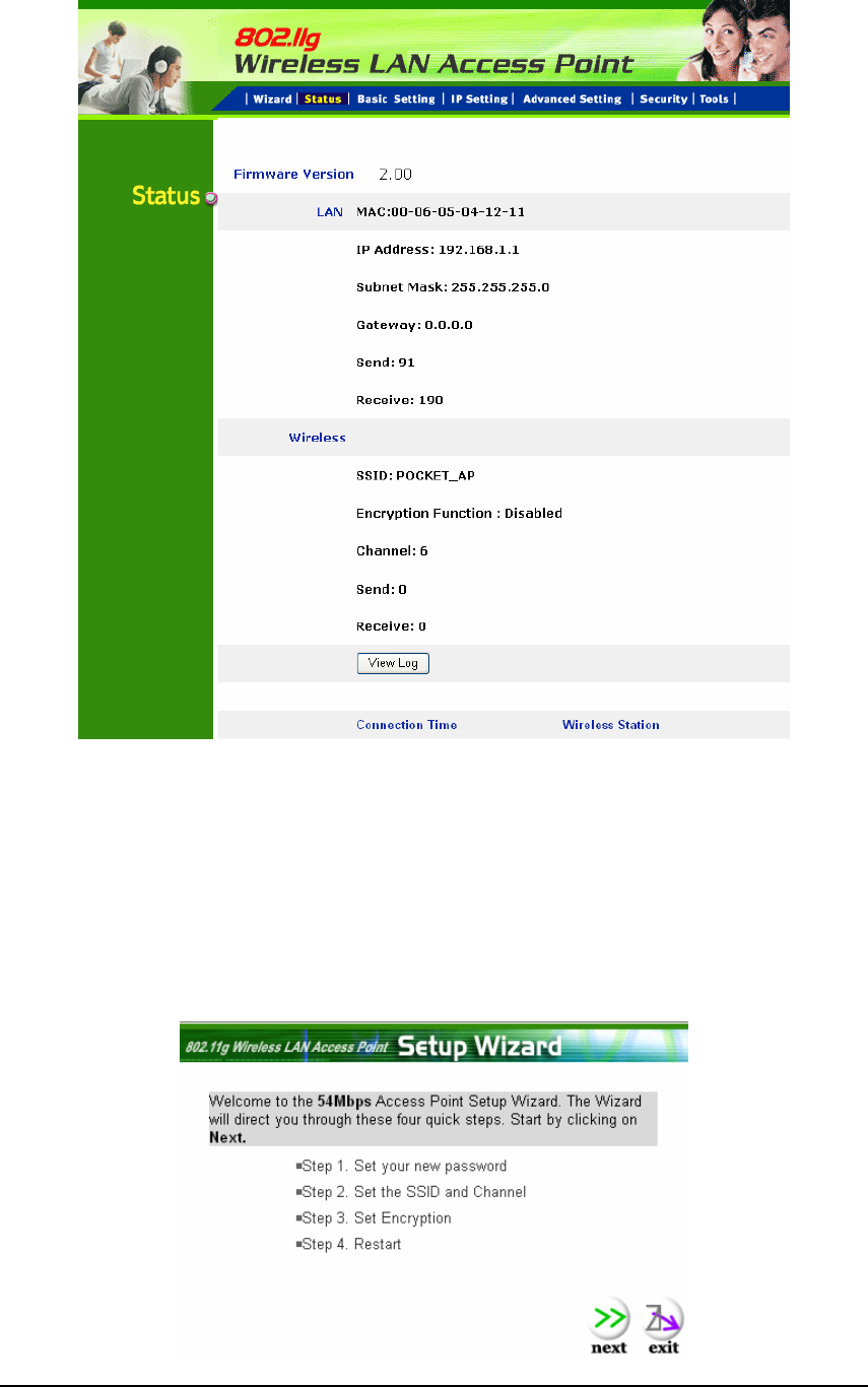
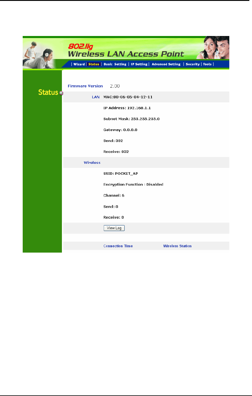
3.1 Status
This page as below shows the following information.
Firmware Version: Shows the current firmware version.
LAN: Shows the Mac address, IP address (default: 192.168.1.1), Subnet Mask,
Gateway Address. The current LAN traffic calculated in terms of number of
packets sent and received by AP through wired connection is also displayed.
Wireless: Shows the Mac address, current ESSID, the status of Encryption
Function (Enable or Disable), the current using channel. The current wireless
traffic calculated in terms of number of packets sent and received by AP through
wireless communication is also displayed.
8
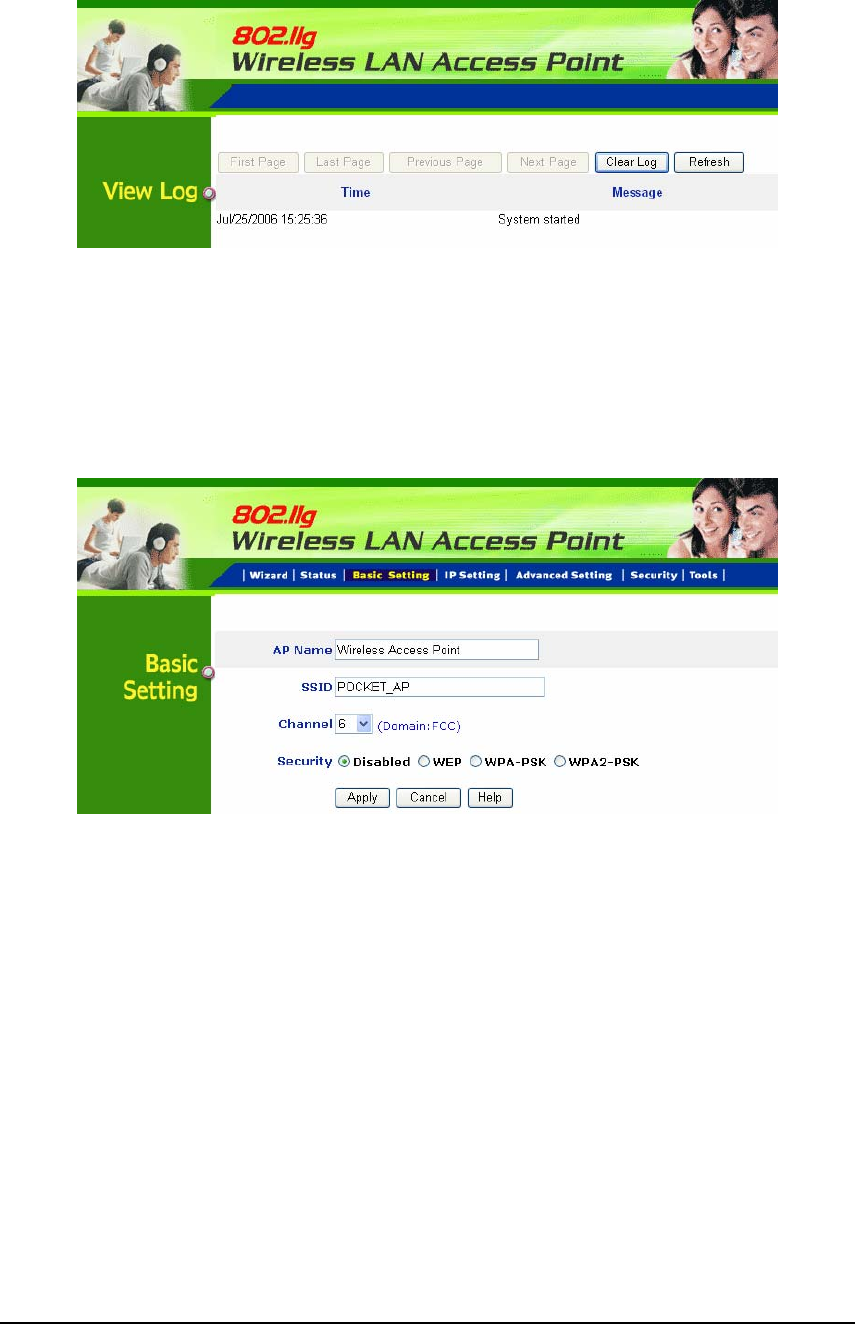
View Log: Once clicked, the page will change to login page. The login page
records every event and the time that it happens.
User may clear the entries recorded in the log by clicking the “Clear Log” button,
and refresh the screen to show the latest log entries by clicking the “Refresh”
button.
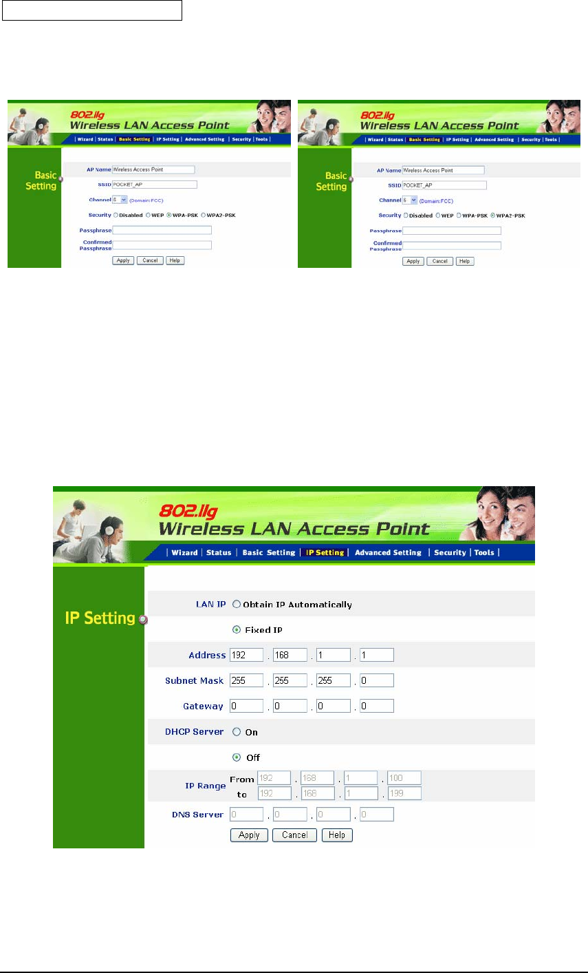
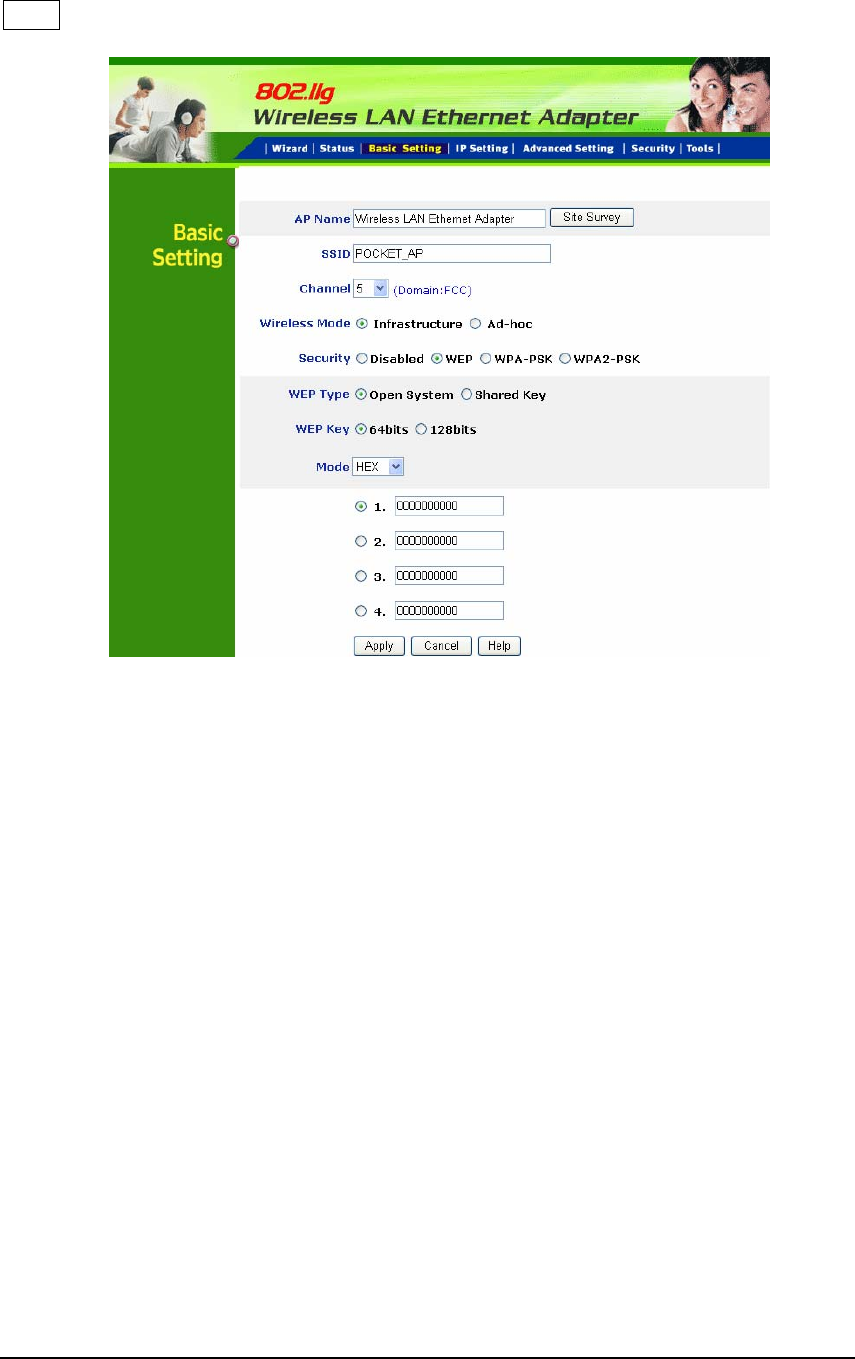
3.2 Basic Setting
This is the page allow user to change the access point settings.
AP Name: The name of the AP, which can be used to identify the Access Point
among the all the Access Points in the wireless network.
SSID: Service Set Identifier, which is a unique name shared among all clients
and nodes in a wireless network. The SSID must be identical for each clients
and nodes in the wireless network.
Channel: The channel that AP will operate in. User can select the channel
range from 1 to 11 for North America (FCC) domain, 1 to 13 for European (ETSI)
domain and 1 to 14 for Japanese domain. (We only provide FCC domain for
North America, ETSI domain for European)
9
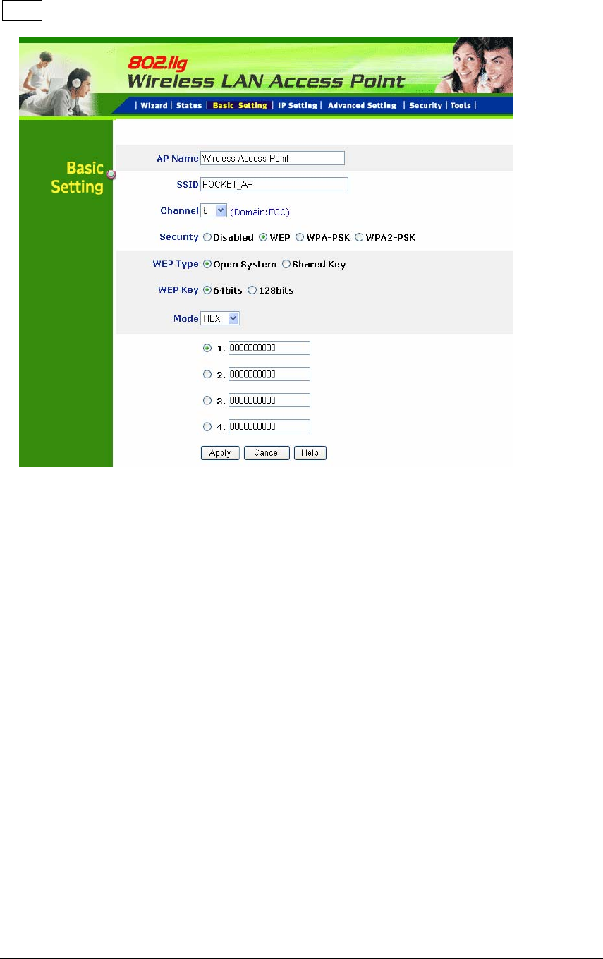
Security: There are four options: Disable; WEP; WPA-PSK and WPA2-PSK.
WEP
WEP Type: Open System allows public access to the router via wireless
communications; Shared Key requires the user to set a WEP key to exchange
data with other wireless clients that have the same WEP key.
WEP Key: Select the level of encryption from the drop-down list. The AP
supports, 64- and 128-bit key length encryption.
Mode: Select the key mode in ASCII or HEX format.
Key 1 ~ Key 4: Enables user to create an encryption scheme for Wireless
LAN transmissions. Manually enter a set of values for each key. Select a key
to use by clicking the radio button next to the key.
Apply: For the changes made to any of the items above to be effective, click
“Apply”. The new settings are now been saved to Access Point and will be
effective once the Access Point restarts.
Note: When WEP security is enabled, all the wireless clients that wish to
connect to the Access Point must also have WEP enabled with the identical
WEP Key value entered.
10
WPA-PSK / WPA2-PSK
If WPA-PSK or WPA2-PSK is selected, please set the PSK key in the pass
phrase field. The length should be 8 characters at least.
Note: Once WPA-PSK / WPA2-PSK function enables, it will take some time to
make the setting active.
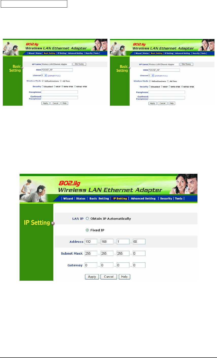
3.3 IP Setting
This page allows user to configure the IP and DHCP settings of the Access
Point.
The default IP address of this access point is 192.168.1.1 with the subnet mask
of 255.255.255.0. User can type in other values for IP Address, Subnet Mask
and Gateway and click “Apply” button for the changes to be effective.
11
User can also set the Access Point to obtain the IP from a DHCP server, but it is
not recommended. Select the option “Obtain IP Automatically” and click
“Apply” button for the changes to be effective.
DHCP Server: It is not recommended to enable the DHCP Server if user has a
DHCP server running in LAN network because it probably will cause possible
the conflict of IP assignment. Enable the DHCP server function by selecting the
option “On”, and enter the IP range.
DNS Server: Type up to DNS IP address in the text boxes. Your ISP will provide
you with this information.
Click “Apply” for the changes to be effective
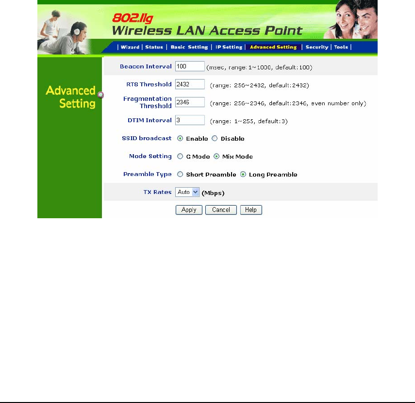
3.4 Advanced Setting
This page contains configurations for advanced users, which the change reflects
the wireless performance and operating modes.
Beacon Interval: To set the period of time in milliseconds that AP sends out a
beacon. Default is 100 milliseconds.
RTS Threshold: To set the size of RTS/CTS packet size. Default is 2432 bytes.
Fragmentation Threshold: To set the number of bytes used for the
fragmentation boundary for directed messages. Default is 2346 bytes.

12
DTIM Interval: This value indicates the interval of the Delivery Traffic Indication
Message (DTIM). A DTIM field is a countdown field informing clients of the
next window for listening to broadcast and multicast messages. When the
access point has buffered broadcast or multicast messages for associated
clients, it sends the next DTIM with a DTIM interval value. Access point clients
hear the beacons and awaken to receive the broadcast and multicast messages.
SSID Broadcast: While SSID Broadcast is enabled, all wireless clients will be
able to communicate with the access point. For secure purpose, user may
want to disable SSID broadcast to allow only those wireless clients with the AP
SSID to communicate with the access point.
Mode setting: 1) G mode- Only support 11g client to connect!
2) Mix mode- Support 11b&11g client to connect!
Preamble type: The usage of the preamble is to limit the packet size of the data
to transmit. It is recommended to choose the short preamble when the link
quality is bad, it is to prevent the wasting time of resending a long packet that is
lost.
TX Rates: User also can fix the transmission at specific data rate, if choose
“Auto” data rate, the AP will change the data rate to have the best receive or
transmit quality
13
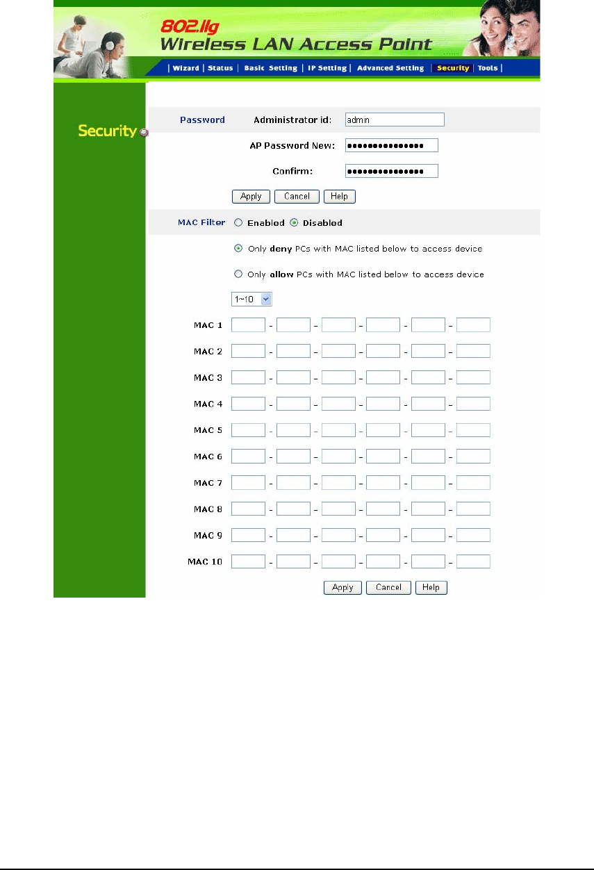
3.5 Security
This page is where user configures the security features supported by this
Access Point.
Administrator id: Allow you change the administrator user id.
Password: Allow you to change the new login password. Follow the steps
below:
1. Enter the new password in the “AP Password New:” field.
2. Enter the new password again in the “Confirm” field.
3. Click “Apply”
14
MAC Filter: MAC Filter function controls the MAC of the network devices that
are listed in this table for access authorization or denial. When MAC Filter is
enabled, by selecting the “Enabled” radio box, select one of two choices:
●Only deny PCs with MAC listed below to access device
●Only allow PCs with MAC listed below to access device
The maximum number of MAC addresses that can be stored is 50. You can
browse through the MAC address saved by selecting the drop-down box.
For any changes made in the security page, click “Apply” for the changes to be
effective.
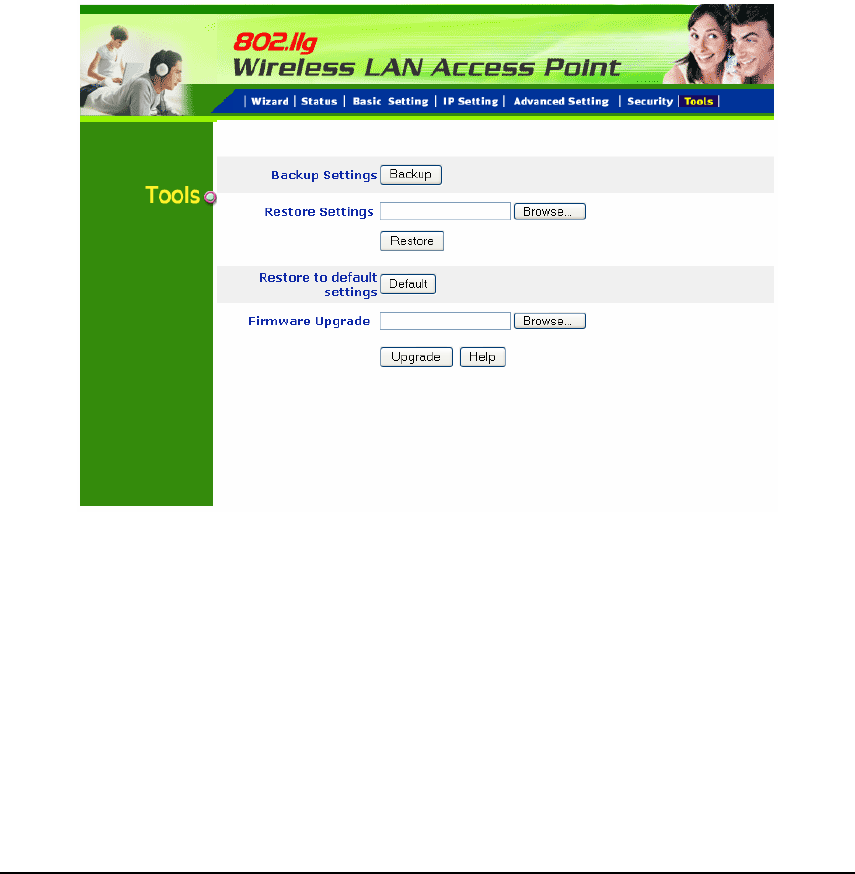
3.6 Tools
Four functions are provided in this page, Backup, Restore Settings, Restore
default settings and Firmware Upgrade.
Backup Settings: Click on “Backup” button, which will open a FileSave Dialog
box, where user gets to save all the current settings and configurations to a file.
Restore Settings: Click on the “Browse” button to open a FileOpen Dialog box,
where user gets to select the file, which saves previous settings and
configurations. Upon selecting the saved file, click “Restore” and complete the
restore process when the access point re-operates after it restarts.
Restore to default settings: Click on “Default” button to restore the access
point back to its manufacture default settings.

15
Firmware Upgrade: Click on the “Browse” button to open a FileOpen Dialog
box, where gets to select the firmware file, which download from the web for the
latest version. Upon selecting the firmware file, click “Upgrade” and complete
the firmware upgrade process when the Access Point re-operates after it
restarts.
16
4. Getting Start with Client mode
4.1 Know the Wireless Ethernet Adapter
Ports:
● Power Receptor
● Reset Button
● RJ-45 Ethernet Port
Cross-over cable is required to connect to computer directly
LEDs:
● Power LED: ON when the unit is powered up
● LAN LED: ON indicates LAN connection; BLINK indicates LAN activity
● WLAN LED: ON indicates WLAN is working; BLINK indicates wireless
activity.
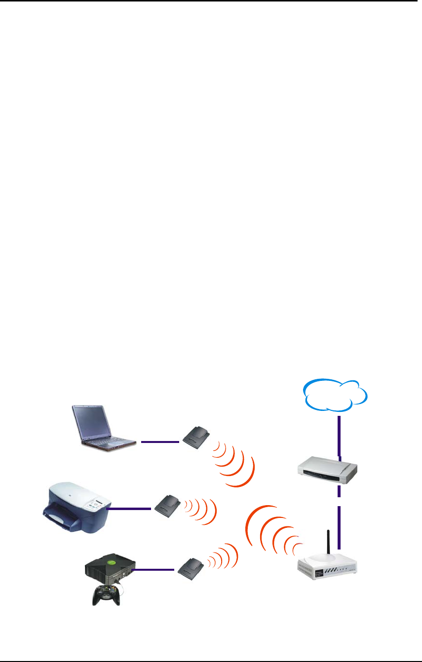
4.2 Connect to the Wireless Ethernet Adapter
This wireless Ethernet adapter transforms the Ethernet-enabled devices to
have the wireless function. The wireless Ethernet adapter enables wireless
communication over network. There are two examples shown as the below.
Infrastructure Mode:
WLAN AP Router /
ADSL/Cable Modem
Notebook PC
Printer
Came Consol
e
Internet
17
Ad-Hoc Mode:
Came Console Came Console
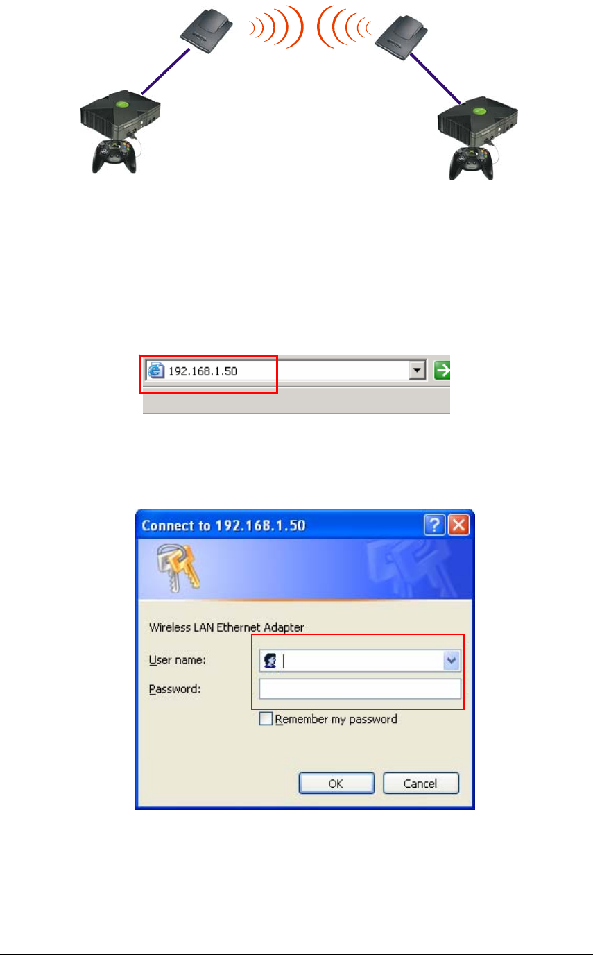
4.2.1 Access the Setting Menu
User could start to access the configuration menu anytime by opening a web
browser window by typing the IP address of this access point. The default IP is
192.168.1.50.
The below window will popup. Please enter the user name and password.
Both of the default is “admin”.

18
Now, the main menu screen is popup.
19
5. Configuration Wireless Ethernet
Client mode
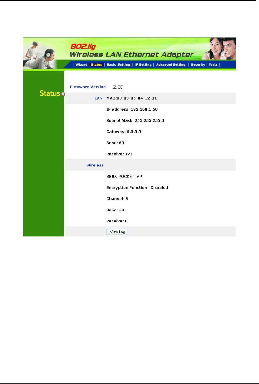
5.1 Status
This page as below shows the following information.
Firmware Version: Shows the current firmware version.
LAN: Shows the Mac address, IP address (default: 192.168.1.50), Subnet Mask,
Gateway Address. The current LAN traffic calculated in terms of number of
packets sent and received by AP through wired connection is also displayed.
Wireless: Shows the Mac address, current ESSID, the status of Encryption
Function (Enable or Disable), the current using channel. The current wireless
traffic calculated in terms of number of packets sent and received by AP through
wireless communication is also displayed.
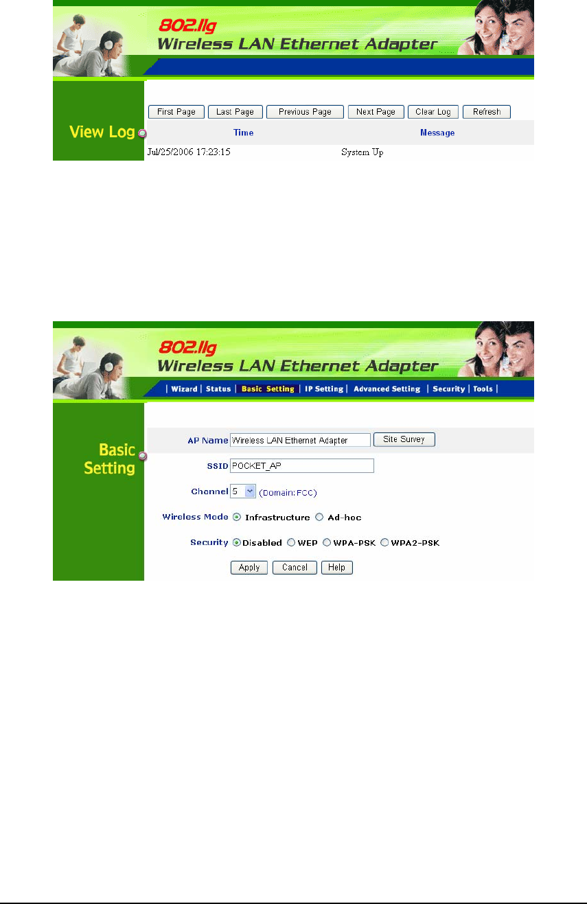
20
View Log: Upon clicked, the page will change to log page. The log page records
every event and the time that it happens.
User may clear the entries recorded in the log by clicking the “Clear Log” button,
and refresh the screen to show the latest log entries by clicking “Refresh”
button.
5.2 Basic Setting
This is the page allow to change the settings of access point.
AP Name: The name of the AP, which can be used to identify the Access Point
among the all the Access Points in the wireless network.
SSID: Service Set Identifier, which is a unique name shared among all clients
and nodes in a wireless network. The SSID must be identical for each clients
and nodes in the wireless network.
Channel: The channel that AP will operate in. User can select the channel
range of 1 to 11 for North America (FCC) domain, 1 to 13 for European (ETSI)
domain and 1 to 14 for Japanese domain.
Wireless Mode: Select the AP in client mode works for Infrastructure
application or Ad-hoc application.
21
Security: There are four options: Disable; WEP; WPA-PSK and WPA2-PSK.
WEP
WEP Type: Open System allows public access to the router via wireless
communications; Shared Key requires the user to set a WEP key to exchange
data with other wireless clients that have the same WEP key.
WEP Key: Select the level of encryption from the drop-down list. The AP
supports, 64- and 128-bit key length encryption.
Mode: Select the key mode in ASCII or HEX format.
Key 1 ~ Key 4: Enables user to create an encryption scheme for Wireless
LAN transmissions. Manually enter a set of values for each key. Select a key
to use by clicking the radio button next to the key.
Apply: For the changes made to any of the items above to be effective, click
“Apply”. The new settings are now been saved to Access Point and will be
effective once the Access Point restarts.
Note: When WEP security is enabled, all the wireless clients that wish to
connect to the Access Point must also have WEP enabled with the identical
WEP Key value entered.
22
WPA-PSK / WPA2-PSK
If WPA-PSK or WPA2-PSK is selected, please set the PSK key in the pass
phrase field. The length should be 8 characters at least.
Note: Once WPA-PSK / WPA2-PSK function enables, it will take some time to
make the setting active.
5.3 IP Setting
This page allows users to configure the IP and DHCP settings of the Pocket
Access Point.
The default IP address of the Pocket Access Point in Clint mode is
192.168.1.50 with the subnet mask of 255.255.255.0. User can type in other
values for IP Address, Subnet Mask and Gateway and click “Apply” button for
the changes to be effective.
User can also set the Pocket Access Point to obtain the IP from a DHCP server,
but it is not recommended. Select the option “Obtain IP Automatically” and
click “Apply” button for the changes to be effective.

23
5.4 Advanced Setting
This page contains configurations for advanced users, which the change reflects,
the wireless performance and operating modes.
Beacon Interval: To set the period of time in milliseconds that AP sends out a
beacon. Default is 100 milliseconds.
RTS Threshold: To set the size of RTS/CTS packet size. Default is 2432 bytes.
Fragmentation Threshold: To set the number of bytes used for the
fragmentation boundary for directed messages. Default is 2436 bytes.
DTIM Interval: This value indicates the interval of the Delivery Traffic Indication
Message (DTIM). A DTIM field is a countdown field informing clients of the
next window for listening to broadcast and multicast messages. When the
access point has buffered broadcast or multicast messages for associated
clients, it sends the next DTIM with a DTIM interval value. Access point clients
hear the beacons and awaken to receive the broadcast and multicast messages.

24
Preamble Type: Select Long or Short Preamble type. Preamble is a sequence
of bits transmitted at 1Mbps that allows the PHY circuitry to reach steady-state
demodulation and synchronization of bit clock and frame start. Two different
preambles and headers are defined: the mandatory supported Long Preamble
and header, which interoperates with the 1 Mbit/s and 2 Mbit/s DSSS
specification (as described in IEEE Std 802.11), and an optional Short Preamble
and header (as described in IEEE Std 802.11b). At the receiver, the Preamble
and header are processed to aid in demodulation and delivery of the PSDU. The
Short Preamble and header may be used to minimize overhead and, thus,
maximize the network data throughput. However, the Short Preamble is
supported only from the IEEE 802.11b (High- Rate) standard and not from the
original IEEE 802.11. That means that stations using Short-Preamble cannot
communicate with stations implementing the original version of the protoco
TX Rates: User also can fix the transmission at specific data rate, if choose
“Auto” data rate, the Wireless Ethernet Adapter will change the data rate to have
the best receive or transmit quality.