Cameo Communications WLN2214 IEEE802.11n Wireless LAN router User Manual User s manual
Cameo Communications Inc IEEE802.11n Wireless LAN router User s manual
UserManual.wiki
>
Cameo Communications
>
WLN2214 User Manual
>
Manual Part 2
Contents
1.
Manual Part 1
2.
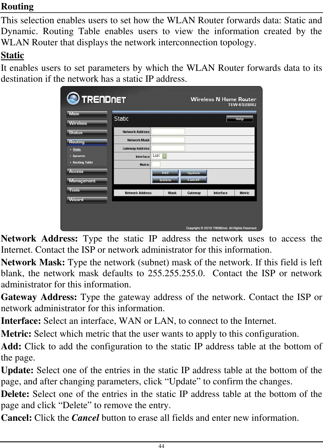
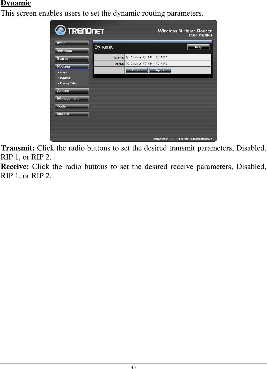
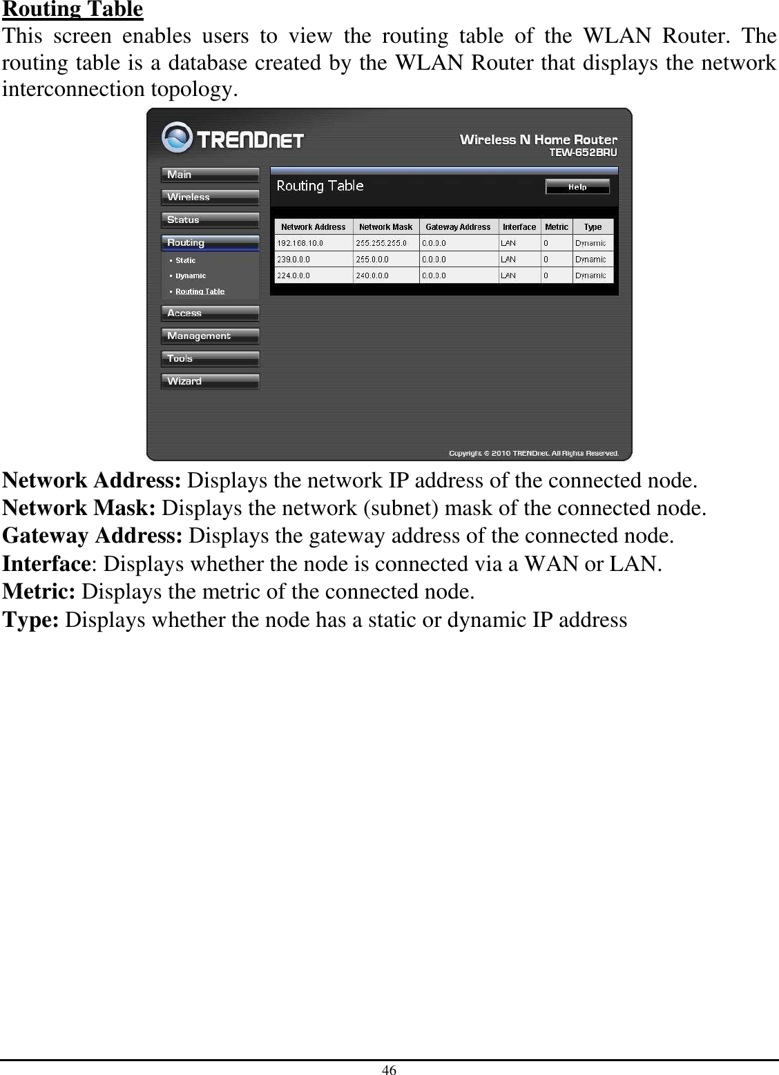
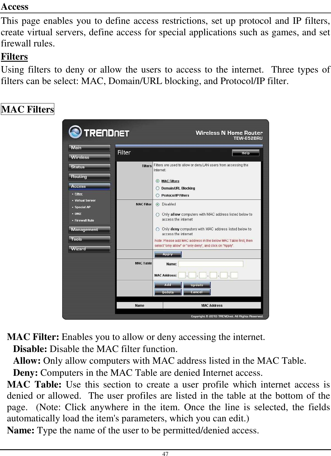
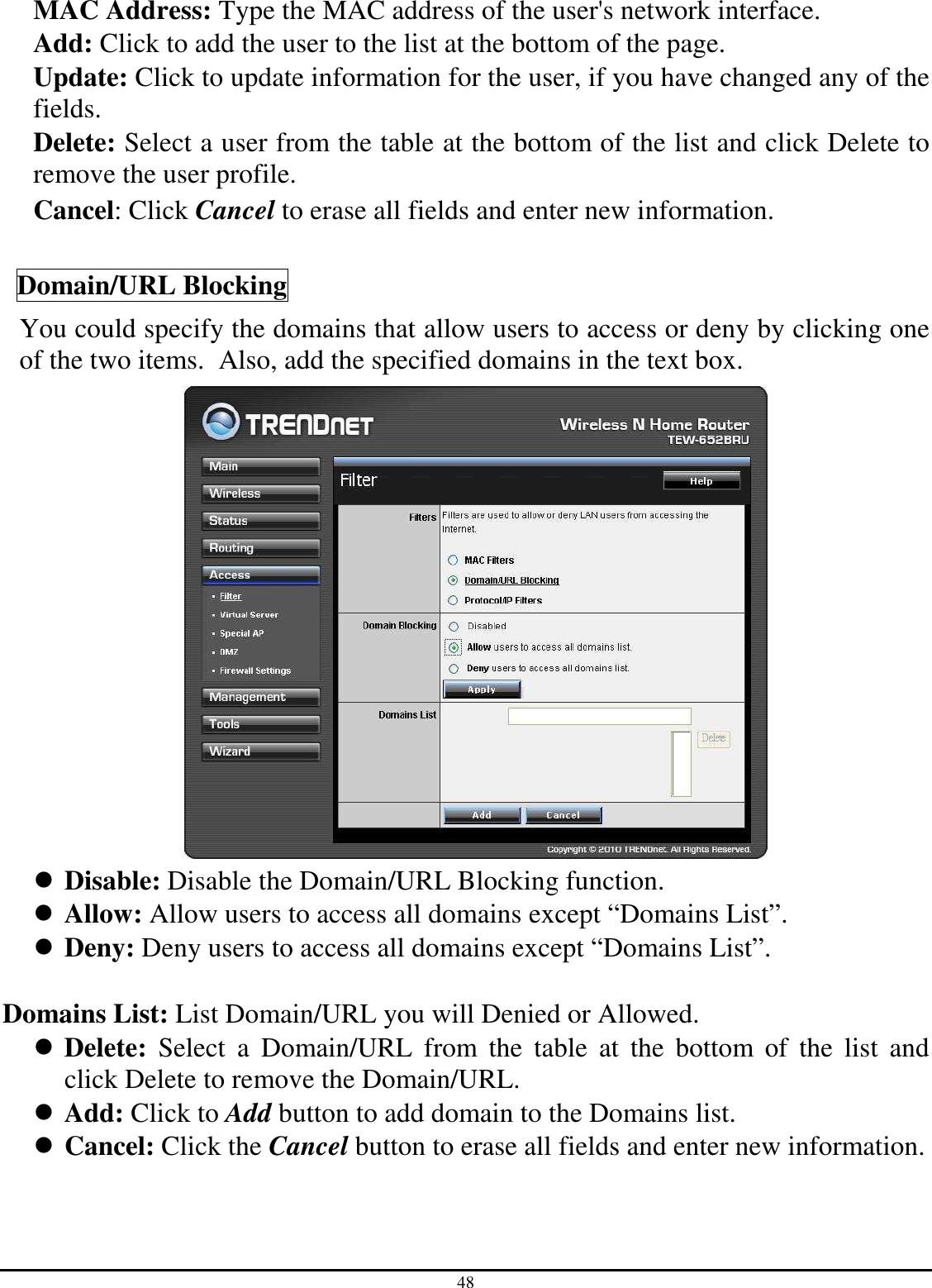
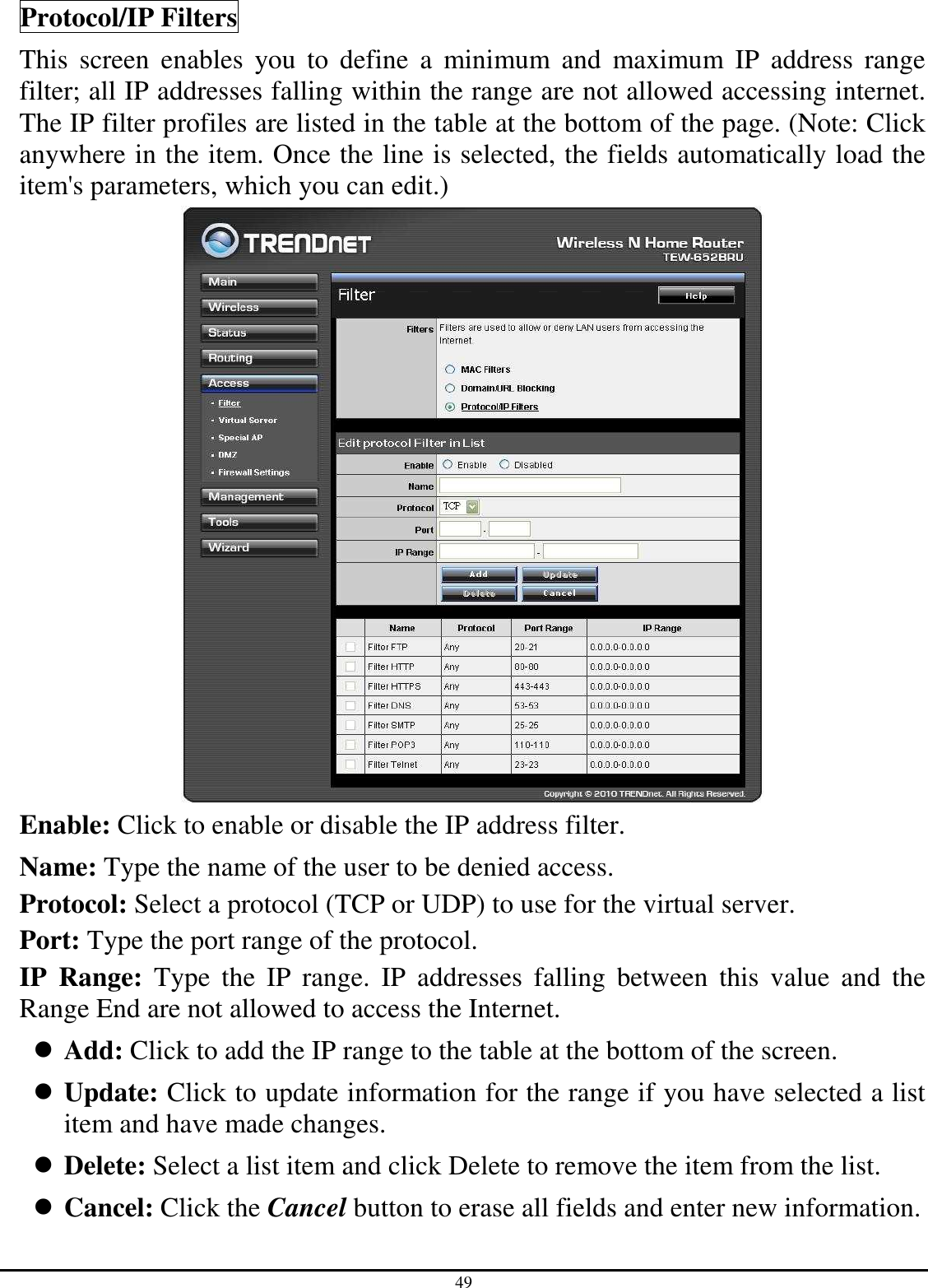
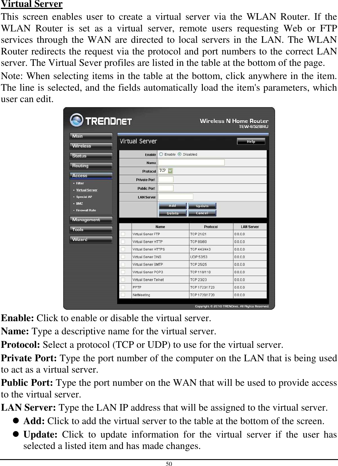
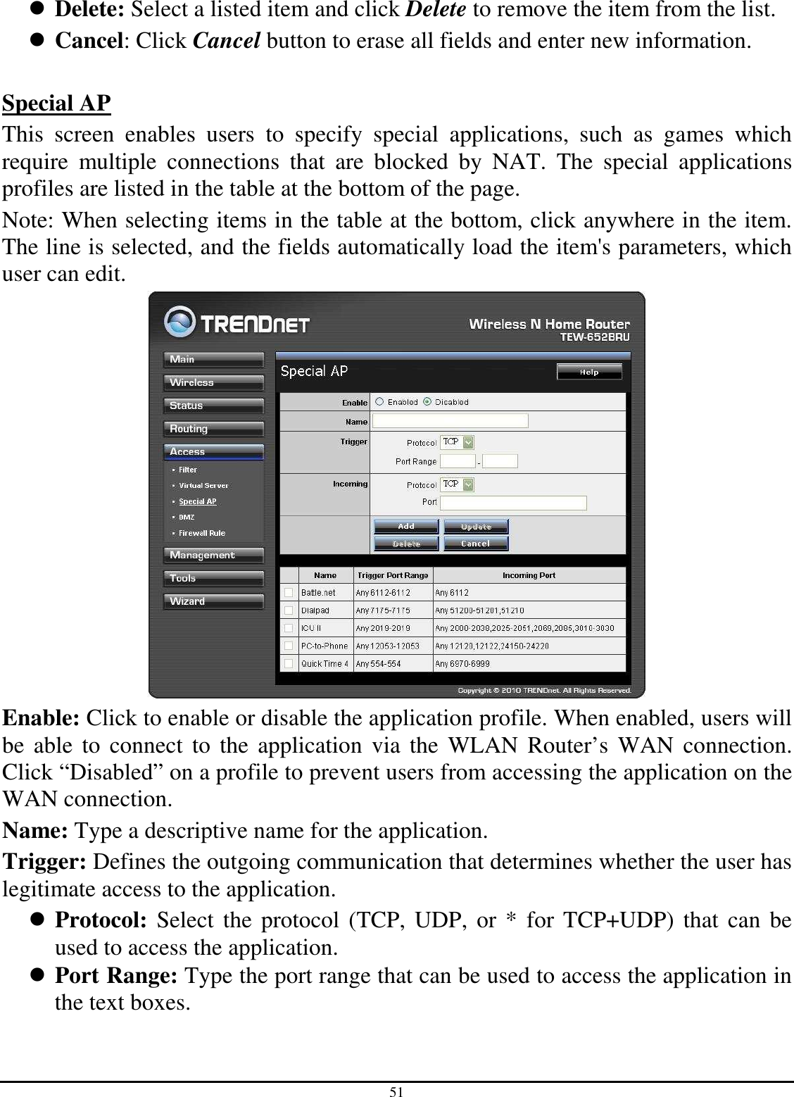
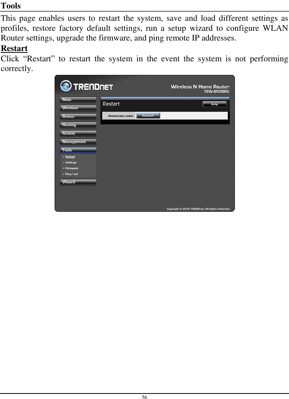
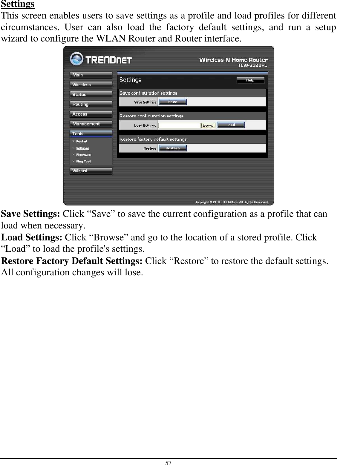
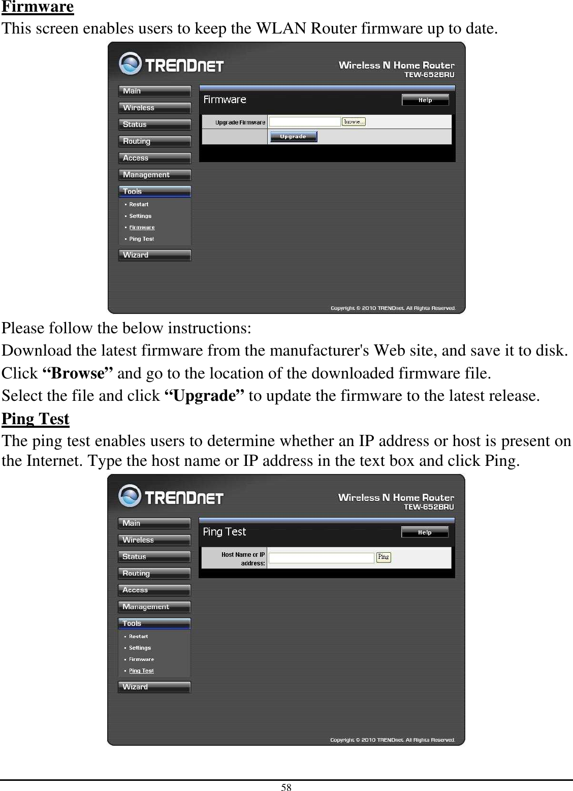
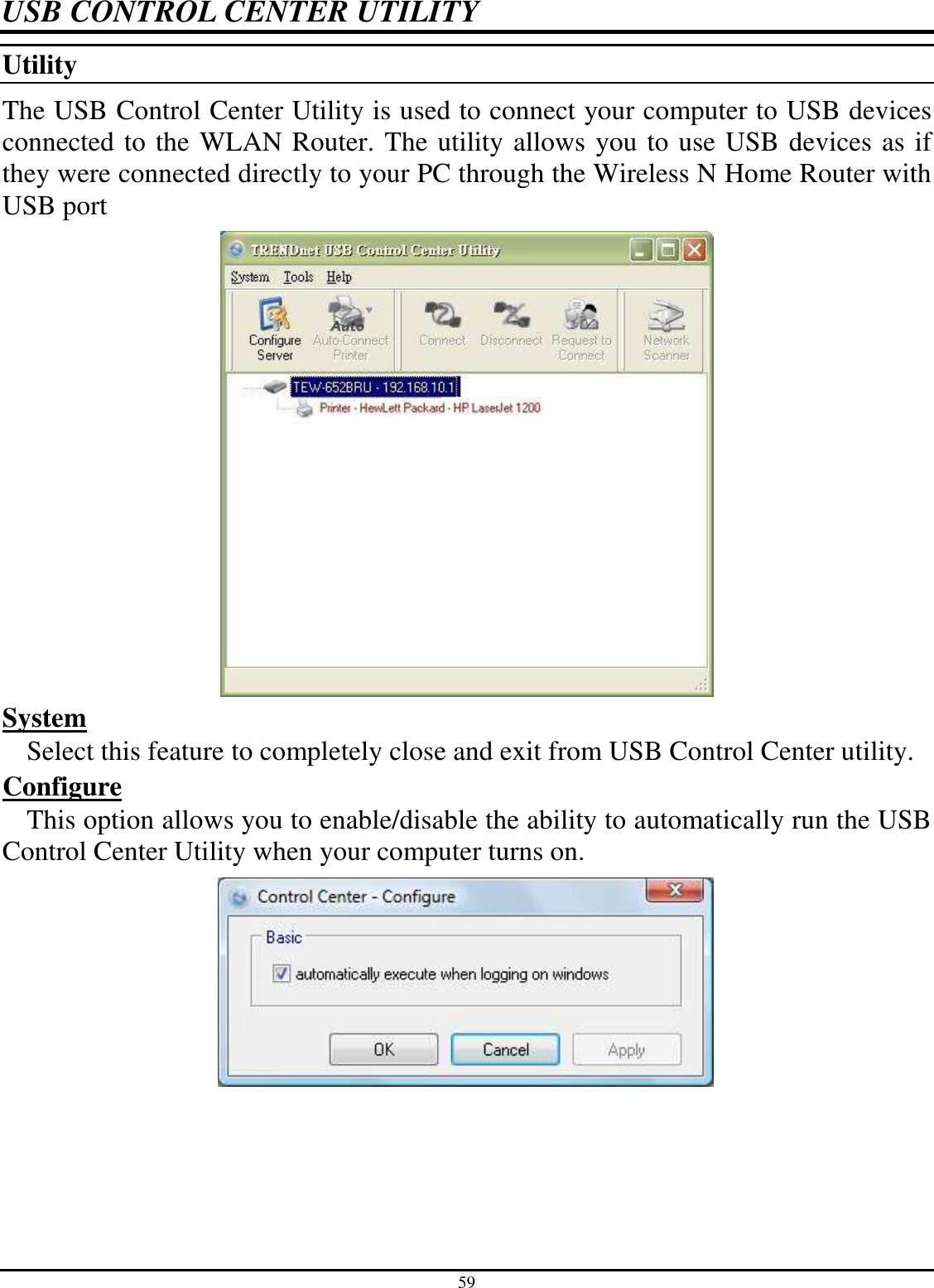
Manual Part 2
Manual Part 2
Navigation menu
Upload a User Manual
Namespaces
Wiki Guide
HTML
PDF
Info
Views
User Manual
Discussion / Help
Navigation