Cameron Health CHI1010 SQ-RX Model 1010 User Manual 102098 004 rev a qxp
Cameron Health, Inc. SQ-RX Model 1010 102098 004 rev a qxp
User Manual
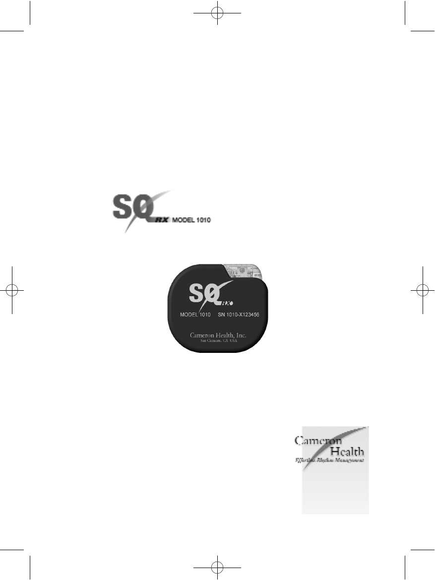
SQ-RX™PULSE GENERATOR
A COMPONENT OF THE S-ICD®SYSTEM
USER’S MANUAL
MODEL 1010
102098 004 rev a.qxp 12/2/2008 7:43 AM Page 1

Copyright©2008 Cameron Health, Inc., San Clemente, CA USA
All rights reserved.
Limited Software License and Equipment Use.
S-ICD®is a registered trademark of Cameron Health, Inc. SQ-RX™, Q-TRAK™, Q-GUIDE™
and Q-TECH™ are all trademarks of Cameron Health, Inc. Manuals or other written
documentation may not be copied or distributed without Cameron Health, Inc. authorization.
Cameron Health, Inc.
905 Calle Amanecer
Suite 300
San Clemente, CA 92673
USA
Tel: 1 949 498 5630
Free: 1 877 SICD 411
1 877 742 3411
Fax: 1 949 498 5932
URL: www.cameronhealth.com
Cameron Health BV
World Trade Center
Nieuwe Stationsstraat 10
6811 KS Arnhem
The Netherlands
Tel: 31 26 3550260
Free: 800 SICD 4 YOU
800 7423 4 968
Fax: 31 26 3550269
URL: www.cameronhealth.com
102098 004 rev a.qxp 12/2/2008 7:43 AM Page 2

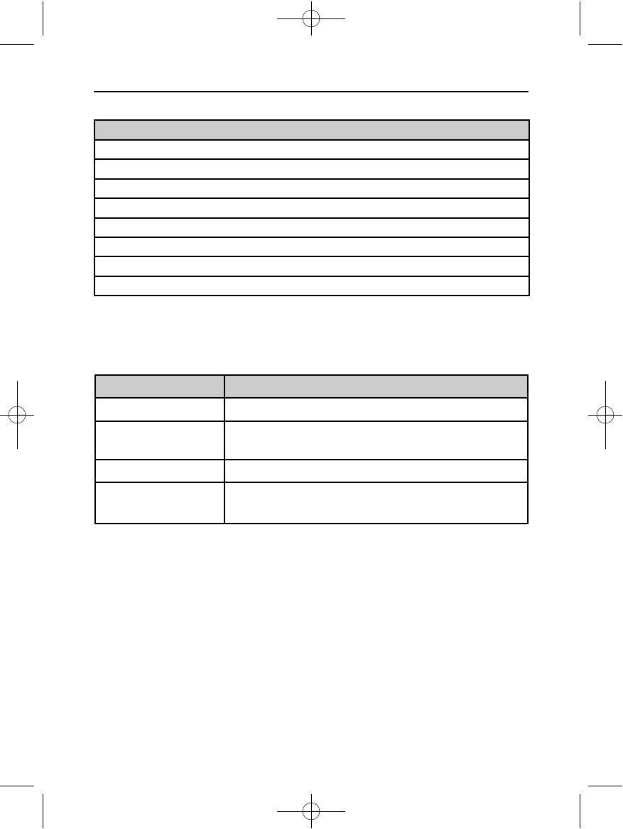
Table of Contents
General Description 5
Description 5
Indications for Use 5
Contraindications 5
Warnings and Cautions 5
General 5
SQ-RX Pulse Generator Packaging 6
Storage and Handling 6
Implant and Programming 6
Explanting the System 7
Use of Other Medical Therapies/Diagnostic Procedures 7
Electromagnetic Interference (EMI) Outside of the Hospital Environment 8
Potential Adverse Events 8
Clinical Studies 10
Results 11
Observed Adverse Events 13
Patient Screening 14
Operation 17
General 17
Modes of Operation 17
Shelf Mode 17
Therapy On Mode 17
Therapy Off Mode 17
Sensing Configuration and Gain Selection 18
Sensing and Tachyarrhythmia Detection 18
Detection Phase 18
Certification Phase 18
Decision Phase 19
Therapy Zones 19
Analysis in the Therapy Zones 19
Charge Confirmation 20
Therapy Delivery 21
Smart Charge 21
Redetection 21
Shock Waveform and Polarity 21
Post-Shock Bradycardia Pacing Therapy 22
Manual and Rescue Shock Delivery 22
Additional Features of the S-ICD System 22
102098 004 rev a.qxp 12/2/2008 7:43 AM Page 3
Magnet Application 22
Auto Capacitor Reformation 22
Internal Waning System (Beeper Control) 23
Arrhythmia Induction 23
System Diagnostics 23
Storing and Analyzing Data 24
Patient Data 25
S-ICD System Magnet Model 4520 26
Using the SQ-RX Pulse Generator 27
Implanting the S-ICD System 27
Creating the Device Pocket 27
Implanting the Q-TRAK Subcutaneous Electrode 28
Connecting the Electrode to the Device 31
Setting Up the SQ-RX Pulse Generator 33
Post Implant Follow-Up Procedures 34
Explanting the S-ICD System 34
Federal Communications Commission (FCC) Compliance 35
Additional Information 36
Specifications 36
Definitions of Package Label Symbols 41
Appendix 42
S-ICD System and Pacemaker Interaction 42
Limited Warranty 43
Table of Contents (Continued)
102098 004 rev a.qxp 12/2/2008 7:43 AM Page 4

Description
The SQ-RX Pulse Generator (the “device”) is a component of the Cameron Health S-ICD
System, which is prescribed for patients when cardiac arrhythmia management is warranted.
Implanted with the Q-TRAK Subcutaneous Electrode (the “electrode”), the device detects
cardiac activity and provides defibrillation therapy.
Indications for Use
The S-ICD System is intended to provide defibrillation therapy for the treatment of life-
threatening ventricular tachyarrhythmias.
Contraindications
The S-ICD System is contraindicated for patients with symptomatic bradycardia, incessant
ventricular tachycardia and patients with documented spontaneous, frequently recurring
ventricular tachycardia that is reliably terminated with anti-tachycardia pacing.
Unipolar pacemakers are contraindicated for use with the S-ICD System.
Warnings and Cautions
Before using the S-ICD System, read and follow all warnings and cautions provided in this
manual.
The S-ICD System contains sterile products for single use only. Do not resterilize.
Handle the S-ICD System with care at all times and maintain proper sterile technique.
All Cameron Health implantable components are designed for use with the Cameron Health
S-ICD System only. Connection of any S-ICD System components to any other ICD system will
result in failure to deliver life saving defibrillation therapy.
General
• External defibrillation equipment should be available for immediate use during the
implantation procedure and follow-up.
• Placing a magnet over the SQ-RX Pulse Generator suspends arrhythmia detection
and therapy response. Removing the magnet resumes arrhythmia detection and
therapy response. Refer to the S-ICD System Magnet Model 4520 section.
• Battery depletion will eventually cause the SQ-RX Pulse Generator to stop
functioning. Defibrillation and excessive numbers of charging cycles shorten the
battery longevity.
5
SQ-RX PULSE GENERATOR GENERAL DESCRIPTION
102098 004 rev a.qxp 12/2/2008 7:43 AM Page 5

SQ-RX Pulse Generator Packaging
The device has been sterilized with ethylene oxide gas and is packaged in a sterile container
that is suitable for use in the operating field. Store in a clean, dry area. Each package
contains the following:
• One SQ-RX Pulse Generator Model 1010
• One Bi-Directional Torque Wrench
• SQ-RX Pulse Generator Model 1010 User’s Manual
Before opening any package, visually inspect the sterile packaging to ensure the contents are
not contaminated or been previously used. Do not use if any of the following conditions exist:
• Tears or punctures in the packaging
• “Use By” date has expired
• Evidence of damage exists
• Sterile package is dropped from a height of 24 in/61 cm or greater
Return the product to Cameron Health if any of these conditions exist. Contact your local
Cameron Health representative or Customer Service Department for instructions and return
packaging.
Storage and Handling
• Store the S-ICD System components in a clean, dry area away from magnets or any
other electromagnetic interference source that could cause damage to the device.
• Do not expose the S-ICD System to temperatures outside the recommended storage
temperatures indicated on the device package.
• Do not modify, cut, kink, crush, stretch or otherwise damage any component of the S-
ICD System. Impairment to the S-ICD System may result in an inappropriate shock
or failure to deliver therapy to the patient.
Implant and Programming
• Use only the electrode insertion tool to tunnel.
• Suture only those areas indicated in the implant procedure.
• Do not place a suture directly on the electrode body.
• Use appropriate anchoring techniques as described in the implant procedure to
prevent S-ICD System dislodgement and/or migration. Dislodgement and/or
migration of the S-ICD System may result in an inappropriate shock or failure to
deliver therapy to the patient.
• Use only the Q-TECH Programmer (the “programmer”) and appropriate software for
communicating with and programming the device.
6
SQ-RX PULSE GENERATOR GENERAL DESCRIPTION
102098 004 rev a.qxp 12/2/2008 7:43 AM Page 6

7
SQ-RX PULSE GENERATOR GENERAL DESCRIPTION
• Verify the device is in Shelf mode or Therapy Off to prevent the delivery of unwanted
shocks to the patient or the person handling the device during the implant
procedure.
Explanting the System
• To avoid inadvertent shock discharges, program the device to Therapy Off during
device explantation or postmortem procedures.
• Remove the device from a deceased patient prior to cremation. The device battery
may explode when exposed to extreme temperatures.
Use of Other Medical Therapies/Diagnostic Procedures
• External defibrillation or cardioversion may damage the implanted SQ-RX Pulse
Generator. Current flow through the SQ-RX Pulse Generator may be minimized by
avoiding the placement of defibrillation paddles directly over the device.
• Do not expose a patient with an implanted S-ICD System to diathermy. The
interaction of diathermy therapy with an implanted SQ-RX Pulse Generator can
damage the SQ-RX Pulse Generator and cause patient injury.
• Do not expose the patient to MRI scanning. MRI scanning can damage the SQ-RX
Pulse Generator and cause patient injury.
• Electrical interference or “noise” from sources such as electrosurgical and
monitoring equipment can interfere with the communication between the
programmer and the SQ-RX Pulse Generator or cause inappropriate therapy. If
interference occurs, move the programmer away from the source of the interference.
• Ionizing radiation therapy, such as radioactive cobalt, linear accelerators, and
betatrons, may adversely affect the S-ICD System operation. Therapeutic ionizing
radiation may not be immediately detected; however, it can damage the electronic
components of the SQ-RX Pulse Generator. Follow these conditions to minimize the
risks of ionizing radiation:
§Shield the SQ-RX Pulse Generator with a radiation-resistant material,
regardless of the distance between the SQ-RX Pulse Generator and the
radiation beam.
§Do not project the radiation port directly at the SQ-RX Pulse Generator.
§Always evaluate the S-ICD System operation following each radiation
treatment.
• Lithotripsy and other therapeutic forms of ultrasound may damage the SQ-RX Pulse
Generator. If required, avoid direct flow of the pulse waves near the site of the
implanted device.
• Use caution during ablation procedures. Program the S-ICD System to Therapy Off.
Keep the current path (electrode tip to ground) as far away as possible from the
implanted SQ-RX Pulse Generator and electrode.
102098 004 rev a.qxp 12/2/2008 7:43 AM Page 7
8
SQ-RX PULSE GENERATOR GENERAL DESCRIPTION
Electromagnetic Interference (EMI) Outside of the Hospital Environment
Exposure to Electromagnetic Interference (EMI) or Static Magnetic Field sources may
suspend tachyarrhythmia detection and cause temporary inhibition of therapy delivery. EMI
may also trigger delivery of a shock in the absence of a tachyarrhythmia. Automatic sensing
and detection of tachyarrhythmias will resume when the patient moves away from the EMI or
static magnetic field source.
To minimize the risk, advise patients to avoid sources of EMI or static magnetic fields having
strengths >10 gauss or 1 mTesla.
• Sources of EMI include, but are not limited to:
• High-voltage power lines
• Arc welding equipment
• Electrical smelting furnaces
• Large radio-frequency transmitters (such as radar)
• Alternators on running engines in automobiles
• Communications equipment (such as high-power radio transmitters)
• Sources of strong static magnetic fields may include the following:
• Industrial transformers and motors
• Large stereo speakers
• Magnetic wands, such as those used for airport security
Patients should seek medical guidance from their physician before entering an area where a
posted sign prohibits patients with an implantable cardioverter defibrillator or pacemaker.
Potential Adverse Events
Potential adverse events related to implantation of the S-ICD System may include, but are
not limited to, the following:
• Acceleration of arrhythmia
• Allergic reaction
• Bleeding
• Conductor fracture
• Cyst formation
• Death
• Electrode dislodgement
• Electrode insulation failure
• Electrode deformation and/or breakage
• Erosion/extrusion
• Improper electrode connection to the device
• Inappropriate shock delivery
102098 004 rev a.qxp 12/2/2008 7:43 AM Page 8

• Infection
• Hematoma
• Hemothorax
• Keloid formation
• Migration or dislodgement
• Muscle stimulation
• Nerve damage
• Pneumothorax
• Postoperative discomfort
• Potential mortality due to inability to defibrillate or pace
• Premature battery depletion
• Random component failures
• Tissue necrosis
• Ventricular arrhythmia
If any adverse events occur, invasive corrective action and/or S-ICD System modification or
removal may be required.
Patients who receive an S-ICD System may develop psychological disorders that include, but
are not limited to, the following:
• Depression
• Fear of shocks
• Phantom shocks
9
SQ-RX PULSE GENERATOR GENERAL DESCRIPTION
102098 004 rev a.qxp 12/2/2008 7:43 AM Page 9

Clinical Studies
10
SQ-RX PULSE GENERATOR GENERAL DESCRIPTION
102098 004 rev a.qxp 12/2/2008 7:43 AM Page 10

Results
11
SQ-RX PULSE GENERATOR GENERAL DESCRIPTION
102098 004 rev a.qxp 12/2/2008 7:43 AM Page 11

Results
12
SQ-RX PULSE GENERATOR GENERAL DESCRIPTION
102098 004 rev a.qxp 12/2/2008 7:43 AM Page 12

Observed Adverse Events
13
SQ-RX PULSE GENERATOR GENERAL DESCRIPTION
102098 004 rev a.qxp 12/2/2008 7:43 AM Page 13
14
SQ-RX PULSE GENERATOR
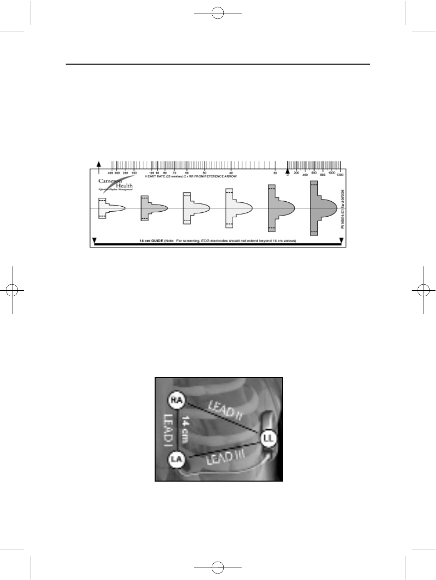
Instructions for using the screening tool:
1. Place standard ECG skin electrodes according to Figure 2. This will simulate the three
sensing vectors used by the device.
• Electrode LL should be placed in a lateral location, at the 5th intercostal space along
the mid-axillary line.
• Electrode LA should be placed 1 cm to the left of the patient’s xiphoid.
• Electrode RA should be placed 14 cm superior to the LA electrode, 1 cm left lateral of
the sternal margin.
SQ-RX PULSE GENERATOR GENERAL DESCRIPTION
Figure 1: Patient Screening Tool
Figure 2: Placement of ECG Leads
Patient Screening
The patient screening tool (Figure 1) is a customized measurement tool made of transparent
plastic printed with colored profiles. The profiles are designed to ensure appropriate device
performance by identifying signal characteristics that may lead to unsatisfactory detection
outcomes for a patient before implant.
The patient screening tool can be obtained from any Cameron Health representative or by
calling the Customer Service Department.
102098 004 rev a.qxp 12/2/2008 7:43 AM Page 14

15
SQ-RX PULSE GENERATOR
2. Record 10 - 20 seconds of ECG using a sweep speed of 25 mm/sec and ECG gain between
5 - 20 mm/mV (use the largest ECG gain that does not result in clipping).
3. Record ECG signals in at least two postures: (1) Supine and (2) Standing.
4. Select a representative QRS complex from the first sense vector.
Note: If multiple morphologies are noted (e.g., bigeminy, pacing, etc.), all morphologies
should be tested as described below before the vector is deemed acceptable.
5. Select the colored profile from the Patient Screening Tool that best matches the
amplitude of the QRS from Step 4. The QRS peak must fall within the window bounded
by the dotted line and the peak of the colored profile (Figure 3). For biphasic signals, the
larger peak should be used to determine the appropriate colored profile.
Note: ECG gains > 20 mm/mV are not permitted. If when printed at the maximum 20
mm/mV gain the QRS peak does not reach the minimum boundary (dotted line) of the
smallest colored profile, the vector should be deemed unacceptable.
6. Align the left edge of the selected colored profile with the onset of the QRS complex and
the horizontal line with the complex’s isoelectric baseline.
7. If the entire QRS complex and trailing T-wave are contained within the colored profile,
the vector/posture combination is deemed acceptable. If any portion of the QRS complex
or trailing T-wave extends above or below the colored profile, the sense vector is deemed
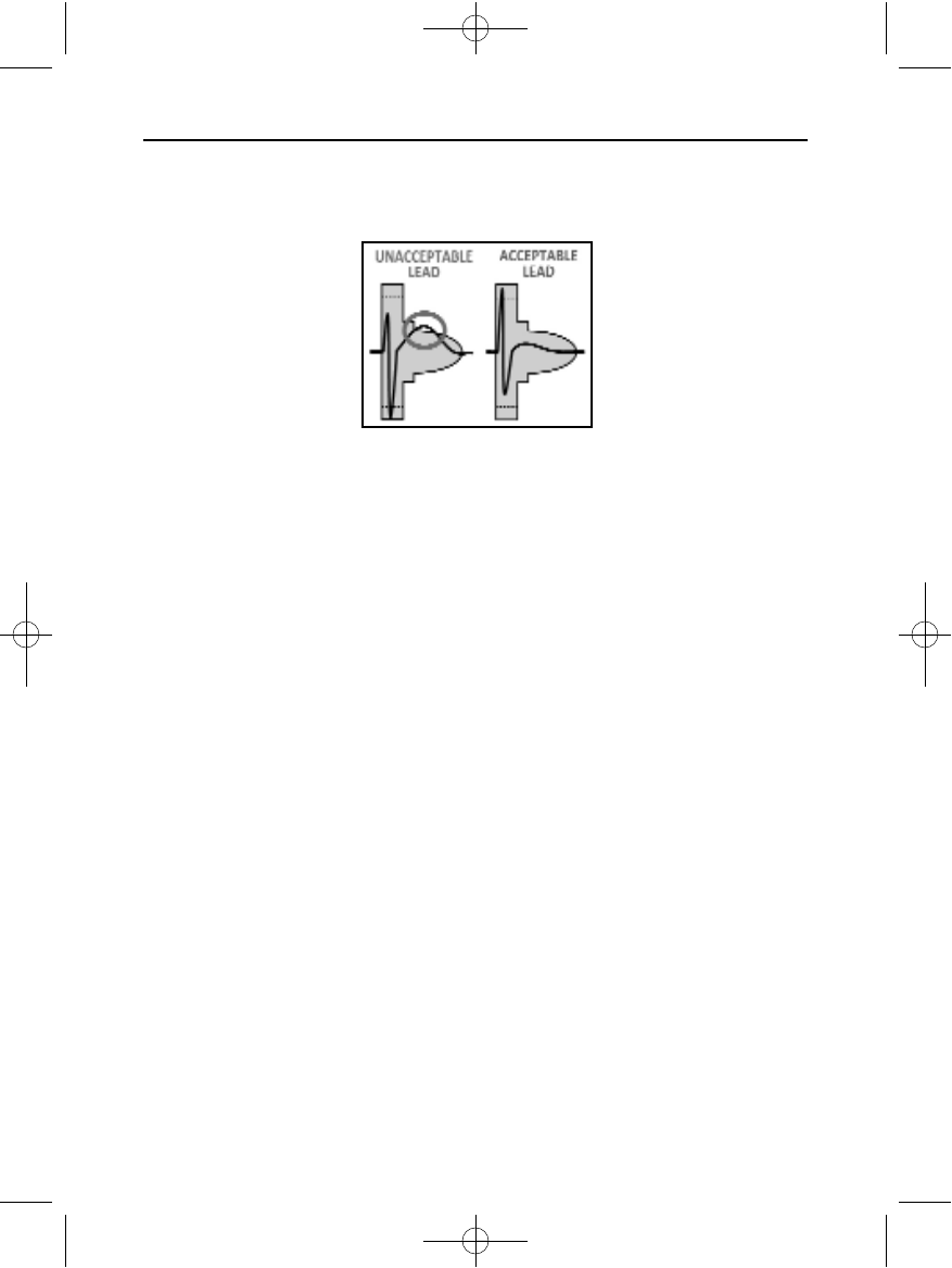
unacceptable (Figure 4).
SQ-RX PULSE GENERATOR GENERAL DESCRIPTION
Figure 3: Determine colored profile for QRS amplitude
Figure 4: QRS profile selection
102098 004 rev a.qxp 12/2/2008 7:43 AM Page 15
8. Test all vectors in each posture.
9. A patient should be considered suitable for implant if at least one sense vector is
deemed acceptable for all tested postures (Figure 5).
16
SQ-RX PULSE GENERATORSQ-RX PULSE GENERATOR GENERAL DESCRIPTION
Figure 5: Acceptance of one sense vector
102098 004 rev a.qxp 12/2/2008 7:43 AM Page 16

General
The S-ICD System is designed for ease of use and simplicity of patient management. The
arrhythmia detection system employs up to two rate zones, and the device has a single
automatic response to a detected ventricular tachyarrhythmia – a nonprogrammable,
maximum-energy, biphasic shock of 80 J. The device has a number of automatic functions
designed to reduce the amount of time required for implantation, initial programming and
patient follow-up.
Modes of Operation
The device has three modes of operation:
• Shelf
• Therapy On
• Therapy Off
Shelf Mode
The Shelf mode is a low power consumption state intended for storage only. When
communication is initiated between the device and the programmer, a full-energy capacitor
reformation is performed and the device is prepared for set-up. Once the device is taken out
of Shelf mode, it cannot be reprogrammed back into Shelf mode.
Therapy On Mode
The Therapy On mode is the primary operating mode of the device, allowing automatic
detection of and response to ventricular tachyarrhythmias. All device features are active.
Note: The device must be programmed out of Shelf mode before being programmed to
Therapy On.
.
Therapy Off Mode
The Therapy Off mode disables automatic therapy delivery and enables manual control of
shock delivery. Programmable parameters may be viewed and adjusted via the programmer.
Also, the subcutaneous electrogram (S-ECG) may be displayed or printed.
The device automatically defaults to Therapy Off when taken out of Shelf mode.
Note: Manual and rescue shock therapy are available only after the initial Setup
process is complete. Refer to the Q-TECH Programmer User’s Manual for details.
.
17
SQ-RX PULSE GENERATORSQ-RX PULSE GENERATOR OPERATION
102098 004 rev a.qxp 12/2/2008 7:43 AM Page 17

Sensing Configuration and Gain Selection
During the Automatic Setup process, the device automatically selects an optimal sensing
vector based on an analysis of cardiac signal amplitude and signal-to-noise ratio. This
analysis is performed on the three available vectors:
• Primary: Sensing from the proximal electrode ring on the
electrode to the active surface of the device.
• Secondary: Sensing from the distal sensing electrode ring on the
electrode to the active surface of the device.
• Alternate: Sensing from the distal sensing electrode ring to the proximal
sensing electrode ring on the electrode.
The sensing vector can also be selected manually. The Q-TECH Programmer User’s Manual
provides instructions for sensing vector selection.
The device automatically selects an appropriate gain setting during the Automatic Setup
process. The gain can also be manually selected, as further explained in the Q-TECH
Programmer User’s Manual. There are two gain settings:
• 1x Gain (±4 mV): Selected when the signal amplitude is clipped at the 2x gain
setting.
• 2x Gain (±2 mV): Selected when the signal amplitude is not clipped at this setting.
Sensing and Tachyarrhythmia Detection
The device is designed to prevent inappropriate therapy delivery as a result of noise sensing
or multiple counting of individual cardiac cycles. This is accomplished by an automatic
analysis of sensed signals, which includes event detection, certification and decision phases.
Detection Phase
During the Detection Phase, the device uses a detection threshold to identify sensed events.
The detection threshold is automatically adjusted continuously using amplitudes of recently
detected electrical events. In addition, detection parameters are modified to increase
sensitivity when rapid rates are detected. Events detected during the Detection Phase are
passed on to the Certification Phase.
Certification Phase
The Certification Phase examines the detections and classifies them as certified cardiac
events or as suspect events. Certified events are used to ensure that an accurate heart rate is
passed to the Decision Phase. A suspect event can be one whose pattern and/or timing
indicates the signal is caused by noise, such as a muscle artifact or some other extraneous
signal. Events are also marked as suspect if they appear to derive from double or triple
detections of single cardiac events. The device is designed to identify and correct multiple
detections of wide QRS complexes and/or erroneous detections of a T-wave.
18
SQ-RX PULSE GENERATORSQ-RX PULSE GENERATOR OPERATION
102098 004 rev a.qxp 12/2/2008 7:43 AM Page 18
19
SQ-RX PULSE GENERATOR
Decision Phase
The Decision Phase examines all certified events and continuously calculates a running four
R-to-R interval average (4 RR average). The 4 RR average is used throughout the analysis as
an indicator of the heart rate.
Therapy Zones
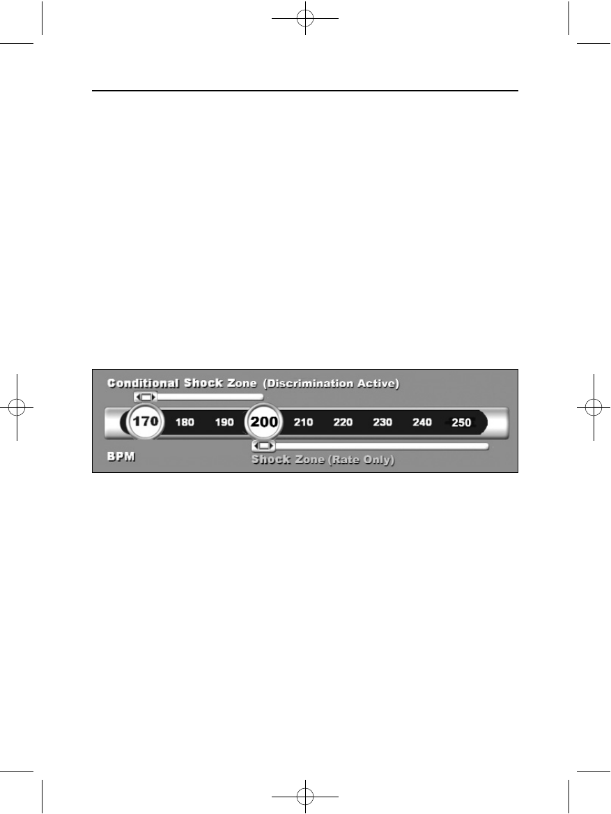
The device allows the selection of rate thresholds that define a Shock Zone and an optional
Conditional Shock Zone. In the Shock Zone, rate is the only criterion used to determine if a
rhythm will be treated with a shock. The Conditional Shock Zone has additional
discriminators used to determine if a shock is warranted to treat an arrhythmia.
The Shock Zone is programmable from 170 - 250 bpm in increments of 10 bpm. The
Conditional Shock Zone must be lower than the Shock Zone, with a range of 170 - 240 bpm in
increments of 10 bpm.
Graphically, the use of a Shock Zone and Conditional Shock Zone is shown in Figure 6.
The device declares a Tachycardia when the 4RR average enters either therapy zone.
Once a Tachycardia is declared, the 4RR average must become longer (in ms) than the
lowest rate zone, plus 40 ms for 24 cycles for the device to consider the episode to have
ended. In the Shock Zone, treatable arrhythmias are determined by rate alone.
Analysis in the Conditional Shock Zone
In contrast, rate and morphology are analyzed in the Conditional Shock Zone. The
Conditional Shock Zone is designed to discriminate between treatable and other high-rate
events such as atrial fibrillation, sinus tachycardia and other supraventricular tachycardias.
SQ-RX PULSE GENERATOR OPERATION
Figure 6: Shock Zone Rate Detection Diagram
102098 004 rev a.qxp 12/2/2008 7:43 AM Page 19
20
SQ-RX PULSE GENERATORSQ-RX PULSE GENERATOR OPERATION
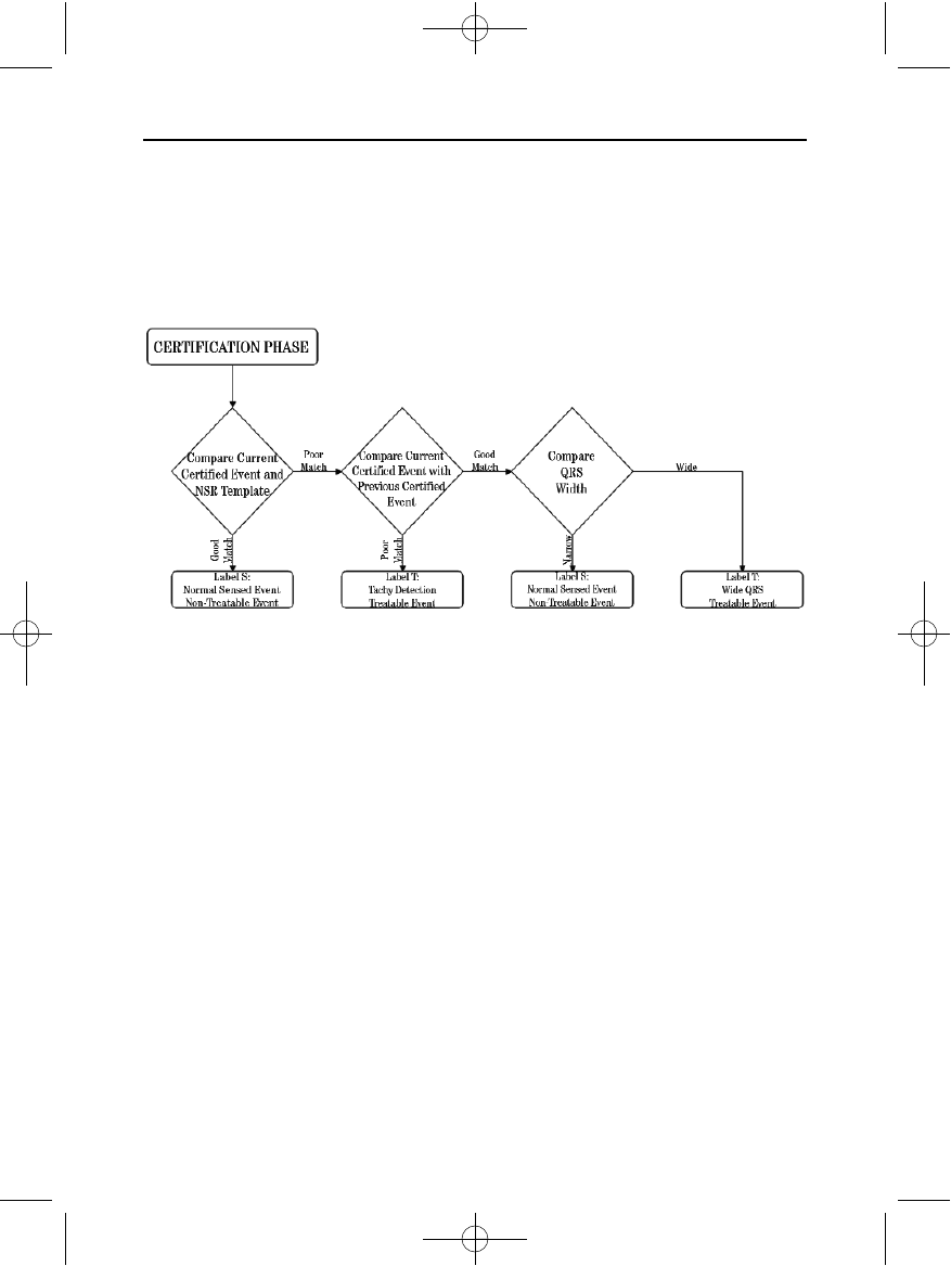
A normal sinus rhythm template (NSR Template) is formed during device initialization. This
NSR template is used during analysis in the Conditional Shock Zone to identify treatable
arrhythmias. In addition to morphology comparison with the NSR template, other
morphologic analysis is used to identify polymorphic rhythms. Morphology and QRS width are
used to identify monomorphic arrhythmias such as ventricular tachycardia. If the Conditional
Shock Zone is enabled, then an arrhythmia is found to be treatable according to the decision
tree shown in Figure 7.
For some patients, a NSR Template may not be formed during device initialization as a result
of variability in their cardiac signal at resting heart rates. For such patients, the device uses
beat-to-beat morphology and QRS width analysis for arrhythmia discrimination.
Charge Confirmation
The device must charge the internal capacitors before shock delivery. Confirmation of the
ongoing presence of a tachyarrhythmia requires monitoring a moving widow of the 24 most
recent intervals defined by certified events. Charge confirmation employs an X (treatable
interval) out of Y (total intervals in the window) strategy to accomplish this. If 18 of the 24
most recent intervals are found to be treatable, the device begins to analyze rhythm
persistence. Persistence analysis requires the X out of Y condition be maintained or
exceeded for at least two consecutive intervals; however, this value may be increased as a
result of Smart Charge, as explained below.
Capacitor charging is initiated when the following three conditions are met:
1. X of Y criterion met
2. Persistence requirement is met
3. The last two certified intervals are in the treatable zone.
Figure 7: Decision tree for determining treatable arrhythmias in the Conditional Shock Zone
102098 004 rev a.qxp 12/2/2008 7:43 AM Page 20

21
SQ-RX PULSE GENERATORSQ-RX PULSE GENERATOR OPERATION
Therapy Delivery
Rhythm analysis continues throughout the capacitor charging process. Capacitor charging is
aborted if the 4 RR average interval becomes longer (in ms) than the lowest rate zone, plus
40 ms for 24 intervals. When this occurs, an untreated episode is declared and a Smart
Charge extension is incremented, as explained below.
Capacitor charging continues until the capacitor has reached its target voltage, at which
time reconfirmation is performed. Reconfirmation requires the last three consecutive
detected intervals (regardless of whether the intervals are certified or suspect) to be faster
than the lowest therapy zone.
Reconfirmation is always performed and shock delivery is non-committed until
reconfirmation is complete. Once the criteria for reconfirmation is met, the shock is
delivered.
Smart Charge
Smart Charge is a feature that automatically increases the Persistence requirement by three
intervals each time an untreated episode is declared, up to a maximum of five extensions.
Thus, after an untreated episode, the requirement to start capacitor charging becomes more
stringent. The Smart Charge extension value can be reset to its nominal value (zero
extensions) using the programmer. The Smart Charge feature cannot be disabled, though it
is not used for the second and later shocks that occur during any given episode.
Redetection
A blanking period is enabled following delivery of a high-voltage shock. After delivery of the
first shock, up to four additional shocks will be delivered if the episode does not terminate.
Rhythm analysis for delivering shocks 2 - 5 generally follows the detection steps described
above, with the following exceptions:
1. Following the first shock delivery, the X/Y criterion is modified to require 14 treatable
intervals in the last 24 (14/24), rather than 18.
2. The Persistence Factor is always set to two intervals (i.e., not modified by the Smart
Charge feature).
Shock Waveform and Polarity
The shock waveform is biphasic, with a fixed tilt of 50%. The shock is delivered synchronously
unless a 1000 ms time out expires without an event being detected for synchronization, at
which time the shock is delivered in an asynchronous manner.
The device is designed to automatically select the appropriate polarity for therapy. Both
102098 004 rev a.qxp 12/2/2008 7:43 AM Page 21

standard and reversed polarity shocks are available. If a shock fails to convert the arrhythmia
and subsequent shocks are required, polarity is automatically reversed for each successive
shock. The polarity of the successful shock is then retained as the starting polarity for future
episodes. Polarity can also be selected during the Induction and Manual Shock process to
facilitate device-based testing.
Post-Shock Bradycardia Pacing Therapy
The device provides optional post-shock, on-demand bradycardia pacing therapy. When
enabled via the programmer, bradycardia pacing occurs at a non-programmable rate of 50
bpm for up to 30 seconds. The pacing output is fixed at 200 mA, and uses a 15-ms biphasic
waveform.
Pacing is inhibited if the intrinsic rate is greater than 50 bpm. In addition, post-shock pacing
is terminated if a tachyarrhythmia is detected or a magnet is placed over the device during
the post-shock pacing period.
Manual and Rescue Shock Delivery
Upon programmer command, the device can deliver manual and rescue shocks. Manual
shocks are programmable from 10 to 80 J delivered energy in 5 J steps. Rescue shocks are
non-programmable, delivering the maximum output of 80 J.
Note: The Rescue Shock will NOT be inhibited with magnet application.
Additional Features of the S-ICD System
This section presents descriptions of several additional features available in the S-ICD
System.
Magnet Application
Application of the S-ICD System Magnet over the device will:
• Suspend arrhythmia detection
• Inhibit shock therapy delivery except for a programmer-commanded Rescue Shock
• Terminate post-shock pacing therapy
• Prohibit arrhythmia induction testing
• Activate the device’s beeper with each detected QRS complex for 60 seconds
Note: Magnet application does not affect wireless communication between the device
and the programmer.
Auto Capacitor Reformation
The device automatically performs a full-energy (80 J) capacitor reformation when taken out
of Shelf mode and every four months until the device reaches End of Life (EOL). The energy
22
SQ-RX PULSE GENERATORSQ-RX PULSE GENERATOR OPERATION
102098 004 rev a.qxp 12/2/2008 7:43 AM Page 22

23
SQ-RX PULSE GENERATOR
output and reformation time interval are non-programmable.
The Auto Capacitor Reformation interval is reset after any 80 J capacitor charge is delivered
or aborted.
Internal Warning System – Beeper Control
The device has an internal warning system (beeper) that emits an audible tone to alert the
patient to certain device conditions that require prompt consultation with the physician.
These conditions include:
• Elective Replacement Indicator (ERI)
• Electrode impedance out of range
• Prolonged charge times
• Failed Device Integrity Check
This internal warning system is automatically activated at time of implant. Once triggered,
the beeper sounds for 16 seconds every nine hours until the trigger condition has been
resolved. If the triggering condition reoccurs, then the tones will once again alert the patient
to consult the physician. The beeper can be disabled via the programmer once ERI is
reached.
Note: The beeper also sounds with each certified QRS complex when a magnet is
positioned over the device.
Arrhythmia Induction
The device facilitates testing by providing the capability to induce a ventricular
tachyarrhythmia. Via the programmer, the implanted system can deliver a 200 mA output at a
frequency of 50 Hz. The maximum length of stimulation is 10 seconds.
Note: Induction requires that the device be programmed to Therapy On.
System Diagnostics
The S-ICD System automatically performs a diagnostic check at scheduled intervals.
Electrode Impedance
Electrode impedance is measured each time a shock is delivered. In addition, a lead
electrode integrity test is performed once a week. The shock impedance values are stored
and displayed in the episode data and summary report.
Note: If the device is taken out of Shelf mode, but not implanted, the internal
warning system will be activated due to the weekly automatic measurements of
impedance. Device beeping due to this mechanism is normal behavior.
Device Integrity Check
The Device Integrity Check is automatically performed daily by the implanted system, and
SQ-RX PULSE GENERATOR OPERATION
102098 004 rev a.qxp 12/2/2008 7:43 AM Page 23

24
SQ-RX PULSE GENERATORSQ-RX PULSE GENERATOR OPERATION
also each time the programmer links to an implanted device. This test scans for any unusual
conditions in the device, and if any are detected, the system provides a notification either via
the device’s internal warning system or on the programmer screen.
Battery Monitoring
The device automatically monitors battery status to provide notice of impending battery
depletion. Two indicators are provided via messages on the programmer, each activated by
declining battery voltage. ERI is also signaled by activation of the device’s beeper.
• Elective Replacement Indicator (ERI): When the ERI is detected, the device will
provide therapy for at least three months, if no more than five maximum energy
charges/shocks occur. The patient should be scheduled for replacement of the
device.
• End of Life (EOL): When the EOL indicator is detected, the device should be
replaced immediately. Therapy may not be available when EOL is declared.
Storing and Analyzing Data
The device stores S-ECGs for up to 24 treated and 20 untreated tachyarrhythmia episodes.
The number of treated episodes, untreated episodes, and the therapy shocks delivered since
the last follow-up procedure and initial implant are recorded and stored. Through wireless
communication with the programmer, the stored data is retrieved for analysis and report
printouts.
Note: Episodes that occur during communication with the programmer will not be
stored.
Treated Episodes
Up to 128 seconds of S-ECG data is stored for each treated episode:
• First Shock: 44 seconds of pre-episode, up to 24 seconds of pre-shock, up to 12
seconds of postshock S-ECG.
• Subsequent Shocks: A minimum of 6 seconds of pre-shock and up to 6 seconds post-
shock S-ECG.
Untreated Episodes
For untreated episodes, 44 seconds of pre-episode and up to 24 seconds of episode S-ECG are
stored. A return to normal sinus rhythm during an untreated episode halts S-ECG storage.
102098 004 rev a.qxp 12/2/2008 7:43 AM Page 24
25
SQ-RX PULSE GENERATORSQ-RX PULSE GENERATOR OPERATION
Captured S-ECG
The S-ECG can be captured in real time on rhythm strips when the device is actively linked
via wireless telemetry to the programmer. Up to five 12-second recordings of S-ECG can be
stored.
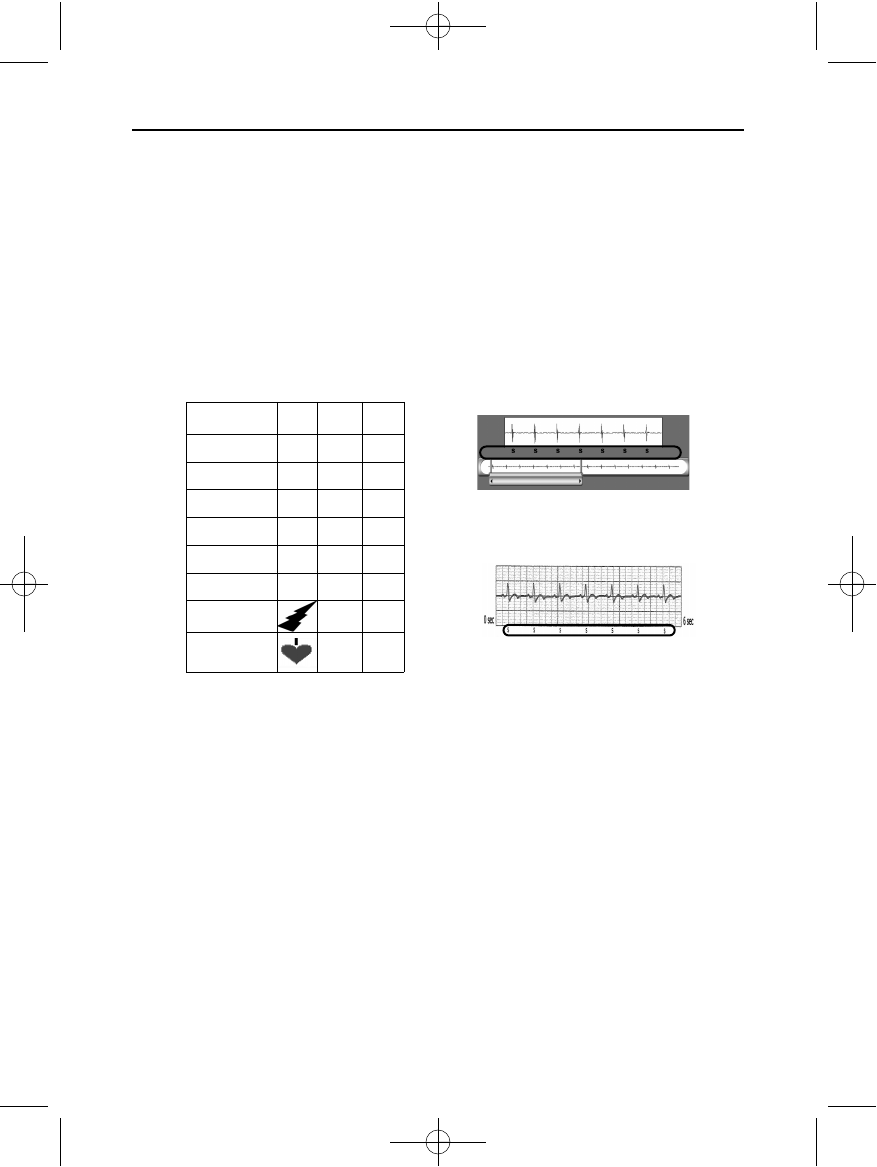
S-ECG Rhythm Strip Markers
The system provides S-ECG annotations to identify specific events during a recorded episode.
These markers are shown in Table 1; sample annotations are shown for the programmer
display (Figure 8) and the printed reports (Figure 9).
Patient Data
The device can store the following patient data, which can be retrieved and updated through
the programmer:
• Patient’s name
• Physician’s name and contact information
• Device and electrode identification information (model and serial numbers) and
implant date
• Notes up to 50 characters
Table 1: S-ECG Rhythm Strip Markers
Description Marker
Display
Screen
Printed
Reports
Charging CX3
Sensed Beat S3 3
Noisy Beat N3 3
Paced Beat P3 3
Tachy Detection T3 3
Discard Beat •3 3
Shock 3 3
Return to NSR X3
Figure 8: Display Screen Markers
Figure 9: Printed Report Markers
102098 004 rev a.qxp 12/2/2008 7:43 AM Page 25
26
SQ-RX PULSE GENERATOR
S-ICD System Magnet Model 4520
The Cameron Health magnet is a nonsterile accessory used to inhibit the delivery of therapy
from the device. Placing the magnet against the skin directly over the implanted device
(Figure 10) will temporarily inhibit rhythm detection, abort high-voltage capacitor charging
and post-shock pacing. Removal of the magnet will return the device to normal operation. If
the magnet is applied during an episode, the episode will not be stored in the device memory.
SQ-RX PULSE GENERATOR OPERATION
Figure 10: Magnet Model 4520
Magnet
Placement
PP
102098 004 rev a.qxp 12/2/2008 7:43 AM Page 26
27
SQ-RX PULSE GENERATORSQ-RX PULSE GENERATOR USING THE SQ-RX GENERATOR
This section presents the information necessary for implanting and testing the S-ICD System,
including:
• Implanting the SQ-RX Pulse Generator (the “device”)
• Implanting the Q-TRAK Subcutaneous Electrode (the “electrode”) using the
Q-GUIDE Subcutaneous Electrode Insertion Tool (the “EIT”)
• Setting up and testing the device using the Q-TECH Programmer (the
“programmer”). Refer to the Q-TECH Programmer User’s Manual for additional
information.
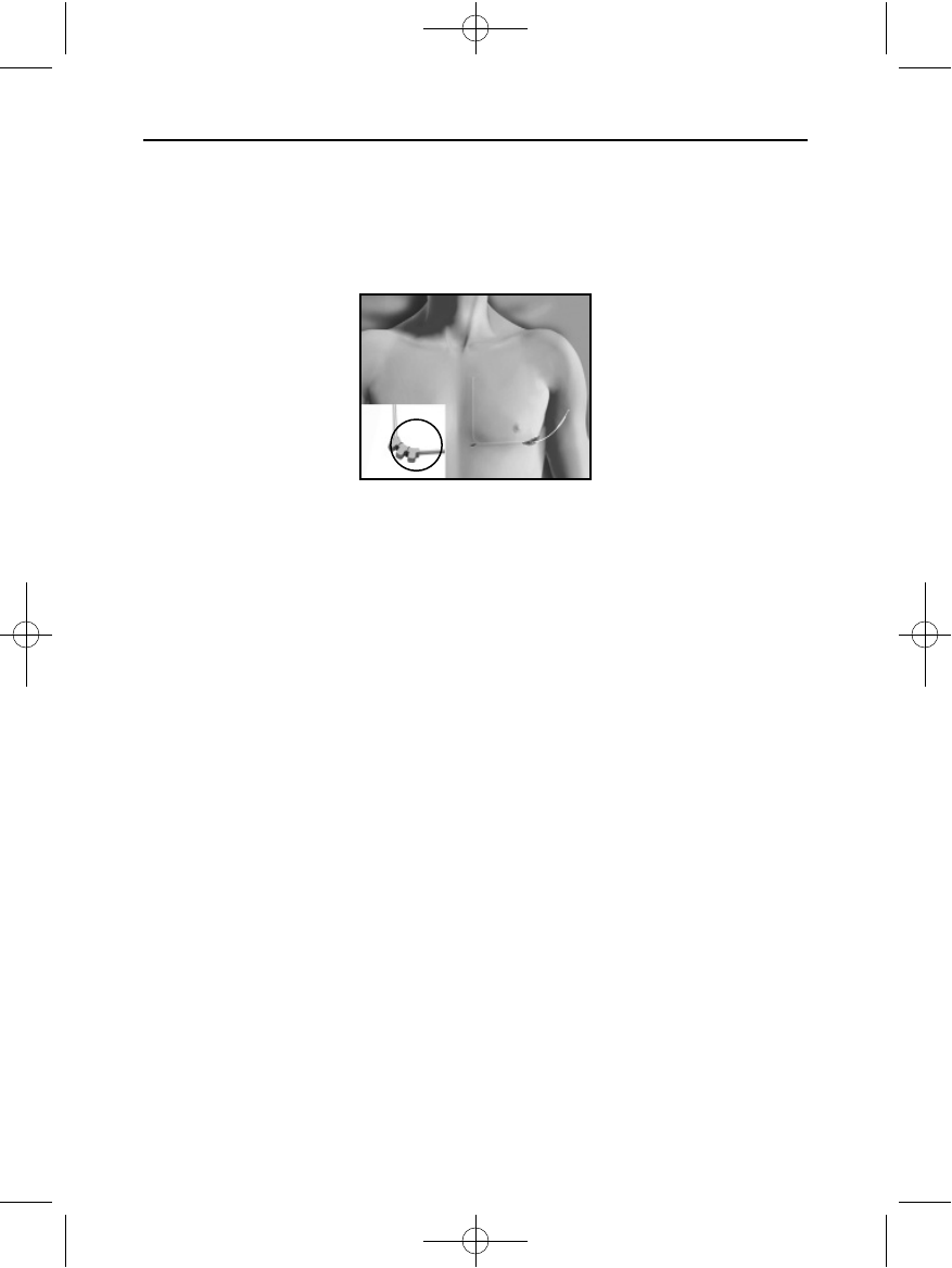
Implanting the S-ICD System
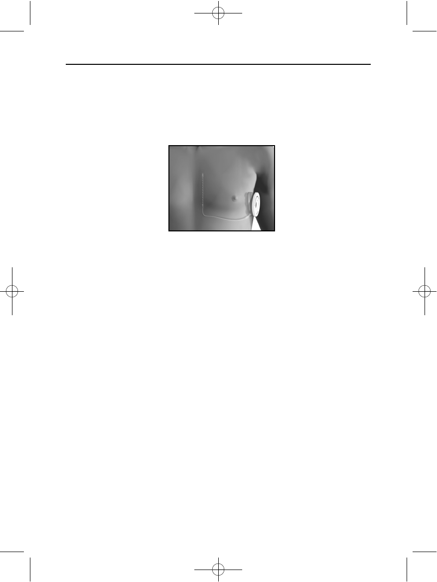
The device and electrode are implanted subcutaneously in the left thoracic region (Figure
11). The EIT is used to create the subcutaneous tunnel in which the the electrode is
inserted.
Creating the Device Pocket
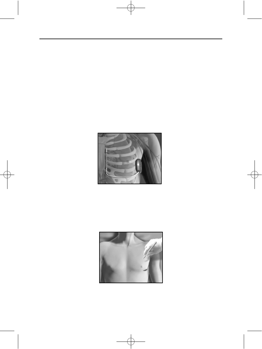
The device is implanted in the left lateral thoracic region. To create the device pocket, make
an incision such that the device can be placed in the vicinity of the left 5th and 6th
intercostal spaces and near the mid-axillary line (Figure 12). This can be accomplished by
making an incision along the inframammary crease.
Figure 12: Creating the device pocket
Figure 11: Placement of the S-ICD System
102098 004 rev a.qxp 12/2/2008 7:44 AM Page 27
28
SQ-RX PULSE GENERATORSQ-RX PULSE GENERATOR USING THE SQ-RX GENERATOR
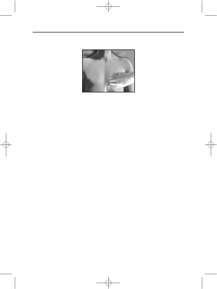
Implanting the Q-TRAK Subcutaneous Electrode
There are two methods for implanting the electrode, referred to as the “Pull/Pull” and the
“Pull/Push” techniques. The electrode tunneling is facilitated by the use of the Q-GUIDE
model 4010 and/or 4020 Subcutaneous Electrode Insertion Tool.
Pull/Pull Implant
1. Make a small (approximately 1 cm) lateral incision 1 - 2 cm to the left and 1 cm superior
to the xiphoid
2. Insert the distal tip of the EIT at the xiphoid incision and tunnel laterally until the distal
tip emerges at the device pocket (Tunnel 1).
Note: The EIT is malleable and can be curved to match the patient’s anatomical profile.
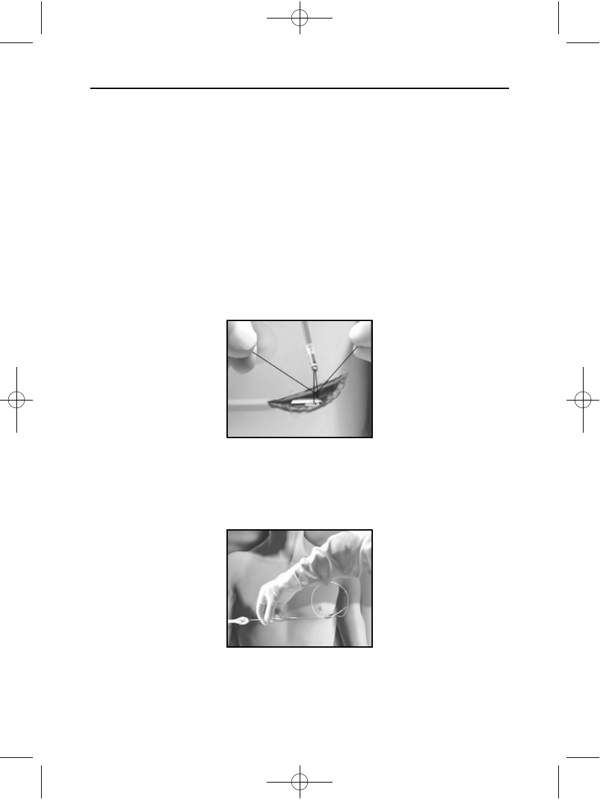
3. Using conventional suture material, tie the distal end of the electrode to the EIT
creating a loop knot that allows for free motion of both tips (Figure 13).
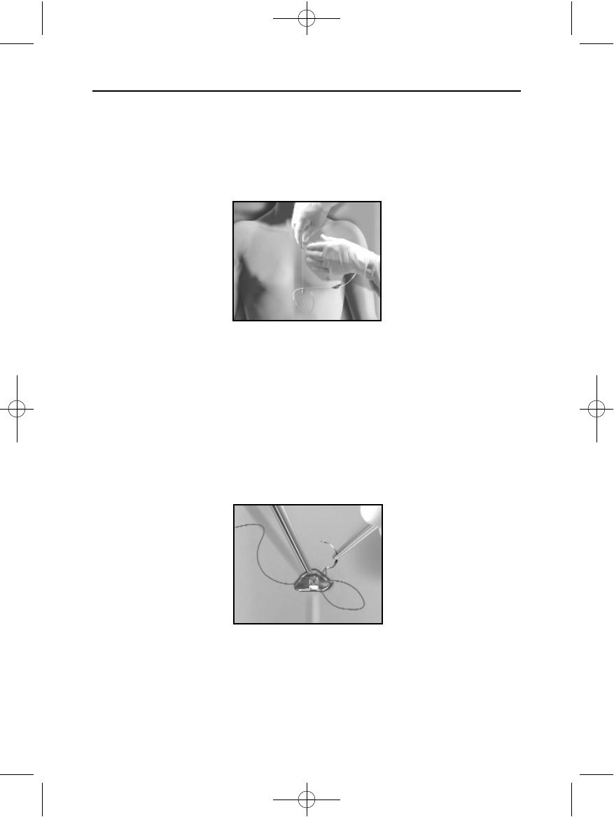
4. With the electrode attached, carefully pull the EIT back through the tunnel to the
xiphoid incision until the electrode emerges (Figure 14).
Note: Do not use surgical instruments to advance the electrode.
Figure 14: Tunneling the electrode to the xiphoid incision
Figure 13: Connecting distal end of electrode to the EIT
II
102098 004 rev a.qxp 12/2/2008 7:44 AM Page 28
29
SQ-RX PULSE GENERATORSQ-RX PULSE GENERATOR USING THE SQ-RX GENERATOR
5. Once the distal tip of the electrode is pulled through the tunnel, cut and discard the
suture loop that connects the electrode to the EIT.
6. Make a second incision approximately 14 cm superior to the xiphoid incision and
approximately 2 cm to the left of the sternal midline.
7. Insert the distal tip of the EIT into the new incision and tunnel subcutaneously in the
caudad direction to the lower xiphoid incision (Tunnel 2, Figure 15).
8. Using conventional suture material, tie the distal end of the electrode to the EIT,
creating a loop knot that allows for free motion of both tips.
9. With the electrode attached, carefully pull the EIT back through the tunnel until the
electrode’s distal tip emerges at the upper sternal incision. The electrode should be
parallel to the sternum, approximately 2 cm to the left of the sternal midline.
10. Cut and discard the suture material.
11. Using conventional suture material, anchor the electrode through the anchor hole at the
distal tip to the subcutaneous tissue to prevent possible device migration (Figure 16).
Note: If there is excess electrode body at the xiphoid incision, pull it through the tunnel
to the device pocket.
Figure 15: Tunneling in the caudad direction
Figure 16: Anchoring the distal electrode tip
II
102098 004 rev a.qxp 12/2/2008 7:44 AM Page 29
30
SQ-RX PULSE GENERATORSQ-RX PULSE GENERATOR USING THE SQ-RX GENERATOR
12. Optional: Secure a suture sleeve to the electrode at least 1 cm away from the proximal
sensing electrode using the pre-formed grooves. Verify that the suture sleeve is stable
with no slippage by grasping the suture sleeve with the fingers and trying to move the
electrode in either direction. Anchor the electrode by suturing the suture sleeve to the
subcutaneous tissue at the xiphoid incision (Figure 17).
13. To dispose of the EIT, return the used product to the original package, then dispose in a
biohazard container.
Pull/Push Implant
1. Make a small (approximately 1 cm) lateral incision 1 - 2 cm to the left and 1 cm superior
to the xiphoid.
2. Insert the distal tip of the EIT at the xiphoid incision and tunnel laterally until the distal
tip emerges at the device pocket (Tunnel 1).
Note: The EIT is malleable and can be curved to match the patient’s anatomical
profile.
3. Using conventional suture material, tie the distal end of the electrode to the EIT,
creating a loop knot that allows for free motion of both tips (Figure 13).
4. With the electrode attached, carefully pull the EIT back through the tunnel to the
xiphoid incision until the electrode emerges (Figure 14).
Note: Do not use surgical instruments to advance the electrode.
5. Once the distal tip of the electrode is pulled through the tunnel, cut and discard the
suture loop that connects the electrode to the EIT.
6. Place a 12 French peel-away introducer sheath over the Model 4020 EIT’s shaft and
secure to the luer-lock ring.
Figure 17: Secure the electrode with a suture sleeve at the xiphoid incision
I
102098 004 rev a.qxp 12/2/2008 7:44 AM Page 30
31
SQ-RX PULSE GENERATORSQ-RX PULSE GENERATOR USING THE SQ-RX GENERATOR
7. Starting at the xiphoid incision, create a cephalad tunnel (Tunnel 2) approximately 2 cm
to the left of the sternal midline (Figure 18).
8. Once the EIT is fully inserted in Tunnel 2, unlock the sheath from the luer-lock hub.
Carefully withdraw the EIT while leaving the sheath in place.
9. Insert the distal tip of the electrode into the sheath and push through until the
electrode’s distal tip is in the desired location, approximately 14 cm superior to the
xiphoid incision.
10. Stabilize the electrode’s position during sheath removal by applying manual pressure
over the electrode’s distal tip. Grasp the tabs of the sheath and split while maintaining
the implanted electrode position.
11. Secure a suture sleeve to the electrode at least 1 cm away from the proximal sensing
electrode. Verify that the suture sleeve is stable with no slippage by grasping the suture
sleeve with the fingers and trying to move the electrode in either direction. Anchor the
electrode by suturing the suture sleeve to the subcutaneous tissue at the xiphoid incision
(Figure 17).
12. Optional: Make a second incision at the point where the electrode distal tip anchor hole
resides. Using conventional suture material, anchor the distal tip of the electrode
through the anchor hole to the subcutaneous tissue to prevent possible device migration
(Figure 16).
13. To dispose of the EIT, return the used product to the original package, then dispose in a
biohazard container.
Connecting the Electrode to the Device
Note: Avoid allowing blood or other body fluids to enter the connector port in the
device header. If blood or other body fluids inadvertently enter the connector port, flush
with sterile water.
Note: Do not implant the device if the set screw seal plug appears to be damaged.
Figure 18: Creating a cephalad tunnel parallel to the sternal line using
the EIT & 12 Fr sheath
II
102098 004 rev a.qxp 12/2/2008 7:44 AM Page 31
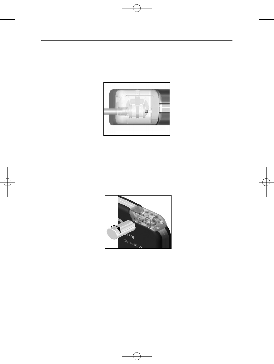
1. Insert the proximal end of the electrode into the connector port until it will no longer
advance.
Note: Do not use surgical instruments to advance the electrode.
2. Ensure that the electrode pin is protruding past the innermost connector ring in the
connector cavity (Figure 19).
3. Use the torque wrench to tighten the set screw in a clockwise motion (Figure 20). The
torque wrench is designed to apply the proper amount of force to the set screw. Tighten
the set screw until the wrench ratchet clicks.
Note: When connecting the electrode to the device, use only the tools provided in the
device tray. Failure to use the supplied tools may result in damage to the set screw.
Retain the tools until all testing procedures are complete and the device is implanted.
4. Gently tug on the electrode body to confirm a secure connection.
5. Insert the device into the subcutaneous pocket, with any excess electrode placed
underneath the device.
32
SQ-RX PULSE GENERATORSQ-RX PULSE GENERATOR USING THE SQ-RX GENERATOR
Figure 19: Proper position for inserted electrode pin
Figure 20: Using torque wrench to tighten set screw
I
102098 004 rev a.qxp 12/2/2008 7:44 AM Page 32
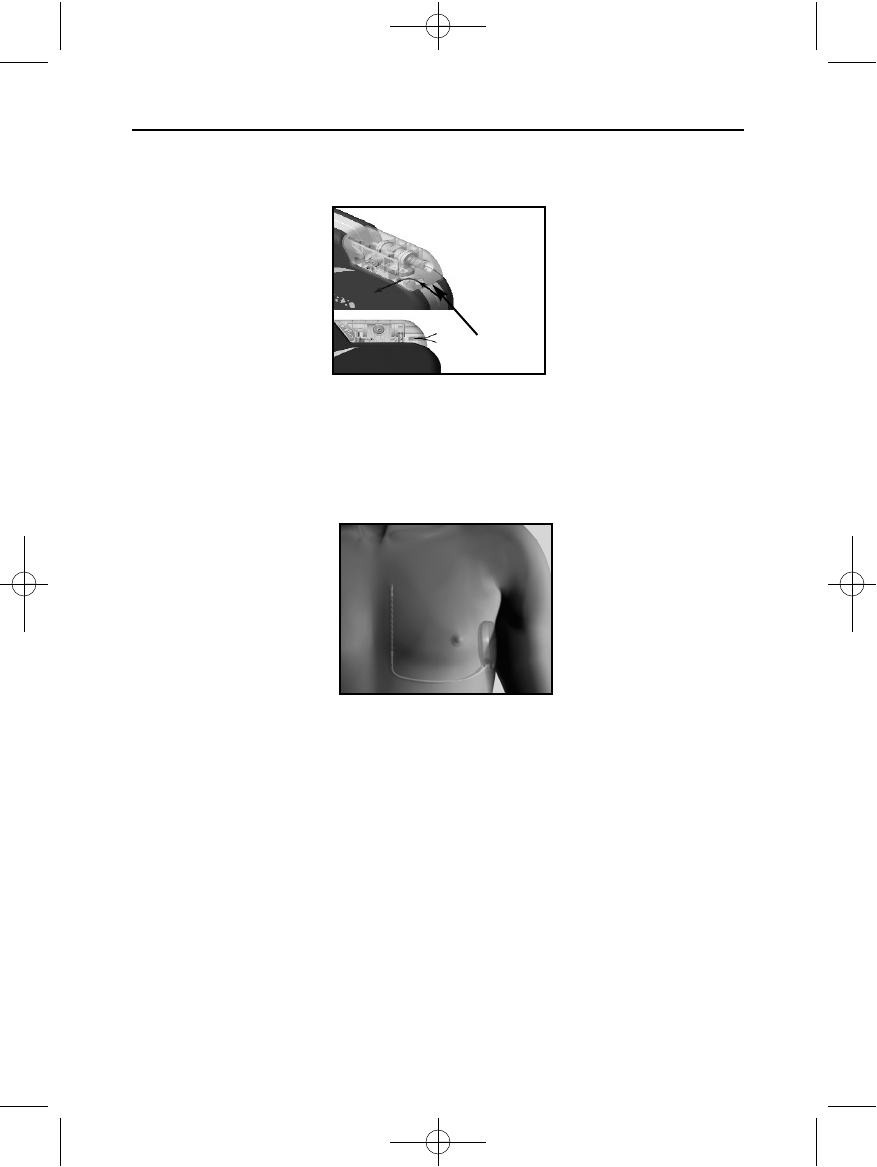
6. Anchor the device to subcutaneous tissue to prevent possible migration using
conventional suture material. A suture hole is provided in the header for this purpose
(Figure 21).
7. Refer to the Q-TECH Programmer User’s Manual for set-up instructions and/or induction
testing.
Note: Initial set-up is recommended at implant.
8. After device set-up, close all incisions using standard suture protocol (Figure 22).
Setting Up the SQ-RX Pulse Generator
A brief Setup process must be completed before the device can deliver manual or automatic
therapy. This process can be performed automatically or manually during the implant
procedure, although Automatic Setup is recommended.
During Setup, the system automatically:
• Confirms entry of the subcutaneous electrode model and serial numbers
• Measures the shock electrode impedance
• Optimizes the sense electrode configuration
• Optimizes the gain selection
• Provides an option to acquire a reference NSR template
Instructions for completing this process can be found in the Q-TECH Programmer User’s
Manual.
33
SQ-RX PULSE GENERATORSQ-RX PULSE GENERATOR USING THE SQ-RX GENERATOR
Figure 21: Anchoring the device using header suture holes
Figure 22: System placement after closure of all incisions
102098 004 rev a.qxp 12/2/2008 7:44 AM Page 33

Post Implant Follow-Up Procedures
During a follow-up procedure, it is recommended that the location of the electrode be
periodically verified by palpation and or X-ray. When device communication with the
programmer is established, the programmer automatically notifies the physician of any
unusual conditions. Refer to the Q-TECH Programmer User’s Manual for more information.
Patient management and follow-up are at the discretion of the patient’s physician, but are
recommended at least once a year and should be more frequent when the device is
approaching end-of-life.
Explanting the S-ICD System
If a device explant is required, observe the following guidelines:
1. Use the programmer to ensure the device is programmed to Therapy Off.
2. Use a sterile no. 2 wrench to disconnect the electrode from the device.
3. Return the explanted device to Cameron Health, Inc. along with a completed
Explant/Complication Reporting Form. Contact your local Cameron Health
representative or Customer Service Department for instructions and return packaging.
34
SQ-RX PULSE GENERATORSQ-RX PULSE GENERATOR USING THE SQ-RX GENERATOR
102098 004 rev a.qxp 12/2/2008 7:44 AM Page 34

Federal Communications Commission (FCC) Compliance
This transmitter is authorized by rule under the Medical Implant Communications Service
(part 95 of the FCC Rules) and must not cause harmful interference to stations operating in
the 400.150 - 406.00 MHz band in the Meteorological Aids (i.e., transmitters and receivers
used to communicate weather data), the Meteorological Satellite, or the Earth Exploration
Satellite Services and must accept interference that may be caused by such aids, including
interference that may cause undesired operation. This transmitter shall be used only in
accordance with the FCC Rules governing the Medical Implant Communications Service.
Analog and digital voice communications are prohibited. Although this transmitter has been
approved by the Federal Communications Commission, there is no guarantee that it will not
receive interference or that any particular transmission from this transmitter will be free
from interference.
FCC ID SDYCHI1010
1999/5/EC Compliance (R&TTE Directive)
The S-ICD System contains radio equipment in the frequency range 402 MHz to 405 MHz for
ultra low power active medical implants. The radio equipment in the S-ICD System complies
with the applicable harmonized standards and essential requirements of the R&TTE
Directive.
35
SQ-RX PULSE GENERATOR CCOOMMPPLLIIAANNCCEE
102098 004 rev a.qxp 12/2/2008 7:44 AM Page 35
36
SQ-RX PULSE GENERATOR
Specifications
Specifications provided at 37° C ± 3° C, and assume a 75W(± 1%) load unless noted otherwise.
*Normal use is defined as three full-energy capacitor charges per year.
Table 2: Physical Characteristics
Dimensions:
Height x Width x Depth
78.2 mm x 65.5 mm x 15.7 mm
Mass 145 gm
Volume 69.9 cc
Longevity Normal Use*: 5 years
ERI to EOL 3 months therapy if no more than 5 maximum-energy
charges/shocks occur.
Radiopaque ID in Device Header CH1010
SQ-RX Pulse Generator Storage
and Shipping Range
Temp: 0° F or -18° C / +131° F or +55° C
Defibrillation/Pace/
Sense Ports
Cameron Health Proprietary Tripolar Connector
Pulse Generator Casing Material Hermetically Sealed Titanium, Coated With Titanium
Nitride
Connector Block Header Implantation Grade Polymer
Battery Lithium Manganese Dioxide
SQ-RX PULSE GENERATOR ADDITIONAL INFORMATION
102098 004 rev a.qxp 12/2/2008 7:44 AM Page 36
37
SQ-RX PULSE GENERATORSQ-RX PULSE GENERATOR ADDITIONAL INFORMATION
Table 3: Programmable Parameters
Parameter Programmable Values Nominal
(as shipped)
Shock Zone 170 bpm - 250 bpm (steps of 10 bpm) 200 bpm
Conditional
Shock Zone
Off, 170 bpm - 240 bpm
If On, at least 10 bpm less than Shock Zone
Off
S-ICD System Therapy Off, Manual, Auto Therapy Off
Post-shock Pacing On, Off Off
Sensing Configuration Primary: Proximal electrode ring to device.
Secondary: Distal electrode ring to device.
Alternate: Distal electrode ring to proximal
electrode ring.
Primary
Max Sensing Range x1 (± 4 mV)
x2 (± 2 mV)
x1
Manual Shock 10 - 80 J (in steps of 5 J) 80 J
Smart Charge Resets to nominal
Polarity Standard: Phase 1 Coil (+)
Reverse: Phase 1 Coil (-)
Table 4: Non-Programmable Parameters (Shock Therapy)
Parameter Value
Shock Therapy
Delivered Energy 80 J
Shock Tilt (%) 50%
Waveform Type Biphasic
Maximum Number of Shocks per episode 5 shocks
Sync Time Out 1 sec
Shock Sync Delay 60 ms
Post-Shock Blanking Period 1600 ms
102098 004 rev a.qxp 12/2/2008 7:44 AM Page 37
38
SQ-RX PULSE GENERATORSQ-RX PULSE GENERATOR ADDITIONAL INFORMATION
Table 5: Non-Programmable Parameters (Post-Shock Pacing)
Parameter Value
Post-Shock Pacing
Rate 50 ppm
Pacing Output 200 mA
Pulse Width 7.6 ms phase 1, 7.6 ms phase 2
Waveform Biphasic
Polarity (of the first phase) Standard Phase 1 Coil (+)
Mode Inhibited Pacing
Duration 30 s
Post-Pace Blanking Period/Refractory Period 550 ms (precedes refractory period)
Runaway Protection 120 ppm
Table 6: Non-Programmable Parameters (Detection/Rhythm Discrimination, Fibrillation
Induction, Shock Electrode, Capacitor Reform Schedule)
Parameter Value
Detection/Rhythm Discrimination
X/Y for Initial Detection 18/24 intervals
X/Y for Redetection 14/24 intervals
Confirmation Before Shock 3 consecutive tachy intervals
Refractory Period Fast 160 ms, Slow 200 ms
Fibrillation Induction
Frequency 50 Hz
Output 200 mA
Time out After Activation 10 sec
102098 004 rev a.qxp 12/2/2008 7:44 AM Page 38
39
SQ-RX PULSE GENERATORSQ-RX PULSE GENERATOR ADDITIONAL INFORMATION
Table 8: Magnet Response
Parameter Value
Shelf Mode No Response
Therapy On Arrhythmia detection and response are suspended. Beeper
sounds for 60 seconds to indicate sensing is occurring.*
Therapy Off Beeper sounds for 60 seconds to indicate sensing is
occurring.*
Table 7: Episode Data Parameters
Parameter Value
Episode Data Parameters
Treated Episodes 24 stored
Untreated Episodes 20 stored
Maximum Length per S-ECG Episode 128 seconds
Captured S-ECG Report 5 Captured S-ECG at 12 seconds each
* Beeper Sounds – Beeper will sound for 60 seconds to indicate sensing is occurring or until the magnet is
removed, whichever occurs first.
Capacitor Reform Schedule
Automatic Capacitor Reformation Interval Approximately 4 months*
Internal Warning System
High Impedance > 400 Ohms
Maximum Charge Time out 44 seconds
Table 6: Continued
* Reform can be delayed if capacitor was charged due to sustained/nonsustained arrhythmia in past 4 months
102098 004 rev a.qxp 12/2/2008 7:44 AM Page 39
40
SQ-RX PULSE GENERATORSQ-RX PULSE GENERATOR ADDITIONAL INFORMATION
Specifications Description
Shape Circular
Size Approximate Diameter 2.7 in/7.0 cm
Thickness 0.5 in/1.3 cm
Content Ferrous Alloys coated with epoxy
Field Strength 90 gauss minimum when measured at a
distance of 1.5 in/3.8 cm from magnet surface.
Table 10: Model 4520 S-ICD System Magnet Specifications
Patient Information (Stored Data)
Patient Name
Physician Name
Physician Contact Information
Device Model Number
Device Serial Number
Electrode Model Number
Electrode Serial Number
Notes up to 50 characters
Table 9: Stored Patient Information
102098 004 rev a.qxp 12/2/2008 7:44 AM Page 40
41
SQ-RX PULSE GENERATORSQ-RX PULSE GENERATOR ADDITIONAL INFORMATION
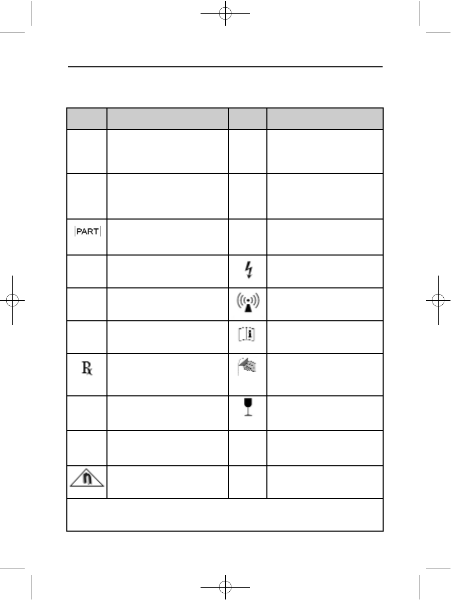
Table 11: Packaging Symbols
Definitions of Package Label Symbols
Symbol Definition Symbol Definition
ISterilized by Ethylene Oxide
Gas - Product is sterilized using
ethylene oxide gas.
NDate of Manufacture - Date
on which the device was
manufactured. Date shown as
YYYY/MM/DD.
PLimitation European Community
Represented - Authorized
Representative in the EU
community.
HUse By - Use by the indicated
date. Date shown as
YYYY/MM/DD.
Part Number - Component
number. lStorage Temperature - Product
is stored with temperature
limitations.
gLot Number - Batch code. Hazardous Voltage - Caution -
dangerous voltage.
hReference Number - Finished
goods stock number.
Radio - Radio frequency.
fSerial Number - Serial number
of the device.
Instructions - Consult
instructions before use.
Intended Use Symbol - In the
USA Federal Law restricts the
device to sale by or on the order
of a physician.
Open Here - Symbol showing
how to open the package.
DNon-reusable - Single use only. Fragile: Handle with Care -
Transport and store with care.
MManufacturer - Place at which
the device is manufactured. pKeep Dry - Ship and store in a
dry place.
Magnetic Field - To warn of a
magnetic field.
CReserved for CE mark
FCC ID SDYCHI1010 - Federal Communications Commission - Identifier serial
number.
102098 004 rev a.qxp 12/2/2008 7:44 AM Page 41

42
SQ-RX PULSE GENERATORSQ-RX PULSE GENERATOR APPENDIX
S-ICD System And Pacemaker Interaction
Interaction between the S-ICD System and a temporary or permanent pacemaker is
possible and can interfere with the identification of tachyarrhythmias in several ways.
• If the pacing pulse is detected, the S-ICD System may not adjust sensitivity
appropriately, fail to sense a tachyarrhythmia episode and/or not deliver
therapy.
• Pacemaker sensing failure, lead dislodgment or failure to capture could result
in the sensing of two asynchronous sets of signals by the S-ICD System, causing
the rate measurement to be faster, and may result in delivery of unnecessary
shock therapy.
• Conduction delay may cause the device to oversense the evoked QRS and T-wave
resulting in unnecessary shock therapy.
Pacemakers that employ impedance checks like MV sensors and unipolar pacemakers
are contraindicated for use with the S-ICD System. This includes pacemakers that
revert or reset to the unipolar pacing mode.
The following test procedure aids in determining S-ICD System and pacemaker
interaction.
Note: External defibrillation equipment should be available for immediate use during
the implantation procedure as well as during testing and follow-up.
Note: If implanting a pacemaker with an existing S-ICD System, program the S-ICD
System to Therapy Off.
During the testing procedure, program the pacemaker output to maximum and
asynchronously pace in the pacing mode to which the pacemaker will be permanently
programmed (e.g., DOO for most dual-chamber modes and VOO for single-chamber
modes).
1. Follow the patient screening tool procedure to assure that the patient’s paced S-ECG
signal passes the criteria.
2. Program the S-ICD System to Therapy On and complete the set-up procedure.
3. Observe the S-ECG for any pacing artifacts. If any pacing artifacts are present and larger
in amplitude than the R-wave, use of the S-ICD System is not recommended.
4. Induce the tachyarrhythmia and observe the S-ECG markers to determine appropriate
detection and delivery of therapy.
5. If inappropriate sensing is observed as a result of the device sensing the pacing artifact,
reduce the pacemaker’s pacing output and retest.
In addition, pacemaker operation may be affected by the S-ICD System therapy delivery. This
could alter the pacemaker’s programmed settings or damage the pacemaker. In this situation,
102098 004 rev a.qxp 12/2/2008 7:44 AM Page 42

most pacemakers will conduct a memory check to determine if the parameters for safe
operation were affected. Further interrogation will determine if programmed pacemaker
parameters are altered. Refer to the manufacturer’s pacemaker manual for implantation
and explantation considerations.
Limited Warranty
Cameron Health, Inc. warrants to Purchaser, that for a period of five (5) years or sixty (60)
months commencing with the date of implantation of the SQ-RX Pulse Generator (“the
Product”), that should the Product fail to function in accordance with Cameron Health, Inc.’s
published specifications, due to a defect in materials or workmanship, Cameron Health, Inc.
will as Purchaser’s sole remedy and Cameron Health, Inc.’s sole liability:
1. If within the three (3) year period, or 36 months, commencing with the date of
implantation, Cameron Health, Inc. will provide a functionally comparable
replacement defibrillator at no charge.
2. If after the three (3) year period from month 37 and until five (5) years or 60
months from the date of implant, Cameron Health, Inc. will provide a credit to
the Purchaser for a replacement product in an amount equal to 50% of the
original purchase price reduced on a pro rata basis over this two year period.
The prorated credit amount will be calculated on a monthly basis over this
twenty-four month period.
In no event will any warranty credit issued hereunder exceed the original purchase price of
the Product or the purchase price of the replacement Product.
The Product is designed as a single use device and must not be resterilized. Any
resterilization voids the warranty.
OTHER LIMITATIONS ON THE TERM OF THIS LIMITED WARRANTY ARE PROVIDED WITH
THE SALES DOCUMENTS AND ARE CONSIDERED AN INTEGRAL PART OF THIS LIMITED
WARRANTY, AS ARE THE WARNINGS CONTAINED IN THE PRODUCT LABELING. CONTACT
YOUR LOCAL CAMERON HEALTH, INC. REPRESENTATIVE OR THE CAMERON HEALTH,
INC. CUSTOMER SERVICE DEPARTMENT TO OBTAIN THIS INFORMATION AND TO OBTAIN
INFORMATION ON HOW TO PROCESS A CLAIM UNDER THIS LIMITED WARRANTY.
To qualify for this limited warranty, the following conditions must be met:
•The Product must be implanted prior to the “USE BEFORE DATE” in
conjunction with a Cameron Health, Inc. electrode.
•The replaced Product must be returned to Cameron Health, Inc. within
thirty (30) days after explant and shall be the property of Cameron
Health, Inc.
•The device must be clean and free from any bodily residue before
returning.
43
SQ-RX PULSE GENERATORSQ-RX PULSE GENERATOR APPENDIX
102098 004 rev a.qxp 12/2/2008 7:44 AM Page 43

102098 004 rev a.qxp 12/2/2008 7:44 AM Page 44
102098 004 rev a.qxp 12/2/2008 7:44 AM Page 45
Cameron Health, Inc.
905 Calle Amanecer
Suite 300
San Clemente, CA 92673
USA
Tel: 1 949 498 5630
Free: 1 877 SICD 411
1 877 742 3411
Fax: 1 949 498 5932
URL: www.cameronhealth.com
Cameron Health BV
World Trade Center
Nieuwe Stationsstraat 10
6811 KS Arnhem
The Netherlands
Tel: 31 26 3550260
Free: 800 SICD 4 YOU
800 7423 4 968
Fax: 31 26 3550269
URL: www.cameronhealth.com
PN 102098-004 Rev B 2008/09
102098 004 rev a.qxp 12/2/2008 7:44 AM Page 46