Canam Technology M4BBDA8 Power Amplifier User Manual
Canam Technology, Inc Power Amplifier Users Manual
Users Manual

CANAM TECHNOLOGY, Inc.
MARK-IV BROADBAND AMPLIFIERS
USER’S MANUAL
REVISION 3
Jan 2006

MARK-IV BROADBAND AMPLIFIERS
User’s Manual
2 / 11
REV3 01/25/06
T
TA
AB
BL
LE
E
O
OF
F
C
CO
ON
NT
TE
EN
NT
TS
S
Section A. Introduction ......................................................................................3
Section B. GLOSSARY OF TERMS.......................................................................5
Section C. THEORY OF OPERATION ..................................................................6
Section D. SPECIFICATIONS ...............................................................................7
Section E. INSTALLATION....................................................................................8
E.1 Equipment Installation............................................................................8
E.2 Antenna Installation..............................................................................10

MARK-IV BROADBAND AMPLIFIERS
User’s Manual
3 / 11
REV3 01/25/06
Section A. Introduction
This document is the MARK-IV Broadband Amplifiers User’s Manual, intended for the
Radio Technical Personnel.
The Mark-IV Broadband Amplifiers are highly-linear devices suitable for applications in the
two-way radio and cellular UHF and 800 MHz bands.
They are intended for use in low to mid power amplification and re-amplification systems,
including land-mobile radio and cellular uni- and bi-directional signal booster systems.
These amplifiers utilize linear LDMOS power devices that provide high gain, wide dynamic
range, and excellent group delay and phase linearity.
Exceptional performance, long term reliability, and high efficiency are achieved by
employing advanced matching networks and combining techniques, EMI/RFI filters,
machined housings, and qualified components.
Models:
UHF band: M4-BBDA-U, FCC ID: TCJ-M4BBDAU
800 MHz band: M4-BBDA-8, FCC ID: TCJ-M4BBDA8
Key Features:
• Solid-state, ultra-linear design
• High reliability and ruggedness.
• Built-in high dynamic range with Automatic Level Control (ALC) circuit.
• Built-in Output Circulator
• Built-in monitoring circuits, DC signal at interface connector:
o Forward Power Detector
o Reverse Power Detector

MARK-IV BROADBAND AMPLIFIERS
User’s Manual
4 / 11
REV3 01/25/06
General Disclaimers
This manual is intended to be used with the MARK-IV Equipment only. It is not to be used
with any other equipment unless it is authorized by Canam Technology, Inc.
Canam Technology, Inc provide this document “as is” without any warranty of any kind.
This document may contain typographical errors and technical inaccuracies. Canam
Technology will not accept any liability from the use and misuse of this manual, the
information contained within, or the consequences of any actions resulting from the use
of this information.
The user can not make any modifications to the unit(s). Changes or modifications not
expressly approved by the party responsible for compliance voids the user’s authority to
operate the equipment.
Radio-Frequency Amplifiers such as the MARK-IV generate radio signals and, therefore,
electromagnetic fields. The technical personnel should have a complete understanding
of FCC CFR Title 47 sections 1.1307 and 1.1310. Recommendations are included in this
Manual, but they do not substitute the FCC guidelines.
This device may require the use of antennas for proper functioning, depending on the
application. The installation of the antennas should be performed by qualified technical
personnel. All antennas should be fixed mounted and physically secured to one
location. The people must be away from the antennas at least 1.0 meters to comply with
the RF Human Maximum Permissible Exposure limits, as long as the antenna system gain
is lower than 0 dBi. If greater gain is used the separation should be increased, please
refer to the FCC Rules.
If service should be performed on the antenna, please shut down the transmitter or lower
its power in order to comply with the maximum permissible exposure.

MARK-IV BROADBAND AMPLIFIERS
User’s Manual
5 / 11
REV3 01/25/06
Section B. GLOSSARY OF TERMS
AC: Alternating Current.
Broadband Amplifier: A device at a fixed location which automatically receives,
amplifies, and retransmits the signals received from base, fixed, mobile, and portable
stations, with no change in frequency or authorized bandwidth. All signals within the
passband of the amplifier filter are amplified.
DC: Direct Current.
Rx: Receiver or Input Port.
Tx: Transmitter or Output Port.

MARK-IV BROADBAND AMPLIFIERS
User’s Manual
6 / 11
REV3 01/25/06
Section C. THEORY OF OPERATION
The MARK-IV BROADBAND AMPLIFIERS are self contained modules having the RF Input
and Output ports via SMA-type coaxial connectors and DC plus Control signals via D-
Subminiature 9-pin connector.
These amplifiers modules must be installed on appropriate heat-sinks to dissipate the
heat they generate during normal operation (with or without input signal). It is
recommendable the Case Temperature not to exceed 50 degrees Celsius to benefit the
amplifier’s life span.
The RF Input signal is amplified by the amplifier’s gain and delivered at the RF Output
without changes in frequency, modulation or occupied bandwidth.
Pout = Pin + Gain
The MARK-IV BROADBAND AMPLIFIERS are equipped with Automatic Level Control (ALC)
circuitry to limit the output power to the factory preset level, preventing that an input
drive signal level plus the amplifier’s gain would exceed the maximum authorized output
power level. In that case, the ALC circuit will proportionally decrease the gain as
required not to exceed the preset output level. A red LED on the side of the amplifier’s
case is lit when the ALC circuit is in operation.
The amplifiers are also equipped with Input Overdrive Protection (passive “fuse-type”) to
prevent further damage of its internal stages in case of accidental very strong signals
well above the maximum input level required for normal operation.
The MARK-IV BROADBAND AMPLIFIERS requires an external DC Power Supply, typical +28
VDC. They can operate at +24 VDC with approximately 1 dB reduction on gain and
linearity performance. The current draw is less than 4 Amps at maximum output power.

MARK-IV BROADBAND AMPLIFIERS
User’s Manual
7 / 11
REV3 01/25/06
Section D. SPECIFICATIONS
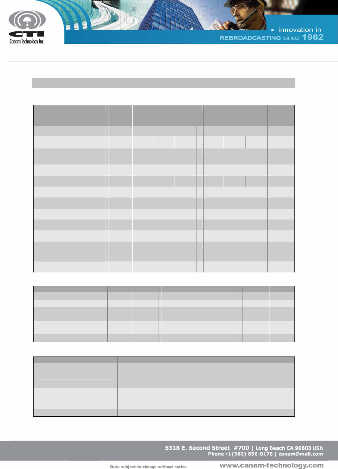
ELECTRICAL SPECIFICATIONS @ VDD=+28VDC, T=25°C, 50Ω System
UHF Band
400 – 512 MHz
800 MHz Band
806 - 870 MHz
Model M4-BBDA-U M4-BBDA-8
Parameter Symbol FL FM FH FL FM FH Unit
Maximum Operating Output
Power, limited by ALC. POP 5 15 Watt
P1dB G.C.P. P1dB 25 50 Watt
Small Signal Gain SSG 38 45 46 40 45 45 dB
Small Signal Gain Flatness ∆G ±0.5 ±0.75 dB
Input/Output VSWR S11/S22 1.5:1 typ. 1.5:1 typ. -
Harmonics H < -13 < -13 dBm
Noise Figure NF 7 typ. 7 typ. dB
Spurious Signals Spur -60 -60 dBc
Supply Current
(UHF@4W, 7-800@12W composite
power)
IDD 2 4 Amps
Operating Voltage VDD +28 +28 Volts DC
ENVIRONMENTAL CHARACTERISTICS & PROTECTIONS
Parameter Symbol Min Typ Max Unit
Operating Case Temperature Tc 0 +50 °C
Storage Temperature Tstg -40 +85 °C
Input Overdrive +6dBm for -U model,
+10 dBm for -8 model
Load VSWR @ nominal output
power Infinite @ all load phase & amplitude
Thermal Overload 85°C shutdown
Monitoring Functions
Parameter Typical Specifications
Forward Power Monitor
Continuous Analog voltage relative to forward power via RMS detector.
-U Model: FWDM: 13 - 43dBm @ 0 - 5V (200mV/dB). 28dBm output =
VFWD = 2.5VDC
-8 Model: FWDM: 17 - 47dBm @ 0 - 5V (200mV/dB)
Reverse Power Monitor Continuous Analog voltage relative to reflected power via RMS detector.
-U Model: REVM: 6 - 36dBm @ 0 - 5V (150mV/dB)
-8 Model: REVM: 12 - 42dBm @ 0 - 5V (150mV/dB)
Mute Enable: TTL “Low”. Disable: TTL “High”

MARK-IV BROADBAND AMPLIFIERS
User’s Manual
8 / 11
REV3 01/25/06
Section E. INSTALLATION
E.1 Equipment Installation
Canam Technology’s Equipment is factory configured. All setup and wiring is performed
by Canam’s Personnel. There is no need to disconnect the equipment unless the units
should be serviced.
Warning: if any module should be disconnected, it should only be performed by qualified
technical personnel.
RF-INPUT
6.370
6.173
3.039
0.433
0.098
3.320
3.123
2.865
0.575
LED
0.528
0.433
1.779
1.024
Ø0.134 THRU
4 PL
0.098
FORWARD
REVERSE
ALC ON/OFF
ALC LEVEL
REMOTE
MUTE
+VDD
+VDD
GND
GND
1
2
3
4
5
6
7
8
9
RF-INPUT
RF-OUTPUT
LED
Figure 1: MARK-IV BBDA 800 MHz-band Mechanical Outline (Units in inches)

MARK-IV BROADBAND AMPLIFIERS
User’s Manual
9 / 11
REV3 01/25/06
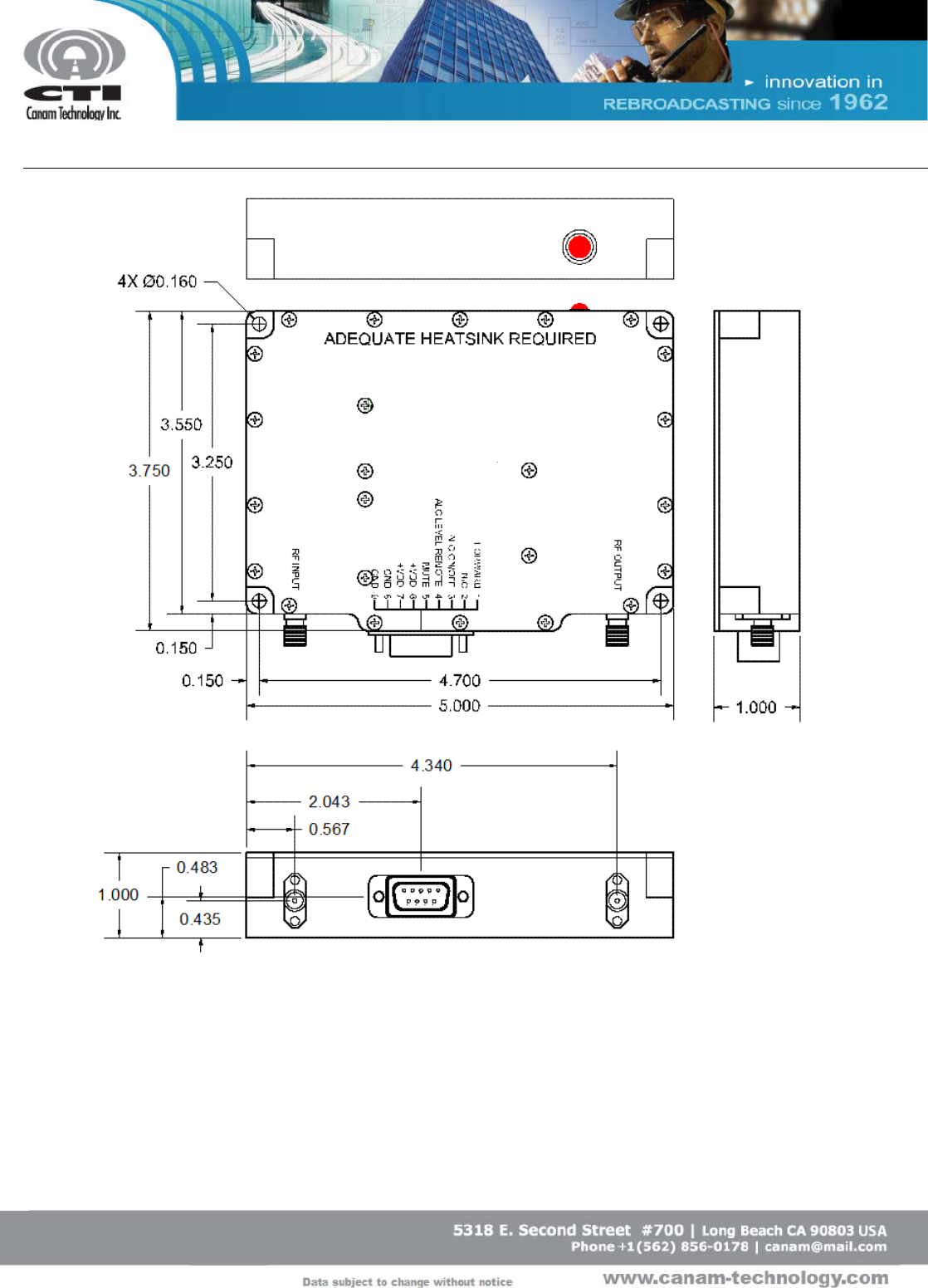
Figure 2: MARK-IV BBDA UHF-band Mechanical Outline (Units in inches)

MARK-IV BROADBAND AMPLIFIERS
User’s Manual
10 / 11
REV3 01/25/06
E.2 Antenna Installation
The Input antenna and output antenna are not included with this equipment.
Nevertheless, if this device is used in an application that requires direct connection to an
antenna, Canam Technology recommends following the FCC guidelines for its
installation:
• Antenna Installation should be performed by qualified technical personnel.
• The installations instructions are for the purpose of complying with FCC RF
Exposure and are not optional.
• All antennas (Donor and Service) should be fixed mounted and physically
secured to one location.
• Non-building mounted donor antennas must be greater than 10 meters above
ground.
• Minimum Separation to any body’s part of any person is 1 meter, as long as the
System Antenna Gain is lower than 0 dBi.
• The Maximum System Antenna Gain should be as follows for each model:
o For MARK-IV 800-band model M4-BBDA-8: G < 0 dBi.
o For MARK-IV UHF-band model M4-BBDA-U: G < -3 dBi.

MARK-IV BROADBAND AMPLIFIERS
User’s Manual
11 / 11
REV3 01/25/06
(This page is intentionally left blank)