Canam Technology M4DBDA8 MARK-IV Digital Class-A Signal Booster User Manual UHF CHANNELIZED OUTPUT LIMIT CONTROL
Canam Technology, Inc MARK-IV Digital Class-A Signal Booster UHF CHANNELIZED OUTPUT LIMIT CONTROL
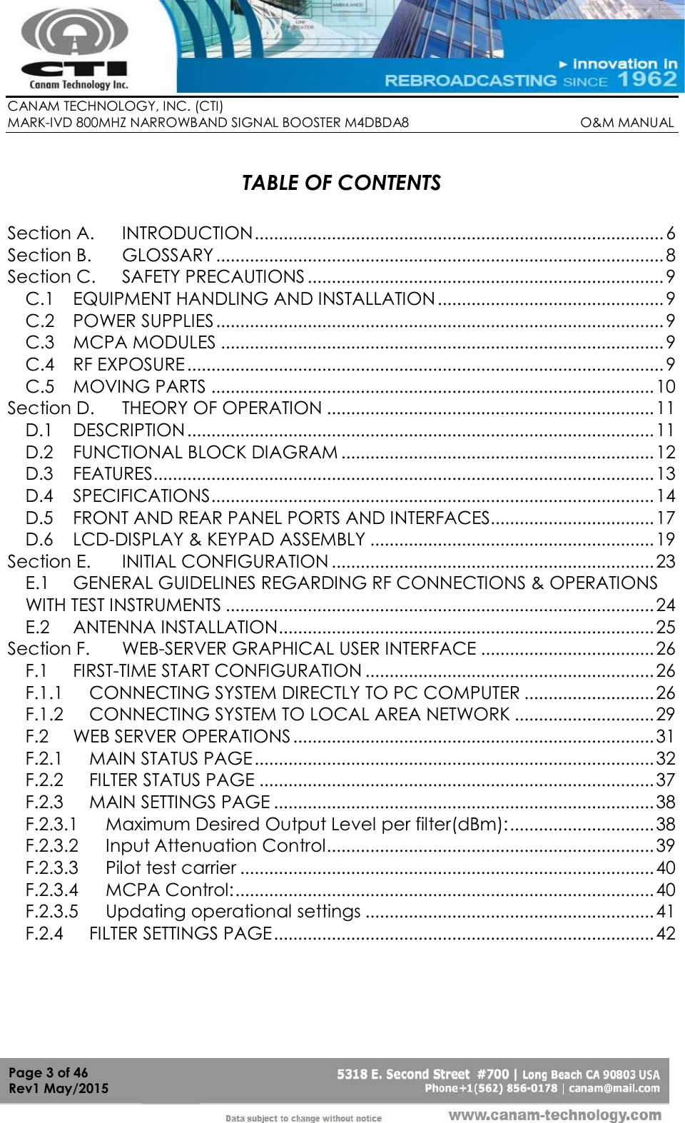
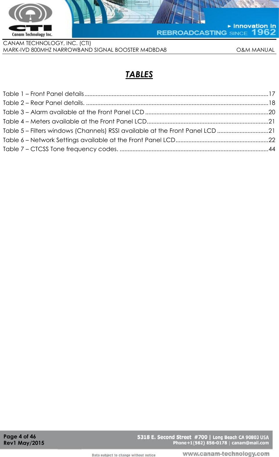
Contents
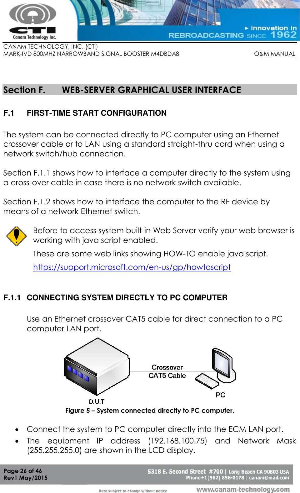
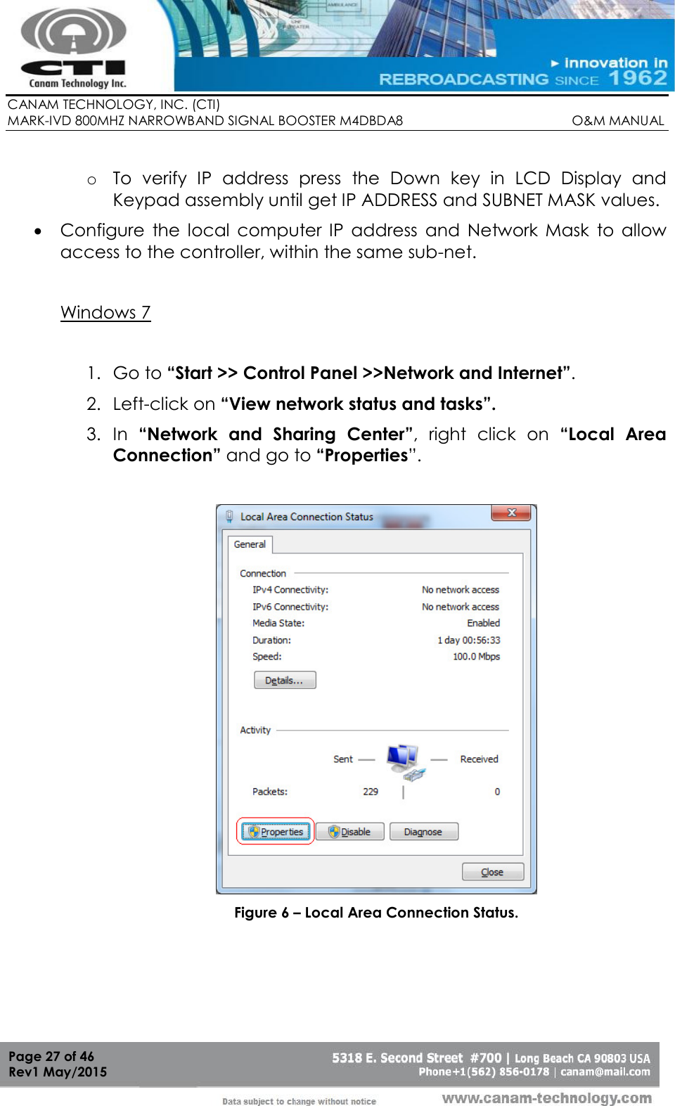
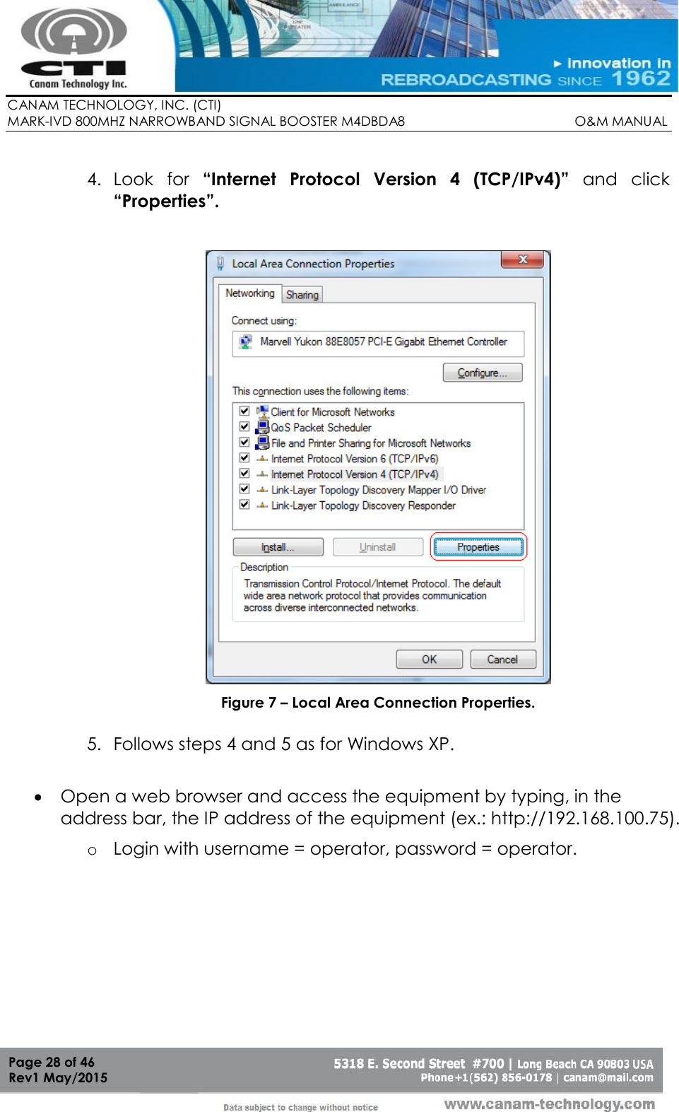
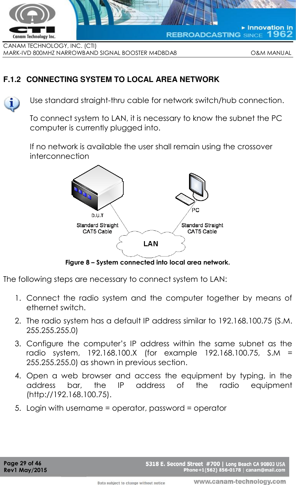
- 1. Operation and Maintenance Manual Rev
- 2. User Manual Rev
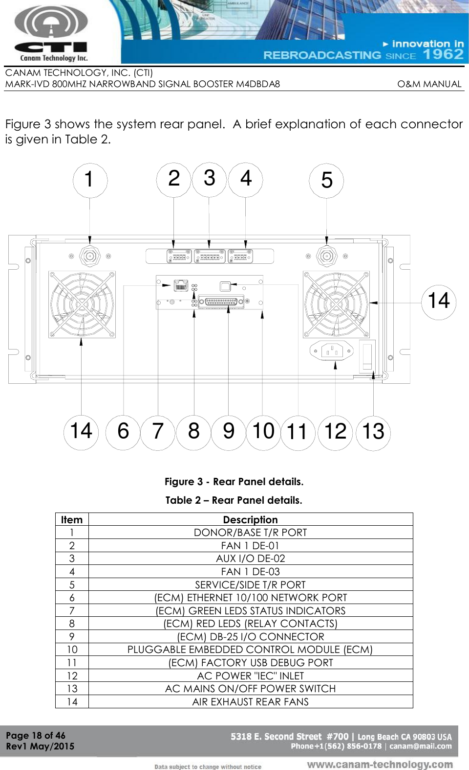
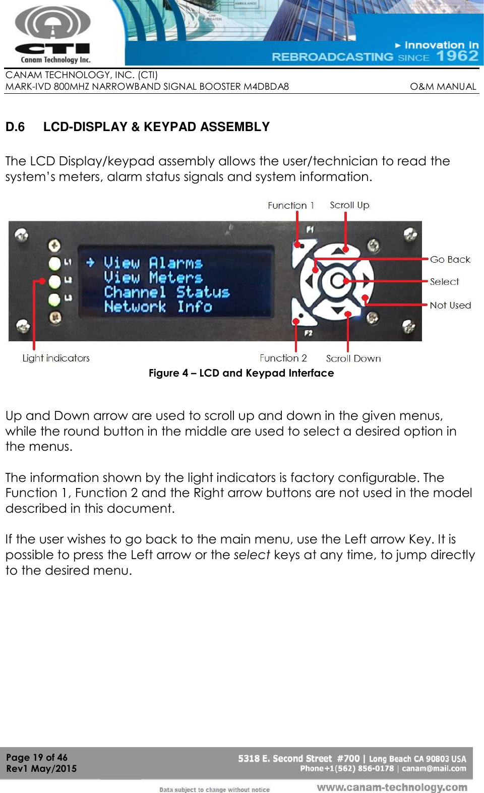
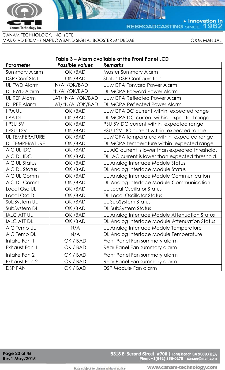
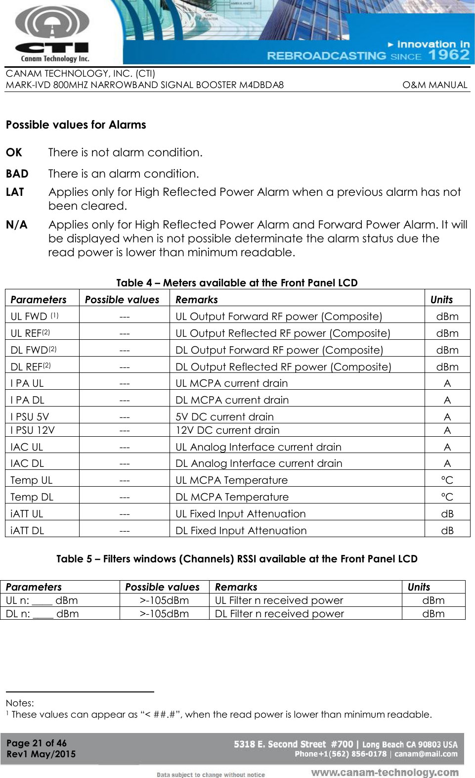
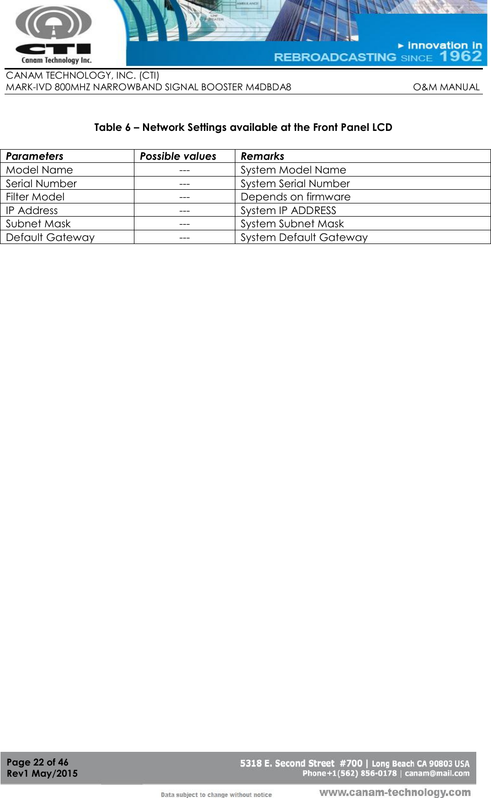
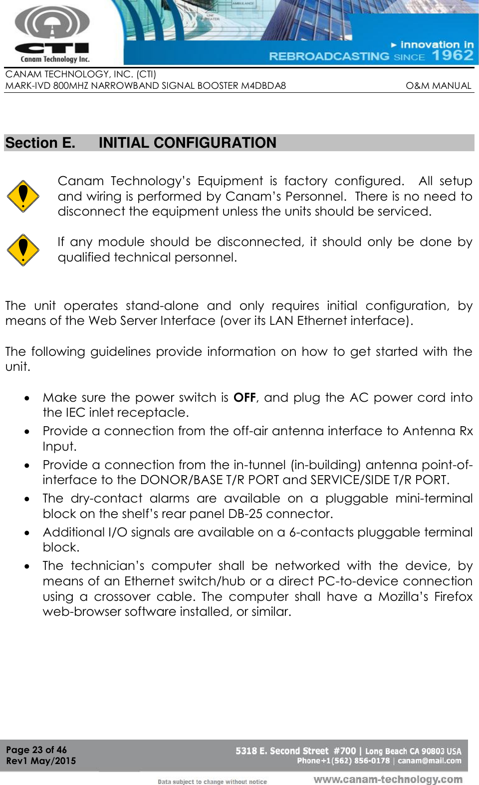
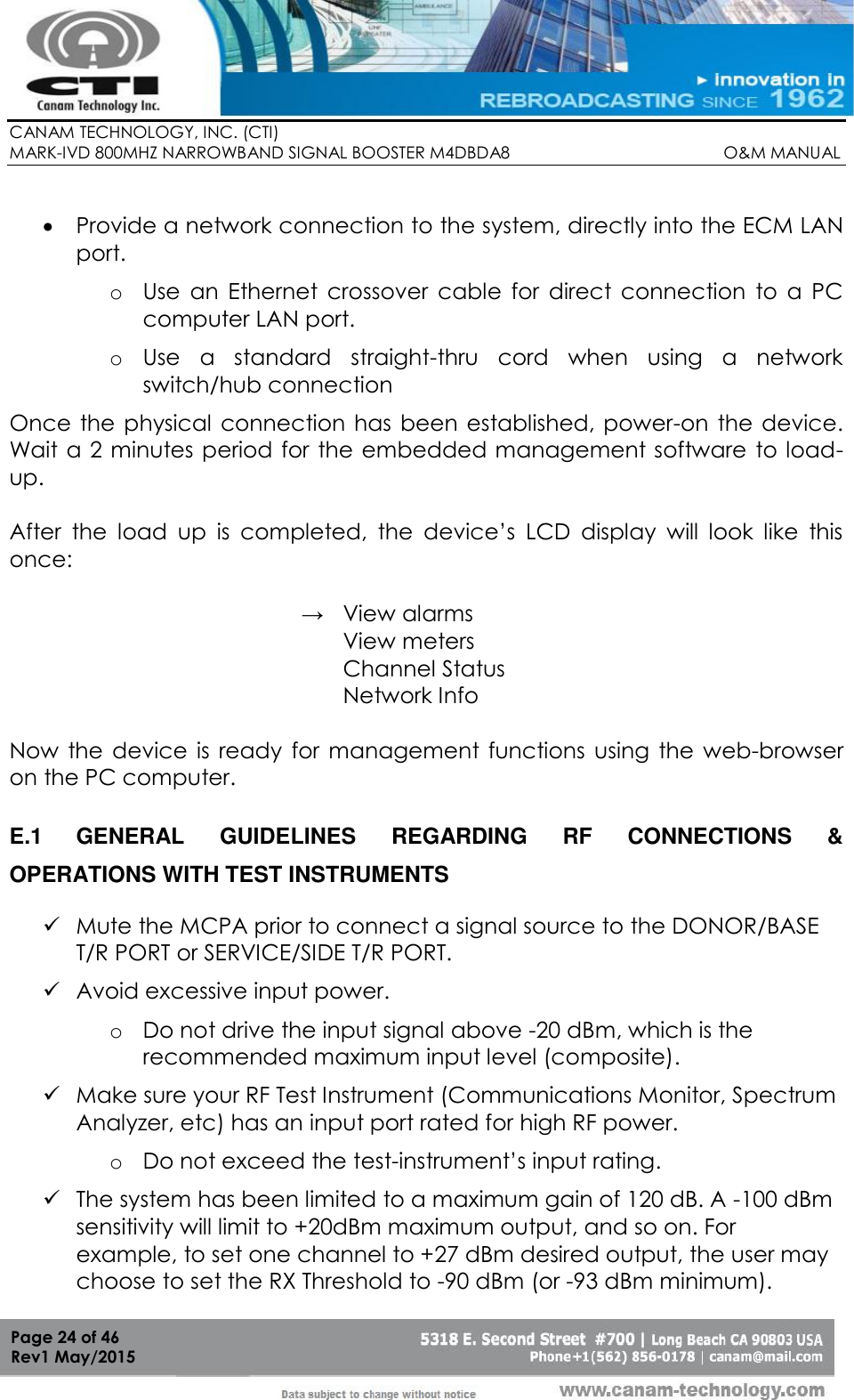
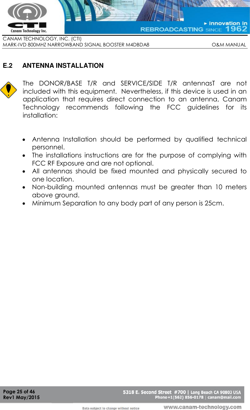
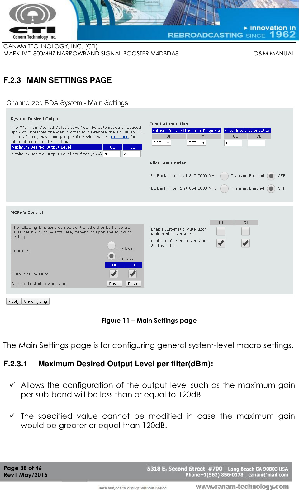
Operation and Maintenance Manual Rev