Canam Technology M4DBDA8 MARK-IV Digital Class-A Signal Booster User Manual UHF CHANNELIZED OUTPUT LIMIT CONTROL
Canam Technology, Inc MARK-IV Digital Class-A Signal Booster UHF CHANNELIZED OUTPUT LIMIT CONTROL
Contents
- 1. Operation and Maintenance Manual Rev
- 2. User Manual Rev
Operation and Maintenance Manual Rev

MARK-IVD 800MHz NARROWBAND SIGNAL BOOSTER
M4DBDA8
OPERATIONS & MAINTENANCE (O&M) MANUAL
REVISION 1
SUBMITTED BY:
CANAM TECHNOLOGY, INC.
May, 2015
CANAM TECHNOLOGY, INC. (CTI)
MARK-IVD 800MHZ NARROWBAND SIGNAL BOOSTER M4DBDA8 O&M MANUAL
Page 2 of 46
Rev1 May/2015
Part 90 Signal Boosters THIS IS A 90.219 CLASS A DEVICE
WARNING. This is NOT a CONSUMER device. It is designed for installation by
FCC LICENSEES and QUALIFIED INSTALLERS. You MUST have an FCC LICENSE
or express consent of an FCC Licensee to operate this device. You MUST
register Class A signal boosters (as defined in 47 CFR 90.219) online
at www.fcc.gov/signal-boosters/registration. Unauthorized use may result in
significant forfeiture penalties, including penalties in excess of $100,000 for
each continuing violation.”

CANAM TECHNOLOGY, INC. (CTI)
MARK-IVD 800MHZ NARROWBAND SIGNAL BOOSTER M4DBDA8 O&M MANUAL
Page 3 of 46
Rev1 May/2015
TABLE OF CONTENTS
Section A. INTRODUCTION ..................................................................................... 6
Section B. GLOSSARY ............................................................................................. 8
Section C. SAFETY PRECAUTIONS .......................................................................... 9
C.1 EQUIPMENT HANDLING AND INSTALLATION ............................................... 9
C.2 POWER SUPPLIES ............................................................................................. 9
C.3 MCPA MODULES ............................................................................................ 9
C.4 RF EXPOSURE ................................................................................................... 9
C.5 MOVING PARTS ............................................................................................ 10
Section D. THEORY OF OPERATION .................................................................... 11
D.1 DESCRIPTION ................................................................................................. 11
D.2 FUNCTIONAL BLOCK DIAGRAM ................................................................. 12
D.3 FEATURES ........................................................................................................ 13
D.4 SPECIFICATIONS ............................................................................................ 14
D.5 FRONT AND REAR PANEL PORTS AND INTERFACES.................................. 17
D.6 LCD-DISPLAY & KEYPAD ASSEMBLY ........................................................... 19
Section E. INITIAL CONFIGURATION ................................................................... 23
E.1 GENERAL GUIDELINES REGARDING RF CONNECTIONS & OPERATIONS
WITH TEST INSTRUMENTS ......................................................................................... 24
E.2 ANTENNA INSTALLATION .............................................................................. 25
Section F. WEB-SERVER GRAPHICAL USER INTERFACE .................................... 26
F.1 FIRST-TIME START CONFIGURATION ............................................................ 26
F.1.1 CONNECTING SYSTEM DIRECTLY TO PC COMPUTER ........................... 26
F.1.2 CONNECTING SYSTEM TO LOCAL AREA NETWORK ............................. 29
F.2 WEB SERVER OPERATIONS ........................................................................... 31
F.2.1 MAIN STATUS PAGE ................................................................................... 32
F.2.2 FILTER STATUS PAGE .................................................................................. 37
F.2.3 MAIN SETTINGS PAGE ............................................................................... 38
F.2.3.1 Maximum Desired Output Level per filter(dBm): .............................. 38
F.2.3.2 Input Attenuation Control .................................................................... 39
F.2.3.3 Pilot test carrier ...................................................................................... 40
F.2.3.4 MCPA Control: ....................................................................................... 40
F.2.3.5 Updating operational settings ............................................................ 41
F.2.4 FILTER SETTINGS PAGE ............................................................................... 42

CANAM TECHNOLOGY, INC. (CTI)
MARK-IVD 800MHZ NARROWBAND SIGNAL BOOSTER M4DBDA8 O&M MANUAL
Page 4 of 46
Rev1 May/2015
TABLES
Table 1 – Front Panel details ................................................................................................................... 17
Table 2 – Rear Panel details. .................................................................................................................. 18
Table 3 – Alarm available at the Front Panel LCD ............................................................................. 20
Table 4 – Meters available at the Front Panel LCD............................................................................ 21
Table 5 – Filters windows (Channels) RSSI available at the Front Panel LCD ................................ 21
Table 6 – Network Settings available at the Front Panel LCD.......................................................... 22
Table 7 – CTCSS Tone frequency codes. ............................................................................................. 44

CANAM TECHNOLOGY, INC. (CTI)
MARK-IVD 800MHZ NARROWBAND SIGNAL BOOSTER M4DBDA8 O&M MANUAL
Page 5 of 46
Rev1 May/2015
TABLE OF FIGURES
Figure 1 – M4DBDA8 General Block Diagram ..................................................................................... 12
Figure 2 - Front Panel details .................................................................................................................. 17
Figure 3 - Rear Panel details. .................................................................................................................. 18
Figure 4 – LCD and Keypad Interface .................................................................................................. 19
Figure 5 – System connected directly to PC computer. ................................................................... 26
Figure 6 – Local Area Connection Status. ........................................................................................... 27
Figure 7 – Local Area Connection Properties. .................................................................................... 28
Figure 8 – System connected into local area network. .................................................................... 29
Figure 9 – Main Status page ................................................................................................................... 32
Figure 10 – Filter Status page .................................................................................................................. 37
Figure 11 – Main Settings page .............................................................................................................. 38
Figure 12 – Value is not into valid range error message ................................................................... 41
Figure 13 – Filter Settings page (1/2) ..................................................................................................... 42
Figure 14 – Filter Settings page (2/2) ..................................................................................................... 43
CANAM TECHNOLOGY, INC. (CTI)
MARK-IVD 800MHZ NARROWBAND SIGNAL BOOSTER M4DBDA8 O&M MANUAL
Page 6 of 46
Rev1 May/2015
Section A. INTRODUCTION
The MARK-IVD 800MHz Narrowband Signal Booster (M4DBDA8) is a Class “A”
Industrial Signal Booster for FCC Part90 PLMRS Public Safety Agencies used to
operate within range 806-817 MHz (UL path), 851-862 MHz (DL path) for Land
Mobile Radio.
This document is the M4DBDA8 Operations and Maintenance Manual,
intended for the Radio Technical Personnel.
This manual is intended to be used with the M4DBDA8 Equipment only. It is
not to be used with any other equipment unless it is authorized by Canam
Technology, Inc.
Canam Technology, Inc provide this document “as is” without any
warranty of any kind. Canam Technology may make changes to the
equipment, software or specifications in this document at any time
without notice to the user. These changes will be notified to the
party responsible for FCC compliance and they will be incorporated
in future releases of this document.
Changes or modifications not expressly approved by the party
responsible for compliance could void the user's authority to
operate the equipment.
This document may contain typographical errors and technical
inaccuracies. Canam Technology will not accept any liability from
the use and misuse of this manual, the information contained within,
or the consequences of any actions resulting from the use of this
information.
CANAM TECHNOLOGY, INC. (CTI)
MARK-IVD 800MHZ NARROWBAND SIGNAL BOOSTER M4DBDA8 O&M MANUAL
Page 7 of 46
Rev1 May/2015
Signal boosters such as the M4DBDA8 generate radio signals and,
therefore, electromagnetic fields. The technical personnel should
have a complete understanding of FCC CFR Title 47 sections 1.1307
and 1.1310. Recommendations are included in this Manual, but
they do not substitute the FCC guidelines.
M4DBDA8 Key Features:
Narrowband Class A Signal Booster, per FCC Part 90.
Maximum Output Power at the antenna port +37 dBm per
carrier.
AGC circuit provides a constant output power, regardless of
the input power.
This device may require the use of antennas for proper functioning,
depending on the application. The installation of the antennas
should be performed by qualified technical personnel. All antennas
should be fixed mounted and physically secured to one location
The people must be away from the antennas at least 1.0 meters to
comply with the RF Human Maximum Permissible Exposure limits, as
long as the antenna system gain is lower than 11.3 dBi. If greater
gain is used the separation should be increased, please refer to the
FCC Rules.
If service should be performed on the antenna, please shut down
the transmitter or lower its power in order to comply with the
maximum permissible exposure.

CANAM TECHNOLOGY, INC. (CTI)
MARK-IVD 800MHZ NARROWBAND SIGNAL BOOSTER M4DBDA8 O&M MANUAL
Page 8 of 46
Rev1 May/2015
Section B. GLOSSARY
AC: Alternate Current.
AGC: Automatic Gain Control, typically used on narrowband channel
filters.
DL: Downlink. Transmission link from the base station to the mobile
station.
DSP: Digital Signal Processing/Processor
ECM: Embedded Control Module (also named as M4-ECM)
GUI: Graphical User Interface
iALC: Input Automatic Level Control (Input broadband limiter).
MCPA: Multi-Carrier High-Power Amplifier
PSU: Power Supply Unit
Relay: Electromechanical switch. The system uses Form-C (SPDT) relays
for external alarms
o COM: Common contact or port
o NC: Normally-Closed contact or port
o NO: Normally-Open contact or port
RF: Radio Frequency
Rx: Receiver
SNMP: Simple Network Management Protocol.
Tx: Transmitter
UL: Uplink. Transmission link from the mobile station to the base station.
CANAM TECHNOLOGY, INC. (CTI)
MARK-IVD 800MHZ NARROWBAND SIGNAL BOOSTER M4DBDA8 O&M MANUAL
Page 9 of 46
Rev1 May/2015
Section C. SAFETY PRECAUTIONS
Ensure that All Operating and Maintenance Personnel do follow INDUSTRY
standard Safety Methods and Precautions. There are system-specific
precautions that must be enforced, such as:
Site Safety Policies
Equipment Handling and Installation
AC power feeds and Power Supply Converters
Multi-Carrier (High) Power Amplifier (MCPA) modules hot surfaces
RF Exposure
C.1 EQUIPMENT HANDLING AND INSTALLATION
1. The enclosure has a weight of 30 kg approximately.
C.2 POWER SUPPLIES
1. When servicing the internal Power Supply and wiring unit, be aware
that power lines are in screw terminal blocks.
2. CAUTION: Removal and Installation requires that the main power
switch be in the OFF position, and the power cord be disconnected
from the enclosure.
C.3 MCPA MODULES
1. Internal MCPA modules are mounted to their corresponding heat
sinks and are used to dissipate DC power. Both the Heat Sink and the
MCPA module MAY be hot.
C.4 RF EXPOSURE
The RF Field Strengths that an individual will be exposed to while doing
maintenance is well below the limits set forth by the FCC & State Laws.
CANAM TECHNOLOGY, INC. (CTI)
MARK-IVD 800MHZ NARROWBAND SIGNAL BOOSTER M4DBDA8 O&M MANUAL
Page 10 of 46
Rev1 May/2015
Nevertheless, there are Safety Precautions that should be adhered when
performing any RF Tests:
1. Never Operate a Transmitter, or Booster Amplifier without adequate
Load/Termination on the Output Port.
2. Ensure all Connections are tight and secured.
3. Ensure all Coaxial Cable Insulation covers the Outer Shield of the
cable.
4. Do Not Touch Exposed System Ports or Coaxial Cable if system is
Transmitting.
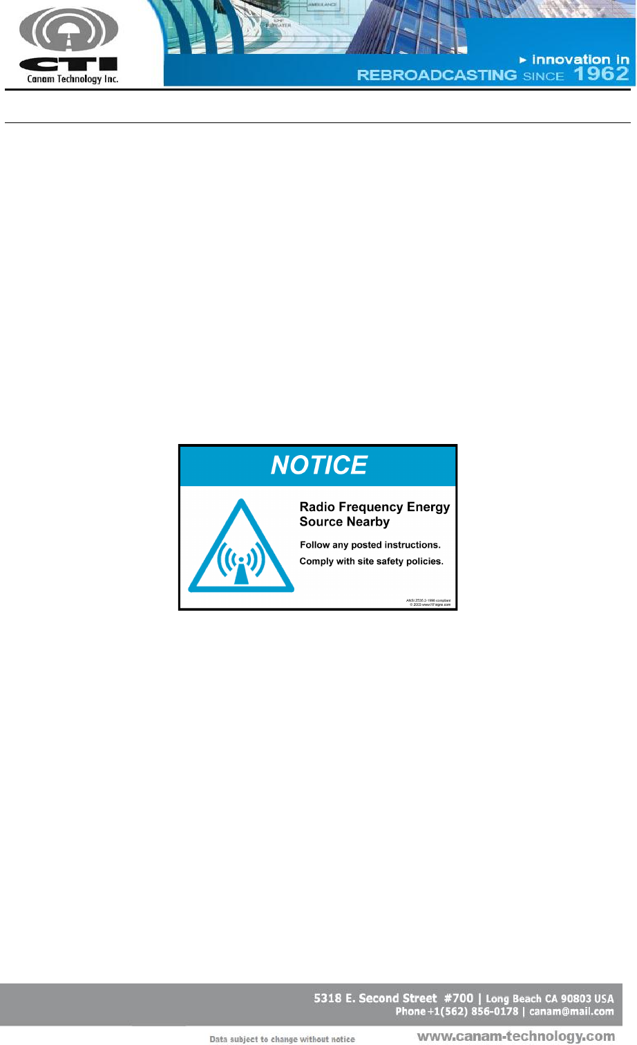
38
RF Signs
Sign Examples
C.5 MOVING PARTS
1. The system has moving parts as fans.
2. Keep your hands and tools away from moving parts.
3. When servicing and wiring unit, be aware main power switch be in
the OFF position and all moving parts are stopped.

CANAM TECHNOLOGY, INC. (CTI)
MARK-IVD 800MHZ NARROWBAND SIGNAL BOOSTER M4DBDA8 O&M MANUAL
Page 11 of 46
Rev1 May/2015
Section D. THEORY OF OPERATION
D.1 DESCRIPTION
The M4DBDA8 is a stand-alone bi-directional & multi-channel Signal
Conditioner that performs on-channel processing (narrowband filtering,
automatic gain control and output level control) on the received signals and
provides a composite equalized multi-channel signal suitable to drive its
internal high-power amplifiers that feed the RF Tx Output signals.
The core Digital Signals Processor (DSP) board uses state-of-art reconfigurable
logic to perform digital signal processing (channelization) thanks to its high-
speed parallel hardware, high speed/performance Analog-to-Digital
Converters (ADCs) and Digital-to-Analog Converters (DACs) to interface with
the analog (Radio Frequency) world. Advanced digital filtering techniques
deliver low group delay and excellent phase linearity to support current
analog transmissions as well as new digital encoding systems.
High-linearity/low-noise analog interface hardware provides pass-band
filtering and gain stages to perform proper signal conditioning to interface
with the DSP digital core sub-system.
Discrete Digital I/O alarms are available for external monitoring.
A built-in Web Server provides a Graphical User Interface (GUI) to ease in
remote monitoring & control. Access is obtained via a PC’s Web Browser
and a TCP/IP connection to the Unit.
CANAM TECHNOLOGY, INC. (CTI)
MARK-IVD 800MHZ NARROWBAND SIGNAL BOOSTER M4DBDA8 O&M MANUAL
Page 12 of 46
Rev1 May/2015
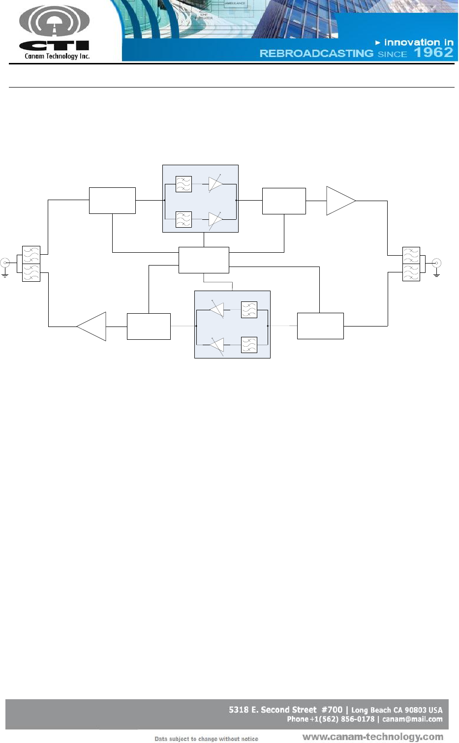
D.2 FUNCTIONAL BLOCK DIAGRAM
.
.
.
AGC
AGC
Narrowband Filters Bank
with AGC per filter
Front-end
Down Converter
RF IF
70MHz IF
70MHz
LO = 833 ~ 845 MHz
REF = 10MHz
Clk
25MHz
Clk
64MHz
Clk
225MHz
MCPA
Back-end
Up Converter
LO = 833 ~ 845 MHz
REF = 10MHz
Clk
25MHz
Micro-Controller
DONOR
(BASE-SIDE)
DUPLEXER
High Freq.
793-805 MHz
Low Freq.
763-775 MHz
SERVICE
(MOBILE-SIDE)
DUPLEXER
.
.
.
AGC
AGC
Narrowband Filters Bank
with AGC per filter
Front-end
Down Converter RF
IF
70MHz
IF
70MHz
LO = 863 ~ 875 MHz
REF = 10MHz
Clk
25MHz
Clk
225MHz
MCPA
Back-end
Up Converter
LO = 863 ~ 875 MHz
REF = 10MHz
Clk
25MHz
High Freq.
793-805 MHz
Low Freq.
763-775 MHz
Figure 1 – M4DBDA8 General Block Diagram

CANAM TECHNOLOGY, INC. (CTI)
MARK-IVD 800MHZ NARROWBAND SIGNAL BOOSTER M4DBDA8 O&M MANUAL
Page 13 of 46
Rev1 May/2015
D.3 FEATURES
800MHz Digital Channelized Bidirectional Amplifier system.
State-of-the-art Multi-channel digital processing system for on-frequency
repeater applications (coverage extension, in-tunnel/in-building, etc).
Preserves the frequency stability, audio fidelity and data content of the
original over-the-air signal with minimum degradation
120 dB Gain per filter-window, maximum
Individual Automatic Gain Control (AGC) per filter ensures effective
recuperation of weak signals from far-end or worst case situations users,
despite other strong simultaneous signals on-scene. AGC delivers
constant output power level per channel regardless of their input level
variations.
High Input Sensitivity (<= -110 dBm) with programmable Individual Rx
Threshold level (Squelch) per filter-window.
Software-Defined Radio System architecture.
Fully software programmable channel frequencies, monitoring and
control settings & status indicators.
High-linearity/ low-noise analog processing blocks.
Embedded microcontroller for control and self-monitoring functions.
Remote control via web-server.
Discrete Digital I/O alarm signals available,
o Opto-coupler inputs and relay contact outputs
AC powered
CANAM TECHNOLOGY, INC. (CTI)
MARK-IVD 800MHZ NARROWBAND SIGNAL BOOSTER M4DBDA8 O&M MANUAL
Page 14 of 46
Rev1 May/2015
D.4 SPECIFICATIONS
Parameter
Specification
Frequency range: Customs windows can be
accommodated within the uplink/downlink sub-
bands
Contact Canam with your specific frequency plan
806-817 MHz / 851-862 MHz overall range
The system bandwidth per path (UL & DL) may
be specified as 3, 7, 10, 15 or 18 MHz
USA post re-banding: 806-817/851-862 MHz
Minimum Sensitivity for greater than 20 dB output
SINAD (DAQ 3.4)
(excluding custom-built pre-selector cavity filters)
-110 dBm @ SINAD >= 20
-115 dBm @ SINAD >= 12 dB
Narrowband filters Selectivity – Adjacent Channel
Rejection (ACR)
20-70 dB, per filter mask (programmable)
Absolute Group Delay
10-110 usec, per filter mask (programmable)
Example of model “30 Di” filter mask :
BW = 64 kHz @ -3dB passband typ.
ACR ≥ 70dB @ +/- 75 kHz
Group delay ≤ 30 usec (typ.)
Channel bandwidth
25kHz
Filter center frequency spacing
6.25kHz, 12.5kHz or 25kHz steps
Narrowband small-signal gain per filter window
120 dB max.
Narrowband Automatic Gain Control (AGC) range
on a per-filter window basis
50 dB typ.
Maximum input power (composite) for no-damage
-20 dBm (typ.), or subject to custom factory
build option
Input (Rx) IM Rejection, per TIA standard
>60 dB
Narrowband Constant Output level regardless of
input level variations, per filter
+/- 1 dB typ
Broadband input Automatic Level Control (iALC)
range to prevent Rx/front-end undesired saturation
0-30 dB, 1 dB digital step (automatic)
Analog FM Modulation Distortion & Digital
Modulations B.E.R.
3%
Noise Figure (without custom front-end filtering or
padding)
7 dB typical
Broadband output level adjustment range
1-30 dB typ. 1dB digital step
Output MCPA IMD at +25 dBm per channel, all
channels transmitting
≥ 60 dBc typ.
Output Multi-Carrier Power Amplifier P1dB
≥ +47 dBm (50Watt)
Spurious & harmonics outputs
<-36 dBm (EU), <-13 dBm (US Narrow)
Input & Output RF ports (typ)
50 Ohm, Type-N (female), 1.5:1 VSWR
CANAM TECHNOLOGY, INC. (CTI)
MARK-IVD 800MHZ NARROWBAND SIGNAL BOOSTER M4DBDA8 O&M MANUAL
Page 15 of 46
Rev1 May/2015
Parameter
Specification
MAJOR SOFTWARE DEFINED FIELD-PROGRAMMABLE SETTINGS
Narrowband Filters selectivity and bandwidth
(firmware system personality)
Filters central frequencies (Fo) in 3.125 KHz steps
Input (Rx) Threshold level, per narrowband window/filter
Output Power level, per channel or overall
Receive Signal Strength Indicator level – RSSI, per window
Number of filters per path (depending on selected
firmware mask)
10 or 20
CTCSS PL Tone detection (programmable)
OTHER
4RU or 6RU Rackmount enclosures (total rack space
depends on custom filtering requirements per actual
user frequency plan)
NEMA-1
Wallmount enclosure (NEMA 12/4/4X)
Available upon request
Duty Cycle
100 %
Operating ambient temperature range
-30 to +60° Celsius standard
MBTF
> 50,000 hours (RF only)
> 40,000 h (fiber-fed)
Power requirements @ full load
(actual power draw depends on actual system
configuration)
300 Watt max @ 100-240 Vac, 50/60 Hz
28 VDC input OPTIONAL
FIBER OPTICS (optional)
Frequency Range
10 – 1000 MHz
Gain Flatness
±1 dB
Input Third Order Intercept
+13dBm
Noise Figure / Noise Floor
23dB / -110dBm @ 10kHz BW
Laser Type
DBF / 1310nm ± 20nm (CWDM available)
Parameter
Specification
INTERFACES, REMOTE CONTROL AND MONITORING
Non-Intrusive (tap) coax RF ports
Type-N (female), 50 Ohm
Network remote control (Ethernet 10/100)
TCP/IP: web server, SNMP
PC Software
Any generic web-browser
Local Debug Port
Serial RS-232
CANAM TECHNOLOGY, INC. (CTI)
MARK-IVD 800MHZ NARROWBAND SIGNAL BOOSTER M4DBDA8 O&M MANUAL
Page 16 of 46
Rev1 May/2015
Local Human-Machine-Interface
LCD display with 7-button keypad, plus LED
Indicators
Factory-Programmable-function Discrete Digital I/O
(Dry contact, voltage-free)
4 Relay output contacts
4 Opto-isolated inputs
Internal Sensors, overall system
Temperature, DC Voltage/Current,
Locked-rotor cooling fan monitoring,
Output RF Forward & Reverse,
Input RF Composite Power (DL and UL)
True-RMS RF Detectors/Limiters (In/Out)
CUSTOM BUILD OPTIONS
Duplexer/Multiplexer filters for common Tx/Rx antenna, or separate DL and UL paths (custom build)
Low noise RF-over-Fiber-Optic transceiver
Multi Carrier Power Amplifiers (MCPA) are optional per system requirements
CTCSS Analog PL Tone Detection
NFPA72-2010 compliant or Custom Input/Output status/monitoring functionality, for example: Open
door, Low-Battery, AC Power Failure, Smoke detector, Strobe light or Siren indicator, etc.
Sensors DC Voltage Buffered Outputs 0-5V for external SCADA monitoring: MCPA DC Voltage/Current,
Composite RF Output power, Temperature, RF output, ALC monitor, or others upon custom demand.
Frequency (shift) in-band translator
CANAM TECHNOLOGY, INC. (CTI)
MARK-IVD 800MHZ NARROWBAND SIGNAL BOOSTER M4DBDA8 O&M MANUAL
Page 17 of 46
Rev1 May/2015
D.5 FRONT AND REAR PANEL PORTS AND INTERFACES
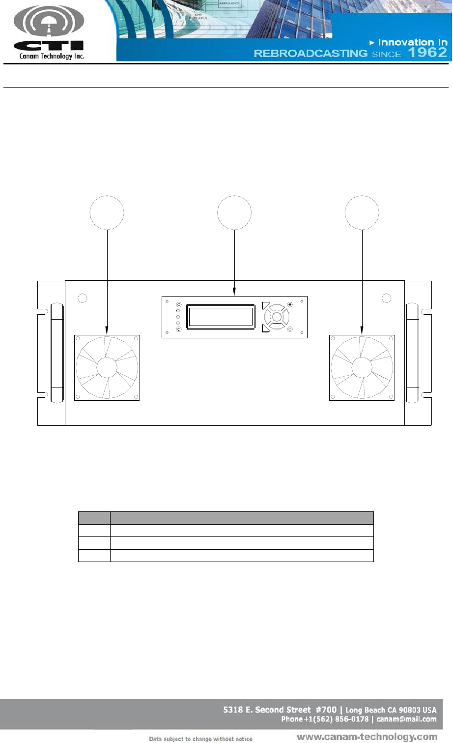
Figure 2 shows the system front panel. A brief explanation is given in Table 1.
13
2
Figure 2 - Front Panel details
Table 1 – Front Panel details
Item
Description
1
Intake fan 1
2
LCD Display/Keypad
3
Intake fan 2
CANAM TECHNOLOGY, INC. (CTI)
MARK-IVD 800MHZ NARROWBAND SIGNAL BOOSTER M4DBDA8 O&M MANUAL
Page 18 of 46
Rev1 May/2015
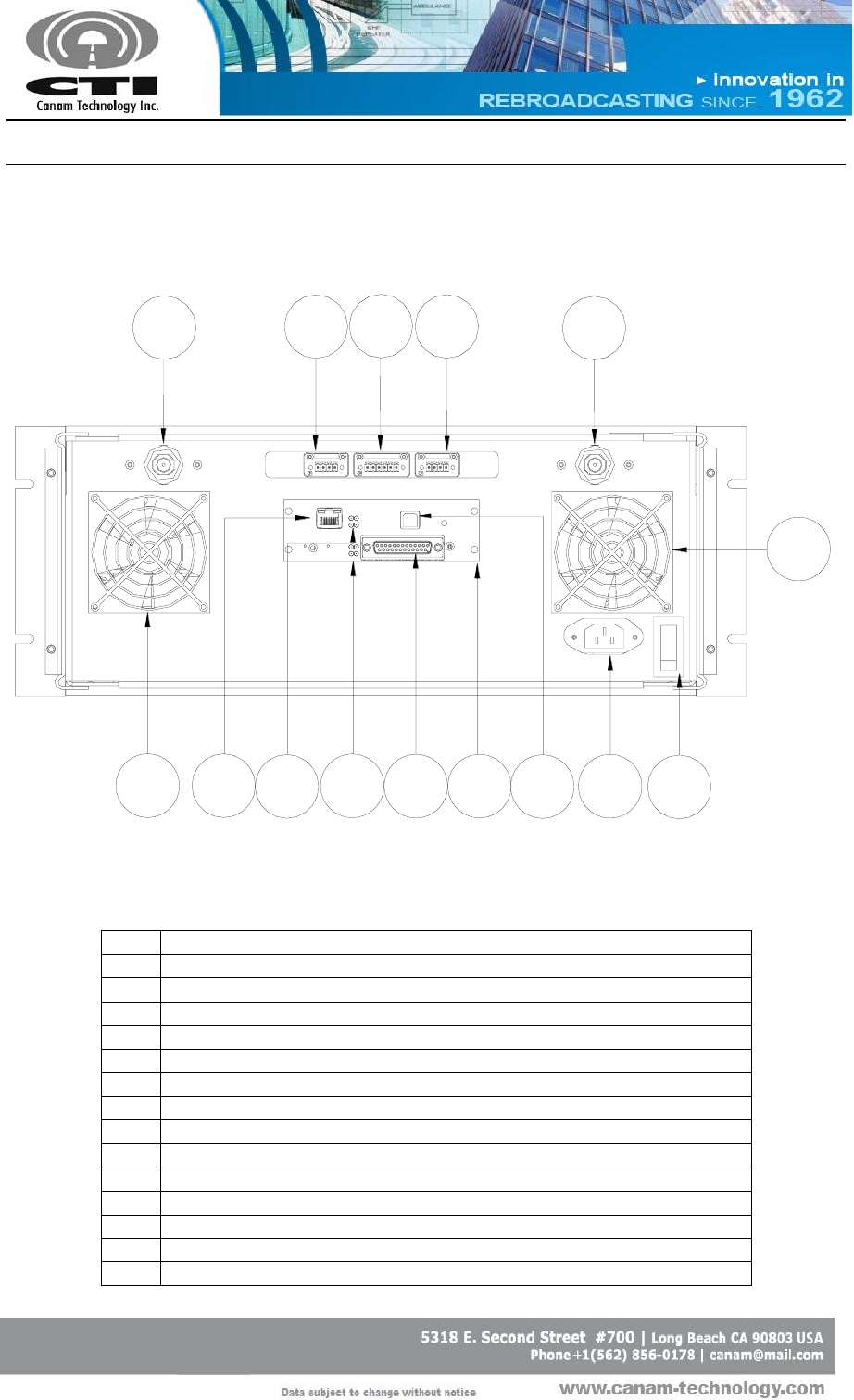
Figure 3 shows the system rear panel. A brief explanation of each connector
is given in Table 2.
15
3
24
7
6810911 12 13
14
14
Figure 3 - Rear Panel details.
Table 2 – Rear Panel details.
Item
Description
1
DONOR/BASE T/R PORT
2
FAN 1 DE-01
3
AUX I/O DE-02
4
FAN 1 DE-03
5
SERVICE/SIDE T/R PORT
6
(ECM) ETHERNET 10/100 NETWORK PORT
7
(ECM) GREEN LEDS STATUS INDICATORS
8
(ECM) RED LEDS (RELAY CONTACTS)
9
(ECM) DB-25 I/O CONNECTOR
10
PLUGGABLE EMBEDDED CONTROL MODULE (ECM)
11
(ECM) FACTORY USB DEBUG PORT
12
AC POWER "IEC" INLET
13
AC MAINS ON/OFF POWER SWITCH
14
AIR EXHAUST REAR FANS
CANAM TECHNOLOGY, INC. (CTI)
MARK-IVD 800MHZ NARROWBAND SIGNAL BOOSTER M4DBDA8 O&M MANUAL
Page 19 of 46
Rev1 May/2015
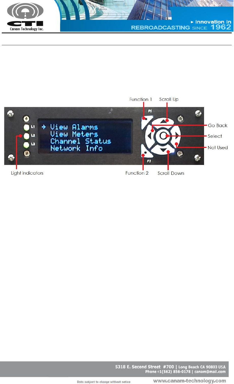
D.6 LCD-DISPLAY & KEYPAD ASSEMBLY
The LCD Display/keypad assembly allows the user/technician to read the
system’s meters, alarm status signals and system information.
Figure 4 – LCD and Keypad Interface
Up and Down arrow are used to scroll up and down in the given menus,
while the round button in the middle are used to select a desired option in
the menus.
The information shown by the light indicators is factory configurable. The
Function 1, Function 2 and the Right arrow buttons are not used in the model
described in this document.
If the user wishes to go back to the main menu, use the Left arrow Key. It is
possible to press the Left arrow or the select keys at any time, to jump directly
to the desired menu.
CANAM TECHNOLOGY, INC. (CTI)
MARK-IVD 800MHZ NARROWBAND SIGNAL BOOSTER M4DBDA8 O&M MANUAL
Page 20 of 46
Rev1 May/2015
Table 3 – Alarm available at the Front Panel LCD
Parameter
Possible values
Remarks
Summary Alarm
OK /BAD
Master Summary Alarm
DSP Conf Stat
OK /BAD
Status DSP Configuration
UL FWD Alarm
“N/A”/OK/BAD
UL MCPA Forward Power Alarm
DL FWD Alarm
“N/A”/OK/BAD
DL MCPA Forward Power Alarm
UL REF Alarm
LAT/“N/A”/OK/BAD
UL MCPA Reflected Power Alarm
DL REF Alarm
LAT/“N/A”/OK/BAD
DL MCPA Reflected Power Alarm
I PA UL
OK /BAD
UL MCPA DC current within expected range
I PA DL
OK /BAD
DL MCPA DC current within expected range
I PSU 5V
OK /BAD
PSU 5V DC current within expected range
I PSU 12V
OK /BAD
PSU 12V DC current within expected range
UL TEMPERATURE
OK /BAD
UL MCPA temperature within expected range
DL TEMPERATURE
OK /BAD
DL MCPA temperature within expected range
AIC UL IDC
OK /BAD
UL AIC current is lower than expected threshold.
AIC DL IDC
OK /BAD
DL IAC current is lower than expected threshold.
AIC UL Status
OK /BAD
UL Analog Interface Module Status
AIC DL Status
OK /BAD
DL Analog Interface Module Status
AIC UL Comm
OK /BAD
UL Analog Interface Module Communication
AIC DL Comm
OK /BAD
DL Analog Interface Module Communication
Local Osc UL
OK /BAD
UL Local Oscillator Status
Local Osc DL
OK /BAD
DL Local Oscillator Status
SubSystem UL
OK /BAD
UL SubSystem Status
SubSystem DL
OK /BAD
DL SubSystem Status
IALC ATT UL
OK /BAD
UL Analog Interface Module Attenuation Status
IALC ATT DL
OK /BAD
DL Analog Interface Module Attenuation Status
AIC Temp UL
N/A
UL Analog Interface Module Temperature
AIC Temp DL
N/A
DL Analog Interface Module Temperature
Intake Fan 1
OK / BAD
Front Panel Fan summary alarm
Exhaust Fan 1
OK / BAD
Rear Panel Fan summary alarm
Intake Fan 2
OK / BAD
Front Panel Fan summary alarm
Exhaust Fan 2
OK / BAD
Rear Panel Fan summary alarm
DSP FAN
OK / BAD
DSP Module Fan alarm
CANAM TECHNOLOGY, INC. (CTI)
MARK-IVD 800MHZ NARROWBAND SIGNAL BOOSTER M4DBDA8 O&M MANUAL
Page 21 of 46
Rev1 May/2015
Possible values for Alarms
OK
There is not alarm condition.
BAD
There is an alarm condition.
LAT
Applies only for High Reflected Power Alarm when a previous alarm has not
been cleared.
N/A
Applies only for High Reflected Power Alarm and Forward Power Alarm. It will
be displayed when is not possible determinate the alarm status due the
read power is lower than minimum readable.
Table 4 – Meters available at the Front Panel LCD
Parameters
Possible values
Remarks
Units
UL FWD (1)
---
UL Output Forward RF power (Composite)
dBm
UL REF(2)
---
UL Output Reflected RF power (Composite)
dBm
DL FWD(2)
---
DL Output Forward RF power (Composite)
dBm
DL REF(2)
---
DL Output Reflected RF power (Composite)
dBm
I PA UL
---
UL MCPA current drain
A
I PA DL
---
DL MCPA current drain
A
I PSU 5V
---
5V DC current drain
A
I PSU 12V
---
12V DC current drain
A
IAC UL
---
UL Analog Interface current drain
A
IAC DL
---
DL Analog Interface current drain
A
Temp UL
---
UL MCPA Temperature
ºC
Temp DL
---
DL MCPA Temperature
ºC
iATT UL
---
UL Fixed Input Attenuation
dB
iATT DL
---
DL Fixed Input Attenuation
dB
Table 5 – Filters windows (Channels) RSSI available at the Front Panel LCD
Parameters
Possible values
Remarks
Units
UL n: ____ dBm
>-105dBm
UL Filter n received power
dBm
DL n: ____ dBm
>-105dBm
DL Filter n received power
dBm
Notes:
1
These values can appear as “< ##.#”, when the read power is lower than minimum readable.
CANAM TECHNOLOGY, INC. (CTI)
MARK-IVD 800MHZ NARROWBAND SIGNAL BOOSTER M4DBDA8 O&M MANUAL
Page 22 of 46
Rev1 May/2015
Table 6 – Network Settings available at the Front Panel LCD
Parameters
Possible values
Remarks
Model Name
---
System Model Name
Serial Number
---
System Serial Number
Filter Model
---
Depends on firmware
IP Address
---
System IP ADDRESS
Subnet Mask
---
System Subnet Mask
Default Gateway
---
System Default Gateway
CANAM TECHNOLOGY, INC. (CTI)
MARK-IVD 800MHZ NARROWBAND SIGNAL BOOSTER M4DBDA8 O&M MANUAL
Page 23 of 46
Rev1 May/2015
Section E. INITIAL CONFIGURATION
Canam Technology’s Equipment is factory configured. All setup
and wiring is performed by Canam’s Personnel. There is no need to
disconnect the equipment unless the units should be serviced.
If any module should be disconnected, it should only be done by
qualified technical personnel.
The unit operates stand-alone and only requires initial configuration, by
means of the Web Server Interface (over its LAN Ethernet interface).
The following guidelines provide information on how to get started with the
unit.
Make sure the power switch is OFF, and plug the AC power cord into
the IEC inlet receptacle.
Provide a connection from the off-air antenna interface to Antenna Rx
Input.
Provide a connection from the in-tunnel (in-building) antenna point-of-
interface to the DONOR/BASE T/R PORT and SERVICE/SIDE T/R PORT.
The dry-contact alarms are available on a pluggable mini-terminal
block on the shelf’s rear panel DB-25 connector.
Additional I/O signals are available on a 6-contacts pluggable terminal
block.
The technician’s computer shall be networked with the device, by
means of an Ethernet switch/hub or a direct PC-to-device connection
using a crossover cable. The computer shall have a Mozilla’s Firefox
web-browser software installed, or similar.

CANAM TECHNOLOGY, INC. (CTI)
MARK-IVD 800MHZ NARROWBAND SIGNAL BOOSTER M4DBDA8 O&M MANUAL
Page 24 of 46
Rev1 May/2015
Provide a network connection to the system, directly into the ECM LAN
port.
o Use an Ethernet crossover cable for direct connection to a PC
computer LAN port.
o Use a standard straight-thru cord when using a network
switch/hub connection
Once the physical connection has been established, power-on the device.
Wait a 2 minutes period for the embedded management software to load-
up.
After the load up is completed, the device’s LCD display will look like this
once:
→ View alarms
View meters
Channel Status
Network Info
Now the device is ready for management functions using the web-browser
on the PC computer.
E.1 GENERAL GUIDELINES REGARDING RF CONNECTIONS &
OPERATIONS WITH TEST INSTRUMENTS
Mute the MCPA prior to connect a signal source to the DONOR/BASE
T/R PORT or SERVICE/SIDE T/R PORT.
Avoid excessive input power.
o Do not drive the input signal above -20 dBm, which is the
recommended maximum input level (composite).
Make sure your RF Test Instrument (Communications Monitor, Spectrum
Analyzer, etc) has an input port rated for high RF power.
o Do not exceed the test-instrument’s input rating.
The system has been limited to a maximum gain of 120 dB. A -100 dBm
sensitivity will limit to +20dBm maximum output, and so on. For
example, to set one channel to +27 dBm desired output, the user may
choose to set the RX Threshold to -90 dBm (or -93 dBm minimum).
CANAM TECHNOLOGY, INC. (CTI)
MARK-IVD 800MHZ NARROWBAND SIGNAL BOOSTER M4DBDA8 O&M MANUAL
Page 25 of 46
Rev1 May/2015
E.2 ANTENNA INSTALLATION
The DONOR/BASE T/R and SERVICE/SIDE T/R antennasT are not
included with this equipment. Nevertheless, if this device is used in an
application that requires direct connection to an antenna, Canam
Technology recommends following the FCC guidelines for its
installation:
Antenna Installation should be performed by qualified technical
personnel.
The installations instructions are for the purpose of complying with
FCC RF Exposure and are not optional.
All antennas should be fixed mounted and physically secured to
one location.
Non-building mounted antennas must be greater than 10 meters
above ground.
Minimum Separation to any body part of any person is 25cm.
CANAM TECHNOLOGY, INC. (CTI)
MARK-IVD 800MHZ NARROWBAND SIGNAL BOOSTER M4DBDA8 O&M MANUAL
Page 26 of 46
Rev1 May/2015
Section F. WEB-SERVER GRAPHICAL USER INTERFACE
F.1 FIRST-TIME START CONFIGURATION
The system can be connected directly to PC computer using an Ethernet
crossover cable or to LAN using a standard straight-thru cord when using a
network switch/hub connection.
Section F.1.1 shows how to interface a computer directly to the system using
a cross-over cable in case there is no network switch available.
Section F.1.2 shows how to interface the computer to the RF device by
means of a network Ethernet switch.
Before to access system built-in Web Server verify your web browser is
working with java script enabled.
These are some web links showing HOW-TO enable java script.
https://support.microsoft.com/en-us/gp/howtoscript
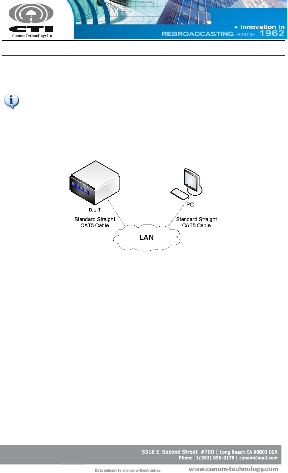
F.1.1 CONNECTING SYSTEM DIRECTLY TO PC COMPUTER
Use an Ethernet crossover CAT5 cable for direct connection to a PC
computer LAN port.
Figure 5 – System connected directly to PC computer.
Connect the system to PC computer directly into the ECM LAN port.
The equipment IP address (192.168.100.75) and Network Mask
(255.255.255.0) are shown in the LCD display.
CANAM TECHNOLOGY, INC. (CTI)
MARK-IVD 800MHZ NARROWBAND SIGNAL BOOSTER M4DBDA8 O&M MANUAL
Page 27 of 46
Rev1 May/2015
o To verify IP address press the Down key in LCD Display and
Keypad assembly until get IP ADDRESS and SUBNET MASK values.
Configure the local computer IP address and Network Mask to allow
access to the controller, within the same sub-net.
Windows 7
1. Go to “Start >> Control Panel >>Network and Internet”.
2. Left-click on “View network status and tasks”.
3. In “Network and Sharing Center”, right click on “Local Area
Connection” and go to “Properties”.
Figure 6 – Local Area Connection Status.
CANAM TECHNOLOGY, INC. (CTI)
MARK-IVD 800MHZ NARROWBAND SIGNAL BOOSTER M4DBDA8 O&M MANUAL
Page 28 of 46
Rev1 May/2015
4. Look for “Internet Protocol Version 4 (TCP/IPv4)” and click
“Properties”.
Figure 7 – Local Area Connection Properties.
5. Follows steps 4 and 5 as for Windows XP.
Open a web browser and access the equipment by typing, in the
address bar, the IP address of the equipment (ex.: http://192.168.100.75).
o Login with username = operator, password = operator.
CANAM TECHNOLOGY, INC. (CTI)
MARK-IVD 800MHZ NARROWBAND SIGNAL BOOSTER M4DBDA8 O&M MANUAL
Page 29 of 46
Rev1 May/2015
F.1.2 CONNECTING SYSTEM TO LOCAL AREA NETWORK
Use standard straight-thru cable for network switch/hub connection.
To connect system to LAN, it is necessary to know the subnet the PC
computer is currently plugged into.
If no network is available the user shall remain using the crossover
interconnection
Figure 8 – System connected into local area network.
The following steps are necessary to connect system to LAN:
1. Connect the radio system and the computer together by means of
ethernet switch.
2. The radio system has a default IP address similar to 192.168.100.75 (S.M.
255.255.255.0)
3. Configure the computer’s IP address within the same subnet as the
radio system, 192.168.100.X (for example 192.168.100.75, S.M =
255.255.255.0) as shown in previous section.
4. Open a web browser and access the equipment by typing, in the
address bar, the IP address of the radio equipment
(http://192.168.100.75).
5. Login with username = operator, password = operator

CANAM TECHNOLOGY, INC. (CTI)
MARK-IVD 800MHZ NARROWBAND SIGNAL BOOSTER M4DBDA8 O&M MANUAL
Page 30 of 46
Rev1 May/2015
User may change the radio system’s IP Address to a different subnet setting if
desired.
1. First, it is necessary to connect system directly to PC Computer using
the crossover cable.
2. Open a web browser and access the equipment by typing, in the
address bar, the IP address of the equipment.
o Login with username = technician, password = technician.
3. Go to the “Network Settings” page (see left-side menu) to change the
current settings to be assigned by the network administrator.
o IP Address, Network Mask, Gateway Address.
o The controller requires a fix address; it does not allow DHCP settings.
o Enter or press “Apply” button to apply the new parameters, and
then restart the system.
o Now the system controller can be plugged into the local area
network served by your LAN Switch or Router.

CANAM TECHNOLOGY, INC. (CTI)
MARK-IVD 800MHZ NARROWBAND SIGNAL BOOSTER M4DBDA8 O&M MANUAL
Page 31 of 46
Rev1 May/2015
F.2 WEB SERVER OPERATIONS
The built-in Web Server provides a Graphical User Interface (GUI) to ease in
remote monitoring & control. Some pages shown by the Web Server are the
following:
“Main Status”: depicts status alarm indicators and meters.
“Filter Status”: depicts filter windows status and indicators.
“Main Settings”: is used to configure system-level macro settings.
“Filter Settings” contains the settings that can be configured for each
filter window.
CANAM TECHNOLOGY, INC. (CTI)
MARK-IVD 800MHZ NARROWBAND SIGNAL BOOSTER M4DBDA8 O&M MANUAL
Page 32 of 46
Rev1 May/2015
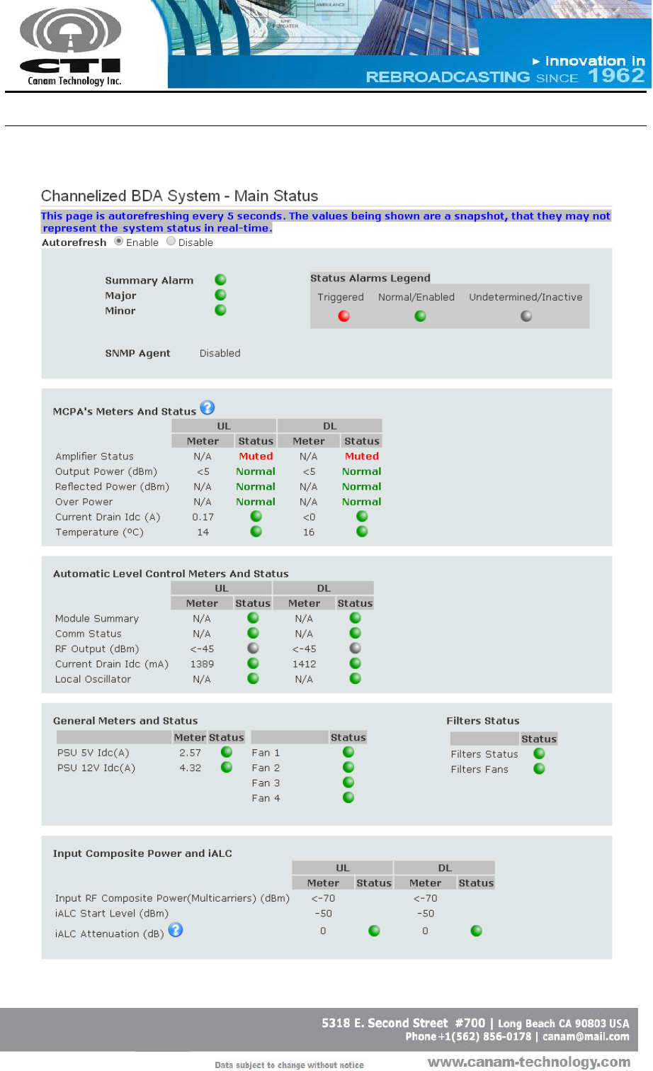
F.2.1 MAIN STATUS PAGE
Figure 9 – Main Status page
CANAM TECHNOLOGY, INC. (CTI)
MARK-IVD 800MHZ NARROWBAND SIGNAL BOOSTER M4DBDA8 O&M MANUAL
Page 33 of 46
Rev1 May/2015
This page shows meters and the different alarms and meters. The auto-refresh
radio-button allows periodic page updates every 5 seconds approximately.
Summary Alarm
Master Summary alarm Indicator. Green if no single
alarm is present in the system, red otherwise.
Major Alarm
Major Alarm indicator. It summarizes the DSP Modules
Status alarms, the RF Output Status alarm and the off-
air Receive Warning alarm. The indicator is Green if all
this alarms are ok, red otherwise.
Minor Alarm
Minor Alarm indicator. It summarizes the alarms that
concern to the Fan status, current consumption and
temperature status. The indicator is Green if all this
alarms are ok, red otherwise.
SNMP Agent
Shows the SNMP Agent current status.
MCPA’s Meters and Status
Amplifier Status
Indicates if the MCPA Output is “Unmuted”,
“Muted” or “Muted by Alarm”(in case the MCPA
Reflected Power Alarm is “Triggered” or
“Latched” and the option “Enable Automatic
Mute upon Reflected Power Alarm” has been
selected in Main Settings page).
Output Power (dBm)
Composite Output Power.
The Status will be “Undetermined” when the power
is not readable; “Normal” when it is above the
threshold and “Triggered” if it is below the
threshold.

CANAM TECHNOLOGY, INC. (CTI)
MARK-IVD 800MHZ NARROWBAND SIGNAL BOOSTER M4DBDA8 O&M MANUAL
Page 34 of 46
Rev1 May/2015
Reflected Power
(dBm)
Composite Reflected Power.
The Status will be “Undetermined” when the power
is not readable; “Normal” when it is below the
threshold; “Triggered” if it is above the threshold
and “Latched” when a previous Reflected Power
Alarm has not been cleared.
Current Drain Idc (A)
MCPA DC current drain.
The Status indicator will be green when the current
is within the operating levels, red otherwise.
Temperature (ºC)
MCPA heat-sink temperature.
The Status indicator will be green when the
temperature is within the operating levels, red
otherwise.
Analog Interface Meters and Status
Modules Summary
Indicator is Green if module is active with no alarms,
red otherwise.
Comm Status
Indicator is Green if Analog Interface Card
communication is working, red otherwise.
RF Output (dBm)
Composite Output Power. This is the multi-carriers
signal coming out of the DSP filtering process, used to
drive the broadband output MCPA.
The Status indicator will be green if the power is
above the threshold, gray otherwise (no traffic).
Current Drain Idc
(mA)
Analog-Module DC Current Drain (mA).
The Status indicator will be green when the current is
above the threshold, red otherwise.
Local Oscillator
Indicator is Green if Local Oscillator is locked, red
otherwise.
CANAM TECHNOLOGY, INC. (CTI)
MARK-IVD 800MHZ NARROWBAND SIGNAL BOOSTER M4DBDA8 O&M MANUAL
Page 35 of 46
Rev1 May/2015
General Meters and Status
PSU 5V Idc (A)/
PSU 12V Idc (A)
5Vdc/12Vdc current meter. Indicator is green if current
is within the operating levels, red otherwise.
Fan 1/ Fan 2
Indicator. Green if front fans are fully operational as
detected by the air flow sensors; red otherwise.
Fan 3/ Fan 4
Indicator. Green if rear fans are fully operational as
detected by the air flow sensors; red otherwise.
Filter Status
Indicator. It will be green if DSP Module firmware or
communication are working as expected; red
otherwise.
In case the alarm is triggered (indicator red), the icon
is displayed in Main Status, Filter Status
UL, Filter Status DL, Filter Settings UL, Filter Settings DL and
Filters Configuration Pages.
Any action related to DSP Filters configuration is
blocked.
In addition, the MCPAs are automatically muted. The
message “Both MCPA have been automatically muted
due to a DSP Module Alarm” is displayed in Main
Settings page.
Filter Fans
Indicator. DSP module fan is fully operational; red
otherwise.
CANAM TECHNOLOGY, INC. (CTI)
MARK-IVD 800MHZ NARROWBAND SIGNAL BOOSTER M4DBDA8 O&M MANUAL
Page 36 of 46
Rev1 May/2015
Input Composite Power and iALC
Input RF Composite
Power (Multicarriers)
(dBm)
Received level (composite) near or within the
limiter range.
For RSSI per filter window above -105dBm please go
to Filters Status page.
iALC Start Level (dBm)
Input Automatic Level Control limiter threshold.
iALC Attenuation (dB)
Input Automatic Level Control attenuator dynamic
value. Valid for CW signals, intended for
maintenance purposes.
The Status indicator will be green when the value is
less than 1; yellow is the value is greater than 1 but
less than 15; red otherwise.
The iALC input Attenuation is automatically set by
the system in order to limit the Input RF Composite
Power at the value indicated as iALC Set Point. If
the Input RF Composite Power is greater than iALC
Start Level it is attenuated to avoid system
saturation.
CANAM TECHNOLOGY, INC. (CTI)
MARK-IVD 800MHZ NARROWBAND SIGNAL BOOSTER M4DBDA8 O&M MANUAL
Page 37 of 46
Rev1 May/2015
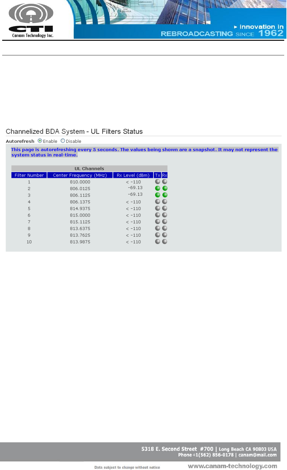
F.2.2 FILTER STATUS PAGE
It shows the incoming Receive Signal Strength (“RSSI”) within each filter
passband window.
Figure 10 – Filter Status page
Filter Number
Processing slot number.
Center Frequency
(MHz)
Filter Center Frequency.
Rx level (dBm)
RSSI meter reading.
Rx Status
Filter Rx Status. Indicator is green is filter Rx Level
is above filter Rx Threshold; grey otherwise.
Tx Status
Filter Tx Status. Indicator is green is filter is
transmitting; grey otherwise.
CANAM TECHNOLOGY, INC. (CTI)
MARK-IVD 800MHZ NARROWBAND SIGNAL BOOSTER M4DBDA8 O&M MANUAL
Page 38 of 46
Rev1 May/2015
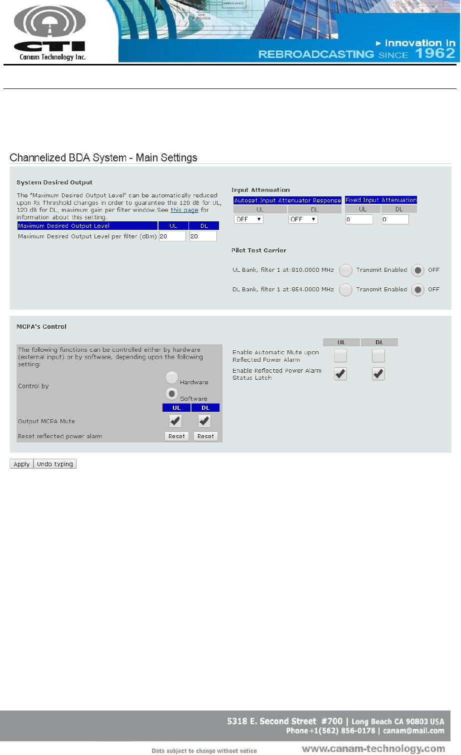
F.2.3 MAIN SETTINGS PAGE
Figure 11 – Main Settings page
The Main Settings page is for configuring general system-level macro settings.
F.2.3.1 Maximum Desired Output Level per filter(dBm):
Allows the configuration of the output level such as the maximum gain
per sub-band will be less than or equal to 120dB.
The specified value cannot be modified in case the maximum gain
would be greater or equal than 120dB.

CANAM TECHNOLOGY, INC. (CTI)
MARK-IVD 800MHZ NARROWBAND SIGNAL BOOSTER M4DBDA8 O&M MANUAL
Page 39 of 46
Rev1 May/2015
The Maximum Desired Output Level is the user setting or goal set point
for the RF Output power level per filter window, subject to the following:
Due to the Automatic Gain Control (AGC) function, the system
calculates the Gain starting at the minimum signal level able to be
received, which is defined by the Rx Threshold (Squelch) setting. Signals
coming in at that threshold level will be amplified a maximum of 120 dB.
Therefore:
o Actual Maximum Desired Output(Set-point) <= Min Rx Threshold +
120dB.
THUS: The User entered Set-point may be automatically reduced
to meet the maximum 120dB Gain. For example, this will happen if
the User reduces an Rx Threshold setting.
o The Desired Output (Set-point) values are limited by this constraint.
o This equation is driven by the lowest Rx Threshold value in the filters
bank, i.e. if at least one filter is set lower than the rest, that value
drives the output Set-Point for the entire bank.
F.2.3.2 Input Attenuation Control
AutoSet Input Attenuator
Response
Select the response speed for the Fixed Input
Attenuator shown in Main Status page.
Fixed Input Attenuation
The fixed input attenuation can be modified
if the “AutoSet Input Attenuator Response” is
OFF. In other modes (FAST, MED and SLOW)
this text field will be disabled and the fixed
input attenuation can change automatically.

CANAM TECHNOLOGY, INC. (CTI)
MARK-IVD 800MHZ NARROWBAND SIGNAL BOOSTER M4DBDA8 O&M MANUAL
Page 40 of 46
Rev1 May/2015
F.2.3.3 Pilot test carrier
The pilot test carrier is related to each bank first channel at current first
channel frequency.
The test carrier may be ON (transmitting) when the pilot test carrier setting is
enabled and the first filter in each bank has checked Tx Enable.
F.2.3.4 MCPA Control:
For the “Output MCPA Mute” and “Reset Reflected Power Alarm Reset”
commands, the user can set the preferred control method by choosing
Software or Hardware in the “Control by” field.
a. If the user chooses hardware control, the controller will respond to the
opto-isolated inputs located in the ECM I/O DB25 Connector and the
software commands for these two parameters will have no effect.
The Reset Reflected Power Alarm command mapped to ECM I/O DB25
Connector can be controlled through pins 3 and 4 for both Service Side
(DL Tx) and Donor Base (UL Tx) outputs.
The Power Amplifier Mute command mapped to ECM I/O DB25
Connector can be controlled through pins 1 and 2 for both Service Side
(DL Tx) and Donor Base (UL Tx) outputs.
When “Control by Hardware” is selected the UL and DL MCPAs are
automatically un-muted unless the corresponding opto-isolated input is
energized.
b. On the other hand, if the user chooses software control, the controller
will respond to these software commands instead of to the opto-isolated
inputs.
Output MCPA Mute
Mute/un-mute MCPA
Reset Reflected Power Alarm
Clear the Reflected Power Alarm Latch.
CANAM TECHNOLOGY, INC. (CTI)
MARK-IVD 800MHZ NARROWBAND SIGNAL BOOSTER M4DBDA8 O&M MANUAL
Page 41 of 46
Rev1 May/2015
Also, there two settings that can be controlled using software commands:
Enable Automatic Mute
upon Reflected Power
Alarm
Check-box to enable/disable automatic
MCPA mute upon excessive reflected power.
Enable Reflected Power
Alarm Status Latch
Check-box to enable/disable the alarm status
latch.
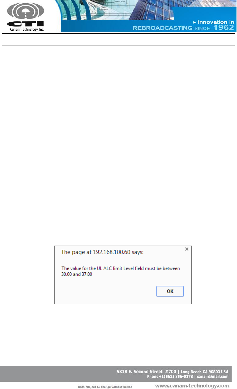
F.2.3.5 Updating operational settings
Write down the desired value in corresponding field.
Using the checkboxes click to check/un-check.
Press enter or “Apply” button for the system to validate the data and
apply changes.
o If the value is not valid, an error message will be displayed (see
Figure 12) and the new value will be not accepted keeping the
previous value.
The current state applied to system is saved to the controller’s internal
nonvolatile memory for effective recovery after a power loss or system
reset.
Figure 12 – Value is not into valid range error message
CANAM TECHNOLOGY, INC. (CTI)
MARK-IVD 800MHZ NARROWBAND SIGNAL BOOSTER M4DBDA8 O&M MANUAL
Page 42 of 46
Rev1 May/2015
F.2.4 FILTER SETTINGS PAGE
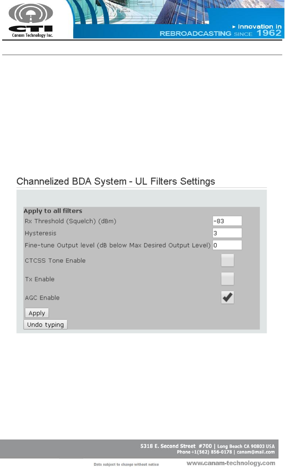
In this page the user can configure the filters as follow:
The “Apply to all filters” section (Figure 13) allows configuring all filters per
bank using the same Rx Threshold, Hysteresis, Fine-Tune Output Level,
CTCSS Tone Enable and Tx/AGC enable status.
Pressing the “Apply” button (it is enabled upon a setting change) the
values in the fields will be applied to all filters.
Figure 13 – Filter Settings page (1/2)
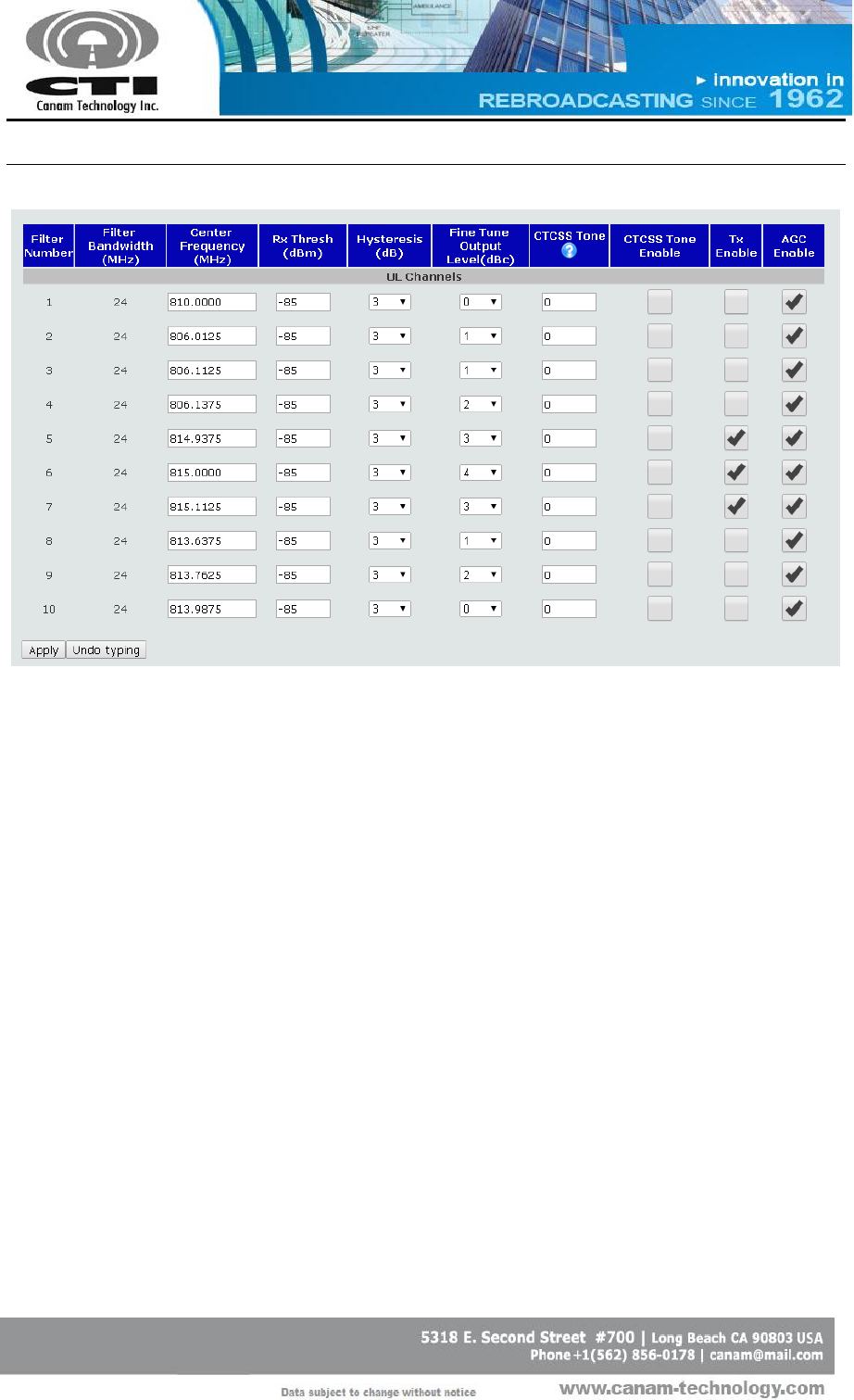
The user may define the settings for each filter window as is shown in
Figure 14.
CANAM TECHNOLOGY, INC. (CTI)
MARK-IVD 800MHZ NARROWBAND SIGNAL BOOSTER M4DBDA8 O&M MANUAL
Page 43 of 46
Rev1 May/2015
Figure 14 – Filter Settings page (2/2)
Filter Number
Read-only attribute. Processing slot number.
Filter Bandwidth (kHz)
Read-only attribute. The filter Bandwidth is
defined by the Filter Configuration currently
loaded.
Center Frequency (MHz)
Filter Center Frequency (MHz).
Rx Threshold (dBm)
Rx Squelch Level.
Hysteresis (dB)
Rx Squelch hysteresis.
Fine-Tune Output Level
(dBc)
It is a fine-tuning control that provides 5 dB
range. It is use to define how many dB below
of Maximum Desired Output Level will the
particular signal be.
CANAM TECHNOLOGY, INC. (CTI)
MARK-IVD 800MHZ NARROWBAND SIGNAL BOOSTER M4DBDA8 O&M MANUAL
Page 44 of 46
Rev1 May/2015
CTCSS Tone
CTCSS Tone Frequency. In order to choose
the tone frequency, write one of the codes
shown in Table 7. Also, this table will be
shown in a pop up window when you pass
the mouse pointer over symbol.
CTCSS Tone Enable
CTCSS enable/disable.
Tx Enable
Transmitter ON/OFF.
AGC Enable
Automatic Gain Control ON/OFF.
Table 7 – CTCSS Tone frequency codes.
Code
CTCSS
Frequency (Hz)
Code
CTCSS
Frequency (Hz)
0
67.0
21
136.5
1
69.3
22
141.3
2
71.9
23
146.2
3
74.4
24
151.4
4
77.0
25
156.7
5
79.7
26
162.2
6
82.5
27
167.9
7
85.4
28
173.8
8
88.5
29
179.9
9
91.5
30
186.2
10
94.8
31
192.8
11
97.4
32
203.5
12
100.0
33
206.5
13
103.5
34
210.7
14
107.2
35
218.1
15
110.9
36
225.7
16
114.8
37
229.1
17
118.8
38
233.6
18
123.0
39
241.83
19
127.3
40
250.33
20
131.8
41
254.13
CANAM TECHNOLOGY, INC. (CTI)
MARK-IVD 800MHZ NARROWBAND SIGNAL BOOSTER M4DBDA8 O&M MANUAL
Page 45 of 46
Rev1 May/2015
Useful Tips for configuring Filters
Center frequency corresponds to the filter-window center. For
narrowband windows, please make sure the programmed frequency
corresponds to the actual radio signal frequency to avoid interference.
The Fine Tune Output Level setting is used for adjusting down the carrier
power level on an individual “per-window” basis, and provides around
5 dB fine-tuning range.
How to update operational settings?
Write down the desired value in corresponding field.
Press enter or “Apply” button for the system to validate the data and
apply changes.
Using the checkboxes click once and then press “Apply” button.
CANAM TECHNOLOGY, INC. (CTI)
MARK-IVD 800MHZ NARROWBAND SIGNAL BOOSTER M4DBDA8 O&M MANUAL
Page 46 of 46
Rev1 May/2015
(This Page was intentionally left blank)