Canam Technology M4DBDAV MARK-IV Digital Narrowband (Class-A) Signal Booster User Manual UHF CHANNELIZED OUTPUT LIMIT CONTROL
Canam Technology, Inc MARK-IV Digital Narrowband (Class-A) Signal Booster UHF CHANNELIZED OUTPUT LIMIT CONTROL
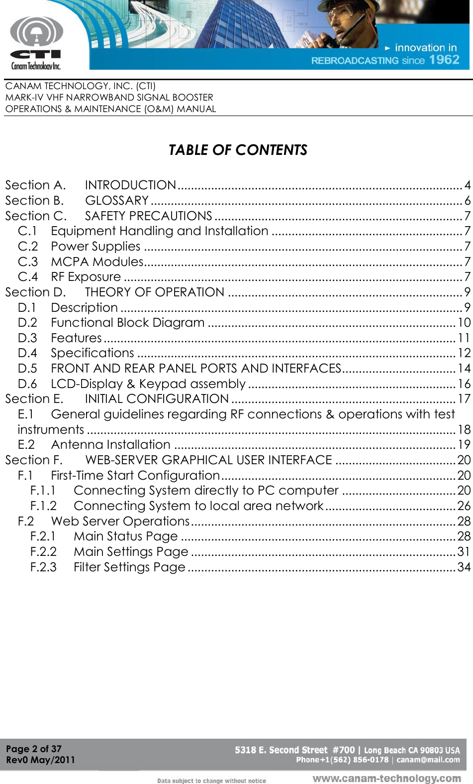
Contents
- 1. Users Manual
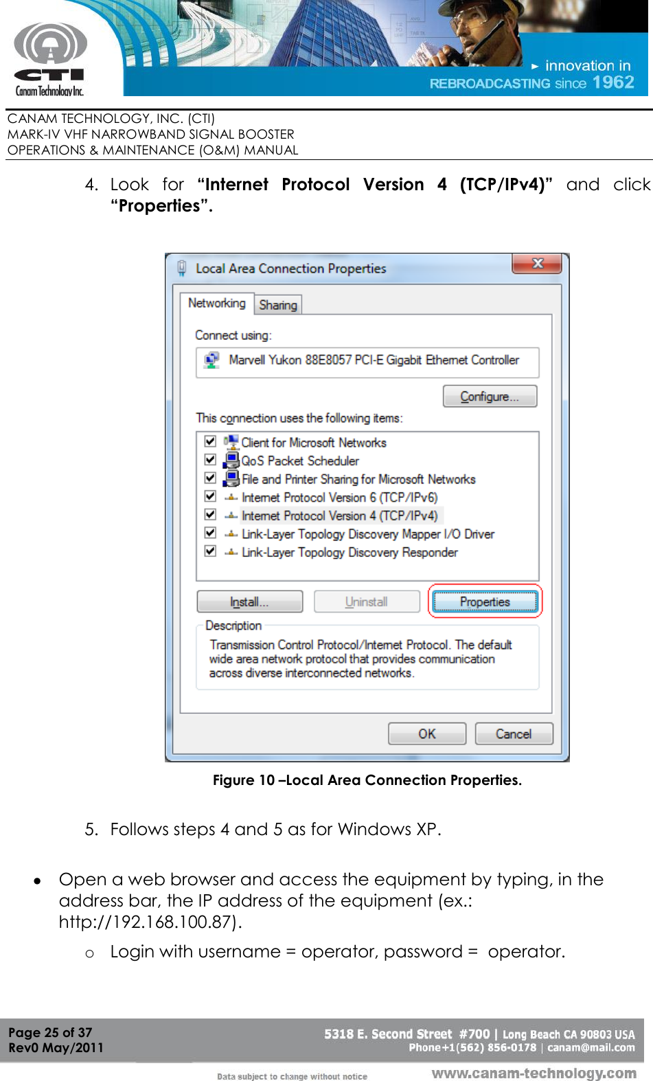
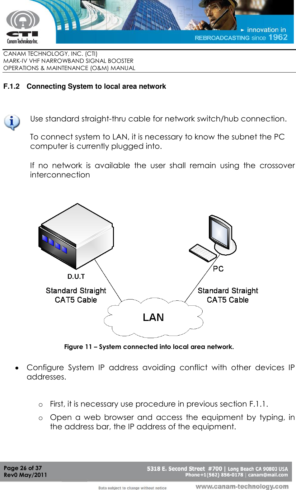
- 2. Operational and maintenance manual
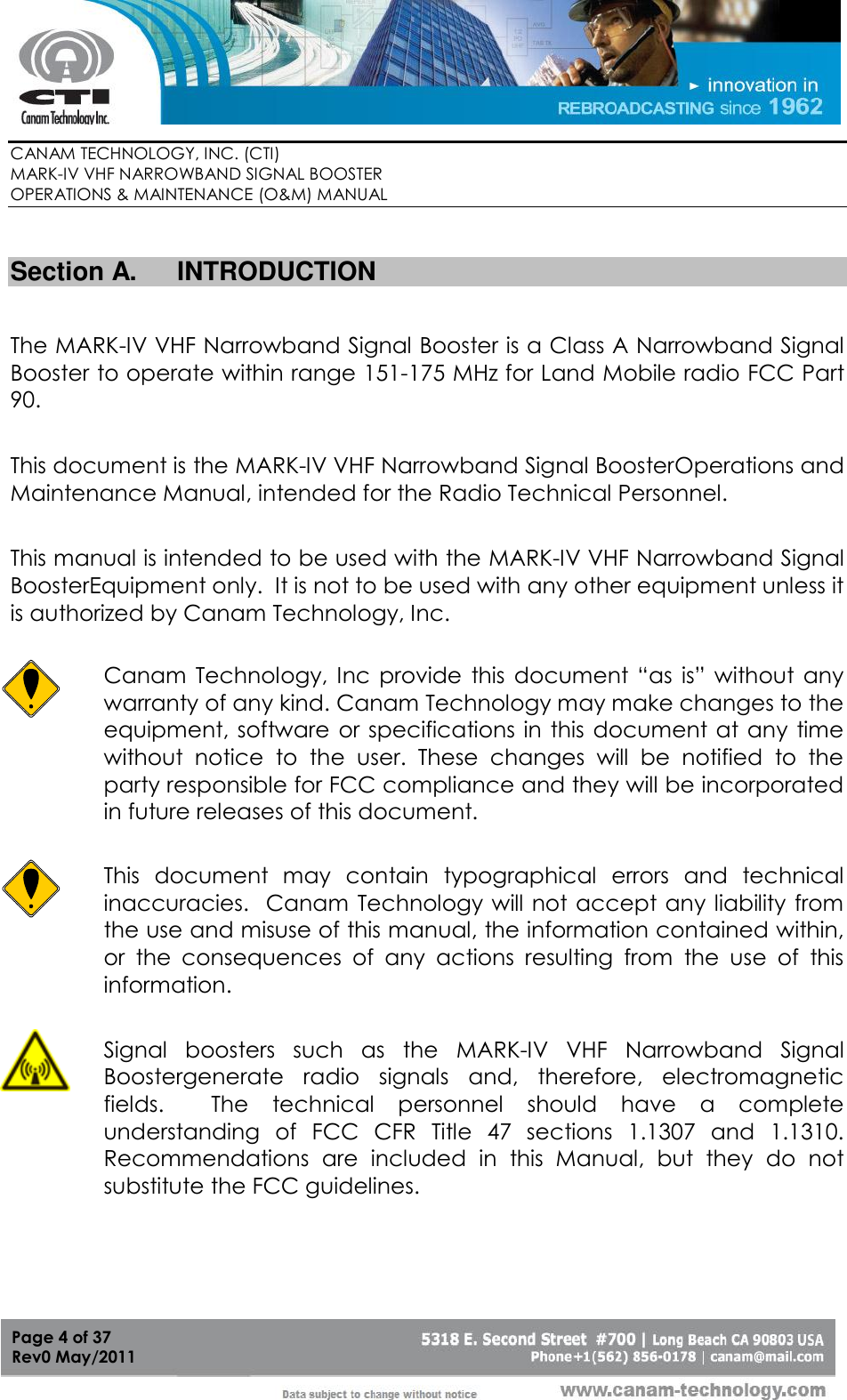
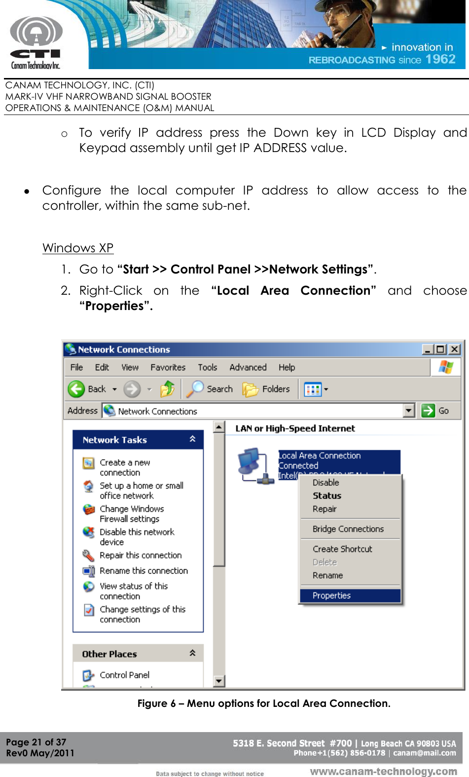
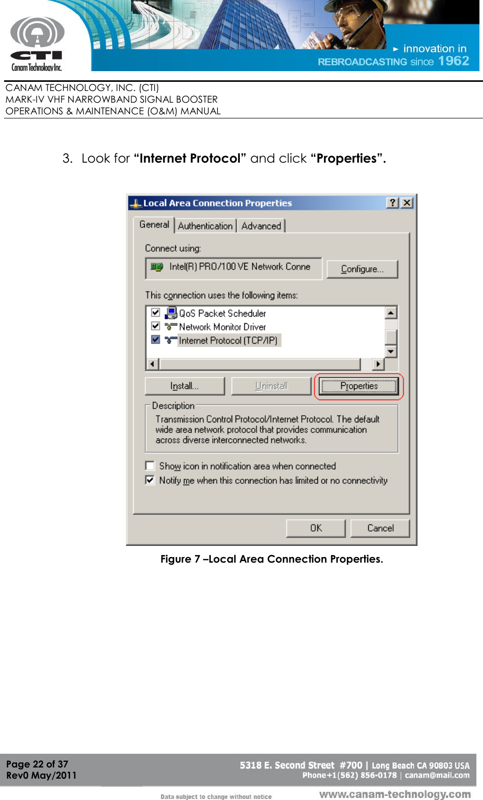
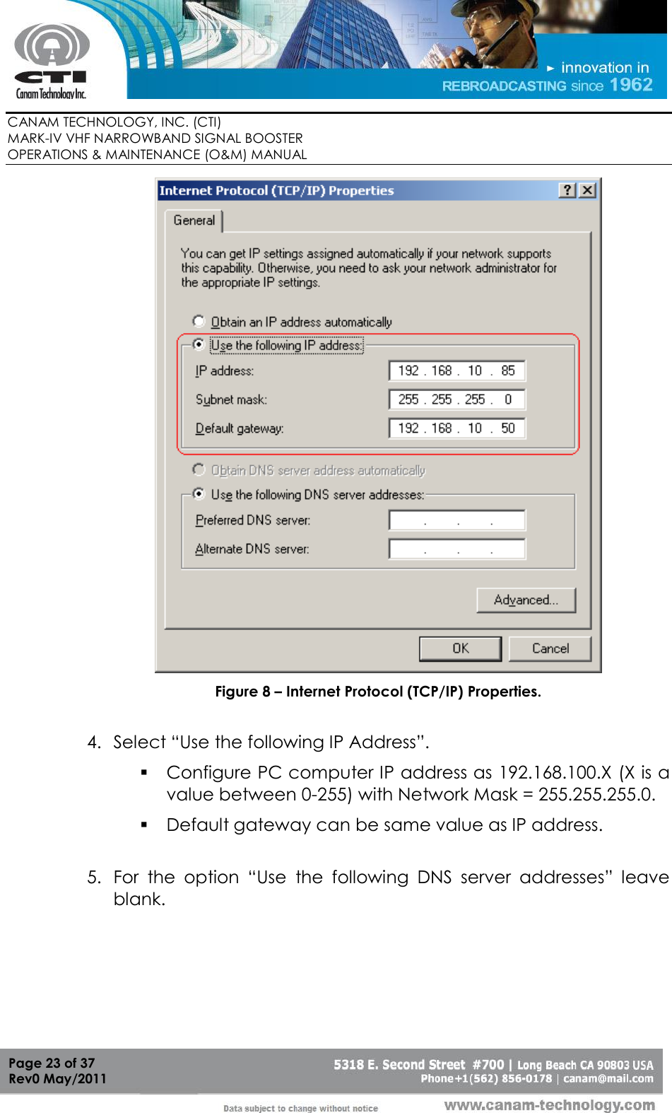
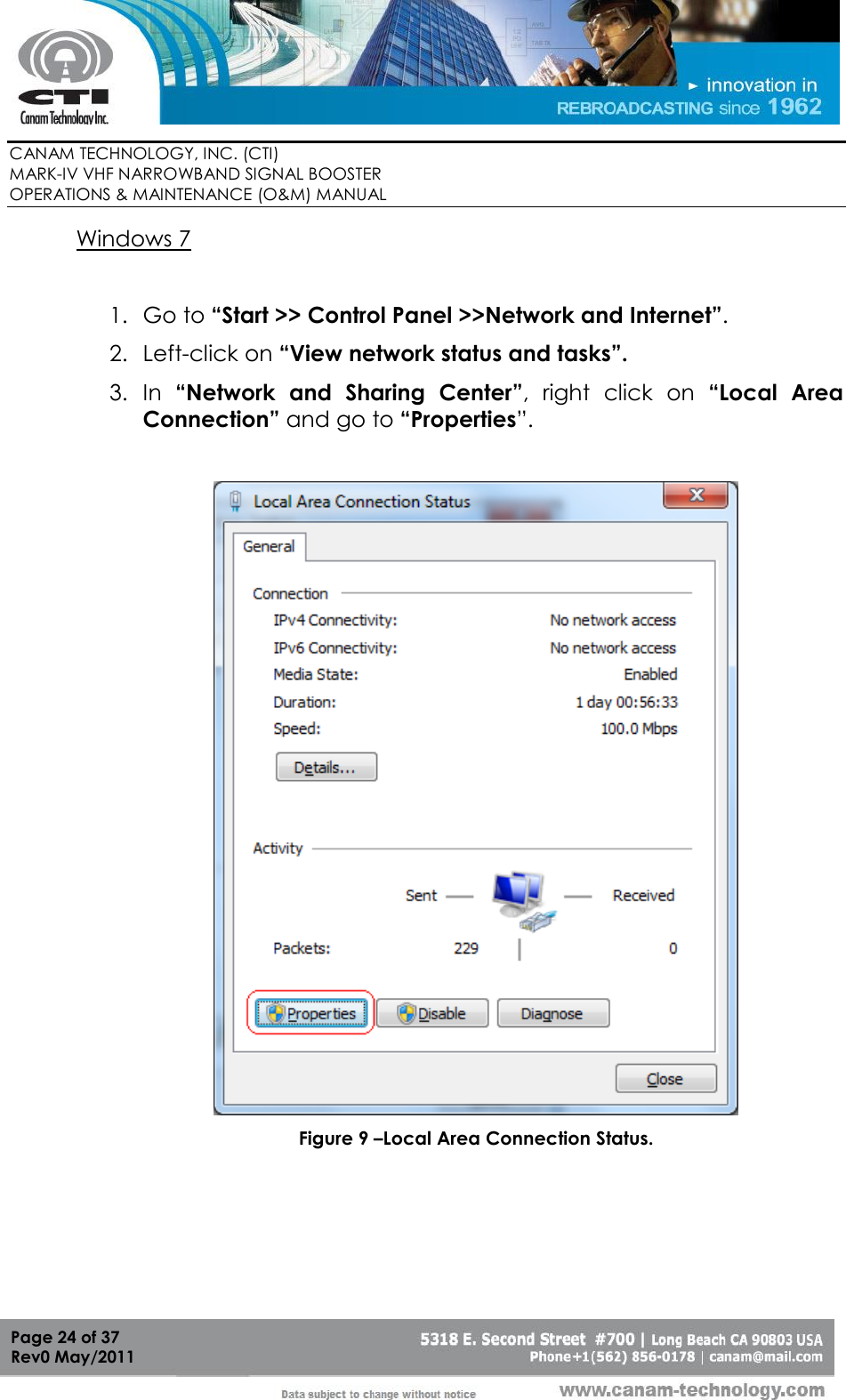
Operational and maintenance manual