Canon Copier Fy8 13Ex 000 Users Manual Ppre
FY8-13EX-000 to the manual ab817b7c-a77d-4ef4-a507-c3ae8fab7819
2015-01-23
: Canon Canon-Copier-Fy8-13Ex-000-Users-Manual-240997 canon-copier-fy8-13ex-000-users-manual-240997 canon pdf
Open the PDF directly: View PDF ![]() .
.
Page Count: 389 [warning: Documents this large are best viewed by clicking the View PDF Link!]

SERVICE
MANUAL
REVISION 0
FY8-13EX-000
MAY 1997
COPYRIGHT © 1997 CANON INC. CANON NP6218 REV.0 MAY 1997 PRINTED IN JAPAN (IMPRIMÉ AU JAPON)

IMPORTANT
THIS DOCUMENTATION IS PUBLISHED BY CANON INC., JAPAN, TO SERVE AS A SOURCE OF
REFERENCE FOR WORK IN THE FIELD.
SPECIFICATIONS AND OTHER INFORMATION CONTAINED HEREIN MAY VARY SLIGHTLY FROM
ACTUAL MACHINE VALUES OR THOSE FOUND IN ADVERTISING AND OTHER PRINTED MATTER.
ANY QUESTIONS REGARDING INFORMATION CONTAINED HEREIN SHOULD BE DIRECTED TO
THE COPIER SERVICE DEPARTMENT OF THE SALES COMPANY.
THIS DOCUMENTATION IS INTENDED FOR ALL SALES AREAS, AND MAY CONTAIN
INFORMATION NOT APPLICABLE TO CERTAIN AREAS.
COPYRIGHT © 1997 CANON INC.
Printed in Japan
Imprimé au Japon
Use of this manual should be strictly
supervised to avoid disclosure of
confidential information.
Prepared by
OFFICE IMAGING PRODUCTS TECHNICAL SUPPORT DEPT. 1
OFFICE IMAGING PRODUCTS TECHNICAL SUPPORT DIV.
CANON INC.
5-1, Hakusan 7-chome, Toride-shi, Ibaraki 302 Japan
COPYRIGHT © 1997 CANON INC. CANON NP6218 REV.0 MAY 1997 PRINTED IN JAPAN (IMPRIMÉ AU JAPON)

This Service Manual contains the bsic facts and figures about the plain paper copier
NP6218, and is compiled to serve as a handy reference for servicing the machine in the
field.
The NP6218 is designed to enable fully automated copying work and may be
configured with the following accessories:
1. Cassette Feeding Module-B2*
2. Cassette Feeding Module-A2*
3. Control Card IV N
4. ADF-E1
5. Staple Sorter B2/D1
6. MS-B1
7. Remote Diagnostic Device II
This manual is limited to the descriptions of the NP6218, Cassette Feeding Module-
B2/Cassette Feeding Module-A2.
* May not be available in some areas but discussed in this manual.
This Service Manual covers the copier only, and consists of the following chapters:
Chapter 1
General Description
introduces the copier's features and specifications,
shows how to operate the copier, and explains how copies are made.
Chapter 2
Basic Operation
provides outlines of the copier's various mechanical
workings.
Chapter 3
Exposure System
discusses the principles of operation used for the
copier's lens drive unit and scanner drive unit. It also explains the timing
at which these drive units are operated, and shows how they may be
disassembled/assembled and adjusted.
Chapter 4
Image Formation System
discusses the principles of how images are
formed. It also explains the timing at which the various units involved in
image formation are operated, and shows how they may be
disassembled/assembled and adjusted.
Chapter 5
Pick-Up/Feeding System
explains the principles used from when copy
paper is picked up to when a copy is delivered in view of the functions of
electrical and mechanical units and in relation to their timing of operation.
It also shows how these units may be disassembled/assembled and
adjusted.
Chapter 6
Fixing System
explains the principles used to fuse toner images to
transfer media in view of the functions of electrical and mechanical units
and in relation to their timing of operation. It also shows how these units
may be disassembled/assembled and adjusted.
Chapter 7
Externals/Auxiliary Mechanisms
shows the copier's external parts, and
explains the principles used for the copier's various control mechanisms
in view of the functions of electrical and mechanical units and in relation
to their timing of operation. It also shows how these units may be
disassembled/assembled and adjusted.
Chapter 8
Installation
introduces requirements for the site of installation, and shows
how the copier may be installed using step-by-step instructions.
INTRODUCTION
COPYRIGHT © 1997 CANON INC. CANON NP6218 REV.0 MAY 1997 PRINTED IN JAPAN (IMPRIMÉ AU JAPON)
i

Chapter 9
Maintenance and Servicing
provides tables of periodically replaced parts
and consumables/durables and scheduled servicing charts.
Chapter 10
Troubleshooting
provides tables of maintenance/inspection,
standards/adjustments, and problem identification (image
fault/malfunction).
Appendix contains a general timing chart and general circuit diagrams.
In addition to the above chapters, this SERVICE MANUAL contains a set of
appendixes consisting of a general timing chart and general circuit diagrams.
A separate document entitled SERVICE HANDBOOK is also available for
troubleshooting problems in the copier.
The following rules apply throughout this volume:
1. Each chapter contains sections explaining the purpose of specific functions and the
relationship between electrical and mechanical systems with reference to the
timing of operation.
In the diagrams, represents the path of mechanical drive—where a
signal name accompanies the symbol , the arrow indicates the direction
of the electric signal.
The expression “turn on the power” means flipping on the power switch, closing the
front door, and closing the delivery unit door, which will result in supplying the
machine with power.
2. In the digital circuits, ‘1’ is used to indicate that the voltage level of a given signal is
“High,” while ‘0’ is used to indicate “Low.” (The voltage value, however, differs from
circuit to circuit.)
In practically all cases, the internal mechanisms of a microprocessor cannot be
checked in the field. Therefore, the operations of the microprocessors used in the
machines are not discussed: they are explained in terms of from sensors to the
input of the DC controller PCB and from the output of the DC controller PCB to the
loads.
The contents of this manual may be updated from time to time to reflect improvements
rendered to the copier; a Service Information bulletin will be issued as necessary to
cover major changes.
All service persons are expected to be thoroughly familiar with the information
contained in this manual, SERVICE HANDBOOK, and Service Information bulletins, for
quick response to the user’s needs.
COPYRIGHT © 1997 CANON INC. CANON NP6218 REV.0 MAY 1997 PRINTED IN JAPAN (IMPRIMÉ AU JAPON)
ii
System Configuration
The NP6218 may be configured with the following systems options:
COPYRIGHT © 1997 CANON INC. CANON NP6218 REV.0 MAY 1997 PRINTED IN JAPAN (IMPRIMÉ AU JAPON)
iii
ADF-E1
Sends originals one by one from
a stack set on its tray
Stapler Sorter B2/D1, MS-B1
Automatically sorts or (page collation)
or groups up to 10 sets of copies;
with the sorting function,
the sorted copies may
automatically be stapled.
(Not applicable to MS-B1.)
Control Card IV N
Allows the user to control
copy volume.
Cassette Feeding Module-A2
Adds additional two cassettes.
Cassette Feeding Module-B2
Adds an additional cassette.

1. GENERAL DESCRIPTION
COPYRIGHT © 1997 CANON INC. CANON NP6218 REV.0 MAR. 1997 PRINTED IN JAPAN (IMPRIMÉ AU JAPON)
iv

COPYRIGHT © 1997 CANON INC. CANON NP6218 REV.0 MAY 1997 PRINTED IN JAPAN (IMPRIMÉ AU JAPON)
v
CONTENTS
CHAPTER 1 GENERAL DESCRIPTION
I. FEATURES.........................................1-1
II. SPECIFICATIONS ..............................1-2
A. Copier............................................1-2
1. Type..........................................1-2
2. System .....................................1-2
3. Features ...................................1-3
4. Others.......................................1-4
B. Cassette Feeding Module-B2/
Cassette Feeding Module-A2........1-5
III. NAMES OF PARTS ............................1-6
A. Exterior View .................................1-6
B. Cross Section ................................1-7
1. Body .........................................1-7
2. Cassette Feeding Module-A2...1-8
IV. OPERATION.......................................1-9
A. Control Panel.................................1-9
B. Operation Mode.............................1-10
C. Making Two-Sided/Overlay
Copies (manual) ............................1-11
D. User Mode.....................................1-12
1. Outline ......................................1-12
2. Common Operations ................1-13
3. Changing the Auto Clear
Time ( ) ..............................1-13
4. Changing the Auto Power-Off
Time ( ) ..............................1-13
5. Zoom Fine-Adjustment ( )..1-14
6. Turning On and Off the Auto
Cassette Change Mechanism
( ) .......................................1-15
7. Turning On/Off the Auto Sort/
Non-Sort (with ADF and sorter
installed—option) ( ) ..........1-16
8. Cleaning the Feeder (with ADF
installed—option) ( ) ..........1-16
9. Selecting the Density
Adjustment Method for
Standard Mode ( ) .............1-17
10.Initializing User Mode ( )....1-17
11.Quick Guide to User Mode.......1-18
E. Handling the Toner Bottle..............1-19
V. WARNINGS AND ACTIONS ..............1-19
VI. ROUTINE MAINTENANCE BY THE
USER..................................................1-19
VII. IMAGE FORMATION..........................1-20
A. Outline ...........................................1-20
CHAPTER 2 BASIC OPERATION
I. BASIC CONSTRUCTION...................2-1
A. Functional Construction.................2-1
B. Outline of the Electrical Circuitry...2-2
C. Basic Sequence of Operations
(2 copies continuous, AE) .............2-3
D. Main Motor Control Circuit.............2-4
1. Outline ......................................2-4
2. Mechanism ...............................2-4
E. Inputs to the DC Controller PCB ...2-5
1. Inputs to the DC Controller
PCB (1/3)..................................2-5
2. Inputs to the DC Controller
PCB (2/3)..................................2-6
3. Inputs to the DC Controller
PCB (3/3)..................................2-7
F. Outputs from the DC Controller
PCB ...............................................2-8
1. Outputs from the DC
Controller PCB (1/3).................2-8
2. Outputs from the DC
Controller PCB (2/3).................2-9
3. Outputs from the DC
Controller PCB (3/3).................2-10
G. Inputs to and Outputs from the
1-Cassette Unit Driver PCB...........2-11
1. Inputs to and Outputs from
the 1-Cassette Unit Driver
PCB (1/1)..................................2-11
H. Inputs to and Outputs from the
2-Cassette Unit Driver PCB...........2-12
1. Inputs to and Outputs from
the 2-Cassette Unit Driver
PCB (1/2)..................................2-12
2. Inputs to and Outputs from
the 2-Cassette Unit Driver
PCB (2/2)..................................2-13

COPYRIGHT © 1997 CANON INC. CANON NP6218 REV.0 MAY 1997 PRINTED IN JAPAN (IMPRIMÉ AU JAPON)
vi
I. PROCESSES .....................................4-1
A. Outline ...........................................4-1
B. Basic Sequence of Operations
(image formation system)..............4-3
C. Controlling the Scanning Lamp .....4-4
1. Outline ......................................4-4
2. Turning On and Off the
Scanning Lamp ........................4-5
3. Pre-Heating Control
(scanning lamp)........................4-5
4. Sequence of Operations
(scanning lamp pre-heating
control; AE, A4, continuous,
2 copies)...................................4-5
5. Controlling the Intensity of the
Scanning Lamp (FL1)...............4-7
6. Controlling the Fluorescent
Lamp Heater.............................4-8
7. Fluorescent Lamp Automatic ...4-9
8. Fluorescent Lamp Protection
Mechanism ...............................4-9
D. Controlling the Primary Charging
Roller Bias .....................................4-10
1. Outline ......................................4-10
2. Turning On and Off the Primary
Charging Roller Bias ................4-11
3. Controlling the Primary
Charging Roller Bias to a
Constant Voltage ......................4-11
4. Switching the Primary Charging
Roller Bias Application Voltage
Level .........................................4-11
5. Application Voltage Level
(APVC) for the Primary
Charging Roller and Scanning
Lamp On Voltage Level
Automatic Correction................4-12
E. Controlling the Transfer Roller Bias...4-13
1. Outline ......................................4-13
2. Turning On and Off the
Transfer Roller Bias..................4-15
3. Controlling the Transfer Bias
to a Constant Voltage...............4-15
4. Controlling the Transfer Bias
Voltage Level Correction
(ATVC control) ..........................4-15
5. Current Limiter Circuit
(transfer bias) ...........................4-15
6. Current Limiter Circuit
(cleaning bias)..........................4-15
F. Controlling the Static Eliminator
Bias................................................4-16
CHAPTER 4 IMAGE FORMATION SYSTEM
CHAPTER 3 EXPOSURE SYSTEM
I. BASIC OPERATION ...........................3-1
A. Varying the Reproduction Ratio ....3-1
II. LENS DRIVE SYSTEM ......................3-1
A. Outline ...........................................3-1
B. Lens Motor Drive Circuit................3-3
1. Keeping the Lens Motor
Stationary .................................3-3
2. Driving the Lens Motor.............3-3
C. Basic Sequence of Operations
(lens drive system; non-Direct)......3-4
III. SCANNING DRIVE SYSTEM.............3-5
A. Driving the Scanner.......................3-5
1. Outline ......................................3-5
2. Relationship between the
Scanner Sensor and Signals....3-6
3. Basic Sequence of
Operations (scanner)................3-6
4. Driving the Scanner Motor .......3-7
5. Scanner Operations in Page
Separation Mode (non-AE,
page separation, A4, 2 copies)..3-8
IV. DISASSEMBLY AND ASSEMBLY ......3-9
A. Scanner Drive Assembly ...............3-9
1. Detaching the Scanner Drive
Motor ........................................3-9
2. Detaching the Scanner Cable ..3-10
3. Assembling the Mirror
Position Tool .............................3-12
4. Routing the Scanner Cable......3-13
5. Adjusting the Position of the
Mirrors (optical length of No.
1, 2, and 3 mirrors)...................3-16
6. Cleaning the Scanner No. 6
Mirror ........................................3-17
B. Lens Drive Assembly.....................3-18
1. Detaching the Lens Drive
Motor ........................................3-18
2. Routing the Lens Cable............3-20
3. Adjusting the Position of the
Change Solenoid......................3-21

COPYRIGHT © 1997 CANON INC. CANON NP6218 REV.0 MAY 1997 PRINTED IN JAPAN (IMPRIMÉ AU JAPON)
vii
1. Outline ......................................4-16
2. Switching the Static Eliminator
Bias Voltage Level ....................4-17
3. Ensuring Proper Separation of
Thin Paper................................4-17
G. Controlling Blank Exposure...........4-18
1. Outline ......................................4-18
2. Blanking (Whiting) of Non-
Image Areas for Reduction.......4-19
3. Blanking (Whiting) Out the
Leading/Trailing Edges and
between Copies........................4-19
H. Controlling the Primary Corona
Roller Cleaning Mechanism ..........4-20
1. Outline ......................................4-20
2. Primary Charging Roller
Cleaning Operation ..................4-20
I. Releasing the Transfer Roller ........4-21
1. Outline ......................................4-21
II. DEVELOPING ASSEMBLY AND
CLEANING ASSEMBLY .....................4-22
A. Outline ...........................................4-22
B. Controlling the Toner Level
Detection .......................................4-23
C. Controlling the Development
Bias................................................4-25
1. Outline ......................................4-25
2. Turning On and Off the DC
Component of the Developing
Bias and Controlling the
Voltage to a Constant Level .....4-25
3. Turning On and Off the AC
Component of the
Development Bias ....................4-26
4. Controlling the Voltage Level
of the DC Component of the
Development Bias ....................4-26
D. Automatic Control of Copy
Density...........................................4-27
1. Outline ......................................4-27
2. Control Method.........................4-27
3. AE Adjustment..........................4-29
III. DISASSEMBLY AND ASSEMBLY ......4-30
A. Illumination Assembly....................4-30
1. Detaching the Scanning
Lamp/Fluorescent Lamp
Heater.......................................4-30
2. Points to Note When Attaching
the Fluorescent Lamp
Heater/Scanning Lamp.............4-32
3. Detaching the Blank Exposure
Assembly..................................4-34
4. Detaching the Blank Exposure
Lamp ........................................4-35
5. Detaching the Blank Shutter
Solenoid ...................................4-36
6. Positioning the Blank Shutter
Solenoid ...................................4-37
7. Routing the Blanking Cable......4-38
8. Positioning the Left/Right
Margin ......................................4-38
B. Drum Unit ......................................4-39
1. Detaching the Drum Unit..........4-39
2. Cleaning ...................................4-40
C. Primary Corona Assembly.............4-41
1. Detaching the Primary Corona
Assembly..................................4-41
2. Cleaning the Cleaning Pad and
the Primary Corona Roller .......4-42
3. Positioning the Solenoid for the
Primary Charging Roller...........4-43
D. Transfer Charging Assembly .........4-44
1. Detaching the Transfer Roller...4-44
2. Attaching the Drum Heater.......4-44
E. Developing System........................4-47
1. Removing the Developing
Assembly..................................4-47
2. Removing the Blade
Assembly..................................4-47
3. Removing the Developing
Cylinder Side Seal....................4-48
4. Installing the Side Seal and
the Blade Assembly..................4-51
CHAPTER 5 PICK-UP/FEEDING SYSTEM
I. PICK-UP/FEEDING SYSTEM ............5-1
A. Outline ...........................................5-1
II. PICK-UP OPERATION (COPIER)......5-3
A. Outline ...........................................5-3
B. Sequence of Operations (pick-up/
feeding assembly; A4, 2 copies)....5-4
III. PICK-UP FROM THE CASSETTE
FEEDING MODULE-A2......................5-5
A. Pick-Up Operation .........................5-5
B. Sequence of Operations
(cassette 2; A4, 2 copies)..............5-6
IV. MULTIFEEDER...................................5-7
A. Outline ...........................................5-7
B. Identifying the Size of Paper on
the Multifeeder...............................5-8
C. Sequence of Operations
(multifeeder; A4, 2 copies).............5-9
V. IDENTIFYING THE CASSETTE
SIZE....................................................5-10
VI. IDENTIFYING JAMS ..........................5-12
A. Pre-Registration Delay Jam...........5-12
B. Pre-Registration Timing Jam .........5-13

COPYRIGHT © 1997 CANON INC. CANON NP6218 REV.0 MAY 1997 PRINTED IN JAPAN (IMPRIMÉ AU JAPON)
viii
C. Pre-Registration Stationary Jam ...5-13
D. Separation Delay Jam ...................5-14
E. Separation Stationary Jam............5-14
F. Delivery Delay Jam........................5-15
G. Delivery Stationary Jam ................5-15
VII. DISASSEMBLY AND ASSEMBLY ......5-16
A. Pick-Up Assembly .........................5-16
1. Detaching the Pick-Up Roller
Unit ...........................................5-16
2. Detaching the Pick-Up Roller...5-19
3. Points to Note When Attaching
the Pick-Up Roller ....................5-20
4. Detaching the Pick-Up Clutch...5-20
5. Detaching the Separation Pad..5-21
6. Adjusting the Left/Right
Registration ..............................5-22
B. Multifeeder Assembly ....................5-23
1. Detaching the Multifeeder
Assembly..................................5-23
2. Detaching the Multifeeder
Pick-Up Roller Unit...................5-24
3. Detaching the Multifeeder
Pick-Up Roller ..........................5-25
4. Points to Keep Note When
Attaching the Multifeeder
Pick-Up Roller ..........................5-26
5. Detaching the Separation Pad..5-26
6. Detaching the Multifeeder
Drive Unit..................................5-27
7. Detaching the Multifeeder
Clutch .......................................5-28
8. Positioning the Multifeeder
Assembly (paper guide plate
cam) .........................................5-29
9. Adjusting the Left/Right
Registration ..............................5-30
10.Points to Note When Attaching
the Multifeeder Assembly Rack
Plate .........................................5-30
C. Registration Roller Assembly ........5-31
1. Detaching the Registration
Clutch .......................................5-31
2. Detaching the Upper
Registration Roller....................5-31
3. Detaching the Lower
Registration Roller....................5-33
D. Feeding Assembly.........................5-34
1. Detaching the Feeding Belt......5-34
E. Cassette Unit.................................5-36
1. Detaching the Copier from
the Cassette Unit......................5-36
2. Detaching/Attaching the
Pick-Up Roller ..........................5-36
3. Detaching the Pick-Up Clutch ..5-36
CHAPTER 6 FIXING SYSTEM
I. BASIC OPERATIONS.........................6-1
A. Outline ...........................................6-1
B. Controlling the Fixing Heater
Temperature ..................................6-3
C. Controlling the Supply Power for
the Fixing Heater...........................6-5
D. Detecting Overheating at the End
of the Fixing Heater.......................6-6
E. Protection Mechanism...................6-6
1. Thermistor (TH1, TH2) .............6-6
2. Thermal Fuse (FU1).................6-6
3. Heater ON Detection Circuit
(230V model only) ....................6-6
F. Correcting Displacement of the
Fixing Film .....................................6-7
1. Outline ......................................6-7
2. Controlling the Fixing Film
Motor ........................................6-10
II. DISASSEMBLY AND ASSEMBLY ......6-11
A. Fixing Assembly ............................6-11
1. Construction1 ...........................6-11
2. Detaching the Upper Fixing
Unit ...........................................6-12
3. Detaching the Fixing Film,
Tension Roller, Drive Roller,
Fixing Cleaning Brush, and
Fixing Heater Unit ....................6-13
4. Points to Note When Attaching
the Fixing Film .........................6-20
5. Points to Note When Attaching
the Heater Connector...............6-20
6. Points to Note When Replacing
the Fixing Upper Unit ...............6-21
7. Adjusting the Fixing Film Drive
Roller Pressure.........................6-21
8. Detaching the Lower Fixing
Unit ...........................................6-23
9. Detaching the Separation
Claw/Lower Fixing Claw and
Fixing Cleaning Roller ..............6-24
10.Adjusting the Lower Fixing
Roller Nip..................................6-25
B. Delivery Assembly.........................6-27

COPYRIGHT © 1997 CANON INC. CANON NP6218 REV.0 MAY 1997 PRINTED IN JAPAN (IMPRIMÉ AU JAPON)
ix
CHAPTER 7 EXTERNALS/AUXILIARY MECHANISMS
I. POWER SUPPLY ...............................7-1
A. Outline ...........................................7-1
B. Power Supply Circuit Assembly.....7-2
C. Detecting Errors in the Power
Supply PCB ...................................7-4
1. Communication Error between
DC Controller PCB and
Composite Power Supply PCB ..7-4
2. Error in the High-Voltage
Output Data..............................7-4
3. Low-Voltage Output Data Error..7-4
4. Overcurrent in the Low-voltage
Power Supply ...........................7-4
D. Protection Mechanisms for the
Power Supply Circuit .....................7-5
II. DISASSEMBLY AND ASSEMBLY ......7-6
A. External Covers.............................7-6
B. Control Panel.................................7-9
1. Detaching the Control Panel ....7-9
C. Fans...............................................7-10
1. Detaching the Exhaust Fan......7-10
D. Main Motor/Main Drive Assembly..7-11
1. Detaching the Main Motor Unit..7-11
2. Detaching the Main Drive
Assembly..................................7-11
3. Routing the Drive Belt ..............7-13
E. Cassette unit .................................7-14
1. Detaching the Pick-Up Drive
Unit ...........................................7-14
2. Detaching the Cassette Motor..7-15
3. Detaching the Cassette Driver
PCB ..........................................7-16
F. DC Controller PCB ........................7-17
1. Detaching the DC Controller
PCB ..........................................7-17
2. Points to Note When
Replacing the DC Controller
PCB ..........................................7-17
G. Composite Power Supply PCB......7-18
1. Detaching the Composite
Power Supply PCB...................7-18
2. Points to Note When Handling
the Composite Power Supply
PCB ..........................................7-20
H. AE Sensor PCB.............................7-21
1. Points to Note When
Replacing the AE Sensor.........7-21
I. Intensity Sensor PCB ....................7-21
1. Points to Note When Replacing
the Intensity Sensor .................7-21
I. SELECTING THE SITE ......................8-1
II. UNPACKING AND INSTALLING
THE COPIER......................................8-2
A. Unpacking and Removing Fixings..8-2
B. Turning On the Copier ...................8-5
C. Checking the Images and
Operations.....................................8-8
D. Attaching the Drum Unit ................8-9
E. Changing the Cassette Size..........8-10
III. RELOCATING THE COPIER..............8-13
IV. REPLACING THE DRUM UNIT..........8-14
V. INSTALLING THE CONTROL CARD
IV N.....................................................8-17
VI. CASSETTE HEATER KIT 5
INSTALLATION PROCEDURE...........8-19
A. Unpacking......................................8-19
B. Installation (to a Cassette
Feeding Module-A2/B2).................8-20
VII. INSTALLING THE REMOTE
DIAGNOSTIC DEVICE II....................8-26
A. Unpacking......................................8-26
B. Installation to the Copier ...............8-27
CHAPTER 8 INSTALLATION
CHAPTER 9 MAINTENANCE AND SERVICING
I. PERIODICALLY REPLACED
PARTS ................................................9-1
A. Periodically Replaced Parts...........9-1
II. DURABLES ........................................9-2
A. Copier............................................9-2
B. Cassette Feeding Module-B2/
Cassette Feeding Module-A2........9-3
III. PERIODICAL SERVICING .................9-4
IV. SERVICING CHART...........................9-5
V. NOTES ON DRUM KIT ......................9-6

COPYRIGHT © 1997 CANON INC. CANON NP6218 REV.0 MAY 1997 PRINTED IN JAPAN (IMPRIMÉ AU JAPON)
x
CHAPTER 10 TROUBLESHOOTING
I. MAINTENANCE AND INSPECTION..10-3
A. Image Adjustment Basic
Procedure....................................10-3
B. Periodical Servicing.....................10-4
II. STANDARDS AND ADJUSTMENTS..10-5
A. Image Adjustment .......................10-5
1. Adjusting the Image Leading
Edge Margin ([3], No.305;
registration ON timing) ...........10-5
2. Adjusting the Leading Edge
Non-Image Width ([3], No.
306; blank shutter ON
timing).....................................10-6
3. Adjusting the Image Trailling
Edge Non-Image Width ([3],
No.309; blank shutter
timing).....................................10-7
4. Adjusting the Left/Right
Registration ............................10-8
5. Adjusting the Left/Right Margin
(No.311; left/right margin).......10-9
6. Adjusting the Scanning Lamp
Intensity..................................10-10
7. AE Adjustment .......................10-11
B. Exposure System ........................10-15
1. Routing the Scanner Drive
Cable......................................10-15
2. Adjusting the Mirror Position
optical distance between No.1
mirror and No.2/No.3 mirror) ..10-16
3. Adjusting the Scanner Cable
Tension ...................................10-17
4. Assembling the Mirror
Positioning Tool ......................10-17
5. Points to Note When Attaching
the Fluorescent Lamp Heater/
Scanning Lamp ......................10-18
6. Positioning the Change
Solenoid .................................10-20
C. Image Formation System ............10-21
1. Positioning the Blank Shutter
Solenoid .................................10-21
2. Routing the Blank Shutter
Cable......................................10-22
3. Positioning the Solenoid for the
Primary Charging Roller.........10-22
4. After Replacing the Drum
Unit.........................................10-23
5. Attaching the Drum Heater ....10-23
D. Pick-Up/Feeding System.............10-25
1. Orientation of the Pick-Up
Roller......................................10-25
2. Orientation of the Multifeeder
Pick-up Roller.........................10-25
3. Positioning the paper Guide
Plate Cam (multifeeder) .........10-26
E. Fixing System..............................10-27
1. Points to Note when Attaching
the Fixing Film........................10-27
2. Points to Note when Attaching
the Heater Connector.............10-27
3. Adjusting the Fixing Film Drive
Roller Pressure ......................10-28
4. Points to Note after Replacing
the Fixing Upper Unit .............10-29
5. Adjusting the Nip....................10-30
6. Routing the Drive Belt ............10-31
7. Storing the Fixing Heater
Registance .............................10-31
8. Setting the Fixing Heater
Temperature Control Value.....10-32
F. Electrical......................................10-35
1. After Replacing the PCB ........10-35
2. Clearing the Back-Up RAM....10-35
3. Checking the
Photointerrupters....................10-36
4. Adjusting the Multifeeder
Paper width Sensor................10-43
5. Setting the Paper Size for the
Universal Cassette .................10-44
III. TROUBLESHOOTING IMAGE
FAULTS.............................................10-45
A. Initial Checks...............................10-45
1. Site Environment....................10-45
2. Checking the Originals...........10-45
3. Checking the Copyboard
Cover and the Copyboard
Glass ......................................10-45
4. Checking the Paper................10-45
5. Others.....................................10-46
B. Samples of Image Faults.............10-48
C. Troubleshooting Faulty Images....10-49
1. The copy is too light
(half-tone only). ......................10-49
2. The copy is too light
(black solid also).....................10-50
3. The copy is too light
(overall, extremely).................10-50
4. The copy has uneven density
(front too dark)........................10-52
5. The copy has uneven density
(front too light)........................10-52
6. The copy is foggy (overall). ....10-53
7. The copy is foggy (vertical). ...10-54
8. The copy has black lines
(vertical; thick fuzzy lines). .....10-54
9. The copy has black lines
(vertical, fine)..........................10-54

COPYRIGHT © 1997 CANON INC. CANON NP6218 REV.0 MAY 1997 PRINTED IN JAPAN (IMPRIMÉ AU JAPON)
xi
10.The copy has white spot
(vertical)..................................10-55
11.The copy has white lines
(vertical)..................................10-55
12.The copy has white spots
(horizontal). ............................10-56
13.The back of the copy is
soiled......................................10-57
14.The copy has a fixing fault. ....10-58
15.The leading edge of the copy
is displaced. ...........................10-58
16.The leading edge of the copy
is displaced. ...........................10-58
17.The leading edge of the copy
is displaced. ...........................10-58
18.The copy has a blurred
image......................................10-59
19.The copy is foggy
(horizontal). ............................10-60
20.The copy has poor
sharpness...............................10-61
21.The copy is blank. ..................10-62
22.The copy is solid black. ..........10-62
IV. TROUBLESHOOTING
MALFUNCTIONS .............................10-63
A. Troubleshooting Malfunctions......10-63
1. E000.......................................10-63
2. E001.......................................10-64
3. E002, E003 ............................10-64
4. E004.......................................10-65
5. E007.......................................10-65
6. E010.......................................10-66
7. E030.......................................10-66
8. E064.......................................10-67
9. E202 (keys on control panel
invalidated) .............................10-67
10.E210.......................................10-68
11.E220.......................................10-68
12.E240.......................................10-68
13.E261.......................................10-69
14.E710, E711, E712, E717 .......10-69
15.E803.......................................10-69
16.AC power supply is absent.....10-70
17.DC power supply is absent. ...10-71
18.The blank shutter fails to
move.......................................10-72
19.The photosensitive drum fails
to rotate. .................................10-72
20.The pick-up operation fails
(from cassette). ......................10-73
21.The pick-up operation from
the multifeeder fails. ...............10-73
22.The scanner fails to move
forward/in reverse...................10-74
23.The registration roller fails to
rotate. .....................................10-74
24.The scanning lamp fails to
turn on. ...................................10-75
25.The lens fails to move. ...........10-75
26.The fixing heater fails to
operate. ..................................10-76
27.The pre-exposure lamp fails
to turn on................................10-76
28.The add paper indicator fails
to turn off................................10-76
29 The jam message fails to turn
off. ..........................................10-77
V. TROUBLESHOOTING FEEDING
PROBLEMS.....................................10-78
A. Jams (copy paper).......................10-78
1. Pick-Up Assembly ..................10-79
2. Separation/Feeding
Assembly................................10-80
3. Fixing/Delivery Assembly .......10-80
B. Feeding Faults.............................10-81
1. Double feeding .......................10-81
2. Wrinkling.................................10-81
VI. ARRANGEMENT AND FUNCTIONS
OF THE ELECTRICAL PARTS.........10-82
A. Sensors .......................................10-82
B. Clutches, Solenoids, and
Switches ......................................10-84
C. Motors, Heaters, and Lamps.......10-86
D. PCBs ...........................................10-88
E. Cassette Feeding Module-A2......10-90
F. Variable Registors (VR) and
check Pins by PCB......................10-92
1. DC controller PCB..................10-92
2. Composite power supply
PCB........................................10-93
VII. SERVICE MODE ..............................10-94
A. Outline .........................................10-94
B. Using Service Mode....................10-94
1. Activating Service Mode.........10-94
2. Selecting a Service Mode ......10-95
3. Selecting Items.......................10-95
4. Using Adjustment Mode [3]
and Specification Mode [5].....10-95
5. Using Operation/Inspection
Mode [4] .................................10-95
6. Clearing Stored Error .............10-95
7. Recording on the Service
Mode Label ............................10-96
C. Control Display Mode [1].............10-97
D. I/O Mode [2] ................................10-99
E. Adjustment Mode [3] ...................10-102
F. Operation/Inspection Mode [4] ....10-105
G. Specification Settings Mode [5]...10-107
H. Counter Mode [6] ........................10-108
VIII. SELF DIAGNOSIS............................10-109
A. Copier..........................................10-109
B. Self Diagnosis (ADF)...................10-113
C. Self Diagnosis (Sorter)................10-114

COPYRIGHT © 1997 CANON INC. CANON NP6218 REV.0 MAY 1997 PRINTED IN JAPAN (IMPRIMÉ AU JAPON)
xii
APPENDIX
A. GENERAL TIMING CHART................A-1
B. SIGNALS AND ABBREVIATIONS......A-2
C. GENERAL CIRCUIT DIAGRAM.........A-3
not available
D. SPECIAL TOOLS................................A-5
E. SOLVENTS/OILS................................A-6

COPYRIGHT
©
1997 CANON INC. CANON NP6218 REV. 0 MAY 1997 PRINTED IN JAPAN (IMPRIME AU JAPON)
CHAPTER 1
GENERAL DESCRIPTION
I. FEATURES.........................................1-1
II. SPECIFICATIONS ..............................1-2
A. Copier............................................1-2
B. Cassette Feeding Module-B2/
Cassette Feeding Module-A2........1-5
III. NAMES OF PARTS ............................1-6
A. Exterior View .................................1-6
B. Cross Section ................................1-7
IV. OPERATION.......................................1-9
A. Control Panel.................................1-9
B. Operation Mode.............................1-10
C. Making Two-Sided/Overlay
Copies (manual) ............................1-11
D. User Mode.....................................1-12
E. Handling the Toner Bottle..............1-19
V. WARNINGS AND ACTIONS...............1-19
VI. ROUTINE MAINTENANCE BY THE
USER..................................................1-19
VII. IMAGE FORMATION..........................1-20
A. Outline ...........................................1-20
This chapter introduces features and specifications, and explains how the machines are operated
and copies are made.

I. FEATURES
The copier becomes ready to make copies as soon as it is turned on. When fitted
with options, it provides a maximum of four paper sources.
1. Multiple front loading and multifeeder for space saving.
• The cassette may be slid out to the front for paper supply work.
• With the adjustable cassette and the multifeeder, various types of paper may be
used.
2. Office amenities and ecology.
• The copier is equipped with a heating mechanism, which makes the copier ready
for copying work at power-on without wait time.
• The copier is designed compact, enabling effective use of office space.
• The use of roller charging has proved to reduce the generation of ozone
significantly. (1/100 to 1/1000 compared to other Canon copiers)
• As the pick-up mechanism, center-reference is adopted in consideration of the use
of recycled paper.
• A significant number of parts are made of plastic in an effort to promote recycling.
• The copier is designed as a clamshell type to facilitate clearing of jammed paper.
3. Dependable high image quality.
• The new HQ (high-quality) toner ensures faithful reproduction of solid black, text,
and photos.
• In addition to Canon’s own single-component toner projection development
method, the use of auto image control (AIC) ensures stable reproduction of images.
4. Practical basic features.
• As many as 18 copies (A4, horizontal) may be made per minute.
• Copies may be as large as A3/Ledger or as small as A5/STMT, accommodating
postcards.
• The AE mechanism promises enhanced reproduction of newspapers or diazo
originals.
• Using page separation mode, a book may be copied with its left and right pages
processed separately.
• Copies may be made in zoom between 49% and 204%.
• The zoom fine-adjustment mechanism ensures better control for faithful
reproduction of originals.
• The auto power-off mechanism helps further saving of energy.
• The interrupt mechanism enables cutting in on a continuous copying session.
COPYRIGHT
©
1997 CANON INC. CANON NP6218 REV. 0 MAY 1997 PRINTED IN JAPAN (IMPRIME AU JAPON)
CHAPTER 1 GENERAL DESCRIPTION
1-1

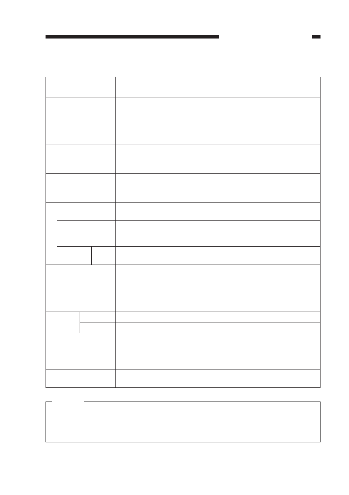
II. SPECIFICATIONS
A. Copier
1. Type
2. System
COPYRIGHT
©
1997 CANON INC. CANON NP6218 REV. 0 MAY 1997 PRINTED IN JAPAN (IMPRIME AU JAPON)
CHAPTER 1 GENERAL DESCRIPTION
1-2
Item
Body
Copyboard
Light source
Lens
Photosensitive
medium
Description
Desk top
Fixed
Fluorescent lamp
Zoom
OPC (ø30)
Item
Copying
Charging
Exposure
Copy density
adjustment
Development
Pick-up
Auto
Manual
Transfer
Separation
Cleaning
Fixing
Description
Indirect electrophotographic
Roller (direct charging)
Slit (moving light source)
Automatic (AE) or manual
Dry (toner projection)
1 cassette
Multifeeder
Roller
Curvature + static eliminator
Cleaning blade
Fixing (by plane-shaped heater; 1100 W max.)
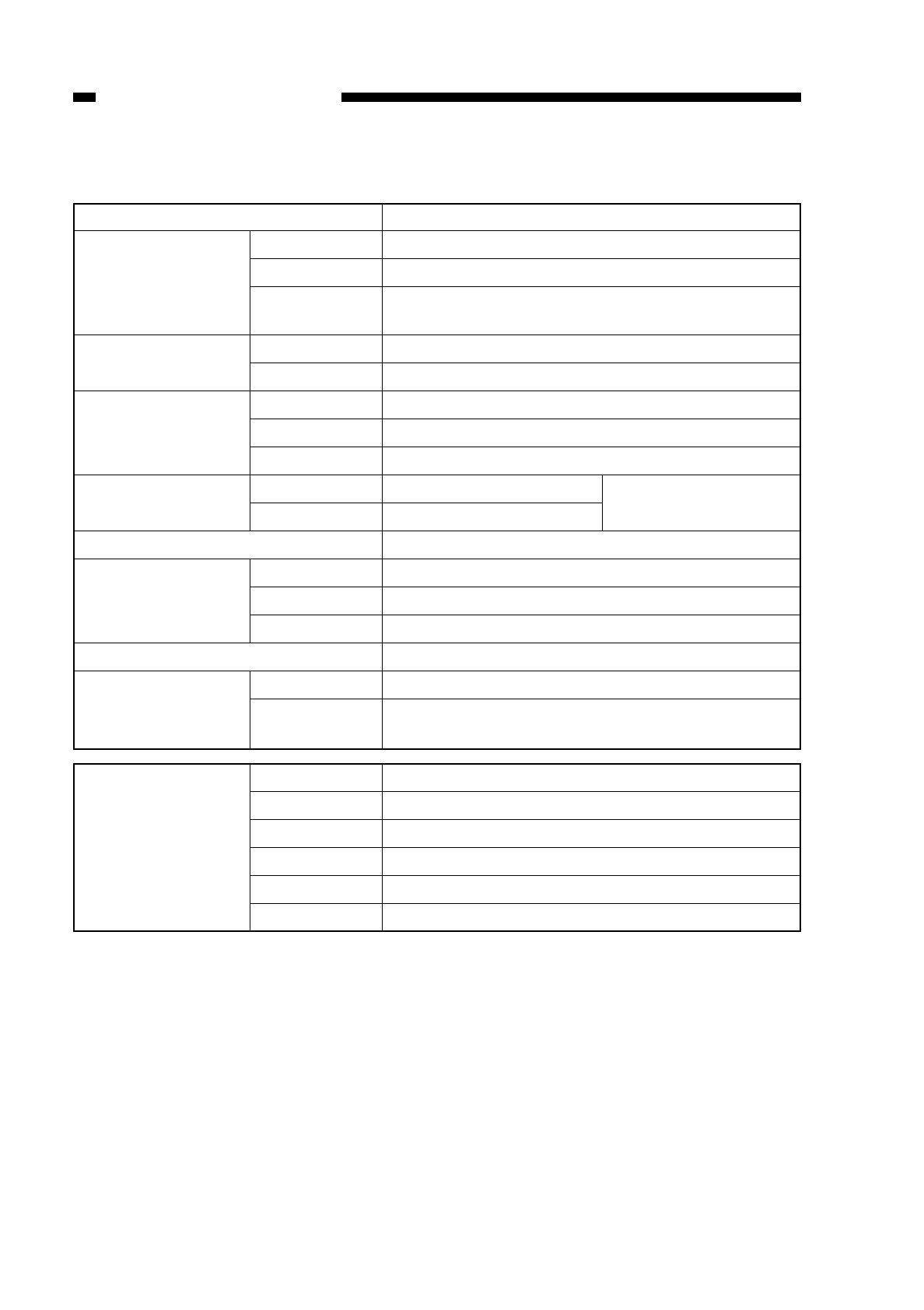
3. Features
Caution:
1. Use Canon-recommended paper.
2. Remove curling before feeding for a second time.
3. Fan out the transparencies before setting them on the multifeeder to prevent
adhesion.
COPYRIGHT
©
1997 CANON INC. CANON NP6218 REV. 0 MAY 1997 PRINTED IN JAPAN (IMPRIME AU JAPON)
CHAPTER 1 GENERAL DESCRIPTION
1-3
Item
Original type
Maximum original
size
Reproduction ratio
Wait time
First copy
Continuous copying
Copying speed
Copy size
Cassette
Manual
Two-sided/ Manual
overlay
Cassette
Multifeeder
Copy tray
Non-image One-sided
width Multi manual
Auto clear
Auto power-off
Option
Specification
Sheet, book, 3-D object (2 kg max.)
A3 (297 ×420 mm)/LDG (11" ×17")
Center reference
Direct, 2R2E (Table 1-201)
Zoom 49% to 204%
0 sec
8.2 sec or less (11.6 sec or less at power-on; A4, Direct, non-AE,
from cassette)
100 (max.; upper limit may be varied in service mode)
See Table 1-202.
Cassette: A3/11" ×17" to A5/STMT 3.94" ×5.88"
Manual: A3/11" ×17" to postcard (vertical)
Plain paper (64 to 80 g/m2), tracing paper (SM1), colored paper,
recycled paper (64 to 80 g/m2), ecology paper (80 g/m2)
Plain paper (64 to 80 g/m2), tracing paper (SM1, GNT80), colored
paper, recycled paper (64 to 80 g/m2), ecology paper (80 g/m2),
transparency, postcard, label sheet, thick paper (81 to 128 g/m2)
Plain paper (64 to 80 g/m2), colored paper, postcard, recycled paper
(64 to 880 g/m2), ecology paper (80 g/m2)
34 mm deep (approx.; about 250 sheets of 80 g/,m2paper),
clawless, front loading (center reference)
5 mm high (max.; about 50 sheets of 80 g/m2), clawless (center
reference)
100 sheets (approx.; A3 size, 80 g/m2)
2.0 ±1.0 mm (leading edge), 2.5 ±1.5 mm (left/right, trailing edge)
2.0 ±1.0 mm (leading edge), 3.5 ±1.5 mm (left/right, trailing edge)
Available (2 min standard; may be varied between 1 to 9 min in 1-
minute increments; may be disabled)
Available (5 min standard; may be varied in user mode to 2, 5, 10,
15, 30, 60, 120 min)
Cassette Feeding Module-B2, Cassette Feeding Module-A2, Control
Card IV N, Stapler Sorter B2/D1, MS-B1 ADF-E1
Copy paper
4. Others
Table 1-201 Standard Reproduction Ratios
Reproduction ratio DIRECT
REDUCE I
REDUCE II
ENLARGE I
ENLARGE II
ZOOM
COPYRIGHT
©
1997 CANON INC. CANON NP6218 REV. 0 MAY 1997 PRINTED IN JAPAN (IMPRIME AU JAPON)
CHAPTER 1 GENERAL DESCRIPTION
1-4
Item
Operating environment
Temperature
Humidity
Atmospheric
pressure
Power supply
230 V (50Hz)
Power consumption Maximum
Standby
Continuous
Noise Copying
Standby
Ozone (average over 8 hr)
Dimensions Width
Depth
Height
Weight
Consumables Copy paper
Cartridge
Specifications
7.5°C to 32.5°C/45.5°F to 90.5°F
5% RH to 85% RH
810.6 hPa to 1013.3 hPa (0.8 to 1 atm)
Serial numbers
UCDXXXXX
1.5 kW or less
97.2 kJ per hr (27 wh average; reference only)
2088 kJ (580 wh average; reference only)
49.7 dB or less (1 m front) Sound power level by
—ISO method
0.01 ppm or less (average); 0.02 ppm or less (max.)
585 mm/23.0 in
622 mm/24.5 in
345 mm/13.6 in
48 kg (approx.)
Keep wrapped to protect against humidity.
Avoid direct rays of the sun; keep at 40°C/104°F,
85% RH.
1: 1 (±0.5%)
1: 0.500
1: 0.707
1: 1.414
1: 2.000
49% to 204% (1% increments)
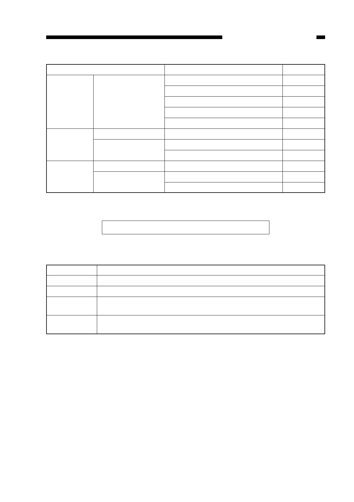
Table 1-202 Copying Speed
Specifications subject to change without notice.
B. Cassette Feeding Module-B2/Cassette Feeding Module-A2
Table 1-203
Copies/min
10
18
21
14
18
20
12
12
11
10
19
COPYRIGHT
©
1997 CANON INC. CANON NP6218 REV. 0 MAY 1997 PRINTED IN JAPAN (IMPRIME AU JAPON)
CHAPTER 1 GENERAL DESCRIPTION
1-5
Reproduction ratio
DIRECT 1: 1 (±0.5%)
REDUCE 1: 0.500 (+1.0%)
1: 0.707 (+1.0%)
ENLARGE 1: 2.000 (+1.0%)
1: 1.414 (+1.0%)
Copy size
A3 (297 ×420)
A4 (210 ×297)
A5 (148 ×210)
A4R (297 ×210)
A5R (210 ×148)
A3 →A5R
A3 →A4R
A4 →A5
A5R →A3
A4R →A3
A5 →A4
Copy paper
Cassette
Power supply
Dimensions
Weight
As per copier.
As per copier.
34 V DC, 24V, 5V (from copier)
Cassette Feeding Module-B2: 585W ×622D ×105H (mm) /23.0in x 24.5in x 8.3in
Cassette Feeding Module-A2: 585W ×622D ×210H (mm) /23.0in x 24.5in x 4.1in
Cassette Feeding Module-B2: 9kg
Cassette Feeding Module-A2:16kg
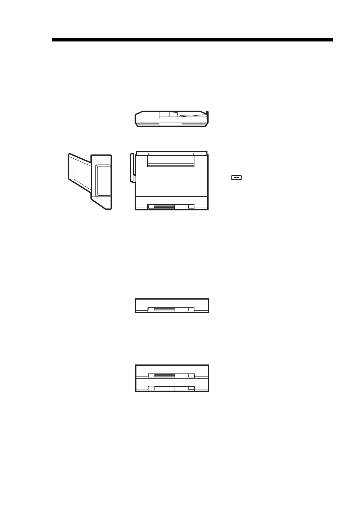
III. NAMES OF PARTS
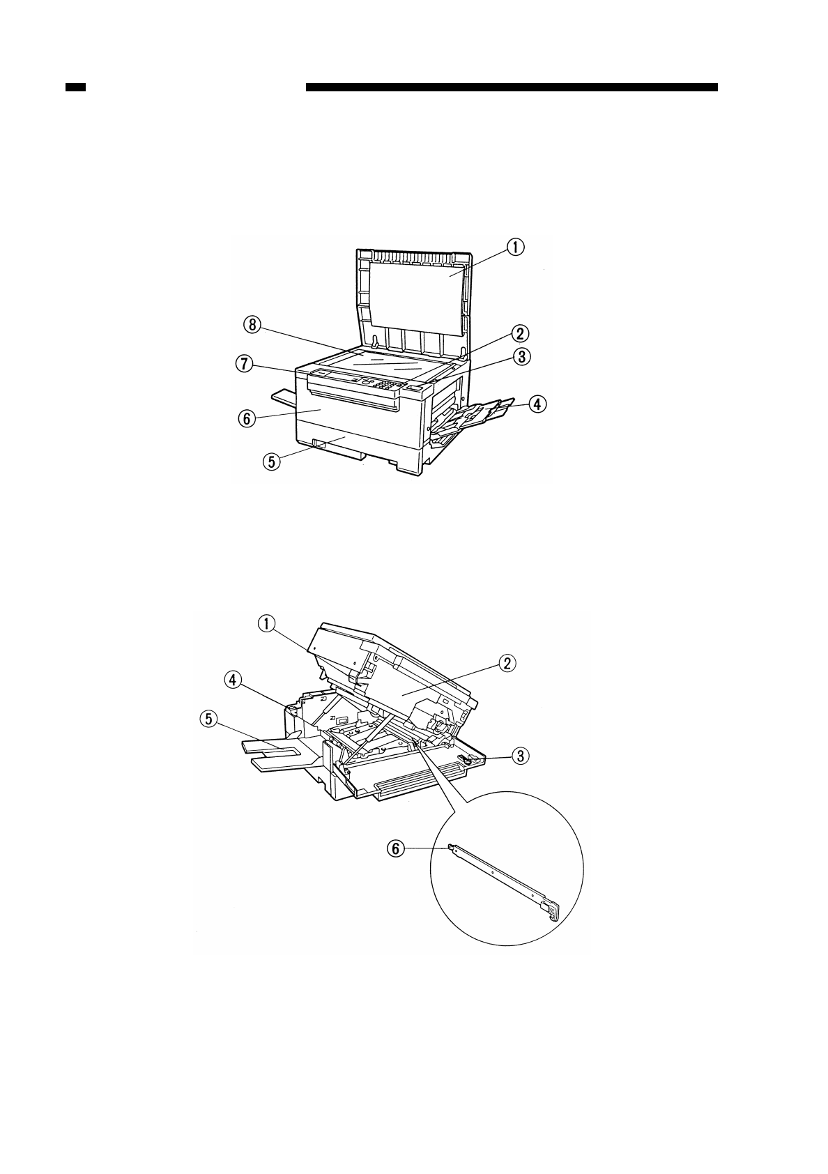
A. Exterior View
Figure 1-301
Figure 1-302
COPYRIGHT
©
1997 CANON INC. CANON NP6218 REV. 0 MAY 1997 PRINTED IN JAPAN (IMPRIME AU JAPON)
CHAPTER 1 GENERAL DESCRIPTION
1-6
qCopyboard cover
wPower switch
eClip tray
rMultifeeder
tCassette
yFront door
uControl panel
iCopyboard glass
qOpen/close lever
wCopy density correction knob
eStatic eliminator cleaner
rHeater switch
tCopy tray
yStatic eliminator
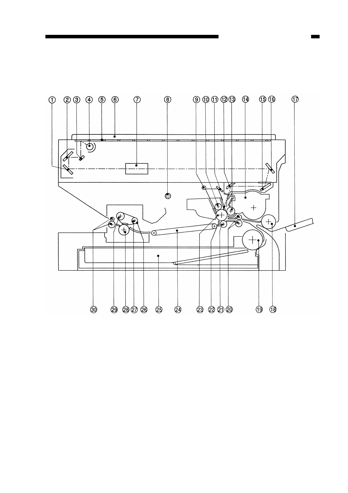
B. Cross Section
1. Body
Figure 1-303
COPYRIGHT
©
1997 CANON INC. CANON NP6218 REV. 0 MAY 1997 PRINTED IN JAPAN (IMPRIME AU JAPON)
CHAPTER 1 GENERAL DESCRIPTION
1-7
qNo. 3 mirror
wNo. 2 mirror
eNo. 1 mirror
rScanning lamp
tCopyboard glass
yCopyboard cover
uLens
iExhaust fan
oPre-exposure lamp
!0 Primary charging roller
!1 Reflecting plate
!2 No. 6 mirror
!3 Developing cylinder
!4 Developing assembly
!5 No. 5 mirror
!6 No. 4 mirror
!7 Multifeeder tray
!8
Multifeeder pick-up roller
!9 Cassette pick-up roller
@0 Registration roller
@1 Transfer roller
@2
Separation static eliminator
@3 Photosensitive drum
@4 Feeding assembly
@5 Cassette
@6 Fixing film
@7 Film tension roller
@8 Film pressure roller
@9 Film drive roller
#0 Delivery roller
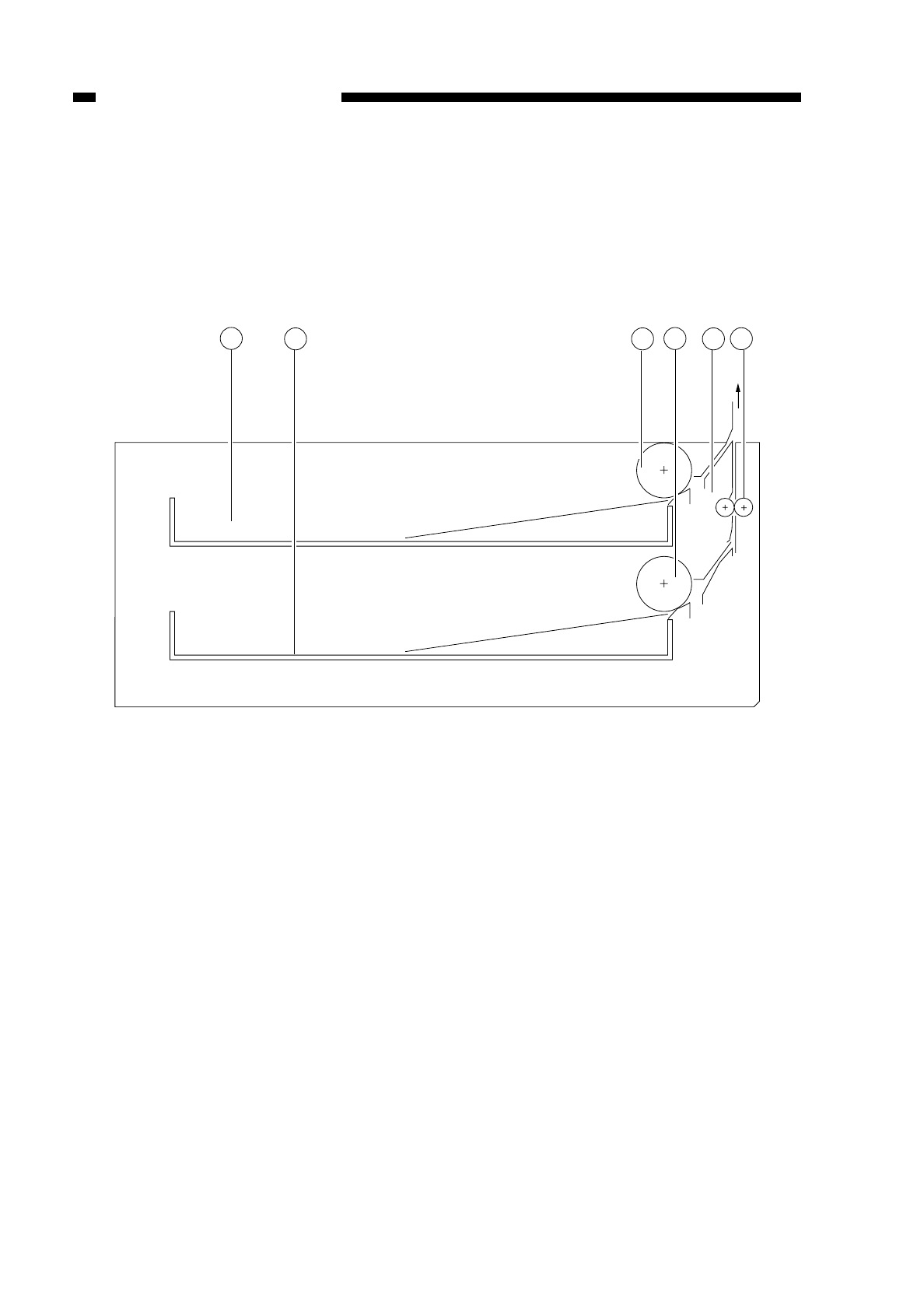
2. Cassette Feeding Module-A2
Figure 1-304
COPYRIGHT
©
1997 CANON INC. CANON NP6218 REV. 0 MAY 1997 PRINTED IN JAPAN (IMPRIME AU JAPON)
CHAPTER 1 GENERAL DESCRIPTION
1-8
qCassette 2
wCassette 3
eCassette 2 pick-up roller
rCassette 3 pick-up roller
tDrive roller
yFeeding roller
6
4
2
13 5
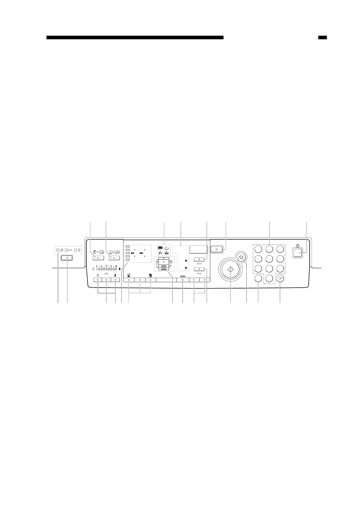
IV. OPERATION
A. Control Panel
Figure 1-401
COPYRIGHT
©
1997 CANON INC. CANON NP6218 REV. 0 MAY 1997 PRINTED IN JAPAN (IMPRIME AU JAPON)
CHAPTER 1 GENERAL DESCRIPTION
1-9
123
456
789
C 0
Max 200%
A4
1:1
Min 50%
A3 A5 A4
A3 A4 A4 A5
A
1:1
123
Autom. Paper
A3
A4
A4
R
A5
A5
R
A4
R
%
Autom. Zoom
Zoom
+–
qw er t y u i
o!1!2 !0@1@2 !3!4!5!6!7!8!9@0
qImage Compose key
wPage Separate key
eWarning indicator
rDisplay
t% key
yReset key
uKeypad
iPower switch
oInterrupt key
!0 Clear key
!1 Stop key
!2 Start key
!3 Auto Ratio key
!4 Zoom key
!5 Paper Select key
!6 Cassette/Jam indicator
!7 Direct key
!8 Reduce/Enlarge key
!9 Copy density key
@0 AE key
@1 Sorter key
@2 Sorter indicator

B. Operation Mode
Table 1-401
COPYRIGHT
©
1997 CANON INC. CANON NP6218 REV. 0 MAY 1997 PRINTED IN JAPAN (IMPRIME AU JAPON)
CHAPTER 1 GENERAL DESCRIPTION
1-10
Mode
Image Composition
mode
Page Separation
mode
Interrupt mode
Auto Ratio mode
AE mode
Sort/staple
sort/group mode
Description
Press to set/reset image composition mode.
Press to set/reset page separation mode.
Press to interrupt an ongoing copying
session.
Press it to set/reset auto ratio mode.
Press to set/re-set AE mode or user mode.
Press it to select/reset sort, staple sort, or
group mode.
Remarks
Only when an ADF
(accessory) is installed.
Only when an ADF
(accessory) is installed.
Only when an sorter
(accessory) is installed.
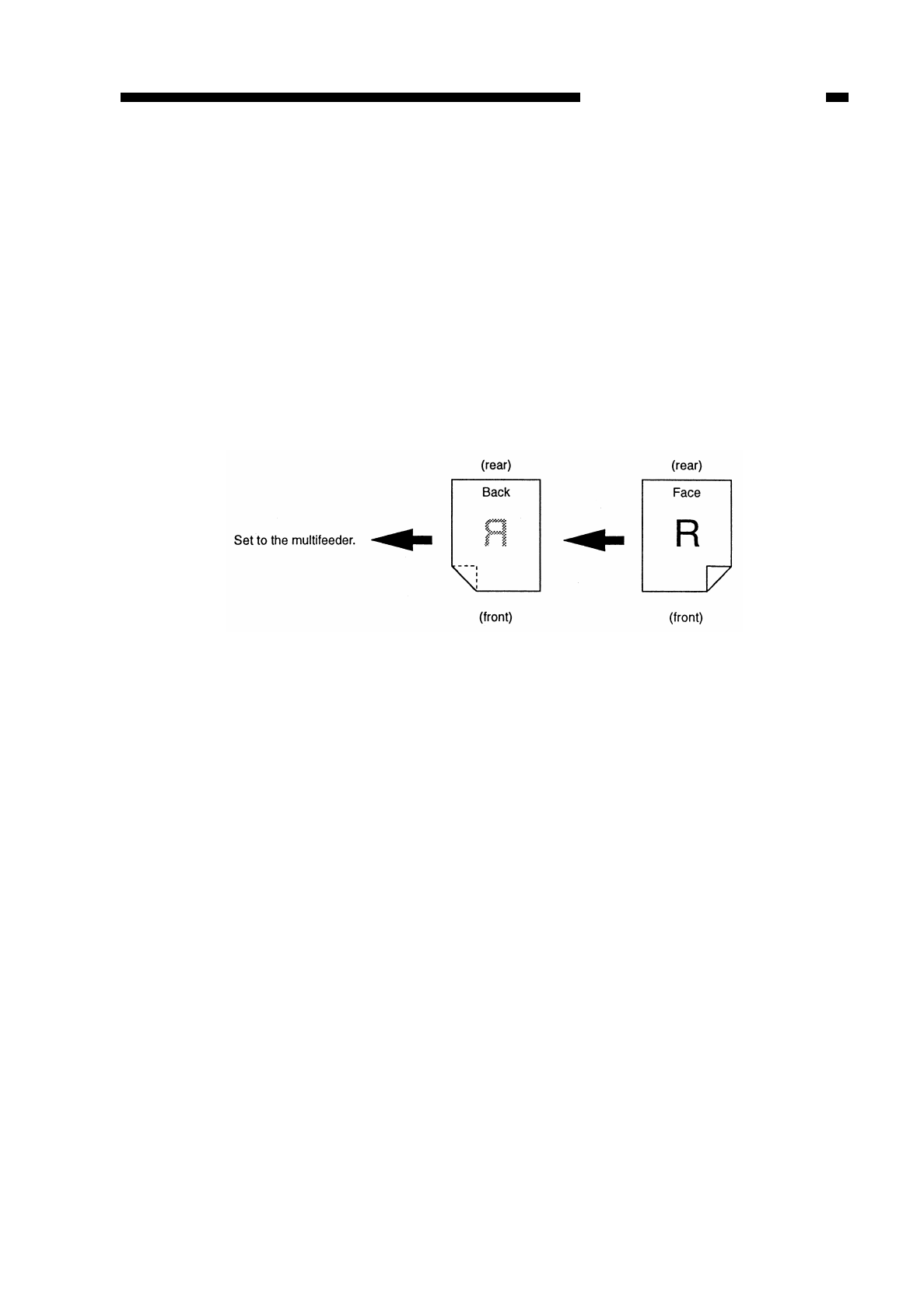
C. Making Two-Sided/Overlay Copies (manual)
You can make two-sided or overlay copies by manually feeding paper. You must,
however, keep the following in mind when making such copies:
qBe sure to orient the paper the same way for both sides when turning it over.
wMake sure that the paper has not absorbed moisture.
eMake sure that the paper has no curling.
rAfter copying on the first side, sufficiently cool the paper; then, correct any curling
before feeding it for a second time.
tUse paper of 60 to 128 g/m2.
yCorrect any curling on postcards or thick paper (128 g/m2) before copying on the
second side.
Figure 1-405
COPYRIGHT
©
1997 CANON INC. CANON NP6218 REV. 0 MAY 1997 PRINTED IN JAPAN (IMPRIME AU JAPON)
CHAPTER 1 GENERAL DESCRIPTION
1-11

D. User Mode
1. Outline
The copier provides user mode, which allows the user to change various settings or
to make various adjustments on his/her own; see Table 1-402.
Table 1-402
Display
COPYRIGHT
©
1997 CANON INC. CANON NP6218 REV. 0 MAY 1997 PRINTED IN JAPAN (IMPRIME AU JAPON)
CHAPTER 1 GENERAL DESCRIPTION
Menu No.
1
2
3
5
6
9
0
1-12
Function
Changing the auto
clear time
Changing the auto
power-off time
Fine adjusting
(zoom)
Turning on/off
auto sort/non-sort
(with ADF* and
sorter* installed)
*Accessory
Cleaning the feeder
(with ADF* installed)
Option
Selecting a densi-
ty adjustment
method for
standard mode
Initializing user
mode
Description
You may set the auto clear time
between 1 and 9 min in 1-min
increments. Setting it to ‘0’
disables the function.
You can set the auto power-off
time to either 2, 5, 10, 15, 30, 60,
or 120 min.
You can correct a slight discrep-
ancy between original and copy
sizes (direct); enlarge in X direc-
tion and reduce in Y direction
independent of each other.
You may specify whether to
evecute auto sort/non-sort.
Use it to clean the pick-up
assembly of the ADF.
You can specify either AE or
manual for density adjustment for
standard mode.
You can return settings changed
in user mode to initial settings.
Default settings
2 min
5 min
± 0%
On
AE
2. Common Operations
a. Keys to Use in User Mode
• Clear Key
Use it to return to the previous step; or, use it to clear a setting entered by mistake
when making mode settings.
• Start Key
Use it to accept a selected item when making user mode settings.
• AE Key
Use it to return to copy mode when making user mode settings.
b. Operation
1) Hold down the AE key for about 4 sec or more.
• This will turn on the display, indicating “ ”.
2) Enter the menu number of each function using the keypad.
3) Press the Start key.
• The current setting of the respective function appears.
4) Enter a new setting using the appropriate key.
5) Press the start key.
• The copy count/ratio indictor turns on to indicate the user mode being changed.
• The setting of the respective user mode is changed.
6) Press the AE key.
• The copier returns to standby state.
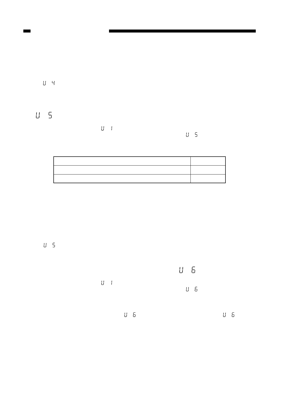
3. Changing the Auto Clear Time ( )
1) Hold down the AE key for 4 sec or more.
• “ ” appears on the display.
2) Press the Start key.
• The display indicates the current setting (if initial, indicates ‘1-2’).
3) Enter a desired setting using the keypad.
• The display indicates the new setting (if 5 min, indicates ‘1-5’).
4) Press the Start key. “ ”
5) Press the AE key.
• The copier returns to standby state.
4. Changing the Auto Power-Off Time ( )
1) Hold down the AE key for 4 sec or more.
• “ ” appears on the display.
2) Enter ‘2’ using the keypad so that the display indicates “ ”.
3) Press the Start key.
• The display indicates the current setting (if initial, indicates ‘2-2’).
4) Enter a desired setting using the keypad.
COPYRIGHT
©
1997 CANON INC. CANON NP6218 REV. 0 MAY 1997 PRINTED IN JAPAN (IMPRIME AU JAPON)
CHAPTER 1 GENERAL DESCRIPTION
1-13
Table 1-403
• The display indicates the new setting (if 10 min, indicates ‘2-3’).
5) Press the Start key.
• The auto power-off time is changed, and the display returns to “ ”.
6) Press the AE key.
• The copier returns to standby state.
Reference:
If you want to disable the auto power-off function, use service mode (See p. 10-109.).
5. Zoom Fine-Adjustment ( )
1) Hold down the AE key for 4 sec or more.
• The display indicates “ ”.
2) Enter ‘3’ using the keypad so that the display indicates “ ”.
3) Press the Start key.
• The display indicates ‘3-1’ suggesting the direction of adjustment.
Table 1-404
Further, the copy density indicator shows the current setting. (See Figure 1-406.)
4) Press the copy density key to adjust the reproduction ratio in X direction. (See Figure
1-406.)
5) Press the Start key.
• The reproduction ratio in X direction is fine-adjusted, and the display indicates ‘3-
2’.
Further, the copy density indicator shows the current setting. (See Figure 1-406.)
6) Press the Density key to adjust the reproduction ratio in Y direction. (See Figure 1-
406.)
COPYRIGHT
©
1997 CANON INC. CANON NP6218 REV. 0 MAY 1997 PRINTED IN JAPAN (IMPRIME AU JAPON)
CHAPTER 1 GENERAL DESCRIPTION
1-14
Auto power-off time (min)
2
5
10
15
30
60
120
Settings
2-1
2-2
2-3
2-4
2-5
2-6
2-7
Direction of adjustment
X direction (horizontal)
Y direction (vertical)
Display
3-1
3-2
7) Press the Start key.
• The zoom reproduction is fine-adjusted, and the display returns to “ ”.
8) Press the AE key.
• The copier returns to standby state.
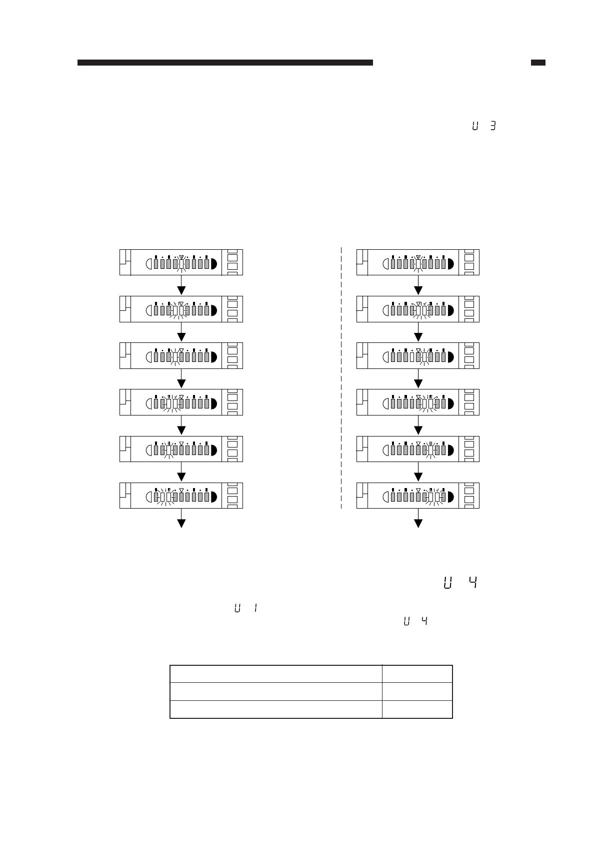
The fine-adjustment reproduction ratios as shown in the copy density display are as
follows:
■Zoom Fine-Adjustment (Reduce) ■Zoom Fine-Adjustment (Enlarge)
Press the Lighter key. Press the Darker key.
Figure 1-402
6. Turning On and Off the Auto Cassette Change Mechanism ( )
1) Hold down the AE key for 4 sec or more.
• The display indicates “ ”.
2) Enter rusing the keypad so that the display indicates “ ”.
3) Press the Start key.
• The display indicates the current setting (if initial setting, ‘4-1’).
Table 1-405
COPYRIGHT
©
1997 CANON INC. CANON NP6218 REV. 0 MAY 1997 PRINTED IN JAPAN (IMPRIME AU JAPON)
CHAPTER 1 GENERAL DESCRIPTION
1-15
Initial setting
(±0%)
-0.2%
-0.4%
-0.6%
-0.8%
-1.0%
Initial setting
(±0%)
+0.2%
+0.4%
+0.6%
+0.8%
+1.0%
State of auto cassette change function
On
Off
Settings
4-1
4-0
4) Enter qor pusing the keypad to specify ‘On’ or ‘Off’.
• The display indicates the new setting (if Off, ‘4-0’.)
5) Press the Start key.
• The auto cassette change function is turned on or off, and the display returns to
“ ”.
6) Press the AE key.
• The copier returns to standby state.
7. Turning On/Off the Auto Sort/Non-Sort (with ADF and sorter installed—option)
( )
1) Hold down the AE key for 4 sec or more.
• The display indicates “ ”.
2) Enter tusing the keypad so that the display indicates “ ”.
3) Press the Start key.
The display indicates the current setting (if initial settings, ‘5-1’).
Table 1-406
4) Enter qor pusing the keypad to select On or Off.
• The display indicates the new setting (if Off, ‘5-0’).
5) Press the Start key.
• The auto cassette change will be either On or Off, and the display returns to
“ ”.
6) Press the AE key.
• The copier returns to standby state.
8. Cleaning the Feeder (with ADF installed—option) ( )
1) Hold down the AE key for 4 sec or more.
• The display indicates “ ”.
2) Enter yusing the keypad so that the display indicates “ ”.
3) Place about 10 sheets of blank copy paper (white) on the ADF’s original tray.
4) Press the Start key.
• Feeder cleaning starts; to stop, press the Stop key.
During the cleaning operation, “ ” on the display flashes; then, “ ” stops
flashing and remains on.
5) Press the AE key.
• The copier returns to standby state.
COPYRIGHT
©
1997 CANON INC. CANON NP6218 REV. 0 MAY 1997 PRINTED IN JAPAN (IMPRIME AU JAPON)
CHAPTER 1 GENERAL DESCRIPTION
1-16
Turning on/off the auto cassette change mechanism
On
Off
Settings
5-1
5-0
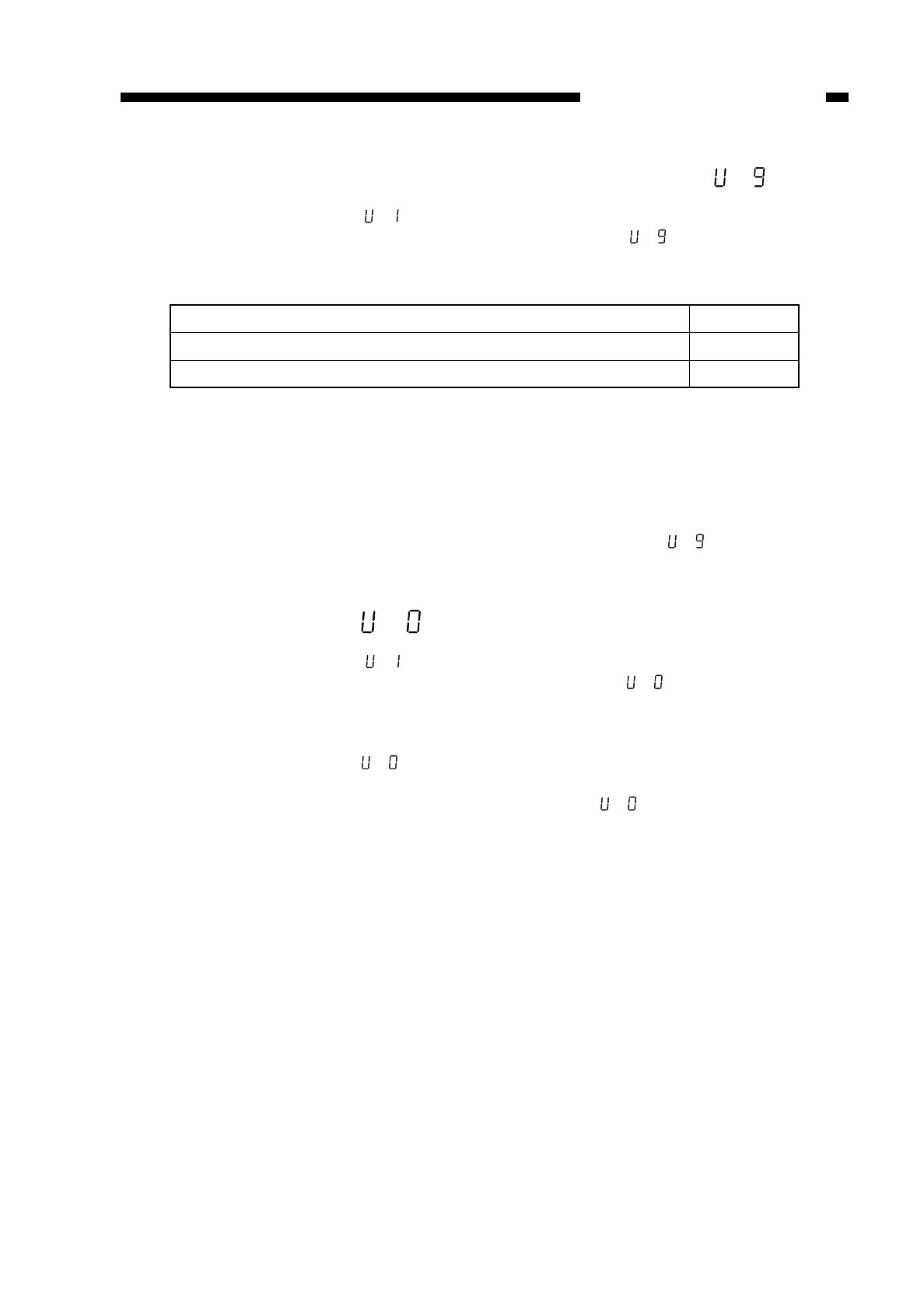
9. Selecting the Density Adjustment Method for Standard Mode ( )
1) Hold down the AE key for 4 sec or more.
• The display indicates “ ”.
2) Enter ousing the keypad so that the display indicates “ ”.
3) Press the Start key.
• The display indicates ‘9-1’.
Table 1-407
4) Enter qor pusing the keypad to select AE or manual so that the display indicates
the new specification (if manual, indicates ‘9-0’).
5) Press the Start key.
• The new specification is stored, and the display returns to “ ”.
6) Press the AE key.
• The copier returns to standby state.
10.Initializing User Mode ( )
1) Hold down the AE key for 4 sec or more.
• The display indicates “ ”.
2) Enter pusing the keypad so that the display indicates “ ”.
3) Press the Start key.
• The display indicates ‘0-1’.
4) Enter pusing the keypad.
• The display indicates “ ”.
5) Press the Start key.
• User mode is initialized, and the display returns to “ ”.
6) Press the AE key.
• The copier returns to standby state.
COPYRIGHT
©
1997 CANON INC. CANON NP6218 REV. 0 MAY 1997 PRINTED IN JAPAN (IMPRIME AU JAPON)
CHAPTER 1 GENERAL DESCRIPTION
1-17
Selecting the density adjustment method for standard mode
AE (automatic)
Manual
Settings
9-1
9-0
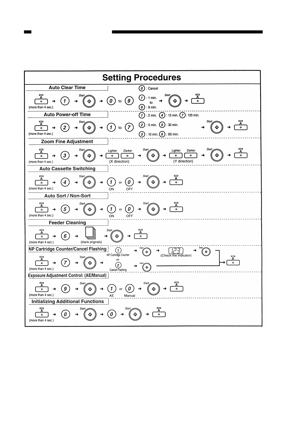
11.Quick Guide to User Mode
Table 1-408
COPYRIGHT
©
1997 CANON INC. CANON NP6218 REV. 0 MAY 1997 PRINTED IN JAPAN (IMPRIME AU JAPON)
CHAPTER 1 GENERAL DESCRIPTION
1-18

COPYRIGHT
©
1997 CANON INC. CANON NP6218 REV. 0 MAY 1997 PRINTED IN JAPAN (IMPRIME AU JAPON)
CHAPTER 1 GENERAL DESCRIPTION
1-19
E. Handling the Toner Bottle
Instruct the user to dispose of any empty toner bottle as nonflamable material.
Caution:
Do not dispose of the toner bottle into fire.
It may explode.
V. WARNINGS AND ACTIONS
• Handling the Toner Bottle
Instruct the user to dispose of any empty toner bottle as nonflammable material.
Caution:
Do NOT throw the cartridges into fire; it can burst or explode.
VI. ROUTINE MAINTENANCE BY THE USER
Make sure that the user cleans the following parts once a week:
qCopyboard Glass
Use a cloth moistened with water or mild detergent solution; then, dry wipe it.
wCopyboard Cover
Use a cloth moistened with water or mild detergent solution; then, dry wipe it.
eStatic Eliminator
If separation jams occur frequently, use the special brush (accessory) to clean it; the
eliminator need not be cleaned as often as once a week.
!
!
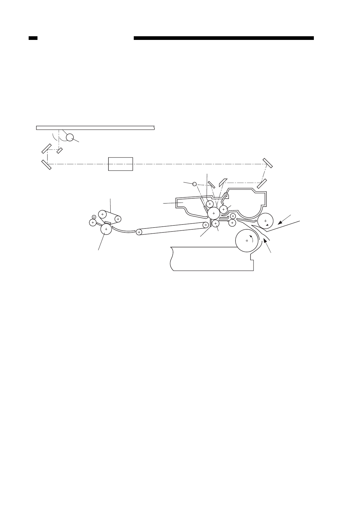
VII. IMAGE FORMATION
A. Outline
Figure 1-601
The copier uses an electrostatographic method to produce images and is
constructed as shown in Figure 1-601.
It is equipped with an automatic control mechanism to ensure stable reproduction of
high-quality images.
COPYRIGHT
©
1997 CANON INC. CANON NP6218 REV. 0 MAY 1997 PRINTED IN JAPAN (IMPRIME AU JAPON)
CHAPTER 1 GENERAL DESCRIPTION
1-20
Copyboard glass
Scanning lamp
Lens
Pre-exposure lamp
Primary corona roller
Developing cylinder
Static eliminator
Transfer roller
Fixing film
Pressure roller
Cleaning assembly Pick-up
(multifeeder)
Pick-up
(cassette)
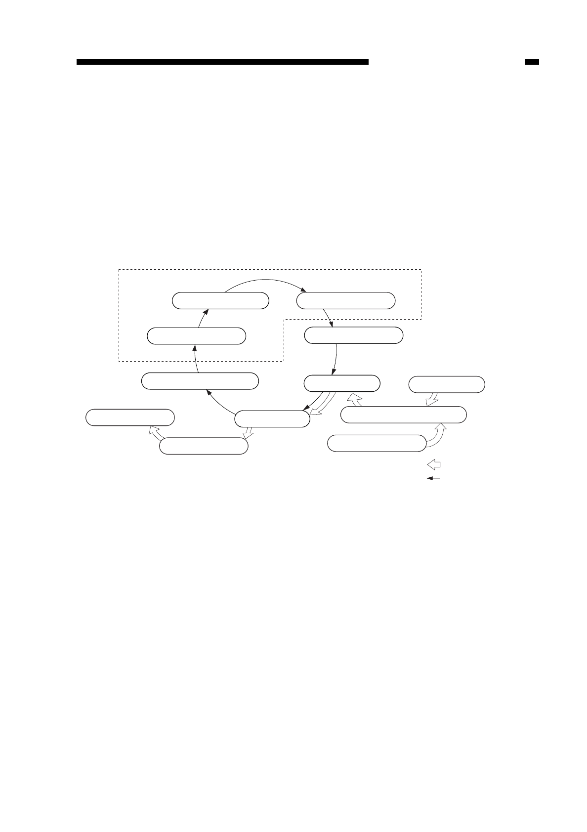
The NP6218 generates images in the following eight steps.
Step 1. Pre-exposure
Step 2. Primary charging
Step 3. Image exposure
Step 4. Development (AC + positive DC)
Step 5. Transfer (positive DC)
Step 6. Seperation (AC + positive DC)
Step 7. Fixing
Step 8. Drum cleaning
Figure 1-602
COPYRIGHT
©
1997 CANON INC. CANON NP6218 REV. 0 MAY 1997 PRINTED IN JAPAN (IMPRIME AU JAPON)
CHAPTER 1 GENERAL DESCRIPTION
1-21
Static latent image formation block
2. Primary charging
1. Pre-exposure
8. Drum Cleaning 5. Transfer
3. Image exposure
4. Development
Manual feeding
Registration
Cassette
flow of copy paper
rotation of drum
6. Separation
Delivery
7. Fixing

COPYRIGHT
©
1997 CANON INC. CANON NP6218 REV. 0 MAY. 1997 PRINTED IN JAPAN (IMPRIME AU JAPON)
CHAPTER 1 GENERAL DESCRIPTION
1-22

COPYRIGHT
©
1997 CANON INC. CANON NP6218 REV. 0 MAY 1997 PRINTED IN JAPAN (IMPRIME AU JAPON)
CHAPTER 2
BASIC OPERATION
I. BASIC CONSTRUCTION...................2-1
A. Functional Construction.................2-1
B. Outline of the Electrical Circuitry...2-2
C. Basic Sequence of Operations
(2 copies continuous, AE) .............2-3
D. Main Motor Control Circuit.............2-4
E. Inputs to the DC Controller PCB ...2-5
F. Outputs from the DC Controller
PCB ...............................................2-8
G. Inputs to and Outputs from the
1-Cassette Unit Driver PCB...........2-11
H. Inputs to and Outputs from the
2-Cassette Unit Driver PCB...........2-12
This chapter provides outlines of the copier’s various operational workings. (Note that a single
rotation of the drum takes about 0.29 sec.)
I. BASIC CONSTRUCTION
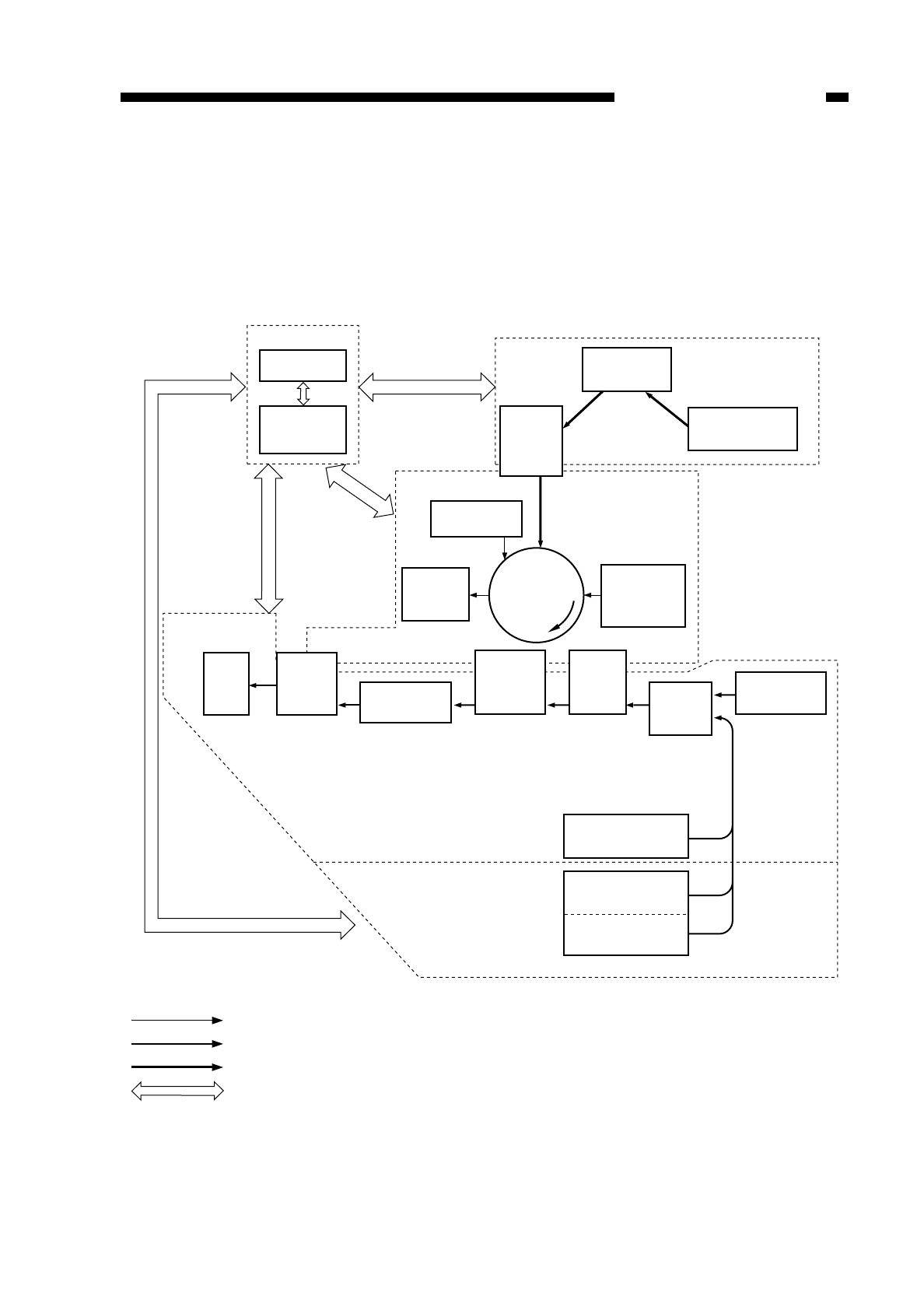
A. Functional Construction
The copier may be divided into four blocks; namely, the pick-up/feeding system,
exposure system, image formation system, and control system.
Figure 2-101
COPYRIGHT
©
1997 CANON INC. CANON NP6218 REV. 0 MAY 1997 PRINTED IN JAPAN (IMPRIME AU JAPON)
CHAPTER 2 BASIC OPERATION
2-1
Control system
Control circuit
assembly
Control
assembly
Tray Fixing
assembly Feeding
assembly
Drum
cleaning
assembly
Primary
charging
Optical
path
Photosensitive
drum
Separation Transfer
Pick-up/feeding
system 1
Pick-up/feeding
system 2
Copyboard Exposure system
Scaning lamp
assembly
Image formation
system
Developing
assembly
Pick-up
control
assembly
Cassette Feeding
module B2
Cassette Feeding
module A2
Manual feed
assembly
Flow of high voltage/toner
Flow of paper
Flow of light
Flow of electrical signals
Cassette 1
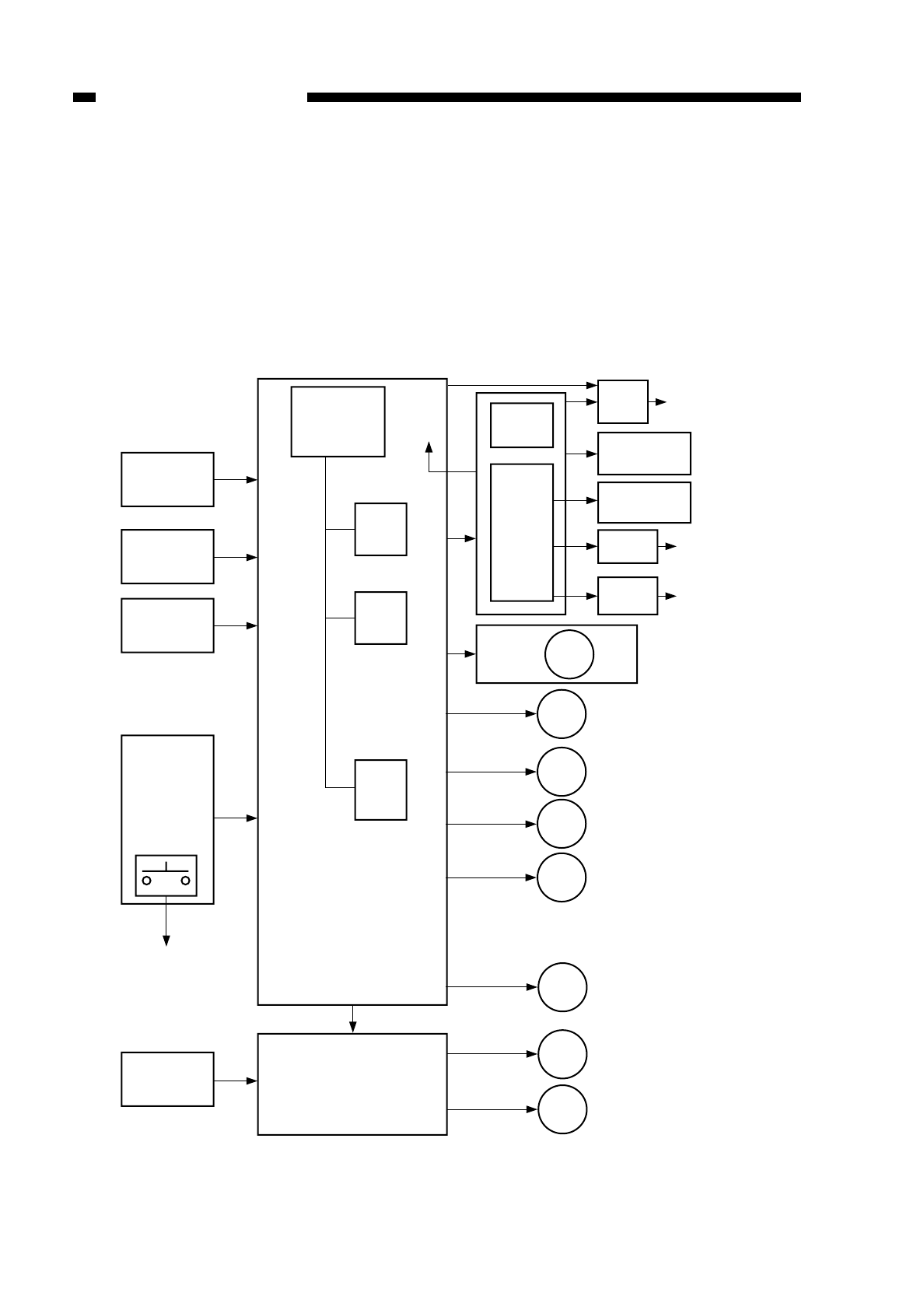
B. Outline of the Electrical Circuitry
The copier’s principal electrical mechanisms are controlled by the microprocessor on
the DC controller PCB. The microprocessor reads the input signals from the sensors and
operation keys according to the stored program and generates signals used to drive such
loads as motors, solenoids, and lamps.
The microprocessor is capable of reading both digital and analog signals because of
its built-in A/D converter.
Figure 2-102
COPYRIGHT
©
1997 CANON INC. CANON NP6218 REV. 0 MAY 1997 PRINTED IN JAPAN (IMPRIME AU JAPON)
CHAPTER 2 BASIC OPERATION
2-2
Sensor
AE sensor PCB
Main thermistor
Sub thermistor
Control panel
Power switch
Control card (accessory)
Sensor
DC controller PCB
Cassette Driver PCB
(accessory)
Composite power supply
High-
voltage
circuit
ADF (accessory)
Sorter (accessory)
Scanning lamp
heater switch
Options
power
supply
Toner level
detection PCB
Bias PCB Developing
cylinder
Transfer current
Static eliminator
Primary crrent
Main motor
Pre-exposure lamp
Motor
Scanning motor
Lens motor
Fixing film moor
Fan Heat exhaust fan
Change solenoid
Multifeeder holding plate
solenoid
Blank shutter solenoid
Primary charging roller
Creaning solenoid
Transfer charging roller
reversting solenoid
Registration clutch
Delivery clutch
Multifeeder pick-up clutch
Motor Cassette unit motor
Cassette pick-up clutch
CL
CL
SL
LA
M1
HV
CPU
Q301
CPU
Q305
ROM
Q307
RAM
Q314
(for IPC
communi-
cation)
+5V
+24V
+34V
(accessory)
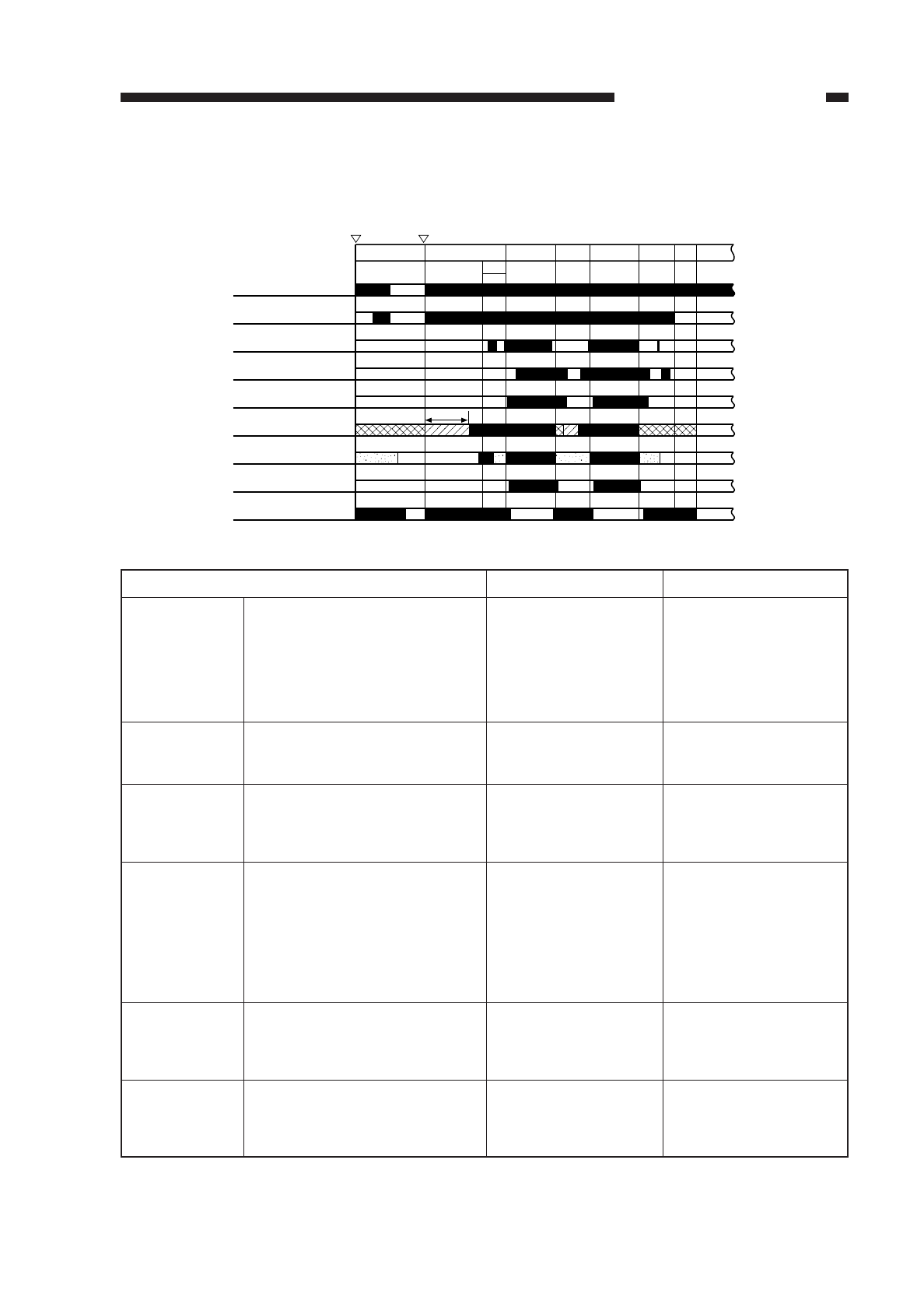
C. Basic Sequence of Operations (2 copies continuous, AE)
Figure 2-103
Table 2-101
COPYRIGHT
©
1997 CANON INC. CANON NP6218 REV. 0 MAY 1997 PRINTED IN JAPAN (IMPRIME AU JAPON)
CHAPTER 2 BASIC OPERATION
2-3
STBY INTR SCFW
Power switch
ON Copy Start key
ON
AER
Main motor (M1)
Fixing heater
Primary charging bias
Transfer bias
Static eliminator bias
Scanning lamp
Scanner
Developing AC bias
Developing DC bias
SCRV SCFW SCRV
LSTR
STBY
1.5sec
STBY (standby)
INTR
(initial rotation)
AER
(AE rotation)
SCFW
(scanner forward)
SCRV
(scanner reverse)
LSTR
(last rotation)
• Between when LSTR is over and
when the Copy Start key is
pressed or the Power switch is
pressed.
• Between when the Power switch
has been pressed and when the
Copy Start key is pressed.
For at least 1 sec after the Copy
Start key has been pressed.
While the scanner is moving for-
ward.
• The distance of forward travel
varies depending on the cassette
size and reproduction ratio.
• The distance of reverse travel
varies depending on the selected
reproduction ratio.
While the scanner is moving in
reverse.
Between when SCRV is over and
when the copy paper moves past the
delivery sensor.
Until the Copy Start key
or another operation key
is pressed.
The drum sensitivity is
stabilized in preparation
for a copy run.
The scanner is moved
about 65 mm forward and
in reverse to measure the
density of the original.
The scanning lamp illumi-
nates the original, and the
reflected optical image is
projected on the photo-
sensitive drum through
mirrors and lenses.
The scanner is returned
to the home position in
preparation for the next
copy run.
The surface of the photo-
sensitive drum is cleaned
using static electricity as
post treatment.
• Upon completion of
LSTR, the indications on
the control panel return
to indications for stan-
dard mode after 2 min.
AE mode only.
The registration signal is
generated to move the
copy paper to the transfer
assembly.
The last copy is
discharged.
Description RemarksPeriod
D. Main Motor Control Circuit
1. Outline
Figure 2-104 shows the circuit used to control the main motor (M1); the circuit has
the following functions:
qturns on and off the main motor.
wcontrols the main motor to a specific rotation speed.
The main motor (M1) is a DC motor that has a built-in clock pulse generator. When
the motor rotates, it generates clock pulse signals (MMCLK*) according to the revolution
of the motor. The speed control circuit matches the phases of the frequency of these
clock pulses and that of the reference signals to control the main motor (M1) to a specific
revolution speed.
2. Mechanism
When the main motor drive signal (MMD) from the DC controller circuit goes ‘1’, the
drive circuit of the motor driver turns on, thereby rotating the main motor (M1) at a
constant speed.
While the main motor is rotating at a specific speed, the motor driver PCB keeps
sending the specific speed state signal=0 (MLOCK*) to the DC controller PCB. If, for
some reason, an irregularity occurs in the rotation of the main motor, the MLOCK* signal
goes ‘1’.
If the main motor drive signal (MMD) remains ‘1’ and the MLOCK*=0 remains
unchanged for about 1 sec, the DC controller identifies a main motor error and stops the
main motor and, at the same time, indicates ‘E010’.
Figure 2-104
COPYRIGHT
©
1997 CANON INC. CANON NP6218 REV. 0 MAY 1997 PRINTED IN JAPAN (IMPRIME AU JAPON)
CHAPTER 2 BASIC OPERATION
2-4
J 501
- 1
- 2
J 502
- 2
J 303
- 3
J 502
- 1
J 303
- 4
+34V
J 206
MMD
MLOCK*
MMCLK
M1
DC controller
PCB
Phase control
circuit
Reference signal
Drive circuit Clock pulse generator
Drive
current
Main motor
Hall IC output
Main motor driver PCB
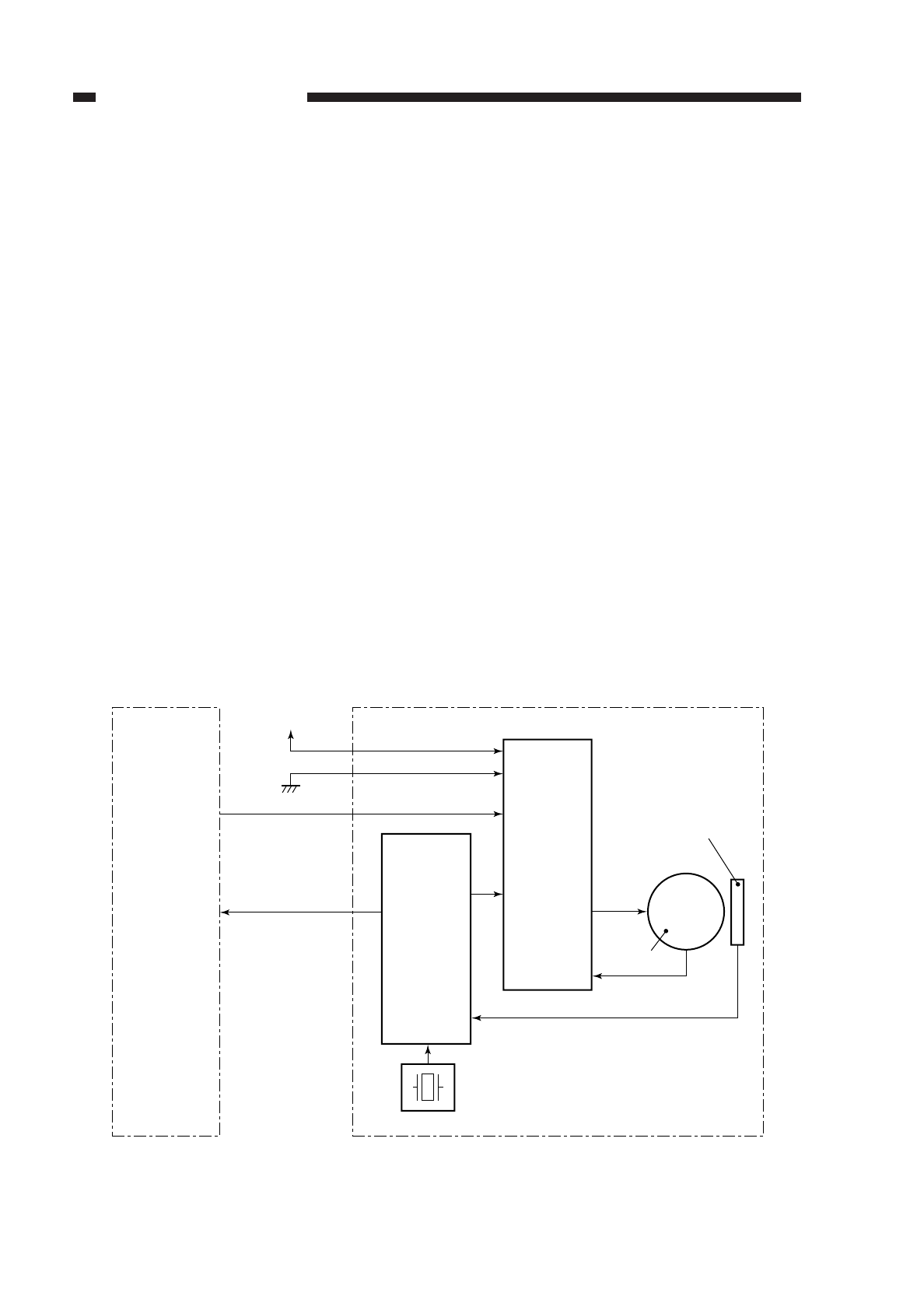
E. Inputs to the DC Controller PCB
1. Inputs to the DC Controller PCB (1/3)
Figure 2-105
COPYRIGHT
©
1997 CANON INC. CANON NP6218 REV. 0 MAY 1997 PRINTED IN JAPAN (IMPRIME AU JAPON)
CHAPTER 2 BASIC OPERATION
2-5
5V
PS 1
Registration
sensor
5V
J307
-3
-2
-1
PS 2 LHP When lens detects home position sensor, '1'.
(when light-blocking plate is at PS2, '1')
Lens home position
sensor
5V
J315
-3
-2
-1
PS 3 BSHP When blank home position sensor detects
the blank shutter, '1'.
(when light-blocking plate is at PS3, '1')
Blank shutter home
position sensor
5V
J313
-7
-9
-8 CPD* When paper is present in multifeeder, '0'.
(when light-blocking plate is not at PS4, '0')
PS 4
Cassette paper
sensor
5V
J313
-1
-3
-2 MFPD* When paper is present in cassette, '0'.
(when light-blocking plate is not at PS5, '0')
PS 5
Multifeeder paper
sensor
5V
J314
-3
-2
-1 RPD
PS 6
J314
-4
-6
-5
FFD When PS9 detects film, '0'.
(when light-blocking plate is at PS9, '1')
PS 7
Fixing film sensor
J304
-13
-12
-11
PS 9
Separation
sensor
DC controller PCB
5V
5V
RDOP* When right door is opened, '0'.
(when light-blocking plate is not at PS10, '0')
Right door open/
closed sensor
J306
-13
-15
-14
PS 10
5V
DPD* When PS8 does not detect paper, '0'.
(when light-blocking plate is not at PS8, '0')
Delivery sensor
J312
-3
-2
-1
PS 8
5V
J311
-3
-2
-1 SCHP When scanner is at home position, '1'.
(when light-blocking plate is at PS1, '1')
Scanner home
position sensor
When PS6 detects paper, '1'.
(when light-blocking-plate is at PS6, '1')
SPD* When PS7 detects paper, '0'.
(when light-blocking plate is not at PS 7, '0')
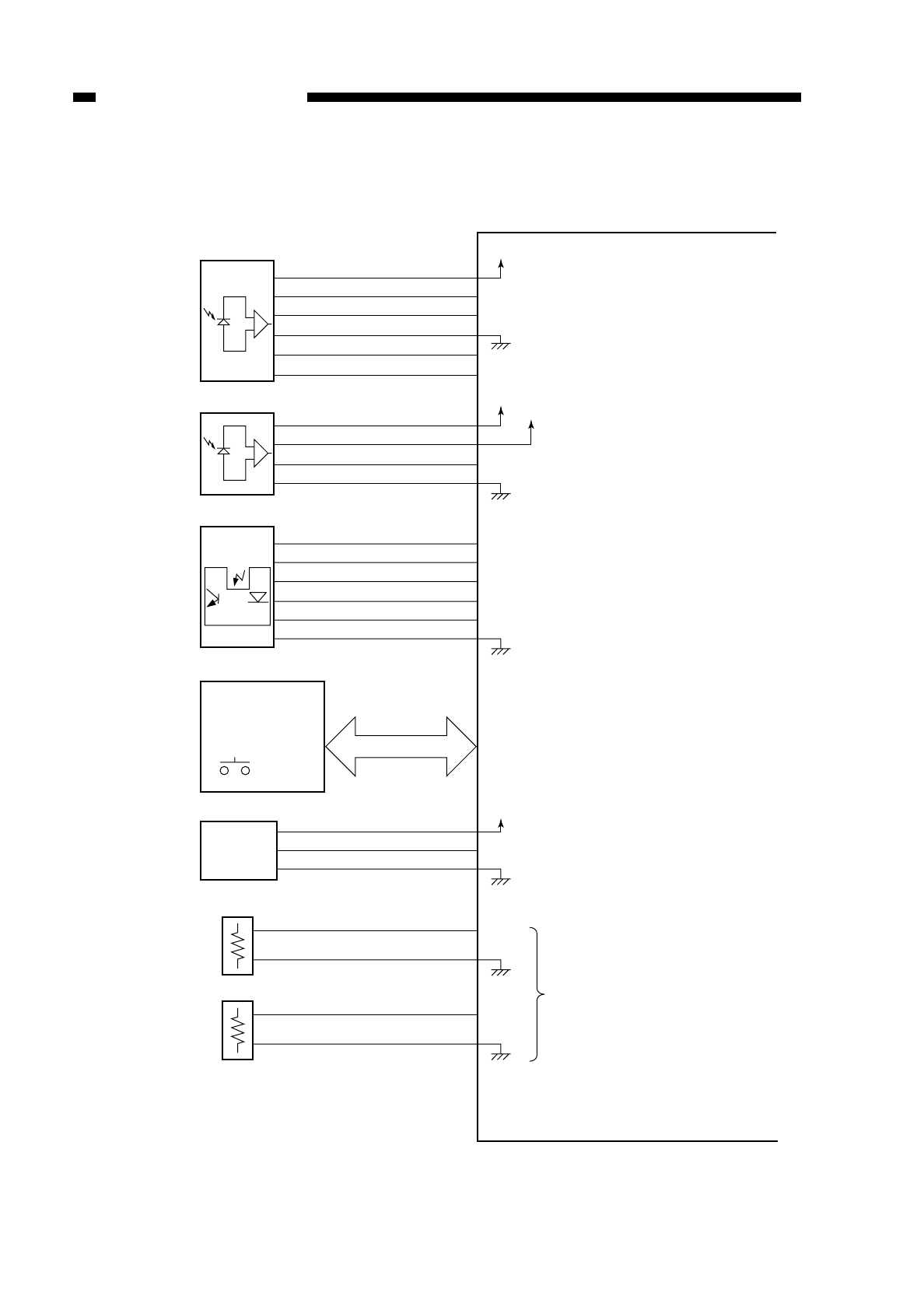
2. Inputs to the DC Controller PCB (2/3)
Figure 2-106
COPYRIGHT
©
1997 CANON INC. CANON NP6218 REV. 0 MAY 1997 PRINTED IN JAPAN (IMPRIME AU JAPON)
CHAPTER 2 BASIC OPERATION
2-6
See p. 6-1.
J651
-6
-5
-4
-3
-2
-1
J314
-7
-8
-9
-10
-11
-12
J313
-4
-5
-6
J304
-3
-4
J304
-1
-2
J309
J310
J801
J802
CS
CSZ_1
CSZ_2
CSZ_3
CSZ_4
Cassette size
sensor
Control panel
Main switch
Multifeeder paper
width detection
Main thermistor
(TH1)
Sub thermistor
(TH2)
See p. 5-8.
J601
-1
-2
-3
-4
J307
-7
-6
-5
-4
J604-2
-1
J356-1
-2
AE sensor
See p. 4-27.
See p. 4-4.
J701
-2
-4
-3
-1
J317
-3
-5
-4
-2
Light adjusting
sensor
AE
AEREF
AEVR1
AEVR2
+24V
+24V +5V
L1D
MFPWD
TH1
TH2
VR1
SW829
DC controller PCB
On the control panel PCB, keys and
LEDs are arranged in a matrix; and
the DC controller turns on the LEDs or
reads key input. The main switch is
part of the control panel. (p. 7-2)
Detects the width of copy paper
loaded in the multifeeder.
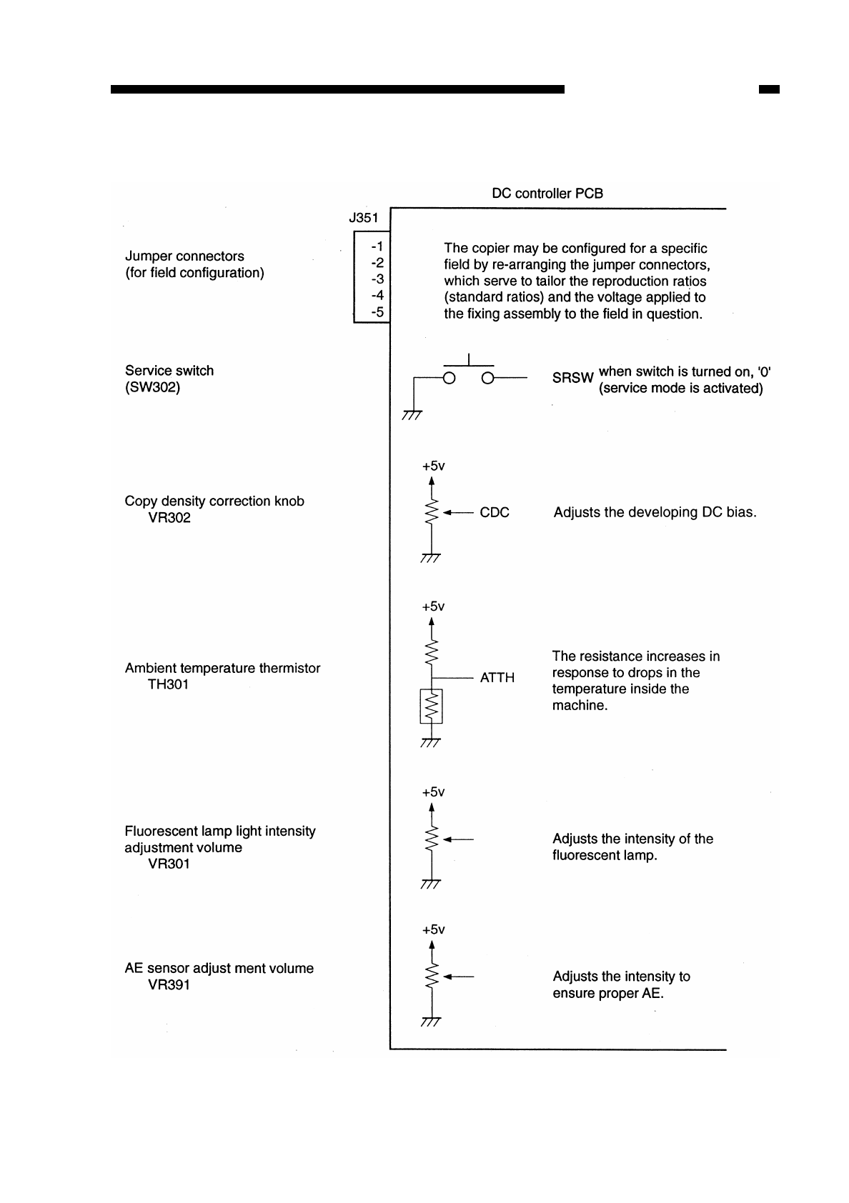
3. Inputs to the DC Controller PCB (3/3)
Figure 2-107
COPYRIGHT
©
1997 CANON INC. CANON NP6218 REV. 0 MAY 1997 PRINTED IN JAPAN (IMPRIME AU JAPON)
CHAPTER 2 BASIC OPERATION
2-7
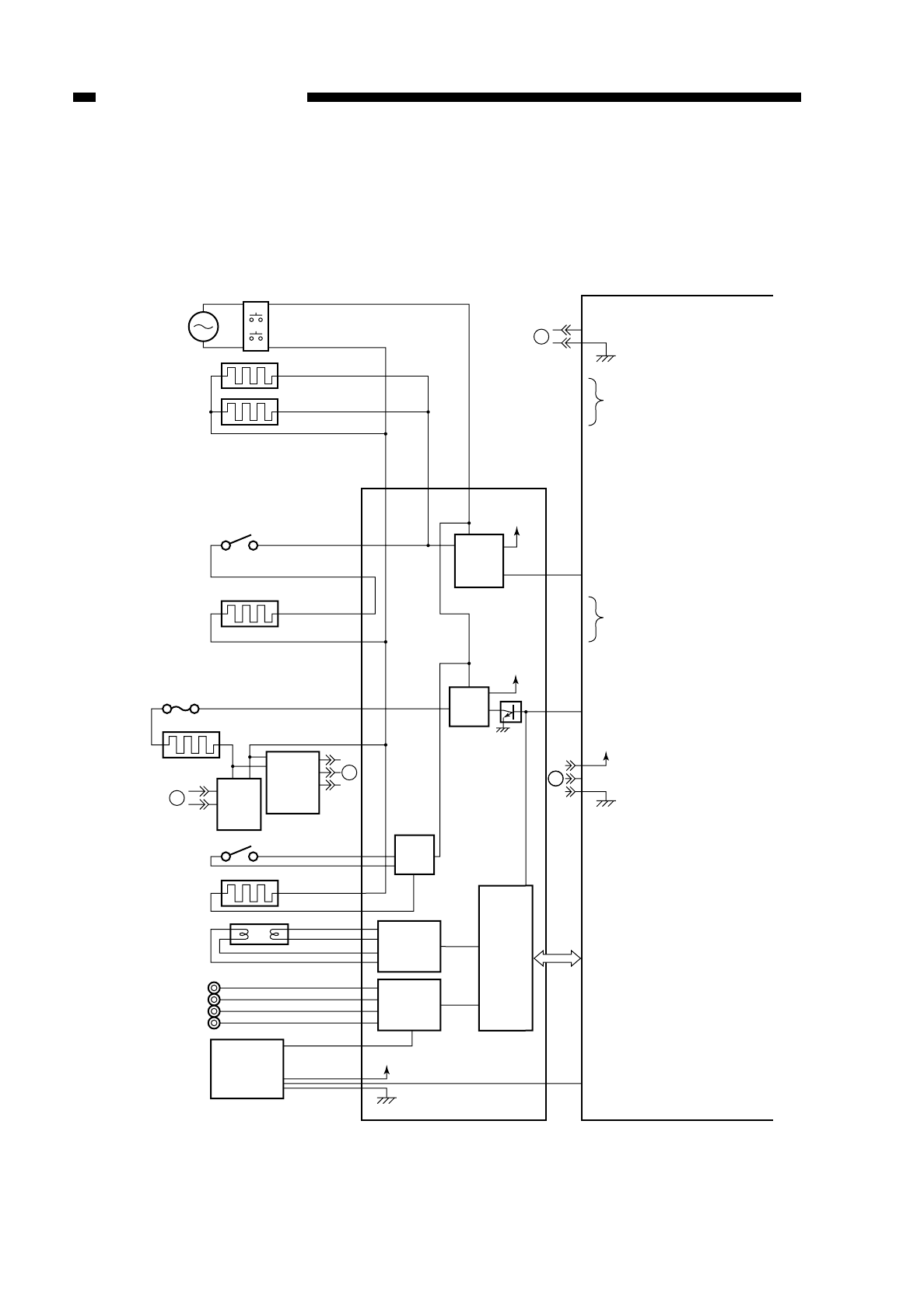
F. Outputs from the DC Controller PCB
1. Outputs from the DC Controller PCB (1/3)
Figure 2-108
COPYRIGHT
©
1997 CANON INC. CANON NP6218 REV. 0 MAY 1997 PRINTED IN JAPAN (IMPRIME AU JAPON)
CHAPTER 2 BASIC OPERATION
2-8
BP102 BP103 BP101
+5V
25V
+5V
+24V
A
BB
A
RL102
RL101
Q512
HTON*
PWSW*
TEP*
HTRD
EHTRL*
Cassette heater (H4)
Cassette heater (H5)
Anti-condensation
switch (SW1)
Lens heater (R1)
Fuse (FU1)
Fixing heater
(H1)
Fluorescent lamp heater
switch (SW2)
Fluorescent lamp heater
(H2)
Fluorescent lamp
(FL1)
Primary charging roller
Developing cylinder
Transfer roller
Static eliminator
Door switch
Fixing
heater
driver
Heater
ON
detection
PCB
Toner level
detection
sensor
Thermal
control
circuit
Scanning
lamp control
circuit
High-voltage
circuit
Composite power
supply PCB
Micro-
processor
DC controller PCB
See p. 6-1.
When '0', RL102 turns on
When '0' RL102 turns on.
When L102 turns on,
SW1 turns on,
and heater (R1) turn on.
When '0', RL101
turns on.
(on when power is turned on)
When heater is on, '0'.
Communication with composite
power supply PCB.
When '0',cartridge
indicator turns on.
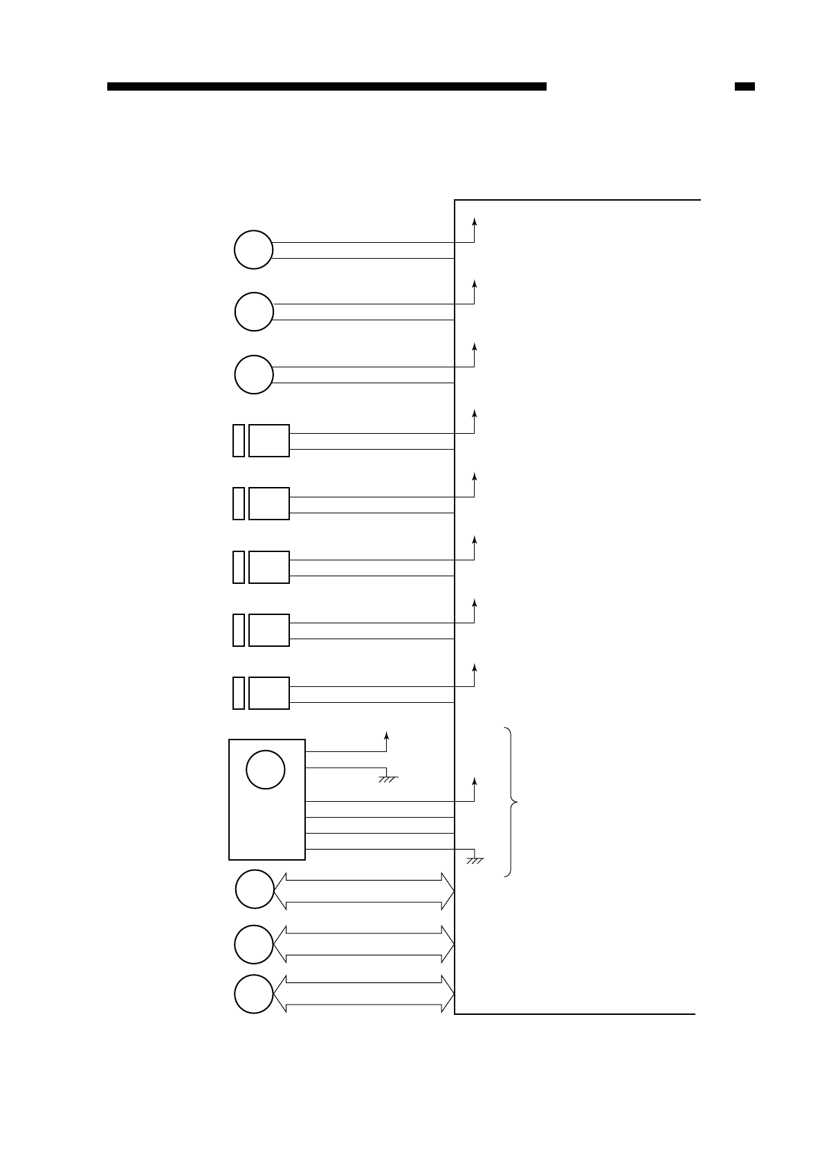
2. Outputs from the DC Controller PCB (2/3)
Figure 2-109
COPYRIGHT
©
1997 CANON INC. CANON NP6218 REV. 0 MAY 1997 PRINTED IN JAPAN (IMPRIME AU JAPON)
CHAPTER 2 BASIC OPERATION
2-9
When '0', registration clutch turns on.
(registration roller rotates)
RGCLD*
DC controller PCB
CL1
+24V
J303
-6
-5
Registration
clutch
When '0', pick-up clutch turns on.
(pick-up roller rotates)
PUCLD1*
CHSLD*
CL2
+24V
J303
-8
-7
Pick-up clutch
When '0', multifeeder pick-up
clutch turns on.
(multifeeder pick-up roller rotates)
MFPUCLD*
CL3
+24V
J306
-9
-10
Multifeeder
pick-up clutch
When '1', solenoid turns off.
(blank width control)
When '0', solenoid turns on.
(lens mount moves)
SL1
+24V
Change
solenoid
When '0', solenoid turns on.
(holding plate released)
When '0', solenoid turns on.
(blank shutter opens)
When '0', solenoid turns on.
(cleaning pad butted)
When '0', solenoid turns on.
(causing transfer roller
to move down)
See p. 5-1.
See p. 3-7.
See p. 3-3.
See p. 6-10.
MLOCK*
MMD
+5V
+34V
M1
M2
J206
-1
-2
J501
-1
-2
J502
-4
-1
-2
-3
J03
-1
-4
-3
-2
J305
Main motor
Scanner motor
Lens motor M3
J306
Main motor
drive PCB
MFSLD*
SL2
+24V
Multifeeder
holding plate
solenoid
BSSLD*
SL3
+24V
Blank shutter
solenoid
PCLSLD*
SL4
+24V
Primary charging
roller cleaning
solenoid
TRSLD*
SL5
+24V
J313
-10
-11
J308
-9
-10
J315
-4
-5
J306
-11
-12
J306
-7
-8
Transfer charging
roller releasing
solenoid
Fixing film motor M4
J304

3. Outputs from the DC Controller PCB (3/3)
Figure 2-110
COPYRIGHT
©
1997 CANON INC. CANON NP6218 REV. 0 MAY 1997 PRINTED IN JAPAN (IMPRIME AU JAPON)
CHAPTER 2 BASIC OPERATION
2-10
+24V
J316
-1
-2
J315
-7
-6
J320
-1
J310
-4
-1
-2
-3
J802
-13
-16
-15
-14
J803
-2
-4
-3
-1
-2
J401
-1
-2
HEFD*
+24V
PEXP*
+24V
TCNTD*
+5V
CCD*
CCDT*
Heat exhaust fan
(FM1)
Pre-exposure
lamp
Total copy count
Control
card
IV N
Control
panel
DC controller PCB
When '0', heat exhaust fan on.
(heat exhaust fan rotates)
When '0', the pre-exposure lamp
turns on.
When changes from '0' to '1',
count is incremented.
When '0', count is incremented.
When '0', control card is present.
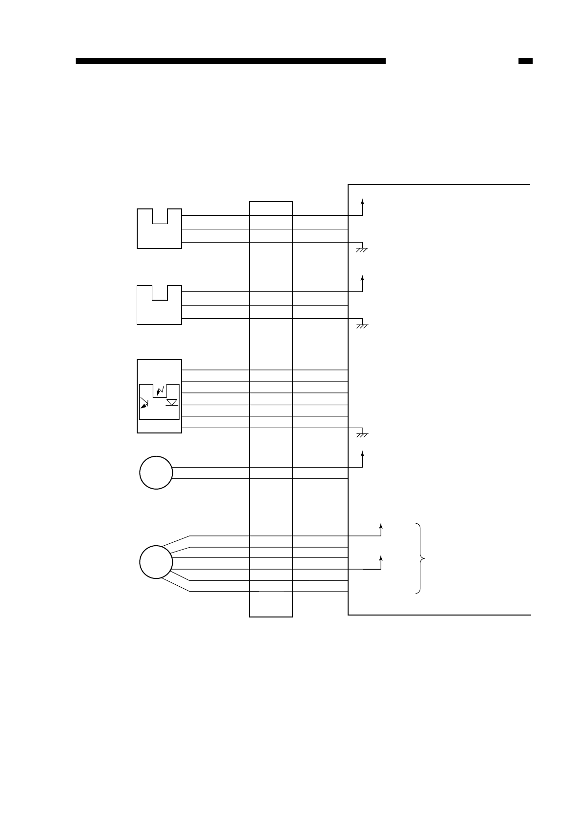
G. Inputs to and Outputs from the 1-Cassette Unit Driver PCB
1. Inputs to and Outputs from the 1-Cassette Unit Driver PCB (1/1)
Figure 2-111
COPYRIGHT
©
1997 CANON INC. CANON NP6218 REV. 0 MAY 1997 PRINTED IN JAPAN (IMPRIME AU JAPON)
CHAPTER 2 BASIC OPERATION
2-11
5V
J110
-1
-3
-2
J110
-4
-6
-5
PS1cu C2VPD
Cassette 2
vertical path
sensor
5V
PS2cu C2PD
Cassette 2
paper sensor
When PS1 detects paper, '1'.
(when the light-blocking plate
is at PS1cu, '1')
When paper is present in
cassette, '0'.
(when light-blocking plate
is not at PS2cu, '0')
Cassette driver PCB
DC controller PCB
J651
-6
-5
-4
-3
-2
-1
J110
-7
-8
-9
-10
-11
-12
CS2
C2SZ_1
C2SZ_2
C2SZ_3
C2SZ_4
Cassette 2
size detection See p. 5-8.
CMA
CMA*
CMB
CMB*
J114
-1
-2
-3
-4
-5
-6
Cassette
unit motor
While M1cu is rotating,
alternates between '1' and
'0'. (pulse signal)
When '0', pick-up clutch turns on.
(pick-up roller rotates)
C2PUCLD*
CL1cu
M1cu
+24V
+24V
+24V
J115
-1
-2
Cassette 2
pick-up clutch
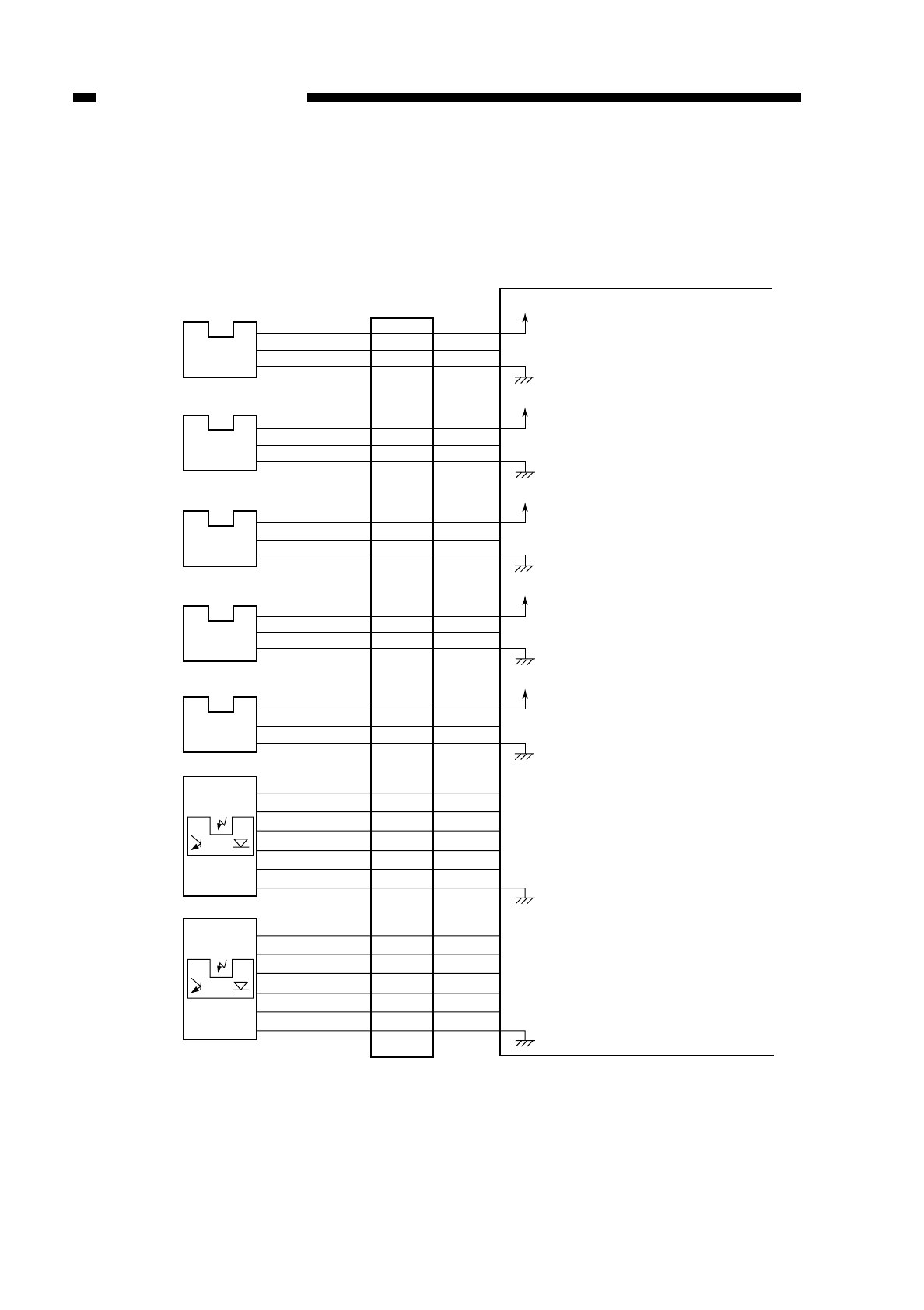
H. Inputs to and Outputs from the 2-Cassette Unit Driver PCB
1. Inputs to and Outputs from the 2-Cassette Unit Driver PCB (1/2)
Figure 2-112
COPYRIGHT
©
1997 CANON INC. CANON NP6218 REV. 0 MAY 1997 PRINTED IN JAPAN (IMPRIME AU JAPON)
CHAPTER 2 BASIC OPERATION
2-12
5V
J110
-1
-3
-2
J110
-4
-6
-5
PS1cu C2UPD
Cassette 2
vertical path
sensor
5V
PS2cu CS2PD*
Cassette 2
sensor
When PS1cu detects paper, '1'.
(when light-blocking plate is at
PS1cu, '1')
When paper is present in cassette, '0'.
(when light-blocking plate is not at
PS2cu, '0')
5V
J120
-13
-15
-14
J120
-10
-12
-11
PS3cu C3VPD
Cassette 3
vertical path
sensor
5V
PS4cu CS3PD*
Cassette 3
paper sensor
When PS3cu detects paper, '1'.
(when light-blocking plate is at PS3cu, '1')
When paper is present in cassette, '0'.
(when light-blocking pale
is not at PS4cu, '0')
5V
J120
-1
-3
-2
PS5cu CRDOP*
Cassette right
door
open/closed
sensor
When right door is opens, '0'.
(when light-blocking plate
is not at PScu, '0')
Cassette driver PCB
DC controller PCB
J651
-6
-5
-4
-3
-2
-1
J110
-7
-8
-9
-10
-11
-12
CS2
C2SZ_1
C2SZ_2
C2SZ_3
C2SZ_4
Cassette 2 size
detection See p. 5-8.
J651
-6
-5
-4
-3
-2
-1
J120
-4
-5
-6
-7
-8
-9
CS3
C3SZ_1
C3SZ_2
C3SZ_3
C3SZ_4
Cassette 3 size
detection See p. 5-8.
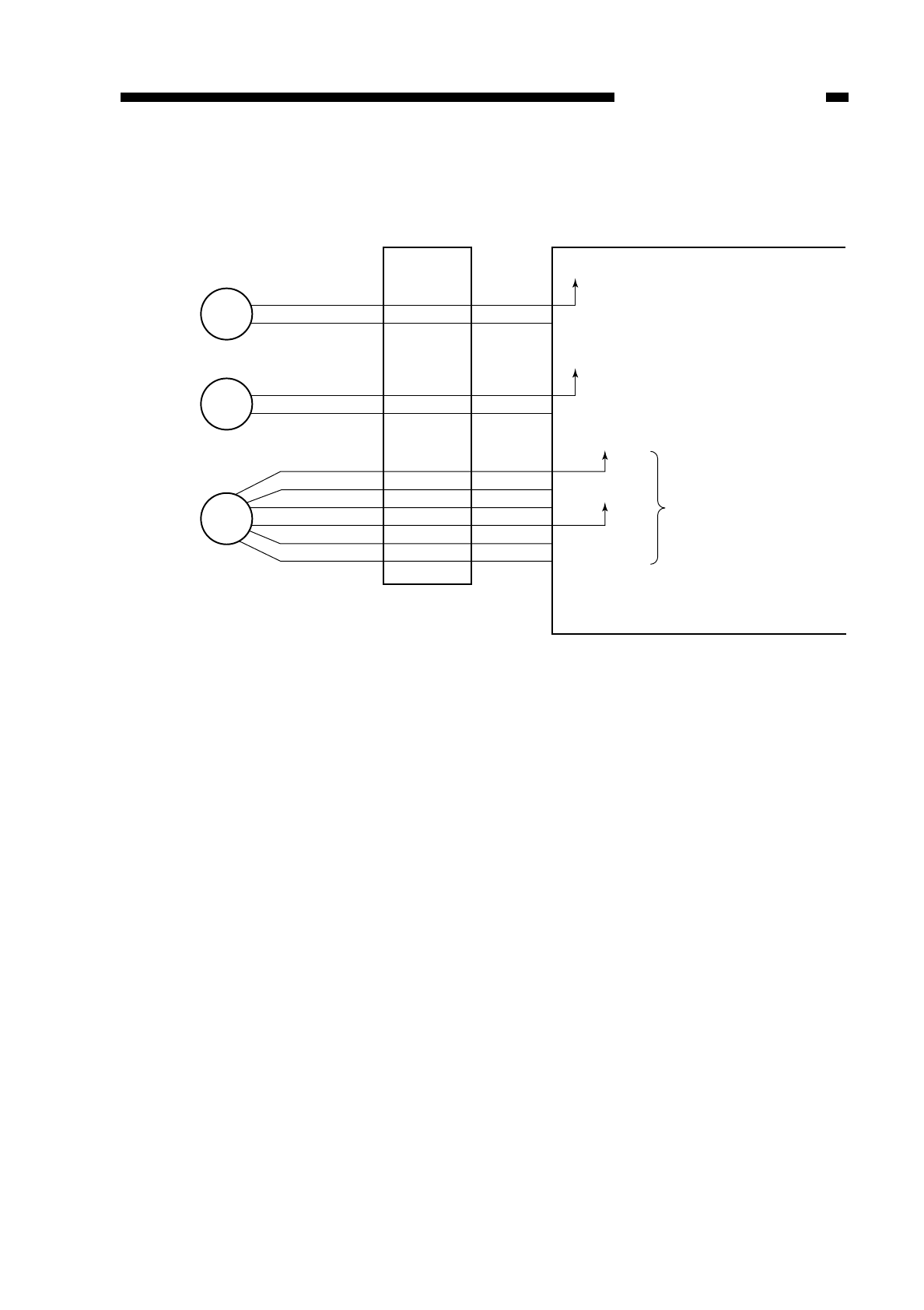
2. Inputs to and Outputs from the 2-Cassette Unit Driver PCB (2/2)
Figure 2-113
COPYRIGHT
©
1997 CANON INC. CANON NP6218 REV. 0 MAY 1997 PRINTED IN JAPAN (IMPRIME AU JAPON)
CHAPTER 2 BASIC OPERATION
2-13
Cassette driver PCB DC controller PCB
CMA
CMA*
CMB
CMB*
J114
-1
-2
-3
-4
-5
-6
Cassette
unit motor
While M1cu is rotating,
alternates between '1' and '0'.
(pulse signal)
M1cu
When '0', pick-up clutch turns on.
(pick-up roller rotates)
C2PUCLD*
CL1cu
+24V
+24V
+24V
J125
-1
-2
Cassette 2
pick-up clutch
When '0', the pick-up clutch turns on.
(pick-up roller rotates)
C4PUCLD*
CL2cu
+24V
J125
-3
-4
Cassette 3
pick-up clutch

COPYRIGHT
©
1997 CANON INC. CANON NP6218 REV. 0 MAR. 1997 PRINTED IN JAPAN (IMPRIME AU JAPON)
CHAPTER 2 BASIC OPERATION
2-14

COPYRIGHT
©
1997 CANON INC. CANON NP6218 REV. 0 MAY 1997 PRINTED IN JAPAN (IMPRIME AU JAPON)
CHAPTER 3
EXPOSURE SYSTEM
I. BASIC OPERATION ...........................3-1
A. Varying the Reproduction Ratio ....3-1
II. LENS DRIVE SYSTEM ......................3-1
A. Outline ...........................................3-1
B. Lens Motor Drive Circuit................3-3
C. Basic Sequence of Operations
(lens drive system; non-Direct)......3-4
III. SCANNING DRIVE SYSTEM.............3-5
A. Driving the Scanner.......................3-5
IV. DISASSEMBLY AND ASSEMBLY ......3-9
A. Scanner Drive Assembly ...............3-9
B. Lens Drive Assembly.....................3-18
This chapter discusses the principles of operation used for the copier’s lens drive unit and scanner
drive unit. It also explains the timing at which these drive units are operated, and shows how they may
be disassembled/assembled and adjusted.
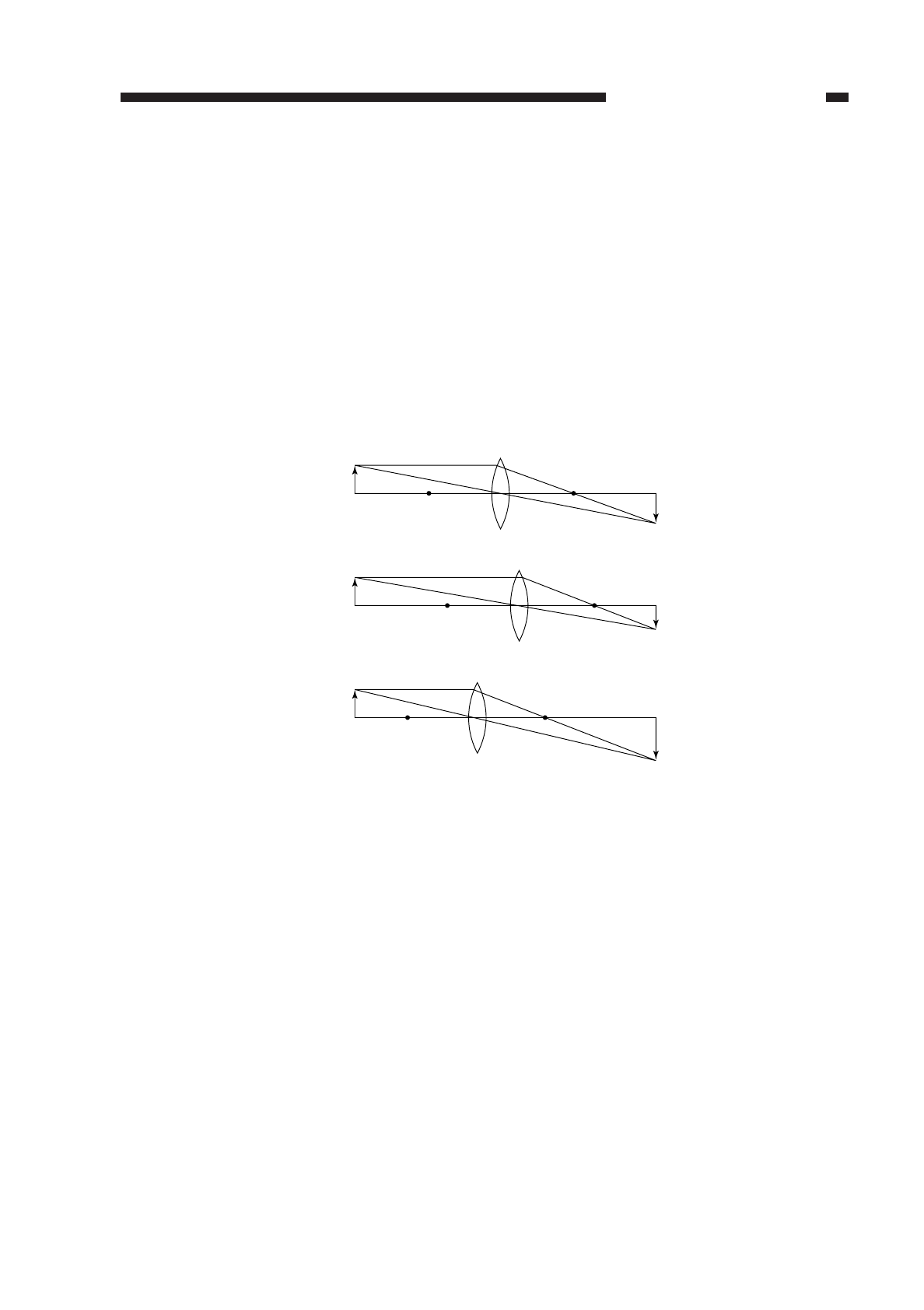
I. BASIC OPERATION
A. Varying the Reproduction Ratio
The reproduction ratio across the photosensitive drum is varied by the lens drive
system; on the other hand, the ratio around the drum is varied by the scanner drive
system.
The lens drive system uses a zoom lens; as shown in Figure 3-101, the position and
focal distance of the lens are changed to vary the reproduction ratio across the
photosensitive drum.
The scanner drive system varies the reproduction ratio around the photosensitive
drum by moving the No. 1 mirror relatively faster (reduction) or slower (enlargement) than
the peripheral speed of the photosensitive drum.
Figure 3-101
II. LENS DRIVE SYSTEM
A. Outline
The lens drive system is driven by the lens motor (M3). The drive of the lens motor
is transmitted to the blank exposure unit through a relay gear. (See p. 4-18.)
When the lens is moved, the solenoid (SL1) is turned on to engage the relay gear
with the lens gear; when the lens motor rotates in the direction of the arrow in this
condition, the lens is moved in the direction of enlargement (
←) by the work of the relay
lens gear and lens cable.
The blank exposure shutter, on the other hand, moves according to the distance
traveled by the lens for reduction, thereby blanking (whiting) out the areas on both ends
of the copy.
The copier’s scanner lens home position sensor (PS2) is located at the center of the
scanner lens drive rail so that the scanner lens home position may be detected early
upon power-on, thereby speeding up the generation of the first copy. In addition, the
scanning lens moves to the appropriate position in response to a press on each ratio
button, thereby shortening the time it takes to generate the first copy.
COPYRIGHT
©
1997 CANON INC. CANON NP6218 REV. 0 MAY 1997 PRINTED IN JAPAN (IMPRIME AU JAPON)
CHAPTER 3 EXPOSURE SYSTEM
3-1
F
F'
F1
F2
F2'
F1'
Direct
Reduce
Enlarge
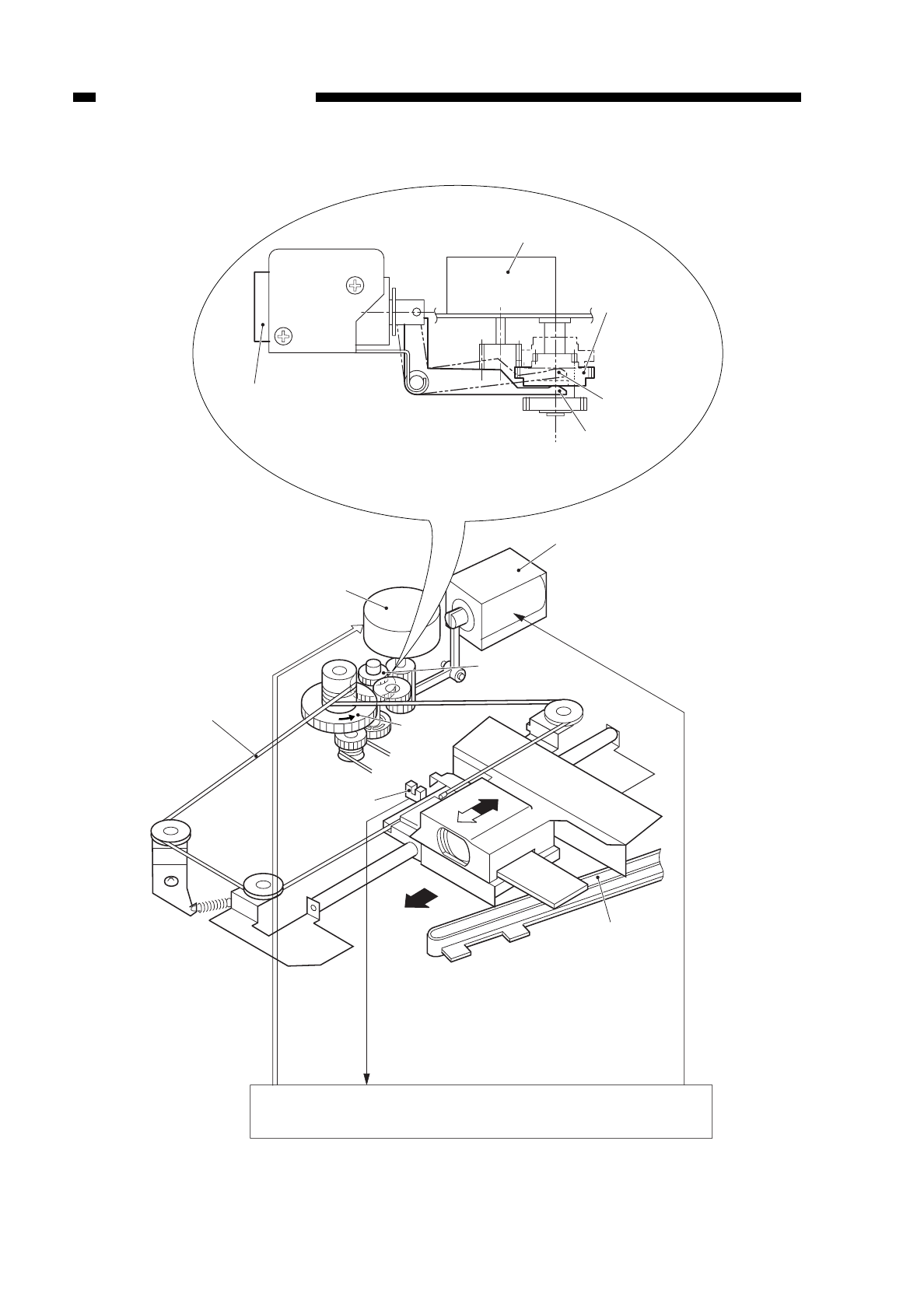
Figure 3-201
COPYRIGHT
©
1997 CANON INC. CANON NP6218 REV. 0 MAY 1997 PRINTED IN JAPAN (IMPRIME AU JAPON)
CHAPTER 3 EXPOSURE SYSTEM
3-2
Change solenoid (SL1)
Lens motor (M3)
Lens cable
Lens motor (M3)
Change solenoid (SL1)
Relay gear
SL1 'ON'
(lens drive)
SL1 'OFF'
(blank exposure
unit drive)
Lens home
position sensor
(PS2)
Lens gear
Relay gear
Lens
Cam groove
Enlargement
Lens motor drive signal
Change solenoid drive signal (CHSLD*)
Lens home position
detection signal (LHP)
DC controller
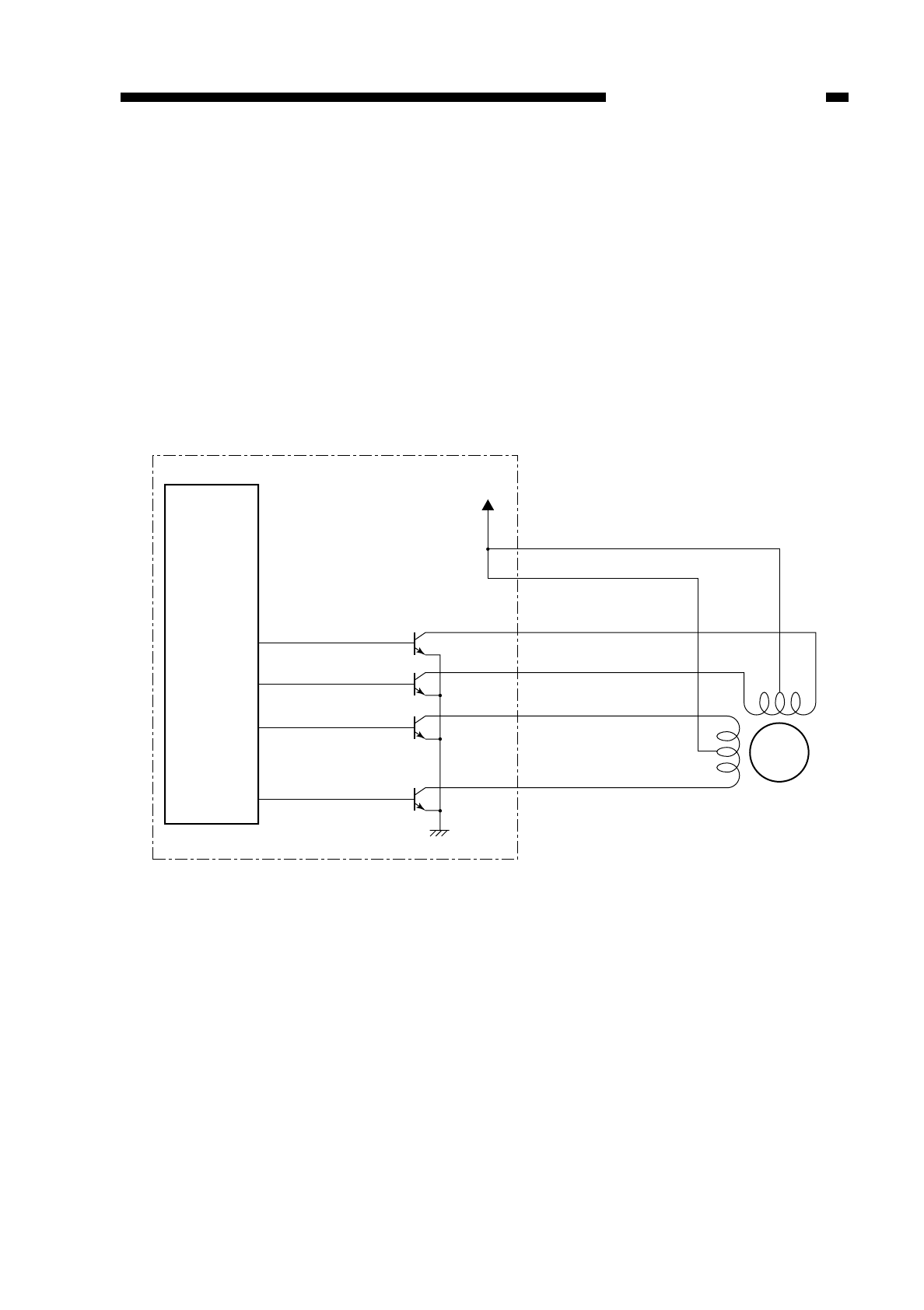
B. Lens Motor Drive Circuit
The lens motor (M3) is a stepping motor and rotates in response to drive power
LNSC-A and LNSC-B and pulse signals LNSA, LNSA*, LNSB, and LNSB*.
1. Keeping the Lens Motor Stationary
All LNSA, LNSA*, LNSB, and LNSB* are caused to go OFF, thereby stopping and
retaining the motor stationary.
2. Driving the Lens Motor
Pulses are applied to each phase in sequence to rotate the motor.
Figure 3-202
COPYRIGHT
©
1997 CANON INC. CANON NP6218 REV. 0 MAY 1997 PRINTED IN JAPAN (IMPRIME AU JAPON)
CHAPTER 3 EXPOSURE SYSTEM
3-3
LNSC-B
LNSC-A
LNSA
LNSA*
LNSB
LNSB*
J306
- 1
34V
- 4
- 5
- 6
- 2
- 3
M3
DC controller PCB
Microprocessor
(Q301)
Lens motor
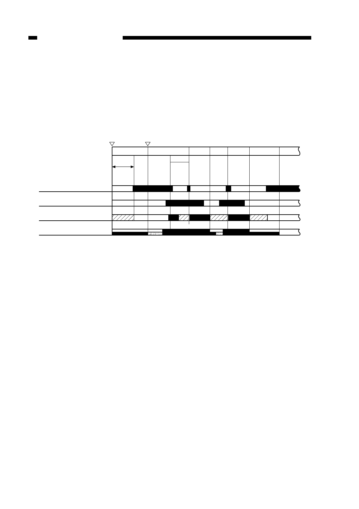
C. Basic Sequence of Operations (lens drive system; non-Direct)
When a specific reproduction ratio is selected, the lens always returns to the home
position before moving to the position appropriate to the selected ratio. This also holds
true when the reproduction ratio is reset to Direct.
Figure 3-203
COPYRIGHT
©
1997 CANON INC. CANON NP6218 REV. 0 MAY 1997 PRINTED IN JAPAN (IMPRIME AU JAPON)
CHAPTER 3 EXPOSURE SYSTEM
3-4
INTR
Power switch
ON Copy Start key
ON
STBY SCFW SCRV SCFW SCRV LSTR
AER
∗
Scanner home position sensor
(PS1)
Registration sensor (PS6)
Scanner
Scanning lamp
Forward
Reverse
Half pre-heating Full pre-
heating Half pre-
heating
*Unless it is at the home position already, the scanner returns to the home position at power-on.
ON Pre-heating
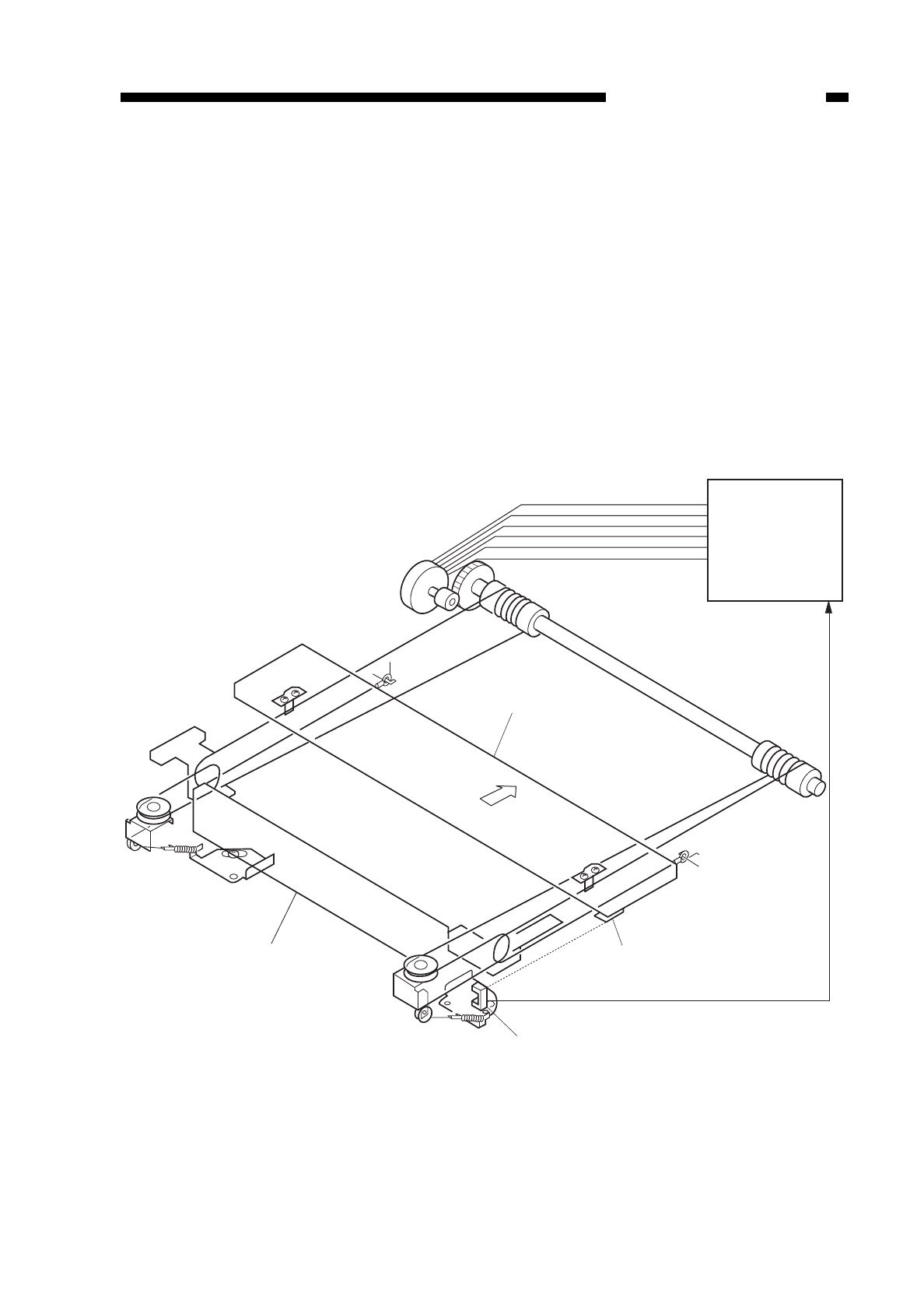
III. SCANNING DRIVE SYSTEM
A. Driving the Scanner
1. Outline
The scanner drive system is driven by the scanner motor (M2). The scanner motor
changes the direction of its rotation between when the scanner moves forward and when
it moves in reverse; the speed of its rotation varies according to the selected
reproduction ratio. However, the speed of its rotation remains constant regardless of the
reproduction ratio when the scanner is moving in reverse; 2. 5 times as fast as when the
scanner is moving forward.
The distance traveled by the scanner varies according to the length of copy paper
and the selected reproduction ratio.
Figure 3-301
COPYRIGHT
©
1997 CANON INC. CANON NP6218 REV. 0 MAY 1997 PRINTED IN JAPAN (IMPRIME AU JAPON)
CHAPTER 3 EXPOSURE SYSTEM
3-5
SC-COM A
SC-COM B
SC-A
SC-A*
SC-B
SC-B*
DC controller
PCB
No. 2 mirror mount
No. 1 mirror mount
Forward
PS1 light-blocking plate
Scanner home position detection signal (SCHP)
Scanner home position sensor (PS1)
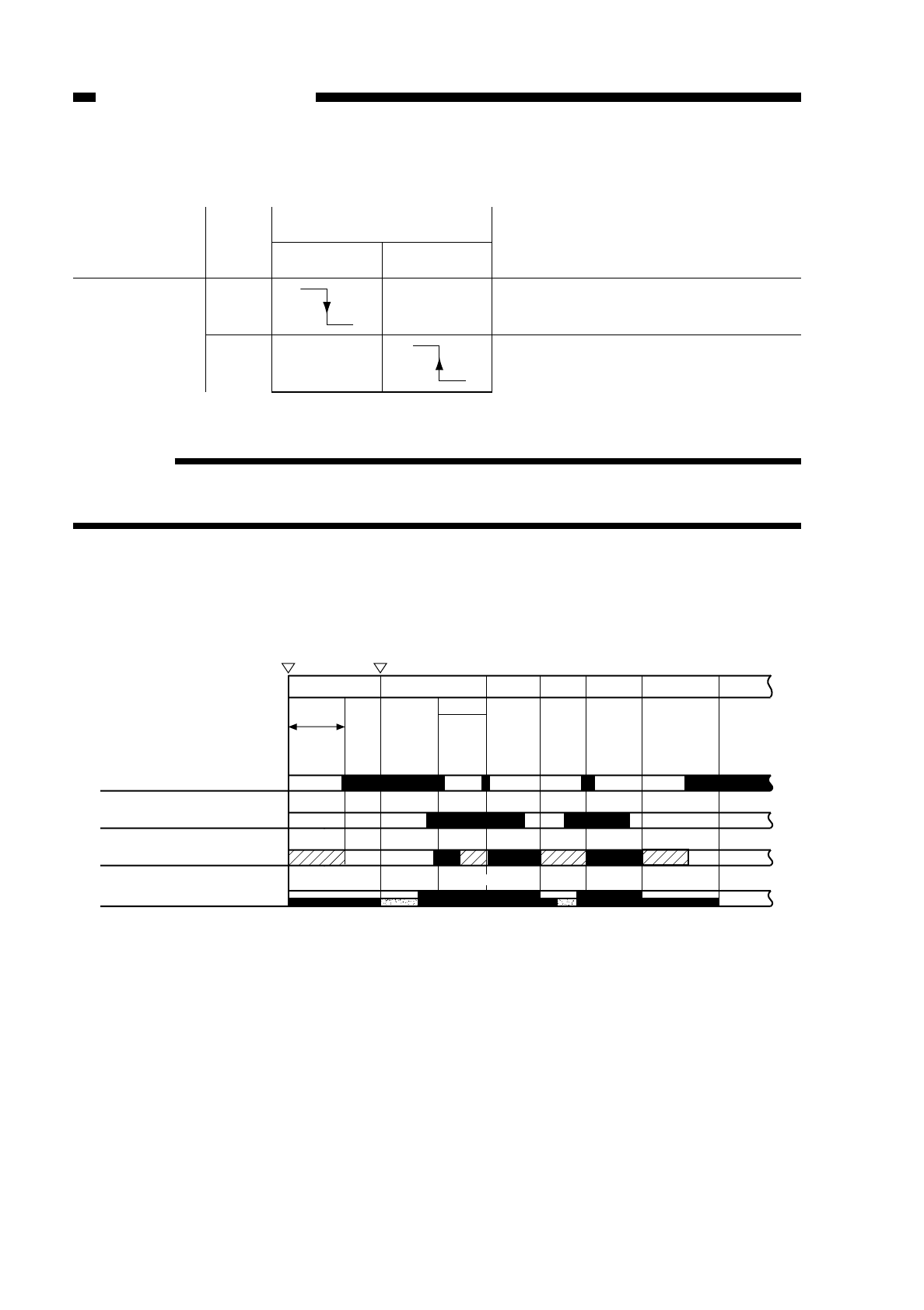
2. Relationship between the Scanner Sensor and Signals
Table 3-301
Reference:
The registration clutch is turned on in response to a press on the Copy Start key or
when the scanner starts to move forward.
3. Basic Sequence of Operations (scanner)
Figure 3-302
COPYRIGHT
©
1997 CANON INC. CANON NP6218 REV. 0 MAY 1997 PRINTED IN JAPAN (IMPRIME AU JAPON)
CHAPTER 3 EXPOSURE SYSTEM
3-6
Scanner sensor
PS1 (scanner
home position
sensor)
SCHP
Signal Scanner
Forward Reverse
Registration clutch turns on.
After 0.1 sec, the scanner stops moving
in reverse.
Description
LSTR
INTR
Power switch
ON Copy Start key
ON
STBY SCFW SCRV SCFW SCRV
AER
Scanner home position sensor
(PS1)
Registration sensor (PS6)
Scanner
Scanning lamp
Forward
Reverse
Half pre-heating Full pre-
heating Half pre-
heating
∗Unless it is at the home position already, the scanner returns to the home position at power-on.
ON Prehe-ating
∗
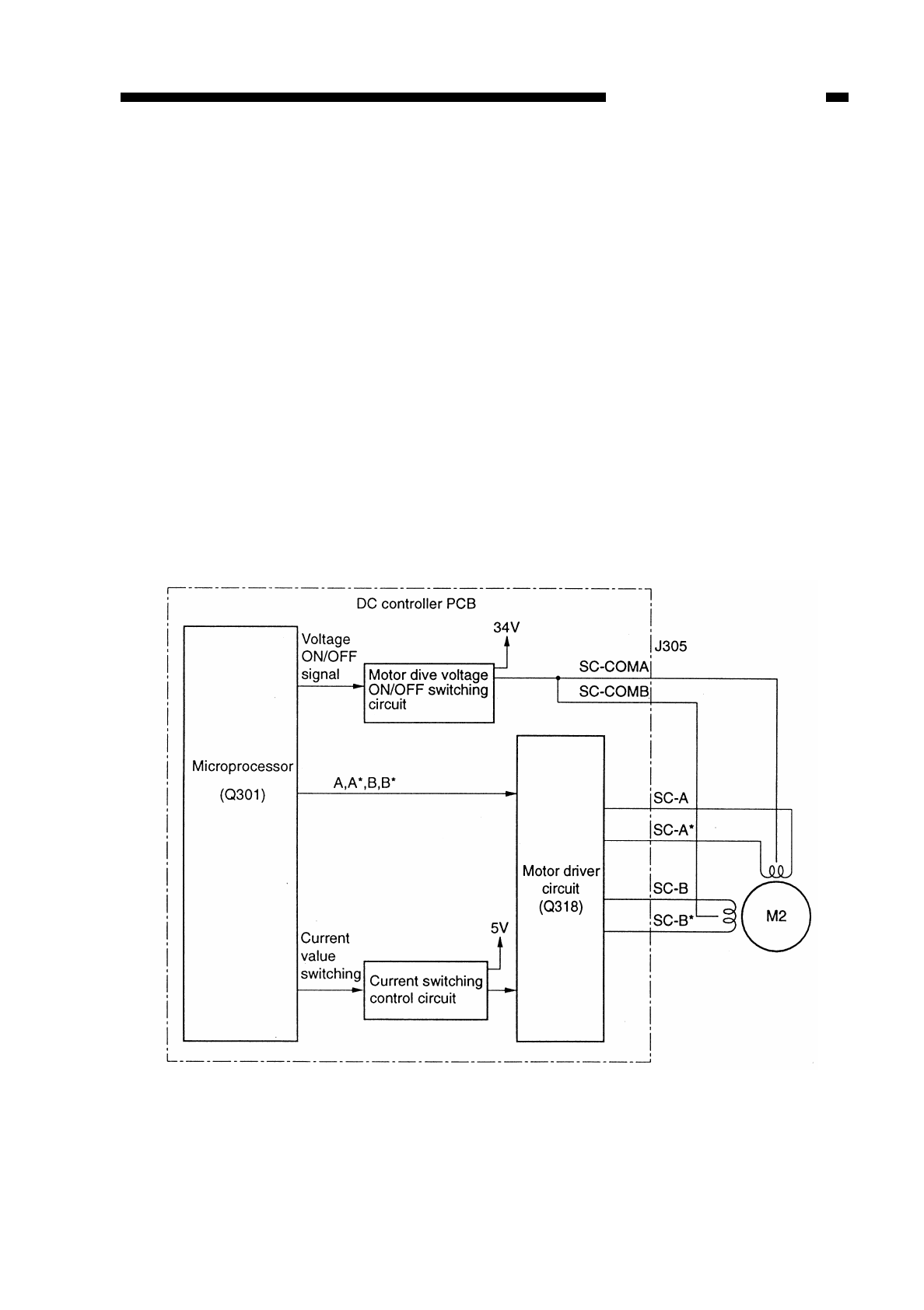
4. Driving the Scanner Motor
a. Outline
The scanner motor (M2) is a 4-phase control stepping motor. The direction and the
speed of the scanner motor (M2) are switched by controlling the output timing of drive
power SC-COMA and SC-COMB and pulse signals A, A*, B, and B*.
b. Mechanism
The microprocessor (Q301) on the DC controller PCB receives such instructions as
on copy mode and reproduction ratio from the control panel circuit; in response, it sends
drive pulses to the scanning motor (M2) through the motor drive circuit.
The scanner motor is a 4-phase control stepping motor, and is used to control the
sequence of drive pulses (SC-A through SC-B*) and frequency, thereby controlling the
direction of scans and speed.
The motor drive voltage ON/OFF switching circuit supplies or deprives the motor with
or of power, thereby controlling the motor drive.
The current switching control circuit sets the current that flows through the motor
according to the revolution, and the motor driver circuit controls the constant current
according to the value that has been set.
Figure 3-303
COPYRIGHT
©
1997 CANON INC. CANON NP6218 REV. 0 MAY 1997 PRINTED IN JAPAN (IMPRIME AU JAPON)
CHAPTER 3 EXPOSURE SYSTEM
3-7
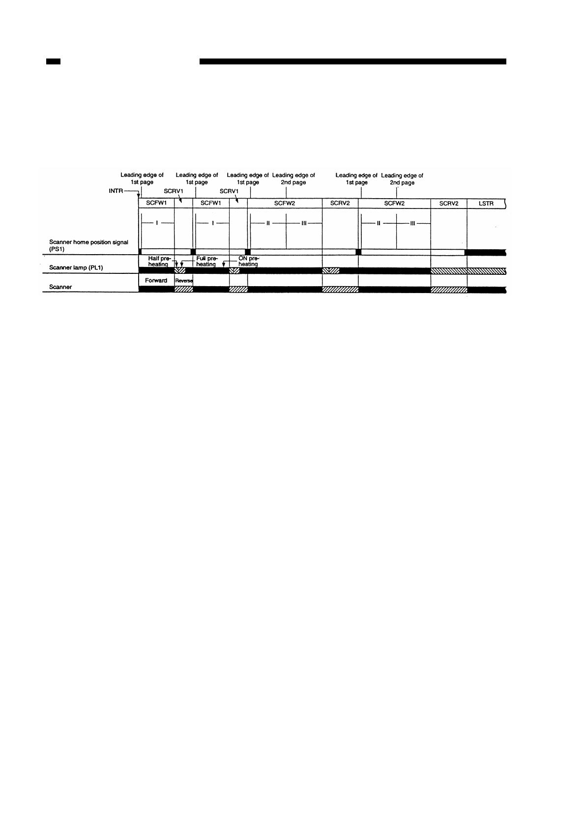
5. Scanner Operations in Page Separation Mode (non-AE, page separation, A4, 2
copies)
Figure 3-304
I, II, and III shown in Figure 3-108 are controlled by the microprocessor on the DC
controller PCB with reference to the scanner home position signal (falling edge of SCHP)
of the first original.
The microprocessor determines the distance to be traveled by the scanner according
to the size of the selected cassette.
I, II: The distance traveled by the scanner is determined by the reproduction ratio and
cassette size.
III: The copier does not have a mechanism that detects the size of originals; for this
reason, control for page separation is exerted with reference to the size of the
cassette.
If the distance traveled by the scanner forward (II in Figure 3-304) exceeds 216 mm
(approx.), the copier assumes a point corresponding to 216 mm to be the leading
edge of the second page.
The size of originals is checked only if an ADF (accessory) is installed.
The microprocessor identifies the result of dividing the identified size by 2 as the
center of the original and operates the scanner assuming that the center represents
the leading edge of the second original.
COPYRIGHT
©
1997 CANON INC. CANON NP6218 REV. 0 MAY 1997 PRINTED IN JAPAN (IMPRIME AU JAPON)
CHAPTER 3 EXPOSURE SYSTEM
3-8
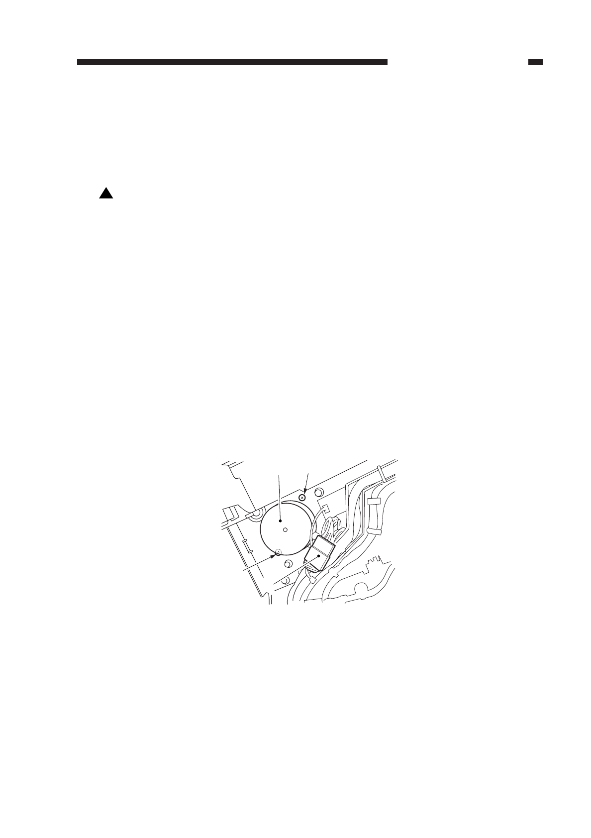
IV. DISASSEMBLY AND ASSEMBLY
This section explains mechanical characteristics and describes how to
disassemble/assemble the machine.
Be sure to observe the following whenever disassembling/assembling the machine:
1. Disconnect the power plug before starting the work.
2. Unless otherwise shown, assemble the parts by reversing the steps given to
disassemble them.
3. Identify each screw by type (length, diameter) and location.
4. A washer is used for one of the mounting screws on the rear cover to protect against
static electricity; be sure to use the washer when assembling the part.
5. A washer is used for some mounting screws (for grounding wire, varistor) to ensure
correct electrical continuity; be sure to use the washer when assembling the part.
6. As a rule, do not operate the machine while any of its parts are removed.
7. When sliding out the duplexing unit or the fixing assembly, be sure to turn off the front
door switch or the power switch.
A. Scanner Drive Assembly
1. Detaching the Scanner Drive Motor
1) Remove the upper rear cover.
2) Disconnect the connector
qof the motor, and remove the two screws w; then,
detach the scanner drive motor e.
Figure 3-401
!
COPYRIGHT
©
1997 CANON INC. CANON NP6218 REV. 0 MAY 1997 PRINTED IN JAPAN (IMPRIME AU JAPON)
CHAPTER 3 EXPOSURE SYSTEM
3-9
e
w
q
w
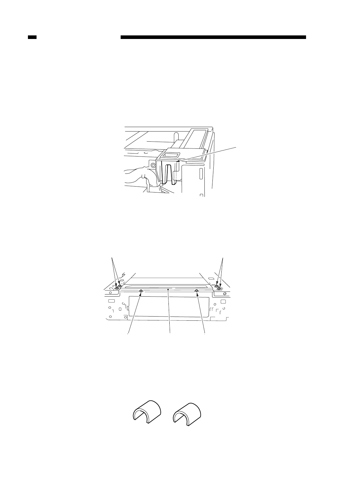
2. Detaching the Scanner Cable
1) Detach the copyboard cover, right cover, left cover, upper rear cover, and lower rear
cover.
2) Detach the copyboard glass.
3) Detach the control panel.
4) Detach the copyboard cover support q.
Figure 3-402
5) Remove the six screws w, and detach the upper left stay e.
Figure 3-403
6) Fix the cable in place using a pully clip (FY9-3010)
Figure 3-404
COPYRIGHT
©
1997 CANON INC. CANON NP6218 REV. 0 MAY 1997 PRINTED IN JAPAN (IMPRIME AU JAPON)
CHAPTER 3 EXPOSURE SYSTEM
3-10
q
w
w
ew
w
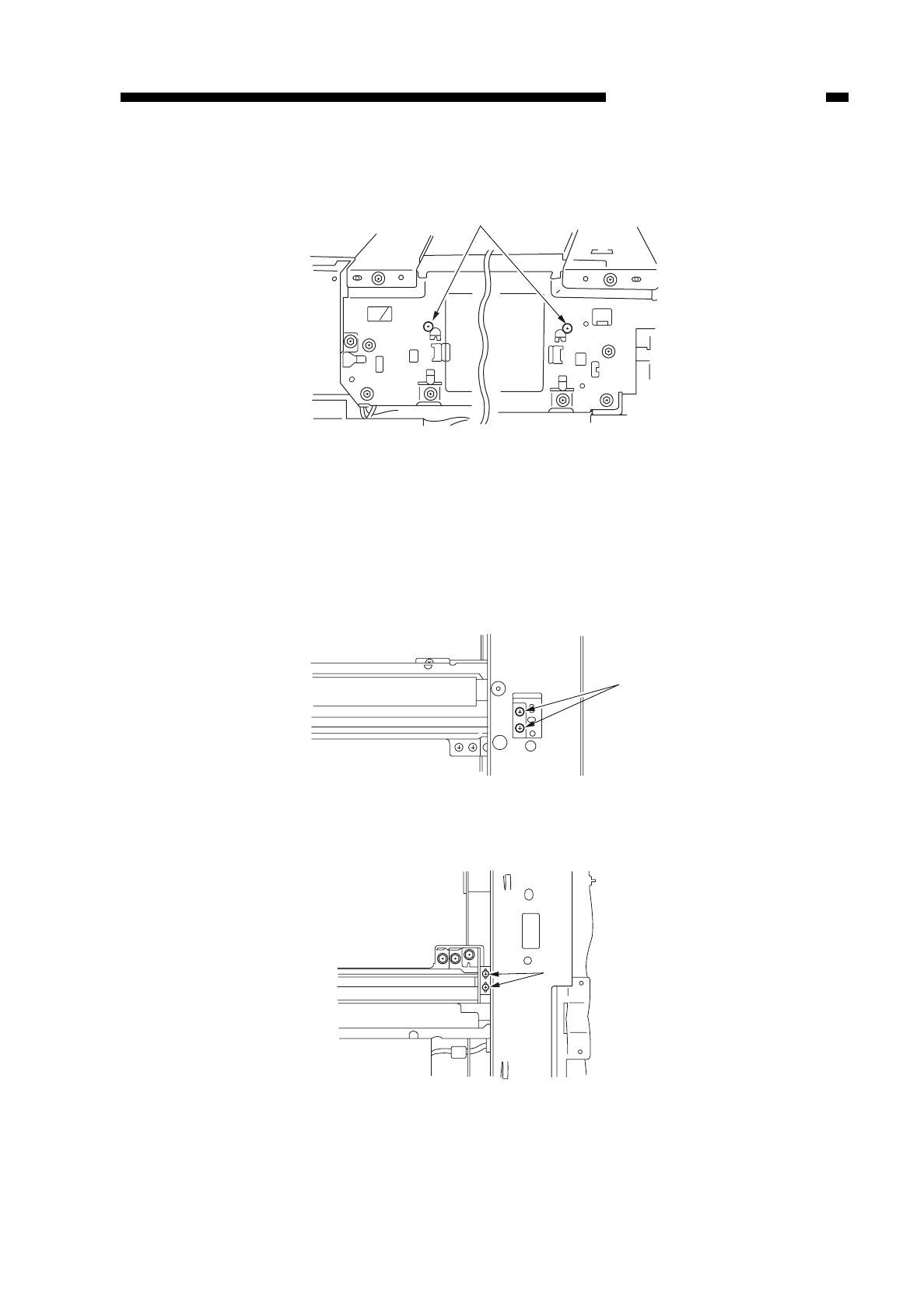
7) Loosen the two screws rto loosen the cable tension (both front and right).
Figure 3-405
8) Move the No. 1 mirror mount to the front to align the long hole in the front side plate
and the cable fixing screw t.
Then, detach the cable fixing screw tto separate the No. 1 mirror mount and the
scanner cable (both front and rear).
Figure 3-406
COPYRIGHT
©
1997 CANON INC. CANON NP6218 REV. 0 MAY 1997 PRINTED IN JAPAN (IMPRIME AU JAPON)
CHAPTER 3 EXPOSURE SYSTEM
3-11
r
t
t
(front)
(rear)
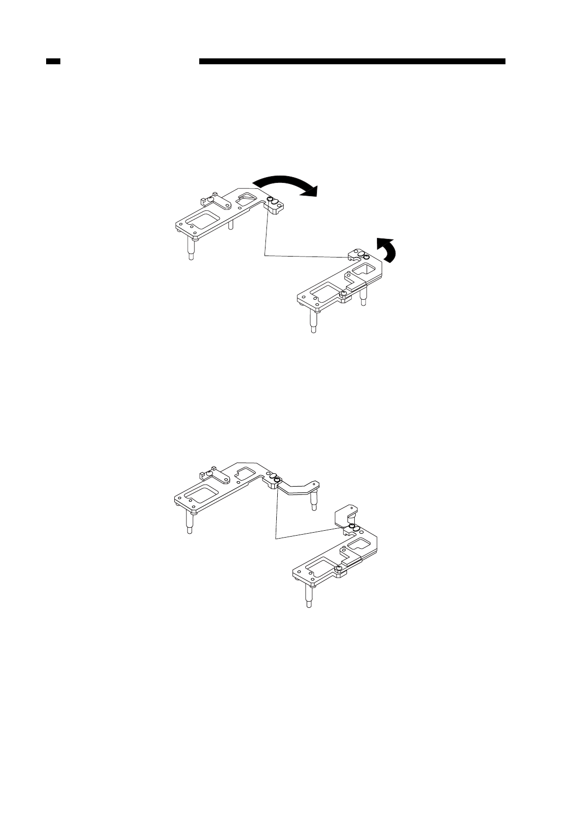
9) Remove the pully clip, and detach the scanner cable (both front and rear).
3. Assembling the Mirror Position Tool
1) Remove the screw found in position B.
Figure 3-407
2) Fit the screw removed in step 1) in position A, and tighten it slightly.
3) Extend the arm accommodated by the main frame unit it butts against the stopper as
in Figure 3-408.
4) Tighten the screw.
Figure 3-408
COPYRIGHT
©
1997 CANON INC. CANON NP6218 REV. 0 MAY 1997 PRINTED IN JAPAN (IMPRIME AU JAPON)
CHAPTER 3 EXPOSURE SYSTEM
3-12
A
A
B
B
Position B
A
A
B
B
Position A
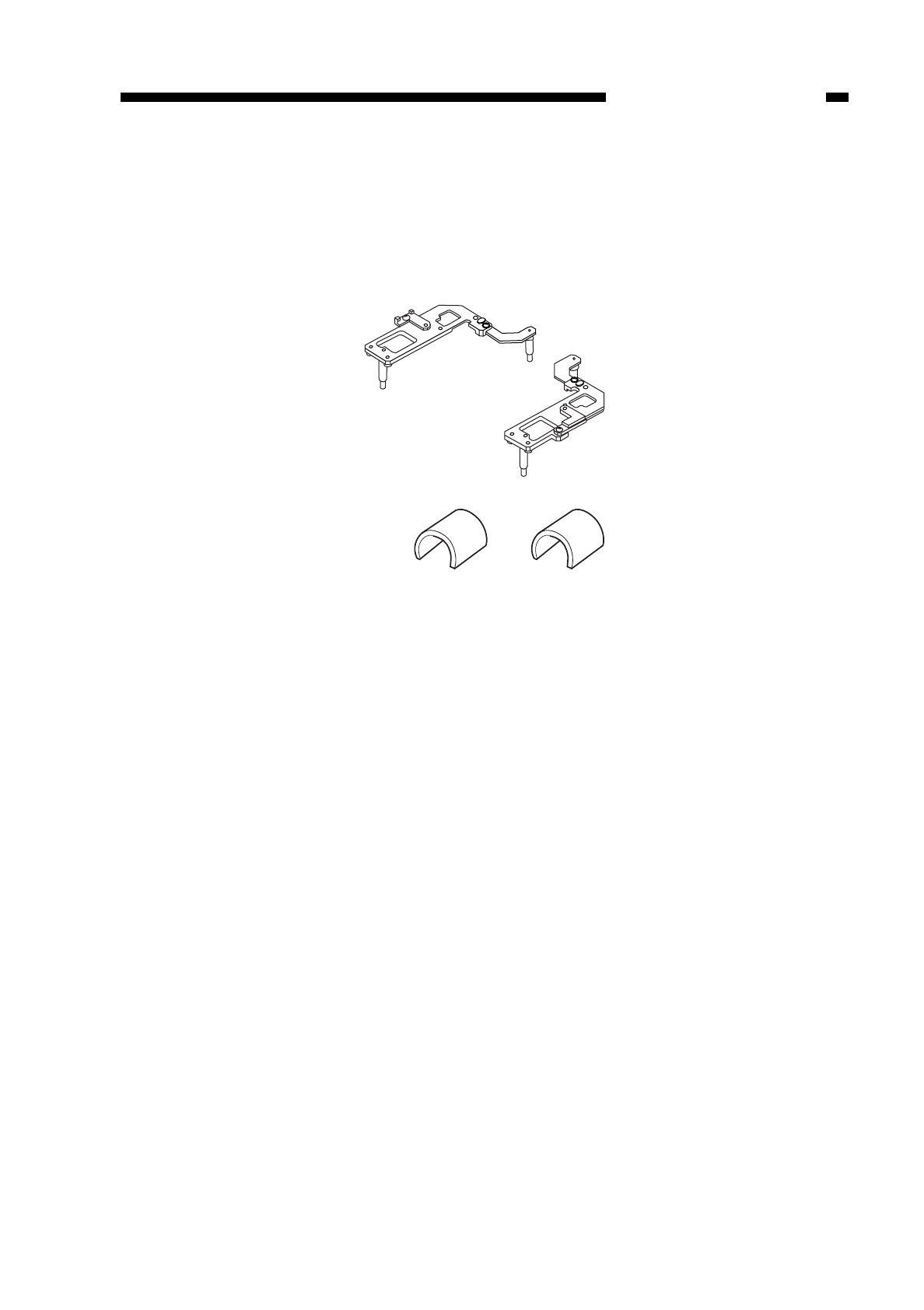
4. Routing the Scanner Cable
Keep the mirror positioning tool (FY9-3009) and pulley clip (FY9-3010) handy when
routing the scanner cable.
Further, if you are using the mirror positioning tool, assemble it in advance by
referring to “3. Assembling the MIrror Positioning Tool.”
Figure 3-409
COPYRIGHT
©
1997 CANON INC. CANON NP6218 REV. 0 MAY 1997 PRINTED IN JAPAN (IMPRIME AU JAPON)
CHAPTER 3 EXPOSURE SYSTEM
3-13
A
A
B
B
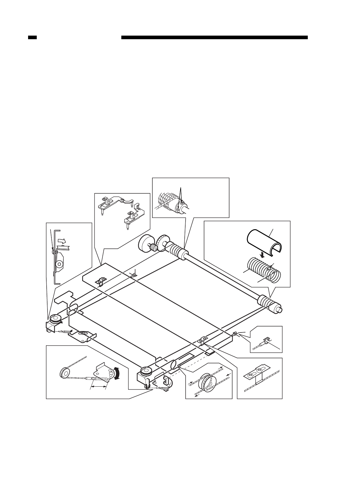
1) Put the steel ball into the hole of the pulley, and wind the cable four times toward the
flange and then nine times in the opposite direction; thereafter, fix it in place using
the pulley clip.
2) As in w, set the mirror positioning tool between the No. 1 and No. 2 mirror mounts.
3) Loosen the screw on the mirror pulley mount as in e; then, temporarily fix the cable
in position on the left stay.
4) Route the cable as shown in the illustration; engage ton the hook on the side plate,
and engage the ion the tension plate on the lens mount.
5) Tighten the screw loosened in e, and fix the cable to the left stay.
6) Loosen the screws on the drive pulley once so that the tension of the scanner cable
is even as in !0; then, tighten it once again.
7) Fix the No. 1 mirror mount and the scanner cable fixing as in !1.
8) Make adjustments so that the length of the cable is 34 ±1 mm as in ousing a ruler.
Figure 3-410
COPYRIGHT
©
1997 CANON INC. CANON NP6218 REV. 0 MAY 1997 PRINTED IN JAPAN (IMPRIME AU JAPON)
CHAPTER 3 EXPOSURE SYSTEM
3-14
Screw
Losen the screw,
and shift.
Re-tighten
the screw.
Set the mirror
positioning tool
Set screws
Loosen the set
screw to free the
totation of the
pulley.
Put the steel ball into
the hole in the
pulley, and wind the
cable nine times
toward the inside
and four times
toward the outside;
then, fit the pulley clip.
Pulley clip
Steel ball
34±1mm
o
y
u
r
!1
t
q
!0
w
e
i
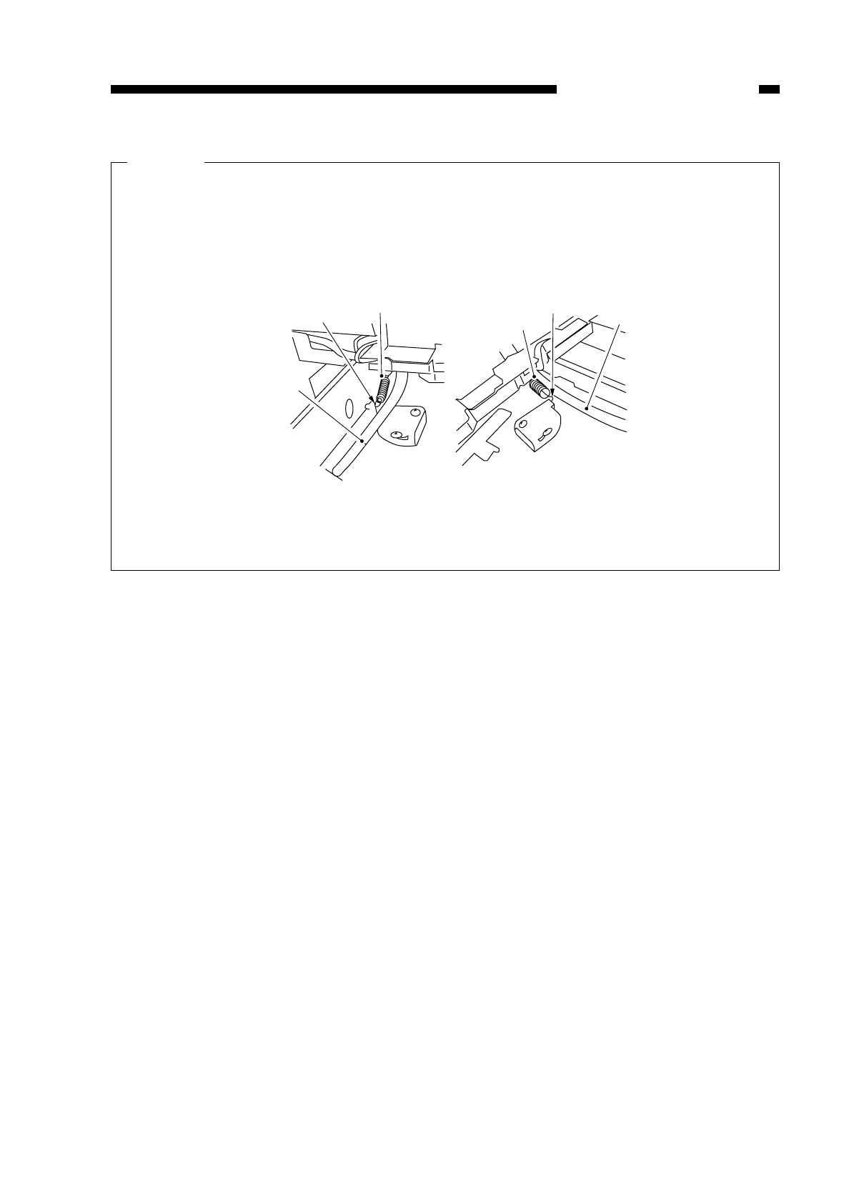
Caution:
When attaching the wire spring, pay attention to the orientation of the spring; see
the diagrams below. If not attached correctly, its hook tip could interfere with the
cable.
Figure 3-411
COPYRIGHT
©
1997 CANON INC. CANON NP6218 REV. 0 MAY 1997 PRINTED IN JAPAN (IMPRIME AU JAPON)
CHAPTER 3 EXPOSURE SYSTEM
3-15
Wirespring
Wirespring
Hook Hook
Cable
Cable
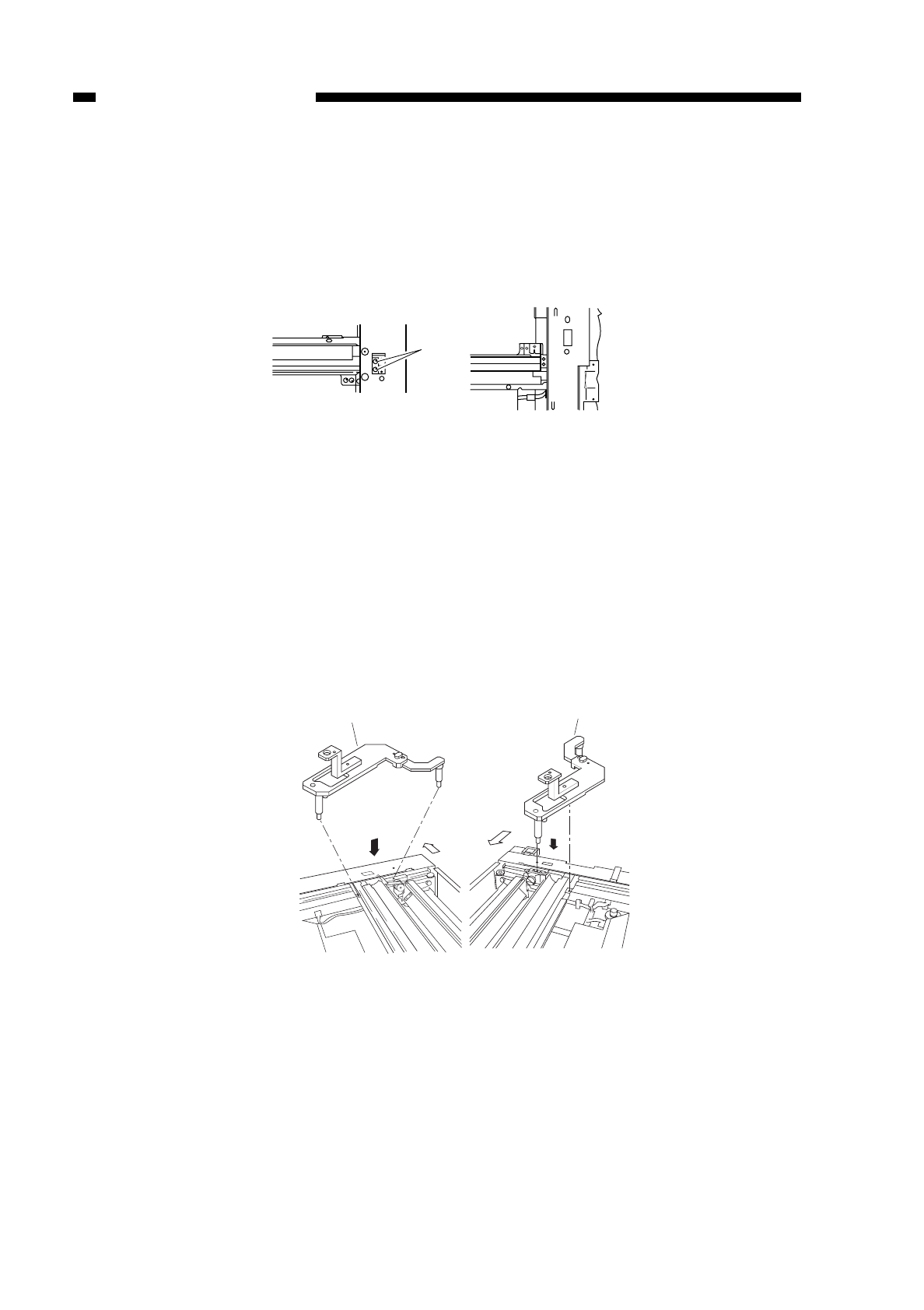
5. Adjusting the Position of the Mirrors (optical length of No. 1, 2, and 3 mirrors)
1) Keep the mirror positioning tool handy.
(See “3. Assembling the Mirror Positioning Tool.”)
2) Move the No. 1 mirror mount toward the front, and align the angular hole in the front
side plate and the cable fixing screw q.
Figure 3-412
3) Loosen the set screw on the pulley.
4) Set the mirror positioning tool wto the No. 1 mirror mount and the No. 2 mirror mount
(both front and rear).
Figure 3-413
COPYRIGHT
©
1997 CANON INC. CANON NP6218 REV. 0 MAY 1997 PRINTED IN JAPAN (IMPRIME AU JAPON)
CHAPTER 3 EXPOSURE SYSTEM
3-16
q
(front) (rear)
(front)
(front)
Mirror positioning tool (front) Mirror positioning tool (rear)
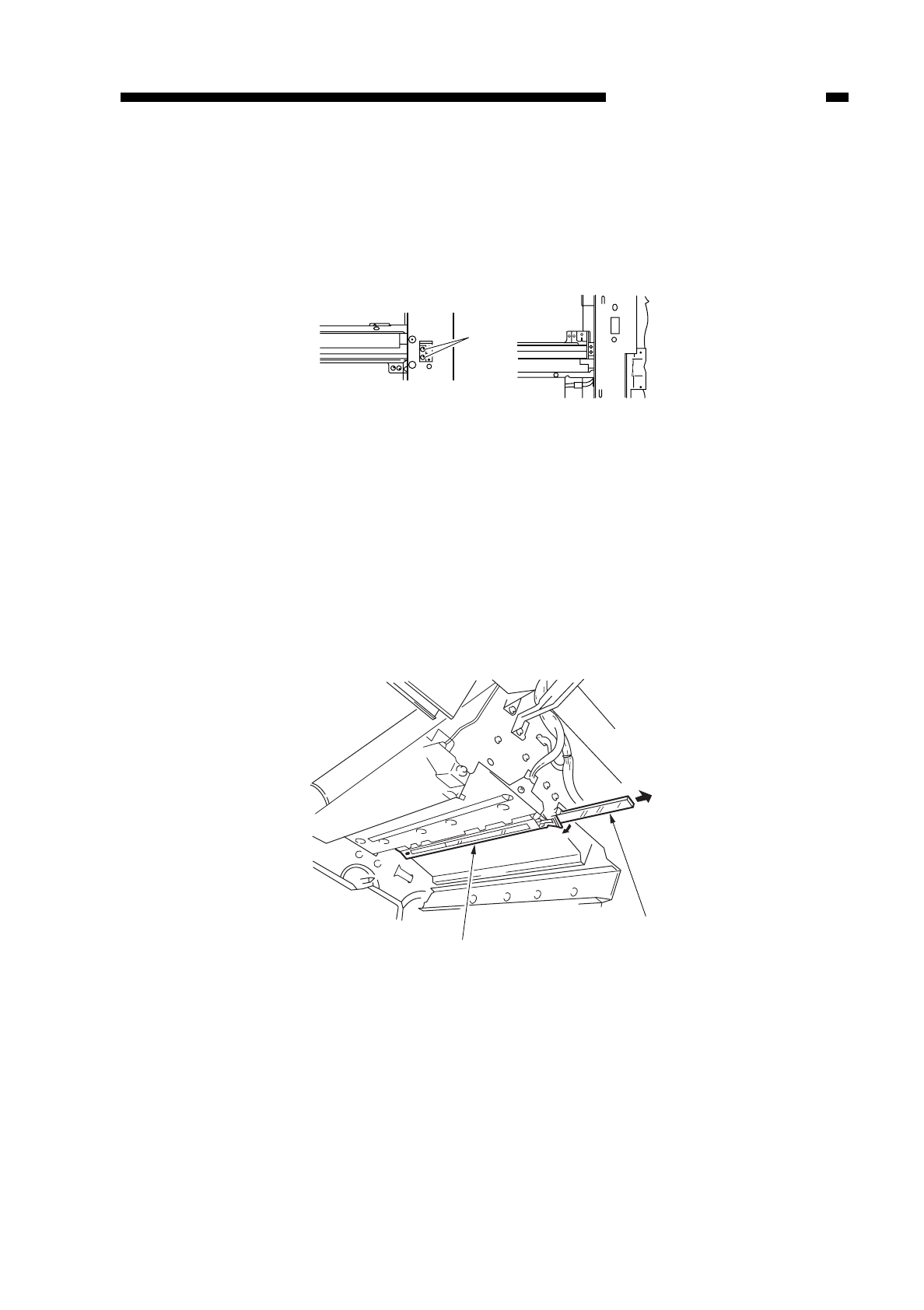
5) Attach the scanner cable fixing to the No. 1 mirror mount using two screws e(both
front and rear).
6) Tighten the screw on the pulley.
7) Detach the tool (FY9-3009).
Figure 3-414
6. Cleaning the Scanner No. 6 Mirror
1) Open the front cover.
2) Open the copier by operating the copier open/close lever.
3) Detach the dust-proofing glass qand dust-proof mirror cover w.
Figure 3-415
4) Clean the No. 6 mirror using a blower brush or lint-free paper moistened with alcohol.
COPYRIGHT
©
1997 CANON INC. CANON NP6218 REV. 0 MAY 1997 PRINTED IN JAPAN (IMPRIME AU JAPON)
CHAPTER 3 EXPOSURE SYSTEM
3-17
e
(front) (rear)
q
w
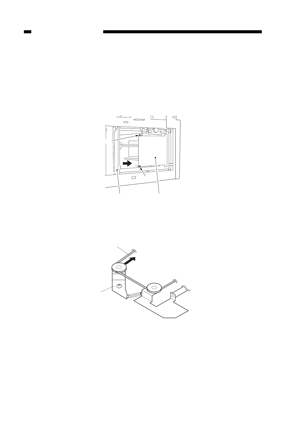
B. Lens Drive Assembly
1. Detaching the Lens Drive Motor
1) Detach the upper rear cover and right glass rerainer.
2) Detach the copyboard glass.
3) Move the No. qmirror assembly 1 to the left.
4) Remove the two screws w, and detach the lens cover e.
Figure 3-416
5) Loosen the tension on the spring r, and detach the cable t.
Figure 3-417
COPYRIGHT
©
1997 CANON INC. CANON NP6218 REV. 0 MAY 1997 PRINTED IN JAPAN (IMPRIME AU JAPON)
CHAPTER 3 EXPOSURE SYSTEM
3-18
qe
w
w
r
t
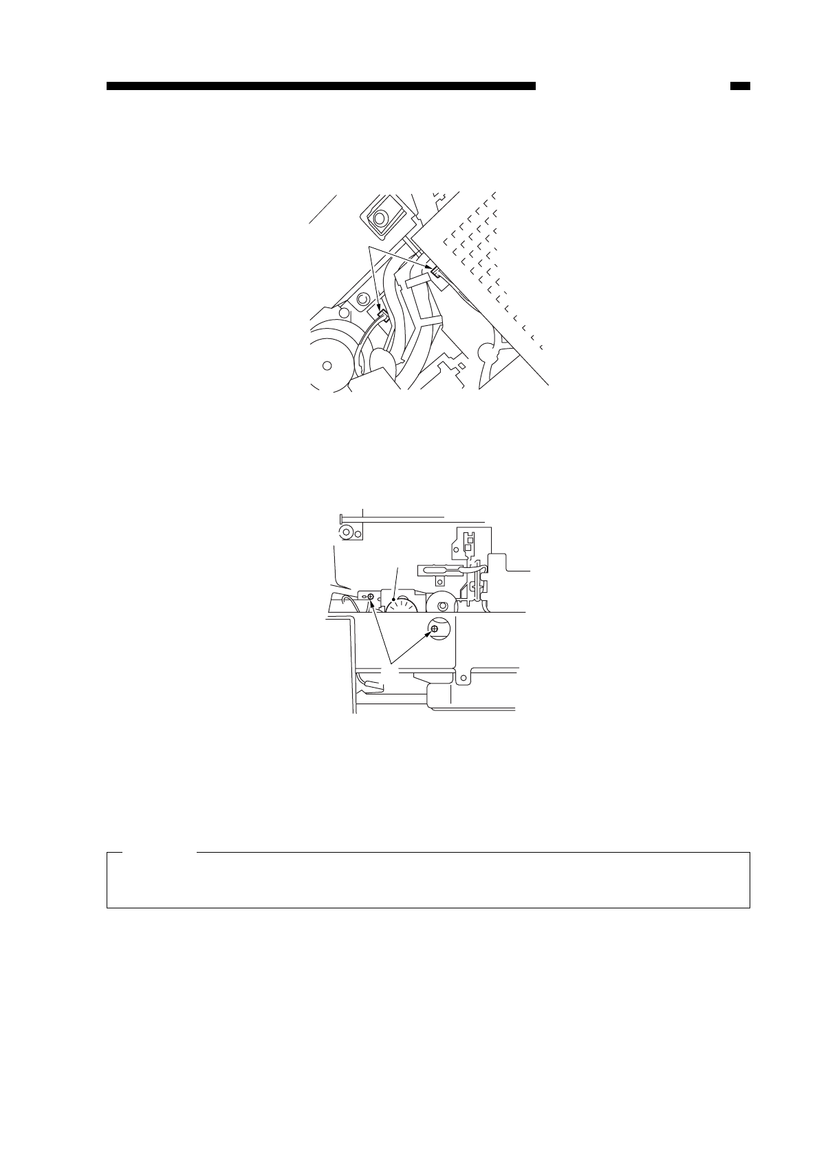
6) Disconnect the two connectors yfrom the copier’s rear.
Figure 3-418
7) Remove the two screws u, and detach the lens drive unit i.
Figure 3-419
8) Remove the two screws, and disconnect the connector !0; then, detach the lens
motor !1.
Caution:
Disconnect the connector !0 first before removing the screw o; otherwise, the
harness and driver will come into contact with each other.
COPYRIGHT
©
1997 CANON INC. CANON NP6218 REV. 0 MAY 1997 PRINTED IN JAPAN (IMPRIME AU JAPON)
CHAPTER 3 EXPOSURE SYSTEM
3-19
y
i
u
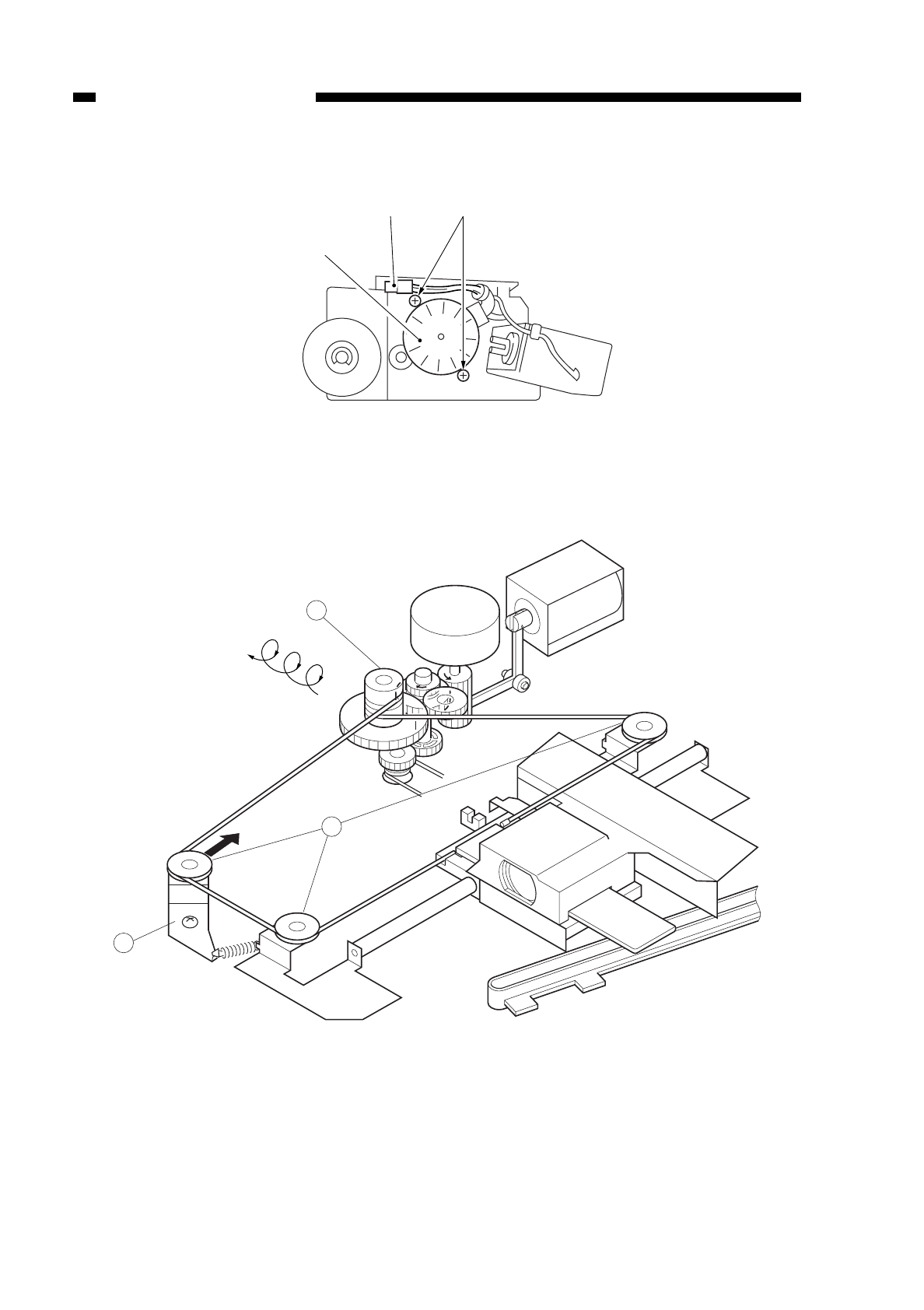
Figure 3-420
2. Routing the Lens Cable
Figure 3-421 Lens Drive Assembly
1) Attach the lens cable to each pulley qwhile winding it around the lens pulley was
indicated in Figure 3-421.
2) Move the tension pulley eto hook the cable.
COPYRIGHT
©
1997 CANON INC. CANON NP6218 REV. 0 MAY 1997 PRINTED IN JAPAN (IMPRIME AU JAPON)
CHAPTER 3 EXPOSURE SYSTEM
3-20
!1
o!0
2
1
SL
Turn clockwise
three times.
3
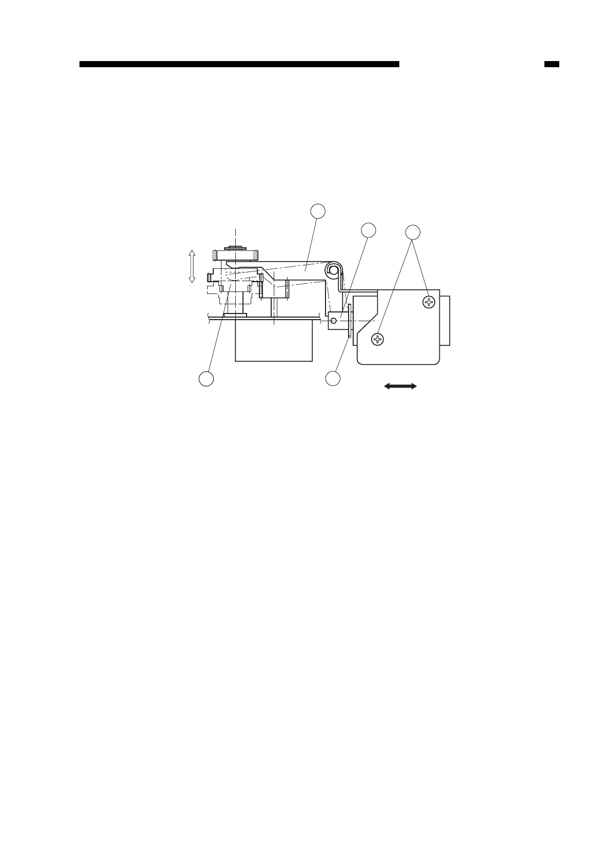
3. Adjusting the Position of the Change Solenoid
Make adjustments by loosening the two screws tso that the gear ris moved fully
in the direction of b by the arm ewhen the steel core qof the solenoid is fully pushed
in the direction of B by a finger, i.e., when the E-ring wcomes into contact with the
solenoid.
Figure 3-422
COPYRIGHT
©
1997 CANON INC. CANON NP6218 REV. 0 MAY 1997 PRINTED IN JAPAN (IMPRIME AU JAPON)
CHAPTER 3 EXPOSURE SYSTEM
3-21
a
b
B
A
5
44 2
1
3

COPYRIGHT
©
1997 CANON INC. CANON NP6218 REV. 0 MAR. 1997 PRINTED IN JAPAN (IMPRIME AU JAPON)
CHAPTER 3 EXPOSURE SYSTEM
3-22

COPYRIGHT
©
1997 CANON INC. CANON NP6218 REV. 0 MAY 1997 PRINTED IN JAPAN (IMPRIME AU JAPON)
CHAPTER 4
IMAGE FORMATION SYSTEM
I. PROCESSES .....................................4-1
A. Outline ...........................................4-1
B. Basic Sequence of Operations
(image formation system)..............4-3
C. Controlling the Scanning Lamp .....4-4
D. Controlling the Primary Charging
Roller Bias .....................................4-10
E. Controlling the Transfer Roller
Bias................................................4-13
F. Controlling the Static Eliminator
Bias................................................4-16
G. Controlling Blank Exposure...........4-18
H. Controlling the Primary Corona
Roller Cleaning Mechanism ..........4-20
I. Releasing the Transfer Roller........4-21
II. DEVELOPING ASSEMBLY AND
CLEANING ASSEMBLY .....................4-22
A. Outline ...........................................4-22
B. Controlling the Toner Level
Detection .......................................4-23
C. Controlling the Development
Bias................................................4-25
D. Automatic Control of Copy
Density...........................................4-27
III. DISASSEMBLY AND ASSEMBLY ......4-30
A. Illumination Assembly....................4-30
B. Drum Unit ......................................4-39
C. Primary Corona Assembly.............4-41
D. Transfer Charging Assembly .........4-44
E. Developing System........................4-47
This chapter discusses the principles of how images are formed. It also explains the timing at
which the various units involved in image formation are operated, and shows how they may be
disassembled/assembled and adjusted.
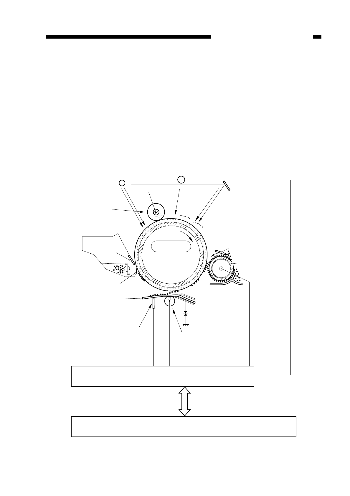
I. PROCESSES
A. Outline
Figure 4-101 shows the basic construction of the copier’s image formation system,
whose main functions are as follows:
• scanning lamp control
• primary charging control
• transfer charging control
• separation static eliminator control
• developing bias control
• blank exposure lamp control
Figure 4-101
COPYRIGHT
©
1997 CANON INC. CANON NP6218 REV. 0 MAY 1997 PRINTED IN JAPAN (IMPRIME AU JAPON)
CHAPTER 4 IMAGE FORMATION SYSTEM
4-1
--
-
-
-
-
-
-
-
--
----- -
-
-
-
Pre-exposure lamp
+
+
+
+
Scanning lamp
Blade
Cleaning blade
Transfer corona
assembly
Paper
Composite Power Supply PCB
DC controller PCB
Light area
Optical
image
+
+++++
+
+
+
++
+
+
+
+
+
+
+
+
+
+
+
+
+
+
+
++
Primary corona assembly
Dark
area
Developing
cylinder
Photosensitive
drum
Sttic eliminator
Blade
Scoop-up sheet
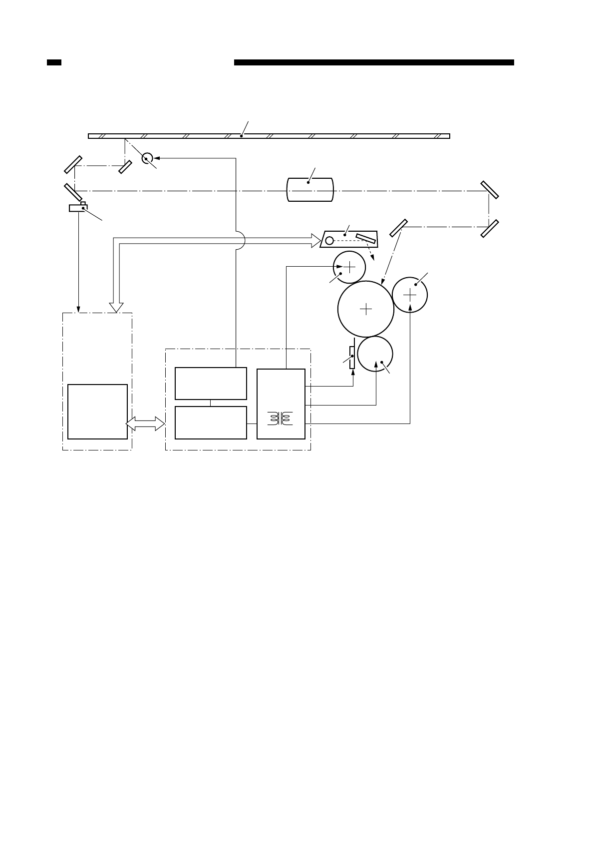
Figure 4-102
COPYRIGHT
©
1997 CANON INC. CANON NP6218 REV. 0 MAY 1997 PRINTED IN JAPAN (IMPRIME AU JAPON)
CHAPTER 4 IMAGE FORMATION SYSTEM
4-2
DC controller
PCB
Microprocessor
(Q301)
AE sensor
Scanning lamp
Copyboard glass
Lens
Blank exposure unit
Primary
charging
roller
Composite power
supply
Scanning lamp
ON control
circuit assembly
Microprocessor
(Q512)
High-voltage
circuit
assembly
T101
Static
eliminator
Developing cylinder
Transfer
roller
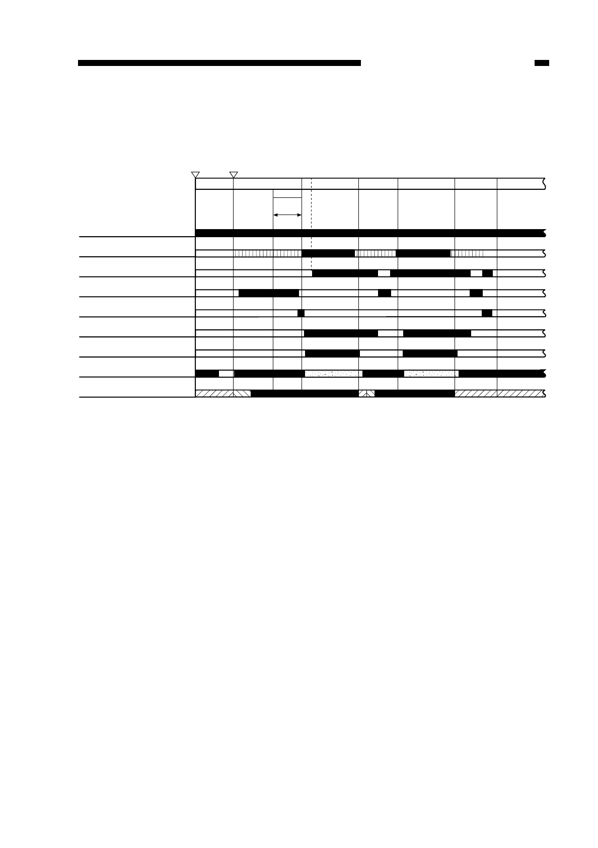
B. Basic Sequence of Operations (image formation system)
1 AE only.
2 half pre-heating control.
3 full pre-heating control.
4 ON pre-heating control.
Figure 4-103
COPYRIGHT
©
1997 CANON INC. CANON NP6218 REV. 0 MAY 1997 PRINTED IN JAPAN (IMPRIME AU JAPON)
CHAPTER 4 IMAGE FORMATION SYSTEM
4-3
Main motor/Pre-exposure lamp
Primary charging
Transfer charging
Transfer cleaning
Reference bias (ATVC)
Separation static eliminator
Developing bias AC component
Developing bias DC component
Scanning lamp
Power switch
ON Copy Start key
ON
AER
*1
STBY INTR SCFW SCRV SCFW SCRV LSTR
*2 *3
*4
*2 *3
*4
*2
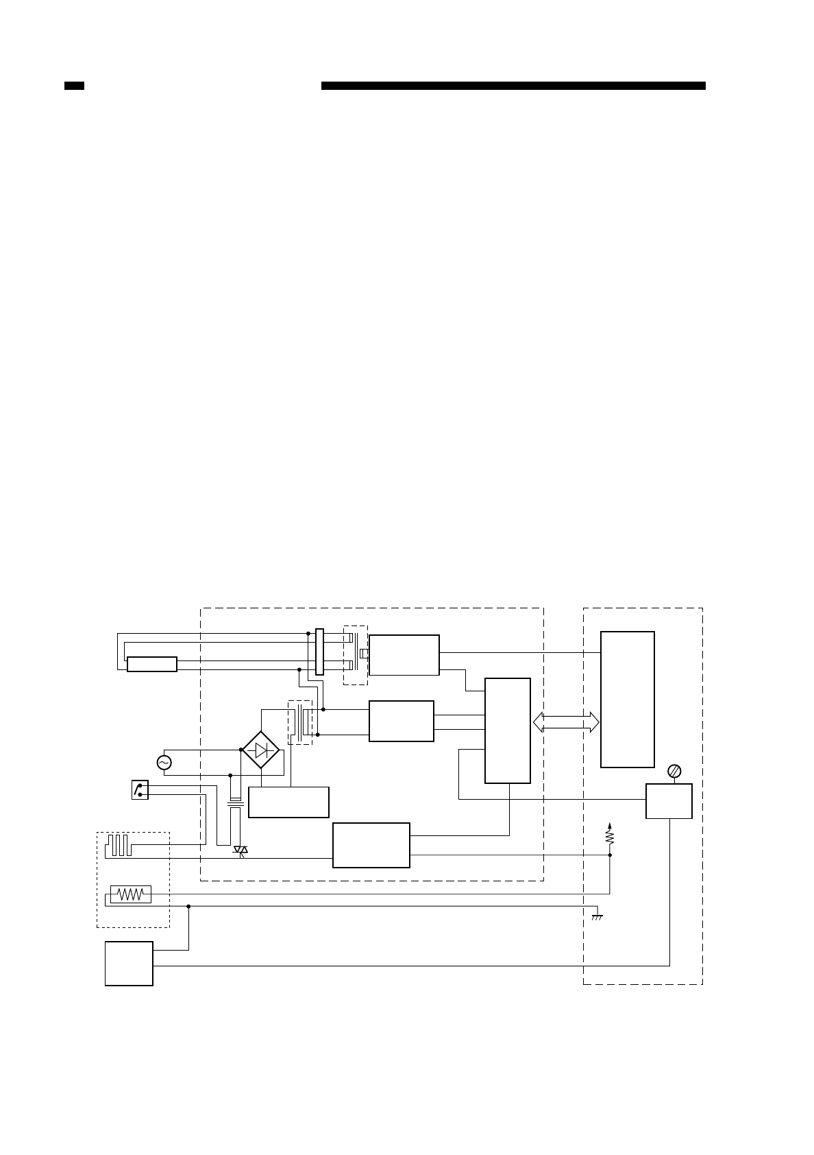
C. Controlling the Scanning Lamp
1. Outline
Figure 4-104 shows the circuit that controls the scanning lamp; the circuit has the
following functions:
• turns on and off the scanning lamp.
• controls scanning lamp pre-heating operation.
• controls scanning lamp intensity.
• controls the scanning lamp heater.
The copier’s scanning lamp is a fluorescent lamp.
In general, a fluorescent lamp is low in intensity immediately after power-on,
gradually increasing in intensity as time passes, without control; in particular, it takes a
long time before the intensity stabilizes in a low temperature environment.
If the ambient temperature drops below 15°C, the copier may enter and remain in
wait state before a specific intensity can be obtained. To prevent this from occurring, a
fluorescent lamp is provided for installation in low temperature environments.
To ensure that the lamp exposes an original at a stable intensity, a fluorescent lamp
adjusting sensor is used to monitor the intensity of the lamp during copying operation,
thereby controlling it to a specific value.
In addition, half pre-heating is executed between power-on and a press on the Copy
Start key so as to ensure that the lamp reaches its optimum intensity within a short
period of time after a press on the Copy Start key; thereafter, full pre-heating is
performed. (See Figure 4-105.)
Figure 4-104
COPYRIGHT
©
1997 CANON INC. CANON NP6218 REV. 0 MAY 1997 PRINTED IN JAPAN (IMPRIME AU JAPON)
CHAPTER 4 IMAGE FORMATION SYSTEM
4-4
(FL1)
J205 T401
Scanning lamp
Composite power
supply PCB
Fluorescent
lamp pre-
heating circuit
FLPRHT*
32KHzCLC
T101
T103
DC controller PCB
Micro-
processor
(Q301)
SW2
Fluorescent lamp
heater switch 5V
Fluorescent lamp
heater
Fluorescent lamp
thermistor
J701-1
(H2)
(TH3)
J202-1
-2
Fluores
cent lamp
intensity
sensor
-3
Main switch
Q108
FLTHON
FL ON
MPWM
FLS
Fluorescent
lamp drive
circuit
FLHTOFF*
FLTH
Micro-
processor
(Q512)
J211-3
J302-9
J211-9
FLTH J317-1
-2
-4
VR301
Reversal
amplifier
circuit
Fluorescent lamp
heater
control circuit
Main transformer
(T101) drive circuit
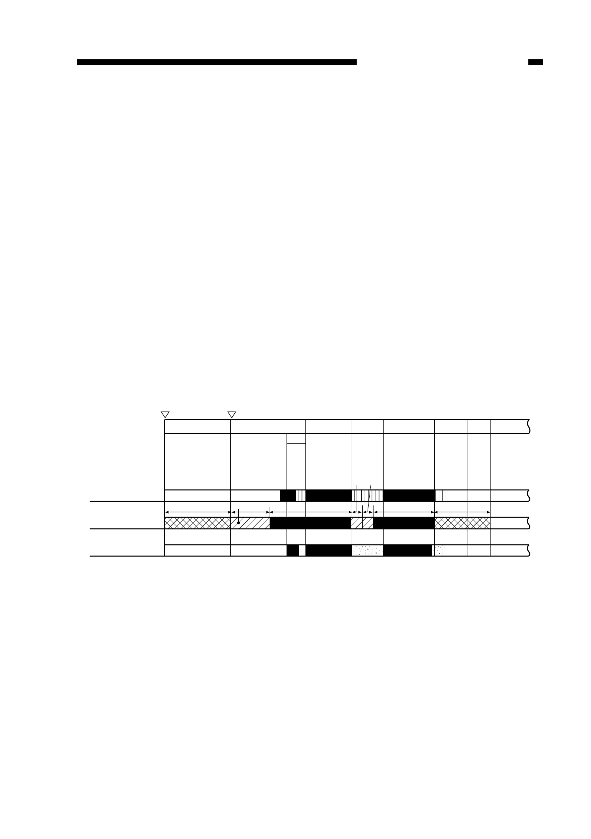
2. Turning On and Off the Scanning Lamp
The microprocessor (Q301) on the DC controller PCB exerts control so that the
microprocessor (Q512) on the composite power supply PCB generates the scanning
lamp ON signal (FLON)=0 (pulse signal, 1 kHz). At the time, the fluorescent lamp drive
circuit applies the output of the secondary side of the transformer (T101) to the scanning
lamp (FL1), thereby allowing current to flow through the scanning lamp and causing the
lamp to turn on at a high frequency (about 120 kHz).
3. Pre-Heating Control (scanning lamp)
The copier exerts four modes of control; namely, half pre-heating, full pre-heating,
ON pre-heating I, and ON pre-heating II.
These modes of control are executed by the microprocessor (Q301) on the DC
controller by varying the duty ratio of the fluorescent lamp pre-heat signal (FLPRHT;
pulse) of 5 kHz to suit each pre-heat control mode sent to each scanning lamp pre-heat
circuit. Based on the signal, the scanning lamp pre-heat circuit modulates the amplitude
of the signal (32 kHz); in response, the secondary side of the transformer (T401) turns
on to allow the fluorescent lamp pre-heat current to flow, thereby starting pre-heating
operation. (For the sequence of operations, see Figure 4-105.)
4. Sequence of Operations (scanning lamp pre-heating control; AE, A4,
continuous, 2 copies)
1 half pre-heating control.
2 full pre-heating control.
3 ON pre-heating I or II control.
Figure 4-105
COPYRIGHT
©
1997 CANON INC. CANON NP6218 REV. 0 MAY 1997 PRINTED IN JAPAN (IMPRIME AU JAPON)
CHAPTER 4 IMAGE FORMATION SYSTEM
4-5
STBY
Power switch
ON Copy Start key
ON
AER
*1*3 *3
*2
*1
*1 *2
INTR SCFW SCRV SCFW SCRV LSTR STBY
Scanner
Scanning lamp
Primary charging
1.5 sec
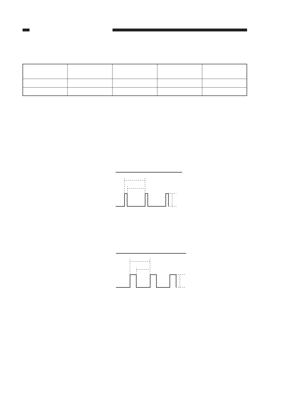
■Input Signals from the DC Controller to the Composite Power Supply PCB
*ON duty ratio of FLOW signal (in relation to 1kHz):
40% or more ................................ON I
less than 40% ..............................ON II
Table 4-101
■Half Pre-Heating Control (between press on Power switch and press on Copy Start
key; part of scanner reverse travel)
Figure 4-106
■Full Pre-Heating Control (initial rotation, last rotation, part of scanner reverse travel)
Figure 4-107
COPYRIGHT
©
1997 CANON INC. CANON NP6218 REV. 0 MAY 1997 PRINTED IN JAPAN (IMPRIME AU JAPON)
CHAPTER 4 IMAGE FORMATION SYSTEM
4-6
FLON signal
FLPRHT signal
OFF
5KHz
5V
0V
25.9%
Duty ratio (5 kHz)
Filament voltage
Half preheating
25.9 %
2.5Vrms
Full preheating
60 %
4.5Vrms
Fluorescent lamp
ON I*
44.4 %
3.6Vrms
Fluorescent lamp
ON II*
55 %
4.1Vrms
FLON signal
FLPRHT signal
OFF
5KHz
5V
0V
60%
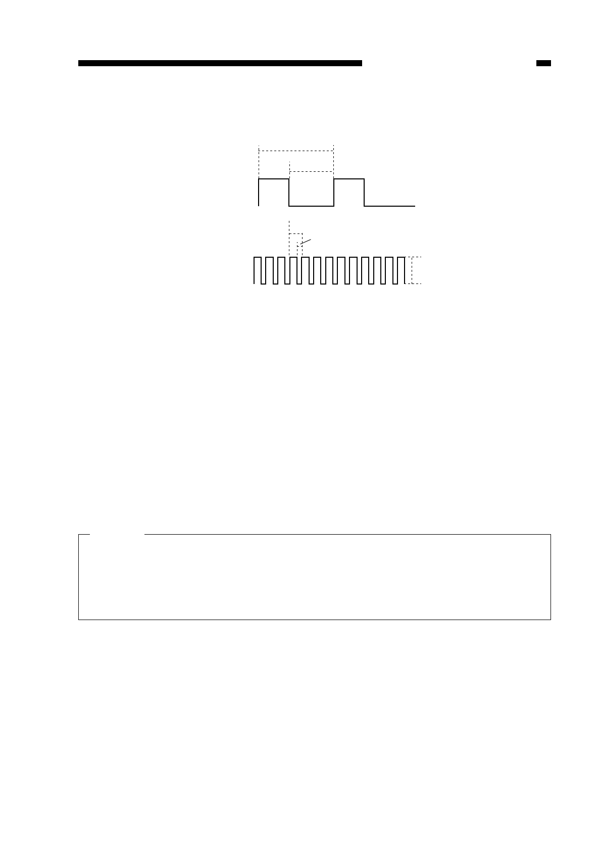
■Scanning Lamp ON Pre-Heating Control (during copying operation I)
Figure 4-108
5. Controlling the Intensity of the Scanning Lamp (FL1)
• If the intensity of the fluorescent lamp is too low at power-on,
The starting power of the intensity adjustment sensor lowers, and the fluorescent lamp
intensity adjustment signal (FLS) of the amplifier circuit on the DC controller increases.
In response to the signal, the microprocessor (Q512) on the composite power supply
PCB reduces the duty ratio, thereby increasing the ON time of the FLON signal.
The current flows through the filament of the fluorescent lamp when both the MPWM
signal (150 kHz) and the FLON signal (1 kHz) are on.
• If the intensity of the fluorescent lamp is too high at power-on,
The starting power of the intensity adjustment sensor rises, and the fluorescent lamp
intensity adjustment signal (FLS) of the amplifier circuit on the DC controller PCB
decreases. In response to the signal, the microprocessor (Q512) on the composite
PCB increases the duty ratio, thereby decreasing the ON time of the FLON signal.
Caution:
Gain Adjustment for the Intensity Adjustment Sensor (VR301)
If you replaced the intensity adjustment sensor or the scanning lamp (fluorescent
lamp, FL1), or the DC controller PCB, you must always perform gain adjustment for
the intensity adjustment sensor using VR301 on the DC controller PCB. (See the p.
10-10.)
COPYRIGHT
©
1997 CANON INC. CANON NP6218 REV. 0 MAY 1997 PRINTED IN JAPAN (IMPRIME AU JAPON)
CHAPTER 4 IMAGE FORMATION SYSTEM
4-7
FLON signal
FLPRHT signal
ON ON
5KHz
1KHz
5V
0V
44.4%
OFF OFF
40% or more
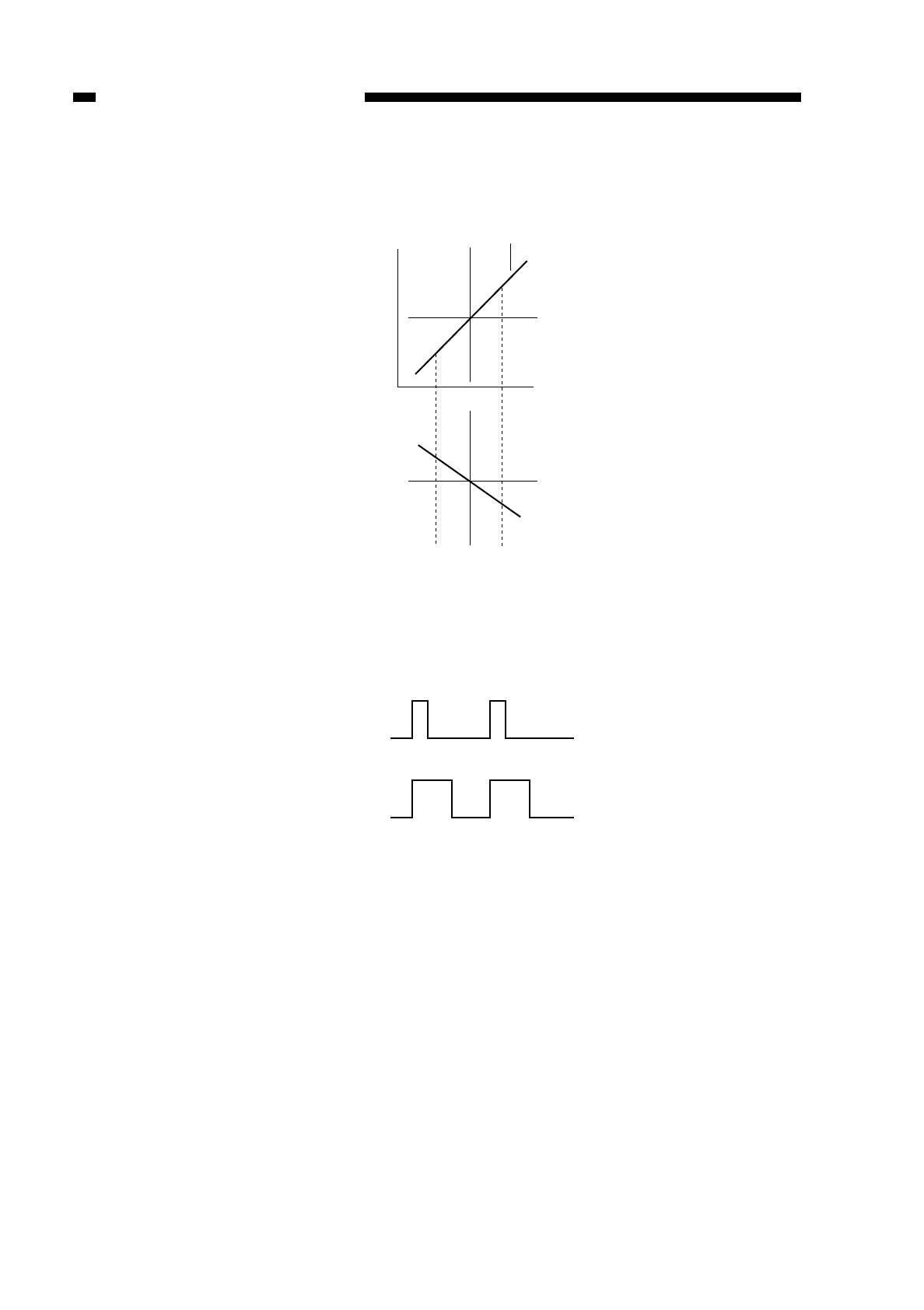
■Input to the Reversal Amplifier Circuit (if the intensity increased gradually)
Figure 4-109
■Changes in the Duty Ratio of the FLON signal
Figure 4-110
6. Controlling the Fluorescent Lamp Heater
As the temperature around the scanner increases, the resistance of the fluorescent
lamp thermistor (TH3) lowers, thereby lowering the voltage of the fluorescent lamp
thermal signal (FLTH). Based on the voltage, the fluorescent lamp heater control circuit
on the composite power supply PCB turns on and off the fluorescent lamp heater drive
signal (FLTHON).
You can force the fluorescent heater off by turning off the scanning lamp (fluorescent
lamp) heater switch (SW2) during the months in which the heater is not needed.
COPYRIGHT
©
1997 CANON INC. CANON NP6218 REV. 0 MAY 1997 PRINTED IN JAPAN (IMPRIME AU JAPON)
CHAPTER 4 IMAGE FORMATION SYSTEM
4-8
Reference voltage
(4V)
Reference voltage
(4V)
Voltage (V)
Input from intensity
adjustment sensor
Lighter
Darker
Time (t)
"C" "D"
FLON signal 'C'
FLON signal 'D'
OFF
OFF
ON
ON

COPYRIGHT
©
1997 CANON INC. CANON NP6218 REV. 0 MAY 1997 PRINTED IN JAPAN (IMPRIME AU JAPON)
CHAPTER 4 IMAGE FORMATION SYSTEM
4-9
7. Fluorescent Lamp Automatic
Correction Control (ALVC control)
The copier executes control (ALVC control) that automatically corrects the scanning
lamp on voltage to make up for the change that otherwise could occur as a result of
deterioration of the photosensitive drum.
8. Fluorescent Lamp Protection Mechanism
If the fluorescent lamp fails or flickers continuously after copying is started, the
microprocessor on the DC controller increases the application voltage to turn on the
lamp properly.
This, however, imposes an excessive voltage to the fluorescent lamp, speeding up its
deterioration. To prevent such a problem, the DC controller turns off the power when an
error in the application voltage is detected on the composite power supply PCB.
Reference:
If the same problem occurs when the power is returned, the fluorescent lamp may
be faulty. Try replacing it.
Warning:
Do not execute operations that turn on the fluorescent lamp (coying, service mode)
without installing the fluorescend lamp.
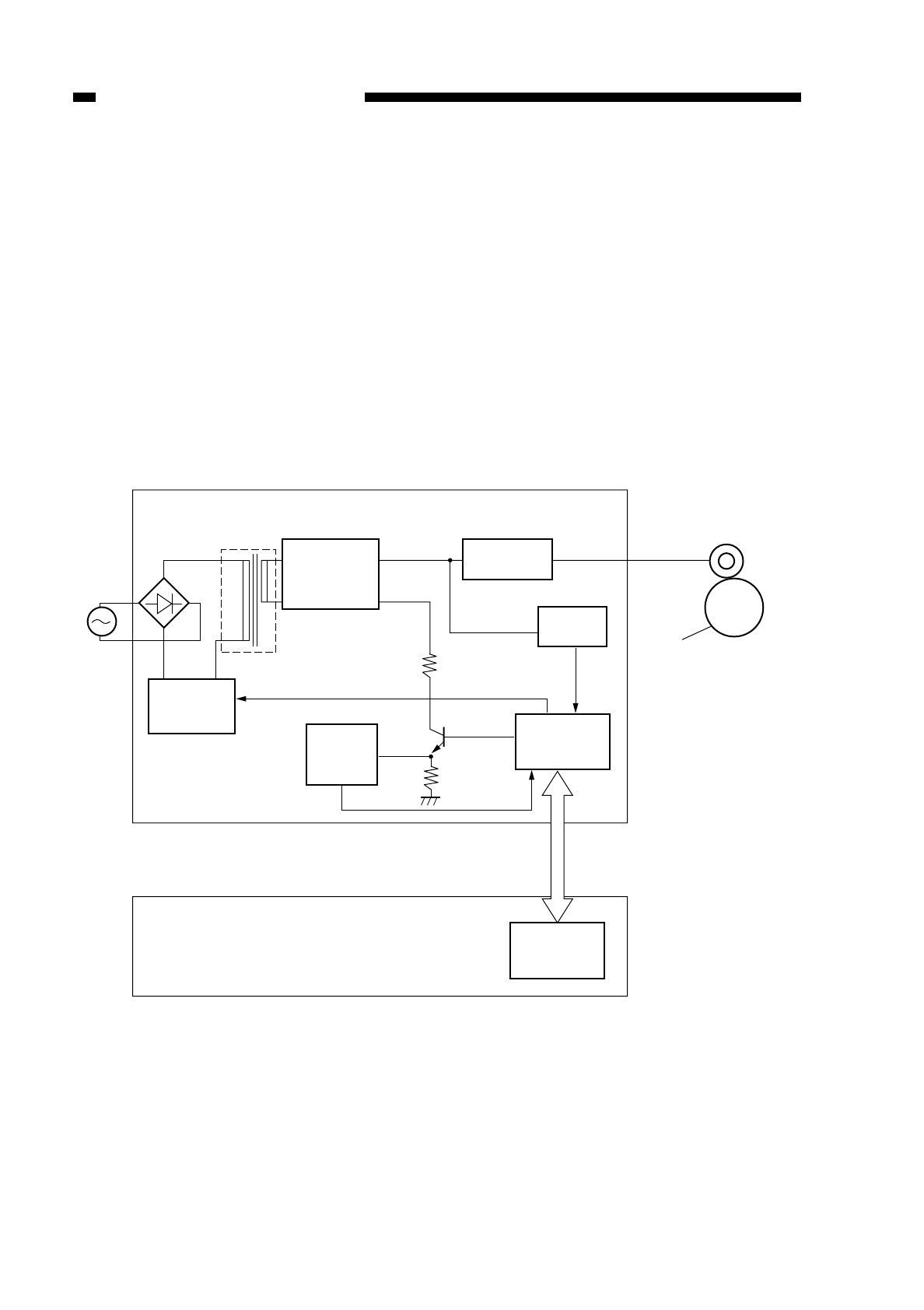
D. Controlling the Primary Charging Roller Bias
1. Outline
Figure 4-111 shows the circuit that controls the voltage applied to the primary
charging roller; the circuit has the following functions:
• turns on and off the primary charging roller bias.
• controls the primary charging roller bias to a constant voltage.
• switches the application voltage level for the primary charging roller bias.
• switches the application voltage level for the primary charging roller bias.
• corrects the scanning lamp on voltage level
The main transformer (T101) is driven by the drive signal (MPWM) generated by the
main transformer (T101).
The main transformer (T101), further, is used also as the high voltage transformer for
the DC power supply and others in addition to providing the above functions.
Figure 4-111
COPYRIGHT
©
1997 CANON INC. CANON NP6218 REV. 0 MAY 1997 PRINTED IN JAPAN (IMPRIME AU JAPON)
CHAPTER 4 IMAGE FORMATION SYSTEM
4-10
MPWM
PDCS
Composite power supply PCB
Main transformer
T101
Main transformer
(T101)
drive circuit
Rectifier circuit
Current
detection
circuit
Filter circuit
Voltage
detection
circuit
Micro-
processor
Q512
Q301 (Master)
Micro-
processor
PDC-PWM
PCS
Primary charging roller
Photosensitive drum
DC controller PCB

2. Turning On and Off the Primary Charging Roller Bias
The microprocessor (Q512) on the composite power supply PCB generates the
PDCPWN signal (pulse signal) under the control of the microprocessor master (Q301)
on the DC controller PCB. In response to the signal, the secondary side of the main
transformer (T101) turns on to apply a primary charging roller bias.
The main transformer (T101) is driven by the drive signal (MPWM) from the
microprocessor (Q512). The main transformer (T101) is also used as the high-voltage
transformer for the DC power supply and other loads.
3. Controlling the Primary Charging Roller Bias to a Constant Voltage
While a bias voltage is being applied to the primary charging roller, the
microprocessor (Q512) on the composite power supply PCB reads the PDCS signal
(analog signal) from the voltage detection circuit to control the PDCPWM signal so that
the output voltage is maintained at a specific level.
4. Switching the Primary Charging Roller Bias Application Voltage Level
The copier applies a cleaning bias to the transfer roller during initial rotation (INT),
while the scanner is moving in reverse (SCRV), and during last rotation, thereby cleaning
the transfer charging roller. (See p. 4-21.)
To enhance the result of cleaning by the cleaning bias and to prevent drum memory
caused by the cleaning bias, a cleaning primary charging roller bias is applied during
initial rotation and while the scanner is moving in reverse.
COPYRIGHT
©
1997 CANON INC. CANON NP6218 REV. 0 MAY 1997 PRINTED IN JAPAN (IMPRIME AU JAPON)
CHAPTER 4 IMAGE FORMATION SYSTEM
4-11
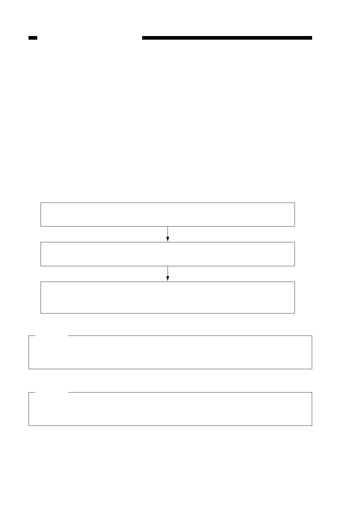
5. Application Voltage Level (APVC) for the Primary Charging Roller and
Scanning Lamp On Voltage Level Automatic Correction
Changes in the static latent image could cause the quality of copies; such changes,
in turn, may be attributed to the following factors:
• changes in the drum sensitivity
• changes in the charge volume of the primary charging roller.
These changes occur as a result of changes in the environment in which the copier
is installed (temperature, humidity), deterioration of parts, or wear and dirt on parts.
In the case of the copier, the light potential (VL) and dark potential (VD) tend to
increase, and the primary charging roller bias application voltage level is corrected
(APVC control) to compensate for possible problems while at the same time executing
scanning lamp on voltage level correction (ALVC control); specifically, the control serves
to ensure constant light potential (VL) and dark potential (VD).
See the following for the flow of operations that occur after the power is switched on
and during initial rotation:
• Flow
A constant voltage of about –1.46 kV is applied to the primary charging roller
for about 1.5 sec.
The current at the time is measured by the current detection circuit, and the
result is sent to the microprocessor (Q512).
The microprocessor (Q512), in turn, sends the result to the microprocessor
(Q301) on the DC controller, which determines the application voltage for
the primary charging roller bias based on the input.
Caution:
You must store the APVC value recorded on the label attached to the composite
power supply PCB in service mode whenever you have replaced the composite
power supply PCB. (See p. 10-102.)
Caution:
You must enter the APVC correction voltage setting recorded on the label attached
to the front of the drum unit whenever you have replaced the drum unit. (See p. 10-
102.)
COPYRIGHT
©
1997 CANON INC. CANON NP6218 REV. 0 MAY 1997 PRINTED IN JAPAN (IMPRIME AU JAPON)
CHAPTER 4 IMAGE FORMATION SYSTEM
4-12
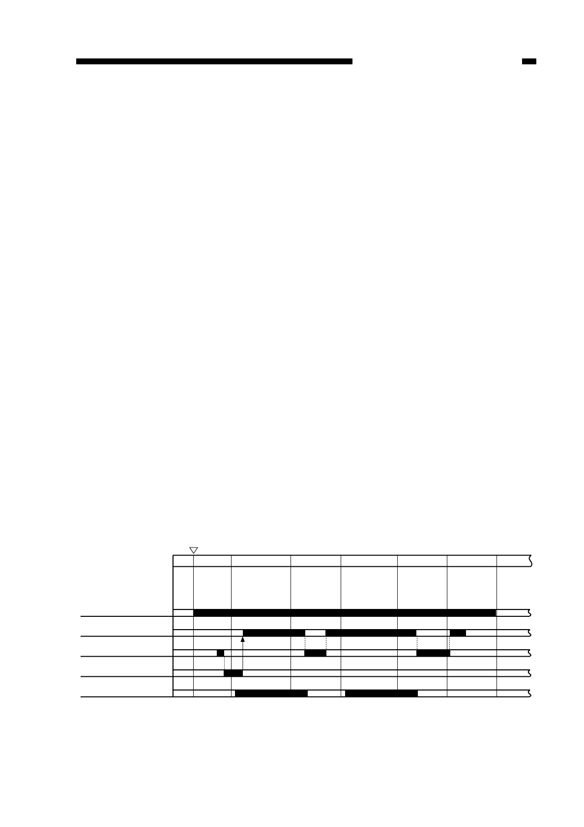
E. Controlling the Transfer Roller Bias
1. Outline
The copier uses a direct transfer method by a roller to transfer images to paper. For
this reason, its bias control differs from that of conventional copiers, which transfer
images by corona charging.
The following three types of transfer roller bias are used; go through the
descriptions for the function and output timing of each.
a. Transfer Bias
This bias corresponds to the transfer bias of conventional copiers, and is a negative
voltage (constant voltage, –3.5 kV to –6.0 kVDC).
b. Cleaning Bias
Since the copier uses a direct transfer method, jams could cause toner on the
photosensitive drum to deposit itself on the transfer roller.
To remove such deposits of toner, the copier applies a positive voltage (constant
voltage, DC) at the following timing, thereby returning the toner from the transfer roller to
the photosensitive drum.
Cleaning Bias Output Timing
• during initial rotation after a press on the Copy Start key
• while the scanner is moving in reverse (certain period)
• during last rotation (certain period)
c. Reference Bias (ATVC)
Changes in the environment or deterioration of the transfer roller can affect the
resistance of the transfer roller, ultimately affecting the transfer efficiency.
To limit the changes in the image quality brought about by such changes in the
transfer efficiency, the copier corrects the application voltage level of the transfer bias.
The transfer ATVC bias (constant current, –10 µA DC) is the bias applied to
determine the correction value each time the Start button is pressed.
Figure 4-112
COPYRIGHT
©
1997 CANON INC. CANON NP6218 REV. 0 MAY 1997 PRINTED IN JAPAN (IMPRIME AU JAPON)
CHAPTER 4 IMAGE FORMATION SYSTEM
4-13
INTR
Copy Start key
ON
Main motor (M1)
Transfer bias
Cleaning bias (+)
Reference bias (ATVC)
Static eliminator bias
SCFW SCRV SCFW SCRV LSTR STRT
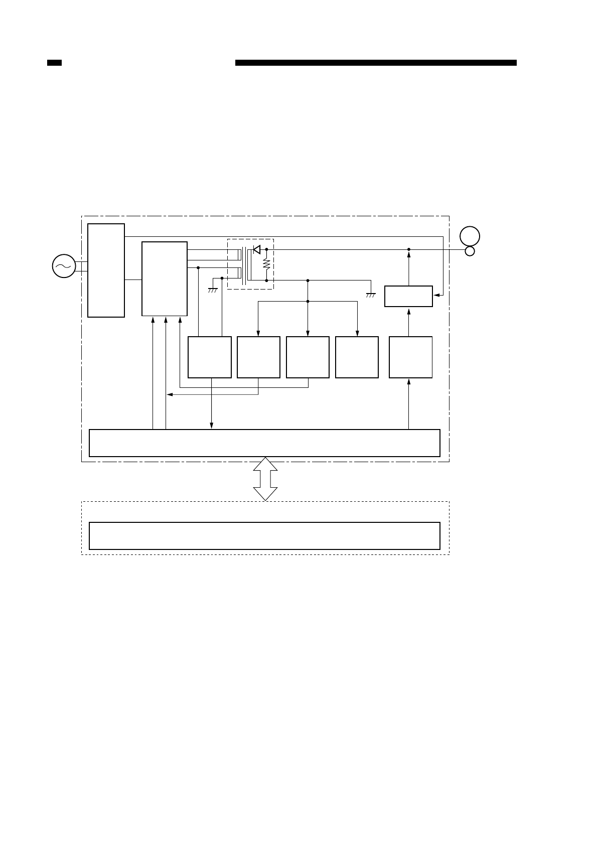
Figure 4-113 shows the circuit used to control the foregoing three types of bias; the
circuit has the following functions:
• turns on and off the transfer roller bias
• controls the transfer bias to a constant voltage
• controls the correction of the transfer bias voltage level
Figure 4-113
COPYRIGHT
©
1997 CANON INC. CANON NP6218 REV. 0 MAY 1997 PRINTED IN JAPAN (IMPRIME AU JAPON)
CHAPTER 4 IMAGE FORMATION SYSTEM
4-14
DC power
supply
assembly
24V
Transfer
bias
control
circuit
Composite power supply PCB Photosensitive
drum
Transfer roller
Transformer
circuit
24V
T402
TFWON*
TFWPWM
TFWS
TREVON*
Constant
voltage control
circuit
Current
limiter circuit
(transfer bias)
Constant
current circuit
(ATVC)
Current
limiter circuit
(cleaning)
Cleaning bias
control circuit
Microprocessor (Q512)
DC controller PCB
Microprocessor (Q301)

2. Turning On and Off the Transfer Roller Bias
The TFWON signal is generated under the control of the microprocessor (Q512) on
the composite power supply PCB. The signal causes the secondary side of the transfer
transformer (T402) to turn on, thereby applying a DC bias to the transfer roller.
Table 4-102 shows combinations of signals that are used when determining the
transfer roller bias.
Table 4-102
3. Controlling the Transfer Bias to a Constant Voltage
While the transfer DC bias is being generated, the microprocessor (Q512) on the
composite power supply PCB reads the TFWS signal (analog signal) from the constant
voltage control circuit and changes the duty ratio so that the application voltage is
maintained at a constant level, thereby controlling the TFWPWM signal.
4. Controlling the Transfer Bias Voltage Level Correction (ATVC control)
To correct the changes in the transfer efficiency caused by changes in the
environment or deterioration of the transfer roller, the application voltage level of the
transfer bias is corrected automatically.
A constant current (–10 µA) is let to flow during initial rotation after a press on the
Copy Start key. The microprocessor (Q512) on the composite power supply PCB takes
in the transfer roller application voltage at the time from the constant voltage control
circuit, and sends the data to the microprocessor (Q512) on the DC controller; the DC
controller, in turn, determines the level of the voltage to be applied to the transfer roller
based on the data.
This control is executed only once during initial rotation immediately after a press on
the Copy Start button; for this reason, the application voltage will never vary during
continuous copying operation.
5. Current Limiter Circuit (transfer bias)
Should an overcurrent flow to the secondary side of the transformer (T402) while a
transfer bias is being generated because of changes in the environment, the current
limiter circuit exerts control so as to prevent any occurrence of a current which is 50 µA
or more.
6. Current Limiter Circuit (cleaning bias)
Should an overcurrent flow to the secondary side of the transformer (T402) while a
transfer bias is being generated, the current limiter circuit exerts control to prevent any
occurrence of a current which is 10 µA or more.
COPYRIGHT
©
1997 CANON INC. CANON NP6218 REV. 0 MAY 1997 PRINTED IN JAPAN (IMPRIME AU JAPON)
CHAPTER 4 IMAGE FORMATION SYSTEM
4-15
Transfer bias output
Cleaning bias output
Reference bias output (A TVC)
TREVON*
OFF
ON
OFF
TFWON*
ON
OFF
ON
TFWPWM
ON
OFF
OFF
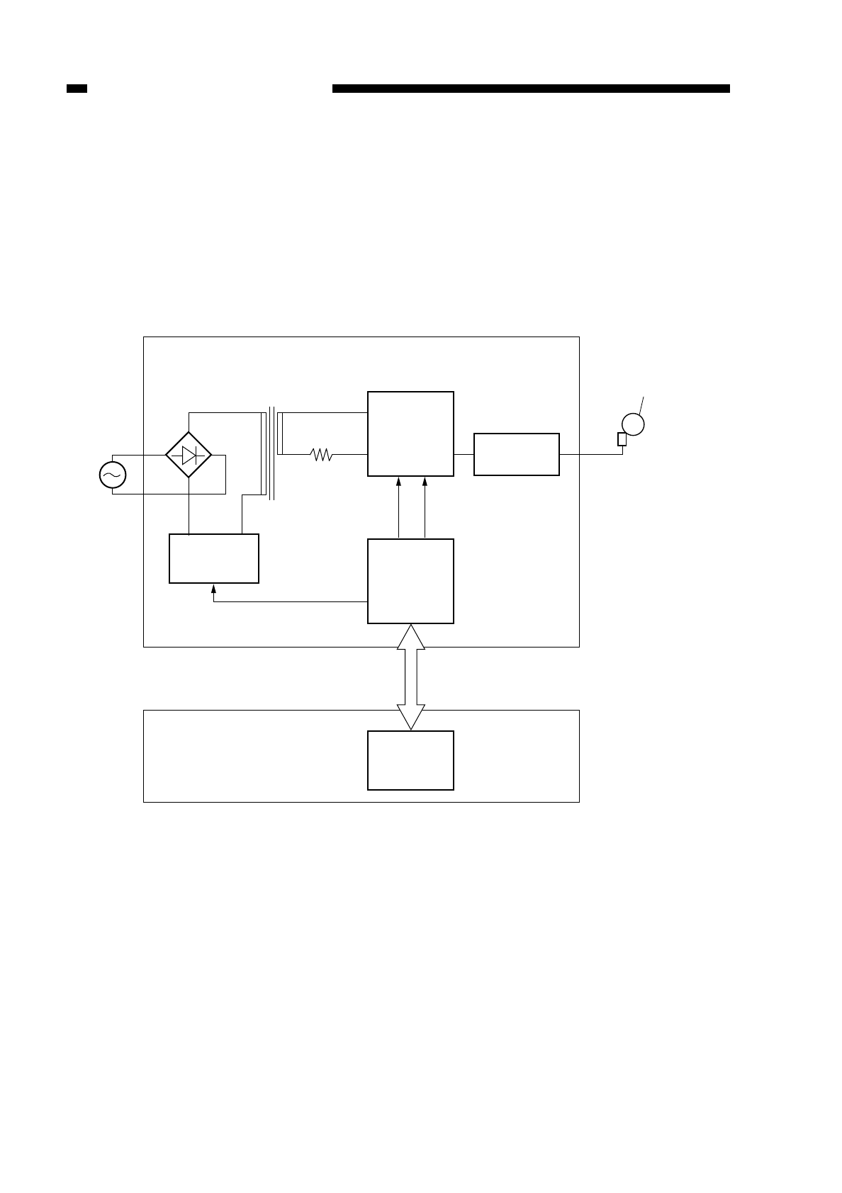
F. Controlling the Static Eliminator Bias
1. Outline
Figure 4-114 shows the circuit that controls the static eliminator bias; the circuit has
the following functions:
• turns on and off the static eliminator bias and controls the voltage to a constant
level
• switches the static eliminator bias voltage level
Figure 4-114
COPYRIGHT
©
1997 CANON INC. CANON NP6218 REV. 0 MAY 1997 PRINTED IN JAPAN (IMPRIME AU JAPON)
CHAPTER 4 IMAGE FORMATION SYSTEM
4-16
Composite power supply PCB
Main transformer
T101
JLVCTL JCTL
MPWM
Microprocessor
(Q512)
J211
11~15
J210
1~6
J302
J301
Microprocessor
(Q301)
Transformer
(T101)
drive circuit
Static eliminator
bias drive
circuit Transformer
circuit
DC controller PCB
Photosensitive drum
Static
eliminator

2. Switching the Static Eliminator Bias Voltage Level
The microprocessor (Q512) on the composite power supply PCB generates the
JCTL signal (analog signal) under the control of the DC controller PCB. In response, the
secondary side of the main transformer (T101) turns on to generate a bias for the static
eliminator with the help of the main transformer (T101).
The output of voltages (2.5 kV, 4.0 kV) is switched by the JLVCTL signal.
When the JCTL signal turns on, the drive circuit turns on to generate the static
eliminator bias.
3. Ensuring Proper Separation of Thin Paper
Under some environmental conditions, thin paper can fail to separate at times.
To ensure proper separation, the voltage applied to the static eliminator may be
permanently set to 4.0 kV.
To do this, use service mode No. 506 (separation static eliminator output voltage; see
p. 10-107).
COPYRIGHT
©
1997 CANON INC. CANON NP6218 REV. 0 MAY 1997 PRINTED IN JAPAN (IMPRIME AU JAPON)
CHAPTER 4 IMAGE FORMATION SYSTEM
4-17
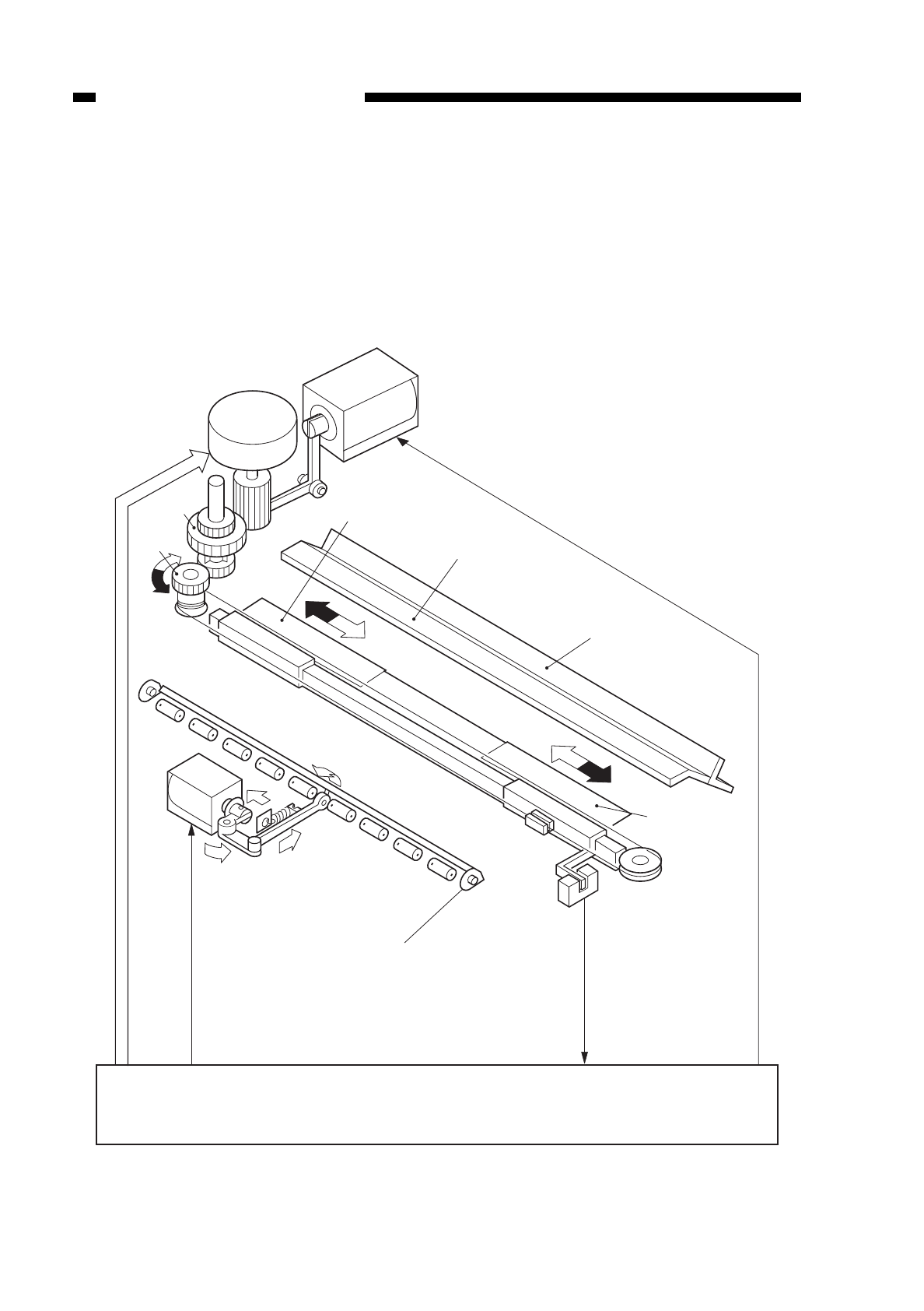
G. Controlling Blank Exposure
1. Outline
The copier uses the reflecting plate to direct the light of the pre-exposure lamp to the
photosensitive drum by way of executing blank exposure, thereby blanking (whiting) out
the non-image areas and areas between copies.
The area of blank exposure is controlled by the two slide shutters and one open/close
shutter.
Figure 4-115
COPYRIGHT
©
1997 CANON INC. CANON NP6218 REV. 0 MAY 1997 PRINTED IN JAPAN (IMPRIME AU JAPON)
CHAPTER 4 IMAGE FORMATION SYSTEM
4-18
Lens motor M
Change solenoid (SL1)
Slide shutter (rear)
Reflectiong plate
for size blanking
Gear A
Gear B
Reflectiong plate
for full blanking
Blank shutter
solenoid
(SL3)
Pre-exposure lamp
Open/close shutter
Blanking shutter home
position sensor (PS3)
Slide shutter
(front)
DC controller PCB
Blank shutter solenoid drive signal
(BSSLD*)
Blank shutter home position
detection signal (BSHP)
Change solenoid drive signal (CHSLD*)
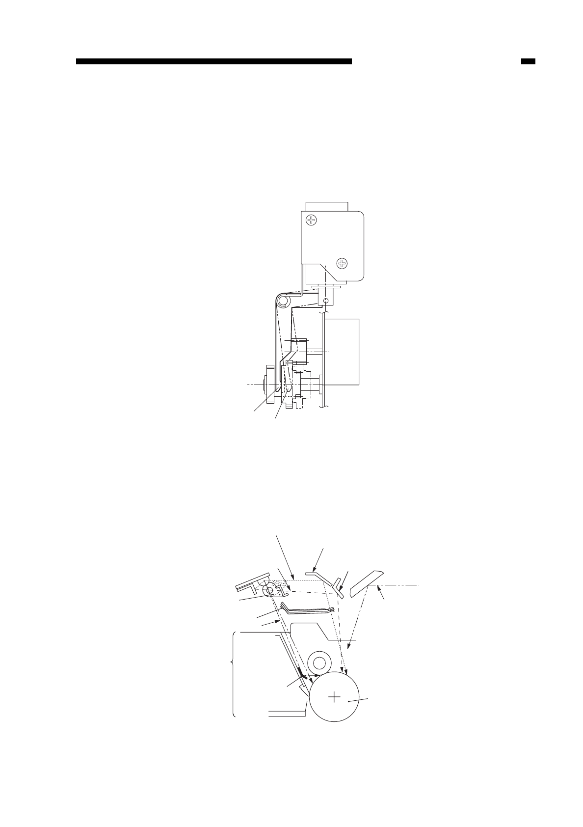
2. Blanking (Whiting) of Non-Image Areas for Reduction
In Reduce mode, the change solenoid (SL1) turns on, and the lens moves according
to the selected reproduction ratio. When the change solenoid (SL1) turns off, the drive of
the lens motor is transmitted to gears A and B, thereby moving the slide shutter (rear,
front) for the appropriate distance to open the exposure window. In this condition, the
light from the pre-exposure lamp is directed to the photosensitive drum by way of the
reflecting plate for size blanking.
Figure 4-116
3. Blanking (Whiting) Out the Leading/Trailing Edges and between Copies
The blank shutter solenoid drive signal (BSSSLD) turns on or off under the control of
the microprocessor (Q301) on the DC controller. The leading/trailing edge and the area
between copies are blacked (whited) out by opening the open/close shutter in this way.
Figure 4-117
COPYRIGHT
©
1997 CANON INC. CANON NP6218 REV. 0 MAY 1997 PRINTED IN JAPAN (IMPRIME AU JAPON)
CHAPTER 4 IMAGE FORMATION SYSTEM
4-19
AB
Size blanking optical path
Full blanking optical path
Open/close shutter
Slide shutter
Pre-exposure optical path
Drum cartridge
Drum cleaning
assembly
Pre-exposure
reflecting plate
Reflecting plate
for size blanking
Reflecting plate
for full blanking
Image exposure
optical path
Photosensitive
drum
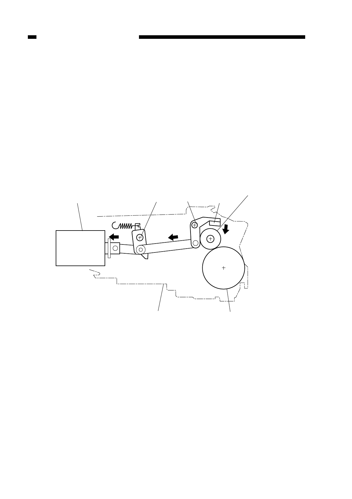
H. Controlling the Primary Corona Roller Cleaning Mechanism
1. Outline
The copier’s primary charging roller is equipped with an automatic cleaning
mechanism.
The automatic cleaning mechanism cleans the primary charging roller during initial
rotation(INTR) after having made 250 or more copies, i.e., after executing transfer roller
release control five times.
2. Primary Charging Roller Cleaning Operation
The primary charging roller cleaning solenoid (SL4) on signal (PCLSLD) is generated
under the control of the microprocessor (Q301) on the DC controller PCB. In response
to the signal, the cleaning pad is butted against the roller for 2 sec, during which time the
cleaning roller makes about 4 rotations.
Figure 4-118
COPYRIGHT
©
1997 CANON INC. CANON NP6218 REV. 0 MAY 1997 PRINTED IN JAPAN (IMPRIME AU JAPON)
CHAPTER 4 IMAGE FORMATION SYSTEM
4-20
Primary charging roller
cleaning solenoid Fulcrum Fulcrum Cleaning pad
Primary
charging
roller
Drum unit Drum
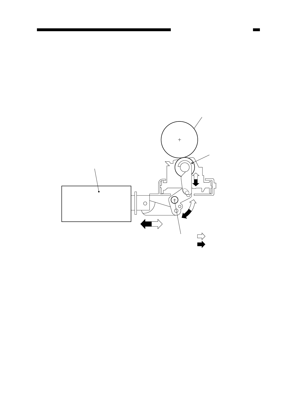
I. Releasing the Transfer Roller
1. Outline
The copier’s transfer roller is equipped with a releasing mechanism.
The releasing mechanism releases the transfer roller to prevent adhesion of toner to
the roller under the following condition:
• during post rotation (LSTR) after as many as 50 copies or more have been made
(cumulative)
Figure 4-119
COPYRIGHT
©
1997 CANON INC. CANON NP6218 REV. 0 MAY 1997 PRINTED IN JAPAN (IMPRIME AU JAPON)
CHAPTER 4 IMAGE FORMATION SYSTEM
4-21
Transfer roller
releasing solenoid
Photosensitive drum
Transfer roller
Fulcrum engaging
releasing
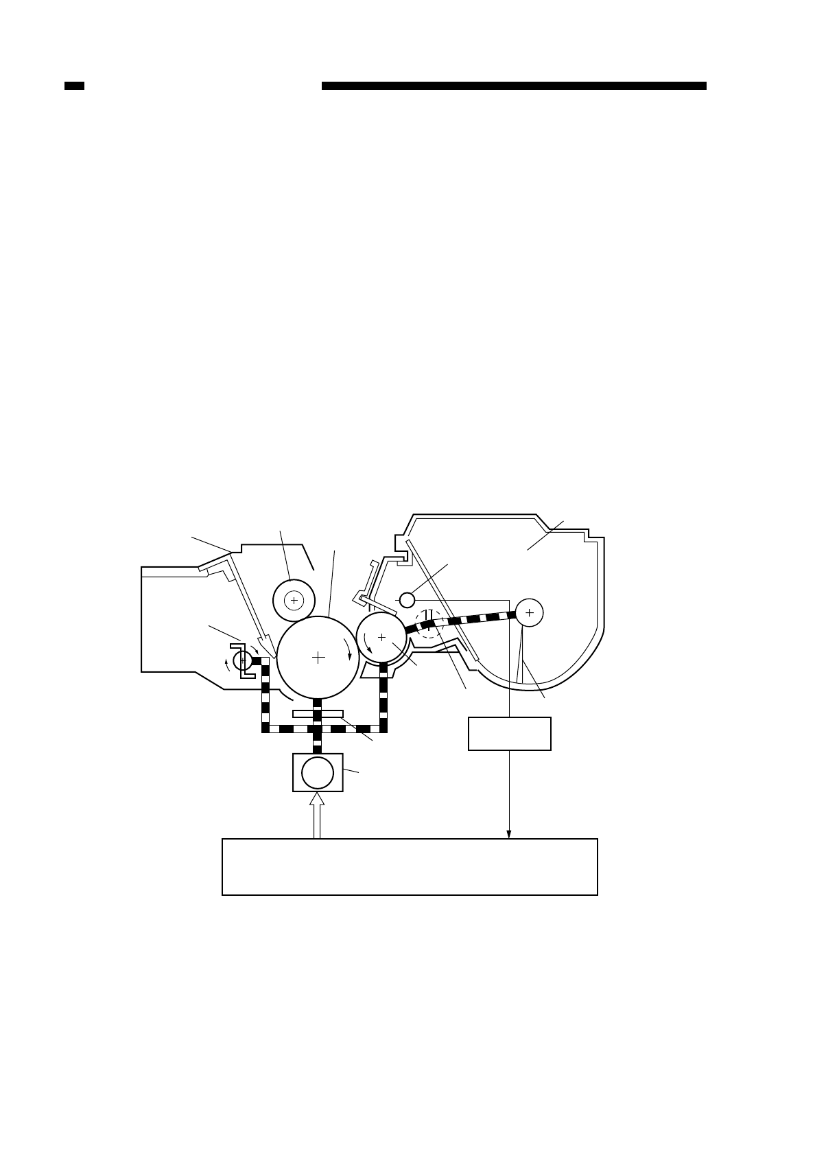
II. DEVELOPING ASSEMBLY AND CLEANING
ASSEMBLY
A. Outline
The copier’s photosensitive drum, developing cylinder, No. 1 stirring rod, and No. 2
stirring blade are rotated by the drive of the main motor (M1).
The level of the toner inside the developing assembly is monitored by the toner
sensor; when it drops below a specific level, the Add Toner indicator flashes on the
display of the control panel.
The No. 1 stirring rod serves to supply toner to the developing cylinder and stir the
toner flow layer inside the developing chamber.
The No. 2 stirring blade is used to stir the toner inside the toner container and, at the
same time, to supply toner to the developing chamber.
The waste toner collected by the cleaning blade is forwarded by the waste toner feed
blade for collection inside the waste toner assembly.
Figure 4-201
COPYRIGHT
©
1997 CANON INC. CANON NP6218 REV. 0 MAY 1997 PRINTED IN JAPAN (IMPRIME AU JAPON)
CHAPTER 4 IMAGE FORMATION SYSTEM
4-22
M1
Cleaning blade
Waste toner
feeding blade
Waste toner
assembly
Primary charging
roller
Drum cartridge
Photosensitive
drum
Toner sensor
Toner container
Developing
cylinder No. 1
stirring rod No. 2 stirring blade
Toner level
detection PCB
Torque limiter
Main motor/
Main motor
driver PCB
Motor drive signal
DC controller PCB
Toner out signal
(TEP*)
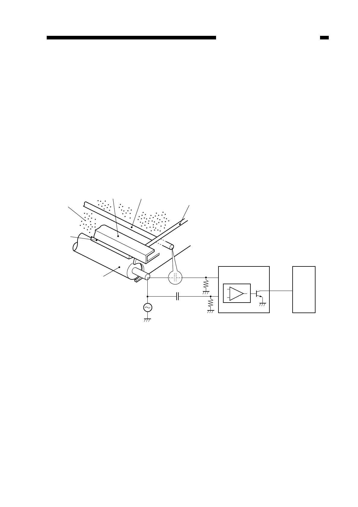
B. Controlling the Toner Level Detection
The level of toner inside the cartridge is monitored by the antenna sensor circuit.
The toner level sensor is found inside the cartridge, and an AC bias is applied to the
developing cylinder.
The developing cylinder and the toner level sensor are connected by means of static
electricity; the volumes of charges between the two vary according to the amount of
toner inside the cartridge; as a result, an AC bias that represents the level of the toner
is checked by the toner level sensor, and the data is sent to the antenna sensor circuit.
The antenna sensor circuit receives a reference signal from the composite power
supply circuit; the reference signal is an AC bias with a specific AC bias that has gone
through attenuation.
In the antenna circuit, the signal coming from the toner level sensor and the
reference signal are compared to find out the level of toner.
Figure 4-202
COPYRIGHT
©
1997 CANON INC. CANON NP6218 REV. 0 MAY 1997 PRINTED IN JAPAN (IMPRIME AU JAPON)
CHAPTER 4 IMAGE FORMATION SYSTEM
4-23
Toner
Blade
Developing cylinder
Blade mount Toner level
sensor Developing assembly
frame
Antenna sensor circuit
Comparator circuit
DC controller
PCB
TEP*
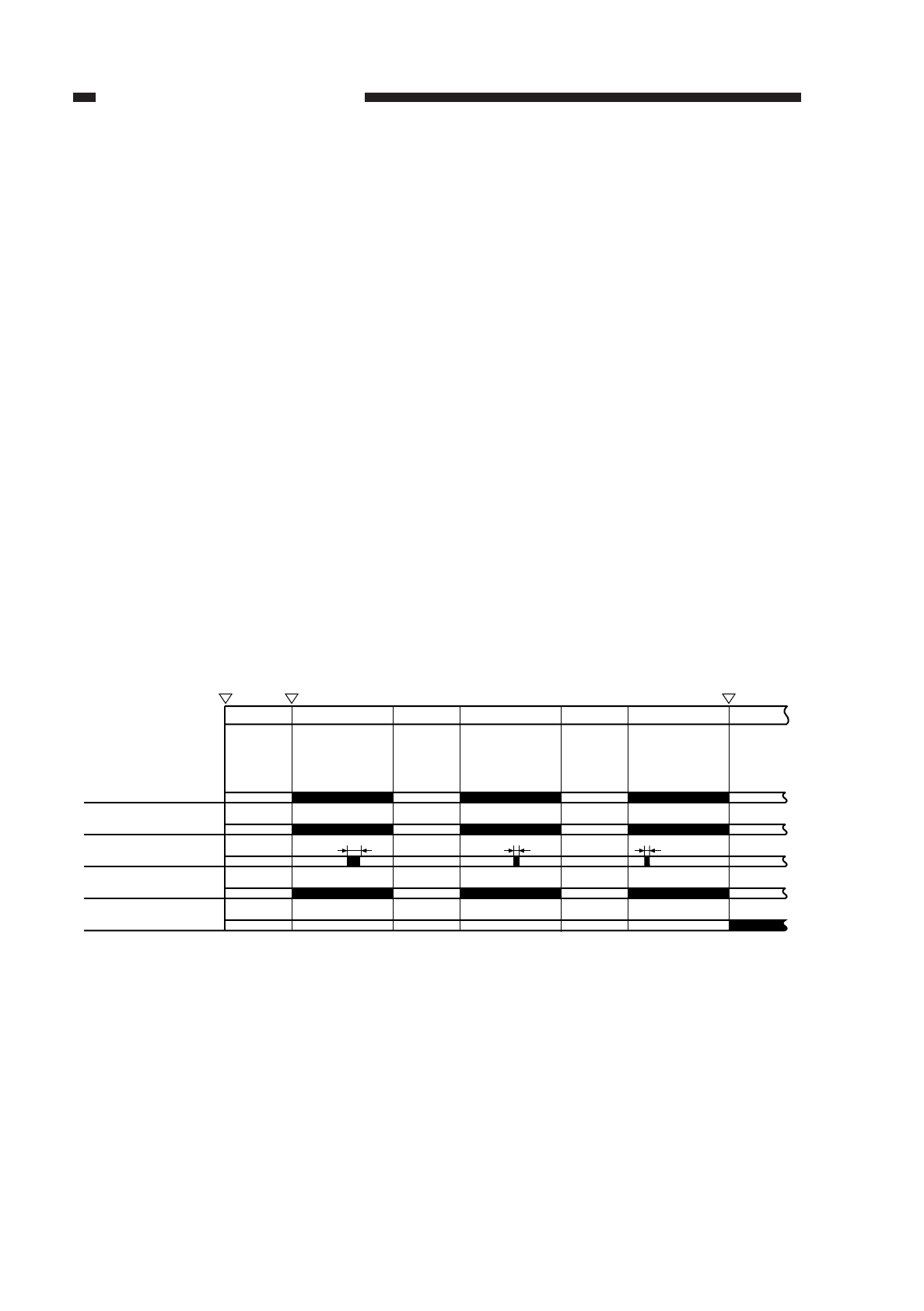
qWhen the Level of Toner Is Adequate
The presence of toner around the toner level sensor causes the AC bias generated
by the sensor to be larger than the reference signal.
The condition causes the output from the comparator circuit to go ‘1’ and the toner
out signal (TEP*) to go ‘0’.
wWhen the Level of toner Is Inadequate
The toner around the toner level sensor decreases in amount, causing the AC bias
generated by the sensor to lower.
Since the reference signal, on the other hand, remains unchanged, the output
voltage remains high.
The difference in the potential causes the output of the comparator circuit to go ‘0’,
causing the toner out signal (TEP*) to go ‘1’.
The condition causes the microprocessor (Q301) in the DC controller cirucit to make
checks only during copying operating (AC bias ON); if it detects the toner out signal=0,
each lasting 0.25 sec or more, for a total time equivalent of three copies, the Cartridge
indicator is flashed on the display of the control panel.
eTorque Limiter
If an excessive load is imposed on the photosensitive drum because of excessive
amounts of waste toner or some other reason while the drum is rotating, the torque
limiter cuts off the drive from the main motor to stop the rotating of the drum.
Figure 4-203
COPYRIGHT
©
1997 CANON INC. CANON NP6218 REV. 0 MAY 1997 PRINTED IN JAPAN (IMPRIME AU JAPON)
CHAPTER 4 IMAGE FORMATION SYSTEM
4-24
STBY
Copy Start key
ON
Main motor (M1)
Toner level detection timing
Toner out signal (TEP*)
AC bias
Power switch
ON Cartridge indicator
flashing timing
A4, AE3 copies, continuous mode
Cartridge indicator (tlashing)
1st (3 sec) 2nd (1 sec) 3rd (0.5 sec)
Copy STBY Copy STBY Copy
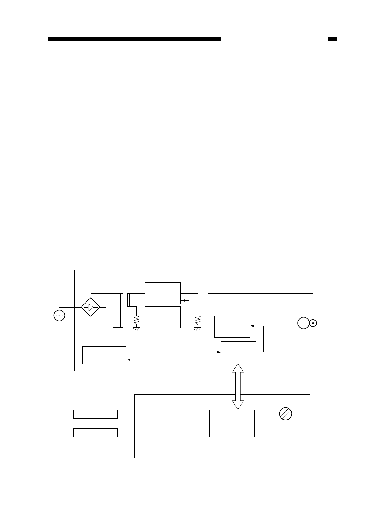
C. Controlling the Development Bias
1. Outline
Figure 4-204 shows the circuit used to control the development bias; the circuit has
the following functions:
• turns on and off the AC component of the development bias
• turns on and off the DC component of the development bias
• controls the voltage level of the DC component of the development bias
• controls the DC component of the development bias to a constant level
2. Turning On and Off the DC Component of the Developing Bias and Controlling
the Voltage to a Constant Level
The microprocessor (Q512) on the composite power supply PCB generates the
BPWM signal (pulse signal) under the control of the microprocessor master (Q301) on
the DC controller PCB. In response, the secondary side of the main transformer (T101)
turns on to apply the DC component of the development bias.
In addition, while the DC component of the development bias is being applied, the
application voltage is taken in from the development DC bias voltage detection circuit in
the form of the BIASS signal (analog signal) to exert control so that the output voltage is
maintained at a constant level.
The main transformer (T101) is driven by the drive signal (MPWM) from the
microprocessor (Q512). In addition to the foregoing functions, the main transformer
(T101) is also used as the high-voltage transformer for the DC power supply and other
loads.
Figure 4-204
COPYRIGHT
©
1997 CANON INC. CANON NP6218 REV. 0 MAY 1997 PRINTED IN JAPAN (IMPRIME AU JAPON)
CHAPTER 4 IMAGE FORMATION SYSTEM
4-25
Composite power supply PCB
Main transformer
T101
Transformer (T101)
drive circuit
Development
DC bias drive
circuit
Development
DC bias voltage
detection circuit
Development AC bias
transformer
T301
BPWM
BIASS
MPWM
J211
1~15
J210
1~6
J302
J301
Development
AC transformer
drive circuit
Microprocessor
(Q512)
Photosensitive
drum
Developing cylinder
AE sensor
Copy Density key
DC controller PCB
Microprocessor
(Q301) Copy density
correction volume
(VR302)
ACBIAS
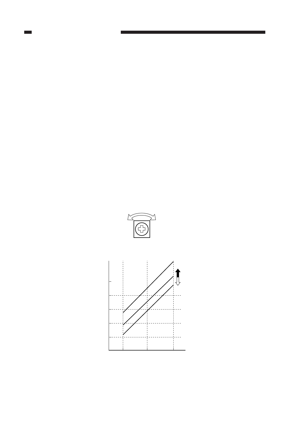
3. Turning On and Off the AC Component of the Development Bias
The microprocessor (Q512) on the composite power supply PCB generates the
ACBIAS signal (pulse signal) under the control of the microprocessor master (Q301) on
the DC controller PCB. In response to the signal, the development bias AC component
generating transformer (T301) turns on to add the AC component of the development
bias to the DC component for application.
• application frequency 2400 Hz (approx.)
• application voltage 1300 Vp-p (approx.)
4. Controlling the Voltage Level of the DC Component of the Development Bias
The copier modifies the voltage level of the DC component of the development bias
based on the following factors:
• setting of the Copy Density key
• output of the AE sensor
• position of the Copy Density Correction knob (VR302)
The copier controls so that the voltage of the DC component of the development bias
varies between –80 and –560 V (in actual terms) by varying the output of the BPWM
signal.
To ompensate increases in the
light
potential (VL) caused by deterioration of the
photosensitive drum, the copier is equipped with a copy density correction volume. You
may operate the volume (VR302) on the DC controller PCB to adjust the potential of the
DC bias for any increase in VL, thereby freeing the copies of fogging.
Figure 4-205
COPYRIGHT
©
1997 CANON INC. CANON NP6218 REV. 0 MAY 1997 PRINTED IN JAPAN (IMPRIME AU JAPON)
CHAPTER 4 IMAGE FORMATION SYSTEM
4-26
(to lighter) (to darker)
VR302
Developing bias
(DC component)
-500
-400
-100
Darker
Medium
Lighter
(darker) 5
Copy density
(lighter)
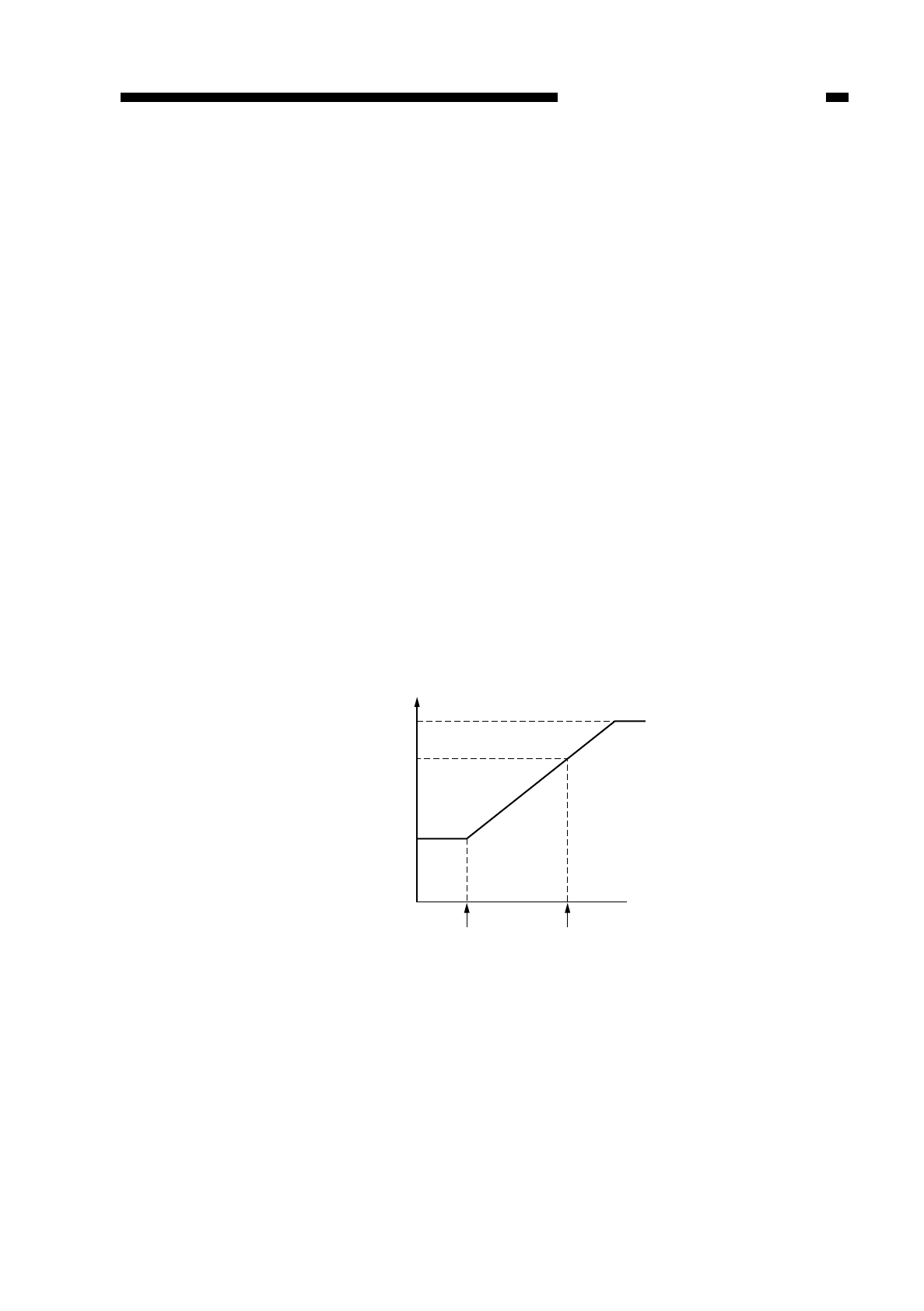
D. Automatic Control of Copy Density
1. Outline
The copier has an automatic density adjustment mechanism (AE), which
automatically controls the DC component of the development bias according to the
density of originals. As long as the original is more or less uniform in density, the AE
mechanism varies the DC component of the development bias accordingly to ensure
fogging-free copies.
The DC component controlled in AE mode is indicated in the copy density display of
the control panel.
2. Control Method
During initial rotation (INTR), the scanning lamp (FL1) is turned on at a specific
intensity and the scanner is moved forward about 65 mm to expose the original.
With the scanner in this position, the reflected light over the area shown in Figure 4-
207 is measured by the AE sensor (photodiode), and the measurements are sent to the
DC controller PCB.
In response, the DC controller PCB computes the optimum value of the development
DC bias for copying operation, and generates the result to the microprocessor on the
composite power supply. Figure 4-206 shows the changes in the DC component of the
development bias caused by the changes in the density of an original.
The graph is based on the amount of exposure that brings optimum density without
fogging when copies are made of a newspaper or a Test Sheet.
Figure 4-206
COPYRIGHT
©
1997 CANON INC. CANON NP6218 REV. 0 MAY 1997 PRINTED IN JAPAN (IMPRIME AU JAPON)
CHAPTER 4 IMAGE FORMATION SYSTEM
4-27
Developing DC bias
Copy density 9
(equivalent)
Copy density 7.5
(equivalent)
Copy density 5
(equivalent)
Test Sheet Density of original
Newspaper
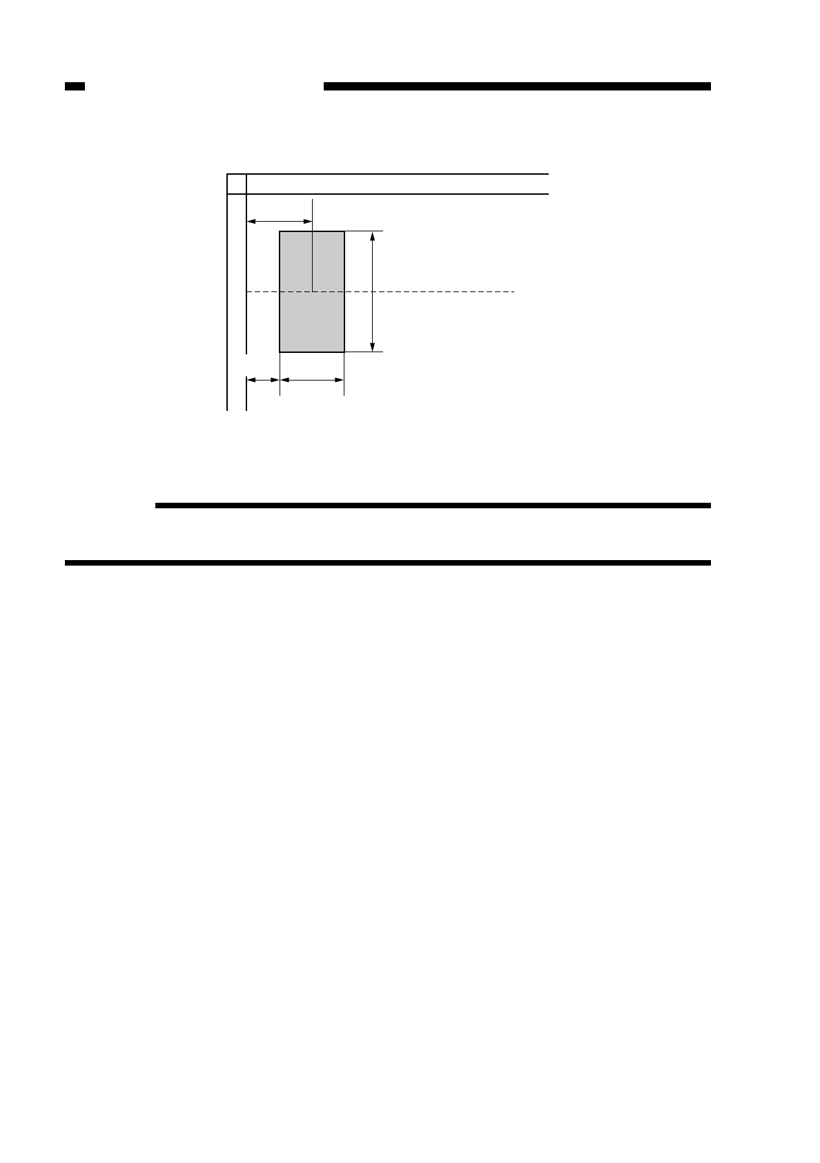
Figure 4-207 (Area Read by the AE Sensor)
Reference:
When copies are made in AE using an ADF-E1 (accessory), the density is checked
for each original.
COPYRIGHT
©
1997 CANON INC. CANON NP6218 REV. 0 MAY 1997 PRINTED IN JAPAN (IMPRIME AU JAPON)
CHAPTER 4 IMAGE FORMATION SYSTEM
4-28
27 mm
(approx.)
Center reference
50 mm (approx.)
A
14 mm
(approx.) 27 mm
(approx.)
Note: A indiates the position of the AE sensor
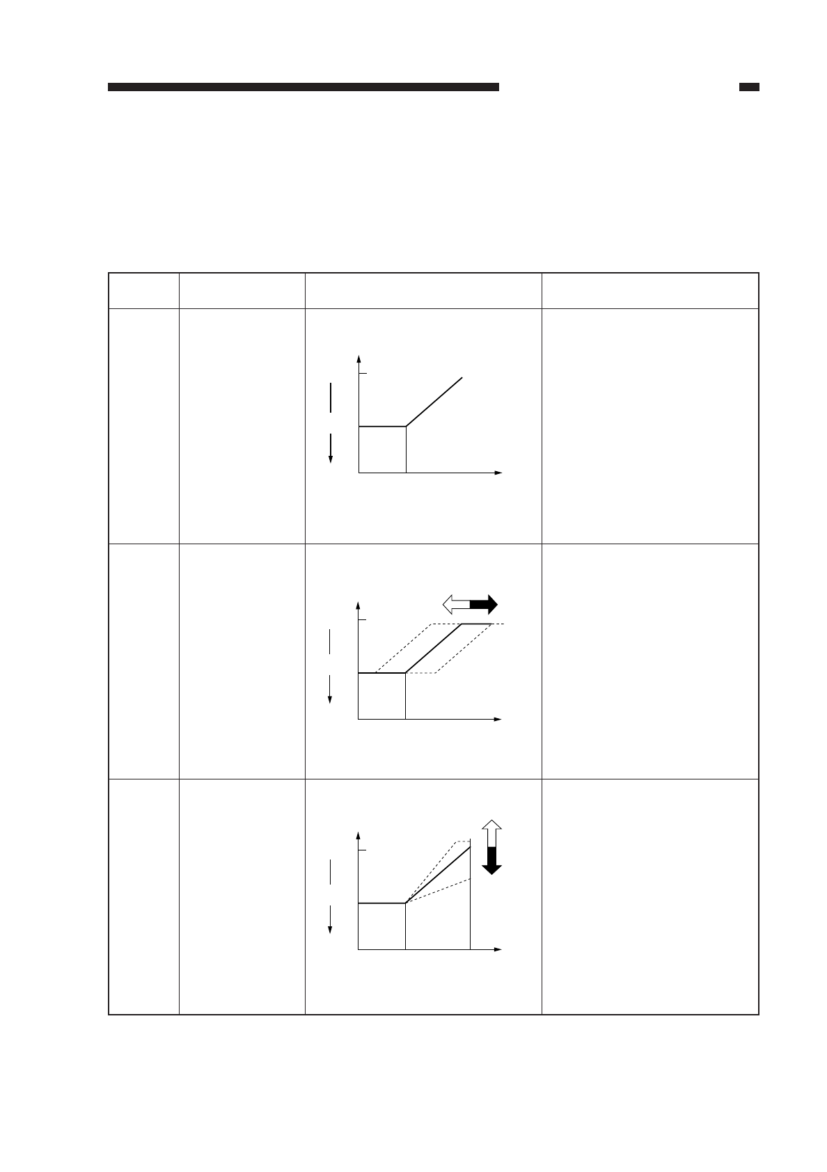
3. AE Adjustment
The copier’s AE adjustment is executed in service mode and consists of the following
three types:
• lamp intensity automatic adjustment (No. 301) during AE scans
• copy density (development bias) standard adjustment (No. 302) during AE mode
• copy density (development bias) slope adjustment (No. 303) during AE mode
Table 4-201
Item
No. 301
No. 302
No. 303
COPYRIGHT
©
1997 CANON INC. CANON NP6218 REV. 0 MAY 1997 PRINTED IN JAPAN (IMPRIME AU JAPON)
CHAPTER 4 IMAGE FORMATION SYSTEM
4-29
Description
Lamp intensity
automatic
adjustment dur-
ing AE scans
Copy density
(development
bias) standard
adjustment
during AE
mode
Copy density
(development
bias) slope
adjustment
during AE
mode
Adjustments Remarks
The density is adjusted auto-
matically so that the copy
density will be 5 when mak-
ing copies of the Test Chart.
qIf the setting is decreased
in service mode,
→AE copies will be
darker.
wIf the setting is increased
in service mode,
→AE copies will be
lighter.
default: 0
settings: -26 to +26
qIf the setting is increased
in service mode,
→copies of a newspaper
will be lighter.
wIf the setting is decreased
in service mode,
→copies of a newspaper
will be darker.
default: 0
settings: -26 to +26
Lighter
Copy
density
Density
Test Chart
9
5
Density of
Original
Lighert
Copy
density
Density
Test Chart
9
5
Density of
Original
qw
Lighter
Copy
density
Density
Test Chart
9
5
Density of
Original
q
w
Newspaper
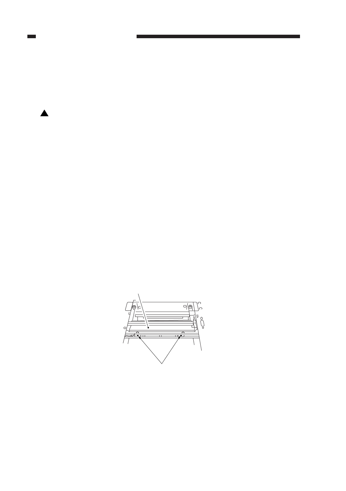
III. DISASSEMBLY AND ASSEMBLY
This section explains mechanical characteristics and describes how to
disassemble/assemble the machine.
Be sure to observe the following when disassembling/assembling the machine:
1. Disconnect the power plug before starting the work.
2. Unless otherwise shown, assemble the parts by reversing the steps given to
disassemble them.
3. Identify each screw by type (length, diameter) and location.
4. A washer is used for one of the mounting screws on the rear cover to protect against
static electricity; be sure to use the washer when assembling the part.
5. A washer is used for some mounting screws (for grounding wire, varistor) to ensure
correct electrical continuity; be sure to use the washer when assembling the part.
6. As a rule, do not operate the machine while any of its parts are removed.
7. When sliding out the duplexing unit or the fixing assembly, be sure to turn off the front
door switch or the power switch.
A. Illumination Assembly
1. Detaching the Scanning Lamp/Fluorescent Lamp Heater
1) Disconnect the power plug.
2) Detach the copyboard glass.
3) Detach the upper rear cover.
4) Move the scanner unit near the center.
5) Remove the two screws q, and detach the light-blocking plate w.
Figure 4-301
!
COPYRIGHT
©
1997 CANON INC. CANON NP6218 REV. 0 MAY 1997 PRINTED IN JAPAN (IMPRIME AU JAPON)
CHAPTER 4 IMAGE FORMATION SYSTEM
4-30
w
q
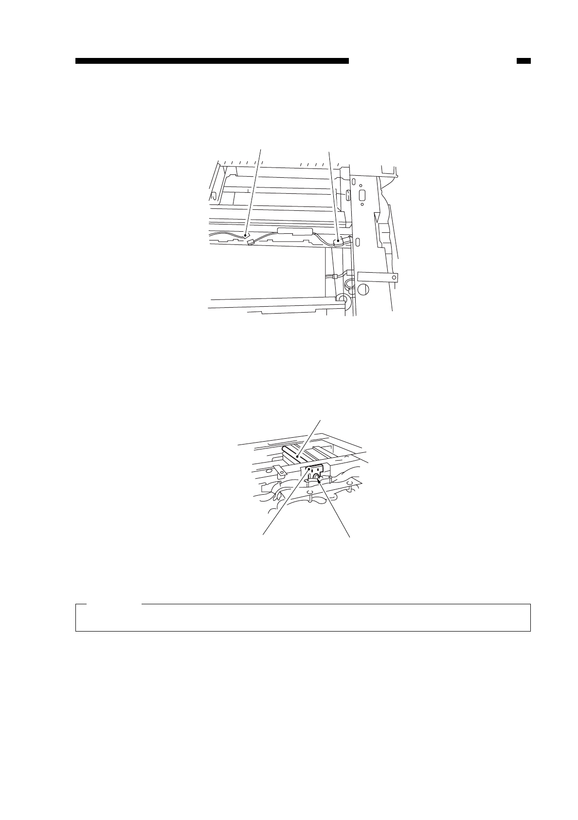
6) Disconnect the connectors e, r.
Figure 4-302
7) Remove the screw t, and disconnect the connector y.
8) Pull the fluorescent lamp uslowly toward the front to detach.
Figure 4-303
Caution:
Do not touch the fluorescent lamp. (Use lint-free paper.)
COPYRIGHT
©
1997 CANON INC. CANON NP6218 REV. 0 MAY 1997 PRINTED IN JAPAN (IMPRIME AU JAPON)
CHAPTER 4 IMAGE FORMATION SYSTEM
4-31
r
e
u
t
y
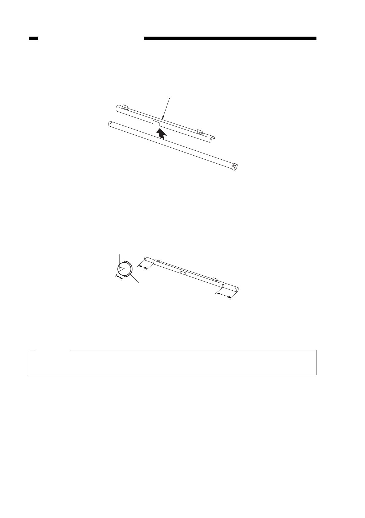
9) Detach the fluorescent lamp heater ifrom the fluorescent lamp.
Figure 4-304
2. Points to Note When Attaching the Fluorescent Lamp Heater/Scanning Lamp
• Attach the heater to the lamp as follows:
Figure 4-305
Caution:
Do not touch the fluorescent lamp. (Use lint-free paper.)
Do not block the light-emitting portion by the fluorescent lamp heater.
COPYRIGHT
©
1997 CANON INC. CANON NP6218 REV. 0 MAY 1997 PRINTED IN JAPAN (IMPRIME AU JAPON)
CHAPTER 4 IMAGE FORMATION SYSTEM
4-32
i
Light-emitting
portion
Heater
1~5mm
60mm 60mm
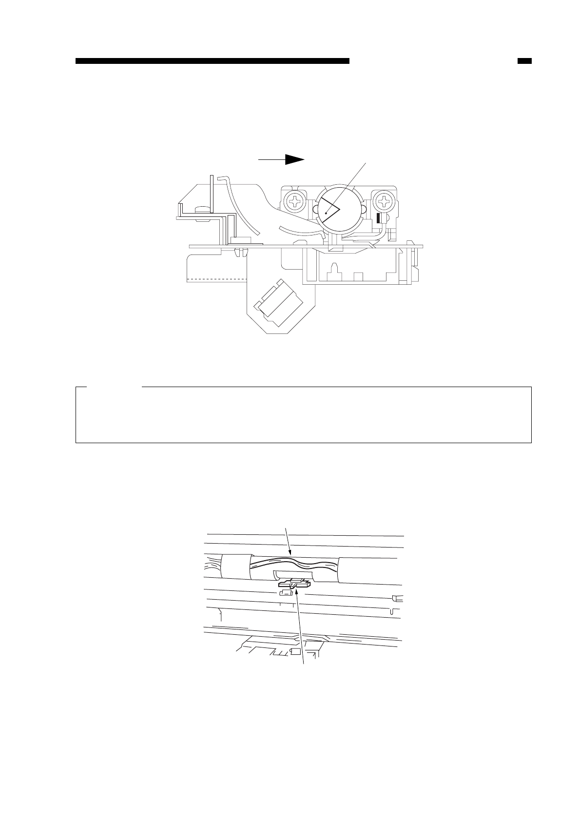
Attach the scanning lamp so that its light-emitting portion (open side) is to the left
when viewed from the front of the copier as shown in Figure 4-306.
Figure 4-306 (front view)
Caution:
Do not touch the fluorescent lamp. (Use rint-free paper)
Be sure to adjust the gain and AE whenever you have replaced the fluorescent
lamp. (See p. 10-10.)
• Make sure that the cut-off of the fluorescent heater is correctly oriented in relation
to the intensity adjustment sensor.
Figure 4-307
COPYRIGHT
©
1997 CANON INC. CANON NP6218 REV. 0 MAY 1997 PRINTED IN JAPAN (IMPRIME AU JAPON)
CHAPTER 4 IMAGE FORMATION SYSTEM
4-33
Light-emitting
portion
Adjustment sensor
Fluorescent heater
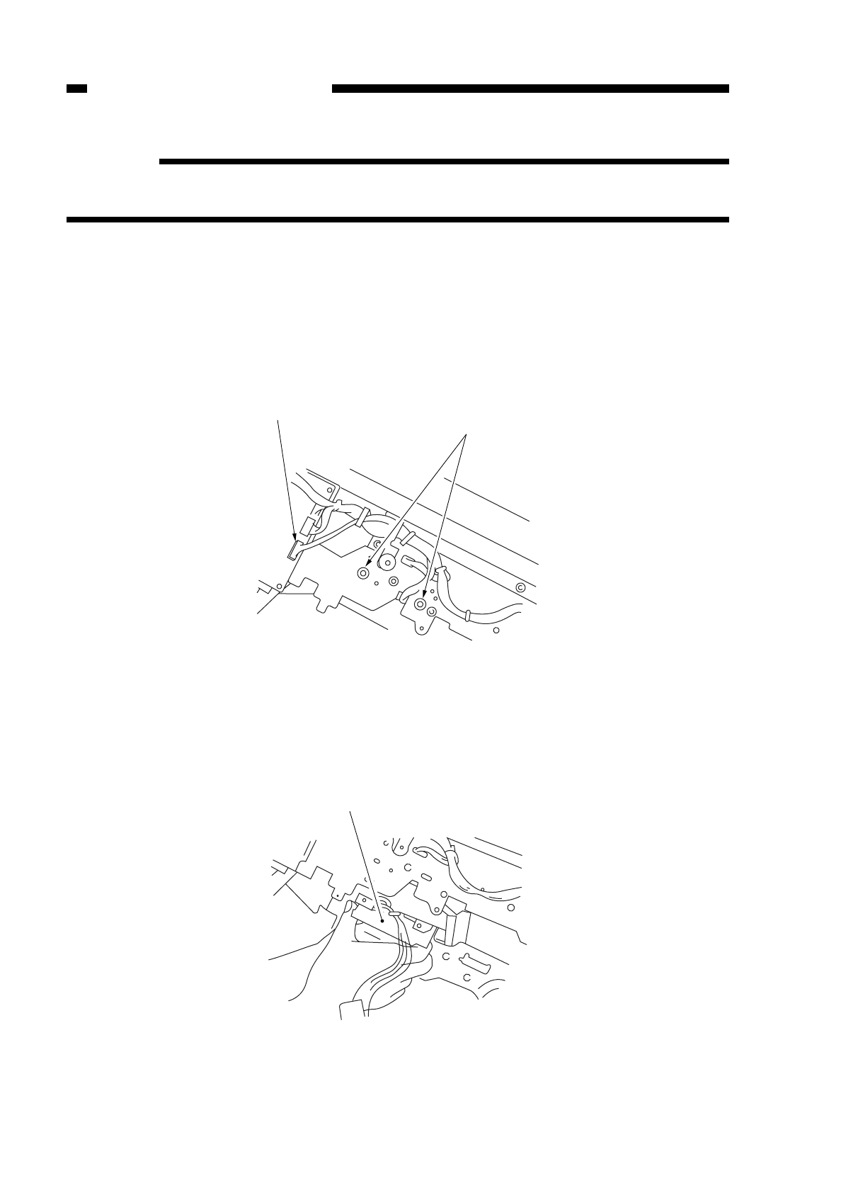
Reference:
The fluorescent lamp heater will not operate unless the copier’s heater switch is
turned on.
3. Detaching the Blank Exposure Assembly
1) Open the front cover.
2) Pull the copier’s open/close lever to open the copier.
3) Detach the inside cover.
4) Detach the exhaust fan and Drum cartridge. (See “Detaching the Exhaust Fan”.)
5) Disconnect the connector q(J315) on the DC controller PCB, and remove the two
screws w.
Figure 4-308
6) Push up the blank exposure assembly elightly upward, and pull it out toward the
bottom front.
Figure 4-309
COPYRIGHT
©
1997 CANON INC. CANON NP6218 REV. 0 MAY 1997 PRINTED IN JAPAN (IMPRIME AU JAPON)
CHAPTER 4 IMAGE FORMATION SYSTEM
4-34
qw
e
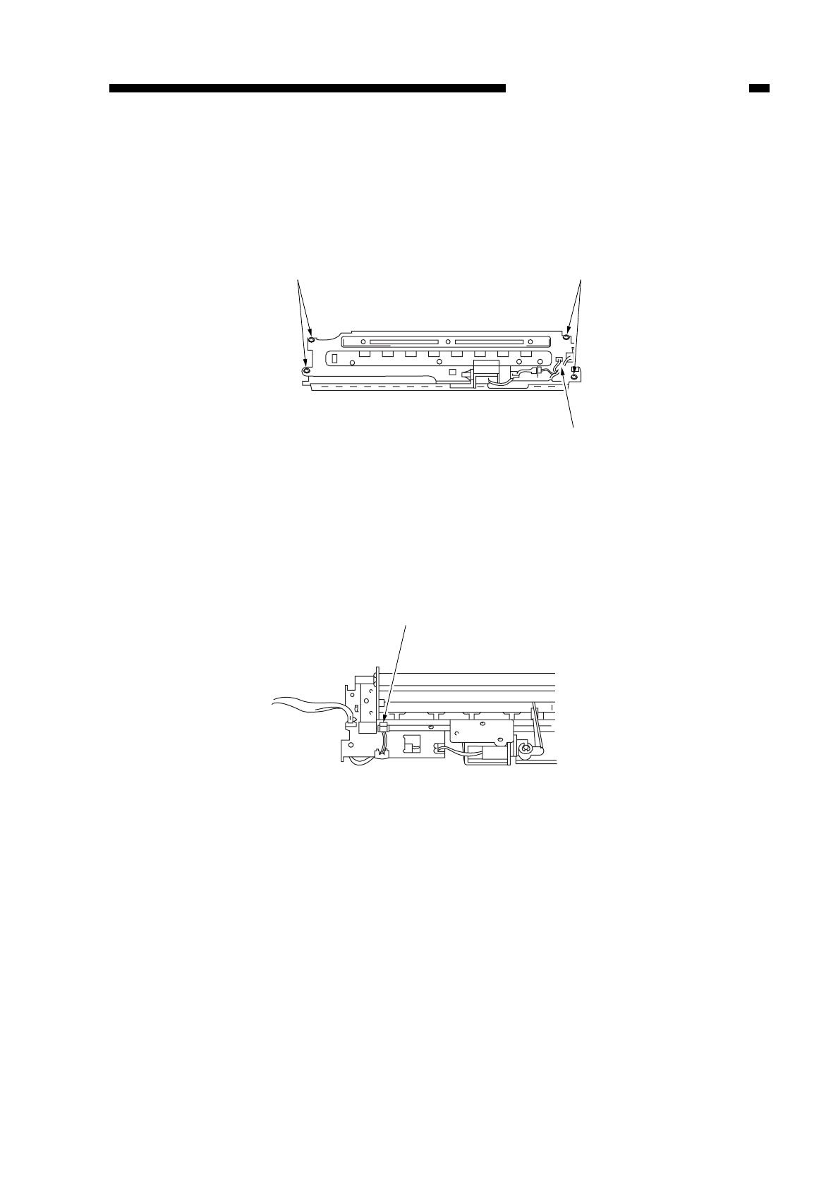
4. Detaching the Blank Exposure Lamp
1) Detach the blank exposure assembly. (See “3. Detaching the Blank Exposure
Assembly on p. 4-34.”)
2) Remove the four screws q, and disconnect the connector w.
Figure 4-310
3) Disconnect the connector e.
Figure 4-311
COPYRIGHT
©
1997 CANON INC. CANON NP6218 REV. 0 MAY 1997 PRINTED IN JAPAN (IMPRIME AU JAPON)
CHAPTER 4 IMAGE FORMATION SYSTEM
4-35
qq
w
e
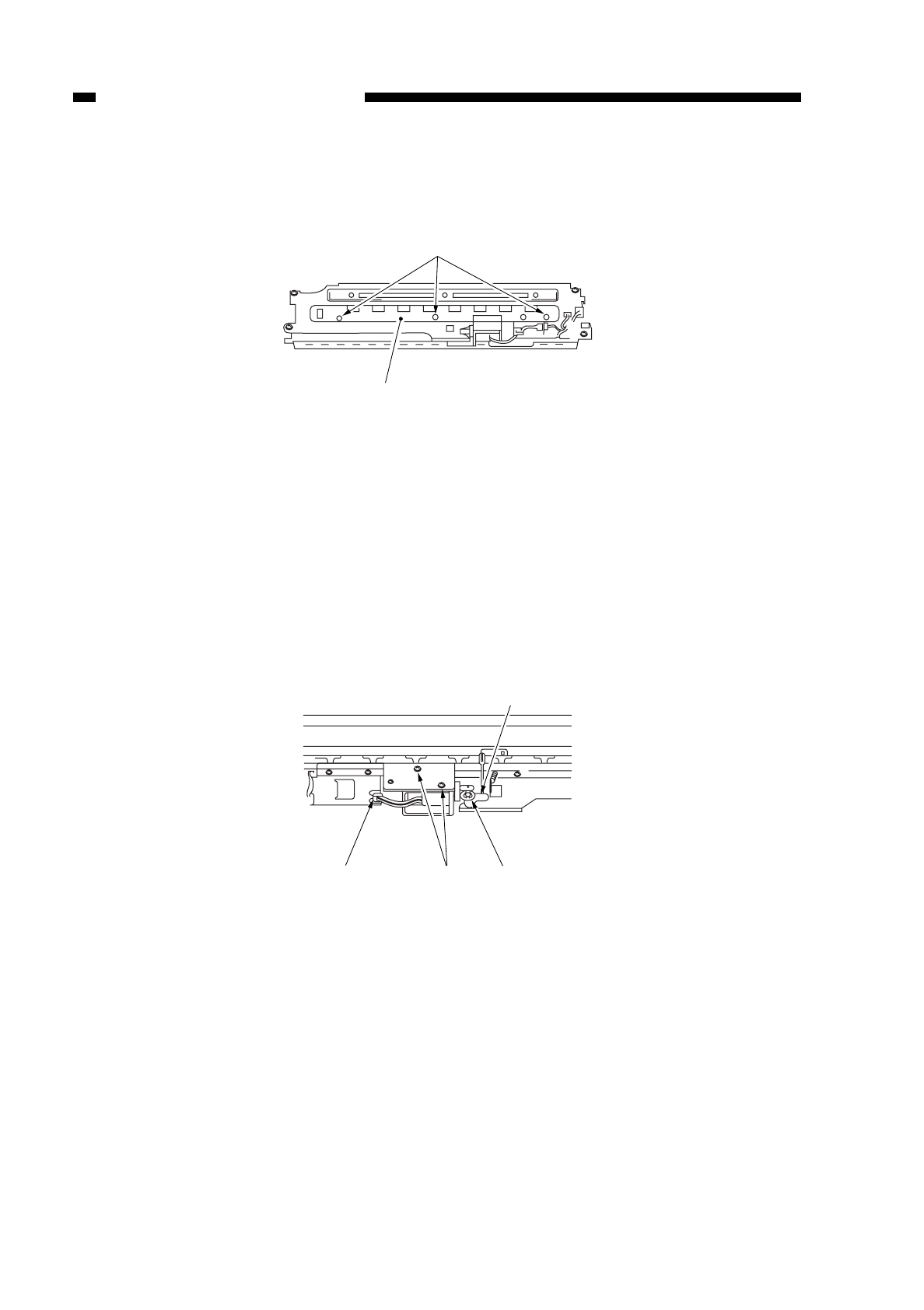
4) Remove the three screws r, and detach the blank exposure lamp t.
Figure 4-312
5. Detaching the Blank Shutter Solenoid
1) Detach the blank exposure assembly.
2) Detach the blank shutter upper plate, and disconnect the connector q. (See “3.
Detaching the Blank Exposure Assembly on p. 4-34.”)
3) Remove the E-ring w, and detach the link arm efrom the blank shutter.
4) Remove the two screws r, and pull out the blank shutter solenoid.
Figure 4-313
COPYRIGHT
©
1997 CANON INC. CANON NP6218 REV. 0 MAY 1997 PRINTED IN JAPAN (IMPRIME AU JAPON)
CHAPTER 4 IMAGE FORMATION SYSTEM
4-36
r
t
e
r
qw
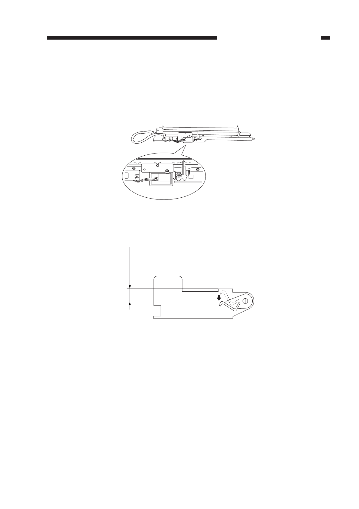
6. Positioning the Blank Shutter Solenoid
Adjust the position of the solenoid so that the bottom A is 7.7 ±0.5 mm on both sides
of the shutter when the solenoid is moved in the direction of activation. When taking
measurements, do not push down the shutter.
After adjustments, make sure that the solenoid moves smoothly.
Figure 4-314
a
Figure 4-314b
COPYRIGHT
©
1997 CANON INC. CANON NP6218 REV. 0 MAY 1997 PRINTED IN JAPAN (IMPRIME AU JAPON)
CHAPTER 4 IMAGE FORMATION SYSTEM
4-37
A
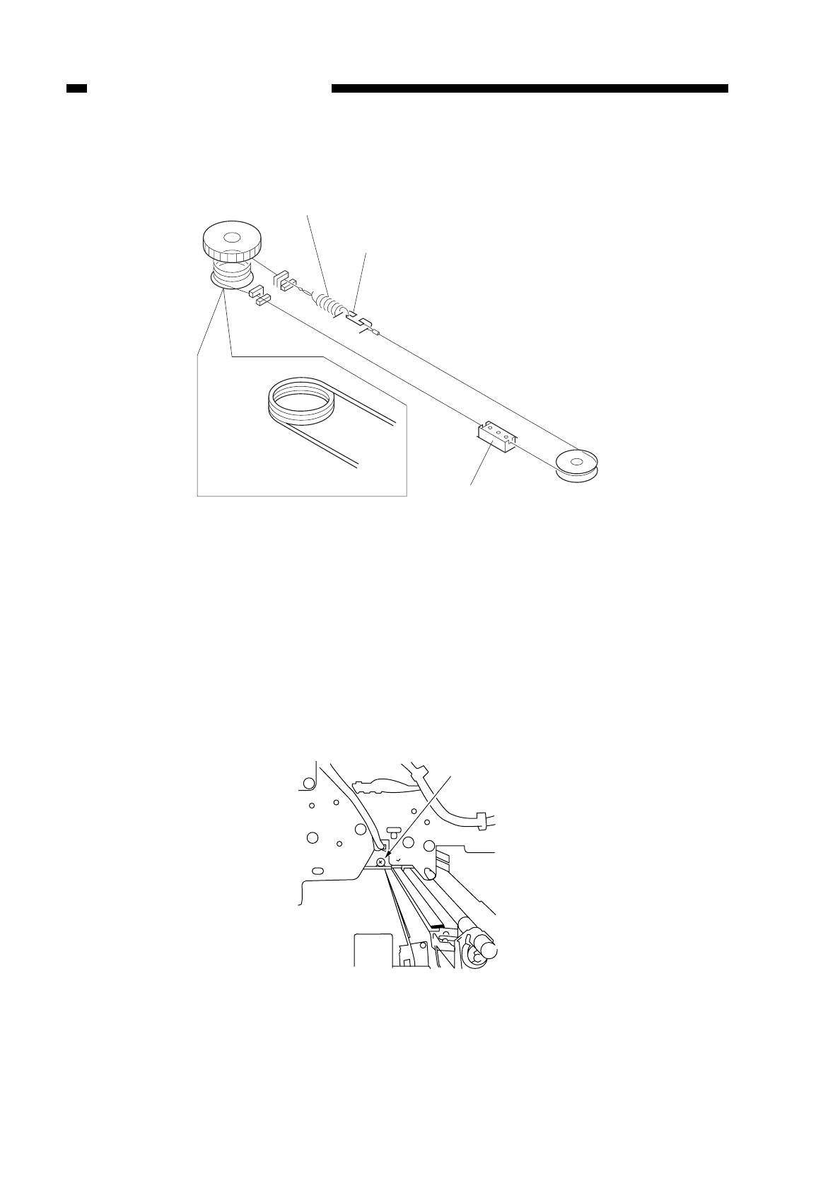
7. Routing the Blanking Cable
Figure 4-315
8. Positioning the Left/Right Margin
Turn the blanking shutter adjusting screw on the copier’s front side plate shown in
Figure 4-316 so that the standards are met.
qclockwise turn moves the margin to the front.
wcounterclockwise turn moves the margin to the rear.
ea full turn moves about 1 mm.
Figure 4-316
COPYRIGHT
©
1997 CANON INC. CANON NP6218 REV. 0 MAY 1997 PRINTED IN JAPAN (IMPRIME AU JAPON)
CHAPTER 4 IMAGE FORMATION SYSTEM
4-38
Put the spring on the outside.
Slide shutter (rear)
Wind 3.5 items
Slide shutter (front)
q
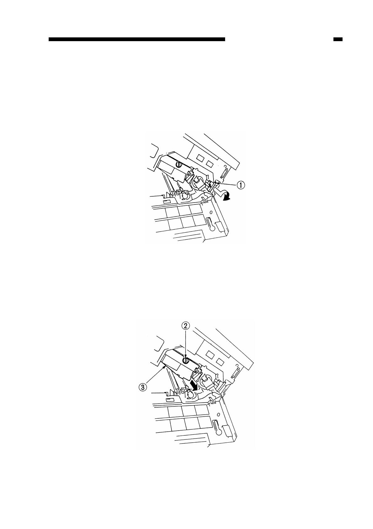
B. Drum Unit
1. Detaching the Drum Unit
1) Open the front door.
2) Pull out the developing assembly releasing lever qtoward the front, and turn it
clockwise.
Figure 4-317
3) Open the copier’s top unit.
4) Turn the knob wcounterclockwise to detach.
5) Pull out the drum unit etoward the front.
Figure 4-318
COPYRIGHT
©
1997 CANON INC. CANON NP6218 REV. 0 MAY 1997 PRINTED IN JAPAN (IMPRIME AU JAPON)
CHAPTER 4 IMAGE FORMATION SYSTEM
4-39

Caution:
Take care not to damage the photosensitive drum.
The photosensitive drum is highly susceptible to light, and exposure even to room
lighting can lead to white spots or black bands on the copies.
As a rule, do not turn on the copier with the drum unit removed; otherwise, the
registration roller and the transfer guide will interfere with each other, and rotation
of the registration roller during WMUP will damage the roller.
2. Cleaning
If the surface of the photosensitive drum has become soiled, clean it with a flannel
cloth coated with toner; do not use paper, lint-free or otherwise.
Caution:
Do not dry-wipe or use solvent.
Do not use drum cleaning powder.
COPYRIGHT
©
1997 CANON INC. CANON NP6218 REV. 0 MAY 1997 PRINTED IN JAPAN (IMPRIME AU JAPON)
CHAPTER 4 IMAGE FORMATION SYSTEM
4-40
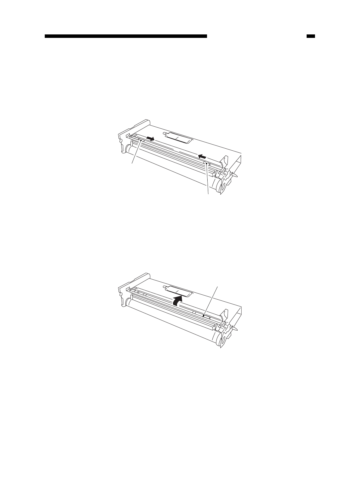
C. Primary Corona Assembly
1. Detaching the Primary Corona Assembly
1) Detach the drum unit.
2) Slide the lock qof the top of the drum unit in the direction of the arrow.
Figure 4-319
3) Detach the primary corona assembly unit wtogether with the holder while rotating it
in the direction of the arrow.
Figure 4-320
COPYRIGHT
©
1997 CANON INC. CANON NP6218 REV. 0 MAY 1997 PRINTED IN JAPAN (IMPRIME AU JAPON)
CHAPTER 4 IMAGE FORMATION SYSTEM
4-41
q
q
w
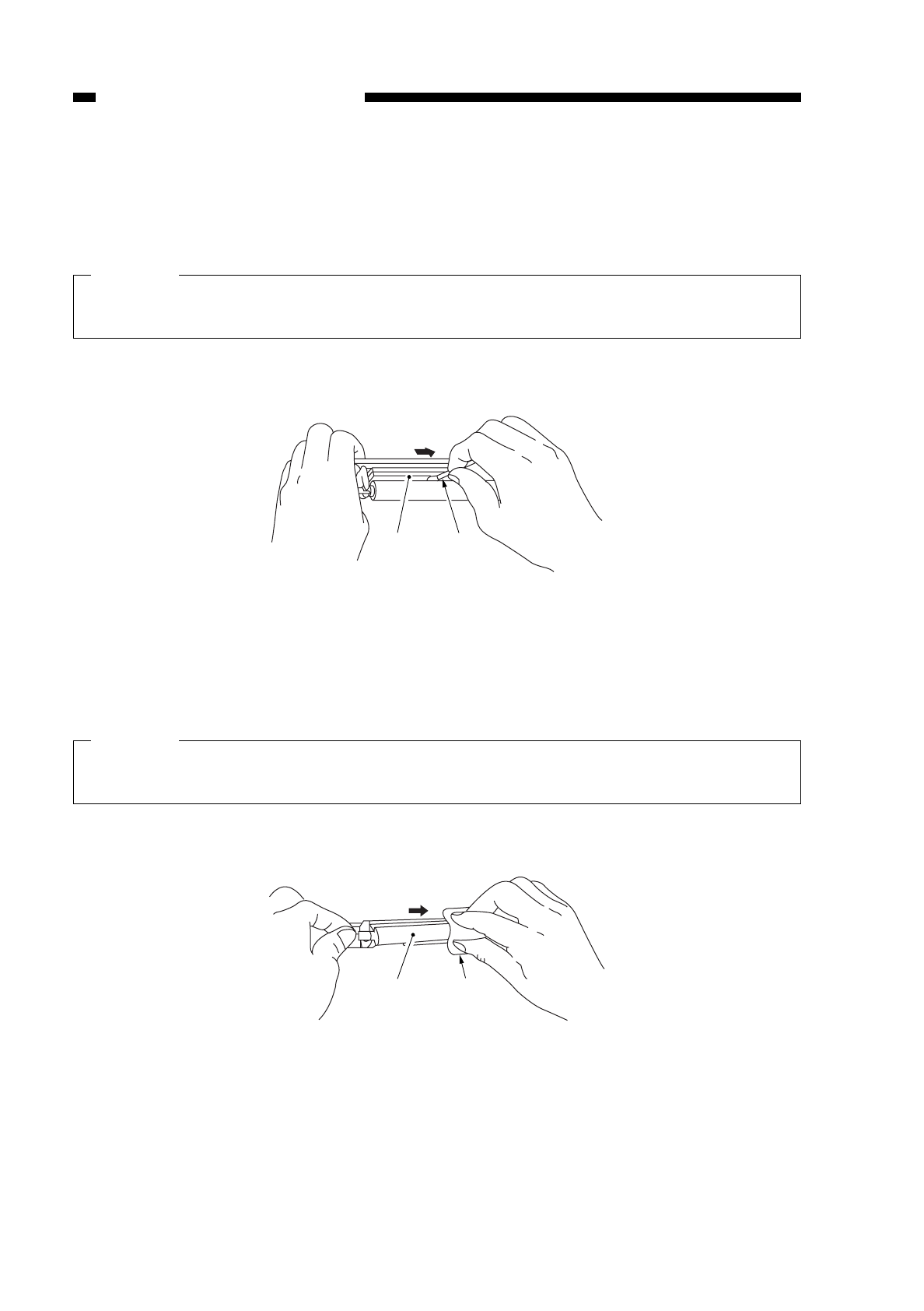
2. Cleaning the Cleaning Pad and the Primary Corona Roller
1) Detach the primary corona unit.
2) Place the primary corona assembly as shown in the figure, and clean the cleaning
pad ewith a cotton wad ror folded lint-free paper.
Caution:
• Dry-wipe only. Do not use water, alcohol, or solvent.
• Be sure to use strokes in one direction only.
Figure 4-321
3) Clean the primary charging roller twith lint-free paper ywhile rotating it.
Caution:
• Dry-wipe only. Do not use water, alcohol, or solvent.
• Be sure to use strokes in one direction only.
Figure 4-322
COPYRIGHT
©
1997 CANON INC. CANON NP6218 REV. 0 MAY 1997 PRINTED IN JAPAN (IMPRIME AU JAPON)
CHAPTER 4 IMAGE FORMATION SYSTEM
4-42
er
ty
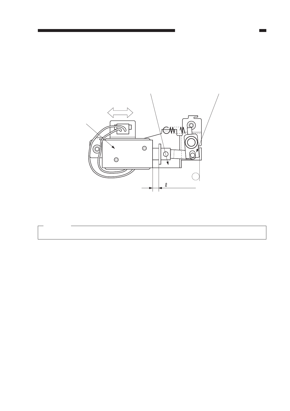
3. Positioning the Solenoid for the Primary Charging Roller
Make adjustments by loosening the two screws used to fix the solenoid ein place
and moving the solenoid einto the direction of arrow B so that
rin Figure 4-323 is 4.0
±0.2 mm when the joint qis butted against point aof the solenoid support w.
Figure 4-323
Caution:
You must make the adjustment whenever you have replaced the solenoid.
COPYRIGHT
©
1997 CANON INC. CANON NP6218 REV. 0 MAY 1997 PRINTED IN JAPAN (IMPRIME AU JAPON)
CHAPTER 4 IMAGE FORMATION SYSTEM
4-43
a
= 4.0 ± 0.2
B
wq
e
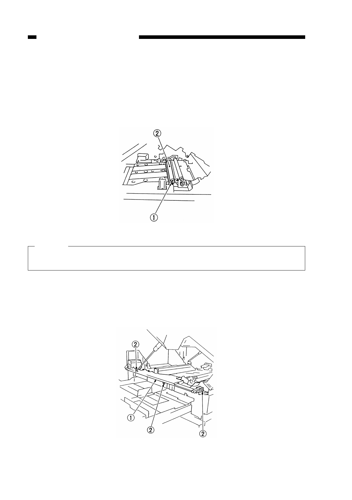
D. Transfer Charging Assembly
1. Detaching the Transfer Roller
1) Open the front door.
2) Open the copier’s top body.
3) Detach the static eliminator.
4) Detach the bushing q, and lift the transfer roller wto detach.
Figure 4-324
Caution:
Do not touch the surface of the roller.
Do not soil the surface of the roller.
2. Attaching the Drum Heater
1) Detach the front cover.
2) Open the copier’s top body by operating the copier open/close lever.
3) Detach the inside cover.
4) Remove the three fixing screws w, and detach the harness cover q.
Figure 4-325
COPYRIGHT
©
1997 CANON INC. CANON NP6218 REV. 0 MAY 1997 PRINTED IN JAPAN (IMPRIME AU JAPON)
CHAPTER 4 IMAGE FORMATION SYSTEM
4-44
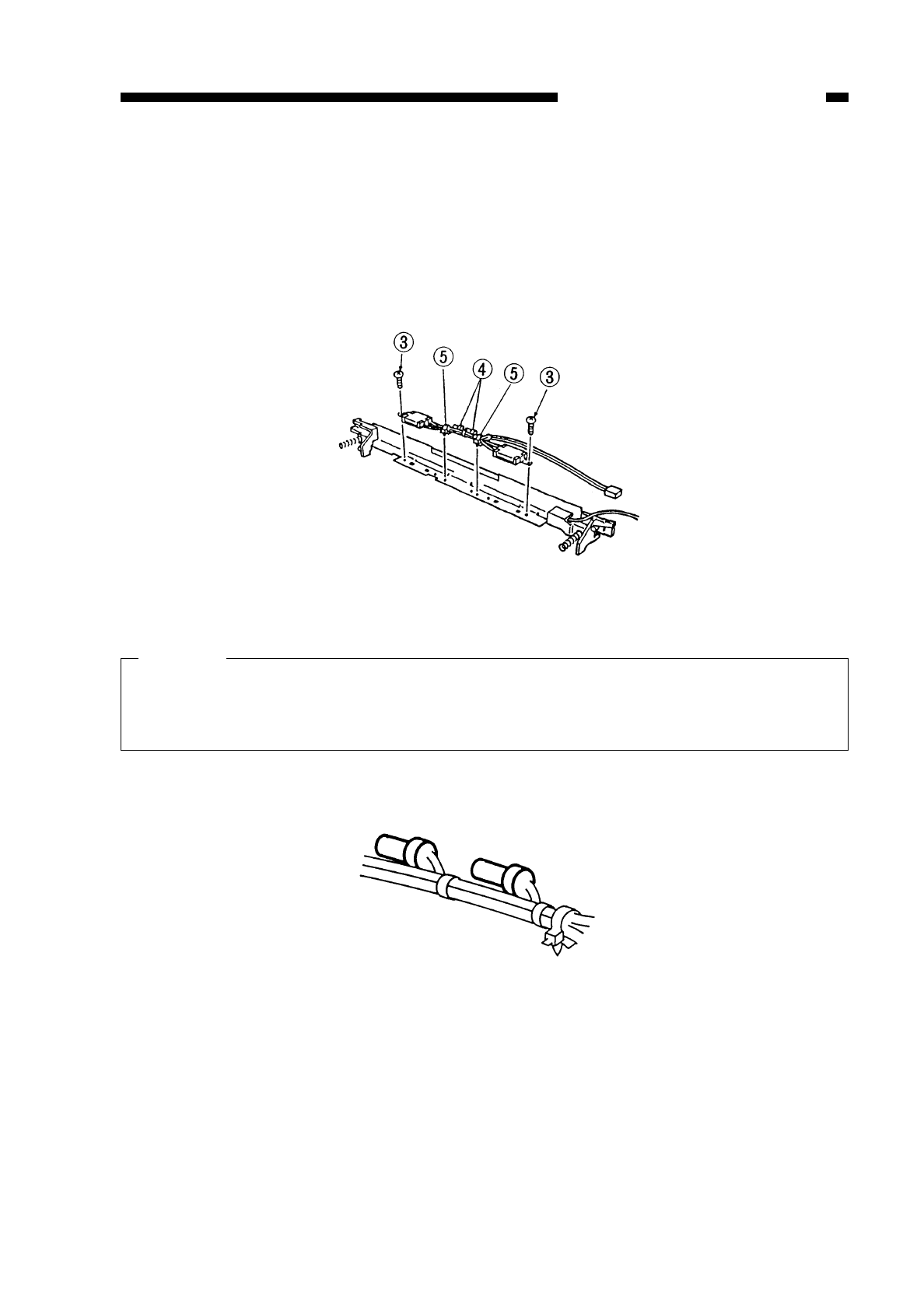
5) Detach the transfer roller and the static eliminator.
6) Detach the transfer guide.
7) While butting the two heaters against the transfer guide as shown in Figure 4-326, fix
them in place using two screws e; then, fix the harness using two harness bands r
(front, rear).
8) Fix the harness with two SK binders t(front, rear) in place, and insert it into the
transfer guide.
Figure 4-326
Caution:
When fixing the harness in place, make sure that the cap portions of the terminal
are alternated as shown in Figure 4-327; if bundled in parallel, the harness will
come into contact with the transfer roller.
Figure 4-327
COPYRIGHT
©
1997 CANON INC. CANON NP6218 REV. 0 MAY 1997 PRINTED IN JAPAN (IMPRIME AU JAPON)
CHAPTER 4 IMAGE FORMATION SYSTEM
4-45
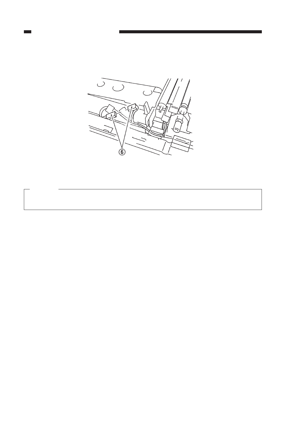
9) Connect the connector yas shown in Figure 4-328.
Figure 4-328
Caution:
Make sure that the spring at the rear is securely in the groove when attaching the
transfer guide to the copier after attaching the drum heater.
COPYRIGHT
©
1997 CANON INC. CANON NP6218 REV. 0 MAY 1997 PRINTED IN JAPAN (IMPRIME AU JAPON)
CHAPTER 4 IMAGE FORMATION SYSTEM
4-46

E. Developing System
1. Removing the Developing Assembly
1) Open the copier’s front door.
2) Operate the open/close lever to open the top body.
3) Turn the locking lever qclockwise to unlock the developing assembly.
4) Remove the screw w.
5) Pull the developing assembly eslowly to the front.
Figure 4-329
2. Removing the Blade Assembly
1) Remove the developing assembly from the copier.
2) Remove the four screws q, and remove the developing cover w.
Figure 4-330
COPYRIGHT
©
1997 CANON INC. CANON NP6218 REV. 0 MAY 1997 PRINTED IN JAPAN (IMPRIME AU JAPON)
CHAPTER 4 IMAGE FORMATION SYSTEM
4-47
1
32
w
q
q
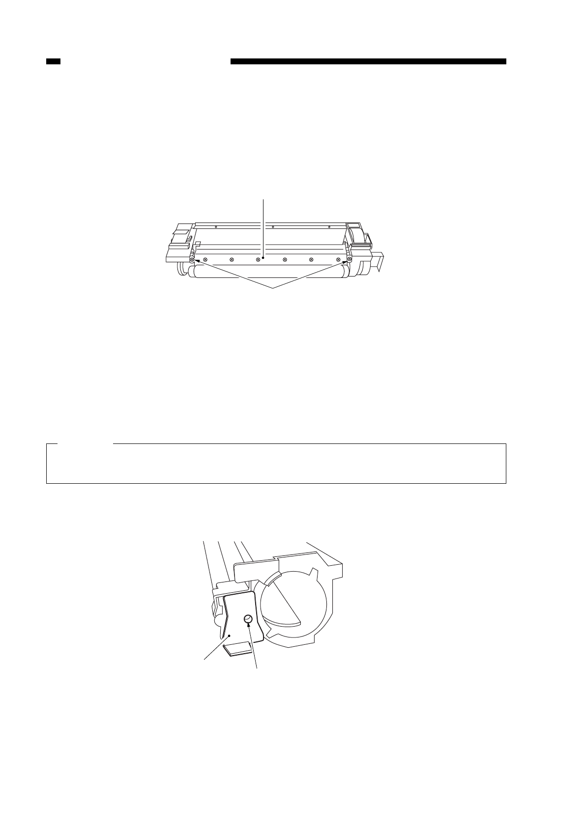
3) Place a newspaper or the like on the floor or a desk top, and pour out the toner from
the developing assembly.
4) Remove the two screws e, and remove the blade assembly* r.
* consisting of the blade and its mount.
Figure 4-331
3. Removing the Developing Cylinder Side Seal
1) Remove the developing assembly from the copier.
2) Remove the blade assembly.
Caution:
The blade must be installed at high precision. Do not remove it in the field. If
necessary, remove it intact on its mounting plate.
3) Remove the screw q, and remove the front cover w.
Figure 4-332
COPYRIGHT
©
1997 CANON INC. CANON NP6218 REV. 0 MAY 1997 PRINTED IN JAPAN (IMPRIME AU JAPON)
CHAPTER 4 IMAGE FORMATION SYSTEM
4-48
e
r
q
w
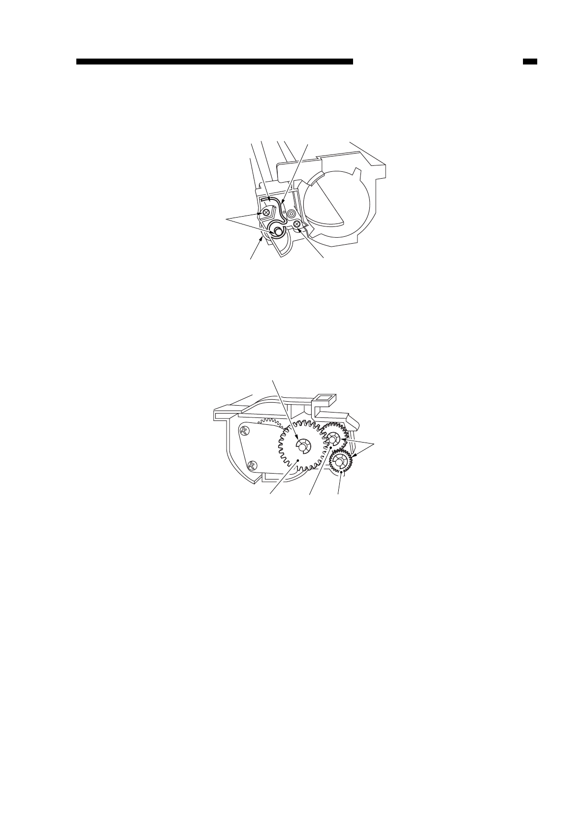
4) Remove the three screws e, and remove the terminal r, roll case t, and roll y.
Figure 4-333
5) Remove the three E-rings u, and gear i, gear o, and gear !0.
Figure 4-334
COPYRIGHT
©
1997 CANON INC. CANON NP6218 REV. 0 MAY 1997 PRINTED IN JAPAN (IMPRIME AU JAPON)
CHAPTER 4 IMAGE FORMATION SYSTEM
4-49
y
e
e
tr
u
u
!0
io
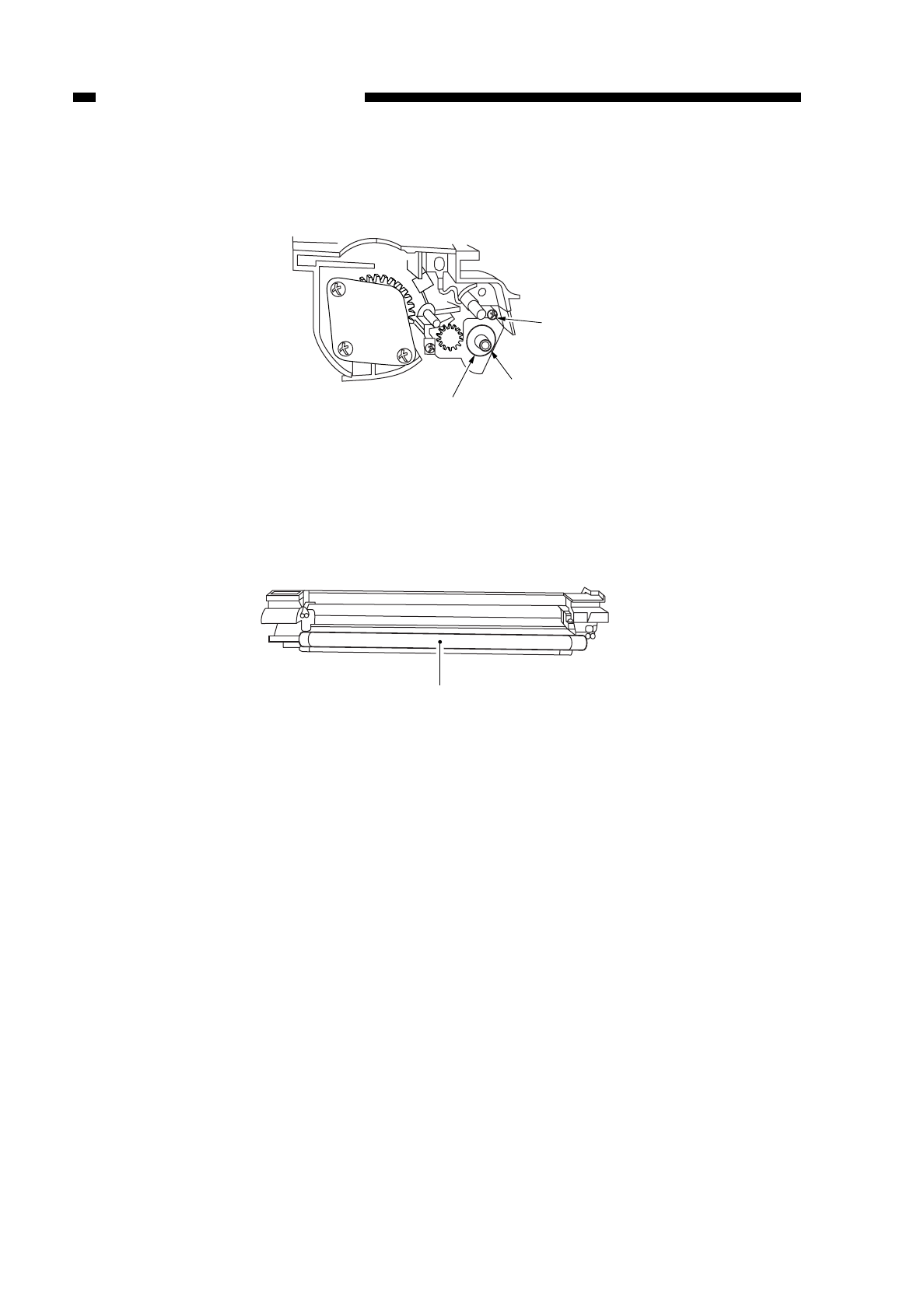
6) Remove the screw !1, and remove the butting roll !2 and roll case !3.
Figure 4-335
7) Remove the developing cylinder !4.
Figure 4-336
COPYRIGHT
©
1997 CANON INC. CANON NP6218 REV. 0 MAY 1997 PRINTED IN JAPAN (IMPRIME AU JAPON)
CHAPTER 4 IMAGE FORMATION SYSTEM
4-50
!1
!2
!3
!4
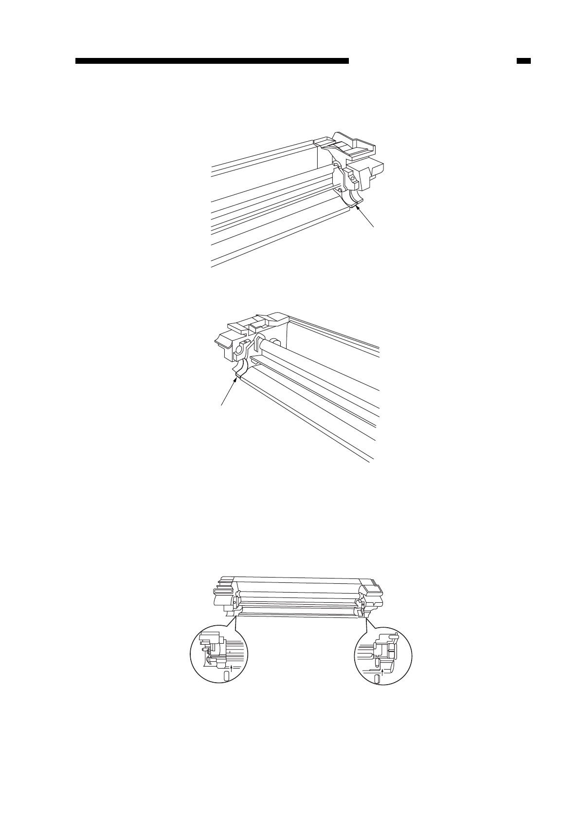
8) Remove the side seal !5. (both sides)
Figure 4-337
Figure 4-338
4. Installing the Side Seal and the Blade Assembly
1) Clean the area where the side seal will be installed with alcohol.
2) Attach the side seal as indicated in Figure 4-339.
Figure 4-339
COPYRIGHT
©
1997 CANON INC. CANON NP6218 REV. 0 MAY 1997 PRINTED IN JAPAN (IMPRIME AU JAPON)
CHAPTER 4 IMAGE FORMATION SYSTEM
4-51
!5
!5
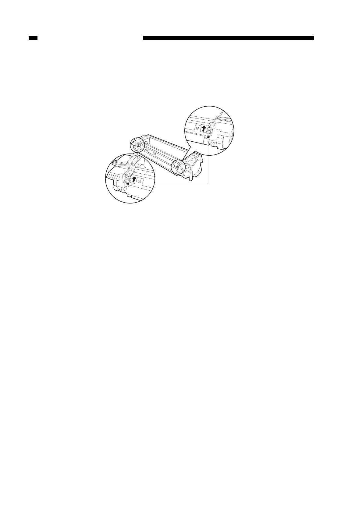
3) Check that the side seal and the container are in firm contact.
4) Push the developing blade unit attachment section all the way against the upper side
and secure it with the screw.
Figure 4-340
COPYRIGHT
©
1997 CANON INC. CANON NP6218 REV. 0 MAY 1997 PRINTED IN JAPAN (IMPRIME AU JAPON)
CHAPTER 4 IMAGE FORMATION SYSTEM
4-52
*Some spacers are glued top and
bottom in reverse; however, regardless
of the spacer positions, attach the
unit by pushing it all the way against
the Upper side.

COPYRIGHT
©
1997 CANON INC. CANON NP6218 REV. 0 MAY 1997 PRINTED IN JAPAN (IMPRIME AU JAPON)
CHAPTER 5
PICK-UP/FEEDING SYSTEM
I. PICK-UP/FEEDING SYSTEM ............5-1
A. Outline ...........................................5-1
II. PICK-UP OPERATION (COPIER)......5-3
A. Outline ...........................................5-3
B. Sequence of Operations (pick-up/
feeding assembly; A4, 2 copies) ...5-4
III. PICK-UP FROM THE CASSETTE
FEEDING MODULE-A2......................5-5
A. Pick-Up Operation .........................5-5
B. Sequence of Operations
(cassette 2; A4, 2 copies)..............5-6
IV. MULTIFEEDER...................................5-7
A. Outline ...........................................5-7
B. Identifying the Size of Paper on
the Multifeeder...............................5-8
C. Sequence of Operations
(multifeeder; A4, 2 copies) ............5-9
V. IDENTIFYING THE CASSETTE
SIZE....................................................5-10
VI. IDENTIFYING JAMS ..........................5-12
A. Pre-Registration Delay Jam...........5-12
B. Pre-Registration Timing Jam.........5-13
C. Pre-Registration Stationary Jam ...5-13
D. Separation Delay Jam ...................5-14
E. Separation Stationary Jam............5-14
F. Delivery Delay Jam........................5-15
G. Delivery Stationary Jam ................5-15
VII. DISASSEMBLY AND ASSEMBLY ......5-16
A. Pick-Up Assembly .........................5-16
B. Multifeeder Assembly ....................5-23
C. Registration Roller Assembly ........5-31
D. Feeding Assembly.........................5-34
E. Cassette Unit.................................5-36
This chapter explains the principles used from when copy paper is picked up to when a copy is
delivered in view of the functions of electrical and mechanical units and in relation to their timing of
operation. It also shows how these units may be disassembled/assembled and adjusted.
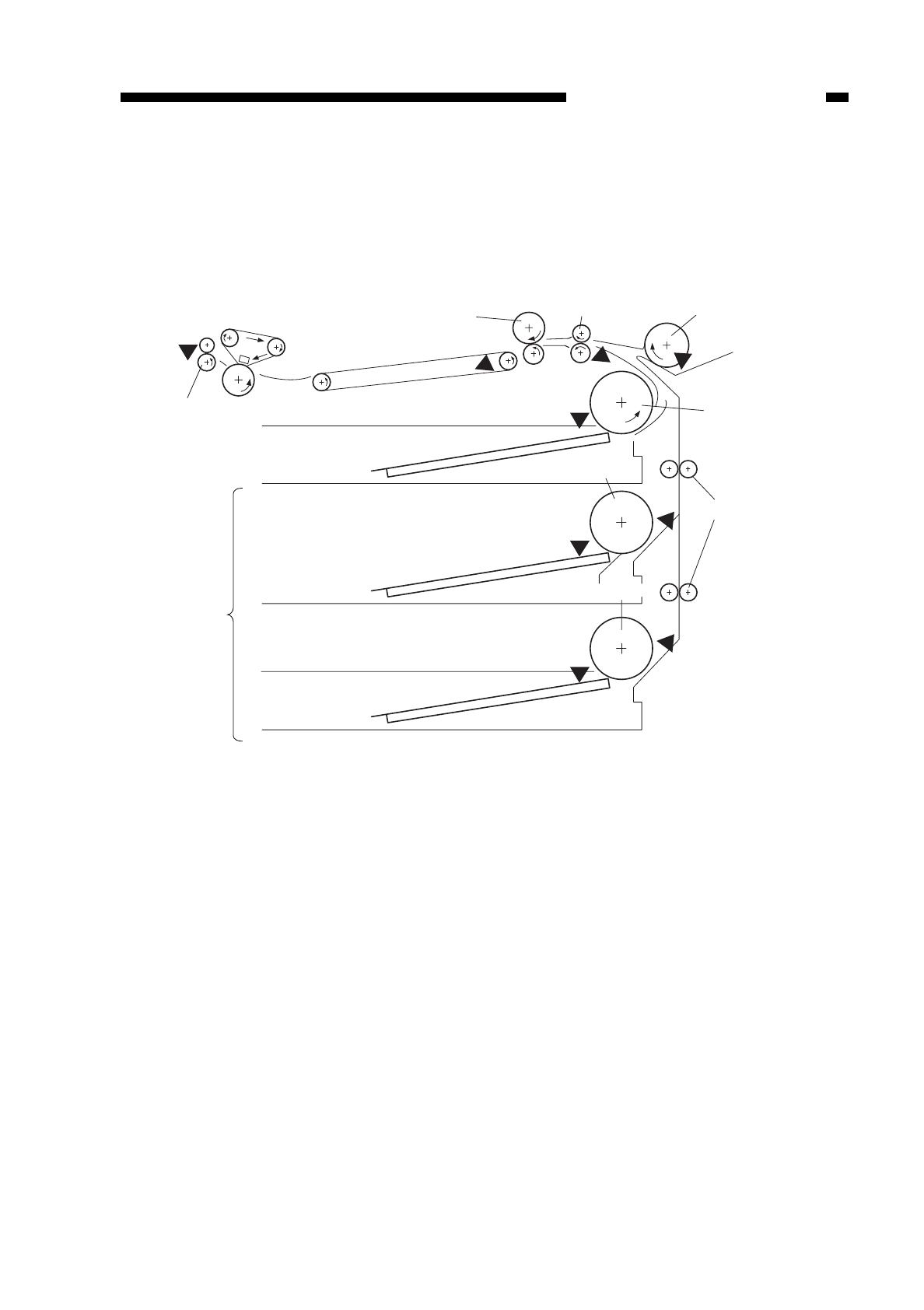
I. PICK-UP/FEEDING SYSTEM
Figure 5-101
A. Outline
The NP6218 uses center reference, in which copy paper is moved through the center
of the pick-up/feeding path for stable pick-up/feeding operation.
Pick-up operation may be the cassette 1 pick-up from the copier, cassette 2/3 pick-
up from the Cassette feeding Module-B2/A2 and multifeeder pick-up.
When making copies, copy paper picked up from the cassette 1/2/3 or multifeeder is
controlled by the registration roller so that the leading edge of the image on
photosensitive drum matches with the leading edge of the copy paper; the paper is then
sent to the copy tray through the transfer, separation, feeding, fixing, and delivery
assemblies.
COPYRIGHT
©
1997 CANON INC. CANON NP6218 REV. 0 MAY 1997 PRINTED IN JAPAN (IMPRIME AU JAPON)
CHAPTER 5 PICK-UP/FEEDING SYSTEM
5-1
Registration
roller Multifeeder
pick-up
roller
Pick-up
roller
Vertical path roller
Pick-up clutch
PS5
PS1cu
PS3cu
PS4cu
PS2cu
PS4
PS6
PS7
PS8
Pick-up roller
Pick-up roller
Photosensitive
drum
Feeding belt
Fixing assembly
Delivery roller
Cassette 1
Cassette 2
Cassette 3
Accesorry

Table 5-101
COPYRIGHT
©
1997 CANON INC. CANON NP6218 REV. 0 MAY 1997 PRINTED IN JAPAN (IMPRIME AU JAPON)
CHAPTER 5 PICK-UP/FEEDING SYSTEM
5-2
Sensor No.
PS4
PS5
PS6
PS7
PS8
PS1CU
PS2CU
PS3CU
PS4CU
Name
Multifeeder paper sensor
Cassette paper sensor
Registration sensor
Separation sensor
Delivery sensor
Cassette 2 vertical path sensor (Accessory)
Cassette 2 paper sensor (Accessory)
Cassette 3 vertical path sensor (Accessory)
Cassette 3 paper sensor (Accessory)
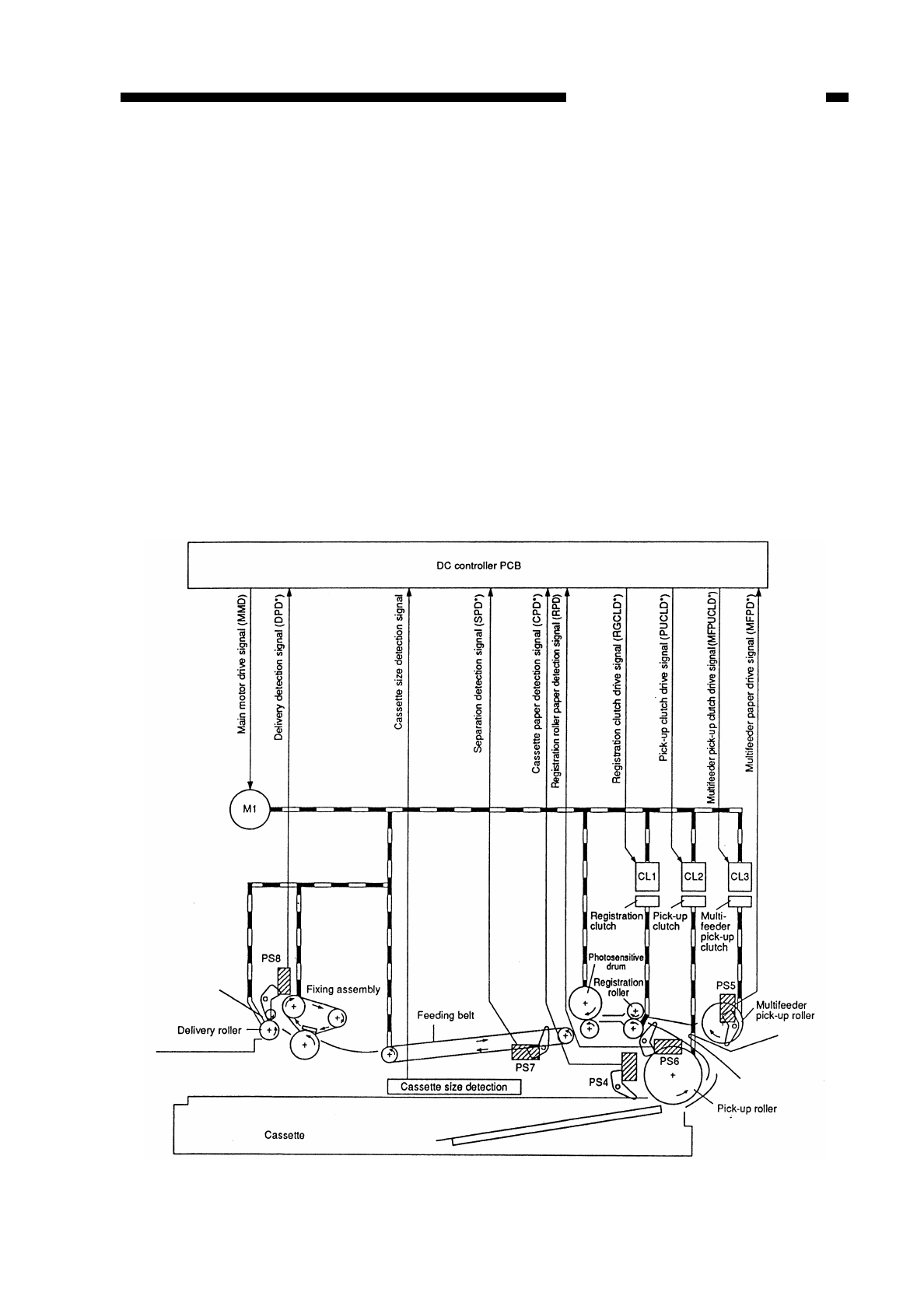
II. PICK-UP OPERATION (COPIER)
A. Outline
When the pick-up clutch (CL2 or CL3) turns on while the main motor (M1) is rotating,
the pick-up roller rotates to move paper as far as the registration roller.
The copy paper is controlled so that its leading edge and the leading edge of the
image on the photosensitive drum match; then, it is moved through the transfer
assembly, feeding assembly, fixing assembly, and delivery assembly to reach the copy
tray.As many as three photointerrupters (PS6, PS7, PS8) are provided along the paper
path, turning on the Jam indicator on the control panel when jams are identified in terms
of whether paper has reached or has moved past the respective sensors within a specific
period of time.
The presence/absence of paper inside the cassette or the multifeeder is monitored
by separate photointerpreters (PS4, PS5); when the absence of paper is identified, the
Paper indicator is flashed on the control panel.
Figure 5-201
COPYRIGHT
©
1997 CANON INC. CANON NP6218 REV. 0 MAY 1997 PRINTED IN JAPAN (IMPRIME AU JAPON)
CHAPTER 5 PICK-UP/FEEDING SYSTEM
5-3
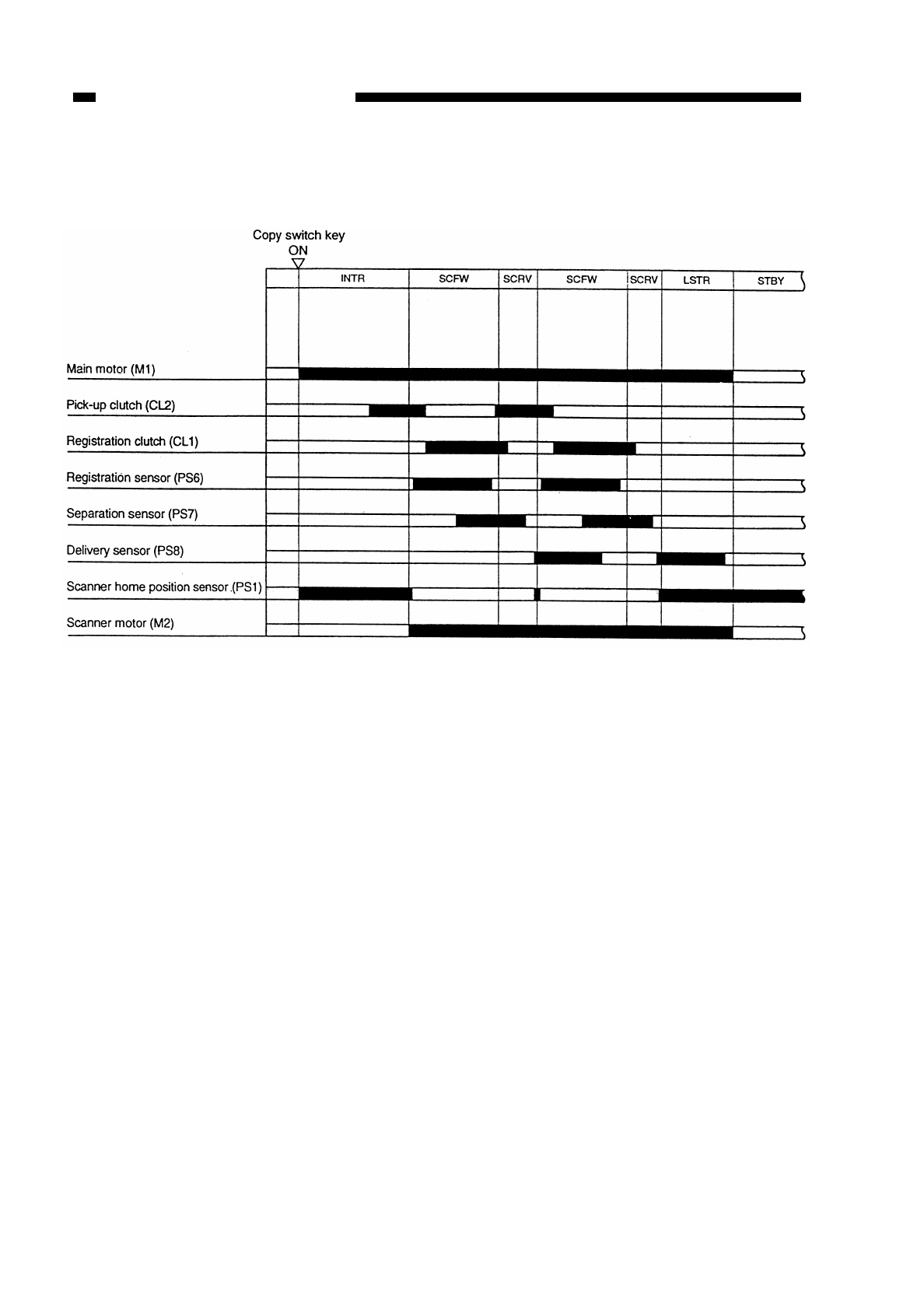
B. Sequence of Operations (pick-up/feeding assembly; A4, 2
copies)
Figure 5-202
COPYRIGHT
©
1997 CANON INC. CANON NP6218 REV. 0 MAY 1997 PRINTED IN JAPAN (IMPRIME AU JAPON)
CHAPTER 5 PICK-UP/FEEDING SYSTEM
5-4
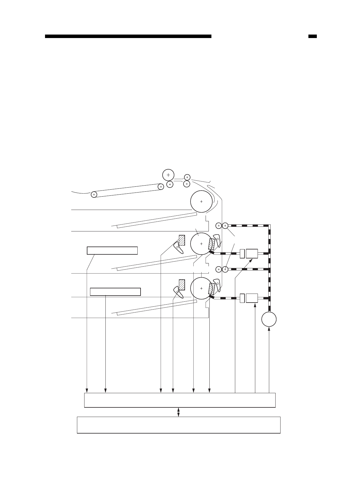
III. PICK-UP FROM THE CASSETTE FEEDING
MODULE-A2
A. Pick-Up Operation
When the pick-up clutch (CL1cu, CL2cu) turns on while the cassette unit motor
(M1cu), the pick-up roller starts to rotate to pick up copy paper; the paper is then moved
to the registration roller by the vertical path roller. (The sequence that follows is the same
as when paper is picked up from the cassette in the copier.)
For pick-up operation from the cassette feeding unit, pick-up sensors (PS1cu,
PS3cu) are used to check the arrival of paper, thereby deciding when to turn off the pick-
up roller according to the size of paper.
Figure 5-301
COPYRIGHT
©
1997 CANON INC. CANON NP6218 REV. 0 MAY 1997 PRINTED IN JAPAN (IMPRIME AU JAPON)
CHAPTER 5 PICK-UP/FEEDING SYSTEM
5-5
M1cu
Cassett e 2
Cassett e 3
PS2cu
PS4cu
PS1cu
CL1cu
CL2cu
PS3cu
Pick-up roller
Casette 2 size detection
Casette 3 size detection
Pick-up roller
Vertical path roller
Pick-up clutch
Cassette drive PCB
Cassette 2 size detection signal
Cassette 3 size detection signal
Cassette 2 paper detection signal (C2PD*)
Cassette 3 paper detection signal (C3PD*)
Cassette 2 vertical path detection signal
(C2VPD)
Cassette 3 vertical path detection signal
(C3VPD)
Cassette 2 pick-up clutch drive signal (C2PUCLD*)
Cassette 3 pick-up clutch drive signal (C3PUCLD*)
Cassette feeding unit motor drive
signal (CMD)
DC controller PCB
Cassette
unit motor
Pick-up clutch
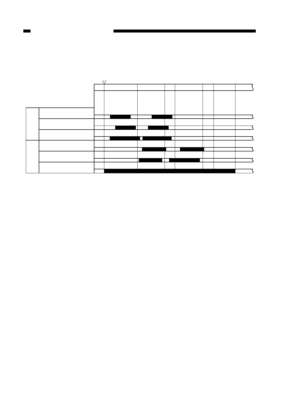
B. Sequence of Operations (cassette 2; A4, 2 copies)
Figure 5-302
COPYRIGHT
©
1997 CANON INC. CANON NP6218 REV. 0 MAY 1997 PRINTED IN JAPAN (IMPRIME AU JAPON)
CHAPTER 5 PICK-UP/FEEDING SYSTEM
5-6
INTR SCFW SCRV SCFW SCRV LSTR STBY
Copy Start key
ON
Cassette
feeding
unit
Copier
Cassette 2 pick-up clutch
(CL1cu)
Cassette 2 vertical path sensor
(PS1cu)
Cassette feeding unit motor
(M1cu)
Registration clutch (CL1)
Registration sensor (PS6)
Main motor (M1)
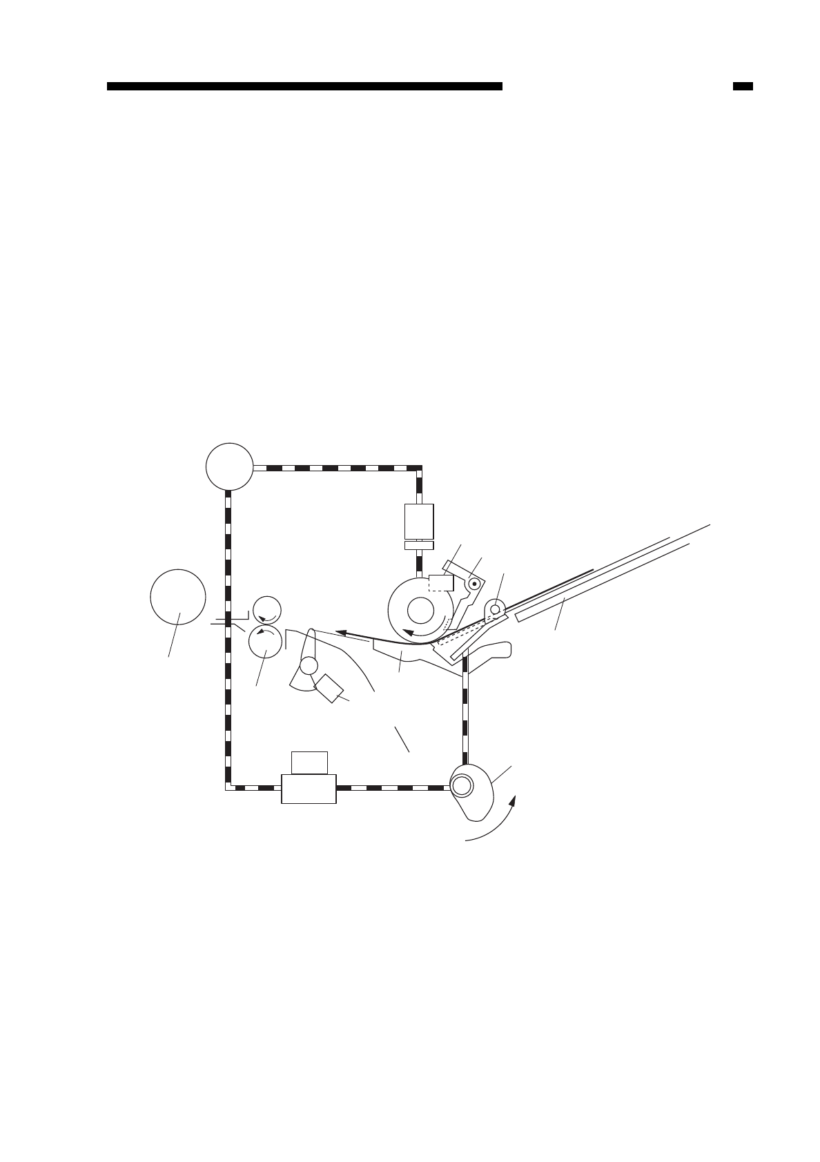
IV. MULTIFEEDER
A. Outline
The multifeeder is designed to pick up paper loaded on its tray and is capable of
continuous pick-up operation.
Paper on the tray is detected by the multifeeder sensor (PS5).
Paper loaded on the tray is butted against the pick-up roller by the paper guide plate;
the drive from the main motor (M1) is transmitted to the pick-up roller through a clutch to
rotate the pick-up roller.
By the work of the pick-up roller and the separation pad, a single sheet of copy paper
is forwarded to the registration roller.
The series of operations is executed for each pick-up operation.
Figure 5-401
COPYRIGHT
©
1997 CANON INC. CANON NP6218 REV. 0 MAY 1997 PRINTED IN JAPAN (IMPRIME AU JAPON)
CHAPTER 5 PICK-UP/FEEDING SYSTEM
5-7
M1
PS5
PS6
Multifeeder pick-up
clutch
Multifeeder paper sensor
Paper sensor lever
Paper guide plate
Multifeeder tray
Paper guide plate cam
Photosensitive
drum Registration
roller
Multifeeder pick-up
solenoid
Registration roller
paper sensor
Separation pad
SL2
Spring
clutch
CL3
Main motor
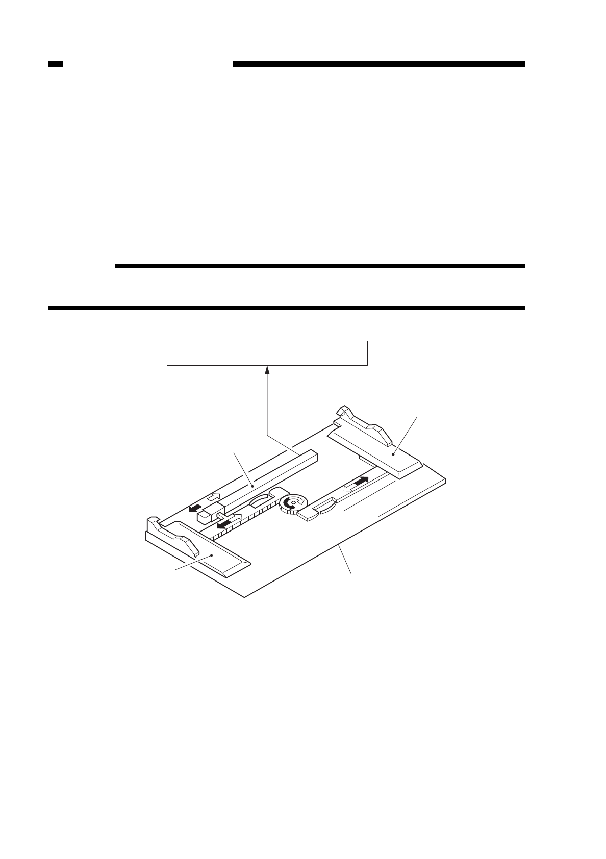
B. Identifying the Size of Paper on the Multifeeder
The width of copy paper is identified by a variable resistor (VR1) which operates in
response to the location of the slide guide, which is adjusted by the user to suit the size
of paper.
The identified width of copy paper is used for blank exposure control.
The length of paper when the multifeeder is used is identified by the period of time
during which the registration sensor (PS6) remains on.
The data collected in such a way is used to control the length of blank exposure,
activation of the registration roller, and high voltage.
Reference:
The maximum length of paper is 432 mm (LDG size); paper longer than this will
lead to a jam.
Figure 5-402
COPYRIGHT
©
1997 CANON INC. CANON NP6218 REV. 0 MAY 1997 PRINTED IN JAPAN (IMPRIME AU JAPON)
CHAPTER 5 PICK-UP/FEEDING SYSTEM
5-8
Slide guide (Front) Multifeeder tray
Slide guide (rear)
DC controller PCB
Variable resistor (VR1)
Multifeeder paper
width detection
(MFPWD)
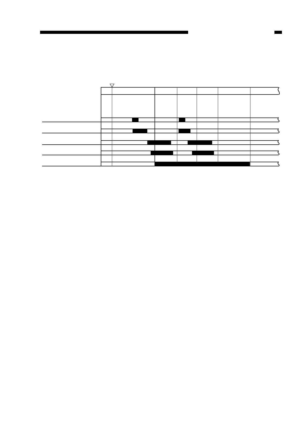
C. Sequence of Operations (multifeeder; A4, 2 copies)
Figure 5-403
COPYRIGHT
©
1997 CANON INC. CANON NP6218 REV. 0 MAY 1997 PRINTED IN JAPAN (IMPRIME AU JAPON)
CHAPTER 5 PICK-UP/FEEDING SYSTEM
5-9
INTR SCFW SCRV SCFW SCRV LSTR
Copy Start key
ON
Multifeeder pick-up solenoid
(SL2)
Multifeeder pick-up clutch
(CL3)
Pre-registration sensor (PS6)
Registration clutch (CL2)
Scanner motor (M2)
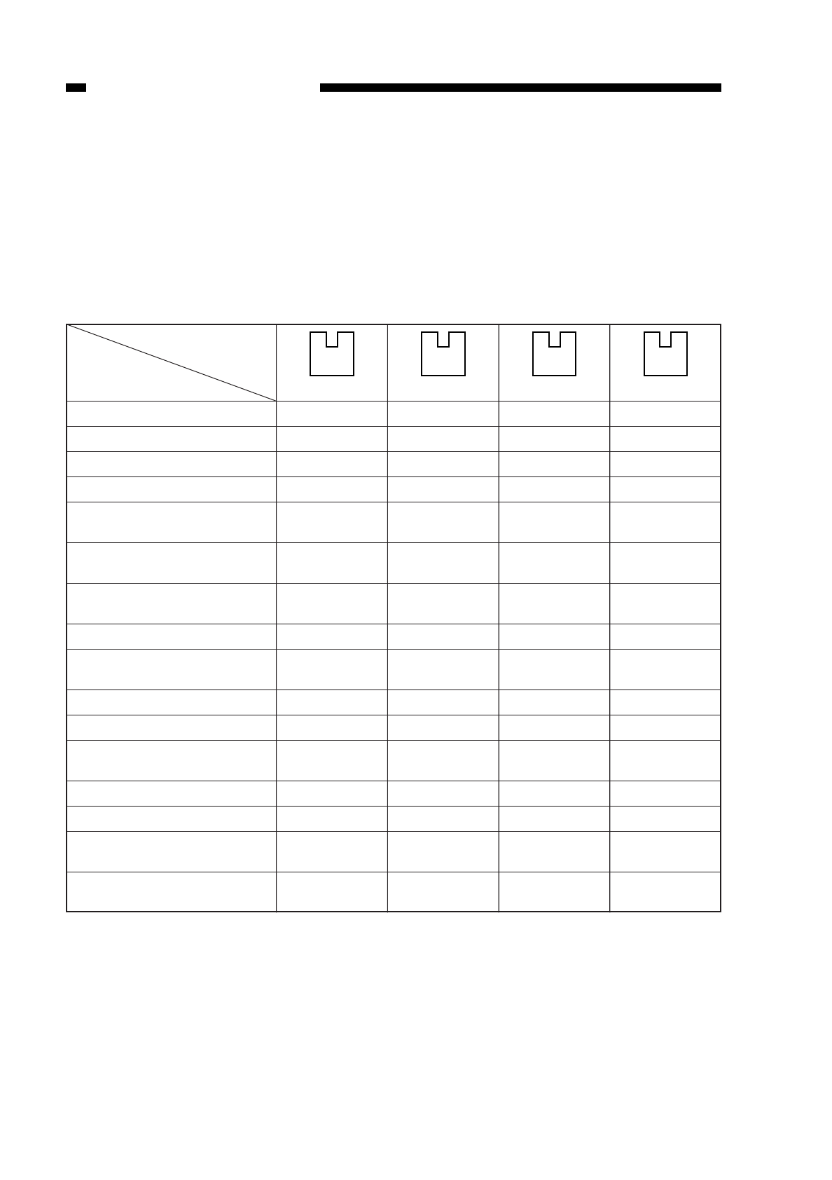
V. IDENTIFYING THE CASSETTE SIZE
When a cassette is set in the cassette holder, appropriate photointerrupters (Q651,
Q652, Q653, Q654) turn on or off.
The microprocessor on the DC controller PCB identifies the presence/absence of a
cassette based on the combinations of the photointerrupters which are either on or off
(Table 5-501); accordingly, the microprocessor controls where the scanner must be
reversed or when to execute blank exposure.
(unit: mm)
1: photointerrupter is blocking light.
0: photointerrupter is not blocking light.
*size may be stored; must be within the range specified in mm; for details, see p. 10-
43.
Table 5-501
(right)
0
1
0
1
0
1
0
1
0
1
0
1
0
1
0
1
0
0
1
1
0
0
1
1
0
0
1
1
0
0
1
1
0
0
0
0
1
1
1
1
0
0
0
0
1
1
1
1
(Left)
0
0
0
0
0
0
0
0
1
1
1
1
1
1
1
1
COPYRIGHT
©
1997 CANON INC. CANON NP6218 REV. 0 MAY 1997 PRINTED IN JAPAN (IMPRIME AU JAPON)
CHAPTER 5 PICK-UP/FEEDING SYSTEM
5-10
Arrangement
Cassette size
No cassette
B5R (182
×257)
A4 (297 ×220)
A3 (297 ×420)
Mini (STMTR) 5.5" ×8.5"
(148 ×216)
Legal 8.5" ×14"
(356 ×216)
Letter 11" ×8.5"
(279 ×216)
A4R (210 ×297)
Letter R 8.5" ×11"
(216 ×279)
A5R (149 ×218)
A5 (218 ×149)
Mini-R (STMT) 8.5" ×5.5"
(216 ×148)
B5 (257 ×182)
B4 (364 ×257)
Ledger 11" ×17"
(182 ×257)
*U
(182 ~ 283 ×198 ~ 354)
Q651
Q652
Q653
Q654
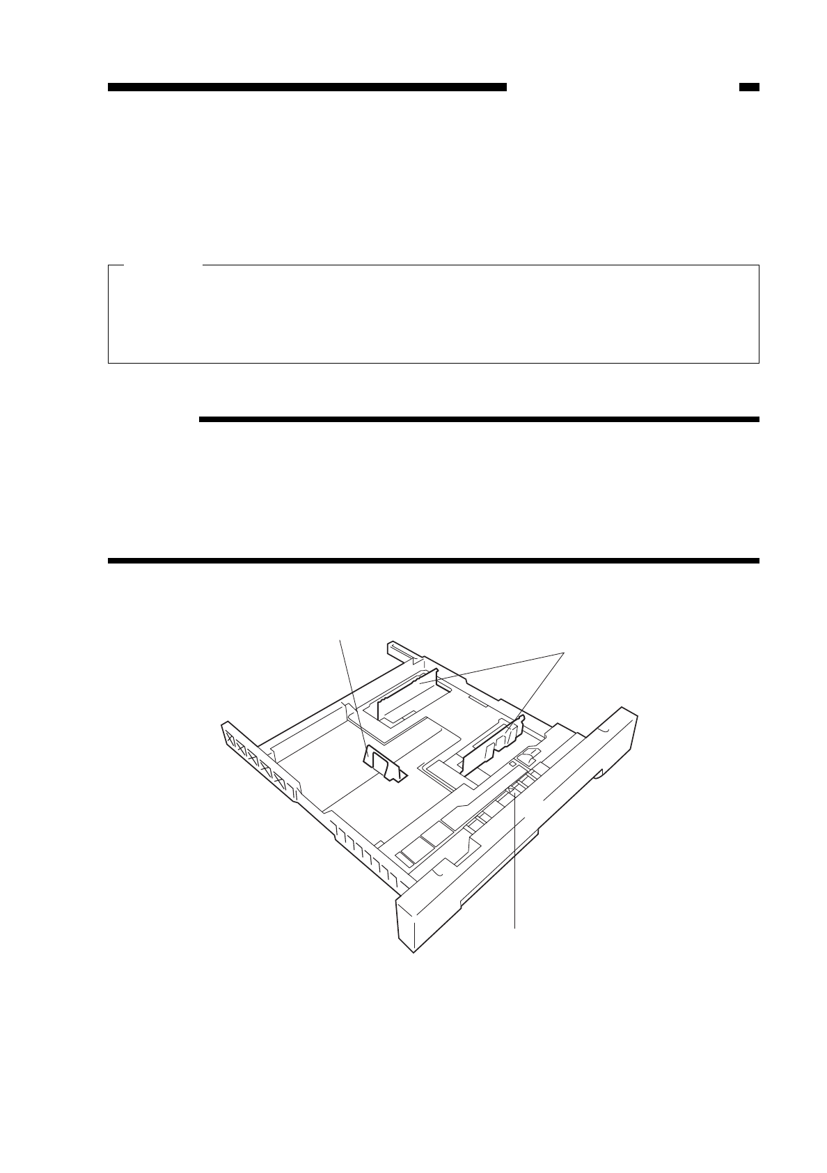
To change the cassette size, you must not only move the guide plate (horizontal,
vertical) inside the cassette to suit the copy paper but also move the paper size lever
located toward the front of the cassette (Figure 5-501) to the left or right so that the arrow
points to the appropriate paper size.
Caution:
A discrepancy between the size set by the paper size lever and the size of copy
paper will result in jams or soiling because of the wrong copying sequence.
Advise the user to be sure to match the size set by the paper size lever and the size
of copy paper.
Reference:
Paper size configurations differ from area to area; however, you may still make sure
of a specific copy control sequence for the size of paper that does not fall under the
respective category—the size, nevertheless, will not be indicated on the display.
For instance, you may use LTR paper for a metric model. (The paper size lever, in
this case, will be set to LTR.) This arrangement causes the copier to execute the
copying sequence intended for LTR copies.
Figure 5-501
COPYRIGHT
©
1997 CANON INC. CANON NP6218 REV. 0 MAY 1997 PRINTED IN JAPAN (IMPRIME AU JAPON)
CHAPTER 5 PICK-UP/FEEDING SYSTEM
5-11
Guide plate (vertical)
Paper size lever
Guide plate (horizontal)
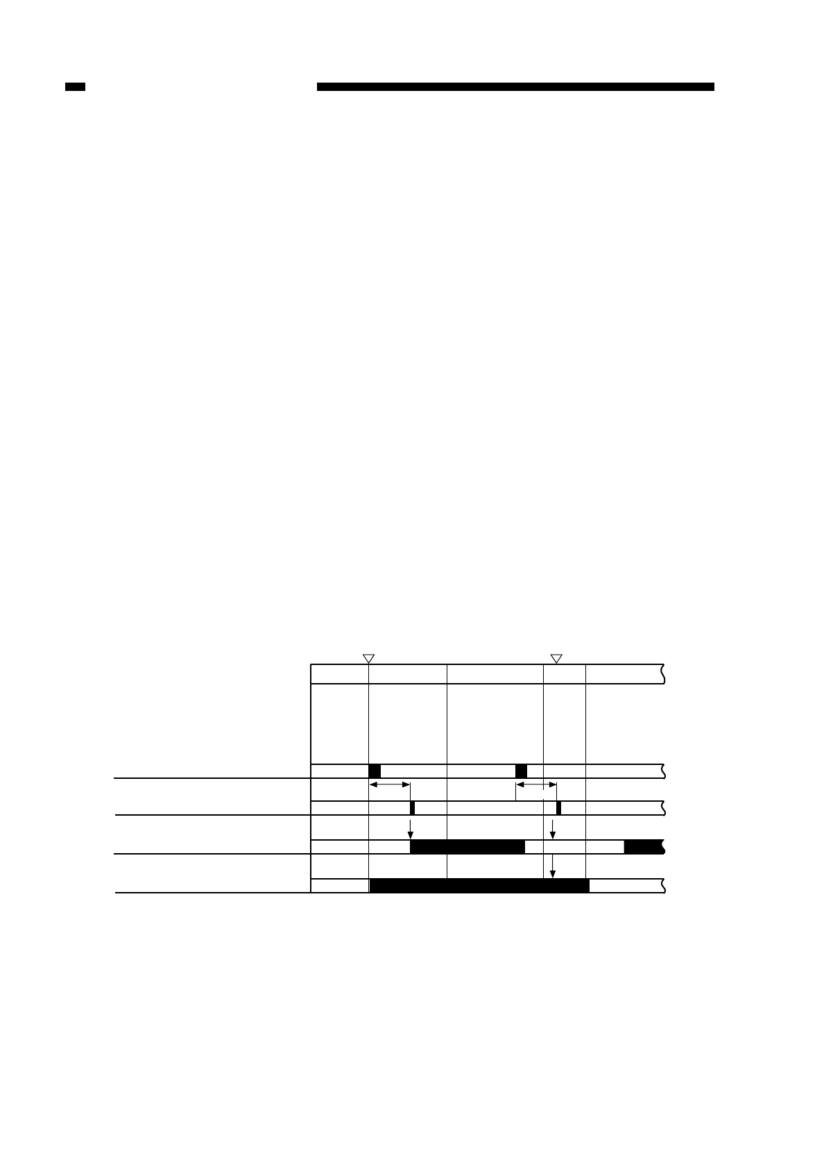
VI. IDENTIFYING JAMS
As many as six (3 in the cassette feeding unit) are used to monitor the movement of
copy paper:
• registration sensor (PS6)
• separation sensor (PS7)
• delivery sensor (PS8)
A jam is identified in terms of the presence/absence of paper at the respective
sensors at such times as stored in the microprocessor.
The copier has a mechanism to remember how many copies remain to be made after
a jam and the current copy mode; it still retains such information even when it is deprived
of power by opening of the front cover.
The microprocessor has the jam detection sequence that is described below and,
further, identifies the presence of paper as detected by a sensor at power-on.
When the copier identifies a jam, it immediately stops the ongoing copying operation
and cuts off the power to the fixing heater (H1); at the same time, it flashes the Jam
indicator on the control panel and flashes also any of the location indicator.
The activation of the jam detection mechanism will not increment the copy count for
the copy which has jammed.
A. Pre-Registration Delay Jam
Copy paper does not reach the registration sensor (PS6) within a specific period of
time after the pick-up clutch (CL2) has gone on because of feeding problems.
Figure 5-601 Pre-Registration Delay Jam Sequence
COPYRIGHT
©
1997 CANON INC. CANON NP6218 REV. 0 MAY 1997 PRINTED IN JAPAN (IMPRIME AU JAPON)
CHAPTER 5 PICK-UP/FEEDING SYSTEM
5-12
Main motor (M1)
Jam check
STBY INTR SCRV SCFWSCFW
Pck-up clutch (CL2)
Registration sensor (PS6)
1.5 sec
Error
Copy Start key
ON Jam indicator
(flashing)
Normal
1.5 sec
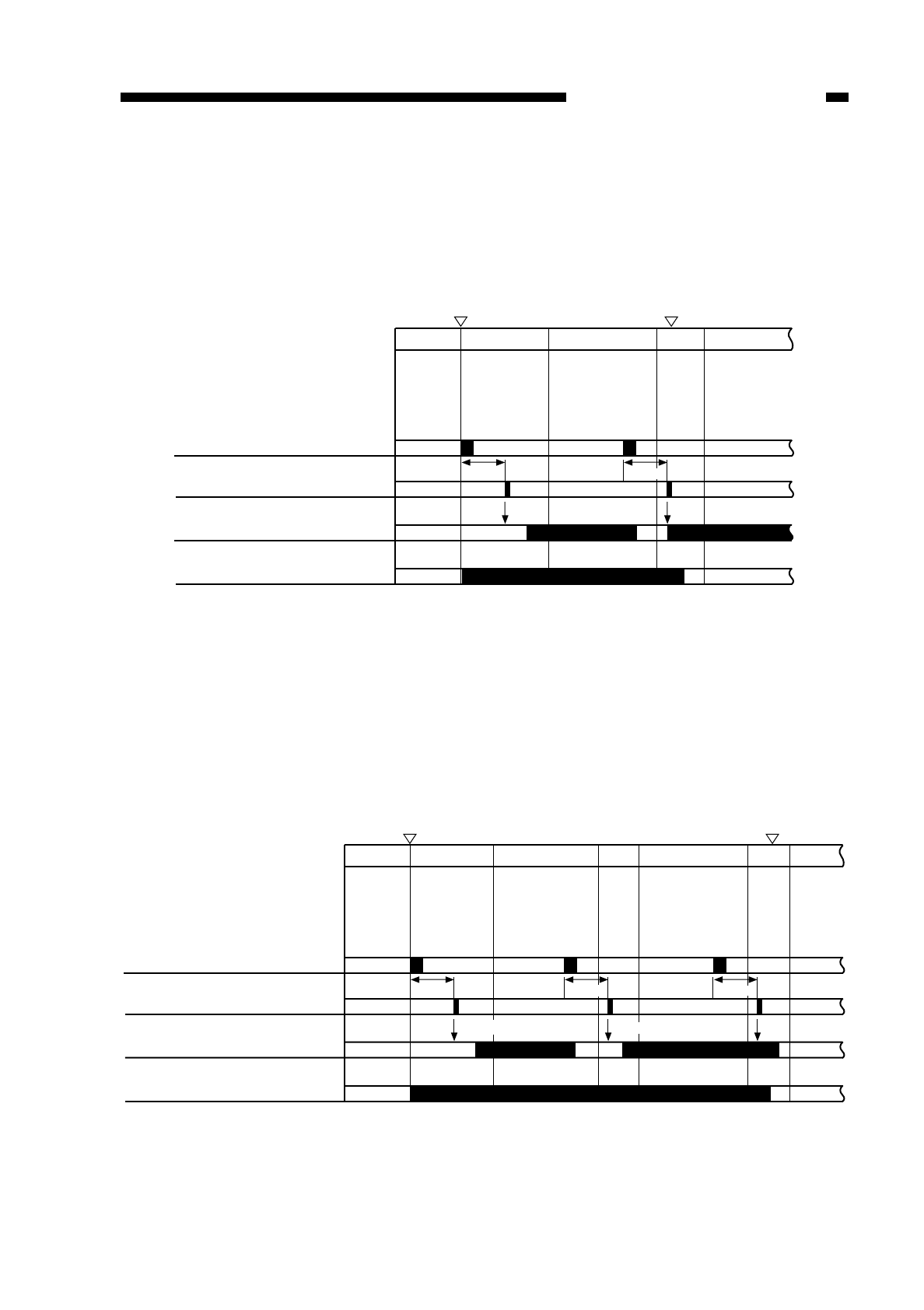
B. Pre-Registration Timing Jam
Copy paper reaches the registration sensor (PS6) before a specific period of time
after the pick-up clutch (CL2) has gone on because of feeding problems.
Figure 5-602 Pre-Registration Timing Jam Sequence
C. Pre-Registration Stationary Jam
Copy paper does not move past the registration sensor (PS6) within a specific period
of time after the pick-up clutch (CL2) has turned on because of feeding problems.
Figure 5-603 Pre-Registration Stationary Jam Sequence
COPYRIGHT
©
1997 CANON INC. CANON NP6218 REV. 0 MAY 1997 PRINTED IN JAPAN (IMPRIME AU JAPON)
CHAPTER 5 PICK-UP/FEEDING SYSTEM
5-13
Main motor (M1)
Jam check
STBY INTR SCRV SCFWSCFW
Pck-up clutch (CL2)
Registration sensor (PS6)
0.8 sec
Copy Start key
ON Jam indicator
(flashing)
Normal Error
0.8 sec
Main motor
Jam check
STBY INTR SCRV SCRVSCFWSCFW
Pck-up clutch (CL2)
Registration sensor (PS6)
0.8 sec
Copy Start key
ON Jam indicator
(flashing)
Error
0.8 sec
Normal
0.8 sec
Normal
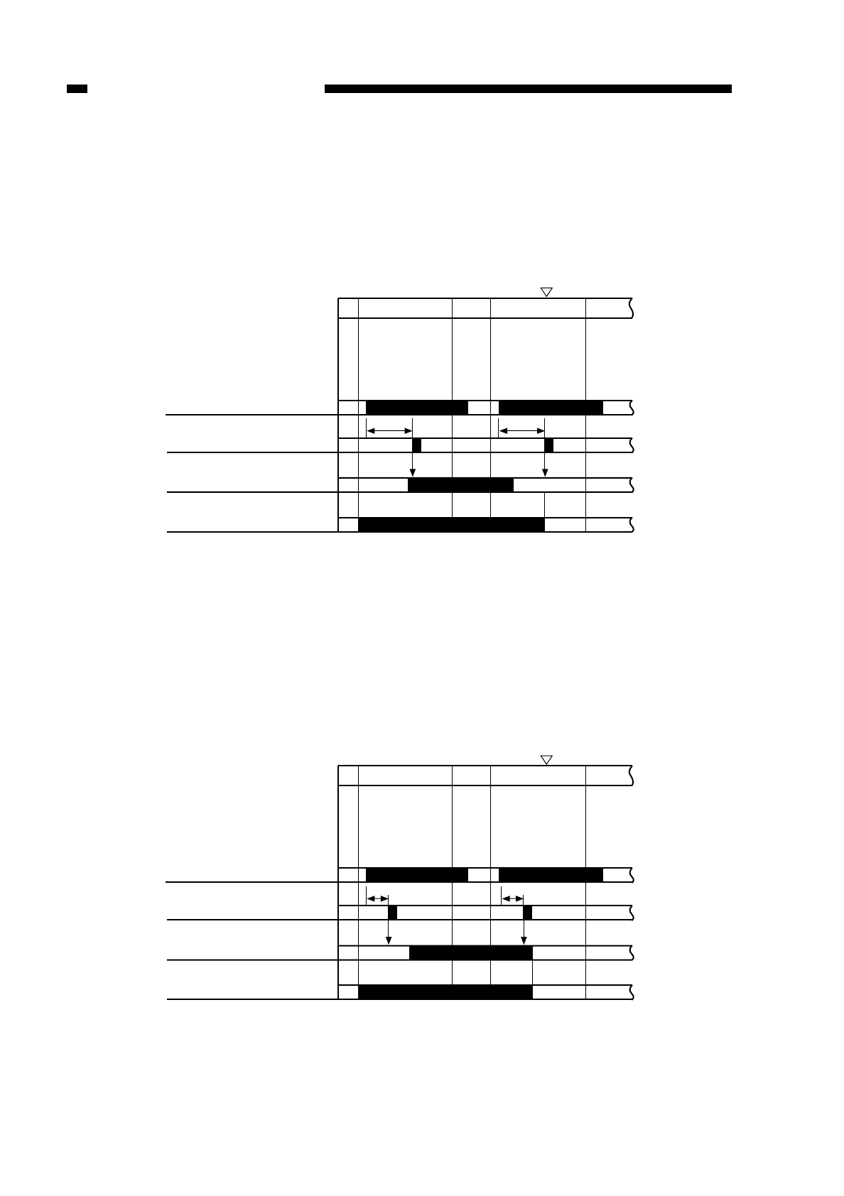
D. Separation Delay Jam
Copy paper does not reach the separation sensor (PS7) within a specific period of
time after the registration clutch (CL1) has gone on because of feeding problems.
Figure 5-604 Separation Delay Jam Sequence
E. Separation Stationary Jam
Copy paper does not move past the separation sensor (PS7) within a specific period
of time after the registration clutch (CL1) has gone on because of feeding problems.
Figure 5-605 Separation Stationary Jam Sequence
COPYRIGHT
©
1997 CANON INC. CANON NP6218 REV. 0 MAY 1997 PRINTED IN JAPAN (IMPRIME AU JAPON)
CHAPTER 5 PICK-UP/FEEDING SYSTEM
5-14
Main motor (M1)
Jam check
SCRV SCRVSCFWSCFW
Registration clutch (CL1)
Separation sensor (PS7)
Jam indicator
(flashing)
Normal
1.1 sec
Error
1.1 sec
Main motor (M1)
Jam check
SCRV SCRVSCFWSCFW
Registration clutch (CL1)
Separation sensor (PS7)
Jam indicator
(flashing)
Normal
0.3 sec
Error
0.3 sec
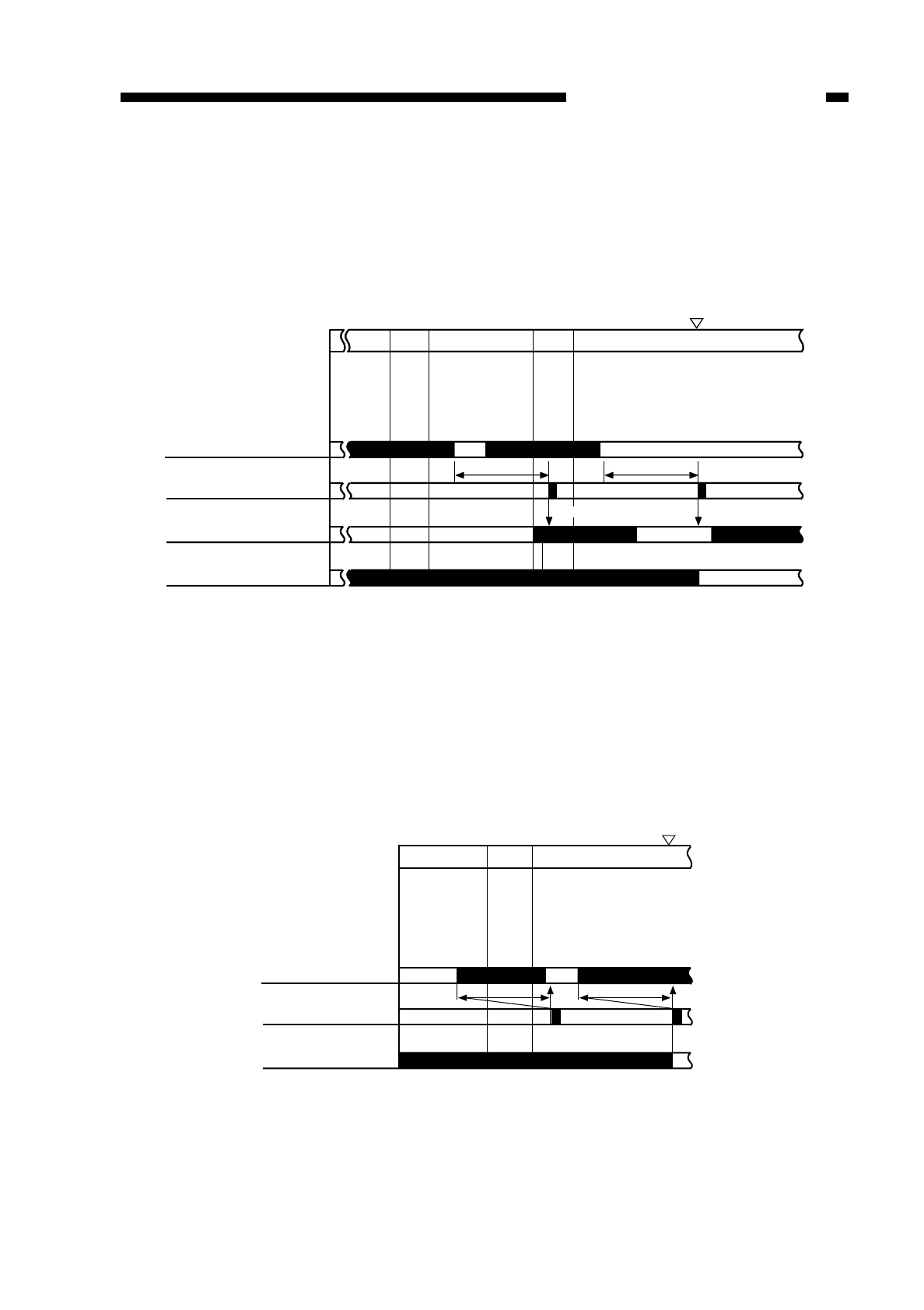
F. Delivery Delay Jam
Copy paper does not reach the delivery sensor (PS8) within a specific period of time
after it has moved past the separation sensor (PS7) because of feeding problems.
Figure 5-606 Delivery Delay Jam Sequence
G. Delivery Stationary Jam
Copy paper does not move past the delivery sensor within a specific period of time
after the delivery sensor (PS8) has gone on because of feeding problems.
Figure 5-607 Delivery Stationary Jam Sequence
COPYRIGHT
©
1997 CANON INC. CANON NP6218 REV. 0 MAY 1997 PRINTED IN JAPAN (IMPRIME AU JAPON)
CHAPTER 5 PICK-UP/FEEDING SYSTEM
5-15
Jam check
SCRV LSTRSCFW
Delivery sensor (PS8)
Normal Error
Main motor (M1)
Jam indicator
*1*1
Main motor (M1)
Jam check
SCRV SCRV LSTRSCFWSCFW
Separation sensor (PS7)
Delivery sensor (PS8)
Jam indicator
(flashing)
2.5 sec
Normal
2.5 sec
Error
Main motor (M1)
Jam check
SCRV SCRV LSTRSCFWSCFW
Separation sensor (PS7)
Delivery sensor (PS8)
Jam indicator
(flashing)
2.5 sec
Normal
2.5 sec
Error
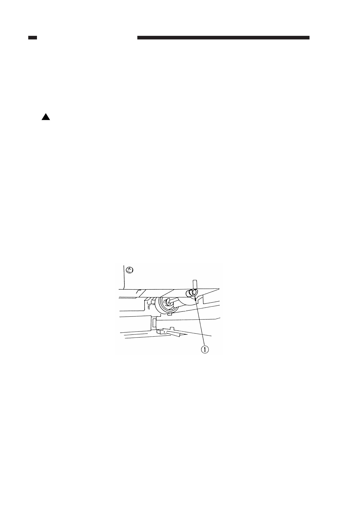
VII. DISASSEMBLY AND ASSEMBLY
This section explains mechanical characteristics and describes how to
disassemble/assemble the machine.
Be sure to observe the following whenever disassembling/assembling the machine:
1. Disconnect the power plug before starting the work.
2. Unless otherwise shown, assemble the parts by reversing the steps given to
disassemble them.
3. Identify each screw by type (length, diameter) and location.
4. A washer is used for one of the mounting screws on the rear cover to protect against
static electricity; be sure to use the washer when assembling the part.
5. A washer is used for some mounting screws (for grounding wire, varistor) to ensure
correct electrical continuity; be sure to use the washer when assembling the part.
6. As a rule, do not operate the machine while any of its parts are removed.
7. When sliding out the duplexing unit or the fixing assembly, be sure to turn off the front
door switch or the power switch.
A. Pick-Up Assembly
1. Detaching the Pick-Up Roller Unit
1) Pull out the cassette.
2) Remove the stop ring
q(plastic) from the front of the pick-up roller unit.
Figure 5-701
!
COPYRIGHT
©
1997 CANON INC. CANON NP6218 REV. 0 MAY 1997 PRINTED IN JAPAN (IMPRIME AU JAPON)
CHAPTER 5 PICK-UP/FEEDING SYSTEM
5-16
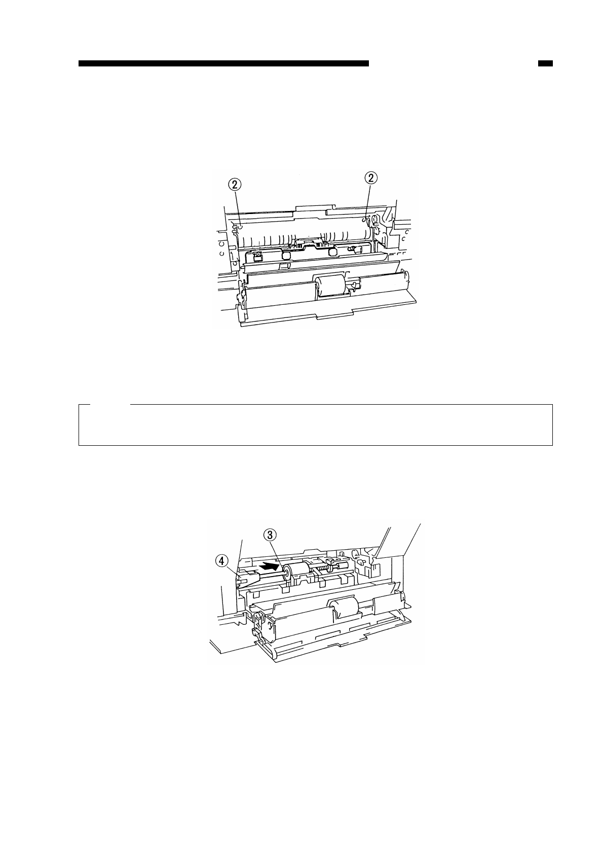
3) Open the lower right cover.
4) Remove the two screws w, and pull out the paper guide plate toward the front.
Figure 5-702
Note:
You will have sufficient access to the pick-up roller and the bushing at the rear in
this condition.
5) Push in the pick-up roller efrom the direction of step 4) toward the rear, and remove
the bushing rwhile lowering it to the lower left.
Figure 5-703
COPYRIGHT
©
1997 CANON INC. CANON NP6218 REV. 0 MAY 1997 PRINTED IN JAPAN (IMPRIME AU JAPON)
CHAPTER 5 PICK-UP/FEEDING SYSTEM
5-17
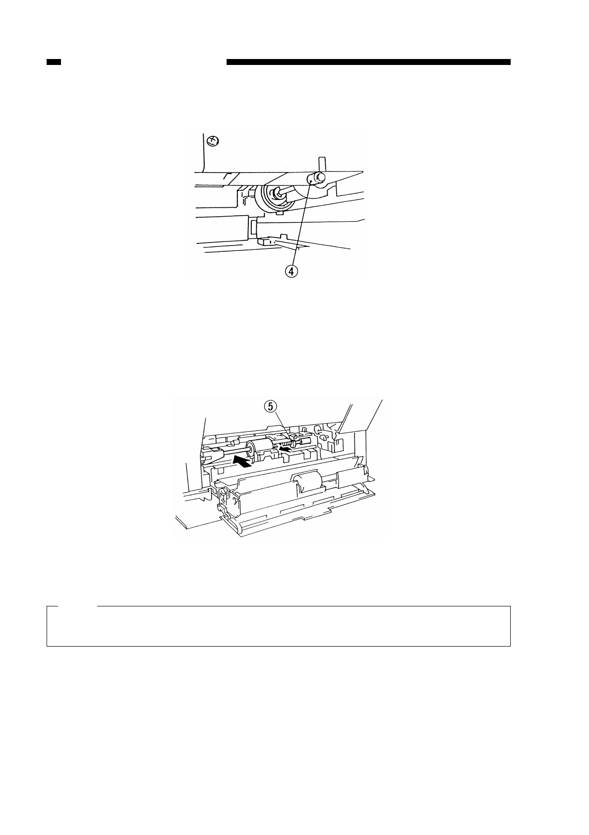
Figure 5-704
6) Push in the bushing tat the rear toward the front, and lower the spring pressure to
remove the pick-up unit toward the left of the copier.
Figure 5-705
Note:
When removing the pick-up roller Assembly, separate the right side black bushing
from the key.
COPYRIGHT
©
1997 CANON INC. CANON NP6218 REV. 0 MAY 1997 PRINTED IN JAPAN (IMPRIME AU JAPON)
CHAPTER 5 PICK-UP/FEEDING SYSTEM
5-18
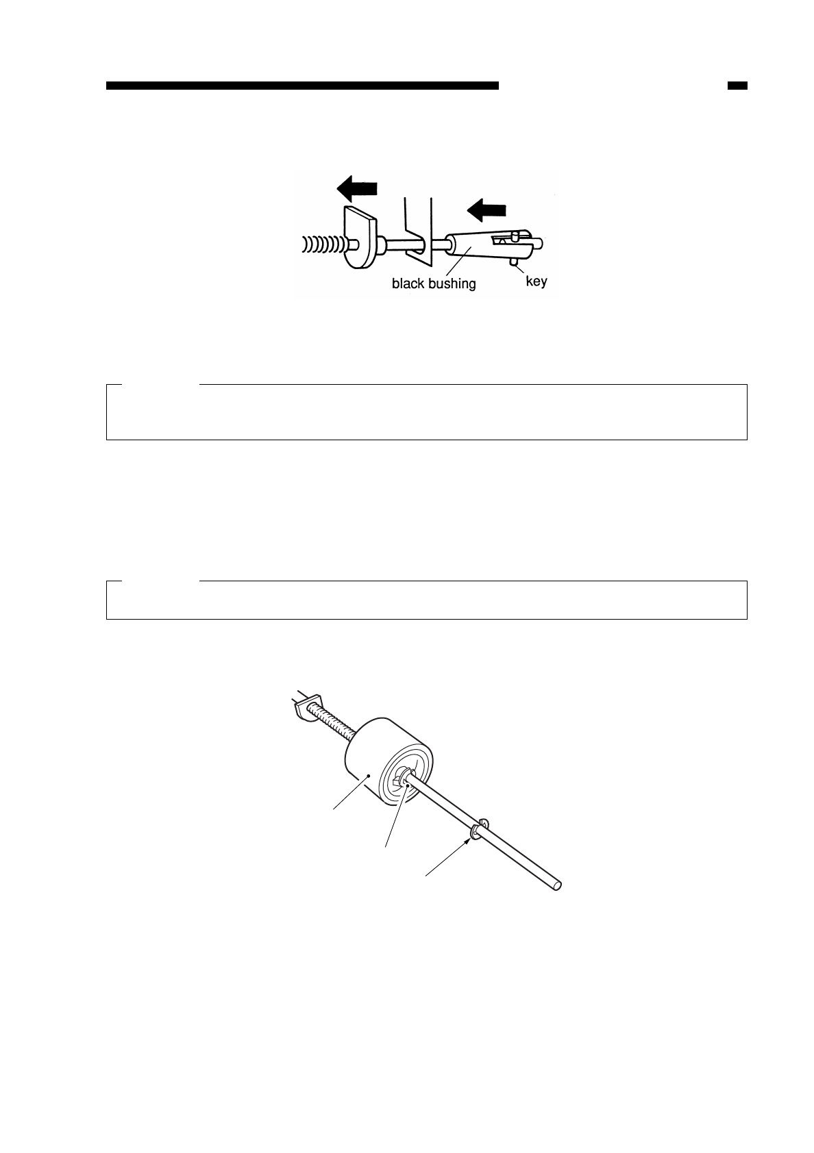
Figure 5-706
Caution:
Check that the paper registration sensor (PS 6) is properly seated after this
procedure is completed.
2. Detaching the Pick-Up Roller
1) Detach the pick-up roller unit. (See “1. Detaching the Pick-Up Roller Unit” on p. 5-
14.)
2) Remove the E-ring qand the E-ring w; then, pull out the pick-up roller etogether
with the collar.
Caution:
Take care not to drop the pin found toward the rear.
Figure 5-707
COPYRIGHT
©
1997 CANON INC. CANON NP6218 REV. 0 MAY 1997 PRINTED IN JAPAN (IMPRIME AU JAPON)
CHAPTER 5 PICK-UP/FEEDING SYSTEM
5-19
w
e
q
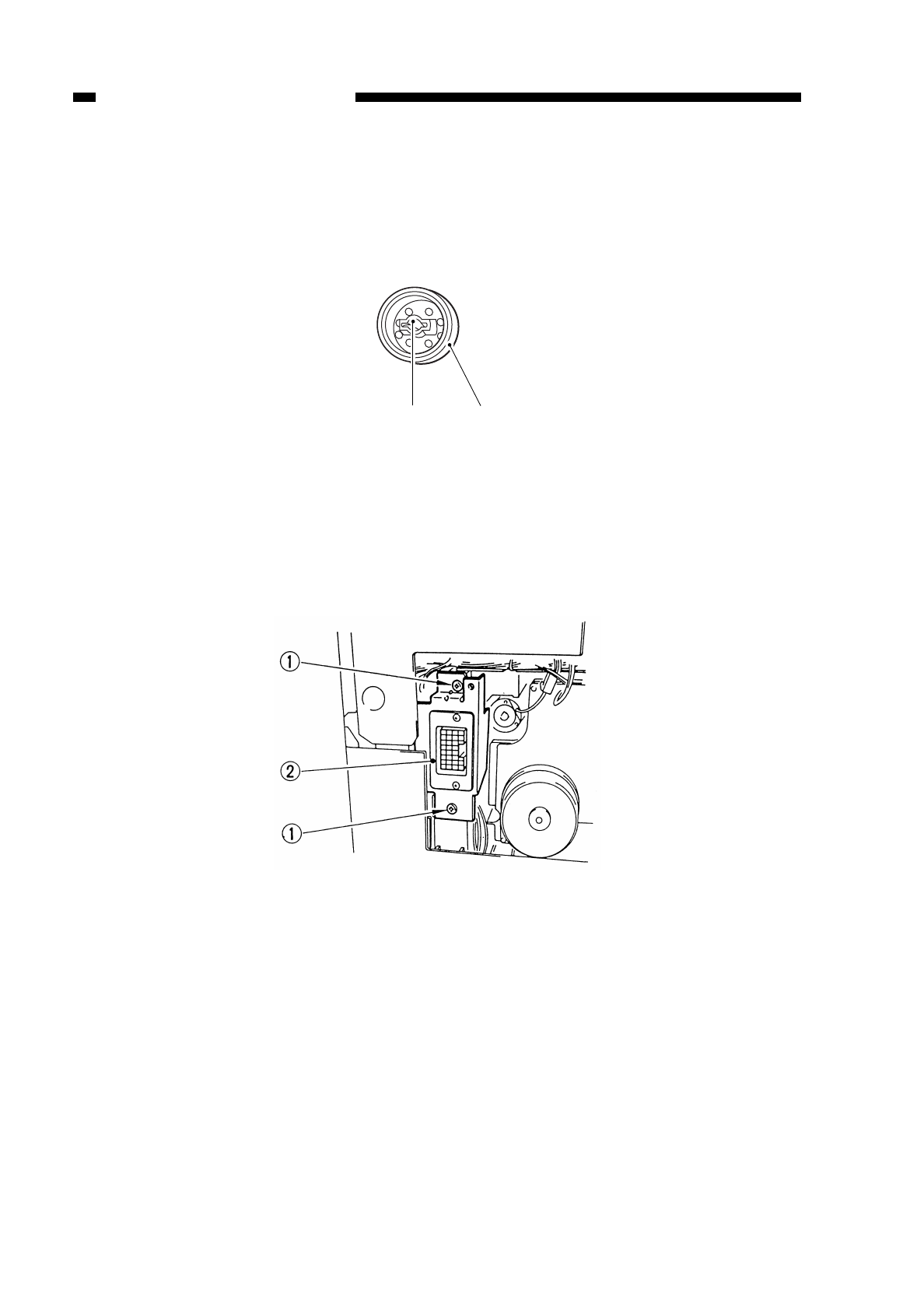
3. Points to Note When Attaching the Pick-Up Roller
When attaching the pick-up roller q, attach it so that the side wshown in Figure 5-
708 is toward the rear.
Figure 5-708
4. Detaching the Pick-Up Clutch
1) Detach the main motor unit. (See “1. Detaching the Main Motor Unit” on p. 7-11.)
2) Remove the two screws q, and detach the connector mount w.
Figure 5-709
COPYRIGHT
©
1997 CANON INC. CANON NP6218 REV. 0 MAY 1997 PRINTED IN JAPAN (IMPRIME AU JAPON)
CHAPTER 5 PICK-UP/FEEDING SYSTEM
5-20
q
w
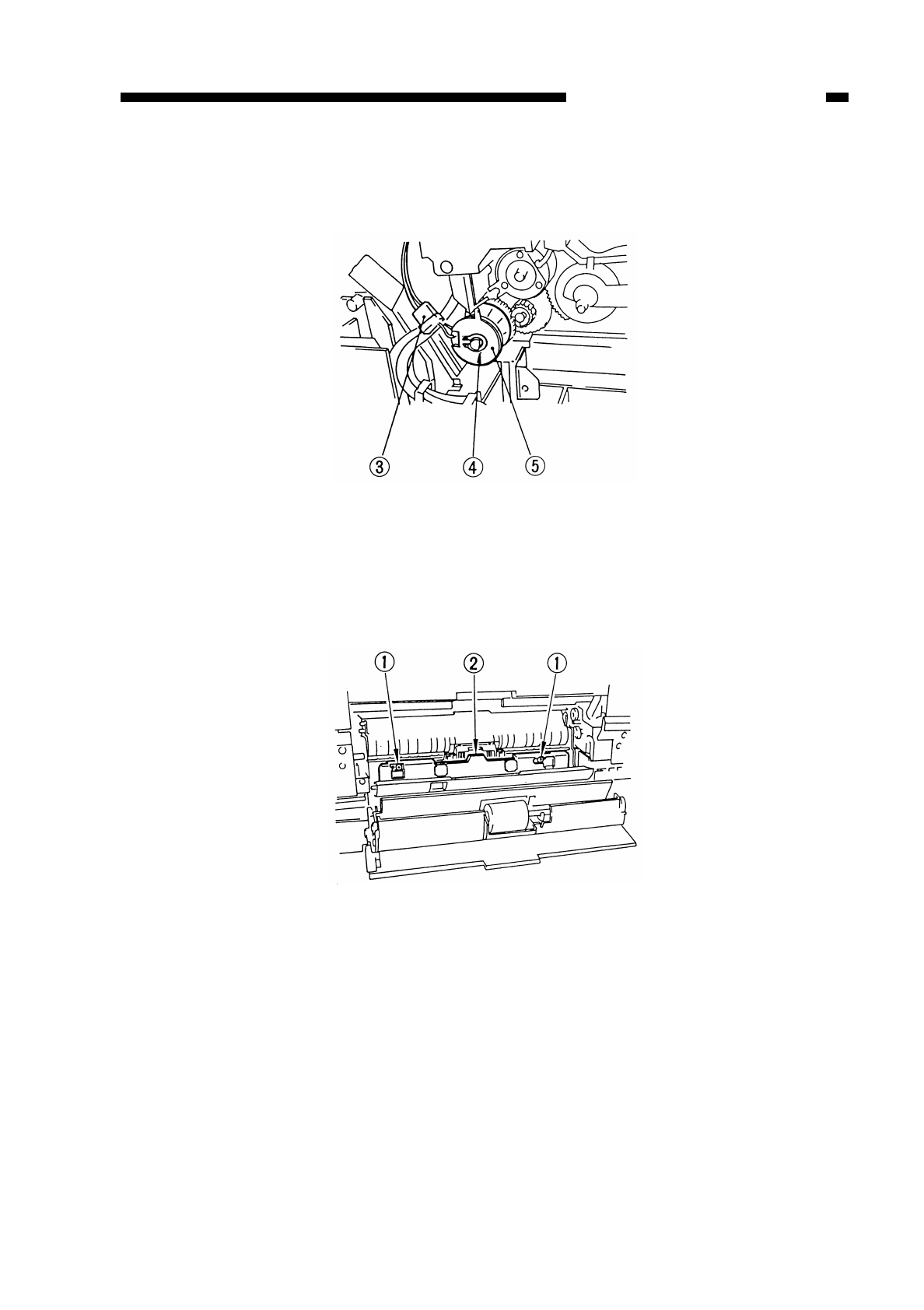
3) Disconnect the connector e, and remove the clip ring r; then, detach the pick-up
clutch t.
Figure 5-710
5. Detaching the Separation Pad
1) Open the right door.
2) Remove the two screws q, and detach the separation cover w.
Figure 5-711
COPYRIGHT
©
1997 CANON INC. CANON NP6218 REV. 0 MAY 1997 PRINTED IN JAPAN (IMPRIME AU JAPON)
CHAPTER 5 PICK-UP/FEEDING SYSTEM
5-21
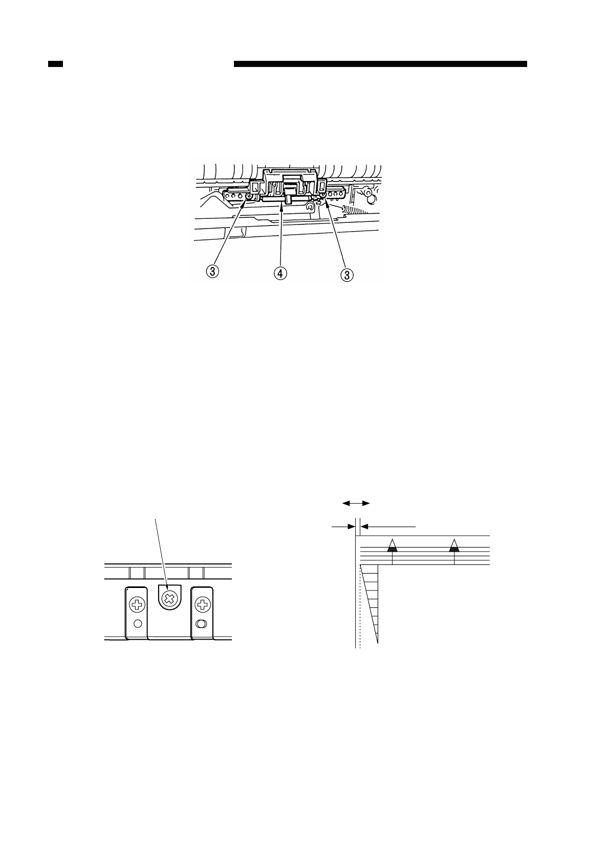
3) Remove the two screws e, and detach the separation pad unit r.
Figure 5-712
6. Adjusting the Left/Right Registration
Make adjustments so that the position of the image is as shown in Figure 5-714 when
the Test Sheet is copied in Direct.
a. Pick-Up from the Cassette
Turn the screw qshown in Figure 5-713 to adjust the position of the cassette hook
plate.
standard: 0 ±1.5 mm
clockwise turn: moves the paper in the direction of – shown in Figure 5-714
counterclockwise turn: moves the paper in the direction of + shown in Figure 5-714
Figure 5-713 Figure 5-714
COPYRIGHT
©
1997 CANON INC. CANON NP6218 REV. 0 MAY 1997 PRINTED IN JAPAN (IMPRIME AU JAPON)
CHAPTER 5 PICK-UP/FEEDING SYSTEM
5-22
(-) (+)
0±1.5mm
0
2
4
6
8
10
q
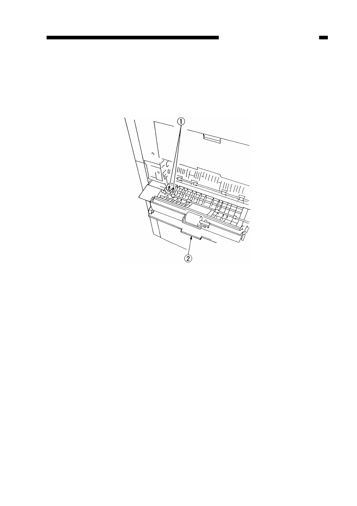
B. Multifeeder Assembly
1. Detaching the Multifeeder Assembly
1) Open the right door.
2) Remove the two screws q, and shift the multifeeder assembly wtoward the front to
detach.
Figure 5-715
COPYRIGHT
©
1997 CANON INC. CANON NP6218 REV. 0 MAY 1997 PRINTED IN JAPAN (IMPRIME AU JAPON)
CHAPTER 5 PICK-UP/FEEDING SYSTEM
5-23
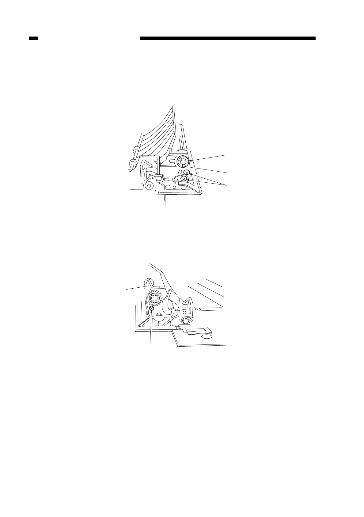
2. Detaching the Multifeeder Pick-Up Roller Unit
1) Open the right door.
2) Remove the E-ring q, and pull out the bushing w.
3) Remove the two screws e.
Figure 5-716
4) Remove the screw r, and detach the roller cover t.
Figure 5-717
COPYRIGHT
©
1997 CANON INC. CANON NP6218 REV. 0 MAY 1997 PRINTED IN JAPAN (IMPRIME AU JAPON)
CHAPTER 5 PICK-UP/FEEDING SYSTEM
5-24
q
w
e
r
t
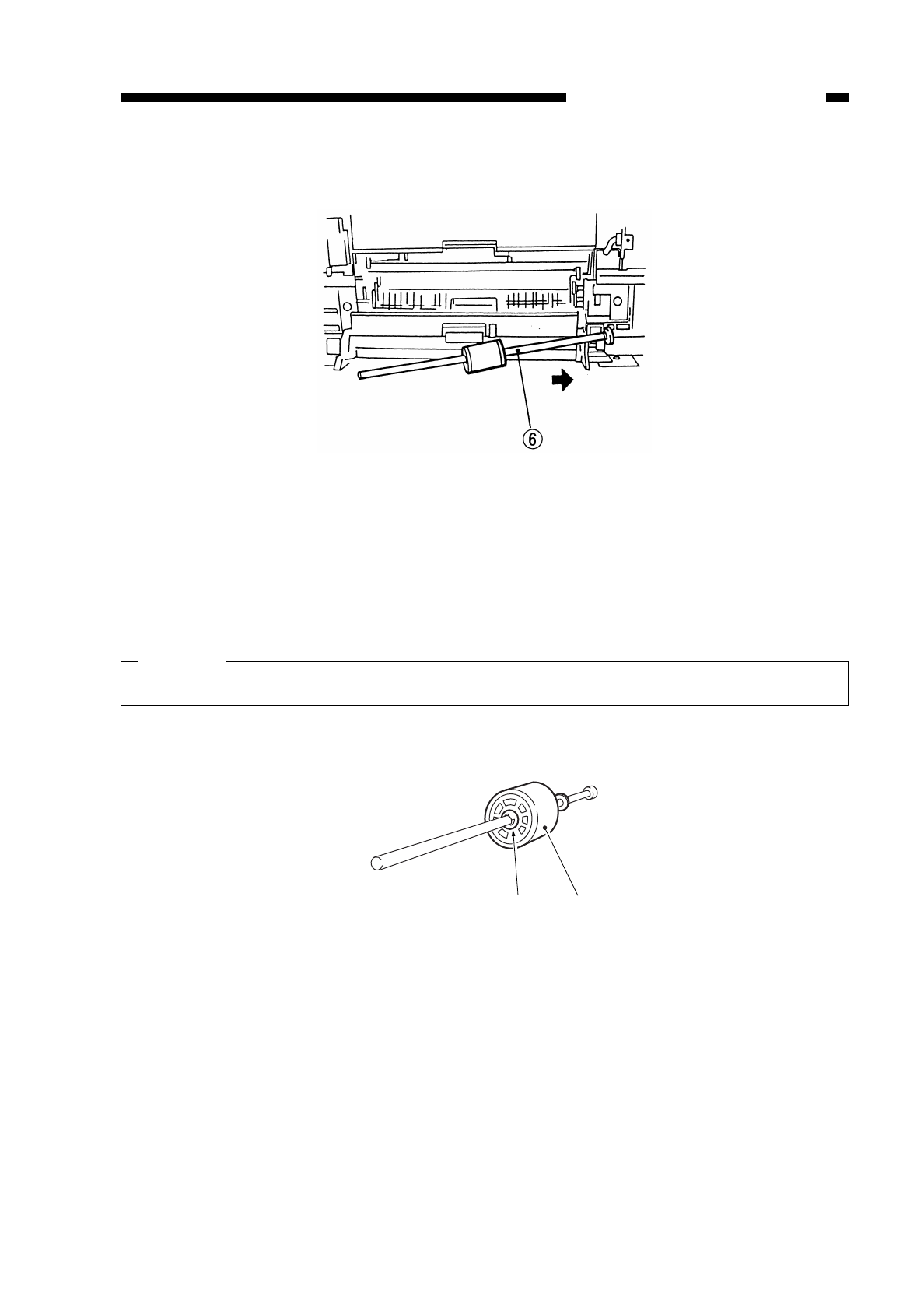
5) Shift the multifeeder pick-up roller unit ytoward the rear to detach.
Figure 5-718
3. Detaching the Multifeeder Pick-Up Roller
1) Detach the multifeeder pick-up roller unit. (See “2. Detaching the Multifeeder Pick-Up
Roller Unit on p. 5-22.”)
2) Remove the stop ring q(plastic), and pull out the pick-up roller wtogether with the
collar.
Caution:
Take care not to drop the pin found at the rear.
Figure 5-719
COPYRIGHT
©
1997 CANON INC. CANON NP6218 REV. 0 MAY 1997 PRINTED IN JAPAN (IMPRIME AU JAPON)
CHAPTER 5 PICK-UP/FEEDING SYSTEM
5-25
qw
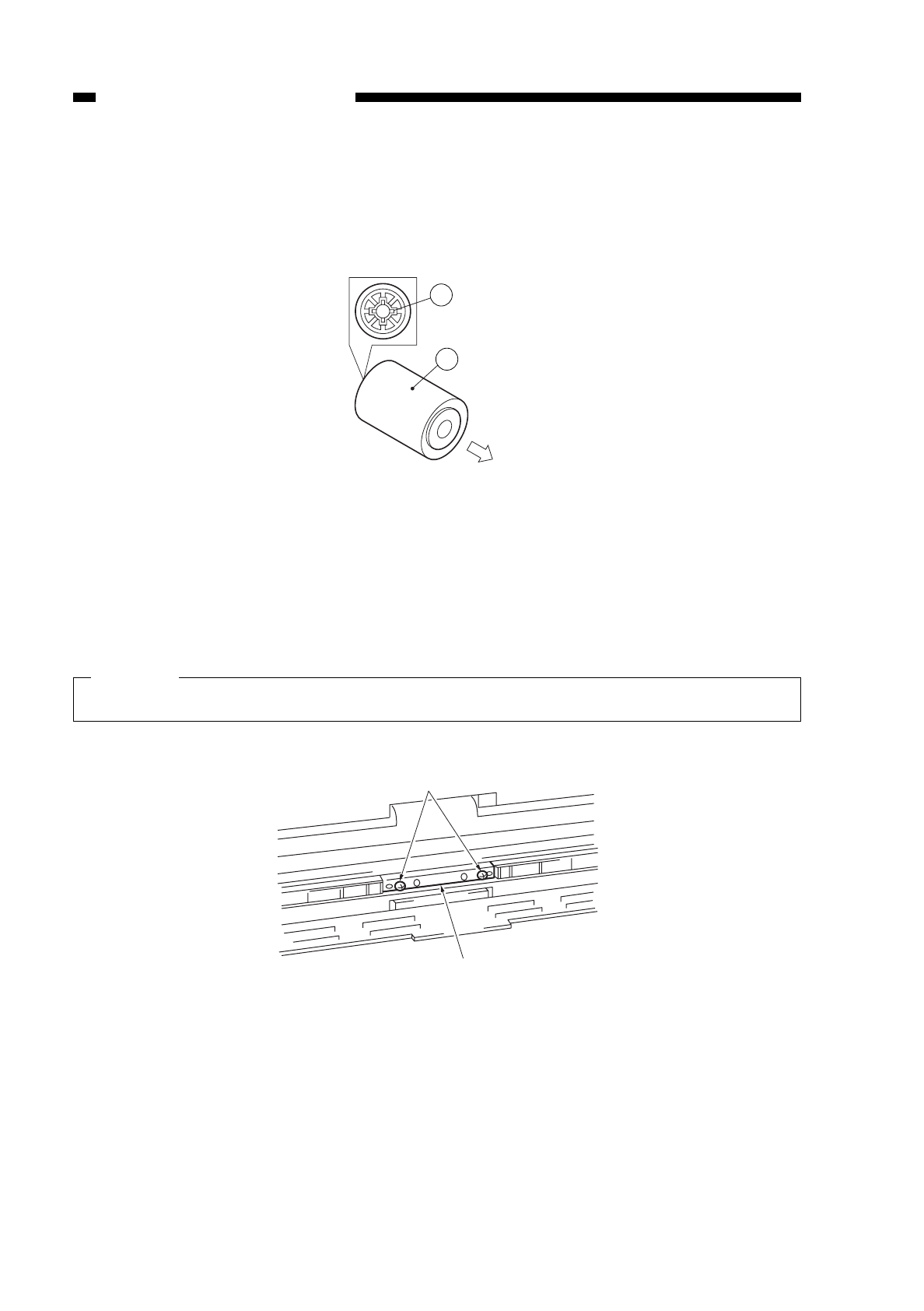
4. Points to Keep Note When Attaching the Multifeeder Pick-Up Roller
When attaching the multifeeder pick-up roller q, make sure that the side with a cross
won the collar is toward the rear.
Figure 5-720
5. Detaching the Separation Pad
1) Open the upper right door.
2) Remove the two screws q, and detach the separation pad w.
Caution:
At this time, take care not to lose the spring on the separation pad assembly.
Figure 5-721
COPYRIGHT
©
1997 CANON INC. CANON NP6218 REV. 0 MAY 1997 PRINTED IN JAPAN (IMPRIME AU JAPON)
CHAPTER 5 PICK-UP/FEEDING SYSTEM
5-26
(front of copier)
2
1
w
q
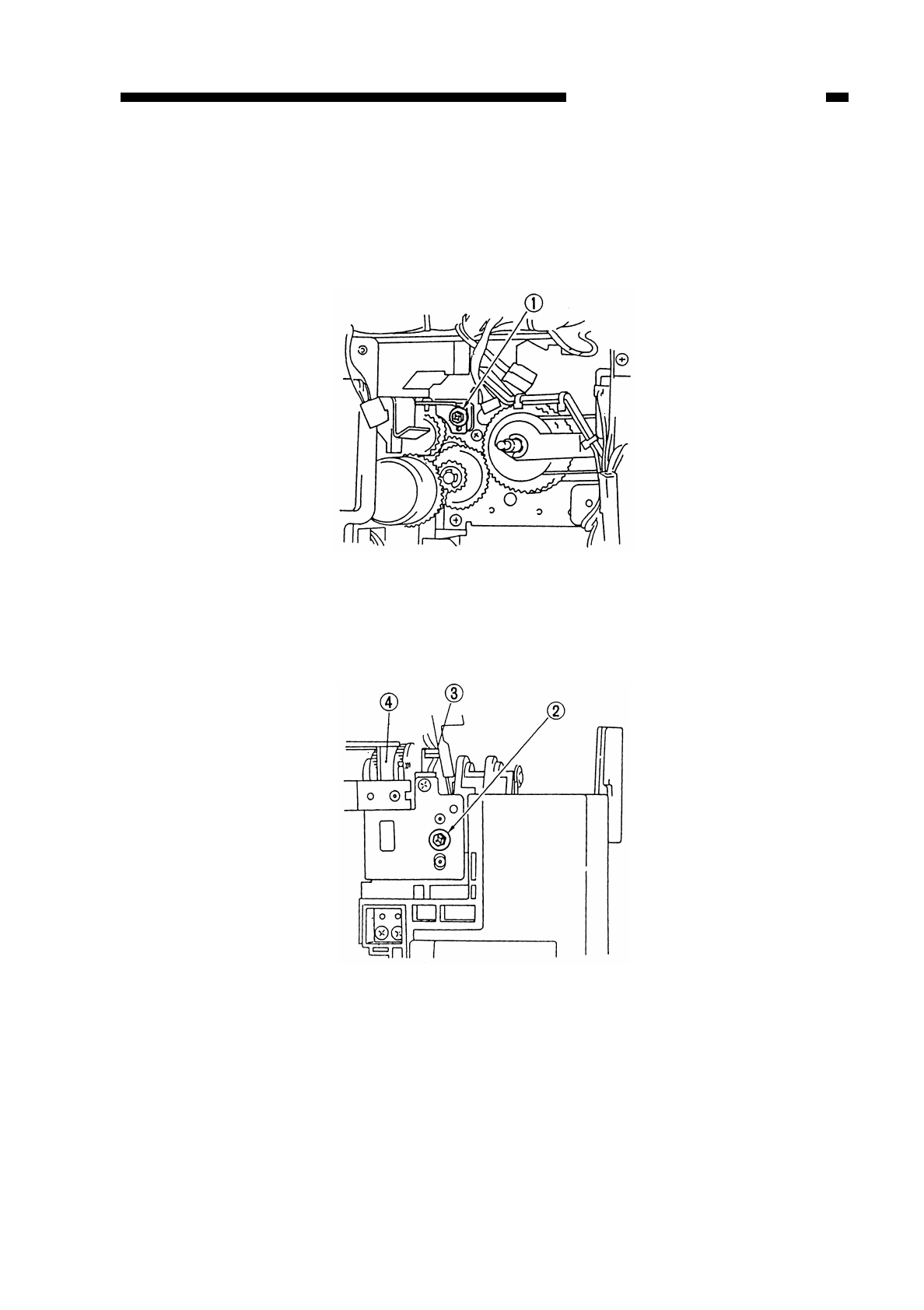
6. Detaching the Multifeeder Drive Unit
1) Detach the multifeeder assembly. (See “1. Detaching the Multifeeder Assembly on p.
5-21.”)
2) Detach the connector mount.
3) Remove the screw q.
Figure 5-722
4) Remove the screw w, and disconnect the connector e; then, detach the multifeeder
drive unit r.
Figure 5-723
COPYRIGHT
©
1997 CANON INC. CANON NP6218 REV. 0 MAY 1997 PRINTED IN JAPAN (IMPRIME AU JAPON)
CHAPTER 5 PICK-UP/FEEDING SYSTEM
5-27
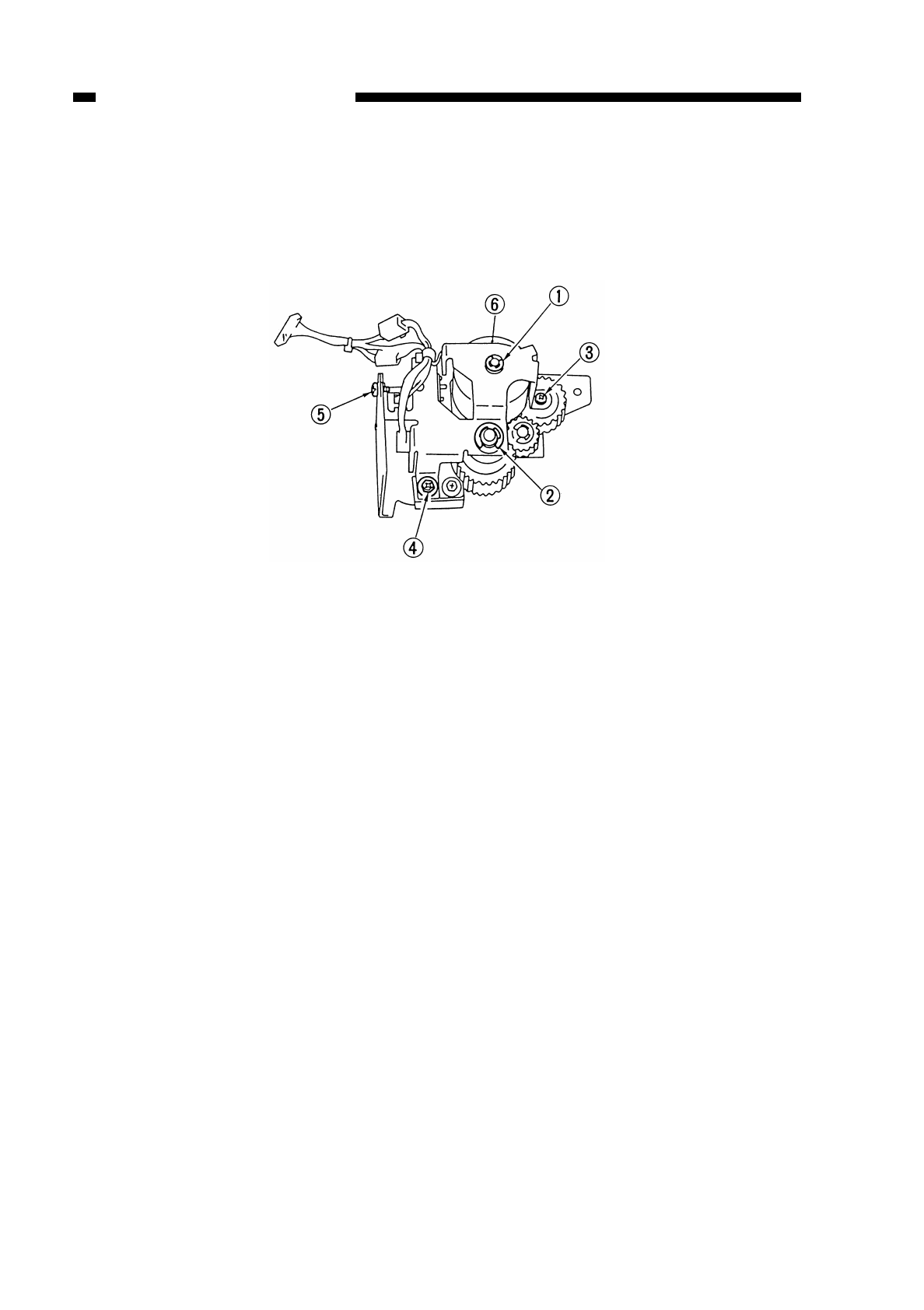
7. Detaching the Multifeeder Clutch
1) Detach the multifeeder drive unit. (See “6. Multifeeder drive Unit on p. 5-25.”)
2) Remove the E-rings qwand screws ert; then, detach the support mount.
3) Detach the multifeeder pick-up clutch y.
Figure 5-724
COPYRIGHT
©
1997 CANON INC. CANON NP6218 REV. 0 MAY 1997 PRINTED IN JAPAN (IMPRIME AU JAPON)
CHAPTER 5 PICK-UP/FEEDING SYSTEM
5-28
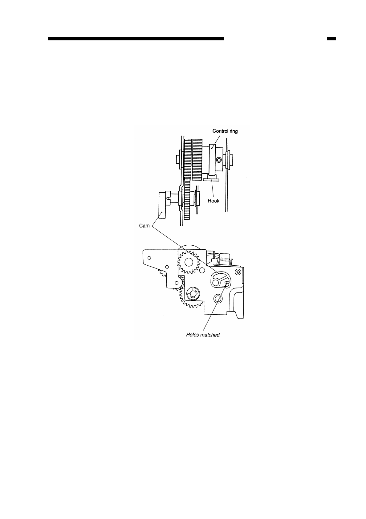
8. Positioning the Multifeeder Assembly (paper guide plate cam)
Temporarily fix the screw equipped with a hex nut on the spring clutch assembly, and
rotate the control ring. Make adjustments so that the hole in the cam and the hole in the
multifeeder drive unit match as shown in Figure 5-725 when the claw is engaged with the
solenoid plate; then, fix in position.
Figure 5-725
COPYRIGHT
©
1997 CANON INC. CANON NP6218 REV. 0 MAY 1997 PRINTED IN JAPAN (IMPRIME AU JAPON)
CHAPTER 5 PICK-UP/FEEDING SYSTEM
5-29
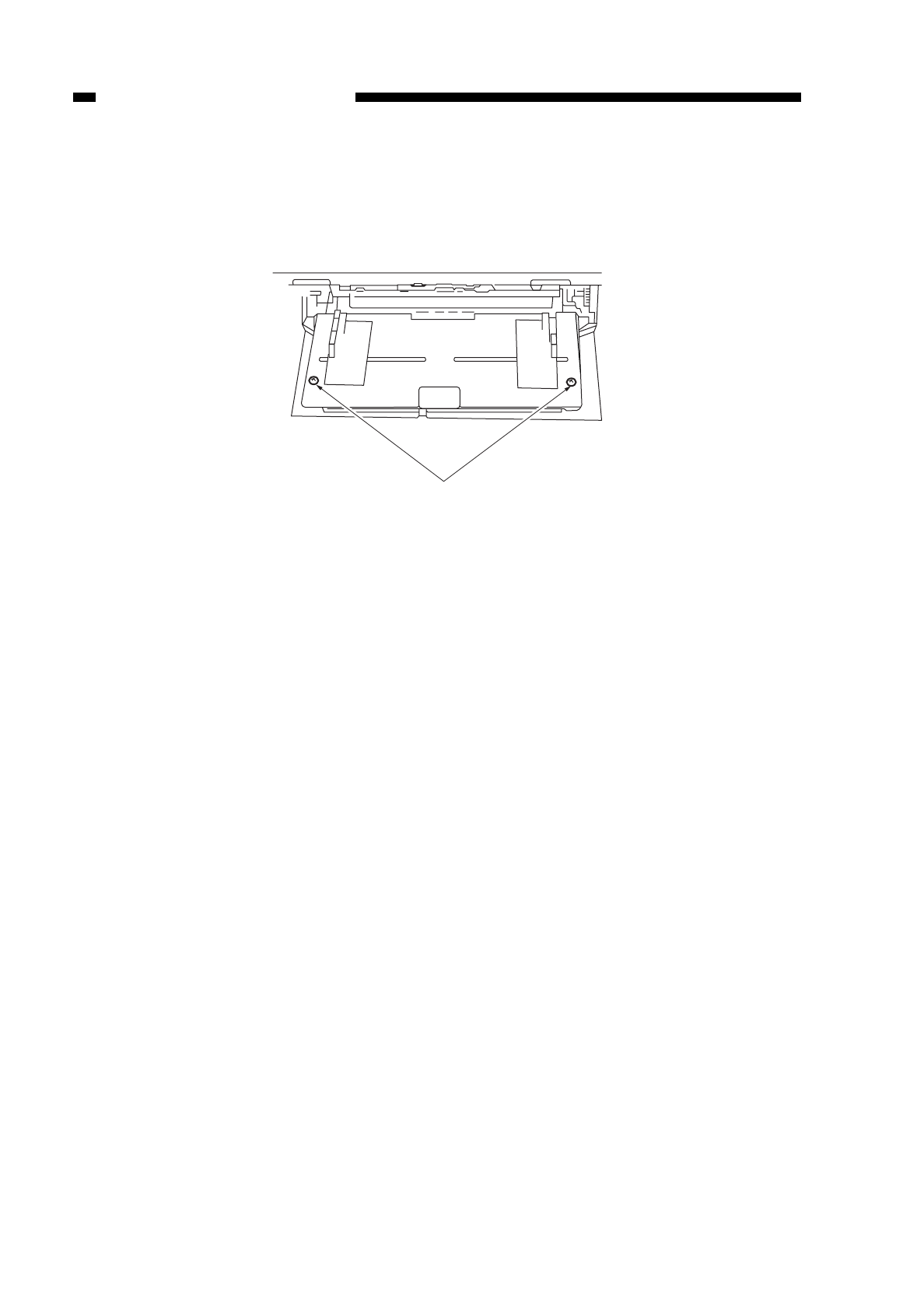
9. Adjusting the Left/Right Registration
If the right/left registration is not correct when copies are made using the multifeeder,
loosen the screw q, and adjust the position of the tray.
Figure 5-726
10.Points to Note When Attaching the Multifeeder Assembly Rack Plate
Attach the rack plate of the multifeeder to the pulley while both its right and left are
fully open.
COPYRIGHT
©
1997 CANON INC. CANON NP6218 REV. 0 MAY 1997 PRINTED IN JAPAN (IMPRIME AU JAPON)
CHAPTER 5 PICK-UP/FEEDING SYSTEM
5-30
q
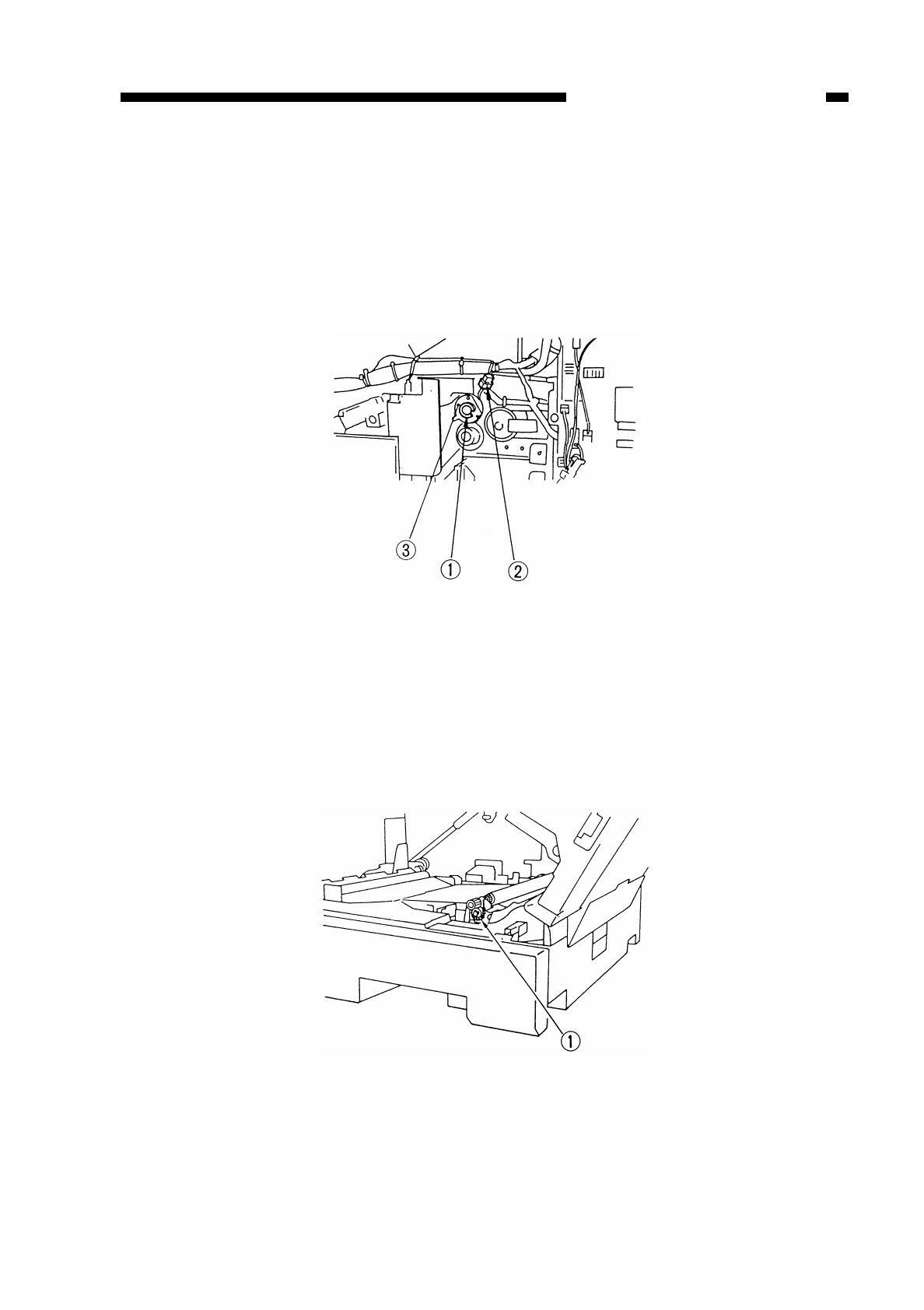
C. Registration Roller Assembly
1. Detaching the Registration Clutch
1) Detach the connector cover or the lattice connector
2) Remove the clip ring q, and disconnect the connector w; then, detach the
registration clutch e.
Figure 5-727
2. Detaching the Upper Registration Roller
1) Detach the registration clutch. (See “1. Detaching the Registration Clutch on p. 5-
29.”)
2) Remove the spring q(front) and spring w(rear).
Figure 5-728
COPYRIGHT
©
1997 CANON INC. CANON NP6218 REV. 0 MAY 1997 PRINTED IN JAPAN (IMPRIME AU JAPON)
CHAPTER 5 PICK-UP/FEEDING SYSTEM
5-31
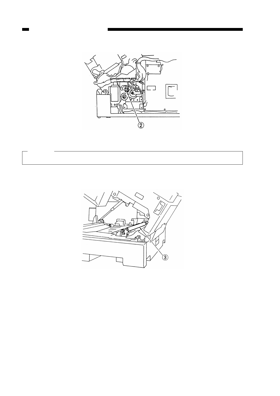
Figure 5-729
Caution:
Take care not to misplace the springs (front, rear).
3) Lift the upper registration roller eto detach.
Figure 5-730
COPYRIGHT
©
1997 CANON INC. CANON NP6218 REV. 0 MAY 1997 PRINTED IN JAPAN (IMPRIME AU JAPON)
CHAPTER 5 PICK-UP/FEEDING SYSTEM
5-32
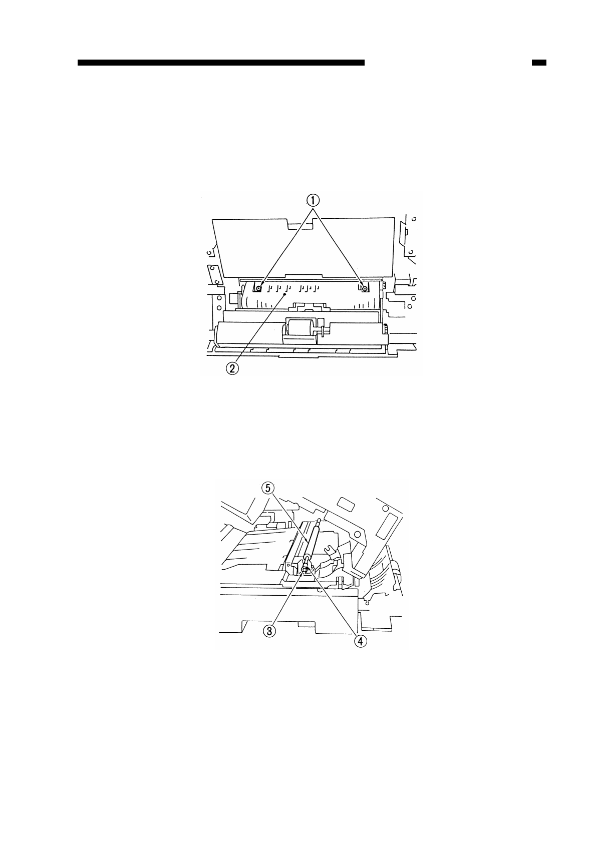
3. Detaching the Lower Registration Roller
1) Detach the upper registration roller. (See “2. Detaching the Upper Registration Roller
on p. 5-29.”)
2) Open the lower right door, and remove the two screws qto shift the pick-up guide
wtoward the right side of the copier.
Figure 5-731
3) Remove the E-ring e(front), and shift the bushing r.
4) Detach the registration roller t.
Figure 5-732
COPYRIGHT
©
1997 CANON INC. CANON NP6218 REV. 0 MAY 1997 PRINTED IN JAPAN (IMPRIME AU JAPON)
CHAPTER 5 PICK-UP/FEEDING SYSTEM
5-33
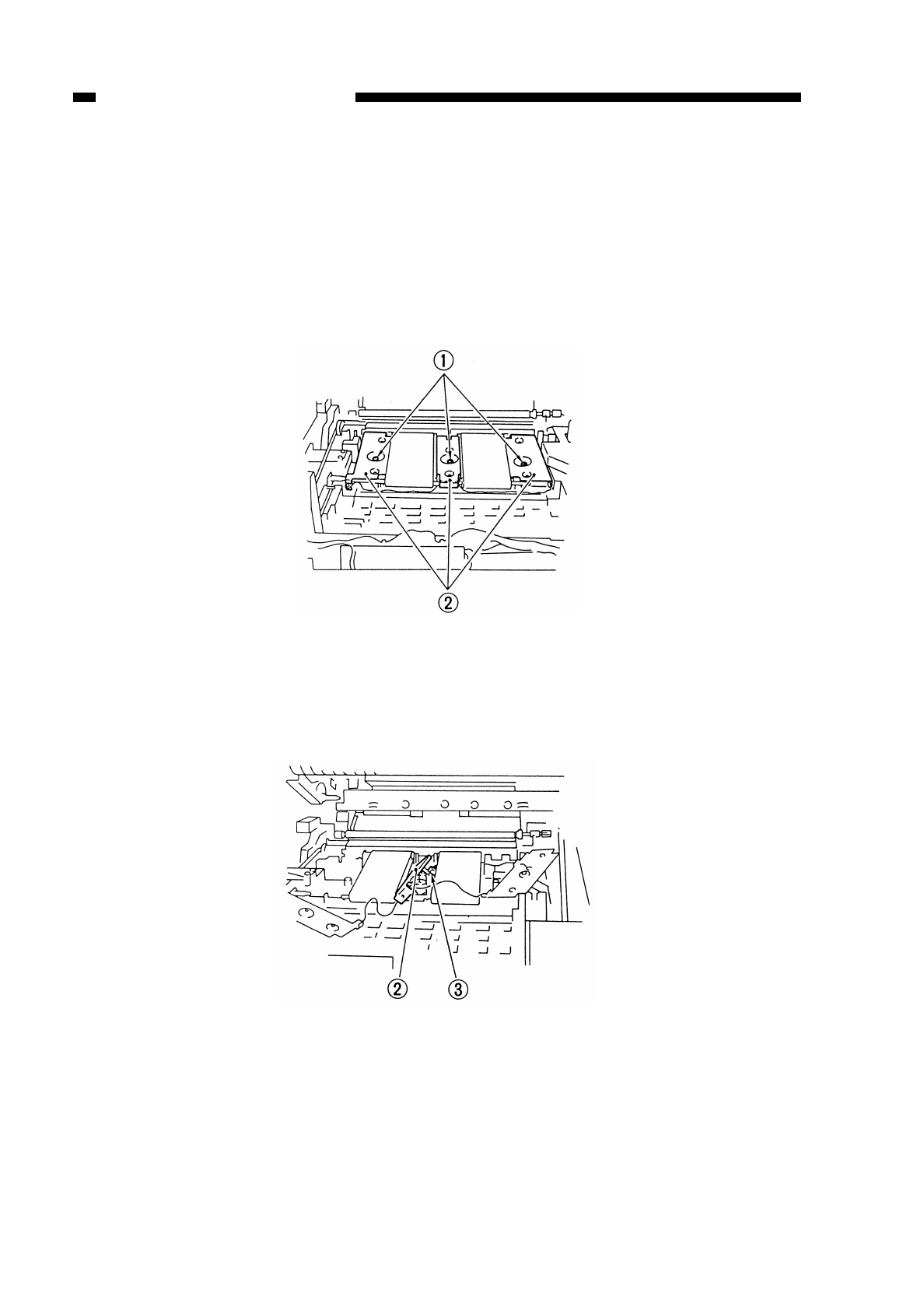
D. Feeding Assembly
Be sure to detach the cartridge before detaching the feeding assembly.
1. Detaching the Feeding Belt
1) Detach the lower fixing unit. (See “8. Detaching the Lower Fixing Unit” on p. 6-23.)
2) Remove the three screws q, and shift the feeding retention plate w.
Figure 5-733
3) Disconnect the connector e, and shift the feeding retention plate w.
Figure 5-734
COPYRIGHT
©
1997 CANON INC. CANON NP6218 REV. 0 MAY 1997 PRINTED IN JAPAN (IMPRIME AU JAPON)
CHAPTER 5 PICK-UP/FEEDING SYSTEM
5-34
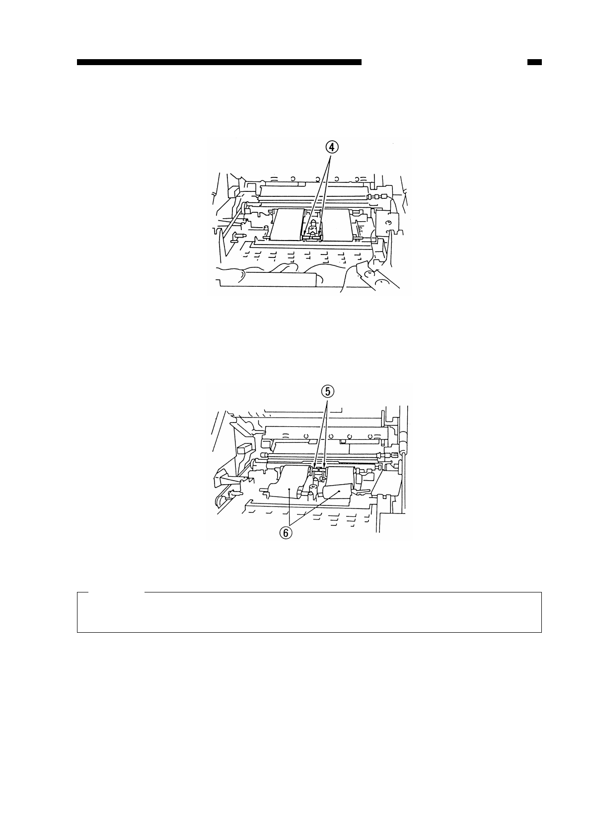
4) Detach the feeding spacer rby pulling it toward the fixing assembly.
Figure 5-735
5) Detach the static eliminator.
6) Detach the feeding spacer tfrom the hook (arrow).
Figure 5-736
Caution:
Take care not to touch the transfer roller. Do not damage the area where the
feeding spacers are in contact.
COPYRIGHT
©
1997 CANON INC. CANON NP6218 REV. 0 MAY 1997 PRINTED IN JAPAN (IMPRIME AU JAPON)
CHAPTER 5 PICK-UP/FEEDING SYSTEM
5-35
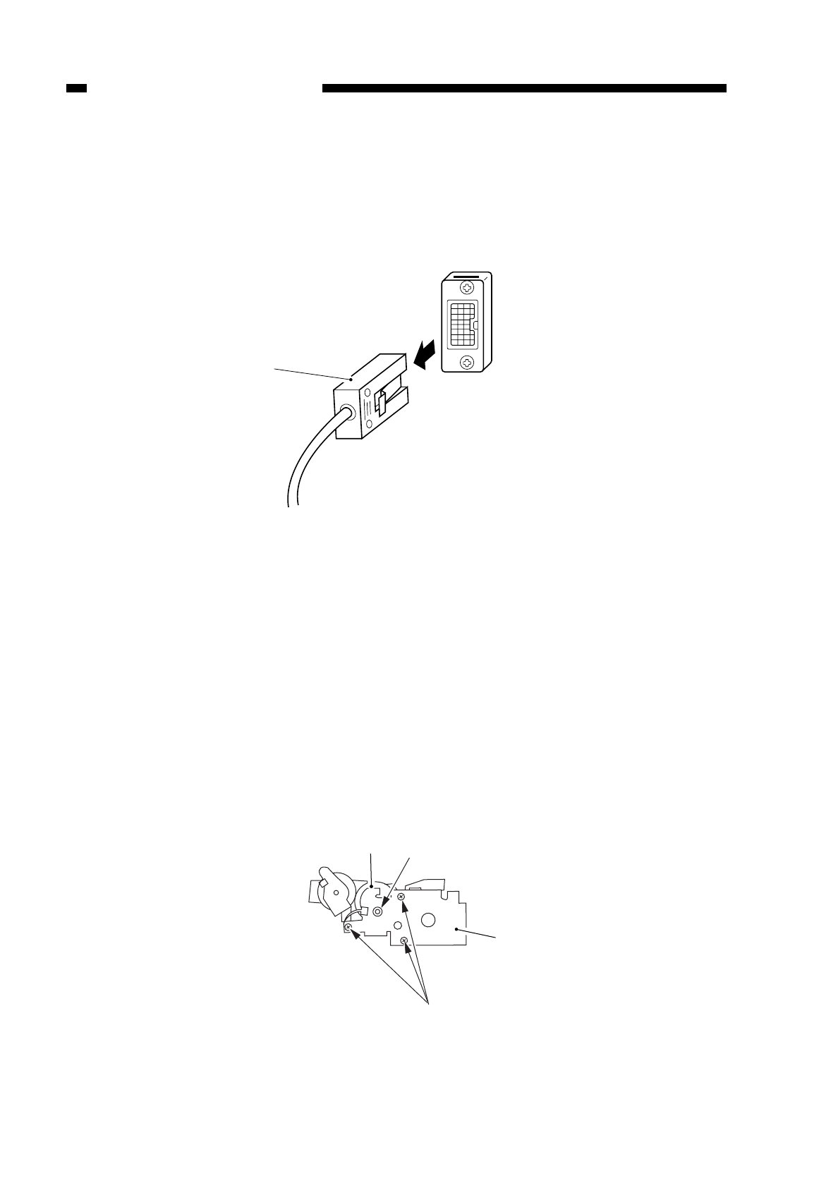
E. Cassette Feeding Module
1. Detaching the Copier from the Cassette Feeding Module
1) Disconnect the copier’s power plug.
2) Disconnect the connector qof the cassette feeding module.
Figure 5-737
3) Hold the copier’s grips, and detach the copier from the cassette feeding module.
2. Detaching/Attaching the Pick-Up Roller
See p. 5-14 “1. Detaching the Pick-Up Roller Unit”, p. 5-17 “2. Detaching the Pick-Up
Roller” and p. 5-18 “3. Points to Note When Attaching the Pick-Up Roller.”
3. Detaching the Pick-Up Clutch
1) Detach the pick-up drive unit. (See p. 7-14 “1. Detaching the Pick-Up Drive Unit.”)
2) Detach the cassette motor. (See p. 7-15 “2. Detaching the Cassette Motor.”)
3) Remove the three screws q, and detach the bushing wand side plate e; then,
detach the pick-up clutch r.
Figure 5-738
COPYRIGHT
©
1997 CANON INC. CANON NP6218 REV. 0 MAY 1997 PRINTED IN JAPAN (IMPRIME AU JAPON)
CHAPTER 5 PICK-UP/FEEDING SYSTEM
5-36
r
q
w
e
q

COPYRIGHT
©
1997 CANON INC. CANON NP6218 REV. 0 MAY 1997 PRINTED IN JAPAN (IMPRIME AU JAPON)
CHAPTER 6
FIXING SYSTEM
I. BASIC OPERATIONS.........................6-1
A. Outline ...........................................6-1
B. Controlling the Fixing Heater
Temperature ..................................6-3
C. Controlling the Supply Power for
the Fixing Heater...........................6-5
D. Detecting Overheating at the End
of the Fixing Heater.......................6-6
E. Protection Mechanism...................6-6
F. Correcting Displacement of the
Fixing Film .....................................6-7
II. DISASSEMBLY AND ASSEMBLY ......6-11
A. Fixing Assembly ............................6-11
B. Delivery Assembly.........................6-27
This chapter explains the principles used to fuse toner images to transfer medium in view of the
functions of electrical and mechanical units and in relation to their timing of operation. It also shows
how these units may be disassembled/assembled and adjusted.
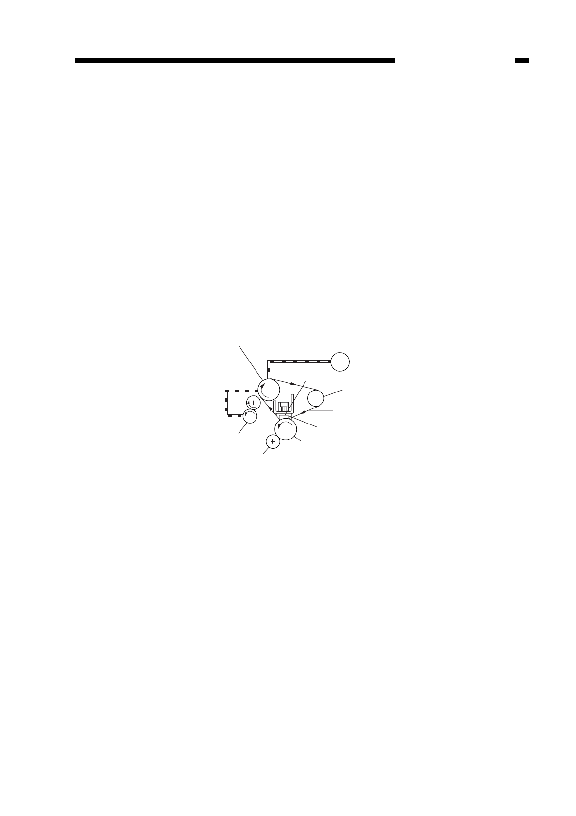
COPYRIGHT
©
1997 CANON INC. CANON NP6218 REV. 0 MAY 1997 PRINTED IN JAPAN (IMPRIME AU JAPON)
CHAPTER 6 FIXING SYSTEM
6-1
I. BASIC OPERATIONS
A. Outline
The drive roller of the fixing assembly is driven by the main motor (M1).
When the drive roller rotates, the fixing film rotates and, in conjunction, the pressure
roller rotates.
Part of the inside of the fixing film is heated by the fixing heater.
The temperature of the fixing heater is monitored by a thermistor (TH1), and the
result is sent to the microprocessor in the DC controller circuit in the form of the fixing
heater temperature detection signal (TH1).
Based on the result (TH1 signal), the microprocessor on the DC controller varies the
fixing heater drive signal (HTRD) to control the temperature of the fixing heater.
Further, a thermistor (TH2) is also provided on the end (rear) of the fixing heater to
monitor overheating.
Figure 6-101
Drive roller
Delivery roller
Fixing cleaning roller
M1
Pressure roller
Fixing heater
Fixing film
Tension roller
Main motor
Thermistor
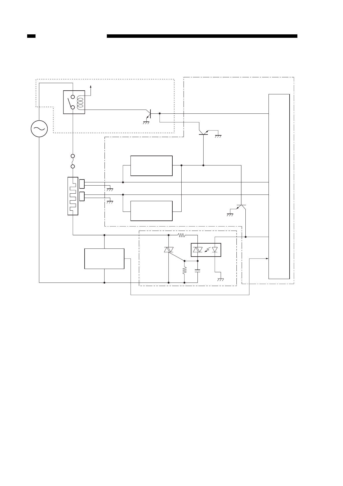
Figure 6-102
PWSW*
Relay
(RL101)
+5V Composite power supply PCB
Thermal fuse
FU1
Fixing heater
end temperature
detection
TH2 TH2
TH1
TH1
Fixing heater
H1
Fixing heater
temperature
etection
Heater ON
detection PCB
Fixing heater
overheating
detection circuit
Fixing heater
end overheating
detection circuit
HTNG
Micro-
processor
HTRD
HTON*
DC controller PCB
Fixing heater driver PCB
COPYRIGHT
©
1997 CANON INC. CANON NP6218 REV. 0 MAY 1997 PRINTED IN JAPAN (IMPRIME AU JAPON)
CHAPTER 6 FIXING SYSTEM
6-2

B. Controlling the Fixing Heater Temperature
The fixing heater remains off while the copier is in standby state. To prevent fixing
faults caused by low temperature, its temperature is controlled in any of the following
three modes depending on the temperature at the time copying is started (as measured
by the main thermistor TH1) and the number of copies to be made in continuous mode:
a. If the temperature at the time copying is started is 140°C or more, it is controlled so
that it remains 180°C at all times.
• 1st to 100th copy
→180°C
b. If the temperature at the time copying is started is 120°C or more and less than
140°C, it is controlled so that it remains between 200° and 180°C depending on the
number of copies to be made.
• 1st copy →200°C
• 2nd to 9th copy →195°C
• 10th to 20th copy →190°C
• 21st to 25th copy →185°C
• 26th to 100th copy →180°C
c. If the temperature at the time copying is started is less than 120°C or less, the
temperature is controlled to 225°-180°C, 215°-180°C, or 200°-180°C selected by
service mode. (See the Service Handbook.)
■Control 1
• 1st to 4th copy →225°C
• 5th copy →220°C
• 6th copy →215°C
• 7th copy →210°C
• 8th copy →205°C
• 9th to 20th copy →200°C
• 21st to 25th copy →195°C
• 26th to 40th copy →190°C
• 41st to 45th copy →185°C
• 46th to 100th copy →180°C
■Control 2 (default)
• 1st to 4th copy →215°C
• 5th copy →210°C
• 6th copy →205°C
• 7th to 20th copy →200°C
• 21st to 25th copy →195°C
• 26th to 40th copy →190°C
• 41st to 45th copy →185°C
• 46th to 100th copy →180°C
■Control 3
• 1st to 20th copy →200°C
• 21st to 25th copy →195°C
• 26th to 40th copy →190°C
• 41st to 45th copy →185°C
• 46th to 100th copy →180°C
COPYRIGHT
©
1997 CANON INC. CANON NP6218 REV. 0 MAY 1997 PRINTED IN JAPAN (IMPRIME AU JAPON)
CHAPTER 6 FIXING SYSTEM
6-3
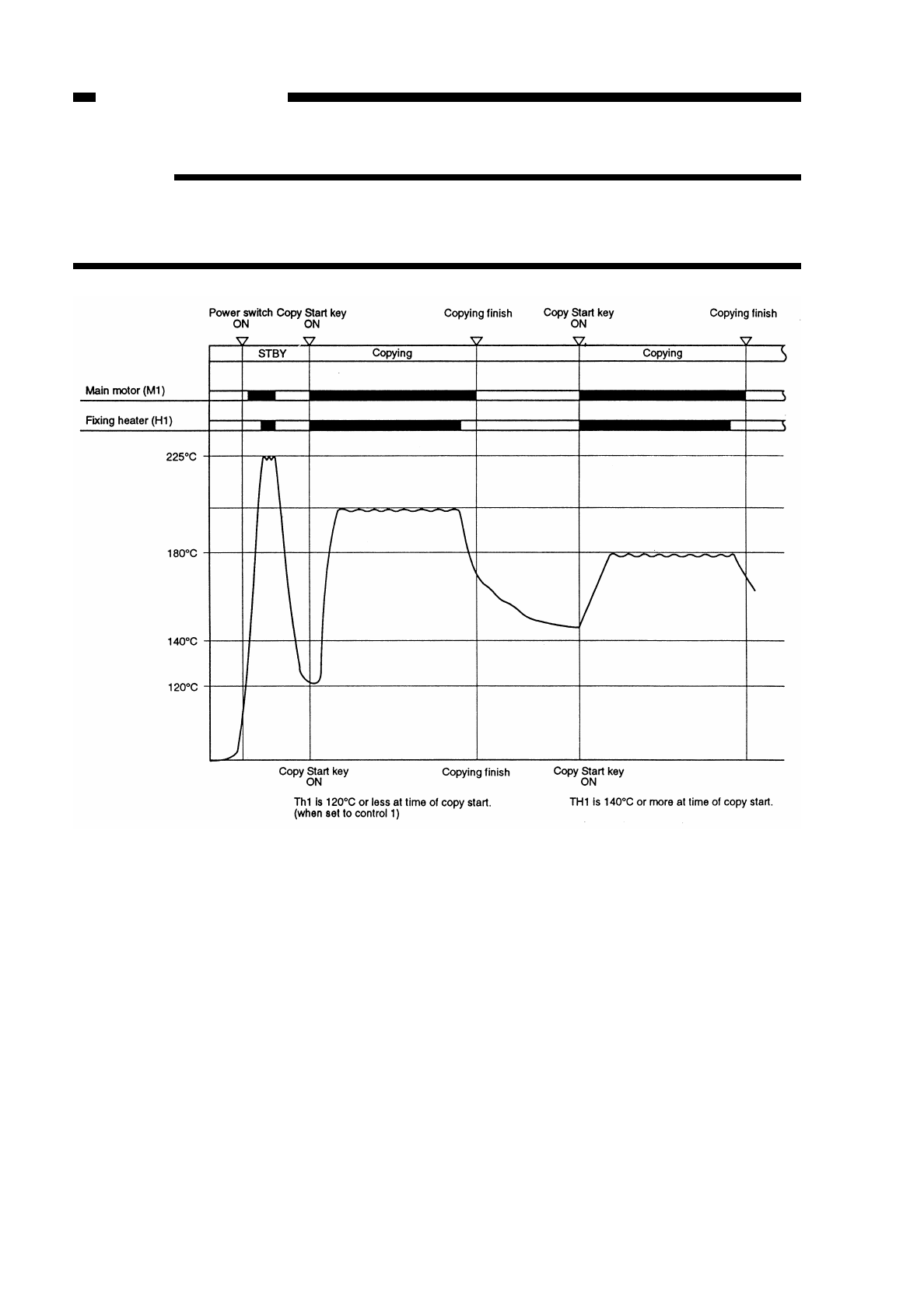
Reference:
Normally, control 2 is used. Use control 1 to increase the control temperature if a
fixing fault occurs; or use control 3 to lower the control temperature if offset occurs.
(See the p. 10-32.)
Figure 6-103
COPYRIGHT
©
1997 CANON INC. CANON NP6218 REV. 0 MAY 1997 PRINTED IN JAPAN (IMPRIME AU JAPON)
CHAPTER 6 FIXING SYSTEM
6-4
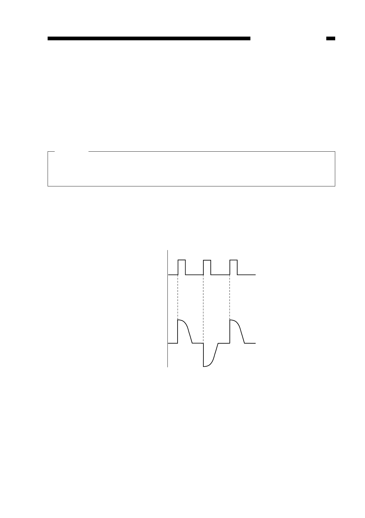
C. Controlling the Supply Power for the Fixing Heater
The temperature of the fixing heater is controlled by controlling the power supplied
to the fixing heater.
The resistance of the plane-shaped heater used as the fixing heater may show some
variation depending on which production lot it comes from.
For this reason, whenever you have replaced the copier’s heater, you must store the
resistance value in service mode (No. 304; see p. 10-31); this way, the microprocessor
on the DC controller PCB can exert proper control over power.
Caution:
The resistance of the fixing heater is stored in service mode at the time the copier
is shipped out of the factory; do not change it unless you have replaced the fixing
heater.
The power of the fixing heater is controlled by a phase power control method.
The microprocessor controls the output timing of the fixing heater drive signal
(HTRD) so that power that suits the target temperature of the fixing heater may be
supplied to the heater (potential control of the supply power).
Figure 6-104
COPYRIGHT
©
1997 CANON INC. CANON NP6218 REV. 0 MAY 1997 PRINTED IN JAPAN (IMPRIME AU JAPON)
CHAPTER 6 FIXING SYSTEM
6-5
HTRD
Supply power
to heater

D. Detecting Overheating at the End of the Fixing Heater
A sub thermistor (TH2) is provided at the end (rear) of the copier’s fixing heater to
monitor overheating.
This consideration to prevent damage to the fixing film caused by overheating of the
area where paper (smaller than B4) does not come into contact.
When TH2 registers 250°C or more, the distance between copies is increased to
facilitate discharge of heat by the fixing heater, thereby preventing overheating.
The copier continues to make copies maintaining such a distance even after TH2
registers a value lower than 250°C.
If the temperature further increases after the distance has been increased and if the
value reaches 260°C or more, the ongoing copying operation will be stopped and the
power will be cut off; at the times E001 information is stored. (See p. 10-109.)
E. Protection Mechanism
The copier is equipped with the following protective functions to prevent malfunction
of the fixing heater:
1. Thermistor (TH1, TH2)
1) The microprocessor on the DC controller monitors the voltage of the thermistor (TH1,
TH2); if it detects a high or low temperature error, it stops the power to the heater and
cuts off all the power. At the time, E000 thorugh E003 information is stored. (See p.
10-109.)
2) If the overheating detection circuit identifies that TH1 has registered 260°C or TH2
has registered 270°C for 0.3 sec or more, the heater error detection signal (HTNG)
turns off the relay (RL101) to stop power to the fixing heater and cut off all the power.
(See p. 10-109.)
Caution:
Be sure to disconnect the connector (J4) of the fixing heater and press the service
switch (SW301) on the DC controller when turning on the power.
2. Thermal Fuse (FU1)
If the temperature around the thermal fuse remains 226°C or more for a specific
period of time, the fuse melts to cut off the power to the fixing heater.
3. Heater ON Detection Circuit
The period of time during which the fixing heater drive signal (HTRD) remains off is
detected; if an error is found, the power is cut off and E004 information is stored at the
time.
COPYRIGHT
©
1997 CANON INC. CANON NP6218 REV. 0 MAY 1997 PRINTED IN JAPAN (IMPRIME AU JAPON)
CHAPTER 6 FIXING SYSTEM
6-6
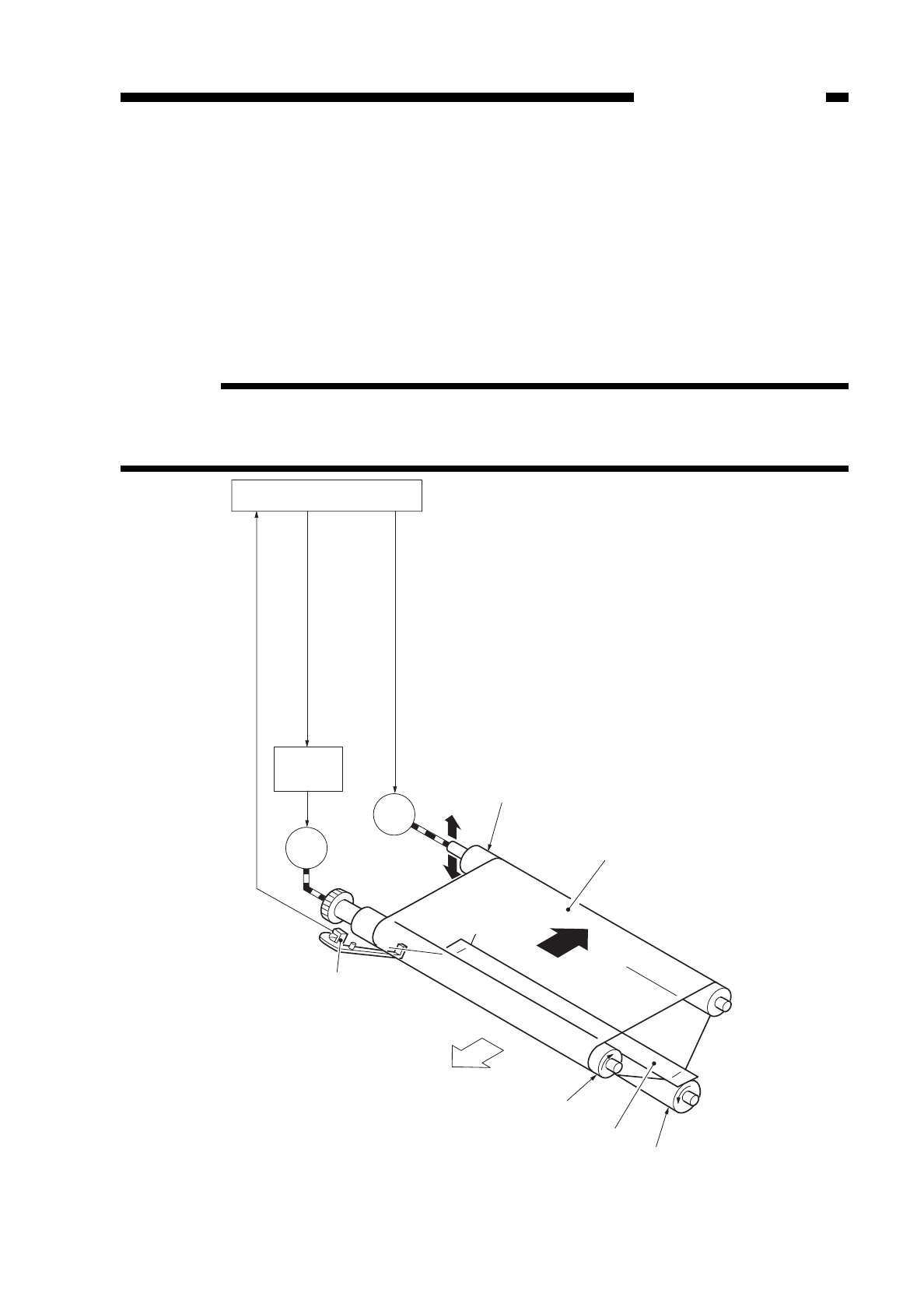
F. Correcting Displacement of the Fixing Film
1. Outline
The fixing film at times becomes displaced toward the front or rear as it keeps
turning. To correct such displacement, the copier is equipped with a correction
mechanism.
The control is executed by the fixing film sensor (PS9), which detects the position of
the film, and the fixing film motor (M4), which physically corrects displacement.
Reference:
If you turn on the power by inserting the door switch actuator into the door switch
with the top body of the copier open, E007 will be detected, since the condition
prevents the fixing film from turning.
Figure 6-105
COPYRIGHT
©
1997 CANON INC. CANON NP6218 REV. 0 MAY 1997 PRINTED IN JAPAN (IMPRIME AU JAPON)
CHAPTER 6 FIXING SYSTEM
6-7
M1
M4
Fixing film posision signal (FFD)
Main motor drive command (MMD)
Fuser film motor drive command (FMD)
DC controller PCB
Main motor
driver PCB
Tension roller
Fixing film
Fixing film motor
Main motor
Fixing film sensor
Delivery
Driver roller
Fixing heater
Pressure roller
(front)
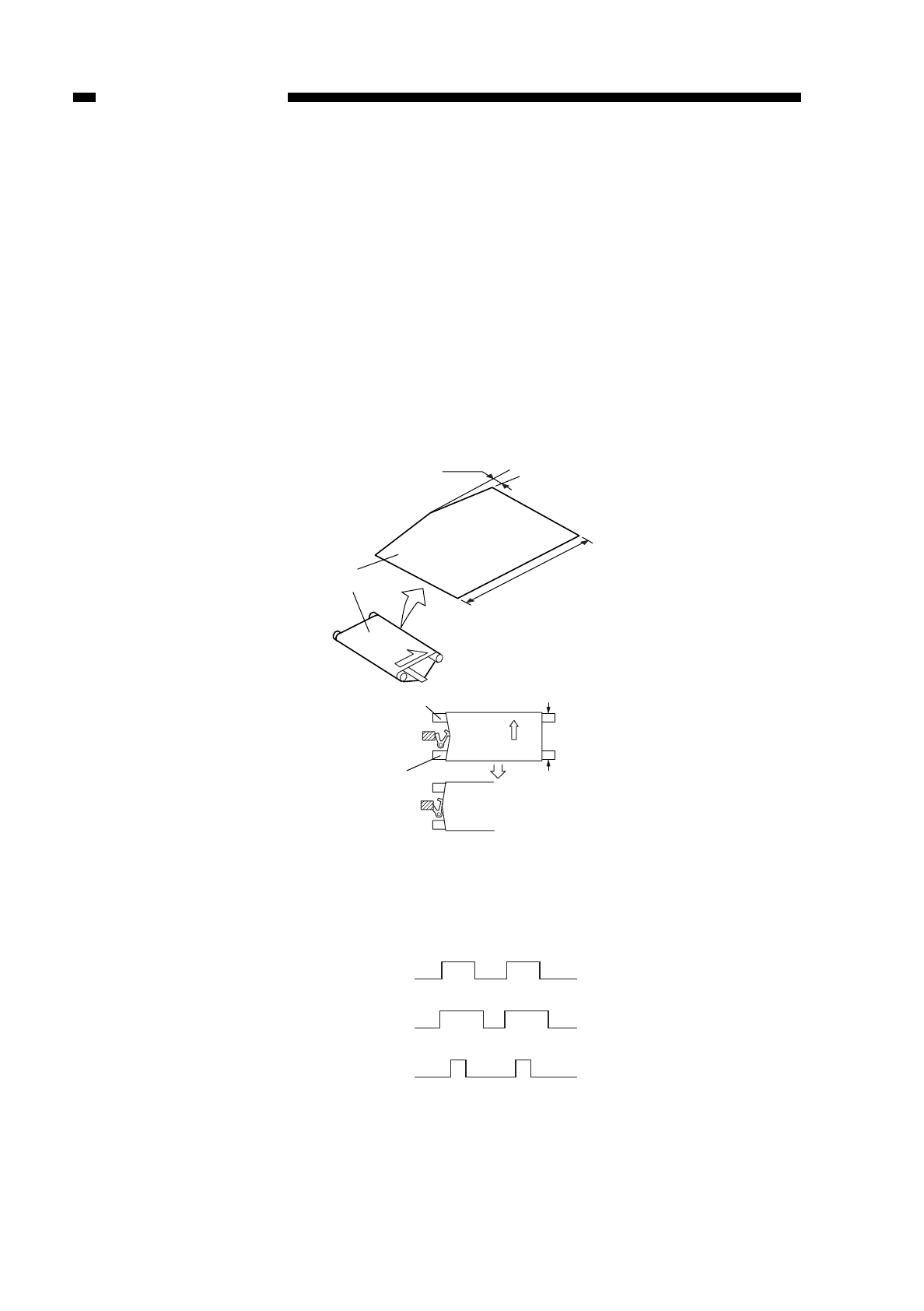
The fixing film sensor (PS9) is used to detect the position of the fixing film and found
at the end of the film.
The rear (sensor side) of the fixing film is provided with a cut as shown in Figure 6-
106 so that the fixing film sensor continuously goes on and off.
Normally, the on and off periods of the sensor are identical as long as the fixing film
remains centered.
If the film starts to become displaced toward the rear, however, the on period
becomes longer; the off period becomes longer if the film starts to be displaced toward
the front. (See Figure 6-107)
The DC controller monitors the on and off periods of the sensor and computes the
difference to correct the position of the fixing film.
Figure 6-106
Figure 6-107
COPYRIGHT
©
1997 CANON INC. CANON NP6218 REV. 0 MAY 1997 PRINTED IN JAPAN (IMPRIME AU JAPON)
CHAPTER 6 FIXING SYSTEM
6-8
(unit: mm) 5
142
Fixing film
(rear)
(front)
Tension roller
Drive roller
ON
OFF
Normal
(rear)
(front)
ON
OFF
ON
OFF
ON
OFF
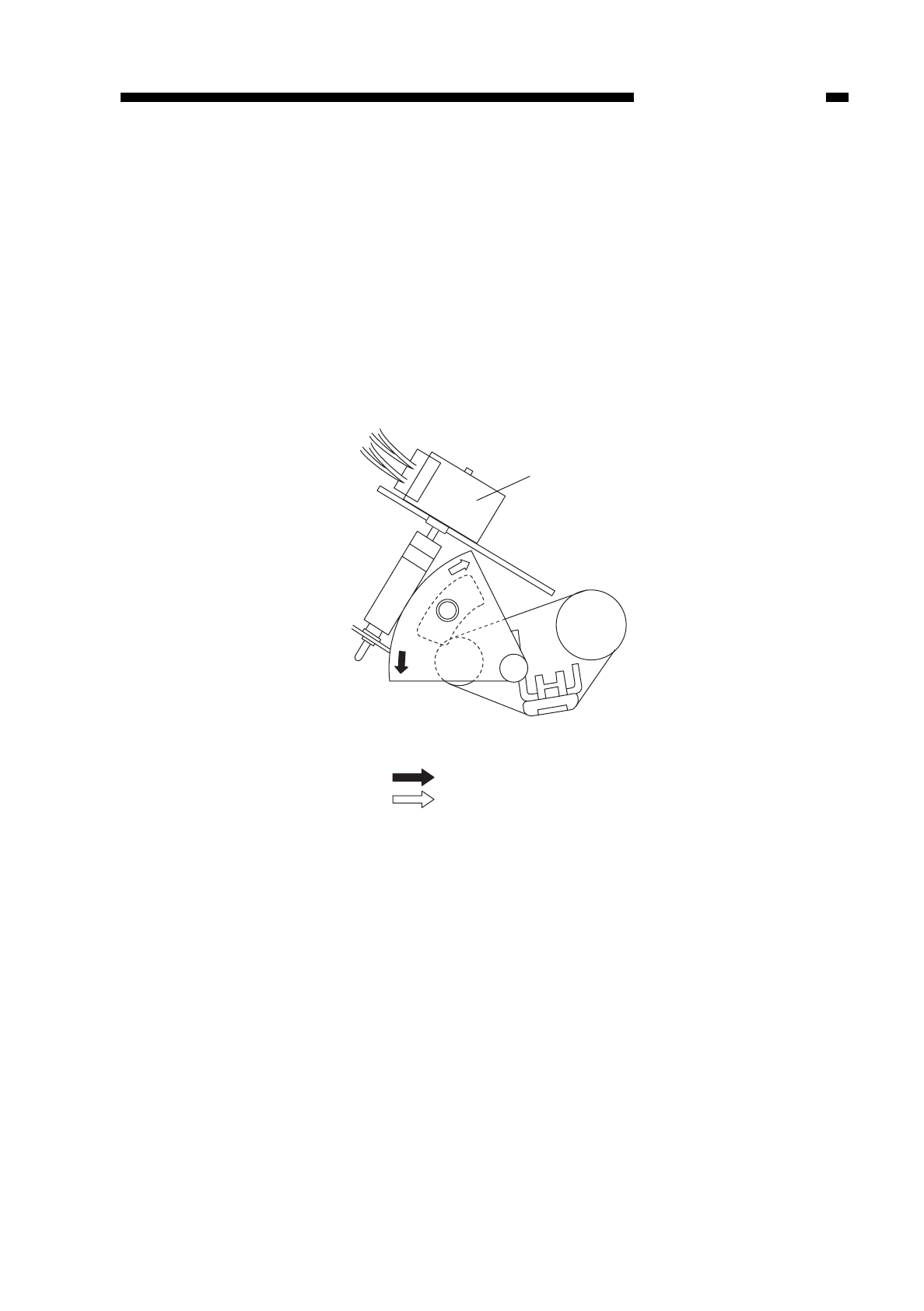
Displacement of the fixing film is physically corrected by the fixing film motor (M4).
When it identifies displacement of the fixing film, the DC controller rotates the fixing
film motor to move the rear of the tension roller up and down, thereby moving the fixing
film to the center to correct the displacement.
When the fixing film becomes displaced toward the rear, the tension roller is moved
down to move the fixing film toward the front.
When the fixing film becomes displaced toward the front, on the other hand, the
tension roller is moved up to move the fixing film toward the rear.
The fixing film is positioned properly by repeating these operations as necessary. If
the film has become displaced so much that the mechanism fails to make adequate
correction, ‘E007’ is indicated on the display. (See p. 10-110.)
Figure 6-108
COPYRIGHT
©
1997 CANON INC. CANON NP6218 REV. 0 MAY 1997 PRINTED IN JAPAN (IMPRIME AU JAPON)
CHAPTER 6 FIXING SYSTEM
6-9
Fixing belt motor (M4)
Tension roller
(rear view)
displacement to the rear
displacement to the front
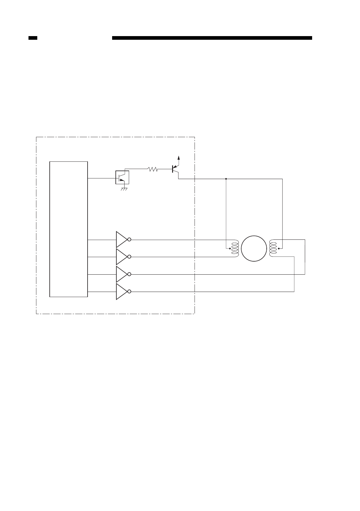
2. Controlling the Fixing Film Motor
The fixing film motor is a stepping motor, and is rotated by the drive signal FMD and
pulse signals FFA, FFA*, FFB, and FFB*.
When FMD is ‘1’, the drive voltage FFCA and FFBC are imposed; the motor starts
to rotate when pulses are applied to each phase in specific sequence.
The motor is rotated in reverse by applying these pulses in reverse order.
Figure 6-109
COPYRIGHT
©
1997 CANON INC. CANON NP6218 REV. 0 MAY 1997 PRINTED IN JAPAN (IMPRIME AU JAPON)
CHAPTER 6 FIXING SYSTEM
6-10
Microprocessor
(Q314)
FMD
FFA
FFA*
FFB
FFB*
DC controller PCB
+24V
FFCA FFCB
M4
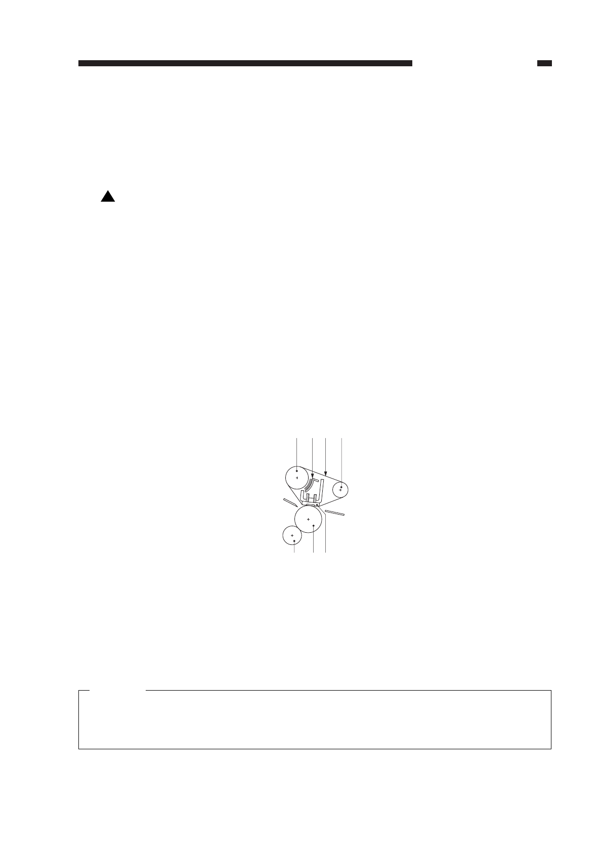
II. DISASSEMBLY AND ASSEMBLY
This section explains mechanical characteristics and describes how to
disassemble/assemble the machine.
Be sure to observe the following whenever disassemblig/assembling the machine:
1. Disconnect the power plug before starting the work.
2. Unless otherwise shown, assemble the parts by reversing the steps given to
disassemble them.
3. Identify each screw by type (length, diameter) and location.
4. A washer is used for one of the mounting screws on the rear cover to protect against
static electricity; be sure to use the washer when assembling the part.
5. A washer is used for some mounting screws (for grounding wire, varistor) to ensure
correct electrical continuity; be sure to use the washer when assembling the part.
6. As a rule, do not operate the machine while any of its parts are removed.
7. When sliding out the duplexing unit or the fixing assembly, be sure to turn off the front
door switch or the power switch.
A. Fixing Assembly
1. Construction1
qDrive roller tFixing cleaning roller
wCleaning brush yLower fixing roller
eFixing film uFixing heater
rTension rollerFigure 6-201
Caution:
The fixing film is made of special material; do not touch it or soil it.
If you must replace the upper fixing unit, replace it on a unit basis in the field and
leave component replacement to the workshop.
!
COPYRIGHT
©
1997 CANON INC. CANON NP6218 REV. 0 MAY 1997 PRINTED IN JAPAN (IMPRIME AU JAPON)
CHAPTER 6 FIXING SYSTEM
6-11
qwer
uyt
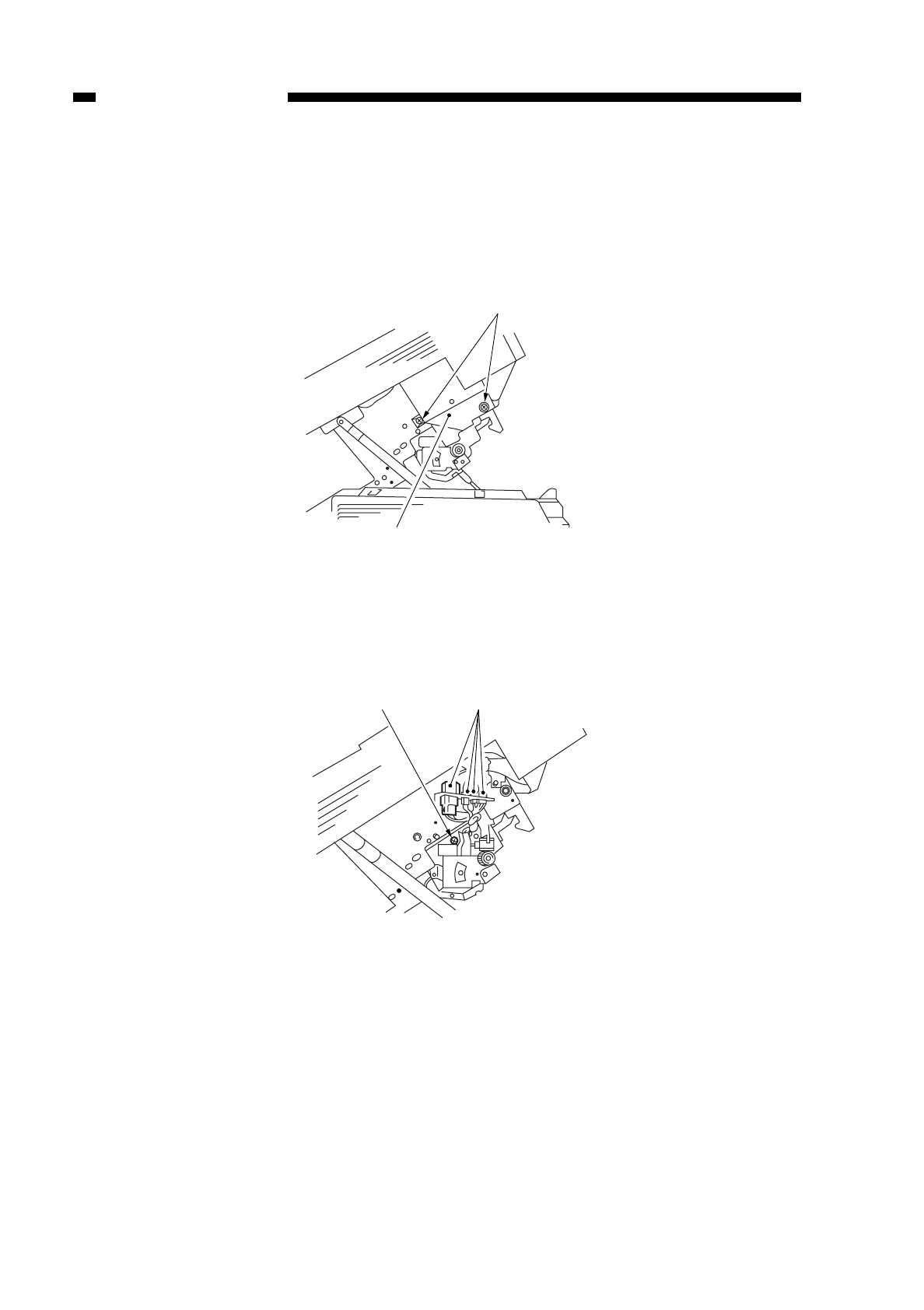
2. Detaching the Upper Fixing Unit
1) Open the copier’s front cover.
2) Open the copier’s top body.
3) Remove the two screws q, and detach the fixing assembly cover w.
Figure 6-202
4) Disconnect the four connectors e, and remove the screw r.
Figure 6-203
COPYRIGHT
©
1997 CANON INC. CANON NP6218 REV. 0 MAY 1997 PRINTED IN JAPAN (IMPRIME AU JAPON)
CHAPTER 6 FIXING SYSTEM
6-12
q
w
e
r
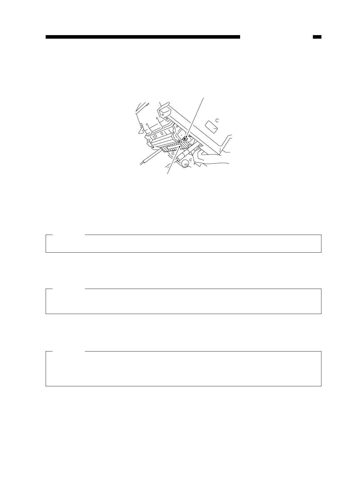
5) Open the fixing shutter t, and put the screw removed in step 4) into the hole yin
the front side plate.
Figure 6-204
6) Pull out the upper fixing unit toward the rear.
Caution:
Do not touch the fixing film.
3. Detaching the Fixing Film, Tension Roller, Drive Roller, Fixing Cleaning Brush,
and Fixing Heater Unit
Caution:
Before going through the steps, make sure that the heater and the heater connector
have cooled sufficiently.
1) Detach the upper fixing unit. (See “2. Detaching the Upper Fixing Unit on p. 6-12.”)
2) Remove the screw q, and detach the heater connector w(front).
Caution:
If you are removing the screw q, you must first make sure that the heater connector
has cooled.
The screw qis a special screw; take care not to drop it.
COPYRIGHT
©
1997 CANON INC. CANON NP6218 REV. 0 MAY 1997 PRINTED IN JAPAN (IMPRIME AU JAPON)
CHAPTER 6 FIXING SYSTEM
6-13
t
y
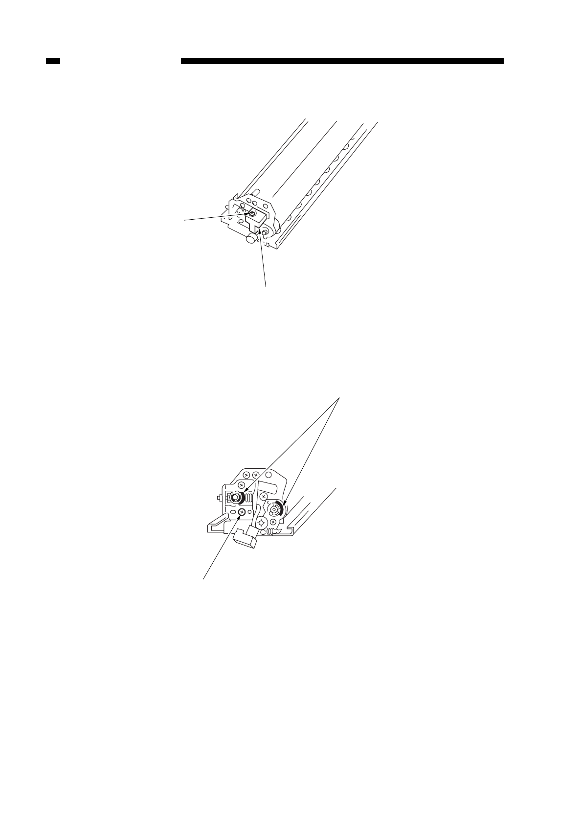
Figure 6-205
3) Remove the two E-rings eand the two washers r.
4) Remove the screw t.
Figure 6-206
COPYRIGHT
©
1997 CANON INC. CANON NP6218 REV. 0 MAY 1997 PRINTED IN JAPAN (IMPRIME AU JAPON)
CHAPTER 6 FIXING SYSTEM
6-14
q
w
er
t
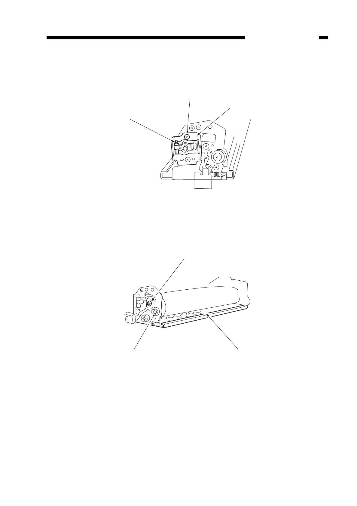
5) Release the pressure by positioning the screw tas shown in Figure 6-207.
6) Remove the screw y, and detach the bushing u.
Figure 6-207
7) Remove the screw i, and detach the bushing o; then, detach the upper fixing top
side plate !0.
Figure 6-208
COPYRIGHT
©
1997 CANON INC. CANON NP6218 REV. 0 MAY 1997 PRINTED IN JAPAN (IMPRIME AU JAPON)
CHAPTER 6 FIXING SYSTEM
6-15
u
t
y
!0
i
o
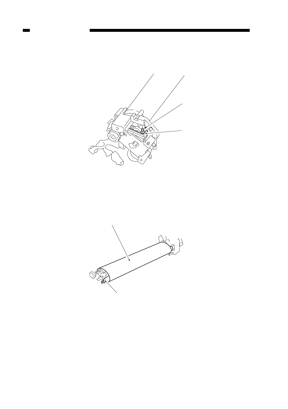
8) Release the pressure by positioning the screw yand the bushing (rear) as shown in
Figure 6-209.
Figure 6-209
9) Pull out the fixing film !2 toward the front.
10) Detach the tension roller !3.
Figure 6-210
COPYRIGHT
©
1997 CANON INC. CANON NP6218 REV. 0 MAY 1997 PRINTED IN JAPAN (IMPRIME AU JAPON)
CHAPTER 6 FIXING SYSTEM
6-16
y
!1
!2
!3
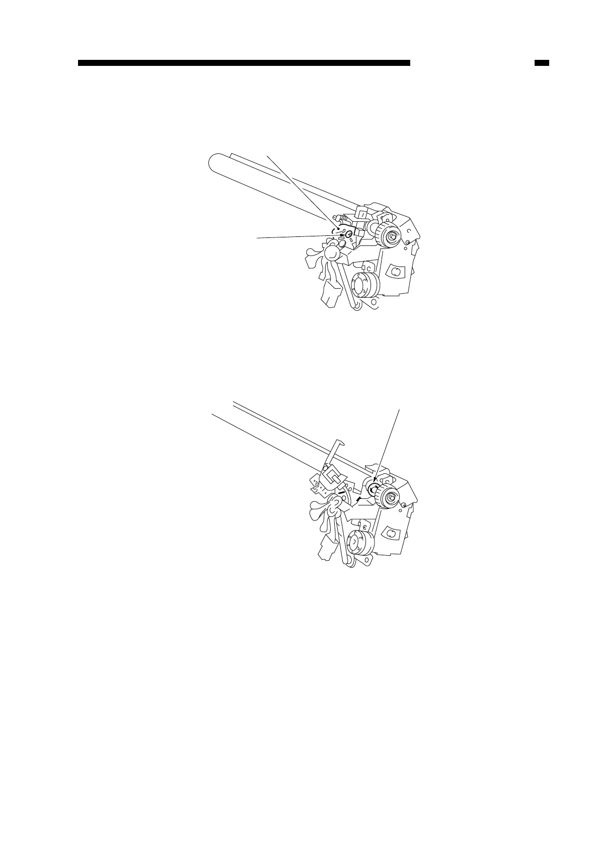
11) Remove the screw !4, and detach the fixing film sensor !5.
Figure 6-211
12) Remove the E-ring !6.
Figure 6-212
COPYRIGHT
©
1997 CANON INC. CANON NP6218 REV. 0 MAY 1997 PRINTED IN JAPAN (IMPRIME AU JAPON)
CHAPTER 6 FIXING SYSTEM
6-17
!4
!5
!6
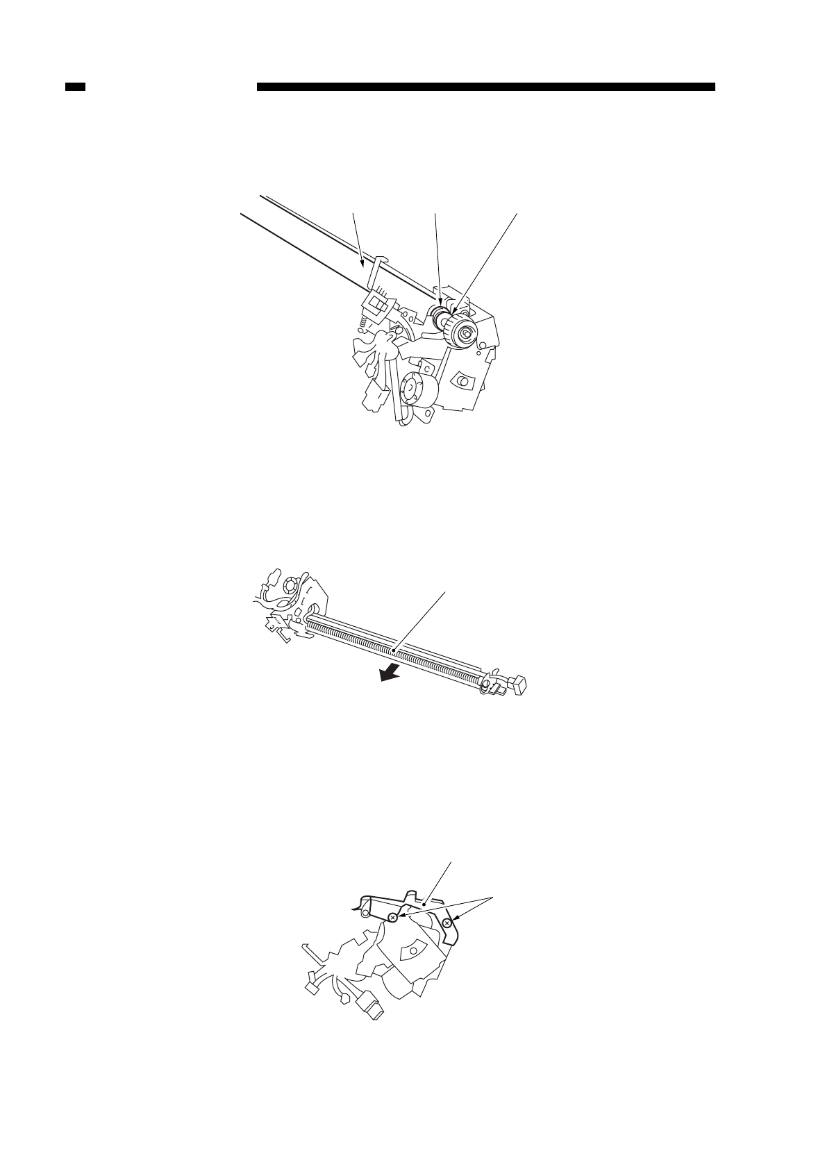
13) Remove the washer !7 and the bushing !8, and detach the drive roller !9.
Figure 6-213
14) Life the delivery side, and detach the fixing cleaning brush @0.
Figure 6-214
15) Remove the two screws @1, and detach the cover @2.
Figure 6-215
COPYRIGHT
©
1997 CANON INC. CANON NP6218 REV. 0 MAY 1997 PRINTED IN JAPAN (IMPRIME AU JAPON)
CHAPTER 6 FIXING SYSTEM
6-18
!7
!8
!9
@0
@2
@1
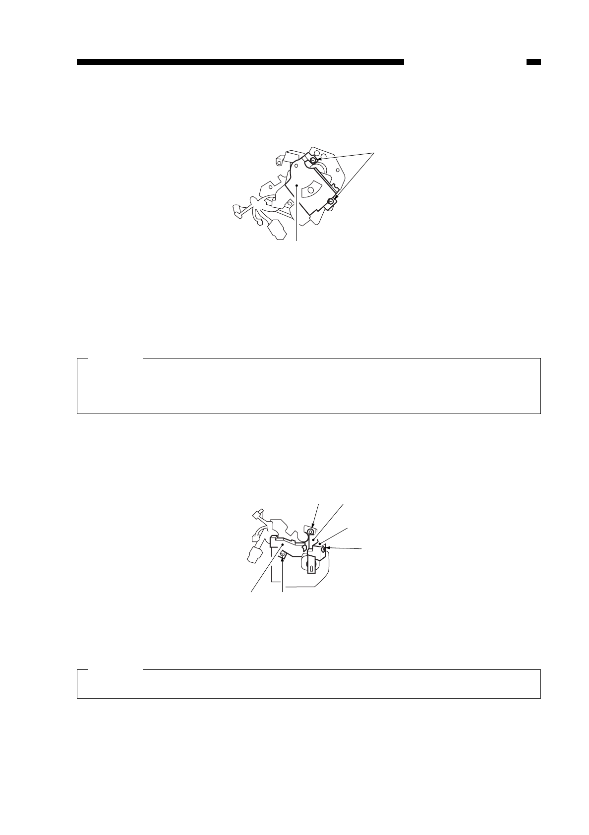
COPYRIGHT
©
1997 CANON INC. CANON NP6218 REV. 0 MAY 1997 PRINTED IN JAPAN (IMPRIME AU JAPON)
CHAPTER 6 FIXING SYSTEM
6-19
16) Remove the two screws @3, and detach the fixing film motor unit @4.
Figure 6-216
17) Remove the screw @5, and detach the cover @6.
18) Remove the screw @7, and disconnect the heater connector @8.
Caution:
If you are removing the screw @7, you must first make sure that the heater connector
has cooled.
The screw @7 is a special screw; take care not to lose it.
19) Remove the C-ring @9, and detach the bushing #0, leaving the fixing heater behind.
Figure 6-217
Caution:
Do not touch the surface of the heater.
@4
@3
@8
@9 #0
@6
@7
@5
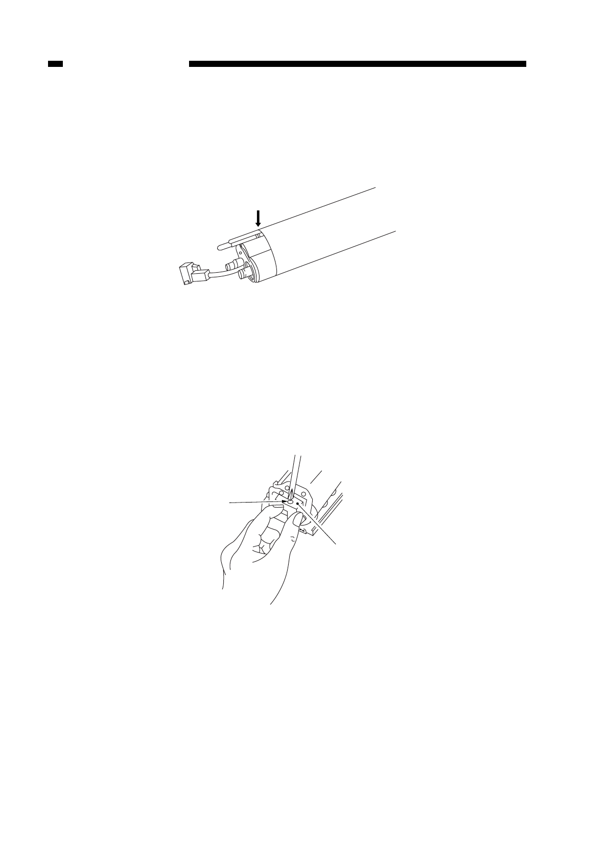
4. Points to Note When Attaching the Fixing Film
• Make sure that the cut off is toward the rear.
• Make sure that the front side is aligned with the groove of the heater.
Figure 6-218
5. Points to Note When Attaching the Heater Connector
• When attaching the heater connector to the fixing heater, take care not to damage the
heater.
• When tightening the screw, hold the connector taking care that its top and bottom are
free of pressure; be careful not to tighten the screw excessively.
Figure 6-219
COPYRIGHT
©
1997 CANON INC. CANON NP6218 REV. 0 MAY 1997 PRINTED IN JAPAN (IMPRIME AU JAPON)
CHAPTER 6 FIXING SYSTEM
6-20
Film edge
Screw
Heater connector
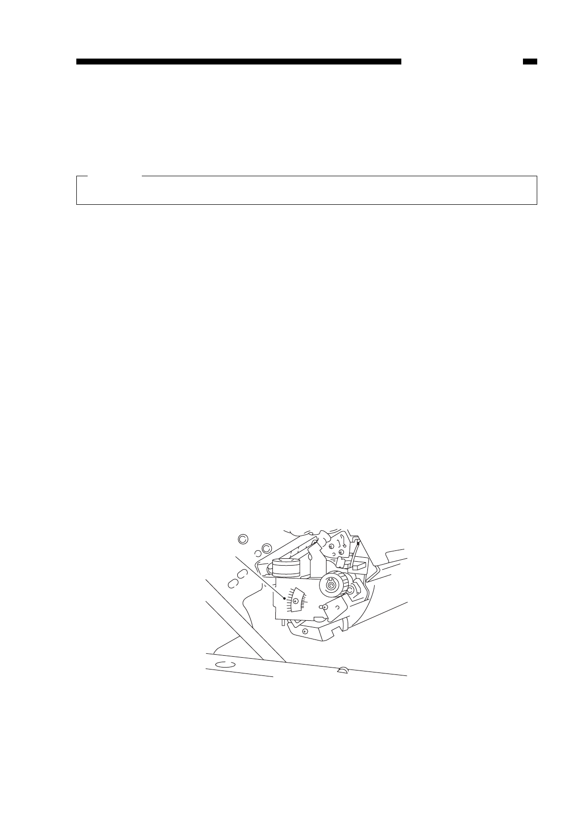
6. Points to Note When Replacing the Fixing Upper Unit
• If you have replaced the upper fixing unit, you must store the resistance of the heater
in service mode (No. 304; see p. 10-31.)
Caution:
Do not touch the surface of the heater.
7. Adjusting the Fixing Film Drive Roller Pressure
If a fixing fault occurs, be sure to go through the following to adjust the pressure of
the drive roller.
1) Detach the fixing cover.
2) Detach the inside cover of the copier’s front side.
3) Close the copier’s upper body, and insert the door switch actuator.
4) Press the service mode switch (SW302).
• The copier enters service mode, and the display indicates ‘1’.
5) Press ‘4’ on the keypad.
• The display indicates ‘4’.
6) Press the AE key.
• The copier enters operation check mode, and the display indicates ‘401’.
7) Press ‘5’ on the keypad.
• The display indicates ‘405’.
8) Press the Start key.
• The copier enters fixing film initial rotation mode (405) to return the fixing film to its
proper position.
• The fixing film stops automatically as soon as it reaches its proper position.
• The copier indicates the position of the film in the copy density indicator.
9) Open the copier’s top body.
10) Check that the arrow qis at the middle of the memory as shown in Figure 6-220.
Figure 6-220 (rear view)
11) Close the copier’s top body, and activate service mode.
12) Press ‘4’ on keypad; when the display indicates ‘4’, press the AE key.
COPYRIGHT
©
1997 CANON INC. CANON NP6218 REV. 0 MAY 1997 PRINTED IN JAPAN (IMPRIME AU JAPON)
CHAPTER 6 FIXING SYSTEM
6-21
q
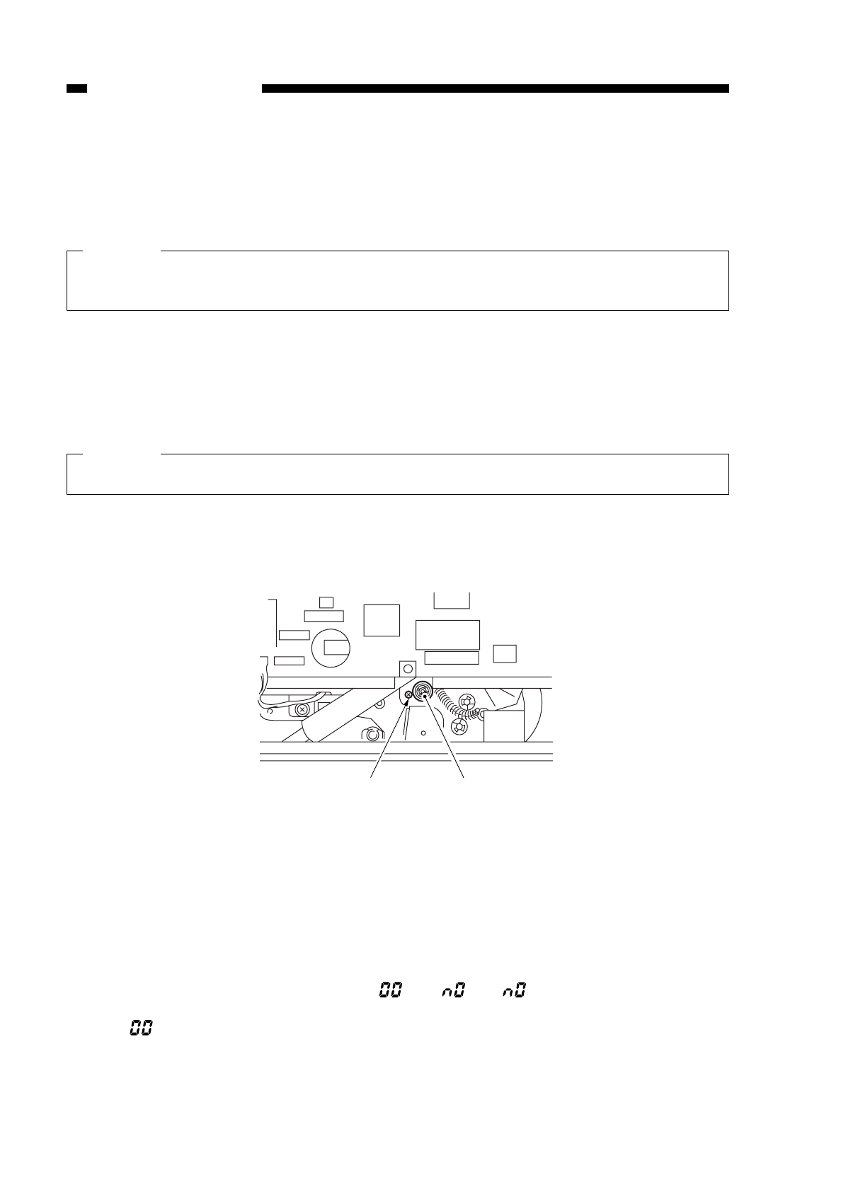
13) Press ‘4’ on the keypad; when the display indicates ‘404’, press the Start key.
• The copier enters fixing tension roller mode (404).
• The fixing tension roller becomes fixed, and the fixing film rotates idly.
• The count indicator indicates how long the fixing film sensor has remained on.
Caution:
If the copy count indicator keeps indicating ‘0’ or ‘528’ during adjustment,
immediately press the Stop key to de-activate service mode.
If the copy countis ‘180’ or higher and ‘348’ or lower and has not changed, go to step
17). Or, if 10’s and 100’s do not change, go to step 17);
14) Loosen the fixing screw wslightly; i.e., move it to the left about 1 mm.
15) Turn the adjusting screw eso that the copy count is ‘180’ or higher’ and ‘348’ or
lower.
Caution:
Adjust so that 10’s and 100’s will not change; ignore 1’s may change ±5.)
• A clockwise turn decreases the reading.
• A counterclockwise turn increases the reading.
Figure 6-221
16) When the reading in the copy counter is appropriately correct, tighten the screw w;
make sure that the reading is appropriate after tightening the screw.
17) Press the Start key.
• The copier enters check mode (404), and the fixing film rotates idly for about 2.5
min; check that the fixing film has not shifted from the adjusted position.
• The copy count indicator indicates “ ” or “ ”; if “ ” is indicated, repeat steps
starting with 13).
If “ ” is indicated, repeat steps 4) through 10).
18) Attach the cover.
COPYRIGHT
©
1997 CANON INC. CANON NP6218 REV. 0 MAY 1997 PRINTED IN JAPAN (IMPRIME AU JAPON)
CHAPTER 6 FIXING SYSTEM
6-22
e
w
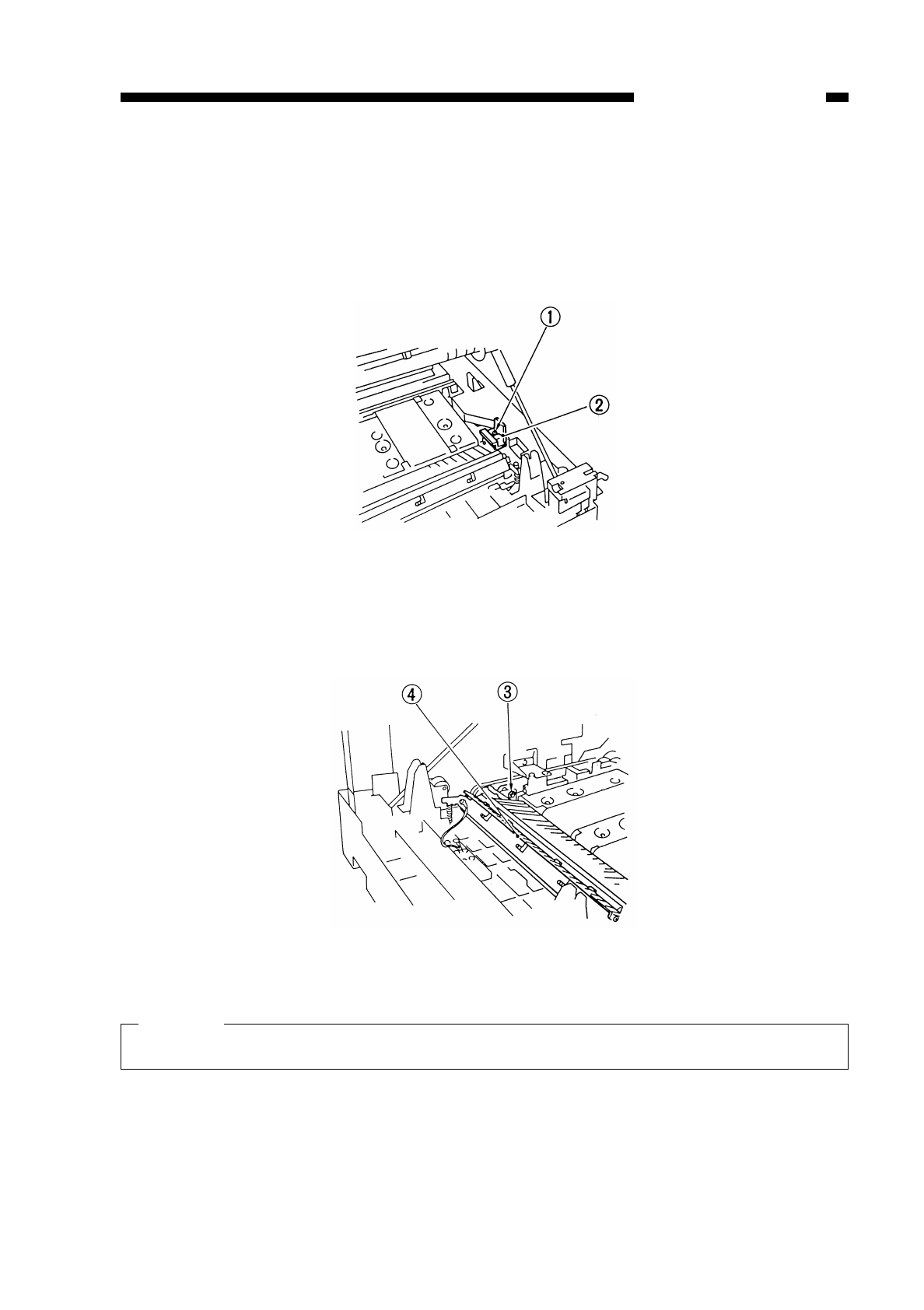
8. Detaching the Lower Fixing Unit
1) Detach the delivery roller. (See “1. Detaching the Delivery Roller.” on p. 6-28.)
2) Detach the delivery cover.
3) Remove the screw q, and detach the fixing shutter open/close block w.
Figure 6-222
4) Remove the E-ring e, and detach the lower fixing unit r.
Figure 6-223
Caution:
Do not touch the surface of the fixing cleaning roller or the lower fixing roller.
COPYRIGHT
©
1997 CANON INC. CANON NP6218 REV. 0 MAY 1997 PRINTED IN JAPAN (IMPRIME AU JAPON)
CHAPTER 6 FIXING SYSTEM
6-23
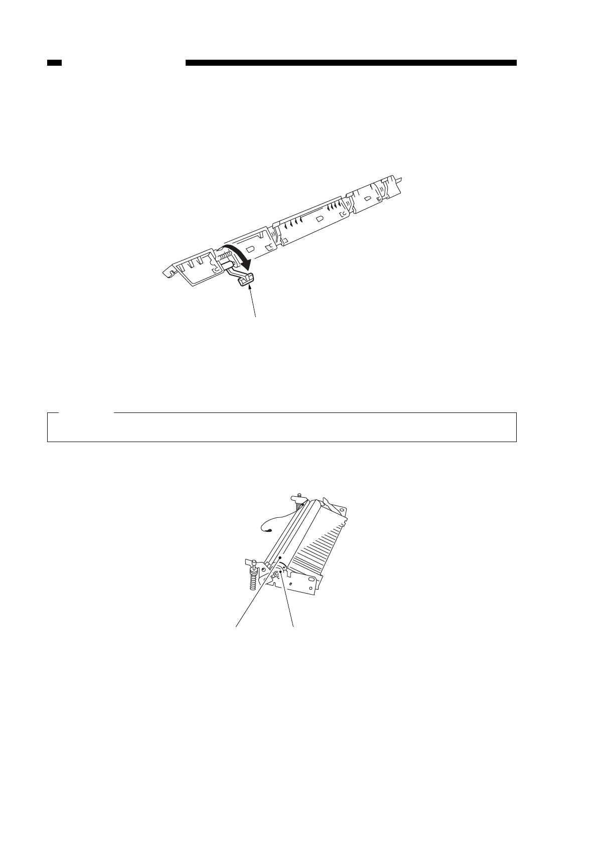
9. Detaching the Separation Claw/Lower Fixing Claw and Fixing Cleaning Roller
1) Detach the front door.
2) Remove the screw q, and detach the separation claw unit w.
Figure 6-224
3) Detach the separation claw efrom the separation claw unit.
Caution:
Take care not to misplace the spring.
4) Detach the lower fixing roller rtogether with the bushing t.
Figure 6-225
COPYRIGHT
©
1997 CANON INC. CANON NP6218 REV. 0 MAY 1997 PRINTED IN JAPAN (IMPRIME AU JAPON)
CHAPTER 6 FIXING SYSTEM
6-24
e
r
e
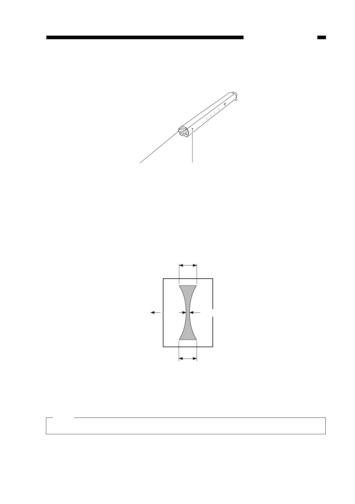
5) Detach the bushing yfound at the front, and detach the HIGH-TEMPERATURE
WARNING cover u.
Figure 6-226
6) Lift the fixing cleaning roller to detach.
10. Adjusting the Lower Fixing Roller Nip
If fixing faults occur, make the following adjustments.
The nip is correct if as shown below; otherwise, turn the bolt to make adjustments.
Figure 6-227
Note:
a and c represent points 10 mm from both ends of copy paper.
COPYRIGHT
©
1997 CANON INC. CANON NP6218 REV. 0 MAY 1997 PRINTED IN JAPAN (IMPRIME AU JAPON)
CHAPTER 6 FIXING SYSTEM
6-25
·········
········· ·········
········· ·········
········· ·········
·········
u
y
c
a
A4 size
Feeding
direction b Center of paper
b : 4±1mm
| a-c | : 1mm or less

a. Measuring the Nip
Measure the nip immediately after turning on the copier before the beginning of a
work day.
1) Open the copyboard cover, and make a solid black copy in A4.
2) Place the copy in the multifeeder with the solid black face up.
3) Press the service mode switch (SW302) using a hex key.
• The copier enters service mode, and the display indicates ‘1’.
4) Press ‘4’ on the keypad.
• The display indicates ‘4’.
5) Press the AE key.
• The copier enters operation/check mode, and the display indicates ‘401’.
6) Press ‘6 on the keypad.
• The display indicates ‘406’.
7) Press the Start key.
• The above operations cause the multifeeder to pick up paper so that you can take
measurements as in Figure 6-227; the paper will then be discharged.
Reference:
The copy paper stops while it is half way under the fixing roller; and, about 10 sec
later, it will be automatically discharged.
8) Measure the nip.
COPYRIGHT
©
1997 CANON INC. CANON NP6218 REV. 0 MAY 1997 PRINTED IN JAPAN (IMPRIME AU JAPON)
CHAPTER 6 FIXING SYSTEM
6-26
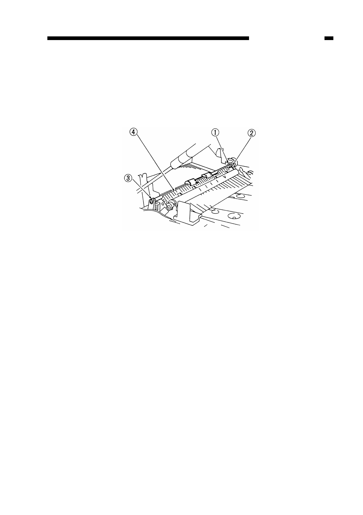
B. Delivery Assembly
1. Detaching the Delivery Roller
1) Open the copier’s top body.
2) Remove the E-ring q.
3) Shift the bushing w(rear) and bushing e(front); then, detach the delivery roller r.
Figure 6-228
COPYRIGHT
©
1997 CANON INC. CANON NP6218 REV. 0 MAY 1997 PRINTED IN JAPAN (IMPRIME AU JAPON)
CHAPTER 6 FIXING SYSTEM
6-27

COPYRIGHT
©
1997 CANON INC. CANON NP6218 REV. 0 MAR. 1997 PRINTED IN JAPAN (IMPRIME AU JAPON)
CHAPTER 6 FIXING SYSTEM
6-28

CHAPTER 7
EXTERNALS/AUXILIARY MECHANISMS
I. POWER SUPPLY ...............................7-1
A. Outline ...........................................7-1
B. Power Supply Circuit Assembly.....7-2
C. Detecting Errors in the Power
Supply PCB ...................................7-4
D. Protection Mechanisms for the
Power Supply Circuit .....................7-5
II. DISASSEMBLY AND ASSEMBLY ......7-6
A. External Covers.............................7-6
B. Control Panel.................................7-9
C. Fans...............................................7-10
D. Main Motor/Main Drive Assembly..7-11
E. Cassette unit .................................7-14
F. DC Controller PCB ........................7-17
G. Composite Power Supply PCB......7-18
H. AE Sensor PCB.............................7-21
I. Intensity Sensor PCB ....................7-21
This chapter shows the copier’s external parts, and explains the principles used for the copier’s
various control mechanisms in view of the functions of electrical and mechanical units and in relation
to their timing of operation. It also shows how these units may be disassembled/assembled and
adjusted.
COPYRIGHT
©
1997 CANON INC. CANON NP6218 REV. 0 MAY 1997 PRINTED IN JAPAN (IMPRIME AU JAPON)
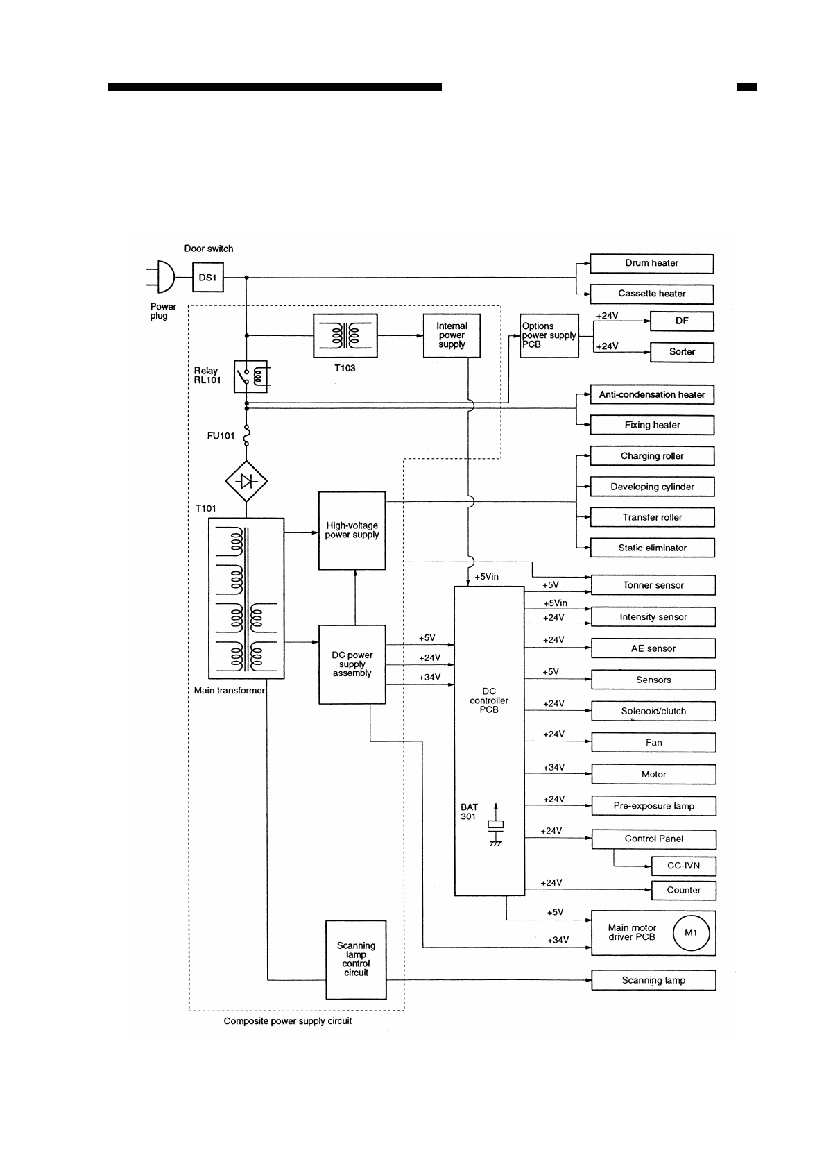
CHAPTER 7 EXTERNALS/AUXILIARY MECHANISMS
COPYRIGHT
©
1997 CANON INC. CANON NP6218 REV. 0 MAY 1997 PRINTED IN JAPAN (IMPRIME AU JAPON)
7-1
I. POWER SUPPLY
A. Outline
Figure 7-101

COPYRIGHT
©
1997 CANON INC. CANON NP6218 REV. 0 MAY 1997 PRINTED IN JAPAN (IMPRIME AU JAPON)
7-2
CHAPTER 7 EXTERNALS/AUXILIARY MECHANISMS
B. Power Supply Circuit Assembly
The copier’s power supply assembly is a composite power supply circuit which uses
a single main transformer (T101) as the source of DC power, high-voltage power, and
power for the fluorescent lamp.
AC power is supplied to the DC power supply assembly when the power switch
(SW829) and the door switch are turned on.
When the power switch on the control panel is pressed, signals are sent to the
composite power supply assembly to generate internal power supply +5 Vin.
In response, the microprocessor (Q512) turns on to turn on relays RL101 and RL501
to supply power.
The DC power supply generates +34 V, +24 V, and +5 V.
When the power switch is pressed for a second time, the microprocessor turns off
RL501 and the main transformer; thereafter, it turns off Q503 to turn off RL101, thereby
cutting off +5 Vin.
The condition deprives the DC controller circuit of DC power; to compensate for the
absence of power, a lithium battery (BAT301) is provided to back up the data in the RAM
(Q307) in the DC controller circuit.
Caution:
Voltage is supplied up to the AC power supply even when the power is off.
Caution:
Replace the lithium battery only with the one listed in the Parts Catalog. Use of a
different battery may present a risk of fire or explosion. The battery may present a
fire or chemical burn hazard if mistreated. Do not recharge, disassemble, or
dispose of it in fire.
Keep the battery out of reach of children and discare any used battery promptly.
Reference:
The tolerances for the DC voltage are as follows:
• +34 V ±20%
• +24 V ±5%
• + 5 V ±5%
However, the above applies only when the error in the AC input is limited to ±10%.
!
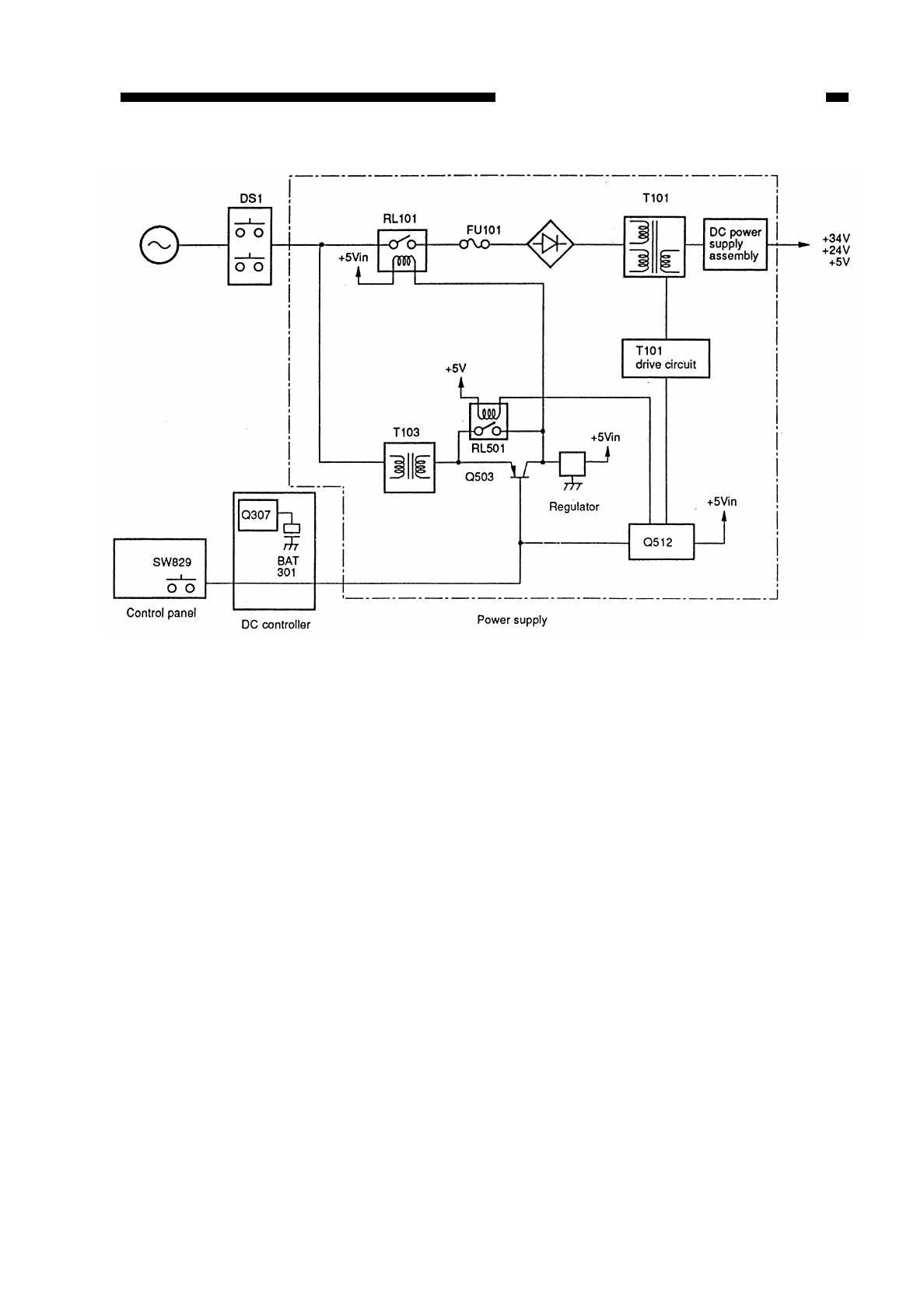
Figure 7-102
COPYRIGHT
©
1997 CANON INC. CANON NP6218 REV. 0 MAY 1997 PRINTED IN JAPAN (IMPRIME AU JAPON)
7-3
CHAPTER 7 EXTERNALS/AUXILIARY MECHANISMS

C. Detecting Errors in the Power Supply PCB
The microprocessor (Q512) on the composite power supply PCB either displays an
error message on the display by communicating with the DC controller or flashes
LED501 to indicate the presence of an error if any of the following is identified.
1. Communication Error between DC Controller PCB and Composite Power
Supply PCB
If an error occurs in the communication between the DC controller PCB and the
composite power supply PCB, E240 is indicated as soon as it is detected by the
microprocessor on the DC controller PCB. If an error is detected by the composite power
supply, the LED is flashed at intervals of 5 sec.
2. Error in the High-Voltage Output Data
If the difference between the setting associated with the high voltage generated by
the microprocessor (Q512) on the composite power supply PCB and the control value is
greater than the specified value, the microprocessor (Q512) sends error data to the DC
controller PCB, which in turn indicates E064.
3. Low-Voltage Output Data Error
If the difference between the setting associated with the low voltage generated by the
microprocessor (Q512) on the composite power supply PCB and the control value is
greater than the specified value, the microprocessor (Q512) communicates with the DC
controller PCB, which in turn indicates E803.
4. Overcurrent in the Low-voltage Power Supply
If the composite power supply PCB identifies overcurrent because of an error in a DC
load or wire is trapped, the LED is flashed at intervals of 2 sec for 20 sec.
Reference:
Normally, the LED is flashing at intervals of 0.5 sec.
COPYRIGHT
©
1997 CANON INC. CANON NP6218 REV. 0 MAY 1997 PRINTED IN JAPAN (IMPRIME AU JAPON)
7-4
CHAPTER 7 EXTERNALS/AUXILIARY MECHANISMS

CHAPTER 7 EXTERNALS/AUXILIARY MECHANISMS
D. Protection Mechanisms for the Power Supply Circuit
The composite power supply PCB is equipped with an overcurrent detection circuit;
if a short circuit occurs in a load for some reason, the protection mechanism is activated
to stop the output.
When the output is cut out, you may reset the output by opening the front door to turn
off the door switch, correcting the load, and turning on the door switch and power switch
(SW829) once again.
Caution:
Be sure to disconnect the connector (J4) of the fixing heater before resetting the
output.
Repeated short circuiting and resetting can cause the built-in fuse (FU101) to blow.
COPYRIGHT
©
1997 CANON INC. CANON NP6218 REV. 0 MAY 1997 PRINTED IN JAPAN (IMPRIME AU JAPON)
7-5
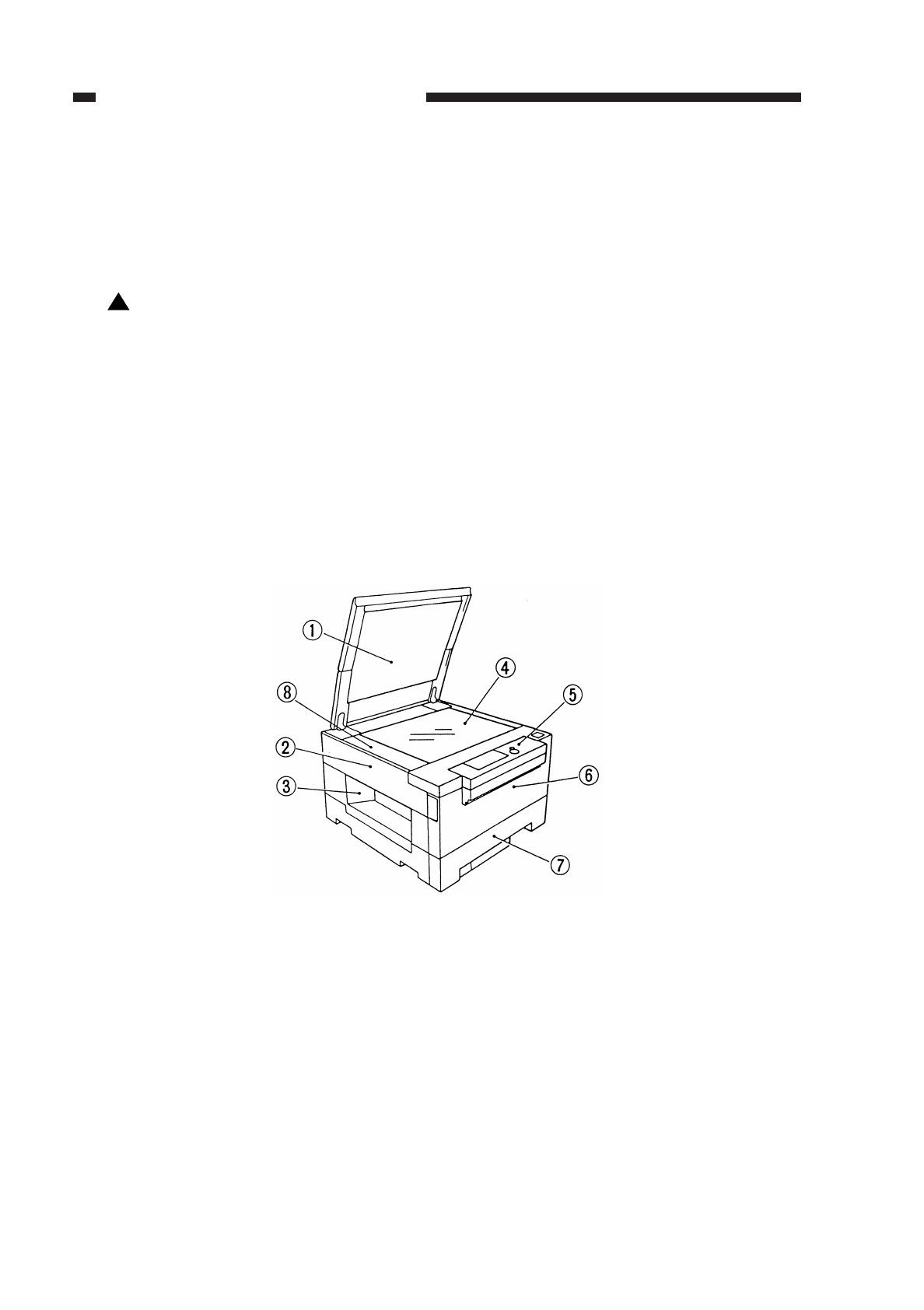
II. DISASSEMBLY AND ASSEMBLY
This section explains mechanical characteristics and describes how to
disassemble/assemble the machine.
Be sure to observe the following whenever disassemblig/assembling the machine:
1. Disconnect the power plug before starting the work.
2. Unless otherwise shown, assemble the parts by reversing the steps given to
disassemble them.
3. Identify each screw by type (length, diameter) and location.
4. A washer is used for one of the mounting screws on the rear cover to protect against
static electricity; be sure to use the washer when assembling the part.
5. A washer is used for some mounting screws (for grounding wire, varistor) to ensure
correct electrical continuity; be sure to use the washer when assembling the part.
6. As a rule, do not operate the machine while any of its parts are removed.
7. When sliding out the duplexing unit or the fixing assembly, be sure to turn off the front
door switch or the power switch.
A. External Covers
qCopyboard cover tControl panel
wLeft cover yFront door
eDelivery cover uCassette
rCopyboard iUpper left cover
Figure 7-201
!
COPYRIGHT
©
1997 CANON INC. CANON NP6218 REV. 0 MAY 1997 PRINTED IN JAPAN (IMPRIME AU JAPON)
7-6
CHAPTER 7 EXTERNALS/AUXILIARY MECHANISMS
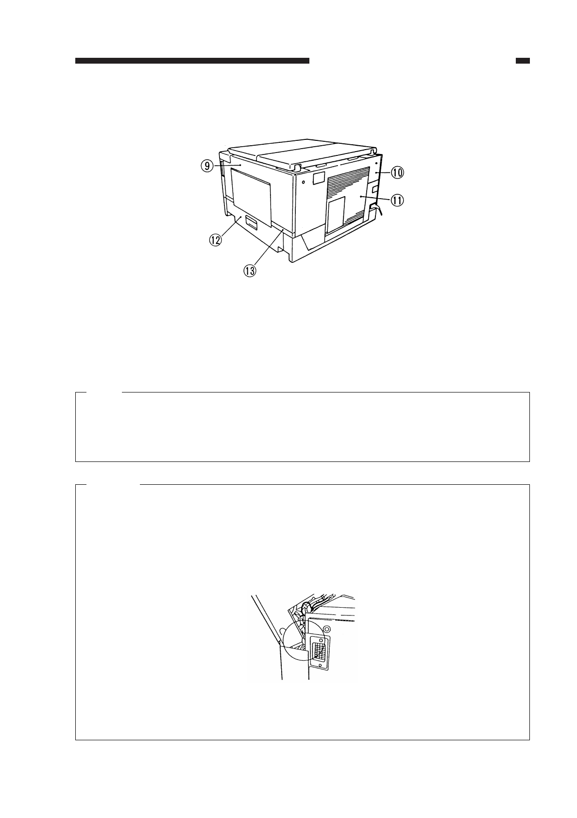
oRight cover !2 Lower right cover
!0 Upper rear cover !3 Lower right back
!1 Rear cover
Figure 202 cover
Note:
Detach the covers when cleaning, inspecting, or repairing the inside of the copier
as necessary.
Covers that may be detached merely by removing their respective mounting screws
are omitted from the discussion.
Caution:
When attaching the rear cover, be sure that the harness is housed inside the upper
rear cover so that its portion shown in the diagram will not spring out the cover or
the harness will not come into contact with the connector plate.
Figure 7-203
COPYRIGHT
©
1997 CANON INC. CANON NP6218 REV. 0 MAY 1997 PRINTED IN JAPAN (IMPRIME AU JAPON)
7-7
CHAPTER 7 EXTERNALS/AUXILIARY MECHANISMS
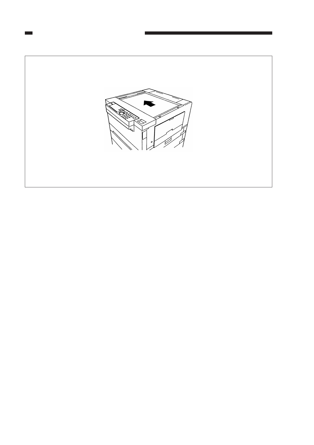
When attaching the copyboard glass, make sure that it is firmly in contact with the
vertical size plate without a gap to prevent intrusion of foreign matter.
Figure 7-204
COPYRIGHT
©
1997 CANON INC. CANON NP6218 REV. 0 MAY 1997 PRINTED IN JAPAN (IMPRIME AU JAPON)
7-8
CHAPTER 7 EXTERNALS/AUXILIARY MECHANISMS
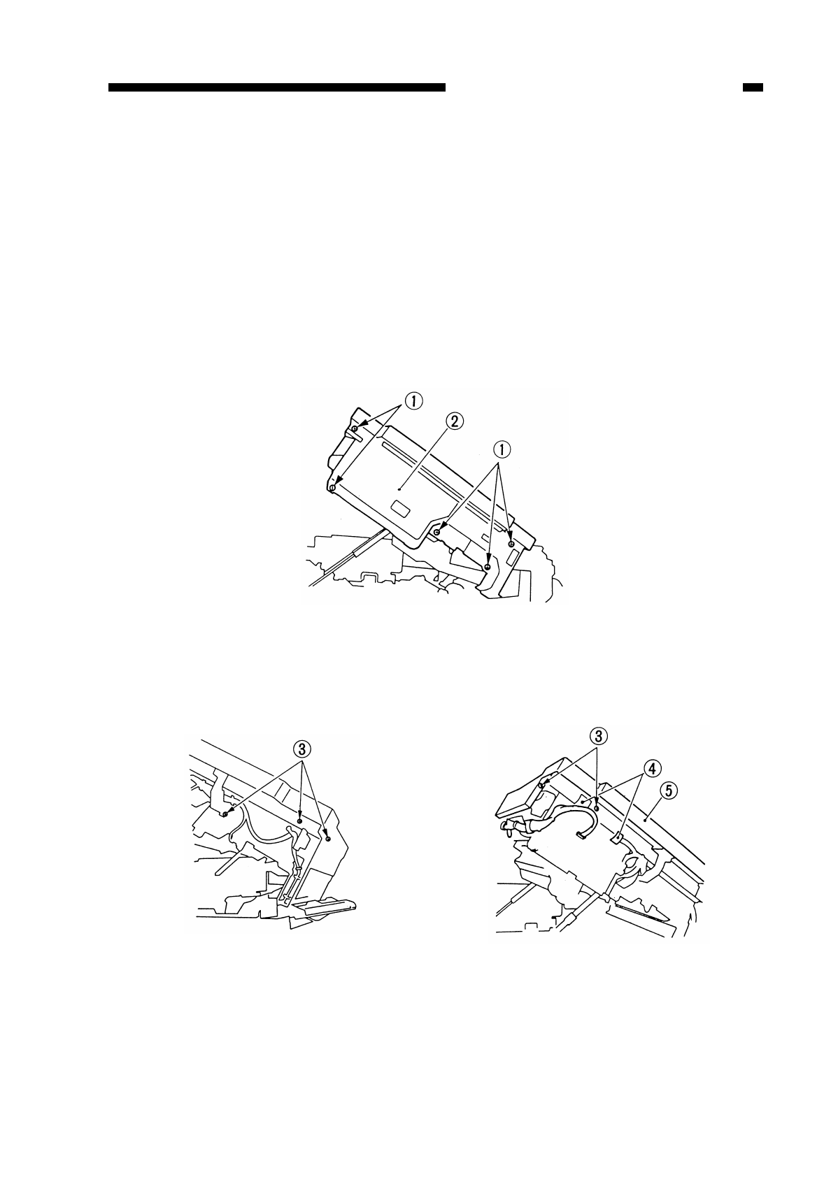
B. Control Panel
1. Detaching the Control Panel
1) Detach the copyboard glass.
2) Detach the upper left cover.
3) Open the front door.
4) Pull the copier’s open/close lever to open the copier.
5) Detach the upper rear cover.
6) Detach the right cover.
7) Detach the left cover.
8) Remove the five screws q, and detach the inside cover w.
Figure 7-205
9) Disconnect the two connectors r(J309, J310) on the DC controller PCB; then,
detach the control panel t.
Figure 7-206 Figure 7-207
COPYRIGHT
©
1997 CANON INC. CANON NP6218 REV. 0 MAY 1997 PRINTED IN JAPAN (IMPRIME AU JAPON)
7-9
CHAPTER 7 EXTERNALS/AUXILIARY MECHANISMS
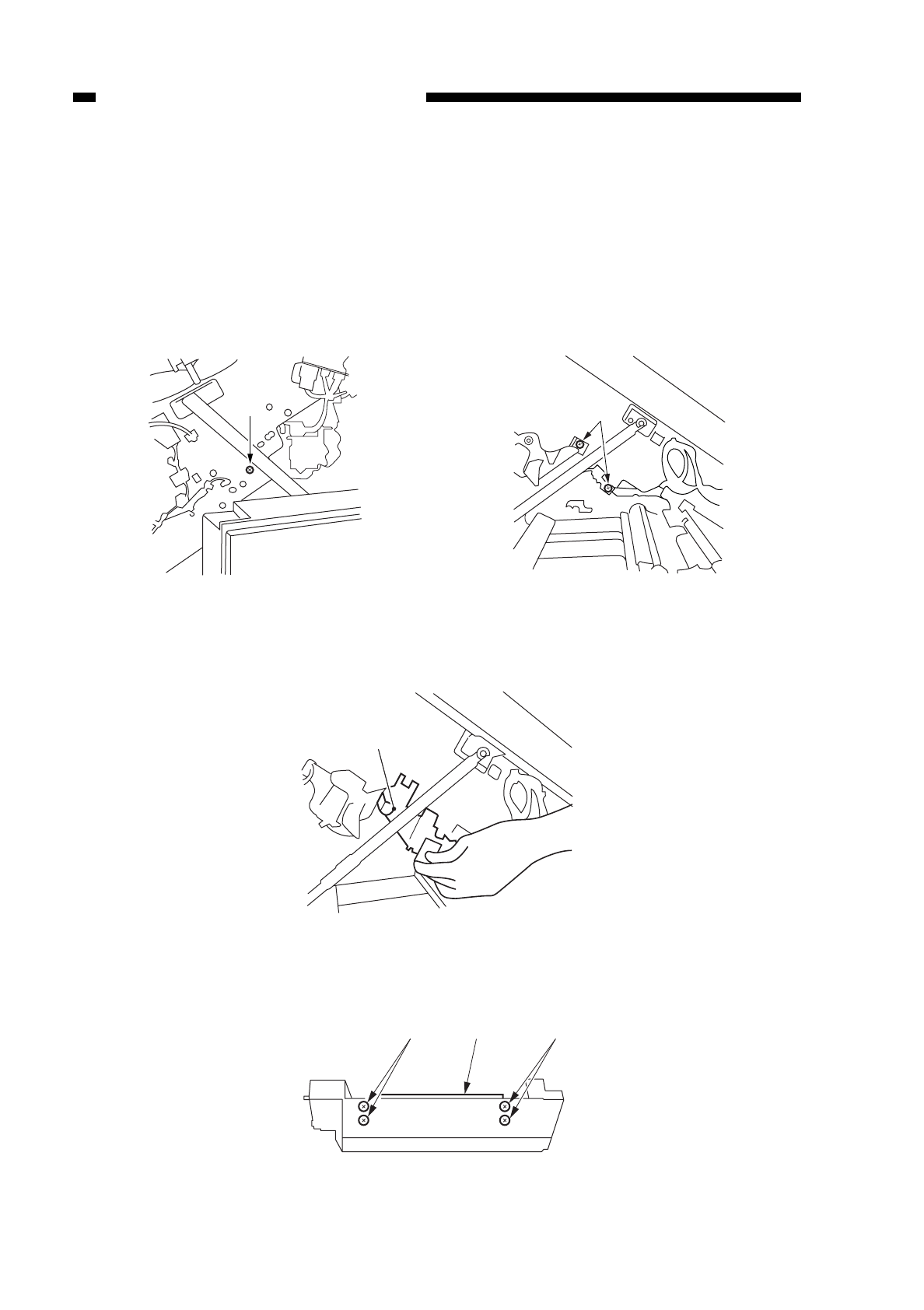
C. Fans
1. Detaching the Exhaust Fan
1) Open the front door.
2) Pull the copier’s open/close lever to open the copier.
3) Detach the DC controller PCB. (See “1. Detaching the DC Controller PCB” on p. 7-17.)
4) Remove the screw qat the copier’s rear, and remove the two screws wat the front.
Figure 7-208 Figure 7-209
5) Pull out the exhaust fan assembly etoward the front while supporting it.
Figure 7-210
6) Remove the four screws r, and detach the exhaust fan t.
Figure 7-211
COPYRIGHT
©
1997 CANON INC. CANON NP6218 REV. 0 MAY 1997 PRINTED IN JAPAN (IMPRIME AU JAPON)
7-10
CHAPTER 7 EXTERNALS/AUXILIARY MECHANISMS
q
w
rrt
e
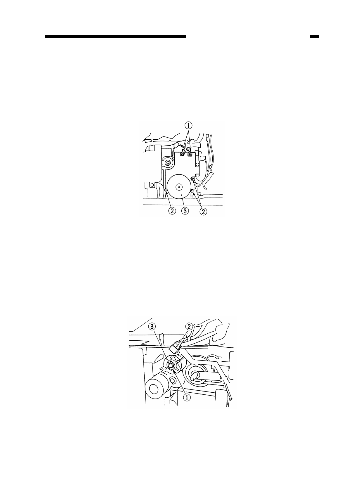
D. Main Motor/Main Drive Assembly
1. Detaching the Main Motor Unit
1) Detach the rear cover.
2) Disconnect the two connectors q, and remove the three screws w; then, detach the
main motor unit e.
Figure 7-212
2. Detaching the Main Drive Assembly
1) Open the front door.
2) Pull out the drum cartridge.
3) Detach the multifeeder unit.
4) Detach the rear cover.
5) Detach the main motor.
6) Remove the clip ring q, and disconnect the connector w; then, detach the
registration clutch e.
Figure 7-213
COPYRIGHT
©
1997 CANON INC. CANON NP6218 REV. 0 MAY 1997 PRINTED IN JAPAN (IMPRIME AU JAPON)
7-11
CHAPTER 7 EXTERNALS/AUXILIARY MECHANISMS
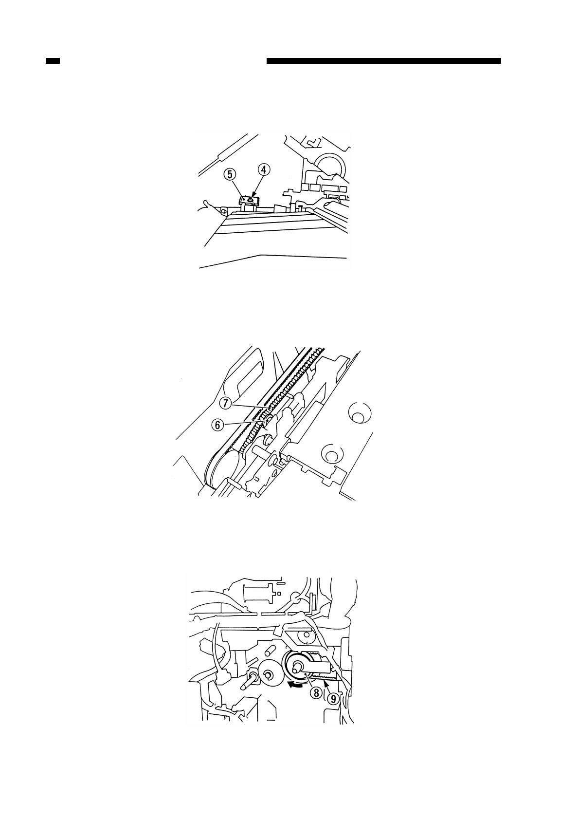
7) Remove the screw r, and detach the composite power supply support plate t.
Figure 7-214
8) Detach the belt from the belt tensioner yof the fixing drive assembly.
Figure 7-215
9) Turn the pulley iclockwise, and detach the belt o.
Figure 7-216
COPYRIGHT
©
1997 CANON INC. CANON NP6218 REV. 0 MAY 1997 PRINTED IN JAPAN (IMPRIME AU JAPON)
7-12
CHAPTER 7 EXTERNALS/AUXILIARY MECHANISMS
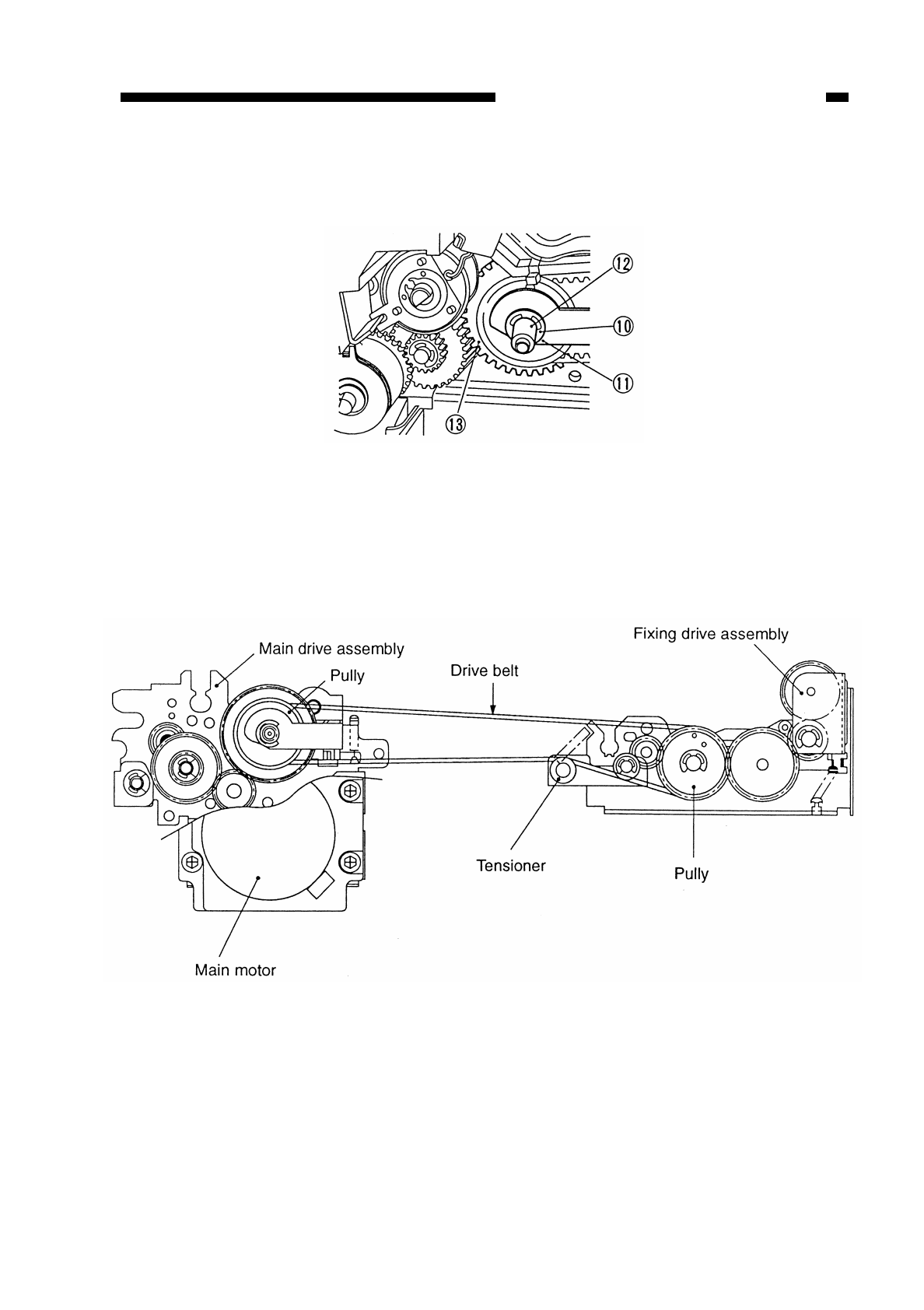
COPYRIGHT
©
1997 CANON INC. CANON NP6218 REV. 0 MAY 1997 PRINTED IN JAPAN (IMPRIME AU JAPON)
7-13
CHAPTER 7 EXTERNALS/AUXILIARY MECHANISMS
10) Remove the E-ring !0 and clip ring !1; then, detach the bushing !2. In this condition,
detach the gear and pulley !3 from the main drive assembly.
Figure 7-217
3. Routing the Drive Belt
Route the drive belt attaching them to the pulley and the tensioner as shown in
Figure 4-218.
Figure 7-218
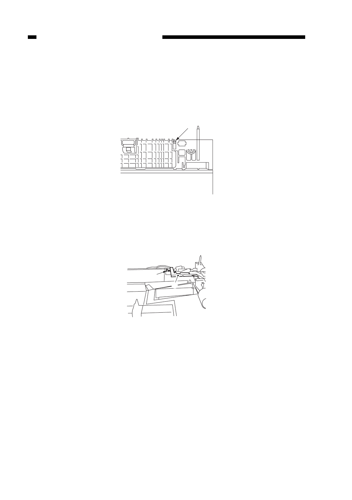
E. Cassette unit
1. Detaching the Pick-Up Drive Unit
1) Detach the rear cover and right cover.
2) Remove the screw q.
Figure 7-219
3) Remove the screw w, and detach the harness guide e.
Figure 7-220
COPYRIGHT
©
1997 CANON INC. CANON NP6218 REV. 0 MAY 1997 PRINTED IN JAPAN (IMPRIME AU JAPON)
7-14
CHAPTER 7 EXTERNALS/AUXILIARY MECHANISMS
q
w
e
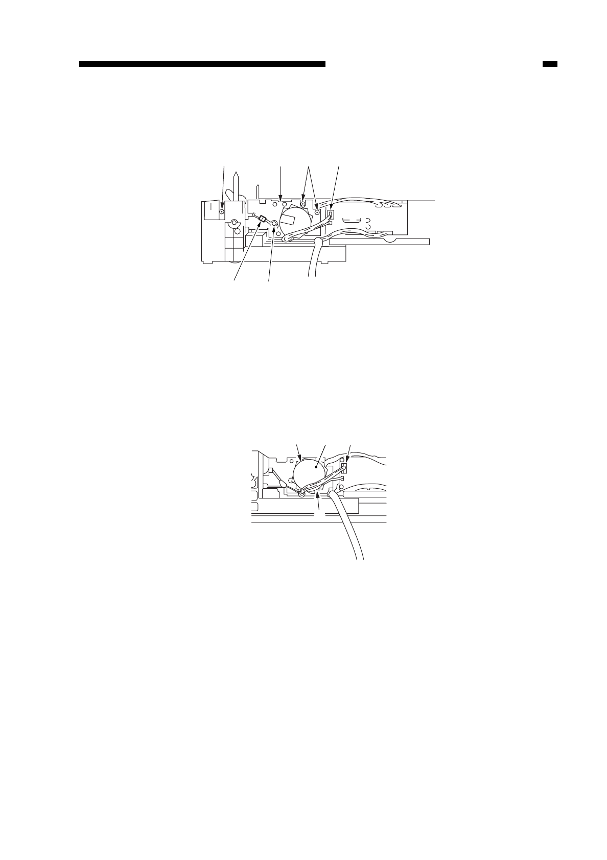
4) Remove the four screws r, and disconnect the two connectors t; then, detach the
pick-up drive unit y.
Figure 7-221
2. Detaching the Cassette Motor
1) Detach the rear cover.
2) Remove the two screws q, and disconnect the connector w(J114); then, detach the
motor e.
Figure 7-222
COPYRIGHT
©
1997 CANON INC. CANON NP6218 REV. 0 MAY 1997 PRINTED IN JAPAN (IMPRIME AU JAPON)
7-15
CHAPTER 7 EXTERNALS/AUXILIARY MECHANISMS
y
rr
r
t
t
e
qw
q
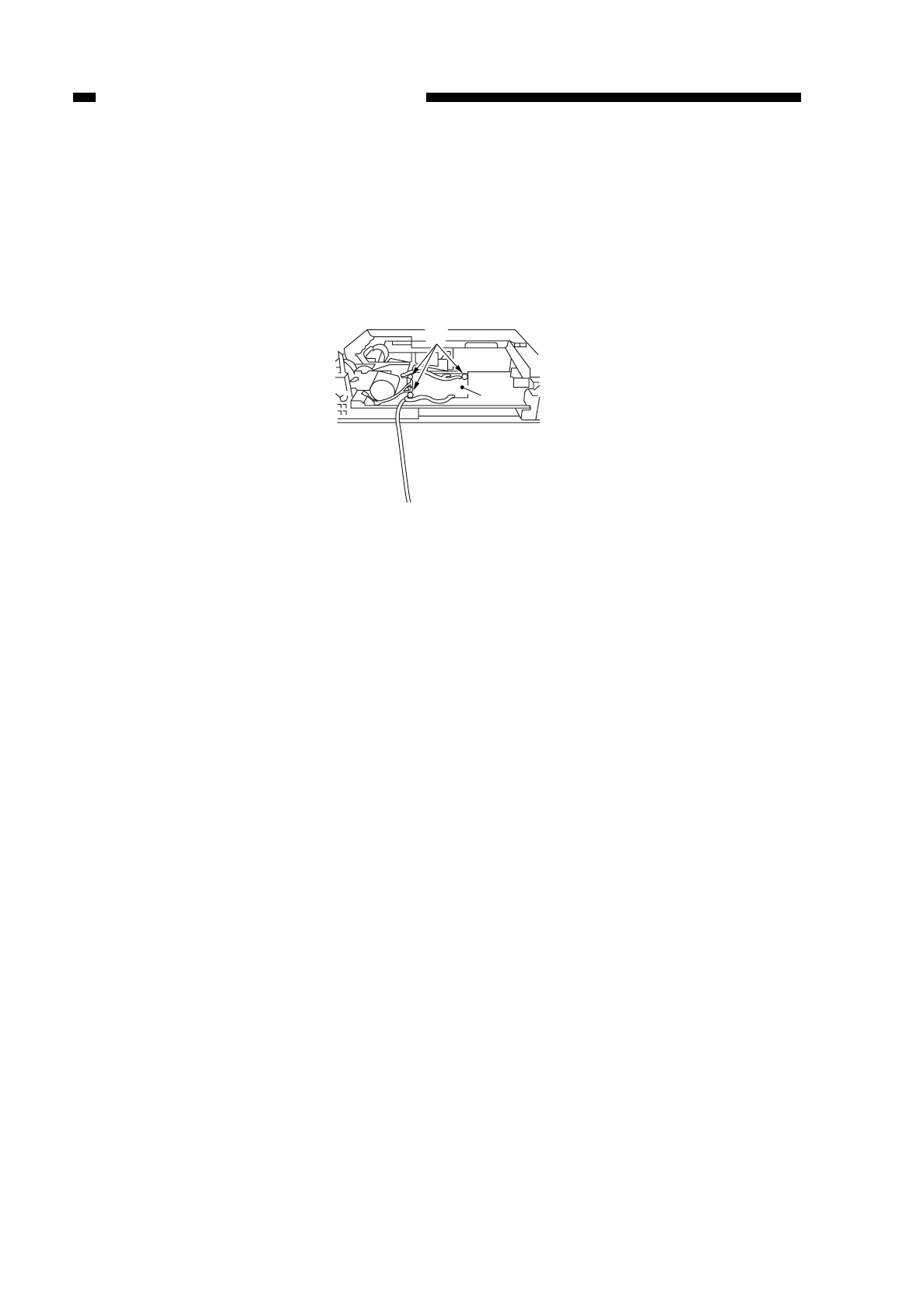
3. Detaching the Cassette Driver PCB
1) Detach the rear cover.
2) Disconnect all connectors from the cassette driver PCB q.
3) Remove the three screws w, and detach the driver PCB q.
Figure 7-223
COPYRIGHT
©
1997 CANON INC. CANON NP6218 REV. 0 MAY 1997 PRINTED IN JAPAN (IMPRIME AU JAPON)
7-16
CHAPTER 7 EXTERNALS/AUXILIARY MECHANISMS
q
w
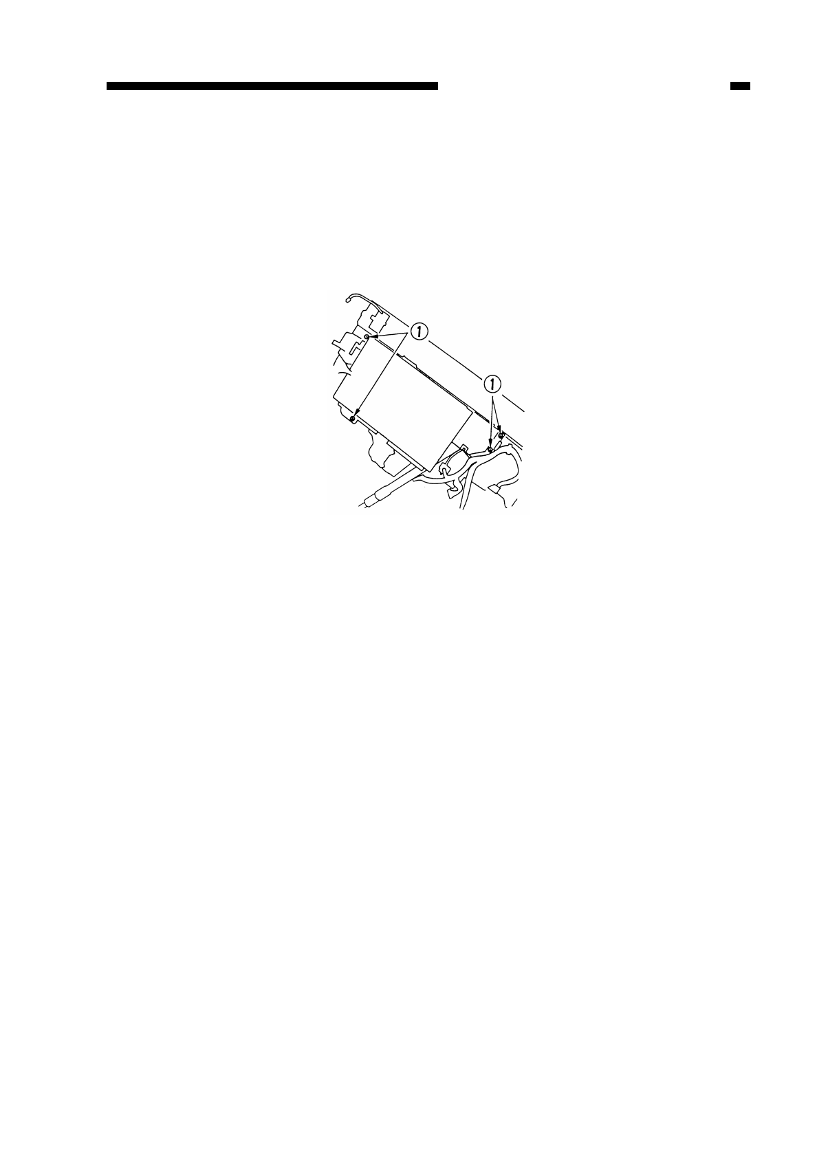
COPYRIGHT
©
1997 CANON INC. CANON NP6218 REV. 0 MAY 1997 PRINTED IN JAPAN (IMPRIME AU JAPON)
7-17
CHAPTER 7 EXTERNALS/AUXILIARY MECHANISMS
F. DC Controller PCB
1. Detaching the DC Controller PCB
1) Disconnect the connector of the DC controller.
2) Remove the four screws q, and detach the DC controller PCB together with its
mount.
Figure 7-224
2. Points to Note When Replacing the DC Controller PCB
• When sending the DC controller PCB to the workshop or factory, put it in a conducting
bag while keeping it intact with the mount. Use a conducting bag whose one side is
transparent, and make sure that the face of the DC controller PCB shows through the
transparent side of the bag.
• After replacement, perform following; see p. 7-20:
qenter the value recorded on the service label;
wadjust the multifeeder paper width sensor;
eadjust the intensioy of the scanning lamp; and
radjust AE.
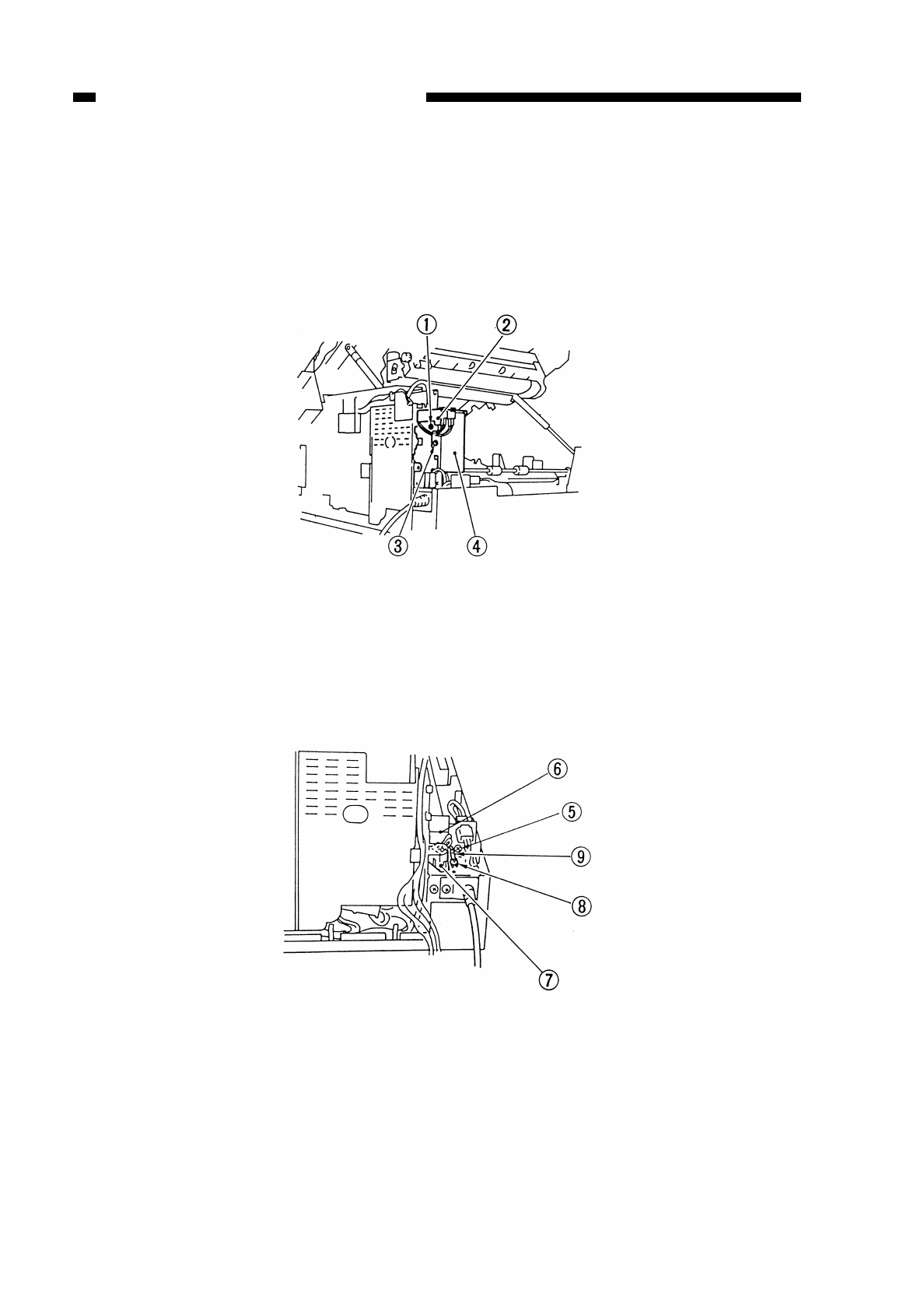
G. Composite Power Supply PCB
1. Detaching the Composite Power Supply PCB
1) Detach the lower rear cover and the delivery cover.
2) Remove the screw q, and detach the switch support plate w.
3) Remove the screw e, and detach the power cord cover 1 r.
Figure 7-225
4) Remove the screw t, and shift the power cord cover 2 y.
5) Disconnect the AC connector u, and remove the screw ito detach the grounding
wire o.
Figure 7-226
COPYRIGHT
©
1997 CANON INC. CANON NP6218 REV. 0 MAY 1997 PRINTED IN JAPAN (IMPRIME AU JAPON)
7-18
CHAPTER 7 EXTERNALS/AUXILIARY MECHANISMS
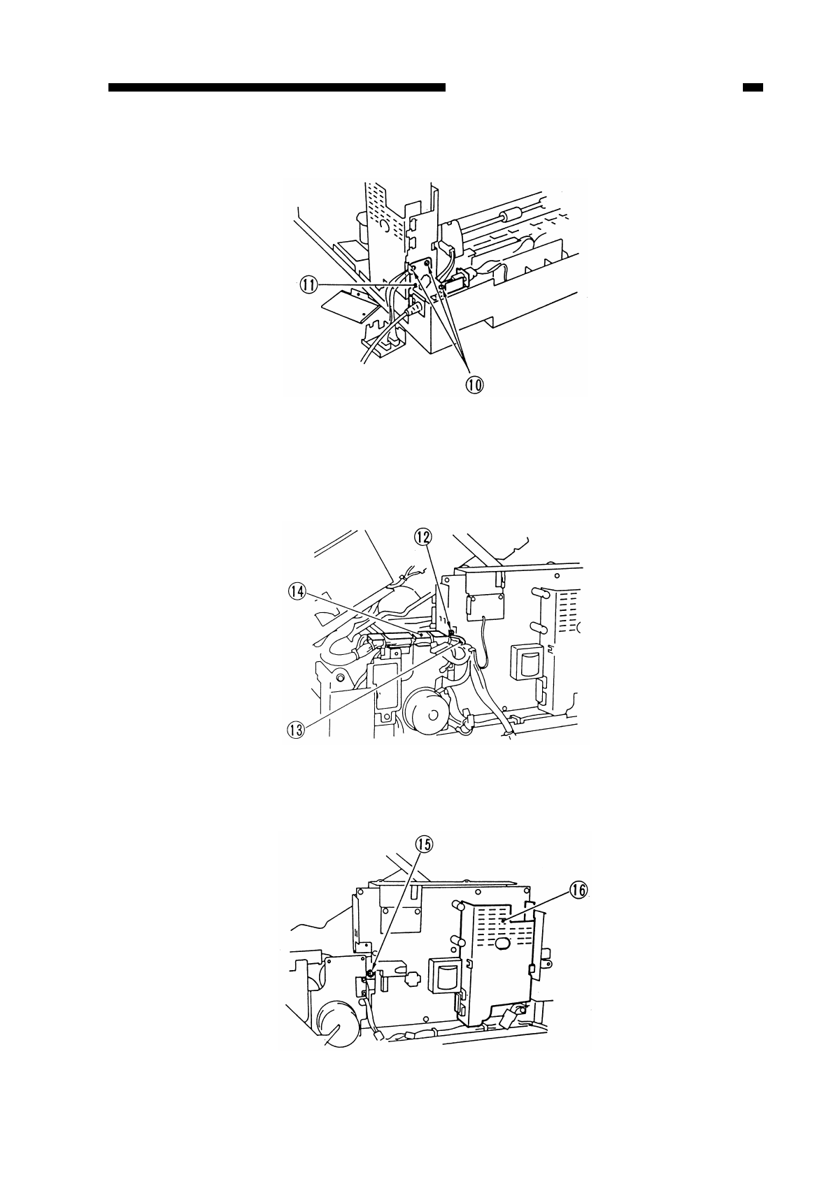
COPYRIGHT
©
1997 CANON INC. CANON NP6218 REV. 0 MAY 1997 PRINTED IN JAPAN (IMPRIME AU JAPON)
7-19
CHAPTER 7 EXTERNALS/AUXILIARY MECHANISMS
6) Remove the three screws !0, and detach the power cord mount !1.
Figure 7-227
7) Disconnect all connectors from the composite power supply PCB.
8) Remove the screw !2, and detach the grounding wire !3; then, detach the harness
guide !4 from the power supply side plate.
Figure 7-228
9) Remove the screw !5, and detach the composite power supply PCB !6.
Figure 7-229

COPYRIGHT
©
1997 CANON INC. CANON NP6218 REV. 0 MAY 1997 PRINTED IN JAPAN (IMPRIME AU JAPON)
7-20
CHAPTER 7 EXTERNALS/AUXILIARY MECHANISMS
2. Points to Note When Handling the Composite Power Supply PCB
• Some capacitors used on the PCB may retain charges even when the copier remains
off. For this reason, you must take care never to short the terminals of the capacitor
whenever you have detached the PCB.
• Enter the settings (Nos. 315 through 318) recorded on the label attached to the
composite power supply (service part) in service mode. (See p. 10-103)

H. AE Sensor PCB
1. Points to Note When Replacing the AE Sensor
• After replacement, perform the following; see p. 10-11:
qAdjust AE.
I. Intensity Sensor PCB
1. Points to Note When Replacing the Intensity Sensor
• After replacement, perform the following; see p. 10-11:
qAdjust the intensity of the scanning lamp; and
wAdjust AE.
COPYRIGHT
©
1997 CANON INC. CANON NP6218 REV. 0 MAY 1997 PRINTED IN JAPAN (IMPRIME AU JAPON)
7-21
CHAPTER 7 EXTERNALS/AUXILIARY MECHANISMS

COPYRIGHT
©
1997 CANON INC. CANON NP6218 REV. 0 MAR. 1997 PRINTED IN JAPAN (IMPRIME AU JAPON)
7-22
CHAPTER 7 EXTERNALS/AUXILIARY MECHANISMS

CHAPTER 8
INSTALLATION
I. SELECTING THE SITE......................8-1
II. UNPACKING AND INSTALLING
THE COPIER......................................8-2
A. Unpacking and Removing
Fixings ...........................................8-2
B. Turning On the Copier ...................8-5
C. Checking the Images and
Operations.....................................8-8
D. Attaching the Drum Unit ................8-9
E. Changing the Cassette Size..........8-10
III. RELOCATING THE COPIER..............8-13
IV. REPLACING THE DRUM UNIT .........8-14
V. INSTALLING THE CONTROL CARD
IV N.....................................................8-17
VI. CASSETTE HEATER KIT 5
INSTALLATION PROCEDURE...........8-19
A. Unpacking......................................8-19
B. Installation (to a Cassette
Feeding Module-A2/B2).................8-20
VII. INSTALLING THE REMOTE
DIAGNOSTIC DEVICE II....................8-26
A. Unpacking......................................8-26
B. Installation to the Copier ...............8-27
This chapter introduces requirements for the site of installation, and shows how the copier may be
installed using step-by-step instructions.
COPYRIGHT
©
1997 CANON INC. CANON NP6218 REV. 0 MAY 1997 PRINTED IN JAPAN (IMPRIME AU JAPON)
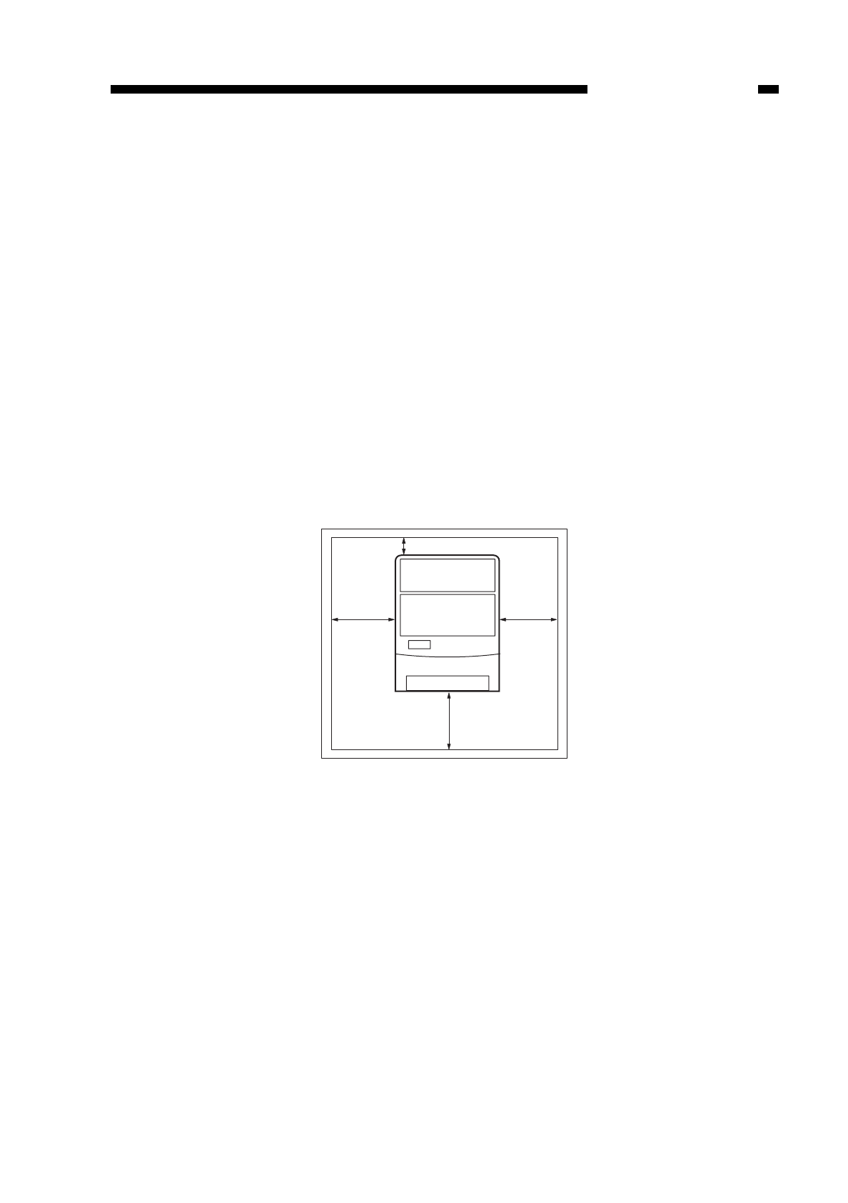
CHAPTER 8 INSTALLATION
COPYRIGHT
©
1997 CANON INC. CANON NP6218 REV. 0 MAY 1997 PRINTED IN JAPAN (IMPRIME AU JAPON)
8-1
I. SELECTING THE SITE
Keep the following in mind when selecting the site of installation; if possible, pay a
visit to the user’s before the delivery of the machine.
1. The site must provide a power outlet that may be used exclusively for the machine
and that meets the rating ±10%.
2. The site must be 7.5°C/45.5°F to 30°C/86.0°F in temperature and 10% RH to 80%
RH in humidity. In particular, avoid areas near water faucets, boilers, humidifiers, or
refrigerators.
3. Avoid areas near sources of fire, areas subject to dust or ammonium gas, or areas
exposed to the direct rays of the sun; if necessary, provide curtains to shut out the
sun.
4. The site must be well ventilated.
5. Make sure that the floor will remain in contact with the copier’s feet and will keep the
copier level.
6. Make sure that there will be work space that meets the measurements shown in
Figure 8-101; in other words, there must be distances A and B around the copier
when measured with its front door open.
Figure 8-101
B
AA
A
A: 50cm/
B: 10cm/19.7in
3.9in
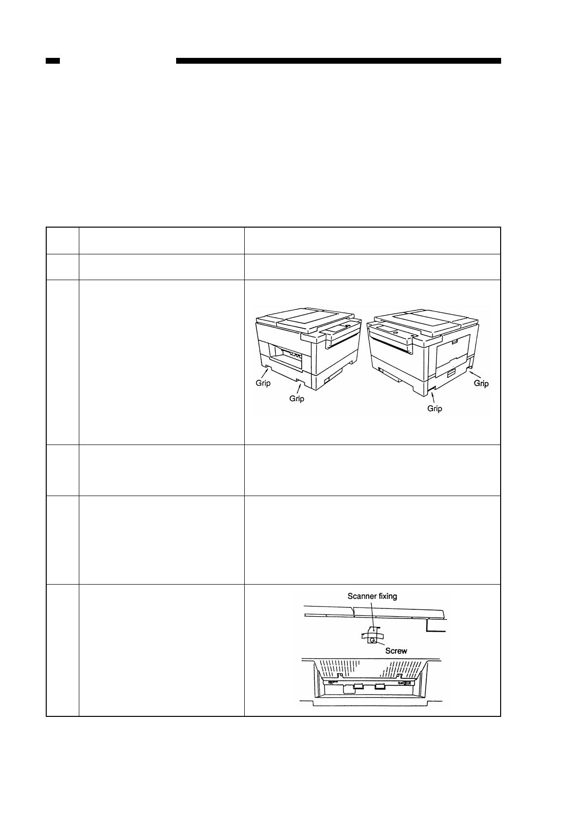
II. UNPACKING AND INSTALLING THE COPIER
When a metal part is brought in from a cold to warm environment, droplets of water
can develop on the surface of the part. This phenomenon is called condensation, and
condensation in a copier can lead to faulty images. If the copier has been moved from a
cold to warm place, leave it alone for about one hour or more before unpacking it.
A. Unpacking and Removing Fixings
Work
Unpack the copier.
Detach the plastic cover, and
place the copier on the
pedestal holding its grips; be
sure to work in a group of two.
Install the Cassette Feeding
Module-B2 or -A2 (accessory)
according to its Installation
Procedure if the copier is to be
placed on it.
Open the cardboard box, and
take out all the accessories.
Remove all tape from the
outside of the copier. Take out
the cassette from the cardboard
box, and remove the cushions
from inside the cassette; then,
slide the cassette into the copier.
Remove the tape from the
scanner fixing found on the
outside of the left cover,
remove the screw, and slide the
fixing to the right to detach it to
the front.
• Keep the fixing stored for
possible relocation of the
machine.
Remarks
Check that none of the following accessories is missing:
•
Copy tray
•
Installation Procedure
•
Cassette (Universal)
•
Operator’s Manual
Make sure that the paper size plate and size label
(1 pc. each) is inside the cassette.
Step
1
2
3
4
5
COPYRIGHT
©
1997 CANON INC. CANON NP6218 REV. 0 MAY 1997 PRINTED IN JAPAN (IMPRIME AU JAPON)
8-2
CHAPTER 8 INSTALLATION
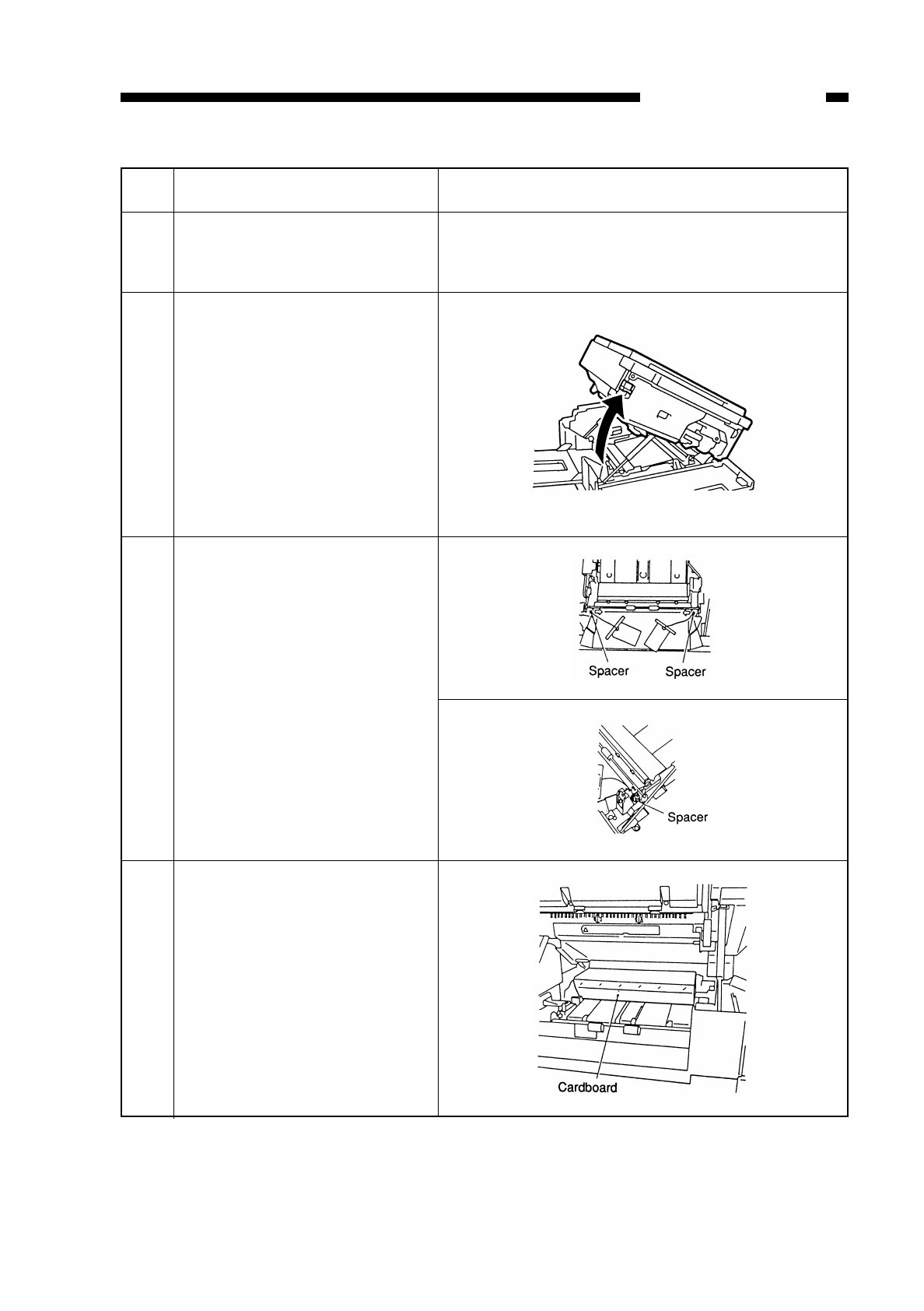
COPYRIGHT
©
1997 CANON INC. CANON NP6218 REV. 0 MAY 1997 PRINTED IN JAPAN (IMPRIME AU JAPON)
8-3
CHAPTER 8 INSTALLATION
Work
Open the copyboard cover,
and remove the protective
sheet.
Open the front cover, and push
the lever found on the left side
up in the direction of the arrow
to open the copier’s top body.
Pull up the spacer (front and
rear, 1 pc. each) of the fixing
roller in the direction of the
arrow until a click is heard.
Remove the two pieces of
cardboard (cushion) from the
feeding assembly.
RemarksStep
6
7
8
9
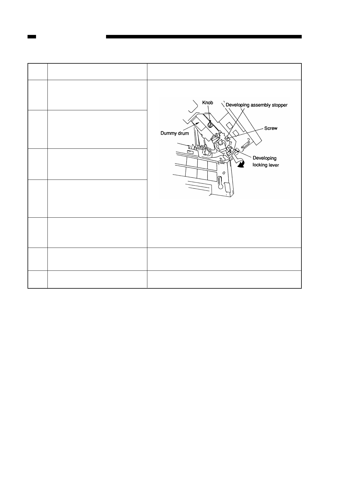
COPYRIGHT
©
1997 CANON INC. CANON NP6218 REV. 0 MAY 1997 PRINTED IN JAPAN (IMPRIME AU JAPON)
8-4
CHAPTER 8 INSTALLATION
Work
Pull the developing locking
lever toward the front, and turn
it clockwise to release it.
Remove the knob, and remove
the dummy drum from the
copier. (Keep the knob for
later.)
Remove the screw, and
remove the developing
assembly stopper.
Remove the developing
assembly, and check that the
developing cylinder is free of
scratches or dirt.
Install the developing assem-
bly, and attach the developing
assembly stopper with a screw.
Engage the developing
assembly.
Close the copier’s top unit.
RemarksStep
10
11
12
13
14
15
16

B. Turning On the Copier
Step
1
2
3
4
5
6
7
8
CHAPTER 8 INSTALLATION
COPYRIGHT
©
1997 CANON INC. CANON NP6218 REV. 0 MAY 1997 PRINTED IN JAPAN (IMPRIME AU JAPON)
8-5
Work
Connect the power plug to the
power outlet.
Turn on the power switch.
Turn off the power switch.
Supply toner according to the
instructions given on the toner
supply label attached behind
the front door.
Release the developing
assembly by the developing
assembly locking lever.
Install the drum unit.
Lock the developing assembly,
and close the copier’s top unit.
Insert the door switch activator
into the door switch, and turn
on the power.
Remarks
• Make sure that the power outlet is the rating
±10%.
Make sure that the Add Paper message flashes.
• Press the keypad and the Clear key to make
sure that the copy count indication is correct.
When turning the toner cartridge counterclock-
wise to set it, you must fully turn it until it is
locked; the developing assembly can cause a
fault if you operate the machine without locking
the cartridge.
See “D. Attaching the Drum Unit.”
Caution:
Caution:
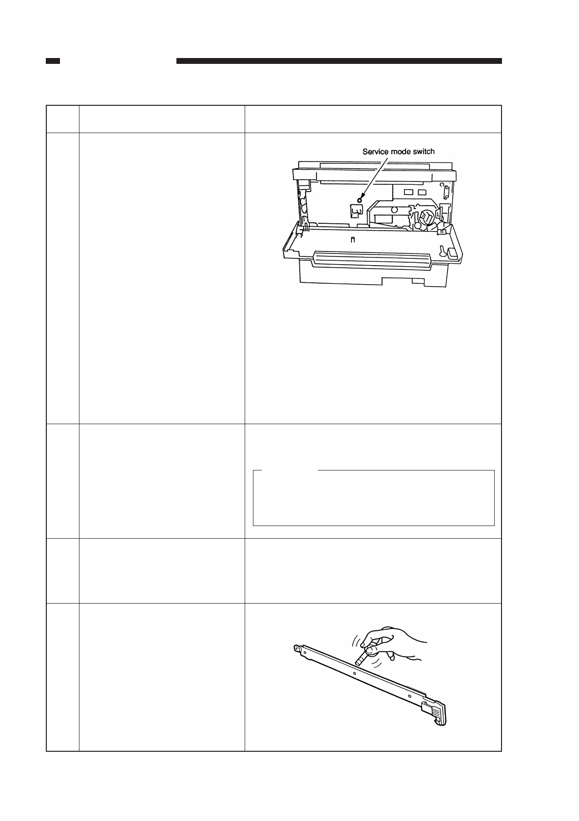
COPYRIGHT
©
1997 CANON INC. CANON NP6218 REV. 0 MAY 1997 PRINTED IN JAPAN (IMPRIME AU JAPON)
8-6
CHAPTER 8 INSTALLATION
Work
Select service mode No.
313/314, and enter the settings
recorded on the drum label.
To select service mode,
• Press the service mode
switch (SW302) with a hex
key.
Select ‘3’ of the mode by
pressing ‘3’ on the keypad
and AE key; then, select ‘No.
3 xx’ by pressing ‘x’ and ‘x’
on the keypad and the start
key.
Execute ‘No. 401’ in service
mode.
• Press the service mode
switch (SW302), ‘4’ on the
keypad, AE Key, and Start
key in sequence.
Make sure that step 10 has
been completed; then, turn off
the power, and open the
copier’s top unit.
Remove the static eliminator,
and clean it with the static
eliminator brush; then, set the
static eliminator.
Remarks
To enter settings,
• Select ‘No. 313’ in service mode, and enter the
setting recorded on the label (PRIMARY) using
the keypad. (To enter ‘-’, press the % key before
entering the setting.)
Then, press the Start key to store the setting.
To enter the setting for IP_OFST, select ‘No. 314’
in service mode and work in the same way.
The copier supplies toner from the toner container
to the developing assembly (about 5 min).
• Do not turn off the power or remove the door
switch actuator while the machine is operat-
ing.
Step
9
10
11
12
Caution:

COPYRIGHT
©
1997 CANON INC. CANON NP6218 REV. 0 MAY 1997 PRINTED IN JAPAN (IMPRIME AU JAPON)
8-7
CHAPTER 8 INSTALLATION
Remarks
The copier automatically sets the APVC value; it
stops in about 23 sec.
See “E. Changing the Size.”
• Make sure that the Add Paper message turns off.
• Make sure that the paper indicator matches with
the APVC value; it stops in about 23 sec.
size of the cassette.
• Press the keys on the control panel other than
the Copy Start key to make sure that all
respective operations are normal.
Step
13
14
15
16
17
18
19
Work
Turn on the power.
Execute ‘No. 412’ in service
mode.
• Press the service mode
swicth (SW302), ‘4’ on the
keypad, AE key, ‘1’ and ‘2’ on
the keypad, and Start key in
sequence.
Set the settings for user mode
and settings mode in service
mode to suit the needs of the
user.
Tailor the cassette to suit the
desired size by operating the
size guide plate and size
detecting lever; then, attach
the size label.
Put copy paper in the cassette,
and set the cassette in the
copier.
Attach the copy tray.
Remove the door switch acti-
vator, and close the front door.

C. Checking the Images and Operations
COPYRIGHT
©
1997 CANON INC. CANON NP6218 REV. 0 MAY 1997 PRINTED IN JAPAN (IMPRIME AU JAPON)
8-8
CHAPTER 8 INSTALLATION
Work
Place the Test Sheet on the
copyboard, and check the
copies.
Make copies in manual mode.
Make sure that the external
covers are free from scratches
and deformations.
Clean the area around the
copier.
Move the machine to its site of
installation.
Check/Remarks
• Make sure there is no abnormal sound.
• Check the copy images for each standard
reproduction ratio.
• Make sure that as many copies as specified are
made normally.
• If the copy image is faulty, perform the “Image
Adjustment Basic Procedure.”
Make sure that the copying operation is normal.
Make sure that the copier is more or less level.
Step
1
2
3
4
5
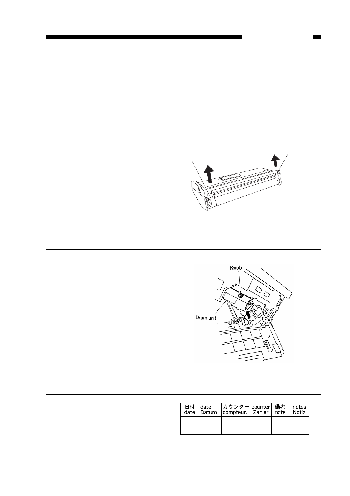
D. Attaching the Drum Unit
COPYRIGHT
©
1997 CANON INC. CANON NP6218 REV. 0 MAY 1997 PRINTED IN JAPAN (IMPRIME AU JAPON)
8-9
CHAPTER 8 INSTALLATION
Work
Unpack the drum unit, and
remove the light-blocking
sheet.
Remove the primary charging
roller releasing spacer.
Set the drum unit to the copier,
and fix it in position using the
knob used to keep the dummy
drum.
Fill out the label, and attach it
to the drum unit cover.
Check/Remarks
Take care not to damage the surface of the drum
and not to touch the primary charging roller.
Be sure to insert the drum unit straight along the
copier’s rail.
Step
1
2
3
4
Releasing spacer
Releasing spacer
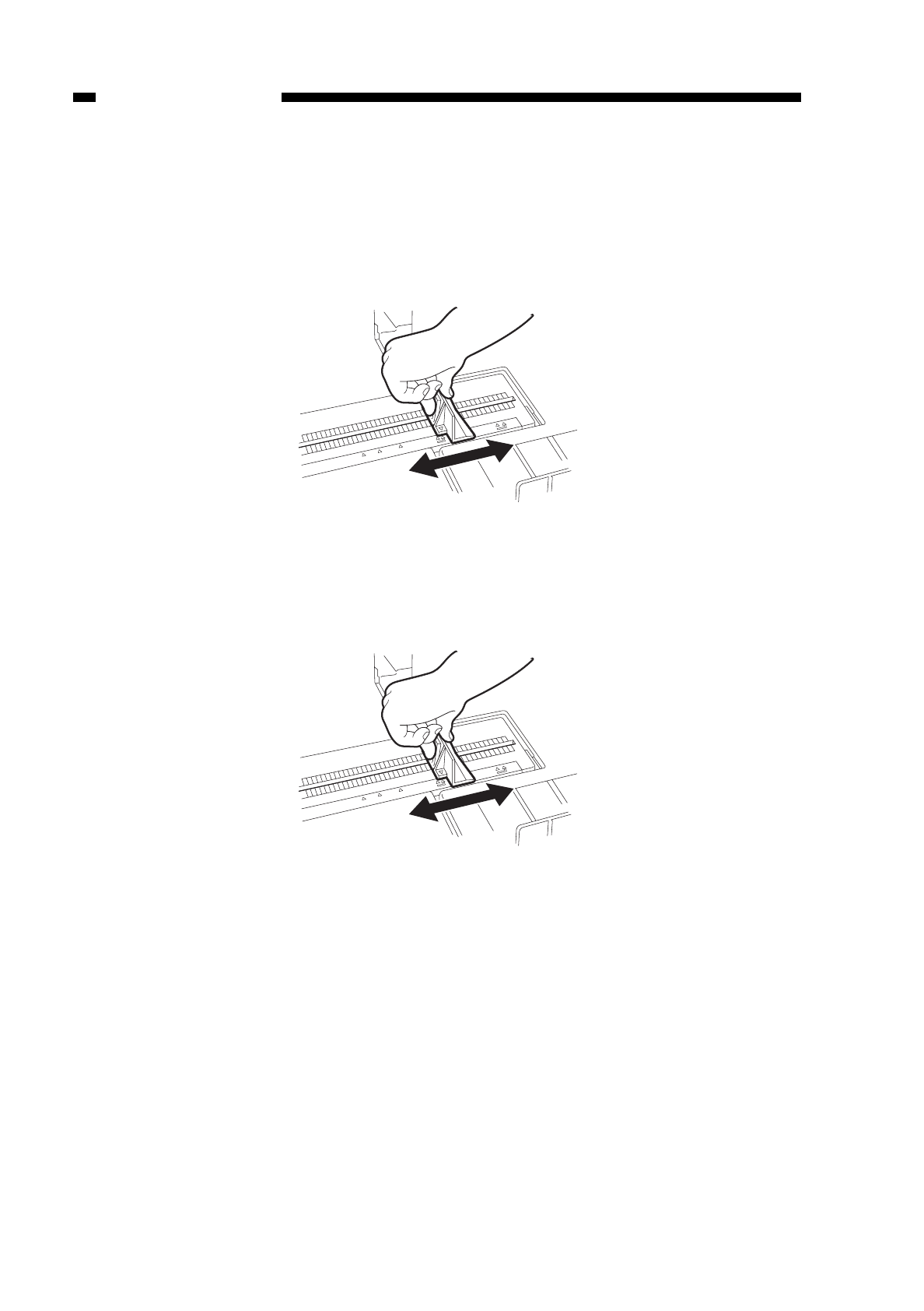
COPYRIGHT
©
1997 CANON INC. CANON NP6218 REV. 0 MAY 1997 PRINTED IN JAPAN (IMPRIME AU JAPON)
8-10
CHAPTER 8 INSTALLATION
E. Changing the Cassette Size
Change the cassette size to suit the user’s needs.
1) Slide the cassette out of the copier.
2) Move the length plate inside the cassette to suit the length of the paper size.
Figure 8-201
3) Move the width plate inside the cassette to suit the width of the paper to be used.
Figure 8-202
A4R LTR R B5R A4/A5R A5
STMT
LTR STMTR
A4R LTR R B5R A4/A5R A5
STMT
LTR STMTR
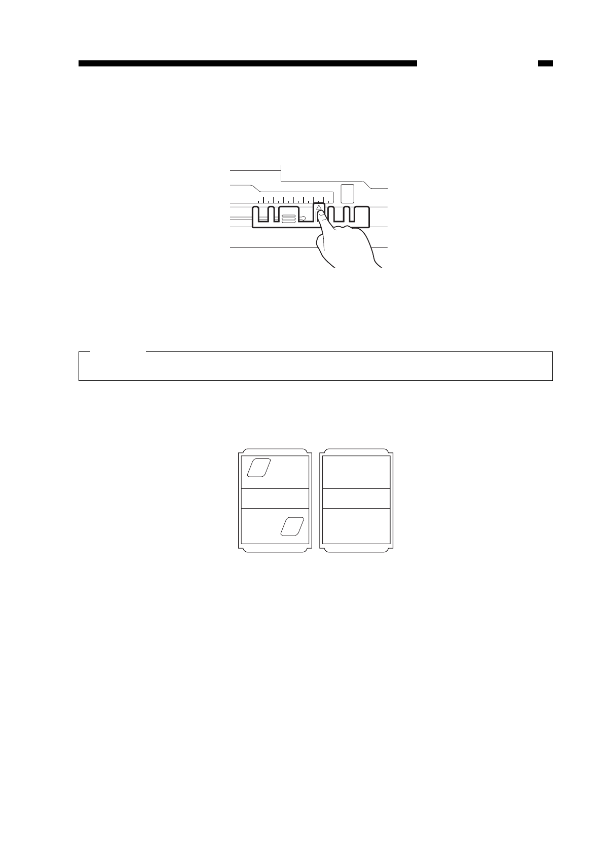
4) Move the paper size lever found toward the front of the cassette so that it is aligned
with the size of the paper to be used.
Figure 8-203
Caution:
Failure to adjust the paper size lever will lead to jams or soiling.
5) Take out the paper size plates for the cassette, and pick out the four plates
representing the most frequently used size; attach the labels.
Figure 8-204
COPYRIGHT
©
1997 CANON INC. CANON NP6218 REV. 0 MAY 1997 PRINTED IN JAPAN (IMPRIME AU JAPON)
8-11
CHAPTER 8 INSTALLATION
A5R B5R A4R A B B A A
U STMTRLTRR STM LGL LTR 11x17
A4
A3
A4
R
A5
R

6) Set the paper size plates selected in step 4).
Figure 8-205
Caution:
If you are setting the plate for the position representing the universal (u) cassette,
you must perform the work described for “universal cassette paper size setting
(505); see p. 10-44.
■Points to Note When Handling the Photosensitive Drum after Installation
The copier’s photosensitive drum is highly susceptible to light; mere exposure to
room light can affect the drum enough to produce white spots or black lines on the
copies. Keep the following in mind:
• Do not spend more than 5 min when removing jams.
• After detaching the drum unit from the copier during servicing work, be sure to
protect it in the light-blocking sheet that came with the drum or fresh copy paper,
and place the drum in a dark place.
Do not touch the photosensitive drum or primary charging roller.
If you have soiled the surface of the drum inadvertently, wipe it using a flannel cloth
coated with toner; do not use paper, lint-free or otherwise.
Do not dry wipe or use solvent to clean the drum.
COPYRIGHT
©
1997 CANON INC. CANON NP6218 REV. 0 MAY 1997 PRINTED IN JAPAN (IMPRIME AU JAPON)
8-12
CHAPTER 8 INSTALLATION
After setting the size plate, make sure it corresponds to the paper size you have selected.

III. RELOCATING THE COPIER
If you must relocate the copier by truck or using other means of transportation,
perform the following work:
COPYRIGHT
©
1997 CANON INC. CANON NP6218 REV. 0 MAY 1997 PRINTED IN JAPAN (IMPRIME AU JAPON)
8-13
CHAPTER 8 INSTALLATION
Work
Move the lens to the Direct
position.
Take out the drum unit.
Fix the scanner in place.
Tape the front door and delivery
assembly in place.
Place A3 copy paper on the
copyboard glass, and tape the
copyboard cover in place.
Checks
Put the drum unit in a
box for transport.
Step
1
2
3
4
5
Remarks
Direct position
refers to
the position of the lens
after warm-up initiated
by power-on.
Use the fixing removed
at time of installation.
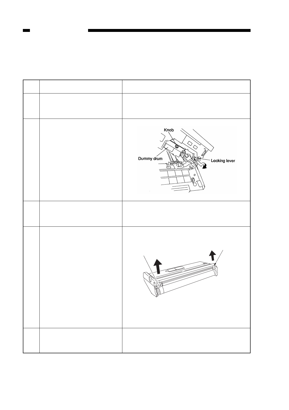
IV. REPLACING THE DRUM UNIT
Go through the following when replacing the drum unit:
COPYRIGHT
©
1997 CANON INC. CANON NP6218 REV. 0 MAY 1997 PRINTED IN JAPAN (IMPRIME AU JAPON)
8-14
CHAPTER 8 INSTALLATION
Work
Turn off the copier, and open
the front door and the copier’s
top unit.
Release the developing
assembly, and remove the
knob to remove the drum unit.
Unpack the new drum unit, and
remove the light-blocking
sheet.
Remove the primary charging
roller releasing spacer.
Set the drum unit to the copier,
and attach the knob used to fix
the old drum unit.
Remarks
Take care not to damage the surface of the drum
and not to touch the primary charging roller.
Step
1
2
3
4
5
Releasing spacer
Releasing spacer
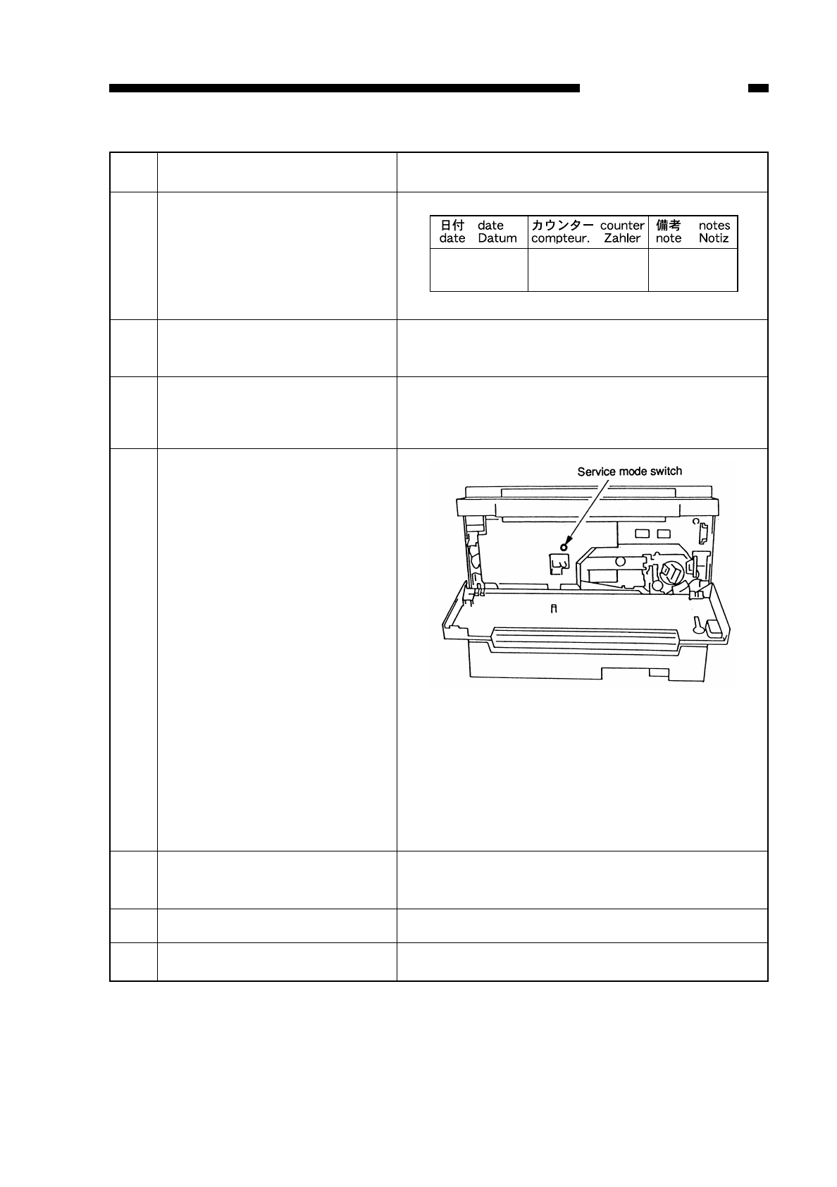
COPYRIGHT
©
1997 CANON INC. CANON NP6218 REV. 0 MAY 1997 PRINTED IN JAPAN (IMPRIME AU JAPON)
8-15
CHAPTER 8 INSTALLATION
Work
Fill out the label, and attach it
to the drum unit cover.
Lock the developing assembly,
and close the copier’s top unit.
Turn on the door switch using
the door switch actuator; then,
shift the power switch to ‘ON’.
Select service mode No.
313/314, and enter the settings
recorded on the drum label.
To select service mode,
• Press the service mode
switch (SW302) with a hex
key.
Select ‘3’ of the mode by
pressing ‘3’ on the keypad
and AE key; then, select ‘No.
3 xx’ by pressing ‘x’ and ‘x’
on the keypad and the start
key.
Turn off the power, and open
the copier’s top unit.
Replace the static eliminator.
Turn on the power.
Remarks
To enter settings,
• Select ‘No. 313’ in service mode, and enter the
setting recorded on the label (PRIMARY) using
the keypad. (To enter ‘-’, press the % key before
entering the setting.)
Then, press the Start key to store the setting.
To enter the setting for IP_OFST, select ‘No. 314’
in service mode and work in the same way.
Step
6
7
8
9
10
11
12

COPYRIGHT
©
1997 CANON INC. CANON NP6218 REV. 0 MAY 1997 PRINTED IN JAPAN (IMPRIME AU JAPON)
8-16
CHAPTER 8 INSTALLATION
Work
Execute ‘No. 412’ in service
mode.
• Press the service mode
swicth (SW302), ‘4’ on the
keypad, AE key, ‘1’ and ‘2’ on
the keypad, and Start key in
sequence.
Remove the door switch actua-
tor, and close the front door.
Remarks
The copier automatically sets the APVC value; it
stops in about 23 sec.
Step
13
14
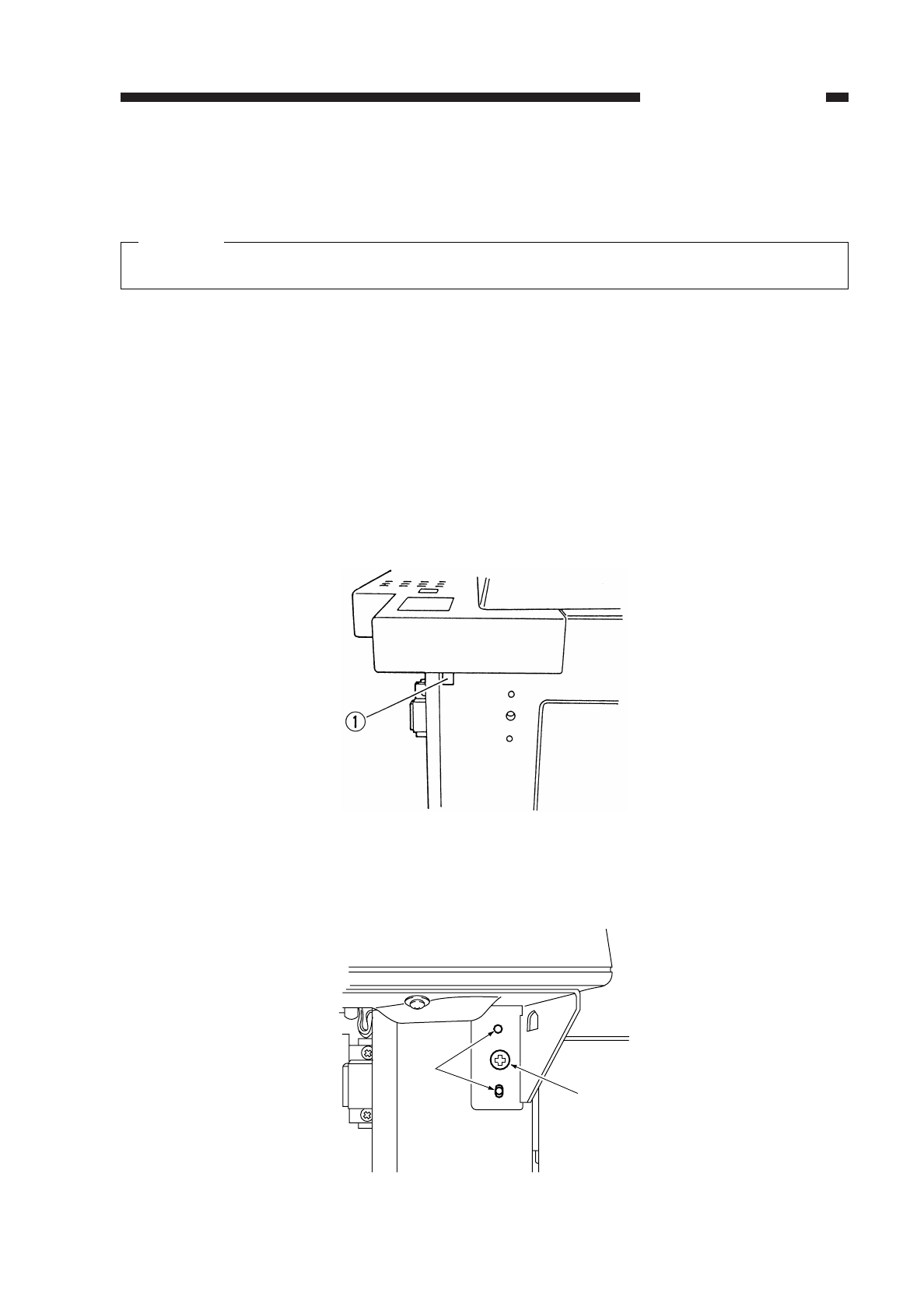
V. INSTALLING THE CONTROL CARD IV N
Caution:
Be sure to disconnect the copier’s power plug before starting the installation work.
1) Open the front cover
2) Open the copier’s top body by operating its open/close lever.
3) Detach the front cover.
4) Take out the cartridge.
5) Detach the inside cover.
6) Loosen the screw on the upper rear cover.
7) Loosen the two screws on the copyboard glass.
8) Detach the face plate qfrom the control card cable inlet.
When detaching the face plate q, detach it in the direction of the arrow using
pliers or screwdriver.
Figure 8-501
9) Fix the Control Card IV N to the copier using a screw w(M4×12); at the time, be use
that the copier’s emboss eis fitted in the hole in the Control Card IV N.
Figure 8-502
COPYRIGHT
©
1997 CANON INC. CANON NP6218 REV. 0 MAY 1997 PRINTED IN JAPAN (IMPRIME AU JAPON)
8-17
CHAPTER 8 INSTALLATION
e
w
()
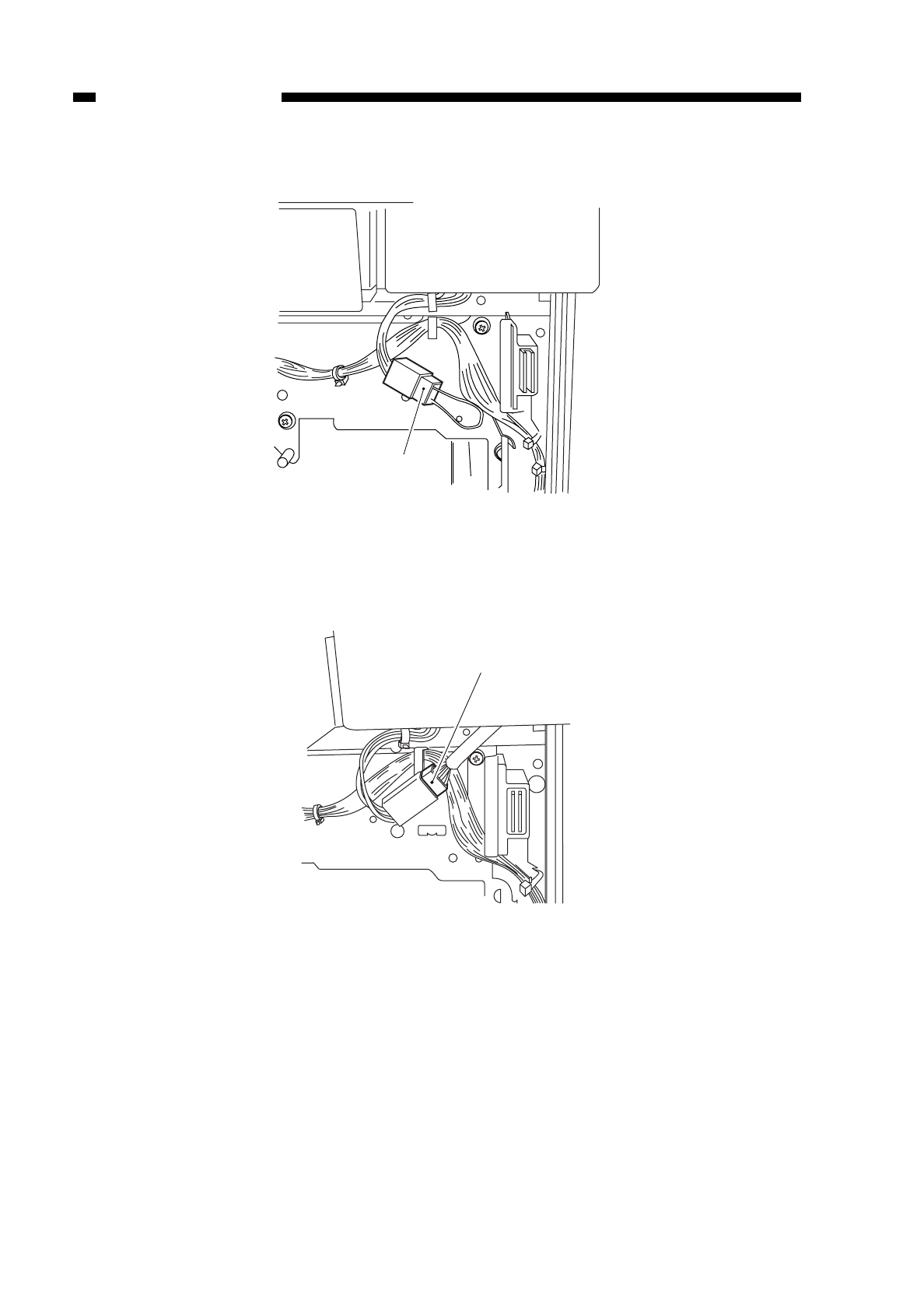
10) Disconnect the copier’s dummy connector r.
Figure 8-503
11) Connect the connector tof the Control Card IV N.
Figure 8-504
12) Connect the copier’s power plug, and turn on its power switch to check the operation
of the Control Card IV N.
COPYRIGHT
©
1997 CANON INC. CANON NP6218 REV. 0 MAY 1997 PRINTED IN JAPAN (IMPRIME AU JAPON)
8-18
CHAPTER 8 INSTALLATION
r
t
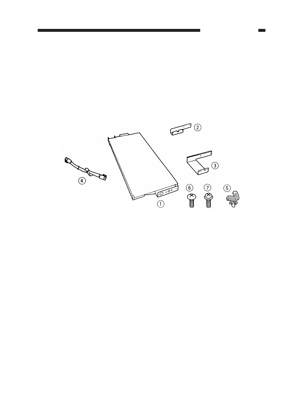
VI.CASSETTE HEATER KIT 5 INSTALLATION PROCE-
DURE
A. Unpacking
Open the shipping box, and check to make sure that none of the parts shown in Fig.
8-601 is missing.
Figure 8-601
qCassette Heater...............................1 tCord clamp ......................................1
wMounting plate 1 ..............................1 yBinding screw (black; M4×6) ...........2
eMounting plate 2 ..............................1 uTP screw (white; M3×6)...................2
rRelay harness..................................1
COPYRIGHT
©
1997 CANON INC. CANON NP6218 REV. 0 MAY 1997 PRINTED IN JAPAN (IMPRIME AU JAPON)
8-19
CHAPTER 8 INSTALLATION
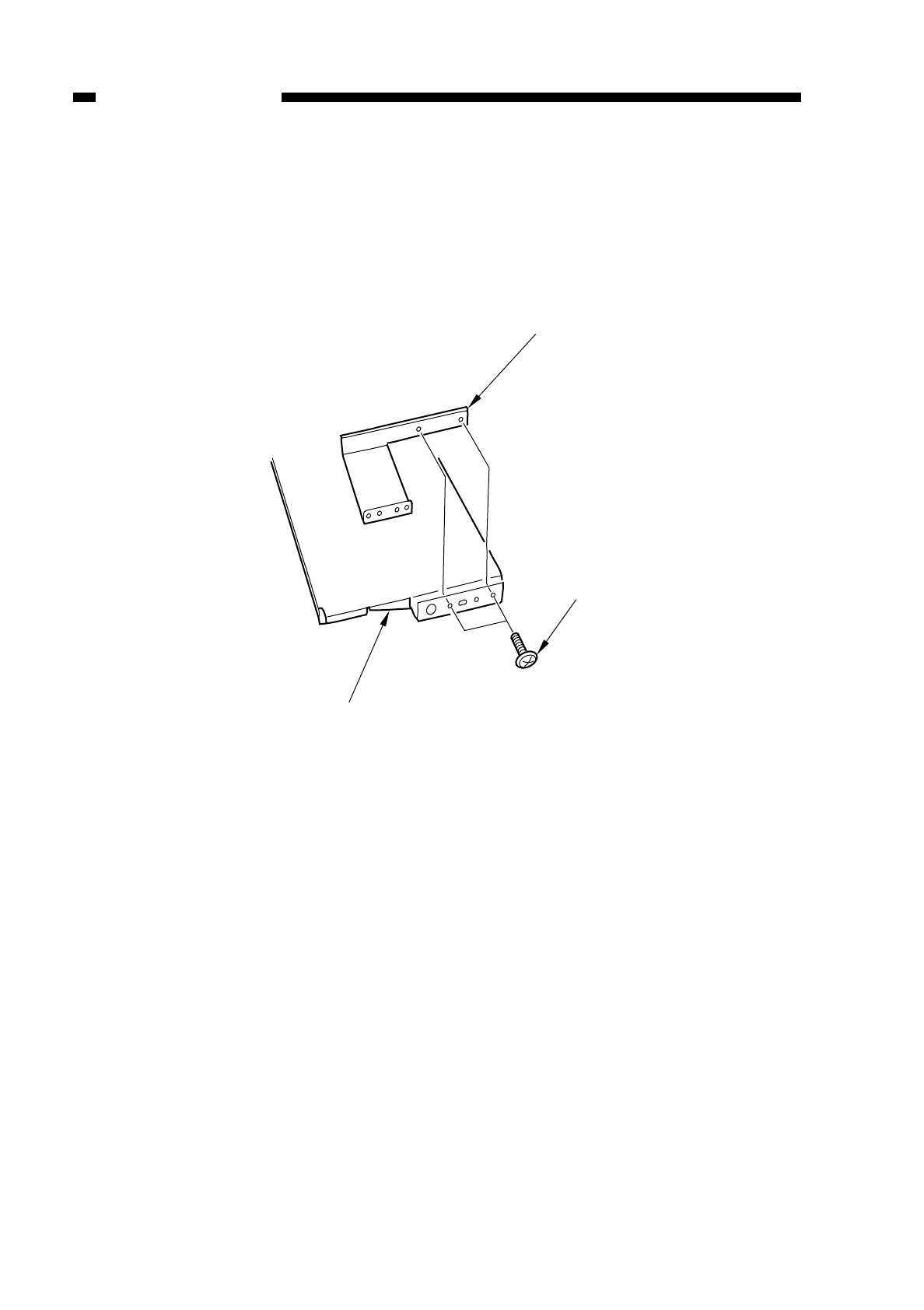
B. Installation (to a Cassette Feeding Module-A2/B2)
1) Remove the cassettes and all rear covers from the cassette feeding unit/pedestal.
2) Remove the copier’s rear cover.
3) Install the mounting plate 2 to the cassette heater with two screws (black; M4×6).
Figure 8-602
COPYRIGHT
©
1997 CANON INC. CANON NP6218 REV. 0 MAY 1997 PRINTED IN JAPAN (IMPRIME AU JAPON)
8-20
CHAPTER 8 INSTALLATION
Cassette heater
Screw
Mounting plate 2
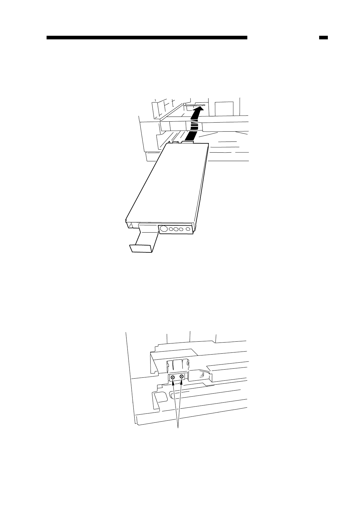
4) Insert the bend found at the rear of the heater into the heater mounting slit in the rear
side plate of the cassette feeding unit/pedestal (bottom holder).
Figure 8-603
5) Open the cover on the front of the cassette feeding unit/module, and fix the mounting
plate 2 in place to the front side plate with two screws (white; M3×6).
Figure 8-604
COPYRIGHT
©
1997 CANON INC. CANON NP6218 REV. 0 MAY 1997 PRINTED IN JAPAN (IMPRIME AU JAPON)
8-21
CHAPTER 8 INSTALLATION
Screws
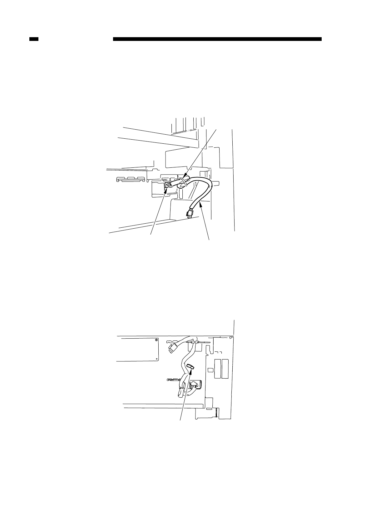
6) Close the cover.
7) Connect the connector on the relay harness to the connector of the cassette heater
(rear side plate of the cassette feeding unit). (Connect the side where the harness
is bundled with a tie-wrap.)
Figure 8-605
8) Install the cord clamp to the hole in the rear side plate of the cassette feeding
unit/pedestal.
• Cassette Feeding Module-A2
Figure 8-606
COPYRIGHT
©
1997 CANON INC. CANON NP6218 REV. 0 MAY 1997 PRINTED IN JAPAN (IMPRIME AU JAPON)
8-22
CHAPTER 8 INSTALLATION
Connector Cord clamp
Tie-wrap
Cord clamp
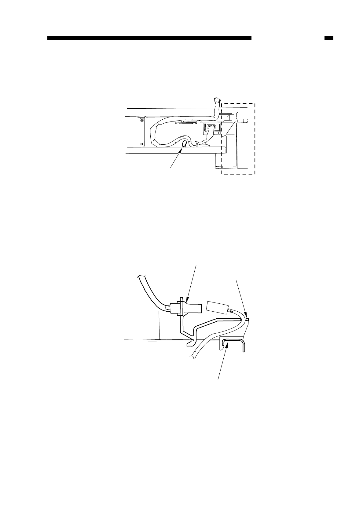
• Cassette Feeding Module-B2
Figure 8-607
9) Lead the other connector on the relay harness through the copier’s bottom plate as
shown.
Figure 8-608
COPYRIGHT
©
1997 CANON INC. CANON NP6218 REV. 0 MAY 1997 PRINTED IN JAPAN (IMPRIME AU JAPON)
8-23
CHAPTER 8 INSTALLATION
Cord clamp
Copier's connector
Molded member
Copier's base plate
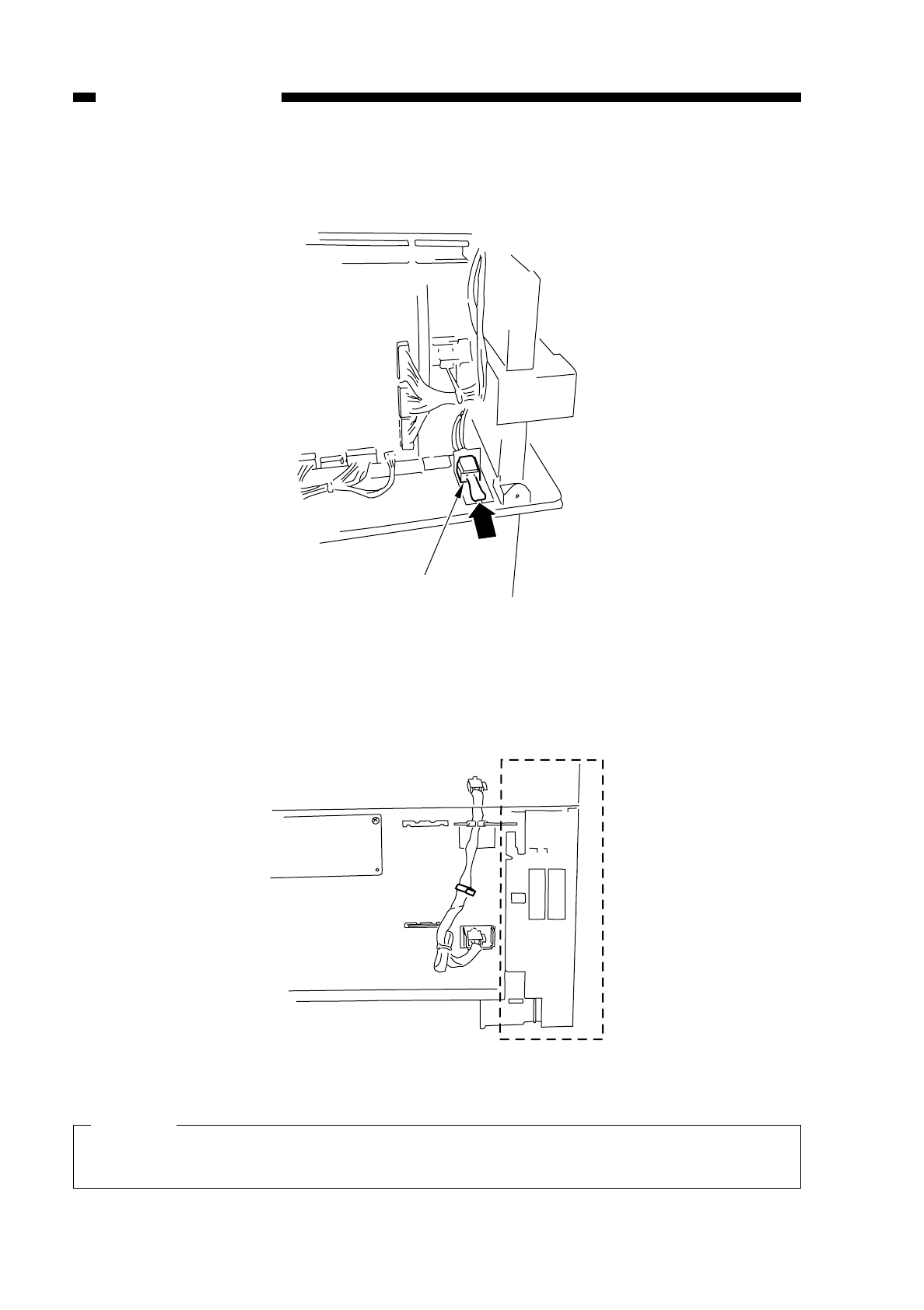
10) Connect the connector on the relay harness with the copier’s connector.
Figure 8-609
11) Fix the relay harness in place to the rear side plate with the cord clamp.
• Cassette Feeding Module-A2
Figure 8-610
Caution:
Make sure that the relay harness is outside the area indicated by dashed lines to
prevent it from interfering with the feet of the cassette.
COPYRIGHT
©
1997 CANON INC. CANON NP6218 REV. 0 MAY 1997 PRINTED IN JAPAN (IMPRIME AU JAPON)
8-24
CHAPTER 8 INSTALLATION
Relay harness
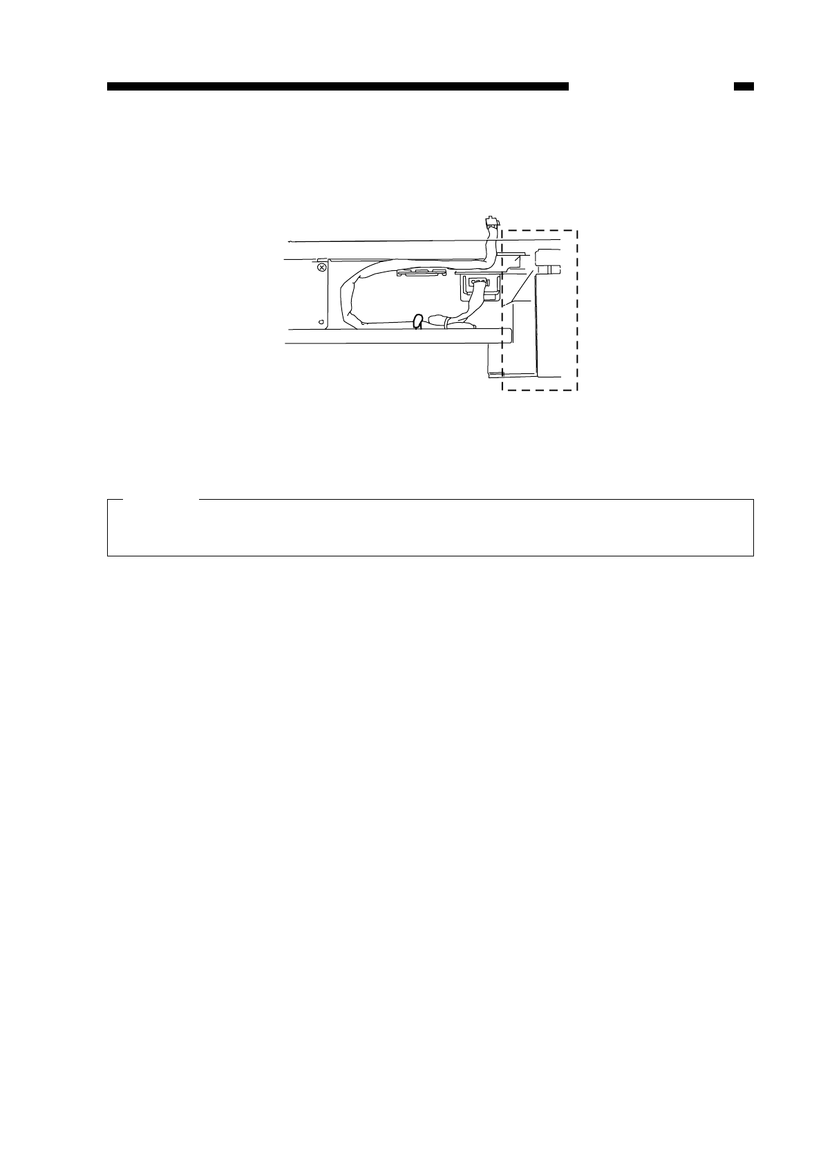
• Cassette Feeding Module-B2
Figure 8-611
Caution:
Make sure that the relay harness is outside the area indicated by dashed lines to
prevent it from interfering with the feet of the cassette.
12) Install the rear cover of the cassette pedestal and all covers.
13) Install the copier’s rear cover.
COPYRIGHT
©
1997 CANON INC. CANON NP6218 REV. 0 MAY 1997 PRINTED IN JAPAN (IMPRIME AU JAPON)
8-25
CHAPTER 8 INSTALLATION
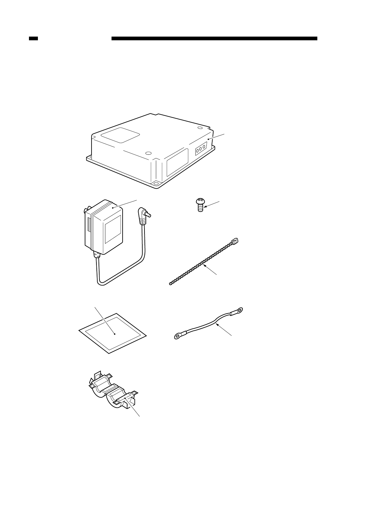
VII. INSTALLING THE REMOTE DIAGNOSTIC
DEVICE II
A. Unpacking
Figure 8-701
qRDD ..........................................1 unit tSwitch setting label..................1 pcs.
wPower Supply Unit.....................1 unit yGrounding wire*.........................1 pc.
eScrew (M4×6)...........................4 pcs. uFerrite core ...............................1 pc.
rHarness band...........................2 pcs. *Not used.
COPYRIGHT
©
1997 CANON INC. CANON NP6218 REV. 0 MAY 1997 PRINTED IN JAPAN (IMPRIME AU JAPON)
8-26
CHAPTER 8 INSTALLATION
u
q
t
we
r
y*Not used
*Not used
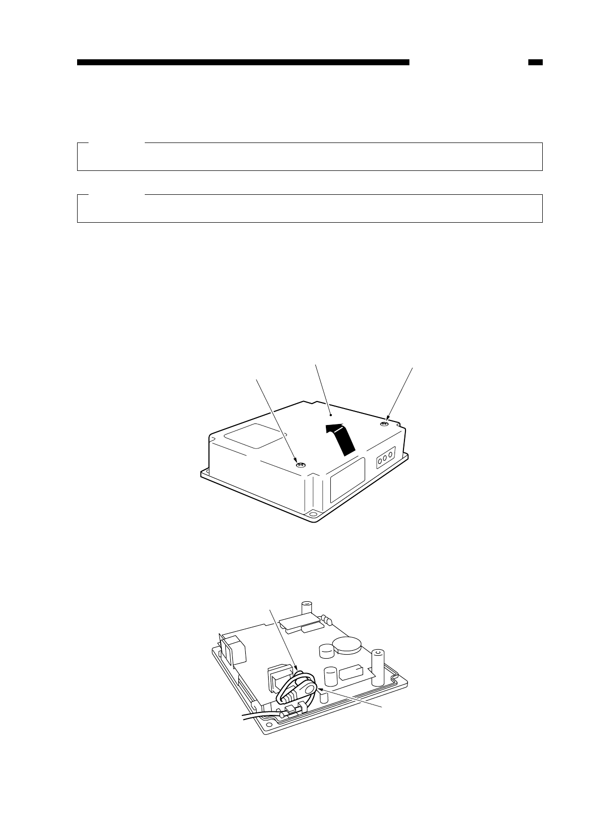
B. Installation to the Copier
Caution:
This model may not be available for sale in some areas.
Caution:
Keep the following in mind when installing the RDD to the copier:
1. This Accessory is to be installed by a qualified personal.
2. Make sure the copier has been properly installed before starting the work.
3. Keep the copier’s power cord disconnected during the work.
4. Be sure to use the appropriate screws (length, diameter).
5. Make sure the computer in the service station has been properly loaded with the
RDD’s settings data.
1) Remove the two screws wto detach the RDD’s top cover q.
Figure 8-702
2) Connect the Power Supply Unit’s connector eto the RDD’s connector ras shown.
Figure 8-703
COPYRIGHT
©
1997 CANON INC. CANON NP6218 REV. 0 MAY 1997 PRINTED IN JAPAN (IMPRIME AU JAPON)
8-27
CHAPTER 8 INSTALLATION
w
qw
r
e
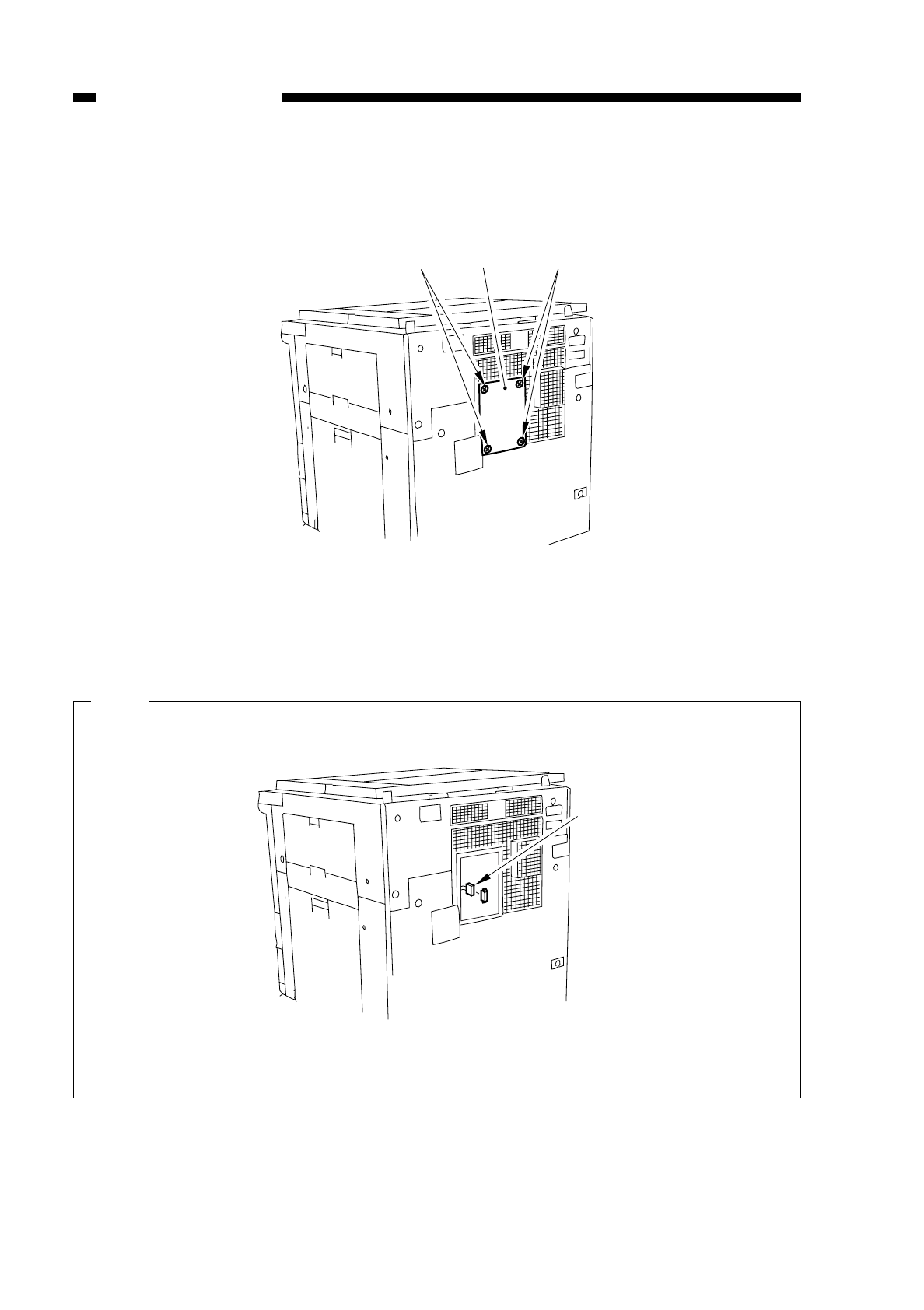
3) Remove the two screws y, and detach the face cover tfrom the copier’s rear cover.
Fig. 8-704
4) Connect the cable oon the copier side and the RDD’s cable i.
Note:
If a conversion connector is found on the cable !1 from the copier, remove it.
Fig. 8-705
COPYRIGHT
©
1997 CANON INC. CANON NP6218 REV. 0 MAY 1997 PRINTED IN JAPAN (IMPRIME AU JAPON)
8-28
CHAPTER 8 INSTALLATION
y y
t
o
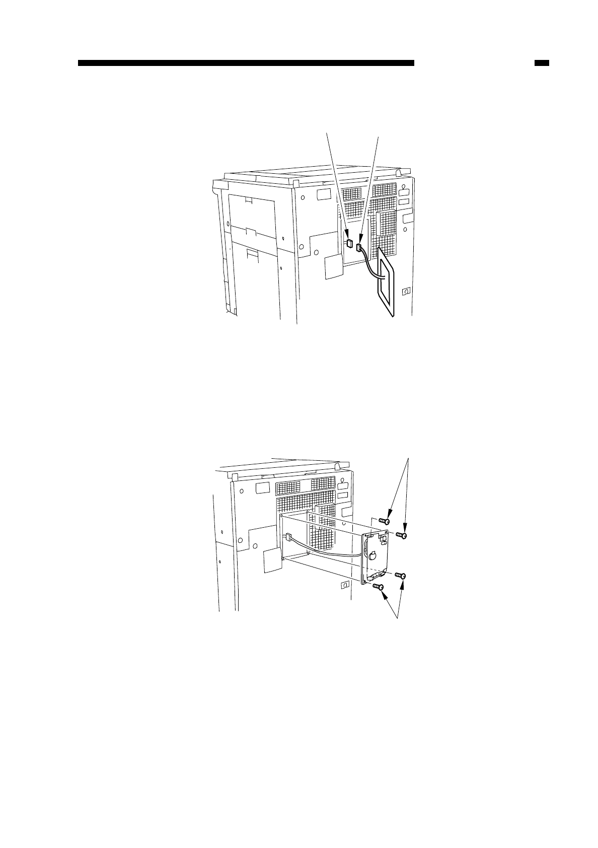
Fig. 8-706
5) Fix the RDD in place on the copier’s rear cover with four screws y; use the screws
removed from the copier.
Modular Jack on the Right
Fig. 8-707
COPYRIGHT
©
1997 CANON INC. CANON NP6218 REV. 0 MAY 1997 PRINTED IN JAPAN (IMPRIME AU JAPON)
8-29
CHAPTER 8 INSTALLATION
i
o
y
y
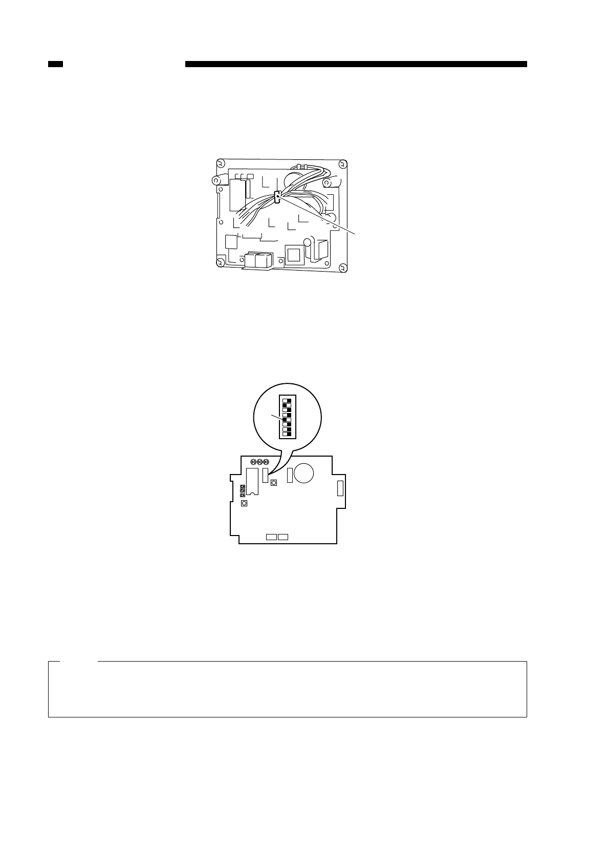
6) Remove the slack from the cable between the copier and the RDD; keep the excess
cable to the RDD using the harness band !0.
Fig. 8-708
7) Shift bit 4 of the DIP switch 2 !1 to ON so that the communication mode between the
RDD and the copier is IPC mode.
Fig. 8-709
8) If the ROM IC6 !2 is mounted on the RDD’s PCB, shift bit 7 of the DIP switch 2 !3 to
ON; otherwise, shift bit 7 of the DIP switch 2 to OFF.
Note:
1. If the ROM (IC6; !2) is not mounted, you need not mount it.
2. If you are mounting or replacing the ROM (IC6; !2 for upgrading the RDD, be
sure to shift bit 7 of the DIP switch 2 !3 to ON.
COPYRIGHT
©
1997 CANON INC. CANON NP6218 REV. 0 MAY 1997 PRINTED IN JAPAN (IMPRIME AU JAPON)
8-30
CHAPTER 8 INSTALLATION
!0
LED1 LED2 LED3
2
1
LED5
LED6
LED4
IC6
SW1
SW4 SW3
6
1
BAT1
CN4
1
2
CN3 CN2
12345678
!1
SW2
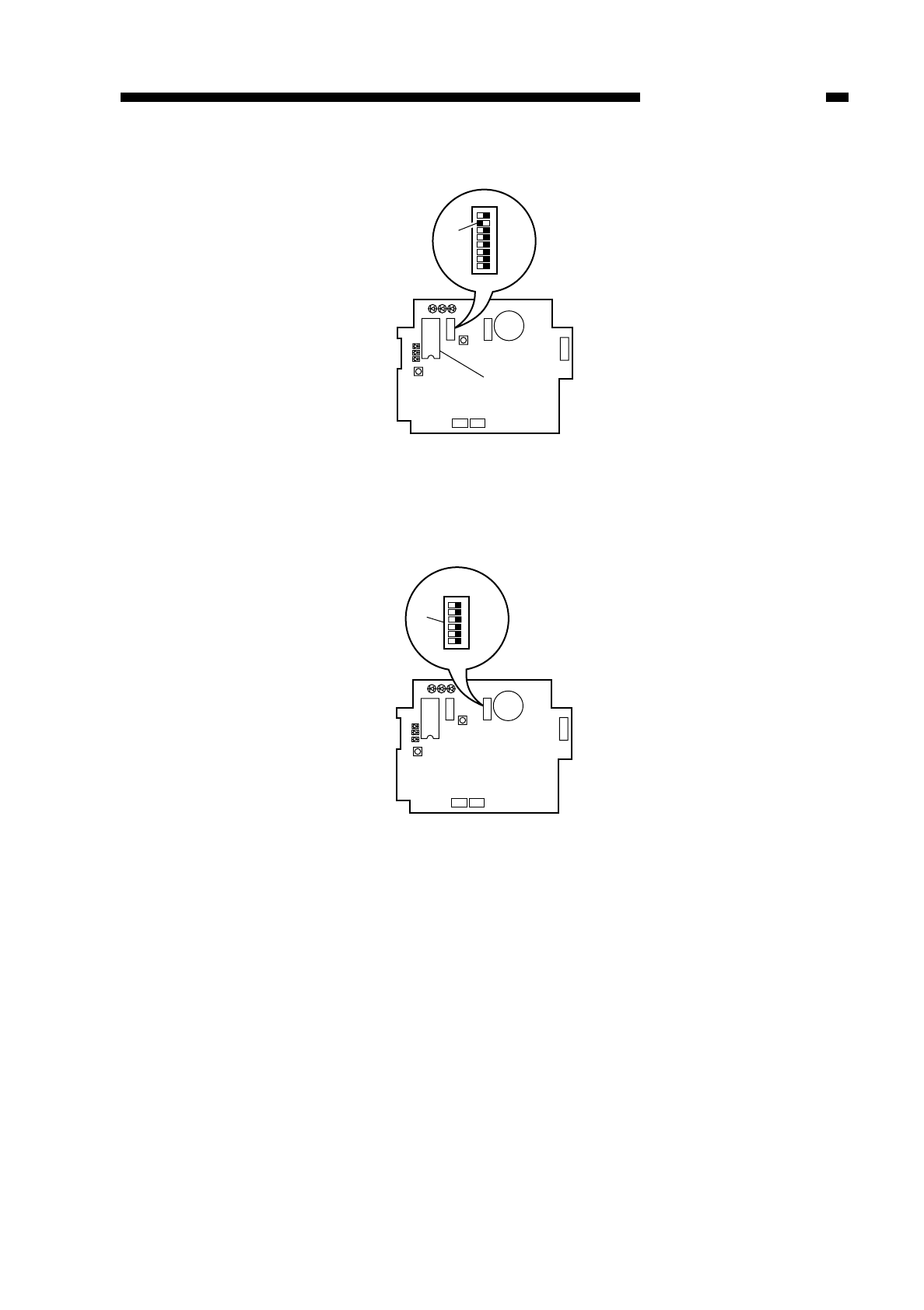
Fig. 8-710
9) Set the bits of the DIP switch 3 !4 on the RDD’s PCB as indicated in the table.
Fig. 8-711
COPYRIGHT
©
1997 CANON INC. CANON NP6218 REV. 0 MAY 1997 PRINTED IN JAPAN (IMPRIME AU JAPON)
8-31
CHAPTER 8 INSTALLATION
LED1 LED2 LED3
2
1
LED5
LED6
LED4
IC6
SW1
SW4 SW3
6
1
BAT1
CN4
1
2
CN3 CN2
12345678
SW2
!3
!2
LED1 LED2 LED3
2
1
LED5
LED6
LED4
IC6
SW1
SW4 SW3
6
1
BAT1
CN4
1
2
CN3 CN2
SW2
123456
!4
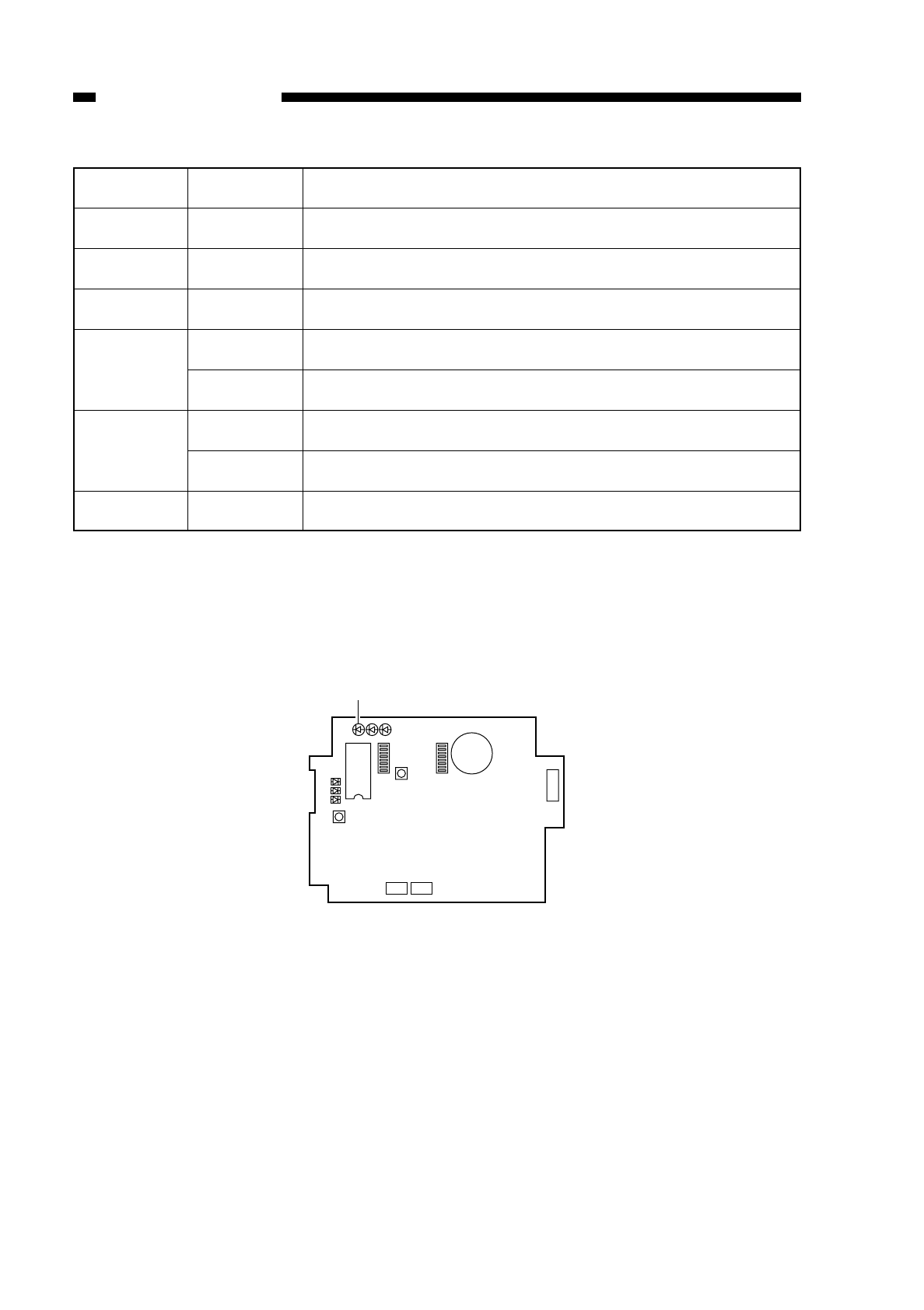
Table 8-701
10) Fit the Power Supply Unit into the power plug, and check that LED 1 !5 (green) on
the RDD’s PCB comes on.
Fig. 5-712
COPYRIGHT
©
1997 CANON INC. CANON NP6218 REV. 0 MAY 1997 PRINTED IN JAPAN (IMPRIME AU JAPON)
8-32
CHAPTER 8 INSTALLATION
Switch
SW3-1
SW3-2
SW3-3
SW3-4
SW3-5
SW3-6
Setting
AII
OFF
ON
ON
OFF
ON
OFF
–
Description
selects push pulse for RDD circuit confihuration
selscts dial pulse for RDD circuit confihuration
sets dial pulse speed to 20 PPS
sets dial pulse speed to 10 PPS
reserved
LED1 LED2 LED3
2
1
LED5
LED6
LED4
IC6
SW1
SW4 SW3
6
1
BAT1
CN4
1
2
CN3 CN2
!5
SW2
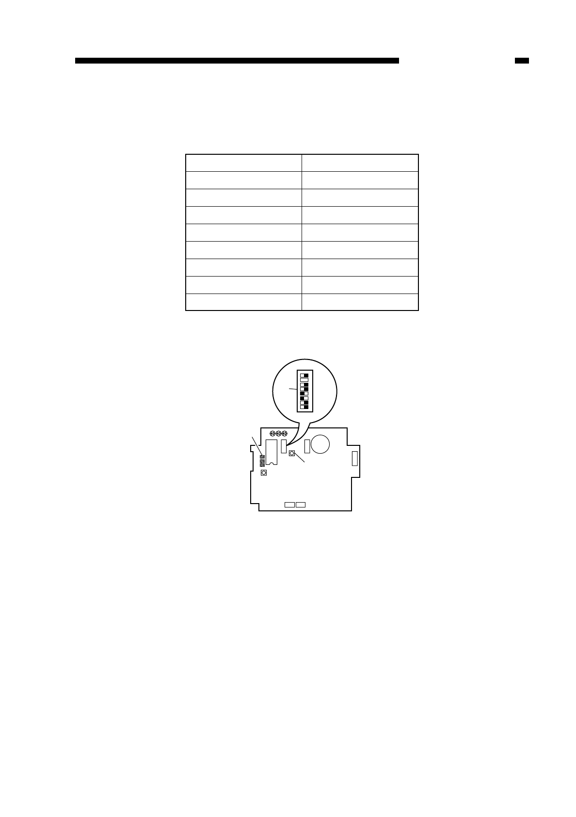
11) Reset the RDD’s RAM.
Set the bits on the DIP switch 2 !6 on the RDD’s PCB as indicated in the table, and
press the push switch 4 !7 to make sure that LED5 !8 (red) comes on.
Table 8-702
Fig. 8-713
COPYRIGHT
©
1997 CANON INC. CANON NP6218 REV. 0 MAY 1997 PRINTED IN JAPAN (IMPRIME AU JAPON)
8-33
CHAPTER 8 INSTALLATION
LED1 LED2 LED3
2
1
LED5
LED6
LED4
IC6
SW1
SW4 SW3
6
1
BAT1
CN4
1
2
CN3 CN2
12345678
!6
SW2
!7
!8
bits on SW2
SW2-1
SW2-2
SW2-3
SW2-4
SW2-5
SW2-6
SW2-7
SW2-8
Setting
OFF
OFF
ON
ON
OFF
OFF
See step 9).
OFF
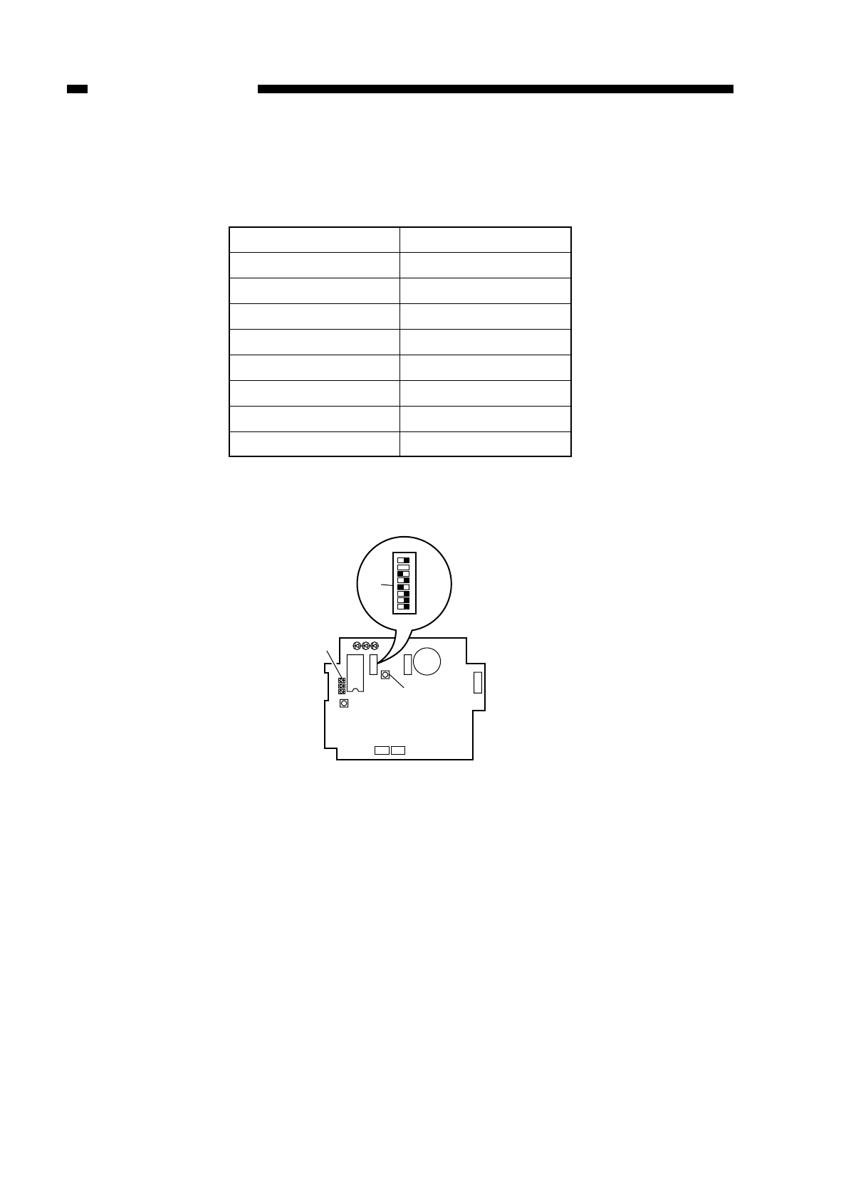
12) After making sure that LED5 !8 (red) has come on, set the bits on the DIP switch 2
!6 on the RDD’s PCB as indicated in the table, and press the push switch 4 !7 to
make sure that LED5 !8 (red) goes out, indicating that the RAM has been reset.
Table 8-703
Fig. 8-714
COPYRIGHT
©
1997 CANON INC. CANON NP6218 REV. 0 MAY 1997 PRINTED IN JAPAN (IMPRIME AU JAPON)
8-34
CHAPTER 8 INSTALLATION
bits on SW2
SW2-1
SW2-2
SW2-3
SW2-4
SW2-5
SW2-6
SW2-7
SW2-8
Setting
OFF
OFF
OFF
ON
OFF
ON
See step 9).
OFF
LED1 LED2 LED3
2
1
LED5
LED6
LED4
IC6
SW1
SW4 SW3
6
1
BAT1
CN4
1
2
CN3 CN2
12345678
!6
SW2
!8
!7
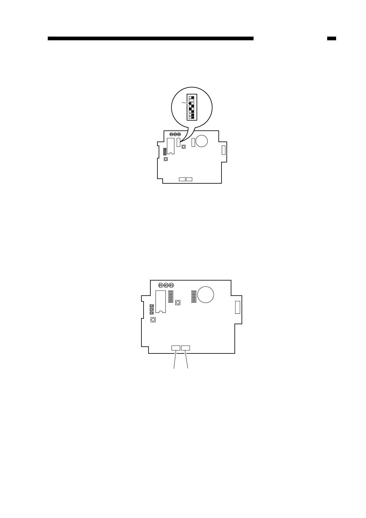
13) Shift bit 6 of the DIP switch 2 !9 on the RDD’s PCB to OFF.
Fig. 8-715
14) Connect the RDD to the telephone line.
If you are connecting the RDD on its own, connect the modular jack cable to the
RDD’s connector @0 (LINE).
If you will be using the RDD’s extra circuit, connect the existing telephone or fax
machine to the RDD’s connector @1 (TEL), and connect the telephone circuit to the
RDD’s connector @0 (LINE).
Fig. 8-716
COPYRIGHT
©
1997 CANON INC. CANON NP6218 REV. 0 MAY 1997 PRINTED IN JAPAN (IMPRIME AU JAPON)
8-35
CHAPTER 8 INSTALLATION
LED1 LED2 LED3
2
1
LED5
LED6
LED4
IC6
SW1
SW4 SW3
6
1
BAT1
CN4
1
2
CN3 CN2
12345678
!9
SW2
LED1 LED2 LED3
2
1
LED5
LED6
LED4
IC6
SW1
SW4 SW3
6
1
BAT1
CN4
1
2
CN3 CN2
@1 @0
SW2
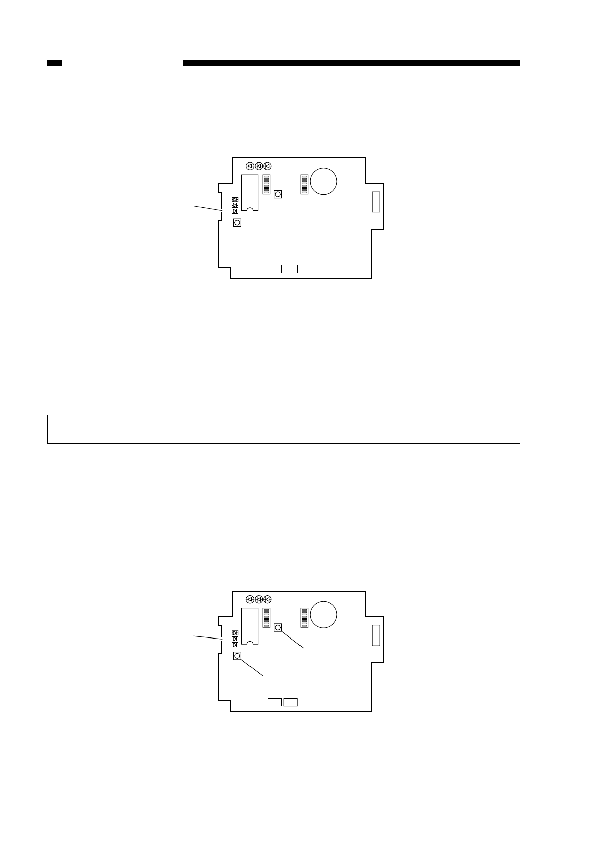
15) Call up the service station, and request the RDD’s initial settings. (LED 4 @2 (red)
starts to flash upon receipt.)
Fig. 8-717
16) Call up the service station to check if the initial settings have been successfully
made; if the attempt has failed, reset the RAM once again starting with step 11)
through 13).
Important:
You must confirm that the RDD’s settings are correct by calling the service station.
17) Check that you can place a telephone call from the RDD to the computer in the
service station.
Press the push switch 4 !7. LED6 @3 (red) should come on; it will go out when
transmission ends successfully, or will start to flash if transmission fails.
Retransmission is executed in response to a press on the push switch 4 !7 while
LED6 @3 is flashing.
Transmission is canceled in response to a press on the push switch 1 @4 while LED6
@3 is flashing.
Fig. 8-718
COPYRIGHT
©
1997 CANON INC. CANON NP6218 REV. 0 MAY 1997 PRINTED IN JAPAN (IMPRIME AU JAPON)
8-36
CHAPTER 8 INSTALLATION
LED1 LED2 LED3
2
1
LED5
LED6
LED4
IC6
SW1
SW4 SW3
6
1
BAT1
CN4
1
2
CN3 CN2
@2
SW2
LED1 LED2 LED3
2
1
LED5
LED6
LED4
IC6
SW1
SW4 SW3
6
1
BAT1
CN4
1
2
CN3 CN2
SW2
@4
!7
@3
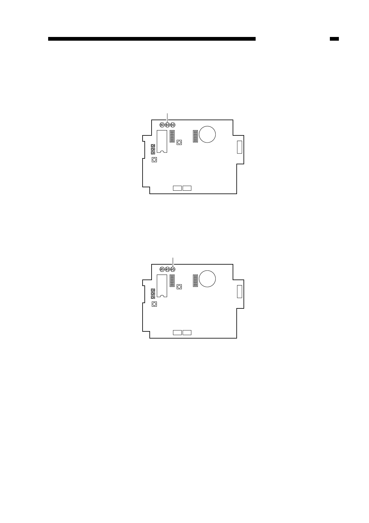
18) Check that the communications between the RDD and the copier are executed
normally.
Connect the copier’s power plug, and switch it on to make sure that LED 2 @5
(orange) flashes.
Fig. 8-719
19) Press the copier’ COPY START key to make sure that LED3 @6 (pink) flashes each
time a copy is delivered.
Fig. 8-720
COPYRIGHT
©
1997 CANON INC. CANON NP6218 REV. 0 MAY 1997 PRINTED IN JAPAN (IMPRIME AU JAPON)
8-37
CHAPTER 8 INSTALLATION
@5
LED1 LED2 LED3
2
1
LED5
LED6
LED4
IC6
SW1
SW4 SW3
6
1
BAT1
CN4
1
2
CN3 CN2
SW2
LED1 LED2 LED3
2
1
LED5
LED6
LED4
IC6
SW1
SW4 SW3
6
1
BAT1
CN4
1
2
CN3 CN2
SW2
@6
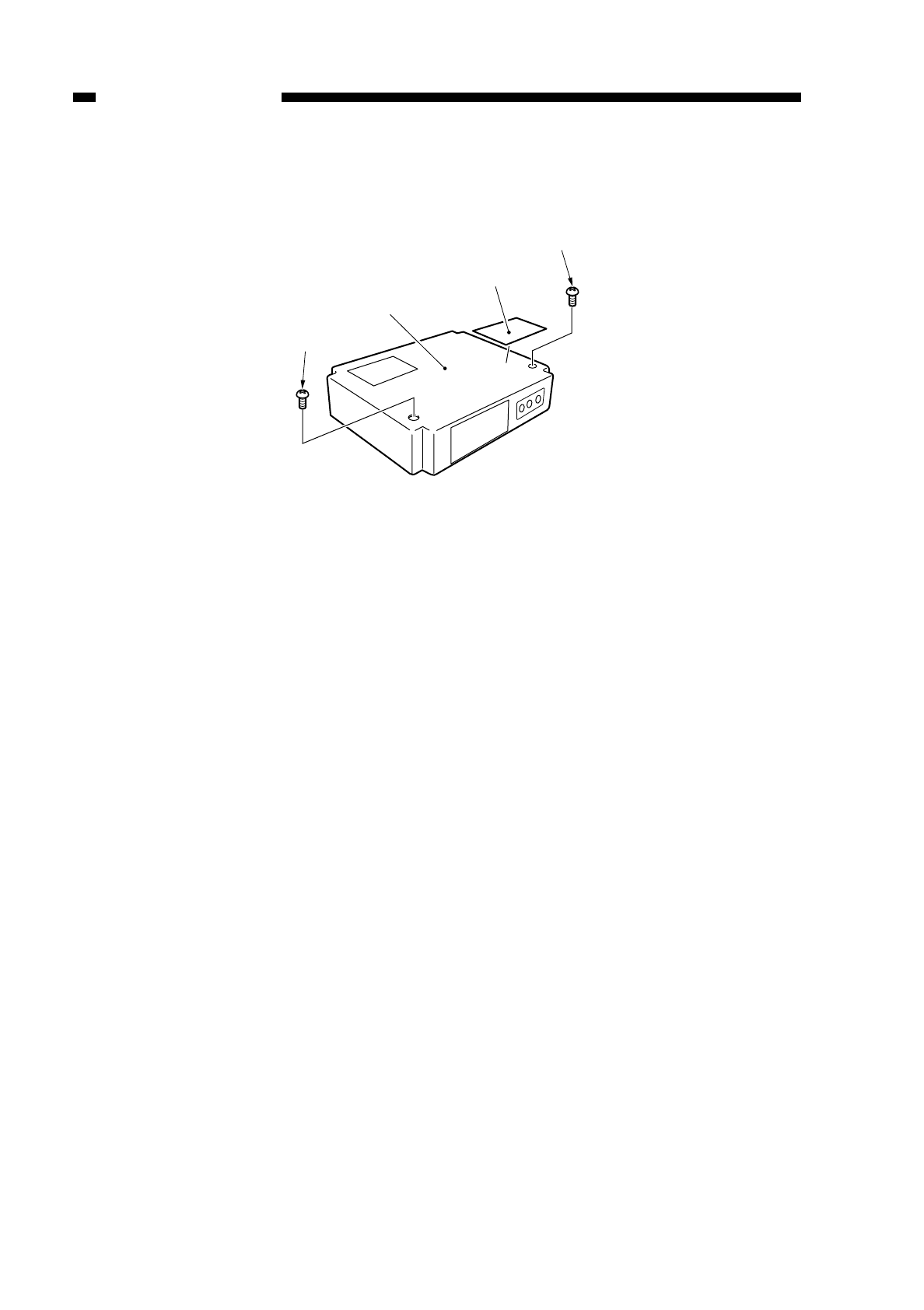
20) Attach the Switch setting label @7, to the RDD’s top cover q; then, record the setting
of each switch on the label.
Fig. 8-721
21) Fix the RDD’s top cover qin place using two screws w. (Make sure that the Power
Unit’s cable is fixed in place on the cable guide inside the RDD and is not trapped by
the top cover q.
COPYRIGHT
©
1997 CANON INC. CANON NP6218 REV. 0 MAY 1997 PRINTED IN JAPAN (IMPRIME AU JAPON)
8-38
CHAPTER 8 INSTALLATION
q
w
w
@7

CHAPTER 9
MAINTENANCE AND SERVICING
I. PERIODICALLY REPLACED
PARTS ................................................9-1
A. Periodically Replaced Parts...........9-1
II. DURABLES ........................................9-2
A. Copier............................................9-2
B. Cassette Feeding Module-B2/
Cassette Feeding Module-A2........9-3
III. PERIODICAL SERVICING .................9-4
IV. SERVICING CHART...........................9-5
V. NOTES ON DRUM KIT ......................9-6
This chapter provides tables of periodically replaced parts and consumables/durables and
scheduled servicing charts.
COPYRIGHT
©
1997 CANON INC. CANON NP6218 REV. 0 MAY 1997 PRINTED IN JAPAN (IMPRIME AU JAPON)

I. PERIODICALLY REPLACED PARTS
Some parts of the copier must be replaced on a periodical basis to ensure a specific
level of performance; replace them as indicated regardless of the presence of visible
damage.
Plan the replacement to coincide with a scheduled visit.
A. Periodically Replaced Parts
Note:
The above values are estimates only and subject to change based on the future
data.
CHAPTER 9 MAINTENANCE AND SERVICING
COPYRIGHT
©
1997 CANON INC. CANON NP6218 REV. 0 MAY 1997 PRINTED IN JAPAN (IMPRIME AU JAPON)
9-1
No.
1
Parts name
Static eliminator
as of JAN. 1997
Parts No.
FG5-2912
Q’ty
1
Life (copies)
60,000
Remarks

II. DURABLES
The parts shown in the table may require replacement because of deterioration or
damage over the period of warranty; replace them when they fail using the table as a
guide.
A. Copier
Note:
1.The life represents the number of copies actually made using the part.
2.The above values are estimates only and subject to change based on future data.
Remarks
See Note 1.
See Note 1.
See Note 1.
See Note 1.
Replace
with item 12
or 12-1
through 12-4
Parts name
Pick-up roller
Pick-up separation pad
Multifeeder pick-up roller
Multifeeder separation pad
Fluorescent lamp
Fixing cleaning roller
Transfer roller
Upper fixing unit 220/240V
Lower fixing roller
Lower fixing separation claw
Pre-exposure lamp
Developing assembly
Developing cylinder
Side seal
Developing blade unit
No.
1
2
3
4
5
6
7
8
9
10
11
12
12-1
12-2
12-4
Parts No.
FB3-5153-00P
FG5-2922-020
FB1-8581-000
FB2-2167-000
FH7-3271-000
FB3-4494-00P
FB2-2223-000
FG5-2928-140
FB2-2316-000
FB1-7275-000
FG5-2891-000
FG5-3275-04P
FB2-3834-000
FB2-3825-00P
FG5-7012-00P
Q’ty
2
1
1
1
1
1
1
1
1
1
1
1
1
2
1
Life (copies)
100,000
100,000
100,000
100,000
100,000
100,000
100,000
200,000
200,000
200,000
200,000
100,000
100,000
100,000
100,000
COPYRIGHT
©
1997 CANON INC. CANON NP6218 REV. 0 MAY 1997 PRINTED IN JAPAN (IMPRIME AU JAPON)
9-2
CHAPTER 9 MAINTENANCE AND SERVICING
as of JAN 1997

B. Cassette Feeding Module-B2/Cassette Feeding Module-A2
Note:
The above values are estimates only and subject to change based on future data.
COPYRIGHT
©
1997 CANON INC. CANON NP6218 REV. 0 MAY 1997 PRINTED IN JAPAN (IMPRIME AU JAPON)
9-3
CHAPTER 9 MAINTENANCE AND SERVICING
No.
1
2
Parts name
Pick-up roller
Pick-up separation pad
as of JAN 1997
Parts No.
FB2-2251-000
FG5-3614-000
Q’ty
1
1
Life (copies)
100,000
100,000
Remarks
Actual usage
Actual usage

III. PERIODICAL SERVICING
The copier does not have items that require periodical servicing; however, it is
recommended that the following work items be performed during any visit to the user’s.
COPYRIGHT
©
1997 CANON INC. CANON NP6218 REV. 0 MAY 1997 PRINTED IN JAPAN (IMPRIME AU JAPON)
9-4
CHAPTER 9 MAINTENANCE AND SERVICING
Work
Meet the person in charge of the
copier.
Make test copies in Direct,
Reduce, Enlarge, and page
separation.
Clean the static eliminator and
feeding assembly.
Clean the fixing/delivery assembly.
• paper guide plate
• separation claw
Perform work according to the number
of copies made (See p. 9-2).
Clean the copyboard cover and
copyboard glass.
Make test copies.
Make sample copies.
Arrange the sample copies, and
clean the area around the copier.
Record the final counter reading.
Fill out the Servicing Sheet, and
report to the person in charge.
Checks
Check the general
conditions.
Check the following:
a. image density
b. white background
for soiling
c. characters (clarity)
d. leading edge
(non-image width)
e. left/right margin
f. fixing, registra-
tion,back (soiling)
g. abnormal noise
h. counter (operation)
Step
1
2
3
4
5
6
7
8
9
10
11
Remarks
standard:
2.5 ±1.5 mm
(Direct, one-sided)
standard:
2.5 ±1.5 mm
(Direct/one-sided)
Use the special brush
(accessory) to clean
the static eliminator.
Use solvent.
Use solvent.
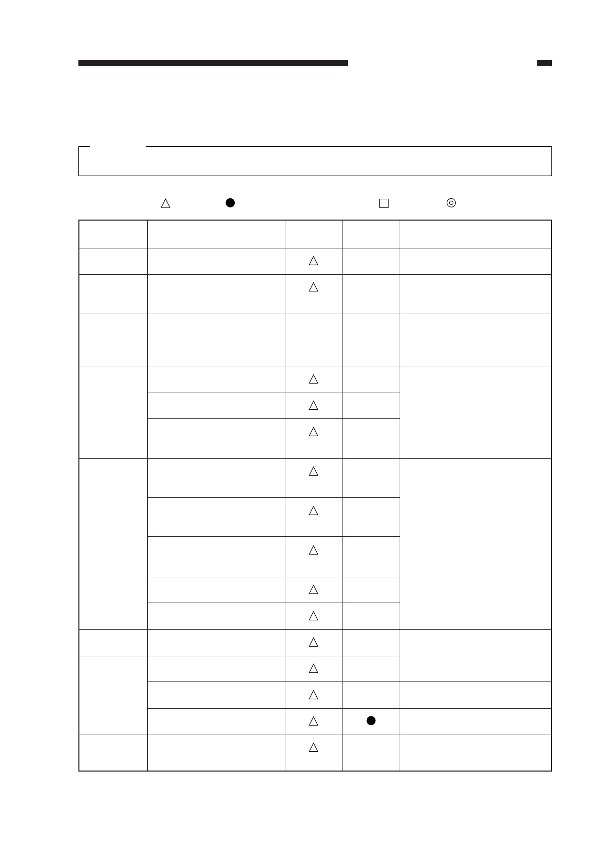
IV. SERVICING CHART
Caution:
Do not use solvents or oils other than those specified.
: clean : replace
✩: lubricate : adjust : inspector clean
COPYRIGHT
©
1997 CANON INC. CANON NP6218 REV. 0 MAY 1997 PRINTED IN JAPAN (IMPRIME AU JAPON)
9-5
CHAPTER 9 MAINTENANCE AND SERVICING
Parts
Copyboard glass
Pick-up roller
Scanner rail
Transfer guide assembly
Feeding belt
Feeding assembly
mount
Reflecting plate for
original exposure
Side reflecting plate for
original exposure
No. 1 through No. 6
mirrors
Lens
Dust-proofing glass
Clearner base
Charging roller
Charging roller cleaner
Static eliminator
Developing spacer
every
20,000
Unit
External
Pick-up
assembly
Scanner
drive
assembly
Feeding
assembly
Optical
assembly
Drum kit
Charging
assembly
Developing
assembly
Remarks
Use alcohol.
Use alcohol solution; then,
apply lubricant.
Use a moist cloth.
Use a blower brush; if the
soiling is excessive, use
alcohol.
Actual use of the drum kit.
every
60,000
✩
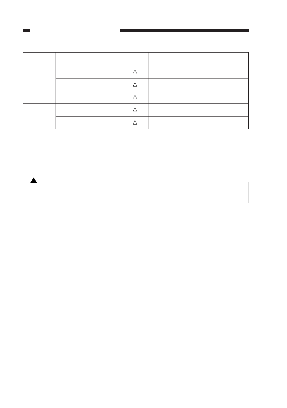
V. NOTES ON DRUM KIT
Caution:
Do NOT throw the drum kits into fire; it can burst or explode.
Otherwise, dispose of it as nonflammable material.
!
COPYRIGHT
©
1997 CANON INC. CANON NP6218 REV. 0 MAY 1997 PRINTED IN JAPAN (IMPRIME AU JAPON)
9-6
CHAPTER 9 MAINTENANCE AND SERVICING
Parts
Lower fixing roller
Separation claw (lower)
Fixing inlet guide
Delivery guide/ tray
Delivery spacer
every
20,000
Unit
Fixing
assembly
Delivery
assembly
every
60,000 Remarks
Use cleaning oil.
Use solvent.

COPYRIGHT
©
1997 CANON INC. CANON NP6218 REV. 0 MAY 1997 PRINTED IN JAPAN (IMPRIME AU JAPON)
CHAPTER 10
TROUBLESHOOTING
I. MAINTENANCE AND INSPECTION..10-3
A. Image Adjustment Basic
Procedure....................................10-3
B. Periodical Servicing.....................10-4
II. STANDARDS AND
ADJUSTMENTS...............................10-5
A. Image Adjustment .......................10-5
B. Exposure System ........................10-15
C. Image Formation System ............10-21
D. Pick-Up/Feeding System.............10-25
E. Fixing System..............................10-27
F. Electrical......................................10-35
III. TROUBLESHOOTING IMAGE
FAULTS.............................................10-45
A. Initial Checks...............................10-45
B. Samples of Image Faults ...........10-48
C. Troubleshooting Image Faults .....10-49
IV. TROUBLESHOOTING
MALFUNCTIONS .............................10-63
A. Troubleshooting Malfunctions......10-63
V. TROUBLESHOOTING FEEDING
PROBLEMS......................................10-78
A. Jams (copy paper).......................10-78
B. Feeding Faults.............................10-81
VI. ARRANGEMENT/FUNCTIONS OF
THE ELECTRICAL PARTS...............10-82
A. Sensors .......................................10-82
B. Clutches, Solenoids, and
Switches ......................................10-84
C. Motors, Heaters, and Lamps.......10-86
D. PCBs ...........................................10-88
E. Cassette Feeding Module-A2......10-90
F. Variable Resistors (VR) and check
Pins by PCB ................................10-92
VII. SERVICE MODE ..............................10-94
A. Outline .........................................10-94
B. Using Service Mode....................10-94
C. Control Display Mode [1].............10-97
D. I/O Mode [2] ................................10-99
E. Adjustment Mode [3] ...................10-102
F. Operation/Inspection Mode [4] ....10-105
G. Specification Settings Mode [5]...10-107
H. Counter Mode [6] ........................10-108
VIII. SELF DIAGNOSIS............................10-109
A. Copier..........................................10-109
B. Self Diagnosis (ADF)...................10-113
C. Self Diagnosis (Sorter)................10-114
This chapter provides tables of maintenance/inspection, standards/adjustments, and identification
(image fault/malfunction).
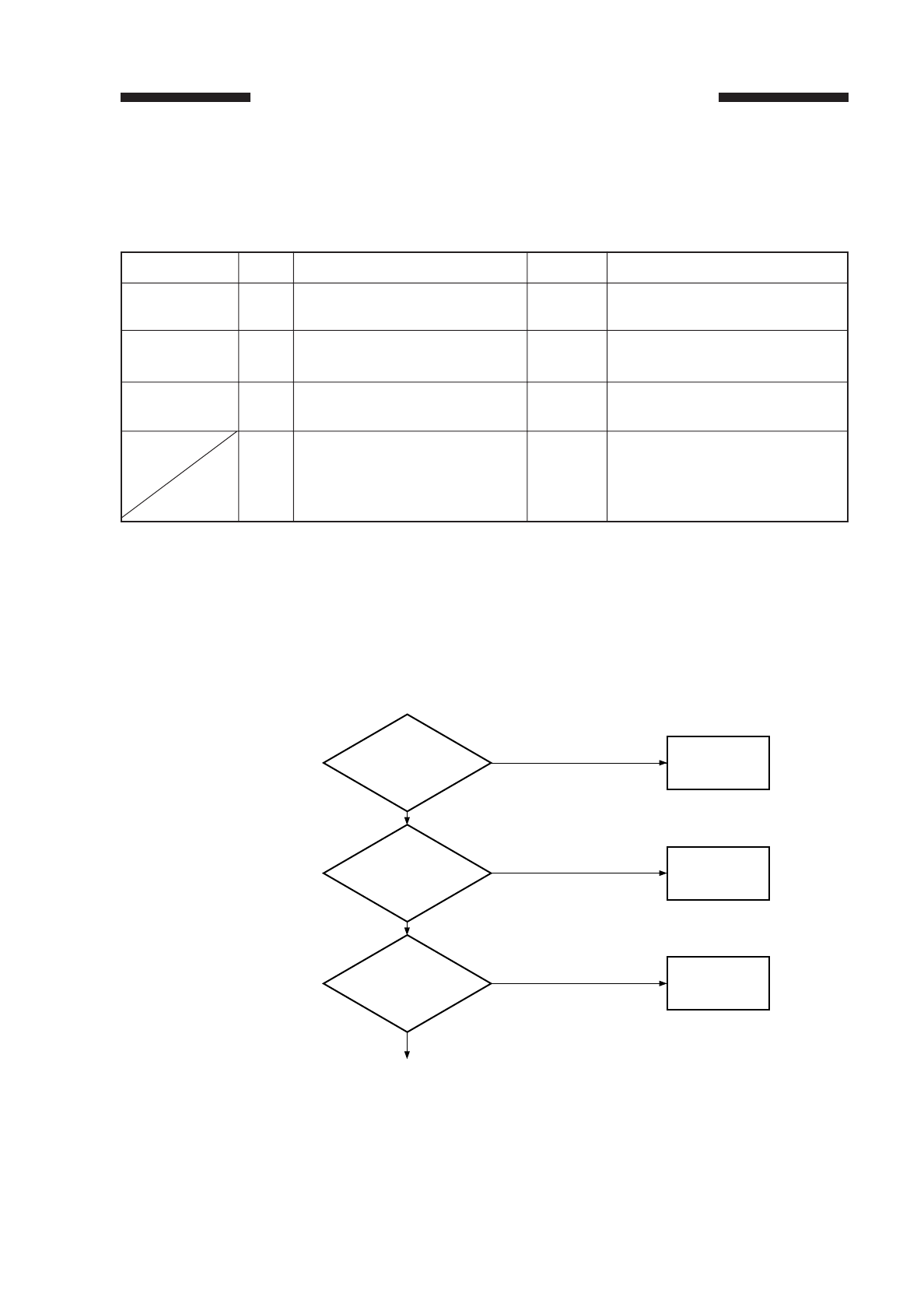
COPYRIGHT
©
1997 CANON INC. CANON NP6218 REV. 0 MAY 1997 PRINTED IN JAPAN (IMPRIME AU JAPON)
10-1
The troubleshooting procedures in this manual are prepared in the form of tables,
rather than flow charts. Study the following for an idea of how to consult the tables.
EX. AC power is absent.
■To find out the cause (faulty part) of a single problem, see the Cause/Fault column.
In the case of “AC power is absent,” you will learn that the power plug may not be
connected, the covers may not be closed properly, or the main power may be absent.
■To find out checks to make or remedies to provide for a single problem, see the
Remedy column as guided by YES/NO to the checks; or, move to the next step as
necessary.
■The instruction “Measure the voltage between J109-1 (+) and J109-2 (–) on the DC
controller PCB” asks you to connect the meter’s positive probe (+) to J109-1 and
negative probe to J109-2 (–).
Is the power
plug connected to
the outlet?
Connect the
plug
Checks YES/NO Remedies
NO
1
Step
Are the front door
and delivery cover
closed properly?
Close the door
and cover.
NO
2
Is the specified
voltage present at the
power outlet?
The problem is not
the copier’s: advise
the user.
NO
3
YES
YES
YES
Guide to Troubleshooting Tables
Cause/Fault
Power plug
Covers
Main power
Step
1
2
3
4
YES/NO
NO
NO
NO
YES
Checks
Is the power plug
connected to the outlet?
Are the front door and deliv-
ery cover closed properly?
Is the specified voltage
present at the power outlet?
Is the specified voltage pre-
sent between J1-1 and J1-
2? (J1 is located near the
power supply cord mount.)
Remedies
Connect the plug.
Close the door and cover.
The problem is not the
copier’s; advise the user.
Go to step 6.

COPYRIGHT
©
1997 CANON INC. CANON NP6218 REV. 0 MAR. 1997 PRINTED IN JAPAN (IMPRIME AU JAPON)
CHAPTER 10 TROUBLESHOOTING
10-2
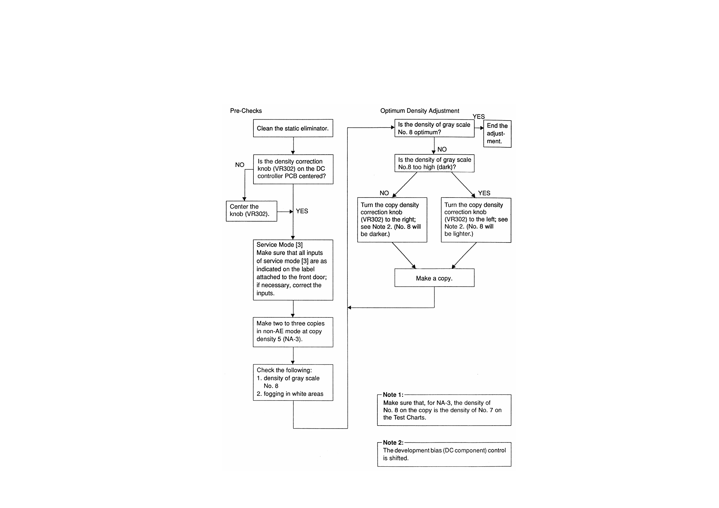
COPYRIGHT
©
1997 CANON INC. CANON NP6218 REV. 0 MAY 1997 PRINTED IN JAPAN (IMPRIME AU JAPON)
10-3
I MAINTENANCE AND INSPECTION
A. Image Adjustment Basic Procedure
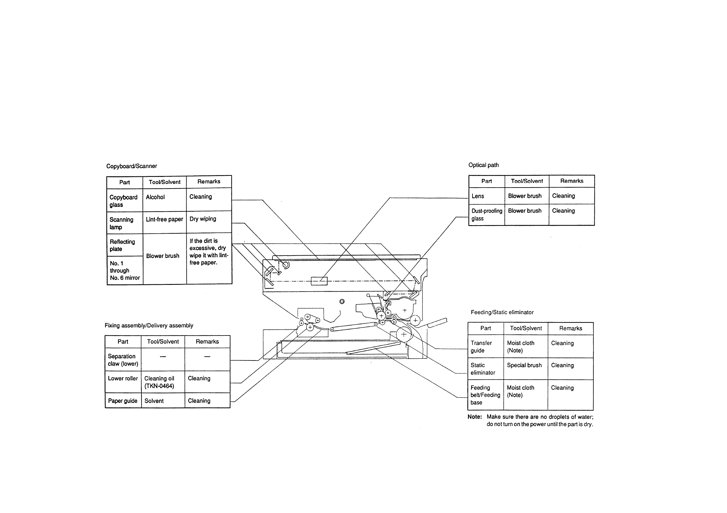
B. Periodical Servicing
10-4
COPYRIGHT
©
1997 CANON INC. CANON NP6218 REV. 0 MAY 1997 PRINTED IN JAPAN (IMPRIME AU JAPON)
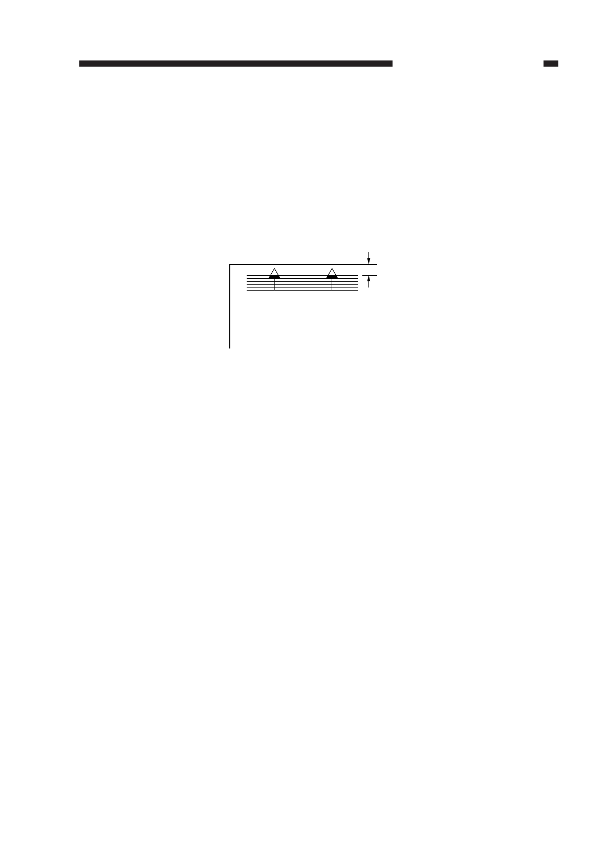
II. STANDARDS AND ADJUSTMENTS
A. Image Adjustment
1. Adjusting the Image Leading Edge Margin ([3], No. 305; registration ON timing)
Activate [3] in service mode, and select ‘No. 305’ (leading edge margin adjustment),
and make adjustments so that the image position is as indicated in Figure 10-201 when
the Test Sheet is copied in Direct.
Figure 10-201
Making Adjustments
1) Activate [3] in service mode, and select ‘No. 305’ using the keypad.
• The copy count indicator flashes ‘No. 305’.
2) Press the Start key.
3) Change the value using the keypad.
• The value flashes.
• If the value is negative, ‘%’ turns on. To enter a negative value, press the % key,
then enter the value using the keypad.
4) Press the AE key.
• The value flashes as soon as it is entered.
• Press the Start key to start copying operation.
5) To change a value continuously, repeat steps 1) through 4).
6) Press the Clear key to return to selecting items.
The relationship between the setting and the image position is as follows:
• For each ‘1’ in the setting, the position shifts about 0.27 mm.
• ‘+’ shifts the image forward.
10-5
CHAPTER 10 TROUBLESHOOTING
COPYRIGHT
©
1997 CANON INC. CANON NP6218 REV. 0 MAY 1997 PRINTED IN JAPAN (IMPRIME AU JAPON)
2.5±1.5mm
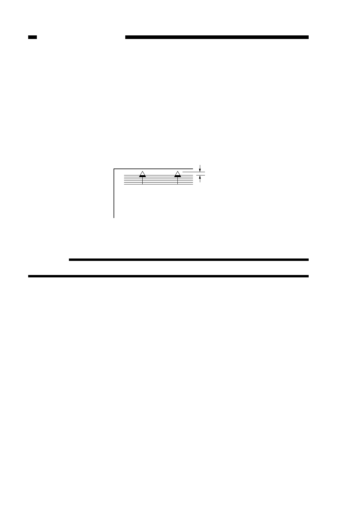
2. Adjusting the Leading Edge Non-Image Width ([3], No. 306; blank shutter ON
timing)
Activate [3] in service mode, select ‘No. 306’ (leading edge non-image width
adjustment), and make adjustments so that the image leading edge non-image width is
as indicated in Figure 10-202 when the Test Sheet is copied in Direct.
The copier varies the image leading edge non-image width by varying the timing at
which the blank shutter is closed.
You must make this adjustment whenever you have replaced the blank shutter
solenoid or the blank exposure assembly.
Leading Edge Non-Image Width
Figure 10-202
Reference:
6 mm or less in Reduce/Enlarge mode.
Making Adjustments
1) Activate [3] in service mode, and select ‘No. 306’ using the keypad.
• The copy count indicator flashes ‘No. 306’.
2) Press the Start key.
3) Change the value using the keypad.
• The value flashes.
• If the value is negative, ‘%’ turns on. To enter a negative value, press the % key,
then enter the value using the keypad.
4) Press the AE key.
• The value flashes as soon as it is entered.
• Press the Start key to start copying operation.
5) To change a value continuously, repeat steps 1) through 4).
6) Press the Clear key to return to selecting items.
The relationship between the setting and the image position is as follows:
• For each ‘1’ in the setting, the position shifts about 0.27 mm.
• ‘+’ increases the non-image width.
10-6
CHAPTER 10 TROUBLESHOOTING
COPYRIGHT
©
1997 CANON INC. CANON NP6218 REV. 0 MAY 1997 PRINTED IN JAPAN (IMPRIME AU JAPON)
2.0±1.0mm

3. Adjusting the Image Trailing Edge Non-Image Width ([3], No. 309; blank shutter
timing)
Trailing Edge Non-Image Width
Figure 10-203
Activate [3] in service mode, and select ‘No. 309’ (leading edge non-image width
adjustment); make adjustments so that the image trailing edge non-image width is as
indicated in Figure 10-203 when the Test Sheet is copied in Direct.
The copier varies the image trailing edge non-image width by varying the timing at
which the blank shutter is opened.
Making Adjustments
1) Activate [3] in service mode, and select ‘No. 309’ using the keypad.
• The copy count indicator flashes ‘No. 309’.
2) Press the Start key.
3) Change the value using the keypad.
• The value flashes.
• If the value is negative, ‘%’ turns on. To enter a negative value, press the % key,
then enter the value using the keypad.
4) Press the AE key.
• The value flashes as soon as it is entered.
• Press the Start key to start copying operation.
5) To change a value continuously, repeat steps 1) through 2).
6) Press the Clear key to return to selecting items.
The relationship between the setting and the image position is as follows:
• For each ‘1’ in the setting, the position shifts about 0.27 mm.
• ‘+’ decreases the trailing edge non-image width.
10-7
CHAPTER 10 TROUBLESHOOTING
COPYRIGHT
©
1997 CANON INC. CANON NP6218 REV. 0 MAY 1997 PRINTED IN JAPAN (IMPRIME AU JAPON)
2.5±
1.5mm
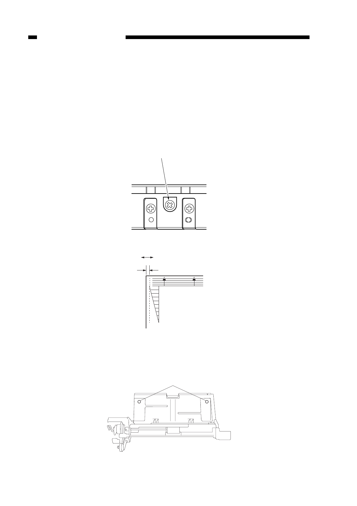
4. Adjusting the Left/Right Registration
Make adjustments so that the position of the image is as indicated in Figure 10-205
when the Test Sheet is copied in Direct.
a. Pick-Up from the Cassette
Turn the screw 1 shown in Figure 10-204 to adjust the position of the cassette hook
plate.
standard: 0.±1.5 mm
clockwise turn: paper moves in the direction of – shown in Figure 10-205.
counterclockwise turn: paper moves in the direction of + in Figure 10-205.
Figure 10-204
Figure 10-205
b. Pick-Up from the Multifeeder
Loosen the screw 1, and move the position of the tray so that it is 0 ±1.5 mm.
Figure 10-206
10-8
CHAPTER 10 TROUBLESHOOTING
COPYRIGHT
©
1997 CANON INC. CANON NP6218 REV. 0 MAY 1997 PRINTED IN JAPAN (IMPRIME AU JAPON)
q
(-) (+)
0±1.5mm
0
2
4
6
8
10
q
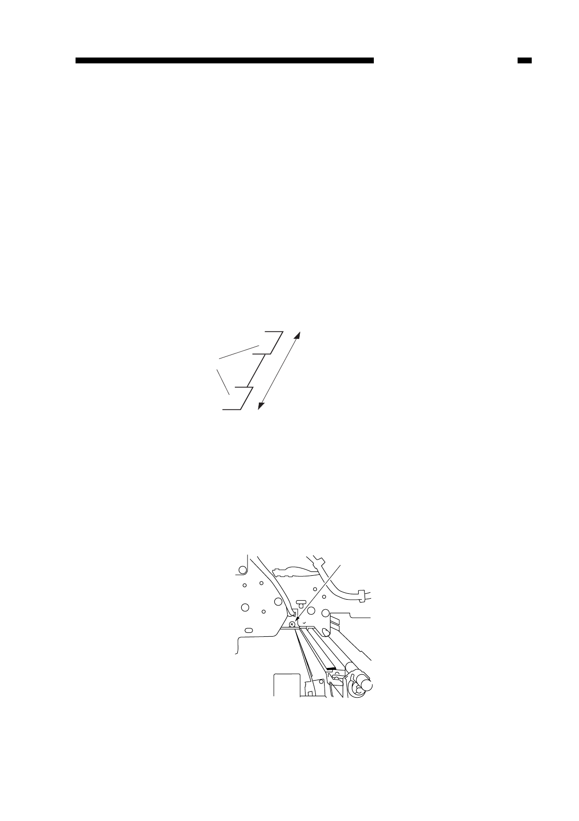
5. Adjusting the Left/Right Margin (No. 311; left/right margin)
Select ‘No. 311’ (left/right margin adjustment); make adjustments so that the left/right
margin is 2.5 ±1.5 mm when the Test Sheet is copied in Direct.
You must adjust the left/right registration before making this adjustment.
Making Adjustments
a. Margin (adjusting the width)
1) Activate [3] in service mode, and select ‘No. 311’ using the keypad.
2) Press the Start key.
3) Enter a value using the keypad.
• If the value is negative, ‘%’ turns on. To enter a negative value, press the % key,
then enter the value using the keypad.
The relationship between the setting and the image position is as follows:
• For each ‘1’ in the setting, the margin (one side) shifts about 0.37 mm.
• range: 0 to 15 mm
• ‘+’ increases the margin.
• ‘–’ decreases the margin.
Figure 10-207
b. Left/Right Margin
Turn the blank shutter adjustment screw located on the front side plate shown in
Figure 10-208 so that the value is as specified.
clockwise turn:moves the margin toward the front.
counterclockwise turn:moves the margin toward the rear.
a full turn: shifts the margin by about 1 mm.
Figure 10-208
10-9
CHAPTER 10 TROUBLESHOOTING
COPYRIGHT
©
1997 CANON INC. CANON NP6218 REV. 0 MAY 1997 PRINTED IN JAPAN (IMPRIME AU JAPON)
Shutter
Adjust the distance between the
two shutters in the blanking
assembly.
q

Figure 10-209
Caution:
After the adjustments (both a and b), turn on and off the power switch or change
the reproduction ratio so that the blank exposure assembly performs home
positioning.
6. Adjusting the Scanning Lamp Intensity
Turn VR301 on the DC controller as follows whenever you have replaced the
scanning lamp, intensity sensor, or DC controller.
1) Set Test Sheet NA3 on the copyboard, and close the copyboard cover.
2) Adjust the copy density (AE off) to electrical central position (service mode 1/0 mode
[2] No. 212 Value = 153~159).
❋ Without this adjustment, exposure value becomes invalid.
3) Turn VR301 on the DC controller so that the image is optimum.
• If the image is too light, turn the VR slightly clockwise.
• If the image is too dark, turn the VR slightly counterclockwise.
Reference:
1. The term optimum image refers to a copy whose gray scale No. 8 corresponds to
gray scale No. 4 through 7 of the Test Sheet without fogging.
2. An excessive turn on the VR could put out the lamp. If that is the case, turn it
clockwise until it stops, and turn off and then on the power for re-adjustment.
Caution:
Be sure to execute AE adjustment after these adjustments.
10-10
CHAPTER 10 TROUBLESHOOTING
COPYRIGHT
©
1997 CANON INC. CANON NP6218 REV. 0 MAY 1997 PRINTED IN JAPAN (IMPRIME AU JAPON)
Shutter
The entire shutters are
shifted.

7. AE Adjustment
Adjust the AE mechanism using the following three service modes:
qAE Basic Adjustment
No. 410 .............scanner forward stop
No. 408 ........scanning lamp on check
No. 208 .....AE sensor voltage display
No. 301lamp intensity automatic adjustment at time of AE scan
wCopy Density in AE Mode (No. 302)
(developing bias) reference adjustment
eCopy Density in AE Mode
(developing bias) slope adjustment
If the copy density is not optimum after executing AE basic adjustment q(No. 410,
No. 408, No. 208, No. 301), execute wand then , if necessary, e, i.e., No. 302 and No.
303.
If you have replaced the AE sensor, scanning lamp, or DC controller, adjust the
scanning lamp intensity (VR 301); then, execute AE basic adjustment q, scanner
forward stop (No. 410), scanning lamp on check (No. 408), AE sensor voltage display
(No. 208), and lamp intensity automatic adjustment (No. 301).
Go through the following when making adjustments; Table 10-1 is a list of service
modes excluding scanner forward stop (No. 410), list of service modes excluding
scanner forward stop (No. 410), scanning lamp on check (No. 408), and AE sensor
voltage display (No. 208).
a. AE Basic Adjustment (No. 410, No. 408, No. 208, No. 301)
In this adjustment, the intensity of the scanning lamp is read by the lamp intensity
sensor and the voltage of the AE sensor unit is adjusted by VR 391 on the DC controller.
After the adjustment, execute the lamp intensity automatic adjustment for AE scans.
1) Place the Test Sheet NA-3 on the copyboard, and close the copyboard.
Adjust to the appropriate copy density in non-AE mode (settings) by suing bias
adjustment knob “VR302”. Then press the service mode switch (SW302) to activate
service mode.
2) Enter ‘4’ using the keypad, and press the AE key.
• The display indicates ‘401’.
3) Enter ‘410’ using the keypad.
• The display indicates ‘410’.
4) Press the Start key once.
• The scanner moves forward.
Caution:
Each press moves the scanner forward; do not press more than once.
5) Enter ‘408’ using the keypad, and press the Start key.
• The display indicates ‘ON’, and turns off after about 1.5 sec.
6) Press the Clear key twice.
• The display indicates ‘4’.
7) Press ‘2’ on the keypad, and press the AE key.
• The display indicates ‘201’.
10-11
CHAPTER 10 TROUBLESHOOTING
COPYRIGHT
©
1997 CANON INC. CANON NP6218 REV. 0 MAY 1997 PRINTED IN JAPAN (IMPRIME AU JAPON)
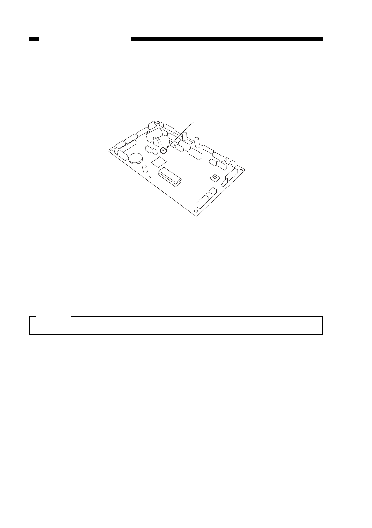
8) Enter ‘208’ using the keypad, and press the start button.
• The display indicates ‘208’.
9) Press the Start key.
• The display indicates ‘0–255’.
10) Turn VR391 on the DC controller so that the reading on the display is ‘100~105’.
Figure 10-210 DC Controller PCB
11) Turn off and on the power switch.
• This turns off and on the scanning lamp.
12) Press the service mode switch.
• The copier enters service mode, and the display indicates ‘1’.
13) Enter ‘3’ using the keypad, and press the AE key.
• The display indicates ‘301’.
14) Press the Start key.
Caution:
Wait until initial rotation is over.
• After initial rotation is over, the AE indicators starts to flash.
15) Press the AE key; the following take place to indicate that the optimum intensity is
adjusted automatically:
• The AE indicator stops flashing and remains on.
• The scanner moves to the AE measurement position.
• When the intensity has stabilized, the reading taken by the AE sensor is stored in
memory.
• The lamp is turned off, and the scanner is returned to its original position.
16) When the above has ended, press the clear key twice.
• The display indicated ‘3’.
17) Enter ‘1’ using the keypad, and press the AE key.
• The display indicates ‘101’.
18) Enter ‘116’ using the keypad, and press the Start key.
• Make sure that the display indicates ‘68–72’; otherwise, start with step 2) of
operation/inspection mode for re-adjustment.
10-12
CHAPTER 10 TROUBLESHOOTING
COPYRIGHT
©
1997 CANON INC. CANON NP6218 REV. 0 MAY 1997 PRINTED IN JAPAN (IMPRIME AU JAPON)
VR391

b. Copy Density (development bias) Reference Point Adjustment for AE Mode (No.
302)
1) If the indication is not in the 300’s, activate adjustment mode (service mode) as in the
case of ‘No. 301’.
2) Press [2] on the keypad.
• The copier indicates ‘302’.
3) Press the Start key.
• The copier indicates the current setting.
4) Change the setting using the keypad, and press the AE key.
• A higher setting causes the AE copies to be darker.
• default: 0
range: –26 to +26
• If the setting is negative, the ‘%’ is indicated. To enter a negative value, press the
‘%’ key, and enter a setting.
• When the copier has read the setting, the indication stops flashing and remains
on.
5) Record the new setting on the service mode label.
6) To end, press the Clear key.
• The copier returns to selection mode, and indicates ‘302’.
• As necessary, execute ‘No. 303’.
c. Copy Density (development bias) Slope Adjustment for AE Mode (No. 303)
1) If the indication is not in the 300’s, activate adjustment mode (service mode) as in the
case of No. 301.
2) Press [3] on the keypad.
• The copier indicates ‘303’.
3) Press the Start key.
• The copier indicates the current setting.
4) Change the setting with the keypad, and press the AE key.
• A larger setting causes the AE copies to be darker.
• default:.........................................0
range:...........................–26 to +26
• If the setting is negative, ‘%’ is indicated. To enter a negative value, press the ‘%’
key, and enter a setting.
• When the copier has read the setting, the indication stops flashing and remains
on.
5) Record the new settings on the service mode label.
6) Press the Reset key.
• The copier de-activates service mode.
10-13
CHAPTER 10 TROUBLESHOOTING
COPYRIGHT
©
1997 CANON INC. CANON NP6218 REV. 0 MAY 1997 PRINTED IN JAPAN (IMPRIME AU JAPON)
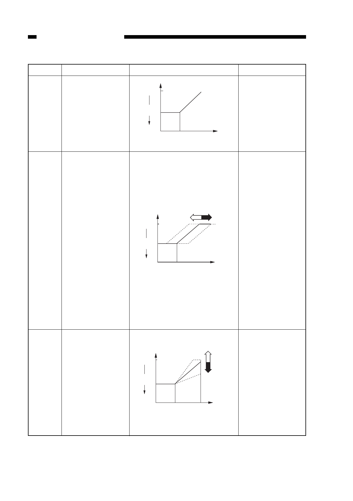
Table 10-201
10-14
CHAPTER 10 TROUBLESHOOTING
COPYRIGHT
©
1997 CANON INC. CANON NP6218 REV. 0 MAY 1997 PRINTED IN JAPAN (IMPRIME AU JAPON)
Function
Automatic lamp
intensity adjustment
for AE scans
Copy density
(development bias)
reference point
adjustment for AE
mode
Copy density
(development bias)
slope adjustment for
AE mode
Description
Lighter
Copy
density 5
Darker
Test Chart Density of
original
9
Remarks\
The lamp intensity
is automatically
adjusted so that the
copies of the Test
Chart will be made
at density 5.
qA lower setting in
service mode causes
the AE copies to be
darker.
wA higher settings
in service mode
causes the AE copies
to be lighter.
default: 0
range: –26 to +26
After adjustment with
the test sheet NA-3,
using AE mode,
density adjustment
should show ‘5
’.
In non-AE mode,
density ‘5’ must also
be apprppriate
(adjusted with knob
VR302).
qA higher setting
in service mode
causes copies of a
newspaper to be
lighter.
wA lower setting
in service mode
causes copies of a
newspaper to be
darker.
default: 0
range: –26 to +26
Item
No. 301
No. 302
No. 303
Test Chart Density of
original
Lighter
Copy
density 5
Darker
9
q
w
Test Chart Density of
original
Lighter
Copy
density 5
Darker
9
News-
paper
w
q
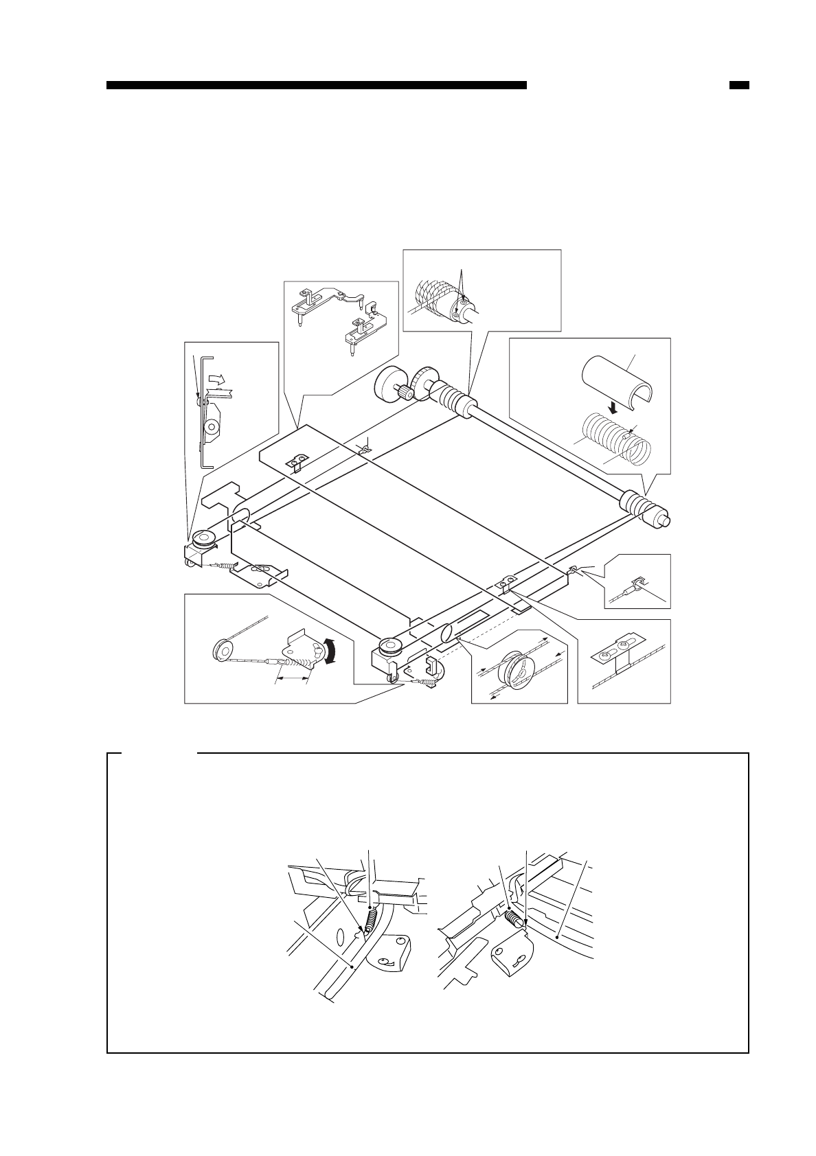
B. Exposure System
1. Routing the Scanner Drive Cable
Route the cable as shown by qthrough !0; then, adjust the cable tension and mirror
position as described.
Figure 10-211
Caution:
When attaching the wire spring, pay attention to the orientation of the spring; see
the diagrams below. If not attached correctly, its hook tip could interfere with the
cable.
Figure 10-212
10-15
CHAPTER 10 TROUBLESHOOTING
COPYRIGHT
©
1997 CANON INC. CANON NP6218 REV. 0 MAY 1997 PRINTED IN JAPAN (IMPRIME AU JAPON)
Screw
Loosen the
screw,and shift
it down.
Re-tighten
the screw.
Attach the mirror
positioning tool.
Set screws
Loosen the set
screws to enable
free rotation.
Put the steel ball
into the hole in
the pulley; wind
the cable nine
times toward the
inside, and four
times toward the
outside; then, snap
on the pulley clip.
Pulley clip
Steel ball
34±1mm
o
y
u
r
!1
t
q
!0
w
e
i
Wire spring
Wire spring
Hook Hook
Cable
Cable
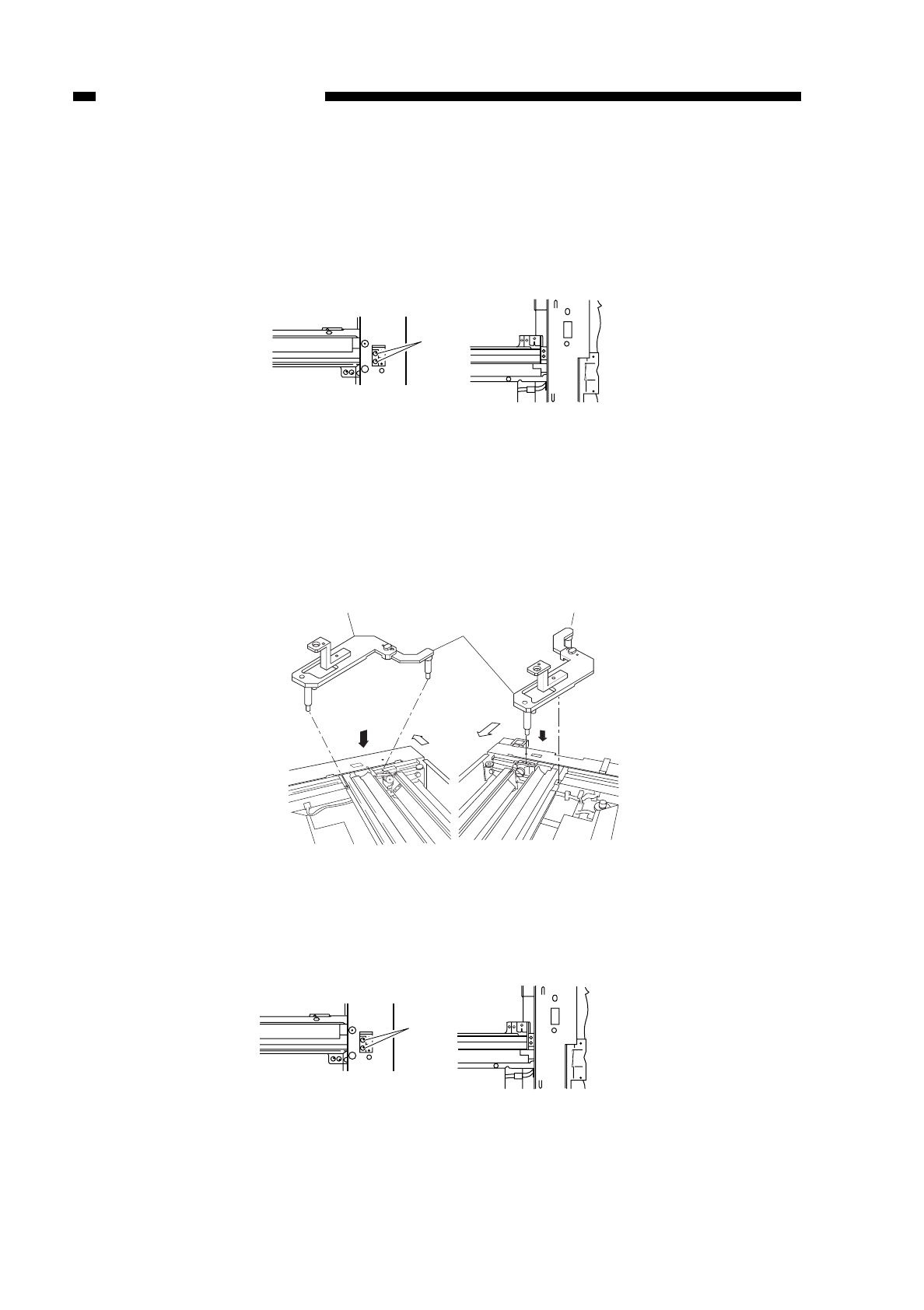
2. Adjusting the Mirror Position (optical distance between No. 1 mirror and No.
2/No. 3 mirror)
1) Keep the mirror positioning tool handy.
(See “4 Assembling the Mirror Positioning Tool on P. 10-17.”)
2) Move the No. 1 mirror mount forward, and match the long hole in the front side plate
and the cable fixing screw q.
Figure 10-213
3) Loosen the set screw on the pulley.
4) Set the mirror positioning tool wto the No. 1 mirror mount and the No. 2 mirror mount
(both front and rear).
Figure 10-214
5) Attach the scanner cable fixing to the No. 1 mirror mount using two screws e(both
front and rear).
Figure 10-215
10-16
CHAPTER 10 TROUBLESHOOTING
COPYRIGHT
©
1997 CANON INC. CANON NP6218 REV. 0 MAY 1997 PRINTED IN JAPAN (IMPRIME AU JAPON)
q
(front) (rear)
(front)
Mirror positioning tool (front) Mirror positioning tool (rear)
(front)
w
e
(front) (rear)
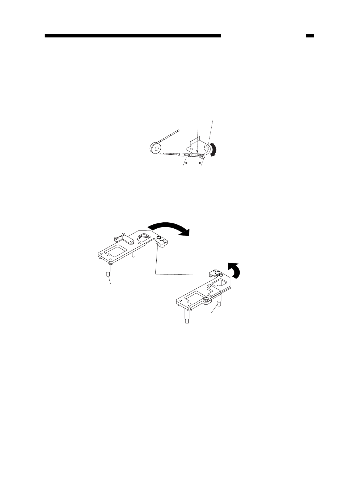
COPYRIGHT
©
1997 CANON INC. CANON NP6218 REV. 0 MAY 1997 PRINTED IN JAPAN (IMPRIME AU JAPON)
CHAPTER 10 TROUBLESHOOTING
10-17
6) Tighten the screw on the pulley.
7) Detach the positioning tool (FY9-3009).
3. Adjusting the Scanner Cable Tension
Move the tension plate and tighten the screw wso that the distance across the ends
of the cable spring qis 34 ±1 mm as indicated in Figure 10-216.
Figure 10-216
4. Assembling the Mirror Positioning Tool
1) Remove the screw found in position B.
Figure 10-217
2) Fit the screw removed in step 1) in position A, and tighten it slightly.
3) Extend the arm accommodated by the main frame unit it butts against the stopper as
in Figure 10-218.
qw
34±1mm
A
A
B
B
Position B
Longest pin
Medium-Length pin
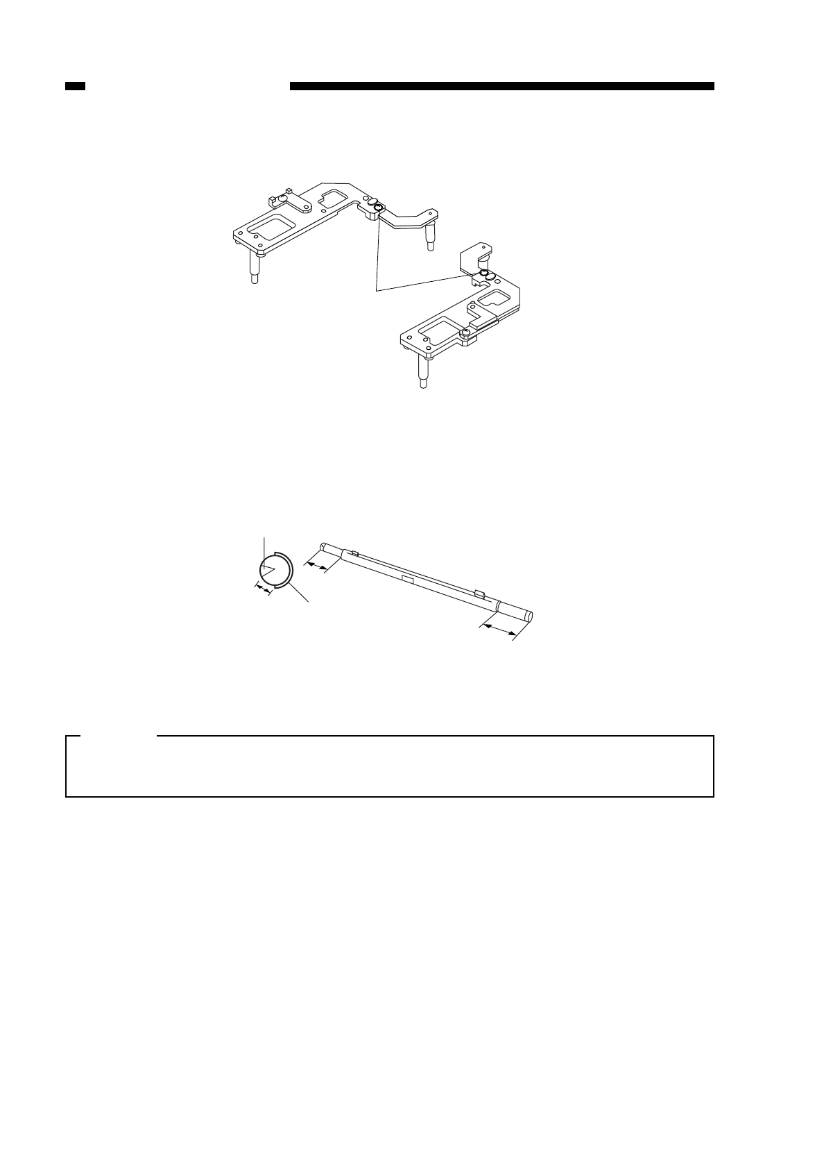
4) Tighten the screw.
Figure 10-218
5. Points to Note When Attaching the Fluorescent Lamp Heater/Scanning Lamp
• Attach the heater to the lamp as follows:
Figure 10-219
Caution:
Do not touch the fluorescent lamp. (Use lint-free paper.)
Do not block the light-emitting portion by the fluorescent lamp heater.
10-18
CHAPTER 10 TROUBLESHOOTING
COPYRIGHT
©
1997 CANON INC. CANON NP6218 REV. 0 MAY 1997 PRINTED IN JAPAN (IMPRIME AU JAPON)
A
A
B
B
Position A
Light-
emitting
portion
Fluorescent
heater
1~5mm
60mm 60mm
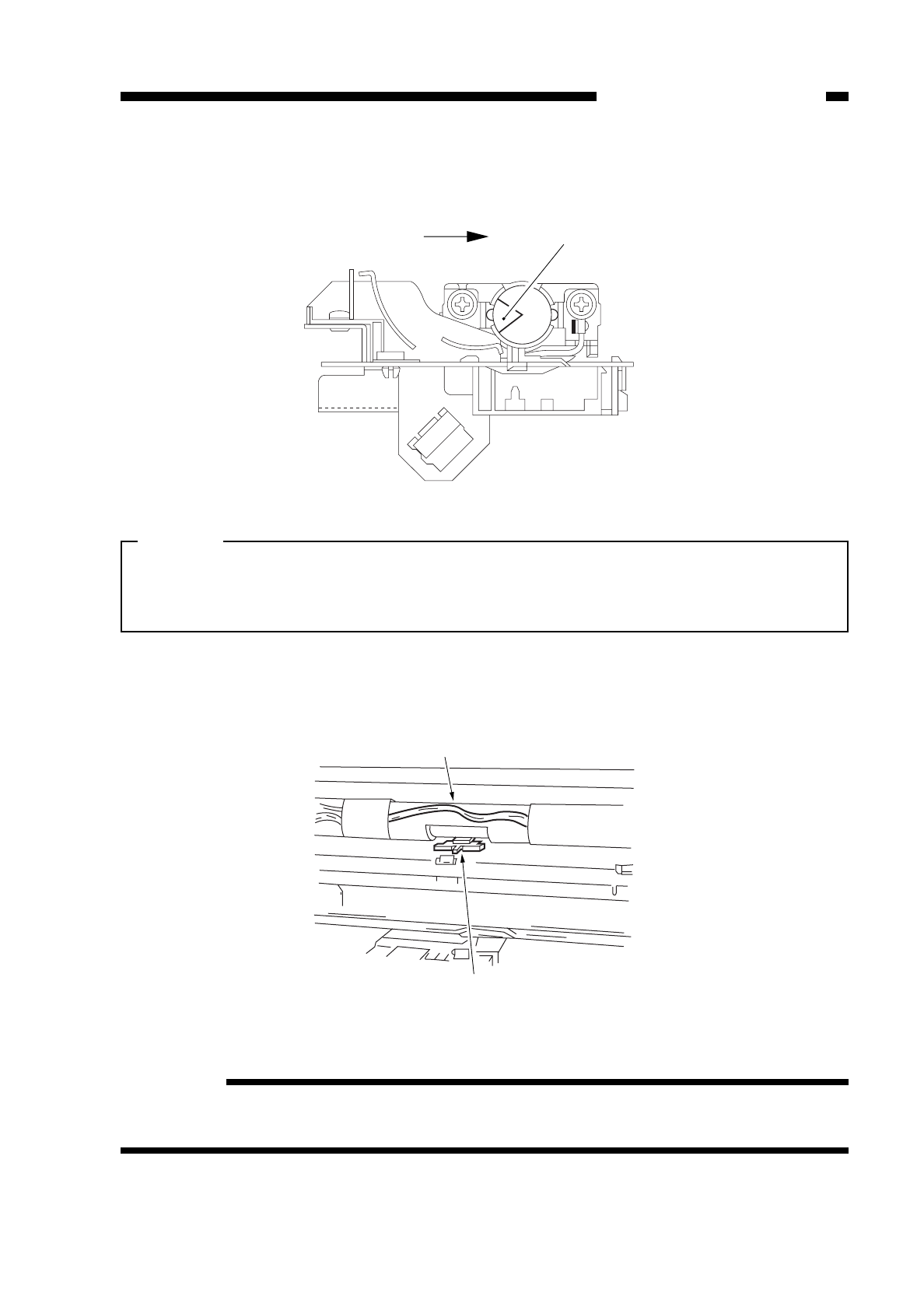
Attach the scanning lamp so that its light-emitting portion (open side) is to the left
when viewed from the front of the copier as shown in Figure 10-220.
Figure 10-220 (front view)
Caution:
Do not touch the fluorescent lamp. (Use rint-free paper)
Be sure to adjust the gain and AE whenever you have replaced the fluorescent
lamp. (See P. 10-11.)
• Make sure that the cut-off of the fluorescent heater is correctly oriented in relation
to the intensity adjustment sensor.
Figure 10-221
Reference:
The fluorescent lamp heater will not operate unless the copier’s heater switch is
turned on.
10-19
CHAPTER 10 TROUBLESHOOTING
COPYRIGHT
©
1997 CANON INC. CANON NP6218 REV. 0 MAY 1997 PRINTED IN JAPAN (IMPRIME AU JAPON)
Light-emitting portion
Light adjustment sensor
Fluorescent lamp heater
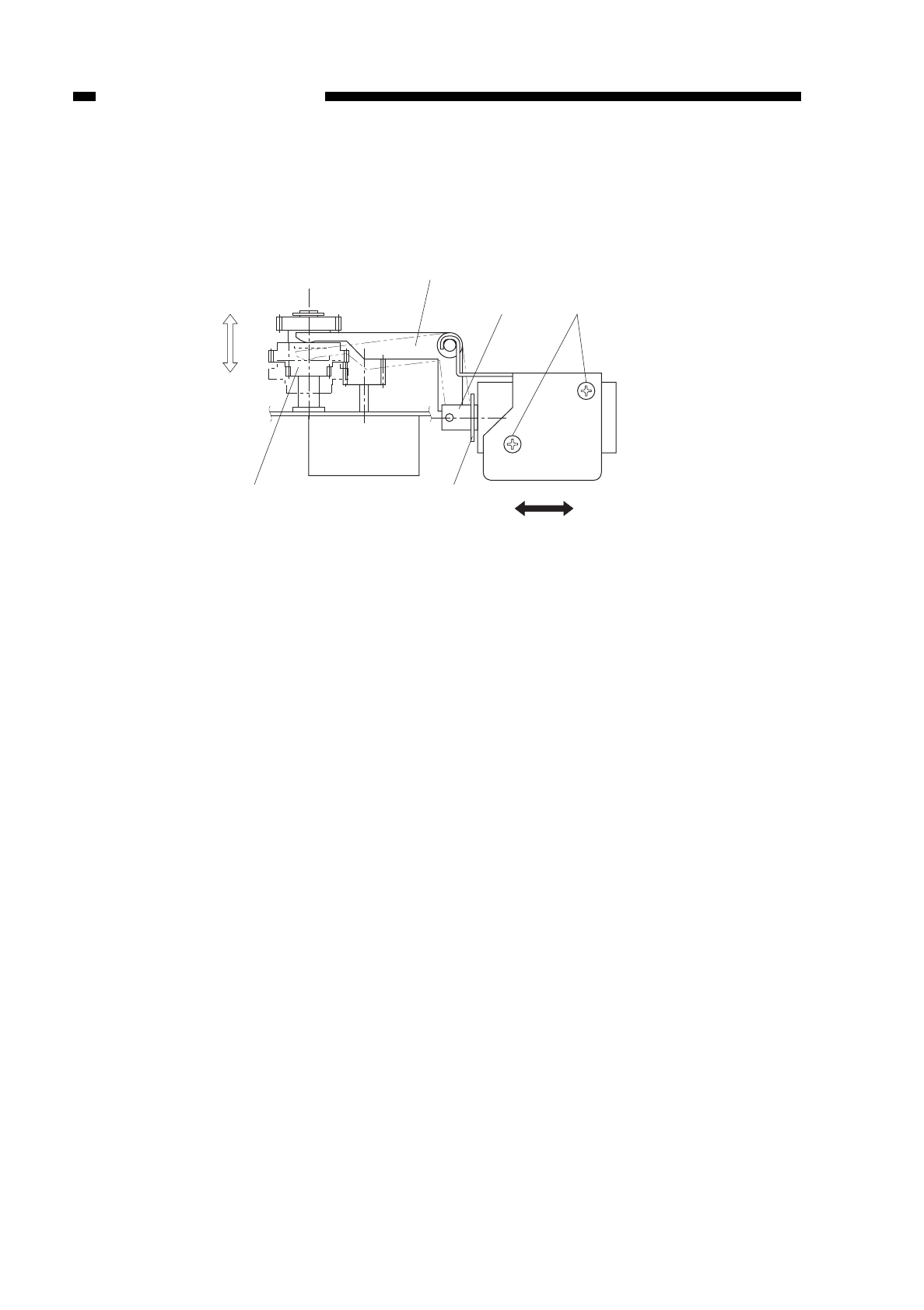
6. Positioning the Change Solenoid
Make adjustments by loosening the two screws tso that the gear rbutts against
the direction of b by the arm ewhen the steel core qof the solenoid is fully pushed in
the direction of B, i.e., when the E-ring comes into contact with the solenoid.
Figure 10-222
10-20
CHAPTER 10 TROUBLESHOOTING
COPYRIGHT
©
1997 CANON INC. CANON NP6218 REV. 0 MAY 1997 PRINTED IN JAPAN (IMPRIME AU JAPON)
t
q
w
e
rAB
a
b
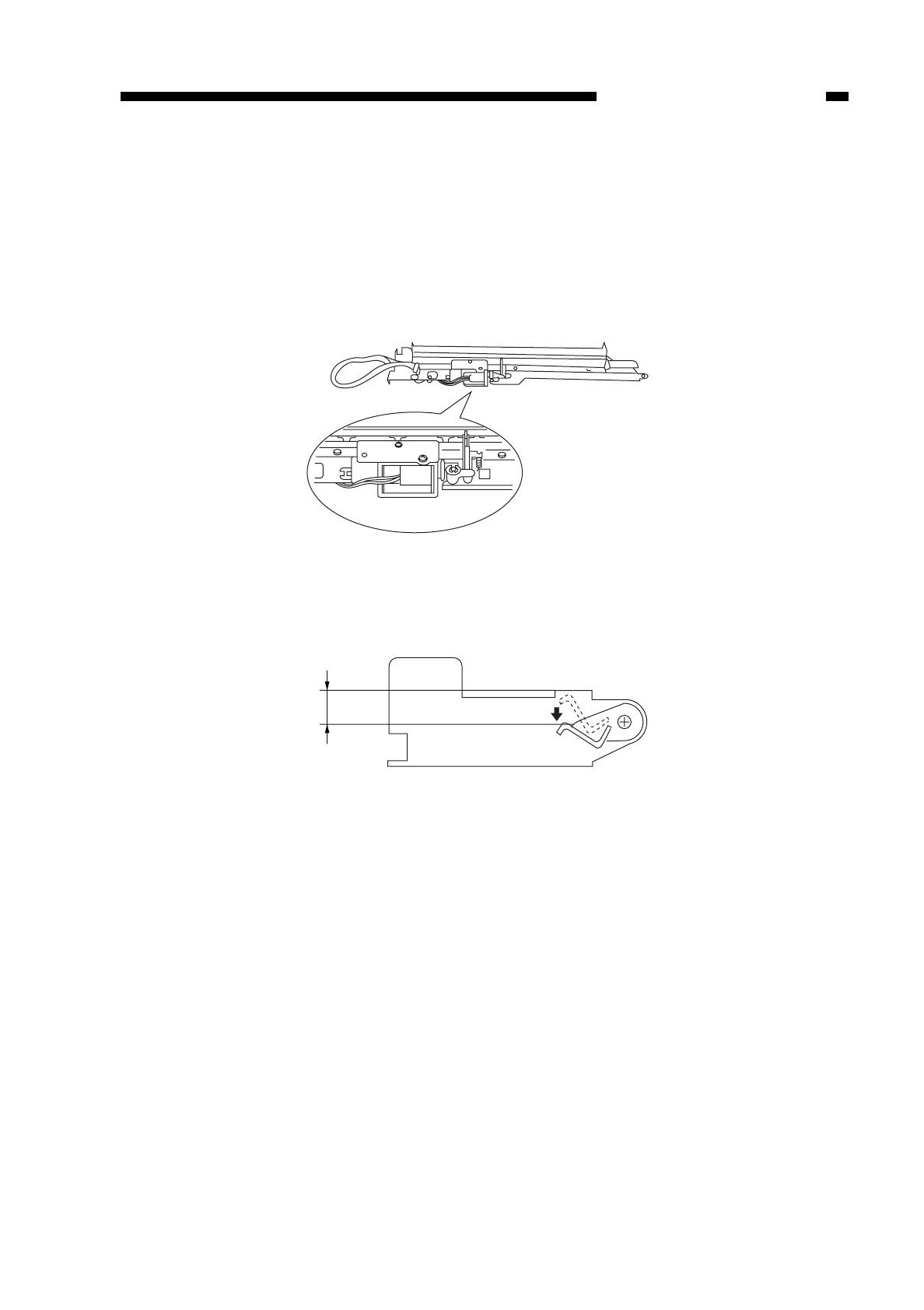
C. Image Formation System
1. Positioning the Blank Shutter Solenoid
Adjust the position of the blank shutter solenoid so that the bottom A is 9.5 ±0.5 mm
on both sides when the solenoid is moved in the direction of ON; try not to force down
the shutter.
After adjustments, make sure that the solenoid moves smoothly.
Figure 10-223a
Figure 10-223b
10-21
CHAPTER 10 TROUBLESHOOTING
COPYRIGHT
©
1997 CANON INC. CANON NP6218 REV. 0 MAY 1997 PRINTED IN JAPAN (IMPRIME AU JAPON)
A
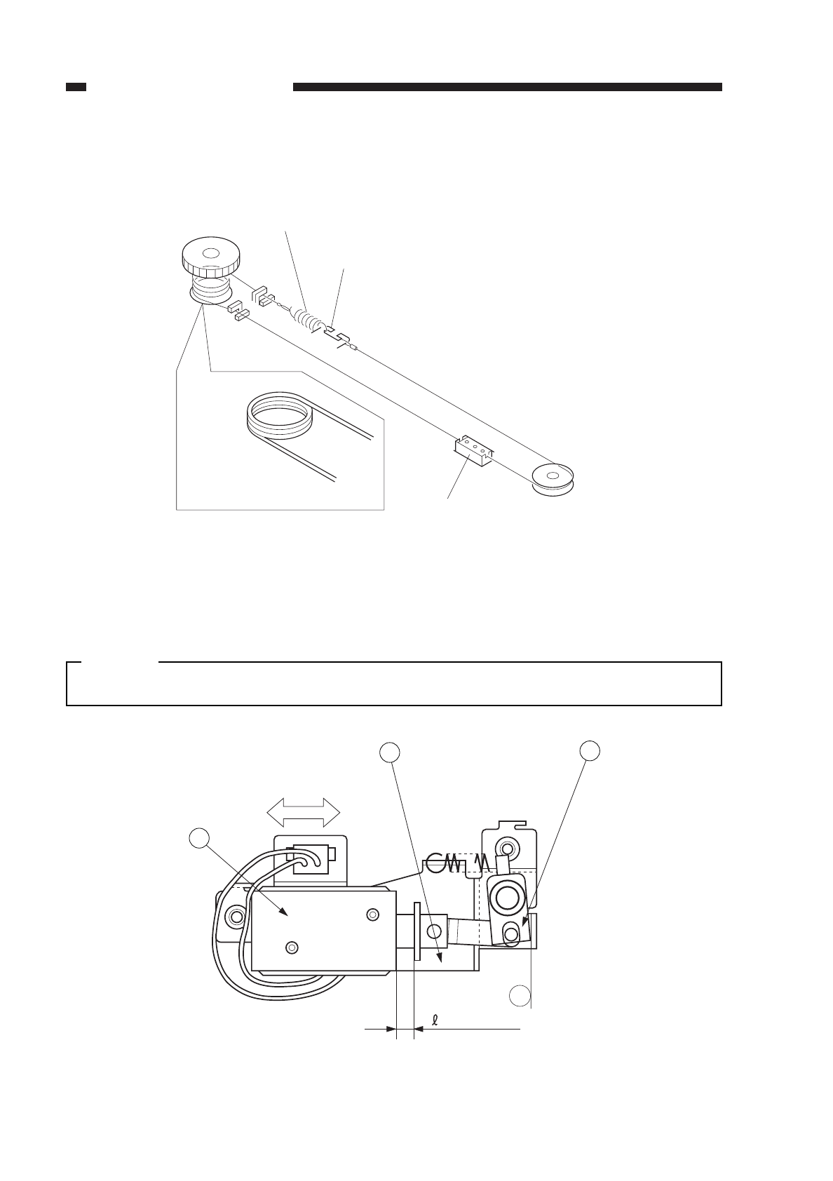
2. Routing the Blank Shutter Cable
Figure 10-224
3. Positioning the Solenoid for the Primary Charging Roller
Loosen the two screws used to fix the solenoid ein place, and move the solenoid in
the direction of B so that the
Rin Figure 10-225 is 5.5 ±0.2 mm when the joint qis
butted against a of the solenoid support plate w.
Caution:
Be sure to make the adjustment whenever you have replaced the solenoid.
Figure 10-225
10-22
CHAPTER 10 TROUBLESHOOTING
COPYRIGHT
©
1997 CANON INC. CANON NP6218 REV. 0 MAY 1997 PRINTED IN JAPAN (IMPRIME AU JAPON)
Attach the spring to
the outside of the
sides shutter.
Slide shutter (rear)
Wind 3.5 times.
Slide shutter (front)
a
= 5.5 ± 0.2
21
3
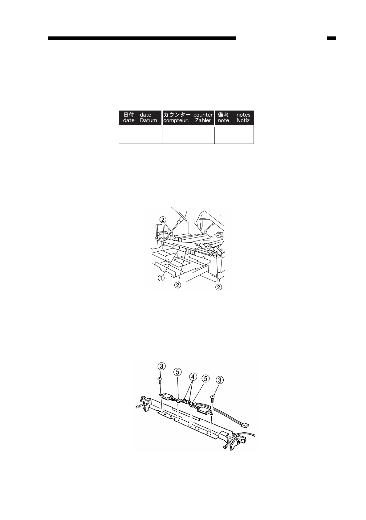
4. After Replacing the Drum Unit
Whenever you have replaced the drum unit, enter the date of replacement and the
current counter reading on the label (Figure 10-226) that came with the drum unit; attach
the label to the front cover of the new drum unit, and perform the image basic adjustment
procedure.
Figure 10-226
5. Attaching the Drum Heater
1) Detach the front cover.
2) Open the copier’s top body by operating the copier open/close lever.
3) Remove the two fixing screws w, and detach the harness cover q.
Figure 10-227
4) Detach the transfer roller and the static eliminator.
5) Detach the transfer guide.
6) Butt the two heaters against the transfer guide as shown in Figure 10-228, and fix the
two mounts with two screws e; further, fix the harness in place using two harness
bands r(front, rear).
Figure 10-228
10-23
CHAPTER 10 TROUBLESHOOTING
COPYRIGHT
©
1997 CANON INC. CANON NP6218 REV. 0 MAY 1997 PRINTED IN JAPAN (IMPRIME AU JAPON)
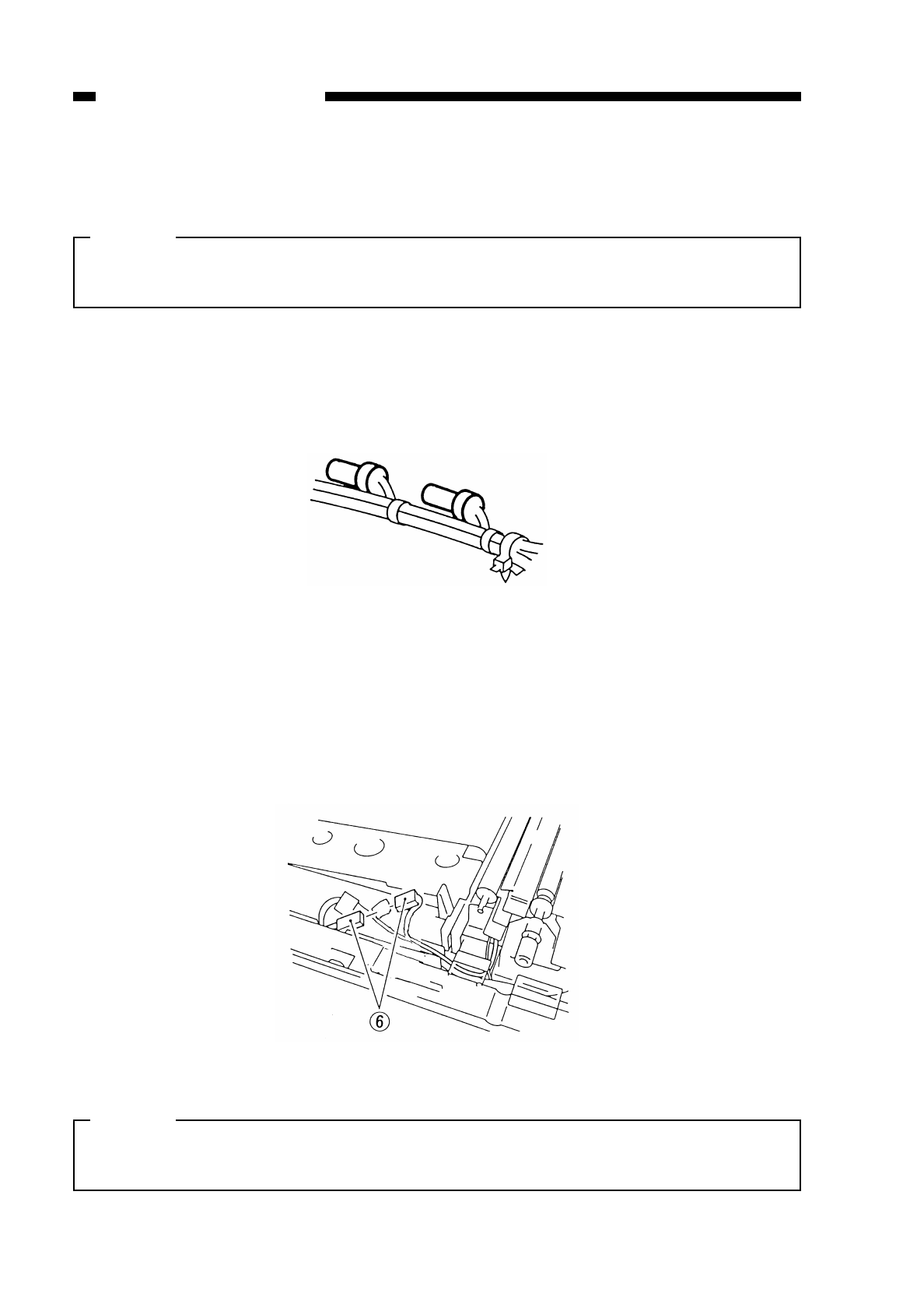
7) Fix the harness in place using two SK binders (WT2-5145; front, rear) t; then, insert
it into the transfer guide.
Caution:
When fixing the harness in place, make sure that the cap portions of the terminals
alternate; keeping them in parallel will bring them in contact with the transfer roller.
8) Fix the harness with two SK binder t(front, rear) in place, and insert it into the
transfer guide.
Figure 10-229
9) Connect the connector yas shown in Figure 10-230.
Figure 10-230
Caution:
When attaching the transfer guide to the copier after attaching the drum heater,
make sure that the spring at the rear is firmly in the groove.
10-24
CHAPTER 10 TROUBLESHOOTING
COPYRIGHT
©
1997 CANON INC. CANON NP6218 REV. 0 MAY 1997 PRINTED IN JAPAN (IMPRIME AU JAPON)
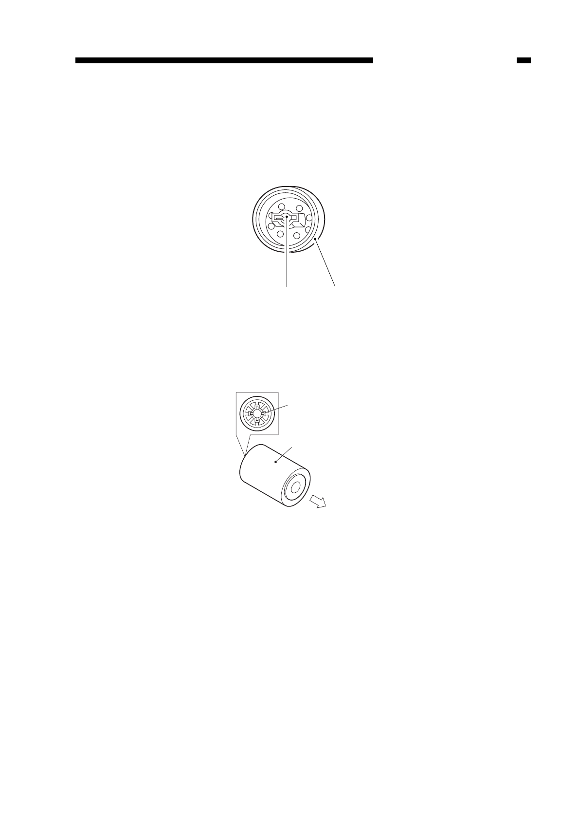
D. Pick-Up/Feeding System
1. Orientation of the Pick-Up Roller
Attach the pick-up roll qso that the side wshown in Figure 10-231 is toward the
rear.
Figure 10-231
2. Orientation of the Multifeeder Pick-Up Roller
Attach the multifeeder pick-up roller qso that the side with the collar with a cross w
is toward the rear.
Figure 10-232
10-25
CHAPTER 10 TROUBLESHOOTING
COPYRIGHT
©
1997 CANON INC. CANON NP6218 REV. 0 MAY 1997 PRINTED IN JAPAN (IMPRIME AU JAPON)
wq
(front)
q
w
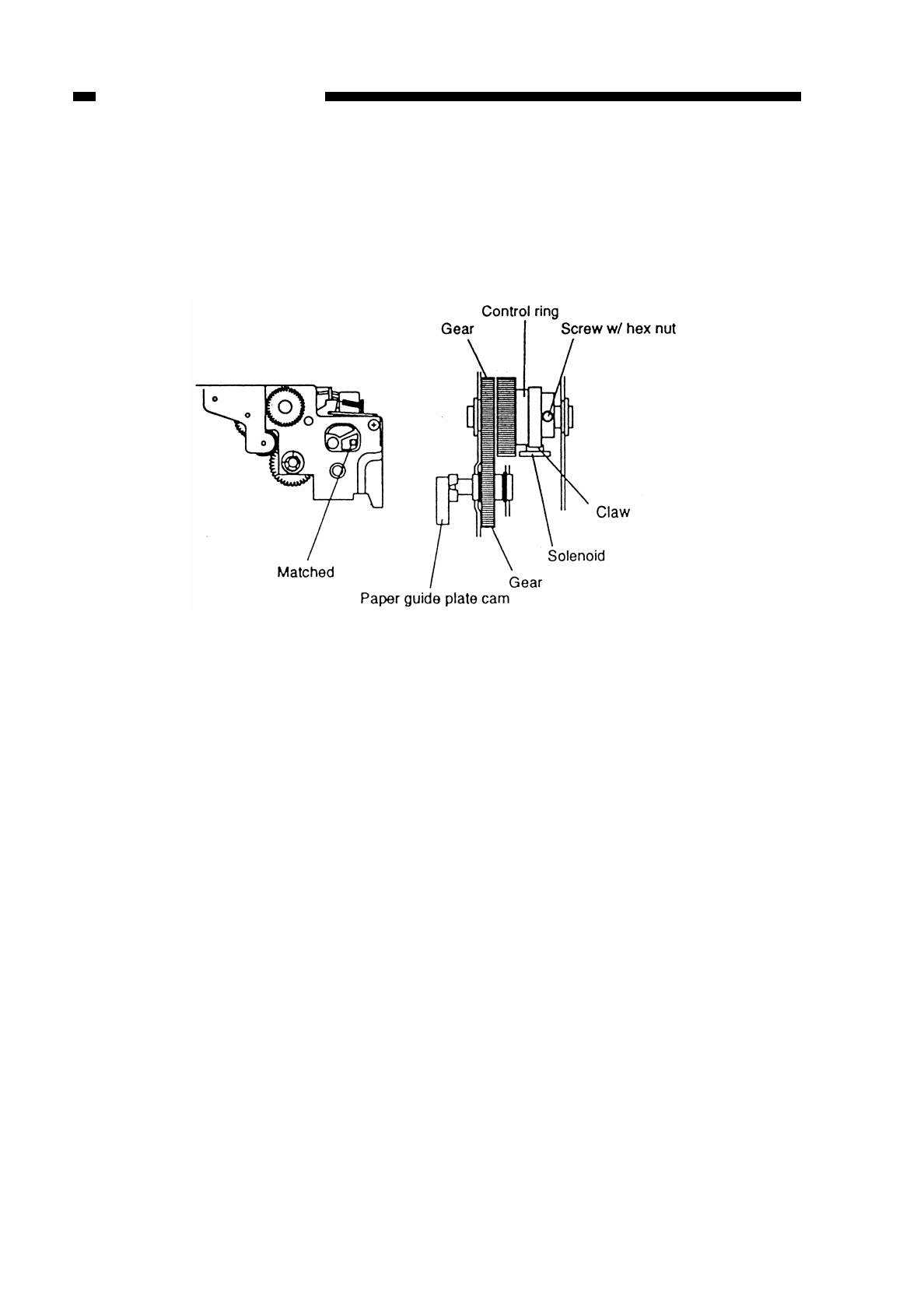
3. Positioning the Paper Guide Plate Cam (multifeeder)
Temporarily fix the screw with a hex nut of the spring clutch assembly in place; turn
the control ring. Make adjustments so that the hole in the cam and the hole in the
multifeeder drive unit match as indicated in Figure 10-233 when the claw of the control
ring is engaged with the solenoid; then, fix in place.
Figure 10-233
10-26
CHAPTER 10 TROUBLESHOOTING
COPYRIGHT
©
1997 CANON INC. CANON NP6218 REV. 0 MAY 1997 PRINTED IN JAPAN (IMPRIME AU JAPON)
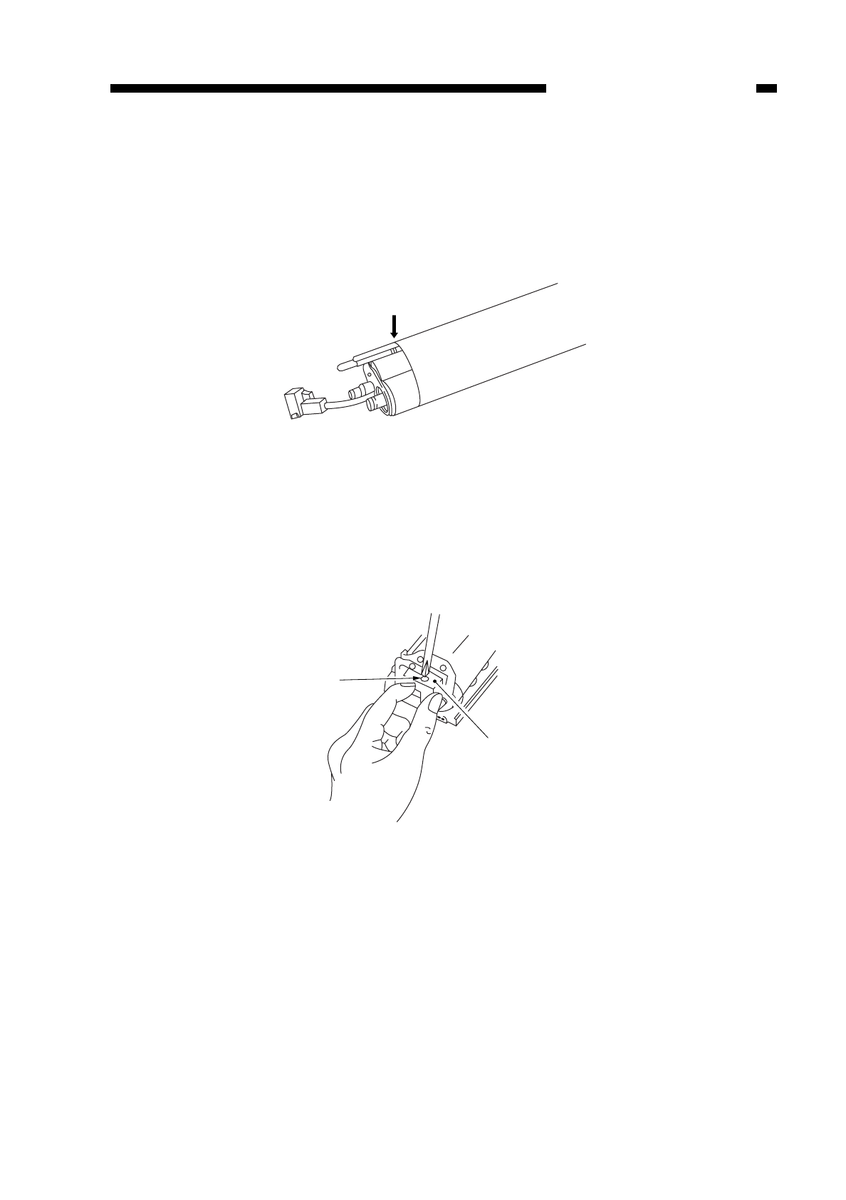
E. Fixing System
1. Points to Note When Attaching the Fixing Film
Orient it so that the cut-off is toward the rear.
Make sure that the end toward the front is along the middle groove.
Figure 10-234
2. Points to Note When Attaching the Heater Connector
• When attaching the heater connector to the fixing heater, take care not to damage
the heater.
• When tightening the screw, hold the connector making sure that both its top and
bottom are free of pressure; do not tighten the screw excessively.
Figure 10-235
10-27
CHAPTER 10 TROUBLESHOOTING
COPYRIGHT
©
1997 CANON INC. CANON NP6218 REV. 0 MAY 1997 PRINTED IN JAPAN (IMPRIME AU JAPON)
Film end aligned.
Screw
Heater connector
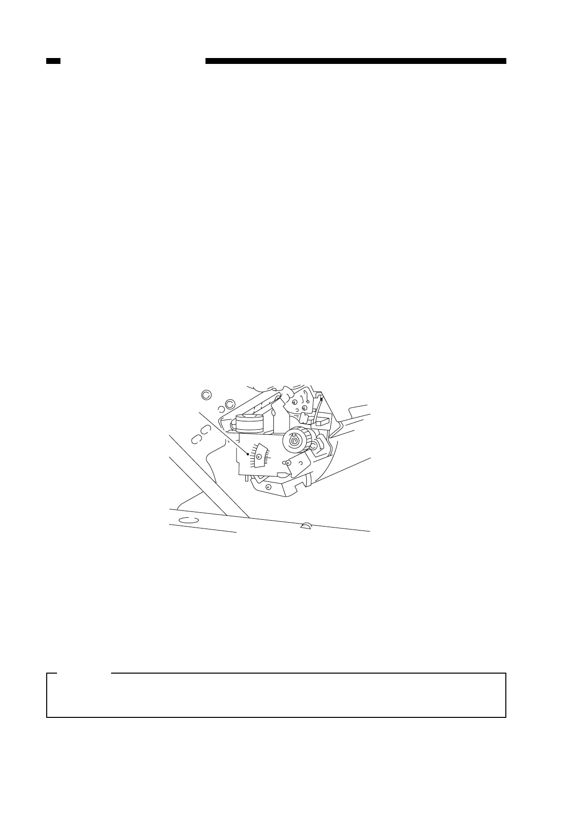
3. Adjusting the Fixing Film Drive Roller Pressure
If a fixing fault occurs, be sure to go through the following to adjust the pressure of
the drive roller.
1) Detach the fixing cover.
2) Detach the inside cover of the copier’s front side.
3) Close the copier’s upper body, and insert the door switch actuator.
4) Press the service mode switch (SW302).
• The copier enters service mode, and the display indicates ‘1’.
5) Press ‘4’ on the keypad.
• The display indicates ‘4’.
6) Press the AE key.
• The copier enters operation check mode, and the display indicates ‘401’.
7) Press ‘5’ on the keypad.
• The display indicates ‘405’.
8) Press the Start key.
• The copier enters fixing film initial rotation mode (405) to return the fixing film to
its proper position.
• The fixing film stops automatically as soon as it reaches its proper position.
• The copier indicates the position of the film in the copy density indicator.
9) Open the copier’s top body.
10) Check that the arrow qis at the middle of the memory as shown in Figure 10-236.
Figure 10-236 (rear view)
11) Close the copier’s top body, and activate service mode.
12) Press ‘4’ on keypad; when the display indicates ‘4’, press the AE key.
13) Press ‘4’ on the keypad; when the display indicates ‘404’, press the Start key.
• The copier enters fixing tension roller mode (404).
• The fixing tension roller becomes fixed, and the fixing film rotates idly.
• The count indicator indicates how long the fixing film sensor has remained on.
Caution:
If the copy count indicator keeps indicating ‘0’ or ‘528’ during adjustment,
immediately press the Stop key to de-activate service mode.
10-28
CHAPTER 10 TROUBLESHOOTING
COPYRIGHT
©
1997 CANON INC. CANON NP6218 REV. 0 MAY 1997 PRINTED IN JAPAN (IMPRIME AU JAPON)
q
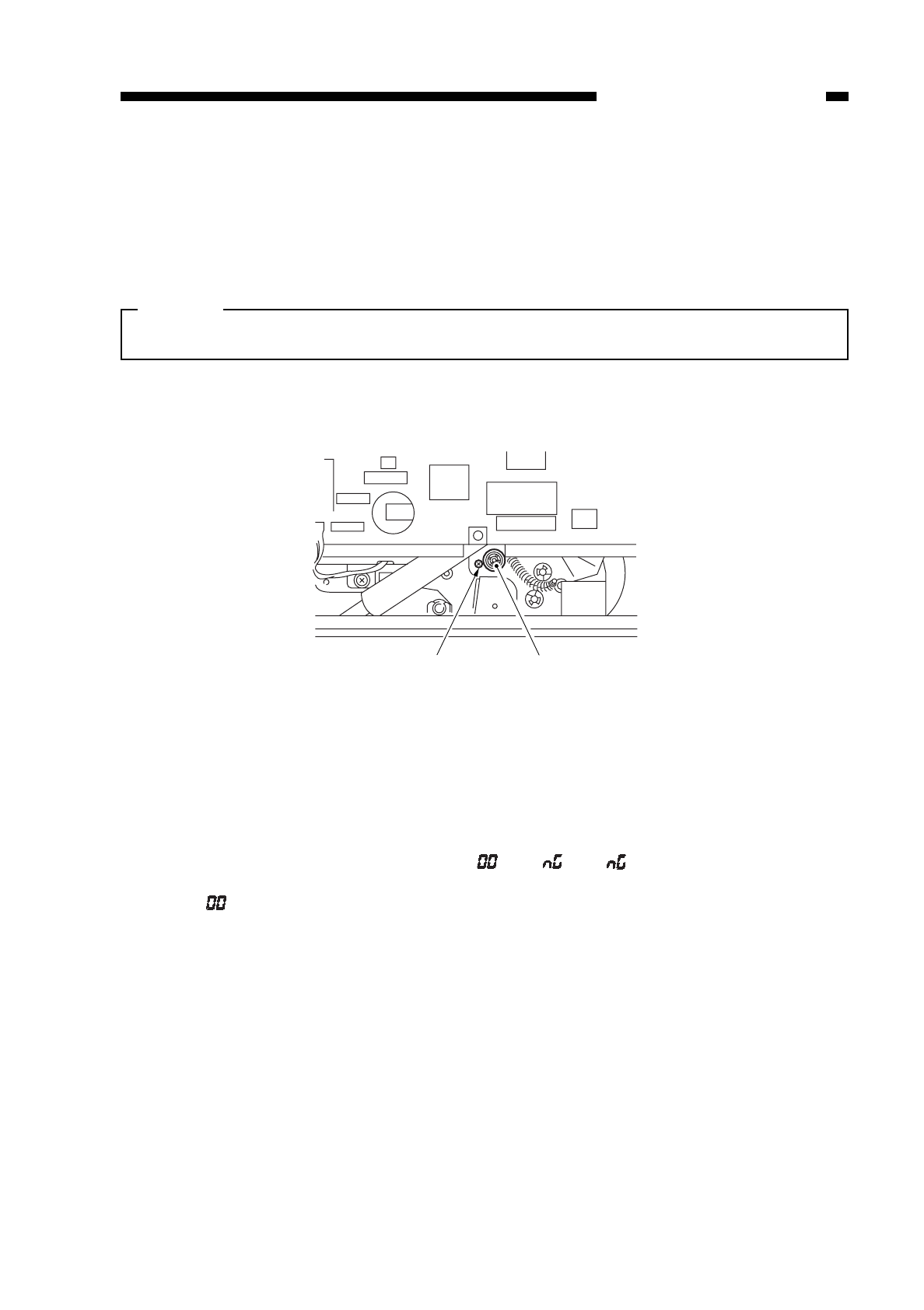
If the copy countis ‘180’ or higher and ‘348’ or lower and has not changed, go to step
17). Or, if 10’s and 100’s do not change, go to step 17);
14) Loosen the fixing screw wslightly; i.e., move it to the left about 1 mm.
15) Turn the adjusting screw eso that the copy count is ‘180’ or higher’ and ‘348’ or
lower.
Caution:
Adjust so that 10’s and 100’s will not change; ignore 1’s may change ±5.)
• A clockwise turn decreases the reading.
• A counterclockwise turn increases the reading.
Figure 10-237
16) When the reading in the copy counter is appropriately correct, tighten the screw w;
make sure that the reading is appropriate after tightening the screw.
17) Press the Start key.
• The copier enters check mode (404), and the fixing film rotates idly for about 2.5
min; check that the fixing film has not shifted from the adjusted position.
• The copy count indicator indicates “ ” or “ ”; if “ ” is indicated, repeat steps
starting with 13).
If “ ” is indicated, repeat steps 4) through 10).
18) Attach the cover.
4. Points to Note after Replacing the Fixing Upper Unit
You must enter the resistance of the heater by selecting ‘No. 304’ in service mode
whenever you have replaced the fixing upper unit. (See p. 10-31.)
10-29
CHAPTER 10 TROUBLESHOOTING
COPYRIGHT
©
1997 CANON INC. CANON NP6218 REV. 0 MAY 1997 PRINTED IN JAPAN (IMPRIME AU JAPON)
e
w
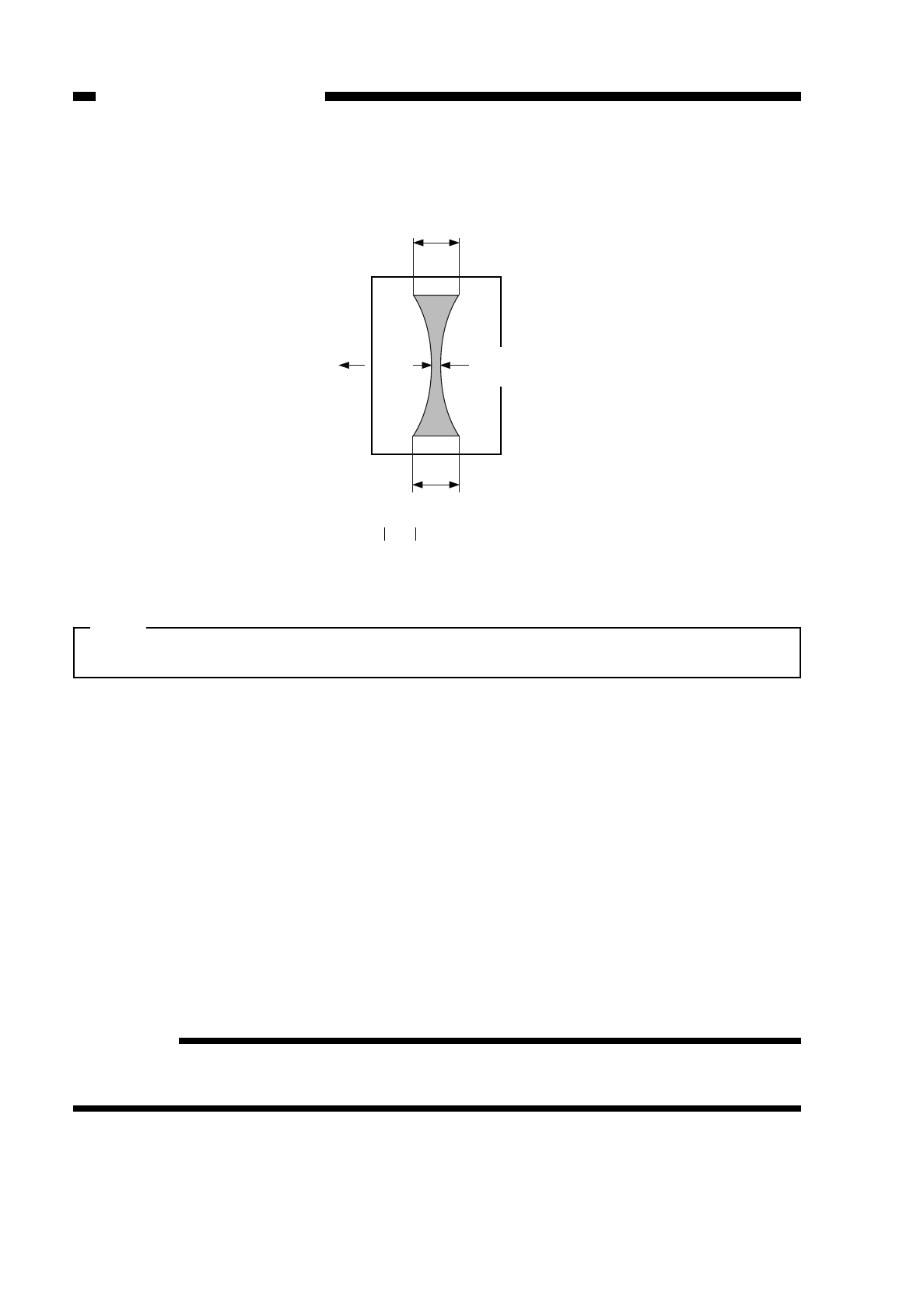
5. Adjusting the Nip
The nip should be as indicated in Figure 10-238. You must make the following
adjustments if fixing faults occur.
Figure 10-238
Note:
a and c represent points 10 cm from both edges of the copy.
a. Measuring the Nip
Measure the nip before starting the day’s work; for example, first thing in the morning.
1) Open the copyboard cover, and make a solid black copy in A4.
2) Place the copy in the multifeeder with the solid black face up.
3) Press the service mode switch (SW302) using a hex key.
• The copier enters service mode, and indicates ‘1’.
4) Press [4] on the keypad.
• The copier indicates ‘4’.
5) Press the AE key.
• The copier enters operation/inspection mode, and indicates ‘401’.
6) Press [6] on the keypad.
• The copier indicates ‘406’.
7) Press the Start key.
• The multifeeder picks up paper, and the copier positions the paper as in Figure
10-238 for measurement, and dischages it.
Reference:
The fixing rollers hold the paper and stop it when half of it has been delivered; the
paper is discharged automatically about 10 sec later.
8) Measure the nip.
10-30
CHAPTER 10 TROUBLESHOOTING
COPYRIGHT
©
1997 CANON INC. CANON NP6218 REV. 0 MAY 1997 PRINTED IN JAPAN (IMPRIME AU JAPON)
c
a
A4
paper
Feeding
direction b
b : 4
-1mm
+2mm
a-c : 1mm or less
Center of copy
paper
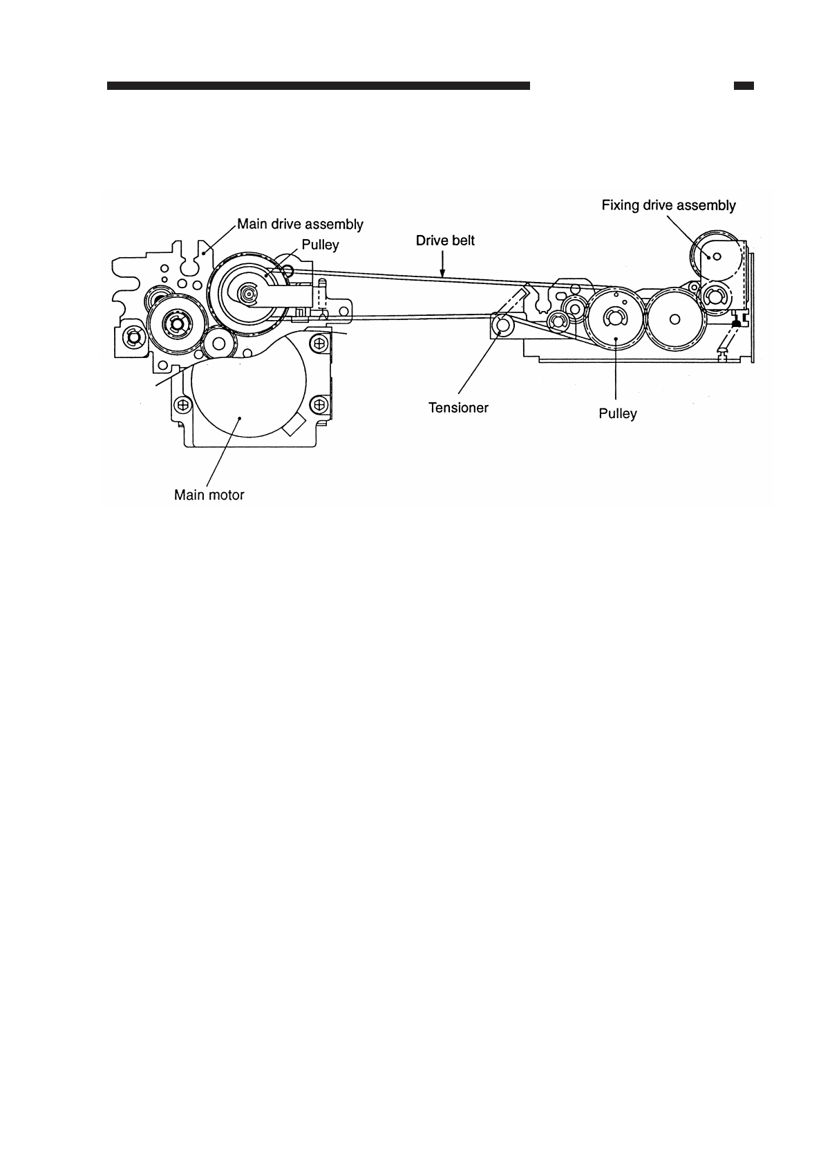
10-31
CHAPTER 10 TROUBLESHOOTING
COPYRIGHT
©
1997 CANON INC. CANON NP6218 REV. 0 MAY 1997 PRINTED IN JAPAN (IMPRIME AU JAPON)
6. Routing the Drive Belt
Route the drive belt around the pulley and tensioner as shown in Figure 10-239.
Figure 10-239
7. Storing the Fixing Heater Resistance
You must store the resistance of the fixing heater as follows whenever you are
replacing the fixing upper unit; do not change the setting unless you have replaced the
heater.
1) Take notes of the resistance (ohm) of the fixing heater recorded on the rear side plate
of the fixing upper unit.
2) Attach the fixing upper unit to the copier.
3) Open the front door, and insert the door switch actuator into the door switch.
4) Press the service mode switch (SW302) with a hex key.
• The copier activates service mode, and indicates ‘1’.
5) Press [3] on the keypad.
• The copier activates adjustment mode, and indicates ‘3’.
6) Press the AE key.
• The copier enters adjustment mode, and indicates ‘301’.
7) Press [0] and [4] on the keypad.
• The copier indicates ‘304’.
8) Press the Start key.
• The copier indicates the current setting.
9) Enter the measured reading, and press the AE key to store.
10) Record the new setting on the service mode label.
11) Press the Reset key.
• The copier de-activates service mode.
unit: ohms; enter a value which is the result of the measured resistance multiplied
by 10.
range (default)
220/240V: ..........235 to 325 (280)
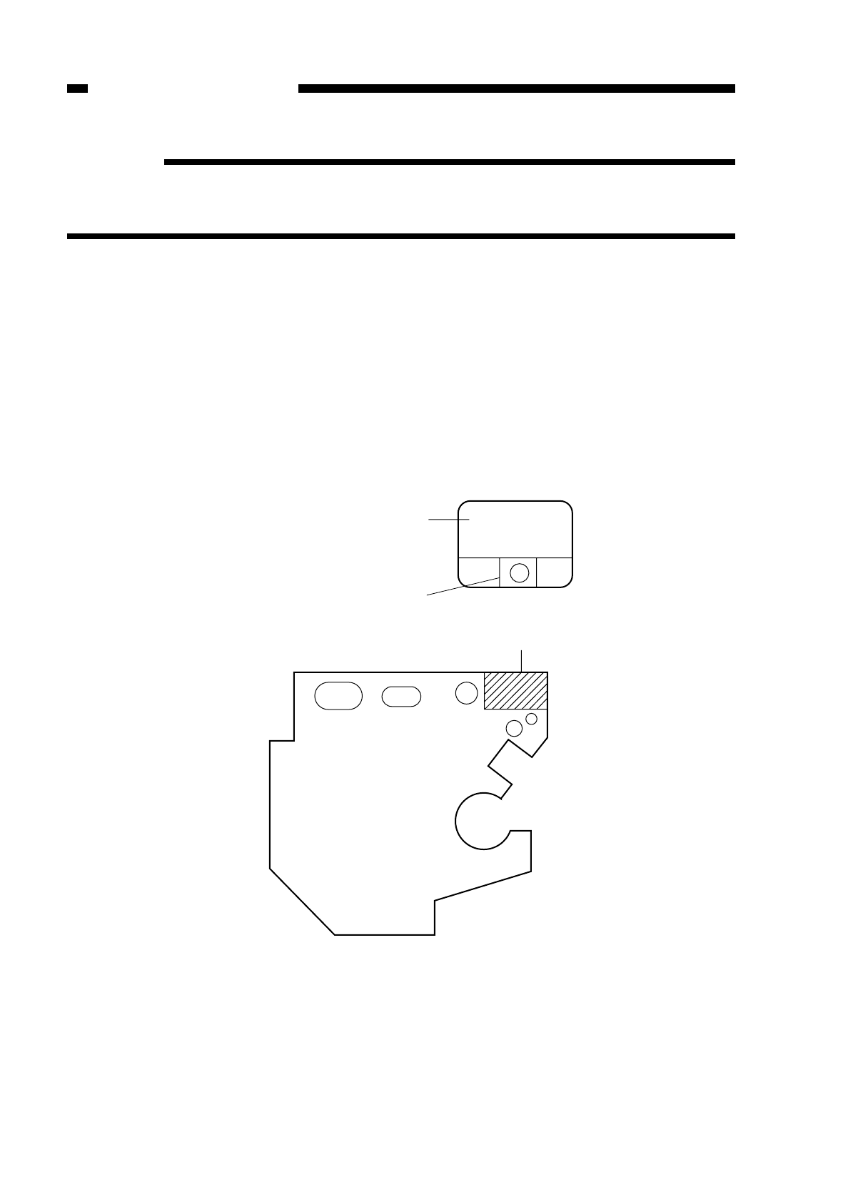
Reference:
1. If the measured resistance is 9.5 ohms, enter ‘095’; if 28 ohms, enter ‘280’.
2. The power supplied to the fixing heater is phase-controlled based on the voltage of
the power supply and the resistance being stored.
8. Setting the Fixing Heater Temperature Control Value
You can change the fixing temperature control value in the field in any of the following
two ways:
8-1 When Replacing the Fixing Upper Unit
Set the initial control temperature value for the 1st to 4th copies under No. 508 of
service mode for when the temperature of the fixing heater is less than 120°C at time
copying is started.
1) Take notes of the value recorded on the label on the fixing upper unit heater stay
(rear).
Figure 10-240 Heater Stay Side Plate (rear)
10-32
CHAPTER 10 TROUBLESHOOTING
COPYRIGHT
©
1997 CANON INC. CANON NP6218 REV. 0 MAY 1997 PRINTED IN JAPAN (IMPRIME AU JAPON)
Label
3-digit resistance to be entered in
service mode No. 304
Fixing temperature control value
to be entered in service mode No.508
Label location
123

2) Replace the fixing upper unit.
3) Press the service switch (SW302).
• The copier enters service mode and indicates ‘1’.
4) Enter ‘5’ using the keypad.
• The display indicates ‘5’.
5) Press the AE key, and enter ‘8’ on the keypad.
• The display indicates ‘508’.
6) Press the Start key.
• The display indicates ‘001’, ‘002’, or ‘003’.
7) Enter the control value you have recorded in step 1) using the keypad.
Example:
If the value recorded on the heater stay (rear) of the fixing upper unit is ‘2’,
a.Enter ‘2’ using the keypad to change the value.
b.Press the AE key.
c.Press the Reset key.
Caution:
You must set the resistance of the heater also when replacing the fixing upper unit.
8-2 When Replacing the Fixing Film
1) Replace the fixing film.
2) Replace the copy paper in the cassette with A3 size copy paper.
3) Press the service switch (SW302).
• The copier enters service mode and indicates ‘1’.
4) Enter ‘5’ using the keypad, and press the AE key.
• The display indicates ‘501’.
5) Enter ‘5’ using the keypad, and press the Start key.
• The display indicates ‘001’, ‘002’, or ‘003’.
6) Enter ‘2’ using the keypad, and press the Clear key.
8) Make 20 copies or more in A3 to warm up the entire fixing upper unit.
9) Place the Test Chart NA-3 on the copyboard, and put a blank sheet of paper (A3) to
cover about 2/3 of the Test Chart (bottom).
Figure 10-241
10-33
CHAPTER 10 TROUBLESHOOTING
COPYRIGHT
©
1997 CANON INC. CANON NP6218 REV. 0 MAY 1997 PRINTED IN JAPAN (IMPRIME AU JAPON)
Blank
sheet of
paper
(A3)
Test Chart

COPYRIGHT
©
1997 CANON INC. CANON NP6218 REV. 0 MAY 1997 PRINTED IN JAPAN (IMPRIME AU JAPON)
CHAPTER 10 TROUBLESHOOTING
10-34
10) Enter ‘4’ using the keypad, and set the copy count.
11) Press the service switch (SW302), thereby recalling the temperature of the No. 1
thermistor.
• The display indicates ‘1’.
12) Press the AE key, and enter ‘9’ on the keypad.
• The display indicates ‘109’.
13) Press the Start key.
• Make 4 copies in A3.
14) When copying is finished, take note of the temperature reading in the display. Press
the Start key once again when the reading is 116°–118°C.
• Make four copies in A3.
15) Check if offset has occurred.
• If offset is noted, change the temperature control value of the fixing heater. Go to
step 16).
• If offset is not noted, go to step 21).
16) Press the Clear key, and enter ‘5’ using the keypad.
• The display indicates ‘508’.
17) Press the AE key, and enter ‘8’ using the keypad.
• The display indicates ‘508’.
18) Press the Start key.
• The display indicates ‘002’.
19) Enter ‘3’ using the keypad.
• The display indicates ‘003’.
20) Press the AE key.
• The setting is changed.
21) Press the Reset key.
• The copier leaves service mode.

F. Electrical
1. After Replacing the PCB
You must make the adjustments that follow whenever you have replaced the following
PCBs.
a. DC Controller PCB
1) Enter the value recorded on the service mode label attached behind the front door in
service mode (‘3’; see p. 10-102).
2) Adjust the multifeeder paper width sensor; see p. 10-43.
3) Adjust the intensity of the scanning lamp; see p. 10-10.
4) Adjust AE; see p. 10-11.
As necessary, change the settings in service mode and user mode.
Caution:
Be sure to record all new settings that you have entered.
b. Composite Power Supply PCB
1) Enter the values recorded on the label attached to the composite power supply in
service mode (‘No. 315’ through ‘No. 318’; ‘3’ of adjustment mode); see p. 10-103.
Be sure to record any new settings on the service mode label.
c. AE Sensor PCB
1) Adjust AE; see p. 10-11.
Caution:
Be sure to record all new settings that you have entered.
d. Intensity Sensor PCB
1) Adjust the intensity of the scanner lamp; see p. 10-10.
2) Adjust AE; see p. 10-11.
Caution:
Be sure to record all new settings that you have entered.
2. Clearing the Back-Up RAM
1) Open the front door, and insert the door switch activator into the door switch.
2) Press the service mode switch (SW302) with a hex key.
• The copier activates service mode, and indicates ‘1’.
3) Press [4] on the keypad.
• The copier indicates ‘4’.
4) Press the AE key.
• The copier activates operation/inspection mode, and indicates ‘401’.
5) Press [5] and [0] on the keypad.
• The copier indicates ‘450’.
6) Press the Start key.
• The copier indicates ‘noP’.
10-35
CHAPTER 10 TROUBLESHOOTING
COPYRIGHT
©
1997 CANON INC. CANON NP6218 REV. 0 MAY 1997 PRINTED IN JAPAN (IMPRIME AU JAPON)

7) Press the AE key.
• The indication changes to ‘EE’.
8) Press the Start key.
• The indication returns to ‘450’.
9) Turn off and on the power switch.
• The copier clears the backup RAM, and returns the default settings.
Reference:
To cancel RAM clearing, press the Clear key and then the Reset key. To cancel it
after having finished step 8), press the Start key once again; when ‘noP’ is
indicated, press the Start key once again.
3. Checking the Photointerrupters
The copier allows checking the photointerrupters with a conventional meter or in
service mode.
a. Using a Meter
1) Set the meter to the 12VDC range.
2) Connect the (–) probe of the meter to J301-4 (GND) on the DC controller.
3) Make checks as indicated.
1: 5V
0: 0V
Reference:
All photointerrupters except PS1, PS2, PS3, PS6, and PS9 are connected in the
form of a matrix, and for this reason may show variations if checked by a meter; use
service mode for these photointerrupters.
b. Using Service Mode
1) Open the front door, and insert a door switch actuator into the door switch.
2) Press the service mode switch (SW302) with a hex key.
3) Press [2] on the keypad.
• The copier indicates ‘2’.
4) Press the AE key.
• The copier activates I/O display mode, and indicates ‘201’.
5) Enter a number with the keypad, and press the Start key.
• The copier checks each photointerrupter; see the copy count indicator.
Figure 10-242
10-36
CHAPTER 10 TROUBLESHOOTING
COPYRIGHT
©
1997 CANON INC. CANON NP6218 REV. 0 MAY 1997 PRINTED IN JAPAN (IMPRIME AU JAPON)
2-a 1-a
2-f 2-b
2-g
2-e 2-c
2-d
1-f
1-g
1-b
1-e
1-d
1-c

a. Copier
Name
PS1
Scanner home
position sensor
(SCHP)
PS2
Lens home
reposition
sensor (LHP)
PS3
Blank shutter
home position
sensor (BSHP)
PS4
Cassette paper
sensor (CPD*)
PS5
Multifeeder
paper sensor
(MFPD*)
PS6
Registration
sensor (RPD)
PS7
Separation
sensor (SPD*)
+ probe
Service mode
J311-2
—
J307-2
No. 205 1-c
J315-2
No. 205 1-d
J313-9
No. 205 1-c
J313-3
No. 204 1-d
J314-2
No. 205 1-a
J314-6
No. 204 1-b
Move the
scanner by
hand while
in standby.
Move the
lens mount
by hand while
in standby.
Detach the
blank expo-
sure assem-
bly; do not
disconnect
J315. Move
the blank
shutter.
Slide out
the cassette
while in
standby.
Place paper
on the
multifeeder
tray while in
standby.
Open the
right door
while in
standby, and
insert paper
along the
paper guide
plate.
Move the
detection
lever with a
finger while
in standby.
Checks
The scanner is at
home position.
The scanner is not
at home reposition.
The light-blocking
plate is present.
The light-blocking
plate is not present.
The light-blocking
plate is present.
The light-blocking
plate is not present.
The cassette is slid
out.
The cassette with
paper is slid in.
Paper is placed.
Paper is not placed.
Paper is inserted.
Paper is not
inserted.
The lever is moved.
The lever is not
moved.
Display
indication
1
0
1
0
1
0
0
1
0
1
1
0
0
1
Voltage
reading
on meter
5V
0V
5V
0V
5V
0V
—
—
—
—
5V
0V
—
—
10-37
CHAPTER 10 TROUBLESHOOTING
COPYRIGHT
©
1997 CANON INC. CANON NP6218 REV. 0 MAY 1997 PRINTED IN JAPAN (IMPRIME AU JAPON)

10-38
CHAPTER 10 TROUBLESHOOTING
COPYRIGHT
©
1997 CANON INC. CANON NP6218 REV. 0 MAY 1997 PRINTED IN JAPAN (IMPRIME AU JAPON)
Name
PS8
Delivery sensor
(DSPD*)
PS9
Fixing film
sensor (FFD)
PS10
Right door
open/closed
sensor (RDOP*)
Q651
Cassette size
sensor 1 (CSZ-1)
Q652
Cassette size
sensor 2 (CSZ-2)
Q653
Cassette size
sensor 3 (CSZ-3)
+ probe
Service mode
J312-2
No. 204 1-g
J304-12
No. 205 1-e
J306-15
No. 204 1-a
J314-8
No. 203 1-e
J314-9
No. 203 1-f
J314-10
No. 203 1-g
Move the
detection
lever with a
finger while
in standby.
Move the
detection
lever with a
finger while
in standby
Open the
right door
while in
standby
Slide out the
cassette
while in
standby, and
move the
detection
lever with a
finger.
Slide out the
cassette
while in
standby, and
move the
detection
lever with a
finger
Slide out the
cassette
while in
standby, and
move the
detection
lever with a
finger.
Checks
The lever is moved.
The lever is not
moved.
The light-blocking
plate is present.
The light-blocking
plate is not present.
The right door is
open.
The right door is
closed.
The lever is moved.
The lever is not
moved.
The lever is moved.
The lever is not
moved.
The lever is moved.
The lever is not
moved.
Display
indication
0
1
1
0
0
1
0
1
0
1
0
1
Voltage
reading
on meter
—
—
5V
0V
—
—
—
—
—
—
—
—

b. Cassette Feeding Unit
10-39
CHAPTER 10 TROUBLESHOOTING
COPYRIGHT
©
1997 CANON INC. CANON NP6218 REV. 0 MAY 1997 PRINTED IN JAPAN (IMPRIME AU JAPON)
Name
Q654
Cassette size
sensor 4 (CSZ-4)
+ probe
Service mode
J314-11
No. 203 2-a
Slide out the
cassette
while in
standby, and
move the
detection
lever with a
finger.
Checks
The lever is moved.
The lever is not
moved.
Display
indication
0
1
Voltage
reading
on meter
—
—
Name
PS1cu
Cassette 2
vertical path
sensor (C2VPD)
PS2cu
Cassette 2
paper sensor
(C2PD*)
Q651-2
Cassette 2 size
sensor 1 (C2SZ-
1)
+ probe
Service mode
J319-A2
No. 204 2-b
J319-A4
No. 204 1-e
J319-B1
No. 201 1-e
Draw out the
cassette 2
while in
standby, and
put copy
paper over
the pick-up
guide plate.
Draw out
the cassette
2 while in
standby.
Draw out the
cassette
while in
standby, and
move the
detecting
lever by a fin-
ger; be sure
to set paper
selection to
cassette 2.
Checks
Copy paper is
inserted.
Copy paper is not
inserted.
The cassette is
drawn out.
The cassette is put
back with paper in
it.
The lever is moved.
The lever is not
moved.
Display
indication
1
0
0
1
0
1
Voltage
reading
on meter
—
—
—
—
—
—

COPYRIGHT
©
1997 CANON INC. CANON NP6218 REV. 0 MAY 1997 PRINTED IN JAPAN (IMPRIME AU JAPON)
CHAPTER 10 TROUBLESHOOTING
10-40
Name
Q652-2
Cassette 2 size
sensor 2 (C2SZ-
2)
Q653-2
Cassette 2 size
sensor 3 (C2SZ-
3)
Q654-2
Cassette 2 size
sensor 4 (C2SZ-
4)
PS3cu
Cassette 3
vertical path
sensor (C3VPD)
+ probe
Service mode
J319-B2
No. 201 1-f
J319-B3
No. 201 1-g
J319-B4
No. 201 2-a
J319-A7
No. 203 1-b
Draw out the
cassette
while in
standby, and
move the
detecting
lever by a fin-
ger; be sure
to set paper
selection to
cassette 2.
Draw out the
cassette
while in
standby, and
move the
detecting
lever by a fin-
ger; be sure
to set paper
selection to
cassette 2.
Draw out the
cassette
while in
standby, and
move the
detecting
lever by a fin-
ger; be sure
to set paper
selection to
cassette 2.
Draw out the
cassette 3
while in
standby, and
put copy
paper over
the pick-up
guide plate.
Checks
The lever is moved.
The lever is not
moved.
The lever is moved.
The lever is not
moved.
The lever is moved.
The lever is not
moved.
Copy paper is
placed.
Copy paper is not
placed.
Display
indication
0
1
0
1
0
1
1
0
Voltage
reading
on meter
—
—
—
—
—
—
—
—

COPYRIGHT
©
1997 CANON INC. CANON NP6218 REV. 0 MAY 1997 PRINTED IN JAPAN (IMPRIME AU JAPON)
CHAPTER 10 TROUBLESHOOTING
10-41
Name
PS4cu
Cassette 3
paper sensor
(C3PD*)
Q651-3
Cassette 3 size
sensor 1 (C3SZ-
1)
Q652-3
Cassette 3 size
sensor 2 (C3SZ-
2)
Q653-3
Cassette 3 size
sensor 3 (C3SZ-
3)
+ probe
Service mode
J319-A9
No. 203 1-f
J319-B1
No. 202 1-e
J319-B2
No. 202 1-f
J319-B3
No. 202 1-g
Draw out
the cassette
3 while in
standby.
Draw out the
cassette
while in
standby, and
move the
detecting
lever by a fin-
ger; be sure
to set paper
selection to
cassette 3.
Draw out the
cassette
while in
standby, and
move the
detecting
lever by a fin-
ger; be sure
to set paper
selection to
cassette 3.
Draw out the
cassette
while in
standby, and
move the
detecting
lever by a fin-
ger; be sure
to set paper
selection to
cassette 3.
Checks
The cassette is
drawn out.
The cassette is
inserted with paper
in it.
The lever is moved.
The lever is not
moved.
The lever is moved.
The lever is not
moved.
The lever is moved.
The lever is not
moved.
Display
indication
0
1
0
1
0
1
0
1
Voltage
reading
on meter
—
—
—
—
—
—
—
—

COPYRIGHT
©
1997 CANON INC. CANON NP6218 REV. 0 MAY 1997 PRINTED IN JAPAN (IMPRIME AU JAPON)
CHAPTER 10 TROUBLESHOOTING
10-42
Name
Q654-4
Cassette 3 size
sensor 4 (C3SZ-
4)
PS5cu
Cassette right
door
open/closed
sensor
(CRDOP*)
+ probe
Service mode
J319-B4
No. 202 2-a
J319-A6
No. 204 2-a
Draw out the
cassette
while in
standby, and
move the
detecting
lever by a fin-
ger; be sure
to set paper
selection to
cassette 3.
Open the
right door
while in
standby.
Checks
The lever is moved.
When the lever is
not moved.
The lever is moved.
The lever is not
moved.
Display
indication
0
1
0
1
Voltage
reading
on meter
—
—
—
—
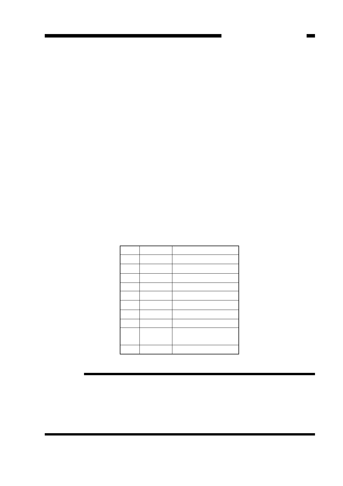
4. Adjusting the Multifeeder Paper Width Sensor
Store the characteristic of the multifeeder paper width sensor in service mode (501).
Perform the adjustment when you have replaced the sensor if the sensor fails to
identify the paper size correctly.
1) Open the front door, and insert the door switch actuator into the door switch.
2) Press the service mode switch (SW302) with a hex key.
• The copier activates service mode, and indicates ‘1’.
3) Press [5] on the keypad.
• The copier indicates ‘5’.
4) Press the AE key.
• The copier activate specification settings mode, and indicates ‘501’.
5) Press the Start key.
• The copier indicates ‘A3’.
6) A press on the keypad changes the indication as shown in Table 10-201. Select the
size of paper to change. (Do not select CLR.)
• The indication will start to flash if you select a size which has not been stored.
• If you press the Start key when ‘CLR’ is indicated, the copier clears all stored settings
and returns the default settings.
7) Shift the guide on the multifeeder to suit the size to be stored.
• Be sure to hear a click.
8) Press the AE key.
• When the setting is stored, the indication stops flashing and remains on.
9) Press the Reset key.
• The copier de-activates service mode.
Table 10-201
Reference:
1. When storing JPC (No. 9), adjust the guide width to the smallest width.
2. At time of shipment, the settings are A3, A4R, and JPC; the copier retains the
characteristics curves of the corresponding three points and uses them when
identifying the size of paper during copying operation. When you store a size other
than these three, the copier takes the new settings into account when making
computations; for this reason, it is best to store sizes that the user tends to use most
frequently.
10-43
CHAPTER 10 TROUBLESHOOTING
COPYRIGHT
©
1997 CANON INC. CANON NP6218 REV. 0 MAY 1997 PRINTED IN JAPAN (IMPRIME AU JAPON)
Remarks
A3
Ledger
B4
Legal
A4R
B5R
A5R
Statement R
Postcard
(100 mm wide)
Clear (Clears settings)
Key
1
2
3
4
5
6
7
8
9
0
Indication
A3
Ldr
b4
LGL
A4r
b5r
A5r
Sr
JPC
CLr
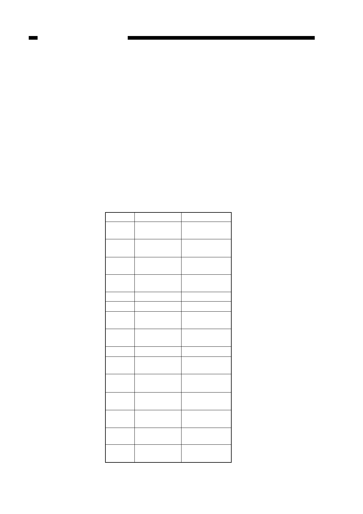
COPYRIGHT
©
1997 CANON INC. CANON NP6218 REV. 0 MAY 1997 PRINTED IN JAPAN (IMPRIME AU JAPON)
CHAPTER 10 TROUBLESHOOTING
10-44
5. Setting the Paper Size for the Universal Cassette
If the paper size lever for the cassette is at the universal cassette, set the appropriate
paper size in service mode (505).
1) Open the front door, and insert the door switch actuator into the door switch.
2) Press the service mode switch (SW302) with a hex key.
• The copier activates service mode, and indicates ‘1’.
3) Press [5] on the keypad.
• The copier indicates ‘5’.
4) Press the AE key.
• The copier enters machine settings mode, and indicates ‘501’.
5) Press [0] and [5] on the keypad.
• The copier indicates ‘505’.
6) Press the Start key.
• The copier indicates the current setting for the universal cassette.
7) Select the size to store using the keypad according to Table 10-202.
8) Press the AE key to store the new setting.
9) Press the Reset key.
• The copier de-activates service mode.
Table 10-202
Size
355.0 x 216.0
340.0 x 220.0
340.0 x 220.0
337.0 x 206.0
330.2 x 215.9
330.0 x 210.0
330.2 x 203.2
320.0 x 220.0
317.0 x 216.0
280.0 x 220.0
268.0 x 190.0
266.7 x 203.2
220.0 x 280.0
203.2 x 266.7
190.0 x 268.0
Keypad
0
1
2
3
4
5
6
7
8
9
10
11
12
13
14
Paper
Bolivian
OFFICIO
Argentine
OFFICIO
Argentine
LEGAL
Australian
FOOLSCAP
FOOLSCAP
FOLIO
Government
LEGAL
Ecuadorian
OFFICIO
OFFICIO
Argentine
LTTER-R
Korean
Government-R
Government
LETTER-R
Argentine
LETTER
Government
LETTER
Korean
Government

CHAPTER 10 TROUBLESHOOTING
10-45
III. TROUBLESHOOTING IMAGE FAULTS
A. Initial Checks
1. Site Environment
a. Make sure that the power supply is as specified (±10%).
b. Avoid high temperature/humidity conditions; near water faucets, water boilers, and
humidifiers. Avoid areas subject to excessively low temperature, sources of fire, and
dust.
c. Avoid areas subject to ammonium gas.
d. Avoid areas subject to direct rays of the sun; otherwise, instruct the user to provide
curtains.
e. Make sure the room is well ventilated.
f. Make sure that the floor will keep the machine level.
Check the site to see if it complies with the above requirements.
2. Checking the Originals
Identify the problem as to whether it is caused by the machine or the original used.
a. Originals with a reddish tinge result in copies with poor contrast; for example, red
sheets and slips.
Reference:
The operation of the following heaters may be controlled by the user by changing
the respective settings; at time of shipment, the settings are at OFF—this means
the copier may remain connected or disconnected at night. If the use of any of the
heaters proves to be necessary because of unique site conditions, the copier
should remain powered at night without disconnecting its power plug.
• fluorescent lamp heater (accessory)
• lens mount heater
• No. 2 mirror mount heater
b. Diazo copies or originals with high transparency can result in copies that can be
mistaken for foggy copies. Originals prepared in pencil can result in copies that can
be mistaken for light copies.
3. Checking the Copyboard Cover and the Copyboard Glass
Check the copyboard cover and the copyboard glass for dirt; if soiled, clean them using
a solution of mild detergent or alcohol; if scratched, replace them.
4. Checking the Paper
a. Check if the paper is Canon-recommended paper.
b. Check if the paper is dry; try paper fresh out of the package.
COPYRIGHT
©
1997 CANON INC. CANON NP6218 REV. 0 MAY 1997 PRINTED IN JAPAN (IMPRIME AU JAPON)

5. Others
Moving a machine which has been cooled in a storage room or the like in winter to
a warm room can lead to condensation inside the machine, causing various problems;
for instance,
a. condensation on the scanning system (glass, mirror, lens) leads to light images.
b. condensation in the charging system leads to electrical leakage.
c. condensation on the pick-up/feeding guide leads to feeding problems.
If condensation is noted, dry wipe the part or leave the machine alone powered for
60 min.
COPYRIGHT
©
1997 CANON INC. CANON NP6218 REV. 0 MAY 1997 PRINTED IN JAPAN (IMPRIME AU JAPON)
10-46
CHAPTER 10 TROUBLESHOOTING

COPYRIGHT
©
1997 CANON INC. CANON NP6218 REV. 0 MAY 1997 PRINTED IN JAPAN (IMPRIME AU JAPON)
10-47
CHAPTER 10 TROUBLESHOOTING

B. SAMPLES OF IMAGE FAULTS
not available
COPYRIGHT
©
1997 CANON INC. CANON NP6218 REV. 0 MAY 1997 PRINTED IN JAPAN (IMPRIME AU JAPON)
10-48
CHAPTER 10 TROUBLESHOOTING

C. Troubleshooting Faulty Images
1. The copy is too light (half-tone only).
COPYRIGHT
©
1997 CANON INC. CANON NP6218 REV. 0 MAY 1997 PRINTED IN JAPAN (IMPRIME AU JAPON)
10-49
CHAPTER 10 TROUBLESHOOTING
Cause
AE mechanism
Developing
assembly
Scanner
Drum cartridge
Checks
Perform the Basic Image
Adjustment Procedure. Is the
problem corrected?
Make copies in AE mode. Is the
density too low, i.e., is the copy
too light?
Is the developing cylinder coated
with a uniform layer of toner?
Clean the mirror, lens, and dust-
proofing glass. Is the problem
corrected?
Step
1
2
3
4
Results
YES
YES
NO
YES
NO
Action
End.
Perform AE adjustment.
Replace the developing
assembly.
End.
Replace the drum
cartridge.
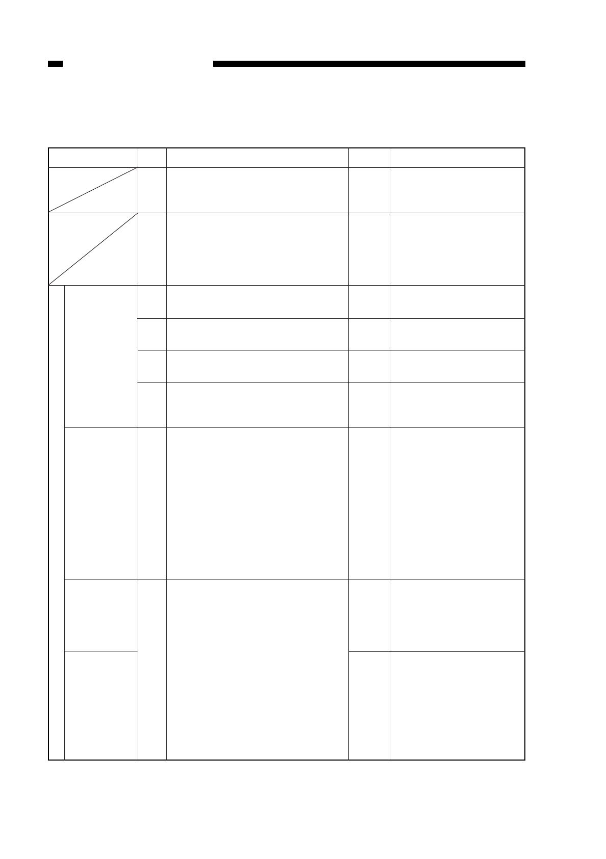
2. The copy is too light (black solid also).
3. The copy is too light (overall, extremely).
COPYRIGHT
©
1997 CANON INC. CANON NP6218 REV. 0 MAY 1997 PRINTED IN JAPAN (IMPRIME AU JAPON)
10-50
CHAPTER 10 TROUBLESHOOTING
Checks
Perform the Image Basic
Adjustment Procedure. Is the
problem corrected?
Turn off the power switch during
copying operation, and open the
front door. Is the toner image on
the photosensitive drum before
transfer more or less normal?
Is the transfer charging roller
securely inserted?
Is electrical leakage noted on the
transfer charging roller?
Is dirt, crack, or scratch noted on
the transfer charging roller?
Are the position and condition of
the pressure spring of the transfer
charging roller normal?
Try fresh copy paper. Is the
problem corrected?
Set the feeding assembly in
feeding position, and measure the
resistance between the lower
transfer guide and the base
(metal) of the transfer charging
assembly rail. Is the resistance 0
Ω?
Cause
Transfer
charging
roller
Copy paper
Lower trans-
fer guide
High-voltage
cord, high-
voltage
transformer,
DC con-
troller PCB
Step
1
2
3
4
5
6
7
8
Results
YES
NO
NO
YES
YES
NO
YES
NO
Action
End.
Go to step 7.
Re-insert the transfer
charging roller.
Check the transfer
charging roller.
Replace the transfer
charging roller.
Correct or replace the
spring.
1. The paper may be
moist; advise the
user on the correct
way of storing paper
2. Advise the user that
the use of paper not
of a type
recommended by
Canon may produce
images falling short
of expectations.
Check if the lower
transfer guide is in
contact with a metal
portion (e.g., side plate
of the feeding assembly).
1. Check the electrical
continuity of the high-
voltage cord.
2. Check the high-
voltage transformer
and the DC controller
PCB.
Transfer

COPYRIGHT
©
1997 CANON INC. CANON NP6218 REV. 0 MAY 1997 PRINTED IN JAPAN (IMPRIME AU JAPON)
10-51
CHAPTER 10 TROUBLESHOOTING
Checks
Take out the developing assembly,
and shake it. Is the problem
corrected?
Is the reading in service mode
(105; primary current) 10 µA or
less?
Cause
Toner level,
toner level
detection
mechanism
Composite
power supply
PCB
Drum cartridge
Step
9
10
Results
YES
YES
NO
Action
The level of toner may
be too low or the toner
level detection
mechanism may be
faulty; advise the user to
replace the toner
cartridge.
Replace the composite
power supply PCB.
Replace the toner
cartridge.
Transfer

4. The copy has uneven density (front too dark).
5. The copy has uneven density (front too light).
COPYRIGHT
©
1997 CANON INC. CANON NP6218 REV. 0 MAY 1997 PRINTED IN JAPAN (IMPRIME AU JAPON)
10-52
CHAPTER 10 TROUBLESHOOTING
Checks
Clean the scanning lamp, reflect-
ing plate, side reflecting plate,
mirror, lens, and dust-proofing
glass. Is the problem corrected?
Execute ‘No. 402’ in service mode
(primary charging roller cleaning).
Is the problem corrected?
Execute ‘No. 403’ in service mode
(transfer roller cleaning). Is the
problem corrected?
Make several blank (white) copies.
Is the problem corrected?
Is the transfer changing roller
securely inserted?
Are the position and condition of
the pressure spring of the transfer
charging roller normal?
Does the pre-exposure lamp turn
on during copying operation?
Is the developing cylinder coated
with a uniform layer of toner?
Cause
Scanner
Primary
charging roller
Transfer charg-
ing assembly
Pre-exposure
lamp
Developing
assembly
Step
1
2
3
4
5
6
7
8
Results
YES
YES
YES
YES
NO
NO
NO
NO
Action
End.
End.
End.
End.
Re-insert the charging
roller.
Corrector replace the
spring.
See “The pre-exposure
lamp fails to turn on.”
Take out the developing
assembly, and shake it
several times; then,
make copies. If the
problem is not corrected,
replace the developing
assembly.

6. The copy is foggy (overall).
COPYRIGHT
©
1997 CANON INC. CANON NP6218 REV. 0 MAY 1997 PRINTED IN JAPAN (IMPRIME AU JAPON)
10-53
CHAPTER 10 TROUBLESHOOTING
Checks
Perform the Basic Image
Adjustment Procedure. Is the
problem corrected?
Clean the scanning lamp, reflect-
ing plate, side reflecting plate,
mirror, lens, and dust-proofing
glass. Is the problem corrected?
Does the pre-exposure lamp turn
on during copying operation?
Is the developing spacer worn?
Is the developing cylinder worn?
Is the developing cylinder
insulated from the copier GND?
Turn off the power supply, and
disconnect J908. Check the
continuity with the meter between
the developing and copier sides of
J908-2.
Is the reading for ‘No. 105’ in
service mode (primary charging
current) 10 µA or less?
Cause
Scanner
Pre-exposure
lamp, DC
controller PCB
Developing
spacer
Developing
cylinder
Developing
cylinder
Drum cartridge
Composite
power supply
PCB
Step
1
2
3
4
5
6
7
Results
YES
YES
NO
YES
YES
NO
NO
YES
Action
End.
End.
See “The pre-exposure
lamp fails to turn on.”
Replace the developing
assembly.
Replace the developing
assembly.
Check the parts around
the developing cylinder
and the developing
connector.
Replace the drum
cartridge.
Replace the composite
power supply PCB.
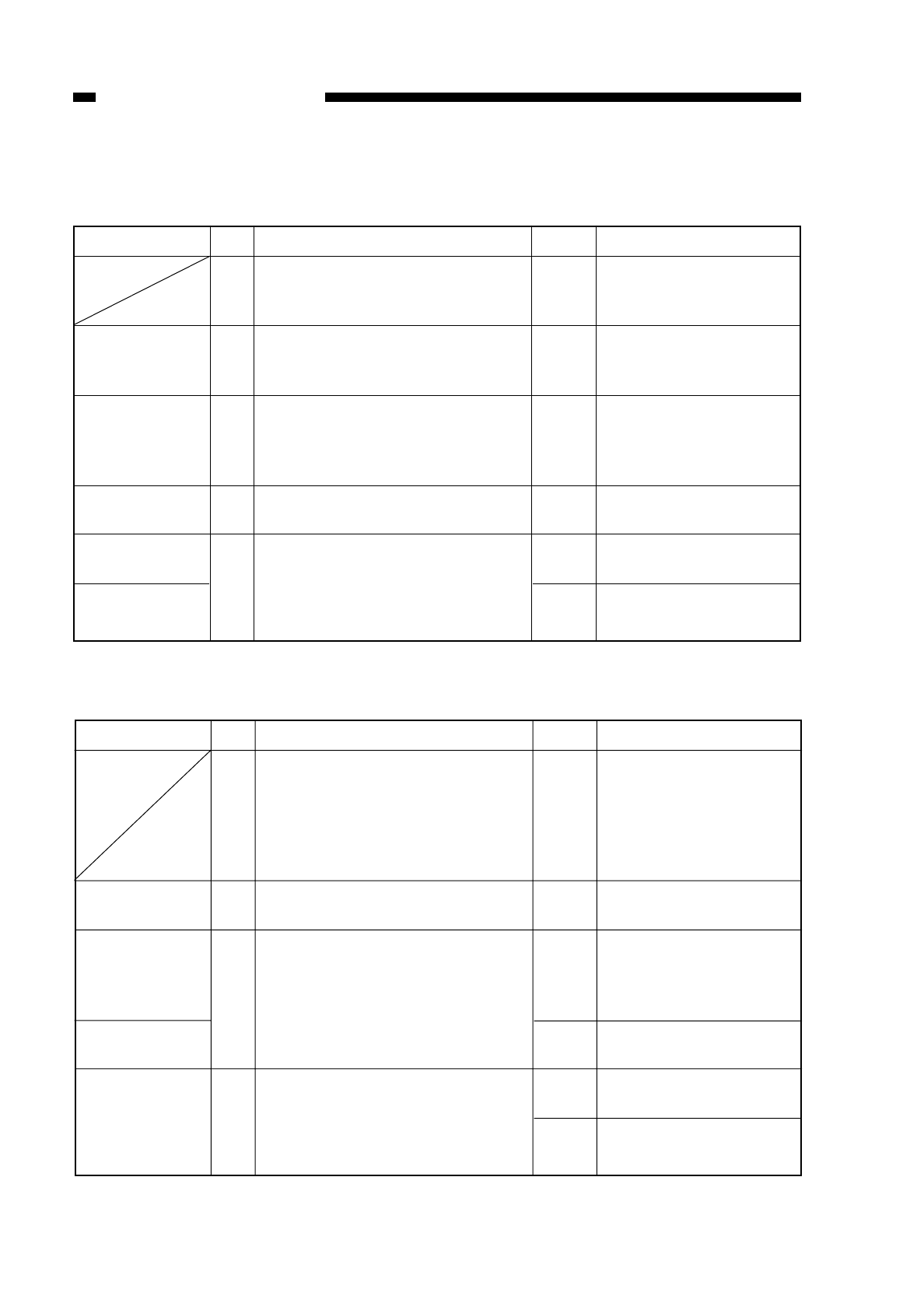
7. The copy is foggy (vertical).
8. The copy has black lines (vertical; thick fuzzy lines).
9. The copy has black lines (vertical, fine).
COPYRIGHT
©
1997 CANON INC. CANON NP6218 REV. 0 MAY 1997 PRINTED IN JAPAN (IMPRIME AU JAPON)
10-54
CHAPTER 10 TROUBLESHOOTING
Checks
Perform the Image Adjustment
Basic Procedure. Is the problem
corrected?
Execute ‘No. 402’ in service mode
(primary charging roller cleaning).
Is the problem corrected?
Clean the scanning lamp, reflect-
ing plate, side reflecting plate,
lens, mirror, and dust-proofing
glass. Is the problem corrected?
Clean the pre-exposure lamp. Is
the problem corrected?
Is the developing cylinder coated
with a uniform layer of toner?
Cause
Primary
charging roller
Scanner
Pre-exposure
lamp
Developing
assembly
Fixing
assembly
Step
1
2
3
4
5
Results
YES
YES
YES
YES
NO
YES
Action
End.
End.
End.
End.
Replace the developing
assembly.
Check and clean the
fixing assembly.
Checks
Make a copy, and turn off the
power switch while the paper is in
the feeding assembly. Are black
lines noted on the copy before it
moves through the fixing
assembly?
Is the transfer guide soiled (in par-
ticular, the upper transfer guide) ?
Are scratches or black lines noted
around the photosensitive drum?
Try wiping the photosensitive
drum with a flannel cloth coated
with toner. Do the lines disap
pear?
Are there scratches or black lines
on the upper fixing film?
Cause
Transfer guide
Photosensitive
drum
Exposure
system
Fixing
assembly
Step
1
2
3
4
Results
NO
YES
YES
NO
YES
NO
Action
Go to step 3.
End.
Replace the drum
cartridge. If scratches
are found, investigate
the cause.
Check the exposure
system.
Replace the upper fixing
unit.
Check the inlet of the
fixing assembly for dirt.

10. The copy has white spot (vertical).
11. The copy has white lines (vertical).
COPYRIGHT
©
1997 CANON INC. CANON NP6218 REV. 0 MAY 1997 PRINTED IN JAPAN (IMPRIME AU JAPON)
10-55
CHAPTER 10 TROUBLESHOOTING
Checks
Make a copy with the copyboard
cover lifted, and turn off the power
switch while the paper is moving
through the feeding assembly. Are
white spots or liens noted on the
copy before it moves through the
fixing assembly?
Execute ‘No. 402’ in service mode
(primary charging roller cleaning).
Is the problem corrected?
Execute ‘No. 409’ in service mode
(transfer roller cleaning). Is the
problem corrected?
Is dirt, cracks, or scratches noted
on the transfer charging roller?
Are the position and condition of
the transfer charging roller
pressure spring normal?
Clean the static eliminator. Is the
problem corrected?
Is the developing cylinder coated
with a uniform layer of toner?
Try fresh copy paper. Is the
problem corrected?
Are there scratches around the
photosensitive drum?
Cause
Fixing
assembly
Primary
charging roller
Transfer
charging roller
Static
eliminator
Developing
assembly
Copy paper
Photosensitive
drum
Light from
outside
Step
1
2
3
4
5
6
7
8
9
Results
NO
YES
YES
YES
NO
YES
NO
YES
YES
NO
Action
1. Clean the inlet guide
(upper, lower) of the
fixing assembly.
2. Check the upper
fixing unit.
End.
End.
Replace the transfer
charging roller.
Correct or replace the
spring.
End.
Take out the developing
assembly, and shake it
several times. If the
problem is not corrected,
replace the developing
assembly.
The copy paper may be
moist; advise the user
on the correct method of
storing paper.
Replace the drum
cartridge. (Be sure to
investigate the cause of
the scratches.)
Check if the photosensi-
tive drum is exposed to
light from outside.

12. The copy has white spots (horizontal).
COPYRIGHT
©
1997 CANON INC. CANON NP6218 REV. 0 MAY 1997 PRINTED IN JAPAN (IMPRIME AU JAPON)
10-56
CHAPTER 10 TROUBLESHOOTING
Checks
Take out the developing assembly,
and shake it several times. Is the
problem corrected?
Is the problem noted at intervals
of about 9.4 cm (scratches in the
photosensitive drum)?
Is the problem noted at intervals
of about 5.1 cm?
Execute ‘No. 402’ in service mode
(primary charging roller cleaning).
Is the problem corrected?
Execute ‘No. 403’ (transfer roller
cleaning) in service mode. Is the
problem corrected?
Is the problem noted at intervals
of about 5.1 cm?
Is dirt, cracks, or scratches noted
on the transfer charging roller?
Are the position and condition of
the transfer charging roller
pressure spring normal?
Try fresh copy. Is the problem
corrected?
Is the problem noted at the same
location on all copies?
Cause
Toner level
Photosensitive
drum
Primary
charging roller
Transfer
charging roller
Copy paper
Scanner rail,
scanner cable
Step
1
2
3
4
5
6
7
8
9
10
Results
YES
YES
YES
YES
YES
YES
YES
NO
YES
YES
Action
The toner level may not
be adequate; advise the
user.
1. Clean the drum.
2. If scratches are found
on the drum, replace
the drum cartridge.
Check the primary
charging roller for
scratches and dirt.
End.
End.
Check the transfer
charging roller for dirt
and scratches.
Replace the transfer
charging roller.
Correct or replace the
spring.
The paper may be moist;
advise the user on the
correct method of storing
paper.
1. Check the scanner
rail for foreign matter.
2. Adjust the tension of
the scanner cable.

13. The back of the copy is soiled.
COPYRIGHT
©
1997 CANON INC. CANON NP6218 REV. 0 MAY 1997 PRINTED IN JAPAN (IMPRIME AU JAPON)
10-57
CHAPTER 10 TROUBLESHOOTING
Checks
Turn off the power switch while
paper is moving through the
feeding assembly. Is the back of
the copy soiled?
Execute ‘No. 403’ in service mode
(transfer roller cleaning). Is the
problem corrected?
Make several solid white copies. Is
the problem corrected?
Is the transfer charging roller
soiled excessively?
Is the problem noted norizontally
at intervals of about 4.2 cm?
Is the problem noted vertically at
intervals of about 1.6 cm?
Is the fixing pressure roller or the
fixing film soiled with toner?
Cause
Transfer
charging roller
Durm cartridge
Drum cleaning
assembly
(drum
cartridge)
Fixing
assembly
Step
1
2
3
4
5
6
7
Results
NO
YES
YES
YES
YES
YES
NO
YES
NO
Action
Go to step 7.
End.
End.
Replace the transfer
charging roller.
1. Clean the registration
roller and transfer
guide.
2. Check the drum
cartridge for leakage
of toner.
1. Clean the manual
feed roller.
2. Check the drum
cartridge for leakage
of toner.
1. Clean the cleaning
assembly.
2. Check the drum
cartridge for leakage
of toner.
Clean the fixing pressure
roller and the fixing film.
Clean the delivery roller
and the fixing assembly
paper guide plate.
14. The copy has a fixing fault.
15, 16, 17 The leading edge of the copy is displaced.
COPYRIGHT
©
1997 CANON INC. CANON NP6218 REV. 0 MAY 1997 PRINTED IN JAPAN (IMPRIME AU JAPON)
10-58
CHAPTER 10 TROUBLESHOOTING
Checks
Is the problem noted vertically?
Is the nip of the fixing assembly
within specification? (Use ‘No.
402’ of service mode.)
Cause
Fixing film
Lower fixing
roller pressure
Copy paper
Step
1
2
Results
YES
NO
YES
Action
Check the fixing film for
scratches.
Replace the lower fixing
roller pressure spring.
Try recommended
paper; if the results are
good, advise the user to
use recommended
paper.
Checks
Is the original placed correctly?
Is the copy paper of a type
recommended by Canon?
Has the pick-up roller or the
separation pad of the cassette
which caused the problem
reached its average life?
Does each registration roller rotate
normally?
Adjust the registration (leading
edge margin; ‘No. 305’ in service
mode). Is the problem corrected?
(See p. 10-5.)
Cause
Original
Copy paper
Pick-up roller,
separation pad
Cassette, paper
guide plate
Registration
Step
1
2
3
4
5
Results
NO
NO
YES
NO
NO
YES
Action
Re-place the original.
Try recommended
paper; if the results are
good, advise the user to
use recommended
paper.
Check the rollers, and
replace those worn.
1. Check if paper is
correctly set in the
cassette.
2. Check the paper
guide for foreign
matter.
See “The registration
roller fails to rotate.”
End.

18. The copy has a blurred image.
CHAPTER 10 TROUBLESHOOTING
Checks
Does the cable overlap on the
cable pulley while the scanner is
moving? Is the cable too loose or
too tight?
Is the scanner rail soiled? Is
foreign matter found on the
scanner rail?
Is the gear of the scanner drive
assembly chipped?
Is the problem noted at intervals
of about 9.4 cm?
Is the problem noted at intervals
of about 4.2 cm?
Cause
Scanner drive
cable
Scanner rail
Scanner drive
system
Photosensitive
drum
Developing
gear
Drum drive
assembly
Step
1
2
3
4
5
Results
YES
YES
YES
YES
YES
NO
Action
1. Re-route the cable.
2. If the cable is twisted
or frayed, replace it.
Clean the surface of the
scanner rail.
Replace the gear.
1. Check the drum drive
gear.
2. Check the drum end,
where it comes into
contact with the
developing spacer, for
scratches or
protrusions.
Check the developing
assembly.
Check the drum drive
assembly.
COPYRIGHT
©
1997 CANON INC. CANON NP6218 REV. 0 MAY 1997 PRINTED IN JAPAN (IMPRIME AU JAPON)
10-59

19. The copy is foggy (horizontal).
COPYRIGHT
©
1997 CANON INC. CANON NP6218 REV. 0 MAY 1997 PRINTED IN JAPAN (IMPRIME AU JAPON)
10-60
CHAPTER 10 TROUBLESHOOTING
Checks
Is the problem noted at the same
position on all copies made in
Direct?
Does the scanning lamp flicker
when the scanner is moving
forward?
Check the developing assembly
spacer for toner adhesion or
deformation. Is toner noted on the
portion (photosensitive drum
surface) where the developing
assembly spacer comes into
contact?
Is the development bias applied
normally?
Make reduced copies, and check
them against copies made in
Direct. Is the problem noted at
different positions?
Cause
Scanning lamp
Developing
assembly spacer
Development
bias
Scanner
Feeding
assembly
Step
1
2
3
4
5
Results
YES
YES
YES
NO
YES
NO
Action
Go to step 5.
Check the scanning
lamp.
Clean or, as necessary,
replace the developing
assembly.
Re-insert the developing
assembly; then, check
the wiring.
Check the scanner.
Check the feeding
assembly.

20. The copy has poor sharpness.
COPYRIGHT
©
1997 CANON INC. CANON NP6218 REV. 0 MAY 1997 PRINTED IN JAPAN (IMPRIME AU JAPON)
10-61
CHAPTER 10 TROUBLESHOOTING
Cause
Original
Copyboard
glass
Lens drive
assembly
Transfer
charging roller
Drum cartridge
Developing
assembly
Development
bias
Mirror
Scanner
Checks
Is the original off the glass
surface?
Is copyboard glass stained with
oil? Is the copyboard glass
attached correctly?
Turn off and on the power switch.
Does the lens move smoothly?
Execute ‘No. 403’ in service mode
(transfer roller cleaning). Is the
problem corrected?
Is the transfer charging roller
securely inserted?
Is dirt, cracks, or scratches noted
on the transfer charging roller?
Are the position and condition of
the transfer roller pressure spring
normal?
Is the drum cartridge securely
set? (Check if the spacer for the
developing assembly is in contact
with the photosensitive drum
under pressure.)
Is the development bias generated
normally?
Is the horizontal reproduction ratio
in Direct with on specification?
Step
1
2
3
4
5
6
7
8
9
10
Results
YES
YES
NO
YES
NO
YES
NO
NO
NO
NO
YES
Action
1. Check the copyboard
cover for warping.
2. Advise the user how
to place an original.
• Clean the copyboard
glass.
• Re-attach the
copyboard glass.
Check the lens drive
assembly.
End.
Re-insert the charging
roller.
Replace the transfer
charging roller.
Correct or replace the
spring.
Replace the drum
cartridge or the
developing assembly.
• Replace the composite
power supply PCB.
(Replace the DC con
troller PCB.)
Adjust the position
between No. 1 and No. 2
mirrors.
Clean the scanning
lamp, reflecting plate,
mirrors, lens, and dust-
proofing glass.
21. The copy is blank.
22. The copy is solid black.
COPYRIGHT
©
1997 CANON INC. CANON NP6218 REV. 0 MAY 1997 PRINTED IN JAPAN (IMPRIME AU JAPON)
10-62
CHAPTER 10 TROUBLESHOOTING
Checks
Is the drum cartridge securely
inserted?
Is the drum cartridge rotating
during copying operation?
Is the transfer charging roller
securely inserted?
Is electrical leakage noted on
the transfer charging roller?
Is the reading in ‘No. 105’ of
service mode (primary charg-
ing current) 10 µA or less?
Cause
Drum cartridge
Drum drive
assembly
Transfer charg-
ing assembly
Composite
power supply
PCB
Step
1
2
3
4
5
Results
NO
NO
NO
YES
YES
Action
Insert the drum
cartridge.
1. Check if the
photosensitive drum
rotates smoothly.
2. Check the drum drive
assembly.
Re-insert the transfer
roller.
Check the transfer
charging roller.
Replace the composite
power supply PCB.
Checks
Does the scanning lamp remain
on during copying operation?
Does the pre-exposure lamp turn
on during copying operation?
Is the reading in ‘No. 105’ of
service mode (primary charging
current) 10 µA or less?
Cause
Composite
power supply
PCB
Step
1
2
3
Results
NO
NO
YES
Action
Make checks according
to the descriptions under
“The scanning lamp fails
to turn on.”
Make checks according
to the descriptions under
“The pre-exposure lamp
fails to turn on.”
Replace the composite
power supply PCB.

IV. TROUBLESHOOTING MALFUNCTIONS
A. Troubleshooting Malfunctions
1. E000
COPYRIGHT
©
1997 CANON INC. CANON NP6218 REV. 0 MAY 1997 PRINTED IN JAPAN (IMPRIME AU JAPON)
10-63
CHAPTER 10 TROUBLESHOOTING
Checks
Disconnect the connector (J4) of
the fixing heater, and press the
power switch while holding down
the service mode switch. (This
clears E000; about 2 sec later,
the power switch turns off
automatically. Is the connection of
J47 (4-pin connector near the rear
side plate fixing assembly)
connected properly?
Let the fixing assembly cool
sufficiently, and disconnect J47. Is
the resistance between J47-1 and
-2 on the thermistor side about
1.4 M and resistance between
J47-3 and -4 about 3.7 M ?
Is electrical continuity present
between J4-1 and -2?
Replace the upper fixing unit. Is
the problem corrected?
Replace the fixing heater driver
PCB. Is the problem corrected?
Cause
J47
(relay
connector to
thermistor)
Thermistor
Heater
Thermistor
Fixing heater
driver PCB
DC controller
PCB
Step
1
2
3
4
5
Results
NO
NO
NO
YES
YES
NO
Action
Re-connect it.
Replace the fixing upper
unit.
Replace the fixing upper
unit.
End.
End.
Replace the DC
controller PCB.
2. E001
3. E002, E003
COPYRIGHT
©
1997 CANON INC. CANON NP6218 REV. 0 MAY 1997 PRINTED IN JAPAN (IMPRIME AU JAPON)
10-64
CHAPTER 10 TROUBLESHOOTING
Checks
Disconnect the connector (J4) of
the fixing heater, and press the
power switch while holding down
the service mode switch. (This
clears E001; about 2 sec later,
the power switch turns off
automatically.) Let the fixing
assembly cool sufficiently; then,
disconnect J4. Is the resistance
between J47-1 and -2 about 0
and the resistance between J47-3
and-4 about 0 ?
Replace the fixing heater driver
PCB. Is the problem corrected?
Cause
Thermistor
Fixing heater
driver PCB
DC controller
PCB
Step
1
2
Results
YES
YES
NO
Action
Replace the fixing upper
unit.
End.
Replace the DC
controller PCB.
Checks
Disconnect the connector (J4) of
the fixing heater, and press the
power switch while pressing the
service mode switch. (This clears
the E code; about 2 sec later, the
power switch turns off
automatically.) Turn on the power
switch; is E000 indicated?
Is the wiring between J304 and
J47 on the DC controller PCB
proper?
Replace the DC controller PCB. Is
the problem corrected?
Cause
Wiring
DC controller
PCB
Fixing heater
driver PCB
Step
1
2
3
Results
YES
NO
YES
NO
Action
See the descriptions
under “E000.”
Correct the wiring.
End.
Replace the fixing heater
driver PCB.

4. E004
5. E007
COPYRIGHT
©
1997 CANON INC. CANON NP6218 REV. 0 MAY 1997 PRINTED IN JAPAN (IMPRIME AU JAPON)
10-65
CHAPTER 10 TROUBLESHOOTING
Cause
Fixing film
Fixing film
tension roller
pressure
Fixing film
Fixing film
sensor
Fixing film
sensor (PS9)
Fixing film
motor (M4)
DC controller
PCB
Checks
Replace the fixing heater driver
PCB. Is the problem corrected?
Cause
Fixing heater
driver PCB
DC controller
PCB
Step
1
Results
YES
NO
Action
End.
Replace the DC
controller PCB.
Checks
Is the fixing film cut or torn?
Does the problem occur when the
fixing film or the upper fixing unit
has been replaced?
Have as many as 200,000 copies
been made?
Is the tension spring of the fixing
film detecting lever normal?
Does it move smoothly?
Is the fixing film sensor (PS9)
normal?
Replace the fixing film motor
(M4).
Is the problem corrected?
Step
1
2
3
4
5
6
Results
YES
YES
YES
NO
NO
YES
NO
Action
Replace the fixing upper
unit
Adjust the fixing roller
pressure. (See p. 10-28.)
Replace the upper fixing
unit.
Correct the spring.
Check the wiring
between connectors
J304 and PS9 on the DC
controller PCB; if
normal, replace PS9.
End.
Replace the DC
controller PCB.
6. E010
7. E030
COPYRIGHT
©
1997 CANON INC. CANON NP6218 REV. 0 MAY 1997 PRINTED IN JAPAN (IMPRIME AU JAPON)
10-66
CHAPTER 10 TROUBLESHOOTING
Cause
Main motor unit
(M1; refers to
main motor and
main motor
driver PCB as
single entity)
DC controller
PCB
Drive belt
DC power
supply
Main motor unit
DC controller
PCB
Checks
Does the main motor rotate until
E010 is turned on?
Set the meter to the 12VDC
range. Does the voltage between
J303-3 (+; MMD) and J303-2 (-; 0
V) on the DC controller PCB
change from about 0 V to about
2.6 V or from about 5 V to about
2.6 V when the Copy Start key is
pressed or when WMUPR starts?
Is the drive belt routed properly?
Is the voltage between the
following connectors of the motor
driver PCB normal?
J501-1 (+; 34 V) and J501-2 (-; 0
V)
Replace the main motor unit. Is
the problem corrected?
Step
1
2
3
4
5
Results
NO
NO
YES
NO
NO
YES
NO
Action
Go to step 3.
Replace the main motor
unit (M1).
Check the contact of the
connector (J502) on the
motor driver PCB and
the wiring from J502 to
the connector (J303) on
the DC controller PCB; if
normal, replace the main
motor unit or the DC
controller PCB.
Re-route the belt.
Check the wiring
between the connector
(J206) on the composite
power supply PCB and
the connector J501) on
the motor driver PCB; if
normal, see “DC power
supply is absent.”
End.
Replace the DC
controller PCB.
Checks
Is the total copy counter operating
normally?
Cause
DC controller
PCB
Step
1
Results
NO
YES
Action
See “The copy counter
fails to operate.”
Replace the DC
controller PCB.
8. E064
9. E202 (keys on control panel invalidated)
COPYRIGHT
©
1997 CANON INC. CANON NP6218 REV. 0 MAY 1997 PRINTED IN JAPAN (IMPRIME AU JAPON)
10-67
CHAPTER 10 TROUBLESHOOTING
Cause
Wire
Composite
power supply
PCB
Transfer charg-
ing assembly,
Transfer
charging roller
Primary
charging roller
High-voltage
cable
Checks
Turn off and on the power switch,
and set ‘1’ as the copy count. Is
E064 indicated after copying
operation?
Set ‘1’ as the copy count, and
press the Copy Start key once
again. Is E064 indicated after
copying operation?
Is a fault noted in the transfer
charging assembly/transfer roller
or contacts?
Detach the drum cartridge, and
check the primary charging roller.
Is a fault noted in the primary
charging roller or the contacts?
Detach the rear cover, and check
the high-voltage cable. Is a
scratch or crack found in the high-
voltage cable?
Step
1
2
3
4
5
Results
YES
YES
YES
YES
YES
Action
Check the harness
between the DC
controller PCB and the
composite power supply
PCB.
Go through steps 3
through 6; then, replace
the composite power
supply PCB.
Replace the transfer
corona assembly/transfer
roller.
Replace the drum
cartridge.
Replace the high-voltage
terminal.
Checks
Is the scanner at home position
when E202 is indicated?
Is the scanner home position
sensor (PS1) normal? (See
descriptions on how to check
photointerrupters.)
Cause
Scanner home
position sensor
(PS1)
DC controller
PCB check
Step
1
Results
NO
NO
YES
Action
See “The scanner fails to
move forward/
in reverse.”
Check the wiring
between the DC
controller PCB and PS1;
if normal, replace PS1.
Replace the DC
controller PCB.
10. E210
11. E220
12. E240
COPYRIGHT
©
1997 CANON INC. CANON NP6218 REV. 0 MAY 1997 PRINTED IN JAPAN (IMPRIME AU JAPON)
10-68
CHAPTER 10 TROUBLESHOOTING
Checks
Turn on the power switch. Does
the lens move?
Is the lens home position sensor
(PS2) normal? (See the
instructions on how to check
photointerrupters.)
Replace the DC controller PCB. Is
the problem corrected?
Cause
Lens home
position sensor
(PS2)
DC controller
PCB
Step
1
2
3
Results
NO
NO
YES
Action
See “The lens fails to
move.”
Check the wiring
between the connector
(J307) on the DC
controller PCB and the
lens home position
sensor (PS2); if normal,
replace PS2.
End.
Checks
Does the scanning lamp turn on?
Replace the DC controller PCB. Is
the problem corrected?
Cause
DC
controller
Composite
power supply
PCB
Step
1
2
Results
NO
YES
NO
Action
See “The scanning lamp
fails to turn on.”
Replace the DC
controller PCB.
Check the wiring
between the DC
controller PCB and the
composite power supply
PCB; if normal, replace
the composite power
supply PCB.
Checks
Turn on and off the power switch.
Cause
DC controller
PCB
Step
1
Results
YES
NO
Action
End.
Replace the DC
controller PCB.
13. E261
14. E710, E711, E712, E717
15. E803
COPYRIGHT
©
1997 CANON INC. CANON NP6218 REV. 0 MAY 1997 PRINTED IN JAPAN (IMPRIME AU JAPON)
10-69
CHAPTER 10 TROUBLESHOOTING
Checks
Turn off and on the power supply.
Is the problem corrected?
Replace the composite power
supply PCB. Is the problem
corrected?
Cause
Power supply
frequency
Composite
power supply
PCB
DC controller
PCB
Step
1
2
Results
YES
YES
NO
Action
End.
• If the problem occurs
frequently, advise the
user to obtain a
frequency stabilizer.
End.
Replace the DC
controller PCB.
Checks
Turn off and on the power switch.
Cause
DC controller
PCB
Step
1
Results
YES
NO
Action
End.
Replace the DC
controller PCB.
Checks
Turn off and on the power switch.
Is the problem corrected?
Replace the DC controller PCB. Is
the problem corrected?
Cause
Malfunction
DC controller
PCB
Composite
power supply
PCB
Step
1
2
Results
YES
YES
NO
Action
End.
End.
Replace the composite
power supply PCB.

16. AC power supply is absent.
COPYRIGHT
©
1997 CANON INC. CANON NP6218 REV. 0 MAY 1997 PRINTED IN JAPAN (IMPRIME AU JAPON)
10-70
CHAPTER 10 TROUBLESHOOTING
Checks
Does an E code turn on when the
power switch is turned on, and the
power switch turn off within about
2 sec?
Is the power plug connected
securely?
Are the front door and the delivery
cover closed securely?
Is the specified voltage present at
the power outlet?
Is the specified voltage present
between J1-1 and J1-2? (J1 is the
2-pin connector on the power cord
mount.)
Is the circuit breaker on the
noise filter PCB off? (Use a
meter.)
Is the specified voltage present
between J13-1 and J13-2? (J13 is
the relay connector located
between the noise filter PCB and
the door switch assembly.)
Detach the door switch (DS1),
and connect the probes of the
meter to F1 and F3 or F2 and F5
of the door switch (fastons). Is the
resistance about 0 Ωwhen the
actuator is pressed and ∞ Ω when
released?
Is the wiring between the door
switch and the composite power
supply PCB normal?
Cause
E code (E000,
E001, E002,
E003 E004)
Power plug
Covers
Main power
supply
Noise filter PCB
(circuit breaker)
Noise filter PCB
Door switch
(DS1)
AC harness
Step
1
2
3
4
5
6
7
8
9
Results
YES
NO
NO
NO
YES
YES
NO
NO
NO
Action
Disconnect the
connector (J4) of the
fixing heater, and turn on
the power switch while
holing down the service
mode switch to clear the
E code; then, check the
error in ‘No. 108’ of
service mode for a
reference to the
appropriate description.
Re-connect the power
plug.
Close the door or the
cover.
Advise the user that the
problem is not of the
copier.
Go to step 7.
Remove the cause; turn
on the circuit breaker.
Replace the noise filter
PCB.
Replace the door switch
(DS1).
Correct the wiring.
17. DC power supply is absent.
COPYRIGHT
©
1997 CANON INC. CANON NP6218 REV. 0 MAY 1997 PRINTED IN JAPAN (IMPRIME AU JAPON)
10-71
CHAPTER 10 TROUBLESHOOTING
Checks
Is electrical continuity present
between J211-1 on the composite
power supply PCB and J309-1 on
the DC controller PCB?
Replace the control panel.
Cause
Connector
(J211, J302,
J309)
Control panel
DC controller
PCB
Step
10
11
Results
NO
YES
NO
Action
Check the connector
(J302) on the DC
controller PCB; if
normal, replace the DC
controller PCB.
End.
Replace the DC
controller PCB.
Checks
Is AC power supply present
between the following terminals?
Composite Power Supply PCB
J2-1 (white) and J2-3 (black)
(J2 is the 3-pin connector on the
power supply cord mount.)
Turn off the power switch, and
disconnect all the following
connectors.
Composite Power Supply PCB
J206, J210
Set the meter to the 20V DC
range, and turn on the power
switch; is the voltage between the
following terminals normal?
Is the fuse of the composite
power supply PCB blown?
Cause
AC power
supply
Wiring, DC load
Fuse
Composite
power supply
PCB
Step
1
2
Results
NO
YES
YES
NO
Action
See “AC power supply is
absent.”
Turn off the power
switch, and connect one
of the disconnected
connectors; then, turn on
the power switch.
Repeat the same on all
connectors to find out
the connector which
activates the protection
circuit; check the wiring
from that connector to
the DC loads.
Replace the fuse.
Replace the composite
power supply.
Connector
J206
J210
Pin No.
1
2
1
2
3
4
5
6
Output
34V
GND
24V
GND
5V
GND
34V
GND
Remarksr
to main
motor
driver PCB
DC con
troller PCB
18. The blank shutter fails to move.
19. The photosensitive drum fails to rotate.
COPYRIGHT
©
1997 CANON INC. CANON NP6218 REV. 0 MAY 1997 PRINTED IN JAPAN (IMPRIME AU JAPON)
10-72
CHAPTER 10 TROUBLESHOOTING
Checks
Does the lens move?
Is the drive of the lens motor
transmitted to the gear of the
blank drive assembly?
Is the blank shutter cable routed
correctly?
Cause
Lens motor
Blank shutter
drive assembly
Blank shutter
cable
Step
1
2
3
Results
NO
NO
NO
Action
See “The lens fails to
move.”
Make corrections so that
the drive is transmitted.
Re-route the cable.
Checks
Is E010 indicated?
Re-insert the drum cartridge. Is
the problem corrected?
Is the belt fro drive routed correctly?
Cause
Drum cartridge
Belt
Main drive
assembly
Step
1
2
3
Results
YES
YES
NO
YES
Action
See “E010.”
End.
Re-route the belt.
Detach the main drive
assembly; correct or
replace pats as
necessary.

20. The pick-up operation fails (from cassette).
21. The pick-up operation from the multifeeder fails.
COPYRIGHT
©
1997 CANON INC. CANON NP6218 REV. 0 MAY 1997 PRINTED IN JAPAN (IMPRIME AU JAPON)
10-73
CHAPTER 10 TROUBLESHOOTING
Checks
Is the paper inside the cassette
under the claws?
Slide out and then in the cassette.
Is the problem corrected?
Does the pick-up roller rotate after
the copy Start key is pressed?
Is the life of the pick-up roller or
the pick-up separation pad at its
limit?
Replace the DC controller PCB. Is
the problem corrected?
Cause
Paper (inside
cassette)
Cassette
Pick-up clutch
(CL2)
Pick-up roller,
pick-up
separation pad
DC controller
PCB
Step
1
2
3
4
5
Results
NO
YES
NO
YES
YES
Action
Advise the user on the
correct method of setting
paper.
End.
• Advise the user on
the correct way to set
the cassette.
Check the wiring from
the connector (J303) on
the DC controller PCB
and the pick-up clutch; if
normal, replace the
clutch.
Replace the pick-up
roller or the pick-up
separation pad.
End.
Checks
Select the multifeeder, and press
the copy Start key. Does the
multifeeder pick-up roller rotate?
Does the paper guide plate spring
up when the Copy Start key is
pressed?
Connect the (+) probe of the
meter to J306-11 on the DC
controller PCB. Does the voltage
change from about 24 V to about
0 V when the Copy Start key is
pressed?
Cause
Multifeeder
pick-up clutch
(CL3)
Paper guide
plate cam
Multifeeder
pick-up
solenoid (SL2)
DC controller
PCB
Step
1
2
3
Results
NO
YES
YES
NO
Action
Check the wiring; if
normal, replace CL3.
Check the position of the
paper guide plate cam
and separation pad; as
necessary, adjust or
replace.
Check the wiring; if
normal, replace SL2.
Replace the DC
controller.

22. The scanner fails to move forward/in reverse.
23. The registration roller fails to rotate.
COPYRIGHT
©
1997 CANON INC. CANON NP6218 REV. 0 MAY 1997 PRINTED IN JAPAN (IMPRIME AU JAPON)
10-74
CHAPTER 10 TROUBLESHOOTING
Checks
Is the cable for the scanner routed
correctly?
Is the scanner rail free of dirt, and
does the scanner move smoothly
when pushed by hand?
Set the meter to the 50V DC
range. Does the index of the
meter point to 34 V when the (+)
probe is connected to JJ210-5
and the (-) probe is connected to
J210-6 on the composite power
supply PCB?
Replace the DC controller PCB. Is
the problem corrected?
Replace the scanner motor. Is the
problem corrected?
Cause
Cable
Scanner path
Composite
power supply
PCB
DC controller
PCB
Scanner motor
Step
1
2
3
4
5
Results
NO
NO
NO
YES
YES
Action
Re-route the cable.
Check the scanner rail
for dirt and foreign
matter; in addition check
for objects that may
come into contact with
the scanner.
See “DC power supply is
absent.”
End.
End.
Checks
Press the Copy Start key. Does
the registration roller rotate for
about 1 sec immediately after the
scanner starts to move forward?
Set the meter to the 30V DC
range. Is the voltage between
J303-5 (+) and J303-6 (-) on the
DC controller PCB change from
about 0 V to about 24 V when the
Copy Start key is pressed?
Cause
Registration
roller
DC controller
PCB
Registration
clutch (CL1)
Step
1
2
Results
YES
NO
YES
Action
Check the drive
assembly of the
registration roller.
Replace the DC
controller PCB.
Check the wiring
between the DC con-
troller PCB and CL1; if
normal, replace the CL1.

24. The scanning lamp fails to turn on.
25. The lens fails to move.
COPYRIGHT
©
1997 CANON INC. CANON NP6218 REV. 0 MAY 1997 PRINTED IN JAPAN (IMPRIME AU JAPON)
10-75
CHAPTER 10 TROUBLESHOOTING
Checks
Turn off the power switch, and
disconnect the power plug. Is the
lamp attached correctly?
Are the ends of the scanning lamp
black?
Replace the DC controller PCB. Is
the problem corrected?
Cause
Scanning lamp
Scanning lamp
DC controller
PCB
Composite
power supply
PCB
Step
1
2
3
Results
NO
YES
YES
NO
Action
Re-attach the lamp.
Replace the scanning
lamp.
Replace the DC
controller PCB.
Check the wiring
between the DC
controller PCB and the
composite power supply
PCB; if normal, replace
the composite power
supply PCB.
Checks
Turn off the power switch, and
detach the rear cover. Do the
change solenoid (SL1) turn on at
power-on? (Check with the naked
eye.)
Are the lens cable, pulley, and rail
normal?
Is 34 V being generated at the
J210-5 on the composite power
supply PCB?
Replace the lens motor. Is the
problem corrected?
Cause
Change
solenoid
(SL1)
Lens cable,
pulley, rail
DC power
supply
DC controller
PCB
Lens motor
(M3)
Step
1
2
3
4
Results
NO
NO
NO
NO
YES
Action
Check the wiring
between the DC
controller and SL1; if
normal, replace SL1.
Check the lens cable,
pulley, and rail; as
necessary, clean or re-
route the cable.
See “DC power supply is
absent.”
Replace the DC
controller PCB.
End.
26. The fixing heater fails to operate.
27. The pre-exposure lamp fails to turn on.
28. The add paper indicator fails to turn off.
COPYRIGHT
©
1997 CANON INC. CANON NP6218 REV. 0 MAY 1997 PRINTED IN JAPAN (IMPRIME AU JAPON)
10-76
CHAPTER 10 TROUBLESHOOTING
Checks
Is E000 indicated?
Replace the DC control PCB. Is
the problem corrected?
Cause
DC controller
PCB
Fixing heater
driver
Step
1
2
Results
YES
YES
NO
Action
See the descriptions
under “E000.”
End.
Replace the fixing heater
drive PCB.
Checks
Detach the drum cartridge, and
execute ‘No. 407’ in service mode.
Does the pre-exposure lamp turn
on normally?
Replace the pre-exposure lamp.
Does it turn on normally?
Cause
DC controller
PCB
Pre-exposure
lamp
DC controller
PCB
Step
1
2
Results
NO
YES
NO
Action
Replace the pre-
exposure lamp.
End.
Check the wiring
between the pre-
exposure lamp and the
DC controller PCB; if
normal, replace the DC
controller PCB.
Checks
Is the cassette set correctly?
Is the following sensor normal
(p. 10-39~10-41)?
PS4: cassette paper sensor
PS2cu: cassette 2 paper sensor
(accessory)
PS4cu: cassette 3 paper sensor
(accessory)
Cause
Cassette
Paper sensor
DC controller
PCB
Step
1
2
Results
NO
NO
YES
Action
Set the cassette
correctly.
Check the lever and
wiring; if normal, replace
the sensor.
Replace the DC
controller PCB.

29 The jam message fails to turn off.
COPYRIGHT
©
1997 CANON INC. CANON NP6218 REV. 0 MAY 1997 PRINTED IN JAPAN (IMPRIME AU JAPON)
10-77
CHAPTER 10 TROUBLESHOOTING
Checks
Identify which sensor has
detected the jam in ‘No. 107’ of
service mode (jam history). Is
paper found near the sensor?
Is the sensor identified in step 1
normal? (See p. 10-36.)
Cause
Paper
Sensor
DC controller
PCB
Step
1
2
Results
YES
NO
YES
Action
Remove the paper.
Check the lever and the
wiring; if normal, replace
the sensor.
Replace the DC
controller PCB.
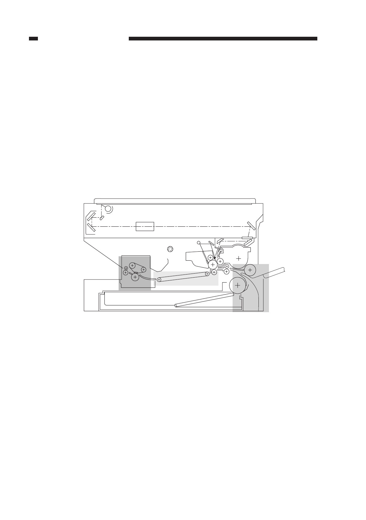
V. TROUBLESHOOTING FEEDING PROBLEMS
A. Jams (copy paper)
Jams tend to occur in the following locations of the copier:
qpick-up assembly
wseparation/feeding assembly
efixing/delivery assembly
The descriptions that follow, therefore, are organized according to each of the above
locations.
When a jam occurs, try to find out the location and the type of the jam in service
mode ([1]; No. 101).
Figure 10-501
COPYRIGHT
©
1997 CANON INC. CANON NP6218 REV. 0 MAY 1997 PRINTED IN JAPAN (IMPRIME AU JAPON)
10-78
CHAPTER 10 TROUBLESHOOTING
e
w
q

1. Pick-Up Assembly
COPYRIGHT
©
1997 CANON INC. CANON NP6218 REV. 0 MAY 1997 PRINTED IN JAPAN (IMPRIME AU JAPON)
10-79
CHAPTER 10 TROUBLESHOOTING
Cause
Cassette
Copy paper
DC controller
PCB, Pick-up
switch
Pick-up roller
Registration
roller drive
assembly
Registration
roller, vertical
path roller
Copy paper
Pick-up roller
Checks
Did the jam occur when the paper
was picked up from the cassette?
Is the cassette set in the copier
correctly?
Try a different cassette. Is the
problem corrected?
Is the copy paper curled or wavy?
Try Canon-recommended paper.
Is the problem corrected?
Does the pick-up roller of the
selected cassette holder rotate
during copying operation?
Is the pick-up roller deformed or
worn?
Try manual copying. Does the
main motor rotate?
Does the registration roller
operate normally?
Is the registration roller or the
vertical path roller deformed or
worn?
Try Canon-recommended paper.
Is the problem corrected?
Step
1
2
3
4
5
6
7
8
9
10
11
Results
NO
NO
YES
YES
YES
NO
YES
NO
NO
YES
YES
NO
Action
Go to step 8.
Set the cassette
correctly.
Check the inside of the
cassette for foreign
matter.
Replace the copy paper;
advise the user for the
correct method of storing
paper.
Advise the user to use
recommended paper.
See “The pick-up
operation fails.”
Replace the pick-up
roller.
See “The pick-up
operation fails.”
See “The registration
roller fails to rotate.”
Replace the deformed or
worn roller.
Advise the user to use
recommended paper.
Check the pick-up roller
for wear or deformation.

2. Separation/Feeding Assembly
3. Fixing/Delivery Assembly
COPYRIGHT
©
1997 CANON INC. CANON NP6218 REV. 0 MAY 1997 PRINTED IN JAPAN (IMPRIME AU JAPON)
10-80
CHAPTER 10 TROUBLESHOOTING
Cause
Transfer charg-
ing assembly
Copy paper
Feed belt
Checks
Is the transfer charging assembly
set correctly?
Are there burrs on the paper guide
of the transfer charging assembly?
Try Canon-recommended paper.
Is the problem corrected?
Are the two feeding belts rotating
properly?
Step
1
2
3
4
Results
NO
YES
YES
NO
YES
Action
Check the transfer
charging assembly.
Remove the burrs.
Advise the user to use
recommended paper.
Check the belt pulley.
Check the feed belt for
deformation or wear.
Cause
Delivery
assembly
separation claw
Lower fixing
roller, fixing
film
Paper guide
Nip
Delivery
lever
Delivery
sensor
(PS1)
Delivery
roller drive
assembly
Leading edge
margin
Checks
Is the separation claw worn or
deformed?
Is the lower fixing roller or the
fixing film deformed or worn?
Is the paper guide soiled with
toner?
Is the lower roller pressure (nip)
within specification?
Does the delivery detection lever
move smoothly?
Does the delivery sensor operate
normally? (See the descriptions
on how to check the
photointerrupters.)
Does the delivery roller move
smoothly?
Step
1
2
3
4
5
6
7
Results
YES
YES
YES
NO
NO
NO
NO
YES
Action
1. Replace the
separation claw.
2. If dirt is found, clean
with solvent.
Replace the roller.
Clean with solvent.
Make adjustments.
Make adjustments so
that the lever moves
smoothly.
Replace the sensor.
Check the delivery roller
drive assembly.
Check if a margin exists
along the leading edge of
the copy.
Fixing assemblyDelivery assembly

B. Feeding Faults
1. Double feeding
2. Wrinkling
COPYRIGHT
©
1997 CANON INC. CANON NP6218 REV. 0 MAY 1997 PRINTED IN JAPAN (IMPRIME AU JAPON)
10-81
CHAPTER 10 TROUBLESHOOTING
Cause
Separation pad
Spring
Checks
Is the separation pad deformed or
worn?
Step
1
Results
YES
NO
Action
Replace the separation
pad.
Push up the separation
pad, and try replacing
the spring.
Cause
Pick-up
assembly
Copy paper
Paper guide
Lower roller
pressure
Top unit,
lower roller
Checks
Turn off the power while copy
paper is moving through the
feeding assembly. At the time, is
wrinkling noted? Or, is the paper
moving askew?
Try fresh paper. Is the problem
corrected?
Is Canon-recommended paper
used?
Is the paper guide soiled with
toner or the like?
Is the lower roller pressure (nip)
within specification?
Step
1
2
3
4
5
Results
YES
YES
NO
YES
NO
YES
Action
Check the pick-up
assembly; check the
registration roller.
The paper may be moist;
advise the user on the
correct method of storing
paper.
Advise the user to use
recommended paper.
Clean with solvent.
Make adjustments.
Try replacing the top unit
or the lower roller.
Fixing assembly
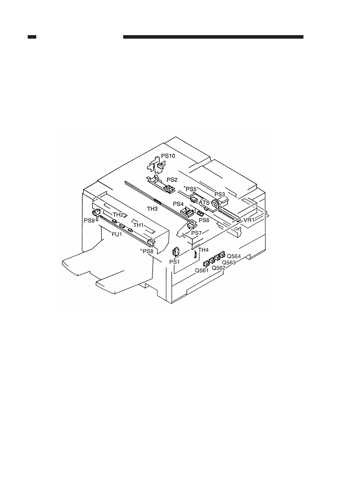
10-82
COPYRIGHT
©
1997 CANON INC. CANON NP6218 REV. 0 MAY 1997 PRINTED IN JAPAN (IMPRIME AU JAPON)
CHAPTER 10 TROUBLESHOOTING
VI ARRANGEMENT/FUNCTIONS OF THE
ELECTRICAL PARTS
A. Sensors
Figure 10-601
10-83
COPYRIGHT
©
1997 CANON INC. CANON NP6218 REV. 0 MAY 1997 PRINTED IN JAPAN (IMPRIME AU JAPON)
CHAPTER 10 TROUBLESHOOTING
Symbol Name
Photointerrupter
Toner sensor
Thermistor
Volume
Thermal fuse
Ref.
PS1
PS2
PS3
PS4
PS5
PS6
PS7
PS8
PS9
PS10
Q561
Q562
Q563
Q564
ATS
TH1
TH2
TH3
TH4
VR1
FU1
Description
detects scanner home position
detects lens home position
detects blank shutter home position
detects presence/absence of paper in cassette
detects presence/absence of paper in multifeeder
detects paper in front of registration roller
detects paper in separation assembly
detects paper in delivery assembly
detects belt
detects right door (open/closed)
cassette size detection 1
cassette size detection 2
cassette size detection 3
cassette size detection 4
detects toner inside developing assembly
fixing heater temperature detection 1
fixing heater temperature detection 2
fluorescent lamp temperature detection
ambient temperature detection
multifeeder paper width detection
fixing heater overheating detection
Table 10-601
PS
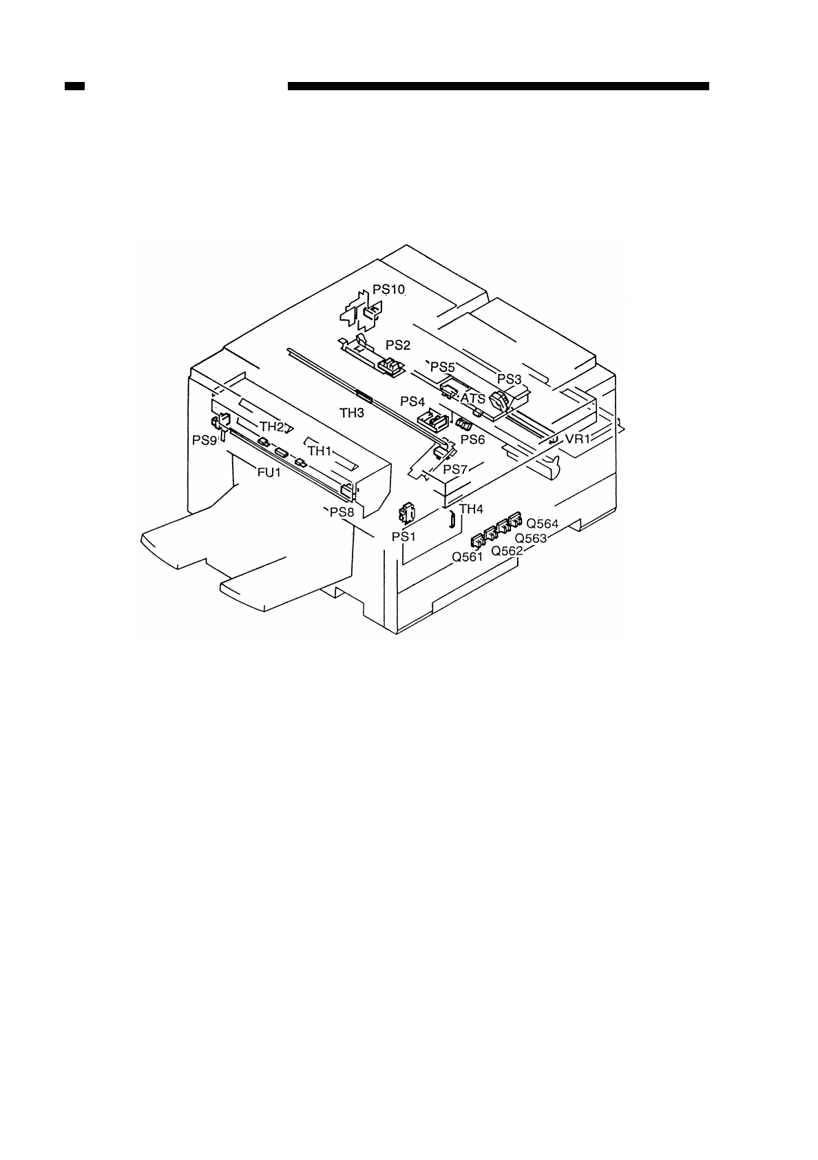
B. Clutches, Solenoids, and Switches
Figure 10-602
10-84
COPYRIGHT
©
1997 CANON INC. CANON NP6218 REV. 0 MAY 1997 PRINTED IN JAPAN (IMPRIME AU JAPON)
CHAPTER 10 TROUBLESHOOTING
10-85
COPYRIGHT
©
1997 CANON INC. CANON NP6218 REV. 0 MAY 1997 PRINTED IN JAPAN (IMPRIME AU JAPON)
CHAPTER 10 TROUBLESHOOTING
Table 10-602
Symbol Name
Clutch
Solenoid
Push switch
Switch
Varistor
Counter
Ref.
CL1
CL2
CL3
SL1
SL2
SL3
SL4
SL5
DS1
SW1
SW2
ZD1
ZD2
CNT1
CNT2
Description
registration clutch
pick-up clutch
multifeeder pick-up clutch
change solenoid
multifeeder holding plate solenoid
blank shutter
primary charging roller cleaning solenoid
transfer changing roller releasing solenoid
door switch
anti-condensation switch
fluorescent lamp heater switch
transfer guide varistor
attraction plate varistor
total copy counter
option counter
CL
SL
CNT
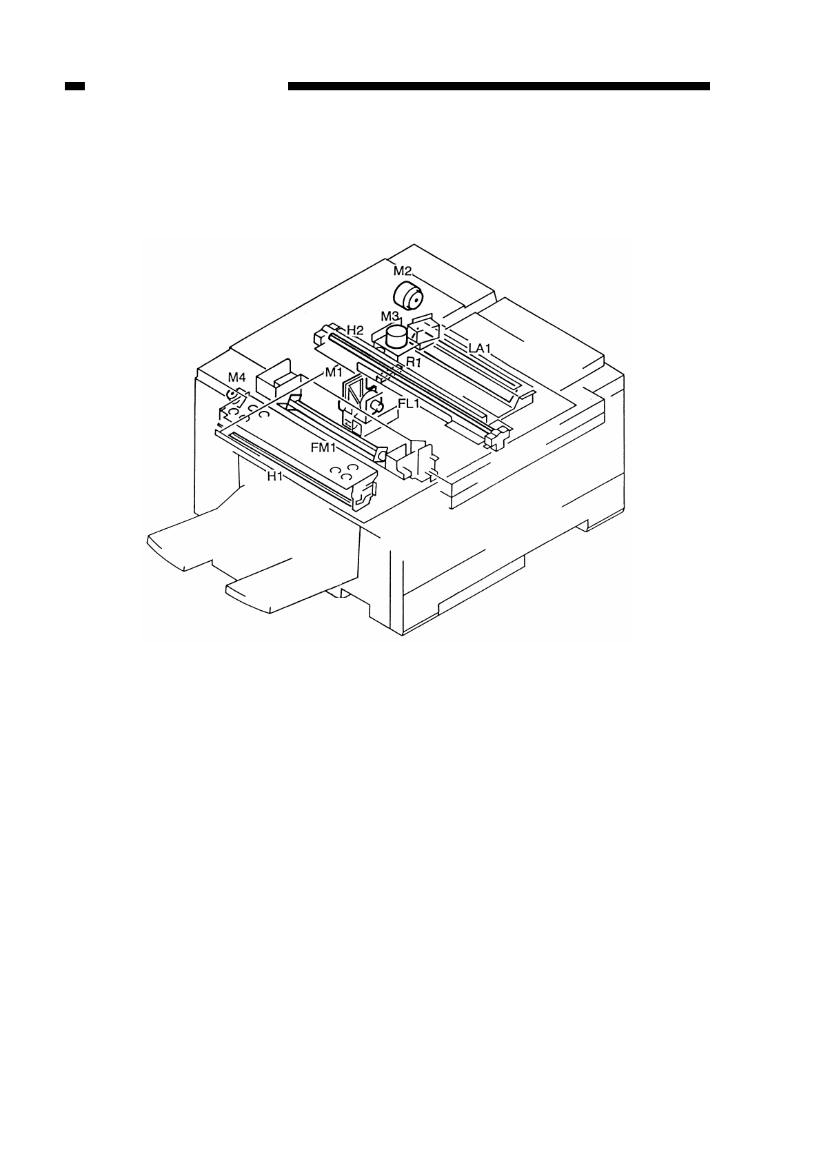
10-86
COPYRIGHT
©
1997 CANON INC. CANON NP6218 REV. 0 MAY 1997 PRINTED IN JAPAN (IMPRIME AU JAPON)
CHAPTER 10 TROUBLESHOOTING
C. Motors, Heaters, and Lamps
Figure 10-603
10-87
COPYRIGHT
©
1997 CANON INC. CANON NP6218 REV. 0 MAY 1997 PRINTED IN JAPAN (IMPRIME AU JAPON)
CHAPTER 10 TROUBLESHOOTING
Table 10-603
Symbol Name
Motor
Fan motor
Heater
Fluorescent
lamp
Lamp
Ref.
M1
M2
M3
M4
FM1
H1
H2
R1
FL1
LA1
Description
main motor
scanning motor
lens motor
fixing belt motor
heat exhaust fan
fixing heater
fluorescent lamp heater
lens heater
scanning lamp
pre-exposure lamp
M
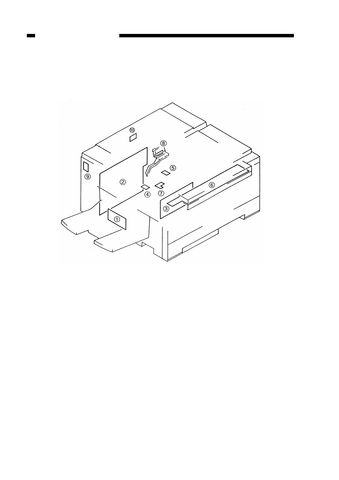
10-88
COPYRIGHT
©
1997 CANON INC. CANON NP6218 REV. 0 MAY 1997 PRINTED IN JAPAN (IMPRIME AU JAPON)
CHAPTER 10 TROUBLESHOOTING
D. PCBs
Figure 10-604

Table 10-604
10-89
COPYRIGHT
©
1997 CANON INC. CANON NP6218 REV. 0 MAY 1997 PRINTED IN JAPAN (IMPRIME AU JAPON)
CHAPTER 10 TROUBLESHOOTING
Ref.
1
2
3
4
5
6
7
8
9
10
Name
Noise filter
Composite power supply
DC controller
AE sensor
Intensity sensor
Control panel
High-voltage connector
Development bias connector
Heater driver
Heater on detection
Function
noise prevention
DC power supply, high-voltage generation
sequence control
original density detection
fluorescent lamp intensity detection
control panel keys, LEDs
charging, transfer, static eliminating power relay
development power relay
fixing heater drive
fixing heater drive detection
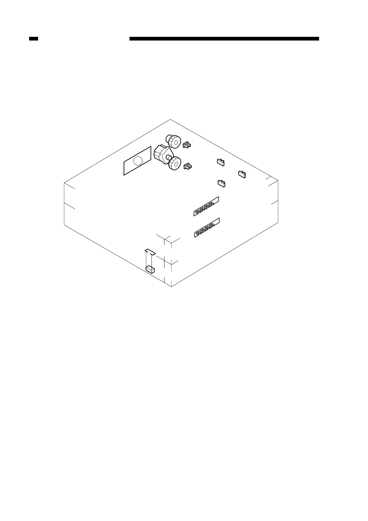
10-90
COPYRIGHT
©
1997 CANON INC. CANON NP6218 REV. 0 MAY 1997 PRINTED IN JAPAN (IMPRIME AU JAPON)
CHAPTER 10 TROUBLESHOOTING
E. Cassette Feeding Module – A2
Figure 10-605
PS1cu
PS3cu PS2cu
M1cu
CL2cu
CL1cu
1
PS4cu
Q564-2
Q563-2
Q562-2
Q561-2
PS5cu
Q564-3
Q563-3
Q562-3
Q561-3
Hcu
10-91
COPYRIGHT
©
1997 CANON INC. CANON NP6218 REV. 0 MAY 1997 PRINTED IN JAPAN (IMPRIME AU JAPON)
CHAPTER 10 TROUBLESHOOTING
Table 10-605
Symbol Name
Photointerrupter
Motor
Clutch
Heater
Cassette driver
Ref.
PS1cu
PS2cu
PS3cu
PS4cu
PS5cu
Q561-2
Q562-2
Q563-2
Q564-2
Q561-3
Q562-3
Q563-3
Q564-3
M1cu
CL1cu
CL2cu
Hcu
Description
mcassette 2 vertical path detection
cassette 2 paper detection
cassette 3 vertical path detection
cassette 3 paper detection
cassette right door open/closed detection
cassette 2 paper size detection 1
cassette 2 paper size detection 2
cassette 2 paper size detection 3
cassette 2 paper size detection 4
cassette 3 paper size detection 1
cassette 3 paper size detection 2
cassette 3 paper size detection 3
cassette 3 paper size detection 4
cassette unit motor
cassette 2 pick-up clutch
cassette 3 pick-up clutch
cassette heater (accessory)
relay PCB
CL
M
PS
q
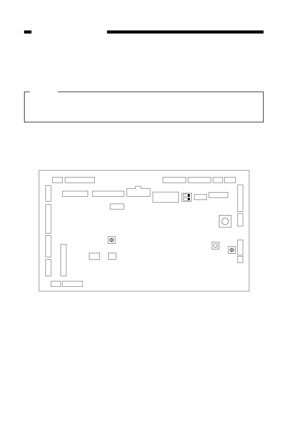
F. Variable Resistors (VR) and Check Pins by PCB
Of all the VRs and check pins found in the copier, those that are needed in the field
are discussed.
Caution:
Do not touch the VRs and check pins that are not discussed herein; they are for
factory adjustment only and require special tools and instruments and must be
adjusted with high precision.
1. DC controller PCB
Figure 10-606
10-92
COPYRIGHT
©
1997 CANON INC. CANON NP6218 REV. 0 MAY 1997 PRINTED IN JAPAN (IMPRIME AU JAPON)
CHAPTER 10 TROUBLESHOOTING
3 J311 1 2 J309 20 1 J310 15
11 J303 1
15 J306 6
7 J307 6 10 J308 1 12 J304 1 1 J305 6
1 J314 121 J315 7J316
12
J317 1
11
J322
J312
83
15 J302 1
5 J318 1
1
J356
21
J324
4
B10 J319 B1
A1 A10
1J301 6
11 J313 1
1
J320
3
SW303 5
1
2
J351
1
J353
SW302
17
1
J321
4
VR302 VR301
VR391
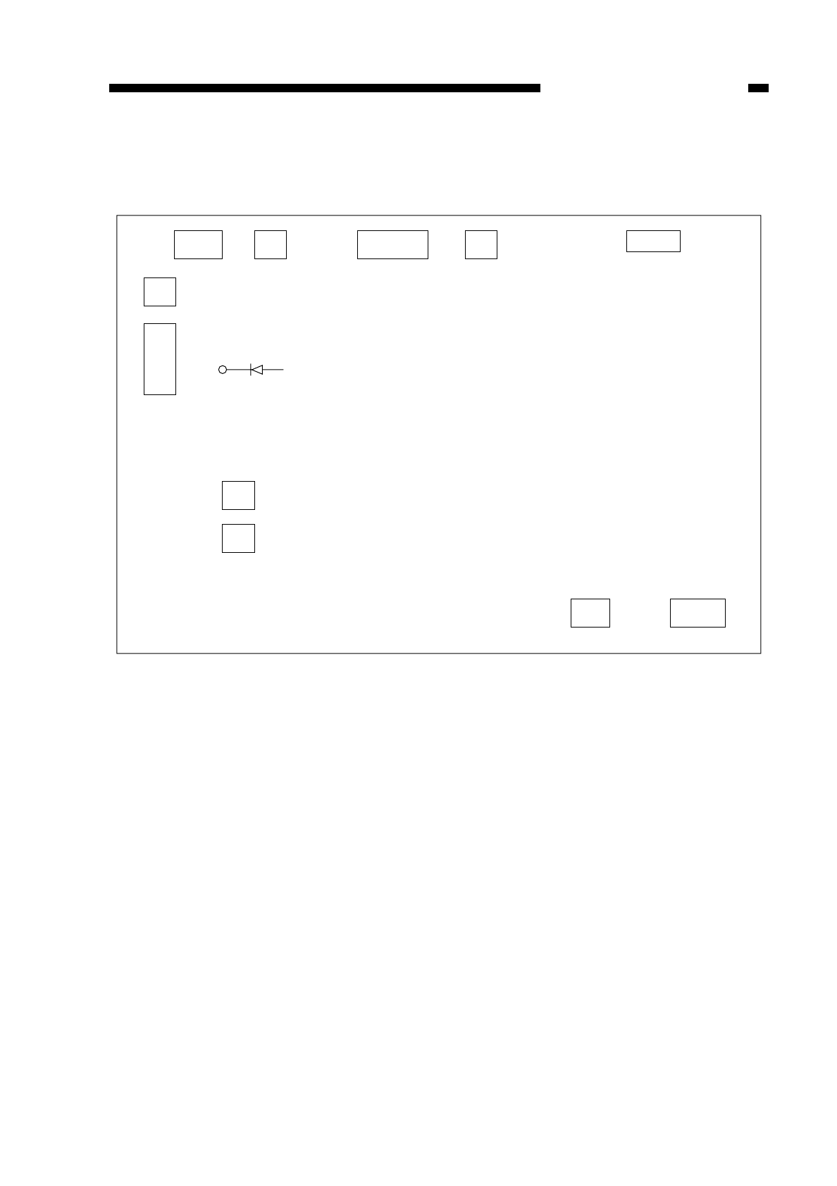
2. Composite power supply PCB
Figure 10-607
10-93
COPYRIGHT
©
1997 CANON INC. CANON NP6218 REV. 0 MAY 1997 PRINTED IN JAPAN (IMPRIME AU JAPON)
CHAPTER 10 TROUBLESHOOTING
J212
13
J209
J211
1
2
J908
1
3
J202
21
J204
31
J906
1
2
LED501
1
15
J213
12
J210
16
J206
12
J205
15
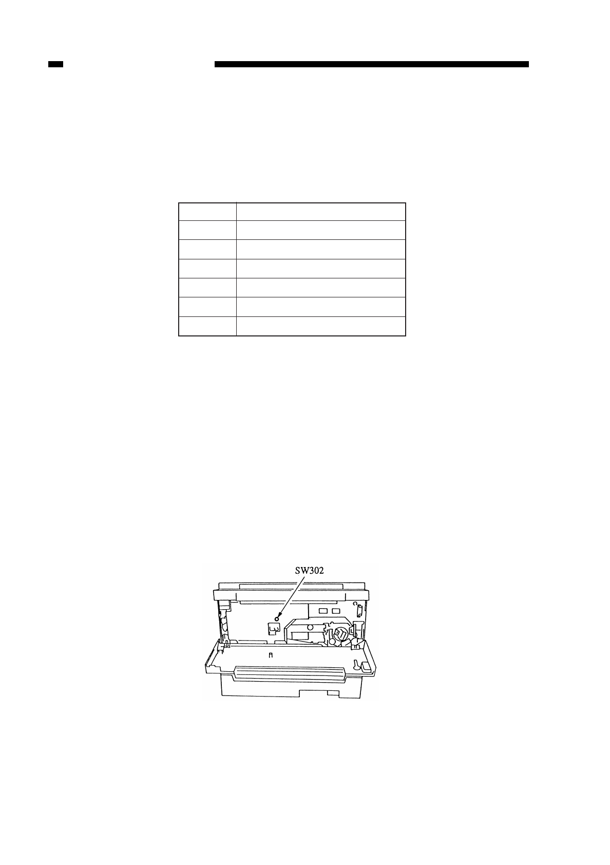
CHAPTER 10 TROUBLESHOOTING
10-94
COPYRIGHT
©
1997 CANON INC. CANON NP6218 REV. 0 MAY 1997 PRINTED IN JAPAN (IMPRIME AU JAPON)
Item
[1]
[2]
[3]
[4]
[5]
[6]
Description
control display mode
I/O display mode
adjustment mode
operation/inspection mode
specification mode
counter mode
VII. SERVICE MODE
A. Outline
The copier’s service mode may be classified into the following six:
Table 10-701
B. Using Service Mode
1. Activating Service Mode
1) Open the front door, and insert the door switch actuator.
• If you want to make checks for I/O display mode or the like while making copies,
set the copy mode.
2) Press the service mode switch (SW302) on the DC controller with hex key.
• The copy count indicator indicates [1].
• While service mode is activated, the copy density indicator LED indicates the
position of the fixing belt.
• A press on the reset key de-activates service mode.
Figure 10-701

CHAPTER 10 TROUBLESHOOTING
10-95
COPYRIGHT
©
1997 CANON INC. CANON NP6218 REV. 0 MAY 1997 PRINTED IN JAPAN (IMPRIME AU JAPON)
2. Selecting a Service Mode
1) While the copy count indicator is indicating [1], press a key from [1] through [6] to
select the appropriate mode.
2) Press the AE key.
• The copier activates the selected mode, and the copy count indicator indicates
‘301’ or the like; ‘301’ represents the first mode of those represented by [3].
3. Selecting Items
1) While the 100th digit on the copy count indicator is flashing (‘301’ or the like), press
the keypad to select the mode to execute.
• The copy count indicator indicates the selected number; only the 100th digit is
flashing.
• A press on the Clear key returns to selecting a mode ([3] or the like).
2) Press the Start key.
• The copier activates the specified mode.
4. Using Adjustment Mode [3] and Specification Mode [5]
1) Press the keypad, and change the setting.
• The value is flashed.
• If the value is a negative value, ‘%’ turns on. To enter a negative value, press the
% key, and then enter the number using the keypad.
2) Press the AE key.
• The copier stores the value, and flashes it.
• A press on the Start key starts copying operation.
3) To change the settings continuously, repeat steps 1) and 2).
4) A press on the Clear key returns to selecting items.
5. Using Operation/Inspection Mode [4]
1) A press on the Start key executes the selected service mode.
2) A press on the Stop key stops the operation and then returns to selecting items.
• If the mode is of a type that stops automatically, the operation stops and returns
to selecting items automatically.
6. Clearing Stored Error Code
If E000, E001, E002, E003, E004, or E007 is indicated, remove the cause of the
error, and clear the back-up information.
1) Open the front door, and insert the door switch actuator.
2) While holding down the service mode switch (SW302) on the DC controller with a hex
key, press the power switch.
3) In about 2 sec, the power goes off; press the power switch once again.
Note:
The copier turns itself off automatically if it detects E000, E001, E002, E003, or
E004, not responding to a press on the power switch. To check the error in service
mode, perform the above after disconnecting the connector of the heater.

CHAPTER 10 TROUBLESHOOTING
10-96
COPYRIGHT
©
1997 CANON INC. CANON NP6218 REV. 0 MAY 1997 PRINTED IN JAPAN (IMPRIME AU JAPON)
No.
301
302
303
304
305
306
307
308
309
310
311
312
313
314
315
316
317
318
319
320
321
322
323
324
325
326
AE_LIGHT
AE_SHIFT
AE_SLOPE
HEATER
REGIST
LE_BLANK
REGIST_R
LE_BLANK_R
TE_BLANK
TE_BLANK_MF
B_HOME
B_HOME_RE
PRIMARY
IP_OFST
PW_OFST
IP_ADJ
PH_ADJ
ATVC_STD
MF_LOOP
C1_LOOP
C2_LOOP
C3_LOOP
C1_CL_OFF
C2_CL_OFF
C3_CL_OFF
LIGHT
TYP
7. Recording on the Service Mode Label
Figure 10-702 shows the label attached behind the front door. At the factory, each
machine is adjusted, and the settings used at the time are recorded on the label.
You must record new settings if you changed them in the field. If you replaced the DC
controller, be sure to store the settings recorded on the label in service mode.
In addition, if you have replaced drun unit or the composite power supply, enter the
settings recorded on the service label attached to the new drum unit or composite
power supply and, at the same time, copy the setting on the service label (Figure 10-
702)
Figure 10-702

CHAPTER 10 TROUBLESHOOTING
C. Control Display Mode [1]
• To select an item, press the appropriate key on the keypad and then the Start key.
• To clear an item, press the Clear key.
• A press on the Start key while a service mode is indicated executes the respective
operation.
Table 10-702
10-97
COPYRIGHT
©
1997 CANON INC. CANON NP6218 REV. 0 MAY 1997 PRINTED IN JAPAN (IMPRIME AU JAPON)
No.
101
102
103
104
105
106
107
108
109
110
111
112
113
114
116
137
138
139
155
Description
Jam location
Fixing belt sensor ON time
Power supply voltage
Primary charging voltage
Primary charging current
Intensity
Jam history
Error history (E code)
Temperature detected by fixing main
thermistor (TH1)
Temperature detected by fixing sub
thermistor (TH2)
Temperature detected by ambient
thermistor (TH301; DC controller)
AE sensor output
ROM version number
ROM release number
Intensity at time of scanning
Factory mode
Factory mode
Factory mode
Factory mode
Remarks
The display indicates the location of the jam
on the copy count indicator; see below.
unit: ms
The actual ON time is the value that is
obtained by multiplying the indicated value
by 2.56; the copy density indicator indicates
the position of the belt.
unit: V
unit: V
The actual primary charging voltage is the
value obtained by turning the displayed value
into negative and subtracting 1000 from it.
unit: µA
unit: lux
The actual intensity (lux) is the value obtained
by dividing the displayed value by 100.
See below.
The display indicates a history of the most
recent three errors; a press on [1], [2], or [3] on
the keypad indicates the most recent, second
recent, and third recent errors respectively.
unit: °C
unit: °C
unit: °C
Normal if the value changes for each
original in AE mode.
Indicates the parts number of the ROM.
Indicates the version of the program.
Normal: between 68 and 72
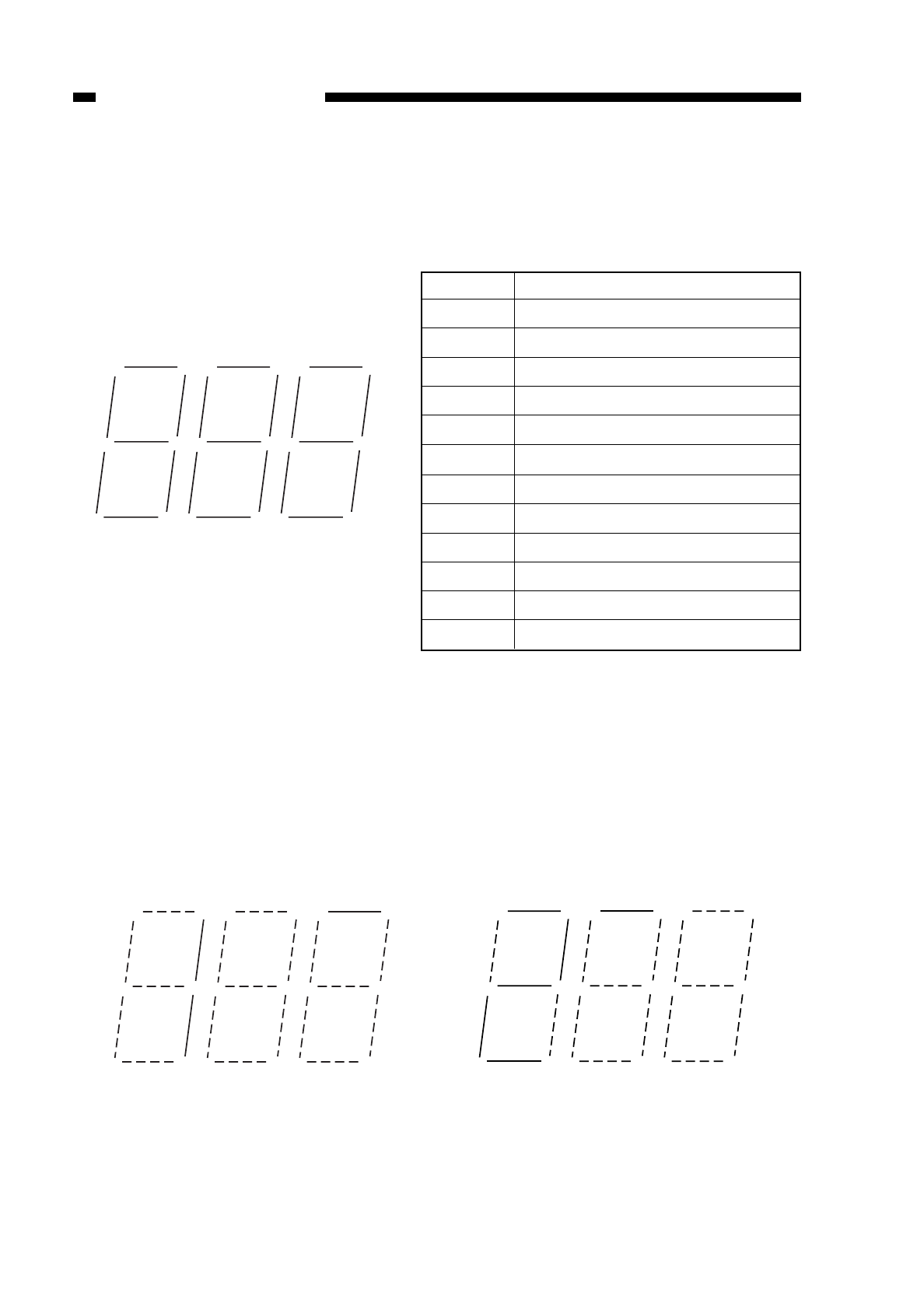
CHAPTER 10 TROUBLESHOOTING
10-98
COPYRIGHT
©
1997 CANON INC. CANON NP6218 REV. 0 MAY 1997 PRINTED IN JAPAN (IMPRIME AU JAPON)
LED (ON)
1-a
1-b
1-c
1-d
1-e
1-f
1-g
2-a
2-b
2-c
2-d
2-e
Jam
pre-registration delay jam
pre-registration stationary jam
separation delay jam
separation stationary jam
delivery delay jam
delivery stationary jam
sorter jam
door open
cassette 2 pick-up delay jam
cassette 2 pick-up stationary jam
cassette 3 pick-up delay jam
cassette 3 pick-up stationary jam
2-a 1-a
2-f 2-b
2-g
2-e 2-c
2-d
1-f
1-g
1-b
1-e
1-d
1-c
No. 101 Jam Location Indicator
In this mode, the copy count indicator turn on to indicate the type of jam. If both delay
and stationary are indicated for the same sensor, i.e., at time of power-on or standby, the
copier has detected copy paper when it was not making copies.
No. 104 Jam History
The 100th digit of the copy count indicator indicates how recent the jam is; to indicate
the jam that occurred second most recently, press [2] on the keypad. As in ‘No. 101’ (jam
location), the 10th digit indicates the type of jam.
Example: The most recent jam is a pre- The second most recent jam is a door
registration delay jam. open jam.
Table 10-703

CHAPTER 10 TROUBLESHOOTING
D. I/O Mode [2]
• Press [2] on the keypad and the AE key to activate I/O display mode.
• To clear an item, press the Clear key.
• A press on the Start key while a service mode is indicated executes the respective
operation.
Table 10-12
10-99
COPYRIGHT
©
1997 CANON INC. CANON NP6218 REV. 0 MAY 1997 PRINTED IN JAPAN (IMPRIME AU JAPON)
No.
201
202
203
204
205
206
207
208
209
210
211
212
213
Description
Port C digit 4
Port C digit 5
Port C digit 6
Port C digit 7
Port H
Fixing main thermistor (TH1) voltage
Fixing sub thermistor (TH2) voltage
AE sensor voltage
Ambient temperature thermistor
(TH301) voltage
Multifeeder paper width sensor
voltage
Intensity sensor voltage
Copy density correction knob/switch
voltage
Toner level sensor
Remarks
When the mode is activated, the copy count
indicator turns on to indicate the I/O of the
input port; see below.
When the mode is activated, the copy count
indicator turns on to indicate the I/O of the
input port; see below.
When this mode is activated, the copy
count indicator turns on to indicate the I/O
of the input port; see below.
When this mode is activated, the copy
count indicator turns on to indicate the I/O
of the input port; see below.
When this mode is activated, the copy
count indicator turns on to indicate the I/O
of the input port; see below.
Indicates the measurement of voltage using
0 through 255.
Indicates the measurement of voltage using
0 through 255.
Indicates the measurement of voltage using
0 through 255.
Indicates the measurement of voltage using
0 through 255.
Indicates the measurement of voltage using
0 through 255.
Indicates the measurement of voltage using
0 through 255.
Indicates the measurement of voltage using
0 through 255.
Indicates the measurement of voltage using
0 through 255.
CHAPTER 10 TROUBLESHOOTING
LED (copy count indicator; from 201 to 205)
No. 201/202/203/204 Port C Digital Display
10-100
COPYRIGHT
©
1997 CANON INC. CANON NP6218 REV. 0 MAY 1997 PRINTED IN JAPAN (IMPRIME AU JAPON)
2-a 1-a
2-f 2-b
2-g
2-e 2-c
2-d
1-f
1-g
1-b
1-e
1-d
1-c
No.
201
202
203
Description
Cassette 2 connect
Cassette 2 connect
Options counter open circuit
Jumper connector 3
Cassette size 1 (cassette 2)
Cassette size 2 (cassette 2)
Cassette size 3 (cassette 2)
Cassette size 4 (cassette 2)
Not used
Main motor lock
Control Card IV connect
Total counter connect
Option counter connect
Cassette size 1 (cassette 3)
Cassette size 2 (cassette 3)
Cassette size 3 (cassette 3)
Cassette size 4 (cassette 3)
Not used
Service mode switch
Jumper connector 1
Jumper connector 2
Total counter open circuit
Cassette size 1 (cassette 1)
Cassette size 2 (cassette 1)
Cassette size 3 (cassette 1)
Cassette size 4 (cassette 1)
Cassette 3 vertical path
sensor (PS3cu)
Remarks
ON: connected
ON: connected
ON: open
ON: connected
ON: light-blocking plate present
ON: light-blocking plate present
ON: light-blocking plate present
ON: light-blocking plate present
ON: locked
ON: connected
ON: connected
ON: connected
ON: light-blocking plate present
ON: light-blocking plate present
ON: light-blocking plate present
ON: light-blocking plate present
ON: pushed
ON: connected
ON: connected
ON: open
ON: light-blocking plate present
ON: light-blocking plate present
ON: light-blocking plate present
ON: light-blocking plate present
ON: light-blocking plate present
LED
1-a
1-b
1-c
1-d
1-e
1-f
1-g
2-a
2-b
1-a
1-b
1-c
1-d
1-e
1-f
1-g
2-a
2-b
1-a
1-b
1-c
1-d
1-e
1-f
1-g
2-a
2-b

CHAPTER 10 TROUBLESHOOTING
Table 10-13
No. 205 Port H Display
Table 10-14
10-101
COPYRIGHT
©
1997 CANON INC. CANON NP6218 REV. 0 MAY 1997 PRINTED IN JAPAN (IMPRIME AU JAPON)
No.
204
Description
Right door open/closed
sensor (PS10)
Separation sensor (PS7)
Cassette paper sensor
(PS4)
Multifeeder paper sensor
(PS5)
Cassette 2 paper sensor
(PS2cu)
Cassette 3 paper sensor
(PS4cu)
Delivery sensor (PS8)
Cassette right door
open/closed sensor (PS5cu)
Cassette 2 vertical path
sensor (PS1cu)
Remarks
ON: light-blocking plate present (paper
present)
ON: light-blocking plate present (right door
closed)
ON: light-blocking plate present (paper
absent)
ON: light-blocking plate present (paper
absent)
ON: light-blocking plate present (paper
absent)
ON: light-blocking plate present (paper
absent)
ON: light-blocking plate present (paper
present)
ON: light-blocking plate present (right door
closed)
ON: light-blocking plate present (paper
present)
LED
1-a
1-b
1-c
1-d
1-e
1-f
1-g
2-a
2-b
Connector
J314-2
J353-6
J307-2
J315-2
J304-12
J324-2
J302-12
J302-14
Description
Registration sensor
PCB check
Lens home position sensor
(PS2)
Blank shutter home position
sensor (PS3)
Fixing film sensor (PS9)
Heater on detection
(triac short circuit)
Composite power supply ACK
AC pulse
Remarks
ON: paper present
For factory only
ON: at HP
ON: at HP
ON film detected
ON: heater ON detected
ON: acknowledged
ON: H, OFF: L
LED
1-a
1-b
1-c
1-d
1-e
1-f
1-g
2-a
2-b
Signal
RPD
PCBCH*
LHP
BSHP
FFD
HTON*
CP-ACK
AC-MNTR

CHAPTER 10 TROUBLESHOOTING
E. Adjustment Mode [3]
• To activate adjustment mode, press [3] on the keypad and then the AE key.
• To select an item, press the appropriate key on the keypad and then the Start key.
• To change the setting, press the appropriate keys on the keypad and then the AE key.
• To cancel an item, press the Clear key.
• A press on the Start key executes the respective operation.
• If the value is a negative value, ‘%’ is turned on; to enter a negative value, press
the % key and the value on the keypad.
Table 10-15-1
Note: A press on the Start key when in No. 305, 306, 307, or 308 makes copies in
the mode that has been effective before the activation of the mode; when
executing No. 307 or 308, it is recommended that page separation mode be
selected before activating service mode.
10-102
COPYRIGHT
©
1997 CANON INC. CANON NP6218 REV. 0 MAY 1997 PRINTED IN JAPAN (IMPRIME AU JAPON)
No.
301
302
303
304
305
306
307
308
309
310
Description
Automatic lamp intensity
adjustment for AE scans
Copy density (development bias)
reference point adjustment for
AE mode
Copy density (development bias)
slope adjustment for AE mode
Fixing heater resistance storage
Leading edge margin adjustment
(registration roller ON timing)
Leading edge non-image width
adjustment (timing at which
blank open/close shutter for
blank exposure is closed)
Leading edge registration adjust-
ment for right face in page separa-
tion (registration roller ON timing)
Leading edge margin adjustment for
right face in page separation (timing
at which blank shutter is closed)
Trailing edge non-image width
adjustment (timing at which
open/close shutter for blank
exposure is opened)
Leading edge non-image width
for multifeeder (timing at which
the open/close shutter for blank
exposure is opened)
Remarks
See p. 10-11.
See p. 10-13.
default: 0
See p. 10-13.
default: 0
See p. 10-31.
A higher value delays the copy
paper in relation to the image,
reducing the margin.
default: 32 unit: 0.27 mm
A higher setting increases the
leading edge non-image width.
default: 32 unit: 0.27 mm
A higher setting delays the copy
paper in relation to the image.
default: 32 unit: 0.27 mm
A higher setting increases the
leading edge margin.
default: 32 unit: 0.27 mm
A higher setting reduces the trailing
edge margin.
default: 32 unit: 0.27 mm
A higher setting reduces the trailing
edge margin.
default: 32
unit: 0.27 mm
Settings
-26 ~ +26
-26 ~ +26
0 ~ 63
0 ~ 63
0 ~ 63
0 ~ 63
0 ~ 63
0 ~ 63

CHAPTER 10 TROUBLESHOOTING
10-103
COPYRIGHT
©
1997 CANON INC. CANON NP6218 REV. 0 MAY 1997 PRINTED IN JAPAN (IMPRIME AU JAPON)
No.
311
312
313
314
315
316
317
318
319
Description
Left/right margin adjustment
(Direct; home position for slide
shutter for blank exposure)
Left/right margin adjustment
(Reduce; travel distance of slide
shutter for blank exposure)
Primary output voltage correction
(corrects output voltage
determined by APVC)
APVC measured current shift
(corrects the results of APVC)
Voltage correction for
measurement in APVC (corrects
voltage for measurement applied
at time of APVC)
Measurement current correction
for APVC (corrects current
measured at time of APVC)
Fluorescent lamp pre-heating
current adjustment
Transfer output voltage
adjustment (corrects transfer
voltage determined by ATVC)
Arch adjustment when
multifeeder is used (pick-up roller
OFF timing)
Remarks
A higher setting increases the
margin on both left and right.
default: 8
unit: 0.27 mm
A higher setting increases the
margin on both left and right.
default: 0
unit: 0.27 mm
Enter the setting recorded on the label
after replacing the drum cartridge.
Enter the setting recorded on the label
after replacing the drum cartridge.
default: 0
unit: 16 V
Enter the value recorded on the label
on the composite power supply when
replacing the composite power supply.
default: 0
Enter the value recorded on the
label on the composite power
supply when replacing the
composite power supply.
default: 0
Enter the value recorded on the
label on the composite power
supply when replacing the
composite power supply.
Convert the value recorded on the
label on the composite power
supply as follows and change the
value recorded on the service label;
then, enter the value when replacing
the composite power supply.
Label Input Label Input
1
→06→+1
2→-1 7 →+2
3→-2 8 →+3
4→-3 9 →+4
5→-4
A higher setting increases the arch.
default: 25
unit: 0.27 mm
Settings
0 ~ 15
-10 ~ +10
-16 ~ +16
-40 ~ +40
-16 ~ +16
-10 ~ +10
-9 ~ +9
-4 ~ +4
0 ~ 63

CHAPTER 10 TROUBLESHOOTING
Table 10-15-2
10-104
COPYRIGHT
©
1997 CANON INC. CANON NP6218 REV. 0 MAY 1997 PRINTED IN JAPAN (IMPRIME AU JAPON)
No.
320
321
322
323
324
325
326
Description
Arch adjustment when cassette
2 is used (pick-up roller OFF
timing)
Arch adjustment when cassette
2 is used (pick-up roller OFF
timing)
Arch adjustment when cassette
2 is used (pick-up roller OFF
timing)
Pick-up clutch (CL2) off timing
adjustment
Cassette 2 pick-up clutch
(CL1cu) off timing adjustment
Cassette 3 pick-up clutch
(CL2cu) off timing adjustment
Scanning lamp intensity
adjustment
Remarks
A higher setting increases the arch.
default: 25
unit: 0.27 mm
A higher setting increases the arch.
default: 25
unit: 0.27 mm
A higher setting increases the arch.
default: 25
unit: 0.27 mm
For factory only
default: 32
For factory only
default: 20
For factory only
default: 20
For factory only
default: 75
Settings
0 ~ 63
0 ~ 63
0 ~ 63
0 ~ 63
0 ~ 63
0 ~ 63
0 ~ 76

CHAPTER 10 TROUBLESHOOTING
F. Operation/Inspection Mode [4]
• To activate operation/inspection mode, press [4] on the keypad and then the AE key.
• To select an item, press the appropriate key on the keypad and then the Start key.
• To execute the mode, press the Start key.
• To stop the operation, press the Stop key; the copier returns to selecting an item.
• If the mode is of a type that stops automatically, the copier automatically returns
to selecting an item.
10-105
COPYRIGHT
©
1997 CANON INC. CANON NP6218 REV. 0 MAY 1997 PRINTED IN JAPAN (IMPRIME AU JAPON)
No.
401
402
403
404
405
406
407
408
409
Description
Developing assembly idle rotation
Primary roller cleaning
Transfer roller cleaning
Fixing tension roller
Fixing film initial rotation mode
Nip check
Fixing film displacement correction
Scanning lamp ON check
Control panel indicators ON
Remarks
Use it after supplying toner at time of installation.
Use it to adjust the fixing film drive roller
pressure for the upper fixing unit. (See p. 10-
28.) Fix the fixing tension roller and cause the
fixing film to rotate idly. The ON period of the
fixing film sensor is indicated by the copy
count indicator, and the film position is
indicated by the copy density indicator.
Another press on the Start key checks the
position of the fixing film automatically.
Execute the mode when you have replaced
the fixing film or the upper fixing unit to return
the fixing film to its appropriate position. (See
p. 10-28.) The film stops as soon as it
reaches the appropriate position automatically.
The position of the film in travel is indicated by
the copy density indicator.
Use tit to check the nip or when adjusting the
lower fixing roller. (See p. 10-30.)
The fixing film stops when it reaches the
appropriate position or when 30 sec has
passed. The position of the film in travel is
indicated by the copy density indicator, and
the fixing film ON period is indicated by the
copy count indicator. The position is normal if
the copy density indicator indicates ‘5’ when
the film stops; otherwise, check the fixing film
and the tension roller. If the fixing film
becomes displaced and E007 is indicated, try
this mode. (This will prove to be highly useful
if displacement occurs because of a minor
accident.)
A press on the Start key keeps the lamp on
after about 1.5 sec.

CHAPTER 10 TROUBLESHOOTING
Table 10-16
10-106
COPYRIGHT
©
1997 CANON INC. CANON NP6218 REV. 0 MAY 1997 PRINTED IN JAPAN (IMPRIME AU JAPON)
No.
410
411
412
450
Description
Scanner forward stop
Pre-exposure lamp on
Drum unit installation mode
Back-up RAM clear
Remarks
Execute it when installing or replacing the
drum unit; a press on the Start key will
automatically activate APVC measurement
mode; the mode ends in about 23 sec.
See p. 10-35

CHAPTER 10 TROUBLESHOOTING
10-107
COPYRIGHT
©
1997 CANON INC. CANON NP6218 REV. 0 MAY 1997 PRINTED IN JAPAN (IMPRIME AU JAPON)
G. Specification Settings Mode [5]
• To activate specification settings mode, press [5] on the keypad and then the AE key.
• To select an item, press the appropriate key on the keypad and then the Start key.
• To change the setting, press the appropriate keys on the keypad and then the AE key.
• To clear an item, press the Clear key.
• A press on the Start key executes the respective operation.
Table 10-17
No.
501
502
503
504
505
506
507
508
Description
Characteristics storage for
multifeeder paper width sensor
Copy density notation switching
(9/17 steps)
Auto power-off cancel
Copy count upper limit
Universal cassette paper size
Separation static eliminator output
voltage switching
Fixing forced wait
Fixing control temperature
switching
Remarks
See p. 10-43.
9 steps: 0
17 steps: 1
default: 0 (9 steps)
• When ‘1’ is entered on the keypad, the
notation will be ‘ON’, activating the auto
power-off function.
• When ‘0’ is entered on the keypad, the
notation will be ‘OFF’, de-activating the auto
power-off function.
default: on.
The auto power-off period is set in user mode;
since the copier’s WAIT time is 0, it is best to
keep the auto power-off mechanism to be
enabled.
settings:0 to 99
default: 0
When set to ‘0’, the upper limit will be 100
copies.
See p. 10-44.
settings:0 to 14
default: 0
002: 2.5 kV
004: 4 kV
default: 0
When activated, the period of initial rotation is
increased; activate it if the fixing on the first copy
is poor because of low temperature conditions.
0: disabled
1: enabled
default: 0
001: 225°C See p. 10-32.
002: 215°C
003: 200°C
default: 002

H. Counter Mode [6]
• To activate the mode, press [6] on the keypad and then the AE key.
• To select an item, press the appropriate key on the keypad and then the Start key.
• To cancel an item, press the Clear key.
• A press on the Start key executes the respective service operation.
• To obtain the actual count, multiply the indication by 100.
Table 10-18
10-108
COPYRIGHT
©
1997 CANON INC. CANON NP6218 REV. 0 MAY 1997 PRINTED IN JAPAN (IMPRIME AU JAPON)
CHAPTER 10 TROUBLESHOOTING
No.
601
602
603
Description
Large copy counter
Small copy counter
Total copy counter/drum counter
Remarks
For North America only; indicates the use of
the drum unit in terms of copies made, and
cleared when the drum unit is replaced.

VIII. SELF DIAGNOSIS
A. Copier
The microprocessor on the copier’s DC controller is provided with a self diagnosis
mechanism that checks the condition of the machine (sensors, in particular). The copier
runs self diagnosis and, when it identifies an error, indicates a code that represents each
specific error. If the copier finds an error associated with E000, E001, E002, E003, and
E004, it automatically shuts itself off (error auto power-off).
Table 10-19-1
10-109
COPYRIGHT
©
1997 CANON INC. CANON NP6218 REV. 0 MAY 1997 PRINTED IN JAPAN (IMPRIME AU JAPON)
CHAPTER 10 TROUBLESHOOTING
Code Cause
• Thermistor (TH1, TH2;
displacement, poor
contact, open circuit)
• Fixing heater (H1; open
circuit, crack)
• Thermal fuse (FU1;
malfunction)
• Triac (faulty)
• DC controller (faulty)
• Thermistor (TH1, TH2;
short circuit)
• Triac (faulty)
• DC controller (faulty)
• Thermistor (TH1, TH2;
displacement, poor
contact, open circuit)
• Fixing heater (H1; open
circuit, crack)
• Thermal fuse (FU1;
malfunction)
• Triac (faulty)
• DC controller (faulty)
Description
• Beginning 1 second after the copy START key
is pressed, the main thermister (TH1) does
not reach 50°C for 200 ms.
• Beginning 2 second after the copy START key
is pressed, the main thermister (TH1) does
not reach 60°C for 200 ms.
• Beginning 4 second after the copy START key
is pressed, the main thermister (TH1) does
not reach 70°C for 200 ms.
• The detection temperature of the thermistor
(TH1) exceeds 250°C during copying operation.
• The detection temperature of the sub
thermistor (TH2) exceeds 260°C during
copying operation.
• The detection temperature of the thermistor
(TH1, TH2) rises 30°C over the specified
temperature during copying operation.
• The detection temperature of the thermistor
(TH1, TH2) rises 30°C over the specified
temperature during copying operation.
• The thermistor detects a rise in temperature of
40°C or more during standby.
• The temperature has increased over 100°C or
more within 1 sec after the thermistor (TH1,
TH2) has detected 100°C.
• Beginning 1 second after the main thermister
(TH1) detection temperature reaches 60°C, the
first thermister does not reach 70°C for 200 ms.
• Beginning 1 second after the main thermister
(TH1) detection temperature reaches 70°C, the
first thermister does not reach 80°C for 200 ms.
• Beginning 1 second after the main thermister
(TH1) detection temperature reaches 80°C, the
first thermister does not reach 90°C for 200 ms.
• Beginning 1 second after the main thermister
(TH1) detection temperature reaches 90°C, the
first thermister does not reach 95°C for 200 ms.
E000
E001
E002

Table 10-19-2
10-110
COPYRIGHT
©
1997 CANON INC. CANON NP6218 REV. 0 MAY 1997 PRINTED IN JAPAN (IMPRIME AU JAPON)
CHAPTER 10 TROUBLESHOOTING
Code Cause
• Thermistor (TH1, TH2;
displacement, poor contact,
open circuit)
• Fixing heater (H1; open circuit,
crack)
• Thermal fuse (FU1;
malfunction)
• Triac (faulty)
• DC controller (faulty)
• Triac (faulty)
• Heater ON detection PCB
(faulty)
• Fixing film (displacement, tear)
• Tension roller (displacement,
malfunction)
• Fixing film motor (M4; faulty)
• Fixing film sensor (PS9; faulty)
• Main motor (M1; faulty)
• DC controller (faulty)
• Counter (open circuit)
• DC controller (faulty)
• Composite power supply
(faulty)
• DC controller (faulty)
• Scanner cable (displacement, tear)
• Scanner home position sensor
(PS1; faulty)
• Scanner motor (M2; faulty)
• DC controller (faulty)
Description
• After the main thermistor (TH1) detection
temperature reaches 95°C, the main ther-
mister detects lower than 95°C for 200 ms.
• After the sub thermistor (TH2) detection
temperature reaches 70°C, the sub ther-
mister detects less than 70°C for 200 ms.
The fixing heater is identified as being on
when the fixing heater drive signal is off
(HTRD=0).
The fixing film sensor output remains ‘1’ or
‘0’ for 1.35 sec or more.
Reference:
The fixing film takes about 1.3 sec to make
a full rotation.
The main motor revolution is not as speci-
fied (MLOCK=0) for 1 sec or more while the
main motor drive signal is on (MMD=1).
Checks are made immediately before the
counter turns on or off and when copying
operation is started.
Normal if drive signal = 0 at time the
counter turns on; Normal if drive signal = 1
at time the counter turns off.
Note: Checks are made only when the
counter is installed.
The high voltage of the composite power
supply is different from the setting.
The scanner does not return to the home
position within 5 sec when it is started.
E002 may be checked in ‘No. 108’ of
service mode.
E003
E004
E030
E007
E010
E064
E202
(keys on
control panel
disabled)

Table 10-19-3
10-111
COPYRIGHT
©
1997 CANON INC. CANON NP6218 REV. 0 MAY 1997 PRINTED IN JAPAN (IMPRIME AU JAPON)
CHAPTER 10 TROUBLESHOOTING
Code Cause
• Lens cable (displacement, tear)
• Lens home position sensor
(PS2; faulty)
• Slide shutter (operation)
• Blank shutter home position
sensor (PS3; faulty)
• Change solenoid (SL1; faulty)
• Lens motor (M3; faulty)
• DC controller (faulty)
• Scanning lamp (faulty)
• Composite power supply
(faulty)
• DC controller (faulty)
• DC controller (faulty)
• Composite power supply
(faulty)
• Power supply frequency
(fluctuation)
• Composite power supply
(faulty)
• DC controller (faulty)
• DC controller (faulty)
• DC controller (faulty)
• DF controller (faulty)
• Connector (poor contact)
• DC controller (faulty)
• The Remote Diagnostic
Device II controller (faulty)
• Communication (with the
Remote Diagnostic Device II)
Description
• The lens home position sensor signal
(LHP) is not generated within a specific
period of time after the power switch has
been turned on.
• The lens home position signal (LHP) is
generated longer than a specific period of
time.
• The blank shutter home position signal
(BSHP) is not generated when the slide
shutter is moving.
• The lamp is identified as being on during
standby.
• The lamp is identified as being off during
copying operation.
A communication error is detected between
the CPU (Q301) on the DC controller and the
CPU (Q512) on the composite power supply.
The intervals of the zero cross signal is
outside the tolerance.
The IPC (Q104) cannot be initialized at
power-on.
An IPC communication error has been
detected twice within 1 sec.
An error in communication with the DF
cannot be cleared.
• A communication with the Remote
Diagnostic Device II has been
successfully but failed in the middle.
• An open circuit is detected on the line with
the Remote Diagnostic Device II.
E210
E220
E717
E240
E261
E711
E712
E710

Clearing an Error Code (back-up data)
When the self diagnosis mechanism has been activated, the copier may be reset by
turning its power off and on. However, this does not work for E000, E001, E002, E003,
or E004; this arrangement is to prevent the user from causally resetting any of the errors,
which could damage the film or the heater in side the fixing assembly.
If E000, E001, E002, E003, or E004 is indicated, remove the cause and clear the
back-up data as follows:
1) Open the front door, and insert the door switch actuator.
2) Press the power switch while holding down the service mode switch (SW302) on the
DC controller with a hex key.
3) The power should go off in about 2 sec; turn on the power.
Caution:
Detection of E000, E001, E002, E003, or E004 automatically turns off the copier. To
check the type of error in service mode, go through the above steps after
disconnecting the fixing heater.
10-112
COPYRIGHT
©
1997 CANON INC. CANON NP6218 REV. 0 MAY 1997 PRINTED IN JAPAN (IMPRIME AU JAPON)
CHAPTER 10 TROUBLESHOOTING

B. Self Diagnosis (ADF)
Table 10-20
Note:
To reset the copier after activation of the self diagnosis mechanism, switch the
copier off and then on.
You can still continue to make copies even when the ADF is out of order; simply
open the ADF, and set the documents on the copyboard glass.
10-113
COPYRIGHT
©
1997 CANON INC. CANON NP6218 REV. 0 MAY 1997 PRINTED IN JAPAN (IMPRIME AU JAPON)
CHAPTER 10 TROUBLESHOOTING
Code Cause
• data communication with
copier (error)
• belt motor (fails to rotate)
• belt motor clock sensor (faulty)
• delivery motor (fails to rotate)
• delivery motor clock sensor
(faulty)
• document detection (faulty)
• registration sensor (faulty)
• document edge sensor (faulty)
Description
The data communication is monitored at all
times; the error is identified if the
communication with the copier is absent for
5 sec or more.
The belt clock pulses within 200 msec are
below the specified number.
The delivery motor clock pulses within
200 msec are below the specified number.
The output of the sensor is 2.3 V or more in
the absence of paper.
E400
E402
E404
E411

10-114
COPYRIGHT
©
1997 CANON INC. CANON NP6218 REV. 0 MAY 1997 PRINTED IN JAPAN (IMPRIME AU JAPON)
CHAPTER 10 TROUBLESHOOTING
C. Self Diagnosis (sorter)
Table 10-21
Note:
Some copiers use ‘E500’ to represent all the above errors.
■Error Condition
qThe copier indicates the “TURN ON POWER” message.
wWhen the power has been turned off and then on, the sorter runs a self check: if the
result is good*, it resets; otherwise, enters down state**.
■Down State
qThe copier indicates ‘E5XX’.
wWhen the sorter has been detached, the copier is available for operations other than
those that must use the sorter.
eIf a mode that uses the sorter is selected, some copiers indicate the “MODE NOT
AVAILABLE” message.
Code Cause
The CPU or the communica-
tions IC on the sorter controller
is not operating normally.
The feeder motor fails to rotate.
The stapler guide bar swing
motor fails to rotate.
The stapler unit swing motor
fails to rotate.
The bin shift motor fails to
rotate.
• Bin motor (faulty)
• Reed cam drive gear (faulty
mounting)
Description
An error is detected in the communication
between the sorter and the copier.
The clock signal from the motor is off for
250 msec or more.
The home position sensor does not turn off
after generation of 2560 pulses of the motor
drive signal.
• The stapler unit swing sensor does not
turn off within 0.5sec after generation of
the motor drive signal.
• The sensor does not turn on again within
1.0sec after the stapler unit swing sensor
has turned off.
• The reed cam home position sensor does
not turn off within 2.0sec after generation
of the motor drive signal.
• The reed cam home position sensor does
not turn on once again within
2.0sec after it has turned off.
The reed cam position sensor does not turn
on within 1.0 sec after it has turned off.
E500
E510
E530
E531
E540
E541

10-115
COPYRIGHT
©
1997 CANON INC. CANON NP6218 REV. 0 MAY 1997 PRINTED IN JAPAN (IMPRIME AU JAPON)
CHAPTER 10 TROUBLESHOOTING
Note:
Even in down state, the sorter will run a self check and rest if the result is good if
you have switched it off and then on without detaching it from the copier.
* Simply turn off the joint sensor (MS3) to detach the sorter from the copier; you
need not disconnect the communication connector.
** When an E code is indicated.

10-116
COPYRIGHT
©
1997 CANON INC. CANON NP6218 REV. 0 MAR. 1997 PRINTED IN JAPAN (IMPRIME AU JAPON)
CHAPTER 10 TROUBLESHOOTING

COPYRIGHT
©
1997 CANON INC. CANON NP6218 REV. 0 MAY 1997 PRINTED IN JAPAN (IMPRIME AU JAPON)
APPENDIX
A. GENERAL TIMING CHART ...............A-1
B. SIGNALS AND ABBREVIATIONS......A-2
C. GENERAL CIRCUIT DIAGRAM.........A-3
D. SPECIAL TOOLS ...............................A-5
E. SOLVENTS/OILS................................A-6

A. GENERAL TIMING CHART
(A4, 2 copies, Direct, from copier cassette)
COPYRIGHT
©
1997 CANON INC. CANON NP6218 REV. 0 MAY 1997 PRINTED IN JAPAN (IMPRIME AU JAPON)
A-1
1
2
3
4
5
6
7
8
9
10
11
12
13
14
15
16
17
18
19
20
21
22
23
Sequence STBY INTR
AER
SCFW SCRV SCFW SCRV
LSTR
STBY
Main motor (M1)
Pre-exposure lamp
Primary charging (APVC)
Primary charging bias
Scanning motor (M2)
Scanning lamp (FL1)
Image exposure
Transfer cleaning bias
Transfer bias
Static eliminator bias
Developing bias (AC)
Developing bias (DC)
Fixing heater (H1)
Heat exhaust fan (FM1)
Environment heater (H3)
Fluorescent lamp heater (H2)
Blanking shutter solenoid
(SL3)
Transfer reference bias
(ATVC)
Registration sensor (PS6)
Separation sensor (PS7)
Delivery sensor (PS8)
Scanner home position
sensor (PS1)
Power switch
ON
0 5 10 15 20 25 30
Copy start key
ON
Pick-up clutch (CL2)
Registration clutch (CL1)

B. SIGNALS AND ABBREVIATIONS
1. Signals and Abbreviations
COPYRIGHT
©
1997 CANON INC. CANON NP6218 REV. 0 MAY 1997 PRINTED IN JAPAN (IMPRIME AU JAPON)
A-2
ACBIAS DEVELOPING AC BIAS VOLTAGE DETECTION signal
AE AE SENSOR OUTPUT signal AE
AEREF AE SENSOR REFERENCE signal AE
ATTH AMBIENT TEMPERATURE THERMISTOR signal
BIASS DEVELOPING DC BIAS VOLTAGE DETECTION signal
BPWM DEVELOPING BIAS DRIVE command
BSHP BLANKING SHUTTER HOME POSITION signal
BSSLD BLANKING SHUTTER SOLENOID DRIVE command
C2PUCLD CASSETTE2 PICK-UP CLUTCH DRIVE command
C2SZ-1 CASSETTE2 SIZE signal
C2SZ-2 CASSETTE2 SIZE signal
C2SZ-3 CASSETTE2 SIZE signal
C2SZ-4 CASSETTE2 SIZE signal
C2PD CASSETTE2 PAPER DETECTION signal
C2VPD CASSETTE2 VERTICAL PATH PAPER DETECTION signal
C3PD CASSETTE3 PAPER DETECTION signal
C3PUCLD CASSETTE3 PICK-UP CLUCTH DRIVE command
C3SZ-1 CASSETTE3 SIZE signal
C3SZ-2 CASSETTE3 SIZE signal
C3SZ-3 CASSETTE3 SIZE signal
C3SZ-4 CASSETTE3 SIZE signal
C3VPD CASSETTE3 VERTICAL PATH PAPER DETECTION signal
CCD CONTROL CARD DRIVE command
CCDT CONTROL CARD DETECTION signal
CDC COPY DENSITY CORRECTION signal
CHSLD CHANGE SOLENOID DRIVE command
CMA CASSETTE UNIT MOTOR PULSE command A
CMA* CASSETTE UNIT MOTOR PULSE command A*
CMB CASSETTE UNIT MOTOR PULSE command B
CMB* CASSETTE UNIT MOTOR PULSE command B
CMD CASSETTE UNIT MOTOR DRIVE command
CPD CASSETTE PAPER DETECTION signal
CRDOP CASSETTE RIGHT DOOR OPEN signal
CS CASSETTE SIZE DETECTION command
CS2 CASSETTE2 SIZE DETECTION command
CS3 CASSETTE3 SIZE DETECTION command
CSZ-1 CASSETTE SIZE signal 1
CSZ-2 CASSETTE SIZE signal 2
CSZ-3 CASSETTE SIZE signal 3
CSZ-4 CASSETTE SIZE signal 4
DPD DELIVERY PAPER DETECTION signal
EHTRL EARTH RL DRIVE command RL2
FFA FUSER FILM MOTOR PULSE command A
FFA* FUSER FILM MOTOR PULSE command A*
FFB FUSER FILM MOTOR PULSE command B
FFB* FUSER FILM MOTOR PULSE command
FFCA FUSER FILM MOTOR VOLTAGE command A
FFCB FUSER FILM MOTOR VOLTAGE command B
FFD FIXING FILM POSITION signal
FLHT OFF FLUORESCENT LAMP HETER OFF command
FL ON FLUORESCENT LAMP ON command
FLPRHT FLUORESCENT LAMP PRE-HEAT command
FLS FLUORESCENT LAMP INTENSITY signal
FLTH FLUORESCENT LAMP THERMISTOR signal
FLTH ON FLUORESCENT LAMP HETER ON command
FMD FUSER FILM MOTOR DRIVE command
HEFD HEAT EXHAUST FAN DRIVE command
HTNG FUSER HEATER NG signal
HTRD HEATER DRIVE command
JCTL DISCHARGE BIAS DRIVE command
JLVCTL DISCHARGE BIAS CHANGE command
LHP LENS HOME POSITION signal
LID LIGHT INTENSITY signal
LNSA LENS MOTOR PULSE command A
LNSA* LENS MOTOR PULSE command A*
LNSB LENS MOTOR PULSE command B
LNSB* LENS MOTOR PULSE command B*
LNSC-A LENS MOTOR DRIVE command A
LNSC-B LENS MOTOR DRIVE command B
MFPD MULTIFEEDER PAPER DETECTION signal
MFPUCLD MULTIFEEDER PICK-UP CLUTCH DRIVE command
MFPWD MULTIFEEDER PAPER WIDTH DETECTION signal
MFSLD MULTIFEEDER SOLENOID DRIVE command
MLOCK MAIN MOTER LOCK signal
MMCLK MAIN MOTOR CLOCK signal
MMD MAIN MOTER DRIVE command
MPWM MAIN PULSE command
PCLSLD PRIMARY CORONA ROLLER CLEANING SOLENOID command
PDCPWM PRIMARY CORONA DETECT PULSE command
PDCS PRIMARY CORONA DETECT command
PEXP PRE-EXPOSURE LAMP LIT command
PUCLD PICK-UP CLUTCH DRIVE command
PWSW POWER SWITCH command
RDOP RIGHT DOOR OPEN signal
RGCLD REGISTRATION CLUTCH DRIVE command
RPD REGISTRATION PAPER DETECTION signal
SC-A SCANNER MOTOR PULSE command A
SC-A* SCANNER MOTOR PULSE command A*
SC-B SCANNER MOTOR PULSE command B
SC-B* SCANNER MOTOR PULSE command B*
SC-COMA SCANNER MOTOR DRIVE command A
SC-COMB SCANNER MOTOR DRIVE command B
SCHP SCANNE HOME POSITION signal
SPD SEPARATION PAPER DETECTION signal
SRSW SERVICE MODE SWITCH signal
TCNTD TOTAL COUNTER DRIVE command
TEP TONER EMPTY signal
TFWON TRNSFER BIAS ON/OFF command
TFWPWM TRNSFER BIAS LOW VOLTAGE signal
TFWS TRNSFER BIAS PULSE command
TH 1 FIXING MAIN THERMISTOR signal
TH 2 FIXING SUB THERMISTOR signal
TREVON TRNSFER REVERSE ON command

C. GENERAL CIRCUIT DIAGRAM
COPYRIGHT
©
1997 CANON INC. CANON NP6218 REV. 0 MAY 1997 PRINTED IN JAPAN (IMPRIME AU JAPON)
A-3
not available

COPYRIGHT
©
1997 CANON INC. CANON NP6218 REV. 0 MAR. 1997 PRINTED IN JAPAN (IMPRIME AU JAPON)
A-4
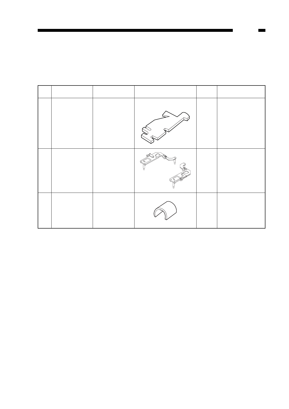
D. SPECIAL TOOLS
See the table for the special tools used to service the machine in addition to the
standard tools set.
COPYRIGHT
©
1997 CANON INC. CANON NP6218 REV. 0 MAY 1997 PRINTED IN JAPAN (IMPRIME AU JAPON)
APPENDIX
A-5
No.
1
2
3
Tool name
Door switch
actuator
Mirror
positioning tool
(comes in
pairs; front,
rear)
Pulley clip
Tool No.
TKN-0093-000
FY9-3009-040
FY9-3010-000
Shape
Point of use
Front door
Rank
A
B
B
Remarks
For adjusting the
distance between
No. 1 and No. 2
mirrors.
For fixing the
scanning cable in
place.
A
A
B
B

E. SOLVENTS/OILS
COPYRIGHT
©
1997 CANON INC. CANON NP6218 REV. 0 MAY 1997 PRINTED IN JAPAN (IMPRIME AU JAPON)
APPENDIX
A-6
No.
1
2
3
4
5
6
Name
Ethl alcohol
(Ethanol)
Isopropyl
alcohol
(Isopropanol)
MEK
Heat-resis-
tant grease
Lubricating
oil (low
viscosity)
Lubricating
oil (low
viscosity)
Lubricating
oil
Use
Cleaning:
copyboard glass,
mirror, etc.
Removing toner
or oil stains
Lubricating the
drive
mechanisms;
e.g., copyboard
driving gear,
fixing drive gear,
fixing ass’y, etc.
Lubrication points:
Scanner rail, etc.
Lubrication point:
oneway clutch in
pick-up control
assembly
Lubrication point:
friction parts
Composition
C2H5OH
(CHZ3)2CHOH
CH3• CO • C2H5
Methylethyl ketone
ISO VG 68 oil
ESSO Febis K68
MOBIL Vactraoil No. 2
SHELL Tonna oil T68
ISO VG 220 oil
ESSO Febis K220
MOBIL Vactraoil No. 4
Silicone oil
Description
• Flammable.
• Use in a well ventilated
area.
• Avoid breathing
concentrated vapor.
• Flammable.
• Use in a well-ventilated
area and avoid breathing
concentrated vapor.
• Avoid contact with eyes or
skin.
• Do not use for cleaning
the drum, plastic molded
parts, or corona wires.
Tool No.: CK-0427 (500g can)
(Equivqlent grease can be
used, but should be able to
withstand 200°C for
extended periods of time.)
Equivalent oil can be used.
Tool No.: CK-0451 (100cc)
Equivalent oil can be used.
Tool No.: CK-0524 (100cc).
Tool No.: CK-0551 (20g)

Prepared by
OFFICE IMAGING PRODUCTS TECHNICAL SUPPORT DEPT. 1
OFFICE IMAGING PRODUCTS TECHNICAL SUPPORT DIV.
CANON INC.
Printed in Japan
REVISION 0 (MAY 1997) [31625]
5-1, Hakusan 7-chome, Toride-shi, Ibaraki 302 Japan

PRINTED IN JAPAN (IMPRIMÉ AU JAPON)
0797S0.7-2
This publication is printed on
70% reprocessed paper.
