Canon Copier Ir2200 Users Manual
IR2800 to the manual 0acf19d2-5942-4843-a150-7ad8ec9c88f9
2015-01-23
: Canon Canon-Copier-Ir2200-Users-Manual-240998 canon-copier-ir2200-users-manual-240998 canon pdf
Open the PDF directly: View PDF ![]() .
.
Page Count: 724 [warning: Documents this large are best viewed by clicking the View PDF Link!]
- Cover
- Introduction
- Cover-System Unit
- Table of Contents
- Chapter 1-General Description
- Chapter 2-Main Controller
- Chapter 3-Installation
- Cover-Reader Unit
- Table of Contents
- Chapter 1-Basic Operation
- Chapter 2-Original Exposure System
- Chapter 3-Image Processing System
- Cover-Printer Unit
- Table of Contents
- Chapter 1-Introduction
- Chapter 2-Sequence of Operations
- Chapter 3-Laser Exposure System
- Chapter 4-Image Formation System
- Chapter 5-Pick-Up/Feeding System
- Chapter 6-Fixing Assembly
- Chapter 7-Externals & Controls
- Chapter 8-Paper Deck-L1
- Chapter 9-Cassette Feeding Unit-W1
- Chapter 10-Inner 2 Way Tray-A1
- Chapter 11-Envelope Feeder Attachment-B1
- Cover-Troubleshooting
- Table of Contents
- Chapter 1-Maintenance & Inspection
- Chapter 2-Image Adjustment Basic Procedure
- Chapter 3-Standards & Adjustments
- Chapter 4-Troubleshooting Image Faults/Malfunctions
- Chapter 5-Service Mode
- Chapter 6-Self Diagnosis
- Chapter 7 Upgrading
- Appendix

FY8-13H8-000
MAR. 2001
iR2200/iR2800/
iR3300
REVISION 0
COPYRIGHT
©
2001 CANON INC. CANON iR2200/iR2800/iR3300 REV.0 MAR. 2001 PRINTED IN U.S.A.
Application
This manual has been issued by Canon Inc. for qualified persons to learn technical
theory, installation, maintenance, and repair of products. This manual covers all
localities where the products are sold. For this reason, there may be information in this
manual that does not apply to your locality.
Corrections
This manual may contain technical inaccuracies or typographical errors due to
improvements or changes in products. When changes occur in applicable products or in
the contents of this manual, Canon will release technical information as the need arises.
In the event of major changes in the contents of this manual over a long or short period,
Canon will issue a new edition of this manual.
The following paragraph does not apply to any countries where such provisions are
inconsistent with local law.
Trademarks
The product names and company names used in this manual are the registered
trademarks of the individual companies.
Copyright
This manual is copyrighted with all rights reserved. Under the copyright laws, this
manual may not be copied, reproduced or translated into another language, in whole or
in part, without the written consent of Canon Inc.
Caution
Use of this manual should be strictly supervised to avoid disclosure of confidential information.
COPYRIGHT © 2001 CANON INC.
Printed in U.S.A.
Imprimé au U.S.A.
COPYRIGHT
©
2001 CANON INC. CANON iR2200/iR2800/iR3300 REV.0 MAR. 2001 PRINTED IN U.S.A.
COPYRIGHT
©
2001 CANON INC. 2000 2000 2000 2000 CANON iR2200/iR2800/iR3300 REV.0 MAR. 2001
INTRODUCTION
i
Indicates an item of a non-specific nature, possibly classified as Note, Caution,
or Warning.
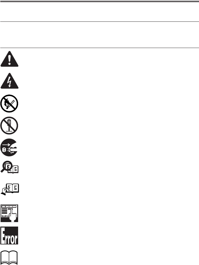
1 Symbols Used
This documentation uses the following symbols to indicate special information:
Symbol Description
Indicates an item requiring care to avoid combustion (fire).
Indicates an item prohibiting disassembly to avoid electric shocks or problems.
Indicates an item requiring disconnection of the power plug from the electric
outlet.
Indicates an item intended to provide notes assisting the understanding of the
topic in question.
Memo
Indicates an item of reference assisting the understanding of the topic in ques-
tion.
REF.
Provides a description of a service mode.
Provides a description of the nature of an error indication.
Refers to the Copier Basics Series for a better understanding of the contents.
Indicates an item requiring care to avoid electric shocks.

COPYRIGHT
©
2001 CANON INC. 2000 2000 2000 2000 CANON iR2200/iR2800/iR3300 REV.0 MAR. 2001
INTRODUCTION
ii
2 Outline of the Manual
This Service Manual contains basic information needed to service the iR2200/iR2800/
iR3300 and its accessories (i.e., side paper deck, shift tray) in the field, conducted for the
purpose of maintaining its product quality and a specific level of performance. A separate
Service Manual is made available for each of its accessories (except for the side paper deck
and shift tray); for details, refer to the appropriate manual.
This Service Manual consists of the following chapters:
1. System Unit
Chapter 1 General Description: features, specifications, names of parts, func-
tions, operation, system configuration, rou-
tine maintenance by the user
Chapter 2 Main Controller: functional construction, outline of electrical
circuitry, principles of operation of the image
processing system, power supply
Chapter 3 Installation: site conditions and installation procedure,
relocation of the machine, installation of ac-
cessories
2. Reader Unit
Chapter 1 Basic Operation: functional construction, outline of electrical
circuitry, basic sequence of operations
Chapter 2 Original Exposure System: principles of operation of the exposure sys-
tem, timing of operation, disassembly/assem-
bly and adjustment
Chapter 3 Image Processing System: principles of operation of the image process-
ing system, timing of operation, disassembly/
assembly and adjustment
3. Printer Unit
Chapter 1 Introduction: safety of the laser, image formation, auxiliary
processes
Chapter 2 Sequence of Operations: basic operations, outline of electrical cir-
cuitry, basic sequence of operations
Chapter 3 Laser Exposure System: principles of operation of the laser exposure
system, timing of operation, disassembly/
assembly and adjustment
Chapter 4 Image Formation System: principles of operation of the image forma-
tion system, timing of operation, disassem-
bly/assembly and adjustment
Chapter 5 Pickup/Feeding System: principles of operation of the pickup/feeding
system, timing of operation, disassembly/
assembly and adjustment

COPYRIGHT
©
2001 CANON INC. 2000 2000 2000 2000 CANON iR2200/iR2800/iR3300 REV.0 MAR. 2001
INTRODUCTION
iii
Chapter 6 Fixing System: principles of operation of the fixing system,
timing of operation, and disassembly/assem-
bly and adjustment
Chapter 7 Externals and Controls: principles of operation of the externals/con-
trols, timing of operation, disassembly/as-
sembly and adjustment
Chapter 8 Paper Deck-L1: principles of operation, timing of operation,
disassembly/assembly and adjustment
Chapter 9 Casstte Feeding Unit-W1: principles of operation, timing of operation,
disassembly/assembly adjustment
Chapter 10 Inner 2Way Tray-A1: principles of operation, timing of operation,
disassembly/assembly adjustment
Chapter 11 Envelope Feeder Attachment-B1:
principles of operation, timing of
operation,disassembly/assembly adjustment
4. Troubleshooting
Chapter 1 Maintenance and Inspection: table of periodically replaced parts, table of
consumables/durables, scheduled servicing
chart
Chapter 2 Image Adjustment Basic Procedure:
basic procedure for image adjustment
Chapter 3 Standards and Adjustments: standards and adjustments
Chapter 4 Troubleshooting Image Faults/Malfunctions:
troubleshooting image faults/malfunctions
Chapter 5 Service Mode: how to use service mode, list of service
modes
Chapter 6 Self Diagnosis: codes, causes of errors
Chapter 7 Upgrading: how to upgrade
Appendix: general timing chart, general circuit diagrams
The descriptions are updated from time to time to reflect product improvements, and ma-
jor changes are communicated in the form of Service Information bulletins.
All service persons are expected to familiarize themselves with the contents of this Ser-
vice Manual and Service Information bulletins and acquire a level of knowledge and skill
required to promptly respond to the needs of the field.

COPYRIGHT
©
2001 CANON INC. 2000 2000 2000 2000 CANON iR2200/iR2800/iR3300 REV.0 MAR. 2001
INTRODUCTION
iv
The following rules apply throughout this Service Manual:
1. Each chapter contains sections explaining the purpose of specific functions and the re-
lationship between electrical and mechanical systems with reference to the timing of
operation.
In the diagrams, represents the path of mechanical drive; where a signal name
accompanies the symbol , the arrow indicates the direction of the electric sig-
nal.
The expression “turn on the power” means flipping on the power switch, closing the
front door, and closing the delivery unit door, which results in supplying the machine
with power.
2. In the digital circuits, ‘1’ is used to indicate that the voltage level of a given signal is
“High,” while ‘0’ is used to indicate “Low.” (The voltage value, however, differs from
circuit to circuit.) In addition, the asterisk (*) as in “DRMD*” indicates that the
DRMD signal goes on when ‘0’.
In practically all cases, the internal mechanisms of a microprocessor cannot be
checked in the field. Therefore, the operations of the microprocessors used in the ma-
chines are not discussed: they are explained in terms of from sensors to the input of the
DC controller PCB and from the output of the DC controller PCB to the loads.
The descriptions in this Service Manual are subject to change without notice for product
improvement or other purposes, and major changes will be communicated in the form of
Service Information bulletins.
All service persons are expected to have a good understanding of the contents of this Ser-
vice Manual and all relevant Service Information bulletins and be able to identify and isolate
faults in the machine.

COPYRIGHT
©
2001 CANON INC. 2000 2000 2000 2000 CANON iR2200/iR2800/iR3300 REV.0 MAR. 2001
SYSTEM UNIT

COPYRIGHT
©
2001 CANON INC. 2000 2000 2000 2000 CANON iR2200/iR2800/iR3300 REV.0 MAR. 2001
CONTENTS
S1
Contents
CHAPTER 1 GENERAL DESCRIPTION
1 Basic Construction .........................2-1S
1.1 Functional Construction ..........2-1S
1.2 Outline of the Electrical Circuitry
.................................................2-2S
1.2.1 Outline ...............................2-2S
1.2.2 Main Controller PCB......... 2-2S
1.2.3 HDD ..................................2-2S
1.3 Start-Up Sequence ...................2-4S
1.3.1 Outline ...............................2-4S
1.3.2 Start-Up Sequence .............2-5S
2 Digital Image Processing ...............2-7S
2.1 Outline ..................................... 2-7S
2.2 Input Image Processing ............2-8S
2.2.1 Image Data from the Reader
Unit ....................................2-8S
2.2.2 Enlargement/Reduction (main
scanning direction) ............ 2-8S
2.2.3 Edge Emphasis .................. 2-8S
2.2.4 Editing ...............................2-8S
2.2.5 Density Conversion (LUT)
...........................................2-8S
CHAPTER 2 MAIN CONTROLLER
1 Specifications .................................1-1S
1.1 Main Body ............................... 1-1S
1.1.1 Type ...................................1-1S
1.1.2 Systems ..............................1-1S
1.1.3 Functions ...........................1-2S
1.1.4 Others ................................1-5S
1.2 Side Paper Deck-L1 .................1-8S
2 Names of Parts ...............................1-9S
2.1 External View ........................... 1-9S
2.2 Cross Section .........................1-11S
3 System Configuration ..................1-13S
3.1 Functional Construction ........1-13S
3.2 Outline of the Electrical Circuitry
...............................................1-14S
3.2.1 Construction of the Electrical
Circuit ..............................1-14S
3.3 Inputs to and Outputs from the Ma-
jor PCBs .................................1-15S
3.3.1 Wiring Diagram of the Major
PCBs ................................1-15S
3.4 Configuration with Accessories
...............................................1-16S
3.4.1 Accessories for Original/Paper
Feeding ............................1-16S
3.4.2 Accessory Boards ............1-17S
2.2.6 Binary Processing (error diffu-
sion method T-BIC) ...........2-9S
2.2.7 Binary (dither screen method)
...........................................2-9S
2.3 Image Memory Control ........... 2-9S
2.3.1 Compression/De-Compression,
Rotation, and Enlargement/Re-
duction ...............................2-9S
2.3.2 SDRAM .............................2-9S
2.3.3 HDD ..................................2-9S
2.4 Output Image Processing ....... 2-10S
2.4.1 Smoothing .......................2-10S
2.4.2 Binary-Binary Density Conver-
sion (read image output only)
.........................................2-10S
3 Soft Counters................................2-11S
4 Controlling the Power Supply ......2-15S
4.1 Outline ...................................2-15S
4.2 Power Supply Modes .............2-15S
4.3 Standby Mode (normal operation)
...............................................2-15S
4.4 Sleep Mode 1 .........................2-15S

COPYRIGHT
©
2001 CANON INC. 2000 2000 2000 2000 CANON iR2200/iR2800/iR3300 REV.0 MAR. 2001
CONTENTS
S2
4.4.1 Shift from Standby Mode to
Sleep Mode 1 ...................2-16S
4.4.2 Shift from Sleep Mode 1 to
Standby Mode..................2-16S
4.5 Sleep Mode 2 .........................2-17S
4.5.1 Shift from Standby Mode to
Sleep Mode 2 ...................2-17S
4.5.2 Shift from Sleep Mode 2 to
Standby Mode..................2-17S
1 Selecting the Site of Installation ....3-1S
2 Unpacking and Installation ............ 3-3S
2.1 Before Starting the Work .........3-3S
2.2 Unpacking and Removing the Fix-
ing Materials ............................ 3-4S
2.3 Mounting the Scanner .............. 3-6S
2.4 Removing the Dummy Drum ....3-6S
2.5 Supplying the Toner .................3-7S
2.6 Mounting the Drum Unit .......3-10S
2.7 Stirring the Toner ...................3-12S
2.8 Setting the Cassette ................3-13S
2.9 Checking the Images/Operations
...............................................3-16S
2.10 Connecting to the Network ....3-18S
2.11 Checking the Network Connection
...............................................3-18S
2.11.1 Using the PING Function
.........................................3-18S
4.5.3 Shift from Sleep Mode 2 to
Sleep Mode 1 ...................2-17S
4.6 Turning Off the Power ...........2-17S
5 New Functions .............................2-18S
5.1 Hard Disk Spool ....................2-18S
5.2 SMB Printing ......................... 2-19S
5.3 LPD Banner ........................... 2-20S
CHAPTER 3 INSTALLATION
2.11.2 Making a Check Using a Re-
mote Host Address ........... 3-19S
2.12 Troubleshooting the Network
...............................................3-19S
2.12.1 Checking the Connection of the
Network Cable ................. 3-19S
2.12.2 Making a Check Using a Loop-
Back Address ...................3-20S
2.12.3 Making a Check Using a Local
Host Address ....................3-20S
3 Relocating the Machine ............... 3-21S
3.1 Preparing for Relocation ........ 3-21S
3.2 Lifting the Machine Off the Pedes-
tal ...........................................3-22S
4 Installing the Card Reader-C1......3-23S
5 Installing the Document Tray-D2
......................................................3-26S
6 Replacing the Drum Unit .............3-27S

COPYRIGHT
©
2001 CANON INC. 2000 2000 2000 2000 CANON iR2200/iR2800/iR3300 REV.0 MAR. 2001
CHAPTER 1
GENERAL DESCRIPTION

COPYRIGHT
©
2001 CANON INC. 2000 2000 2000 2000 CANON iR2200/iR2800/iR3300 REV.0 MAR. 2001
CHAPTER 1 GENERAL DESCRIPTION
1-1 S
1 Specifications
1.1 Main Body
1.1.1 Type
Item Description
Body Desktop
Copyboard Fixed
Light source Xenon lamp
Lens Lens array
Photosensitive medium OPC drum (30-mm dia.)
T01-101-01
1.1.2 Systems
Item Description
Reproduction Indirect electrostatic
Charging AC roller
Exposure Laser
Copy density adjustment Auto or manual
Development Single-component toner projection
Pickup Auto Front cassette (2 cassettes)
Retard method (about 500 sheets of 80 g/m2 paper, about 550
sheets of 64 g/m2 paper)
Manual Multifeeder
Dual process method (about 50 sheets of 80 g/m2 paper)
Transfer Roller
Separation Static eliminator (static separation) + curvature
Cleaning Blade
Fixing SURF method (plane heater and fixing film)
T01-101-02

COPYRIGHT
©
2001 CANON INC. 2000 2000 2000 2000 CANON iR2200/iR2800/iR3300 REV.0 MAR. 2001
CHAPTER 1 GENERAL DESCRIPTION
1-2 S
1.1.3 Functions
Item Description
Resolution Reading 600dpi×600dpi
Copying 1200dpi×600dpi
Printer output 2400dpi×600dpi
Original type Sheet, book 3-D object (2 kg max.)
Maximum original size A3/279.4×431.8mm (11"×17")
Reproduction ratio Direct (1:1), Reduce I (1:0.250), Reduce II (1:0.500),
Reduce III (1:0.611), Reduce IV (1:0.707), Reduce III (1:1.414),
Enlarge IV (1:2.000), Enlarge V (1:4.000), Enlarge VI (1:8.000),
Zoom (1:0.250 to 8.000 ; 25% to 800% in 1% increments)
Wait time 10 sec or less (at 20°C/168°F)
First copy time 5.8 sec (book mode, cassette 1, Direct, A4/LTR, text mode)
Continuous copying 999 copies max.
Copy size
Cassette A/B A3 max., A5 (vertical feed) min.
Inch 279.4×431.8 mm (11"×17") max., STMT (vertical feed) min.
Manual feed AB A3 max., postcard (vertical feed) min.
Inch 279.4×431.8 mm (11"×17") max., STMT (vertical feed) min.
Cassette 1/2 • Plain paper (64 to 80 g/m2):A3, B4, A4, B5, A5R, A4R, B5R,
279.4×431.8mm (11"×17"), LGL, LTR, LTRR, STMT, STMTR
• Tracing paper (SM-1):A3, B4, A4, B5, A4R, B5R
• Colored paper (Canon-recommended):B4, A4, A4R
Multifeeder • Plain paper (64 to 80 g/m2):A3, B4, A4, B5, A5R, A4R, B5R,
279.4×431.8mm (11"×17"), LGL, LTR, LTRR, STMT, STMTR
• Tracing paper (SM-1, GSN-75):A3, B4, A4, B5, A4R, B5R
• Transparency (Canon-recommended):A4, A4R, LTR, LTRR
• Colored paper (Canon-recommended):B4, A4, A4R
• Postcard: Jpn (vertical feed), double-card, 4-sheet card
• Label sheet (Canon-recommended):B4, A4, A4R, LTR, LTRR
• Thick paper (90 to 128 g/m2):A3, B4, A4, B5, A4R, B5R, LTR,
LTRR
• Envelope
T01-101-03

COPYRIGHT
©
2001 CANON INC. 2000 2000 2000 2000 CANON iR2200/iR2800/iR3300 REV.0 MAR. 2001
CHAPTER 1 GENERAL DESCRIPTION
1-3 S
Item Description
Single-sided copying mode • Plain paper (64 to 80 g/m2):A3, B4, A4, B5, A5R, A4R, B5R, A5,
279.4×431.5mm (11"×17"), LGL, LTR, LTRR, STMT, STMTR
• Tracing paper (SM-1, GSN-75):A3, B4, A4, B5, A4R, B5R
• Transparency (Canon-recommended)A4, A4R, LTR, LTRR
• Colored paper (Canon-recommended):B4, A4, A4R
• Postcard: Jpn postcard (vertical feed), double-card, 4-sheet card
• Label sheet (Canon-recommended):B4, A4, A4R, LTR, LTRR
• Thick paper (90 to 128 g/m2):A3, B4, A4, B5, A4R, B5R, LTR,
LTRR
• Envelope
Double-sided copying mode (automatic)
• Plain paper (64 to 80 g/m2):A3, B4, A4, B5, A5R, A4R, B5R,
279.4×431.8mm (11"×17"), LGL, LTR, LTRR, STMT, STMTR
• Colored paper (Canon-recommended):B4, A4, A4R
Double-sided copying mode (multifeeder)
• Plain paper (64 to 80 g/m2):A3, B4, A4, B5, A5R, A4R, B5R,
279.4×431.8mm (11"×17"), LGL, LTR, LTRR, STMT, STMTR
• Colored paper (Canon-recommended):B4, A4, A4R
• Postcard: Jpn (vertical feed), double-card, 4-sheet card
• Thick paper (90 to 128 g/m2):A3, B4, A4, B5, A4R, B5R, LTR,
LTRR
T01-101-04

COPYRIGHT
©
2001 CANON INC. 2000 2000 2000 2000 CANON iR2200/iR2800/iR3300 REV.0 MAR. 2001
CHAPTER 1 GENERAL DESCRIPTION
1-4 S
Item Description
Cassette Capacity 55 mm deep (approx.; about 500 sheets of 80 g/m2 paper)
Hard disk 6GB
Non-image width Leading edge Direct, Enlarge/Reduce:4.0±1.5/-1.0mm <4.5±1.8mm>*1
Trailing edge Direct, Enlarge/Reduce:2.0±1.5mm <2.0±1.8mm>*1
Left/right (1st side) Direct, Enlarge/Reduce:2.5±1.5mm <2.5±2.0mm>*1
Auto clear Yes (2 min standard; may be changed in 1-min increments
between 0 and 9 min)
Sleep mode Yes (2 min standard; may be changed in user mode to
10sec, 1, 2, 10, 15, 20, 30, 40, 50, 60, 90 min, 2, 3, or 4
hr)
Accessory • DADF-H1
• Platen Cover TypeE
• Document Tray-D2
• Copy Tray-F1
• Saddle Finisher-G1
• Puncher Unit-K1 (2/3holes), G1/H1 (4holes)
• Finisher-J1
• Inner 2Way Tray-A1
• Paper Deck-L1
• Cassette Feeding Unit-W1
• Card Reader-C1
• Network Multi-PDL Printer Kit-C1
• Token Ring Network Interface Adapter iN-TR2
*1:The values within parentheses indicate when the DADF is used.
T01-101-05
The above specifications are subject to change for product improvement.

COPYRIGHT
©
2001 CANON INC. 2000 2000 2000 2000 CANON iR2200/iR2800/iR3300 REV.0 MAR. 2001
CHAPTER 1 GENERAL DESCRIPTION
1-5 S
1.1.4 Others
Item Description
Operating environment Temperature range 15° to 30°C/59 to 86°F
Humidity range 5 to 80%
Atmospheric pressure 810.6 to 1013.3 hpa (0.8 to 1.0 atm)
Power consumption Maximum 1350W or less
Standby 48 W (approx.; reference only)
Continuous 720 W (approx.; reference only)
Noise Sound power level (Impulse mode)
Copying iR2200: 66 dB or less, iR3300: 71 dB or less
Standby iR2200: 40 dB or less, iR3300: 50 dB or less
Ozone 0.01 ppm or less avg., 0.02 ppm or less max.
Dimensions 565 (W) × 678 (D) × 1020 (H) mm
22.2 (W) ×26.7 (D) × 40.2 (H) in
(With Cassette Feeding Unit-W1)
Weight 80 kg (approx.)/176.3 lb (approx.)
Consumables Copy paper Keep wrapped to protect against humidity.
Toner Keep away from direct sunshine, and keep at
40°C/85% or less.
T01-101-06

COPYRIGHT
©
2001 CANON INC. 2000 2000 2000 2000 CANON iR2200/iR2800/iR3300 REV.0 MAR. 2001
CHAPTER 1 GENERAL DESCRIPTION
1-6 S
Reproduction mode Side Paper size copies /min (1-to-N)
iR2200 iR2800 iR3300
Direct A3 (297×420mm) A3 16 16 16
A4 (210×297mm) A4 22 28 33
A5 (149×210mm) A5 18 18 18
B4 (257×364mm) B4 14 14 14
B5 (182×257mm) B5 28 28 28
A4R (297×210mm) A4R 18 18 18
B5R (257×182mm) B5R 18 18 18
A5R (210×149mm) A5R 18 18 18
Reduce II (50.0%) A3 → A5R A5R 18 18 18
III (61.1%) A3 → B5R B5R 18 18 18
IV (70.7%) B4 → B5R B5R 18 18 18
V (81.6%) A3 → A4R A4R 18 18 18
B4 → A4R A4R 18 18 18
VI (86.5%) B5R → A5R A5R 18 18 18
A4 → B5 B5 28 28 28
A3 → B4 B4 14 14 14
Enlarge IV (200.0%) A5R → A3 A3 16 16 16
III (141.4%) A4R → A3 A3 16 16 16
II (122.4%) B5R → B4 B4 14 14 14
A4R → B4 B4 14 14 14
I (115.4%) A5 → B5 B5 28 28 28
B4 → A3 A3 16 16 16
B5 → A4 A4 22 28 33
Delivery by copier, Auto paper select ON, Auto density, Non-sort, Cassette
T01-101-07

COPYRIGHT
©
2001 CANON INC. 2000 2000 2000 2000 CANON iR2200/iR2800/iR3300 REV.0 MAR. 2001
CHAPTER 1 GENERAL DESCRIPTION
1-7 S
Reproduction mode Size (1toN)
iR2200 iR2800 iR3300
Direct 279.4×431.8mm 279.4×431.8mm 16 16 16
(11"×17") (11"×17")
LTR LTR 22 28 33
LGL LGL 14 14 14
LTRR LTRR 18 18 18
STMTR STMTR 18 18 18
Reduce II 279.4×431.8mm STMTR 18 18 18
(50.0%) (11"×17") → STMTR
III 279.4×431.8mm LTRR 18 18 18
(64.7%) (11"×17") → LTRR
IV 279.4×431.8mm LGL 14 14 14
(73.3%) (11"×17") → LGL
V LGL → LTRR LTRR 18 18 18
(78.6%)
Enlarge IV STMTR* →279.4×431.8mm 16 16 16
(200.0%) 279.4×431.8mm (11"×17")
(11"×17")
III LTRR →279.4×431.8mm 16 16 16
(129.4%) 279.4×431.8mm (11"×17")
(11"×17")
II LGL →279.4×431.8mm 16 16 16
(121.4%) 279.4×431.8mm (11"×17")
(11"×17") copies/min
Paper size
*STMTR cannot be used as an original.
Delivery by copier, Auto paper select ON, Auto density, Non-sort, Cassette
T01-101-08
The above specifications are subject to change for product improvement.

COPYRIGHT
©
2001 CANON INC. 2000 2000 2000 2000 CANON iR2200/iR2800/iR3300 REV.0 MAR. 2001
CHAPTER 1 GENERAL DESCRIPTION
1-8 S
1.2 Side Paper Deck-L1
Item Description
Pickup method Retard
Paper accommodation Front loading
Paper type (horizontal feed only) Plain paper (65 to 80 g/m2): A4, B5, LTR
Colored paper (Canon-recommended): A4
Capacity 2,500 sheets (approx.; 80 g/m2 paper)
Paper size switch By size guide plate/in service mode
Dimensions 324 (W) × 591 (D) × 432 (H) mm
12.8 (W) × 23.3 (D) × 17.0 (H) in
Weight 30 kg (approx.)/66.1 lb (approx.)
Power supply None (DC power supplied by accessories power supply of
host machine)
Operating conditions Same as host machine
T01-102-01
The above specifications are subject to change for product improvement.
COPYRIGHT
©
2001 CANON INC. 2000 2000 2000 2000 CANON iR2200/iR2800/iR3300 REV.0 MAR. 2001
CHAPTER 1 GENERAL DESCRIPTION
1-9 S
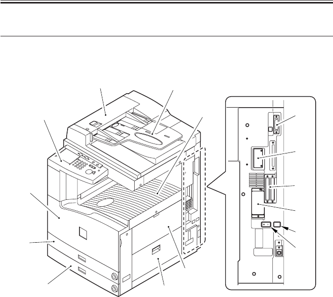
2 Names of Parts
2.1 External View
[1] [2]
[3]
[4]
[5]
[6]
[7]
[8]
[9]
[10]
[11]
[12]
[13]
[14]
[15]
[9] Right lower cover
[10] DIMM ROM replacement cover
[11] Network card slot
[12] Parallel connector
[13] Extension board slot
[14] Main power switch
[15] Cassette heater switch
F01-201-01
[1] ADF
[2] Original tray
[3] Control panel
[4] Front cover
[5] Cassette 1
[6] Cassette 2
[7] Delivery tray
[8] Multifeeder
COPYRIGHT
©
2001 CANON INC. 2000 2000 2000 2000 CANON iR2200/iR2800/iR3300 REV.0 MAR. 2001
CHAPTER 1 GENERAL DESCRIPTION
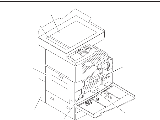
1-10 S
[1] Copyboard glass
[2] DADF reading glass
[3] Left cover
[4] Left lower rear cover (waste toner
case cover)
[5] Developing assembly releasing
lever
[6] Feeding assembly releasing lever
[7] Duplex feeding assembly releas-
ing lever
F01-201-02
[3]
[2]
[1]
[4] [7]
[5]
[6]
COPYRIGHT
©
2001 CANON INC. 2000 2000 2000 2000 CANON iR2200/iR2800/iR3300 REV.0 MAR. 2001
CHAPTER 1 GENERAL DESCRIPTION
1-11 S
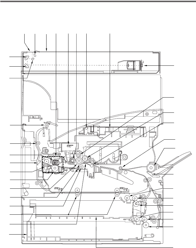
2.2 Cross Section
F01-202-01
[1] [5] [7] [9] [11][12][8] [10]
[27]
[6]
[13]
[15]
[17]
[22]
[18]
[24]
[19]
[32]
[26]
[25]
[29]
[28]
[23]
[30]
[34]
[37]
[35]
[4]
[2]
[3]
[33]
[31]
[14]
[21]
[20]
[36]
[16]

COPYRIGHT
©
2001 CANON INC. 2000 2000 2000 2000 CANON iR2200/iR2800/iR3300 REV.0 MAR. 2001
CHAPTER 1 GENERAL DESCRIPTION
1-12 S
[1] DADF reading glass
[2] No. 1 mirror
[3] No. 2 mirror
[4] No. 3 mirror
[5] Scanning lamp
[6] CCD unit
[7] Copyboard glass
[8] Fixing assembly
[9] Pre-exporsure lump
[10] Laser unit
[11] Laser mirror
[12] Drum cleaner assembly
[13] Primary charging assembly
[14] Photosensitive drum
[15] Developing cylinder
[16] Transfer guide
[17] Multifeeder pickup roller
[18] Multifeeder separation pad
[19] Registration roller
T01-202-01
[20] Transfer roller
[21] Static eliminator
[22] Cassette 1
[23] Cassette 2
[24] Cassette 1 pickup roller
[25] Cassette 1 feeding roller
[26] Cassette 1 separation roller
[27] Cassette 2 pickup roller
[28] Cassette 2 feeding roller
[29] Cassette 2 separation roller
[30] Fixing film
[31] Lower fixing roller
[32] Pre-transfer roller
[33] Fixing delivery roller
[34] Outside delivery roller
[35] Delivery roller
[36] Duplexing roller
[37] Reversing frapper
COPYRIGHT
©
2001 CANON INC. 2000 2000 2000 2000 CANON iR2200/iR2800/iR3300 REV.0 MAR. 2001
CHAPTER 1 GENERAL DESCRIPTION
1-13 S
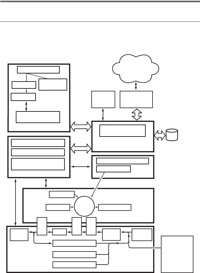
3 System Configuration
3.1 Functional Construction
The machine may be broadly divided into the following six functional blocks:
F01-301-01
Control
panel
DC controller PCB
Main power supply PCB
Conposit power supply
PCB
Main controller PCB
CCD PCB
Laser driver PCB
Reader controller
PCB
Laser scanner
Original
Original
illumination
Charging
Development
Transfer
Pickup
control Multi-
feeder
Cleaning
Duplexing assembly
Cassette 1
Delivery
tray
Feeding
Separation
Fixing
Photo-
sensitive
drum
Cassette 2
HDD
Original Exposure Block
System control/
Image Processing Block
Laser
Exposure Block
Pickup/Feeding Block
Image Formation Block
Control Block
Various
accessory
boards
Side paper
deck
(accessory)
Optical path
Various
networks or public
telephone
network
COPYRIGHT
©
2001 CANON INC. 2000 2000 2000 2000 CANON iR2200/iR2800/iR3300 REV.0 MAR. 2001
CHAPTER 1 GENERAL DESCRIPTION
1-14 S
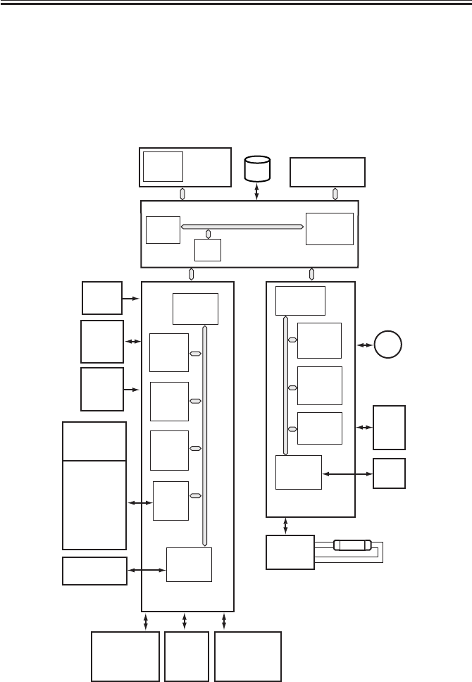
3.2 Outline of the Electrical Circuitry
3.2.1 Construction of the Electrical Circuit
The major electrical mechanisms of the machine are controlled by the following PCBs:
[1] Man controller PCB; controls the system as a whole, processes images
[2] DC controller PCB; controls the printer unit, controls the finisher communication
[3] Reader controller PCB; controls the reader unit, controls the DADF communication
F01-302-01
ADF
LAMP1
M400
CPU
(IC300)
CPU
(IC1010)
SRAM
(IC302)
RAM
IPC
(IC309)
ROM
(IC301)
PIO
(IC303)
ROM
(IC401)
HDD
CPU
(IC6501)
DIMM
ROM
CPU
(IC400)
RAM
(IC402)
EEPROM
(IC403)
GATE
ARRAY
(IC334) IPC
(IC404)
DC controller
PCB
Composite
power
supply
PCB
Drum
sensor
PCB
CCD
PCB
BD
PCB
Scanner
motor
Reader
controller PCB
Main controller PCB
Control
panel
PCB
Inverter
PCB
Main
power
supply
PCB
DC loads
• Clutch
• Solenoid
• Motor
• Sensor
• Fan
• Etc.
Pickup
PCB
Laser
drive
PCB
Finisher
(accessory)
Accessory
boards
Accessories
power
supply
PCB
COPYRIGHT
©
2001 CANON INC. 2000 2000 2000 2000 CANON iR2200/iR2800/iR3300 REV.0 MAR. 2001
CHAPTER 1 GENERAL DESCRIPTION
1-15 S
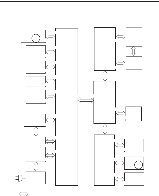
3.3 Inputs to and Outputs from the Major PCBs
3.3.1 Wiring Diagram of the Major PCBs
F01-303-01
Main
controller
PCB
DC
controller
PCB
HDD
BD
PCB
CCD PCB
Feed
PCB
Switch
PCB
Drum
sensor
PCB
Scanner
motor
Conposit
power supply
PCB
Reader
controller
PCB J401
Laser scanner
motor
J4021
J312
J402
Laser
driver
PCB
J307/310
J301
J302
Main
power
supply
PCB
J300
J6
J111
J201
J25
J311
J1015J316
J1025
J2005
J801
J1012
J312
J403/407/408
J409
J1014
J3129
J600/601/602
LCD
panel
(LCD)
Inverter
PCB
Inverter
PCB
Control
panel
CPU PCB
J803
J3
M400
M10
J24
J3114
J1601
J136
J204
J308
J205
J500/501
J3128
Note: The in the diagram indicates connection between PCBs, NOT the flow of signals.

COPYRIGHT
©
2001 CANON INC. 2000 2000 2000 2000 CANON iR2200/iR2800/iR3300 REV.0 MAR. 2001
CHAPTER 1 GENERAL DESCRIPTION
1-16 S
3.4 Configuration with Accessories
3.4.1 Accessories for Original/Paper Feeding
[1] DADF-H1
[2] Platen Cover TypeE
[3] Document Tray-D2
[4] Copy Tray-F1
[5] Saddle Finisher-G1
[6] Puncher Unit-K1/G1/H1
[7] Finisher-J1
[8] Inner 2way Tray-A1
[9] Paper Deck-L1
[10] Cassette Feeding Unit-W1
F01-304-01
[1]
[2]
[5]
[10]
[8]
[7]
[3]
[9]
[4]
[6]
COPYRIGHT
©
2001 CANON INC. 2000 2000 2000 2000 CANON iR2200/iR2800/iR3300 REV.0 MAR. 2001
CHAPTER 1 GENERAL DESCRIPTION
1-17 S
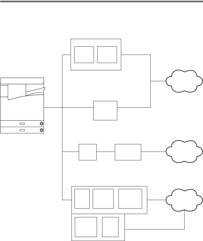
3.4.2 Accessory Boards
F01-304-02
Network Multi-PDL
Printer Kit-C1
Network
PCB
Ethernet Interface
Adapter iN-E3
Token Ring
Network Interface
Adapter iN-TR2
Super G3 FAX Board-J1
Super G3 FAX Expansion Kit-B1
Network
PCB
Boot
ROM
Riser
PCB
Riser Board-A1
TokenRing
PCB
Public
telephone
network
TokenRing
network
Ethernet
network
MODEM
PCB NCU
PCB
FAX
UNIT
PSEUDO
CI
UNIT
SPEAKER
UNIT

COPYRIGHT
©
2001 CANON INC. 2000 2000 2000 2000 CANON iR2200/iR2800/iR3300 REV.0 MAR. 2001
CHAPTER 2
MAIN CONTROLLER
COPYRIGHT
©
2001 CANON INC. 2000 2000 2000 2000 CANON iR2200/iR2800/iR3300 REV.0 MAR. 2001
CHAPTER 2 MAIN CONTROLLER
2-1 S
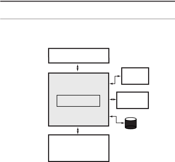
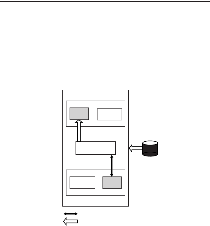
1 Basic Construction
1.1 Functional Construction
The machine may broadly be divided in to the following functional blocks, with the con-
troller block covering the shaded area:
F02-101-01
Control panel
Printer unit
Main controller PCB
Reader unit
HDD
Accessory
boards
Controller unit

COPYRIGHT
©
2001 CANON INC. 2000 2000 2000 2000 CANON iR2200/iR2800/iR3300 REV.0 MAR. 2001
CHAPTER 2 MAIN CONTROLLER
2-2 S
1.2 Outline of the Electrical Circuitry
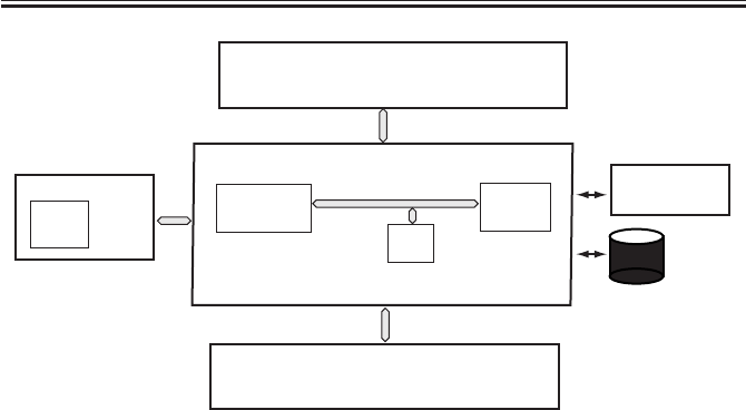
1.2.1 Outline
The major electrical mechanisms of the controller block are controlled by the CPU on the
main controller PCB. The CPU, RAM, DIMM, and the ICs and HDD around the CPU have
the following functions:
1.2.2 Main Controller PCB
Name Description
CPU • Controls the processing of image data from the reader unit.
• Controls the processing of image data to the printer unit.
• Controls the HDD.
• Controls the interface of the following: network, DMA controller, PCI,
and ROM/RAM.
RAM • Stores program data and image data temporarily.
DIMM-ROM • Stores the system control program.
• Stores the boot program.
T02-102-01
1.2.3 HDD
Item Description
HDD • Sores the system software.
• Stores image data for the Box function.
T02-102-02
COPYRIGHT
©
2001 CANON INC. 2000 2000 2000 2000 CANON iR2200/iR2800/iR3300 REV.0 MAR. 2001
CHAPTER 2 MAIN CONTROLLER
2-3 S
F02-102-01
Main controller PCB
Printer unit
Reader unit
Control panel CPU
RAM
Accessory
boards
CPU
DIMM-ROM
HDD
COPYRIGHT
©
2001 CANON INC. 2000 2000 2000 2000 CANON iR2200/iR2800/iR3300 REV.0 MAR. 2001
CHAPTER 2 MAIN CONTROLLER
2-4 S
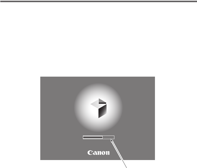
1.3 Start-Up Sequence
1.3.1 Outline
The system software used to control the machine is stored on the machine’s HDD. The
CPU on the main controller PCB reads the system software from the HDD into the SDRAM
fitted to the DIMM socket of the main controller PCB.The control panel displays the follow-
ing screen while the CPU reads the system software from the HDD to the SDRAM, and the
progressive bar on the screen indicates the progress of the start-up sequence.
Start-Up Screen
F02-103-01
Progressive bar
Wait…
COPYRIGHT
©
2001 CANON INC. 2000 2000 2000 2000 CANON iR2200/iR2800/iR3300 REV.0 MAR. 2001
CHAPTER 2 MAIN CONTROLLER
2-5 S
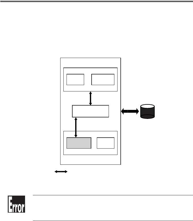
1.3.2 Start-Up Sequence
When the main power switch is tuned on, the CPU on the main controller CPU executes
the self-diagnostic program stored in the boot ROM.
The self-diagnostic program checks the condition of the SDRAM and the HDD; upon de-
tection of a fault, it will indicate the fact in the control panel in the form of an error
code.
F02-103-02
E601-0000, 0001
Indicates the presence of an error in image transfer information.
E602-0001, 0002
Indicates the presence of an error in write/read operation.
Self-diagnostic
program
Boot
program
Boot ROM
CPU
SDRAM
System
area
Image data
area
Main controller PCB
HDD
access to the program during execution
COPYRIGHT
©
2001 CANON INC. 2000 2000 2000 2000 CANON iR2200/iR2800/iR3300 REV.0 MAR. 2001
CHAPTER 2 MAIN CONTROLLER
2-6 S
When the self-diagnostic program ends normally, the boot program also stored in the boot
ROM will start up. The boot program reads the system software from the HDD into the sys-
tem area of the SDRAM.
When the write operation ends, the system software in the SDRAM starts up to initialize
the various parts of the machine, at the end of which the control panel will indicate the nor-
mal operation screen and, at the same time, the Start key LED changes from red to green to
indicate that the machine is ready to accept a job.
The machine’s system software consists of multiple modules, and those modules that are
needed for a specific task in question will be called into the system area of the SDRAM for
use.
F02-103-03
CPU
SDRAM
HDD
:
access to the program during execution.
:
flow of the system program.
Self-diagnostic
program
Boot
program
Boot ROM
System
area
Image data
area
Main controller PCB
COPYRIGHT
©
2001 CANON INC. 2000 2000 2000 2000 CANON iR2200/iR2800/iR3300 REV.0 MAR. 2001
CHAPTER 2 MAIN CONTROLLER
2-7 S
2 Digital Image Processing
2.1 Outline
The machine’s digital image processing and image memory are controlled by the main
controller PCB. The following is a block diagram of digital image processing:
F02-201-01
8
Reader unit Image data after
shading
Editing
Density conversion
(LUT)
Binary processing
(error diffusion method)
(text, text/photo, print photo)
Image memory
control
Binary processing
(dither screen method)
(film photo)
8
Density correction
(γ conversion)
8
8
8
Edge emphasis
1
Compression/de-compression,
rotation, enlargement/reduction
SDRAM
I/O control HDD
Image server
4 or 2
1
Smoothing
1
Binary-binary processing density conversion
Printer unit
Printer PG
1
8
8
Main controller unit
Density adjustment
(F value conversion)
Intensity/density conversion
(LOG conversion)
Enlargement/reduction
(main scanning direction)
Reader PG

COPYRIGHT
©
2001 CANON INC. 2000 2000 2000 2000 CANON iR2200/iR2800/iR3300 REV.0 MAR. 2001
CHAPTER 2 MAIN CONTROLLER
2-8 S
2.2 Input Image Processing
The image data from the reader unit is processed for the following:
2.2.1 Image Data from the Reader Unit
The image signals from the reader unit are 8-bit, 256-gradation intensity image signals
which have been subjected to shading correction.
The signals arrive from two signal lines (for even- and odd-numbered pixels).
2.2.2 Enlargement/Reduction (main scanning direction)
An image is enlarged or reduced by processing image data when writing it into or reading
it from image memory.
2.2.3 Edge Emphasis
For each mode (text, text/photo, print photo, film photo), edge emphasis is executed so as
to increase sharpness while suppressing moire.
2.2.4 Editing
The machine provides various editing functions: negative/positive reversal, mirror, fold.
2.2.5 Density Conversion (LUT)
In this block, the intensity image signals are converted into density image signals, and
processing is executed so as to enable the best output density curve for a specific mode in
question.
a. LOG Conversion
Using a LOG conversion table, intensity image signals based on reflected light are con-
verted into density image signals based on density data.
b. Density Adjustment (F-value conversion)
The F-value table most suited to the setting of the Density key in the control panel is used
to adjust the density; it, however, will not be executed in memory copy mode.
c. Density Correction (γγ
γγ
γ conversion)
The γ conversion table best suited to each specific mode (test, text/photo, print photo, film
photo) is used to correct density.

COPYRIGHT
©
2001 CANON INC. 2000 2000 2000 2000 CANON iR2200/iR2800/iR3300 REV.0 MAR. 2001
CHAPTER 2 MAIN CONTROLLER
2-9 S
2.2.6 Binary Processing (error diffusion method T-BIC)
In the error diffusion method (T-BIC), the texture is controlled to process the data for op-
timum printing effects; 8-bit image density signals of each mode (text, text/photo, print
photo) are converted into 1-bit image density signals (binary).
2.2.7 Binary (dither screen method)
In the dither screen method, the texture is controlled to process the data for optimum
printing effects; 8-bit image density signals for film photo mode are converted into 1-bit im-
age density signals (binary).
Although expressed in binary, the resulting signals enable reproduction in 256 gradations
(dither screening of 40×40 pixels).
2.3 Image Memory Control
The image data after binary processing is controlled for the following:
2.3.1 Compression/De-Compression, Rotation, and Enlargement/Reduc-
tion
The binary data generated as the result of the foregoing processes is subjected to the fol-
lowing: compression/de-compression (for electronic sorting), rotation, resolution conver-
sion.
2.3.2 SDRAM
The image data subjected to image memory control is temporarily stored in SDRAM.
2.3.3 HDD
The HDD functioning as an image server is used to store image data for the Box function.

COPYRIGHT
©
2001 CANON INC. 2000 2000 2000 2000 CANON iR2200/iR2800/iR3300 REV.0 MAR. 2001
CHAPTER 2 MAIN CONTROLLER
2-10 S
2.4 Output Image Processing
The output image data to the printer unit is subjected to the following processing:
2.4.1 Smoothing
a. When Generating Read Images
In the case of text or test/photo mode, the input image of 600×600 dpi is converted into
1200*×600 dpi by means of smoothing.
*Equivalent.
In smoothing, image data is compared against a template consisting of several combina-
tions of pattern matrixes for replacement of selected pixels.
In addition, notch processing is also executed at the same time as a pattern unique to read
image.
b. When Generating Printer (PDL) Images
The image data is subjected to the type of smoothing best suited to PDL, in which
600×600 dpi is converted into 2400*×600 dpi.
*Equivalent.
2.4.2 Binary-Binary Density Conversion (read image output only)
This processing is used as an auxiliary means for adjusting the density of images.

COPYRIGHT
©
2001 CANON INC. 2000 2000 2000 2000 CANON iR2200/iR2800/iR3300 REV.0 MAR. 2001
CHAPTER 2 MAIN CONTROLLER
2-11 S
3 Soft Counters
The machine is equipped with soft counters that count the number of prints it has
handled; the counter readings may be checked by pressing the Check key in the control
panel.
The counters are controlled by the main controller PCB, and each count is incremented
when any of the following sensors detects paper during copy/print operation:
When No Delivery Option Is Installed
Copy/print operation Sensor used Delivery slot
Single-sided PS15 No. 1 delivery sensor Below the inside tray
Double-sided 1st side PS18 Duplexing unit outlet sensor
2nd side PS15 No. 1 delivery sensor Below the inside tray
When the Inner 2-Way Tray Is Used
Copy/print operation Sensor used Delivery slot
Single-sided PS19S No. 2 delivery sensor Above the inside tray
PS21S No. 3 delivery sensor Outside tray
PS18 Duplexing unit outlet sensor
Double-sided 1st side PS19S No. 2 delivery sensor Above the inside tray
2nd side PS21S No. 3 delivery sensor Above the inside tray
2nd side PS21S No. 3 delivery sensor Outside tray
When a Finisher Is Installed
Copy/print operation Sensor used Delivery slot
Single-sided S2 Inlet sensor Finisher delivery tray
Double-sided 1st side PS18 Double-sided outlet sensor
2nd side S2 Inlet sensor Finisher delivery tray
When Delivery Is to the Saddle finisher
Copy/print operation Sensor used Delivery slot
Single-sided PI1 Inlet sensor Finisher delivery tray
Double-sided 1st side PS18 Double-sided outlet sensor
2nd side PI1 Inlet sensor Finisher delivery tray
T02-301-01
COPYRIGHT
©
2001 CANON INC. 2000 2000 2000 2000 CANON iR2200/iR2800/iR3300 REV.0 MAR. 2001
CHAPTER 2 MAIN CONTROLLER
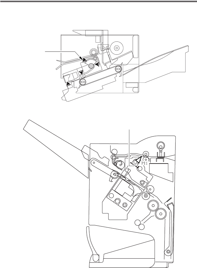
2-12 S
The following diagrams show the locations of the sensor in the finisher and the saddle fin-
isher:
F02-301-01
F02-301-02
Inlet sensor(S2)
Inlet sensor (PI1)

COPYRIGHT
©
2001 CANON INC. 2000 2000 2000 2000 CANON iR2200/iR2800/iR3300 REV.0 MAR. 2001
CHAPTER 2 MAIN CONTROLLER
2-13 S
The counters possess a total of 16 modes, consisting of eight modes for large-size papers
and eight modes for small-size papers; the following shows the basic counter modes:
Copy/print mode Large-size Small-size*
Local copy A B
PDL print C D
Box print E F
Remote copy print G H
Fax receive print I J
Report print K L
Double-sided print M N
Scan O P
*At time of shipment, B4 or smaller; may be changed in service mode to count B4 as large-size.
T02-301-02
The following shows the counter configurations according to mode at time of shipment:
Counter Description*1 Default display Default switch *2
100V model 120/230V model
Counter 1 Total (A through L) ON ON Fixed
Counter 2 Total large (ACEGIK) OFF ON May be changed.
Counter 3 Copy 1 (ABGH) OFF ON May be changed.
Counter 4 Copy 1 large (AG) OFF ON May be changed.
Counter 5 Print 1 total (CDEF) OFF OFF May be changed.
Counter 6 Fax total (IJ) OFF OFF May be changed.
*1:The notations in the parentheses indicate the corresponding basic counter modes (T02-300-20).
*2:The counter description may be changed or enabled/disabled for display in service mode (except
counter 1, whose setting cannot be cannot be changed).
T02-301-03

COPYRIGHT
©
2001 CANON INC. 2000 2000 2000 2000 CANON iR2200/iR2800/iR3300 REV.0 MAR. 2001
CHAPTER 2 MAIN CONTROLLER
2-14 S
OPTION>USER>COUNTER1
Use it to enable/disable the display of soft counter 1 in the control panel.
OPTION>USER>COUNTER2
Use it to enable/disable the display of soft counter 2 in the control panel, or
to change the counter type.
OPTION>USER>COUNTER3
Use it to enable/disable the display of soft counter 3 in the control panel, or
to change the counter type.
OPTION>USER>COUNTER4
Use it to enable/disable the display of soft counter 4 in the control panel, or
to change the counter type.
OPTION>USER>COUNTER5
Use it to enable/disable the display of soft counter 5 in the control panel, or
to change the counter type.
OPTION>USER>COUNTER6
Use it to enable or disable the display of soft counter 6 in the control panel,
or to change the counter type.

COPYRIGHT
©
2001 CANON INC. 2000 2000 2000 2000 CANON iR2200/iR2800/iR3300 REV.0 MAR. 2001
CHAPTER 2 MAIN CONTROLLER
2-15 S
4 Controlling the Power Supply
4.1 Outline
In addition to its control in response to the operation of the main power switch, the main
controller PCB possesses the following control mechanisms in relation to the power supply:
• Standby mode (normal operation)
• Sleep mode 1
• Sleep mode 2
4.2 Power Supply Modes
The machine has the following modes for each of its power supply mechanisms; +3.3V
all-night (3.3 VB), +3.3V non-all night (3.3 VA), +5V, and 24V:
Mode +3.3V all night +3.3V non-all night +5V +24V LCD
Standby Yes Yes Yes Yes Yes
Sleep mode 1 Yes Yes Yes Yes No
Sleep mode 2 Yes No No No No
T02-402-01
4.3 Standby Mode (normal operation)
In standby mode, the machine is in operation or is ready operate, and nearly all compo-
nents are supplied with power; not only the main controller PCB, but also the reader unit,
printer unit, and control panel are all ready for communication and control.
4.4 Sleep Mode 1
In sleep mode 1, only the LCD image desplay remains OFF.

COPYRIGHT
©
2001 CANON INC. 2000 2000 2000 2000 CANON iR2200/iR2800/iR3300 REV.0 MAR. 2001
CHAPTER 2 MAIN CONTROLLER
2-16 S
4.4.1 Shift from Standby Mode to Sleep Mode 1
A shift from standby mode to sleep mode 1 is executed for the following:
• The power switch (soft switch) in the control panel is OFF.
• The machine remains in standby mode and a specific period of time (may be changed in
user mode) has passed.
In addition, the following must be true:
• The setting of 'Function key wakeup ON/OFF' under 'Common settings' in user mode is
set to 'ON'.
• The setting of 'Energy consumption in Sleep Mode' under 'Common settings' in user
mode is set to 'high'.
• The setting of 'NetWare settings' under 'Network settings' in user mode is set to 'ON'.
• The setting of 'AppleTalk settings' under 'Network settings' in user mode is set to ON'.
• The setting of 'DHCP' under 'IP Address / TCP/IP settings' in user mode is set to use.
• A TokenRing board is installed.
• In the fax, timer transmission is selected.
• In the fax, an auto start job is selected.
• An extension of the fax is in use (engaged).
4.4.2 Shift from Sleep Mode 1 to Standby Mode
A shift from sleep mode 1 to standby mode is expected for the following:
• The power switch (soft switch) in the control panel is turned on.

COPYRIGHT
©
2001 CANON INC. 2000 2000 2000 2000 CANON iR2200/iR2800/iR3300 REV.0 MAR. 2001
CHAPTER 2 MAIN CONTROLLER
2-17 S
4.5 Sleep Mode 2
In sleep mode 2, only the +3.3V all-night (3.3 VB) power supply is ON. The CPU on the
main control paper remains in wait for an interrupt (keeping the program at rest) to limit the
consumption of power.
4.5.1 Shift from Standby Mode to Sleep Mode 2
A shift from standby mode to sleep mode 2 is executed under the following:
• The power switch (soft switch) in the control panel is OFF.
• The machine has remained in standby mode for a specific period of time (may be
changed in user mode).
4.5.2 Shift from Sleep Mode 2 to Standby Mode
A shift from sleep mode 2 to standby mode is executed for the following:
• The power switch (soft switch ) in the control panel is ON.
4.5.3 Shift from Sleep Mode 2 to Sleep Mode 1
A shift from sleep mode 2 to sleep mode 1 is executed for the following:
• PDL data is received from the network or from the parallel port.
4.6 Turning Off the Power
The power is turned off when the main power switch is turned off. A shift from this state
may be made only by turning on the main power switch; the shift will be automatic and to
standby mode.

COPYRIGHT
©
2001 CANON INC. 2000 2000 2000 2000 CANON iR2200/iR2800/iR3300 REV.0 MAR. 2001
CHAPTER 2 MAIN CONTROLLER
2-18 S
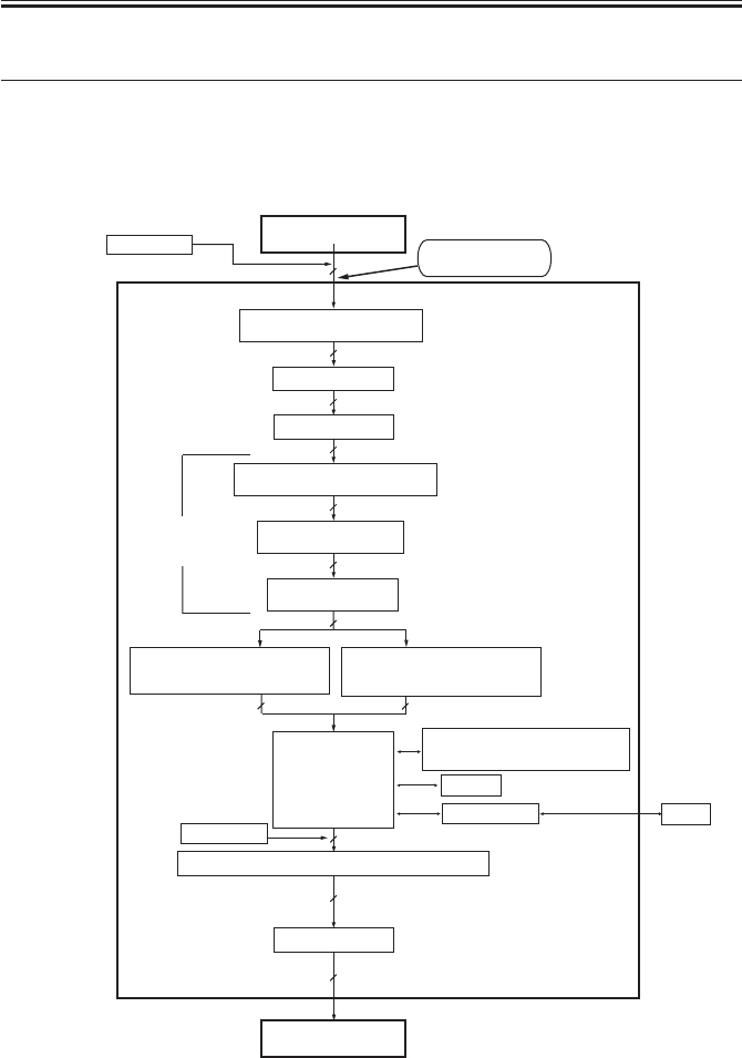
5 New Functions
5.1 Hard Disk Spool
In hard disk spool, print data is not directly sent to memory for printing, but spooled on
the HDD before printing, thus releasing the application program running on the host PC
sooner than otherwise.
When this function is used, a print job from the PC is stored in the spool area of the
HDD. (The spool area is as large as about 300 MB.) Once spooled, the jobs are then sent to
the RIP processing block in the order they have been received.
The jobs are removed from the spool as they are printed, and as many as 100 jobs may be
spooled at a time.
The following diagram shows the flow of data, from spooling on the HDD to execution:
F02-501-01
Main controller PCB
De-compression
circuit
Printer unit
RIP
processing
block
Memory for
development
HDD
Spool area
Print
buffer
area
(1)PDL data
(2)PDL data
(3)PDL data (4)Image data
(6)Compression data
(5)Image data
(7)Binary data
(8)Binary data
(9)Binary data
(10)Binary data
(11)Binary data
(12)Image date
Page
memory
for printing
Network PCB
Print image
processing block
job 1
job 2
job n
Compression
circuit
COPYRIGHT
©
2001 CANON INC. 2000 2000 2000 2000 CANON iR2200/iR2800/iR3300 REV.0 MAR. 2001
CHAPTER 2 MAIN CONTROLLER
2-19 S
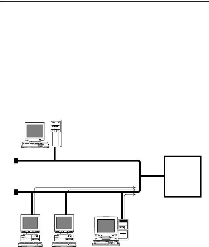
5.2 SMB Printing
SMB has been developed so as to use NetBIOS, which specifies an address by means of a
computer name, for use solely with a specific protocol. SMB over TCP/IP is designed for
use in combination with the TCP/IP protocol, enabling the machine to print data directly
from Windows 95/98/ME without going through a Windows NT/2000 sever as is in the case
of LPR printing and without the need for an LPR utility. (A Windows work group may be
made use of, but Windows NT/2000 cannot be called into the domain.)
On a TCP/IP network an address must be specified by means of an IP address, not the
name of the computer in question, requiring conversion of a computer name into an IP ad-
dress. If a WINS (Windows Internet Name Service) server exits on the network, the function
may also be made use of. If it does not exist or is not used, the PC will contact all devices
on the network to find out the IP address of the machine before it sends a print job to the
machine.
F02-502-01
WINS server
Windows 95/98
Protocol:TCP/IP
Ethernet
Windows 95/98Windows 95/98
Service:SMB
iR2200
iR2800
iR3300

COPYRIGHT
©
2001 CANON INC. 2000 2000 2000 2000 CANON iR2200/iR2800/iR3300 REV.0 MAR. 2001
CHAPTER 2 MAIN CONTROLLER
2-20 S
5.3 LPD Banner
When OPD printing is selected, the following job information will be printed:
LPD Banner (sample)
iR2200-3300 (iN-E2)
USER NAME : ts
HOST NAME : canon
JOB NAME : golfer.ps
F02-503-01

COPYRIGHT
©
2001 CANON INC. 2000 2000 2000 2000 CANON iR2200/iR2800/iR3300 REV.0 MAR. 2001
CHAPTER 3
INSTALLATION

COPYRIGHT
©
2001 CANON INC. 2000 2000 2000 2000 CANON iR2200/iR2800/iR3300 REV.0 MAR. 2001
CHAPTER 3 INSTALLATION
3-1 S
1 Selecting the Site of Installation
Select the site of installation against the following conditions; if possible, visit the user’s
in advance of the delivery of the machine:
1. There must be a power outlet that may be used exclusively for the machine and rated as
indicated (±10%).
2. The temperature of the room must be between 7.5° and 30°C (59° and 86°F) and humid-
ity, between 5% and 80%. Avoid areas near a water faucet, water boiler, humidifier, or
refrigerator.
3. The site must not be near a source of fire or must not be subject to dust or ammonium
gas. If the site is exposed to direct rays of the sun, provide curtains.
4. The level of ozone generated by the machine in operation will not affect the health of
the individuals around it. Nevertheless, some may find the odor unpleasant, requiring
good ventilation of the work place.
5. The floor of the site must be level so that the feet of the machine will remain in contact
and the machine itself will remain level.
COPYRIGHT
©
2001 CANON INC. 2000 2000 2000 2000 CANON iR2200/iR2800/iR3300 REV.0 MAR. 2001
CHAPTER 3 INSTALLATION
3-2 S
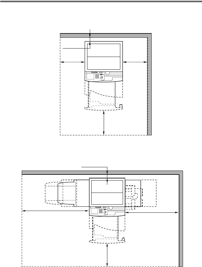
6. The site must be such that the machine will be at least 10 cm away from any wall, allow-
ing adequate space for work.
F03-100-01
F03-100-02
7. The site must be well ventilated. Do not install the machine near the air inlet of the
room.
10 cm min.
50 cm min.
50 cm min.50 cm min.
10 cm min.
100 cm min.
110 cm min.
50 cm min.

COPYRIGHT
©
2001 CANON INC. 2000 2000 2000 2000 CANON iR2200/iR2800/iR3300 REV.0 MAR. 2001
CHAPTER 3 INSTALLATION
3-3 S
2 Unpacking and Installation
2.1 Before Starting the Work
Keep the following in mind for the work:
1. If the machine is brought in from a cold to warm place, its pickup/feed-
ing assembly can develop condensation, leading to image faults. Leave
the machine alone for at least one hour, and start the work after the ma-
chine has become used to the room temperature.
The term condensation refers to the symptom that occurs when a piece of
metal is brought in from a cold to warm place, cooling the vapor in the
air rapidly and turning it into droplets of water on the metal surface.
2. The machine weighs about 80 kg. Be sure to work in a group of four.
COPYRIGHT
©
2001 CANON INC. 2000 2000 2000 2000 CANON iR2200/iR2800/iR3300 REV.0 MAR. 2001
CHAPTER 3 INSTALLATION
3-4 S
2.2 Unpacking and Removing the Fixing Materials
Work Checks/remarks
1) Open the shipping box, and remove the
plastic sheets.
• If you are installing the pedestal at the
same time, unpack it.
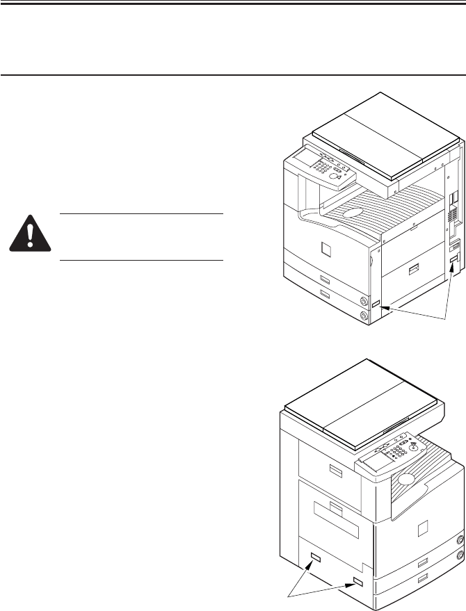
2) While working in a group of four, hold
the grips [1], and place it on the pedes-
tal. (weight of body: about 80kg)
Take care so that the main
power switch will not be turned
on when the machine is lifted.
[1]
[1]
COPYRIGHT
©
2001 CANON INC. 2000 2000 2000 2000 CANON iR2200/iR2800/iR3300 REV.0 MAR. 2001
CHAPTER 3 INSTALLATION
3-5 S
Work Checks/remarks
3) Remove the packing tape of the ma-
chine.
4) Press the cassette release button, and
take out each cassette to the front.
5) Connect the machine and the pedestal
using a screw [1].
Other types of pedestal may
also be connected using a screw.
6) Slide the cassettes into the machine.
7) Open the cardboard box that comes
with the machine, and take out the com-
ponents and attachments; check to make sure that none of the fol-
lowing is missing:
• User’s Manual
• Drum unit
• Right lower cover
• Cassette size label (inside cassettes)
• Cassette size plate (inside cassette)
• Guidebook (model w/ printer function
only)
• CD-ROM (model w/ printer function
only)
[1]
COPYRIGHT
©
2001 CANON INC. 2000 2000 2000 2000 CANON iR2200/iR2800/iR3300 REV.0 MAR. 2001
CHAPTER 3 INSTALLATION
3-6 S
2.3 Mounting the Scanner
Work Checks/remarks
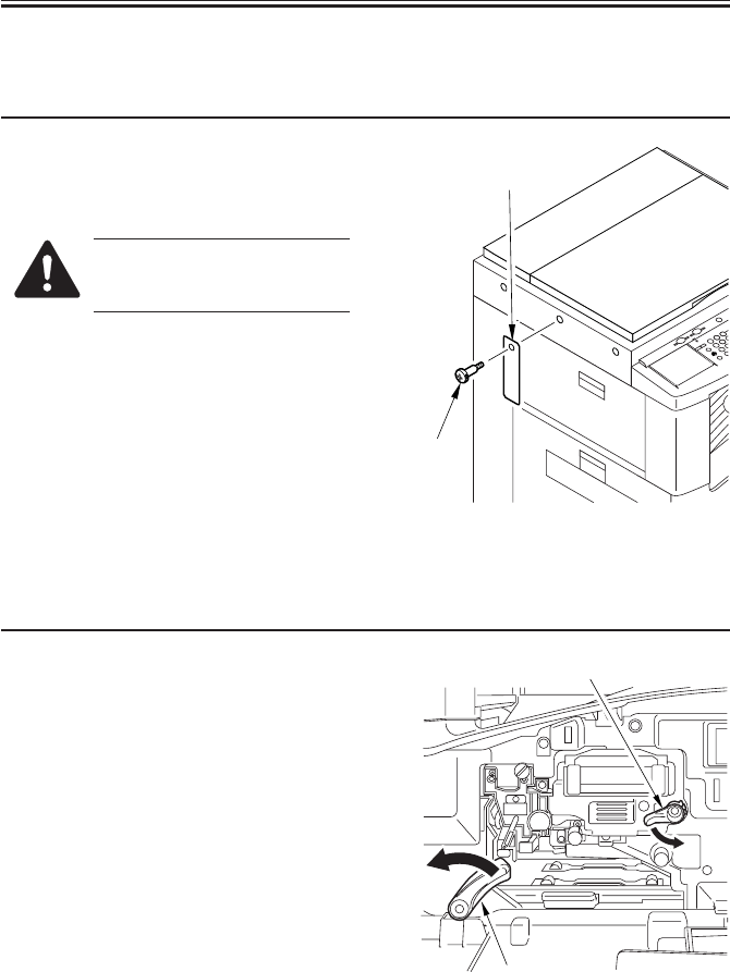
1) Remove the screw [1] and the tag [2]
used to hold the scanner in place on the
left cover of the reader unit.
Keep the screw stored away for
possible relocation of the ma-
chine.
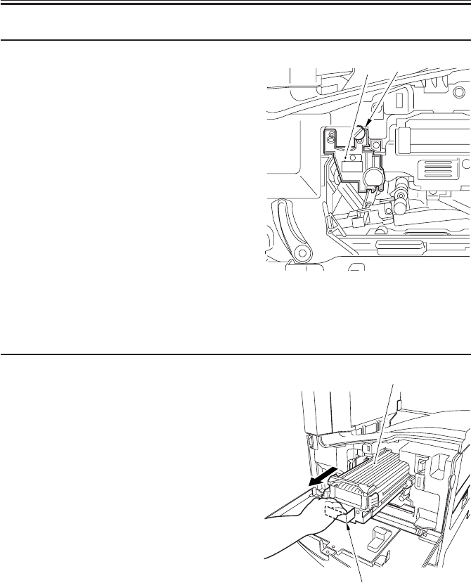
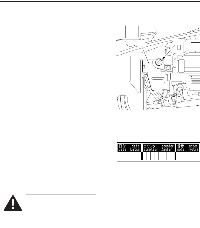
2.4 Removing the Dummy Drum
Work Checks/remarks
1) Open the front cover.
2) Shift down the feeder releasing lever [1]
to release the feeding assembly.
3) Turn the developing assembly locking
lever [2] counterclockwise to free the
developing assembly.
[2]
[1]
[2]
[1]
COPYRIGHT
©
2001 CANON INC. 2000 2000 2000 2000 CANON iR2200/iR2800/iR3300 REV.0 MAR. 2001
CHAPTER 3 INSTALLATION
3-7 S
Work Checks/remarks
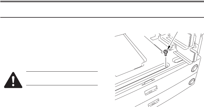
4) Remove the fixing screw [1] from the
dummy drum.
• The removed fixing screw will be used
when mounting the drum unit.
5) Pull the dummy drum [2] straight out to
the font.
• The removed dummy drum will no
longer be used.
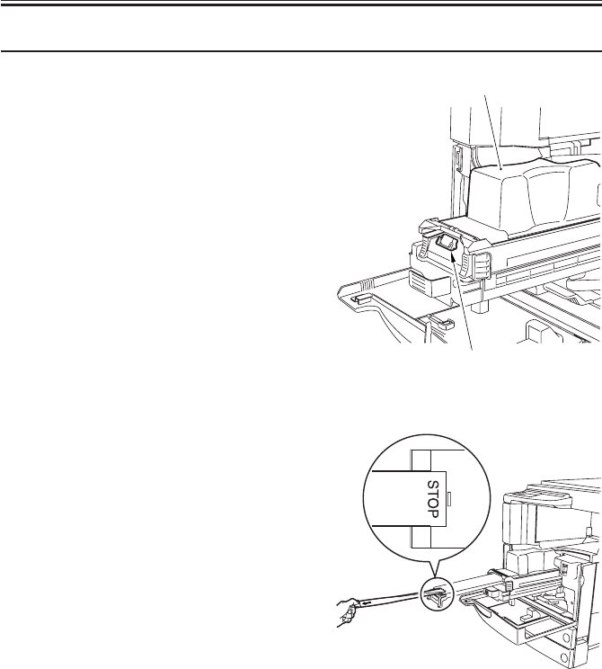
2.5 Supplying the Toner
Work Checks/remarks
1) Holding the grip [1] of the developing
assembly, pull the developing assembly
[2] to the front until it stops.
[2] [1]
[2]
[1]
COPYRIGHT
©
2001 CANON INC. 2000 2000 2000 2000 CANON iR2200/iR2800/iR3300 REV.0 MAR. 2001
CHAPTER 3 INSTALLATION
3-8 S
Work Checks/remarks
2) Shake the toner cartridge [1] several
items.
3) Set the toner cartridge to the developing
assembly, and push it down until the
opening tab [2] springs to view.
• The toner cartridge is locked to the de-
veloping assembly.
4) While lightly holding down the toner
cartridge with one hand, pull the open
tab to the front until it stops (where the
marking STOP is found).
5) Tap lightly on the top of the toner car-
tridge so that all toner will drop.
[1]
[2]
COPYRIGHT
©
2001 CANON INC. 2000 2000 2000 2000 CANON iR2200/iR2800/iR3300 REV.0 MAR. 2001
CHAPTER 3 INSTALLATION
3-9 S
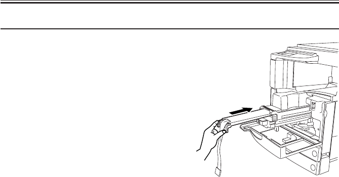
Work Checks/remarks
6) Push in the black cover of the develop-
ing assembly back to its initial position.
• The toner cartridge will become disen-
gaged.
7) Remove the toner cartridge.
8) Push in the developing assembly until it
butts against the rear.
COPYRIGHT
©
2001 CANON INC. 2000 2000 2000 2000 CANON iR2200/iR2800/iR3300 REV.0 MAR. 2001
CHAPTER 3 INSTALLATION
3-10 S
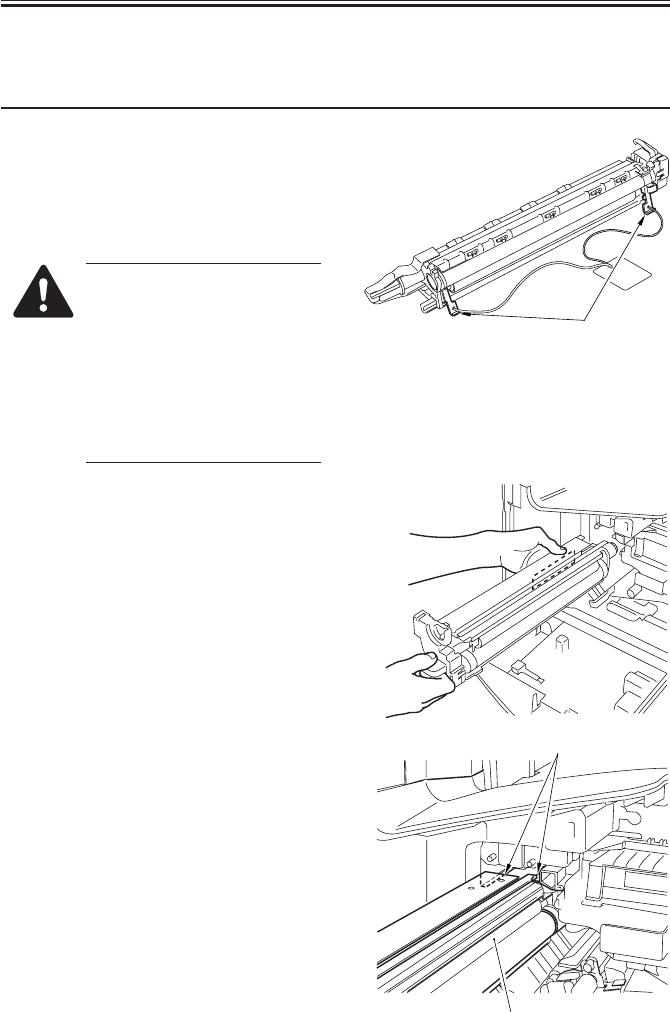
2.6 Mounting the Drum Unit
Work Checks/remarks
1) Unpack the drum unit, and remove the
two releasing members [1] of the pri-
mary charging roller.
Remove all other packing tape and the
like.
1. Do not touch the dump area
of the photosensitive drum to
avoid damage.
2. Take care not to expose the
photosensitive drum to strong
light.
3. Take care not to damage the
stirrups found at the bottom
of the drum unit.
2) Check to make sure that the developing
assembly is released; then, holding the
drum unit [1] by its long hole, slide in-
side the machine along the rails [2].
At this time, take full care not to bring
the developing assembly in contact with
the developing cylinder, which is situ-
ated nearby.
[1]
[2]
[1]
COPYRIGHT
©
2001 CANON INC. 2000 2000 2000 2000 CANON iR2200/iR2800/iR3300 REV.0 MAR. 2001
CHAPTER 3 INSTALLATION
3-11 S
Work Checks/remarks
3) Using the fixing screw [1] removed
from the dummy drum previously, se-
cure the dump unit [2] in place.
4) Fill out the date label, and attach it to
the front cover of the drum unit.
5) Turn the developing assembly locking
lever clockwise to lock the developing
assembly in place.
6) Shift up the feeding releasing lever to
lock the feeding assembly in place.
Do not turn on the main power
switch while the feeding assem-
bly remains released; otherwise,
the fixing assembly will be
damaged.
7) Close the front cover.
[2] [1]
COPYRIGHT
©
2001 CANON INC. 2000 2000 2000 2000 CANON iR2200/iR2800/iR3300 REV.0 MAR. 2001
CHAPTER 3 INSTALLATION
3-12 S
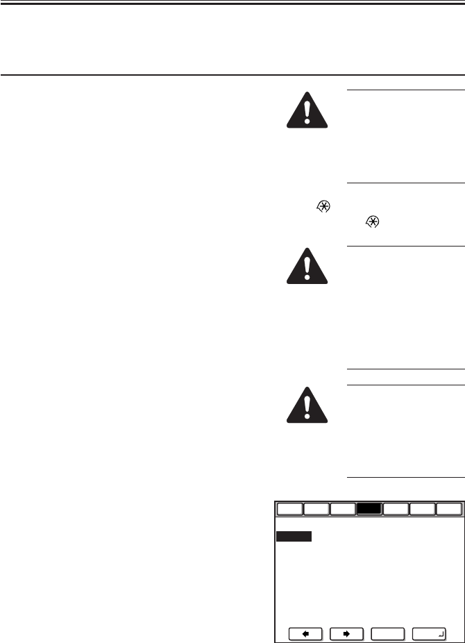
2.7 Stirring the Toner
Work Checks/remarks
1) Connect the power plug to the power
outlet.
2) Turn on the main power switch.
• Wait until the control panel indicates
that the machine is ready for operation.
3) Start service mode.
4) Make the following selections:
COPIER>FUNCTION>INSTALL>TONER-
S.
5) Press the OK key.
• The stirring operation will last for 240
sec (4 min), after which the operation
stops automatically.
6) Press the Reset key twice to end service
mode.
7) Execute 'roller clean' in user mode ('ad-
just/clean'), and execute transfer charg-
ing roller resistance detection control
(ATVC).
Display
Function
I/O Adjust Option Test
Counter
<INSTALL > < 1/ 1 > <NO-PAPER>
TONER-S
Check the Developer
STRD-POS
CARD 0 →( 0) { 1 - 2700}
+/- OK
The power supply
must be as rated. (The
voltage may be ±
10% of the rating, but
it must have the rated
amperage.)
Press the key, ‘2’ and ‘8’ at the
same time, and the key once again.
The following mes-
sage will appear:
“CHECK THE DE-
VELOPER.” In re-
sponse, check to see if
the developing assem-
bly is properly locked
in place.
If you inadvertently
stopped stirring of the
toner in the middle, be
sure to execute
‘TONER-S’ once
again.
COPYRIGHT
©
2001 CANON INC. 2000 2000 2000 2000 CANON iR2200/iR2800/iR3300 REV.0 MAR. 2001
CHAPTER 3 INSTALLATION
3-13 S
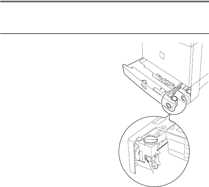
2.8 Setting the Cassette
Work Checks/remarks
1) Press the cassette releasing button, and
slide out the cassette to the front.
2) Check with the user to find out the size
of paper to use, and check the size set-
ting (A/B or Inch) using the selection
switch [1] of each cassette.
[1]

COPYRIGHT
©
2001 CANON INC. 2000 2000 2000 2000 CANON iR2200/iR2800/iR3300 REV.0 MAR. 2001
CHAPTER 3 INSTALLATION
3-14 S
Work Checks/remarks
3) Pick the lever of the side guide plate
and the rear guide plate, and adjust it to
the appropriate paper size index.
The middle cassette cannot hold
A3 or 11×17 paper.
4) Set the paper size dial to suit the se-
lected paper size.
Set the dial as indicated.

COPYRIGHT
©
2001 CANON INC. 2000 2000 2000 2000 CANON iR2200/iR2800/iR3300 REV.0 MAR. 2001
CHAPTER 3 INSTALLATION
3-15 S
Work Checks/remarks
5) Attach the size label [2] to the cassete
size plate [1], and fit the cassette size
plate to each cassette.
6) Put paper into the cassettes [3], and
slide them into the machine.
[2]
[1]
LTR
A4
[3]
COPYRIGHT
©
2001 CANON INC. 2000 2000 2000 2000 CANON iR2200/iR2800/iR3300 REV.0 MAR. 2001
CHAPTER 3 INSTALLATION
3-16 S
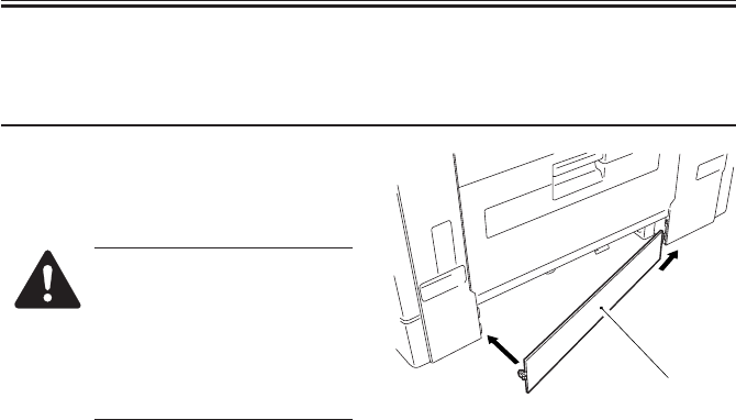
2.9 Checking the Images/Operations
Work Checks/remarks
1) To install the machine not using the 2-
cassette pedestal, mount the right lower
cover [1].
1. Skip this step if the machine
is installed on a 2-cassette
pedestal.
2. After removing the right
lower cover, check to make
sure that the cover is securely
in place.
2) Clean the surface of the reading glass of
the copyboard.
3) Using the NA-3 Chart as the original,
make a print to check the images and
the operation.
4) Make user mode settings (e.g., date,
time) and service mode settings
(COPIER>OPTION>USER) to suit the
needs of the user.
Optimum Image
• In text mode, the white background
must not be foggy.
• In text/photo mode, step edge No. 10
must be barely visible. The white
background must be free of fogging.
• In photo mode, the white background
must be free of fogging. (The moire, if
any, along the step edges and the half-
tone area does not indicate a fault.)
The non-image width must be as indi-
cated: 2.5±1.5 mm.
Checking the Operations
• During copying operation, check to
make sure the operations are normal.
• During double-sided copying opera-
tion, check to make sure that paper is
moved normally in the duplex unit.
• For pickup operation, check to make
sure that pickup from each source of
paper is normal.
• There must not be abnormal operating
noise.
• Make copies at each default reproduc-
tion ratio, and check to make sure that
the images are normal.
• Make copies in multiple sets, and
check to make sure that copies are
made specified numbers.
[1]
COPYRIGHT
©
2001 CANON INC. 2000 2000 2000 2000 CANON iR2200/iR2800/iR3300 REV.0 MAR. 2001
CHAPTER 3 INSTALLATION
3-17 S
Work Checks/remarks
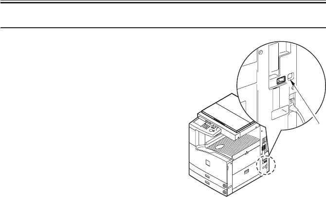
5) If necessary in view of the site environ-
ment, turn on the cassette heater switch
[1].
6) Move the machine to the site of installa-
tion; if it is placed on a pedestal, secure
it in place using the four adjusters.
7) Clean the area around the machine, and
fill out the Service Book.
[1]
COPYRIGHT
©
2001 CANON INC. 2000 2000 2000 2000 CANON iR2200/iR2800/iR3300 REV.0 MAR. 2001
CHAPTER 3 INSTALLATION
3-18 S
2.10 Connecting to the Network
Perform the following steps if the machine is equipped with printer func-
tions:
1) Turn off the main power.
2) Connect the network cable to the machine, and turn on the main power.
3) Inform the user’s system administrator that the machine has been installed, and ask him/
her to make the network settings for the machine.
2.11 Checking the Network Connection
Perform the following steps if the machine is equipped with printer func-
tions:
If the user’s network environment is TCP/IP, use the PING function to make sure that the
network PCB has properly been installed and the network settings have properly been made.
If the user’s network environment is IPX/SPX or AppleTalk, on the other hand, these checks
are not needed.
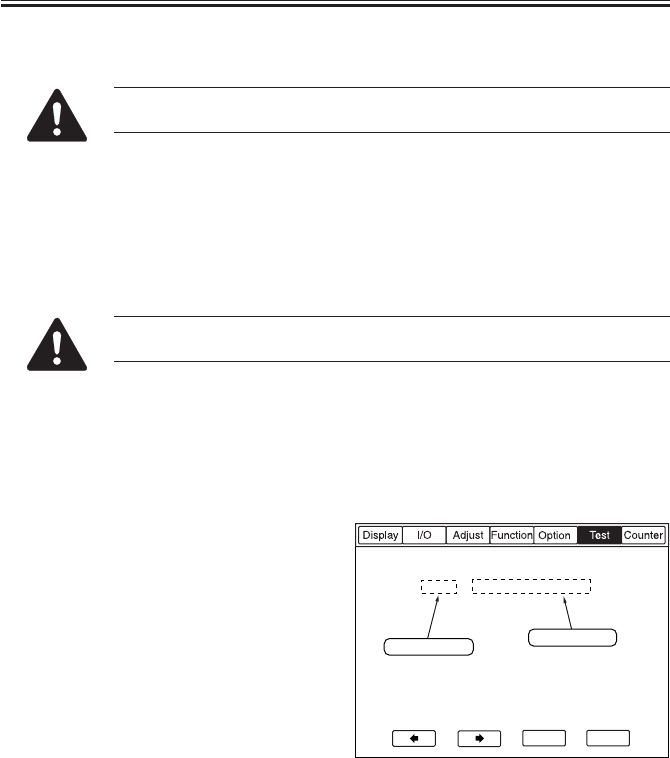
2.11.1 Using the PING Function
1) Make the following selections to select
PING:
COPIER>TEST>PING>NETWORK.
2) Enter the IP address using the keypad
on the control panel, and press the OK
key.
3) Press the Start key.
• If PING is successful, ‘OK’ will be in-
dicated: otherwise, ‘NG’ will be indi-
cated.
0 . 0 . 0 . 0
+/-
OK
<NETWORK> < 1/1 > <READY >
PING
IP address input
Results (OK/NG)

COPYRIGHT
©
2001 CANON INC. 2000 2000 2000 2000 CANON iR2200/iR2800/iR3300 REV.0 MAR. 2001
CHAPTER 3 INSTALLATION
3-19 S
2.11.2 Making a Check Using a Remote Host Address
The connection to the network may be checked by executing PING using a remote host
address (i.e., the IP address of a PC terminal connected to and operating on the TCP/IP net-
work to which the machine is connected).
1) Inform the user’s system adminisrator that the network connection will be checked using
PING.
2) Check with the user’s system administrator to find out the remote host address.
3) Enter the remote host address in the PING field.
• If ‘OK’ is indicated, the connection to the network is correct.
• If ‘NG’ is indicated, the connection to the network is not correct; investigate the cause as
follows:
2.12 Troubleshooting the Network
Perform the following steps if the machine is equipped with printer func-
tions:
If the connection to the network is not made, the following can be suspected; perform the
steps under 2.12.1 to correct the faults:
a. The connection between the network and the network PCB is faulty.
b. The TCP/IP settings on the machine are faulty.
c. The network PCB is faulty, or the PCB is mounted wrongly.
d. The user network is faulty.
2.12.1 Checking the Connection of the Network Cable
1) Check to find out if the network cable is correctly connected to the network PCB.
• If the connection is correct, go to 2.12.2.
• If the connection is wrong, correct it, and make a check once again using the remote
host address.

COPYRIGHT
©
2001 CANON INC. 2000 2000 2000 2000 CANON iR2200/iR2800/iR3300 REV.0 MAR. 2001
CHAPTER 3 INSTALLATION
3-20 S
2.12.2 Making a Check Using a Loop-Back Address
A loop-back address is returned before it reaches the network PCB; therefore, executing
PING using it will enable a check on the TCP/IP settings made on the machine.
1) Enter the loop-back address (127.0.0.1) in the PING field.
• If ‘NG’ is indicated, check the TCP/IP settings of the machine once again, and execute
PING once again.
• If ‘OK’ is indicated, go to 2.12.3.
2.12.3 Making a Check Using a Local Host Address
The local host address is the IP address of the machine, and executing PING using it will
enable a check on the network PCB (it is retuned after it reaches the network PCB).
1) Enter the IP address of the machine in the PING field.
• If ‘NG’ is indicated, perform the following check/correction, and execute PING once
again:
a. If the IP address of the machine is wrong, check the IP address settings made on the ma-
chine once again, or find out if the IP address assigned to the machine is correct or not
by consulting the user’s system administrator.
b. If the network has faulty connection, check the connector of the network PC for connec-
tion.
c. If the network PCB is faulty, replace the network PCB.
• If ‘OK’ is indicated, suspect a problem in the user’s network environment; report to the
user’s system administrator, and ask for corrective measures.

COPYRIGHT
©
2001 CANON INC. 2000 2000 2000 2000 CANON iR2200/iR2800/iR3300 REV.0 MAR. 2001
CHAPTER 3 INSTALLATION
3-21 S
3 Relocating the Machine
3.1 Preparing for Relocation
If the machine must be relocated by truck or other means of transportation after it has
been installed, perform the following:
Do not lift the machine by holding its grips as when moving it over a step;
otherwise, the machine will become separated from the pedestal. Be sure to
lift the pedestal if the machine is connected to it.
Work Checks/remarks
1) Remove the fixing screw, and detach the
drum unit.
2) Fix the scanner in place.
3) Tape the front cover, delivery assembly,
and cassette in place.
4) Place a single sheet of A3/11×17 paper
on the copyboard glass, and tape the
copyboard cover (ADF) in place.
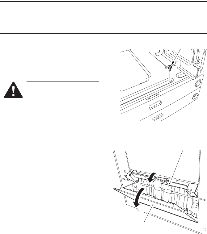
COPYRIGHT
©
2001 CANON INC. 2000 2000 2000 2000 CANON iR2200/iR2800/iR3300 REV.0 MAR. 2001
CHAPTER 3 INSTALLATION
3-22 S
3.2 Lifting the Machine Off the Pedestal
Work Checks/remarks
1) Disconnect the lattice connector of the
pedestal from the machine.
2) Slide out the two cassettes from the ma-
chine, and remove the screw [1] used to
connect the machine to the pedestal.
Remove the screw likewise if
the machine is installed to a dif-
ferent type of cassette pedestal.
3) Open the right cover [1] of the pedestal,
and release the guide assembly [2] con-
nected to the machine (i.e., shift it down
to the right).
4) While working in a group of two or
more, hold the grips of the machine,
and lift it straight up (pay attention to
the pins of the pedestal).
5) Place the machine on the floor or on a
desk.
[1]
[2]
[1]
[B]
[A]
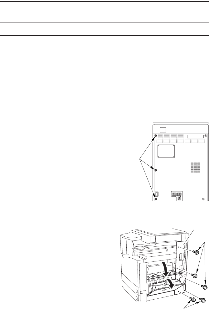
COPYRIGHT
©
2001 CANON INC. 2000 2000 2000 2000 CANON iR2200/iR2800/iR3300 REV.0 MAR. 2001
CHAPTER 3 INSTALLATION
3-23 S
4 Installing the Card Reader-C1
Work Checks/remarks
1) Make the following selections in service
mode:
COPIER>FUNCTION>INSTALL>CARD;
then, enter the card number (1 through
2701).
• Enter the number of the card (of all the
cards used by the user) that have the
lowest number.
• As many as 300 cards may be used hav-
ing a number higher than the one en-
tered.
2) Turn off the main power switch.
3) To facilitate the removal of the right
rear cover, remove the screws [1] from
the rear cover.
4) Open the manual feed tray and the right
lower cover.
5) Remove the five screws [1] ; and, while
opening the right rear cover [2] slightly,
detach the right rear cover.
[1]
[1]
[1]
[2]
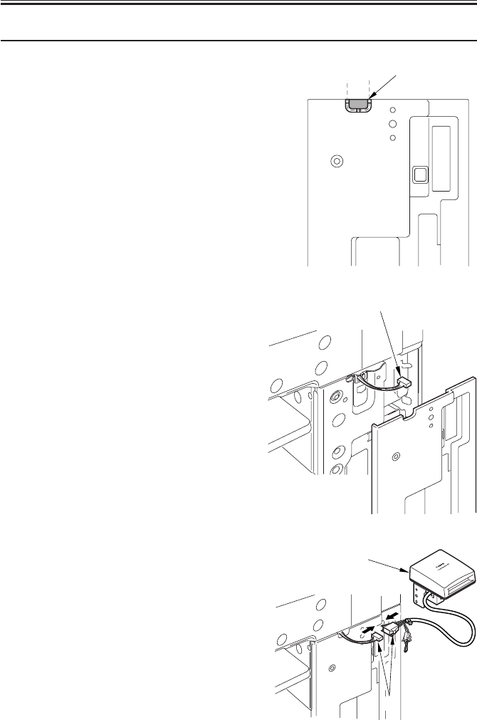
COPYRIGHT
©
2001 CANON INC. 2000 2000 2000 2000 CANON iR2200/iR2800/iR3300 REV.0 MAR. 2001
CHAPTER 3 INSTALLATION
3-24 S
Work Checks/remarks
6) Cut off the face plate [1] at the top of
the right rear cover with a nipper or the
like.
7) Lead out the connector [1] of the card
reader on the machine side, and mount
the right rear cover.
8) Connect the connector [2] on the card
reader [1] side and the connector [2] on
the machine side.
[1]
[1]
[1]
[2]
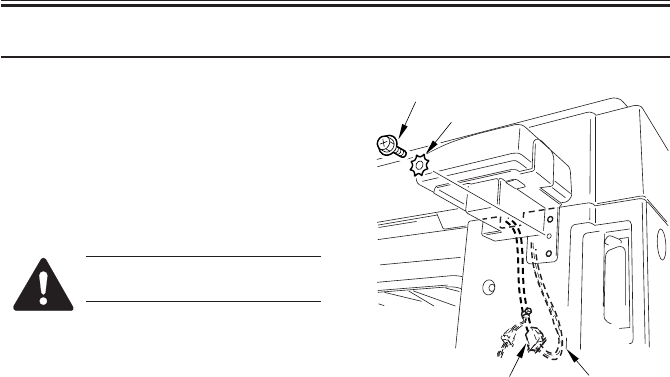
COPYRIGHT
©
2001 CANON INC. 2000 2000 2000 2000 CANON iR2200/iR2800/iR3300 REV.0 MAR. 2001
CHAPTER 3 INSTALLATION
3-25 S
Work Checks/remarks
9) While pushing in the connector [1] and
the harness [2] inside the machine, fit
the boss of the right rear cover into the
opening in the card reader support plate;
then, secure the card reader to the ma-
chine using a screw [3] and a washer
[4].
Take care not to trap the con-
nector or the harness.
[1] [2]
[3] [4]

COPYRIGHT
©
2001 CANON INC. 2000 2000 2000 2000 CANON iR2200/iR2800/iR3300 REV.0 MAR. 2001
CHAPTER 3 INSTALLATION
3-26 S
5 Installing the Document Tray-D2
Work Checks/remarks
1) Remove the two stickers from the right
top of the machine.
Using the two stepped screws [1] (RS
tightening; M4×10) that come with the
machine, mount the document tray [2]
to the machine.
• If the work proves to be difficult, loosen
the two stepped screws, and try again.
1. Be sure to use the stepped
screws designed for the ma-
chine; ones for other types
come together with the ma-
chine.
2. The document tray may be
mounted to the left side of the
machine.
[1] [2]
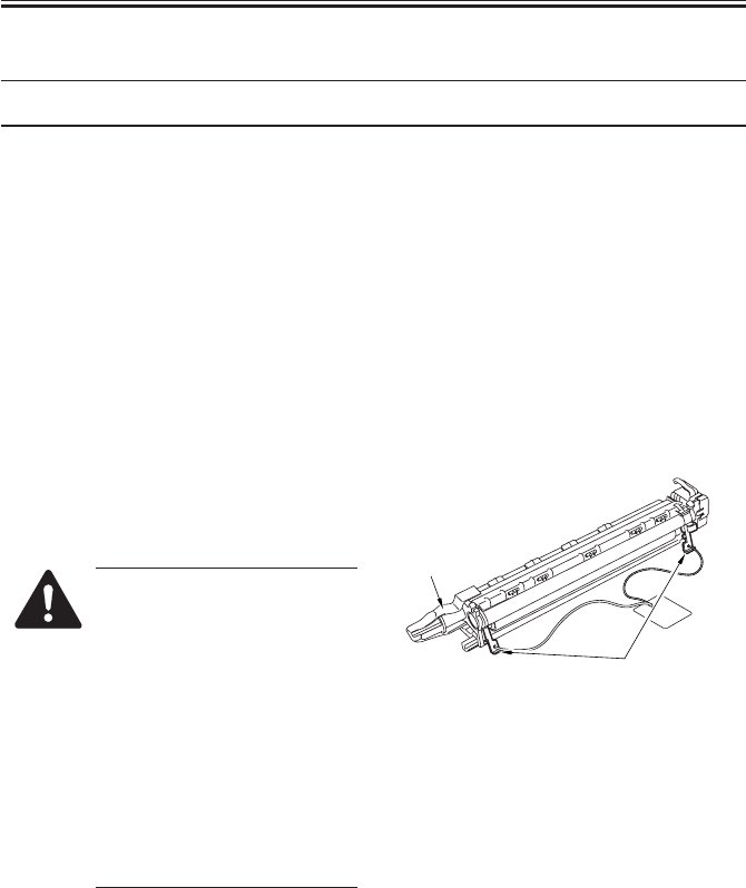
COPYRIGHT
©
2001 CANON INC. 2000 2000 2000 2000 CANON iR2200/iR2800/iR3300 REV.0 MAR. 2001
CHAPTER 3 INSTALLATION
3-27 S
6 Replacing the Drum Unit
Work Checks/remarks
1) Turn off the main power switch; then,
open the front cover.
2) Shift the feeding assembly releasing le-
ver to free the feeding assembly.
3) Turn the developing assembly locking
lever counterclockwise to free the de-
veloping assembly.
4) Remove the fixing screw from the drum
unit.
(The removed fixing screw will be used
when mounting the new drum unit.)
5) Pull the drum unit straight out to the
front.
6) Unpack the new drum unit, and detach
the two releasing members of the pri-
mary charging roller.
1. Do not touch the drum area to
avoid scratching the photo-
sensitive drum.
2. Do not expose the photosen-
sitive drum to strong light.
3. Take care not to damage the
stirs found on the bottom of
the drum unit.
4. When removing the tape from
the rear end of the drum unit,
keep the rear end higher than
the front cover to prevent
spilling waste toner.
Primary charging roller
releasing members
Tape
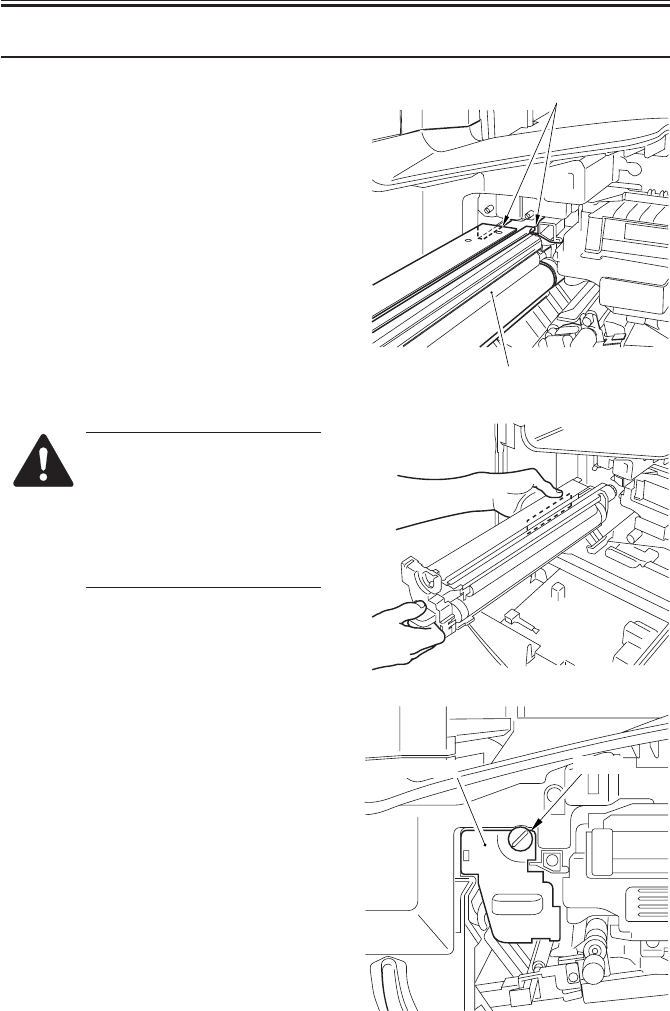
COPYRIGHT
©
2001 CANON INC. 2000 2000 2000 2000 CANON iR2200/iR2800/iR3300 REV.0 MAR. 2001
CHAPTER 3 INSTALLATION
3-28 S
Work Checks/remarks
7) Check to see the developing assembly is
freed; then, slide in the new drum unit
along the rails in the machine slowly. At
this time, take full care not to bring the
developing assembly into contact with
the developing cylinder, which is lo-
cated very close.
To avoid damaging the stirs
found on the bottom of the
drum unit, hold the front cover
of the drum unit with your right
hand while keeping your left
hand in the long hole of the left
side plate of the drum unit.
8) Secure the new drum unit in place using
the fixing screw you removed in a pre-
vious step.
Rails
Drum unit
Drum unit Screw
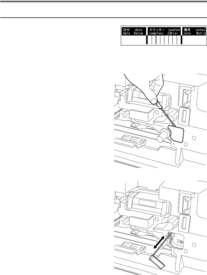
COPYRIGHT
©
2001 CANON INC. 2000 2000 2000 2000 CANON iR2200/iR2800/iR3300 REV.0 MAR. 2001
CHAPTER 3 INSTALLATION
3-29 S
Work Checks/remarks
9) Fill out the date label, and attach it to
the front cover of the drum unit.
10) Turn the developing assembly locking
lever clockwise to lock it in place.
11) Shift up the feeding assembly releasing
lever to set the feeding assembly in
place.
12) Remove the paper lint cleaning cover
using a flat-blade screwdriver.
13) Slide out the paper lint cleaning lever,
and move it back and forth.
14) Mount the paper lint cleaning cover.
15) Close the front cover.
16) Turn on the main power switch.

COPYRIGHT
©
2001 CANON INC. 2000 2000 2000 2000 CANON iR2200/iR2800/iR3300 REV.0 MAR. 2001
CHAPTER 3 INSTALLATION
3-30 S
Work Checks/remarks
17) Start service move.
18) Make the following selections:
COPIER>FUNCTION>DPC>D-
GAMMA.
19) Press the OK key.
• The machine will pick up paper from
cassette 2. (The paper may be of any
size.)
• The machine ends APVC correction by
delivering a blank sheet.
20) Press the Reset key twice to end service
mode.
21) Turn off the main power switch.
Press ; '2' and '8' at the same time,
and then once again.

COPYRIGHT
©
2001 CANON INC. 2000 2000 2000 2000 CANON iR2200/iR2800/iR3300 REV.0 MAR. 2001
READER UNIT

COPYRIGHT
©
2001 CANON INC. 2000 2000 2000 2000 CANON iR2200/iR2800/iR3300 REV.0 MAR. 2001
CONTENTS
R1
Contents
CHAPTER 1 BASIC OPERATION
CHAPTER 2 ORIGINAL EXPOSURE SYSTEM
1 Outline of Electrical Circuitry....... 1-1R
1.1 Outline .................................... 1-1R
1.2 Reader Controller PCB ........... 1-1R
2 Basic Sequence of Operations....... 1-2R
2.1 Basic Sequence of Operations at
Power-On ................................ 1-2R
1 Outline of Operations .................... 2-1R
1.1 Outline .................................... 2-1R
1.2 Sequence of Operations (original
exposure) ................................. 2-3R
1.2.1 Book Mode, 1 Original,
Copyboard Closed ............ 2-3R
1.2.2 Book Mode, 1 Original,
Copyboard Cover Open .... 2-4R
1.3 Enlargement/Reduction (zoom)
................................................ 2-5R
1.3.1 Changing the Reproduction Ra-
tio in Main Scanning Direction
.......................................... 2-5R
1.3.2 Changing the Reproduction Ra-
tio in Sub Scanning Direction
.......................................... 2-5R
2 Scanner Drive System ................... 2-6R
2.1 Outline .................................... 2-6R
2.2 Controlling the Scanner Motor
................................................ 2-7R
2.2.1 Controlling the Motor When
Scanning an Image ........... 2-7R
2.2.2 Reversing the Scanner After
Scanning in Main Reading Di-
rection ............................... 2-8R
3 Controlling the Scanning Lamp (LA2)
....................................................... 2-9R
3.1 Outline .................................... 2-9R
3.2 Scanning Lamp ....................... 2-9R
2.2 Basic Sequence of Operations in
Book Mode ............................. 1-2R
3 Inputs to and Outputs from the Major
PCBs.............................................. 1-3R
3.1 Wiring of Major PCBs ............ 1-3R
3.3 Turning On/Off the Lamp ....... 2-9R
3.4 Detecting an Error................. 2-10R
4 Detecting the Size of Originals ... 2-11R
4.1 Outline .................................. 2-11R
4.2 Points of Detection ............... 2-11R
4.3 Outline of Detection ............. 2-11R
4.4 Outline of Detection Operation
.............................................. 2-12R
4.4.1 Book Mode, 1 Original,
Copyboard Cover Open ... 2-12R
4.4.2 Book Mode, 1 Original,
Copyboard Cover Close ... 2-13R
5 Disassembly and Assembly ......... 2-15R
5.1 Exposure Lamp ..................... 2-16R
5.1.1 Removing the Exposure Lamp
........................................ 2-16R
5.1.2 After Replacing the Scanning
Lamp ............................... 2-17R
5.2 Scanner Drive Assembly ....... 2-18R
5.2.1 Removing the Scanner Motor
........................................ 2-18R
5.2.2 Mounting the Motor Unit
........................................ 2-19R
5.2.3 Removing the Scanner Drive
Cable ............................... 2-20R
5.2.4 Routing the Scanner Drive
Cable ............................... 2-21R
5.2.5 Adjusting the Position of the No.
1/No. 2 Mirror Base ........ 2-22R

COPYRIGHT
©
2001 CANON INC. 2000 2000 2000 2000 CANON iR2200/iR2800/iR3300 REV.0 MAR. 2001
CONTENTS
R2
CHAPTER 3 IMAGE PROCESSING SYSTEM
5.3 Sensors .................................. 2-24R
5.3.1 Removing the Original Detec-
tion Unit .......................... 2-24R
5.3.2 Removing the HP Sensor
........................................ 2-24R
5.3.3 Removing the Original Cover
Sensor ............................. 2-25R
5.4 PCBs ..................................... 2-26R
5.4.1 Removing the Inverter PCB
........................................ 2-26R
1 Outline ........................................... 3-1R
2 Analog Image Processing.............. 3-2R
2.1 Outline .................................... 3-2R
2.2 Driving the CCD ..................... 3-2R
2.3 Gain Correction and Offset Correc-
tion of the CCD Output .......... 3-3R
2.4 A/D Conversion of the CCD Output
................................................ 3-3R
3 Digital Image Processing .............. 3-4R
3.1 Outline .................................... 3-5R
3.2 Shading Correction ................. 3-5R
3.2.1 Outline .............................. 3-5R
3.2.2 Shading Adjustment ......... 3-6R
3.2.3 Shading Correction ........... 3-6R
3.2.4 Edge Gain Correction (ADF in
use) ................................... 3-6R
3.3 Auto Density Adjustment (AE)
................................................ 3-7R
3.3.1 Outline .............................. 3-7R
3.3.2 ABC Circuit ...................... 3-7R
3.4 Related Service Mode ............. 3-8R
4 Disassembly and Assembly ........... 3-9R
4.1 External Covers..................... 3-10R
4.1.1 External Covers .............. 3-10R
4.1.2 Removing the Reader Right
Cover .............................. 3-10R
4.1.3 Removing the Copyboard Glass
........................................ 3-11R
4.1.4 After Mounting the Copyboard
Glass ............................... 3-11R
4.2 CCDs ..................................... 3-12R
4.2.1 Removing the CCD Unit 3-12R
4.2.2 Points to Note When Replacing
the CCD Unit .................. 3-13R
4.3 Frames ................................... 3-14R
4.3.1 Removing the Left ADF Base
Unit ................................. 3-14R
4.3.2 Removing the Reader Upper
Frame .............................. 3-14R
4.3.3 Mounting the Reader Upper
Frame .............................. 3-15R
4.4 PCBs ..................................... 3-16R
4.4.1 Removing the Reader Control-
ler PCB ........................... 3-16R
4.4.2 When Replacing the Reader
Controller PCB ............... 3-16R

COPYRIGHT
©
2001 CANON INC. 2000 2000 2000 2000 CANON iR2200/iR2800/iR3300 REV.0 MAR. 2001
CHAPTER 1
BASIC OPERATION
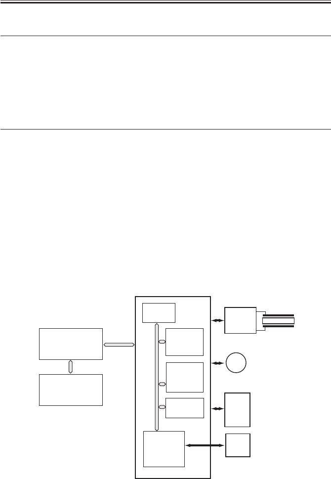
COPYRIGHT
©
2001 CANON INC. 2000 2000 2000 2000 CANON iR2200/iR2800/iR3300 REV.0 MAR. 2001
CHAPTER 1 BASIC OPERATION
1-1 R
CCD
PCB
ADF
Scanner
motor
Reader controller PCB
Controller unit
Printer unit
Inverter
PCB LAMP1
M400
ROM
(IC401)
CPU
(IC400)
RAM
(IC402)
IPC
(IC404)
EEPROM
(IC403)
F01-102-01 Major PCBs
T01-102-01 List of Control Items
1 Outline of Electrical Circuitry
1.1 Outline
The major mechanisms of the reader unit are controlled by the CPU on the reader control-
ler PCB.
The functions of the major ICs are as indicated in the following table.
1.2 Reader Controller PCB
Name
CPU
RAM
EEP-ROM
ROM
Description
• Controls the sequence of scanner
operations.
• Controls the original size detection
mechanism.
• Controls the CCD.
• Controls the communications with
the ADF.
• Stores service mode data.
• Stores user mode data.
• Stores control data.
• Backs up RAM data.
• Stores control programs.
• Controls the scanning lamp.
• Controls shading correction.
• Controls service mode.
• Controls the communications with
the main controller.
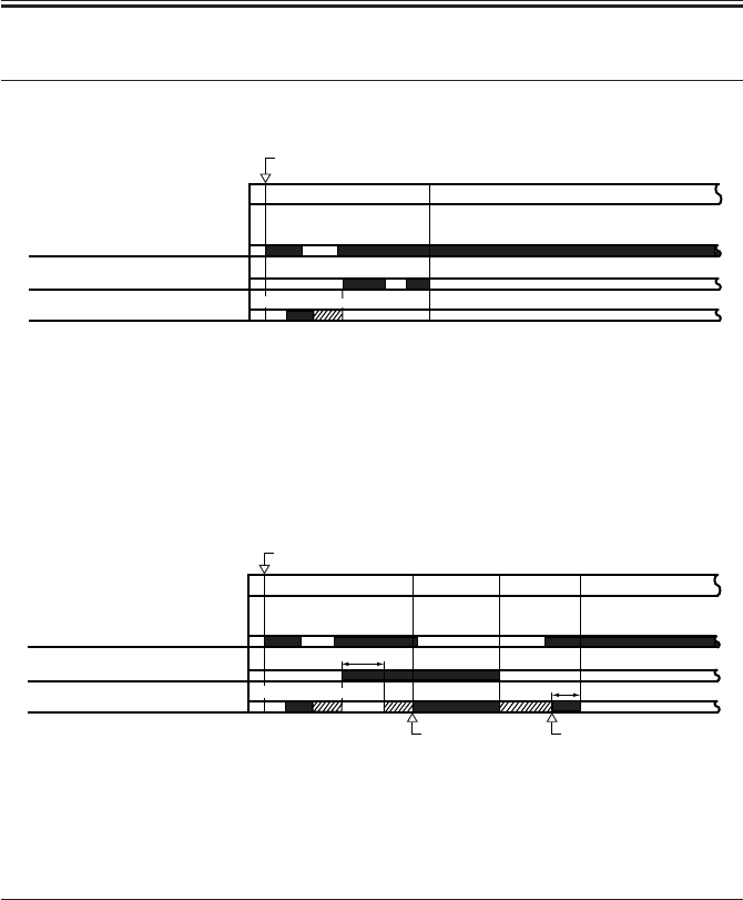
COPYRIGHT
©
2001 CANON INC. 2000 2000 2000 2000 CANON iR2200/iR2800/iR3300 REV.0 MAR. 2001
CHAPTER 1 BASIC OPERATION
1-2 R
2 Basic Sequence of Operations
2.1 Basic Sequence of Operations at Power-On
Scanner HP sensor (PS39)
Scanning lamp (LA2)
Scanner motor (M3)
Power switch ON
STBY
SREADY
*1 *2
Reverse
Forward
Scanner HP sensor (PS39)
Scanning lamp (LA2)
Scanner motor (M3)
STBYSREADY SCFW SCRV
Start key ON
Start position Start position
*1
*2
ReverseForward
*1: Shading adjustment (gain adjustment) is executed 1 sec after the scanning lamp turns
on.
*2: Shading adjustment (CCD original size detection slash level adjustment) is executed 1
sec after the scanning lamp turns on.
F01-201-01
2.2 Basic Sequence of Operations in Book Mode
T01-202-01
*1: Shading correction (gain adjustment and CCD original size detection slash level adjust-
ment) is executed for every job.
*2: Executed only at the end of a scan job.
F01-202-02
Name of period
SREADY(scanner ready)
SCFW(scanner forward)
SCRV(scanner reverse)
STBY(standby)
Description
From when the power switch is turned on to when shading ad-
justment ends.
Or, from when the Start key is turned on to when the scanner
reaches scanner start position.
While the scanner is moving forward to scan the original.
While the scanner is moving in reverse.
From when shading correction ends to when the Start key is
turned on or when the power switch is turned off.
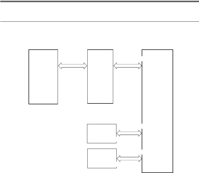
COPYRIGHT
©
2001 CANON INC. 2000 2000 2000 2000 CANON iR2200/iR2800/iR3300 REV.0 MAR. 2001
CHAPTER 1 BASIC OPERATION
1-3 R
3 Inputs to and Outputs from the Major PCBs
3.1 Wiring of Major PCBs
F01-301-01
Controller
unit
DC
controller
PCB
CCD PCB
Inverter PCB
Reader
controller
PCB
J4021
J402
J408/J407/J403
J409
J601/J600/J602

COPYRIGHT
©
2001 CANON INC. 2000 2000 2000 2000 CANON iR2200/iR2800/iR3300 REV.0 MAR. 2001
CHAPTER 2
ORIGINAL EXPOSURE SYSTEM

COPYRIGHT
©
2001 CANON INC. 2000 2000 2000 2000 CANON iR2200/iR2800/iR3300 REV.0 MAR. 2001
CHAPTER 2 ORIGINAL EXPOSURE SYSTEM
2-1 R
Item
Scanning lamp
Original Scanning
Scanner position detection
Reproduction ratio (zoom)
Scanner drive control
Lens
Scanning lamp activation
Original size detection
1 Outline of Operations
1.1 Outline
The major functions of the original exposure system are as follows:
Description
Xenon lamp
In book mode: by moving the scanner.
With ADF in use: by stream reading while holding the No. 1
mirror base fixed in position.
By scanner HP sensor (PS400)
[1] Using the Copyboard: 25% to 800%
• In main scanning direction, image processing is per-
formed by the controller unit.
• In sub scanning direction, the speed of the No. 1 mirror
base is changed (50% or higher and lower than 400%),
in addition, the image data is processed by the control-
ler unit (lower than 50% and 400% or higher).
[2] Using the ADF: 25% to 200%
• In main scanning direction, the image data is processed
by the controller unit.
• In sub scanning direction, the speed at which the origi-
nals are moved is changed (50% or higher and lower
than 200%), in addition, the image data is processed by
the controller unit (lower than 50%and 200% or
higher).
The No.1/No.2 mirror base is controlled by means of a step-
ping motor (M400).
Lens array (fixed in position)
[1] Turned on by an inverter circuit.
[2] Monitored for errors.
[1] In book mode, by a reflection type sensor in sub scan-
ning direction; by a CCD in main scanning direction.
[2] With the ADF in use, by the ADF.
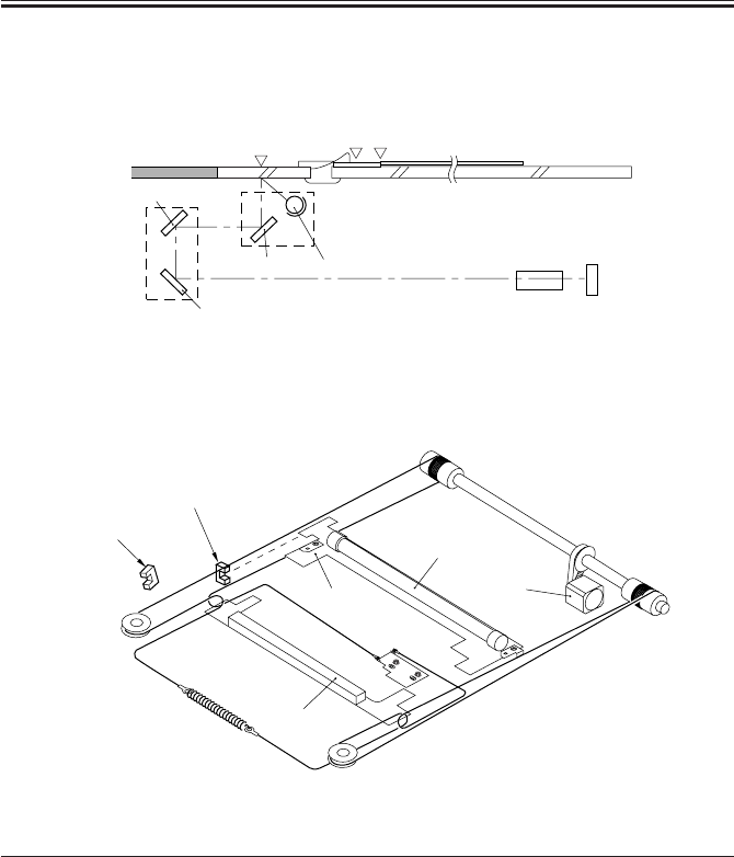
COPYRIGHT
©
2001 CANON INC. 2000 2000 2000 2000 CANON iR2200/iR2800/iR3300 REV.0 MAR. 2001
CHAPTER 2 ORIGINAL EXPOSURE SYSTEM
2-2 R
Copyboard glass
Original
Scanning lamp Lens CCD
No. 1 mirror
No. 1 mirror base
No. 2 mirror
No. 2 mirror
base No. 3 mirror
HP
Image leading
edge
Stream reading position
(start position)
F02-101-01
The major components of the original exposure system are as follows:
Component
[1] Scanning lamp
[2] Scanner motor
[3] Scanner HP sensor
[4] Copyboard cover
sensor
[5] No.1 mirror base
[6] No.2 mirror base
Notation
LAMP1
M400
PS400
PS401
-
Description
Xenon lamp (intensity of 40,000 lx)
2-phase stepping motor (under pulse control)
Photointerrupter (detects scanner home position)
Photointerrupter (detects the state (open/closed) of
copyboard cover)
No. 1 mirror
No. 2/No. 3 mirror
F02-101-02
[6]
[4]
[5]
[1]
[2]
[3]

COPYRIGHT
©
2001 CANON INC. 2000 2000 2000 2000 CANON iR2200/iR2800/iR3300 REV.0 MAR. 2001
CHAPTER 2 ORIGINAL EXPOSURE SYSTEM
2-3 R
1.2 Sequence of Operations (original exposure)
1.2.1 Book Mode, 1 Original, Copyboard Closed
*1: original size detection.*2: shading correction.
F02-102-01
F02-102-02
Forward
*2
*1
Start key ON
Copyboard cover opens
Copyboard cover closes
Scanner HP sensor
(PS400)
Copyboard cover
sensor (PS401)
Scanning lamp
(LAMP1)
Scanner motor
(M400)
STBY
STBY
SREADY
SCFW SCRV
Start position
HP
Start position
Point of original
size detection
Reverse
HP Image leading
edge Image
end Stop
position
Stream reading
position (start position) Point of original
size detection
1. The copyboard cover is opened.
The scanner moves to the point of original
size detection.
2. The copyboard cover is closed.
When the original size has been detected,
the scanner moves to home position.
3. The Start key is pressed.
After shading correction, the scanner
moves to start position.
4. The scanner scans the original.
5. The scanner returns to start position
(at the speed used for 50% reduction).
6. The scanner moves to home position and
remains in wait.
: No. 1 mirror position.
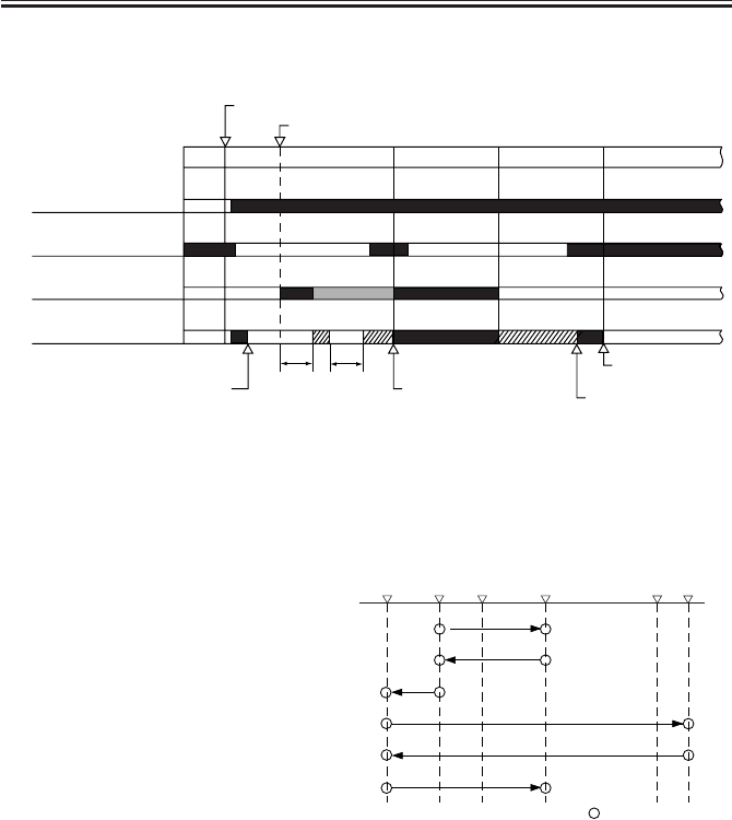
COPYRIGHT
©
2001 CANON INC. 2000 2000 2000 2000 CANON iR2200/iR2800/iR3300 REV.0 MAR. 2001
CHAPTER 2 ORIGINAL EXPOSURE SYSTEM
2-4 R
1.2.2 Book Mode, 1 Original, Copyboard Cover Open
*1: original size detection.*2: shading correction.
F02-102-03
F02-102-04
Reverse
Forward
*2
STBY
STBY
SREADY SCFW SCRV
Start key ON
Copyboard cover open
Start position
Start position
Point of original size detection
*1 Point of original
size detection
Scanner HP sensor
(PS400)
Copyboard cover
sensor (PS401)
Scanning lamp
(LAMP1)
Scanner motor
(M400)
1. The copyboard cover is opened.
The scanner moves to the point of original detection.
2. The Start key is pressed. After the original size has
been detected, the scanner moves to home position.
3. After shading correction in home position,
the scanner moves to start position.
4. The scanner scans the original.
5. The scanner returns to start position
(at the speed used for 50% reduction).
6. The scanner moves to the point of original size
detection.
HP
Image
leading
edge Image
end Stop
position
Stream reading
position
(start position) Point of original
size detection
: No. 1 mirror base
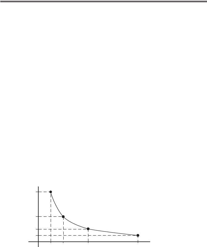
COPYRIGHT
©
2001 CANON INC. 2000 2000 2000 2000 CANON iR2200/iR2800/iR3300 REV.0 MAR. 2001
CHAPTER 2 ORIGINAL EXPOSURE SYSTEM
2-5 R
1.3 Enlargement/Reduction (zoom)
[1] When the copyboard cover is used, the ratio may be between 25% and 800% and the
speed of the scanner is controlled.
[2] When the ADF is used, the ratio may be between 25% and 400% and the speed of
moving the originals is controlled.
1.3.1 Changing the Reproduction Ratio in Main Scanning Direction
For main scanning direction, the original is read at 100% (for both copyboard and ADF);
the size is changed by processing data in the main controller unit.
[1] To reduce, data units are skipped when writing image data to the line memory.
[2] To enlarge, data units are read multiple times when reading image data from the line
memory.
1.3.2 Changing the Reproduction Ratio in Sub Scanning Direction
For sub scanning direction, the speed of the scanner/movement of the original is changed.
However, for a reduction between 25% and 49% and enlargement between 401% and 800%,
data processing in the main controller assembly is also used in combination.
[1] For enlargement, the speed of the mirror/original is reduced from that used in Direct:
e.g., at 200%, the speed is 1/2 of the speed used in Direct.
[2] For reduction between 50% and 99%, the speed of the mirror/original is increased;
e.g., at 50%, the speed is twice as high as that used in Direct.
F02-103-01
[3] To reduce to between 25% and 49%, the image data read at 50% and 98% is subjected
to skipping (1/2) in the main controller unit.
[4] For an enlargement between 401% and 800%, image data read at 200% to 400% is
sub-jected to repeating (doubling) in the main controller assembly.
400%200%100%
50%
2
1
1/2
1/4
(speed ratio)
(image ratio)
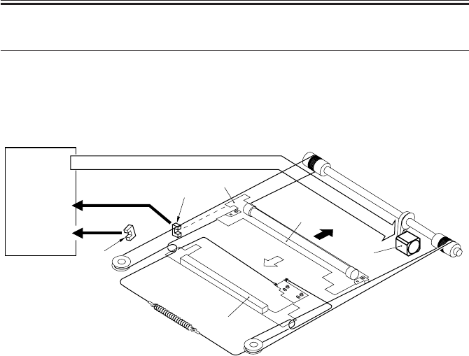
COPYRIGHT
©
2001 CANON INC. 2000 2000 2000 2000 CANON iR2200/iR2800/iR3300 REV.0 MAR. 2001
CHAPTER 2 ORIGINAL EXPOSURE SYSTEM
2-6 R
2 Scanner Drive System
2.1 Outline
The following parts are associated with the scanner drive system.
F02-201-01
[1] Scanner Motor (M3) Control Signal
Used to turn on/off the motor and to control its direction and speed of rotation.
[2] Scanner HP Sensor (PS39) Detection Signal
Used to make sure that the No. 1 mirror base is at home position.
[3] Copyboard Cover Sensor (PS40) Detection Signal
Used to detect the state (open or close) of the copyboard cover.
[4] Reader controller PCB
[5] No.1 mirror base
[6] Scanner motor
[7] Scanner HP sensor
[8] Copyboard cover sensor
[9] Light-blocking plate
[10] No.2 mirror base
[10]
[8]
[9]
[5]
[6]
[7]
[1]
[4] [2]
[3]

COPYRIGHT
©
2001 CANON INC. 2000 2000 2000 2000 CANON iR2200/iR2800/iR3300 REV.0 MAR. 2001
CHAPTER 2 ORIGINAL EXPOSURE SYSTEM
2-7 R
2.2 Controlling the Scanner Motor
The system used to control the scanner motor is constructed as follows:
The motor driver turns on/off the scanner motor and controls its direction and speed of
rotation in keeping with the signals from the CPU and motor driver controller.
F02-202-01
2.2.1 Controlling the Motor When Scanning an Image
When scanning an image, the motor is controlled as follows, thereby controlling the
movement of the No. 1 mirror base unit:
[1] Acceleration. Used to accelerate until the speed most appropriate to the read ratio is
attained.
[2] Approach run. Used to ensure that speed stabilizes.
[3] Image read. Used to read the image at a specific speed suited to the read ratio.
[4] Deceleration. Used to enable the scanner to speed down and stop promptly, starting at
the end of the image.
F02-202-02
HP Image leading edge Image end
Stream reading position
(start position) Stop
Accelerate Maintain
Travel
speed
Travel distance
[1] [2] [3] [4]
Decelerate
Motor driver
contoroller
Scanner motor
Reader controller PCB J401
M400
1
5
2
3
6
4
A
A*
B
B*
+24V
Motor
driver
CPU
COPYRIGHT
©
2001 CANON INC. 2000 2000 2000 2000 CANON iR2200/iR2800/iR3300 REV.0 MAR. 2001
CHAPTER 2 ORIGINAL EXPOSURE SYSTEM
2-8 R
Vertical size plate
Standard white plate
Increase
Decrease
Copyboard glass
Vertical size plate
Standard white plate
Increase Decrease
Copyboard glass
Shading
position
F02-202-04
2.2.2 Reversing the Scanner After Scanning in Main Reading Direction
When the image has been scanned, the No. 1 mirror base is moved in reverse to home po-
sition at the speed used for 50% reduction, regardless of the ratio being used.
E202 (HP detection error)
[1] The No. 1 mirror base does not reach the HP sensor within a specific
period of time.
[2] The HP sensor identifies the presence of the No. 1 mirror base when the
No. 1 mirror base should have been moved away.
E204 (image leading edge detection error)
[1] The ADF does not generate the image leading edge signal in stream
reading mode.
COPIER>ADJUST>ADJ-XY>ADJ-X (scanner image leading edge
adjustment)
Enter an appropriate value to adjust the image leading edge position.
Range: 250 through 290 (a change of ‘1’ causes a shift of 0.1 mm)
COPIER>FUNCTION>CCD>SHDG-POS (shading position adjust-
ment)
• Execute this mode if a white line still appears after executing
COPIER>FUNCTION>CCD>SH-PS-ST or after cleaning the scanner
mechanisms.
• After entering a setting and executing
COPIER>FUNCTION>CCD>SH-PS-ST, check to make sure that ‘OK’ is
indicted. Thereafter, make a test print to be user that no white line is found
in its halftone area.
Range: 240 to 320 (a multiple of 8 causes a shift of about 0.17 mm)
F02-202-03
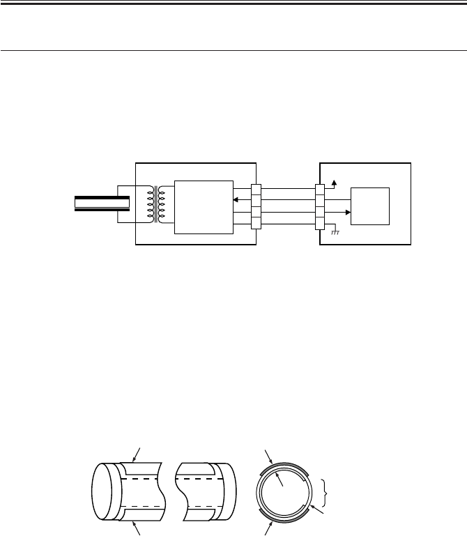
COPYRIGHT
©
2001 CANON INC. 2000 2000 2000 2000 CANON iR2200/iR2800/iR3300 REV.0 MAR. 2001
CHAPTER 2 ORIGINAL EXPOSURE SYSTEM
2-9 R
3 Controlling the Scanning Lamp (LA2)
3.1 Outline
The system used to control the scanning lamp is constructed as follows and the items of
control include the following:
[1] Turning on and off the scanning lamp.
[2] Monitoring the scanning lamp for errors.
F02-301-01
3.2 Scanning Lamp
The machine’s scanning lamp is a xenon lamp of a non-electrode discharge type, in which
xenon gas is sealed in a tube.
On the outside of the glass tube, two electrodes are arranged parallel to the tube axis, and
the inner side of the glass tube is coated with fluorescent material.
The internal gas discharges and, as a result, the fluorescent material glows when a high-
frequency voltage is applied across the electrodes.
F02-302-01
3.3 Turning On/Off the Lamp
The scanning lamp is turned on/off in response to the drive signal (LAMP_ON) from the
CPU on the reader controller PCB. When the signal is generated, the inverter generates a
high-frequency voltage using the drive voltage (+24 V) supplied by the reader controller
PCB to turn on the xenon tube.
Inverter PCB
Xenon lamp Activation
control
circuit
J4021 J402 +24V
Reader controller
PCB
1
3
4
2
5
3
2
4
LAMP_ON
INV_ERR
LAMP1 CPU
Fluorescent
material
Electrode
Opening
Electrode
ElectrodeElectrode
Glass tube

COPYRIGHT
©
2001 CANON INC. 2000 2000 2000 2000 CANON iR2200/iR2800/iR3300 REV.0 MAR. 2001
CHAPTER 2 ORIGINAL EXPOSURE SYSTEM
2-10 R
3.4 Detecting an Error
The reader controller circuit generates the error signal (INV_ERR) in response to an error
(e.g., output open, short circuit, leak) in the inverter circuit. A fault in the lamp (low inten-
sity, activation failure) will be identified as an activation error caused by lack of intensity
during initial activation (e.g., at time of shading correction).
E220
It is used to indicate a fault in the inverter PCB.
E225
It is used to indicate a fault in the scanning lamp (xenon tube).
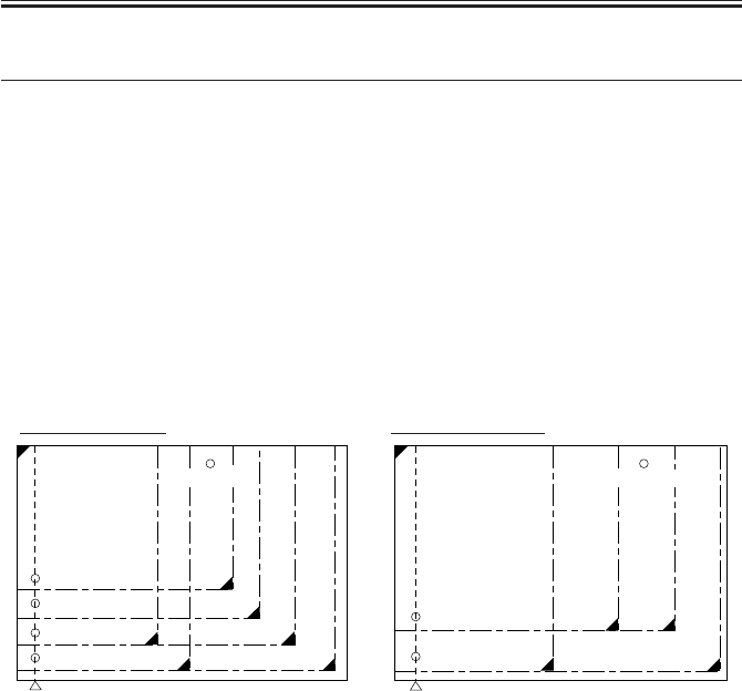
COPYRIGHT
©
2001 CANON INC. 2000 2000 2000 2000 CANON iR2200/iR2800/iR3300 REV.0 MAR. 2001
CHAPTER 2 ORIGINAL EXPOSURE SYSTEM
2-11 R
4 Detecting the Size of Originals
4.1 Outline
The machine automatically identifies the size of originals based on the combination of in-
tensities measured by reflection type sensors and CCD at specific points.
• For main scanning direction, the CCD is used to take measurements (if AB, 4 points; if
Inch, 2 points).
• For sub scanning direction, a reflection type photosensor is used (1 point).
4.2 Points of Detection
For main scanning direction, the No. 1 mirror base is moved to the following points in re-
lation to the position of the original to measure the intensity at each point.
For sub scanning direction, on the other hand, measurements are taken while holding the
sensor in place at a specific point.
F02-402-01
4.3 Outline of Detection
The machine identifies the size of originals in the following two steps:
[1] Detecting External Light (main scanning direction only)
While keeping the scanning lamp off, the CCD level at each point of detection in main
scanning direction is measured. A point at which external light is detected will be iden-
tified as indicating the absence of an original, enabling the identification of the width
of an original.
[2] Detecting the Sensor Output Level
The scanning lamp is turned on, and the CCD level at each point of detection in main
scanning direction is measured. In addition, the reflection type photosensor in sub
scanning direction is turned on to measure the sensor output.
The combination of these output measurements is used to identify the size of the origi-
nal. For specific movements, see the pages that follow.
AB-Configuration Inch-Configuration
Point of original
detection 3
Point of original
detection 4
Point of original
detection 1
Point of original
detection 2
B5
A4
B5R
A4R
B4
A3
Point of CCD original detection Point of CCD original detection
Point of original
detection 1
Point of original
detection 2
LTRR
LTR
LGL
279.4×431.8mm
(11"×17")
Original sensor Original sensor
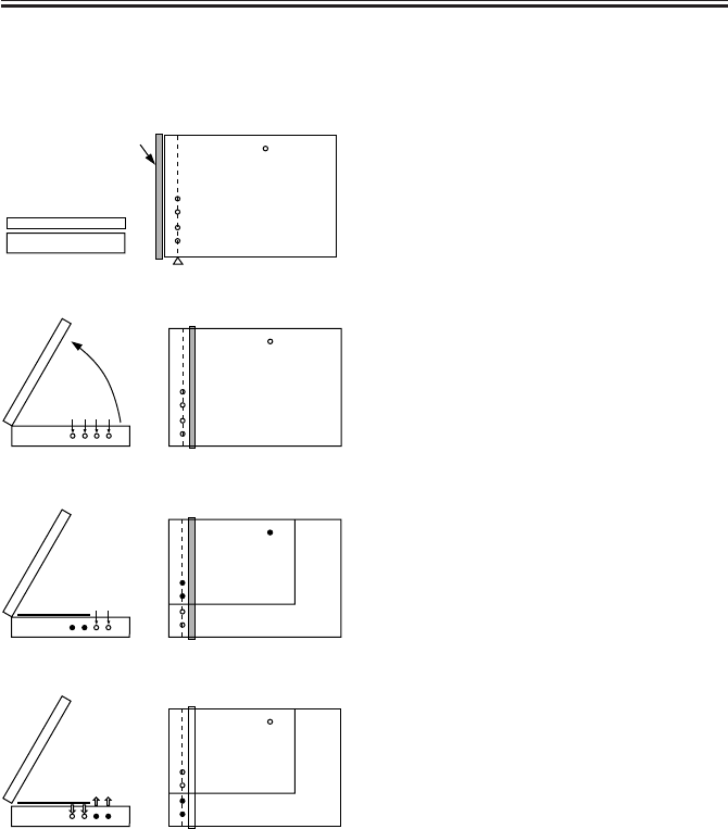
COPYRIGHT
©
2001 CANON INC. 2000 2000 2000 2000 CANON iR2200/iR2800/iR3300 REV.0 MAR. 2001
CHAPTER 2 ORIGINAL EXPOSURE SYSTEM
2-12 R
F02-404-01
Point of original detection
Copyboard glass
Xenon lamp
Original sensor
Reader unit
Copyboard cover Point of original detection 1
Point of original detection 2
Point of original detection 3
Point of original detection 4
(external light)
Original (A4R)
(external light)
4.4 Outline of Detection Operation
4.4.1 Book Mode, 1 Original, Copyboard Cover Open
[1] The scanner remains in wait.
No. 1 mirror base: at HP
Xenon lamp: off
Original sensor: disabled
[2] The copyboard is opened.
Detection starts of external light in main
scanning direction.
No. 1 mirror base: to point of original de-
tection
Xenon lamp: off
Original sensor: disabled
[3] An original is placed.
The width of the original is identified in
relation to the presence/absence of external
light; here, the absence of an original is
identified at points in question, eliminating
B5, B4, A4, and A3.
[4] The Start key is pressed.
In response, original detection is started.
For main scanning direction, the xenon
lamp is turned on to check for reflected
light by the CCD (4 points).
For sub scanning direction, the original
sensor starts detection.
The absence of external light is identified
as indicating the absence of an original.
The machine will identify the size of an
original based on the combination of the
results (T02-404-01)
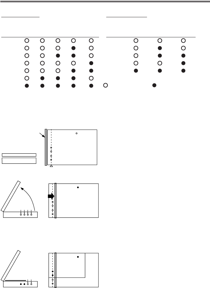
COPYRIGHT
©
2001 CANON INC. 2000 2000 2000 2000 CANON iR2200/iR2800/iR3300 REV.0 MAR. 2001
CHAPTER 2 ORIGINAL EXPOSURE SYSTEM
2-13 R
Originals
size
A3
B4
A4R
A4
B5
B5R
None
Original
sensor
Point of CCD detection
1234
AB-Configuration
Originals
size
11"×17"
LGL
LTRR
LTR
None
Originals
sensor
Point of CCD detection
12
Inch-Configuration
: reflection present : reflection absent
[1] The scanner remains in wait.
No. 1 mirror base: HP
Xenon lamp: off
Original sensor: disabled
[2] The copyboard cover is opened.
Detection starts of external light in main
scanning direction.
No. 1 mirror base: to point of original de-
tection
Xenon lamp: off
Original sensor: disabled
[3] An original is set.
The width of an original is identified in
terms of the presence or absence of exter-
nal light; here, the external light is blocked
and the absence of an original is identified,
excluding B5, B4, A4, and A3.
Point of original detection
Point of original detection 1
Point of original detection 2
Point of original detection 3
Point of original detection 4
Copyboard glass
Xenon lamp Original sensor
Reader unit
Copyboard cover
(external light)
(external light)
Original (A4R)
T02-404-01
4.4.2 Book Mode, 1 Original, Copyboard Cover Close
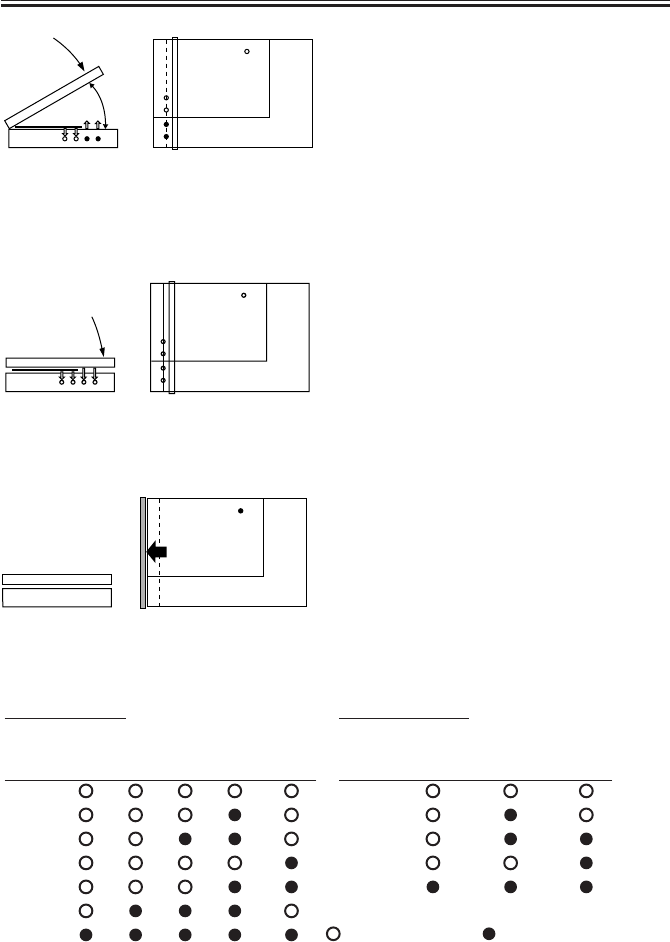
COPYRIGHT
©
2001 CANON INC. 2000 2000 2000 2000 CANON iR2200/iR2800/iR3300 REV.0 MAR. 2001
CHAPTER 2 ORIGINAL EXPOSURE SYSTEM
2-14 R
Originals
size
A3
B4
A4R
A4
B5
B5R
None
Original
sensor
Point of CCD detection
1234
AB-Configuration
Originals
size
11"* 17"
LGL
LTRR
LTR
None
Original
sensor
Point of CCD detection
12
Inch-Configuration
: Changes : Does not changes
T02-404-02
[4] The copyboard cover is closed.
When the copyboard cover is brought
down to 25°, the Copyboard cover sensor
detects the “closed” state, and original size
detection starts.
For main scanning direction, the xenon
lamp is turned on, and the CCD checks for
reflected light (4 points).
For sub scanning direction, the original
sensor starts detection.
[5] The copyboard cover is fully closed.
The changes in the output level of each
sensor are monitored until the copyboard
cover is fully closed. The absence of a
change is identified as indicating the ab-
sence of paper, and the size of the original
is identified based on the combination of
changes in level at five points (T02-404-
02).
[6] The scanner remains in wait (for a press on
the Start key).
The No. 1 mirror base moves to home posi-
tion, and the scanner waits for a press on
the Start key (wait state).
25˚
F02-404-02

COPYRIGHT
©
2001 CANON INC. 2000 2000 2000 2000 CANON iR2200/iR2800/iR3300 REV.0 MAR. 2001
CHAPTER 2 ORIGINAL EXPOSURE SYSTEM
2-15 R
5 Disassembly and Assembly
The discussions that follow cover the machine’s mechanical characteristics and how to
disassemble/assemble the machine. Keep the following in mind whenever you work with the
machine:
1. The power plug must remain disconnected for safety when disassembling/assembling
the machine.
2. Unless otherwise noted, the machine may be assembled by reversing the steps used to
disassemble it.
3. The screws must be identified by type (length, diameter) and location.
4. The mounting screws used for the grounding wire and the varistors come with a washer,
which must not be left out when assembling the machine.
5. As a rule, the machine must not be operated with any of its parts removed.
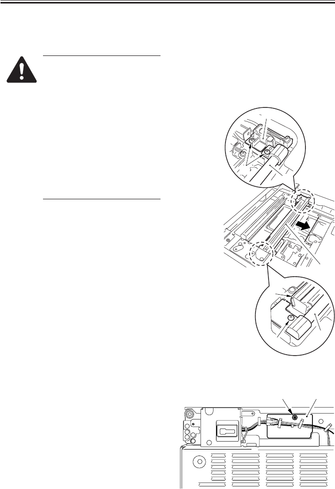
COPYRIGHT
©
2001 CANON INC. 2000 2000 2000 2000 CANON iR2200/iR2800/iR3300 REV.0 MAR. 2001
CHAPTER 2 ORIGINAL EXPOSURE SYSTEM
2-16 R
5.1 Exposure Lamp
5.1.1 Removing the Exposure Lamp
• Do not start to work if the
lamp is hot.
• Do not leave fingerprints on
the surface of the lamp.
• Do not subject the lamp to
impact.
• Do not touch the light win-
dow of the lamp without a
means of protection.
• Do not impose force on the
lamp.
• If the surface of the lamp is
soiled, dry wipe it.
1) Remove the copyboard glass. (p. 3-11R)
2) Remove the reader front cover (2
screws) and the reader rear cover (5
screws).
3) While taking care not to hold the scan-
ning lamp [1] and the reflecting shade
[2], move the No. 1 mirror base [3] as
far as the cut-off in the frame.
4) Remove the three screws [4] from the
No. 1 mirror base, and detach the scan-
ning lamp [1] together with the cable
fixing plate [5].
F02-501-01
5) Remove the screw [1], and detach the
connector cover [2] found at the rear.
F02-501-02
[1]
[4]
[2]
[4] [1]
[5]
[3]
[1] [2]
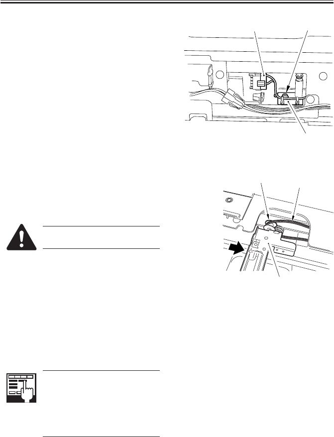
COPYRIGHT
©
2001 CANON INC. 2000 2000 2000 2000 CANON iR2200/iR2800/iR3300 REV.0 MAR. 2001
CHAPTER 2 ORIGINAL EXPOSURE SYSTEM
2-17 R
6) Disconnect the connector [1].
7) Remove the screw [2], and detach the
cable fixing plate [3].
F02-501-03
8) Push the No. 1 mirror base, and move
the No. 2 mirror base [1] as far as the
cut-off in the frame; then, free the cable
[3] from the pulley [2].
When mounting the lamp, take
care not to twist the cable [3].
F02-501-04
5.1.2 After Replacing the Scanning Lamp
Execute ‘CCD auto adjust’ in service
mode, and record the updated CCD adjust-
ment data on the service label.
1.COPIER>FUNCTION>
CCD>CCD-ADJ
CCD Auto Adjust
2. All items under
COPIER>ADJUST>CCD.
CCD Adjustment Data
[1] [2]
[3]
[2]
[1]
[3]
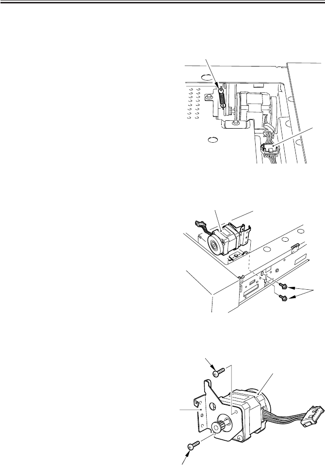
COPYRIGHT
©
2001 CANON INC. 2000 2000 2000 2000 CANON iR2200/iR2800/iR3300 REV.0 MAR. 2001
CHAPTER 2 ORIGINAL EXPOSURE SYSTEM
2-18 R
5.2 Scanner Drive Assembly
5.2.1 Removing the Scanner Motor
1) Remove the copyboard glass. (p. 3-11R)
2) Disconnect the connector [1].
3) Remove the spring [2].
F02-502-01
4) Remove the two screws [1].
5) Detach the belt, and remove the motor
unit [2].
F02-502-02
6) Remove the two screws [1], and detach
the scanner motor [3] from the motor
mounting plate [2].
F02-502-03
[1]
[2]
[1]
[2]
[1]
[1]
[2]
[3]
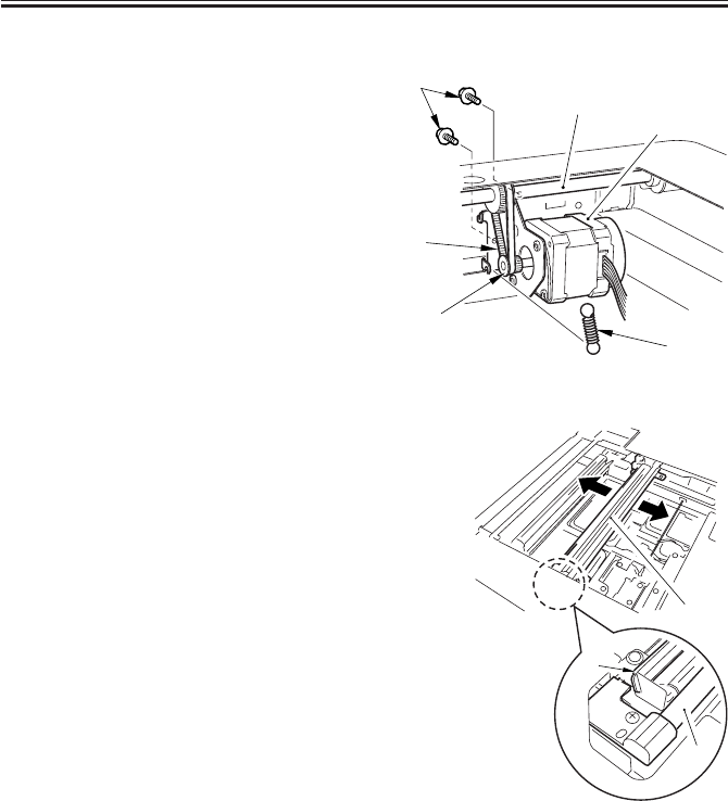
COPYRIGHT
©
2001 CANON INC. 2000 2000 2000 2000 CANON iR2200/iR2800/iR3300 REV.0 MAR. 2001
CHAPTER 2 ORIGINAL EXPOSURE SYSTEM
2-19 R
5.2.2 Mounting the Motor Unit
1) Engage the pulley [2] of the motor unit
[1] with the belt [3].
2) Using two screws [4], mount the motor
unit [1] temporarily.
3) Fit the spring [5] to apply tension to the
belt [3].
4) Check to make sure that the belt [3] is
vertical.
F02-502-04
5) While taking care not to hold the scan-
ning lamp [1] or the reflecting shade
[2], move the No. 1 mirror base [3]
back and forth two to three times to
make a check once again.
F02-502-05
6) Tighten the two screws to secure the
motor unit in place.
[1]
[6]
[2]
[3]
[4]
[5]
[3]
[1]
[2]
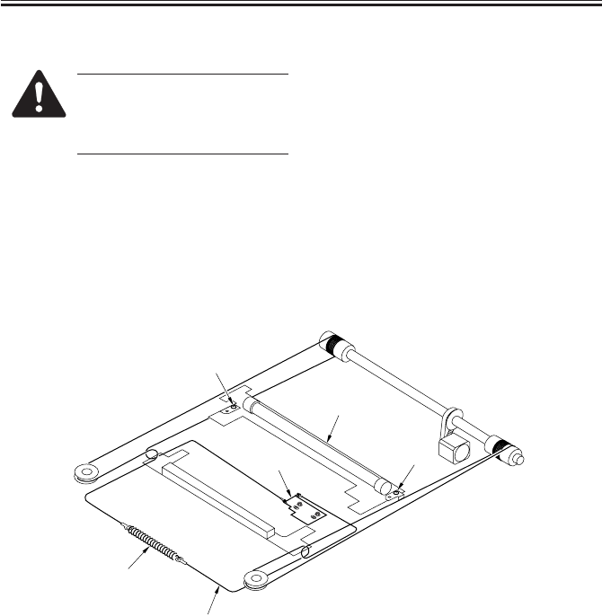
COPYRIGHT
©
2001 CANON INC. 2000 2000 2000 2000 CANON iR2200/iR2800/iR3300 REV.0 MAR. 2001
CHAPTER 2 ORIGINAL EXPOSURE SYSTEM
2-20 R
5.2.3 Removing the Scanner Drive Cable
When replacing the cable, be
sure to obtain the following:
• Mirror positioning tool
(FY9-3009)
1) Remove the reader upper frame. (p. 3-
14R)
2) Remove the two cable fixing screws [2]
of the No. 1 mirror base [1].
3) Remove the spring [3] used to secure
the cable in place.
4) Remove the cable fixing plate [4], and
free the cable [5] from the pulleys.
F02-502-06
[4]
[5]
[1]
[2]
[2]
[3]
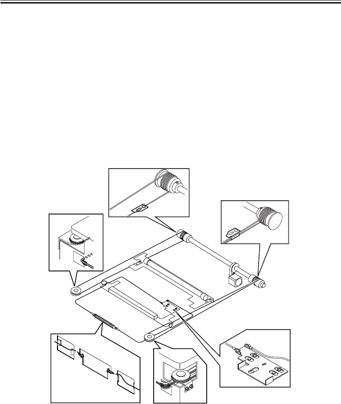
COPYRIGHT
©
2001 CANON INC. 2000 2000 2000 2000 CANON iR2200/iR2800/iR3300 REV.0 MAR. 2001
CHAPTER 2 ORIGINAL EXPOSURE SYSTEM
2-21 R
5.2.4 Routing the Scanner Drive Cable
Route the scanner cable as follows to the pulleys and the hook mirror base:
1) Loosen the screw on the cable fixing plate.
2) Put the ball of the cable into the hole in the drive pulley, and wind the cable firmly so
that it will not turn idly (4 runs inside, 5 runs outside); then, tape it in place. At this
time, check to make sure that the cable fixing is on the inside.
3) Engage the cable with each pulley, and temporarily fix one of its ends to the cable fixing
plate and the other to the hook on the reader frame.
4) Temporarily secure the cable fixing in place to the No. 1 mirror base. (Do not tighten the
screw fully.)
5) Fit the reader upper frame.
6) Adjust the position of the No. 1 and No. 2 mirror bases.
F02-502-07
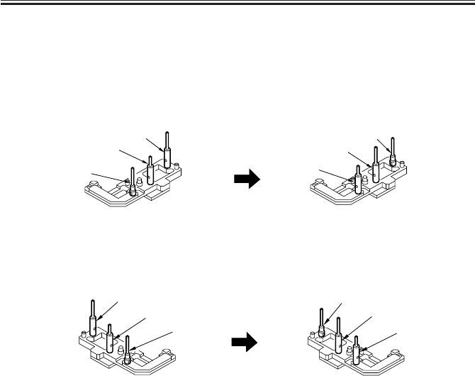
COPYRIGHT
©
2001 CANON INC. 2000 2000 2000 2000 CANON iR2200/iR2800/iR3300 REV.0 MAR. 2001
CHAPTER 2 ORIGINAL EXPOSURE SYSTEM
2-22 R
5.2.5 Adjusting the Position of the No. 1/No. 2 Mirror Base
1) Set the pins of the mirror positioning
tool as indicated:
• For the Front (F marking)
(initial; FY9-3009) (set for the machine)
F02-502-08
• For the Rear (R marking)
(initial; FY9-3009) (set for the machine)
F02-502-09
[A]
[A]
[B]
[B]
[C]
[C]
[A]
[A]
[B]
[B]
[C]
[C]
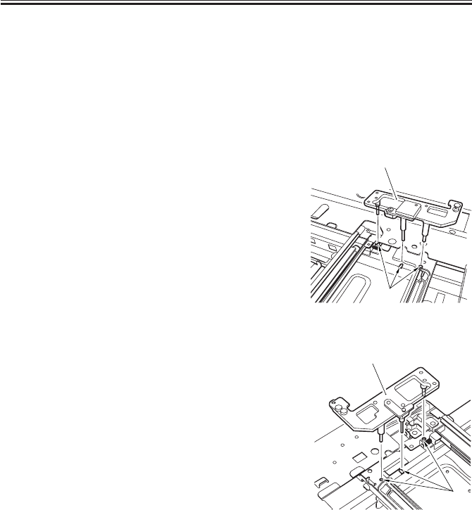
COPYRIGHT
©
2001 CANON INC. 2000 2000 2000 2000 CANON iR2200/iR2800/iR3300 REV.0 MAR. 2001
CHAPTER 2 ORIGINAL EXPOSURE SYSTEM
2-23 R
2) Fit the pins of the mirror positioning
tool (front [2], rear [3]) into the holes
[1] of the rail and the No. 1/No. 2 mir-
ror base. The No. 2 mirror base is ad-
justed in keeping with the back-and-
froth movement of the cable fixing
plate.
Front Side (F marking)
F02-502-10
Rear Side (R marking)
F02-502-11
3) Fix the end of the cable (which is tem-
porarily secured on the hook of the
reader frame) in place using the spring.
4) Fully tighten the screw on the cable fix-
ing plate.
5) Fully tighten the screw on the cable fix-
ing so that it is secured on the No. 1
mirror base.
6) Detach the mirror positioning tool (2
pc.).
[2]
[1]
[3]
[1]
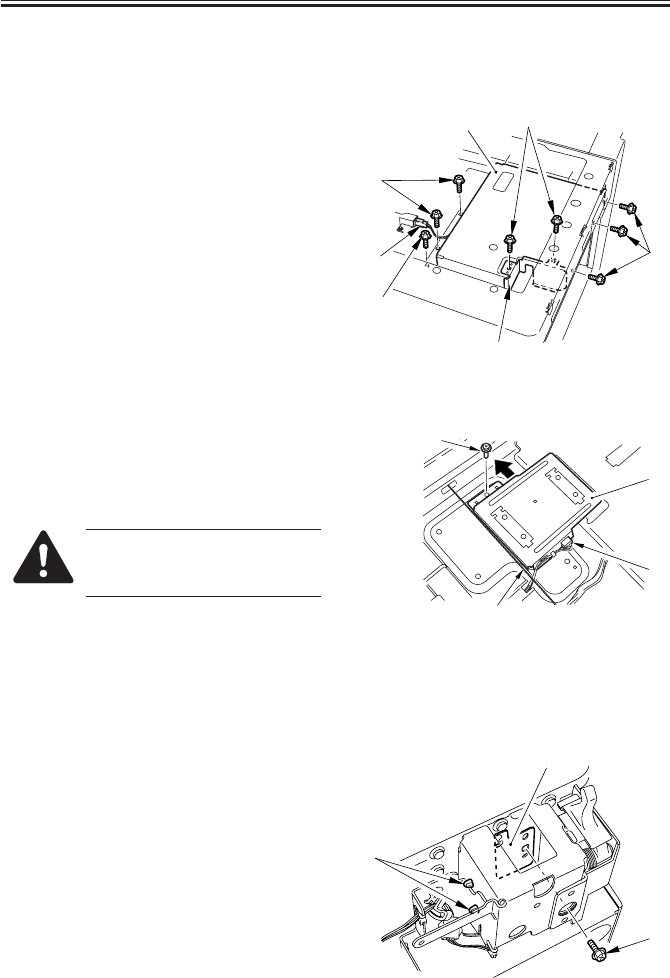
COPYRIGHT
©
2001 CANON INC. 2000 2000 2000 2000 CANON iR2200/iR2800/iR3300 REV.0 MAR. 2001
CHAPTER 2 ORIGINAL EXPOSURE SYSTEM
2-24 R
5.3 Sensors
5.3.1 Removing the Original Detection Unit
1) Remove the copyboard glass. (p. 3-11R)
2) Remove the two screws [1], and detach
the motor shield plate [2].
3) Disconnect the connector [3].
4) Remove the six screws [4], and detach
the CCD shield plate [5].
F02-503-01
5) Remove the screw [1], and disconnect
the connector [2].
6) Shift the original detection unit [3] to
the rear to detach.
When removing it, be sure to
take full care not to damage the
cable [5].
F02-503-02
5.3.2 Removing the HP Sensor
1) Remove the reader rear cover (5
screws).
2) Remove the left support cover.
3) Remove the two harness bands [1].
4) Remove the screw [1], and detach the
sensor mounting plate [2].
F02-503-03
[1]
[3]
[4]
[4]
[4]
[5]
[2]
[1]
[2]
[4]
[3]
[1]
[2]
[3]
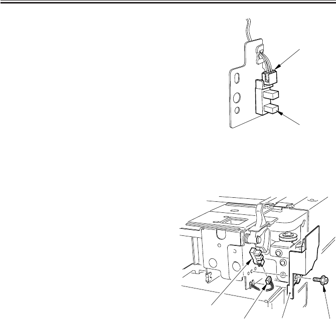
COPYRIGHT
©
2001 CANON INC. 2000 2000 2000 2000 CANON iR2200/iR2800/iR3300 REV.0 MAR. 2001
CHAPTER 2 ORIGINAL EXPOSURE SYSTEM
2-25 R
4) Disconnect the connector [1], and de-
tach the HP sensor [2] from the sensor
mounting plate.
F02-503-04
5.3.3 Removing the Original Cover Sensor
1) Remove the reader rear cover (5
screws).
2) Disconnect the connector [1].
3) Remove the screw [2], and detach the
copyboard sensor cover [3].
4) Remove the copyboard cover sensor [4].
F02-503-05
[1]
[2]
[1] [2][3]
[4]
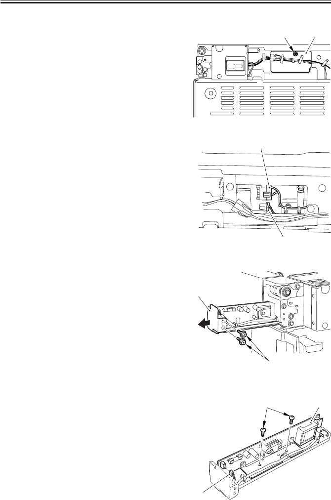
COPYRIGHT
©
2001 CANON INC. 2000 2000 2000 2000 CANON iR2200/iR2800/iR3300 REV.0 MAR. 2001
CHAPTER 2 ORIGINAL EXPOSURE SYSTEM
2-26 R
5.4 PCBs
5.4.1 Removing the Inverter PCB
1) Remove the reader rear cover (5
screws).
2) Remove the screw [1], and detach the
connector cover [2] found at the rear.
F02-504-01
3) Disconnect the two connectors [3].
F02-504-02
4) Remove the two screws [1], and slide
out the inverter unit [2].
F02-504-03
5) Disconnect the connector [1].
6) Remove the two screws [2], and slide
out the inverter PCB [3].
F02-504-04
[1] [2]
[3]
[3]
[1]
[2]
[2]
[1]
[3]

COPYRIGHT
©
2001 CANON INC. 2000 2000 2000 2000 CANON iR2200/iR2800/iR3300 REV.0 MAR. 2001
CHAPTER 3
IMAGE PROCESSING SYSTEM
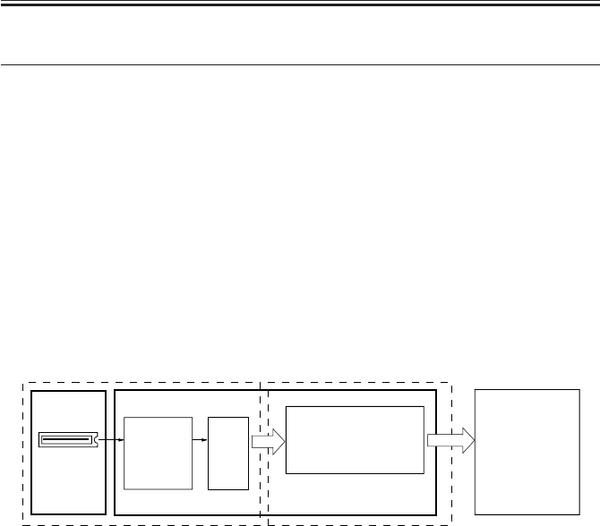
COPYRIGHT
©
2001 CANON INC. 2000 2000 2000 2000 CANON iR2200/iR2800/iR3300 REV.0 MAR. 2001
CHAPTER 3 IMAGE PROCESSING SYSTEM
3-1 R
1 Outline
The major functions of the image processing system are as follows:
[1] CCD (image sensor)
Number of lines: 1
Number of pixels: 7450
Size of pixel: 4.7 × 4.7 µm
[2] Shading Correction
Shading adjustment: executed in service mode
Shading correction: executed for each copy
[3] Auto Density Adjustment (AE)
Executed for each line in main scanning direction.
The image processing system consists of the following functional blocks:
F03-100-01
Each of the PCBs used in the image processing system has the following functions:
[1] CCD/AP PCB. Drives the CCD, performs analog image processing, performs A/D
conversion.
[2] Reader controller PCB. Performs shading correction, performs auto density adjustment
(AE).
CCD
CCD
PCB Reader controller PCB
A/D
conve
-rsion
Shading processing
Analog
image
processing
Analog image processing block
Controller unit
Digital image processing block
Auto density
correction (AE)
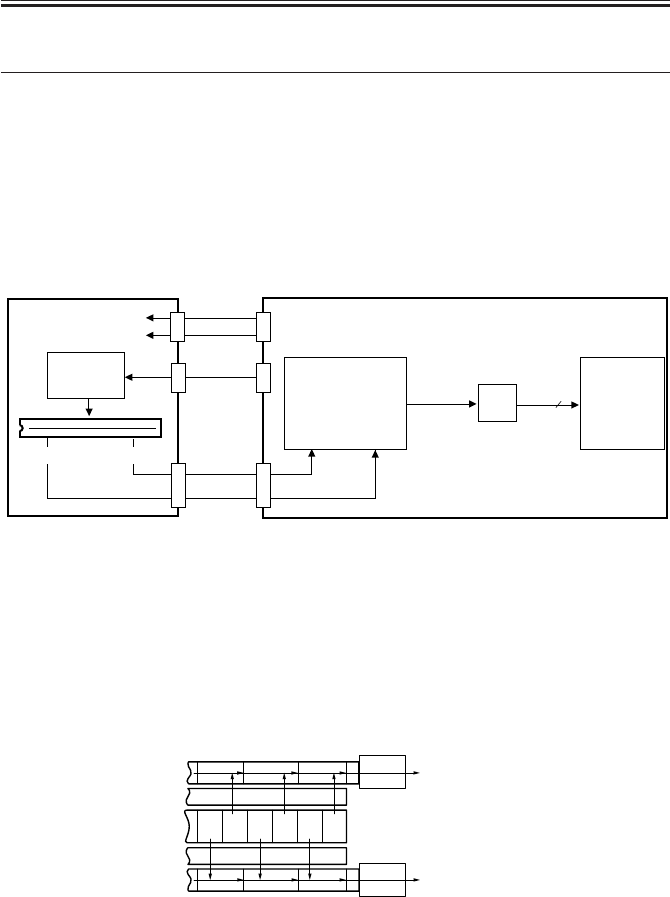
COPYRIGHT
©
2001 CANON INC. 2000 2000 2000 2000 CANON iR2200/iR2800/iR3300 REV.0 MAR. 2001
CHAPTER 3 IMAGE PROCESSING SYSTEM
3-2 R
2 Analog Image Processing
2.1 Outline
Analog image processing is performed by the CCD PCB and the reader controller PCB,
which has the following major functions:
[1] Drives the CCD.
[2] Corrects the gain in the CCD output, corrects offset.
[3] Performs parallel/serial conversion of CCD output.
[4] Performs A/D conversion of CCD output.
F03-201-01
2.2 Driving the CCD
The machine’s CCD sensor is a single-line linear image sensor, and is composed of 7450
pixel photo cells.
The signals subjected to phtoconversion in the light-receiving segment are sent out in two
types of analog signals: even-number (EVEN) pixels and odd-number (ODD) pixels.
F03-202-01 CCD Block Diagram
Shift register
Light receiving
segment
(photodiode)
Shift register
Output buffer
Output buffer
Gate
Gate
123456
Odd-number pixel data
Even-number pixel data
CCD
8
J403
12V
5V
J407
J408
· Gain correction
· Offset correction
· Parallel/serial
conversion
A/D
conver
-sion
Analog image signal
Digital
image
signal
Analog
image
signal
CCD PCB
CCD
driver
Reader controller PCB
Even-number
pixels
Odd-number
pixels
CCD drive
signal
Digital
image
processing
block
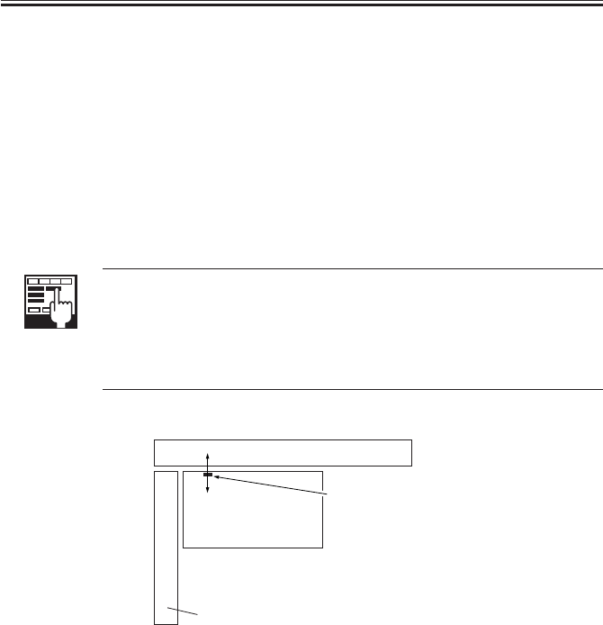
COPYRIGHT
©
2001 CANON INC. 2000 2000 2000 2000 CANON iR2200/iR2800/iR3300 REV.0 MAR. 2001
CHAPTER 3 IMAGE PROCESSING SYSTEM
3-3 R
2.3 Gain Correction and Offset Correction of the CCD Output
To correct discrepancies in the efficiency of photoconversion among pixels, the analog
video signals from the CCD are corrected: in gain correction, the rates of amplification are
standardized; in offset correction, on the other hand, the output voltage in the absence of in-
coming light is set to a specific level.
2.4 A/D Conversion of the CCD Output
The analog video signals of odd-number and even-number pixels after correction are con-
verted into 8-bit digital signals that correspond to specific pixel voltage levels by the A/D
converter.
COPIER/ADJUST>ADJ-XY>ADJ-Y (CCD read start position adjust-
ment)
It is used to adjust the parameter used determining the read start position in
main scanning direction.
Range: 0 to 400
(A change by ‘1’ results in a shift of 0.1 mm.)
F03-205-01
Decrease
Increase
Original
Vertical size plate
Read start position
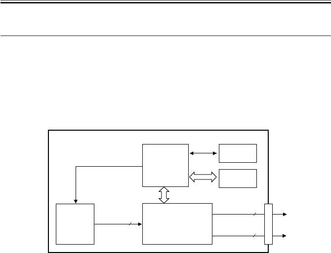
COPYRIGHT
©
2001 CANON INC. 2000 2000 2000 2000 CANON iR2200/iR2800/iR3300 REV.0 MAR. 2001
CHAPTER 3 IMAGE PROCESSING SYSTEM
3-4 R
3 Digital Image Processing
3.1 Outline
Digital image processing is performed by the reader controller PCB, which has the fol-
lowing major functions:
[1] Shading correction
[2] Auto density adjustment (AE)
F03-301-01
3.2 Shading Correction
3.2.1 Outline
The output of the CCD will not necessarily be uniform because of the following factors
even if the density of the original in question is perfectly uniform:
1) The level of sensitivity of a CCD pixel differs from that of another.
2) The level of penetration of light differs between the center and the periphery of a lens.
3) The intensity of the scanning lamp differs between the middle and the ends of the
lamp.
4) The scanning lamp is subject to deterioration.
Shading correction is executed to correct discrepancies in the output of the CCD, and it
may be of either of the following two: shading adjustment used to determine a target level in
service mode and shading correction executed when scanning each original.
To make up for the fluctuations in the intensity of light occurring at short intervals, edge
area gain correction is also executed.
EEP-ROM
SRAM
CPU
8
8
8
J409
Gain/offset
correction data
· Shading correction
· Auto density
correction (AE)
· Serial/parallel
conversion
digital image
signal
Reader controller PCB
digital image
signal
Even-number
pixel
Odd-number
pixel
Target
value
Analog
image
processing
block
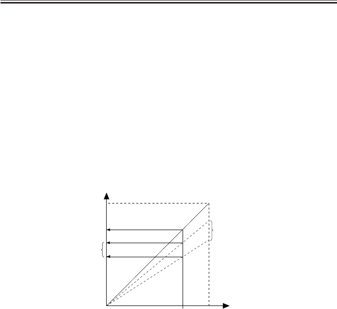
COPYRIGHT
©
2001 CANON INC. 2000 2000 2000 2000 CANON iR2200/iR2800/iR3300 REV.0 MAR. 2001
CHAPTER 3 IMAGE PROCESSING SYSTEM
3-5 R
3.2.2 Shading Adjustment
In this adjustment, the density of white paper and that of the standard white plate are mea-
sured, and the results are stored in memory.
The data is computed for use as the target level during shading correction. The adjustment
is designed for service mode and is used upon installation of the machine, after replacement
of the scanning lamp, or when correcting changes in the intensity of the scanning lamp oc-
curring over time.
3.2.3 Shading Correction
This correction is executed each time an original is scanned. The density of the standard
white plate is measured and the result is compared against the target value stored in the
shading correction circuit. The difference is used as the shading correction value, which will
be used to correct the variation in CCD pixels, thereby ensuring a specific level of image
density.
F03-302-01
CCD output
Original density
Standard white plate
Characteristics
before correction
Target value
Results of
measurement
Characteristics
after correction
White
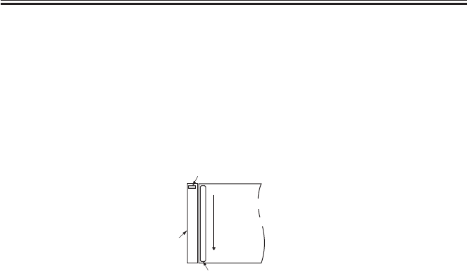
COPYRIGHT
©
2001 CANON INC. 2000 2000 2000 2000 CANON iR2200/iR2800/iR3300 REV.0 MAR. 2001
CHAPTER 3 IMAGE PROCESSING SYSTEM
3-6 R
3.2.4 Edge Gain Correction (ADF in use)
In stream reading with the ADF in use, the No. 1 mirror base is fixed in position. To
check for changes in the intensity of the scanning lamp, the edge gain correction plate (gray;
mounted at the edge of read position) is read, and a gain that enables the attainment of a
specific intensity is computed.
The result is used to correct the data which otherwise would be affected by changes in the
intensity of light.
F03-302-02
1 pixel
7450 pixels
Edge gain correction plate
Standard white plate (for shading)
Copyboard glass
Reading
glass
Main scanning
direction
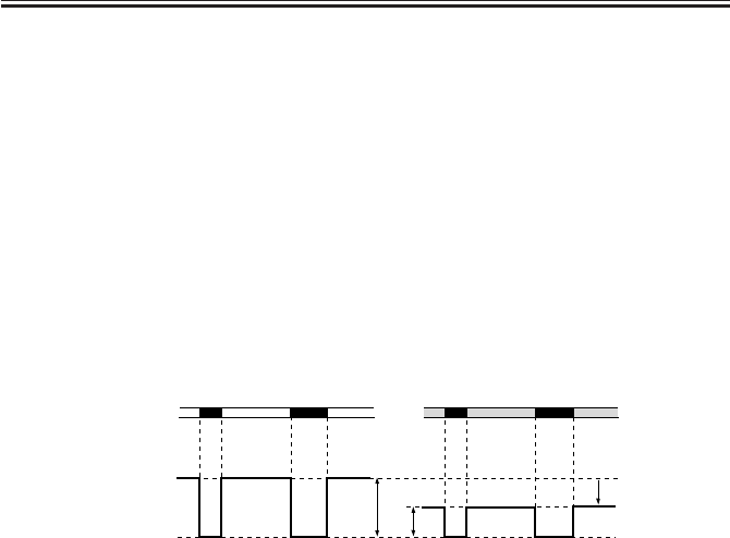
COPYRIGHT
©
2001 CANON INC. 2000 2000 2000 2000 CANON iR2200/iR2800/iR3300 REV.0 MAR. 2001
CHAPTER 3 IMAGE PROCESSING SYSTEM
3-7 R
3.3 Auto Density Adjustment (AE)
3.3.1 Outline
As in the case of a newspaper, some originals have a dark background. Auto density cor-
rection is executed to reproduce the information (text, graphics) of such originals by remov-
ing the background.
This adjustment is enabled in density auto mode or when text mode is selected and data is
processed by the ABC circuit.
3.3.2 ABC Circuit
A colored background is identified as being white by changing the height of the dynamic
range according to the chromatic level of the background as shown in the following figure
for the CCD output level (8-it) of digital image signals (A/D converted).
F03-303-01
FFh (white)
00h (black)
FFh (white)
00h (black)
Surface of original
White Background Original Colored Original
AB
A : dynamic range of white-background original.
B : dynamic range of colored-background original.
Output level

COPYRIGHT
©
2001 CANON INC. 2000 2000 2000 2000 CANON iR2200/iR2800/iR3300 REV.0 MAR. 2001
CHAPTER 3 IMAGE PROCESSING SYSTEM
3-8 R
3.4 Related Service Mode
COPIER>FUNCTION>CCD>CCD-ADJ (shading auto adjustment)
Execute the mode after replacing the CCD unit, scanning lamp, reader con-
troller PCB, or standard white plate.
COPIER>ADJUST>CCD>PPR (density data of standard white pa-
per)
COPIER>ADJUST>CCD>PLT (density data of standard white plate)
COPIER>AJDUST>CCD>GAIN-E/O (gain adjustment input of CCD
output)
COPIER>ADJUST>CCD>OFST-E/O (offset adjustment input of CCD
output)
COPIER>ADJUST>CCD>SH_RATIO (white level ratio data of stan-
dard white plate and standard white paper during shading correc-
tion)
If a faulty image is generated after executing shading auto adjustment, enter
the parameter values indicated on the service label.
COPIER>ADJUST>AE>AE-TBL (text density adjustment for real-
time AE mode)
Use it to change the parameter for adjustment of the density correction
curve (for real-time AE mode; 10 steps).
Range: 0 to 9 (default: 4)
F03-304-01
White
WhiteOriginal density
Copy density
Lower setting
decreases text density Higher setting
increases text density

COPYRIGHT
©
2001 CANON INC. 2000 2000 2000 2000 CANON iR2200/iR2800/iR3300 REV.0 MAR. 2001
CHAPTER 3 IMAGE PROCESSING SYSTEM
3-9 R
4 Disassembly and Assembly
The discussions that follow cover the machine’s mechanical characteristics and how to
disassemble/assemble the machine. Keep the following in mind whenever you work with the
machine:
1. The power plug must remain disconnected for safety when disassembling/assembling
the machine.
2. Unless otherwise noted, the machine may be assembled by reversing the steps used to
disassemble it.
3. The screws must be identified by type (length, diameter) and location.
4. The mounting screws used for the grounding wire and the varistors come with a washer,
which must not be left out when assembling the machine.
5. As a rule, the machine must not be operated with any of its parts removed.
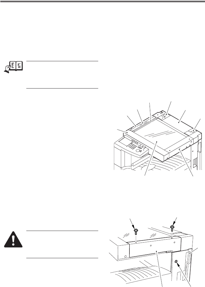
COPYRIGHT
©
2001 CANON INC. 2000 2000 2000 2000 CANON iR2200/iR2800/iR3300 REV.0 MAR. 2001
CHAPTER 3 IMAGE PROCESSING SYSTEM
3-10 R
4.1 External Covers
4.1.1 External Covers
Remove the covers as follows when
cleaning, checking, or repairing the inside
of the machine:
REF.
Those covers that can be de-
tached by merely removing the
mounting screws are left out of
the discussions.
[1] Reader front cover (2 screws)
[2] Reader left cover (2 screws)
[3] Reading glass
[4] Guide base (3 screws)
[5] Left support cover
[6] Reader rear cover (5 screws)
[7] Right support cover
[8] Reader right cover (2 screws)
[9] Copyboard glass
F03-401-01
4.1.2 Removing the Reader Right Cover
1) Remove the two screws [1], and detach
the reader right cover [2].
When mounting the reader right
cover [2], loosen the top screw
[4] of the right rear cover [3]
first.
F03-401-02
[1]
[2]
[3]
[4] [5]
[6]
[7]
[8]
[9]
[1][1]
[2]
[3]
[4]
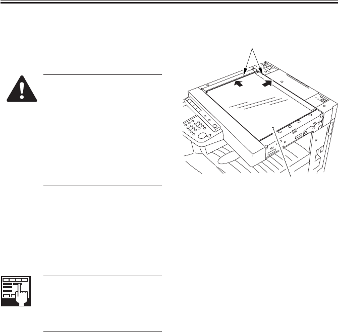
COPYRIGHT
©
2001 CANON INC. 2000 2000 2000 2000 CANON iR2200/iR2800/iR3300 REV.0 MAR. 2001
CHAPTER 3 IMAGE PROCESSING SYSTEM
3-11 R
4.1.3 Removing the Copyboard Glass
1) Remove the reader right cover. (See
item 4.1.2.)
2) Remove the copyboard glass [1].
• When mounting, butt the
copyboard glass [1] against
the vertical/horizontal size
plate [2]. If not done prop-
erly, the shadow of the size
plate will appear on images
made in enlargement mode.
(After mounting, make an
800% enlargement copy to
check.)
F03-401-03
4.1.4 After Mounting the Copyboard Glass
Execute 'optimum position auto adjust-
ment on standard white plate' in service
mode.
COPIER>FUNCTION>CCD>
SH-PS-ST
Use it to execute optimum posi-
tion auto adjustment for the
standard white plate.
[2]
[1]
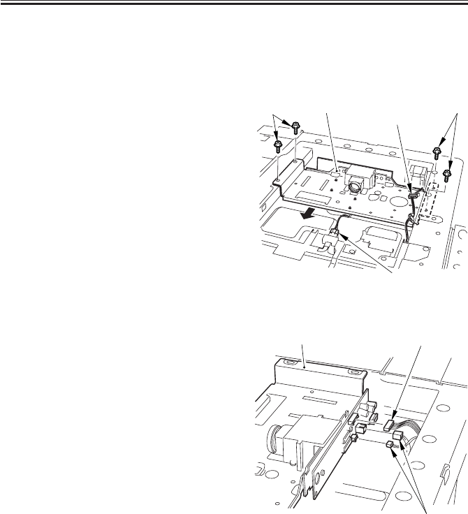
COPYRIGHT
©
2001 CANON INC. 2000 2000 2000 2000 CANON iR2200/iR2800/iR3300 REV.0 MAR. 2001
CHAPTER 3 IMAGE PROCESSING SYSTEM
3-12 R
4.2 CCDs
4.2.1 Removing the CCD Unit
1) Remove the original detection unit. (p.
2-24R)
2) Remove the four screws [1], and dis-
connect the connector [2].
3) Disconnect the connector [3] of the
scanner motor, and detach the harness.
4) Shift the CCD unit [4] to the left.
F03-402-01
5) Disconnect the three connectors [1], and
detach the CCD unit [2].
F03-402-02
[1] [1]
[2]
[3]
[4]
[2] [1]
[1]

COPYRIGHT
©
2001 CANON INC. 2000 2000 2000 2000 CANON iR2200/iR2800/iR3300 REV.0 MAR. 2001
CHAPTER 3 IMAGE PROCESSING SYSTEM
3-13 R
4.2.2 Points to Note When Replacing the CCD Unit
Execute ‘CCD auto adjustment’ and
‘edge gain correction position auto adjust-
ment’ in service mode; then, record the up-
dated CCD adjustment data on the service
label.
1) COPIER>FUNCTION>
CCD>CCD-ADJ
CCD Auto Adjustment
2) COPIER>FUNCTION>
CCD>EGGN-POS
Edge Gain Correction Auto
Adjustment
3) all items under
COPIER>ADJUST>CCD
CCD Adjustment Data
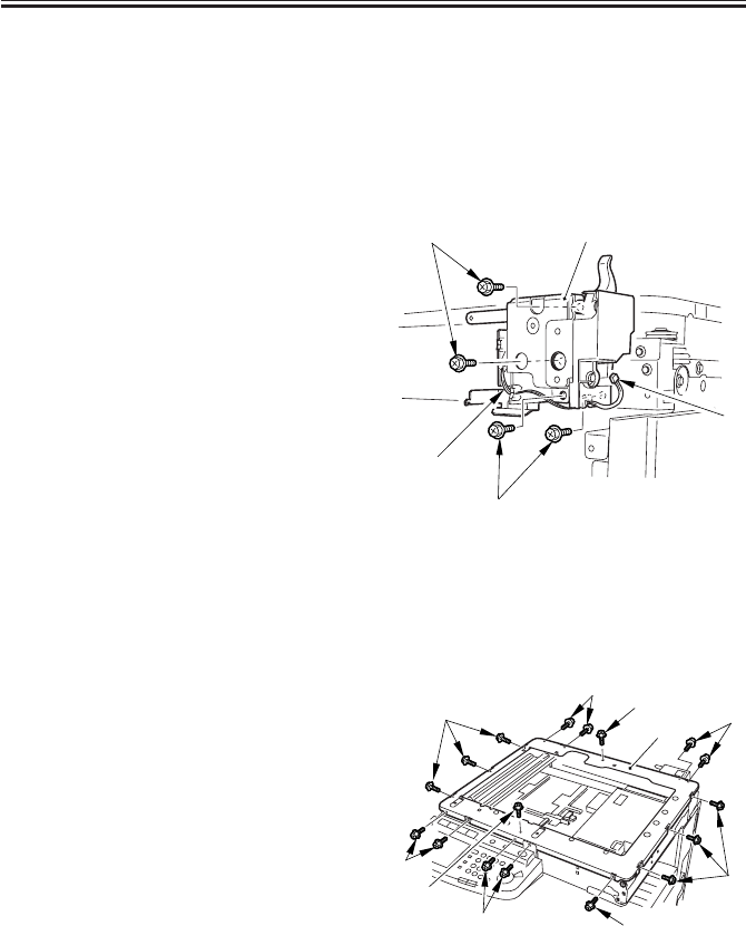
COPYRIGHT
©
2001 CANON INC. 2000 2000 2000 2000 CANON iR2200/iR2800/iR3300 REV.0 MAR. 2001
CHAPTER 3 IMAGE PROCESSING SYSTEM
3-14 R
4.3 Frames
4.3.1 Removing the Left ADF Base Unit
1) Remove the reader rear cover (5 screws)
and the left support cover.
2) Remove the rear cover (7 screws) of the
printer unit. (See the descriptions for
the printer unit.)
3) Disconnect the connector [1], and de-
tach the harness [2].
4) Remove the four screws [3], and detach
the left ADF base unit [4].
F03-403-01
4.3.2 Removing the Reader Upper Frame
1) Remove the left ADF base unit. (See
item 4.3.1.)
2) Remove the two screws [1] from the top
face.
3) Remove the 15 screws [2] from the side
face.
4) Remove the reader upper frame [3].
F03-403-02
[1]
[3]
[3]
[2]
[4]
[1]
[1]
[2]
[2]
[2]
[2] [2]
[2]
[2]
[3]
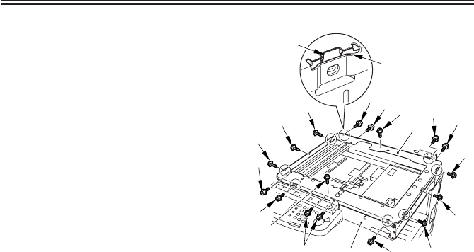
COPYRIGHT
©
2001 CANON INC. 2000 2000 2000 2000 CANON iR2200/iR2800/iR3300 REV.0 MAR. 2001
CHAPTER 3 IMAGE PROCESSING SYSTEM
3-15 R
4.3.3 Mounting the Reader Upper Frame
1) Fit the eight claws [2] of the reader
frame [1] (circled) into the cut-offs [4]
in the reader upper frame [3]; take care
so that the engagement is secure.
2) Fit the eight screws [5] of the claw as-
sembly first.
3) Fit the seven screws [6] of the side.
4) Lastly, fit the two screws [7] on the top
face.
F03-403-03
[4]
[2]
[7]
[7]
[5] [6]
[5]
[6]
[5]
[5]
[6]
[6] [5]
[6]
[6]
[5]
[5]
[3]
[1] [5]

COPYRIGHT
©
2001 CANON INC. 2000 2000 2000 2000 CANON iR2200/iR2800/iR3300 REV.0 MAR. 2001
CHAPTER 3 IMAGE PROCESSING SYSTEM
3-16 R
4.4 PCBs
4.4.1 Removing the Reader Controller PCB
See the descriptions for the printer unit.
4.4.2 When Replacing the Reader Controller PCB
See “Troubleshooting”>Chapter 4 “Troubleshooting Image Faults/Malfunctions” >6.7
“Variable Resistors (VR), Light-Emitting Diodes, and Check Pins by PCB”

COPYRIGHT
©
2001 CANON INC. 2000 2000 2000 2000 CANON iR2200/iR2800/iR3300 REV.0 MAR. 2001
PRINTER UNIT

COPYRIGHT
©
2001 CANON INC. 2000 2000 2000 2000 CANON iR2200/iR2800/iR3300 REV.0 MAR. 2001
CONTENTS
P1
Contents
CHAPTER 1 INTRODUCTION
CHAPTER 2 SEQUENCE OF OPERATIONS
1 Safety..............................................1-1P
1.1 Safety of Laser Light ............... 1-1P
1.2 CDRH Ordinances ...................1-1P
1.3 Handling the Laser System ......1-3P
1.4 Safety of Toner .........................1-4P
2 Image Formation System ...............1-5P
2.1 Outline .....................................1-5P
1 Basic Operations ............................ 2-1P
1.1 Functional Construction ..........2-1P
1.2 Outline for the Electrical Circuitry
.................................................2-2P
1.2.1 Outline ...............................2-2P
1.2.2 DC Controller PCB ........... 2-2P
1.3 Basic Sequence of Operations
.................................................2-3P
1.3.1 Basic Sequence of Operations at
Power-On ...........................2-3P
1.4 Controlling the Main Motor (M2)
.................................................2-5P
1.4.1 Outline ...............................2-5P
1.5 Inputs to and Outputs from the Ma-
jor PCBs ...................................2-6P
1.5.1 Wiring Diagram of the Major
PCBs ..................................2-6P
CHAPTER 3 LASER EXPOSURE SYSTEM
1 Outline of Operations ..................... 3-1P
1.1 Outline ..................................... 3-1P
1.2 Sequence of Operations (laser expo-
sure system) ............................. 3-3P
2 Generating Sync Signals ................ 3-3P
2.1 Outline ..................................... 3-3P
2.2 Flow of Sync signals ................3-4P
3 Laser Driver Circuit ....................... 3-5P
3.1 Controlling the Laser Unit .......3-5P
4 Controlling the Laser Scanner Motor
........................................................3-7P
4.1 Outline .....................................3-7P
5 Disassembly and Assembly ............3-8P
5.1 Laser Scanner Assembly ..........3-9P
5.1.1 Removing the Laser Unit .........3-9P
CHAPTER 4 IMAGE FORMATION SYSTEM
1 Outline of Processes .......................4-1P
1.1 Outline ..................................... 4-1P
1.2 Basic Sequence of Operations (im-
age formation system) ..............4-3P
2 Controlling the Primary Charging
Roller Bias ......................................4-4P
2.1 Outline .....................................4-4P
2.2 Turning On/Off the Bias ..........4-5P
2.2.1 DC Bias .............................4-5P

COPYRIGHT
©
2001 CANON INC. 2000 2000 2000 2000 CANON iR2200/iR2800/iR3300 REV.0 MAR. 2001
CONTENTS
P2
2.2.2 AC Bias .............................. 4-5P
2.3 Controlling the Current Voltage/
Current to a Specific Level ...... 4-5P
2.3.1 Controlling the DC Bias to a
Specific Level .................... 4-5P
2.3.2 Controlling the AC Bias to a
Specific Current Level .......4-5P
2.4 Temperature Correction of the DC
Bias ..........................................4-6P
2.5 Humidity Correction of the AC Bias
.................................................4-6P
2.6 Controlling the Detection of the
Photosensitive Drum Resistance
(APVC control) ........................4-7P
3 Controlling the Transfer Charging
Roller Bias ......................................4-9P
3.1 Outline .....................................4-9P
3.2 Turning On/Off the Bias ........4-10P
3.3 Controlling the Detection of the
Transfer Charging Roller Resistance
(ATVC control) ......................4-10P
3.4 Controlling the Output by Operat-
ing Mode ................................ 4-11P
3.4.1 Types of Modes ...............4-11P
3.4.2 Turning On/Off the Cleaning
Bias ..................................4-12P
3.5 Controlling the Output ........... 4-13P
4 Controlling the Separation Static Elimi-
nator Bias .....................................4-14P
4.1 Outline ...................................4-14P
4.2 Turning On/Off the Bias ........4-15P
4.3 Controlling the Bias to a Specific
Voltage Level .........................4-15P
4.4 Controlling the Output by Paper
Type and Environment Sensor (hu-
midity) .................................... 4-15P
5 Controlling the Transfer Guide Bias
......................................................4-16P
5.1 Transfer Guide Bias ...............4-16P
6 Primary Charging Roller Cleaning
Mechanism ...................................4-17P
6.1 Outline ...................................4-17P
7 Developing Assembly ..................4-18P
7.1 Outline ...................................4-18P
7.2 Controlling the Developing Bias
...............................................4-19P
7.2.1 Outline .............................4-19P
7.2.2 Controlling the DC Developing
Bias ..................................4-20P
7.2.3 Controlling the AC Developing
Bias ..................................4-20P
7.2.4 Controlling the Level of the DC
Developing Bias ..............4-20P
7.3 Detecting the Level of Toner
...............................................4-21P
8 Drum Cleaner ...............................4-22P
8.1 Outline ................................... 4-22P
8.2 Monitoring the Waste Toner Case
...............................................4-24P
8.3 Locking of the Waste Toner
Feedscrew ..............................4-25P
9 Disassembly and Assembly ..........4-26P
9.1 Pre-Exposure Lamp Unit .......4-27P
9.1.1 Removing the Pre-Exposure
Lamp Unit ........................4-27P
9.2 Photosensitive Drum .............. 4-28P
9.2.1 Removing the Drum Unit 4-28P
9.2.2 Cleaning the Photosensitive
Drum ................................4-29P
9.3 Transfer Charging Roller .......4-30P
9.3.1 Removing the Transfer Charg-
ing Roller .........................4-30P
9.4 Charging Roller Solenoid ......4-31P
9.4.1 Removing the Charging Roller
Solenoid (SL6) ................4-31P
9.5 Developing Assembly ............4-33P
9.5.1 Removing the Developing As-
sembly.............................. 4-33P
9.5.2 Removing the Grip Assembly
.........................................4-34P
9.5.3 Removing the Toner Sensor
.........................................4-34P
9.5.4 Removing the Developing As-
sembly Upper Cover ........4-34P
9.5.5 Removing the Blade Base Unit
.........................................4-35P
9.5.6 Removing the Developing Cyl-
inder .................................4-35P

COPYRIGHT
©
2001 CANON INC. 2000 2000 2000 2000 CANON iR2200/iR2800/iR3300 REV.0 MAR. 2001
CONTENTS
P3
9.5.7 Positioning the Developing As-
sembly Magnetic Seal......4-38P
9.5.8 Mounting the Developing As-
sembly Blade ...................4-38P
9.6 Removing the Paper Lint .......4-39P
9.6.1 Removing the Paper Lint
.........................................4-39P
CHAPTER 5 PICKUP/FEEDING SYSTEM
1 Outline ............................................5-1P
1.1 Specifications and Construction
.................................................5-1P
1.2 Arrangement of Rollers ...........5-2P
1.3 Arrangement of Motors, Clutches,
and Solenoids ........................... 5-3P
1.4 Arrangement of Sensors ..........5-4P
2 Detecting Jams ...............................5-5P
2.1 Sequence of Operations (jam detec-
tion) ..........................................5-5P
2.1.1 Delay Jam .......................... 5-5P
2.1.2 Stationary Jam ...................5-7P
2.1.3 Jam History ........................5-7P
3 Pickup Assembly ............................5-8P
3.1 Pickup Control System ............ 5-8P
3.2 Outline ..................................... 5-9P
3.3 Sequence of Operations (pickup)
...............................................5-10P
3.4 Operation of the Cassette Lifter
...............................................5-11P
3.4.1 Operation of the Lifter During
Printing ............................5-11P
3.4.2 Releasing the Lifter .........5-12P
3.5 Cassette Pickup Operation .....5-13P
3.5.1 Rotating the Pickup Roller
.........................................5-13P
3.5.2 Switching the Pickup Roller
Drive ................................5-13P
3.5.3 Pickup Roller Shaft Reference
.........................................5-13P
3.6 Moving Up/Down the Pickup
Roller .....................................5-15P
3.7 Pickup Retry Operation .........5-16P
3.7.1 Conditions for Detecting a De-
lay ....................................5-16P
3.7.2 Paper Retraction .............. 5-17P
3.8 Operation Other Than Cassette
Pickup (standby) ....................5-18P
3.8.1 Moving Up the Lifter/Moving
Down the Pickup Roller Shaft
(cassette slid in) ............... 5-18P
3.8.2 Moving Up the Pickup Roller
Shaft and Releasing the Separa-
tion Roller Pressure (cassette
slid out) ............................5-20P
3.9 Detecting the Level of Paper ... 5-22P
3.10 Detecting the Presence/Absence of
Paper Inside the Cassette .......5-23P
4 Identifying the Size of Paper........5-24P
4.1 Identifying the Size ................5-24P
4.2 AB-/Inch-Setting Switch .......5-24P
4.3 Paper Size............................... 5-25P
4.4 Paper Size List ....................... 5-26P
5 Multifeeder ...................................5-27P
5.1 Outline ...................................5-27P
5.2 Identifying the Size of Paper in the
Multifeeder.............................5-28P
5.2.1 Detecting the Width of Paper
.........................................5-28P
5.2.2 Rear/Front Registration ...5-28P
5.2.3 Identifying the Length of Paper
.........................................5-28P
6 Controlling the Registration Roller
......................................................5-29P
6.1 Outline ...................................5-29P
6.2 Control System ...................... 5-29P
9.6.2 When Removing the Paper Lint
.........................................4-39P
9.7 Waste Toner Case ...................4-40P
9.7.1 Replacing the Waste Toner Case
.........................................4-40P
9.7.2 Cleaning the Waste Toner Case
.........................................4-41P

COPYRIGHT
©
2001 CANON INC. 2000 2000 2000 2000 CANON iR2200/iR2800/iR3300 REV.0 MAR. 2001
CONTENTS
P4
7 Double-Sided Printing .................5-30P
7.1 Through-Path Operation ........5-30P
7.2 Outline of Operations ............5-31P
7.3 Detecting the Horizontal Registra-
tion Position ...........................5-33P
7.3.1 Outline .............................5-33P
7.3.2 Operation .........................5-34P
8 Controlling the Pickup Assembly Motor
......................................................5-35P
8.1 Pickup Assembly Motor ........5-35P
9 Disassembly and Assembly .......... 5-36P
9.1 Pickup Assembly ..........................5-37P
9.1.1 Removing the Pickup Assembly
.........................................5-37P
9.1.2 Removing the Pickup/Feeding/
Separation Rollers ...........5-38P
9.1.3 Removing the Pickup Solenoid
.........................................5-38P
9.1.4 Removing the Frame Lid
.........................................5-39P
9.1.5 Removing the Pickup Motor
.........................................5-40P
9.1.6 Remove the Vertical Path Cultch
.........................................5-40P
9.1.7 Removing the Horizontal Regis-
tration Sensor Shift Motor
.........................................5-41P
9.1.8 Checking the Image Rear Front
Position ............................5-42P
9.1.9 Adjusting the Cassette Rear
Front Registration ............5-42P
9.2 Multifeeder Tray Assembly ... 5-44P
9.2.1 Removing the Multifeeder Tray
Assembly .........................5-44P
9.2.2 Removing the Pickup Cover
.........................................5-45P
9.2.3 Removing the Multifeeder Tray
Pickup Roller ...................5-45P
9.2.4 Removing the Separation Pad
.........................................5-46P
9.2.5 Attaching the Timing Belt of the
Multifeeder Tray .............. 5-47P
9.2.6 Checking the Image Rear Front
Position ............................5-47P
9.2.7 Adjusting the Registration for
the Multifeeder Rear Front
.........................................5-47P
9.3 Feeding Assembly .................. 5-49P
9.3.1 Removing the Feeding Assem-
bly ....................................5-49P
9.3.2 Mounting the Feeding Assem-
bly ....................................5-50P
9.4 Registration Roller Assembly 5-51P
9.4.1 Removing the Registration
Roller ...............................5-51P
CHAPTER 6 FIXING SYSTEM
1 Outline of Operations ..................... 6-1P
1.1 Outline .....................................6-1P
2 Fixing Drive System ......................6-4P
2.1 Outline .....................................6-4P
2.2 Controlling the Fixing Roller Drive
.................................................6-4P
2.3 Controlling the Fixing Film Speed
.................................................6-5P
3 Controlling the Fixing Temperature6-6P
3.1 Outline .....................................6-6P
3.2 Temperature Control ................ 6-7P
3.2.1 Fixing Temperature Control
...........................................6-8P
3.3 Detecting Errors .......................6-9P
4 Disassembly and Assembly ..........6-11P
4.1 Fixing Assembly ....................6-12P
4.1.1 Removing the Delivery Cover
.........................................6-12P
4.1.2 Removing the Riser Guide
.........................................6-12P
4.1.3 Removing the Fixing Assembly
.........................................6-13P

COPYRIGHT
©
2001 CANON INC. 2000 2000 2000 2000 CANON iR2200/iR2800/iR3300 REV.0 MAR. 2001
CONTENTS
P5
CHAPTER 7 EXTERNALS AND CONTROLS
1 Control Panel..................................7-1P
1.1 Outline ..................................... 7-1P
2 Fans ................................................7-2P
2.1 Arrangement, Functions, and Error
Codes .......................................7-2P
2.2 Operation ................................. 7-4P
2.2.1 2-Speed Control .................7-4P
2.2.2 Sequence of Operations ..... 7-4P
3 Power Supply .................................7-5P
3.1 Power Supply ...........................7-5P
3.1.1 Outline ...............................7-5P
3.1.2 Power Outputs ...................7-7P
3.2 Rated Outputs of the Main Power
Supply PCB .............................7-8P
3.3 Rated Output of the Composite
Power Supply PCB .................. 7-8P
3.4 Rated Outputs of the Accessories
Power Supply PCB .................. 7-9P
3.5 Protective Functions...............7-10P
4 Others ...........................................7-11P
4.1 Silent Mode ............................7-11P
5 Disassembly and Assembly ..........7-12P
5.1 External Covers...................... 7-13P
5.1.1 Removing the Front Cover
.........................................7-14P
5.1.2 Removing the Inside Cover
.........................................7-14P
5.1.3 Removing the Support Cover
.........................................7-15P
5.2 Control Panel .........................7-16P
5.2.1 Removing the Control Panel
.........................................7-16P
5.3 PCBs ...................................... 7-17P
5.3.1 Removing the DC Controller
PCB..................................7-17P
5.3.2 Points to Note When Replacing
the DC Controller PCB....7-17P
5.3.3 Removing the Controller Cover
.........................................7-17P
5.3.4 Removing the HDD .........7-18P
5.3.5 Removing the HDD Unit
.........................................7-19P
5.3.6 Removing the Controller Box
Unit ..................................7-19P
5.3.7 Removing the Reader Control-
ler PCB ............................ 7-20P
5.3.8 When Replacing the Reader
Controller PCB ................7-20P
5.3.9 Removing the Main Controller
PCB..................................7-20P
5.3.10 When Replacing the Main Con-
troller PCB ....................... 7-21P
5.3.11 Removing the Composite Power
Supply ..............................7-21P
5.3.12 Removing the Accessories
Power Supply...................7-21P
5.3.13 Removing the Main Power Sup-
ply ....................................7-22P
4.1.4 Removing the Fixing Stepped
Gear .................................6-13P
4.1.5 Removing the Fixing Film Unit
.........................................6-13P
4.1.6 Removing the Roller Bushing,
Conducting Rubber, and Fixing
Roller ...............................6-14P
4.1.7 Removing the Cleaning Roller
Unit ..................................6-16P
4.1.8 Removing the Lower Guide
Ribs ..................................6-16P
4.1.9 Removing the Fixing Drive Unit
.........................................6-17P
4.1.10 Mounting the Locking Cam
Unit ..................................6-17P

COPYRIGHT
©
2001 CANON INC. 2000 2000 2000 2000 CANON iR2200/iR2800/iR3300 REV.0 MAR. 2001
CONTENTS
P6
CHAPTER 8 PAPER DECK-L1
1.1 Pickup ...................................... 8-1P
1.1.1 Outline ...............................8-1P
1.1.2 Pickup Operation ...............8-1P
1.1.3 Sequence of Pickup Operations
(deck) .................................8-3P
1.2 Detecting Paper in the Deck ....8-4P
1.2.1 Detecting the Presence/Absence
of Paper ..............................8-4P
1.2.2 Switching the Deck Paper Size
...........................................8-4P
1.2.3 Detecting the Level of Paper in
the Deck .............................8-5P
1.3 Deck Lifter ............................... 8-6P
1.3.1 Detecting the Presence/Absence
of Paper ..............................8-6P
1.3.2 Indicating the Level of Paper
(deck front cover) .............. 8-8P
1.4 Opening/Closing of the Compart-
ment .........................................8-9P
1.4.1 Opening/Closing of the Com-
partment .............................8-9P
1.4.2 Sequence of Operations (open-
ing/closing of the compartment)
.........................................8-10P
1.5 Controlling the Deck Motor ....8-11P
1.5.1 Controlling the Deck Main Mo-
tor (M1D).........................8-11P
1.5.2 Controlling the Deck Lifter Mo-
tor (M2D).........................8-12P
2 Detecting Jams .............................8-14P
2.1 Outline ...................................8-14P
3 Disassembly and Assembly .......... 8-16P
3.1 External Covers...................... 8-17P
3.1.1 Sliding Out the Compartment
.........................................8-17P
3.1.2 Removing the Front Cover
.........................................8-18P
3.1.3 Removing the Rear Cover
.........................................8-20P
3.1.4 Removing the Right Cover
.........................................8-21P
3.1.5 Removing the Front Upper
Cover ...............................8-21P
3.1.6 Removing the Upper Cover
.........................................8-22P
3.2 Paper Deck Body ...................8-23P
3.2.1 Removing the Deck from the
Host Machine...................8-23P
3.2.2 Removing the Compartment
.........................................8-25P
3.2.3 Changing the Deck Paper Size
.........................................8-27P
3.2.4 After Changing the Deck Paper
Size ..................................8-27P
3.2.5 Checking the Image Rear Front
Position ............................8-28P
3.2.6 Adjusting the Cassette Rear
Front Registration ............8-28P
3.2.7 Adjusting the Registration for
the Deck ...........................8-29P
3.2.8 Adjusting the Position of the
Support Member ..............8-29P
3.3 Drive System..........................8-30P
3.3.1 Removing the Deck Pickup
Clutch (CL2D) ................. 8-30P
3.3.2 Removing the Deck Feeding
Clutch (CL1D) ................. 8-30P
3.3.3 Removing the Deck Main Mo-
tor (M1D).........................8-31P
3.3.4 Removing the Deck Lifter Mo-
tor (M2D).........................8-31P
3.3.5 Removing the Lifter Cable
(deck front) ......................8-32P
3.3.6 Removing the Lifter Cable
(deck rear) ........................ 8-34P
3.3.7 Routing the Lifter Cable ..8-36P
3.4 Feeding Mechanism ...............8-37P
3.4.1 Removing the Deck Pickup
Unit ..................................8-37P
3.4.2 Removing the Deck Pickup
Roller ...............................8-37P
3.4.3 Mounting the Deck Pickup
Roller ...............................8-38P
3.4.4 Removing the Deck Pickup/
Feeding Roller .................8-38P

COPYRIGHT
©
2001 CANON INC. 2000 2000 2000 2000 CANON iR2200/iR2800/iR3300 REV.0 MAR. 2001
CONTENTS
P7
CHAPTER 9 CASSETTE FEEDING UNIT-W1
1 Outline ............................................9-1P
1.1 Specifications and Construction
.................................................9-1P
1.2 Arrangement of Rollers ...........9-2P
1.3 Arrangement of Motors, Clutches,
and Solenoids ........................... 9-3P
1.4 Arrangement of Sensors ..........9-4P
2 Detecting Jams ...............................9-5P
2.1 Sequence of Jam Detection ...... 9-5P
2.1.1 Delay Jams .........................9-5P
2.1.2 Stationary Jams ..................9-5P
2.1.3 Jam History ........................9-5P
3 Pickup Assembly ............................9-6P
3.1 Pickup Control System ............ 9-6P
3.2 Outline ..................................... 9-7P
3.3 Sequence of Operations (pickup)
.................................................9-7P
3.4 Operation of the Cassette Lifter
.................................................9-7P
3.5 Cassette Pickup Operation .......9-7P
3.6 Moving Up/Down the Pickup
Roller .......................................9-7P
3.7 Detecting the Presence/Absence of
Paper Inside the Cassette .........9-7P
3.8 Pickup ReTry Operation ..........9-7P
3.9 Operation Other Than Cassette
Pickup (standby) ...................... 9-7P
3.10 Detecting the Level of Paper.... 9-7P
4 Identifying the Size of Paper..........9-8P
4.1 Identifying the Size .................. 9-8P
4.2 AB/Inch-Setting Switch ........... 9-8P
4.3 Paper Size.................................9-8P
5 Disassembly and Assembly ............9-9P
5.1 External Covers...................... 9-10P
5.1.1 Removing the Pickup Cover
.........................................9-11P
5.2 Pickup Assembly ................... 9-12P
5.2.1 Removing the Pickup Assembly
.........................................9-12P
5.2.2 Removing the Pickup/Feeding/
Separation Roller .............9-13P
5.2.3 Removing the Pickup Soleroid
.........................................9-13P
5.2.4 Removing the Frame Lid
.........................................9-13P
5.2.5 Removing the Pickup Motor
.........................................9-13P
5.2.6 Removing the Vertical Path
Clutch ..............................9-13P
5.2.7 Adjusting the Registration for
the Cassette Rear Front ....9-13P
5.3 PCBs ...................................... 9-14P
5.3.1 Removing the Cassette Size De-
tection Unit ......................9-14P
5.3.2 Removing the Pedestal Control-
ler PCB ............................ 9-15P
5.4 Drive Mechanisms .................9-16P
5.4.1 Removing the Main Motor
Drive Unit ........................9-16P
5.4.2 Removing the Pedestal Main
Motor ...............................9-16P
5.4.3 Mounting the Pedestal Main
Motor ...............................9-17P
3.4.5 Orientation of the Deck Pickup/
Feeding Roller .................8-39P
3.4.6 Removing the Deck Separation
Roller ...............................8-39P
3.4.7 Adjusting the Deck Separation
Roller Pressure.................8-40P
3.4.8 Position of the Deck Pickup
Roller Releasing Solenoid
(SL1D) .............................8-41P
3.5 Electrical Mechanisms ...........8-42P
3.5.1 Removing the Deck Drive PCB
.........................................8-42P
3.5.2 Removing the Open Switch
PCB..................................8-42P

COPYRIGHT
©
2001 CANON INC. 2000 2000 2000 2000 CANON iR2200/iR2800/iR3300 REV.0 MAR. 2001
CONTENTS
P8
CHAPTER 10 INNER 2WAY TRAY-A1
1 Specifications ...............................10-1P
1.1 Type........................................10-1P
1.2 Cross Section ......................... 10-2P
2 Outline ..........................................10-3P
2.1 Arrangement of Rollers and Sensors
...............................................10-3P
2.2 Delivery to the No. 2 Delivery Slot
...............................................10-4P
2.3 Delivery to the No. 3 Delivery Slot
...............................................10-5P
2.4 Detecting Jams .......................10-7P
2.4.1 Arrangement of Sensors ... 10-7P
2.4.2 Delay Jam ........................ 10-8P
2.4.3 Stationary Jam ................. 10-9P
2.4.4 Stationary Jam at Power-On
.........................................10-9P
2.4.5 Door Open Jam ................ 10-9P
3 Disassembly and Assembly ........ 10-10P
3.1 External Covers....................10-11P
3.1.1 Removing the Inner 2-Way De-
livery Unit ......................10-11P
CHAPTER 11 ENVELOPE FEEDER ATTACHMENT-B1
1 Envelope Feeder Attachment-B1 ... 11-1P
1.1 Outline ...................................11-1P
1.1.1 Host Machine...................11-1P
1.1.2 Names of Parts .................11-1P
1.2 Specifications .........................11-2P
1.2.1 Envelope Cassette ............11-2P
1.2.2 Envelopes .........................11-3P
1.2.3 Guaranteed Image Area ...11-4P
1.3 Pickup .................................... 11-5P
1.3.1 Pickup Operations ...........11-5P
2 Detecting Jams .............................11-6P
2.1 Outline ...................................11-6P
3 Error Codes .................................. 11-6P
3.1 Outline ................................... 11-6P
4 Service Mode ...............................11-6P
4.1 Making Selections ................. 11-6P
5 Making Adjustments .................... 11-7P
5.1 Outline ................................... 11-7P
5.1.1 Envelopes and Type of Spring
.........................................11-7P
5.2 Replacing the Spring..............11-7P
5.2.1 Replacing the Spring ....... 11-7P
5.3 Changing the Size ..................11-8P
5.3.1 Changing the Size ............11-8P

COPYRIGHT
©
2001 CANON INC. 2000 2000 2000 2000 CANON iR2200/iR2800/iR3300 REV.0 MAR. 2001
CHAPTER 1
INTRODUCTION

COPYRIGHT
©
2001 CANON INC. 2000 2000 2000 2000 CANON iR2200/iR2800/iR3300 REV.0 MAR. 2001
CHAPTER 1 INTRODUCTION
1-1 P
1 Safety
1.1 Safety of Laser Light
Laser light can prove to be harmful to the human body. The machine’s laser system, how-
ever, is sealed inside a protective housing and external covers to prevent leakage of laser
light to its outside, ensuring the safety of the user as long as the machine is used for its in-
tended functions.
1.2 CDRH Ordinances
The Center for Devices and Radiological Health (CDRH) of the US Food and Drug Ad-
ministration put into force ordinances related to laser products on August 2, 1976.
These ordinances apply to laser products manufactured on and after August 1, 1976, and
sale of laser products is prohibited within the US unless they bear a certificate of compli-
ance.
The following is the label that indicates compliance with the CDRH ordinances, and it
must be found on all laser products sold in the US.
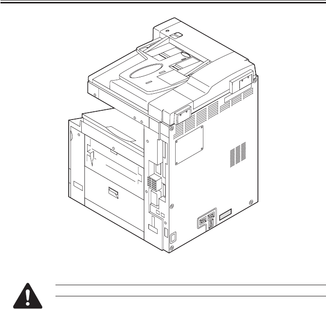
COPYRIGHT
©
2001 CANON INC. 2000 2000 2000 2000 CANON iR2200/iR2800/iR3300 REV.0 MAR. 2001
CHAPTER 1 INTRODUCTION
1-2 P
F01-102-01 CDRH Label
The description may vary from model to model.
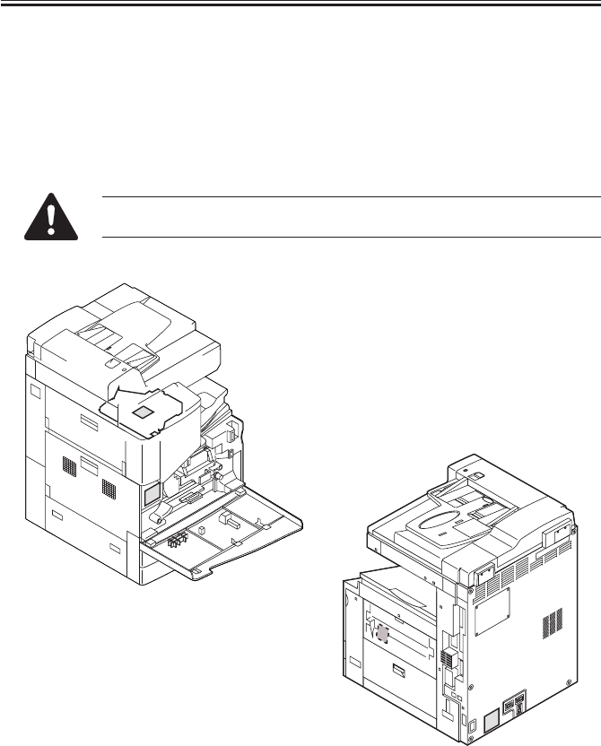
COPYRIGHT
©
2001 CANON INC. 2000 2000 2000 2000 CANON iR2200/iR2800/iR3300 REV.0 MAR. 2001
CHAPTER 1 INTRODUCTION
1-3 P
1.3 Handling the Laser System
You must take extra care when servicing the area around the machine’s laser system, as by
not bringing a high-reflectance screwdriver into the laser path.
Take such precautions as removing the watch and rings before starting the work (to pre-
vent reflection of laser light to the eye).
The machine’s laser light is red, and covers that can reflect laser light are identified by the
following label. Take full care whenever servicing areas of the machine behind these covers.
This label is attached to all covers inside the machine where hazards from
laser light exist.
F01-103-01 Laser Warning Label

COPYRIGHT
©
2001 CANON INC. 2000 2000 2000 2000 CANON iR2200/iR2800/iR3300 REV.0 MAR. 2001
CHAPTER 1 INTRODUCTION
1-4 P
1.4 Safety of Toner
The machine’s toner is a non-toxic product consisting of plastic, iron, and small amounts
of dyes.
If your skin or clothes have come into contact with toner, try removing as much of it as
possible with dry paper tissues, and wash off with water. (Do not use warm water, as it
would turn the toner jelly-like and become fused with the fibers of the fabric.)
In addition, avoid bringing toner into contact with plastic material, as it tends to dissolve
easily.
Do not throw toner into fire to avoid explosion.
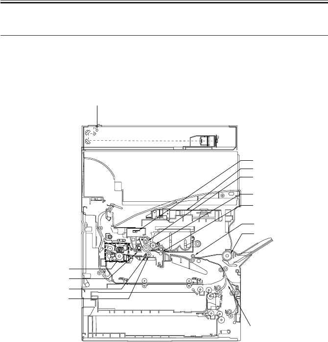
COPYRIGHT
©
2001 CANON INC. 2000 2000 2000 2000 CANON iR2200/iR2800/iR3300 REV.0 MAR. 2001
CHAPTER 1 INTRODUCTION
1-5 P
2 Image Formation System
2.1 Outline
The machine uses an indirect-electro photographic method, and has the following con-
struction:
F01-201-01 Construction of the Machine
[7] Registration roller
[8] Pickup (manual feed tray)
[9] Pickup (deck/cassette)
[10]Transfer roller
[11]Static eliminator
[12]Cleaner assembly (drum unit)
[13]Fixing assembly
[1] Scanning lamp
[2] Pre-exposure lamp
[3] Laser scanner unit
[4] Primary charging roller
[5] Developing cylinder
[6] Pre-transfer roller
[1]
[4]
[5]
[8]
[9]
[7]
[6]
[3]
[2]
[13]
[12]
[11]
[10]
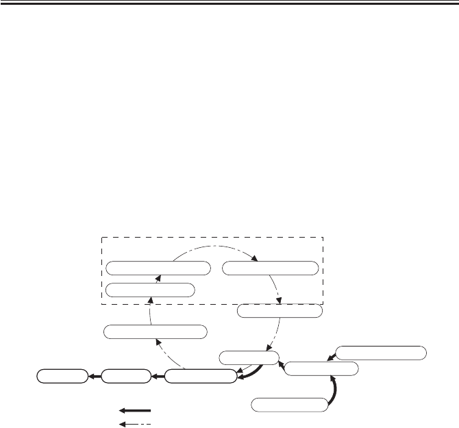
COPYRIGHT
©
2001 CANON INC. 2000 2000 2000 2000 CANON iR2200/iR2800/iR3300 REV.0 MAR. 2001
CHAPTER 1 INTRODUCTION
1-6 P
The machine’s image formation process consists of the following eight steps:
Step 1 Pre-exposure
Step 2 Primary charging (positive DC)
Step 3 Laser exposure*
Step 4 Development (AC + positive DC)
Step 5 Transfer (negative DC)
Step 6 Separation (AC + positive DC)
Step 7 Fixing
Step 8 Drum cleaning
*Deposits toner on the VD; the laser is also used for blank exposure.
F01-201-02
8. Drum cleaning
1. Pre-exposure
2. Primary charging 3. Laser exposure
4. Development
5. Transfer
6. Separation
7. Fixing
Delivery
Deck/cassette
Registration
Manual feed tray
flow of paper.
direction of drum rotation.
Latent Static Image Formation Block

COPYRIGHT
©
2001 CANON INC. 2000 2000 2000 2000 CANON iR2200/iR2800/iR3300 REV.0 MAR. 2001
CHAPTER 2
SEQUENCE OF OPERATIONS
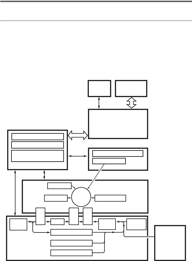
COPYRIGHT
©
2001 CANON INC. 2000 2000 2000 2000 CANON iR2200/iR2800/iR3300 REV.0 MAR. 2001
CHAPTER 2 SEQUENCE OF OPERATIONS
2-1 P
1 Basic Operations
1.1 Functional Construction
The printer unit can broadly be divided into the following four functional blocks
(shaded):
• Control system
• Laser exposure system
• Image formation system
• Pickup/feed system
F02-101-01
Control
panel
DC controller PCB
Main power supply PCB
Conposit power supply
PCB
Main controller PCB
Laser driver PCB
Laser scanner
Charging
Development
Transfer
Pickup
control Multi-
feeder
Cleaning
Duplexing assembly
Cassette 1
Delivery
tray
Feeding
Separation
Fixing
Photo-
sensitive
drum
Cassette 2
Laser
Exposure Block
Pickup/Feeding Block
Image Formation Block
Control Block
Reader
controller
PCB
Side paper
deck
(accessory)
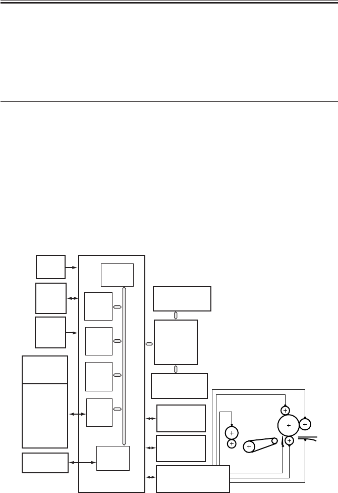
COPYRIGHT
©
2001 CANON INC. 2000 2000 2000 2000 CANON iR2200/iR2800/iR3300 REV.0 MAR. 2001
CHAPTER 2 SEQUENCE OF OPERATIONS
2-2 P
1.2 Outline for the Electrical Circuitry
1.2.1 Outline
The major electrical mechanisms of the printer unit are controlled by the CPU on the DC
controller PCB. The functions of the major elements are as follows:
1.2.2 DC Controller PCB
Name Description
CPU • Controls jobs, Controls operational state, Controls fixing temperature, Controls
high voltage.
• Controls toner supply, Controls paper feed, Controls print sequence, Controls out-
put
• Controls motors, Controls accessories
• Controls communication with the controller block, Controls service mode
RAM • Stores service mode data
• Stores user mode data
• Stores control data
DIMM ROM • Flash memory for storage of the control programs
ROM • Mask ROM for control programs (for figure support)
T02-102-01 Control Functions
F02-102-01
CPU
(IC300)
SRAM
(IC302)
IPC
(IC309)
ROM
(IC301)
PIO
(IC303)
GATE
ARRAY
(IC334)
DC controller
PCB
Composite power
supply PCB
Drum
sensor
PCB
BD
PCB
Reader
controller PCB
Main power
supply PCB
DC loads
• Clutch
• Solenoid
• Motor
• Sensor
• Fan
• Etc.
Pickup
PCB
Laser
drive
PCB
Finisher
(accessory)
Accessories
power
supply PCB
Control
panel
Main
controller PCB
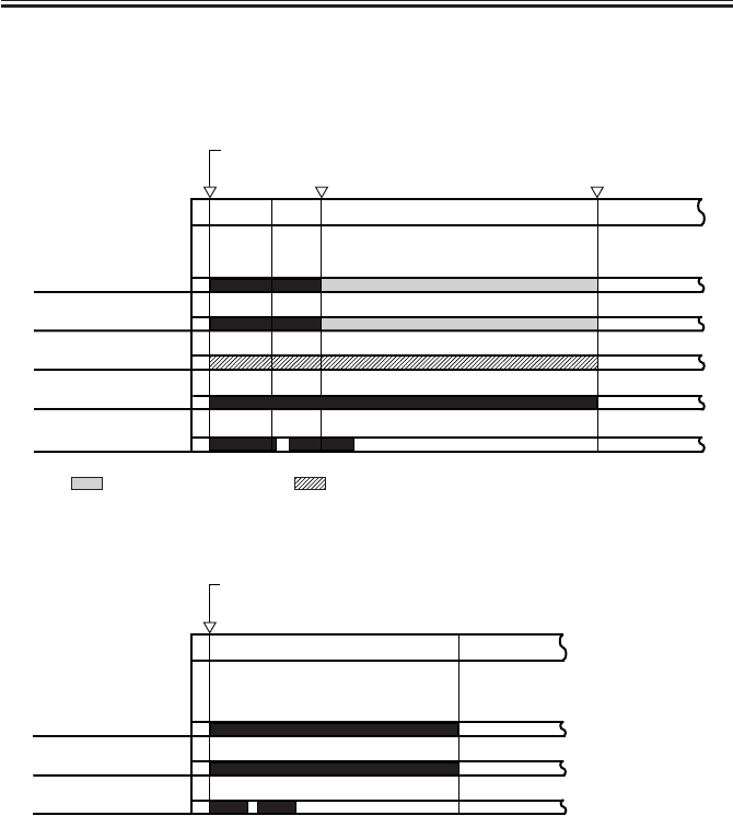
COPYRIGHT
©
2001 CANON INC. 2000 2000 2000 2000 CANON iR2200/iR2800/iR3300 REV.0 MAR. 2001
CHAPTER 2 SEQUENCE OF OPERATIONS
2-3 P
1.3 Basic Sequence of Operations
1.3.1 Basic Sequence of Operations at Power-On
• If the reading of the main thermistor (TH1) is less than 100°C
• If the reading of the main thermistor (TH1) is 100°C or more.
*1: The scanning lamp goes OFF at the end of shading.
T02-103-01
Power switch ON
Scanning lamp
(LAMP1)
Fixing main heater
(H1)
Fixing sub heater
(H2)
Main motor (M1)
Fixing motor (M4)
STBY
WUP1
WUP2
WUP3
200˚C 200˚C
: controlled to 200˚C. : low-speed drive (1/4 of constant speed).
*1
Power switch ON
Scanning lamp
(LAMP1)
Main motor (M1)
Fixing moter (M4)
STBYINTR
*1

COPYRIGHT
©
2001 CANON INC. 2000 2000 2000 2000 CANON iR2200/iR2800/iR3300 REV.0 MAR. 2001
CHAPTER 2 SEQUENCE OF OPERATIONS
2-4 P
Interval Description
WUP1 (warm-up 1) Supplies power to the heater at 65% for a specific period of time (400
msec).
WUP2 (warm-up 2) Controls by switching with in the range between 65% and 100% every 300
msec until the reading is 200°C. (The rate is determined in relation to the
increase in temperature for each specific period of time.)
WUP3 (warm-up 3) Executes temperature adjustment to 200°C for a specific period of time (10
sec).
INTR (jam check) Makes a power-on jam check when the power is turned on.
STBY (standby) Keeps the machine at rest from when WUP3 ends to the Start key is pressed
or until the power switch is turned off.
T02-103-01
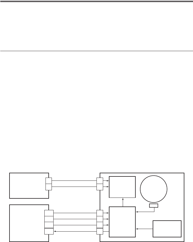
COPYRIGHT
©
2001 CANON INC. 2000 2000 2000 2000 CANON iR2200/iR2800/iR3300 REV.0 MAR. 2001
CHAPTER 2 SEQUENCE OF OPERATIONS
2-5 P
1.4 Controlling the Main Motor (M2)
1.4.1 Outline
The functions of the main motor control circuit are as shown in T02-104-01; for a block
diagram of the circuit, see F02-104-01.
Item Description
Power supply 24 V from the DC power supply PCB.
Drive signal Signal (MM_ON) from the DC controller PCB.
Operation/drive assembly Waste toner feed screw
Cleaner assembly
Registration roller
Manual pickup assembly
Left deck feeding roller 2
Developing unit
Control ON/OFF control
Constant speed control
Error detection ‘E010’ (error code)
T02-104-01
[1] When the main motor drive signal (MM_ON) goes ‘1’, the main motor starts to rotate.
[2] When the main motor starts to rotate, the clock pulse signal (MM_LOCK=1) is gener-
ated. If the DC controller PCB detects a fault in the clock pulse signal, the machine will
indicate ‘E010’ in its control panel.
F02-104-01 Control Circuit Block Diagram
Drive circuit
Control
circuit Reference
signal gene-
ration circuit
Clock pulse
generation
circuit
J3086
J3088
J308
J202
DC controller
PCB
Main power
supply PCB
1
2
1
2
3
4
1
2
A10
A9
A8
A7
24VU1-SW
MM_ON
MM_LOCK
0VU1
GND
+5V
Main motor
(M1)
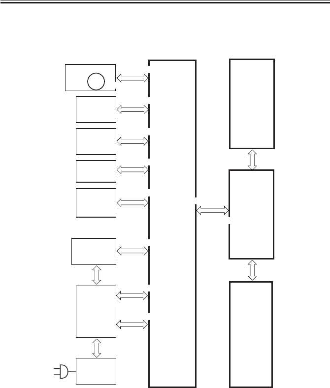
COPYRIGHT
©
2001 CANON INC. 2000 2000 2000 2000 CANON iR2200/iR2800/iR3300 REV.0 MAR. 2001
CHAPTER 2 SEQUENCE OF OPERATIONS
2-6 P
1.5 Inputs to and Outputs from the Major PCBs
1.5.1 Wiring Diagram of the Major PCBs
F02-105-01
Main
controller
PCB
DC
controller
PCB
BD
PCB
Feed
PCB
Switch
PCB
Drum
sensor
PCB
Conposit
power supply
PCB
Reader
controller
PCB
Laser scanner
motor
J312
Laser
driver
PCB
J307/310
J301
J302
Main
power
supply
PCB
J300
J6
J111
J201
J311
J1015
J316
J801
J1012
J312
J409
J1014
J3129
Control
panel
CPU PCB
M10
J3114
J1601
J136
J204
J308
J205
J500/501
J3128

COPYRIGHT
©
2001 CANON INC. 2000 2000 2000 2000 CANON iR2200/iR2800/iR3300 REV.0 MAR. 2001
CHAPTER 3
LASER EXPOSURE SYSTEM

COPYRIGHT
©
2001 CANON INC. 2000 2000 2000 2000 CANON iR2200/iR2800/iR3300 REV.0 MAR. 2001
CHAPTER 3 LASER EXPOSURE SYSTEM
3-1 P
1 Outline of Operations
1.1 Outline
Part 2>Chapter 4>1.1 “Outline of Laser Exposure System”
The reader controller PCB serves to read image signals from the CCD and send image
signals to the main controller assembly. The video signals from the main controller assem-
bly are converted by the DC controller PCB into laser drive signals, and are turned into laser
intensity signals to suit signal levels by the laser driver PCB.
The laser intensity signals are used to cause the laser unit to generate a laser beam, which
is directed to the photosensitive drum for the formation of latent static images.
Item Description
Laser intensity control Laser power auto control (APC control)
Laser scanning By semiconductor laser
Synchronization control Main scanning direction: control by BD signal
Sub scanning direction: control by image leading edge signal
Laser scanner motor control Constant speed rotation control
T03-101-01
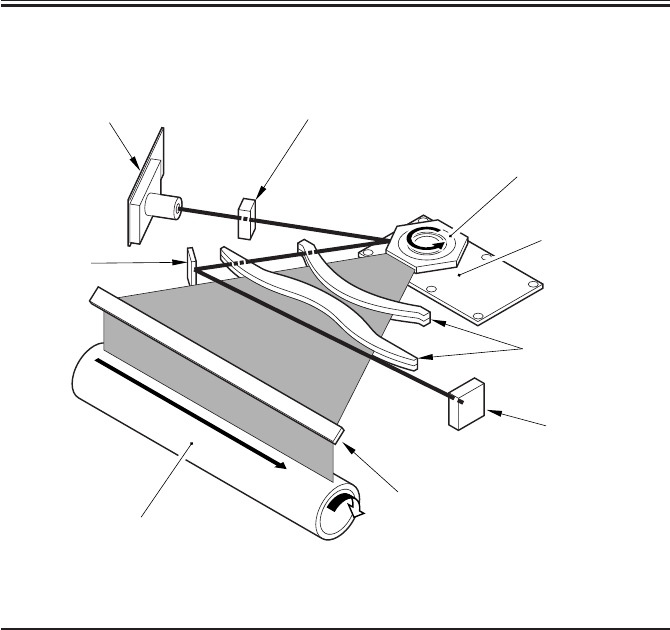
COPYRIGHT
©
2001 CANON INC. 2000 2000 2000 2000 CANON iR2200/iR2800/iR3300 REV.0 MAR. 2001
CHAPTER 3 LASER EXPOSURE SYSTEM
3-2 P
F03-101-01 shows the major components for the laser exposure system; the machine’s la-
ser scanning is performed by means of a 6-facet polygon mirror and a single-beam laser unit:
F03-101-01
Component Description
Laser semiconductor Infrared laser light (785 nm), single-beam
Laser scanner motor (M10) DC brush-less motor, constant speed control
Polygon mirror 6-faceted
BD mirror/BD PCB Laser beam detection
Laser driver PCB Laser activation control
DC controller PCB Laser scanner motor rotation control
T03-101-02
Cylindrical lens
Laser scanner motor
Polygon mirror
(6-faceted)
Collimating lens
BD PCB
Photosensitive drum
Laser mirror
BD mirror
Laser unit
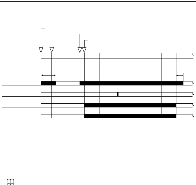
COPYRIGHT
©
2001 CANON INC. 2000 2000 2000 2000 CANON iR2200/iR2800/iR3300 REV.0 MAR. 2001
CHAPTER 3 LASER EXPOSURE SYSTEM
3-3 P
1.2 Sequence of Operations (laser exposure system)
F03-102-01
2 Generating Sync Signals
2.1 Outline
Part 2>Chapter 4>2 “Generating the BD Signal”
The BD signal used to synchronize the video signals in laser scanning direction is gener-
ated by the BD PCB with reference to the laser beam reflected by the BD mirror mounted in
the path of the laser beam.
The edge of paper re-picked in double-sided mode is detected by the horizontal registra-
tion sensor to measure the displacement to the rear/front. Based on the measurement, the
timing of laser activation is changed with reference to the BD signal so that the image will
be placed at a specific position on the paper without fail.
Main power switch ON/sleep mode OFF
Original set/ADF opened/key operated
Start key ON
180˚C
8 sec
Image leading
edge signal
Laser
PRINT
INTR
AINTR
LSTR STBY
STBY
BD signal
Laser scanner
motor
*: If silent mode (in user mode) is selected, the motor stops after a
specific period of time.
*
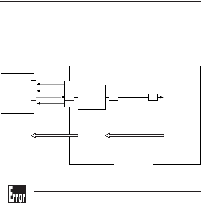
COPYRIGHT
©
2001 CANON INC. 2000 2000 2000 2000 CANON iR2200/iR2800/iR3300 REV.0 MAR. 2001
CHAPTER 3 LASER EXPOSURE SYSTEM
3-4 P
2.2 Flow of Sync signals
[1] The BD signal goes ‘0’ when laser light is detected.
[2] The phase is matched with the phase of the printer, and a sync signal is generated.
[3] Based on the printer sync signal, image data is read from the image memory.
[4] Video signal
[5] The 2-pixel parallel signal is converted into a single-pixel serial signal.
[6] The laser drive signal is used to drive the laser unit to suit the video signal.
F03-202-01
E100
Indicates that the BD signal cannot be detected within a specific period of
time after the laser has been turned on.
BD PCB
DC controller
PCB
[1]
J3129 J312
J1015
J316
J316
J307
J500 J1015
GND
GND
5V
[4]
[6]
[3]
1
2
3
4
A18
B14
B13
B12
B11
Laser driver
PCB
Controller assembly
Sync signal
generation
[2]
Memory
control
A18
Parallel/
serial
conversion
[5]

COPYRIGHT
©
2001 CANON INC. 2000 2000 2000 2000 CANON iR2200/iR2800/iR3300 REV.0 MAR. 2001
CHAPTER 3 LASER EXPOSURE SYSTEM
3-5 P
3 Laser Driver Circuit
3.1 Controlling the Laser Unit
The laser driver circuit is used to drive the semiconductor laser according to the laser
drive signal from the DC controller PCB.
The laser driver circuit performs the following:
1. Turning on/off the laser.
2. Controlling the light intensity of the laser (APC control).
The signals have the following meanings and functions:
[1] Laser drive signal; used to drive the semiconductor laser.
[2] Sample laser activation signal; used to turn on the laser for intensity sampling (the result
is used for activation for imaging).
[3] Laser enable signal; goes ‘0’ when the laser is ready after the Start key is pressed.
[4] Image leading edge signal; used to start laser writing when paper reaches the image
leading edge sensor (PS12) mounted in front of the photosensitive drum.
[5] Used to monitor the laser intensity when the laser is turned on for sampling, and feeds
back the level appropriate to the intensity to the laser driver circuit.
[6] Used to control the output so that the feedback level and the reference level from the DC
controller will be identical.
[7] Laser intensity reference signal; used as the laser activation reference level determined
by the DC controller.
[8] Horizontal registration paper detection signal; used to adjust the image position by
changing the timing of laser activation with reference to the result of detection of the
edge of paper re-picked in double-sided mode by the horizontal registration sensor
(PS11).
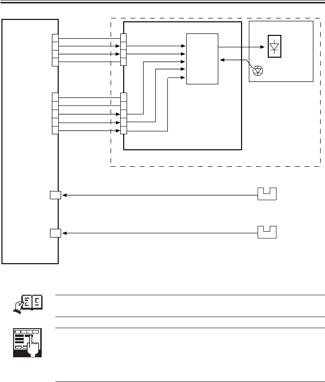
COPYRIGHT
©
2001 CANON INC. 2000 2000 2000 2000 CANON iR2200/iR2800/iR3300 REV.0 MAR. 2001
CHAPTER 3 LASER EXPOSURE SYSTEM
3-6 P
F03-301-01
REF.
The laser power of the laser unit is adjusted at the factory, and it must not
be adjusted in the field.
ADJUST>LASER>PVE-OFST
Use it to adjust the position of laser illumination.
ADJUST>LASER>LA-OFF
Use it to adjust the timing of laser trailing edge de-activation for non-de-
fault size papers.
J307
J310
DATA(+) [1]
DAOUT [7]
LDE* [3]
S/H [2]
DATA(-) [1]
GND
Laser driver PCB
DC controller
PCB
J500
[6]
J501
Laser assembly
Laser
Intensity
monitor [5]
Laser
drive
circuit
3
2
1
5
4
3
1
2
1
2
3
5
4
4
3
2
1
1
2
3
4
GND
GND
+5V
J312INT_TOPO_PD [4]
A14
Image leading edge
sensor
(PS12)
J304 Y_REG_PD [8]
A8
Horizontal registration
paper sensor
(PS11)
Laser unit

COPYRIGHT
©
2001 CANON INC. 2000 2000 2000 2000 CANON iR2200/iR2800/iR3300 REV.0 MAR. 2001
CHAPTER 3 LASER EXPOSURE SYSTEM
3-7 P
4 Controlling the Laser Scanner Motor
4.1 Outline
Part 2> Chapter 4> 4.1 “Outline”
The following items are related to laser scanner motor control:
[1] Laser scanner motor drive signal; when ‘1’, the laser scanner motor goes ON (turning
on/off the motor).
[2] Laser scanner motor ready signal; when ‘0’, the laser scanner motor rotates at a specific
speed.
F03-401-01
E110
Indicates the presence of an error in the laser scanner motor.
J312
J204
J3128
+24V
GND
[2]
[1]
Laser scanner
motor
Laser scanner motor unit
DC controller
PCB 2
3
4
1
2
1
B10
B9
Speed
control
circuit
Reference
pulse
generation
circuit
Motor
driver
Main power
supply PCB
M10

COPYRIGHT
©
2001 CANON INC. 2000 2000 2000 2000 CANON iR2200/iR2800/iR3300 REV.0 MAR. 2001
CHAPTER 3 LASER EXPOSURE SYSTEM
3-8 P
5 Disassembly and Assembly
The discussions that follow cover the machine’s mechanical characteristics and how to
disassemble/assemble the machine. Keep the following in mind whenever you work with the
machine:
1. The power plug must remain disconnected for safety when disassembling/assembling
the machine.
2. Unless otherwise noted, the machine may be assembled by reversing the steps used to
disassemble it.
3. The screws must be identified by type (length, diameter) and location.
4. The mounting screws used for the grounding wire and the varistors come with a washer,
which must not be left out when assembling the machine.
5. As a rule, the machine must not be operated with any of its parts removed.
6. Leakage of laser light must be avoided, as it can adversely affect the human body. Do
not disassemble parts not discussed herein or remove any paint-locked screws.
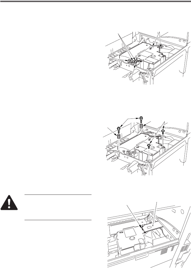
COPYRIGHT
©
2001 CANON INC. 2000 2000 2000 2000 CANON iR2200/iR2800/iR3300 REV.0 MAR. 2001
CHAPTER 3 LASER EXPOSURE SYSTEM
3-9 P
5.1 Laser Scanner Assembly
5.1.1 Removing the Laser Unit
1) Remove the delivery tray. (p. 7-13P)
2) Open the harness guide [1], and discon-
nect the two connectors [2].
3) Disconnect the connector [3] of the BD
PCB and the two connectors [4] of the
laser PCB.
F03-501-01
4) Remove the two springs [1] and two
stepped screws [2] from the left, and re-
move the two screws equipped with a
washer from the right; then, detach the
laser unit.
F03-501-02
When mounting the Finisher-J1,
attach the protective sheet [2] by
aligning it against the press line
[1] of the laser unit.
F03-501-03
[4]
[1]
[3]
[2]
[1]
[1]
[3]
[2]
[2]
[1]

COPYRIGHT
©
2001 CANON INC. 2000 2000 2000 2000 CANON iR2200/iR2800/iR3300 REV.0 MAR. 2001
CHAPTER 4
IMAGE FORMATION SYSTEM

COPYRIGHT
©
2001 CANON INC. 2000 2000 2000 2000 CANON iR2200/iR2800/iR3300 REV.0 MAR. 2001
CHAPTER 4 IMAGE FORMATION SYSTEM
4-1 P
1 Outline of Processes
1.1 Outline
T04-101-01 shows the functions of and the methods used in the image formation system:
Item Description
Photosensitive drum OPC (30-mm dia.)
drum cleaning cleaning blade
Developing assembly Developing cylinder (20-mm dia.)
Development method:dry, 1-component, toner projection
Toner:magnetic, negative
Pre-exposure (LAMP2) Fuse lamp (8 pc.)
ON/OFF control (activated in sync with main motor)
Drum sensor (U701) Primary charging roller DC bias corrected to temperature around
photosensitive drum
Environment sensor (S3) Primary charging roller AC bias corrected to suit humidity reading
Primary charging roller auto Pad push-on type
cleaning
Primary charging roller bias DC constant voltage control (-500 to -850 V)
control AC constant current control (2000 to 2300 µA; about 1800 Hz)
Developing bias control DC constant voltage control (0 to -650 V)
AC constant voltage control (810 Vp-p; about 1800 Hz)
Transfer charging roller bias Transfer bias:DC constant current control (switching
control among +15 µA, +10 µA, +7 µA) + DC constant voltage
control (up to 7 kVmax)
Cleaning bias: DC constant voltage control (-2.6 kV)
Transfer guide bias control DC constant voltage (-600 v)
Separation static eliminating DC constant voltage (switching between -2.3 KV and -3.0 KV)
bias control
T04-101-01
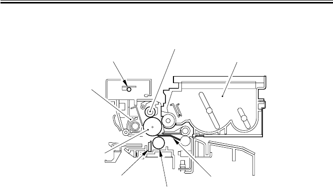
COPYRIGHT
©
2001 CANON INC. 2000 2000 2000 2000 CANON iR2200/iR2800/iR3300 REV.0 MAR. 2001
CHAPTER 4 IMAGE FORMATION SYSTEM
4-2 P
F04-101-01 shows the major components of the image formation system:
F04-101-01
Developing assembly
Transfer guide
Transfer charging roller
Separation static eliminator
Cleaner unit
Pre-exposure lamp
Primary charging roller
Photosensitive
drum
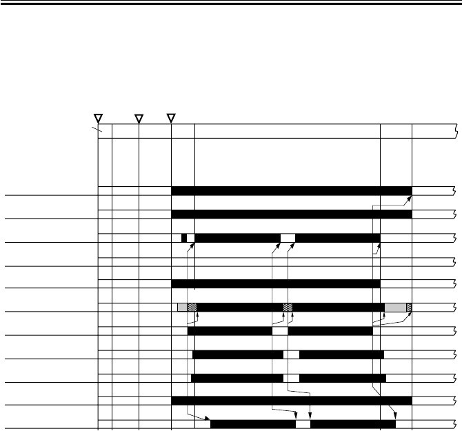
COPYRIGHT
©
2001 CANON INC. 2000 2000 2000 2000 CANON iR2200/iR2800/iR3300 REV.0 MAR. 2001
CHAPTER 4 IMAGE FORMATION SYSTEM
4-3 P
1.2 Basic Sequence of Operations (image formation system)
• 1 Original, 2 Prints
F04-102-01
Transfer charging
bias
Laser activation
Pre-exposure
lamp (LAMP2)
Main motor (M1)
Image leading
edge sensor (S12)
Developing bias
(AC)
Primary charging
bias (AC)
Primary charging
bias (DC)
Developing bias
(DC)
Transfer guide
bias
Separation static
eliminating bias
Main power
supply switch ON
Control panel
power switch
ON Start key ON
PRINT LSTR
STBY
SLEEP
STBY
INRT
AINRT
[1] [2] [2] [1]
[1] transfer charging cleaning bias
[2] transfer sheet-to-sheet interval bias
[3] transfer charging reference bias(each 1000sheets, cumulative)
[3]

COPYRIGHT
©
2001 CANON INC. 2000 2000 2000 2000 CANON iR2200/iR2800/iR3300 REV.0 MAR. 2001
CHAPTER 4 IMAGE FORMATION SYSTEM
4-4 P
2 Controlling the Primary Charging Roller Bias
2.1 Outline
Part 2>Chapter 5>4.4 “Controlling the Primary Charging Roller Bias”
The machine’s primary charging is a direct charging method that uses a charging roller. In
addition to a DC bias, the charging roller is subjected to an AC bias to ensure stable charg-
ing.
The following items relate to the control of primary charging:
[1] Turning on/off the bias.
[2] Controlling the DC bias to a specific level of voltage.
[3] Controlling the AC bias to a specific level of current.
[4] Controlling the photosensitive drum resistance detection mechanism (APVC control).
[5] Controlling the AC bias based on the readings of the environment sensor (humidity) and
the soft counters.
[6] Controlling the DC bias based on the reading of the drum sensor (temperature).
F04-201-01
Memo
The primary charging output enable signal is used as the AC pulse ON sig-
nal when the developing bias is being controlled.
DC controller PCB
Primary charging
output enable
signal
DC bias
output
control signal DC bias
output
AC bias
output
DC bias
output ON
signal
AC bias output
control signal
J301
-B4 J136
-B9
J135
J301
-A3
-A1
J136
-A10
-A12
24 VDC input from
main power supply
Composite power supply PCB
PW-CPU
Transformer
drive signal
Voltage level
J130-4
Transformer
drive signal
Photosensitive
drum
Serial communication
Print/standby mode signal
AC bias level signal
DC bias level signal
APVC measurement data
Primary AC
charging high-
voltage trans
former
Primary DC
charging high-
voltage
transformer
(T502) Primary
charging roller
Drive
control Current
detection
Output
control
Current
control
Voltage
detection
Current level
(APVC measure-
ment)
+24V
Drum sensor
(temperature)
Environment
sensor
(humidity)
Measurement result
Measurement result
J311-A2
J302-B14

COPYRIGHT
©
2001 CANON INC. 2000 2000 2000 2000 CANON iR2200/iR2800/iR3300 REV.0 MAR. 2001
CHAPTER 4 IMAGE FORMATION SYSTEM
4-5 P
2.2 Turning On/Off the Bias
The primary charging roller bias is turned on/off as follows:
2.2.1 DC Bias
[1] When the primary charging output enable signal from the DC controller PCB goes ‘0’,
the DC bias output control signal (pulse signal) is generated.
[2] The DC bias is sent to the primary charging roller.
2.2.2 AC Bias
[1] When the primary charging output enable signal from the DC controller PCB goes ‘0’,
the AC bias output control signal is generated.
[2] The AC bias is generated to the primary charging roller.
2.3 Controlling the Current Voltage/Current to a Specific Level
The output level of the DC/AC bias applied to the primary charging roller is controlled by
the DC/AC bias output control signal from the PW-CPU.
2.3.1 Controlling the DC Bias to a Specific Level
[1] The output voltage level of the DC bias is fed back to the PW-CPU, and the DC bias
output control signal is varied as needed to suit the level when driving the transformer.
[2] The DC bias is made to assume a specific voltage level.
2.3.2 Controlling the AC Bias to a Specific Current Level
[1] The output current level of the AC bias is communicated to the drive control circuit and
is compared against the reference current level; the result is used to vary the AC bias
output control signal as needed to drive the transformer.
[2] The AC bias is made to assume a specific current level.
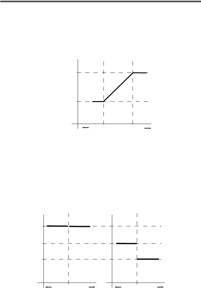
COPYRIGHT
©
2001 CANON INC. 2000 2000 2000 2000 CANON iR2200/iR2800/iR3300 REV.0 MAR. 2001
CHAPTER 4 IMAGE FORMATION SYSTEM
4-6 P
2.4 Temperature Correction of the DC Bias
When the temperature inside the machine increases, the resistance of the photosensitive
drum will decrease, thereby lowering the charging characteristics. To ensure a stable poten-
tial level, the drum sensor (U701) mounted to the rear side plate is used to check the tem-
perature inside the machine; when the temperature increases, the absolute value of the DC
bias level is increased.
F04-204-01
2.5 Humidity Correction of the AC Bias
The current level of the AC bias needs to be kept on the higher side to prevent uneven
charging because of a lower changing efficiency occurring in a low-humidity environment.
The AC bias, therefore, is varied as shown in F04-205-01 to suit the readings of the environ-
ment sensor (humidity). When the resistance of the drum surface decreases because of ad-
vancing wear, the current level is decreased to facilitate the flow of current.
F04-205-01
Primary DC bias
-750V
-800V
Machine inside temperature
High
Low
(reference
value)
23˚C 40˚C
Primary AC bias
2150µA
2000µA
2300µA
Humidity High
Low
Counter reading: 0 to 10,000 sheets Counter reading: 10,001 or higher
35% Humidity High
Low 35%

COPYRIGHT
©
2001 CANON INC. 2000 2000 2000 2000 CANON iR2200/iR2800/iR3300 REV.0 MAR. 2001
CHAPTER 4 IMAGE FORMATION SYSTEM
4-7 P
2.6 Controlling the Detection of the Photosensitive Drum Re-
sistance (APVC control)
The primary charging efficiency changes because of changes in the site environment (tem-
perature, humidity), deterioration of the charging roller, and wear of the photosensitive
drum. A reference voltage is applied to the charging roller at time of last rotation every 500
prints (cumulative) or when the following service mode is executed:
COPIER>FUNCTION>DPC>D-GAMMA, and the level of output current at the time is
measured and corrected.
[1] When the main power switch is turned on, the reference voltage is applied to the charg-
ing roller, and the output is measured as the current level for use as feedback to the PW-
CPU.
[2] The photosensitive drum is charged (primary charging) using the voltage level deter-
mined by the PW-CPU.
If you have replaced the drum unit with a new one, be sure to execute the
following service mode: COPIER>FUNCTION>DPC>D-GAMMA.

COPYRIGHT
©
2001 CANON INC. 2000 2000 2000 2000 CANON iR2200/iR2800/iR3300 REV.0 MAR. 2001
CHAPTER 4 IMAGE FORMATION SYSTEM
4-8 P
E064
Indicates the presence of a high-voltage (primary charging, transfer charg-
ing, developing) output fault.
COPIER>DISPLAY>HV-STS>PRIMARY
Use it to indicate the current level of primary charging.
COPIER>ADJUST>HV-PRI>P-DC
Use it to enter the adjustment value of the primary charging DC component
for the image area.
COPIER>ADJUST>HV-PRI>P-AC
Use it to enter the adjustment value of the primary charging AC component
for the image area.
COPIER>ADJUST>HV-PRI>AGS-GAIN
Use it to enter the gain adjustment value of the application voltage level
correction for the primary charging bias.
COPIER>ADJUST>HV-PRI>AGS-OFST
Use it to enter the offset adjustment value of the application voltage level
correction for the primary charging bias.
COPIER>ADJUST>HV-PRI>OFST1-DC
Use it to enter the adjustment value of offset 1 for the primary charging DC
component.
COPIER>ADJUST>HV-PRI>OFST1-AC
Use it to enter the adjustment value of offset 1 for the primary charging AC
component.
COPIER>ADJUST>HV-PRI>P-AC2
Use it to enter the adjustment value of primary charging AC component 2 of
the image area.
COPIER>ADJUST>HV-PRI>P-AC3
Use it to enter the adjustment value of primary charging AC component for
the image area.
COPIER>FUNCTION>DPC>D-GAMMA
Use it to force photosensitive drum resistance measurement control
(APVC).
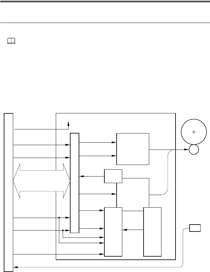
COPYRIGHT
©
2001 CANON INC. 2000 2000 2000 2000 CANON iR2200/iR2800/iR3300 REV.0 MAR. 2001
CHAPTER 4 IMAGE FORMATION SYSTEM
4-9 P
3 Controlling the Transfer Charging Roller Bias
3.1 Outline
Part 2>Chapter 5>7.8.3 “Controlling the Transfer Roller Charging”
The machine’s transfer charging is a direct charging method that uses a transfer charging
roller. A DC bias is applied to the transfer charging roller.
The following relate to the transfer charging system:
[1] Turning on/off the bias.
[2] Controlling the DC bias to a specific voltage/current level.
[3] Controlling the detection of transfer charging roller resistance (ATVC control)
[4] Controlling the output by operation mode
[5] Controlling the output by the environment sensor (humidity)
F04-301-01
DC controller PCB
Transfer
charging
output enable
signal Cleaning
bias out
Cleaning bias output
ON signal
Transfer output
mode signal 4
Transfer bias output
ON signal
Transfer bias
output control
signal
J301
-B9 J136
-B4
J135
-B8 -B5
J301
-A3
-A1
J136
-A10
-A12
24 VDC input from
main power supply
Composite power supply PCB
PW-CPU
Transformer drive
signal
T133
-B5 -B8
-B6 -B7
-B7 -B6
Transformer drive
signal
Photosensitive
drum
Transfer bias
high-voltage
transformer
(T133)
Transfer cleaning
bias high-voltage
transformer
(T506)
Transfer
bias
output
Transfer
charging roller
Voltage
detection
Voltage level
(ATVC measurement result)
+24V
Environment
sensor
(humidity)
Measurement resultJ302-B14
Serial
communication
Print/standby mode signal
Transfer bias output data
ATVC measurement data
Drive
control
Current
detection
Current
level
Transfer output
mode signal 3
Transfer output
mode signal 2
Transfer output
mode signal 1
Transfer bias output
current switching signal

COPYRIGHT
©
2001 CANON INC. 2000 2000 2000 2000 CANON iR2200/iR2800/iR3300 REV.0 MAR. 2001
CHAPTER 4 IMAGE FORMATION SYSTEM
4-10 P
3.2 Turning On/Off the Bias
The transfer charging roller bias is turned on/off as follows:
[1] When the transfer charging output enable signal from the DC controller PCB goes ‘0’,
the transfer bias output signal (serial communication) is generated.
[2] The transfer bias output control signal (pulse) is generated, and the DC bias is sent to
the transfer charging roller.
3.3 Controlling the Detection of the Transfer Charging Roller
Resistance (ATVC control)
The transfer charging efficiency changes because of changes in humidity and deteriora-
tion in the transfer charging roller. The reference current is applied to the transfer charging
roller during initial multiple rotation after the main power switch is turned on, and the re-
sulting output voltage is measured for correction.
[1] The reference current is applied to the transfer charging roller, and the output is checked
as a voltage level for use as feedback to the PW-CPU.
[2] The transfer charging mechanism operate using the voltage level determined by the PW-
CPU.
If you have replaced the transfer charging roller with a new one, be sure to
execute 'clean roller' in user mode ('adjust/clean').

COPYRIGHT
©
2001 CANON INC. 2000 2000 2000 2000 CANON iR2200/iR2800/iR3300 REV.0 MAR. 2001
CHAPTER 4 IMAGE FORMATION SYSTEM
4-11 P
3.4 Controlling the Output by Operating Mode
3.4.1 Types of Modes
The transfer charging output may be any of the following output modes, and the output is
varied to suit each mode. The switch-over among these is based on the combination of trans-
fer output mode signals from the DC controller PCB.
a. Image Transfer Bias
This bias is used to transfer toner from the photosensitive drum to paper, and is a positive
voltage.
b. Cleaning Bias
This bias is used to return toner sticking to the transfer charging roller to the photosensi-
tive drum, and applies a negative voltage.
• During initial rotation after the Start key is pressed
• During last rotation
• During initial rotation after jam removal or error resetting
• During execution of roller cleaning in user mode (‘adjust/clean’; in this case, the pri-
mary charging roller is also cleaned)
c. Reference Bias
It is an application voltage used for the transfer charging roller resistance detection con-
trol (ATVC control) mechanism. For every 1,000 prints (cumulative) or when 'roller clean' is
executed in user mode ('adjust/clean'), the voltage is applied at time of last rotation.
d. Sheet-to-Sheet Interval Bias
This bias is used in a non-image area (between sheets) in continuous print mode; the bias
level is reduced to prevent adhesion of toner to the transfer charging roller.
E064
Indicates the presence of a high-voltage (primary charging, transfer charg-
ing, development) output fault.

COPYRIGHT
©
2001 CANON INC. 2000 2000 2000 2000 CANON iR2200/iR2800/iR3300 REV.0 MAR. 2001
CHAPTER 4 IMAGE FORMATION SYSTEM
4-12 P
F04-304-01
3.4.2 Turning On/Off the Cleaning Bias
When the cleaning bias output ON signal (composite power supply PCB) goes ‘1’, the
output of the transfer cleaning bias transformer is applied to the transfer charging roller.
SLEEP
STBY INTR
AINTR PRINT LSTR STBY
Main motor (M1)
Main power
switch ON
Control panel
power switch
ON Start key ON
Image transfer
bias
Cleaning bias
Reference bias
Sheet-to-sheet
bias
*1
*1: Applied every 1,000 prints (cumulative) at time of last rotation.
COPYRIGHT
©
2001 CANON INC. 2000 2000 2000 2000 CANON iR2200/iR2800/iR3300 REV.0 MAR. 2001
CHAPTER 4 IMAGE FORMATION SYSTEM
4-13 P
3.5 Controlling the Output
The output of the DC bias applied to the transfer charging roller is controlled as follows:
The optimum transfer charging roller bias differs depending on paper size and site environ-
ment; as such, the DC controller is designed to automatically control the output level to suit
the paper size and the site environment in question.
COPIER>DISPLAY>HV-STS>TR
Use it to display the level of current for transfer charging.
COPIER>DISPLAY>HV-STS>TR-V
Use it to indicate the voltage level of the transfer charging roller resistance
detection.
COPIER>ADJUST>HV-TR>TR-N1
Use it to enter the output adjustment value for transfer charging (plain pa-
per; single-sided print or 1st side of double-sided print).
COPIER>ADJUST>HV-TR>TR-N2
Use it to enter the output adjustment value for transfer charging (plain pa-
per; 2nd side of double-sided print)
COPIER>ADJUST>HV-TR>TR-OFST
Use it to enter the offset output adjustment value for transfer charging roller
resistance detection.
COPIER>ADJUST>HV-TR>TR-SPP
Use it to enter the output adjustment value for transfer charging (special pa-
per; single-sided print and double-sided print)
COPIER>OPTION>BODY>TRANS-SW
Use it to set the transfer charging roller bias output control method for
large-size paper.
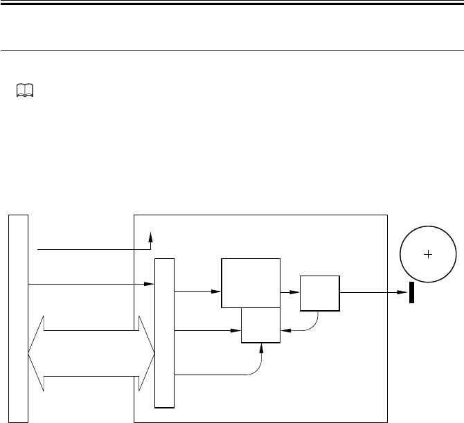
COPYRIGHT
©
2001 CANON INC. 2000 2000 2000 2000 CANON iR2200/iR2800/iR3300 REV.0 MAR. 2001
CHAPTER 4 IMAGE FORMATION SYSTEM
4-14 P
4 Controlling the Separation Static Eliminator Bias
4.1 Outline
Part 2>Chapter 5>8.3 “Static Eliminator Separation Method”
The machine uses a static eliminator for separation. A DC bias is applied to the static
eliminator; the following are items of control:
[1] Turning on/off the bias
[2] Controlling the bias to a specific voltage level
[3] Controlling the output to suit paper type and reading by the environment sensor (humid-
ity)
F04-401-01
DC controller PCB
Static
eliminator bias
enable signal
Static eliminator bias
mode signal
Static
eliminator
bias output
J301
-B3 J136
-B10
J135
J301
-A3
-A1
J136
-A10
-A12
24 VDC input from
main power supply
Composite power supply PCB
PW-CPU
Transformer
drive signal
J132
Serial communication
Print/standby mode signal
Static eliminator bias
mode signal
High-voltage
main
transformer
(T504)
Separation
static eliminator
Output
control
Voltage
detection
Voltage
level
+24V
Static
eliminator bias
output ON signal
Photosensitive
drum

COPYRIGHT
©
2001 CANON INC. 2000 2000 2000 2000 CANON iR2200/iR2800/iR3300 REV.0 MAR. 2001
CHAPTER 4 IMAGE FORMATION SYSTEM
4-15 P
4.2 Turning On/Off the Bias
The separation static eliminator bias is turned on/off as follows:
[1] When the static eliminator bias enable signal from the DC controller PCB goes ‘0’, the
static eliminator bias output ON signal is generated.
[2] A DC bias is sent to the separation static eliminator.
4.3 Controlling the Bias to a Specific Voltage Level
The bias output is fed back to the output control circuit, thereby ensuring a specific level
of voltage.
4.4 Controlling the Output by Paper Type and Environment
Sensor (humidity)
In a low-humidity environment, separation can fail when thin paper is used or when the
second side of a double-sided sheet is hadled. To ensure good separation, the voltage ap-
plied is increased between -2.3 and -3.0 KV with reference to the type of paper and the
reading of the environment sensor (humidity).
The selection of an application voltage is done in response to the static eliminator bias
mode signal (serial communication) from the DC controller PCB.
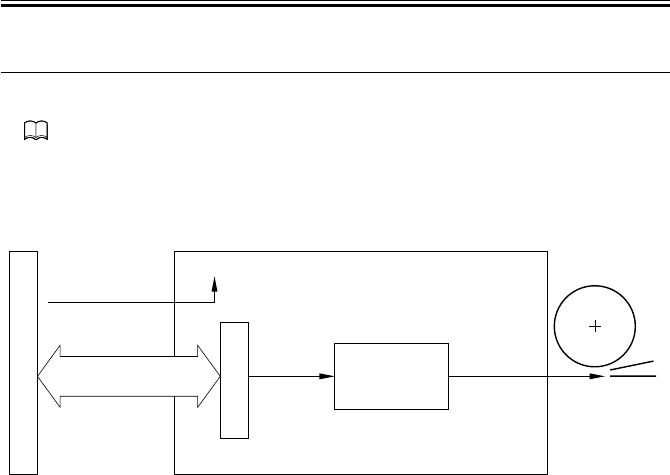
COPYRIGHT
©
2001 CANON INC. 2000 2000 2000 2000 CANON iR2200/iR2800/iR3300 REV.0 MAR. 2001
CHAPTER 4 IMAGE FORMATION SYSTEM
4-16 P
5 Controlling the Transfer Guide Bias
5.1 Transfer Guide Bias
Part 2>Chapter 5>7.2 “Transfer Guide Type”
The transfer guide bias is used to prevent adhesion of toner to the transfer guide, and is a
negative component (-600 VDC), which is of the same polarity as the toner.
The transfer guide bias is continuously applied as long as printing is under way.
F04-501-01
DC controller PCB
Transfer
guide output
J135
J301
-A3
-A1
J136
-A10
-A12
24 VDC input
from main
power supply
Composite power supply PCB
PW-CPU
Transformer
drive signal
J131-3
Photosensitive
drum
High-voltage
main transformer
(T504) Transfer
guide
+24V
Serial communication
Print/standby mode signal
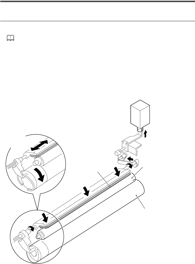
COPYRIGHT
©
2001 CANON INC. 2000 2000 2000 2000 CANON iR2200/iR2800/iR3300 REV.0 MAR. 2001
CHAPTER 4 IMAGE FORMATION SYSTEM
4-17 P
6 Primary Charging Roller Cleaning Mechanism
6.1 Outline
Part 2>Chapter 5>10.1.5 “Cleaning the Primary Charging Roller ”
The machine’s primary charging roller is cleaned by turning on the primary charging
roller cleaning solenoid (SL6) while the primary charging roller is rotating, thereby butting
the cleaning pad against the primary charging roller. At the same time, the cleaning pad is
moved back and forth in the axial direction of the primary charging roller.
Cleaning is executed under the following conditions:
• During last rotation after the cumulative count reaches 500 sheets
• During execution of roller cleaning in user mode (‘adjust/clean’; in this case, the clean-
ing bias is applied to the transfer charging roller pad for cleaning)
F04-601-01
Cleaning pad Primary charging roller
Photosensitive drum
SL6 (ON)
Back-and-forth
movement

COPYRIGHT
©
2001 CANON INC. 2000 2000 2000 2000 CANON iR2200/iR2800/iR3300 REV.0 MAR. 2001
CHAPTER 4 IMAGE FORMATION SYSTEM
4-18 P
7 Developing Assembly
7.1 Outline
The developing assembly consists of the developing cylinder, toner sensor (S1), and toner
stirring rod; its is locked manually together with the developing rail using the locking lever.
The developing cylinder and the toner stirring rod are rotated by the drive of the main mo-
tor (M1) transmitted by way of the developing clutch (CL3).
F04-701-01
J130-1
DC controller PCB
Developing bias
control signal Developing bias
Composite power
supply PCB
Main motor drive signal
J308
Toner detention signal
J302-5
J301 J136
Photosensitive
drum
Developing cylinder
Main
motor
Toner stirring rods
PW-CPU
M1 CL3
Developing
clutch
Toner sensor(S1)

COPYRIGHT
©
2001 CANON INC. 2000 2000 2000 2000 CANON iR2200/iR2800/iR3300 REV.0 MAR. 2001
CHAPTER 4 IMAGE FORMATION SYSTEM
4-19 P
7.2 Controlling the Developing Bias
7.2.1 Outline
Both DC bias and AC bias are applied to the developing cylinder. The output is controlled
by the composite power supply PCB based on the control signal from the DC controller
PCB.
The following relate to the developing bias control system:
[1] Controlling the DC developing bias to a specific voltage level
[2] Controlling the AC developing bias to a specific voltage level
F04-702-01
Memo
The AC pulse ON signal is used as the primary charging output enable sig-
nal when controlling primary charging.
DC controller PCB
DC bias
ON signal
DC bias control signal
AC pulse
ON signal
AC bias
ON signal
J301
-B1 J136
-B12
-B4 -B9
J301
-A3
-A1
J136
-A10
-A12
J301
-B2 J136
-B11
Composite power supply PCB
PW-CPU
Transformer
drive signal
High-voltage
main
transformer
(for DC)
Developing
high-voltage
transformer
(for AC)
AC bias
Voltage level
Output
control Voltage
detection
Developing
cylinder
J130-1
Transformer
drive signal
Serial
communication
DC bias level signal
Photosensitive
drum
J135
24 VDC input from
main power supply
+24V

COPYRIGHT
©
2001 CANON INC. 2000 2000 2000 2000 CANON iR2200/iR2800/iR3300 REV.0 MAR. 2001
CHAPTER 4 IMAGE FORMATION SYSTEM
4-20 P
7.2.2 Controlling the DC Developing Bias
[1] When the DC bias ON signal from the DC controller PCB goes ‘0’, the bias control sig-
nals (pulse signals) are generated by the PW-CPU of the high-vole power supply PCB.
[2] The DC bias from the high-voltage main transformer is applied to the developing cylin-
der.
[3] The output voltage level of the DC bias is fed back to the PW-CPU.
[4] The pulse width of the DC control signal is varied to suit the return voltage, thereby
maintaining the DC bias to a specific level.
7.2.3 Controlling the AC Developing Bias
[1] When the AC bias ON signal and the AC pulse ON signal from the DC controller PCB
goes ‘0’, the AC transformer is driven.
[2] An AC bias is added to the DC bias and applied to the developing cylinder.
7.2.4 Controlling the Level of the DC Developing Bias
the level of the DC developing bias is varied between image area and non-image area to
prevent stray toner inside the machine.
In memory copy mode, the laser is driven based on binary image data which lacks density
information, not enabling adjustment using a density correction curve for the density of the
image being generated. To make up for the lack, the DC developing bias is varied for den-
sity adjustment.
E064
Indicates the presence of a high-voltage (primary charging, transfer charg-
ing, development) output fault.
COPIER>ADJUST>DEVELOP>DE-DC
Use it to enter the adjustment value of the developing bias DC component
for the image area.
COPIER>ADJUST>DEVELOP>DE-OFST
Use it to enter the offset value for the developing bias DC component.
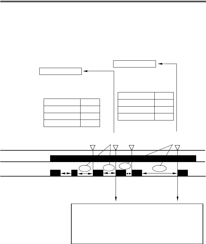
COPYRIGHT
©
2001 CANON INC. 2000 2000 2000 2000 CANON iR2200/iR2800/iR3300 REV.0 MAR. 2001
CHAPTER 4 IMAGE FORMATION SYSTEM
4-21 P
7.3 Detecting the Level of Toner
A toner sensor (S1) of a piezoelectric oscillation type is mounted inside the developing
assembly for detection of the level of toner. The DC-CPU on the DC controller PCB reads
the output of the toner sensor as long as the developing clutch (CL3) remains on; it keeps
track of the ‘0’ state of the toner sensor (most recent two readings), and indicates the Add
Toner message as needed.
F04-703-01
Developing clutch
(CL3)
Check point
Toner sensor(S1) 2 sec 4 sec 4 sec 22 sec
NG
(8 sec in total)
OK
(6 sec in total)
OK
(5 sec in total)
NG
(23 sec)
Toner absent level 1
Copying
FAX reception
FAX transmission
Printer output
enabled
enabled
enabled
enabled
toner absent level 2
The cumulative period of
absence of toner fro the
most recent two readings
is 7 sec or more,
The cumulative period of
absence of toner for the
most recent two readings
is 20 sec or more,
Copying
FAX reception
FAX output
Printer output
disabled
enabled
disabled
disabled
1 sec
When the main power switch is turned off and then on, stirring
operation is undertaken for 6 sec and is monitored; if toner is
present, stirring takes place. If no toner is detected, stirring
operator is undertaken for another 30 sec; then, stirring operation
is undertaken once again for 6 sec to check the presence of toner;
if toner is found, recovery is made. If toner is not found, the Add
Toner message will be indicated.
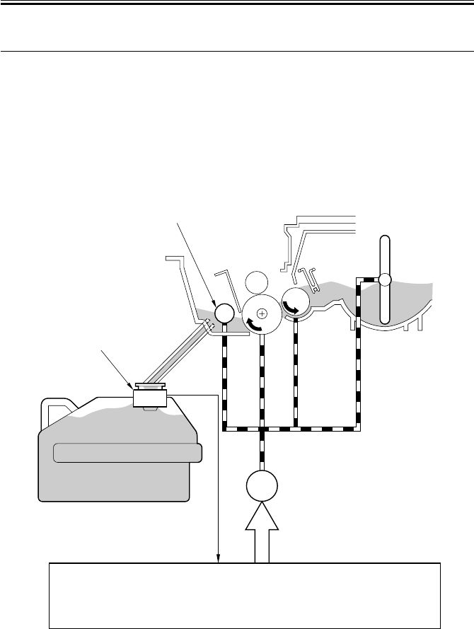
COPYRIGHT
©
2001 CANON INC. 2000 2000 2000 2000 CANON iR2200/iR2800/iR3300 REV.0 MAR. 2001
CHAPTER 4 IMAGE FORMATION SYSTEM
4-22 P
8 Drum Cleaner
8.1 Outline
The drum cleaner assembly is rotated by the drive of the main motor (M1) transmitted
through drive gears; the waste toner is colleted by the cleaning blade, and is sent to the
waste toner case using the waste toner feedscrew.
The amount of waste toner inside the waste toner case is monitored by the waste toner
case full sensor (S2); when the amount exceeds a specific level, the Waste Toner Full mes-
sage will be indicated on the control panel.
F04-801-01
M1
Waste toner case full signal
Waste toner case full
sensor (S2)
S2
Main motor
J308
J311-B9
Waste toner
feedscrew
Waste toner case
DC controller PCB
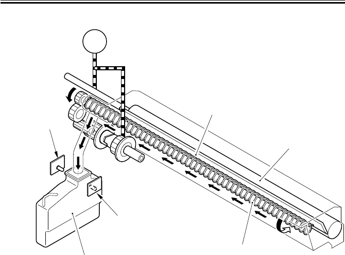
COPYRIGHT
©
2001 CANON INC. 2000 2000 2000 2000 CANON iR2200/iR2800/iR3300 REV.0 MAR. 2001
CHAPTER 4 IMAGE FORMATION SYSTEM
4-23 P
F04-801-02
M1
Main motor
Waste toner case
Waste toner case
full sensor
(S2; light-emitting)
Waste toner case
full sensor
(S2; light-receiving)
Waste toner feedscrew
Photosensitive drum
Cleaning blade
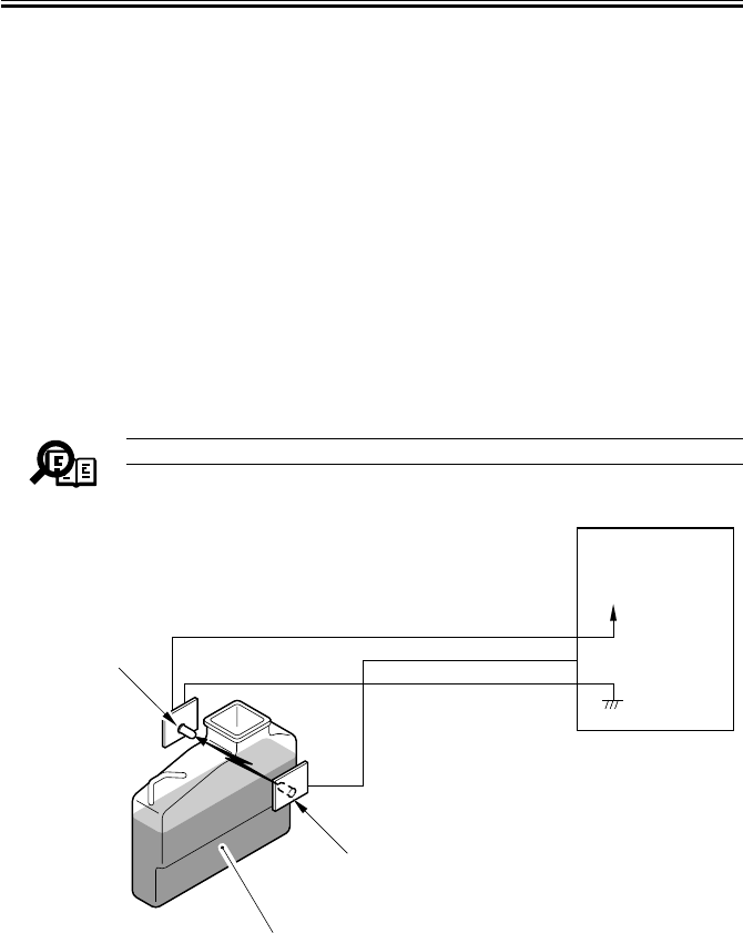
COPYRIGHT
©
2001 CANON INC. 2000 2000 2000 2000 CANON iR2200/iR2800/iR3300 REV.0 MAR. 2001
CHAPTER 4 IMAGE FORMATION SYSTEM
4-24 P
8.2 Monitoring the Waste Toner Case
The machine checks the waste toner case in reference to two levels.
The amount of waste toner inside the waste toner case is monitored by the waste toner
case full sensor (S2); the sensor is a pair of photosensors (light-emitting unit piece and
light-receiving piece). The machine will assume that the waste toner case has become full
when waste toner blocks the light between the two photosensors.
The DC controller PCB checks the waste toner case full sensor when the power is tuned
on and at time of delivery; it will assume a “waste toner full warning” after making a total of
100 prints after the waste toner case has become full, thereby indicating the Waste Toner
Case Full message on the control panel.
After the message Waste Toner Case Full is displayed in the control panel, the machine
will indicate 'E019' in its control panel if the case remains full upon generating about 2000
prints (cumulative).
If the waste toner case is not set, the light-blocking plate will block the light between the
photosensors, causing the Waste Toner Case Full message to appear.
Memo
The light between the photosensors is not visible to the eye.
F04-802-01
DC controller PCB
J311-B7
-B9
-B8
Waste toner case full signal
Waste toner case
full sensor
(light-emitting)
Waste toner case
full sensor
(light-receiving)
+5V
Waste toner case
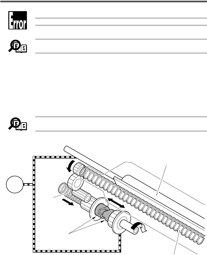
COPYRIGHT
©
2001 CANON INC. 2000 2000 2000 2000 CANON iR2200/iR2800/iR3300 REV.0 MAR. 2001
CHAPTER 4 IMAGE FORMATION SYSTEM
4-25 P
E019
Indicates that the waste toner case is full.
Memo
The waste toner case can hold waste toner equivalent of about 200,000
prints.
8.3 Locking of the Waste Toner Feedscrew
The waste toner feedscrew is rotated by the drive of the main motor transmitted by the
coupling built into the main motor drive assembly. The coupling is butted against the gear
used to rotate the screw by the work of a spring.
If the drum cleaning assembly is clogged with waste toner, the coupling will start to move
back and forth in the axial direction, causing a clicking sound.
Memo
The machine is not equipped with a sensor to detect the locking of the
waste toner feedscrew.
F04-803-01
Coupling
Spring
Photosensitive drum
M1
Main motor
Waste toner feedscrew

COPYRIGHT
©
2001 CANON INC. 2000 2000 2000 2000 CANON iR2200/iR2800/iR3300 REV.0 MAR. 2001
CHAPTER 4 IMAGE FORMATION SYSTEM
4-26 P
9 Disassembly and Assembly
The discussions that follow cover the machine’s mechanical characteristics and how to
disassemble/assemble the machine. Keep the following in mind whenever you work with the
machine:
1. The power plug must remain disconnected for safety when disassembling/assembling
the machine.
2. Unless otherwise noted, the machine may be assembled by reversing the steps used to
disassemble it.
3. The screws must be identified by type (length, diameter) and location.
4. The mounting screws used for the grounding wire and the varistors come with a washer,
which must not be left out when assembling the machine.
5. As a rule, the machine must not be operated with any of its parts removed.
6. The door switch or the main power switch must be turned off whenever the duplex unit
or the fixing/feeding unit must be slid out.
7. The toner must not be disposed of into fire to avid explosion.
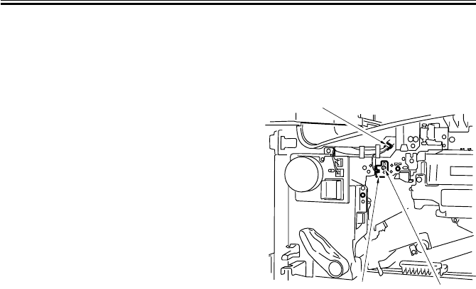
COPYRIGHT
©
2001 CANON INC. 2000 2000 2000 2000 CANON iR2200/iR2800/iR3300 REV.0 MAR. 2001
CHAPTER 4 IMAGE FORMATION SYSTEM
4-27 P
9.1 Pre-Exposure Lamp Unit
9.1.1 Removing the Pre-Exposure Lamp Unit
1) Remove the drum unit. (p. 4-28P)
-2) Remove the inside cover. (p. 7-14P)
3) Disconnect the connector [1], and re-
move the screw [2].
4) Remove the pre-exposure lamp unit [3].
F04-901-01
[1]
[2]
[3]
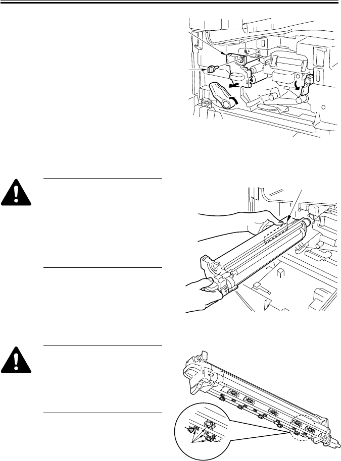
COPYRIGHT
©
2001 CANON INC. 2000 2000 2000 2000 CANON iR2200/iR2800/iR3300 REV.0 MAR. 2001
CHAPTER 4 IMAGE FORMATION SYSTEM
4-28 P
9.2 Photosensitive Drum
9.2.1 Removing the Drum Unit
1) Open the front cover.
2) Release the feeding assembly.
3) Release the developing assembly.
4) Remove the fixing screw [1].
5) Slide the drum unit [2] slowly out to the
front.
F04-902-01
When removing the photosensi-
tive drum, hold it by its long
hole [1], and take care not to
soil it.
The photosensitive drum is
highly susceptible to light. Once
outside the machine, be sure to
protect it against light.
F04-902-02
As many as 19 spurs [1] (4
type) are attached to the bottom
of the drum unit. Take care
when deciding where and how
to place the drum unit after tak-
ing it out of the machine.
F04-902-03
[1]
[2]
[1]
[1]

COPYRIGHT
©
2001 CANON INC. 2000 2000 2000 2000 CANON iR2200/iR2800/iR3300 REV.0 MAR. 2001
CHAPTER 4 IMAGE FORMATION SYSTEM
4-29 P
9.2.2 Cleaning the Photosensitive Drum
If the surface of the photosensitive drum
is soiled, wipe it with a flannel cloth coated
with toner. (Do not use paper, lint-free or
otherwise.)
Do not dry wipe it nor use sol-
vent. Further, never use drum
cleaning powder.
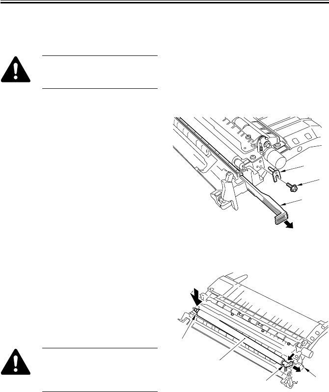
COPYRIGHT
©
2001 CANON INC. 2000 2000 2000 2000 CANON iR2200/iR2800/iR3300 REV.0 MAR. 2001
CHAPTER 4 IMAGE FORMATION SYSTEM
4-30 P
9.3 Transfer Charging Roller
9.3.1 Removing the Transfer Charging Roller
Do not touch the surface of the
transfer charging roller; other-
wise, faulty images can occur.
1) Remove the feeding assembly. (p. 5-
49P)
2) Pull out the static eliminator [1].
3) Remove the screw [2], and detach the
hinge pin [3].
F04-903-01
4) Shift the pre-transfer arm [2] (equipped
with a spring) together with the transfer
charging roller [1] to the left, and de-
tach it to the front.
5) While holding down the post-transfer
arm [3] from above, remove the transfer
charging roller [1] to the front.
When mounting it, be sure to fit
the bottom of the spring of the
pre-transfer arm into the seat
(dent) in the feeder frame [4].
F04-903-02
[1]
[2]
[3]
[1]
[2] [4]
[3] (1)
(2)

COPYRIGHT
©
2001 CANON INC. 2000 2000 2000 2000 CANON iR2200/iR2800/iR3300 REV.0 MAR. 2001
CHAPTER 4 IMAGE FORMATION SYSTEM
4-31 P
9.4 Charging Roller Solenoid
9.4.1 Removing the Charging Roller Solenoid (SL6)
1) Remove the photosensitive drum unit.
(p. 4-28P)
2) Open the rear cover. (7 screws)
3) Remove the DC controller PCB. (p. 7-
17P)
4) Remove the four screws [1], and detach
the DC controller base [2].
F04-904-01
5) Disconnect the two connectors [1] of
the harness.
6) Remove the three screws [2], and shift
the duct unit [3] to the side, and slide it
out to the front.
F04-904-02
[1]
[1]
[1]
[2]
[1] [1]
[2]
[3]
[2]
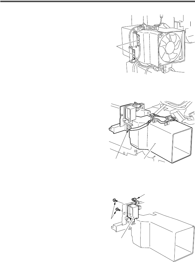
COPYRIGHT
©
2001 CANON INC. 2000 2000 2000 2000 CANON iR2200/iR2800/iR3300 REV.0 MAR. 2001
CHAPTER 4 IMAGE FORMATION SYSTEM
4-32 P
7) Free the claw, and detach the two relay
PCBs [1].
F04-904-03
8) Remove the faston [1] of the harness,
and detach the duct unit [2].
F04-904-04
9) Remove the two screws [1], and discon-
nect the connector [2]; then, detach the
charging roller solenoid [3].
F04-904-05
[1] [2]
[1]
[3]
[2]
[1]
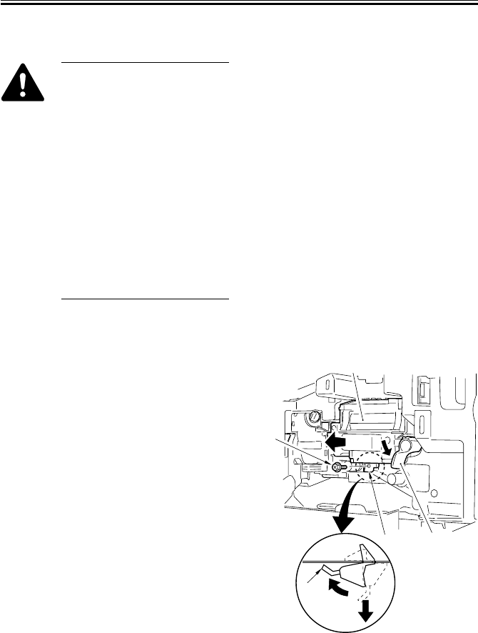
COPYRIGHT
©
2001 CANON INC. 2000 2000 2000 2000 CANON iR2200/iR2800/iR3300 REV.0 MAR. 2001
CHAPTER 4 IMAGE FORMATION SYSTEM
4-33 P
9.5 Developing Assembly
When disassembling/assem-
bling the developing assembly,
keep the following in mind:
1. When holding the developing
assembly, do not touch or
push the developing cylinder.
2. After mounting the develop-
ing assembly, be sure to fit
the developing assembly
stopper.
3. The blade and the blade base
of the blade base unit are ad-
justed to a high accuracy at
the factory. Do not disas-
semble the unit.
9.5.1 Removing the Developing Assembly
1) Open the front cover.
2) Shift down the developing assembly re-
leasing lever [1] to free the developing
assembly [2].
3) Remove the screw [3], and lift the bot-
tom of the developing assembly stopper
[4] to the front, and detach it to the bot-
tom.
4) Holding the grip on the developing as-
sembly, place your other hand on the
bottom of the developing assembly;
then, slide it out to the front.
F04-905-01
(1)
(2)
[1]
[2]
[3]
[4]
[4]
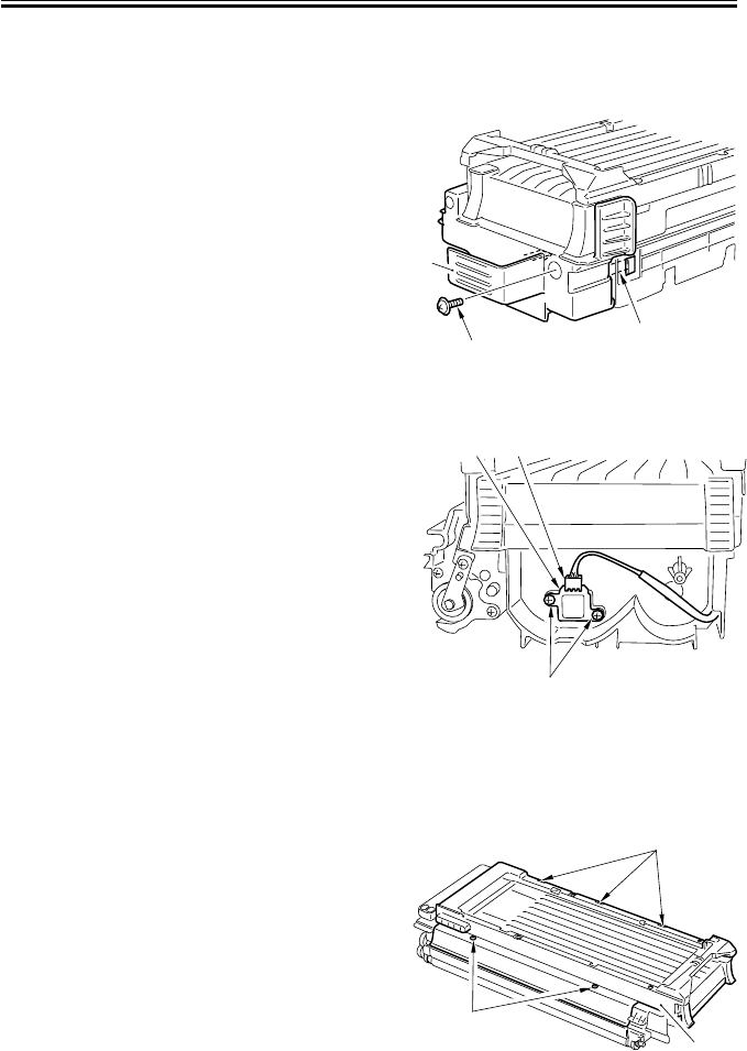
COPYRIGHT
©
2001 CANON INC. 2000 2000 2000 2000 CANON iR2200/iR2800/iR3300 REV.0 MAR. 2001
CHAPTER 4 IMAGE FORMATION SYSTEM
4-34 P
9.5.2 Removing the Grip Assembly
1) Remove the developing assembly. (p. 4-
33P)
2) Remove the screw [1] and free the three
claws [2]; then, detach the grip assem-
bly [3].
F04-905-02
9.5.3 Removing the Toner Sensor
1) Remove the grip assembly. (item 9.5.2)
2) Remove the two screws [1], and discon-
nect the connector [2].
3) Remove the toner sensor [3].
F04-905-03
9.5.4 Removing the Developing Assembly Upper Cover
1) Remove the grip assembly. (item 9.5.2)
2) Remove the two screws [1], and free the
three claws [2].
3) Remove the developing assembly upper
cover [3].
F04-905-04
[2]
[1]
[3]
[1]
[3] [2]
[1]
[2]
[3]
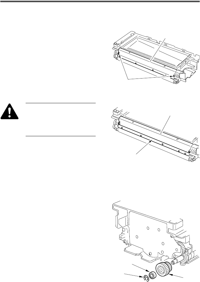
COPYRIGHT
©
2001 CANON INC. 2000 2000 2000 2000 CANON iR2200/iR2800/iR3300 REV.0 MAR. 2001
CHAPTER 4 IMAGE FORMATION SYSTEM
4-35 P
9.5.5 Removing the Blade Base Unit
1) Remove the developing assembly upper
cover. (p. 4-34P)
2) Remove the two screws [1], and detach
the blade base unit [2].
F04-905-05
The blade [1] and the blade base
[2] of the blade base unit are ad-
justed to a high accuracy at the
factory. Do not disassemble the
unit.
F04-905-06
9.5.6 Removing the Developing Cylinder
1) Remove the developing assembly upper
cover. (p. 4-34P)
2) Remove the E-ring [1], bearing [2], and
gear [3].
F04-905-07
[1]
[2]
[1]
[2]
[1]
[2]
[3]
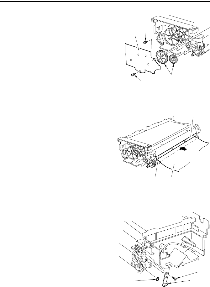
COPYRIGHT
©
2001 CANON INC. 2000 2000 2000 2000 CANON iR2200/iR2800/iR3300 REV.0 MAR. 2001
CHAPTER 4 IMAGE FORMATION SYSTEM
4-36 P
3) Remove the two screws [1] and the gear
cover [2].
4) Remove the two gears [3].
F04-905-08
5) Put copy paper [3] between the devel-
oping cylinder [1] and the blade [2].
F04-905-09
6) Remove the screw [1], and remove the
grounding plate [2].
7) Remove the grip ring [3].
F04-905-10
[1]
[1]
[2]
[3]
[1] [3]
[2]
[1]
[3] [2]
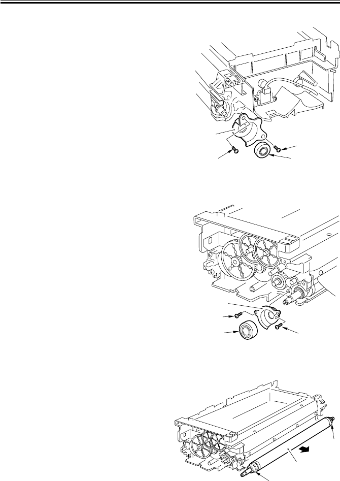
COPYRIGHT
©
2001 CANON INC. 2000 2000 2000 2000 CANON iR2200/iR2800/iR3300 REV.0 MAR. 2001
CHAPTER 4 IMAGE FORMATION SYSTEM
4-37 P
8) Remove the two screws [1], and detach
the support roller [2] and the front
sleeve holder [3].
F04-905-11
9) Remove the two screws [1], and detach
the support roller [2] and the sleeve
holder [3].
F04-905-12
10) Remove the developing cylinder [2] to-
gether with the two bearings [1].
F04-905-13
[1]
[2]
[1]
[3]
[1]
[1]
[3]
[2]
[1]
[1]
[2]
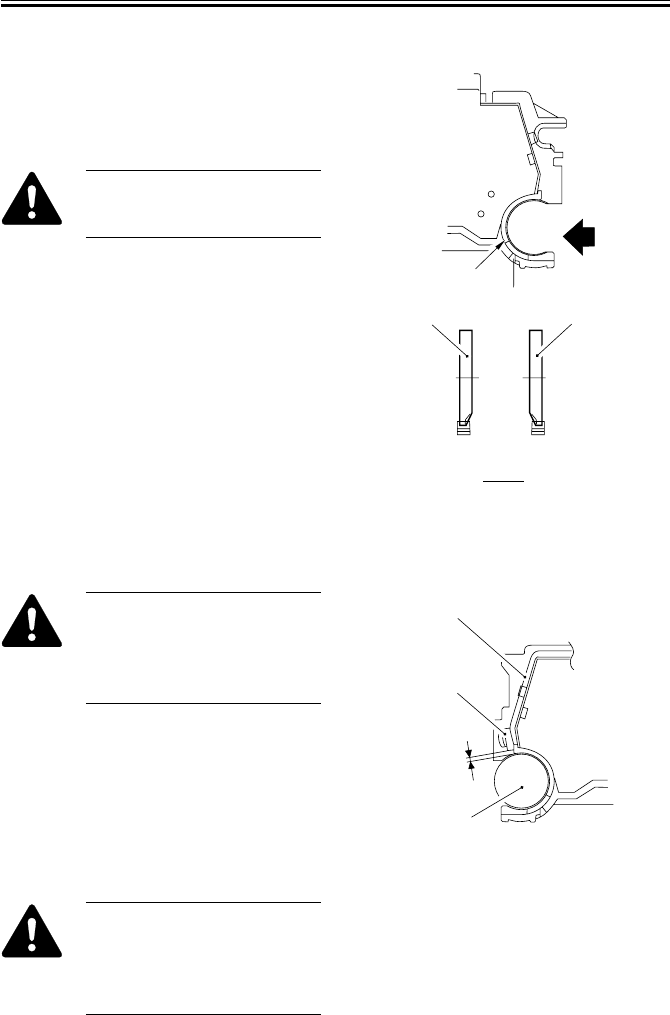
COPYRIGHT
©
2001 CANON INC. 2000 2000 2000 2000 CANON iR2200/iR2800/iR3300 REV.0 MAR. 2001
CHAPTER 4 IMAGE FORMATION SYSTEM
4-38 P
9.5.7 Positioning the Developing Assembly Magnetic Seal
1) The front magnetic seal [1] and the rear
magnetic seal [2] must be butted against
the opening [3] (stop reference) when
they are mounted.
Check to make sure that the
magnetic seal is in firm contact
with the casing.
F04-905-14
9.5.8 Mounting the Developing Assembly Blade
The blade [1] and the blade base
[2] of the blade base unit are ad-
justed to a high accuracy at the
factory. Do not disassemble the
unit.
If you happen to have removed the blade,
adjust its position so that the gap between
the blade and the developing cylinder [3] is
0.21 ± 0.03 mm using a gap gauge (CK-
0057-000).
F04-905-15
The surface of the developing
cylinder is highly susceptible to
scratches. Be sure to fit the gap
gauge on ends of the developing
cylinder.
A
A
[1]
[2] [3]
[1] ([2])
[1]
[2]
[3]
0.21±0.03mm

COPYRIGHT
©
2001 CANON INC. 2000 2000 2000 2000 CANON iR2200/iR2800/iR3300 REV.0 MAR. 2001
CHAPTER 4 IMAGE FORMATION SYSTEM
4-39 P
9.6 Removing the Paper Lint
9.6.1 Removing the Paper Lint
1) Open the front cover.
2) Remove the paper lint cleaning cover
[1] by inserting a flat-blade screwdriver.
F04-906-01
3) Slide out the paper lint cleaning lever
[1], and move it back and forth.
F04-906-02
9.6.2 When Removing the Paper Lint
Execute APVC correction in service
mode. (p. 5-67T)
APVC correction
COPIER>FUNCTION>DPC>
D-GAMMA
[1]
[1]
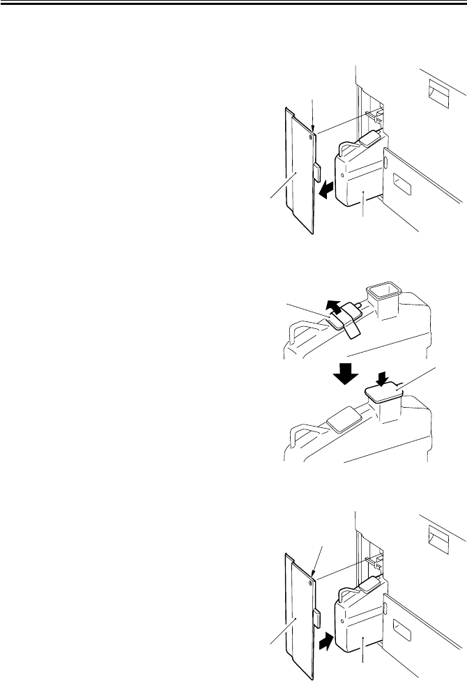
COPYRIGHT
©
2001 CANON INC. 2000 2000 2000 2000 CANON iR2200/iR2800/iR3300 REV.0 MAR. 2001
CHAPTER 4 IMAGE FORMATION SYSTEM
4-40 P
9.7 Waste Toner Case
9.7.1 Replacing the Waste Toner Case
1) Remove the screw [1], and detach the
waste toner case cover [2].
2) Take out the waste toner case [3].
F04-907-01
3) Remove the case cap [1] taped to the
waste toner case; then, put the cap to the
case.
F04-907-02
4) Fit the new waste toner case [1], and
mount the waste toner case cover [2]
with a screw [3].
F04-907-03
[1]
[2]
[3]
[1]
[1]
[3]
[2]
[1]

COPYRIGHT
©
2001 CANON INC. 2000 2000 2000 2000 CANON iR2200/iR2800/iR3300 REV.0 MAR. 2001
CHAPTER 4 IMAGE FORMATION SYSTEM
4-41 P
9.7.2 Cleaning the Waste Toner Case
1) Remove the screw [1], and detach the
waste toner case cover [2].
2) Take out the waste toner case [3].
F04-907-04
3) Dispose of the waste toner collecting
inside the waste toner case.
4) Clean both inside and the outside of the
waste toner case [1] (area A, indicated
by shading) with alcohol.
In particular, take care not to leave any
dirt on the inside and the outside of the
area around the round recess.
F04-907-05
5) Fit the waste toner case [1] back in the
machine, and mount the waste toner
case cover [2] with a screw [3].
F04-907-06
[1]
[2]
[3]
[1]
A
[3]
[2]
[1]

COPYRIGHT
©
2001 CANON INC. 2000 2000 2000 2000 CANON iR2200/iR2800/iR3300 REV.0 MAR. 2001
CHAPTER 5
PICK-UP/FEEDING SYSTEM

COPYRIGHT
©
2001 CANON INC. 2000 2000 2000 2000 CANON iR2200/iR2800/iR3300 REV.0 MAR. 2001
CHAPTER 5 PICK-UP/FEEDING SYSTEM
5-1 P
1 Outline
1.1 Specifications and Construction
T05-101-01 shows the major functions and the construction of the pickup/feeding system:
Item Description
Paper feed reference Center
Paper stack Cassette (1, 2): 500 sheets each (80 g/m2)
Multifeeder: 50 sheets (80 g/m2)
Paper size switching Cassette (1, 2): by user
Multifeeder:by user
Duplex copying Through path
Related user mode Cassette auto selection (enabled/disabled)
Paper icon
Related mechanical adjustments Cassette horizontal registration adjustment
Multifeeder horizontal adjustment
T05-101-01
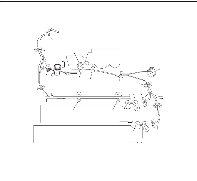
COPYRIGHT
©
2001 CANON INC. 2000 2000 2000 2000 CANON iR2200/iR2800/iR3300 REV.0 MAR. 2001
CHAPTER 5 PICK-UP/FEEDING SYSTEM
5-2 P
1.2 Arrangement of Rollers
F05-101-01
The following rollers are mainly used to move paper:
Ref. Name
[1] Pickup roller
[2] Feeding roller
[3] Separation roller
[4] pull-out roller
[5] Pre-registration roller
[6] Registration roller
[7] Pre-transfer roller
[8] Photosensitive drum
[9] Transfer charging roller
[10] Fixing delivery roller
[11] Delivery vertical path roller
[12] Delivery roller
[13] Duplex roller
[14] Multifeeder pickup roller
[7] [6]
[9]
[10] [5]
[1]
[13] [13]
[1]
[2] [4]
[2] [4]
[3]
[3]
[14]
[8]
[11]
[12]

COPYRIGHT
©
2001 CANON INC. 2000 2000 2000 2000 CANON iR2200/iR2800/iR3300 REV.0 MAR. 2001
CHAPTER 5 PICK-UP/FEEDING SYSTEM
5-3 P
1.3 Arrangement of Motors, Clutches, and Solenoids
F05-102-01
The following motors, clutches, and solenoids are used to move paper:
Notation Name
M1 Main motor
M2 Pickup motor
M5 Delivery motor
M6 Duplex motor
M9 Registration motor
CL1 Vertical path clutch
CL2 Multifeeder clutch
SL1 Pickup DOWN solenoid
SL5 Multifeeder rely releasing solenoid
M6
M1M5
M9
CL2
CL1
SL5
SL1
M2
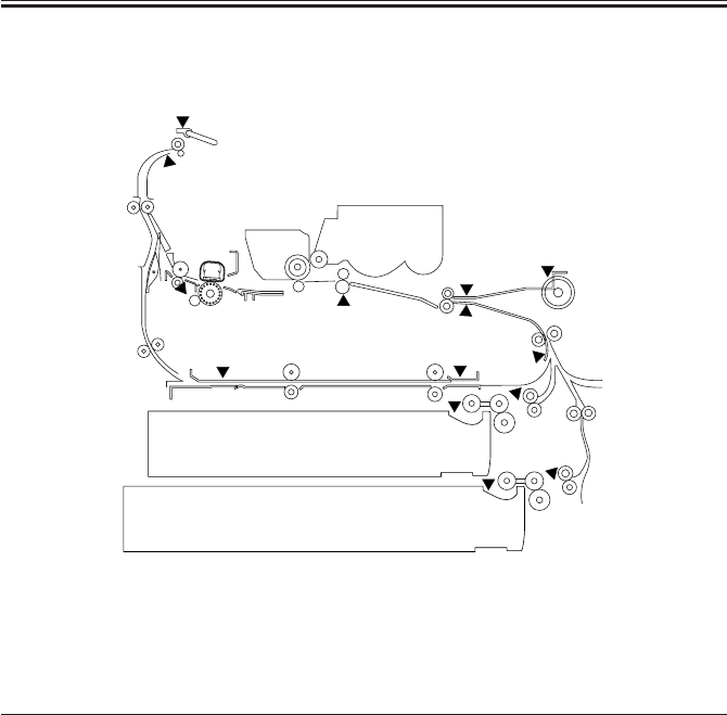
COPYRIGHT
©
2001 CANON INC. 2000 2000 2000 2000 CANON iR2200/iR2800/iR3300 REV.0 MAR. 2001
CHAPTER 5 PICK-UP/FEEDING SYSTEM
5-4 P
1.4 Arrangement of Sensors
F05-103-01
The following sensors are used to monitor the movement of paper:
Notation Name Delay jam Stationary jam Power-on
stationary jam
PS1 Cassette 1 paper sensor No No No
PS2 Cassette 2 paper sensor No No No
PS7 Cassette 1 retry paper sensor Yes No No
PS8 Cassette 2 retry paper sensor Yes No No
PS9 Pre-registration paper sensor Yes No No
PS10 Registration paper sensor Yes Yes No
PS11 Horizontal registration paper sensor No No No
PS12 Image leading edge paper sensor Yes No No
PS13 fixing feeding sensor Yes Yes No
PS15 No. 1 delivery paper sensor Yes Yes No
PS16 No. 1 delivery full sensor No No No
PS17 Duplex inlet paper sensor Yes No No
PS18 Duplex outlet paper sensor Yes No No
PS22 Multifeeder paper sensor No No No
T05-102-01
PS11
PS10
PS12
PS13
PS16
PS15
PS9
PS18
PS17
PS1
PS7
PS8
PS2
PS22
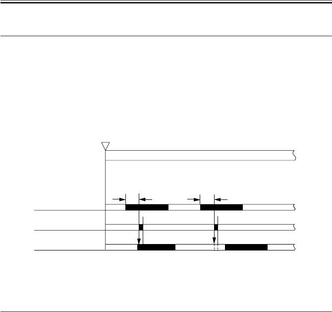
COPYRIGHT
©
2001 CANON INC. 2000 2000 2000 2000 CANON iR2200/iR2800/iR3300 REV.0 MAR. 2001
CHAPTER 5 PICK-UP/FEEDING SYSTEM
5-5 P
2 Detecting Jams
2.1 Sequence of Operations (jam detection)
2.1.1 Delay Jam
a. Cassette Pickup Assembly (cassette 1, 2)
The leading edge of paper does not reach the sensor within a specific period of time after
the motor has gone ON.
F05-201-01
Pickup assembly Motor Sensor
Cassette 1 Pickup motor (M2) Cassette 1 retry sensor (PS7)
Cassette 2 Pickup motor (M2) Cassette 2 retry sensor (PS8)
T05-201-01
Start key ON
or
PRINT setting ON
INTR / PRINT
Motor N-1
Jam check
Sensor N
[1]
Normal Error
[1]
[1]:specific feed period.

COPYRIGHT
©
2001 CANON INC. 2000 2000 2000 2000 CANON iR2200/iR2800/iR3300 REV.0 MAR. 2001
CHAPTER 5 PICK-UP/FEEDING SYSTEM
5-6 P
b. Other Delay Jams
Other than pickup sensor delay jams, jams are found by other sensors at the following
timing of detection.
The period of time for travel between sensor N-1 and delay jam sensor N are monitored
with reference to the clock pulses from the main motor; a delay jam will be identified if the
leading edge of paper does not reach the delay jam sensor N in question within a specific
period of time after the sensor N-1 goes ON.
F05-201-02
Notation Name Delay jam
PS9 Pre-registration paper sensor Yes
PS10 Registration paper sensor Yes
PS12 Image leading edge sensor Yes
PS13 Fixing feeding sensor Yes
PS15 No. 1 delivery paper sensor Yes
PS17 Duplex inlet paper sensor Yes
PS18 Duplex outlet paper sensor Yes
PS22 Multifeeder paper No
T05-201-02
Start key ON
or
PRINT settings ON
INTR / PRINT
Sensor N-1
Jam check
Sensor N Normal Error
[1] [1]
[1]:specific feed period.
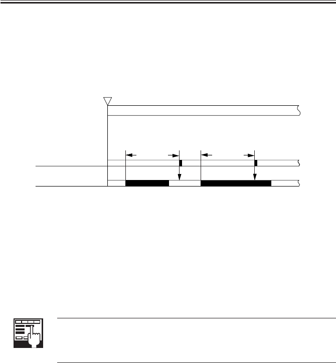
COPYRIGHT
©
2001 CANON INC. 2000 2000 2000 2000 CANON iR2200/iR2800/iR3300 REV.0 MAR. 2001
CHAPTER 5 PICK-UP/FEEDING SYSTEM
5-7 P
2.1.2 Stationary Jam
a. Common Stationary Jam
Registration paper sensor (PS10), Fixing feeding sensor (PS13), No. 1 delivery paper sen-
sor (PS15)
F05-201-03
b. Power-On Stationary Jam
A stationary jam at power on is identified based on the presence/absence of paper over a
specific sensor about 1 sec after the control panel power switch is turned on.
2.1.3 Jam History
The host machine maintains a history of jams that occur inside it, and the history may be
checked in service mode.
COPIER>DIPLAY>JAM
Use it to indicate jam data.
COPIER>FUNCTION>JAM-HIST
Use it to clear the jam history.
The following are retained in response to a jam, and brought back to use after the jam has
been removed.
• Remaining number of copies to make
• Selected copying mode
Start key ON
or
PRINT setting ON
INTR / PRINT
Jam check
Sensor N
L + A
Normal Error
L + A
(L: paper length; A: specific feed distance)
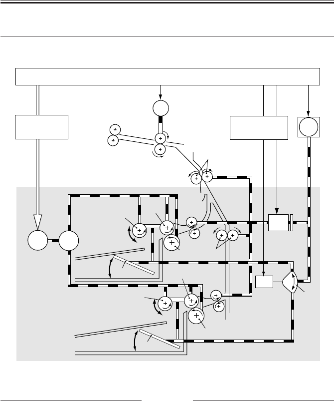
COPYRIGHT
©
2001 CANON INC. 2000 2000 2000 2000 CANON iR2200/iR2800/iR3300 REV.0 MAR. 2001
CHAPTER 5 PICK-UP/FEEDING SYSTEM
5-8 P
[8]
M2
M9
M1
CL1
[10]
SL1
[2]
[4]
[3]
[2]
[4]
[5]
[5]
[3]
[7]
[6]
[11] [11]
[1]
[9]
3 Pickup Assembly
3.1 Pickup Control System
F05-301-01
Notation Name
[9] Pre-registration roller
[10] DC controller PCB
[11] Cassette pickup PCB
M1 Main motor
M2 Pickup motor
M5 Registration motor
CL1 Vertical path clutch
SL1 Pickup DOWN solenoid
Notation Name
[1] Gear
[2] Pickup roller
[3] Feeding roller
[4] Separation roller
[5] Lifter
[6] Vertical path roller
[7] Cam
[8] Registration roller

COPYRIGHT
©
2001 CANON INC. 2000 2000 2000 2000 CANON iR2200/iR2800/iR3300 REV.0 MAR. 2001
CHAPTER 5 PICK-UP/FEEDING SYSTEM
5-9 P
3.2 Outline
The paper inside the cassette is held up by the lifter, and remains in contact with the
pickup roller when pickup takes place:
(1) The pickup motor (M2) is used to drive the pickup roller. The pickup roller is moved
down in relation to the feeding roller, and is brought into contact with paper only when
pickup takes place.
(2) The pickup roller is moved down when the cam released by the DOWN solenoid
(SL1) rotates by the drive of the main motor (M1).
The feeding roller and the separation roller serve to make sure that only one sheet of pa-
per from the pickup roller is sent to the feeding path; the No. 2 registration roller and the
vertical path roller then forwards the paper as far as the registration roller.
The drive for the vertical path roller and the No. 2 registration roller is provided by the
pickup motor (M2) through the vertical path clutch (CL1).
The registration roller is driven by the registration motor (M9).

COPYRIGHT
©
2001 CANON INC. 2000 2000 2000 2000 CANON iR2200/iR2800/iR3300 REV.0 MAR. 2001
CHAPTER 5 PICK-UP/FEEDING SYSTEM
5-10 P
3.3 Sequence of Operations (pickup)
a. Cassette 1
• A4, 2 Copies, Continuous
F05-303-01
Regist motor(M9)
Pickup down
solenoid(SL1)
Vertical path
roller clutch(CL1)
Pickup motor(M2)
Pre-registration
paper sensor(PS9)
Registration
paper sensor(PS10)
Print start
LSTR
PRINT
Retry sensor(PS7)

COPYRIGHT
©
2001 CANON INC. 2000 2000 2000 2000 CANON iR2200/iR2800/iR3300 REV.0 MAR. 2001
CHAPTER 5 PICK-UP/FEEDING SYSTEM
5-11 P
3.4 Operation of the Cassette Lifter
The lifter is operated as necessary in the course of printing to maintain the stack of sheets
to a specific height.
3.4.1 Operation of the Lifter During Printing
The lifter is controlled by the movement of the pickup roller shaft. When the pickup roller
shaft pushes the lifter trigger lever, the cam is released, and the lifter starts to move up until
the lifter trigger lever stops the cam.
1) Each time the pickup roller DOWN so-
lenoid (SL1) goes ON, the pickup roller
shaft [2] moves down to initiate pickup
operation.
2) When the sheets [6] decrease and, as a
result, the descent distance [3] of the
pickup roller increases, the pickup roller
shift pushes down the lifter trigger lever
[4].
3) When the lever is pushed down, the cam
[5] is released, causing it to rotate.
4) The rotation of the cam turns the eccen-
tric cam [3] mounted to the same shaft.
The eccentric cam operates the lifter UP
lever [2] to move up the lifter gear [1].
5) The lifter moves up and, as a result, the
paper stack moves up; when the pickup
roller shaft reaches a specific height, the
lifter trigger lever is drawn back by the
work of a spring, thereby stopping the
cam. F05-304-01
The foregoing series of operation is repeated to maintain the height of the paper stack to a
specific level. The cassette pickup operation ends when paper runs out and the cassette pa-
per sensor detects the absence of paper.
[1] [2]
[4]
[7] [6]
[3]
[5]
SL1
[1]
[2]
[3]

COPYRIGHT
©
2001 CANON INC. 2000 2000 2000 2000 CANON iR2200/iR2800/iR3300 REV.0 MAR. 2001
CHAPTER 5 PICK-UP/FEEDING SYSTEM
5-12 P
3.4.2 Releasing the Lifter
The lifter is released mechanically when the cassette is slid out. When the machine is in
standby state, the lifter gear is held in place by the lifter gear retaining lever. When the cas-
sette is slid out, the lifter gear retaining lever is freed, thereby allowing the lifter to move
down.
If the main power is cut while the lifter is moving up, the lifter is held up
with the claw used to move up the lifter remaining in contact with the lifter
gear; the lifter will not be fully released in this condition, and damage can
occur if the cassette is forced out. Be sure to turn off and then on the main
power so that the machine will be in standby state whenever the cassette
must be slid out.

COPYRIGHT
©
2001 CANON INC. 2000 2000 2000 2000 CANON iR2200/iR2800/iR3300 REV.0 MAR. 2001
CHAPTER 5 PICK-UP/FEEDING SYSTEM
5-13 P
3.5 Cassette Pickup Operation
3.5.1 Rotating the Pickup Roller
The drive used to rotate the pickup roller is transmitted through gears. The cassette motor
rotates clockwise and counterclockwise to initiate pickup operation of the cassette 1/2.
3.5.2 Switching the Pickup Roller Drive
When the pickup roller rotates clockwise, the gear 1 moves up to drive the pickup roller
of the upper cassette holder; when the motor rotates counterclockwise, on the other hand,
the gear 1 moves down to drive the pickup roller of the lower cassette holder. The figure be-
low shows how the drive of the pickup roller is controlled.
3.5.3 Pickup Roller Shaft Reference
The up and down movement of the pickup roller when the cassette is set in the machine is
driven with reference to the position of the pickup roller shaft.
[1] Pickup motor (M2)
[2] Gear 1
F05-305-01
[2]
[1]

COPYRIGHT
©
2001 CANON INC. 2000 2000 2000 2000 CANON iR2200/iR2800/iR3300 REV.0 MAR. 2001
CHAPTER 5 PICK-UP/FEEDING SYSTEM
5-14 P
Pickup Drive for the Upper Cassette Holder (pickup motor in CW rotation)
F05-305-02
Pickup Drive for the Lower Cassette Holder (pickup motor CCW rotation)
F05-305-03
Feeding roller
Pickup roller
Separation roller
Gear 1
Cassette pickup motor (M2)
Cassette pickup motor (M2)
Feeding roller
Pickup roller
Separation roller
Gear 1
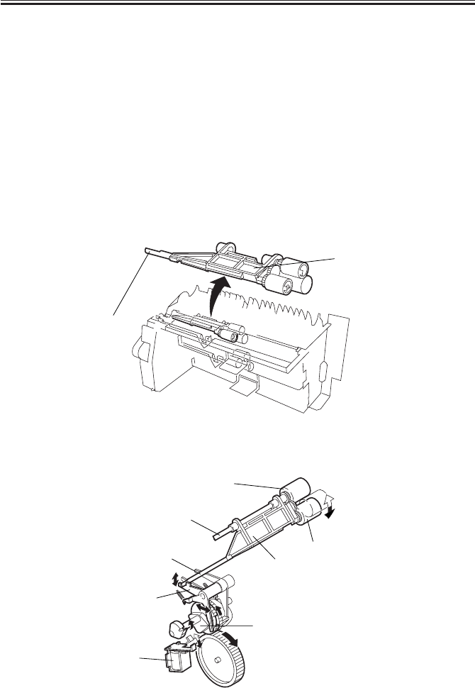
COPYRIGHT
©
2001 CANON INC. 2000 2000 2000 2000 CANON iR2200/iR2800/iR3300 REV.0 MAR. 2001
CHAPTER 5 PICK-UP/FEEDING SYSTEM
5-15 P
3.6 Moving Up/Down the Pickup Roller
The pickup roller and the feeding roller are supported by a roller holder, and the pickup
roller is moved up and down in relation to the feeding roller. In standby state, the pickup
roller is at the uppermost position; during pickup operation, on the other hand, it moves
down to reach the paper surface. It operates as follows to pick up a single sheet of paper:
1) When the pickup solenoid (SL1) goes ON, the drive of the main motor (M1) causes the
cam 1 to rotate.
2) The rotation of the cam 1 causes the pickup lever to swing.
3) The swing of the lever causes the pickup roller to move down to come into contact with
the paper, and the pickup motor (M2) starts pickup operation.
4) The rotation of the cam 1 moves up the pickup roller shaft.
Arrangement of the Pickup Roller
F05-306-01
Up/Down Movement of the Pickup Roller Shaft
F05-306-02
Pickup roller
shaft
Roller holder
Feeding roller
Pickup solenoid
(SL1)
Pickup lever
Pickup roller
ON
Roller holder
Cam 1
(rotates when SL1 goes ON)
Feeding roller shaft
Pickup roller shaft
ON
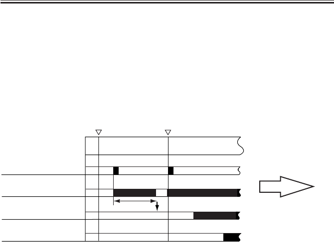
COPYRIGHT
©
2001 CANON INC. 2000 2000 2000 2000 CANON iR2200/iR2800/iR3300 REV.0 MAR. 2001
CHAPTER 5 PICK-UP/FEEDING SYSTEM
5-16 P
3.7 Pickup Retry Operation
When a delay is detected by a pickup sensor because of wear on the pick roller, pickup
retry operation is executed. If a delay is still detected after a retry, the control panel indicates
the Jam message.
3.7.1 Conditions for Detecting a Delay
Paper does not reach the retry sensor when it has been moved over a specific distance af-
ter the pickup DOWN solenoid (SL1) has gone ON.
*1:retry operation is executed if paper does not arrive after moving it over ‘distance to the retry sen-
sor + 100 mm’.
F05-307-01 Retry Operation
Pick DOWN solenoid
Pickup motor
Retry paper sensor *1
Pre-registration paper
sensor
Retry operation started
Start key ON
Hereafter, the same
sequence as common
pickup sequence.
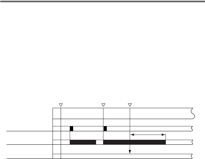
COPYRIGHT
©
2001 CANON INC. 2000 2000 2000 2000 CANON iR2200/iR2800/iR3300 REV.0 MAR. 2001
CHAPTER 5 PICK-UP/FEEDING SYSTEM
5-17 P
3.7.2 Paper Retraction
If a delay is detected once again after a retry and the jam must be removed, the paper can
become torn if an attempt is made form the cassette side. To enable removal from the right
cover side, the following operation takes plate:
1) After detecting the jam, the retracting roller is driven for a period equivalent to a dis-
tance over which paper may be moved 10 cm. The paper will be moved to a point where
it is in view when the right cover is opened.
2) The control panel indicates an instruction to the effect that the jam may be removed
from the right cover side.
3) The right cover may be opened to remove the jam. If the jam is not in view when the
right cover is opened, it may be removed from the cassette side.
*1:paper moved by the retracting roller for a equivalent of a distance over which paper may be
moved 10 cm.
F05-307-02
Pickup roller DOWN
solenoid
Pickup motor
Retry sensor
Start key ON Retry started
Jam indicator
(removal from right cover side)
*1
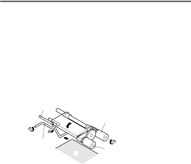
COPYRIGHT
©
2001 CANON INC. 2000 2000 2000 2000 CANON iR2200/iR2800/iR3300 REV.0 MAR. 2001
CHAPTER 5 PICK-UP/FEEDING SYSTEM
5-18 P
3.8 Operation Other Than Cassette Pickup (standby)
When the cassette is slid into or out of the machine, the following takes place:
3.8.1
Moving Up the Lifter/Moving Down the Pickup Roller Shaft (cassette slid in)
1) Moving Down the Pickup Roller Shaft
With the power on, when the cassette is slid into the machine, the pickup roller moves
down until it comes into contact with the paper surface as follows:
• The cassette rear end pushes in the lever 1 of the pickup unit.
• When the cassette size detection mechanism goes ON, the main motor (M1) and the
pickup solenoid (SL1) go ON to swing the pickup lever.
F05-308-01
[4]
[3]
[2]
[5]
[1]
[1] Cassette
[2] Lever 1
[3] Pickup roller
[4] Feeding roller
[5] Pickup roller shaft

COPYRIGHT
©
2001 CANON INC. 2000 2000 2000 2000 CANON iR2200/iR2800/iR3300 REV.0 MAR. 2001
CHAPTER 5 PICK-UP/FEEDING SYSTEM
5-19 P
2) Moving Up the Lifter
When the main power is turned on with the cassette set in the machine or the cassette is
slid in while the machine is in standby state, the pickup roller shaft moves down to push
down the lifter trigger lever.
The cam is released when the pickup roller shaft pushes one side of the lifter trigger lever,
and the drive from the main motor (M1) move sup the lifter.
When the pickup roller remaining in contact with the paper surface moves up to a specific
height, the movement of the levers cause the pickup roller shaft to return to the uppermost
position to end the upward movement of the lifter.
F05-308-02
Pickup roller shaft
Lifter trigger lever
Cam
M1
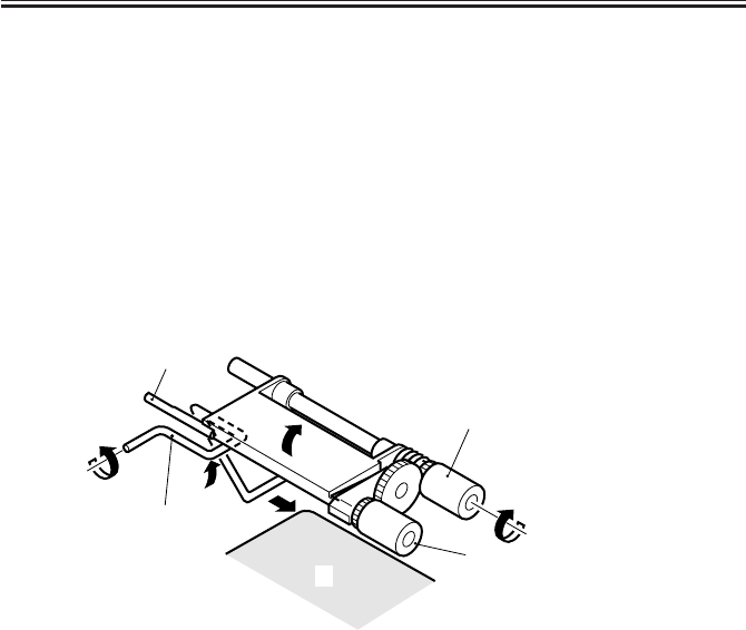
COPYRIGHT
©
2001 CANON INC. 2000 2000 2000 2000 CANON iR2200/iR2800/iR3300 REV.0 MAR. 2001
CHAPTER 5 PICK-UP/FEEDING SYSTEM
5-20 P
3.8.2 Moving Up the Pickup Roller Shaft and Releasing the Separation
Roller Pressure (cassette slid out)
When the cassette is slid out of the machine, the pickup roller shaft is mechanically
moved up and the separation roller pressure is also released.
1) Moving Up the Pickup Roller Shaft and Releasing the Separation Roller Pressure
When the cassette is slid out, the lever 1 rotates by the work of a spring. When the lever 1
rotates, the pickup roller shaft moves so that the pickup roller and the cassette will not inter-
fere with each other.
F05-308-03
[4]
[3]
[2]
[5]
[1]
[1] Cassette
[2] Lever 1
[3] Pickup roller
[4] Feeding roller
[5] Pickup roller shaft
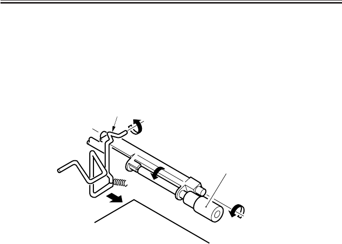
COPYRIGHT
©
2001 CANON INC. 2000 2000 2000 2000 CANON iR2200/iR2800/iR3300 REV.0 MAR. 2001
CHAPTER 5 PICK-UP/FEEDING SYSTEM
5-21 P
2) Releasing the Separation Roller Pressure
The lever 1 is provided with a protrusion used to push down the separation roller assem-
bly. When the cassette is slid out, the lever 1 rotates causing the separation roller to move
down, thereby removing the pressure between the separation roller and the feeding roller.
F05-308-04
b. Releasing the Lifter
The lifter is released when the cassette is slid out while the machine is in standby state.
[1]
[2]
[3]
[1] Cassette
[2] Protrusion of lever 1
[3] Separation roller
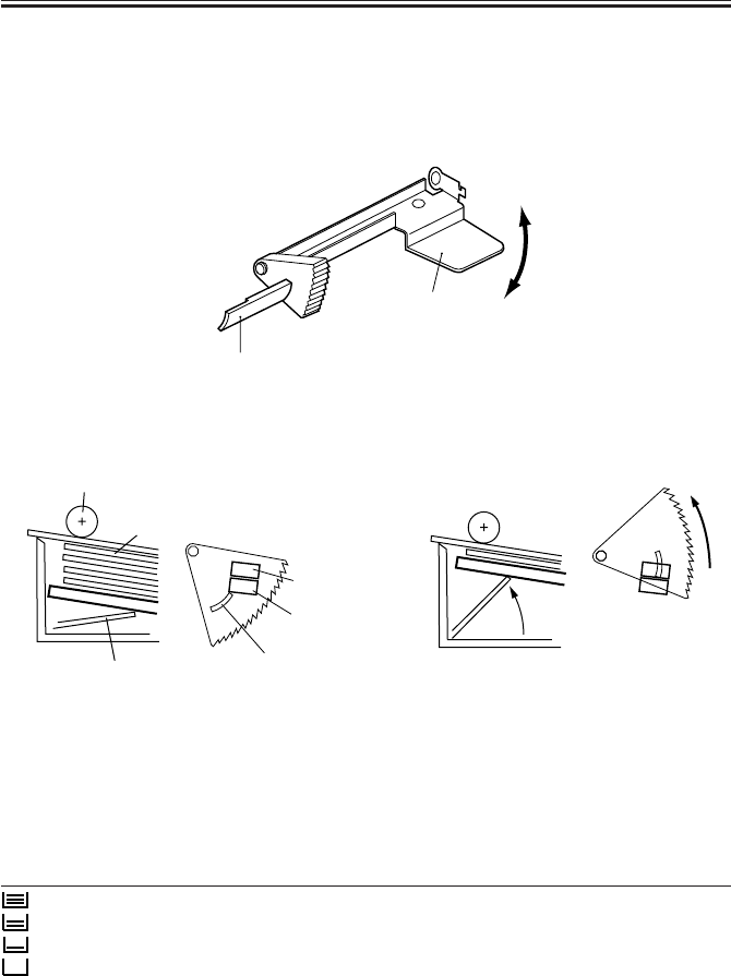
COPYRIGHT
©
2001 CANON INC. 2000 2000 2000 2000 CANON iR2200/iR2800/iR3300 REV.0 MAR. 2001
CHAPTER 5 PICK-UP/FEEDING SYSTEM
5-22 P
If the cassette is full of paper If the cassette is empty of paper
Note: The diagram is a view from the rear of the copying machine.
F05-309-02 Detecting the Level of Paper in the Cassette (upper cassette holder)
The amount of paper inside the cassette is indicated on the control panel in terms of four
levels (including the absence of paper).
Indication Level Sensor 1 Sensor 2
3 bars 100% to about 50% of capacity 0 0
2 bars 50% to about 10% of capacity 1 0
1 bar about 10% or less of capacity 1 1
no bar No paper - -
0: light-blocking plate over the sensor.
1: light-blocking plate not over the sensor.
T05-309-01
Sensor 1
Sensor 2
Light-blocking plate
Lifter
Paper
Pickup roller
3.9 Detecting the Level of Paper
The level of paper inside the cassette is detected by the light-blocking plate of the lifter
gear and a sensor in relation to the distance over which the lifter moves up. When paper
starts to run out, the lifter gradually moves up; when paper fully runs out, the cassette paper
sensor (Q1604 for cassette 1) identifies the condition as indicating the absence of paper.
F05-309-01
Lifter
Light-blocking plate
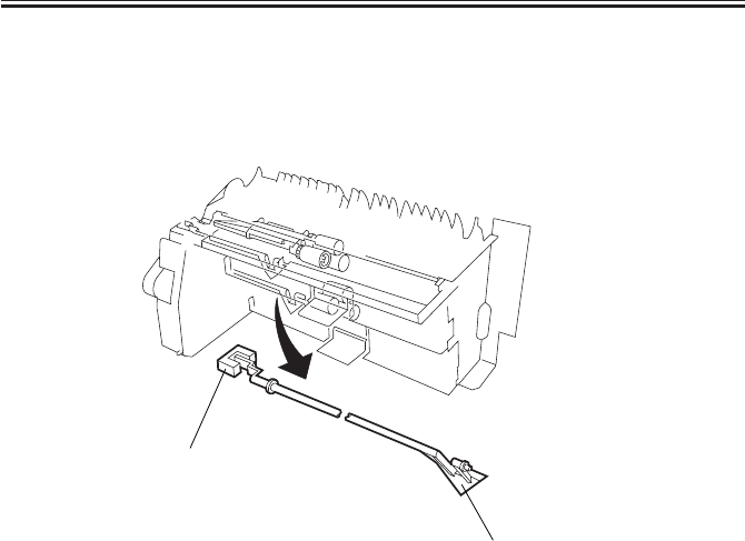
COPYRIGHT
©
2001 CANON INC. 2000 2000 2000 2000 CANON iR2200/iR2800/iR3300 REV.0 MAR. 2001
CHAPTER 5 PICK-UP/FEEDING SYSTEM
5-23 P
3.10
Detecting the Presence/Absence of Paper Inside the Cassette
When the cassette runs out of paper, the paper detecting lever falls through the detecting
hole of the cassette, causing the light-blocking plate linked to the lever to block the light of
the photointerrupter (Q1604 for cassette 1; Q1605 for cassette 2).
F05-310-01
Paper detecting lever
Q1604: cassette 1.
Q1605: cassette 2.
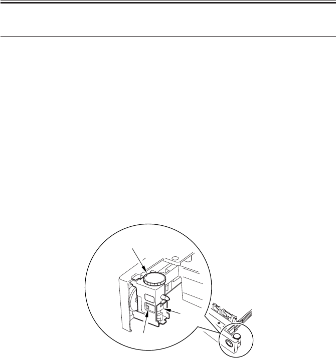
COPYRIGHT
©
2001 CANON INC. 2000 2000 2000 2000 CANON iR2200/iR2800/iR3300 REV.0 MAR. 2001
CHAPTER 5 PICK-UP/FEEDING SYSTEM
5-24 P
4 Identifying the Size of Paper
The size of paper inside the cassette may be set using the dial on the cassette. The AB-
setting and the Inch-setting are switched over using the switch found next to the dial.
4.1 Identifying the Size
The dial on the cassette may be set to any of 16 stops.
When the dial is set to an appropriate paper size and the cassette is slid into the machine,
the four cassette size detecting switches recognize the size of the paper based on the result-
ing combination of indentations and protrusions of the size detecting cam.
4.2 AB-/Inch-Setting Switch
The AB-setting and the Inch-setting is switched over using the switch found next to the
dial.
When the cassette is slid into the machine, the cassette side detecting switch recognizes
the paper configuration (AB or Inch)
F05-402-01
[1]
[3]
[2]
[1] Dial
[2] AB-/Inch-setting switch
[3] Size detecting cam
COPYRIGHT
©
2001 CANON INC. 2000 2000 2000 2000 CANON iR2200/iR2800/iR3300 REV.0 MAR. 2001
CHAPTER 5 PICK-UP/FEEDING SYSTEM
5-25 P
4.3 Paper Size
The width and the length of paper are identified by the dial mounted to the cassette is set.
The following diagram shows the rotary label attached to the dial, and the following table
shows the paper sizes that are recognized by the machine:
F05-403-01 Rotary Label
Note 1:U Cassette
The following are special types of paper:
U1: FOOLSCAP/OFFICIO/A-OFFICIO/E-OFFICIO/B-OFFICIO/A-LGL
U2: FOLIO U3: A-FLS U4: G-LTR U5: G-LTR(R)
U6: G-LGL U7: X-LGL U8: K-LGL(R)
A3
A4R
A4
A5R
A5
U3
B5
B5R
B4
U1
U2
LGL
LTR-R
LTR
STMT-R
STMT
U8
11×17
U4
U5
U6
U7
A/B-setting rotary label Inch-setting rotary label

COPYRIGHT
©
2001 CANON INC. 2000 2000 2000 2000 CANON iR2200/iR2800/iR3300 REV.0 MAR. 2001
CHAPTER 5 PICK-UP/FEEDING SYSTEM
5-26 P
4.4 Paper Size List
(AB-setting)
Combination of states of cassette size detection switches
Main scanning Sub scanning
Cassette name SW1 SW2 SW3 SW4 SW5 direction (mm) direction(mm)
No cassette OFF OFF OFF OFF OFF - -
A5 OFF ON ON OFF ON 210 148
A5R OFF ON ON ON ON 148 210
A4 OFF ON ON ON OFF 297 210
A4R OFF ON OFF ON OFF 210 297
A3 OFF ON OFF ON ON 297 420
B5 OFF ON OFF OFF ON 257 182
B5R OFF ON OFF OFF OFF 182 257
B4 OFF ON ON OFF OFF 257 364
U1 (FLSO) OFF OFF ON OFF OFF 216 330
U1 (OFICIO) OFF OFF ON OFF OFF 216 317
U1 (A-OFI) OFF OFF ON OFF OFF 220 340
U1 (E-OFI) OFF OFF ON OFF OFF 220 320
U1 (B-OFI) OFF OFF ON OFF OFF 216 355
U1 (A-LGL) OFF OFF ON OFF OFF 220 340
U2 (FOLIO) OFF OFF ON OFF ON 210 330
U3 (A-FLS) OFF OFF ON ON ON 206 337
(Inch-setting)
Combination of states of cassette size detection switches
Main scanning Sub scanning
Cassette name SW1 SW2 SW3 SW4 SW5 direction (mm) direction(mm)
No cassette OFF OFF OFF OFF OFF - -
STMT ON ON ON OFF ON 216 140
STMTR ON ON ON ON ON 140 216
LTR ON ON ON ON OFF 279 216
(A-LTR) ON ON ON ON OFF 280 220
LTRR ON ON OFF ON OFF 216 279
(A-LTRR) ON ON OFF ON OFF 220 280
LGL ON ON OFF ON ON 216 356
11×17 ON ON OFF OFF ON 279 432
U4 ON ON OFF OFF OFF 267 203
U5 ON ON ON OFF OFF 203 267
U6 ON OFF ON OFF OFF 203 330
U7 ON OFF ON OFF ON 268 190
U8 ON OFF ON ON ON 190 206
T05-403-01 List of Paper Sizes

COPYRIGHT
©
2001 CANON INC. 2000 2000 2000 2000 CANON iR2200/iR2800/iR3300 REV.0 MAR. 2001
CHAPTER 5 PICK-UP/FEEDING SYSTEM
5-27 P
5 Multifeeder
5.1 Outline
When the paper guide plate moves up, the paper on the multifeeder tray is butted against
the pickup roller, and the pickup roller and the separation pad make sure that only one sheet
of paper is picked up and fed into the machine.
1) The paper guide plate is operated by the drive of the main motor (M1) transmitted by
the paper guide solenoid (SL5).
2) The pickup roller is operated by the drive of the main motor (M1) transmitted by the
multifeeder clutch (CL2).
F05-501-01
SL5
[7]
[6]
[1]
[8] PS4
J302-B8
MLT_CL
MM_ON*
MLT_SL
J308-A9
J308-A2
[5]
[2]
[3] [4]
PS3
CL2
M1
Ref. Name
[1] Multifeeder pickup roller
[2] Separation pad
[3] Paper guide plate
[4] Multifeeder tray
[5] Drive cam
[6] Spring cutch
Ref. Name
[7] Registration roller
[8] DC controller PCB
M1 Main motor
CL2 Multifeeder clutch
SL5 Multifeeder holding plate
releasing solenoid
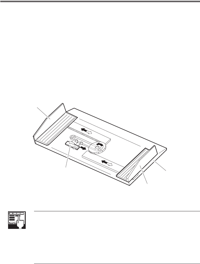
COPYRIGHT
©
2001 CANON INC. 2000 2000 2000 2000 CANON iR2200/iR2800/iR3300 REV.0 MAR. 2001
CHAPTER 5 PICK-UP/FEEDING SYSTEM
5-28 P
5.2 Identifying the Size of Paper in the Multifeeder
5.2.1 Detecting the Width of Paper
The width of paper is detected by a variable resistor operating in conjunction with the
movement of the slide guide. The slide guide is set when the user adjusts the multifeeder
tray to suit the paper placed on it.
5.2.2 Rear/Front Registration
The rear/front registration of the multifeeder may be adjusted by turning the screw on the
slide guide.
5.2.3 Identifying the Length of Paper
The length of paper is detected with reference to the period of time during which the pre-
registration paper sensor (PS10) remains ON while copies are being made. The maximum
size of paper is 432 × 279 mm (11×17).
F05-602-01
COPIER>ADJUST>CST-ADJ>MF-A4R
Use it to adjust the paper width basic value of A4R paper for the manual
feed tray.
COPIER>ADJUST>CSRT-ADJ>MF-A6R
Use it to adjust the paper width basic value of A6R for the manual feed tray.
COPIER>ADJUST>CST-ADJ>MF-A4
Use it to adjust the paper width basic value of A4 paper for the manual feed
tray.
Slide guide (rear)
Variable resistor
Slide guide (front)
Multifeeder tray
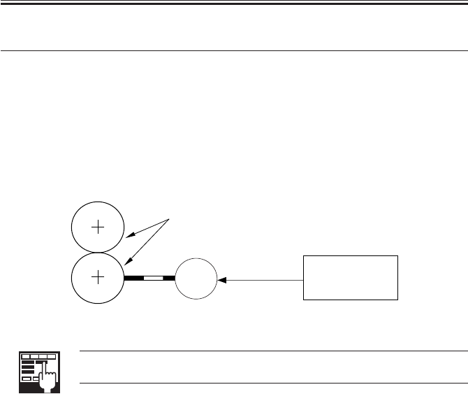
COPYRIGHT
©
2001 CANON INC. 2000 2000 2000 2000 CANON iR2200/iR2800/iR3300 REV.0 MAR. 2001
CHAPTER 5 PICK-UP/FEEDING SYSTEM
5-29 P
6 Controlling the Registration Roller
6.1 Outline
The registration roller is driven by the registration motor (M9) so that the paper and the
image on the photosensitive drum will match at a specific point.
The timing at which the registration roller rotates may be adjusted in service mode
(ADJUST>FEED-ADJ>REGIST).
6.2 Control System
F05-602-01
COPIER>ADJUST>FEED-ADJ>REGIST
Use it to adjust the timing at which the registration roller is started.
M9
Registration rollers
Registration
drive signal
J309
DC controller
PCB

COPYRIGHT
©
2001 CANON INC. 2000 2000 2000 2000 CANON iR2200/iR2800/iR3300 REV.0 MAR. 2001
CHAPTER 5 PICK-UP/FEEDING SYSTEM
5-30 P
7 Double-Sided Printing
7.1 Through-Path Operation
In this sequence of operations, paper after fixing is fed to the delivery assembly and then
to the duplex feeding assembly using the reversing flapper. the machine re-arranges the or-
der of images in its memory for printing.
As many as two sheets may exist at a time between the registration sensor and the duplex
paper sensor.
COPIER>ADJUST>FEED-ADJ>ADJ-REFE
Use it to adjust the image write start position in main scanning direction for
re-pickup. (-100 to 100 mm)
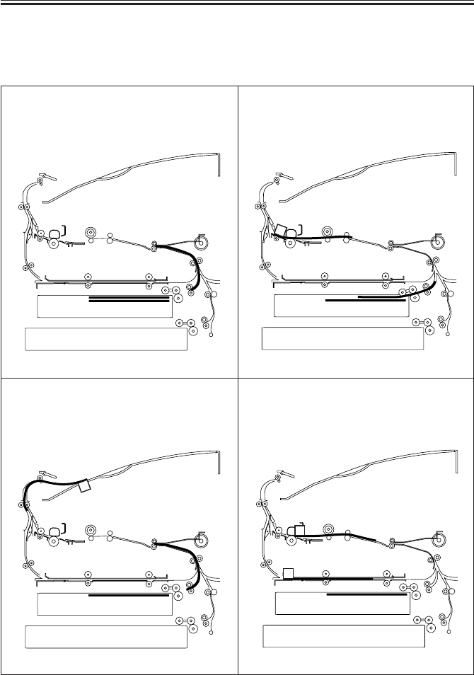
COPYRIGHT
©
2001 CANON INC. 2000 2000 2000 2000 CANON iR2200/iR2800/iR3300 REV.0 MAR. 2001
CHAPTER 5 PICK-UP/FEEDING SYSTEM
5-31 P
7.2 Outline of Operations
For instance, through-path operations take place as follows when one set of double-sided
prints are made of six originals:
F05-703-01
1) The 1st sheet is picked up from the cassette.
3) The 1st sheet is switched back in the deliv-
ery assembly, and is then sent to the duplex
feeding assembly.
2) The 2nd side is printed on the 1st sheet.
4) The 2nd sheet is picked up, and the 4th side
is printed.
2
2
2
4

COPYRIGHT
©
2001 CANON INC. 2000 2000 2000 2000 CANON iR2200/iR2800/iR3300 REV.0 MAR. 2001
CHAPTER 5 PICK-UP/FEEDING SYSTEM
5-32 P
F05-703-02
5) The 2nd sheet is switched back in the deliv-
ery assembly, and is then sent to the duplex
feeding assembly.
7) The 1st sheet is delivered.The 2nd sheet is
in the duplex feeding assembly.
6) The 1st side is printed on the back of the 1st
sheet.
8) The 3rd sheet is picked up, and the 6th side
is printed. After this operation, a series of
processes are repeated.
2
4
1
2
4
1
2
4
1
2
4
6
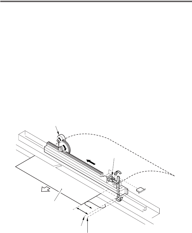
COPYRIGHT
©
2001 CANON INC. 2000 2000 2000 2000 CANON iR2200/iR2800/iR3300 REV.0 MAR. 2001
CHAPTER 5 PICK-UP/FEEDING SYSTEM
5-33 P
7.3 Detecting the Horizontal Registration Position
7.3.1 Outline
• In duplex printing, paper coming from the duplex feeding assembly is checked for hori-
zontal registration, and the detected displacement in rear/front direction is made up for
by adjusting the point of laser exposure.
Paper position: by duplex horizontal registration sensor (PS11)
Timing of detection: after duplex paper sensor (PS10) goes ON
Drive: by duplex horizontal registration motor (M3)
Position: by pulse from duplex horizontal registration motor
(1 pulse = about 0.16 mm)
Related service mode: COPIER>ADJUST>FEED-ADJ>ADJ-REFE
Related error code: E051 (home position not detected within specific time)
T05-703-01
F05-703-01
M3
PS11
Copy paper
10mm(approx.)
Detecting start position
Home position
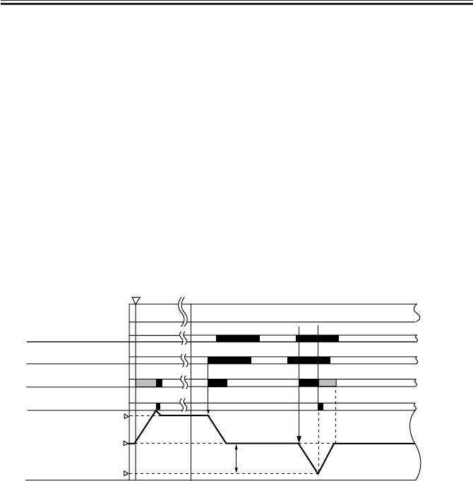
COPYRIGHT
©
2001 CANON INC. 2000 2000 2000 2000 CANON iR2200/iR2800/iR3300 REV.0 MAR. 2001
CHAPTER 5 PICK-UP/FEEDING SYSTEM
5-34 P
7.3.2 Operation
1) Timing of Detecting Home Position
When the main power switch is turned on, During jam recovery, When the front cover is
closed
2) Start Position
The detection start position is set at a point about 10 mm from the edge of paper whose
movement is ideal with reference to the data on the paper width collected from the slide
guide on the manual feed tray and the cassette size when the registration sensor goes ON.
3) Detectiong operation
When paper fed to the duplex feeding assembly reaches the registration roller, the hori-
zontal registration motor (M3) goes ON, and the duplex horizontal registration sensor
(PS11) starts paper edge detection. The detection takes place for each time a double-sided
print is made.
The detection of paper position is done with reference to the start position, and the dis-
placement from the actual paper position is identified with reference to the drive pulses from
the motor (1 pulse = about 0.16 mm).
*1: the position of the edge of paper differs depending on the size of paper, hence different SP.
HP: start position of the duplex horizontal sensor.
SP: detection start position of the duplex horizontal registration sensor.
F05-703-02
INTR/STBY
PRINT
H.P
S.P
*1
Registration motor
(M9)
Registration sensor
(PS10)
Duplex horizontal
registration motor(M3)
Duplex horizontal
registration sensor(PS11)
Duplex horizontal
registration sensor
(PS11) position
Paper edge
Main power switch ON
Reverse Reverse
Forward
Forward
10 mm(approx.)
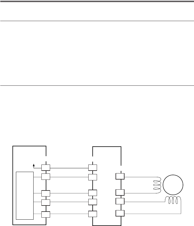
COPYRIGHT
©
2001 CANON INC. 2000 2000 2000 2000 CANON iR2200/iR2800/iR3300 REV.0 MAR. 2001
CHAPTER 5 PICK-UP/FEEDING SYSTEM
5-35 P
8 Controlling the Pickup Assembly Motor
8.1 Pickup Assembly Motor
The pickup assembly motor system consists of six stepping motors of 2-phase magnetic
excitation type.
Each motor is supplied with power by the motor driver PCB, and is turned on/off and ro-
tated clockwise or counterclockwise by pulse signals from the DC controller PCB.
T05-801-01 shows the motors used in the pickup assembly and F05-801-01 shows a
block diagram of the control circuit for the cassette 1/2 pickup motor:
Location Motor name Notation Error detection
Pickup system Cassette 1/2 pickup motor (M2) Jam occurred
Vertical path system Duplex motor (M6) Jam occurred
Duplex system Duplex registration motor (M3) E051
Others Registration moter (M9) Jam occurred
Delivery moter (M5) Jam occurred
T05-801-01
F05-801-01
Feeder driver
PCB
M2
A6
18
A7
J302
3
4
1
2
J1602
DC controller
PCB
PIO
(IC303)
A
A*
B
B*
A8
A9
13
12
J1601
11
10
+24V
A1

COPYRIGHT
©
2001 CANON INC. 2000 2000 2000 2000 CANON iR2200/iR2800/iR3300 REV.0 MAR. 2001
CHAPTER 5 PICK-UP/FEEDING SYSTEM
5-36 P
9 Disassembly and Assembly
The discussions that follow cover the machine’s mechanical characteristics and how to
disassemble/assemble the machine. Keep the following in mind whenever you work with the
machine:
1. The power plug must remain disconnected for safety when disassembling/assembling
the machine.
2. Unless otherwise noted, the machine may be assembled by reversing the steps used to
disassemble it.
3. The screws must be identified by type (length, diameter) and location.
4. The mounting screws used for the grounding wire and the varistors come with a washer,
which must not be left out when assembling the machine.
5. As a rule, the machine must not be operated with any of its parts removed.
6. The door switch or the main power switch must be turned off whenever the duplex unit
or the fixing/feeding unit must be slid out.
7. The toner must not be disposed of into fire to avid explosion.
8. Do not operate the machine without locking the feeding assembly in place to avoid dam-
age.
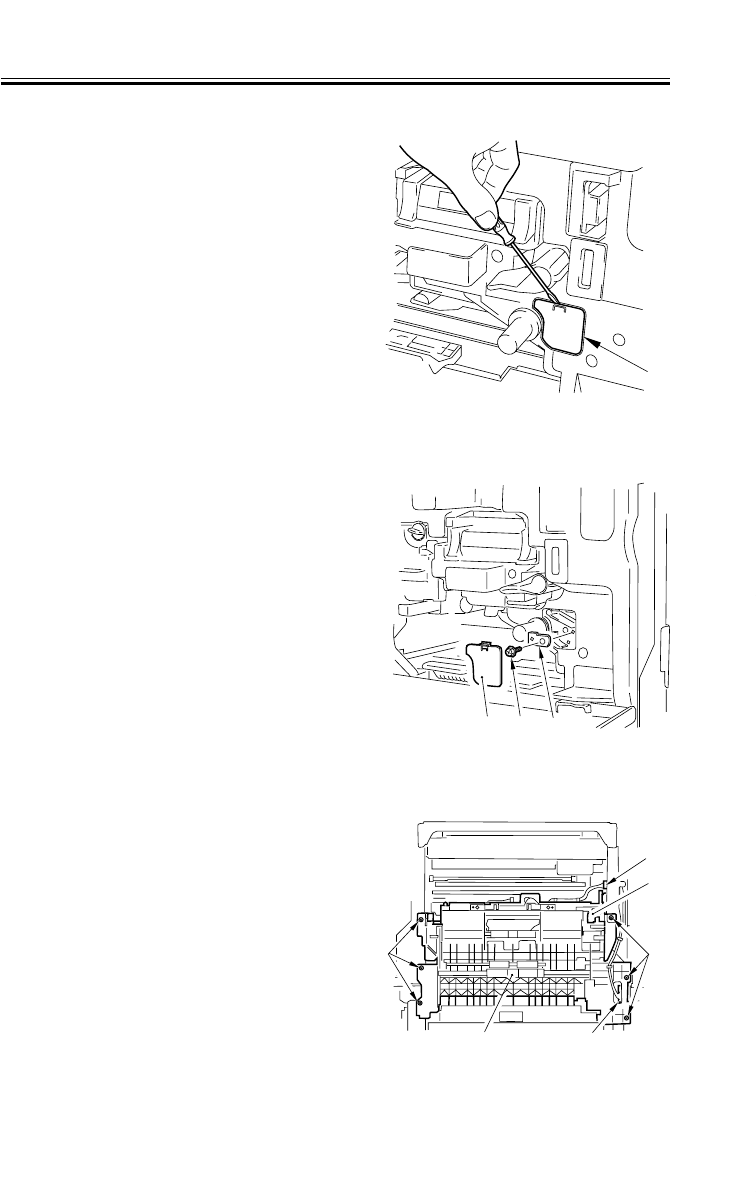
COPYRIGHT
©
2001 CANON INC. 2000 2000 2000 2000 CANON iR2200/iR2800/iR3300 REV.0 MAR. 2001
CHAPTER 5 PICK-UP/FEEDING SYSTEM
5-37 P
9.1 Pickup Assembly
9.1.1 Removing the Pickup Assembly
1) Remove the cassette 1/2.
2) Remove the multifeeder tray. (p. 5-42P)
3) Remove the pickup cover. (p. 5-43P)
4) Remove the right lower cover.
5) Fit a flat-bladed screwdriver, and re-
move the paper lint cleaning cover [1].
F05-901-01
6) Remove the screw [2], and detach the
positioning pin [3].
F05-901-02
7) Disconnect the two connectors [1].
8) Remove the seven screws [2], and re-
move the screw [3] from the right rear;
then, detach the pickup assembly [4].
F05-901-03
[1] [2] [3]
[1]
[1]
[1]
[2]
[2]
[4]
[3]
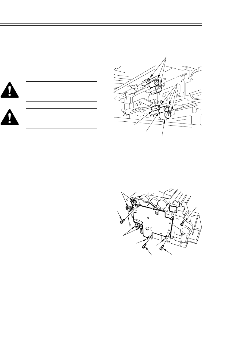
COPYRIGHT
©
2001 CANON INC. 2000 2000 2000 2000 CANON iR2200/iR2800/iR3300 REV.0 MAR. 2001
CHAPTER 5 PICK-UP/FEEDING SYSTEM
5-38 P
9.1.2 Removing the Pickup/Feeding/Separation Rollers
1) Remove the cassette 1/2.
2) Pick the tab [4] of each, and detach the
pickup roller [1], feeding roller [2], and
separation roller [3] in the axial direc-
tion.
When removing the roller, take
care not to soil it with the grease
used on the rail assembly.
When mounting the roller, be
sure to fit it until a click is
heard.
F05-901-04
9.1.3 Removing the Pickup Solenoid
1) Remove the pickup assembly. (p. 5-
37P)
2) Disconnect the connector [1].
3) Remove the screw [2], and detach
pickup solenoid [3].
F05-901-05
[3]
[3]
[2]
[2]
[1]
[1]
[1] [1]
[4]
[1]
[2] [3]
[4]
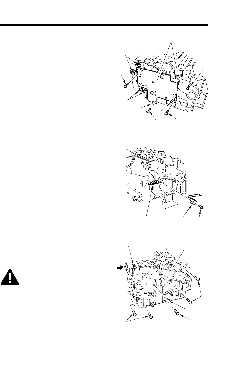
COPYRIGHT
©
2001 CANON INC. 2000 2000 2000 2000 CANON iR2200/iR2800/iR3300 REV.0 MAR. 2001
CHAPTER 5 PICK-UP/FEEDING SYSTEM
5-39 P
9.1.4 Removing the Frame Lid
1) Remove the pickup solenoid. (p. 5-38P)
2) Remove the four screws [1], and dis-
connect the four connectors [2].
3) While spreading the two claws [3], de-
tach the pickup PCB [4].
F05-901-06
4) Remove the coil spring [1].
5) Remove the screw [2], and detach the
leaf spring [3].
F05-901-07
6) Remove the five screws [1]; then, while
freeing the two claws [2], detach the
frame lid [3].
When mounting, detach the two
bushings [4] from the frame lid
[3]; fix the frame lid using the
claw [2]; mount back the bush-
ings; then, check to see if the
harness is routed correctly by
looking through the opening in
area A.
F05-901-08
[3]
[3]
[2]
[4]
[2]
[1]
[1]
[1] [1]
[3]
[1] [2]
[2] [3]
[1]
[2]
[1]
[1]
[4]
[4]
A
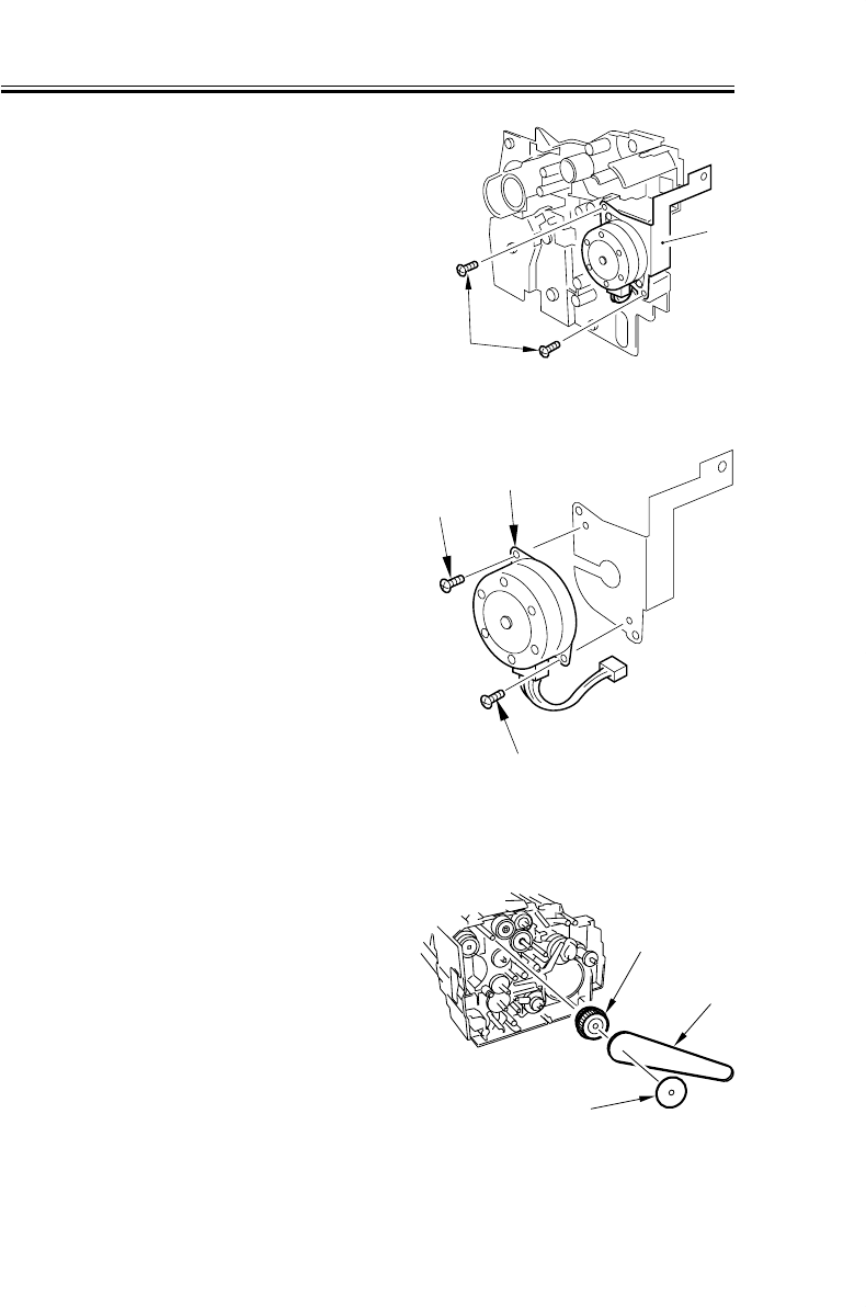
COPYRIGHT
©
2001 CANON INC. 2000 2000 2000 2000 CANON iR2200/iR2800/iR3300 REV.0 MAR. 2001
CHAPTER 5 PICK-UP/FEEDING SYSTEM
5-40 P
9.1.5 Removing the Pickup Motor
1) Remove the frame lid. (p.5-39P)
2) Remove the two screws [1], and detach
the pickup unit [2].
F05-901-09
3) Remove the two screws [1], and detach
the pickup motor [2].
F05-901-10
9.1.6 Remove the Vertical Path Cultch
1) Remove the frame lid. (p. 5-39P)
2) Remove the flange [1], belt [2], and
gear [3].
F05-901-11
[2]
[1]
[2]
[1]
[1]
[3]
[2]
[1]

COPYRIGHT
©
2001 CANON INC. 2000 2000 2000 2000 CANON iR2200/iR2800/iR3300 REV.0 MAR. 2001
CHAPTER 5 PICK-UP/FEEDING SYSTEM
5-41 P
3) Remove the grip ring [1], and detach
the vertical path clutch [2].
F05-901-12
9.1.7 Removing the Horizontal Registration Sensor Shift Motor
1) Remove the pickup assembly. (p. 5-
37P)
2) Disconnect the two connectors [1].
3) Remove the two screws [2], and detach
the horizontal registration unit. [3].
F05-901-13
4) Remove the two screws [1], and detach
the horizontal registration sensor shift
motor [2].
F05-901-14
[1]
[2]
[3]
[1]
[2]
[2]
[1]
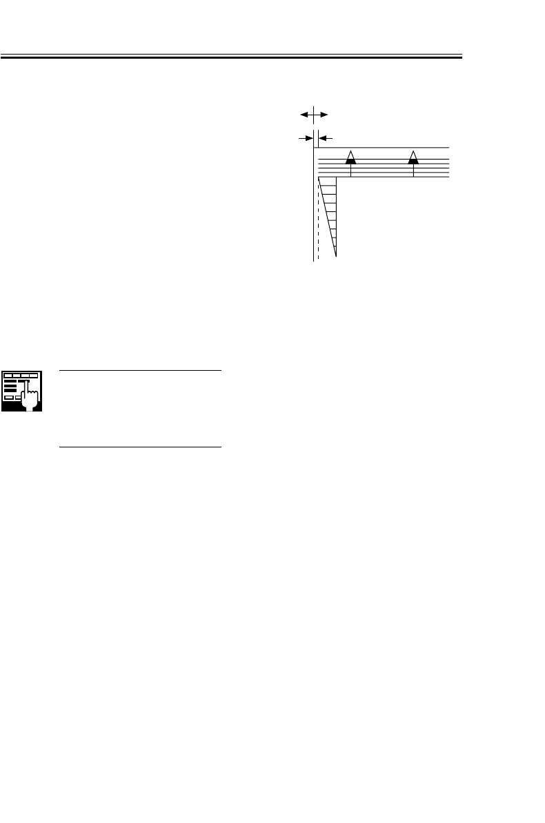
COPYRIGHT
©
2001 CANON INC. 2000 2000 2000 2000 CANON iR2200/iR2800/iR3300 REV.0 MAR. 2001
CHAPTER 5 PICK-UP/FEEDING SYSTEM
5-42 P
9.1.8 Checking the Image Rear Front Position
Make copies in Direct, and check to make
sure that the margin along the image front is
2.5 ± 1.5 mm for all sheets from all sources
of paper. Otherwise, adjust the registration.
(See item 9.1.9.)
F05-901-15
9.1.9 Adjusting the Cassette Rear Front Registration
Execute 'image read start position adjust-
ment' in service mode.
COPIER>FUNCTION>C1-
ADJ-Y/C2-ADJ-Y/C3-ADJ-Y/
C4-ADJ-Y
Use it to adjust the image read
start position.
If correction in service mode fails, make
the following adjustments.
0
2
4
6
8
10
(-) (+)
2.5±1.5mm
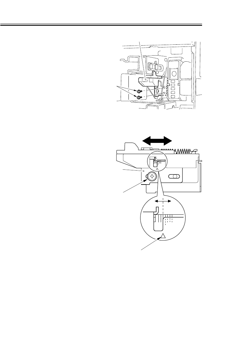
COPYRIGHT
©
2001 CANON INC. 2000 2000 2000 2000 CANON iR2200/iR2800/iR3300 REV.0 MAR. 2001
CHAPTER 5 PICK-UP/FEEDING SYSTEM
5-43 P
1) Remove the cassette.
2) Remove the two screws [1], and detach
the horizontal registration base assem-
bly [2].
F05-901-16
3) Loosen the screw [1], and adjust the
horizontal registration plate [2].
When making adjustments, try to match
the arrow [3] against the index (each
graduation being about 1 mm).
F05-901-17
[1]
[2]
[2]
[1]
[3]
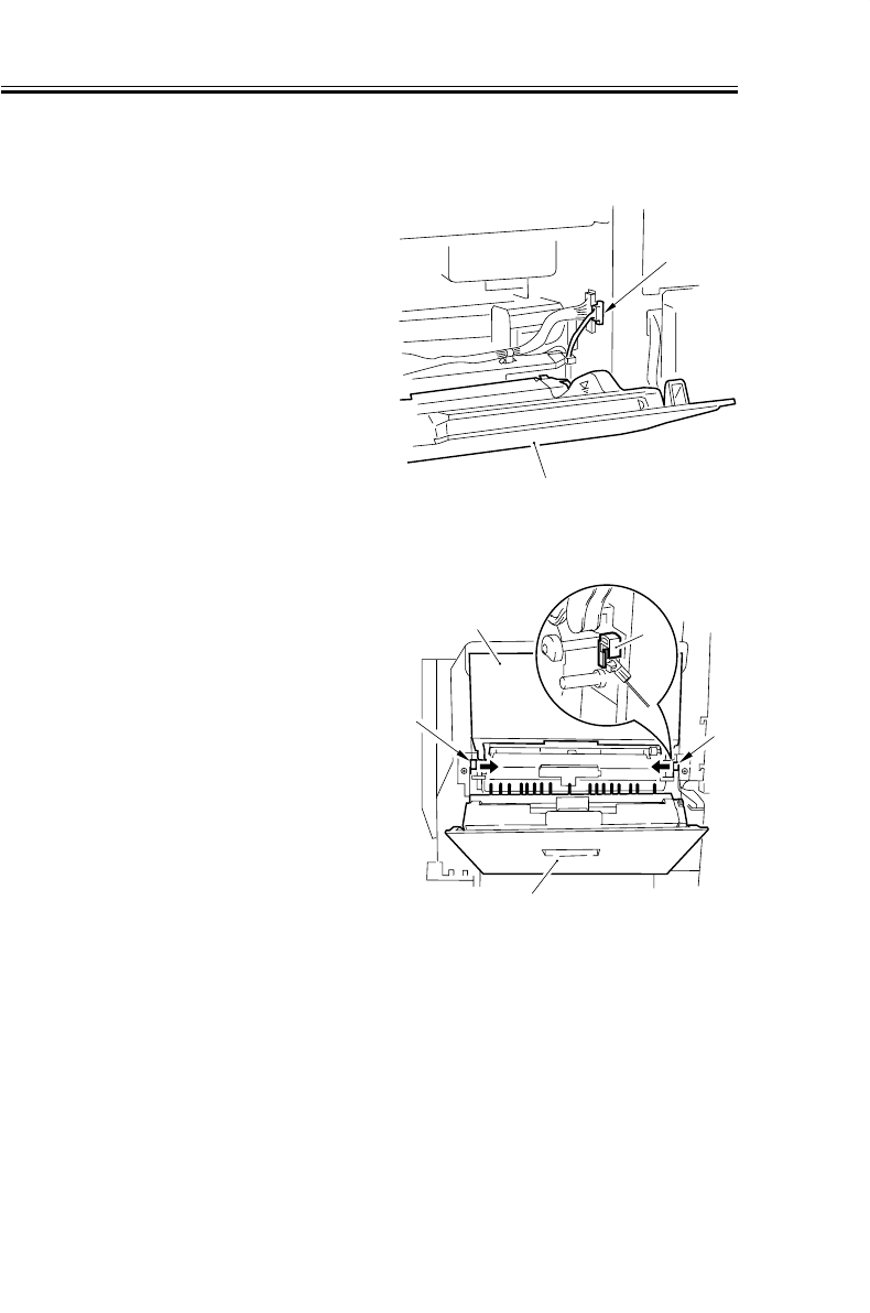
COPYRIGHT
©
2001 CANON INC. 2000 2000 2000 2000 CANON iR2200/iR2800/iR3300 REV.0 MAR. 2001
CHAPTER 5 PICK-UP/FEEDING SYSTEM
5-44 P
9.2 Multifeeder Tray Assembly
9.2.1 Removing the Multifeeder Tray Assembly
1) Open the multifeeder tray [1], and re-
move the following: delivery tray (2
screws), right front cover (2 screws),
right rear cover (5 screws), right inside
cover (2 screws).
2) Disconnect the connector [2].
F05-902-01
3) Close the multifeeder tray [1], and open
the pickup cover [2]; then, detach the
member [3] on the left and the right. (At
this time, the multifeeder tray is not
locked in place; work while supporting
it with your hand.)
F05-902-02
4) Open the multifeeder tray once again,
and detach it to the right.
[1]
[2]
[2]
[1]
[3]
[3]
[3]
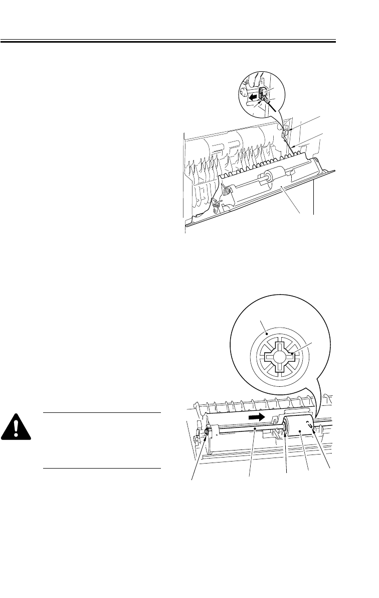
COPYRIGHT
©
2001 CANON INC. 2000 2000 2000 2000 CANON iR2200/iR2800/iR3300 REV.0 MAR. 2001
CHAPTER 5 PICK-UP/FEEDING SYSTEM
5-45 P
9.2.2 Removing the Pickup Cover
1) Open the pickup cover [1].
2) Remove the member [2] from the rear.
3) Free the cable [4] from the hook [3].
4) Remove the pickup cover [1].
F05-902-03
9.2.3 Removing the Multifeeder Tray Pickup Roller
1) Remove the pickup cover. (See item
9.2.2.)
2) Remove the snap-on bushing [1].
3) While taking care not to deform the
grounding plate at the rear of the roller
shaft [2], shift the roller shaft [2] in the
direction of the arrow.
4) Remove the stop ring [3], and detach
the multifeeder tray pickup roller [5]
while taking care not to drop the paral-
lel pin [4] at the rear.
When mounting, be sure that
the pin notch (cross-shaped) in
the collar [6] of the multifeeder
tray pickup roller [5] is toward
the rear.
F05-902-04
[2]
[4]
[1]
[2]
[4]
[3]
[1] [2] [3] [5] [4]
[6]
[5]
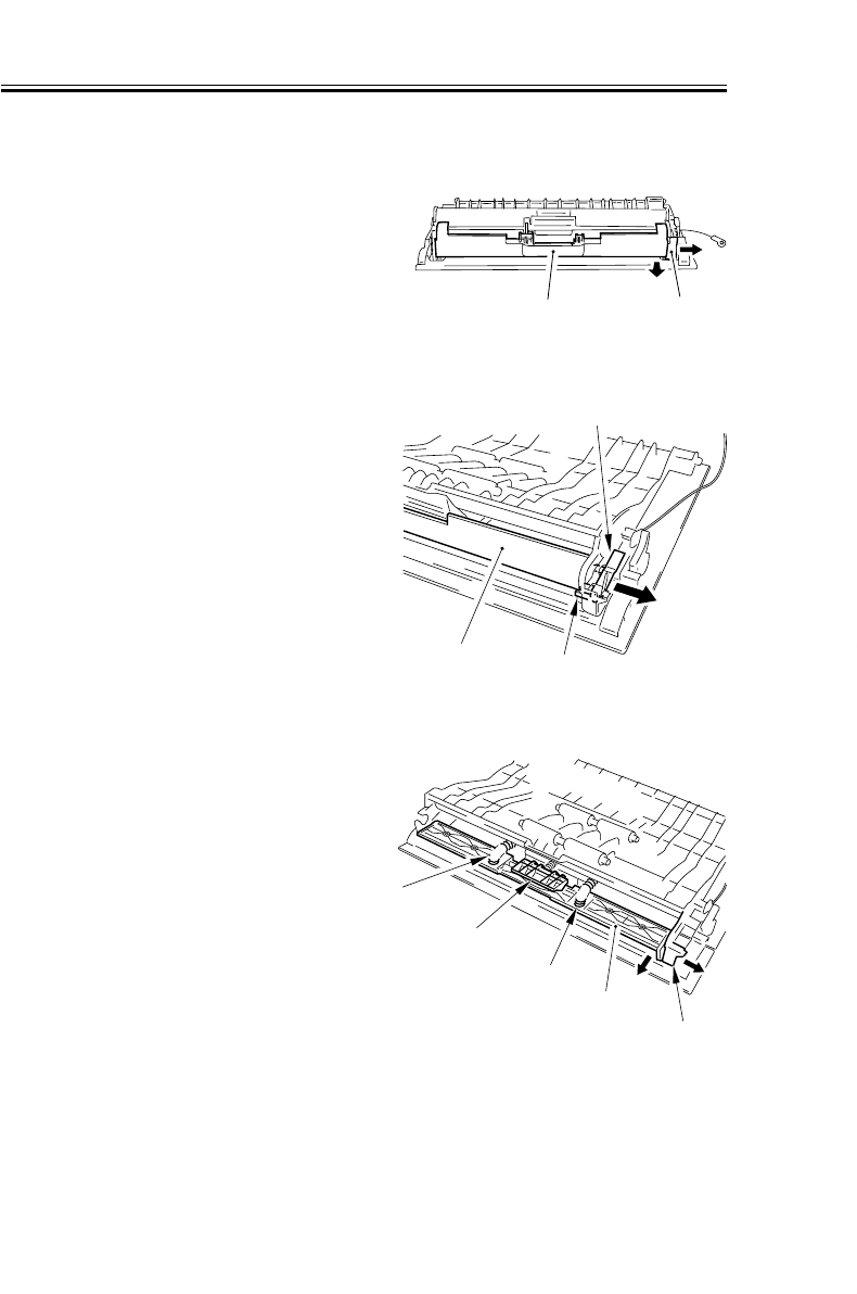
COPYRIGHT
©
2001 CANON INC. 2000 2000 2000 2000 CANON iR2200/iR2800/iR3300 REV.0 MAR. 2001
CHAPTER 5 PICK-UP/FEEDING SYSTEM
5-46 P
9.2.4 Removing the Separation Pad
1) Remove the multifeeder tray pickup
roller. (p. 5-45P)
2) While butting the end [1] of the pickup
cover in the direction of A, pull the rear
of the separation pad over [2] in the di-
rection of B to detach.
F05-902-05
3) While holding down the multifeeder in-
termediate retaining plate [1] so that it
will not open, remove the lever claw as-
sembly [2] and detach the lever [3].
F05-902-06
4) Open the multifeeder intermediate re-
taining plate [2] so that the two springs
[1] will not spring out.
5) Remove the two springs [1].
6) While pushing the end [3] of the pickup
cover in the direction of A, pull the
multifeeder intermediate retaining plate
[2] in the direction of B to detach.
7) Remove the separation pad [4].
F05-902-07
[2] [1]
B
A
[1] [2]
[3]
[3]
[2]
[1]
[4]
[1]
A
B
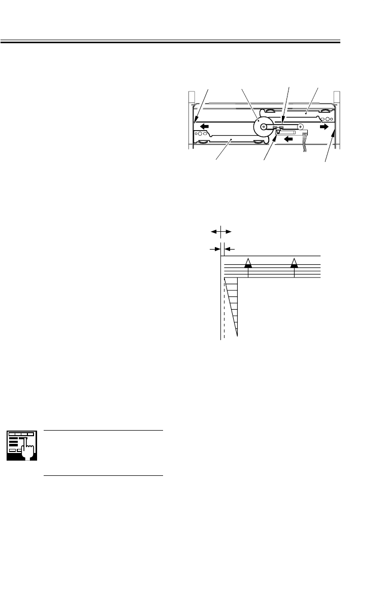
COPYRIGHT
©
2001 CANON INC. 2000 2000 2000 2000 CANON iR2200/iR2800/iR3300 REV.0 MAR. 2001
CHAPTER 5 PICK-UP/FEEDING SYSTEM
5-47 P
9.2.5 Attaching the Timing Belt of the Multifeeder Tray
1) Butt the two rack plates [1] of the
multifeeder tray against both ends (area
A).
2) Move the slide volume [2] in the direc-
tion of B, and attach the timing belt [3]
to the pulley [4].
F05-902-08
9.2.6 Checking the Image Rear Front Position
Make copies (from the Multifeeder Tray)
in Direct, and check to make sure that the
margin along the image front is 2.5 ± 1.5
mm. Otherwise, adjust the registration. (See
item 9.2.7)
F05-902-09
9.2.7 Adjusting the Registration for the Multifeeder Rear Front
Execute ‘image read start position adjust-
ment’ in service mode.
COPIER>FUNCTION>MF-
ADJ-Y
Use it to adjust the image read
start position.
If correction in service mode fails, make
the following adjustments.
B
A
A
[1]
[1]
[2]
[3]
[4]
0
2
4
6
8
10
(-) (+)
2.5±1.5mm
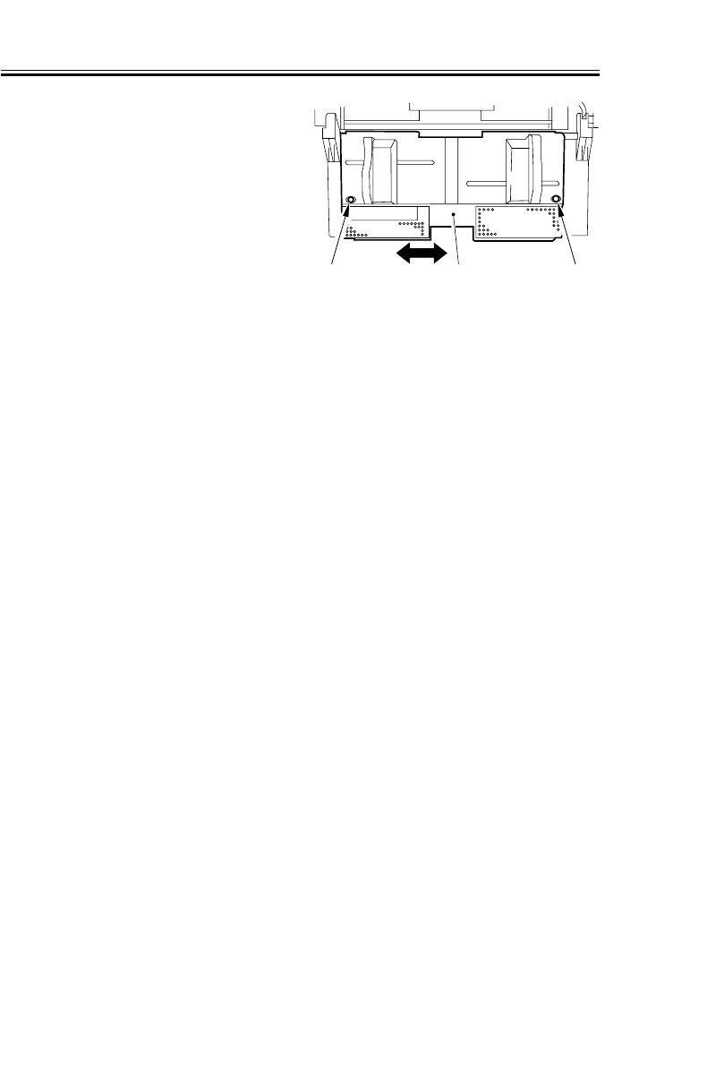
COPYRIGHT
©
2001 CANON INC. 2000 2000 2000 2000 CANON iR2200/iR2800/iR3300 REV.0 MAR. 2001
CHAPTER 5 PICK-UP/FEEDING SYSTEM
5-48 P
[2] [1][1]
1) Open the multifeeder tray.
2) Loosen the two screws [1], and move
the side guide plate unit [2] back and
forth to adjust.
F05-902-10
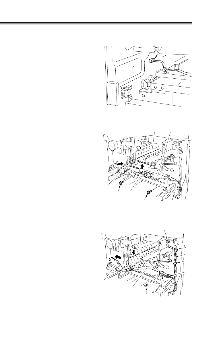
COPYRIGHT
©
2001 CANON INC. 2000 2000 2000 2000 CANON iR2200/iR2800/iR3300 REV.0 MAR. 2001
CHAPTER 5 PICK-UP/FEEDING SYSTEM
5-49 P
9.3 Feeding Assembly
9.3.1 Removing the Feeding Assembly
1) Remove the cassette 1/2.
2) Remove the pickup assembly. (p. 5-
37P)
3) Remove the delivery cover. (p. 6-12P)
4) Disconnect the concoctor [1] of the
lower feeding assembly from the left.
F05-903-01
5) Remove the inside cover. (p. 7-14P)
6) Mount the feeding locking lever [1]
temporarily, and lock the feeding as-
sembly [2] in place.
7) Remove the pin [3], and detach the du-
plex grip [4].
8) Remove the two screws [5], and detach
the lower feeding assembly [6] from be-
low.
F05-903-02
9) Turn the feeding locking lever [1] to re-
lease the feeding assembly [2].
10) Disconnect the connector [3], and de-
tach the sensor cable [4] from the three
wire saddles [5] and the hinge [6].
11) Remove the screw [7], and detach the
hinge pin [6].
12) While taking care not to trip them on
the flapper [8] and the like, detach the
feeding assembly [2] to the front.
F05-903-03
[1]
[1]
[5]
[4]
[3] [2] [6]
[5]
[1]
[2]
[6]
[5]
[5]
[4]
[5]
[7]
[3]
[8]

COPYRIGHT
©
2001 CANON INC. 2000 2000 2000 2000 CANON iR2200/iR2800/iR3300 REV.0 MAR. 2001
CHAPTER 5 PICK-UP/FEEDING SYSTEM
5-50 P
9.3.2 Mounting the Feeding Assembly
1) Fit the hinge [2] of the feeding assem-
bly in the hinge hole [3] in the frame
(rear) of the host machine.
F05-903-04
[1]
[3] [2]
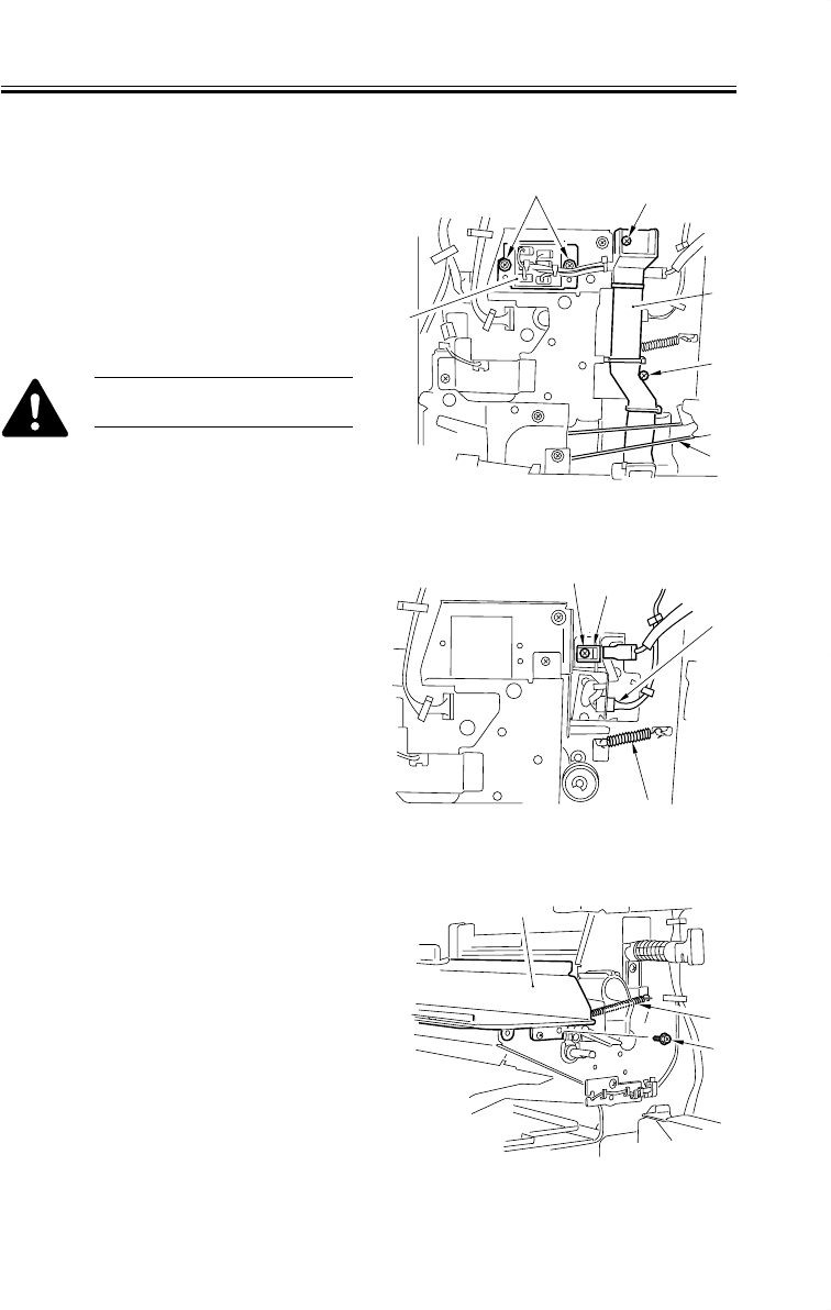
COPYRIGHT
©
2001 CANON INC. 2000 2000 2000 2000 CANON iR2200/iR2800/iR3300 REV.0 MAR. 2001
CHAPTER 5 PICK-UP/FEEDING SYSTEM
5-51 P
9.4 Registration Roller Assembly
9.4.1 Removing the Registration Roller
1) Remove the front inside cover (6
screws).
2) Remove the controller box unit. (p. 7-
19P)
3) Remove the two screws [1] each (front,
rear), and detach the front cover switch
[2] and the harness guide [3].
Take care not to damage the belt
[4].
F05-904-01
4) Disconnect the connector [1].
5) Remove the screws [2], and detach the
terminal [3].
6) Remove the spring [4].
F05-904-02
7) Remove the spring [1] from the front.
8) Remove the stepped screw [2], and de-
tach the developing assembly base [3].
F05-904-03
[1] [1]
[1]
[3]
[2]
[4]
[1]
[4]
[2] [3]
[1]
[3]
[2]
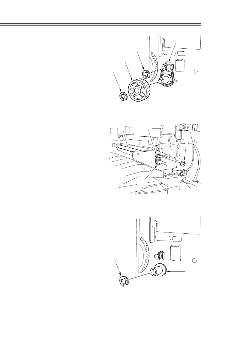
COPYRIGHT
©
2001 CANON INC. 2000 2000 2000 2000 CANON iR2200/iR2800/iR3300 REV.0 MAR. 2001
CHAPTER 5 PICK-UP/FEEDING SYSTEM
5-52 P
9) Remove the E-ring [1] at the rear, and
detach the gear [2]
10) Remove the spring [3].
11) Remove the E-ring [4], and detach the
bushing.
F05-904-04
12) Remove the spring [1] at the front.
13) Remove the E-ring [2], and detach the
bushing [3].
14) Remove the upper registration roller [4].
F05-904-05
15) Remove the E-ring [1] at the rear, and
detach the busing [2].
F05-904-06
[1]
[3]
[5]
[4]
[2]
[1]
[3]
[4]
[2]
[1]
[2]

COPYRIGHT
©
2001 CANON INC. 2000 2000 2000 2000 CANON iR2200/iR2800/iR3300 REV.0 MAR. 2001
CHAPTER 5 PICK-UP/FEEDING SYSTEM
5-53 P
16) Remove the E-ring [1] at the front, and
detach the bushing [2].
17) Remove the lower registration roller [3].
F05-904-07
[1]
[3]
[2]

COPYRIGHT
©
2001 CANON INC. 2000 2000 2000 2000 CANON iR2200/iR2800/iR3300 REV.0 MAR. 2001
CHAPTER 6
FIXING SYSTEM

COPYRIGHT
©
2001 CANON INC. 2000 2000 2000 2000 CANON iR2200/iR2800/iR3300 REV.0 MAR. 2001
CHAPTER 6 FIXING SYSTEM
6-1 P
1 Outline of Operations
1.1 Outline
The fixing system has the following major functions:
Item Description
Method of fixing SURF method
Fixing heater Main heater: flat
Sub heater: flat (integrated to main heater)
Control temperature Varies according to selected mode
Temperature detection [1] Main thermistor (temperature control, error detection)
[2] Sub thermistor (error detection)
[3] Thermal switch (error detection)
Fixing temperature control [1] Power-on sequence
[2] Country-specific sequence
[3] Site temperature-specific sequence
Method of cleaning Cleaning roller
Error detection [1] Temperature error detection by thermistor
[2] Overheating detection by thermal switch
Fixing film Equipped with rotation detection mechanism
T06-101-01
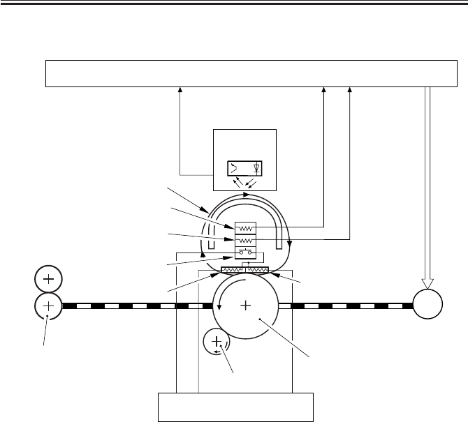
COPYRIGHT
©
2001 CANON INC. 2000 2000 2000 2000 CANON iR2200/iR2800/iR3300 REV.0 MAR. 2001
CHAPTER 6 FIXING SYSTEM
6-2 P
The following diagram shows the major components of the fixing system:
F06-101-01
M4
Main thermistor signal (M_TH2)
Fixing film signal
(FILM_ROT_D)
DC controller PCB
Main power supply PCB
Fixing film
sensor(PS26)
Fixing motor
Fixing lower roller
Cleaning roller
Fixing film
Fixing main heater (H1)
Thermal switch (TP1)
Main thermistor (TH1)
Sub thermistor signal (S_TH2)
Fixing sub heater (H2)
Sub thermistor (TH2)
Fixing delivery roller

COPYRIGHT
©
2001 CANON INC. 2000 2000 2000 2000 CANON iR2200/iR2800/iR3300 REV.0 MAR. 2001
CHAPTER 6 FIXING SYSTEM
6-3 P
F06-101-02
Item Notation Description
Fixing lower roller Pressure roller
Fixing motor M4 24VDC
Main/sub heater H1, H2 230V model: 637 W
120V model: 607 W
100V model: 621 W
Main thermistor TH1 Temperature control, error detection
Sub thermistor TH2 Error detection
Thermal switch TP1 Operating temperature: 250 ± 7°C
Fixing film sensor PS26 Rotation detection; reflection type sensor
T06-101-02
Fixing main heater (H1)
Main thermistor (TH1)
Sub thermistor (TH2)
Fixing sub heater (H2)
Fixing film sensor (PS26)
Fixing film
Fixing lower roller
Cleaning roller
Thermal switch (TP1)
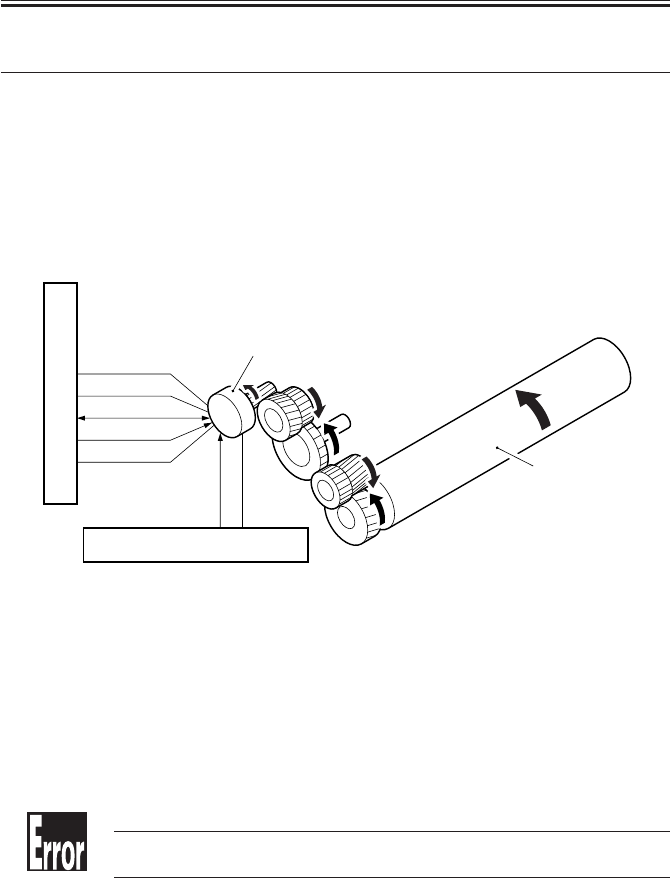
COPYRIGHT
©
2001 CANON INC. 2000 2000 2000 2000 CANON iR2200/iR2800/iR3300 REV.0 MAR. 2001
CHAPTER 6 FIXING SYSTEM
6-4 P
2 Fixing Drive System
2.1 Outline
The fixing drive system involves the following control mechanisms:
1. Fixing roller drive control
2. Fixing film rotation speed detection/control
2.2 Controlling the Fixing Roller Drive
F06-202-01 shows the construction of the control system used for the fixing roller drive:
The following signals are used:
[1] Fixing motor drive signal (FSAR_ON):
when ‘1’, the motor goes ON.
[2] Fixing motor drive lock signal (FSAR_CLK):
when the rotation of the fixing motor reaches a specific speed, ‘0’.
[3] Fixing motor low-speed drive signal (FSAR_SPEED):
when the rotation of the fixing motor is controlled to 1/4, ‘1’.
F06-202-01
E014 (fixing motor speed error)
Indicates that the drive lock signal cannot be detected with 1.3 sec after the
fixing motor drive signal (M4) is generated.
FSAR_ON*
FSAR_LOCK*
N.C
FSRM_CLK
FSRM_SPEED*
M4
24V
GND
DC controller PCB
Fixing motor
Fixing lower roller
Main power supply PCB
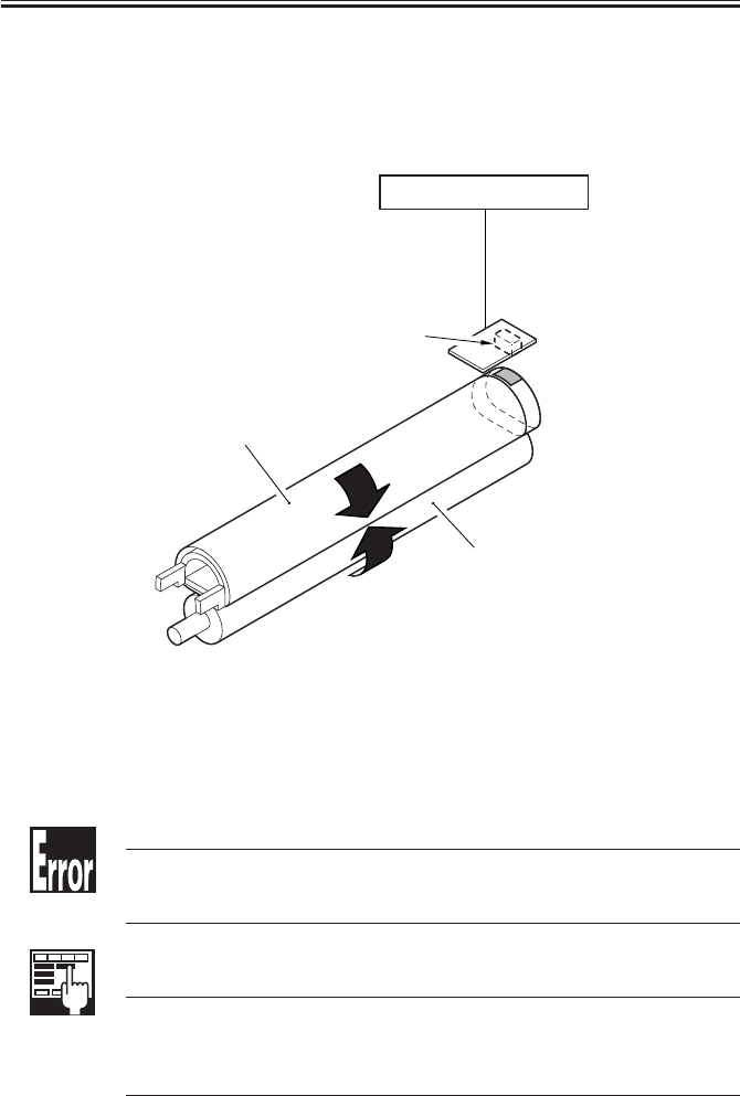
COPYRIGHT
©
2001 CANON INC. 2000 2000 2000 2000 CANON iR2200/iR2800/iR3300 REV.0 MAR. 2001
CHAPTER 6 FIXING SYSTEM
6-5 P
2.3 Controlling the Fixing Film Speed
F06-202-02 shows the construction of the control system used for the fixing film speed;
the speed of rotation is controlled according to the changes in the output of the fixing film
sensor (PS26).
The following signal is used:
[1] Film rotation detection signal (FSAR_ROT_D): when the fixing film is rotating, alter-
nately ‘1’ and ‘0’.
F06-202-02
E007 (fixing film rotation error)
Indicates that the film rotation detection signal cannot be detected for 6 sec
or more when the reading of the main thermistor is 100°C or higher and, in
addition, the fixing motor is rotating.
COPIER>ADJUST>FIXING>FX-FL-SP
COPIER>ADJUST>FIXING>FX-FL-TH
Use it to adjust the rotation speed of the fixing film. Blurry images caused
by a fault in the fixing assembly can at times be corrected. (Blurry images
can occur 400-some millimeters of the trailing edge.) This mode may also
be used to adjust the reproduction ratio in feed direction.
FILM_ROT_D
Fixing film
Fixing lower roller
Fixing film sensor (PS26)
DC controller PCB
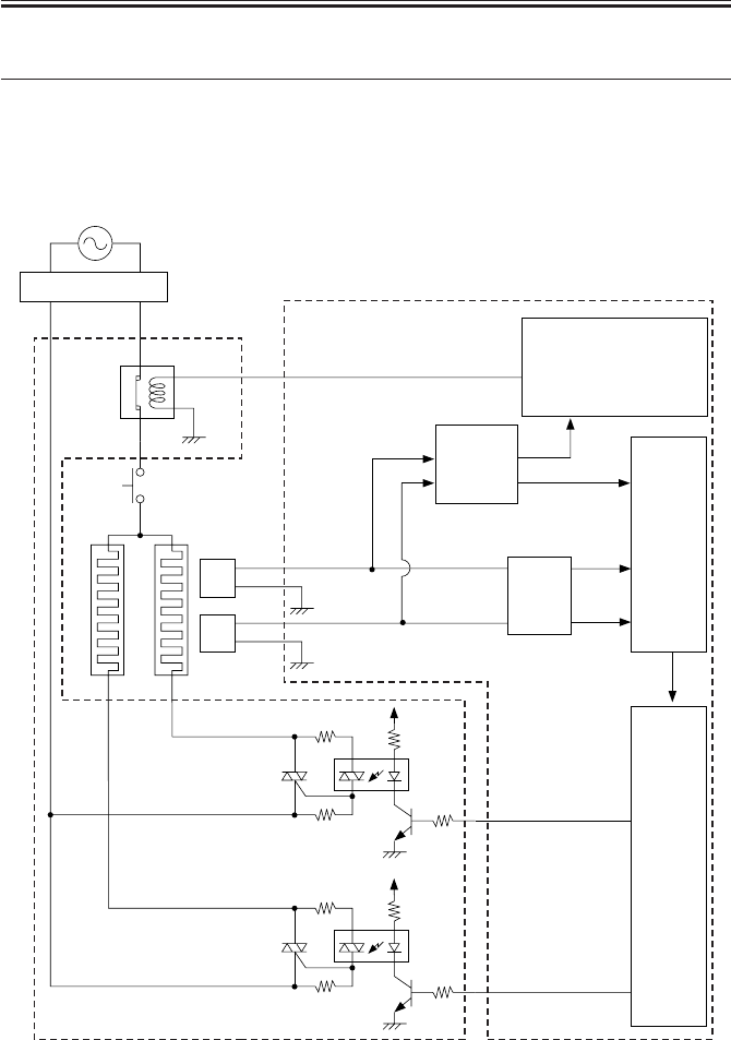
COPYRIGHT
©
2001 CANON INC. 2000 2000 2000 2000 CANON iR2200/iR2800/iR3300 REV.0 MAR. 2001
CHAPTER 6 FIXING SYSTEM
6-6 P
3 Controlling the Fixing Temperature
3.1 Outline
The fixing temperature is controlled for the following:
[1] Fixing heater temperature
[2] Thermistor error detection
F06-301-01
+5V
+5V
+5V
TH1
TH2
IC334
IC300
Fixing main
thermistor
Fixing sub
thermistor
Heater relay circuit
A/D converter
(200V)
Thermal switch
(TP1)
Fixing main heater (H1)
Fixing sub heater
(H2)
Switch PCB
RelayRL1
DC controller PCB
Main power supply PCB
High-
temperature
detection
circuit

COPYRIGHT
©
2001 CANON INC. 2000 2000 2000 2000 CANON iR2200/iR2800/iR3300 REV.0 MAR. 2001
CHAPTER 6 FIXING SYSTEM
6-7 P
3.2 Temperature Control
The machine’s fixing temperature is controlled using the following means:
State Item Description
Normal [1] Power-on sequence Used with pre-heating control if the reading of
the main thermistor (TH1) is 100°C or lower dur-
ing recovery from sleep mode/power-on/controll
panel input/document detection.
[2] Start-up sequence Used at time of starting copying operation.
[3] Normal temperature control Used to set a temperature to suit the selected
sequence paper type/size according to the thermal
condition of the fixing assembly.
[4] Sheet-to-sheet control Used to lower the fixing temperature between
sequence sheets fed continuously.
[5] Edge overheating sequence Used to prevent overheating on the ends of the
heater otherwise caused by continuously fed
small-size sheets. (The operation will slow
down.)
Service mode [7]
Fixing temperature switch-over
The target temperature for fixing control is
Upon selection
COPIER>OPTION>BODY> switched.
FIX-TEMP 1: -10°C
2: -6°C
3: -3°C
4: +3°C
5: +6°C
6: +10°C
7: +15°C
T06-302-01
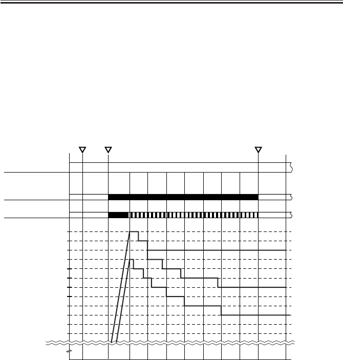
COPYRIGHT
©
2001 CANON INC. 2000 2000 2000 2000 CANON iR2200/iR2800/iR3300 REV.0 MAR. 2001
CHAPTER 6 FIXING SYSTEM
6-8 P
3.2.1 Fixing Temperature Control
The machine is equipped with the following modes to suit the type of paper used: plain
paper, thick paper, bond paper, and envelope/postcard (each with a specific control table).
A start point of temperature control on the control table is determined based on the tem-
perature of the fixing lower roller considered against the following factors:
a. Reading of main thermistor (TH1)
b. History of jobs (intervals, quantity)
F06-302-01 shows a sample control table:
F06-302-01
Wait indication RedGreen Green
Fixing heater
(M4)
Main heater
(H1)
Sub heater
(H2)
STBY STBY
Bond paper
mode
Thick paper
mode
Plain paper
mode
Lower←Fixing lower temperature estimate→Higher
Main
power
switch ON Print
start End
195˚C
190˚C
185˚C
200˚C
180˚C
175˚C
170˚C
165˚C
205˚C
210˚C
215˚C
220˚C

COPYRIGHT
©
2001 CANON INC. 2000 2000 2000 2000 CANON iR2200/iR2800/iR3300 REV.0 MAR. 2001
CHAPTER 6 FIXING SYSTEM
6-9 P
3.3 Detecting Errors
The machine checks for the following in relation to its fixing temperature control mecha-
nism:
1. Temperature control error by main thermistor (TH1)
2. Temperature control error by sub thermistor (TH2)
The following signals are used in association with errors:
[1] Fixing temperature detection signal 1 (M_TH2): voltage output according to the reading
of the main thermistor.
[2] Fixing temperature detection signal 2 (S_TH2): voltage according to the reading of the
sub thermistor.
[3] Main heater drive signal: when ‘1’, the main heater goes ON.
[4] Sub heater drive signal: when ‘2’, the sub heater goes ON.
[5] Relay drive signal (RLY_1): when ‘1’, the relay (RL1) on the main power supply PCB
goes ON.
F06-303-01
+5V
+5V
+5V
TH1
Fixing main
thermistor
TH2
Fixing sub
thermistor
Heater relay circuit
A/D converter
(200V)
Thermal switch
(TP1)
Fixing main heater (H1)
Fixing sub heater (H2)
IC300
IC334
Switch PCB
RelayRL1
DC control PCB
Main power
supply PCB
[1]
[5]
[2]
[3]
[4]
High-
temperature
detection
circuit

COPYRIGHT
©
2001 CANON INC. 2000 2000 2000 2000 CANON iR2200/iR2800/iR3300 REV.0 MAR. 2001
CHAPTER 6 FIXING SYSTEM
6-10 P
E000
The main thermistor (TH1) has poor contact or an open circuit. The thermal
switch (TP1) has an open circuit. The main /sub heater has an open circuit.
The main power supply PCB is faulty. The DC control PCB is faulty. The
door switch is faulty.
E001
The main thermistor (TH1) has a short circuit. The sub thermistor (TH2)
has a short circuit. The main power supply PCB is faulty. The DC controller
PCB is faulty?
E002
The main thermistor (TH1) has poor contact or an open circuit. The thermal
switch has an open circuit (TP1). The fixing heater has an open circuit. The
AC driver PCB is faulty. The DC controller PCB is faulty. The door switch
is faulty.
E003
The main thermistor (TH1) has poor contact or an open circuit. The thermal
switch has an open circuit (TP1). The fixing heater has an open circuit. The
main power supply PCB is faulty. The DC controller PCB is faulty. The
door switch is faulty.
E007
The fixing motor (M4) is faulty. The fixing film sensor (P26) is faulty.
If a code from E000 through E003 is indicated, the indication will not be
reset even when the main power switch is turned off and then on, requiring
clearing of the error in service mode
(COPIER>FUNCTION>CLEAR>ERR).
If E001 or E003 is detected within 3sec after the front cover switch is iden-
tified as being open/closed, however, the error indication will be reset when
the main power switch is turned off and then on. This is to prevent the user
from placing a service call in response to an error detected while the switch
operation is not stable (as occurring immediately after the switch is turned
on/off).

COPYRIGHT
©
2001 CANON INC. 2000 2000 2000 2000 CANON iR2200/iR2800/iR3300 REV.0 MAR. 2001
CHAPTER 6 FIXING SYSTEM
6-11 P
4 Disassembly and Assembly
The discussions that follow cover the machine’s mechanical characteristics and how to
disassemble/assemble the machine. Keep the following in mind whenever you work with the
machine:
1. The power plug must remain disconnected for safety when disassembling/assembling
the machine.
2. Unless otherwise noted, the machine may be assembled by reversing the steps used to
disassemble it.
3. The screws must be identified by type (length, diameter) and location.
4. The mounting screws used for the grounding wire and the varistors come with a washer,
which must not be left out when assembling the machine.
5. As a rule, the machine must not be operated with any of its parts removed.
6. The door switch or the main power switch must be turned off whenever the duplex
unit or the fixing/feeding unit must be slid out.
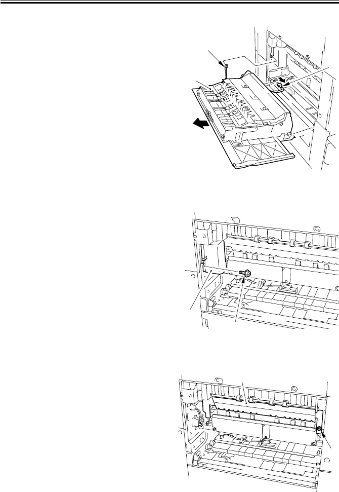
COPYRIGHT
©
2001 CANON INC. 2000 2000 2000 2000 CANON iR2200/iR2800/iR3300 REV.0 MAR. 2001
CHAPTER 6 FIXING SYSTEM
6-12 P
4.1 Fixing Assembly
4.1.1 Removing the Delivery Cover
1) Open the delivery cover [1].
2) Remove the cable [2].
3) Shift farther down the delivery cover
[1], and disconnect the connector [3];
then, detach the delivery cover.
F06-401-01
4.1.2 Removing the Riser Guide
1) Remove the delivery cover. (See item
4.1.1.)
2) Remove the screw [1], and detach the
connector cover [2].
F06-401-02
3) Remove the screw [1], and detach the
riser guide [2].
F06-401-03
[1]
[3]
[2]
[1]
[2]
[1]
[2]
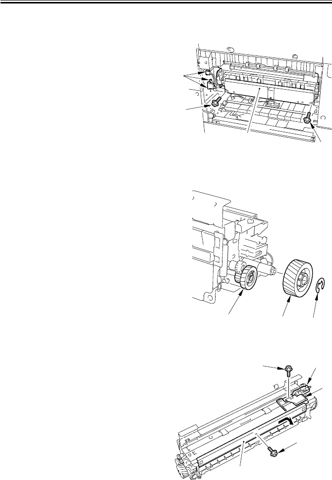
COPYRIGHT
©
2001 CANON INC. 2000 2000 2000 2000 CANON iR2200/iR2800/iR3300 REV.0 MAR. 2001
CHAPTER 6 FIXING SYSTEM
6-13 P
4.1.3 Removing the Fixing Assembly
1) Remove the riser guide. (p. 6-12P)
2) Check to see if the feeding assembly is
locked in position.
3) Disconnect the three connectors [1].
4) Remove the two screws [2], and detach
the fixing assembly [3].
F06-401-04
4.1.4 Removing the Fixing Stepped Gear
1) Remove the fixing assembly. (See item
4.1.3.)
2) Remove the E-ring [1], and detach the
gear [2].
3) Free the claw, and detach the fixing
stepped gear [3].
F06-401-05
4.1.5 Removing the Fixing Film Unit
1) Remove the fixing assembly. (See item
4.1.3.)
2) Remove the screw [1], and slide the in-
let upper guide [2] to the rear to re-
move.
3) Remove the screw [3], and detach the
sensor unit [4] and the sensor unit guide
[5].
F06-401-06
[2]
[3] [2]
[1]
[1]
[2]
[3]
[3] [5]
[4]
[1]
[2]
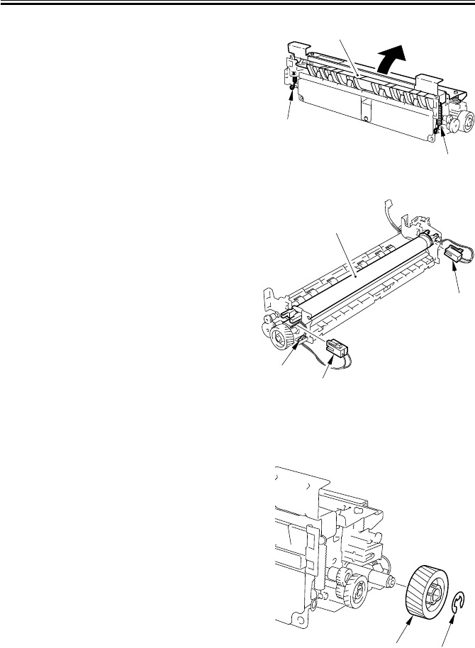
COPYRIGHT
©
2001 CANON INC. 2000 2000 2000 2000 CANON iR2200/iR2800/iR3300 REV.0 MAR. 2001
CHAPTER 6 FIXING SYSTEM
6-14 P
4) Remove the two springs [1], and open
the front of the fixing assembly top [2]
to detach.
F06-401-07
5) Disconnect that front connector [1]
(brown) and the rear connector [2]
(black).
6) Disconnect the connector [3], and re-
move the fixing film unit [4].
F06-401-08
4.1.6 Removing the Roller Bushing, Conducting Rubber, and Fixing Roller
1) Remove the fixing assembly. (p. 6-13P)
2) Remove the E-ring [1], and detach the
gear [2].
F06-401-09
3) Remove the fixing film unit. (p. 6-13P)
[2]
[1]
[1]
[3]
[2]
[1]
[4]
[1]
[2]
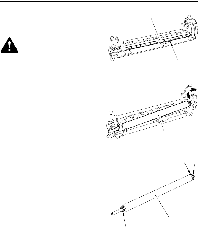
COPYRIGHT
©
2001 CANON INC. 2000 2000 2000 2000 CANON iR2200/iR2800/iR3300 REV.0 MAR. 2001
CHAPTER 6 FIXING SYSTEM
6-15 P
4) Free the claw [2] of the inlet lower
guide [1], and slide it to the rear to re-
move.
Take care not to damage the fix-
ing roller. When mounting,
avoid pushing it against the fix-
ing roller.
F06-401-10
5) Lift the rear of the fixing roller assem-
bly [1], and slide it to the rear to re-
move.
F06-401-11
6) Detach the two roller bushings [2] from
the fixing roller [1].
7) Remove the conducting rubber [3].
F06-401-12
[1]
[2]
[1]
[3]
[1]
[2]
[2]

COPYRIGHT
©
2001 CANON INC. 2000 2000 2000 2000 CANON iR2200/iR2800/iR3300 REV.0 MAR. 2001
CHAPTER 6 FIXING SYSTEM
6-16 P
4.1.7 Removing the Cleaning Roller Unit
1) Remove the screw [1], and detach the
outlet guide support plate [2].
2) Remove the cleaning roller unit [3].
F06-401-13
4.1.8 Removing the Lower Guide Ribs
1) Remove the fixing assembly. (p. 6-13P)
2) Remove the cleaning roller unit. (See
item 4.1.7.)
3) Push the claw [3] of the five lower
guide ribs [1] from the bottom of the
lower guide [2] to free and detach.
After mounting it, look from
below to make sure that the
claw [3] is positioned correctly.
F06-401-14
[1] [2] [3]
[3] [2]
[1]
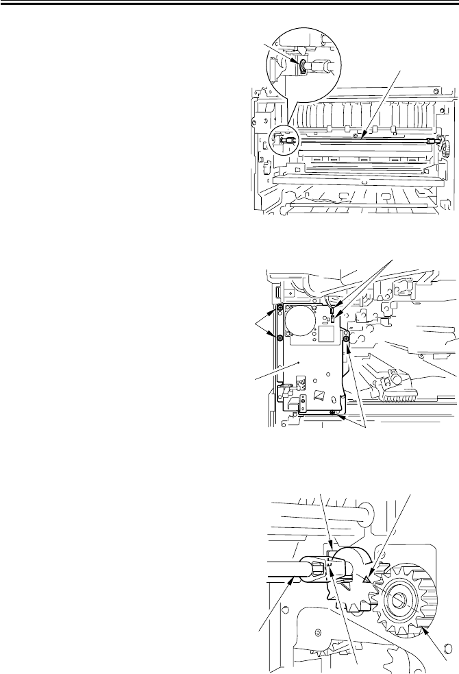
COPYRIGHT
©
2001 CANON INC. 2000 2000 2000 2000 CANON iR2200/iR2800/iR3300 REV.0 MAR. 2001
CHAPTER 6 FIXING SYSTEM
6-17 P
4.1.9 Removing the Fixing Drive Unit
1) Remove the fixing assembly. (p. 6-13P)
2) Check to see that the feeding assembly
is locked in place.
3) Free the claw of the bushing [1], and
slide it to the front.
4) Remove the locking cam unit [2].
F06-401-15
5) Remove the inside cover. (p. 7-14P)
6) Check to see if the feeding assembly is
released.
7) Disconnect the two connectors [1].
8) Remove the four screws [2], and detach
the fixing drive unit [3].
F06-401-16
4.1.10 Mounting the Locking Cam Unit
1) Check to see if the feeding assembly is
locked in place.
2) Match the arrow of the gear of the lock-
ing cam unit [1] against the middle of
the gear [3] of the fixing drive unit (e.i.,
where the rear [4] of the gear of the
locking cam unit is in contact with the
cut-up [5] of the frame).
F06-401-17
[1]
[2]
[3]
[2]
[1]
[2]
[4] [3]
[1]
[5] [2]

COPYRIGHT
©
2001 CANON INC. 2000 2000 2000 2000 CANON iR2200/iR2800/iR3300 REV.0 MAR. 2001
CHAPTER 7
EXTERNALS AND CONTROLS
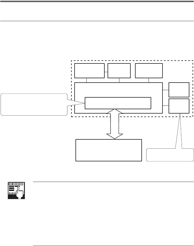
COPYRIGHT
©
2001 CANON INC. 2000 2000 2000 2000 CANON iR2200/iR2800/iR3300 REV.0 MAR. 2001
CHAPTER 7 EXTERNALS AND CONTROLS
7-1 P
1 Control Panel
1.1 Outline
The machine’s control panel consists of the following PCBs and a touch panel (LCD)
with a resolution of 320 × 240 dots.
F07-101-01
COPIER>FUNCTION>PANEL>LCD-CHK
Use it to check the LCD for missing dots.
COPIER>FUNCTION>PANEL>LED-CHK
Use it to start a check on the activation of the LEDs in the control panel.
COPIER>FUNCTION>PANEL>LED-OFF
Use it to end a check on the activation of the LEDs in the control panel.
COPIER>FUNCTION>PANEL>KEY-CHK
Use it to start a check on key inputs.
COPIER>FUNCTION>PANEL>TOUCHCHK
Use it to check the coordinates on the touch panel.
CPU
Control
panel inverter
PCB LCD PCB Control
panel PCB
(keys, LEDs)
Control panel
power switch
PCB
LCD contrast
adjustment
PCB
Control panel CPU PCB
Control panel
• Monitors key input
(keypad, function keys)
• Controls buzzer sound
• Controls control panel LEDs
Adjusts the contrast
of the LCD.
Main controller PCB

COPYRIGHT
©
2001 CANON INC. 2000 2000 2000 2000 CANON iR2200/iR2800/iR3300 REV.0 MAR. 2001
CHAPTER 7 EXTERNALS AND CONTROLS
7-2 P
2 Fans
2.1 Arrangement, Functions, and Error Codes
The names and functions of and the error codes associated with the machine’s fans are as
follows:
Notation
Name Function 2-speed control Error code
(voltage)
FM1 Developing Cools the developing Yes (24/12 V) E805-0001
assembly fan assembly, Cools the
laser scanner
FM2 Fixing fan Cools the fixing assembly, Yes (24/12 V) E805-0002
Cools the drum unit
FM3 Electric unit fan Cools the electric unit Yes (24/12 V) E805-0003
FM4 Curl reducing fan 1 Prevents curling of paper No (24 V) E805-0004
FM5 Curl reducing fan 2 Prevents curling of paper No (24 V) E805-0005
The curl reducing fans 1 and 2 are enabled or disabled in service mode:
COPIER>OPTION>BODY>DECRL-FN>
T07-201-01
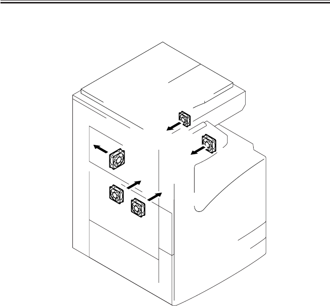
COPYRIGHT
©
2001 CANON INC. 2000 2000 2000 2000 CANON iR2200/iR2800/iR3300 REV.0 MAR. 2001
CHAPTER 7 EXTERNALS AND CONTROLS
7-3 P
The arrangement of the fans and the directions of current are as follows:
F07-201-01
FM1
FM2
FM3
FM4
FM5
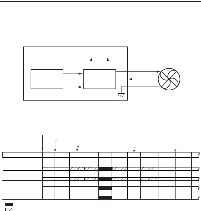
COPYRIGHT
©
2001 CANON INC. 2000 2000 2000 2000 CANON iR2200/iR2800/iR3300 REV.0 MAR. 2001
CHAPTER 7 EXTERNALS AND CONTROLS
7-4 P
2.2 Operation
2.2.1 2-Speed Control
Some of the machine’s fans are controlled for two speeds (F07-202-01); the voltage
switching PCB of each fan changes its output voltage to switch between speeds.
F07-202-01
2.2.2 Sequence of Operations
F07-202-02
Voltage
switching
circuit
CPU
DC controller PCB
Fan
24V or 12V
Clock signal
Full speed
signal
24V 12V
Half speed
signal
Control panel switch ON
Main power switch ON
Control panel
switch OFF
Developing fan
(FM1)
Electrical unit fan
(FM3)
Fixing assembly
(FM2)
Curl reducing fan 1/2
(FM4/FM5)
Warm-up
Printer unit state
Standby
Printing
Low-power
Door open
Jam
Print end
: full speed.
: half speed or at rest; if the polygon mirror motor (M10) is ON, half speed; if OFF, at rest.
+1
*1: Rotates for 30 sec after the leading edge sensor goes ON during printing; if the sensor goes ON for
a second time during the 30-sec period, rotates for another 30 sec.
Initial multiple rotation

COPYRIGHT
©
2001 CANON INC. 2000 2000 2000 2000 CANON iR2200/iR2800/iR3300 REV.0 MAR. 2001
CHAPTER 7 EXTERNALS AND CONTROLS
7-5 P
3 Power Supply
3.1 Power Supply
3.1.1 Outline
The machine’s power supply is controlled by the DC power supply PCB; the PCBs and
associated components are shown in T07-301-01, and the distribution of power is shown in
F07-301-01.
Name Description
Main power supply PCB • Generates DC power from AC power
• Protects against overcurrent
Composite power supply PCB • Generates high voltage
Options PCB • Supplies power to side paper deck, finisher
Switch PCB (SW1/SW2) • Turns on/off main power supply PCB (SW1), Turns
on/off cassette heater, mirror heater, lens heater (SW2)
Door switch (SW3) • Detects state of door (open/closed), Cuts AC power to
fixing heater, Cuts 24V power to main motor, fixing
motor, composite power supply PCB
Thermistor power supply PCB (200 V) • Supplies power to thermsitor
Leakage breaker • Cuts power in response to error
T07-301-01
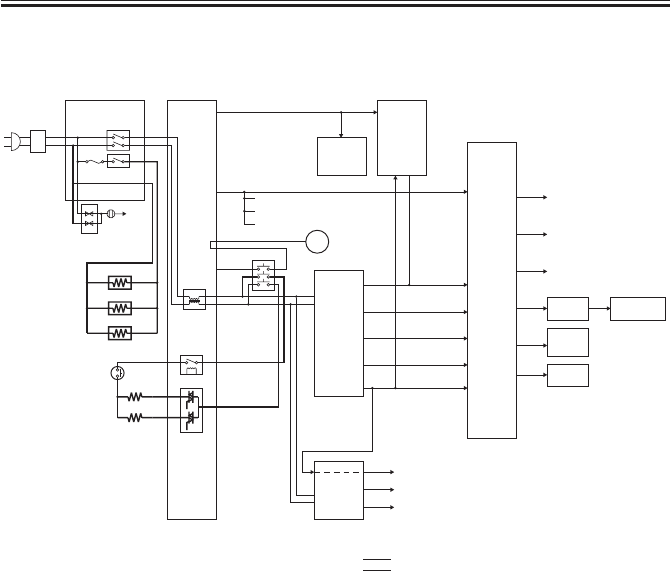
COPYRIGHT
©
2001 CANON INC. 2000 2000 2000 2000 CANON iR2200/iR2800/iR3300 REV.0 MAR. 2001
CHAPTER 7 EXTERNALS AND CONTROLS
7-6 P
The machine distributes power as follows:
F07-301-01
Leakage
breaker Switch PCB
SW1
SW2
Arrestor
ground
Arrestor PCB
(100V)
Cassette heater
Mirror heater
Lens heater
Filter
assembly
Main heater
Sub heater
RL1
Triac
Main power
supply PCB
DC
controller
PCB
Composite
power
supply
PCB
Reader
controller
PCB
ADF
24VU2
5VA
24VA1
24VA2
3VA1
(non-all night)
3VA2
(non-all night)
3VB (all-night)
24VU3
13V
5VA
5VA
5VA
5VA
5VA
13V
24VU1_SW
M
Main motor
Fixing motor
Options
power
supply
PCB
Side paper deck
Side paper deck
:
DC power supply
:
AC power supply
Finisher
Control panel
Inverter
BD
PCB
5VA HD
Sensors
Fans (half speed)
Clutches
Solenoids
Fans
Pickup PCB
Laser scanner
Cassette pedestal
Pre-exposure lamp
24VU3
SW3
24VU1
THSW
ADF
reader assembly
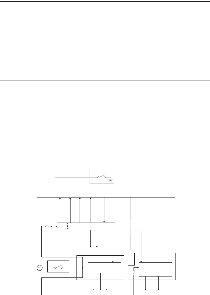
COPYRIGHT
©
2001 CANON INC. 2000 2000 2000 2000 CANON iR2200/iR2800/iR3300 REV.0 MAR. 2001
CHAPTER 7 EXTERNALS AND CONTROLS
7-7 P
3.1.2 Power Outputs
The machine’s power outputs are controlled by the main power switch (SW1) and the
control panel power switch (SW826), or signals from the printer board.
The following table shows the state of power supply from each power supply PCB in rela-
tion to combinations of the states of the main power switch and the control panel power
switch and the signals from the printer board:
T07-301-02
*1: If the environment switch (SW2) is ON, the cassette heater, mirror heater, and lens
heater are supplied with power.
F07-301-02
Main power
switch (SW1)
OFF*1
ON
ON
Control panel power
switch (SW826) or Signals
form printer/fax board
OFF
OFF
ON
Power output from
main power supply
PCB
No
No
All
Power output from
composite power
supply PCB
No
3VB
All
Power output from
accessories power
supply PCB
No
No
All
Main controller PCB
FU1
F3501
AC/DC converter
AC/DC
converter
5VA
24VU2 13VU
24VA1
24VA2
24VU1
24VU3
AC/DC
converter
3VB
(all-night)
3VA1
(non-all night)
3VA2
(non-all night)
5V
RMT1
RMT2
MPON
APON
Composite power
supply PCB
Accessories
power supply PCB
Main power supply PCB
Main power stitch
Switch PCB
SW1
UI_SOFT_SW*
Control panel PCB
Control panel switch
SW826

COPYRIGHT
©
2001 CANON INC. 2000 2000 2000 2000 CANON iR2200/iR2800/iR3300 REV.0 MAR. 2001
CHAPTER 7 EXTERNALS AND CONTROLS
7-8 P
3.2 Rated Outputs of the Main Power Supply PCB
Output 24VU1 24VU1-SW 24VU2 24VU3
Connector No. J200-1 J202-1 J203-2 J204-1
J203-1 J202-3 J204-3
J202-5 J204-7
J200-3*1 J204-8
J204-9
J206-2
Output voltage ± 5 %*2
tolerance
Rated output voltage 24V
Rated output current 9.0A
Overcurrent protection 5.5 to 8.0A
activation setting *1: input.
*2: +7% or -5%, depending on output current.
T07-302-01
3.3 Rated Output of the Composite Power Supply PCB
Output 3VA1 3VA2 3VB 5V 13VU
(non-all night) (non-all night) (all-night)
Connector No.
J121-4 J121-1 J121-11 J122-1 J126-2
J121-5 J121-2 J121-12 J122-2 J126-3
J122-3 J121-3 J121-13 J124-9 J126-5
J122-4 J124-10 J126-7
Output voltage
+2%, -4% ± 2% +3%, -4% -
tolerance
Rated output 3.4V 3.4V 5.1V 12.5 to 17.0V
voltage
Rated output 3.4V 1.9A 4.7A 0.11A
curren
Overcurrent
5.0 to 8.0A 5.0 to 8.0A 5.0 to 8.0A 1.0 to 8.0A
protection
activation setting.
T07-303-01
Note: The above assumes that the AC input is between 85 and 135 V for the 100/120V model, and
between 187 and 264 V for the 230V model.

COPYRIGHT
©
2001 CANON INC. 2000 2000 2000 2000 CANON iR2200/iR2800/iR3300 REV.0 MAR. 2001
CHAPTER 7 EXTERNALS AND CONTROLS
7-9 P
3.4 Rated Outputs of the Accessories Power Supply PCB
Output 24VA1 24VA2
Connector No. J703-2 J702-1
J704-6 J702-4
Output voltage tolerance +7%, -5%
Rated output voltage 24V
Rated output current 5.5A
Overcurrent protection 5.5 to 8.0A
activation setting
T07-304-01
Note: The above assumes that the AC input is between 85 and 135 V for the 100/120V model, and
between 187 and 264 V for the 230V model.

COPYRIGHT
©
2001 CANON INC. 2000 2000 2000 2000 CANON iR2200/iR2800/iR3300 REV.0 MAR. 2001
CHAPTER 7 EXTERNALS AND CONTROLS
7-10 P
3.5 Protective Functions
The machine’s each power supply PCB is equipped with an overcurrent protection circuit
designed to cut off the output of each power supply when they go ON.
While the signals RMT1 and RMT2 from the main controller PCB are used to turn on the
output of each power supply PCB, if 3VB stops from the composite power supply PCB be-
cause of a fault in the high-violate output or melting of the fuse, all outputs of power will be
cut.

COPYRIGHT
©
2001 CANON INC. 2000 2000 2000 2000 CANON iR2200/iR2800/iR3300 REV.0 MAR. 2001
CHAPTER 7 EXTERNALS AND CONTROLS
7-11 P
4 Others
4.1 Silent Mode
In silent mode, the drive of the laser scanner motor during standby is stopped for a spe-
cific period of time* after the start of standby to reduce the machine’s operating noise.
*The length may be changed in user mode.

COPYRIGHT
©
2001 CANON INC. 2000 2000 2000 2000 CANON iR2200/iR2800/iR3300 REV.0 MAR. 2001
CHAPTER 7 EXTERNALS AND CONTROLS
7-12 P
5 Disassembly and Assembly
The discussions that follow cover the machine’s mechanical characteristics and how to
disassemble/assemble the machine. Keep the following in mind whenever you work with the
machine:
1. The power plug must remain disconnected for safety when disassembling/assembling
the machine.
2. Unless otherwise noted, the machine may be assembled by reversing the steps used to
disassemble it.
3. The screws must be identified by type (length, diameter) and location.
4. The mounting screws used for the grounding wire and the varistors come with a washer,
which must not be left out when assembling the machine.
5. As a rule, the machine must not be operated with any of its parts removed.
6. The door switch or the main power switch must be turned off whenever the duplex unit
or the fixing/feeding unit must be slid out.
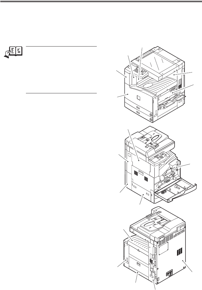
COPYRIGHT
©
2001 CANON INC. 2000 2000 2000 2000 CANON iR2200/iR2800/iR3300 REV.0 MAR. 2001
CHAPTER 7 EXTERNALS AND CONTROLS
7-13 P
5.1 External Covers
Remove the covers as needed when
cleaning, checking, or repairing the inside
of the machine.
REF.
Those covers that can be de-
tached by mere removal of
mounting screws are left out of
the discussions. Unless other-
wise noted, the number in pa-
rentheses indicates the number
of mounting screws used.
[1] Support cover (1 screw)
[2] Support the right cover (1 screw)
[3] Left rear cover
[4] Rear cover (4 screws)
[5] Front cover (2 L-shaped pins)
[6] Delivery tray (2 screws)
[7] Inside cover (6 screws)
[8] Right front cover (2 screws)
[9] Right lower cover (not in Cassette
Feeding Unit-W1)
[10]Right rear cover (5 screws)
[11]Left upper cover (2; not in Finisher-J1
or Inner 2Way Tray-A1)
[12]Left lower cover (1 screw)
[13]Left rear cover (1 screw)
[14]Waste toner case cover (1 screw)
[15]Rear cover (7 screws)
[16]Right inside cover (7 screws)
F07-501-01
[1]
[2]
[3]
[4]
[5]
[6]
[7]
[8]
[9]
[10]
[11]
[12]
[13]
[15]
[14]
[16]
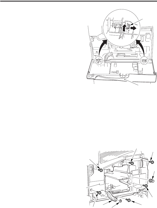
COPYRIGHT
©
2001 CANON INC. 2000 2000 2000 2000 CANON iR2200/iR2800/iR3300 REV.0 MAR. 2001
CHAPTER 7 EXTERNALS AND CONTROLS
7-14 P
5.1.1 Removing the Front Cover
1) Open the front cover [1], and shift up
the L-shaped pin [2] with your finger.
2) Shift the L-shaped pin [2] to the right to
detach the front cover [1].
F07-501-02
5.1.2 Removing the Inside Cover
1) Remove the front cover. (See item
5.1.1.)
2) Remove the drum unit. (p. 4-28P)
3) Remove the developing assembly. (p. 4-
33P)
4) Remove the cassette 1 (topmost cas-
sette).
5) Remove the registration roller knob [1].
6) Remove the grip ring [2], and detach
the feeding lever [3].
7) Remove the six screws [4], and detach
the inside cover [5].
F07-501-03
[2]
[1]
[5]
[4]
[4]
[4]
[1]
[4]
[4]
[2]
[3]
[4]
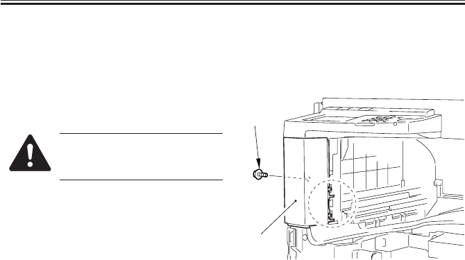
COPYRIGHT
©
2001 CANON INC. 2000 2000 2000 2000 CANON iR2200/iR2800/iR3300 REV.0 MAR. 2001
CHAPTER 7 EXTERNALS AND CONTROLS
7-15 P
5.1.3 Removing the Support Cover
1) Remove the support cover. (1 screw)
2) Remove the left rear cover.
3) Open the front cover.
4) Remove the screw [1], and detach the
support cover [2].
Take care not to break the claw
(circled) behind the support
cover.
F07-501-04
[1]
[2]
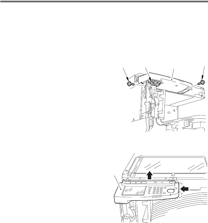
COPYRIGHT
©
2001 CANON INC. 2000 2000 2000 2000 CANON iR2200/iR2800/iR3300 REV.0 MAR. 2001
CHAPTER 7 EXTERNALS AND CONTROLS
7-16 P
5.2 Control Panel
5.2.1 Removing the Control Panel
1) Remove the support cover. (p. 7-15P)
2) Remove the reader front cover. (2
screws) (See the descriptions on the
reader unit.)
3) Remove the two screws [1], and discon-
nect the connector [2].
F07-502-01
4) Shift the control panel [1] to the left,
and lift it to detach.
F07-502-02
[1] [2] [3] [1]
[1] (2) (2)
(1) (1)

COPYRIGHT
©
2001 CANON INC. 2000 2000 2000 2000 CANON iR2200/iR2800/iR3300 REV.0 MAR. 2001
CHAPTER 7 EXTERNALS AND CONTROLS
7-17 P
5.3 PCBs
5.3.1 Removing the DC Controller PCB
1) Remove the rear cover. (7 screws)
2) Remove the five screws [1], and detach
the connector guard plate [2].
3) Disconnect all the connectors of the
harness.
4) Remove the eight screws [3].
5) Disconnect the connector [4] to the
main controller, and detach the DC con-
troller PCB [5].
F07-503-01
5.3.2 Points to Note When Replacing the DC Controller PCB
“Troubleshooting”>Chapter 4 “Troubleshooting Image Faults/Malfunctions” >6.7 “Vari-
able Resistors (VR), Light-Emitting Diodes, and Check Pins by PCB”
5.3.3 Removing the Controller Cover
1) Remove the rear cover. (7 screws)
2) Remove the 12 screws [1] (if the HDD
unit [2] has been removed, 9 screws);
then, detach the controller cover [3].
F07-503-02
[1]
[1]
[1]
[2]
[4] [3]
[3]
[3]
[5]
[3]
[2]
[2]
[2] [2]
[2]
[4]
[4]
[1]
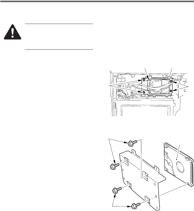
COPYRIGHT
©
2001 CANON INC. 2000 2000 2000 2000 CANON iR2200/iR2800/iR3300 REV.0 MAR. 2001
CHAPTER 7 EXTERNALS AND CONTROLS
7-18 P
5.3.4 Removing the HDD
When removing the HDD, take
full care against static charges.
Also, do not subject the HDD to
impact.
1) Remove the rear cover. (7 screws)
2) Disconnect the connector [1].
3) Remove the four screws [2], and detach
the HDD support base [3].
F07-503-03
4) Remove the four screws [1], and detach
the HDD [2].
F07-503-04
[3]
[2]
[2]
[1]
[2]
[1]
[1]
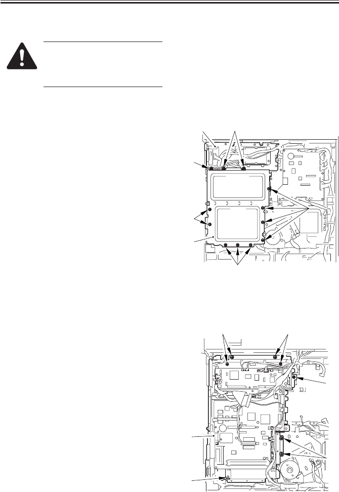
COPYRIGHT
©
2001 CANON INC. 2000 2000 2000 2000 CANON iR2200/iR2800/iR3300 REV.0 MAR. 2001
CHAPTER 7 EXTERNALS AND CONTROLS
7-19 P
5.3.5 Removing the HDD Unit
When removing the HDD unit,
take full care against static elec-
tricity. Do not subject the HDD
unit to impact.
1) Remove the rear cover. (7 screws)
2) Remove the rear right cover. (5 screws)
3) Disconnect the two connectors [1].
4) Remove the eight screws (if the control-
ler cover [3] has been removed, 5
screws); then, detach the HDD unit [2].
F07-503-05
5.3.6 Removing the Controller Box Unit
1) Remove the rear cover. (7 screws)
2) Remove the DC controller PCB. (p. 7-
17P)
3) Remove the HDD unit. (See item 5.3.5)
4) Disconnect all the connectors of the
harness.
5) Remove the eight screws [1], and detach
the controller box unit [2].
F07-503-06
[3]
[1]
[1]
[1]
[1][2]
[3][1]
[1]
[2]
[1]
[1]
[1]
[1]
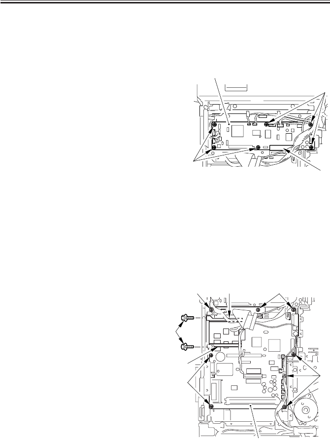
COPYRIGHT
©
2001 CANON INC. 2000 2000 2000 2000 CANON iR2200/iR2800/iR3300 REV.0 MAR. 2001
CHAPTER 7 EXTERNALS AND CONTROLS
7-20 P
5.3.7 Removing the Reader Controller PCB
1) Remove the rear cover. (7 screws)
2) Remove the HDD unit. (p. 7-19P)
3) Disconnect all the connectors of the
harness.
4) Remove the six screws [1].
5) Disconnect the connector [2] to the
main controller, and detach the reader
controller PCB [3].
F07-503-07
5.3.8 When Replacing the Reader Controller PCB
“Troubleshooting”>Chapter 4 “Troubleshooting Image Faults/Malfunctions” >6.7 “Vari-
able Resistors (VR), Light-Emitting Diodes, and Check Pins by PCB”
5.3.9 Removing the Main Controller PCB
1) Remove the rear cover. (7 screws)
2) Remove the right rear cover. (5 screws)
3) Remove the DC controller PCB. (p. 7-
17P)
4) Remove the reader controller PCB. (See
item 5.3.7.)
5) Disconnect all the connectors of the
harness.
6) Remove the screw [1] (1 each), and de-
tach the two PCB guides [2].
7) Remove the eight screws [3], and detach
the main controller PCB [4].
F07-503-08
[3]
[1]
[1]
[2]
[3]
[2] [3]
[3]
[1]
[2]
[4]
[3]
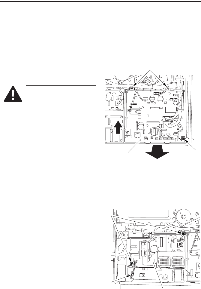
COPYRIGHT
©
2001 CANON INC. 2000 2000 2000 2000 CANON iR2200/iR2800/iR3300 REV.0 MAR. 2001
CHAPTER 7 EXTERNALS AND CONTROLS
7-21 P
5.3.10When Replacing the Main Controller PCB
“Troubleshooting”>Chapter 4 “Troubleshooting Image Faults/Malfunctions” >6.7 “Vari-
able Resistors (VR), Light-Emitting Diodes, and Check Pins by PCB”
5.3.11Removing the Composite Power Supply
1) Remove the rear cover. (7 screws)
2) Disconnect all the connectors.
3) Remove the three screws [1]; then, lift
the composite power supply [2] about 5
mm, and detach it to the front.
If you have replaced the com-
posite power supply, be sure to
enter the settings indicated on
the service label in service
mode:
COPIER>ADJUST>DEVELOP>
DE-DC.
F07-503-09
5.3.12Removing the Accessories Power Supply
1) Remove the rear cover. (7 screws)
2) Disconnect all the connectors of the
harness.
3) Disconnect the connector [1] to the
main power supply.
4) Remove the two screws [2], and detach
the accessories power supply [3].
F07-503-10
[1]
[1]
[2]
(2)
(2)(1)
[2]
[1]
[3]
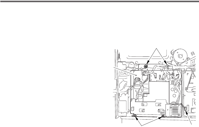
COPYRIGHT
©
2001 CANON INC. 2000 2000 2000 2000 CANON iR2200/iR2800/iR3300 REV.0 MAR. 2001
CHAPTER 7 EXTERNALS AND CONTROLS
7-22 P
5.3.13Removing the Main Power Supply
1) Remove the accessories power supply.
(See item 5.3.12.)
2) Disconnect all the connectors.
3) Disconnect the connector [1] to the
composite power supply.
4) Remove the four screws [2], and detach
the main power supply [3].
F07-503-11
[1]
[2]
[3]
[2]

COPYRIGHT
©
2001 CANON INC. 2000 2000 2000 2000 CANON iR2200/iR2800/iR3300 REV.0 MAR. 2001
CHAPTER 8
PAPER DECK-L1

COPYRIGHT
©
2001 CANON INC. 2000 2000 2000 2000 CANON iR2200/iR2800/iR3300 REV.0 MAR. 2001
CHAPTER 8 PAPER DECK-L1
8-1 P
1.1 Pickup
1.1.1 Outline
The paper deck (hereafter, “deck”) is capable of accommodating as many as 2500 sheets
(A4/LTR, B5; 80 g/m2 paper) at a time, and is designed to operate in response to control
signals from the DC controller of its host machine.
The lifter of the deck is driven by the deck lifter motor (M2D), and paper is picked up and
moved by the drive of the deck main motor (M1D).
1.1.2 Pickup Operation
The paper placed inside the deck is held up by the lifter, and is kept in a specific pickup
position.
When the Start key is pressed and the deck pickup clutch (CL2D) goes ON, the drive of
the deck main motor (M1D) rotates the pickup roller to pick up paper; at this time, the
pickup/feeding roller and the separation roller serve to make sure that only one sheet of pa-
per is moved forward. When the deck pickup sensor (PS1D) detects paper thereafter, the
deck pickup roller releasing solenoid (SL1D) goes ON so that the pickup roller leaves the
stack of paper.
The deck feeding roller starts to rotate when the deck feeding clutch (CL1D) goes ON.
The picked paper is moved to the registration roller of the host machine, and is made to arch
for removal of the slack.
The registration roller is controlled so that the leading edge of paper will match the image
on the photosensitive drum.

COPYRIGHT
©
2001 CANON INC. 2000 2000 2000 2000 CANON iR2200/iR2800/iR3300 REV.0 MAR. 2001
CHAPTER 8 PAPER DECK-L1
8-2 P
F08-101-01
PS1D
PS6D CL2D
M1D
SL1D
DC controller PCB (host machine)
Deck driver PCB
Deck feed detection signal
(P_OUT_SENS)
Deck pickup clutch drive signal
(FEED_CL_ON*)
Deck pickup roller releasing solenoid drive signal
(PICKUP_SL_ON*)
Deck main motor rive signal
Deck pickup detection signal
(FEED_SENS)
CL1D
Deck feeding clutch drive signal
(PULL_CL_ON*)
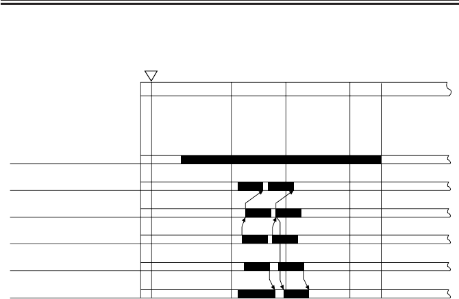
COPYRIGHT
©
2001 CANON INC. 2000 2000 2000 2000 CANON iR2200/iR2800/iR3300 REV.0 MAR. 2001
CHAPTER 8 PAPER DECK-L1
8-3 P
1.1.3 Sequence of Pickup Operations (deck)
F08-101-02
INTR LSTR STBY
Start key ON
Deck main motor
(M1D)
Deck pickup clutch
(CL2D)
Deck pickup roller
releasing solenoid (SL1D)
Deck pickup sensor
(PS6D)
Deck feed sensor
(PS1D)
Deck feeding clutch
(CL1D)
SCAN PRINT
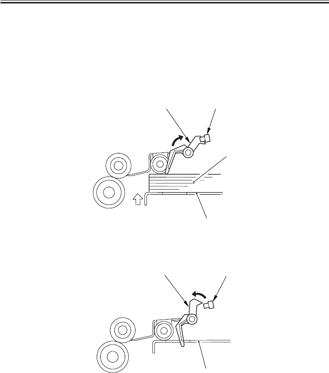
COPYRIGHT
©
2001 CANON INC. 2000 2000 2000 2000 CANON iR2200/iR2800/iR3300 REV.0 MAR. 2001
CHAPTER 8 PAPER DECK-L1
8-4 P
1.2 Detecting Paper in the Deck
1.2.1 Detecting the Presence/Absence of Paper
The presence/absence of paper inside the deck is detected by the deck paper absence sen-
sor [1] (PS2D). When the paper [3] placed on the lifter [2] runs out and, as a result, the pa-
per detecting lever [4] of the pickup roller assembly leaves the deck paper absent sensor, the
control panel of the host machine will indicate the absence of paper.
F08-102-01
F08-102-02
1.2.2 Switching the Deck Paper Size
If you have to change the paper size of the deck at time of installation or to comply with a
request of the user, adjust the guide plate inside the deck to suit the new paper size and enter
the new paper size in service mode (OPTION>ACC-DK-P).
[2]
[1]
[3]
[4]
[2]
[1]
[4]

COPYRIGHT
©
2001 CANON INC. 2000 2000 2000 2000 CANON iR2200/iR2800/iR3300 REV.0 MAR. 2001
CHAPTER 8 PAPER DECK-L1
8-5 P
1.2.3 Detecting the Level of Paper in the Deck
The deck uses the deck paper supply position sensor (PS8D), deck paper level sensor
(PS7D), and deck paper absent sensor (PS2D) to find out how much paper remains inside its
compartment and to indicate an approximate level in the control panel of the host machine
as shown in the following table (indicating combinations of paper levels and sensor states):
Paper level PS2D PS8D PS7D Indication in
control panel
100% to about 50% 1 1 1
about 50% to about 10% 1 1 0
10% 1 0 0
No paper 0 0 0
1: light-blocking plate over the sensor.
0: light-blocking plate not over the sensor.
T08-102-01

COPYRIGHT
©
2001 CANON INC. 2000 2000 2000 2000 CANON iR2200/iR2800/iR3300 REV.0 MAR. 2001
CHAPTER 8 PAPER DECK-L1
8-6 P
1.3 Deck Lifter
1.3.1 Detecting the Presence/Absence of Paper
The lifter of the deck is connected to a reel by means of a cable, and is driven by the deck
lifter motor (M2D), whose direction of rotation changes the direction (up/down) of the
movement of the lifter.
When the compartment is slid inside the deck, the deck open detecting switch (SW1D) is
pushed; the deck then starts to move up when the deck open sensor (PS9D) detects the light-
blocking plate. It will stop to move up when the deck lifter position sensor (PS4D) detects
the top face of the stack of paper placed on it.
If, for some reason, the lifter fails to stop moving up after the sensor lever blocks the deck
lifter position sensor, the deck lifter upper limit sensor (PS3D) will go ON to stop it and
thereby to prevent image.
When the deck open switch (SW100D) is pushed, on the other hand, the lifter starts to
move down, and continues to move down until it leaves the sensor lever of the deck paper
supply position sensor (PS8D; falling edge of the sensor output).
When supplied, the paper pushes the lever of the deck paper supply position sensors, and
the lifter will move farther down until the stack of paper leaves the sensor lever.
Each time paper is supplied, the lifter repeats its descent movement until the deck lifter
lower limit detecting switch (SW2D) is pushed (point of maximum paper supply).
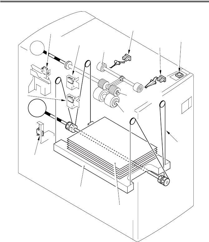
COPYRIGHT
©
2001 CANON INC. 2000 2000 2000 2000 CANON iR2200/iR2800/iR3300 REV.0 MAR. 2001
CHAPTER 8 PAPER DECK-L1
8-7 P
M2D
M1D [1]
[2]
[3]
[4]
[5]
[6]
[7]
[8]
[9]
[10]
[11]
[12]
[13]
[14]
[15]
[9] Deck lifter motor
[10]Pickup roller
[11]Feeding roller
[12]Separation roller
[13]Deck lifter cable
[14]Lifter
[15]Copy paper
[1] Deck lifter upper limit sensor
[2] Deck lifter position sensor
[3] Deck paper supply position sensor
[4] Deck paper level sensor
[5] Deck open detecting switch
[6] Deck lifter lower limit detecting switch
[7] Deck open switch
[8] Deck main motor
F08-103-01
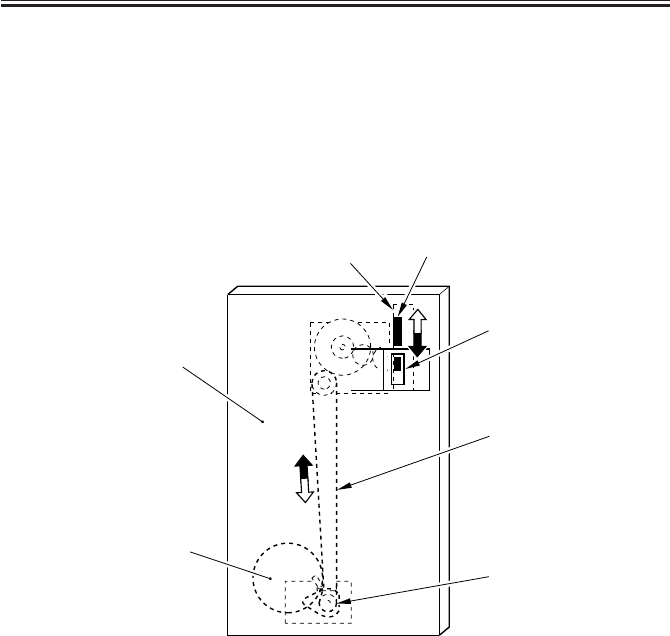
COPYRIGHT
©
2001 CANON INC. 2000 2000 2000 2000 CANON iR2200/iR2800/iR3300 REV.0 MAR. 2001
CHAPTER 8 PAPER DECK-L1
8-8 P
1.3.2 Indicating the Level of Paper (deck front cover)
The drive of the deck lifter motor [1] (M2D) is received by a coupling [2], and is for-
warded to the rack [4] by way of the drive belt [3]. The rack is equipped with a black belt
[4] designed to move inside the window [7] in the deck front cover [6] in keeping with the
movement of the rack.
When the paper starts to run out and the lifter moves up to the pickup position as a result,
the area of the black belt in the window accordingly increases (while the white area de-
creases), indicating the increasing level of paper.
F08-103-02
M2D
[1]
[2]
[3]
[4] [5]
[6]
[7]
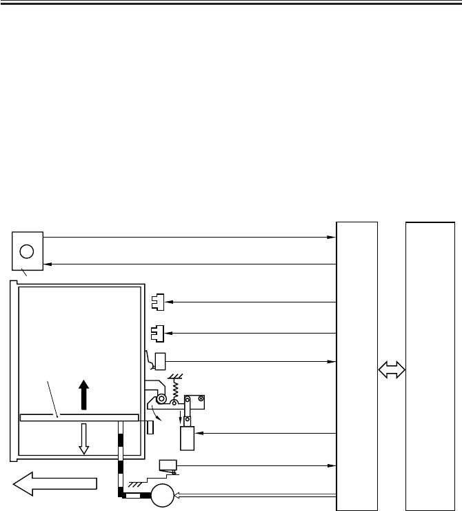
COPYRIGHT
©
2001 CANON INC. 2000 2000 2000 2000 CANON iR2200/iR2800/iR3300 REV.0 MAR. 2001
CHAPTER 8 PAPER DECK-L1
8-9 P
1.4 Opening/Closing of the Compartment
1.4.1 Opening/Closing of the Compartment
When the deck open switch (SW100D) is pushed, the deck open solenoid (SL2D) goes
ON, and the compartment is released; as a result, the compartment is pushed several centi-
meters forward. At the same time, the deck lifter motor (M2D) starts to rotate, and the lifter
inside the compartment moves down.
When the compartment is pushed inside the deck by hand, the deck open sensor (PS9D)
will detect the light-blocking plate of the compartment, and the lifter will move up to the
pickup position.
When the deck lifter motor starts to rotate, the deck open indicator (LED100D) on the
open switch PCB will go ON or start to flash.
F08-104-01
Deck lifter lower limit detection signal
(DLLD)
J4
- 7
Deck lifter motor drive signal
J4
-9,10
M2D
DC
controller
PCB
Deck
drive
PCB
Deck lifter
Deck open detection signal
(DOPD
*
)
Deck open solenoid drive signal
Deck open signal
(DECK_OPEN_SW)
Open
Deck open indicator LED ON signal
(LEDSW_LEDON)
SW2D
SL2D
SW1D
Open switch PCB
SW100D
LED100D
J20
-1
J20
-4
Deck lifter upper limit detection signal
(LIFT_M_UPLMT)
PS3D
J5A
- 9
Deck open detection signal
(DECK_OPEN_SENS)
PS9D
(compartment)
J5A
- 4
J5A
- 1
J6
- 7
J7
- 3
J6
-2
(host machine)
(DECK_LOCKOFF_SL_ON*)
9 : LIFT_M_UP
10 : LIFT_M_DOWN
( )
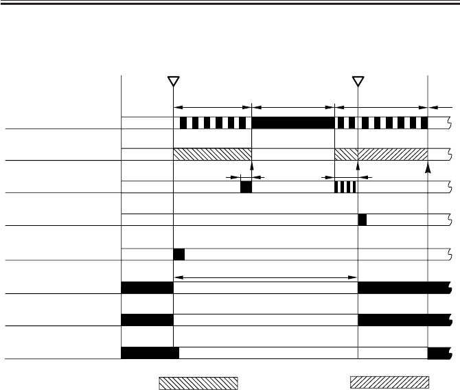
COPYRIGHT
©
2001 CANON INC. 2000 2000 2000 2000 CANON iR2200/iR2800/iR3300 REV.0 MAR. 2001
CHAPTER 8 PAPER DECK-L1
8-10 P
1.4.2 Sequence of Operations (opening/closing of the compartment)
F08-104-02
ON FlashingFlashing
Compartment open
OFF
Deck open switch ON
Deck open indicator
(LED100D)
Deck lifter motor
(M2D)
Deck paper supply
position sensor (PS8D)
Deck open detecting
switch (SW1D)
Deck open solenoid
(SL2D)
Deck lifter position
sensor (PS4D)
Deck lifter DOWN Deck lifter UP
Compartment set
**
* : varies depending on the amount of paper.
Deck lifter lower
limit detection (SW2D)
Deck open sensor
(PS9D)
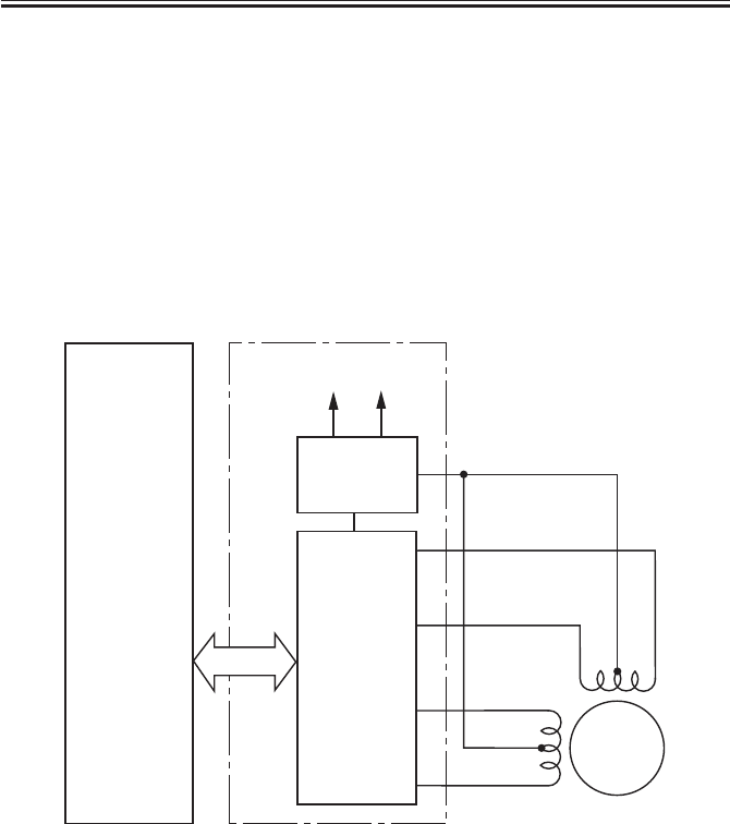
COPYRIGHT
©
2001 CANON INC. 2000 2000 2000 2000 CANON iR2200/iR2800/iR3300 REV.0 MAR. 2001
CHAPTER 8 PAPER DECK-L1
8-11 P
1.5 Controlling the Deck Motor
1.5.1 Controlling the Deck Main Motor (M1D)
The deck main motor (M1D) is a stepping motor, and is controlled by the DC controller
of the host machine. The following figure shows the circuit used to drive the deck main mo-
tor, and the circuit has the following function:
[1] Turning on/off the deck main motor
a. Turning On/Off the Motor
The outputs FEED_M_A, FEED_M_A*, FEED_M_B, and FEED_M_B* are controlled
using serial signals from the host machine to turn on/off the deck main motor and switch its
speed of rotation.
F08-105-01
M1D
+24V +5V
FEED_M_A
FEED_M_A*
FEED_M_B*
FEED_M_B
Deck main
motor
Side deck driver PCB
DC controller
PCB
Motor rotation
control circuit
Motor drive
current switch

COPYRIGHT
©
2001 CANON INC. 2000 2000 2000 2000 CANON iR2200/iR2800/iR3300 REV.0 MAR. 2001
CHAPTER 8 PAPER DECK-L1
8-12 P
1.5.2 Controlling the Deck Lifter Motor (M2D)
The deck lifter motor control circuit is found on the side deck driver PCB. F08-105-02 is
a block diagram of the PCB.
The combination circuit found in the figure consists of various logic circuits, and a spe-
cific combination is used to rotate the deck lifter motor clockwise or counterclockwise: out-
put signals from sensors and deck lifter motor drive command and deck lifter ascent com-
mand from the DC controller of the host machine.
If the deck lifter position sensor (PS4D) does not detect the lifter within a specific period
of time in spite of the presence of the deck lifter UP signal, an alarm (code: 05) will be indi-
cated in service mode: DISPLAY>ALARM1>BODY.
[1] Conditions for Moving Up the Lifter
• The deck is connected to its host machine. → The deck set signal
(DECK_MOUNT_SENS) is ‘1’.
• The compartment is closed. → The deck open detection signal (DECK_OPEN_SENS)
is ‘1’.
• The compartment is closed. → The deck open detecting switch (DECK_OPEN_SW) is
ON.
• The deck upper limit detection signal (LIFT_M_DOWN) is ‘0’.
• The deck lifter UP signal (LIFT_M_UP) is ‘0’.
The above conditions will move up the lifter.
[2] Conditions for Moving Down the Lifter
• The compartment is open. The deck open detection signal (DECK_OPEN_SNS) is ‘0’.
• The deck lifter lower limit detection signal (LIFT_LOW_LIMIT) is ‘0’ and, in addition,
the deck lifter position detection signal (PAP_TOP_SENS) is ‘0’.
• The deck lifter motor DOWN signal (LIFT_M_DOWN) is ‘0’.
• The deck lifter UP signal (LIFT_M_UP) is ‘1’.
The above conditions move down the lifter.
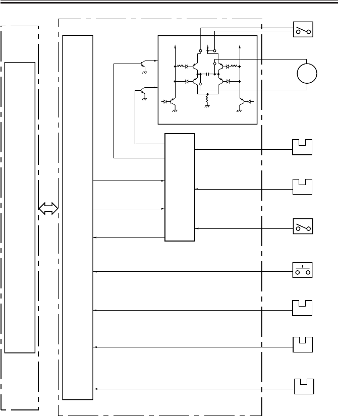
COPYRIGHT
©
2001 CANON INC. 2000 2000 2000 2000 CANON iR2200/iR2800/iR3300 REV.0 MAR. 2001
CHAPTER 8 PAPER DECK-L1
8-13 P
M2D
Host
machine
DC
controller
PCB
Combina-
tion
circuit
Motor drive circuit
24V 24V 24V
Deck lifter motor
Side deck driver PCB
Deck open detecting
switch (SW1D)
Deck lifter position
sensor
PS4D
Deck lifter position
detection signal
(PAP_TOP_SENS)
PS8D
Deck paper supply
position sensor
Deck paper supply position signal
(PAP_VL_EMP_U)
Deck lifter lower limit
detecting switch (SW2D)
Deck lifter lower
limit signal
(LIFT_LOW_LMT)
PS9D
Deck open sensor
Deck open detection signal
(DECK_OPEN_SENS)
PS3D
Deck lifter upper
limit sensor
Deck lifter upper
limit signal
(LIFT_M_UPLMT)
Deck open switch
(SW100D)
Deck open signal
(DECK_OPEN_SW)
Deck lifter motor drive
signal (LIFT_UP_LIM)
Deck motor error drive
signal (LIFT_M_ERR)
Deck lifter UP signal
(DECK_UP)
Deck lifter motor UP drive signal
Deck lifter motor
DOWN drive signal
Communi-
cation
conversion
(IC4)
Note: The communication conversion IC (IC4) is used to convert between serial signals
and parallel signals.
Deck set sensor
PS5D
Deck set signal
(DECK_MOUNT_SENS)
F08-105-02
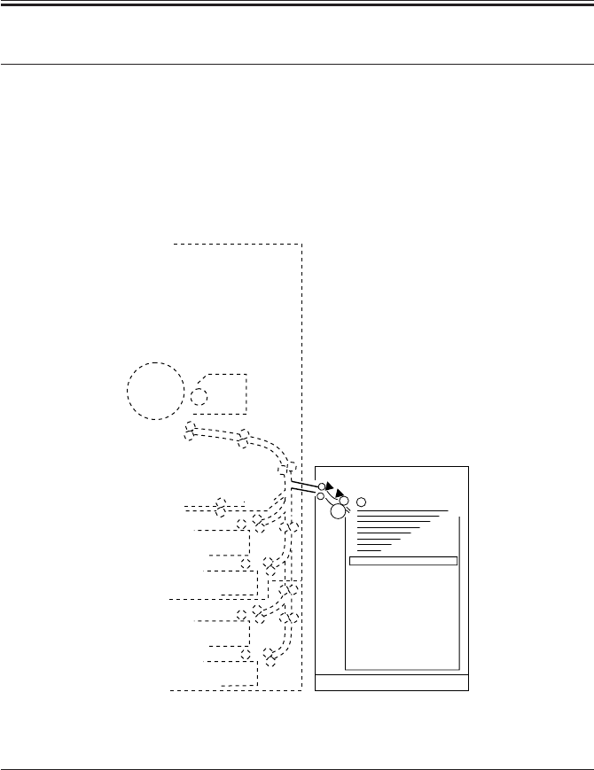
COPYRIGHT
©
2001 CANON INC. 2000 2000 2000 2000 CANON iR2200/iR2800/iR3300 REV.0 MAR. 2001
CHAPTER 8 PAPER DECK-L1
8-14 P
2 Detecting Jams
2.1 Outline
The paper deck is equipped with two sensors (F08-201-01) to monitor the movement of
paper. A jam is identified in relation to the signals from the sensors at such times as pro-
grammed in the DC controller of the host machine. When the DC controller of the host ma-
chine identifies a jam, the machine will deliver the sheets that are ahead of the jam, and will
stop the operation; thereafter, the host machine will indicate instructions for jam removal in
its control panel.
F08-201-01
Notation Name Function
PS1D Deck feed sensor Detection of delay jam
PS6D Deck pickup sensor Detection of delay jam
T08-201-01
PS1D
PS6D
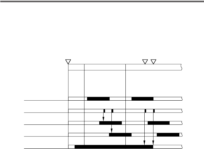
COPYRIGHT
©
2001 CANON INC. 2000 2000 2000 2000 CANON iR2200/iR2800/iR3300 REV.0 MAR. 2001
CHAPTER 8 PAPER DECK-L1
8-15 P
The DC controller of the host machine will identify a jam in response to the following
condition:
1. Paper exits over the deck feed sensor (PS6D) while the machine is in wait-up state or
standby state when the power switch of the host machine is turned on.
2. Deck Pickup/Vertical Path Delay Jam
F08-201-02
Start key ON Jam indicator ON
INTR SCAN PRINT
Deck pickup clutch
(CL2D)
Jam check
Deck pickup sensor
(PS6D)
Deck feed sensor
(PS1D)
Deck main motor
(M1D)
Normal Error

COPYRIGHT
©
2001 CANON INC. 2000 2000 2000 2000 CANON iR2200/iR2800/iR3300 REV.0 MAR. 2001
CHAPTER 8 PAPER DECK-L1
8-16 P
3 Disassembly and Assembly
The discussions that follow cover the machine’s mechanical characteristics and how to
disassemble/assemble the machine. Keep the following in mind whenever you work with the
machine:
1. The power plug must remain disconnected for safety when disassembling/assembling
the machine.
2. Unless otherwise noted, the machine may be assembled by reversing the steps used to
disassemble it.
3. The screws must be identified by type (length, diameter) and location.
4. The mounting screws used for the grounding wire and the varistors come with a washer,
which must not be left out when assembling the machine.
5. As a rule, the machine must not be operated with any of its parts removed.
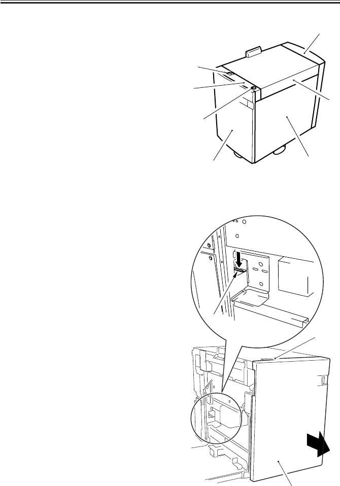
COPYRIGHT
©
2001 CANON INC. 2000 2000 2000 2000 CANON iR2200/iR2800/iR3300 REV.0 MAR. 2001
CHAPTER 8 PAPER DECK-L1
8-17 P
3.1 External Covers
[1] Deck releasing grip
[2] Front upper cover
[3] Compartment open/closed switch
[4] Front cover
[5] Right cover
[6] Upper cover
[7] Rear cover
F08-301-01
3.1.1 Sliding Out the Compartment
1) Push the deck releasing grip [1] to re-
lease the deck from its host machine;
then, push down the latch plate [2] at
the left rear to open the compartment
[3].
F08-301-02
[1]
[2]
[3]
[4] [5]
[6]
[7]
[1]
[3]
[2]
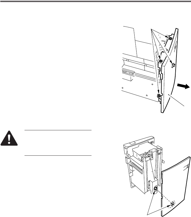
COPYRIGHT
©
2001 CANON INC. 2000 2000 2000 2000 CANON iR2200/iR2800/iR3300 REV.0 MAR. 2001
CHAPTER 8 PAPER DECK-L1
8-18 P
3.1.2 Removing the Front Cover
1) Sliding out the compartment. (p. 8-17P)
2) Loosen the four screws [1], and shift the
front cover [2] to detach it to the front.
F08-301-03
When mounting the front cover,
be sure to match it against the
coupling [1] of the paper level
indicator.
F08-301-04
[1]
[2]
[1]

COPYRIGHT
©
2001 CANON INC. 2000 2000 2000 2000 CANON iR2200/iR2800/iR3300 REV.0 MAR. 2001
CHAPTER 8 PAPER DECK-L1
8-19 P
Be sure to mount the front cover
so that gap A between the front
cover [1] and the front upper
cover [2] is 3 ±1 mm.
F08-301-05
If you operate the deck without
matching the position of the pa-
per level indicator and the deck
lifter, the drive mechanism of
the paper level indicator can be-
come damaged. If you have
moved the paper level indicator
drive belt behind the front cover
or the deck lifter, be sure to per-
form the following two tasks:
Adjusting the Paper Level Indicator
1) Move the drive belt [2] of the paper
level indicator behind the front cover
[1] by hand so that the white area inside
the window [3] increases, i.e., in the di-
rection for the arrow [4]; move it until a
little resistance is felt.
F08-301-06-A
[1]
[2]
A
[1]
[2]
[3]
[4]
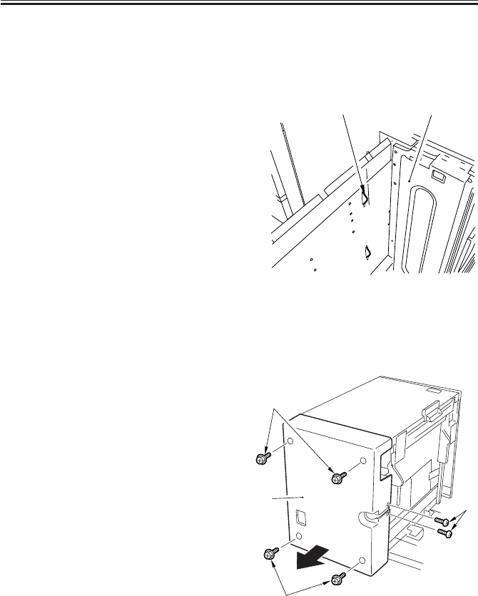
COPYRIGHT
©
2001 CANON INC. 2000 2000 2000 2000 CANON iR2200/iR2800/iR3300 REV.0 MAR. 2001
CHAPTER 8 PAPER DECK-L1
8-20 P
Moving the Deck Lifter
1) Sliding out the compartment. (p. 8-17P)
2) If paper is found, remove all of it.
3) Connect the power plug, and turn on the
power switch of the host machine.
4) Push the flag [2] of the paper supply
position sensor found inside the com-
partment so that the deck lifter will
move down. (The deck lifter will stop
where you release the sensor flag.)
F08-301-06-B
5) Disconnect the power plug.
3.1.3 Removing the Rear Cover
1) Release the deck from its host machine;
then, remove the six crews [1], and de-
tach the rear cover [2].
F08-301-07
[2] [1]
[1]
[2] [1]
[1]
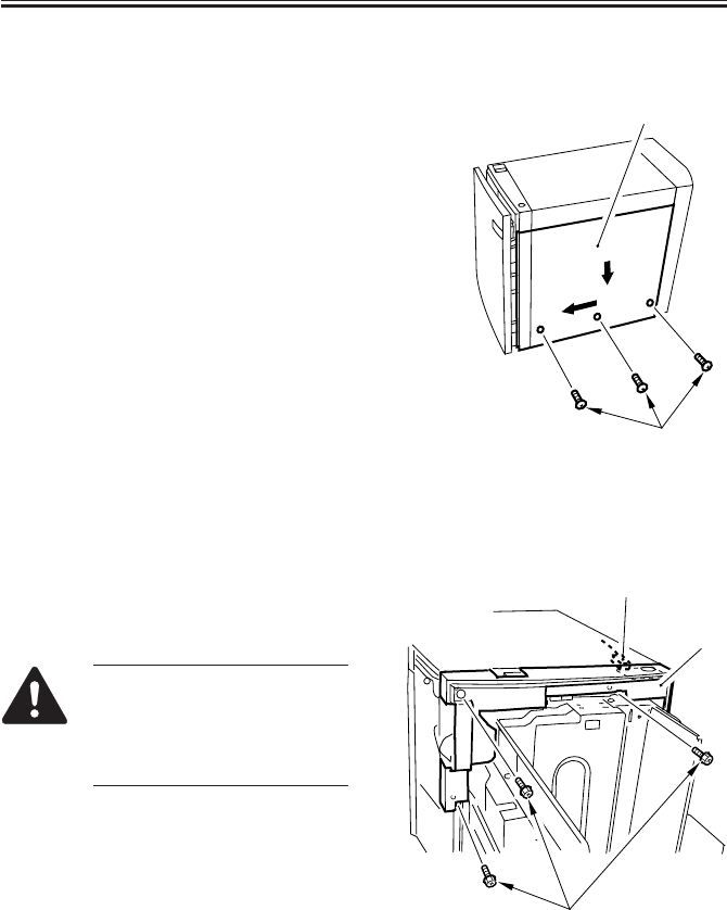
COPYRIGHT
©
2001 CANON INC. 2000 2000 2000 2000 CANON iR2200/iR2800/iR3300 REV.0 MAR. 2001
CHAPTER 8 PAPER DECK-L1
8-21 P
3.1.4 Removing the Right Cover
1) Sliding out the compartment. (p. 8-17P)
2) Remove the three screws [1], and shift
the right cover [2] down, and then de-
tach it to the front.
F08-301-08
3.1.5 Removing the Front Upper Cover
1) Sliding out the compartment. (p. 8-17P)
2) Remove the three screws [1], and dis-
connect the connector [2]; then, detach
the front upper cover [3].
When mounting the front upper
cover, take care not to trap the
harness on the open switch PCB
or to forget connecting the con-
nectors.
F08-301-10
[2]
[1]
[2]
[1]
[3]
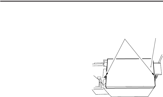
COPYRIGHT
©
2001 CANON INC. 2000 2000 2000 2000 CANON iR2200/iR2800/iR3300 REV.0 MAR. 2001
CHAPTER 8 PAPER DECK-L1
8-22 P
3.1.6 Removing the Upper Cover
1) Remove the rear cover. (p. 8-20P)
2) Sliding out the compartment. (p. 8-17P)
3) Remove the front upper cover. (p. 8-
21P)
4) Remove the two screws [1], and detach
the upper cover [2].
F08-301-11
[2]
[1]
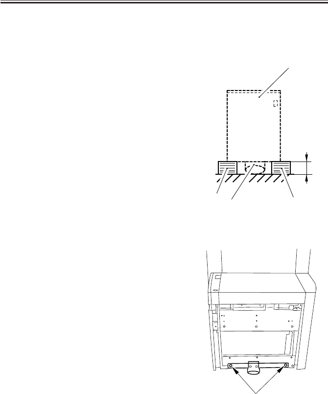
COPYRIGHT
©
2001 CANON INC. 2000 2000 2000 2000 CANON iR2200/iR2800/iR3300 REV.0 MAR. 2001
CHAPTER 8 PAPER DECK-L1
8-23 P
3.2 Paper Deck Body
3.2.1 Removing the Deck from the Host Machine
1) To prevent deformation of the roller
support plate [1], lay copy paper [3] (A:
about 8 cm) or the like on the floor on
which to place the deck [2].
F08-302-01
2) Remove the right cover. (p. 8-21P)
3) Remove the two screws [1] from the
right side.
F08-302-02-A
[2]
[3]
[3] [1]
A
[1]
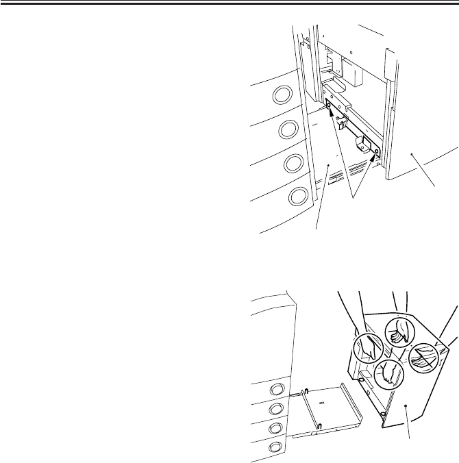
COPYRIGHT
©
2001 CANON INC. 2000 2000 2000 2000 CANON iR2200/iR2800/iR3300 REV.0 MAR. 2001
CHAPTER 8 PAPER DECK-L1
8-24 P
4) Remove the two screws [1] on the left,
and detach the deck [2] from the deck
base [3].
F08-302-02-B
5) Holding the deck [1] by the areas indi-
cated, move and place the deck on the
block of paper prepared previously (p.
8-23P).
F08-302-03
[1] [2]
[3]
[1]
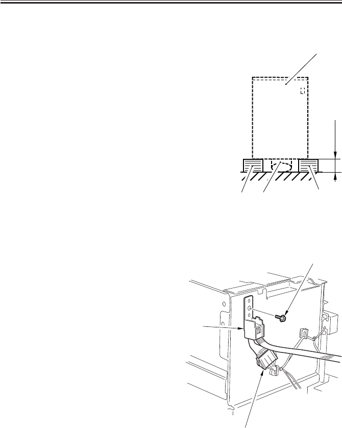
COPYRIGHT
©
2001 CANON INC. 2000 2000 2000 2000 CANON iR2200/iR2800/iR3300 REV.0 MAR. 2001
CHAPTER 8 PAPER DECK-L1
8-25 P
3.2.2 Removing the Compartment
1) To prevent deformation of the roller
support plate [1], lay copy paper [3] (A:
about 8 cm) or the like on the floor on
which to place the deck [2].
F08-302-04
2) Sliding out the compartment. (p. 8-17P)
3) Remove the right cover. (p. 8-21P)
4) Disconnect the connector [1] at the rear
of the compartment, and remove the
screw [2]; then, detach the harness unit
[3].
F08-302-05
about 8 cm
[2]
[3]
[1]
[3]
[1]
[3]
[2]
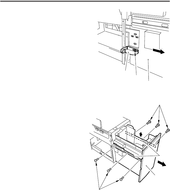
COPYRIGHT
©
2001 CANON INC. 2000 2000 2000 2000 CANON iR2200/iR2800/iR3300 REV.0 MAR. 2001
CHAPTER 8 PAPER DECK-L1
8-26 P
5) Remove the screw [1] at the left of the
deck, and remove the stopper plate [2];
then, slide out the compartment [2] to
the front.
F08-302-06
6) Remove the three screws [2] each from
the left and the right of the compart-
ment rail [1]; then, lift the compartment
[3] about 1 cm, and remove it to the
front.
7) Place the compartment [3] on the block
of copy paper prepared previously. (p.
8-25P)
F08-302-07
[3]
[2] [1]
[2]
[1]
[2]
[3]
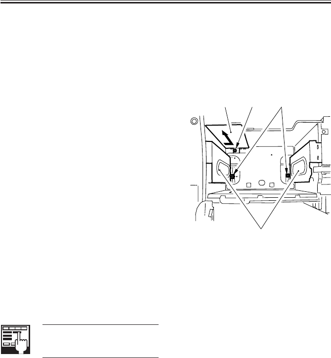
COPYRIGHT
©
2001 CANON INC. 2000 2000 2000 2000 CANON iR2200/iR2800/iR3300 REV.0 MAR. 2001
CHAPTER 8 PAPER DECK-L1
8-27 P
3.2.3 Changing the Deck Paper Size
If the deck paper size must be changed to
suit the needs of the user, perform the fol-
lowing:
1) Remove the front cover. (p. 8-18P)
2) If the lifter is up, move it to its lower
limit. (p. 8-20P)
3) Remove the screw [1], and mount the
paper trailing edge guide plate [2] to
suit the new paper size. (Do not mount
it, however, if the new size is LTR.)
4) Remove the screw [3] (1 each), and
mount the left and right guide plates [4]
to suit the new paper size.
F08-302-08
3.2.4 After Changing the Deck Paper Size
Execute 'machine settings selection' in
service mode, and make settings to suit the
selected paper size.
COPIER>OPTION>ACC>DK-
P
Machine Settings
[2] [1] [3]
[4]
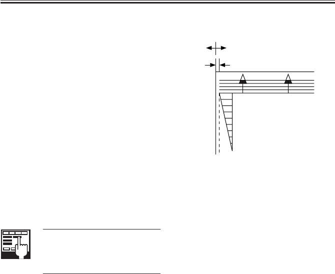
COPYRIGHT
©
2001 CANON INC. 2000 2000 2000 2000 CANON iR2200/iR2800/iR3300 REV.0 MAR. 2001
CHAPTER 8 PAPER DECK-L1
8-28 P
3.2.5 Checking the Image Rear Front Position
Make copies from the Paper Deck in Di-
rect, and check to make sure that the margin
along the image front is 2.5 ± 1.5 mm. Oth-
erwise, adjust the registration. (See item
3.2.6.)
F08-302-09
3.2.6 Adjusting the Cassette Rear Front Registration
Execute 'image read start position adjust-
ment' in service mode.
COPIER>FUNCTION>DK-
ADJ-Y
Use it to adjust the image read
start position.
If correction in service mode fails, make
the following adjustments.
0
2
4
6
8
10
(-) (+)
2.5±1.5mm
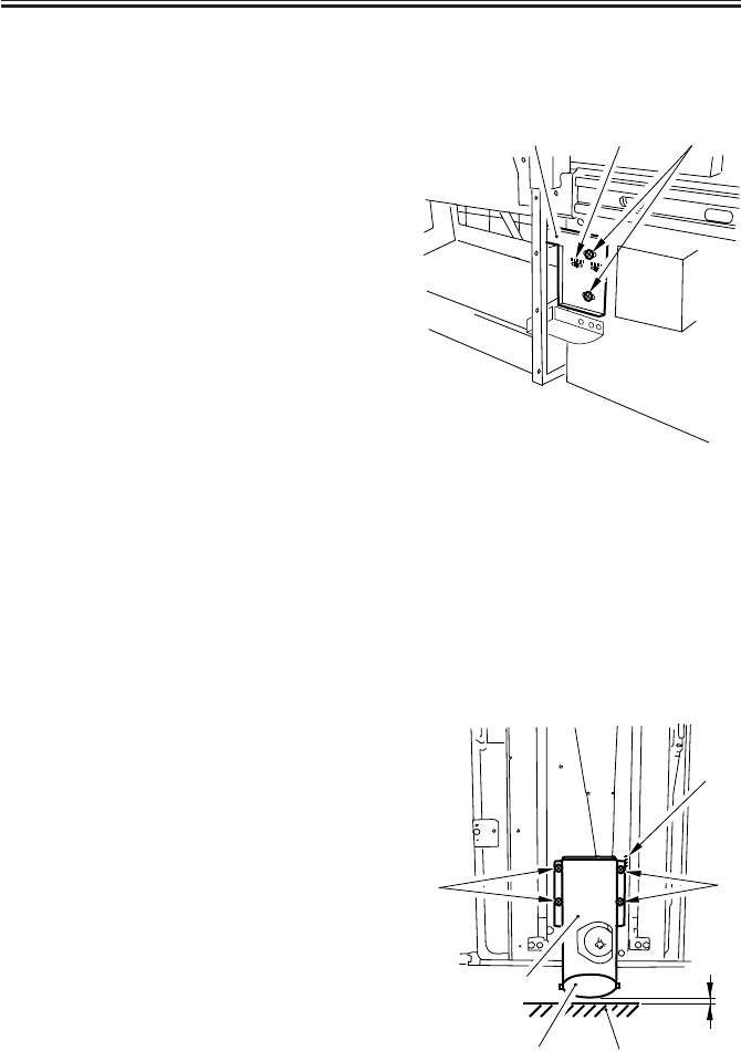
COPYRIGHT
©
2001 CANON INC. 2000 2000 2000 2000 CANON iR2200/iR2800/iR3300 REV.0 MAR. 2001
CHAPTER 8 PAPER DECK-L1
8-29 P
3.2.7 Adjusting the Registration for the Deck
If you must adjust the left/right registra-
tion (standard: 0 ±1.5 mm), perform the fol-
lowing:
1) Sliding out the compartment. (p. 8-17P)
2) Using the two screws [2], change the
position of the latch plate [1] of the
deck open solenoid (SL2D) found at the
left rear. (At this time, use the index [3]
on the latch plate as a reference.)
F08-302-10
3) Close the compartment, and check to
make sure that the gap of the front cover
is 3 ±1 mm.
4) If the gap is not 3 ±1 mm, adjust the
front cover. (p. 8-19P)
3.2.8 Adjusting the Position of the Support Member
If the compartment cannot be opened/
closed smoothly and the position of the sup-
port roller must be adjusted, perform the
following:
1) Remove the front cover. (p. 8-18P)
2) Using the four screws [4] of the roller
support plate [3], make adjustments so
that the support roller [1] and the floor
[2] is about 3 mm when the compart-
ment is fully slid out. (At this time, use
the scale [5] on the front side plate as a
reference.)
F08-302-11
[1] [3] [2]
[4]
[5]
[2]
[1]
[3] A
[4]
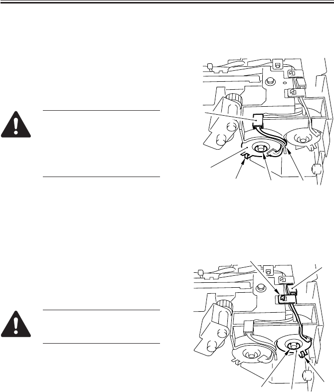
COPYRIGHT
©
2001 CANON INC. 2000 2000 2000 2000 CANON iR2200/iR2800/iR3300 REV.0 MAR. 2001
CHAPTER 8 PAPER DECK-L1
8-30 P
3.3 Drive System
3.3.1 Removing the Deck Pickup Clutch (CL2D)
1) Remove the deck pickup unit. (p. 8-
37P)
2) Disconnect the connector [1], and re-
move the E-ring [2]; then, detach the
deck pickup clutch [3].
When mounting the deck
pickup clutch, be sure to fit the
clutch with the rotation stop [4].
In addition, be sure to hook the
harness along the U-groove [5]
of the guide.
F08-303-01-A
3.3.2 Removing the Deck Feeding Clutch (CL1D)
1) Remove the deck pickup unit. (p. 8-
37P)
2) Remove the harness retainer [1], discon-
nect the connector [2], and remove the
E-ring [3]; then, detach the deck feed-
ing clutch [4].
When mounting the deck feed-
ing clutch, be sure to fit the
clutch in the rotation stop [5].
F08-303-01-B
[1]
[3]
[2]
[4] [5]
[1]
[3]
[2]
[4] [5]
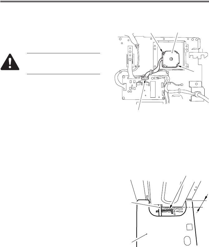
COPYRIGHT
©
2001 CANON INC. 2000 2000 2000 2000 CANON iR2200/iR2800/iR3300 REV.0 MAR. 2001
CHAPTER 8 PAPER DECK-L1
8-31 P
3.3.3 Removing the Deck Main Motor (M1D)
1) Remove the rear cover. (p. 8-20P)
2) Disconnect the connector [1], and re-
move the two screws [2] : then, detach
the deck main motor [3].
At this time, take care not to
damage the gear at the tip of the
motor spindle.
F08-303-02
3.3.4 Removing the Deck Lifter Motor (M2D)
1) Sliding out the compartment. (p. 8-17P)
2) If the lifter is up, move it so that it is
about 7 cm from the base plate of the
compartment. (p. 8-20P)
3) Fit a hex wrench [2] into the opening in
the lifter drive shaft [1] to fix the lifter
drive shaft [3] in place (against rota-
tion).
F08-303-03
[1]
[3]
[2]
[2]
[2]
[3]
[4]
A
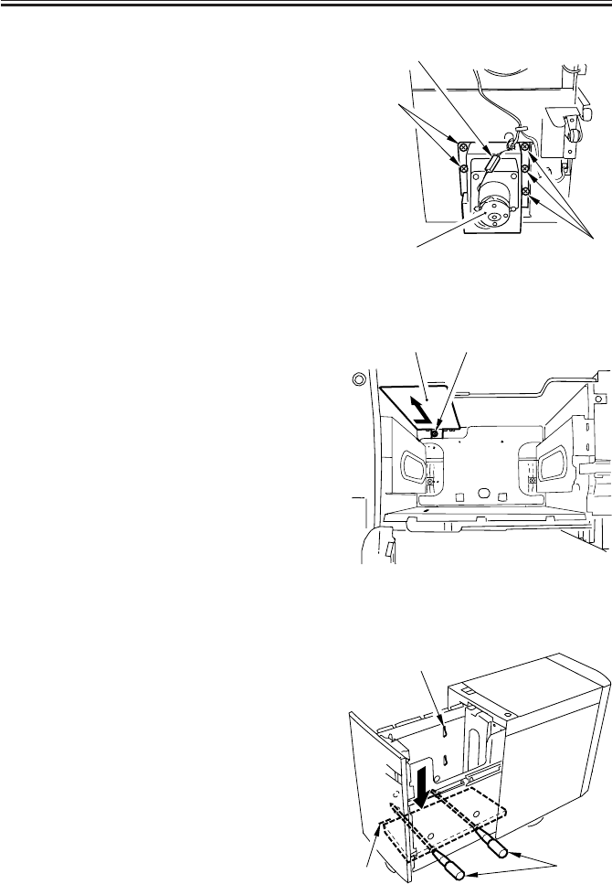
COPYRIGHT
©
2001 CANON INC. 2000 2000 2000 2000 CANON iR2200/iR2800/iR3300 REV.0 MAR. 2001
CHAPTER 8 PAPER DECK-L1
8-32 P
4) Remove the compartment. (p. 8-25P)
5) Disconnect the connector [1], and re-
move the five screws [2]; then, detach
the deck lifter motor unit [3].
F08-303-04
3.3.5 Removing the Lifter Cable (deck front)
1) Sliding out the compartment. (p. 8-17P)
2) If paper is found, remove all of it.
3) Remove the screw [2], and detach the
paper trailing edge guide plate [1] from
inside the compartment. (The paper
trailing edge guide plate is not used if
the paper size is LTR.)
F08-303-05a
4) Push the sensor flag [1] of the paper
supply position sensor so the left/right
hole in the compartment side plate and
the left/right hole in the deck lifter will
match. (p. 8-20P)
(At this time, try to mach the top face of
the lifter against the marking [2] on the
left side plate of the compartment to fa-
cilitate the work.)
5) Fit two long screwdrivers [3] through to
keep the lifter in position.
F08-303-05b
[1]
[2]
[2]
[3]
[1] [2]
[1]
[3]
[2]

COPYRIGHT
©
2001 CANON INC. 2000 2000 2000 2000 CANON iR2200/iR2800/iR3300 REV.0 MAR. 2001
CHAPTER 8 PAPER DECK-L1
8-33 P
6) Remove the front cover of the deck. (p.
8-18P)
7) Remove the four screws [1], and detach
the roller support plate [2].
F08-303-06
8) Remove the coupling shaft [1] and the
E-ring [2]; then, detach the pulley cover
[3].
9) Remove the two screws [4], and detach
the cable fixing plate [5] on the left;
then, detach the lifter cable [6] on the
outside.
10) Remove the two screws [7] and the
cable fixing plate [8] on the right side;
then, detach the lifter cable [9] from the
inside.
11) To remove the lifter cable from the pul-
ley [10] on the inside, remove the two
set screws [12] of the pulley [11] on the
outside, and detach the pulley on the
outside.
F08-303-07
[1]
[2]
[1]
[12] [6] [9]
[4] [5] [10]
[11] [8] [7]
[3]
[2]
[1]
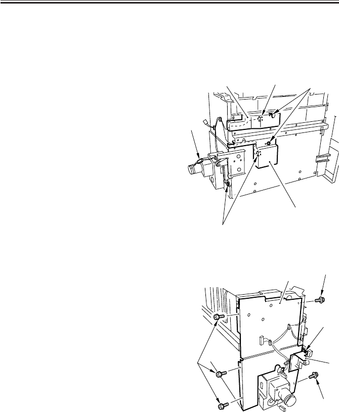
COPYRIGHT
©
2001 CANON INC. 2000 2000 2000 2000 CANON iR2200/iR2800/iR3300 REV.0 MAR. 2001
CHAPTER 8 PAPER DECK-L1
8-34 P
3.3.6 Removing the Lifter Cable (deck rear)
• Perform steps 1) through 3) under 3.3.5
“Removing the Lifter Cable (deck
front).” (p. 8-32P)
4) Remove the compartment. (p. 8-25P)
5) Remove the screw [1] (1 each), and de-
tach the sensor covers, upper [2] and
lower [3].
6) Disconnect the four connectors [4].
F08-303-08
7) Remove the screw [1], and detach the
sensor plate [2].
8) Remove the five screws [3], and detach
the plate [4].
F08-303-09
[1]
[4]
[2]
[3]
[4]
[4]
[3]
[1]
[2]
[4]
[3]
[3]
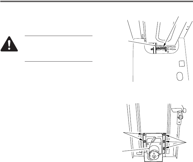
COPYRIGHT
©
2001 CANON INC. 2000 2000 2000 2000 CANON iR2200/iR2800/iR3300 REV.0 MAR. 2001
CHAPTER 8 PAPER DECK-L1
8-35 P
9) Fit a wrench [2] into the home of the
lifter drive shaft [1] to fix it in place
(against rotation).
If you fail to fix the lifter drive
shaft in place, the lifter cable
will become slack when the
lifter motor unit is removed.
F08-303-10
10) Remove the five screws [1], and detach
the lifter motor unit [2].
F08-303-11
[3]
[4]
[1]
[1]
[2]
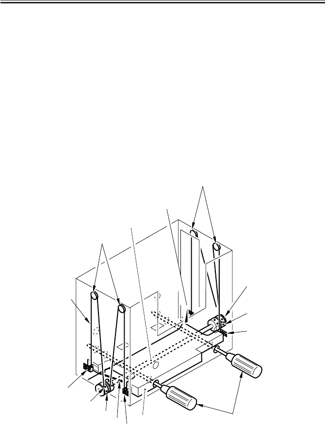
COPYRIGHT
©
2001 CANON INC. 2000 2000 2000 2000 CANON iR2200/iR2800/iR3300 REV.0 MAR. 2001
CHAPTER 8 PAPER DECK-L1
8-36 P
3.3.7 Routing the Lifter Cable
1) Check to make sure that the lifter drive shaft [1] and the lifter [2] are kept in place by
means of a hex wrench [3] and two long screwdrivers [4].
2) Fix the four cable fixing plates [5] in place to the lifter using two screws each.
3) Hook the lifter cable [6] on the four pulleys [7].
4) Hook the ball of the lifter cable on the two pulleys [8] at the front/rear of the lifter drive
shaft; then, wind it along the groove of the pulley about 1.5 turns. At this time, be sure
to keep the lifter cable taut so that the long screwdrivers used to keep the lifter in posi-
tion will move up and stop.
5) In this condition, secure the two pulleys [5] in place to the lifter drive shaft using a set
screw [9] (1 each).
6) Mount the pulleys [8] to the lifter drive shaft; then, measure the distance from the base
plate of the compartment to the top face of the lifter, making sure that the lifter is level.
F08-303-12
[4]
[8]
[9]
[5]
[7]
[7]
[5]
[1]
[2]
[5]
[9]
[8][3] [5]
[6]
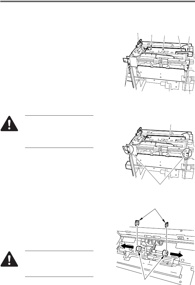
COPYRIGHT
©
2001 CANON INC. 2000 2000 2000 2000 CANON iR2200/iR2800/iR3300 REV.0 MAR. 2001
CHAPTER 8 PAPER DECK-L1
8-37 P
3.4 Feeding Mechanism
3.4.1 Removing the Deck Pickup Unit
1) Remove the upper cover. (p. 8-22P)
2) Remove the deck releasing grip [1].
3) Disconnect the two connectors [2], and
remove the five screws [3]; then, detach
the deck pickup unit [4].
F08-304-01
When mounting the deck
pickup unit [1], be sure to fit
and tighten the three screws [2]
indicated in the figure in ad-
vance.
F08-304-02
3.4.2 Removing the Deck Pickup Roller
1) Remove the deck pickup unit. (item
3.4.1)
2) Turn over the deck pickup unit, and re-
move the resin ring [1] (1 each); then,
detach the two deck pickup rollers [2].
The deck pickup roller has a
specific orientation (direction of
rotation). Pay attention to it
when mounting it.
F08-304-03
[2]
[3]
[3]
[3] [3] [1]
[4]
[1]
[2]
[2]
[1]
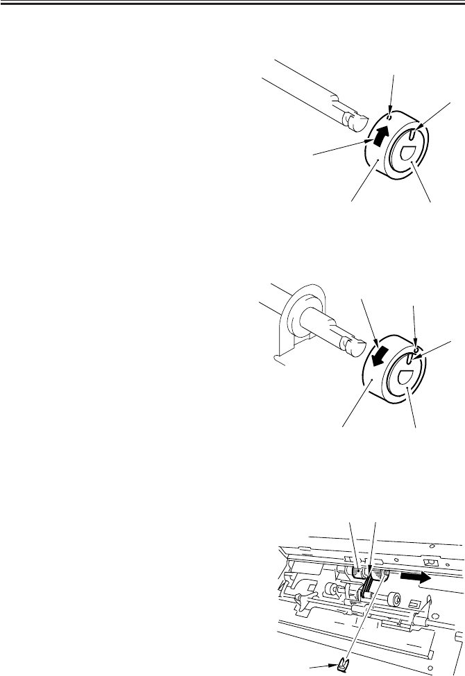
COPYRIGHT
©
2001 CANON INC. 2000 2000 2000 2000 CANON iR2200/iR2800/iR3300 REV.0 MAR. 2001
CHAPTER 8 PAPER DECK-L1
8-38 P
3.4.3 Mounting the Deck Pickup Roller
Body Front (collar: silver-colored)
When mounting the deck pickup roller
[2] to the front of the machine, be sure
that the marking [4] on the collar [3] is
toward the front of the machine and the
marking [5] on the side of the roller is to-
ward the rear of the machine.
F08-304-04
Body Rear (collar: gold-colored)
When mounting the deck pickup roller
[2] to the rear of the machine, be sure that
the marking [4] on the collar [3] and the
marking [5] on the side of the roller are
toward the rear of the machine.
F08-304-05
3.4.4 Removing the Deck Pickup/Feeding Roller
1) Remove the deck pickup unit. (p. 8-
37P)
2) Turn over the deck pickup unit.
3) Remove the resin ring [1], and detach
the deck pickup/feeding roller [2] and
the drive belt [3] to the front.
F08-304-06
[2] [3]
[3]
[3]
[1]
[4]
[5]
[1]
[2] [3]
[2] [3]
[1]
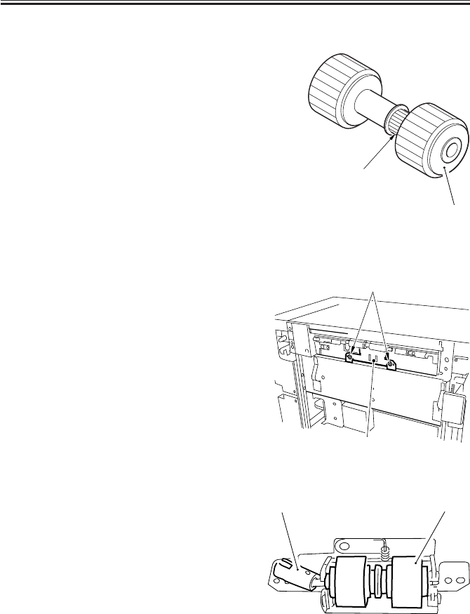
COPYRIGHT
©
2001 CANON INC. 2000 2000 2000 2000 CANON iR2200/iR2800/iR3300 REV.0 MAR. 2001
CHAPTER 8 PAPER DECK-L1
8-39 P
3.4.5 Orientation of the Deck Pickup/Feeding Roller
When mounting the deck pickup/feeding
roller [1], be sure that the belt pulley [2] is
toward the front of the machine.
The pickup/feeding roller rubber, on the
other hand, may be attached to the pickup/
feeding roller shaft in either orientation.
F08-304-07
3.4.6 Removing the Deck Separation Roller
1) Release the deck from its host machine;
then, remove the two screws [1], and
detach the separation roller support
plate [2].
F08-304-08
2) Remove the joint [1], and detach the
deck separation roller [2].
F08-304-09
[1]
[2]
[1]
[2]
[1] [2]
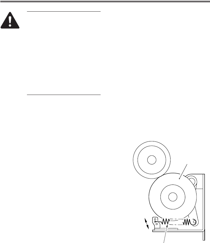
COPYRIGHT
©
2001 CANON INC. 2000 2000 2000 2000 CANON iR2200/iR2800/iR3300 REV.0 MAR. 2001
CHAPTER 8 PAPER DECK-L1
8-40 P
The urethane sponge used on
the deck separation roller is
pink upon foaming, and
changes over time to orange and
then yellow, accelerating the
rate of change if exposed to
light.
This is a general characteristic
of urethane sponge, and does
not affect its performance. (The
part is not offered in different
colors.)
3.4.7 Adjusting the Deck Separation Roller Pressure
If double feeding or pickup failure occurs
when the deck is used as the source of pa-
per, move the position of the pressure
spring [2] of the deck separation roller [1].
• If pickup failure occurs, move the
spring in the direction of arrow A.
• If double feeding occurs, move the
spring in the direction of arrow B.
F08-304-10
A
B
[1]
[2]
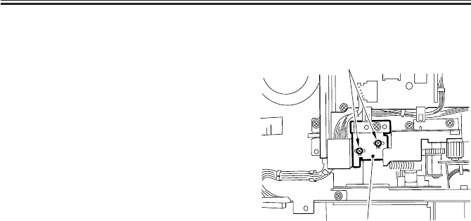
COPYRIGHT
©
2001 CANON INC. 2000 2000 2000 2000 CANON iR2200/iR2800/iR3300 REV.0 MAR. 2001
CHAPTER 8 PAPER DECK-L1
8-41 P
3.4.8 Position of the Deck Pickup Roller Releasing Solenoid (SL1D)
Before detaching the deck pickup roller
releasing solenoid [1] from the support
plate, keep note of the position of the sole-
noid with reference to the two fixing screws
[2] on the solenoid. Or, mark the position of
the solenoid on the support plate with a
scribe to indicate the position. The solenoid
must always be positioned in its initial loca-
tion.
F08-304-11
[1]
[2]
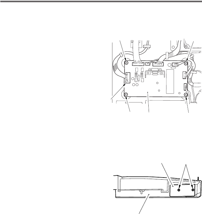
COPYRIGHT
©
2001 CANON INC. 2000 2000 2000 2000 CANON iR2200/iR2800/iR3300 REV.0 MAR. 2001
CHAPTER 8 PAPER DECK-L1
8-42 P
3.5 Electrical Mechanisms
3.5.1 Removing the Deck Drive PCB
1) Remove the rear cover. (p. 8-20P)
2) Disconnect the seven connectors [1],
and remove the four screws [2]; then,
detach the deck driver PCB [3].
F08-305-01
3.5.2 Removing the Open Switch PCB
1) Remove the front upper cover. (p. 8-
21P)
2) Remove the two screws [2] from behind
the front upper cover [1], and detach the
open switch PCB [3].
F08-305-02
[1]
[3]
[2] [2]
[2]
[2]
[3]
[1]
[2]

COPYRIGHT
©
2001 CANON INC. 2000 2000 2000 2000 CANON iR2200/iR2800/iR3300 REV.0 MAR. 2001
CHAPTER 9
CASSETTE FEEDING UNIT-W1

COPYRIGHT
©
2001 CANON INC. 2000 2000 2000 2000 CANON iR2200/iR2800/iR3300 REV.0 MAR. 2001
CHAPTER 9 CASSETTE FEEDING UNIT-W1
9-1 P
1 Outline
1.1 Specifications and Construction
T09-101-01 shows the major functions and the construction of the Cassette Feeding unit-
W1:
Item Description Remarks
Storage of paper Front loading
Method of pickup Retard
Cassette 2 (cassettes 3, 4) The cassette 3 (4) is in common
with the cassette 1 (2) of the
host machine.
Switching of size By user
Type of paper Plain paper, recycled paper
(64 to 90 g/m2)
Size of paper A5/STMT to A3/11 × 17 For the cassette 3, A5/STMT to
(279mm × 432mm) B4 (LGL) max.
Size of source 500 × 2 = 1000 sheets (of 80 g/m2
paper; if 64 g/m2, 550 × 2)
Control panel No (keys on host machine used)
Display No (keys on host machine used)
Environmental No A cassette heater (accessory) may
considerations be fitted.
Power supply No (24 VDC/5 V supplied by main
power supply of host machine)
Dimensions 565 (W) × 678 (D) × 248 (H) mm /
22.2 (W) × 26.7 (D) × 9.76 (H) inches
Weight 28 kg / 61.7 lb
Operating noise 3 dB or less + that of host machine
T09-101-01
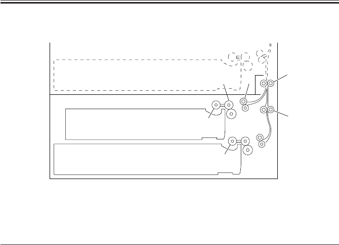
COPYRIGHT
©
2001 CANON INC. 2000 2000 2000 2000 CANON iR2200/iR2800/iR3300 REV.0 MAR. 2001
CHAPTER 9 CASSETTE FEEDING UNIT-W1
9-2 P
1.2 Arrangement of Rollers
F09-102-01
The following rollers are used to move paper inside the machine:
Notation Name
[1] Pickup roller
[2] Feeding roller
[3] Separation roller
[4] Pull-off roller
[5] Vertical path roller
[1]
[1]
[2]
[2] [4]
[5]
[5]
[4]
[3]
[3]
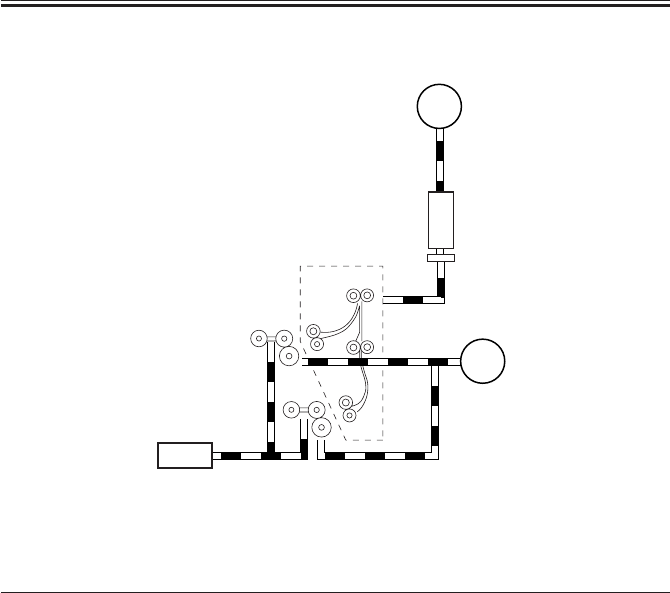
COPYRIGHT
©
2001 CANON INC. 2000 2000 2000 2000 CANON iR2200/iR2800/iR3300 REV.0 MAR. 2001
CHAPTER 9 CASSETTE FEEDING UNIT-W1
9-3 P
1.3 Arrangement of Motors, Clutches, and Solenoids
F09-103-01
The following motors, clutch, and solenoid are used to move paper inside the machine:
Notation Name
M1C Pedestal main motor
M2C Cassette pickup motor
CL1C Vertical path roller clutch
SL1C Pickup roller descent solenoid
M1C
CL1C
SL1C
M2C
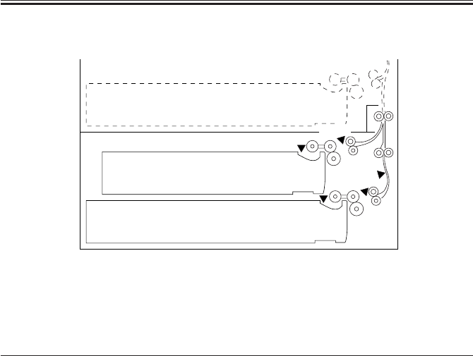
COPYRIGHT
©
2001 CANON INC. 2000 2000 2000 2000 CANON iR2200/iR2800/iR3300 REV.0 MAR. 2001
CHAPTER 9 CASSETTE FEEDING UNIT-W1
9-4 P
1.4 Arrangement of Sensors
F09-104-01
The following sensors are used to monitor the movement of paper:
Notation Name Delay jam Stationary jam Stationary jam
at power-on
Q1604 Cassette 3 paper sensor No No No
Q1605 Cassette 4 paper sensor No No No
PS2C Cassette 3 re-try paper sensor Yes No No
PS3C Cassette 4 re-try paper sensor Yes No No
Q1603 Vertical path paper sensor Yes No No
Q1603
Q1604
PS3C
Q1605
PS2C

COPYRIGHT
©
2001 CANON INC. 2000 2000 2000 2000 CANON iR2200/iR2800/iR3300 REV.0 MAR. 2001
CHAPTER 9 CASSETTE FEEDING UNIT-W1
9-5 P
2 Detecting Jams
2.1 Sequence of Jam Detection
2.1.1 Delay Jams
See the descriptions under “Pickup/Feeding System” in Chapter 5.
2.1.2 Stationary Jams
See the descriptions under “Pickup/Feeding System” in Chapter 5.
2.1.3 Jam History
See the descriptions under “Pickup/Feeding System” in Chapter 5.
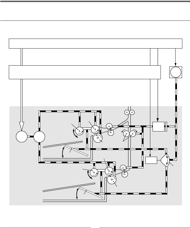
COPYRIGHT
©
2001 CANON INC. 2000 2000 2000 2000 CANON iR2200/iR2800/iR3300 REV.0 MAR. 2001
CHAPTER 9 CASSETTE FEEDING UNIT-W1
9-6 P
3 Pickup Assembly
3.1 Pickup Control System
F09-301-01
M2C
M1C
CL1C
[8]
SL1C
[2]
[4]
[3]
[2]
[4]
[5]
[5]
[3]
[7]
[6]
[9]
[1]
Notation Name
[1] Gear
[2] Pickup roller
[3] Feeding roller
[4] Separation roller
[5] Lifter
[6] Vertical path roller
[7] Cam
Notation Name
[8] Pedestal controller PCB
[9] Cassette pickup PCB
M1C Main motor
M2C Pickup motor
CL1C Vertical path clutch
SL1C Pickup descent solenoid

COPYRIGHT
©
2001 CANON INC. 2000 2000 2000 2000 CANON iR2200/iR2800/iR3300 REV.0 MAR. 2001
CHAPTER 9 CASSETTE FEEDING UNIT-W1
9-7 P
3.2 Outline
See the descriptions under “Pickup/Feeding System” in Chapter 5.
3.3 Sequence of Operations (pickup)
See the descriptions under “Pickup/Feeding System” in Chapter 5.
3.4 Operation of the Cassette Lifter
See the descriptions under “Pickup/Feeding System” in Chapter 5.
3.5 Cassette Pickup Operation
See the descriptions under “Pickup/Feeding System” in Chapter 5.
3.6 Moving Up/Down the Pickup Roller
See the descriptions under “Pickup/Feeding System” in Chapter 5.
3.7 Detecting the Presence/Absence of Paper Inside the Cas-
sette
See the descriptions under “Pickup/Feeding System” in Chapter 5.
3.8 Pickup ReTry Operation
See the descriptions under “Pickup/Feeding System” in Chapter 5.
3.9 Operation Other Than Cassette Pickup (standby)
See the descriptions under “Pickup/Feeding System” in Chapter 5.
3.10 Detecting the Level of Paper
See the descriptions under “Pickup/Feeding System” in Chapter 5.

COPYRIGHT
©
2001 CANON INC. 2000 2000 2000 2000 CANON iR2200/iR2800/iR3300 REV.0 MAR. 2001
CHAPTER 9 CASSETTE FEEDING UNIT-W1
9-8 P
4 Identifying the Size of Paper
4.1 Identifying the Size
See the descriptions under “Pickup/Feeding System” in Chapter 5.
4.2 AB/Inch-Setting Switch
See the descriptions under “Pickup/Feeding System” in Chapter 5.
4.3 Paper Size
See the descriptions under “Pickup/Feeding System” in Chapter 5.

COPYRIGHT
©
2001 CANON INC. 2000 2000 2000 2000 CANON iR2200/iR2800/iR3300 REV.0 MAR. 2001
CHAPTER 9 CASSETTE FEEDING UNIT-W1
9-9 P
5 Disassembly and Assembly
The discussions that follow cover the machine’s mechanical characteristics and how to
disassemble/assemble the machine. Keep the following in mind whenever you work with the
machine:
1. The power plug must remain disconnected for safety when disassembling/assembling
the machine.
2. Unless otherwise noted, the machine may be assembled by reversing the steps used to
disassemble it.
3. The screws must be identified by type (length, diameter) and location.
4. The mounting screws used for the grounding wire and the varistors come with a washer,
which must not be left out when assembling the machine.
5. As a rule, the machine must not be operated with any of its parts removed.
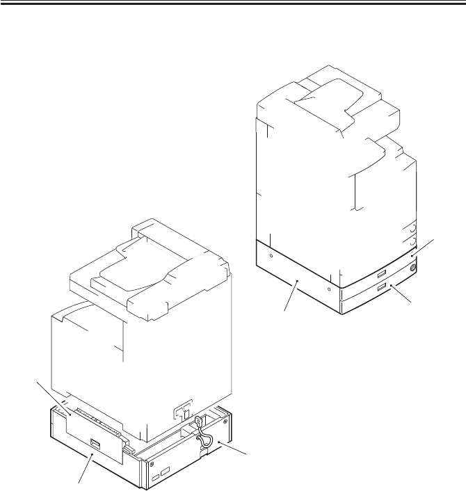
COPYRIGHT
©
2001 CANON INC. 2000 2000 2000 2000 CANON iR2200/iR2800/iR3300 REV.0 MAR. 2001
CHAPTER 9 CASSETTE FEEDING UNIT-W1
9-10 P
5.1 External Covers
F09-501-01
[1]
[2]
[3]
[4]
[5]
[6]
[1] Cassette 3
[2] Cassette 3
[3] Pickup cover
[4] Right cover (2 screws)
[5] Rear cover (2 screws)
[6] Left cover

COPYRIGHT
©
2001 CANON INC. 2000 2000 2000 2000 CANON iR2200/iR2800/iR3300 REV.0 MAR. 2001
CHAPTER 9 CASSETTE FEEDING UNIT-W1
9-11 P
5.1.1 Removing the Pickup Cover
1) Open the pickup cover [1].
2) Open the vertical path assembly [2], and
disconnect the connector [3].
F09-501-02
3) With the vertical path assembly [1]
open, shift the rear support shaft [2] to
the right and the front support shaft [3]
to the rear to detach the vertical path as-
sembly.
F09-501-03
4) Remove the cable [2] from the front
support shaft [1].
5) Shift down the pickup cover [3], and
detach it to the right.
F09-501-04
[1]
[2]
[3]
[3]
[1]
[2]
[1]
[2]
[3]

COPYRIGHT
©
2001 CANON INC. 2000 2000 2000 2000 CANON iR2200/iR2800/iR3300 REV.0 MAR. 2001
CHAPTER 9 CASSETTE FEEDING UNIT-W1
9-12 P
5.2 Pickup Assembly
5.2.1 Removing the Pickup Assembly
1) Remove the cassette 3/4.
2) Remove the pickup cover. (p. 9-11P)
3) Remove the rear cover of the host ma-
chine. (7 screws; p. 7-13P)
4) Remove the right rear cover of the host
machine. (5 screws; p. 7-13P)
5) Remove the right cover. (2 screws)
6) Remove the screw [1], and disconnect
the connector [2]; then, detach the har-
ness unit.
F09-502-01
7) Remove the seven screws [1], and de-
tach the right support plate [2].
8) Disconnect the connector [3].
9) Remove the screw [4], and detach the
grounding wire [5].
10) Remove the four screws [6], and detach
the pickup unit [7].
F09-502-02
[1]
[2]
[3]
[6]
[3]
[4]
[5]
[1]
[2] [1] [6]
[1]
[1]
[6]
[7]

COPYRIGHT
©
2001 CANON INC. 2000 2000 2000 2000 CANON iR2200/iR2800/iR3300 REV.0 MAR. 2001
CHAPTER 9 CASSETTE FEEDING UNIT-W1
9-13 P
5.2.2 Removing the Pickup/Feeding/Separation Roller
See “Pickup/Feeding System” in Chapter 5-9.1.2.
5.2.3 Removing the Pickup Soleroid
See “Pickup/Feeding System” in Chapter 5-9.1.3.
5.2.4 Removing the Frame Lid
See “Pickup/Feeding System” in Chapter 5-9.1.4.
5.2.5 Removing the Pickup Motor
See “Pickup/Feeding System” in Chapter 5-9.1.5.
5.2.6 Removing the Vertical Path Clutch
See “Pickup/Feeding System” in Chapter 5-9.1.6.
5.2.7 Adjusting the Registration for the Cassette Rear Front
See “Pickup/Feeding System” in Chapter 5-9.1.8.
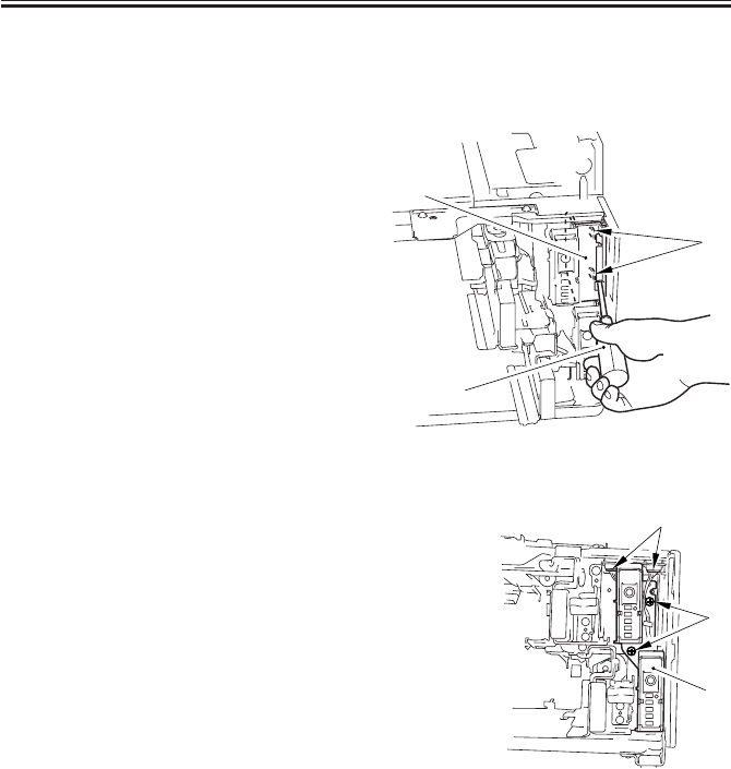
COPYRIGHT
©
2001 CANON INC. 2000 2000 2000 2000 CANON iR2200/iR2800/iR3300 REV.0 MAR. 2001
CHAPTER 9 CASSETTE FEEDING UNIT-W1
9-14 P
5.3 PCBs
5.3.1 Removing the Cassette Size Detection Unit
1) Remove the cassette 3/4.
2) Fit a flat-blade screwdriver [2] into the
opening in the inner cover [1], and free
the two claws [3] to detach.
F09-503-01
3) Remove the two screws [1], and slide
the cassette size detection unit [2] to the
front to detach.
4) Disconnect the two connectors [3].
5) Remove the cassette size detection unit.
F09-503-02
[2]
[1]
[3]
[1]
[2]
[3]
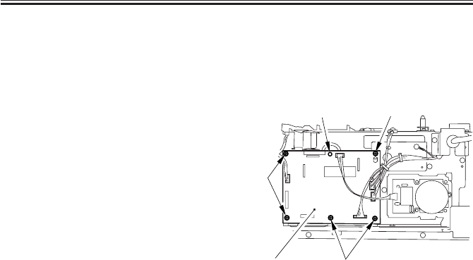
COPYRIGHT
©
2001 CANON INC. 2000 2000 2000 2000 CANON iR2200/iR2800/iR3300 REV.0 MAR. 2001
CHAPTER 9 CASSETTE FEEDING UNIT-W1
9-15 P
5.3.2 Removing the Pedestal Controller PCB
1) Disconnect the lattice connector from
the host machine.
2) Remove the rear over. (2 screws)
3) Disconnect all the connectors.
4) Release the locking support [1].
5) Remove the five screws [2], and detach
the pedestal controller PCB [3].
F09-503-03
[2]
[2]
[3]
[1] [2]
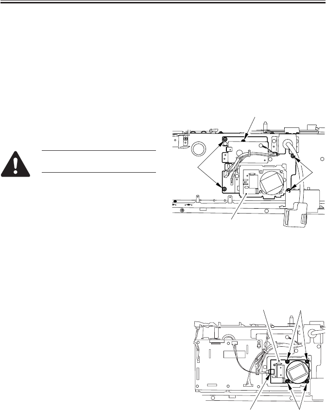
COPYRIGHT
©
2001 CANON INC. 2000 2000 2000 2000 CANON iR2200/iR2800/iR3300 REV.0 MAR. 2001
CHAPTER 9 CASSETTE FEEDING UNIT-W1
9-16 P
5.4 Drive Mechanisms
5.4.1 Removing the Main Motor Drive Unit
1) Disconnect the lattice connector from
the host machine.
2) Remove the pickup assembly. (p. 9-
12P)
3) Remove the rear cover. (2 screws)
4) Remove the pedestal controller PCB. (p.
9-15P)
5) Remove the four screws [1], and detach
the main motor drive unit [2].
Do not remove the screw [3]
paint-locked in place.
F09-504-01
5.4.2 Removing the Pedestal Main Motor
1) Disconnect the lattice connector from
the host machine.
2) Remove the rear cover. (2 screws)
3) Disconnect the connector [1].
4) Remove the four screws [2], and detach
the pedestal main motor [3].
F09-504-02
[1] [1]
[2]
[3]
[1]
[2]
[2]
[3]

COPYRIGHT
©
2001 CANON INC. 2000 2000 2000 2000 CANON iR2200/iR2800/iR3300 REV.0 MAR. 2001
CHAPTER 9 CASSETTE FEEDING UNIT-W1
9-17 P
5.4.3 Mounting the Pedestal Main Motor
1) When mounting the pedestal main mo-
tor, be sure to tighten the screws in the
order indicated in the figure: (1)
through (4).
F09-504-03
(1) (4)
(2)
(3)

COPYRIGHT
©
2001 CANON INC. 2000 2000 2000 2000 CANON iR2200/iR2800/iR3300 REV.0 MAR. 2001
CHAPTER 10
INNER 2 WAY TRAY-A1
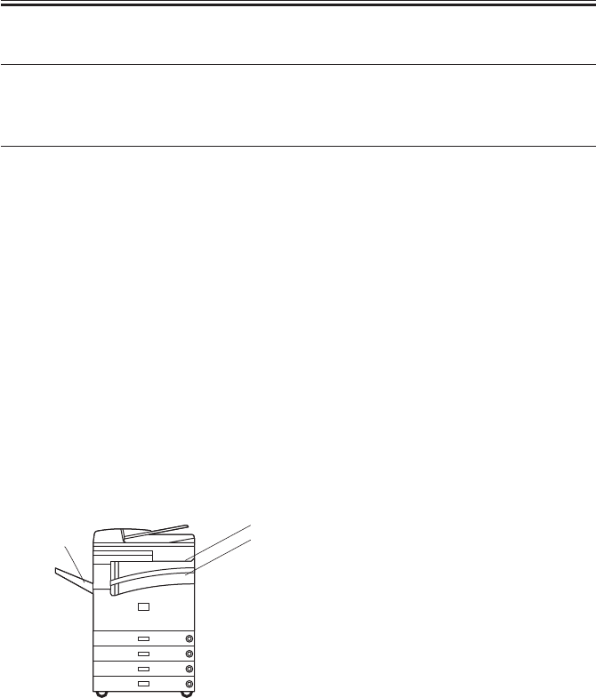
COPYRIGHT
©
2001 CANON INC. 2000 2000 2000 2000 CANON iR2200/iR2800/iR3300 REV.0 MAR. 2001
CHAPTER 10 INNER 2 WAY TRAY-A1
10-1 P
1 Specifications
1.1 Type
Item Description
Number of bins 3 in total
1 bin (No. 2 delivery slot)
Delivery tray inside host machine
External (No. 3 delivery slot; option)
Method of stacking Face-down
Type of paper Plain paper, recycled paper (between 64 g/m2 and 90 g/m2)
Size of paper A3/279.4×431.8mm (11"×17") to A5/STMT
Number of sheets (No. 2 delivery slot) 250 sheets (A4, B5, LTR); 100 sheets (other sizes)
Number of sheets (No. 3 delivery slot) 100 sheets (A4, B5, LTR); 50 sheets (other sizes)
Environmental considerations None in particular
Power supply None
Dimensions 149×420×254mm/5.87 in.×16.5 in.×10 in. (W×D×H)
Weight 3.5kg/7.7 lb
T10-101-01
Tray names
Without the Saddle Finisher-G1
F10-101-01
CA
B
A: No 1 delivery slot (host machine)
B: No. 2 delivery slot
C: No. 3 delivery slot (Copy Tray-F1/
Saddle Finisher-G1)
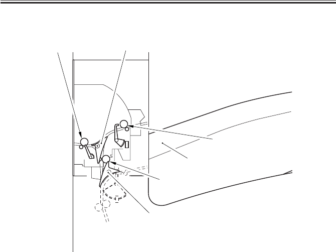
COPYRIGHT
©
2001 CANON INC. 2000 2000 2000 2000 CANON iR2200/iR2800/iR3300 REV.0 MAR. 2001
CHAPTER 10 INNER 2 WAY TRAY-A1
10-2 P
1.2 Cross Section
F10-102-01
[2]
[5]
[3]
[6]
[4]
[1]
[1] No. 3 delivery roller
[2] No. 3 delivery flapper
[3] No. 2 delivery roller
[4] Tray B
[5] No. 2 delivery inlet roller
[6] No. 2 deliver inlet flapper

COPYRIGHT
©
2001 CANON INC. 2000 2000 2000 2000 CANON iR2200/iR2800/iR3300 REV.0 MAR. 2001
CHAPTER 10 INNER 2 WAY TRAY-A1
10-3 P
2 Outline
2.1 Arrangement of Rollers and Sensors
F10-201-01
M8
M7
PS24B
No. 1 delivery slot
No. 2 delivery slot
SL4
M7: 2-way delivery inlet motor
M8: 2-way delivery outlet motor
SL4: 2-way delivery solenoid
PS19B: No. 2 delivery sensor
PS20B: No. 2 delivery full sensor
PS21B: No. 3 delivery sensor
PS4B: 2-way delivery open/closed sensor
No. 3 delivery roller No. 3 delivery flapper
No. 2 delivery inlet roller
No. 2 delivery roller
No. 2 delivery inlet flapper
PS20B
PS19B
No. 3
delivery slot
PS21B
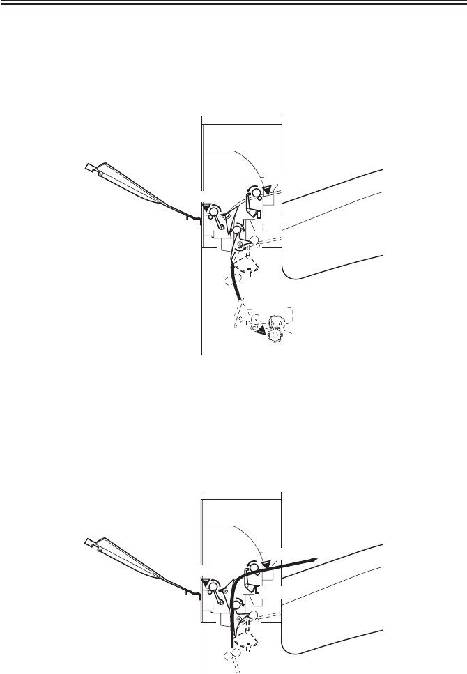
COPYRIGHT
©
2001 CANON INC. 2000 2000 2000 2000 CANON iR2200/iR2800/iR3300 REV.0 MAR. 2001
CHAPTER 10 INNER 2 WAY TRAY-A1
10-4 P
2.2 Delivery to the No. 2 Delivery Slot
Sheets are sent to the No. 2 delivery slot as follows:
1) A sheet arrives from the host machine’s delivery assembly. A specific period of
time after the leading edge of the sheet reaches the fixing/feeding sensor (PS13), the 2-
way delivery inlet motor (M7) and the 2-way delivery outlet motor (M8) start to rotate.
F10-202-01
2) The 2-way delivery solenoid goes on, and the paper switches to the No. 2
delivery slot. Then, the 2-way delivery inlet motor and the 2-way delivery outlet motor
continue to rotate to send the sheet to the No. 2 delivery slot.
When the trailing edge of the sheet leaves the No. 2 delivery sensor (PS19B), the 2-way
delivery inlet motor and the 2-way delivery outlet motor stop to rotate.
F10-202-02
S14
PS21B
No. 1 delivery slot
No. 2 delivery slot
PS20B
PS19B
No. 3
delivery slot
PS13
S14
PS21B
PS20B
PS19B
No. 3
delivery slot
No. 2 delivery slot
No. 1 delivery slot
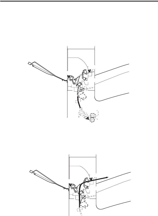
COPYRIGHT
©
2001 CANON INC. 2000 2000 2000 2000 CANON iR2200/iR2800/iR3300 REV.0 MAR. 2001
CHAPTER 10 INNER 2 WAY TRAY-A1
10-5 P
2.3 Delivery to the No. 3 Delivery Slot
Sheets are sent to the No. 3 delivery slot as follows:
1) A sheet arrives from the host machine’s delivery assembly. A specific period of
time after the leading edge of the sheet reaches the fixing/delivery paper sensor (PS13),
the 2-way delivery inlet motor (M7) and the 2-way delivery outlet motor (M8) start to
rotate.
F10-203-01
2) The 2-way delivery solenoid goes on, and the feeding path switches to the No.
2 delivery lot.
F10-203-02
S14
PS21B
PS20B
PS19B
PS13
No. 3
delivery slot
No. 2 delivery slot
No. 1 delivery slot
S14
PS21B
PS20B
PS19B
No. 3
delivery slot
No. 2 delivery slot
No. 1 delivery slot
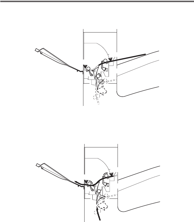
COPYRIGHT
©
2001 CANON INC. 2000 2000 2000 2000 CANON iR2200/iR2800/iR3300 REV.0 MAR. 2001
CHAPTER 10 INNER 2 WAY TRAY-A1
10-6 P
3) When the trailing edge of the sheet reaches a specific point in front of the No. 2
delivery roller, the 2-way delivery outlet motor stops to rotate.
F10-203-03
4) A specific period of time after it stops to rotate, the 2-way delivery outlet motor
starts to rotate in reverse, thereby sending the sheet to the No. 3 delivery slot.
F10-203-04
S14
PS21B
PS20B
PS19B
No. 3
delivery slot
No. 2 delivery slot
No. 1 delivery slot
S14
PS21B
PS20B
PS19B
No. 3
delivery slot
No. 2 delivery slot
No. 1 delivery slot
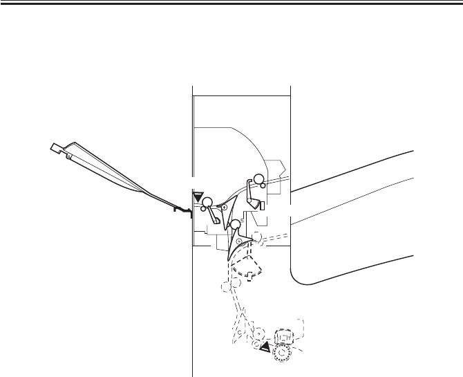
COPYRIGHT
©
2001 CANON INC. 2000 2000 2000 2000 CANON iR2200/iR2800/iR3300 REV.0 MAR. 2001
CHAPTER 10 INNER 2 WAY TRAY-A1
10-7 P
2.4 Detecting Jams
2.4.1 Arrangement of Sensors
The following shows the sensor used to detect jams in the Inner 2-Way-A1.
F10-204-01
PS21B
PS19B
PS13
PS19B: No. 2 delivery sensor
PS21B: No. 3 delivery sensor
PS24B: 2-way delivery open/closed sensor
PS13: fixing/feeding sensor (host machine)
No. 3
delivery slot
No. 2 delivery slot
No. 1 delivery slot
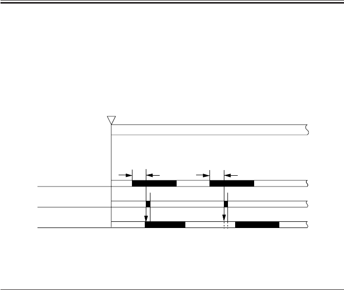
COPYRIGHT
©
2001 CANON INC. 2000 2000 2000 2000 CANON iR2200/iR2800/iR3300 REV.0 MAR. 2001
CHAPTER 10 INNER 2 WAY TRAY-A1
10-8 P
2.4.2 Delay Jam
The time it takes for a sheet to move from the sensor N-1 to the delay jam sensor N is
monitored with reference to the clock pulses from the main motor. A delay jam is identified
if the leading edge of a sheet does not reach the delay jam sensor within a specific period of
time after the senor N-1 goes ON.
F10-204-02
Notation Name Delay jam
PS13 Fixing/feeding sensor (host machine) (yes)
PS119B No. 2 delivery sensor Yes
PS20B No. 3 delivery sensor Yes
Start key ON
or
PRINT set
INTR / PRINT
Sensor N-1
Jam check
Sensor N Normal Error
[1] [1]
[1]: specific feeding time
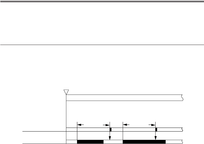
COPYRIGHT
©
2001 CANON INC. 2000 2000 2000 2000 CANON iR2200/iR2800/iR3300 REV.0 MAR. 2001
CHAPTER 10 INNER 2 WAY TRAY-A1
10-9 P
2.4.3 Stationary Jam
A stationary jam will be identified if a specific sensor remains ON for a specific period of
time.
Notation Name Stationary jam
PS19B No. 2 delivery sensor Yes
PS20B No. 3 delivery sensor Yes
F10-204-03
2.4.4 Stationary Jam at Power-On
A stationary jam at power-on is identified in reference to the presence/absence of paper
over a specific period of time cover a specific sensor when the control panel power switch is
turned on.
2.4.5 Door Open Jam
A door open jam will be identified if the 2-way delivery open/closed sensor (PS24B)
identifies the state of the door as being open.
Start key ON
or
PRINT set
INTR / PRINT
Jam check
Sensor N
L + A
Normal Error
L + A
(L: paper length; A: specific feed distance)

COPYRIGHT
©
2001 CANON INC. 2000 2000 2000 2000 CANON iR2200/iR2800/iR3300 REV.0 MAR. 2001
CHAPTER 10 INNER 2 WAY TRAY-A1
10-10 P
3 Disassembly and Assembly
The discussions that follow cover the machine’s mechanical characteristics and how to
disassemble/assemble the machine. Keep the following in mind whenever you work with the
machine:
1. The power plug must remain disconnected for safety when disassembling/assembling
the machine.
2. Unless otherwise noted, the machine may be assembled by reversing the steps used to
disassemble it.
3. The screws must be identified by type (length, diameter) and location.
4. The mounting screws used for the grounding wire and the varistors come with a washer,
which must not be left out when assembling the machine.
5. As a rule, the machine must not be operated with any of its parts removed.
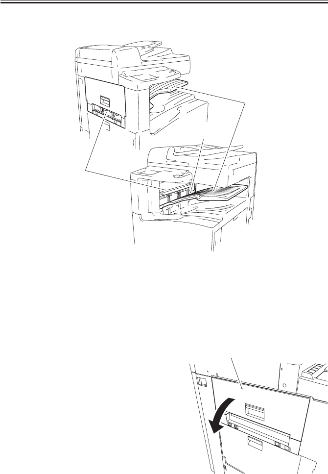
COPYRIGHT
©
2001 CANON INC. 2000 2000 2000 2000 CANON iR2200/iR2800/iR3300 REV.0 MAR. 2001
CHAPTER 10 INNER 2 WAY TRAY-A1
10-11 P
3.1 External Covers
F10-301-01
[1] Inner 2-way delivery unit (2 screws)
[2] Inside delivery tray
[3] Connector cover (1 screw)
3.1.1 Removing the Inner 2-Way Delivery Unit
1) Remove the inside delivery tray.
2) Open the inner 2-way delivery unit [1].
F10-301-02
[1]
[2]
[3]
[1]
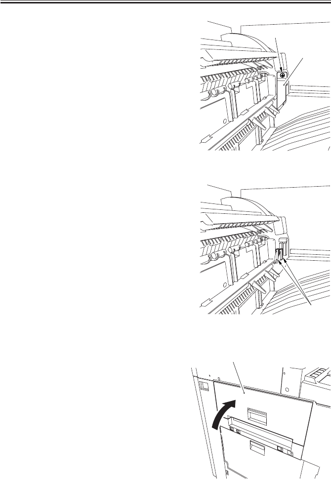
COPYRIGHT
©
2001 CANON INC. 2000 2000 2000 2000 CANON iR2200/iR2800/iR3300 REV.0 MAR. 2001
CHAPTER 10 INNER 2 WAY TRAY-A1
10-12 P
3) Remove the screw [1], and detach the
connector cover [2].
F10-201-03
4) Disconnect the two connectors [1].
F10-201-04
5) Close the inner 2-way delivery unit [1].
F10-201-05
[2]
[1]
[1]
[1]
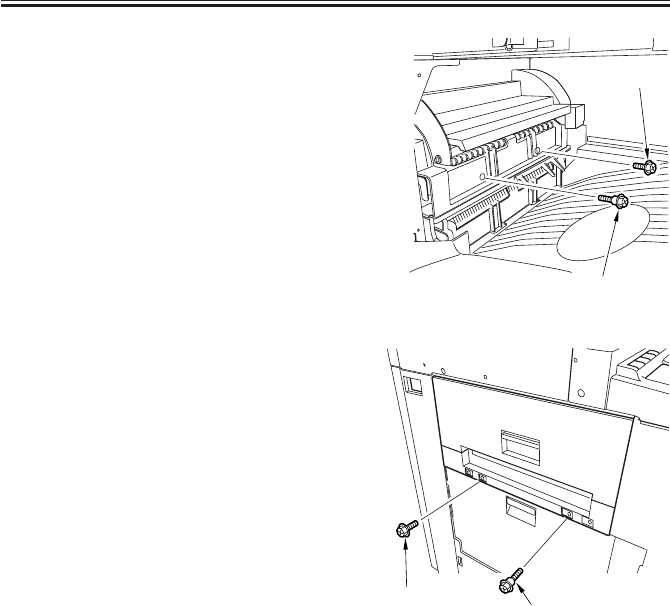
COPYRIGHT
©
2001 CANON INC. 2000 2000 2000 2000 CANON iR2200/iR2800/iR3300 REV.0 MAR. 2001
CHAPTER 10 INNER 2 WAY TRAY-A1
10-13 P
6) Remove the screw [1] and the stepped
screw [2] from inside.
F10-201-06
7) Remove the screw [1] and the stepped
screw [2] from outside.
F10-201-07
[1]
[2]
[1] [2]
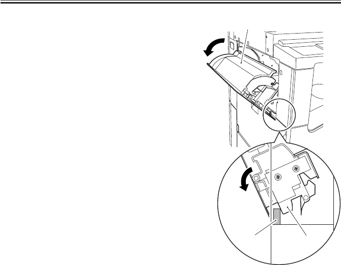
COPYRIGHT
©
2001 CANON INC. 2000 2000 2000 2000 CANON iR2200/iR2800/iR3300 REV.0 MAR. 2001
CHAPTER 10 INNER 2 WAY TRAY-A1
10-14 P
8) Remove the rib [2] from the stay [1] of
the host machine, and remove the inner
2-way delivery unit [3].
F10-201-08
[3]
[2]
[1]

COPYRIGHT
©
2001 CANON INC. 2000 2000 2000 2000 CANON iR2200/iR2800/iR3300 REV.0 MAR. 2001
CHAPTER 11
ENVELOPE FEEDER ATTACHMENT-B1
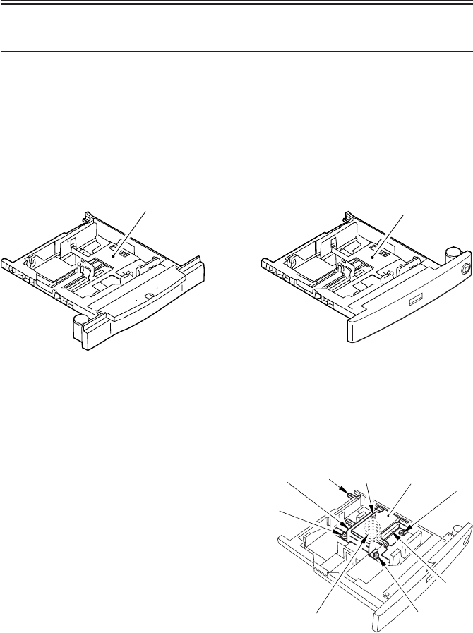
COPYRIGHT
©
2001 CANON INC. 2000 2000 2000 2000 CANON iR2200/iR2800/iR3300 REV.0 MAR. 2001
CHAPTER 11 ENVELOPE FEEDER ATTACHMENT-B1
11-1 P
1 Envelope Feeder Attachment-B1
1.1 Outline
The Envelope Feeder Attachment-B1 (hereafter, envelope feeder) is designed to be in-
stalled to the cassette 1 of the host machine for feeding of envelopes; its pickup mechanisms
are in common with those of the cassette 1.
1.1.1 Host Machine
The cassette 1 for which the envelope feeder is designed may be either of the following
two:
F11-101-01 F11-101-02
[1] GP Cassette-N1
[2] FL Cassette-V1
1.1.2 Names of Parts
[1] Side guide plate (front)
[2] Side guide plate (rear)
[3] Lifter
[4] Lifter stop
[5] Mounting screw (4 pc.)
[6] Spring (2 pc. including attachment)
F11-101-03
[1]
[2]
[6] [5]
[1]
[5]
[5] [5]
[3]
[4]
[2]

COPYRIGHT
©
2001 CANON INC. 2000 2000 2000 2000 CANON iR2200/iR2800/iR3300 REV.0 MAR. 2001
CHAPTER 11 ENVELOPE FEEDER ATTACHMENT-B1
11-2 P
1.2 Specifications
1.2.1 Envelope Cassette
Item Description Remarks
Method of pickup Front loading
Reference of paper movement Center
Switching of size In user mode By user.
By cassette side plate By user.
By spring By service person.
(to suit envelope size)
Size of stack As determined by T11-102-02
envelope specifications
Maximum number of envelopes 10 to 6CPM The stack must not exceed the
label index (with envelope
YOUKEI 4 in use; decrease in
speed occurring in continuous
feed).
Control panel/display No Uses that of the host machine.
Power supply No
Dimensions 565(W)×523(D)×95(H)mm /
22.2(W)×20.6(D)×3.74(W)inches
Weight 3.4 kg / 7.5 lb
Operating environment As determined by host machine
T11-102-01
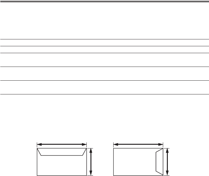
COPYRIGHT
©
2001 CANON INC. 2000 2000 2000 2000 CANON iR2200/iR2800/iR3300 REV.0 MAR. 2001
CHAPTER 11 ENVELOPE FEEDER ATTACHMENT-B1
11-3 P
1.2.2 Envelopes
The envelope feeder is designed to accommodate envelopes of the following specifica-
tions:
Type Shorter side (X) × longer side (Y) Recommendation
COM10 104.7 × 241.3 (mm) Mailwell No.553
Monarch 98.4 × 190.5 (mm) Mailwell No.582
DL 110 × 220 (mm) Mailwell
Schneidersohne No.11345
C5 162 × 229 (mm) Schneidersohne Kuvert
No.17204
B5 176 × 250 (mm) Schneidersohne Kuvert
No.15269
YOUKEI 4 105 × 235 (mm) Y-401
T11-102-02
Configuration of Envelopes
F11-102-01
COM10, Monarch, DL
C5, YOUKEI 4
Y
X
Y
B5
X
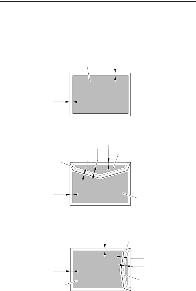
COPYRIGHT
©
2001 CANON INC. 2000 2000 2000 2000 CANON iR2200/iR2800/iR3300 REV.0 MAR. 2001
CHAPTER 11 ENVELOPE FEEDER ATTACHMENT-B1
11-4 P
1.2.3 Guaranteed Image Area
The guaranteed image area is 10 mm or more from each edge of the envelope; if triple-
layered because of the flap, within 5 mm or more.
The figures show the guarantee image area (area B); they assume that the triple-layered
area because of the flap is limited to area A:
• Face of the Envelope (common)
F11-102-02
• Back of the Envelope (COM10, Monarch, D, C5, YOUKEI 4)
F11-102-03
• Back of the Envelope (B5)
F11-102-04
10mm
10mm
B
10mm
10mm
B
B
A
5mm
5mm
10mm
10mm
BB
A
5mm
5mm

COPYRIGHT
©
2001 CANON INC. 2000 2000 2000 2000 CANON iR2200/iR2800/iR3300 REV.0 MAR. 2001
CHAPTER 11 ENVELOPE FEEDER ATTACHMENT-B1
11-5 P
1.3 Pickup
1.3.1 Pickup Operations
In place of the cassette lifter operation of the host machine, the envelope cassette uses the
force of a spring to keep the stack at a specific level; other operations are as in the pickup/
feeding operations of the host machine.

COPYRIGHT
©
2001 CANON INC. 2000 2000 2000 2000 CANON iR2200/iR2800/iR3300 REV.0 MAR. 2001
CHAPTER 11 ENVELOPE FEEDER ATTACHMENT-B1
11-6 P
2 Detecting Jams
2.1 Outline
There are no specific types of jams that are unique to the envelope feeder, and jams are
detected as by the jam detection mechanism of the host machine.
3 Error Codes
3.1 Outline
There are no specific types of jams unique to the envelope cassette, and error codes are
issued as by the error detection mechanism of the host machine.
4 Service Mode
4.1 Making Selections
*5*OPTION ENV_SW
1: enable
2: disable (the key ‘select envelope cassette’ offered as part of common settings in user
mode will be dimmed)
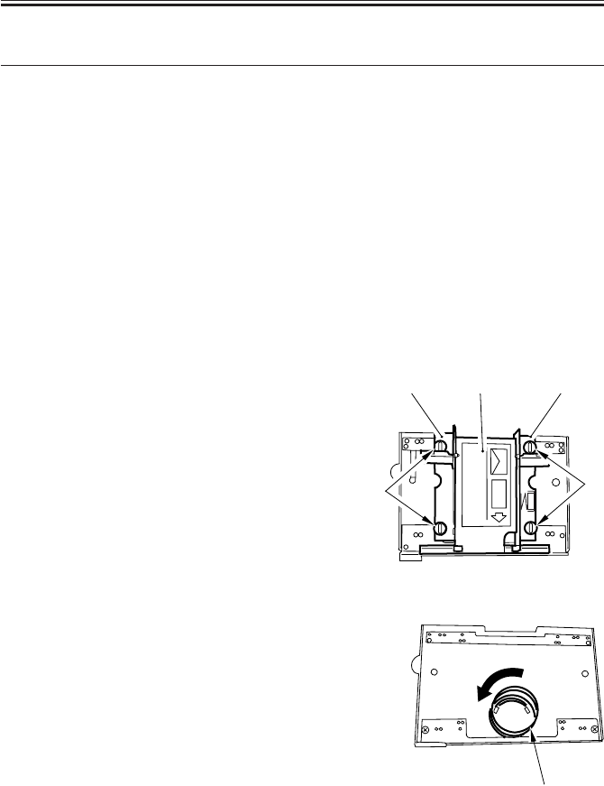
COPYRIGHT
©
2001 CANON INC. 2000 2000 2000 2000 CANON iR2200/iR2800/iR3300 REV.0 MAR. 2001
CHAPTER 11 ENVELOPE FEEDER ATTACHMENT-B1
11-7 P
5 Making Adjustments
5.1 Outline
If you want to use envelopes with a different configuration in the envelope feeder, you
need to replace the spring to suit the new envelope.
The spring may be painted either green or red; one is already fitted, and the other is ex-
pected to be stored by the user near the host machine.
Be sure to check that the correct spring is fitted whenever you want to switch to envelopes
of a different configuration.
5.1.1 Envelopes and Type of Spring
• Use the green-painted spring for COM10, Monarch, DL, and YOUKEI 4.
• Use the red-painted spring for C5 and B5.
5.2 Replacing the Spring
5.2.1 Replacing the Spring
1) Remove the two mounting screws [1]
each, and detach the side guide plate [2]
(front, rear) and the lifter [3].
F11-502-01
2) Holding the bottom (1st, 2nd loops) of
the spring [1], turn it clockwise to free
it from the envelope feeder.
F11-502-02
[2] [3] [2]
[1] [1]
[1]
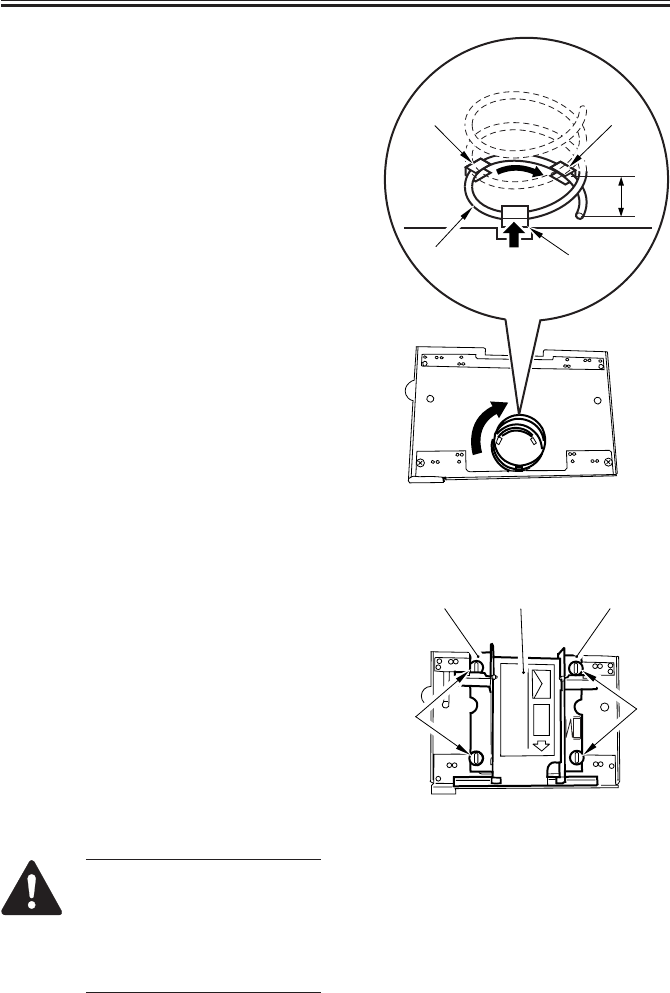
COPYRIGHT
©
2001 CANON INC. 2000 2000 2000 2000 CANON iR2200/iR2800/iR3300 REV.0 MAR. 2001
CHAPTER 11 ENVELOPE FEEDER ATTACHMENT-B1
11-8 P
3) Thread the edge of the spring [1] that
comes as an attachment so as to fit it
through the catch 1 [2] and then the
catch 2 [3].
4) Holding the bottom (1st and 2nd loops)
of the spring, fit it through the catch 3
[4]; then, thread it until distance A is
about 15 mm from the catch 2 [3].
At this time, check to make sure that the
spring is firmly on the bottom plate.
F11-502-03
5.3 Changing the Size
5.3.1 Changing the Size
1) Match the lifter [1] and the side guide
plate [2] against the size positioning
line of the envelope feeder in relation to
the edges of the side guide plate; then,
secure them in place by using two
mounting screws [3] each.
F11-503-01
Take care so that the side guide
plate will not extend beyond the
envelope feeder (as by choosing
the wrong mounting hole). See
the next page for the correct
mounting hole.
A
[2]
[1]
[3]
[4]
[3] [3]
[2] [1] [2]
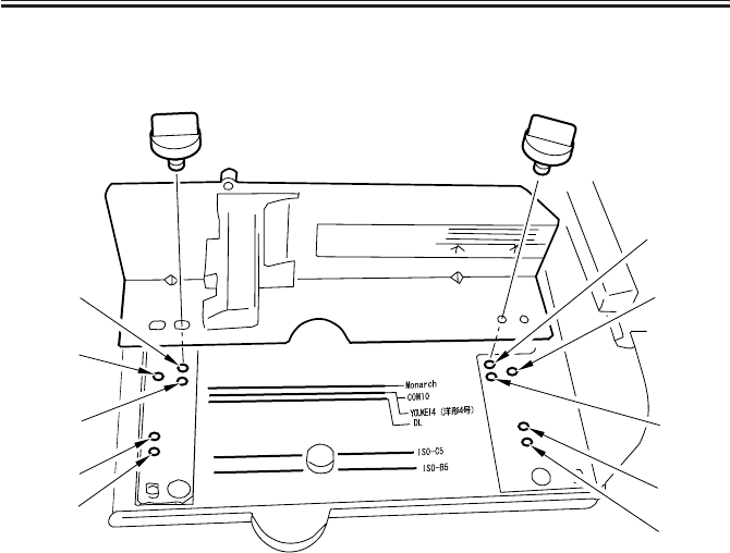
COPYRIGHT
©
2001 CANON INC. 2000 2000 2000 2000 CANON iR2200/iR2800/iR3300 REV.0 MAR. 2001
CHAPTER 11 ENVELOPE FEEDER ATTACHMENT-B1
11-9 P
Mounting Hole by Side Guide Plate (front)
(The side guide rear is symmetrically opposite.)
F11-503-02
2) Register the specifications of the enve-
lope using ‘register envelope’ offered as
part of common settings.
3) Check to make sure that envelopes are
fed correctly.
[3]
[4]
[5]
[2]
[1]
[3]
[4]
[5]
[2]
[1]
[1] Monarch
[2] COM10, YOUKEI 4
[3] DL
[4] ISO-C5
[5] ISO-B5

COPYRIGHT
©
2001 CANON INC. 2000 2000 2000 2000 CANON iR2200/iR2800/iR3300 REV.0 MAR. 2001
TROUBLESHOOTING

COPYRIGHT
©
2001 CANON INC. 2000 2000 2000 2000 CANON iR2200/iR2800/iR3300 REV.0 MAR. 2001
CONTENTS
T1
Contents
CHAPTER 1 MAINTENANCE AND INSPECTION
CHAPTER 2
IMAGE ADJUSTMENT BASIC PROCEDURE
1 Periodically Replaced Parts........... 1-1T
1.1 Reader Unit ............................. 1-1T
1.2 Printer Unit ............................. 1-1T
1.3 Side Paper Deck ...................... 1-1T
1.4 Cassette Feeding unit .............. 1-1T
1.5 Inner 2-Way Tray .................... 1-1T
2 Consumables and Durables ........... 1-2T
2.1 Checking the Time of Replacement
................................................ 1-2T
2.2 Reader Unit ............................. 1-2T
2.3 Printer Unit ............................. 1-2T
2.4 Side Paper Deck ...................... 1-3T
2.5 Cassette Feeding Unit ............. 1-3T
2.6 Inner 2-Way Tray-A1 .............. 1-3T
3 Periodical Servicing Procedure ..... 1-4T
4 Scheduled Servicing Chart ............ 1-6T
4.1 Reader Unit ............................. 1-6T
4.2 Printer Unit ............................. 1-7T
5 Points to Note for Scheduled Servicing
....................................................... 1-8T
6 Cleaning the Bottom of the Developing
Assembly ....................................... 1-9T
6.1 Cleaning the Bottom of the Devel-
oping Assembly ...................... 1-9T
1 Making lnitial Checks ................... 2-1T
2 Checking the Scanner Side ........... 2-1T
3 Checking the Printer Side (1/3)..... 2-2T
4 Checking the Printer Side (2/3)..... 2-2T
5 Checking the Printer Side (3/3)..... 2-2T
CHAPTER 3 STANDARDS AND ADJUSTMENTS
1 Image Adjustments ........................ 3-1T
1.1 Standards of Image Position ... 3-1T
1.2 Checking the Image Position .. 3-2T
1.3 Adjusting Left/Right lamge Margin
................................................ 3-3T
1.3.1 Adjusting the Registration for
the Cassette Rear Front ..... 3-3T
1.3.2 Adjusting the Registration for
the Multifeeder Rear Front
.......................................... 3-4T
1.3.3 Adjusting the Registration for
the Deck ............................ 3-4T
1.3.4 Duplex Feeding Unit ........ 3-5T
1.4 Adjusting the Image Leading Edge
Margin ..................................... 3-5T
1.5 Adjusting the Left/Right Non-Im-
age Width ................................ 3-5T
1.6 Adjusting the Leading Edge Non-
Image Width ............................ 3-6T
2 Scanning System ........................... 3-6T
2.1 After Replacing the Scanning Lamp
................................................ 3-6T
2.2 Mounting the Motor Unit ....... 3-7T
2.3 Routing the Scanner Drive Cable
................................................ 3-8T
2.4 Adjusting the Position of the No. 1/
No. 2 Mirror Base ................... 3-9T
2.5 Mounting the Copyboard Glass
.............................................. 3-11T
2.6 Mounting the Reader Upper Frame
.............................................. 3-12T

COPYRIGHT
©
2001 CANON INC. 2000 2000 2000 2000 CANON iR2200/iR2800/iR3300 REV.0 MAR. 2001
CONTENTS
T2
CHAPTER 4 TROUBLESHOOTING IMAGE FAULTS/
MALFUNCTIONS
1 Making Initial Checks ................... 4-1T
1.1 Checking the Site of Installation
................................................ 4-1T
1.2 Checking the Originals ........... 4-1T
1.3 Checking the ADF Platen,
Copyboard cover, and Copyboard
glass (standard white plate) .... 4-1T
1.4 Charging Roller and Static Elimina-
tor ............................................ 4-2T
1.5 Checking the Developing Assembly
................................................ 4-2T
1.6 Checking the Paper ................. 4-2T
1.7 Checking the Periodically Replaced
Parts......................................... 4-2T
1.8 Image Adjustment Basic Procedure
................................................ 4-2T
1.9 Others ...................................... 4-3T
2 Samples of Image Faults ............... 4-6T
3 Troubleshooting Image Faults....... 4-7T
3.1 The copy is too light (halftone area
only) ........................................ 4-7T
3.2 The copy is too light (including
solid black).............................. 4-8T
3.3 The copy is too light (entire face,
considerable) ......................... 4-10T
3.4 The copy has uneven density
(darker at front) ..................... 4-12T
3.5 The copy has uneven density
(lighter at front)..................... 4-12T
2.7 Points to Note When Replacing the
CCD Unit .............................. 3-12T
2.8 When Replacing the Reader Con-
troller PCB ............................ 3-12T
3 Image Formation System ............ 3-13T
3.1 Positioning the Developing Assem-
bly Magnetic Seal ................. 3-13T
3.2 Mounting the Developing Assembly
Blade ..................................... 3-13T
3.3 Removing the Paper Lint ...... 3-14T
3.4 Cleaning the Waste Toner Case
.............................................. 3-15T
4 Fixing System ............................. 3-16T
4.1 Mounting the Locking Cam Unit
.............................................. 3-16T
5 Paper Deck .................................. 3-17T
5.1 Mounting the Front Cover .... 3-17T
5.2 Adjusting the Paper Level Indicator
.............................................. 3-18T
5.3 Adjusting the Position of the Sup-
port Member ......................... 3-18T
5.4 Mounting the Deck Pickup Roller
.............................................. 3-19T
5.5 Removing the Deck Pickup/Feeding
Roller .................................... 3-19T
5.6 Orientation of the Deck Pickup/
Feeding Roller ...................... 3-20T
5.7 Adjusting the Deck Separation
Roller Pressure ...................... 3-20T
5.8 Position of the Deck Pickup Roller
Releasing Solenoid (SL1D) .. 3-21T
5.9 Adjusting the Height of the Side
Member ................................. 3-22T
5.9.1 Before Making Adjustments
........................................ 3-22T
5.9.2 Making Adjustments....... 3-22T
6 Cassette Feeding Unit-W1 .......... 3-23T
6.1 Mounting the Pedestal Main Motor
.............................................. 3-23T
7 Envelope Feeder Attachment ....... 3-24T
7.1 Envelopes and Type of Spring
.............................................. 3-24T
7.2 Replacing the Spring............. 3-24T
7.2.1 Replacing the Spring ...... 3-24T
7.3 Changing the Size ................. 3-25T
7.3.1 Changing the Size ........... 3-25T

COPYRIGHT
©
2001 CANON INC. 2000 2000 2000 2000 CANON iR2200/iR2800/iR3300 REV.0 MAR. 2001
CONTENTS
T3
3.6 The copy is foggy (entire face)
.............................................. 4-13T
3.7 The copy is foggy (vertical) .. 4-14T
3.8 The copy has a black line (vertical,
fuzzy, thick) .......................... 4-14T
3.9 The copy has a black line (vertical,
fine) ....................................... 4-15T
3.10 The copy has a white spot (vertical)
.............................................. 4-16T
3.11 The copy has a white line (vertical)
.............................................. 4-16T
3.12 The copy has a white spot (horizon-
tal) ......................................... 4-17T
3.13 The back of the copy is soiled/
Soiled edge............................ 4-18T
3.14 The copy has a fixing fault ... 4-19T
3.15 The copy has a displaced leading
edge ....................................... 4-20T
3.16 The copy has a displaced leading
edge (large margin) ............... 4-20T
3.17 The copy has a displaced margin
(no margin) ........................... 4-20T
3.18 The copy is blurred ............... 4-21T
3.19 The copy is foggy (horizontal)
.............................................. 4-22T
3.20 The copy has inadequate sharpness
.............................................. 4-23T
3.21 The copy is completely blank
.............................................. 4-24T
3.22 The copy is completely black
.............................................. 4-26T
3.23 The copy has a block/white dot af-
ter replacement of the drum unit
.............................................. 4-27T
3.24 The copy has a black line (stream
reading) ................................. 4-27T
4 Troubleshooting Malfunctions .... 4-28T
4.1 Power Supply System ........... 4-28T
4.1.1 The AC power is absent .. 4-28T
4.1.2 The DC power is absent
........................................ 4-29T
4.2 Printer Unit ........................... 4-30T
4.2.1 Pickup fails ..................... 4-30T
4.2.2 The lifter fails to move up
(pickup from the cassette)
........................................ 4-31T
4.2.3 The vertical path roller fails to
rotate ............................... 4-32T
4.2.4 The registration roller fails to
rotate ............................... 4-32T
4.2.5 Pickup from the multifeeder
tray fails (i.e., the pickup roller
fails to rotate) .................. 4-33T
4.2.6 Pickup from the multifeeder
tray fails (i.e., the multifeeder
holding plate fails to move up)
........................................ 4-33T
4.2.7 The photosensitive drum fails to
rotate ............................... 4-34T
4.2.8 The pre-exposure lamp fails to
go ON ............................. 4-34T
4.3 Reader Unit ........................... 4-35T
4.3.1 The No. 1 mirror base fails to
move ............................... 4-35T
4.3.2 The scanning lamp fails to go
ON .................................. 4-36T
4.4 Message Indication ............... 4-37T
4.4.1 The “Add Toner” message fails
to go OFF........................ 4-37T
4.4.2 The “Control Card Set” mes-
sage fails to go OFF (when no
card reader is installed) ... 4-37T
4.4.3 The “Add Paper” message fails
to go OFF........................ 4-37T
4.4.4 The “Close the Front Cover”
massage fails to go OFF .. 4-38T
4.5 Paper Deck ............................ 4-39T
4.5.1 Pickup fails ..................... 4-39T
4.5.2 The deck lifter fails to move up
........................................ 4-40T
5 Troubleshooting Feeding Faults ... 4-41T
5.1 Paper Jams ............................ 4-41T
5.1.1 Pickup Assembly ............ 4-42T
5.1.2 Separation/Feeding Assembly
........................................ 4-43T
5.1.3 Fixing/Delivery Assembly, Du-
plex Reversing Assembly
........................................ 4-43T

COPYRIGHT
©
2001 CANON INC. 2000 2000 2000 2000 CANON iR2200/iR2800/iR3300 REV.0 MAR. 2001
CONTENTS
T4
1 Outline of Service Mode ............... 5-1T
1.1 Outline .................................... 5-1T
1.2 Starting Service Mode and Making
Selections ................................ 5-2T
1.3 Ending Service Mode ............. 5-3T
1.4 Backing Up Service Mode ...... 5-3T
1.5 Using Service Mode ............... 5-4T
1.5.1 Initial Screen ..................... 5-4T
1.5.2 Level 1/Level 2 Item Screen
.......................................... 5-4T
1.5.3 Level 3 Item Screen .......... 5-5T
2 DISPLAY Control Display Mode .. 5-6T
2.1 COPIER .................................. 5-6T
2.2 FEEDER ............................... 5-19T
3 I/O, I/O Display mode ................. 5-20T
3.1 DC-CON ............................... 5-21T
3.2 R-CON .................................. 5-28T
3.3 MN-CON .............................. 5-31T
3.4 FEEDER ............................... 5-33T
3.5 SORTER ............................... 5-35T
3.5.1 Finisher-J1 ...................... 5-35T
3.5.2 Saddle Finisher-G1 ......... 5-38T
3.5.3 Puncher Unit (Saddle Finisher-
G1) .................................. 5-41T
4 ADJUST Adjustment Mode ........ 5-44T
4.1 COPIER ................................ 5-44T
4.2 FEEDER ............................... 5-58T
4.3 SORTER ............................... 5-59T
5 FUNCTION Operation/Inspection
Mode ........................................... 5-61T
CHAPTER 5 SURVICE MODE
5.1.4 Duplex Feeding Assembly
........................................ 4-44T
5.2 Faulty Feeding ...................... 4-45T
5.2.1 Double Feeding .............. 4-45T
5.2.2 Wrinkles ......................... 4-45T
6 Outline of Electrical Components
..................................................... 4-46T
6.1 Introduction ........................... 4-46T
6.1.1 Guide to the List ............. 4-46T
6.1.2 Checking the Photointerrupters
........................................ 4-47T
6.2 E201 (reader unit/printer unit)4-48T
6.2.1 Clutches .......................... 4-48T
6.2.2 Solenoids, Switches ........ 4-48T
6.2.3 Motors (1/2) .................... 4-50T
6.2.3 Motors (2/2) .................... 4-52T
6.2.4 Fans ................................. 4-54T
6.2.5 Sensors (1/3) ................... 4-56T
6.2.5 Sensors (2/3) ................... 4-58T
6.2.5 Sensors (3/3) ................... 4-60T
6.2.6 Lamps, Heaters, and Others
........................................ 4-62T
6.2.7 PCBs ............................... 4-64T
6.3 Side Paper Deck-L1 .............. 4-66T
6.3.1 Clutches .......................... 4-66T
6.3.2 Solenoids, and Switches .. 4-66T
6.3.3 Motors............................. 4-66T
6.3.4 Sensors ............................ 4-68T
6.3.5 PCBs ............................... 4-68T
6.4 2-Cassette Feeding Unit-W1
.............................................. 4-70T
6.4.1 Clutches .......................... 4-70T
6.4.2 Solenoids and Switches .. 4-70T
6.4.3 Motors............................. 4-70T
6.4.4 Sensors ............................ 4-72T
6.4.5 PCBs ............................... 4-72T
6.5 Inner 2-Way Tray-A1 ............ 4-74T
6.5.1 Clutches .......................... 4-74T
6.5.2 Solenoids and Switches .. 4-74T
6.6 Super G3 FAX Board-J1 ....... 4-76T
6.6.1 Others ............................. 4-76T
6.6.2 PCBs ............................... 4-76T
6.7 Variable Resistors (VR), Light-
Emitting Diodes, and Check Pins by
PCB ....................................... 4-78T
6.7.1 Main Controller PCB...... 4-79T
6.7.2 DC Controller PCB ........ 4-80T
6.7.3 Reader Controller PCB ... 4-80T
6.7.4 Composite Power Supply PCB
........................................ 4-81T
6.7.5 Fixing Film Sensor PCB
........................................ 4-81T

COPYRIGHT
©
2001 CANON INC. 2000 2000 2000 2000 CANON iR2200/iR2800/iR3300 REV.0 MAR. 2001
CONTENTS
T5
1 Self Diagnosis ............................... 6-1T
1.1 Detail Codes (copier) .............. 6-3T
1.2 ADF Error Codes .................. 6-37T
1.3 Saddle Finisher-G1 Error Codes
.............................................. 6-38T
1.3.1 Error Code of the Finisher Unit
.............................................. 6-38T
1.4 Finisher-J1 Error Codes ........ 6-43T
CHAPTER 6 SELF DIAGNOSIS
5.1 COPIER ................................ 5-61T
6 OPTION Machine Settings Mode
..................................................... 5-82T
6.1 COPIER ................................ 5-82T
6.2 FEEDER ............................... 5-95T
6.3 SORTER ............................... 5-95T
6.4 BOARD ................................. 5-96T
7 TEST Test Print Mode ................ 5-97T
8 COUNTER Counter Mode........ 5-101T
CHAPTER 7 UPGRADING
1 Upgrading...................................... 7-1T
1.1 Outline .................................... 7-1T
1.1.1 Download Mode ............... 7-1T
1.1.2 Making Pre-Checks .......... 7-2T
1.2 Data Control ............................ 7-5T
1.3 Downloading the System Software,
RUI, and Language Module.... 7-8T
1.3.1 Making Connections......... 7-8T
1.3.2 Downloading .................... 7-8T
1.3.3 After Downloading ......... 7-14T
1.4 Upgrading the BOOT ROM ... 7-14T
1.4.1 Making Preparations....... 7-14T
1.4.2 Connection...................... 7-15T
1.4.3 Preparing BOOT ROM ... 7-15T
1.4.4 After Downloading ......... 7-19T
1.5 Formatting the HDD ............. 7-20T
1.5.1 Making Connections....... 7-20T
1.5.2 Starting Formatting ......... 7-20T
1.5.3 Points to Note When Formatting
the Hard Disk.................. 7-26T
1.6 Downloader PCB .................. 7-27T
1.6.1 Purpose ........................... 7-27T
1.6.2 Downloader PCB Components
........................................ 7-27T
1.6.3 Download Procedure ...... 7-28T
1.6.4 Disconnecting ................. 7-32T
1.7 Upgrading by Replacing the
DIMM/ROM ......................... 7-33T
2 Backing Up Data ......................... 7-34T
2.1 Outline .................................. 7-34T
2.2 Backing Up Data................... 7-35T
2.2.1 Making Preparations....... 7-35T
2.2.2 Making Connections....... 7-35T
2.2.3 Backing Up Data ............ 7-36T
2.2.4 Downloading Backup Data
........................................ 7-41T
2.2.5 Managing Backup Data .. 7-45T
A. General Timing Chart...................... A-1
B. General Circuit Diagram ................. A-3
C. Side Paper Deck-L1 General Circuit
Diagram ........................................... A-5
D. 2-Cassette Feeding Unit-W1 General
Circuit Diagram ............................... A-6
E. Inner 2-Way Tray-A1 General Circuit
Diagram ........................................... A-7
F. List of Special Tools ........................ A-8
G. List of Solvents/Oils...................... A-10
APPENDIX

COPYRIGHT
©
2001 CANON INC. 2000 2000 2000 2000 CANON iR2200/iR2800/iR3300 REV.0 MAR. 2001
CHAPTER 1
MAINTENANCE AND INSPECTION

COPYRIGHT
©
2001 CANON INC. 2000 2000 2000 2000 CANON iR2200/iR2800/iR3300 REV.0 MAR. 2001
CHAPTER 1 MAINTENANCE AND INSPECTION
1-1 T
1 Periodically Replaced Parts
Some of the parts used in the machine must be replaced on a periodical basis to ensure a
specific level of product performance; be sure to replace them as indicated, as they will af-
fect the machine functions appreciably once they fail.
If possible, plan the replacement to coincide with a scheduled visit to the user’s.
The estimates are subject to change depending on the conditions of the site
of installation or how the machine is used.
1.1 Reader Unit
The reader unit does not have parts that require periodical replacement.
1.2 Printer Unit
The printer unit does not have parts that require periodical replacement.
1.3 Side Paper Deck
The side paper deck does not have parts that require periodical replacement.
1.4 Cassette Feeding unit
The cassette feeding unit does not have parts that require periodical replacement.
1.5 Inner 2-Way Tray
The inner 2-way tray does not have parts that require periodical replacement.

COPYRIGHT
©
2001 CANON INC. 2000 2000 2000 2000 CANON iR2200/iR2800/iR3300 REV.0 MAR. 2001
CHAPTER 1 MAINTENANCE AND INSPECTION
1-2 T
2 Consumables and Durables
Some parts of the machine may require replacement over the period of product warranty
because of wear or damage. Replace them as needed.
2.1 Checking the Time of Replacement
Use service mode to find out when to replace a specific part:
COPIER>COUNTER>DRBL-2.
2.2 Reader Unit
The reader unit does not have parts designated as a durable.
2.3 Printer Unit
As of March 2001
No. Part name Part No. Q’ty Life (prints) Remarks
1 Transfer roller FF6-0104 1 240,000
2 Transfer static eliminator FF5-7246 1 240,000
3 Developing cylinder FG6-5714 1 480,000
4 Fixing cleaning roller FG6-5709 1 150,000
5 Pre-exposure lamp FG5-6297 1 240,000
6 Pickup roller FF5-4552-020 2 120,000 Actual prints made
7 Feeding roller FF5-4552-020 2 120,000 Actual prints made
8 Separation roller FF5-4634-020 2 120,000 Actual prints made
9 Pickup roller FB1-8581 1 240,000 Actual prints made
(multifeeder)
10 Separation pad FE5-4132 1 240,000 Actual prints made
(multifeeder)
11 Fixing film unit (100V) FG6-5712 1 150,000
12 Fixing film unit (115V) FG6-6039 1 150,000
13 Fixing film unit (230V) FG6-6041 1 150,000
T01-203-01

COPYRIGHT
©
2001 CANON INC. 2000 2000 2000 2000 CANON iR2200/iR2800/iR3300 REV.0 MAR. 2001
CHAPTER 1 MAINTENANCE AND INSPECTION
1-3 T
2.4 Side Paper Deck
As of March 2001
No. Part name Part No. Q’ty Life (prints) Remarks
1 Pickup roller (front) FF5-7830 1 240,000 Actual prints made
2 Pickup roller (rear) FF5-7829 1 240,000 Actual prints made
3 Feeding roller FF5-7541 1 240,000 Actual prints made
4 Separation roller FB2-7777-020 1 240,000 Actual prints made
T01-203-03
2.5 Cassette Feeding Unit
As of March 2001
No. Part name Part No. Q’ty Life (prints) Remarks
1 Pickup roller FF5-4552-020 2 120,000 Actual prints
2 Feeding roller FF5-4552-020 2 120,000 Actual prints
3 Separation roller FF5-4634-020 2 120,000 Actual prints
2.6 Inner 2-Way Tray-A1
The inner 2-way tray-A1 does not have parts that are designated as a durable.

COPYRIGHT
©
2001 CANON INC. 2000 2000 2000 2000 CANON iR2200/iR2800/iR3300 REV.0 MAR. 2001
CHAPTER 1 MAINTENANCE AND INSPECTION
1-4 T
3 Periodical Servicing Procedure
1. As a rule, provide periodical servicing every 120,000 prints.
2. Before setting out on a scheduled visit, check the Service Book, and
take any parts that may require replacement.
As of June 2001
Work Procedure
1. Report to the person in charge, and check the general condition.
2. Record the counter reading, and check the faulty prints.
3. Make test prints, and check them for the following: (1) image density, (2) white back-
ground for soiling, (3) characters for clarity, (4) margin, (5) fixing, registration, and
back for soiling.
The margin must meet the following standards:
Leading edge: 2.5 ± 1.5 mm
Left edge: 2.5 ± 1.5 mm
Right edge: 0.5 mm or more
Trailing edge: 2.5 +1.1, -1.7 mm (smaller than B4) <2.5 ± 2.0 mm>
3.5 +0.6, -2.8 mm (B4 or larger) <3.5 ± 2.0 mm>
5.5 +1.5, -5.0 mm (free size)
< >: with DADF-H1
4. Optical Unit
Clean the following using a blower brush to clean; if the dirt is excessive, use alcohol:
(1) No. 1/2/3 mirror, (2) original illuminating reflecting plate, (3) lens, (4) original size
sensor.
5. Scanner Drive System
(1) Scanner cable; check the tension, and adjust as necessary. Inspect and adjust the scan-
ner cable only when the machine has made the first 250,000 prints.
(2) Scanner rail; clean the slide area, and apply silicone oil (FY9-6011).

COPYRIGHT
©
2001 CANON INC. 2000 2000 2000 2000 CANON iR2200/iR2800/iR3300 REV.0 MAR. 2001
CHAPTER 1 MAINTENANCE AND INSPECTION
1-5 T
6. Feeding System
Clean the following: (1) feeding assembly base, (2) fixing inlet guide (upper, lower), (3)
transfer guide, (4) pre-registration assembly (paper lint).
7. Image Formation System
Clean the following: developing member, (2) developing assembly bottom.
8. Optical Unit
Clean the following with a special tool: (1) bending mirror.
9. Image Formation System
Inspect and, as necessary, remove the waste toner and then clean the waste toner case;
or, replace the waste toner case if any:
1. Be sure to dispose of the water toner according to the standards im-
posed by the government concerned.
2. Do not dispose of waste toner into fire (to avoid explosion).
10. Make test copies.
11. Make sample copies.
12. Check the operation of the leakage breaker.
While the power switch is ON, press the test switch of the leakage breaker to make sure
that it operates normally (i.e., the lever goes OFF to cut the power).
If the leakage breaker fails to operate normally, replace it and make a check once again.
To reset,
After making a check, turn off the main power switch (the lever should go ON), and
then turn on the main power switch.
13. Put the sample copies into order, and clean up the area around the machine.
14. Fill out the Service Book, and report to the person in charge; put a description of the
check made on the operation of the leakage breaker in the Service Book.
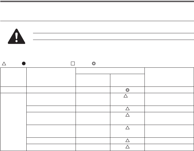
COPYRIGHT
©
2001 CANON INC. 2000 2000 2000 2000 CANON iR2200/iR2800/iR3300 REV.0 MAR. 2001
CHAPTER 1 MAINTENANCE AND INSPECTION
1-6 T
4 Scheduled Servicing Chart
Do not use solvents or oils not indicated herein.
4.1 Reader Unit
: Clean : Replace ×: Lubricate : Adjust : Inspect
T01-401-01
Part
Scanner cable
Scanner rail
Copyboard glass
No. 1 through No. 3
mirror
Original illumination
reflecting plate
Original size sensor
Lens
Unit
Scanner
Optical unit
Upon
installation
Maintenance intervals
Remarks
Silicone oil
(S20; FY9-6011)
every 120,000
×
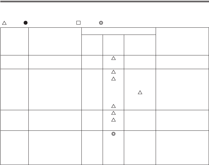
COPYRIGHT
©
2001 CANON INC. 2000 2000 2000 2000 CANON iR2200/iR2800/iR3300 REV.0 MAR. 2001
CHAPTER 1 MAINTENANCE AND INSPECTION
1-7 T
4.2 Printer Unit
: Clean : Replace ×: Lubricate : Adjust : Inspect
Part
Folding mirror
Feeding assembly base
Fixing inlet guide, up-
per/lower
Pre-registration (paper
lint)
Transfer guide
Developing member
Base (developing as-
sembly)
Waste toner case
Unit
Laser opti-
cal unit
Pickup/
feeding as-
sembly
Developing
assembly
Waste toner
collection
assembly
Upon in-
stallation
every
120,000
Maintenance intervals
Remarks
Use special tool.
Inspect/remove.
(Remove waste toner,
and then clean the toner
case. Replase the toner
case, if any.)
Upon replace-
ment of drum
cartridge
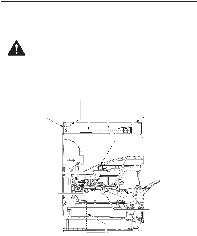
COPYRIGHT
©
2001 CANON INC. 2000 2000 2000 2000 CANON iR2200/iR2800/iR3300 REV.0 MAR. 2001
CHAPTER 1 MAINTENANCE AND INSPECTION
1-8 T
5 Points to Note for Scheduled Servicing
Unless otherwise indicated, use lint-free paper and alcohol.
• If you used solvent, check to make sure that the solvent has dried be-
fore mounting the component back into the machine.
• Unless otherwise specified, do not use a moist cloth for cleaning.
• Provide scheduled servicing at the specified intervals.
F01-500-01
No. 1 through No. 3 mirrors
Cleaning (blower brush)
Reflecting shade
Cleaning (blower brush) Copyboard glass
Cleaning
Original size sensor
Cleaning (blower brush)
Scanner rail
Lubricating
Scanner cable
Check
Lens
Cleaning (blower brush)
Bending mirror
Cleaning (special tool)
Feeding assembly base
Cleaning
Developing assembly base
Dry wiping
Transfer guide
Cleaning
Developing assembly bottom
Cleaning
Waste toner case
Checking, disposing
(Remove waste toner, and then clean the
toner case, Replace the toner case, if any.)
Inlet guide (upper/lower)
Cleaning (solvent) Pre-registration guide
Cleaning (paper lint)
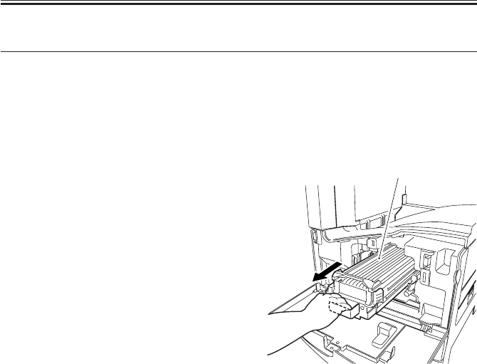
COPYRIGHT
©
2001 CANON INC. 2000 2000 2000 2000 CANON iR2200/iR2800/iR3300 REV.0 MAR. 2001
CHAPTER 1 MAINTENANCE AND INSPECTION
1-9 T
6 Cleaning the Bottom of the Developing Assembly
If the bottom of the developing assembly is not cleaned thoroughly, the residual toner can
soil the back and the leading edge or left/right edges of prints. If soiling is noted, clean also
the transfer guide and the static eliminator at the same time as the bottom of the developing
assembly.
6.1 Cleaning the Bottom of the Developing Assembly
1) Open the front door.
2) Slide out the developing assembly [1].
3) Dry wipe the bottom of the developing
assembly.
4) Slide in the developing assembly.
5) Close the front door.
F01-601-01
[1]

COPYRIGHT
©
2001 CANON INC. 2000 2000 2000 2000 CANON iR2200/iR2800/iR3300 REV.0 MAR. 2001
CHAPTER 2
IMAGE ADJUSTMENT BASIC PROCEDURE
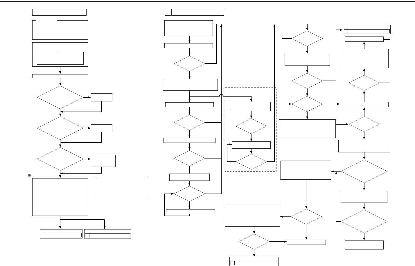
COPYRIGHT
©
2001 CANON INC. 2000 2000 2000 2000 CANON iR2200/iR2800/iR3300 REV.0 MAR. 2001
2-1 T
CHAPTER 2 IMAGE ADJUSTMENT BASIC PROCEDURE
Execute the following in service mode:
COPIER>FUNCTION>CCD>CCD-ADJ.
Check/clean the following:
[1] Mirrors [2] Lens
[3]
Standard white plate
[4]
Copyboard glass
[5] Scanning lamp [6]
Reflecting plate
Make a copy in text mode.
YES
Is there a
vertical line in the
image?
YES
YES
YES
NO
NO
NO
Make a copy in text mode.
Change the shading position. (Note 1)
Change the shading position.
Clean the copyboard glass.
(white plate position)
Is there a
vertical line in
the image?
Is there a
vertical line in
the image?
Is there a
vertical line in
the image?
YES
YES
YES
YES
NO
NO
NO
NO
Is the copy
image density
normal?
Execute the following in service mode:
COPIER>FUNCTION>DENS.
1. WHITE-ME
2. PD-DENS
3. PD-ME
Is the setting of the
following in service mode
485 µA or higher:
DISPLAY>HV-STS>
PRIMARY?
Is the setting of
the following in service mode
485 µA or higher:
DISPLAY>HV-STS>
PRIMARY?
Replace the drum unit;
then, execute the following in
service mode: COPIER>
FUNCTION>DPC>D-GAMMA.
Is the copy
image density in text
mode normal?
Reference:
Varying the setting of DENS-ADJ
affects the density of all following
copying modes:
• Auto
• Text
• Text/photo
• Photo (print photo/film photo)
Vary the setting in service mode:
COPIER>ADJUST>DENS>DENS-ADJ.
•
If the image is dark, decrease the setting.
•
If the image is light, increase the setting.
3 Checking the Printer Side (1/3).
5 Checking the Printer Side (3/3).
Replace the composite
power supply PCB.
End.
Set '5' to the following in service mode:
COPIER>ADJUST>DENS>DENS-ADJ.
NO
NO
NO
NO
NO
YES
YES
Execute shading in service mode:
FUNCTION>CCD>CCD-ADJ.
Vary the setting in service mode:
COPIER>ADJUST>AE-AE-TBL.
• If the image is dark, decrease
the setting.
• If the image is light, increase
the setting.
End.
Make a copy in AE mode.
YES
YES
YES
Is the white
background of the
copy foggy?
Is the copy
density normal?
Vary the setting in service mode:
COPIER>ADJUST>DENS>DENS-ADJ.
• If the image is dark, decrease the setting.
• If the image is light, increase the setting.
Is the copy
image density
normal?
Is the density
of the copy image
normal?
Is the image foggy?
NO
NO
NO
Is there a
vertical line in
the image?
YES
Make a copy in text mode.
Is there a
vertical line in
the image?
YES
If a line occurs only
when the ADF is used,
Clean the original reading
face of the ADF.
Note 1: In units of 8s, increase or decrease
the setting of FUNCTION>CCD
>SHDG-POS. Then, execute
FUNCTION>CCD>SH-PS-ST to see
that 'OK!' is indicated.
Output Condition
F value=5
If the copy image has a fault, If the test print has a fault,
1. Use paper fresh out of package.
(Moist paper will not allow correct
evaluation of images.)
2. Use paper with the highest degree of
"whiteness," of all available papers.
3. Use A3 paper (11x17), if possible.
Requirements:
Execute 'roller clean' in user mode
('adjust/clean').
The following will be cleaned:
[1]Primary charging roller
[2]Transfer charging roller
Reference:
Using the NA3 Test Chart, make 2 copies
in the following:
[1] Text mode
Reference: At optimum density, the copy
image should barely show
gray scale No. 0.
Generate 2 test prints each of the following in
COPIER>TEST>PG:
[1] TYPE4 (blank)
[2] TYPE5 (halftone)
[3] TYPE6 (solid black)
Clean the separation static eliminator.
Does the five
items on the right in
service mode match the settings
indicated on the
service label?
Enter the settings
indicated on the
service label.
Set it to '5'.
Set it to the
middle setting.
Is the setting of
'exposure recalibration'
under 'adjust/clean' in user
mode the middle
setting?
Is '5' indicated for
ADJUST>DENS>DENS-ADJ
in user mode?
2 Checking the Scanner Side. 3 Checking the Printer Side (1/3).
NO
NO
YES
NO
YES
YES
In service mode COPIER>ADJUST,
1. AE>AE-TBL
2. DEVELOP>DE-DC
3. DEVELOP>DE-OFST
4. HV-PRI>P-DC
5. HV-PRI>OFST1-DC
1
Making Initial Checks
2Checking the Scanner Side
Go to Go to
Go to
Go to
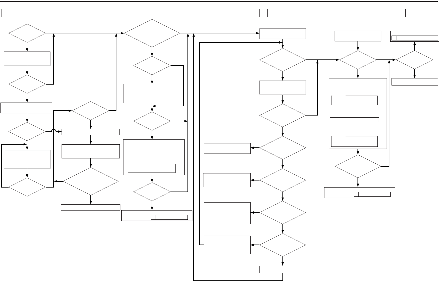
COPYRIGHT
©
2001 CANON INC. 2000 2000 2000 2000 CANON iR2200/iR2800/iR3300 REV.0 MAR. 2001
2-2 T
CHAPTER 2 IMAGE ADJUSTMENT BASIC PROCEDURE
YES
NO
NO
NO
NO
NO
NO
NO
NO
NO
NO
Is there a
vertical line in
the image?
YES
YES
YES
YES
YES
YES
YES
YES
YES
Is there a
vertical line in
the image?
Is there ea
vertical line in the
image?
Is the setting of the
following in service mode 485 µA:
DISPLAY>HV-STS>
PRIMARY?
Replace the composite power supply PCB.
Is there a
vertical line on the
surface of the
sleeve?
NO
NO
YES
NO
NO
NO NO
NO
NO
YES YES
YES
YES
Is there a
line on the surface
of the sleeve?
Clean the following:
[1] Laser mirror
[2] No. 1 mirror
Generate 10 test prints of the
following in service mode:
COPIER>TEST>PG.
TYPE6 (solid black)
Check the surface of the
developing sleeve by the naked eye.
Replace the drum unit.
Execute the following service mode:
COPIER>FUNCTION>DPC>D-GAMMA.
(initialization)
Is the image of TYPE6
(solid black) on test prints correct in
density and free
of fuzziness?
Is the image fuzzy?
Is the image
density appropriate?
Is the image
density appropriate?
Check the following,
and correct any fault:
[1] Feeding assembly for locking
[2] Transfer charging roller electrode
Adjust the setting of the following in
service mode:
COPIER>ADJUST>DEVELOP>DE-DC.
• If the image is light, decrease the setting.
• If the image is dark, increase the setting.
Caution:
Be sure to vary the setting in
equal amounts.
Check the image density by
generating test prints (TYPE5).
Is there an
appreciable difference
in density between left
and right of the
image?
YES
Clean the following:
[1] Laser mirror:
[2] No. 1 mirror
Are both rear and
front of the pre-exposure
lamp ON?
Is there a difference
in density between left and
right of the image?
YES
YES
NO
YES
Is the developing
assembly securely locked
in place?
Is the coating of toner
on the developing
sleeve uneven?
Replace the pre-exposure
lamp unit.
Lock it securely. If the locking
mechanism has a fault, replace it.
Generate 10 test prints (TYPE6);
then, if the coating of toner on
the developing sleeve is uneven,
replace the developing assembly.
Is the
feeding assembly
(transfer charging roller) locked
securely in place?
Lock the feeding assembly
(transfer charging roller)
securely; if the locking
mechanism is faulty, replace the
transfer charging roller unit.
Replace the laser scanner unit.
Check the image density by
generating test prints (TYPE4).
Are the printouts
foggy?
Is the image density
of the tense prints (TYPE6)
appropriate?
Is there a fault in
the copy image?
2 Checking the Scanner Side.
End.
1 Making Initial Checks.
Increase the setting of the following in
service mode:
COPIER>ADJUST>DEVELOP>DE-DC.
Caution:
Be sure to vary the setting in
equal amounts.
However, if the setting has already been
changed under
3 Checking the Printer Side (1/3),
decrease the following in service mode:
COPIER>ADJUST>HV-PRI>P-DC.
Caution:
Be sure to vary the setting in
equal amounts.
3Checking the Printer Side (1/3) 4Checking the Printer Side (2/3) 5Checking the Printer Side (3/3)
1 Making Initial Checks.
Replace the developing assembly, and make image
adjustments under
Replace the developing assembly, and make image
adjustments under
Go to

COPYRIGHT
©
2001 CANON INC. 2000 2000 2000 2000 CANON iR2200/iR2800/iR3300 REV.0 MAR. 2001
CHAPTER 3
STANDARDS AND ADJUSTMENTS
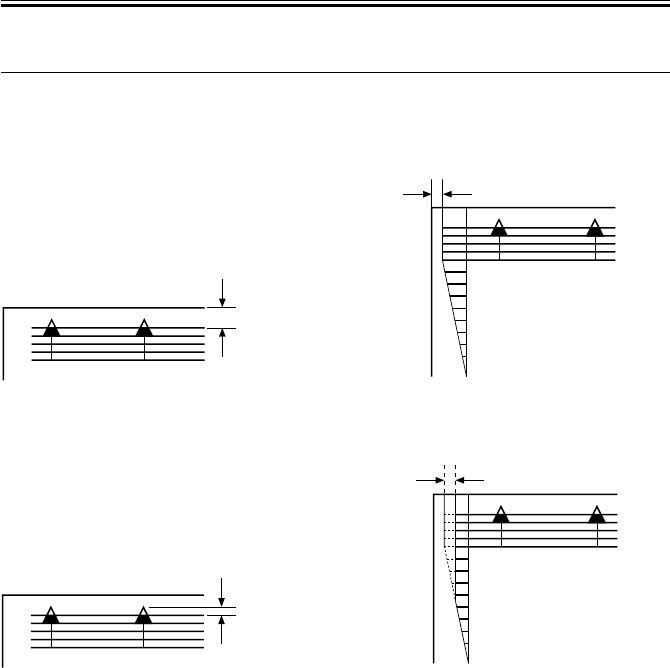
COPYRIGHT
©
2001 CANON INC. 2000 2000 2000 2000 CANON iR2200/iR2800/iR3300 REV.0 MAR. 2001
CHAPTER 3 STANDARDS AND ADJUSTMENTS
3-1 T
1 Image Adjustments
1.1 Standards of Image Position
The image margin/non-image width of a print made in Direct must be as follows:
F03-101-01 Image Leading Edge Margin F03-101-02 Left/Right Image Margin
F03-101-04 Left Non-Image Width
< >: with DADF-H1
F03-101-03 Leading Edge Non-Image
Width
2.5±1.5mm
0
2
4
6
8
10
2.5±1.5mm
2.5±1.5mm<2.5±2.0mm>
0
2
4
6
8
10
2.5±1.5mm

COPYRIGHT
©
2001 CANON INC. 2000 2000 2000 2000 CANON iR2200/iR2800/iR3300 REV.0 MAR. 2001
CHAPTER 3 STANDARDS AND ADJUSTMENTS
3-2 T
1.2 Checking the Image Position
Make prints using the following as the source of paper (10 prints each), and check to see
that the image margin and the non-image width are as indicated:
• Each cassette
• Manual feed tray
• Duplex feeding unit
• Side paper deck
If not as indicated, adjust the image position in the following order:
1. Adjusting the left/right image margin (registration)
2. Adjusting the image leading edge margin (registration)
3. Adjusting the left/right non-image width (CCD read start position)
4. Leading edge non-image width (scanner image leading edge position)
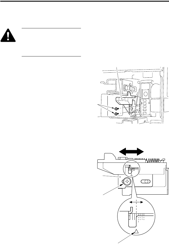
COPYRIGHT
©
2001 CANON INC. 2000 2000 2000 2000 CANON iR2200/iR2800/iR3300 REV.0 MAR. 2001
CHAPTER 3 STANDARDS AND ADJUSTMENTS
3-3 T
1.3 Adjusting Left/Right lamge Margin
1.3.1 Adjusting the Registration for the Cassette Rear Front
Try the following service mode
first; if not corrected, perform
the adjustments that follow:
FUNCTION>CI-ADJ-Y/C2-
ADJ-Y/C3-ADJ-Y/C4-ADJ-Y
1) Remove the cassette.
2) Remove the two screws [1], and detach
the horizontal registration base assem-
bly [2].
F03-103-01
3) Loosen the screw [1], and adjust the
horizontal registration plate [2].
When making adjustments, try to match
the arrow [3] against the index (each
graduation being about 1 mm).
F03-103-02
[1]
[2]
[2]
[1]
[3]
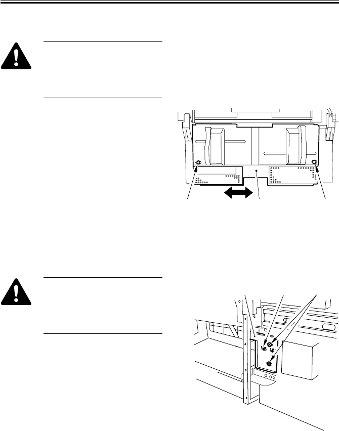
COPYRIGHT
©
2001 CANON INC. 2000 2000 2000 2000 CANON iR2200/iR2800/iR3300 REV.0 MAR. 2001
CHAPTER 3 STANDARDS AND ADJUSTMENTS
3-4 T
1.3.2 Adjusting the Registration for the Multifeeder Rear Front
Try the following service mode
first; if not corrected, perform
the adjustments that follow:
COPIER>FUNCTION>MF-
ADJ
1) Open the multifeeder tray.
2) Loosen the two screws [1], and move
the side guide plate unit [2] back and
forth to adjust.
F03-103-03
1.3.3 Adjusting the Registration for the Deck
Try the following service mode
first; if not corrected, perform
the adjustments that follow:
COPIER>FUNCTION>DK-
ADJ-Y
1) Slide out the compartment.
2) Using the two screws [2], change the
position of the latch plate [1] of the
deck open solenoid (SL2D) found at the
left rear. (At this time, use the index [3]
on the latch plate as a reference.)
F03-103-04
3) Close the compartment, and check to
make sure that the gap of the front cover
is 3 ±1 mm.
4) If the gap is not 3 ±1 mm, adjust the
front cover.
[2] [1][1]
[1] [3] [2]
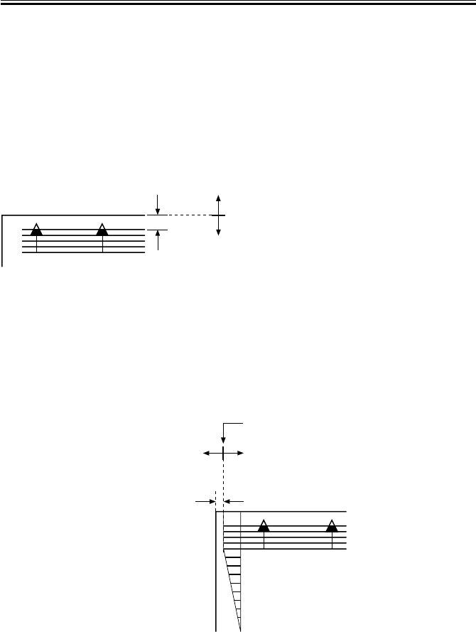
COPYRIGHT
©
2001 CANON INC. 2000 2000 2000 2000 CANON iR2200/iR2800/iR3300 REV.0 MAR. 2001
CHAPTER 3 STANDARDS AND ADJUSTMENTS
3-5 T
1.3.4 Duplex Feeding Unit
1) Adjust the image margin as indicated using service mode: COPIER>ADJUST>Feed-
ADJ>ADJ-REFE.
1.4 Adjusting the Image Leading Edge Margin
1) Adjust the image margin in service mode so that it is as indicated:
COPIER>ADJUST>Feed-ADJ>REGIST.
F03-104-01
1.5 Adjusting the Left/Right Non-Image Width
1) Adjust the non-image width in service mode so that it is as indicated:
COPIER>ADJUST>ADJ-XY>ADJ-Y.
F03-105-01
Edge of paper
Decreasing the REGIST setting
(A decrease by ‘10’ will increase the margin by 1 mm.)
Increasing the REGIST setting
(An increase by ‘10’ will decrease the margin by 1 mm.)
2.5mm±2.0
Edge of image
Increasing the ADJ-Y setting
(An increase by ‘12’ will increase
the non-image width by 1 mm.)
Decreasing the ADJ-Y setting
(A decrease by ‘12’ will
decrease the margin by 1 mm.)
0
2
4
6
8
10
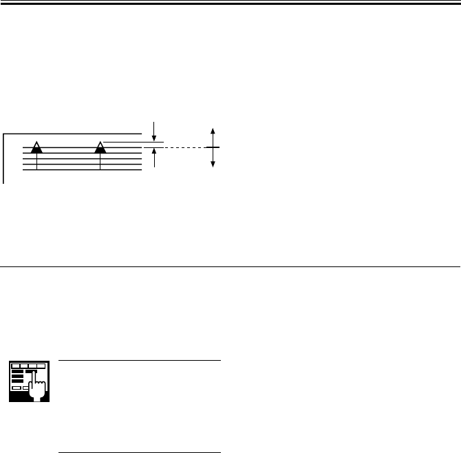
COPYRIGHT
©
2001 CANON INC. 2000 2000 2000 2000 CANON iR2200/iR2800/iR3300 REV.0 MAR. 2001
CHAPTER 3 STANDARDS AND ADJUSTMENTS
3-6 T
1.6 Adjusting the Leading Edge Non-Image Width
1) Adjust the non-image width in service mode so that it is as indicated:
COPIER>ADJUST>ADJ-XY>ADJ-X.
F03-106-01
2 Scanning System
2.1 After Replacing the Scanning Lamp
Execute ‘CCD auto adjust’ in service
mode, and record the updated CCD adjust-
ment data on the service label.
1. CCD Auto Adjust
COPIER>FUNCTION>CCD>
CCD-ADJ
2. CCD Adjustment Data
All items under
COPIER>ADJUST>CCD.
Image leading edge
Decreasing the ADJ-X setting
(A decrease by '12' will decrease the width by 1 mm.)
Increasing the ADJ-X setting
(An increase by '12' will increase the width by 1 mm.)

COPYRIGHT
©
2001 CANON INC. 2000 2000 2000 2000 CANON iR2200/iR2800/iR3300 REV.0 MAR. 2001
CHAPTER 3 STANDARDS AND ADJUSTMENTS
3-7 T
2.2 Mounting the Motor Unit
1) Engage the pulley [2] of the motor unit
[1] with the belt [3].
2) Using two screws [4], mount the motor
unit [1] temporarily.
3) Fit the spring [5] to apply tension to the
belt [3].
4) Check to make sure that the belt [3] is
vertical.
F03-202-01
5) While taking care not to hold the scan-
ning lamp [1] or the reflecting shade
[2], move the No. 1 mirror base [3]
back and forth two to three times to
make a check once again.
F03-202-02
6) Tighten the two screws to secure the
motor unit in place.
[1]
[6]
[2]
[3]
[4]
[5]
[3]
[1]
[2]
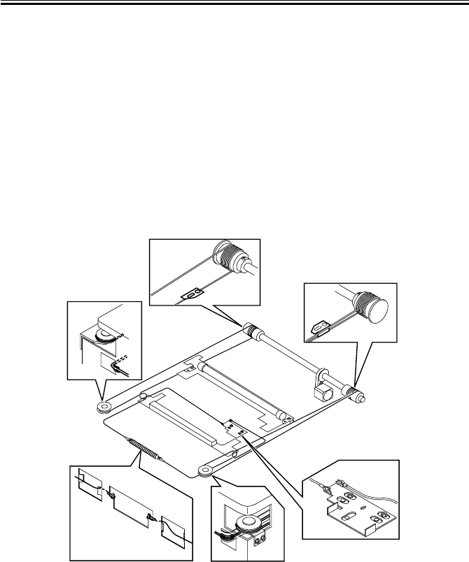
COPYRIGHT
©
2001 CANON INC. 2000 2000 2000 2000 CANON iR2200/iR2800/iR3300 REV.0 MAR. 2001
CHAPTER 3 STANDARDS AND ADJUSTMENTS
3-8 T
2.3 Routing the Scanner Drive Cable
Route the scanner cable as follows to the pulleys and the hook mirror base:
1) Loosen the screw on the cable fixing plate.
2) Put the ball of the cable into the hole in the drive pulley, and wind the cable firmly so
that it will not turn idly (4 runs inside, 5 runs outside); then, tape it in place. At this
time, check to make sure that the cable fixing is on the inside.
3) Engage the cable with each pulley, and temporarily fix one of its ends to the cable fixing
plate and the other to the hook on the reader frame.
4) Temporarily secure the cable fixing in place to the No. 1 mirror base. (Do not tighten the
screw fully.)
5) Fit the reader upper frame.
6) Adjust the position of the No. 1 and No. 2 mirror bases.
F02-203-01
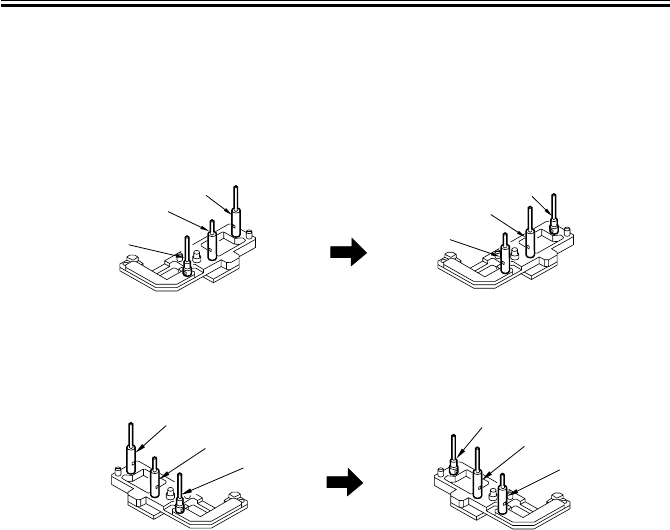
COPYRIGHT
©
2001 CANON INC. 2000 2000 2000 2000 CANON iR2200/iR2800/iR3300 REV.0 MAR. 2001
CHAPTER 3 STANDARDS AND ADJUSTMENTS
3-9 T
2.4 Adjusting the Position of the No. 1/No. 2 Mirror Base
1) Set the pins of the mirror positioning
tool as indicated:
• For the Front (F marking)
(initial; FY9-3009) (set for the machine)
F03-204-01
• For the Rear (R marking)
(initial; FY9-3009) (set for the machine)
F03-204-02
[A]
[A]
[B]
[B]
[C]
[C]
[A]
[A]
[B]
[B]
[C]
[C]

COPYRIGHT
©
2001 CANON INC. 2000 2000 2000 2000 CANON iR2200/iR2800/iR3300 REV.0 MAR. 2001
CHAPTER 3 STANDARDS AND ADJUSTMENTS
3-10 T
2) Fit the pins of the mirror positioning
tool (front [2], rear [3]) into the holes
[1] of the rail and the No. 1/No. 2 mir-
ror base. The No. 2 mirror base is ad-
justed in keeping with the back-and-
froth movement of the cable fixing
plate.
Front Side (F marking)
F03-204-03
Rear Side (R marking)
F03-204-04
3) Fix the end of the cable (which is tem-
porarily secured on the hook of the
reader frame) in place using the spring.
4) Fully tighten the screw on the cable fix-
ing plate.
5) Fully tighten the screw on the cable fix-
ing so that it is secured on the No. 1
mirror base.
6) Detach the mirror positioning tool (2
pc.).
[2]
[1]
[3]
[1]
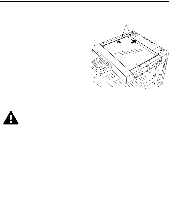
COPYRIGHT
©
2001 CANON INC. 2000 2000 2000 2000 CANON iR2200/iR2800/iR3300 REV.0 MAR. 2001
CHAPTER 3 STANDARDS AND ADJUSTMENTS
3-11 T
2.5 Mounting the Copyboard Glass
F03-205-01
• When mounting the
copyboard glass, butt the
copyboard glass [1] against
the vertical/horizontal size
plate [2]. If not done prop-
erly, the shadow of the size
plate will appear on images
made in enlargement mode.
(After mounting, make an
800% enlargement copy to
check.)
• Thereafter, execute optimum
position auto adjustment for
the standard white plate to
ensure correct shading correc-
tion:
COPIER>FUNCTION>CCD>SH-
PS-ST.
[2]
[1]
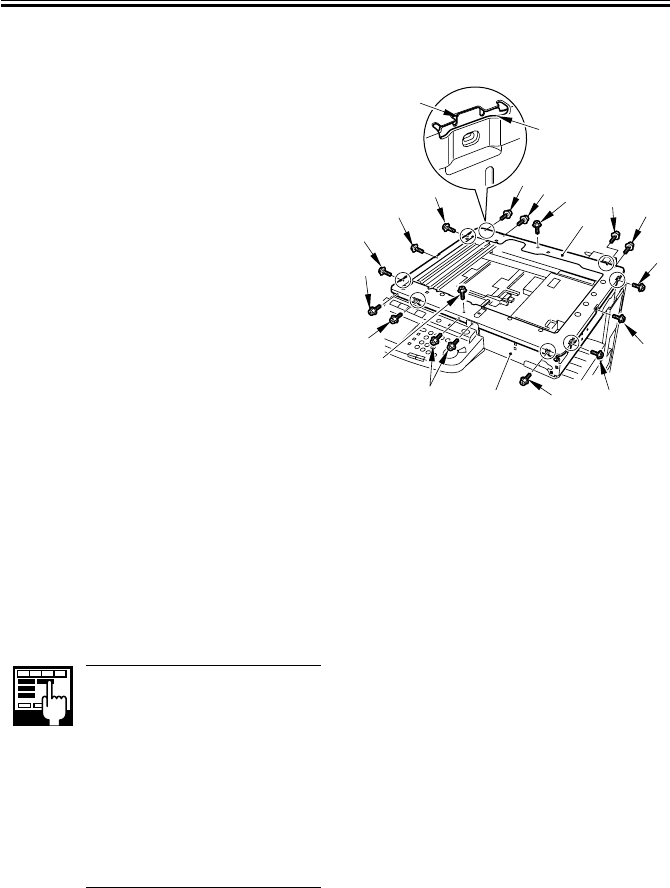
COPYRIGHT
©
2001 CANON INC. 2000 2000 2000 2000 CANON iR2200/iR2800/iR3300 REV.0 MAR. 2001
CHAPTER 3 STANDARDS AND ADJUSTMENTS
3-12 T
2.6 Mounting the Reader Upper Frame
1) Fit the eight claws [2] of the reader
frame [1] (circled) into the cut-offs [4]
in the reader upper frame [3]; take care
so that the engagement is secure.
2) Fit the eight screws [5] of the claw as-
sembly first.
3) Fit the seven screws [6] of the side.
4) Lastly, fit the two screws [7] on the top
face.
F03-206-01
2.7 Points to Note When Replacing the CCD Unit
Execute ‘CCD auto adjustment’ and
‘edge gain correction position auto adjust-
ment’ in service mode; then, record the up-
dated CCD adjustment data on the service
label.
1) CCD Auto Adjustment
COPIER>FUNCTION>CCD>
CCD-ADJ
2) Edge Gain Correction Auto
Adjustment
COPIER>FUNCTION>
CCD>EGGN-POS
3) CCD Adjustment Data
all items under
COPIER>ADJUST>CCD
2.8 When Replacing the Reader Controller PCB
See “Troubleshooting” > Chapter 3 “Standards and Adjustment” > 7. “Electrical Compo-
nents”
[4]
[2]
[7]
[7]
[5] [6]
[5]
[6]
[5]
[5]
[6]
[6] [5]
[6]
[6]
[5]
[5]
[3]
[1] [5]
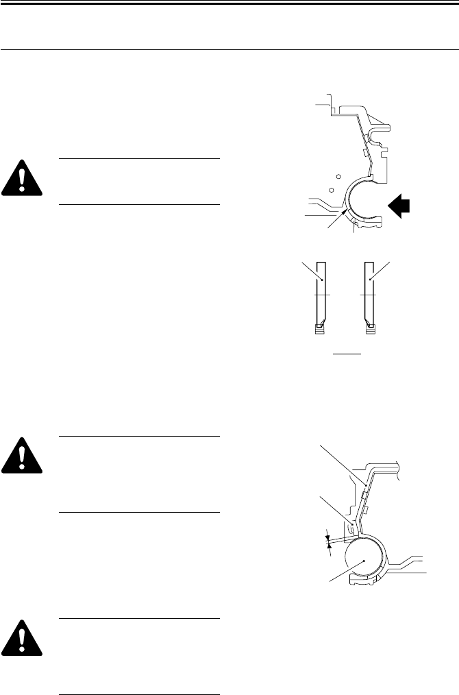
COPYRIGHT
©
2001 CANON INC. 2000 2000 2000 2000 CANON iR2200/iR2800/iR3300 REV.0 MAR. 2001
CHAPTER 3 STANDARDS AND ADJUSTMENTS
3-13 T
3 Image Formation System
3.1 Positioning the Developing Assembly Magnetic Seal
1) The front magnetic seal [1] and the rear
magnetic seal [2] must be butted against
the opening [3] (stop reference) when
they are mounted.
Check to make sure that the
magnetic seal is in firm contact
with the casing.
F03-301-01
3.2 Mounting the Developing Assembly Blade
The blade [1] and the blade base
[2] of the blade base unit are ad-
justed to a high accuracy at the
factory. Do not disassemble the
unit.
If you happen to have removed the blade,
adjust its position so that the gap between
the blade and the developing cylinder [3] is
0.21 ± 0.03 mm using a gap gauge (CK-
0057-000). F03-302-01
The surface of the developing
cylinder is highly susceptible to
scratches. Be sure to fit the gap
gauge on ends of the developing
cylinder.
A
A
[1]
[2]
[3]
[1] ([2])
[1]
[2]
[3]
0.21±0.03mm
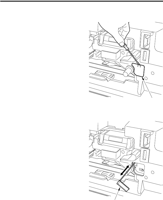
COPYRIGHT
©
2001 CANON INC. 2000 2000 2000 2000 CANON iR2200/iR2800/iR3300 REV.0 MAR. 2001
CHAPTER 3 STANDARDS AND ADJUSTMENTS
3-14 T
3.3 Removing the Paper Lint
1) Open the front cover.
2) Remove the paper lint cleaning cover
[1] by inserting a flat-blade screwdriver.
F03-303-01
3) Slide out the paper lint cleaning lever
[1], and move it back and forth.
F03-303-02
[1]
[1]
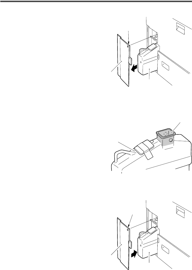
COPYRIGHT
©
2001 CANON INC. 2000 2000 2000 2000 CANON iR2200/iR2800/iR3300 REV.0 MAR. 2001
CHAPTER 3 STANDARDS AND ADJUSTMENTS
3-15 T
3.4 Cleaning the Waste Toner Case
1) Remove the screw [1], and detach the
waste toner case cover [2].
2) Take out the waste toner case [3].
F03-304-01
3) Dispose of the waste toner collecting
inside the waste toner case.
4) Clean both inside and the outside of the
waste toner case [1] (area A, indicated
by shading) with alcohol.
F03-304-02
5) Fit the waste toner case [1] back in the
machine, and mount the waste toner
case cover [2] with a screw [3].
F03-304-03
[1]
[2]
[3]
[1]
A
[3]
[2]
[1]
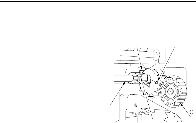
COPYRIGHT
©
2001 CANON INC. 2000 2000 2000 2000 CANON iR2200/iR2800/iR3300 REV.0 MAR. 2001
CHAPTER 3 STANDARDS AND ADJUSTMENTS
3-16 T
4 Fixing System
4.1 Mounting the Locking Cam Unit
1) Check to see if the feeding assembly is
locked in place.
2) Match the arrow of the gear of the lock-
ing cam unit [1] against the middle of
the gear [3] of the fixing drive unit (e.i.,
where the rear [4] of the gear of the
locking cam unit is in contact with the
cut-up [5] of the frame).
F03-401-01
[4] [3]
[1]
[5] [2]
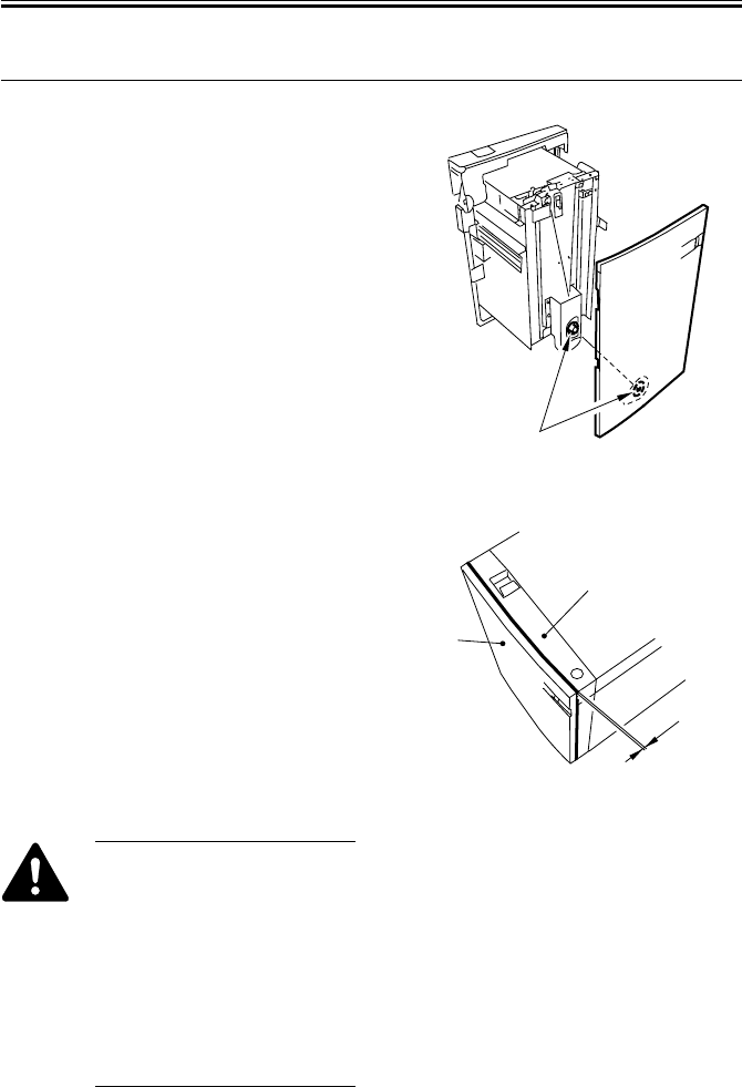
COPYRIGHT
©
2001 CANON INC. 2000 2000 2000 2000 CANON iR2200/iR2800/iR3300 REV.0 MAR. 2001
CHAPTER 3 STANDARDS AND ADJUSTMENTS
3-17 T
5 Paper Deck
5.1 Mounting the Front Cover
1) When mounting the front cover, be sure
to match it against the coupling [1] of
the paper level indicator.
F03-501-01
2) Be sure to mount the front cover so that
gap A between the front cover [1] and
the front upper cover [2] is 3 ±1 mm.
F03-501-02
If you operate the deck without
matching the position of the pa-
per level indicator and the deck
lifter, the drive mechanism of
the paper level indicator can be-
come damaged. If you have
moved the paper level indicator
drive belt behind the front cover
or the deck lifter, be sure to per-
form the following two tasks:
[1]
[1]
[2]
A
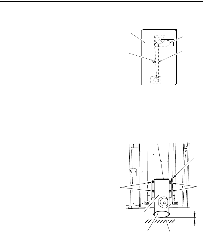
COPYRIGHT
©
2001 CANON INC. 2000 2000 2000 2000 CANON iR2200/iR2800/iR3300 REV.0 MAR. 2001
CHAPTER 3 STANDARDS AND ADJUSTMENTS
3-18 T
5.2 Adjusting the Paper Level Indicator
1) Move the drive belt [2] of the paper
level indicator behind the front cover
[1] by hand so that the white area inside
the window [3] increases, i.e., in the di-
rection for the arrow [4]; move it until a
little resistance is felt.
F03-502-01
5.3 Adjusting the Position of the Support Member
If the compartment cannot be opened/
closed smoothly and the position of the sup-
port roller must be adjusted, perform the
following:
1) Remove the front cover.
2) Using the four screws [4] of the roller
support plate [3], make adjustments so
that the support roller [1] and the floor
[2] is about 3 mm when the compart-
ment is fully slid out. (At this time, use
the scale [5] on the front side plate as a
reference.)
F03-503-01
[1]
[2]
[3]
[4]
[4]
[5]
[2]
[1]
[3] A
[4]
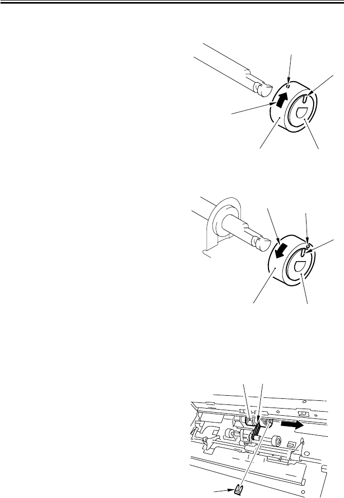
COPYRIGHT
©
2001 CANON INC. 2000 2000 2000 2000 CANON iR2200/iR2800/iR3300 REV.0 MAR. 2001
CHAPTER 3 STANDARDS AND ADJUSTMENTS
3-19 T
5.4 Mounting the Deck Pickup Roller
Body Front (collar: silver-colored)
When mounting the deck pickup roller
[2] to the front of the machine, be sure
that the marking [4] on the collar [3] is
toward the front of the machine and the
marking [5] on the side of the roller is to-
ward the rear of the machine.
F03-504-01
Body Rear (collar: gold-colored)
When mounting the deck pickup roller
[2] to the rear of the machine, be sure that
the marking [4] on the collar [3] and the
marking [5] on the side of the roller are
toward the rear of the machine.
F03-504-02
5.5 Removing the Deck Pickup/Feeding Roller
1) Remove the deck pickup unit. (p. 8-
36P)
2) Turn over the deck pickup unit.
3) Remove the resin ring [1], and detach
the deck pickup/feeding roller [2] and
the drive belt [3] to the front.
F03-505-01
[2] [3]
[3]
[3]
[1]
[4]
[5]
[1]
[2] [3]
[2] [3]
[1]
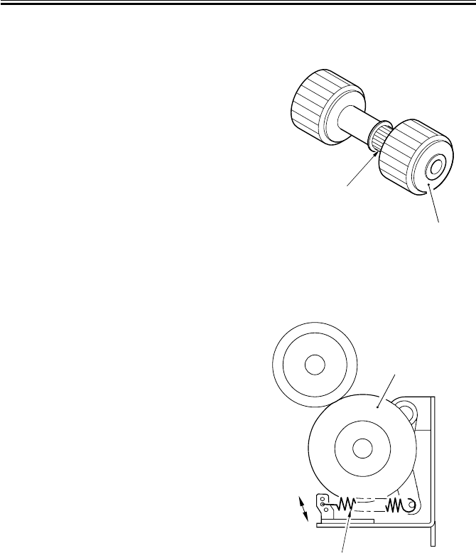
COPYRIGHT
©
2001 CANON INC. 2000 2000 2000 2000 CANON iR2200/iR2800/iR3300 REV.0 MAR. 2001
CHAPTER 3 STANDARDS AND ADJUSTMENTS
3-20 T
5.6 Orientation of the Deck Pickup/Feeding Roller
When mounting the deck pickup/feeding
roller [1], be sure that the belt pulley [2] is
toward the front of the machine.
The pickup/feeding roller rubber, on the
other hand, may be attached to the pickup/
feeding roller shaft in either orientation.
F03-506-01
5.7 Adjusting the Deck Separation Roller Pressure
If double feeding or pickup failure occurs
when the deck is used as the source of pa-
per, move the position of the pressure
spring [2] of the deck separation roller [1].
• If pickup failure occurs, move the
spring in the direction of arrow A.
• If double feeding occurs, move the
spring in the direction of arrow B.
F03-507-01
[1]
[2]
A
B
[1]
[2]
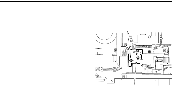
COPYRIGHT
©
2001 CANON INC. 2000 2000 2000 2000 CANON iR2200/iR2800/iR3300 REV.0 MAR. 2001
CHAPTER 3 STANDARDS AND ADJUSTMENTS
3-21 T
5.8 Position of the Deck Pickup Roller Releasing Solenoid
(SL1D)
Before detaching the deck pickup roller
releasing solenoid [1] from the support
plate, keep note of the position of the sole-
noid with reference to the two fixing screws
[2] on the solenoid. Or, mark the position of
the solenoid on the support plate with a
scribe to indicate the position. The solenoid
must always be positioned in its initial loca-
tion.
F03-508-01
[1]
[2]
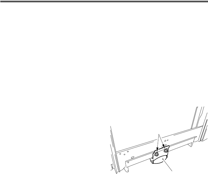
COPYRIGHT
©
2001 CANON INC. 2000 2000 2000 2000 CANON iR2200/iR2800/iR3300 REV.0 MAR. 2001
CHAPTER 3 STANDARDS AND ADJUSTMENTS
3-22 T
5.9 Adjusting the Height of the Side Member
5.9.1 Before Making Adjustments
1) Disconnect the machine from its host
machine, and then connect it once gain,
thereby finding out whether the impact
of connection causes the host machine
to slide over or the machine to wobble.
If any such problem is noted, adjust the
height of the side member as follows;
otherwise, these steps need not be per-
formed:
5.9.2 Making Adjustments
1) Connect the machine to the host ma-
chine.
2) Take out the paper from the deck.
3) Remove the right cover of the machine.
4) Loosen the two fixing screws [2] of the
side member [1].
5) With the side member in contact with
the floor, tighten the fixing screws. At
this time, refer to the index so that the
left and right screws match against the
same index.
F03-509-01
6) Disconnect the machine from the host
machine, and then connect it once
again. If it can be done without extra
force, mount the right cover for the ma-
chine, and put the paper back into the
deck. If extra force is needed, go to the
next step.
7) Check the index of the side member.
8) Loosen the fixing screws of the side
member.
9) While referring to the index, raise the
side member 1 mm, and then tighten the
fixing screws.
10) Mount the right cover, and then put the
paper back into the deck.
[1]
[2]

COPYRIGHT
©
2001 CANON INC. 2000 2000 2000 2000 CANON iR2200/iR2800/iR3300 REV.0 MAR. 2001
CHAPTER 3 STANDARDS AND ADJUSTMENTS
3-23 T
6 Cassette Feeding Unit-W1
6.1 Mounting the Pedestal Main Motor
1) When mounting the pedestal main mo-
tor, be sure to tighten the screws in the
order indicated in the figure: (1)
through (4).
F03-601-01
(1) (4)
(2)
(3)
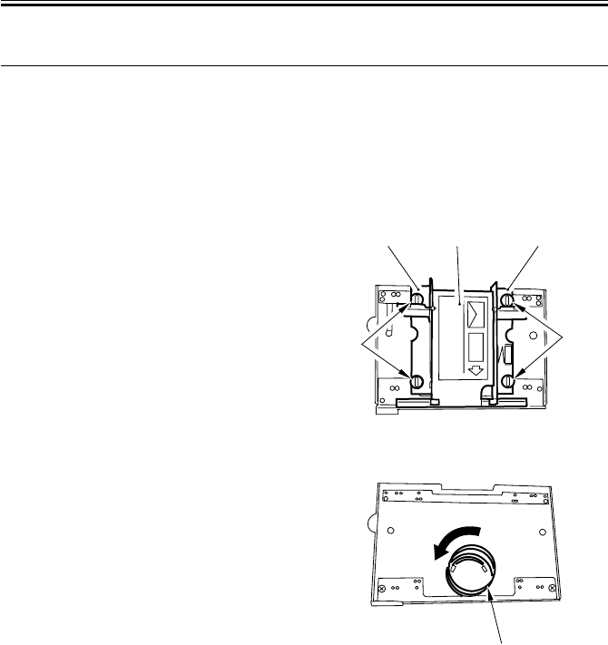
COPYRIGHT
©
2001 CANON INC. 2000 2000 2000 2000 CANON iR2200/iR2800/iR3300 REV.0 MAR. 2001
CHAPTER 3 STANDARDS AND ADJUSTMENTS
3-24 T
7 Envelope Feeder Attachment
7.1 Envelopes and Type of Spring
• Use the green-painted spring for COM10, Monarch, DL, and YOUKEI 4.
• Use the red-painted spring for C5 and B5.
7.2 Replacing the Spring
7.2.1 Replacing the Spring
1) Remove the two mounting screws [1]
each, and detach the side guide plate [2]
(front, rear) and the lifter [3].
F03-702-01
2) Holding the bottom (1st, 2nd loops) of
the spring [1], turn it clockwise to free
it from the envelope feeder.
F03-702-02
[2] [3] [2]
[1] [1]
[1]

COPYRIGHT
©
2001 CANON INC. 2000 2000 2000 2000 CANON iR2200/iR2800/iR3300 REV.0 MAR. 2001
CHAPTER 3 STANDARDS AND ADJUSTMENTS
3-25 T
3) Thread the edge of the spring [1] that
comes as an attachment so as to fit it
through the catch 1 [2] and then the
catch 2 [3].
4) Holding the bottom (1st and 2nd loops)
of the spring, fit it through the catch 3
[4]; then, thread it until distance A is
about 15 mm from the catch 2 [3].
At this time, check to make sure that the
spring is firmly on the bottom plate.
F03-702-03
7.3 Changing the Size
7.3.1 Changing the Size
1) Match the lifter [1] and the side guide
plate [2] against the size positioning
line of the envelope feeder in relation to
the edges of the side guide plate; then,
secure them in place by using two
mounting screws [3] each.
F03-703-01
Take care so that the side guide
plate will not extend beyond the
envelope feeder (as by choosing
the wrong mounting hole). See
the next page for the correct
mounting hole.
A
[2]
[1]
[3]
[4]
[3] [3]
[2] [1] [2]
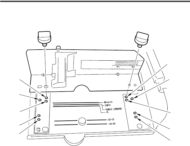
COPYRIGHT
©
2001 CANON INC. 2000 2000 2000 2000 CANON iR2200/iR2800/iR3300 REV.0 MAR. 2001
CHAPTER 3 STANDARDS AND ADJUSTMENTS
3-26 T
Mounting Hole by Side Guide Plate (front)
(The side guide rear is symmetrically opposite.)
F03-703-02
2) Register the specifications of the enve-
lope using ‘register envelope’ offered as
part of common settings.
3) Check to make sure that envelopes are
fed correctly.
[1] Monarch
[2] COM10, YOUKEI 4
[3] DL
[4] ISO-C5
[5] ISO-B5
[3]
[4]
[5]
[2]
[1]
[3]
[4]
[5]
[2]
[1]

COPYRIGHT
©
2001 CANON INC. 2000 2000 2000 2000 CANON iR2200/iR2800/iR3300 REV.0 MAR. 2001
CHAPTER 4
TROUBLESHOOTING IMAGE FAULTS/
MALFUNCTIONS

COPYRIGHT
©
2001 CANON INC. 2000 2000 2000 2000 CANON iR2200/iR2800/iR3300 REV.0 MAR. 2001
CHAPTER 4 TROUBLESHOOTING IMAGE FAULTS/MALFUNCTIONS
4-1 T
1 Making Initial Checks
1.1 Checking the Site of Installation
1. There must be a source of power rated as indicated (rated voltage ± 10%). The source
must be exclusively of the machine, and the power plug must remain connected through-
out the night.
2. The machine must not be in a high-temperature/-humidity area (near a water faucet, wa-
ter boiler, humidifier), must not be cold or subject to dust. There must not be a source of
fire nearby.
3. The machine must not be subjected to ammonium gas.
4. The machine must not be subjected to the direct rays of the sun; as necessary, curtains
must be provided.
5. The room must be well ventilated.
6. The floor must be flat to keep the machine level.
7. The source of power must provide power night and day.
Check the sight against the above requirements.
1.2 Checking the Originals
Check to find out if the symptom is caused by the originals used or by the machine:
1. The copy density is optimum if set to index 5 ± 1.
2. Originals with a reddish tone tend to prevent reproduction of good contrast.
3. Originals of specific densities can produce copies that can be mistaken as faulty.
Memo
• An original with a reddish tint can produce copies with poor contrast.
• Diazo copies used as originals or originals with a high degree of trans-
parency can produce copies that can be mistaken as “light copies.”
• Originals prepared in pencil or with a greenish tint can produce copies
that can be mistaken as “light copies.”
1.3 Checking the ADF Platen, Copyboard cover, and
Copyboard glass (standard white plate)
If the ADF platen, copyboard cover, or copyboard glass is soiled, clean it with a solution
of mild detergent; if scratched, replace it.

COPYRIGHT
©
2001 CANON INC. 2000 2000 2000 2000 CANON iR2200/iR2800/iR3300 REV.0 MAR. 2001
CHAPTER 4 TROUBLESHOOTING IMAGE FAULTS/MALFUNCTIONS
4-2 T
1.4 Charging Roller and Static Eliminator
1. Check the transfer charging roller and the separation static eliminator for dirt and a fault
(damage).
2. Check to make sure that the transfer charging roller and the separation static eliminator
are correctly mounted.
1.5 Checking the Developing Assembly
1. Check to make sure that the members on both ends of the drum are in contact. Other-
wise, light images can result.
2. Check to see the surface of the developing cylinder is coated with an even layer of toner.
Otherwise, light images or uneven density can result.
1.6 Checking the Paper
1. Check to see if the paper used is of a recommended type. Advise the user that paper not
of a recommended type may fail to bring about expected results.
2. Check to see if the paper is moist. Moist paper can adversely affect transfer, causing
poor images or separation faults (leading to jams and wrinkles). Advise the user on the
correct method of storing paper.
1.7 Checking the Periodically Replaced Parts
Check with the scheduled servicing chart and the table of periodically replaced parts. Re-
place parts that have reached the ends of their lives.
1.8 Image Adjustment Basic Procedure
If the copies have uneven density (difference between front and rear), light images, or
foggy background, try the Image Adjustment Basic Procedure first to see if the problem is
corrected.

COPYRIGHT
©
2001 CANON INC. 2000 2000 2000 2000 CANON iR2200/iR2800/iR3300 REV.0 MAR. 2001
CHAPTER 4 TROUBLESHOOTING IMAGE FAULTS/MALFUNCTIONS
4-3 T
1.9 Others
In winter, bringing a machine from a cold to warm place can cause condensation inside
the machine, causing various problems.
Memo
1. Condensation in the optical system (glass, mirror, lens) can cause dark
images.
2. Condensation in the charging system can cause leakage.
3. Condensation on the pickup/feeding guide can cause feeding faults.
If condensation is noted, dry wipe the part, or leave the machine pow-
ered and alone for 60 min.

COPYRIGHT
©
2001 CANON INC. 2000 2000 2000 2000 CANON iR2200/iR2800/iR3300 REV.0 MAR. 2001
CHAPTER 4 TROUBLESHOOTING IMAGE FAULTS/MALFUNCTIONS
4-4 T
Blank Page

COPYRIGHT
©
2001 CANON INC. 2000 2000 2000 2000 CANON iR2200/iR2800/iR3300 REV.0 MAR. 2001
4-6 T
CHAPTER 4 TROUBLESHOOTING IMAGE FAULTS/MALFUNCTIONS
2 Samples of Image Faults

COPYRIGHT
©
2001 CANON INC. 2000 2000 2000 2000 CANON iR2200/iR2800/iR3300 REV.0 MAR. 2001
CHAPTER 4 TROUBLESHOOTING IMAGE FAULTS/MALFUNCTIONS
4-7 T
3 Troubleshooting Image Faults
3.1 The copy is too light (halftone area only).
1) Perform the Image Adjustment Basic Procedure. Is the problem cor-
rected?
Check to make sure that the placement of the pattern print when the follow-
ing is executed in service mode is correct: FUNCTION>DENS>PD-ME.
YES: End.
AE adjustment
2) Make copies in AE mode. Is the text too light?
YES: Execute AE adjustment:
Decrease the setting of the following in service mode:
COPIER>ADJUST>AE>AE-TBL.
Developing assembly
3) Are the block members of the developing assembly in contact with the
photosensitive drum?
NO: Check the developing assembly locking lever. Check the surface of
the developing assembly block members for foreign matter (toner).
Developing assembly
4) Is the coating on the developing cylinder even?
NO: Check the developing assembly.
Scanner, Photosensitive drum
5) Clean the mirrors and lenses. Is the problem corrected?
YES: End.
NO: Replace the drum unit.

COPYRIGHT
©
2001 CANON INC. 2000 2000 2000 2000 CANON iR2200/iR2800/iR3300 REV.0 MAR. 2001
CHAPTER 4 TROUBLESHOOTING IMAGE FAULTS/MALFUNCTIONS
4-8 T
3.2 The copy is too light (including solid black).
1) Perform the Image Adjustment Basic Procedure. Is the problem cor-
rected?
Check to make sure that the placement of the pattern print when the follow-
ing is executed in service mode is correct: FUNCTION>DENS>PD-ME.
YES: End.
2) Turn off the main power switch in the middle of copying operation, and
open the front cover. Is the toner image on the photopositive drum before
transfer more or less normal?
NO: Go to step 7.
Feeding unit (Transfer charging roller)
3) Is the feeding unit locked in place correctly?
NO: Check the transfer charging roller pressure spring.
4) Is there electrical leakage around the electrode of the feeding unit?
YES: Check the electrode of the feeding unit.
5) Is there dirt, cracking, or scratching on the transfer charging roller?
YES: Replace the transfer charging roller.
6) Are the position and the condition of the transfer charging roller locking
spring normal?
NO: Correct the position of the spring, or replace the spring.
Paper (transfer faulty)
7) Try paper fresh out of package. Is the problem corrected?
YES:
• The paper may be moist. Advise the user on the correct method of
storing paper.
• Advise the user that the use of paper not of a recommended type
may fail to produce poor images.

COPYRIGHT
©
2001 CANON INC. 2000 2000 2000 2000 CANON iR2200/iR2800/iR3300 REV.0 MAR. 2001
CHAPTER 4 TROUBLESHOOTING IMAGE FAULTS/MALFUNCTIONS
4-9 T
Transfer guide, High-voltage cord, Composite power supply PCB, DC controller PCB
(transfer faulty)
8) Is there foreign matter in the transfer guide assembly or the transfer
charging roller assembly, and is leakage noted?
YES: Remove the foreign matter.
NO:
1. Check the high-voltage cord for electrical continuity. (The resis-
tance of the transfer high-voltage cord is about 10 kΩ.)
2. Check the composite power supply PCB and the DC controller
PCB.
Developing assembly
9) Is the developing assembly fitted securely? (Check to see if the develop-
ing block members are in firm contact with the photosensitive drum.)
NO: Fit the developing assembly correctly.
Toner level detection assembly (development fault)
10)Is there toner inside the developing assembly?
NO:
• Check the toner sensor.
• Check the connectors and the harnesses for electrical continuity.
Drum unit, Reader controller PCB, Main controller PCB
11)Try replacing the drum unit. Is the problem corrected/
YES: End.
NO: Real the reader controller PCB and the main controller PCB.
Memo
• The resistance of the high-voltage cord for primary charging is about
10 kΩ
• The resistance of the high-voltage cord (white) is about 10 kΩ
• The resistance of the cord for the transfer guide is about 10 kΩ

COPYRIGHT
©
2001 CANON INC. 2000 2000 2000 2000 CANON iR2200/iR2800/iR3300 REV.0 MAR. 2001
CHAPTER 4 TROUBLESHOOTING IMAGE FAULTS/MALFUNCTIONS
4-10 T
3.3 The copy is too light (entire face, considerable).
1) Perform the Image adjustment Basic Procedure. Is the problem cor-
rected?
Check to make user that the placement of the pattern print when executing
the folding is correct: FUNCTION>DENS>PD-ME.
YES: End.
AE adjustment
2) Turn off the main power switch in the middle of copying operation, and
open the front cover. At this time, is the toner image on the surface of the
photosensitive drum before transfer more or less normal?
NO: Go to step 5.
Developing assembly
3) Are the developing members in firm contract with the drum?
NO: Check the developing assembly locking lever. Check the surface of
the developing members for foreign matter (toner).
Developing clutch
4) Is the developing cylinder rotating?
NO: Check the developing clutch (for a lose hex screw).
Feeding unit (tranfer charging roller)
5) Is the feeding unit locked in place correctly?
Is the transfer roller in contact with the photosensitive drum whet the feed-
ing unit is locked in place?
NO:
• Check the transfer charging roller pressure spring.
• Check the feeding locking assembly.
6) Is there leakage in the electrode assembly of the feeding unit?
YES: Check the electrode assembly of the feeding unit.
High-voltage cord, Feeding unit (Transfer charging roller)
7) Is the feed electric continuity from the composite power supply PCB to
the electrode assembly of the feeding unit? (The resistance of the high-volt-
age cord of the transfer charging roller is about 10 kΩ.)
NO:
• Replace the high-voltage cord.
• Check the feeding unit.
Composite power supply PCB, DC controller PCB
8) Is there electrical continuity from the composite power supply PCB to
the feeding unit? (The resistance of the high-voltage cord of the transfer
charging roller is about 10 kΩ.)
YES: Check the composite power supply PCB and the DC controller
PCB.

COPYRIGHT
©
2001 CANON INC. 2000 2000 2000 2000 CANON iR2200/iR2800/iR3300 REV.0 MAR. 2001
CHAPTER 4 TROUBLESHOOTING IMAGE FAULTS/MALFUNCTIONS
4-11 T
Transfer guide
9) Is there foreign matter in the transfer guide assembly or the transfer
charging roller assembly, and is there electrical leakage?
YES: Remove the foreign matter.
Paper
10)Is there foreign matter in the transfer guide assembly or the transfer
charging roller, and is there leakage?
NO: Try fresh paper or paper of a different type.
Development (fault)
11)Is the developing assembly in firm contact with the photosensitive
drum? (Check to see that the developing block members are in firm contact
with the photosensitive drum.)
NO: Fit the developing assembly once again.
YES:
• Check the developing assembly.
• Check the developing bias.

COPYRIGHT
©
2001 CANON INC. 2000 2000 2000 2000 CANON iR2200/iR2800/iR3300 REV.0 MAR. 2001
CHAPTER 4 TROUBLESHOOTING IMAGE FAULTS/MALFUNCTIONS
4-12 T
3.4 The copy has uneven density (darker at front).
3.5 The copy has uneven density (lighter at front).
Developing assembly
1) Are the developing block members of the developing assembly in firm
contact with the developing assembly?
NO: Check the developing assembly locking unit.
Scanner
2) Clean the scanning lamp, reflecting plate, mirrors, and lenses. Is the
problem corrected?
YES: End.
Pre-exposure lamp
3) Is the pre-exposure lamp ON during copying operation?
NO:
1. Replace the pre-exposure lamp unit.
2. Replace the DC controller PCB.
Developing assembly
4) Is the coating of toner on the developing cylinder even?
NO:
1. Clean the tip of the blade of the developing assembly. (dry wiping)
2. Clean the surface of the developing cylinder.
3. Check the toner inside the developing assembly for uneven deposit.
5) Try the following modes. Is the problem corrected?
• APVC adjustment once gain in service mode: FUNCTION>DPC>D-
GAMMA.
• ATVC adjustment once again in user mode: ‘roller clean’ under ‘adjust/
clean’.
YES: End.
Drum cartridge, Shading
6) Is there an uneven image in the halftone area of PG?
YES: Replace the drum unit.
NO: Execute shading adjustment (i.e., FUNCTION>CCD>CCD-ADJ).

COPYRIGHT
©
2001 CANON INC. 2000 2000 2000 2000 CANON iR2200/iR2800/iR3300 REV.0 MAR. 2001
CHAPTER 4 TROUBLESHOOTING IMAGE FAULTS/MALFUNCTIONS
4-13 T
3.6 The copy is foggy (entire face).
Scanner
1) Clean the scanning lamp, reflecting plate, mirrors, and lenses. Is the
problem corrected?
YES: End.
2) Perform the Image Adjustment Basic Procedure. Is the problem cor-
rected?
YES: End.
3) Select the following in service mode, and press the OK key:
COPIER>FUNCTION>DPC>D-GAMAM. Is the problem corrected?
NO: Replace the drum unit. However, be sure to take appropriate mea-
sures, as a fault in the following is suspected: main controller PCB,
DC controller PCB, composite power supply PCB.
Developing assembly
4) Is the developing cylinder insulated from the GND of the machine?
(Turn off the main power switch, and disconnect the connector J130 of the
composite power supply PCB; then, check the length between J130-1 and
the metal plate of the host machine for electrical continuity.)
NO: Check the area around the developing cylinder and the develop-
ment connectors.
High-voltage system
5) Is PG solid white foggy?
YES: Check the high-voltage system.
Service mode
6) Adjust the setting of the following up to +30 of the factory value:
ADJUST>DEVELOP>DE-OFST. Is the problem corrected?
YES: End.
Developing bias, DC controller PCB
7) Try replacing the composite power supply. Is the problem corrected?
YES: End.
NO: Replace the DC controller PCB.

COPYRIGHT
©
2001 CANON INC. 2000 2000 2000 2000 CANON iR2200/iR2800/iR3300 REV.0 MAR. 2001
CHAPTER 4 TROUBLESHOOTING IMAGE FAULTS/MALFUNCTIONS
4-14 T
3.7 The copy is foggy (vertical).
3.8 The copy has a black line (vertical, fuzzy, thick).
Primary charging roller
1) Clean the charging roller in user mode. Is the problem corrected?
YES: End.
Scanner
2) Clean the mirrors and lenses. Is the problem corrected?
YES: End.
Developing assembly
3) Is the coating of toner on the developing cylinder even?
NO:
1. Check the edge of the blade of the developing assembly.
2. Dry wipe the surface of the developing cylinder.
Photosensitive drum, External light
4) Is there a scratch in the peripheral direction on the surface of the photo-
sensitive drum?
YES: Replace the drum unit.
NO: Check to see if the photosensitive drum is subjected to light from
outside.

COPYRIGHT
©
2001 CANON INC. 2000 2000 2000 2000 CANON iR2200/iR2800/iR3300 REV.0 MAR. 2001
CHAPTER 4 TROUBLESHOOTING IMAGE FAULTS/MALFUNCTIONS
4-15 T
3.9 The copy has a black line (vertical, fine).
Exposure system
1) Generate a halftone test print in service mode. Enter ‘5’ to
COPIER>PG>TYPE. Does the output image have a black line?
NO: Suspect a fault in the exposure system. Clean it.
Primary charging roller
2) Clean the primary charging roller. Is the problem corrected?
YES: End.
Photosensitive drum
3) Is there a scratch or a black line in the peripheral direction of the surface
of the photosensitive drum?
• Be sure to wipe the black line on the surface of the photosensitive drum
with a cloth coated with toner, and make sure that the black line disappears.
NO: Replace the drum unit.
• If there is a scratch, be sure to identify the cause.
Fixing assembly
4) Is there a scratch it the peripheral direction of the fixing roller?
YES: Replace the fixing roller.
NO: Check the fixing inlet assembly for dirt.

COPYRIGHT
©
2001 CANON INC. 2000 2000 2000 2000 CANON iR2200/iR2800/iR3300 REV.0 MAR. 2001
CHAPTER 4 TROUBLESHOOTING IMAGE FAULTS/MALFUNCTIONS
4-16 T
3.10 The copy has a white spot (vertical).
3.11 The copy has a white line (vertical).
Exposure system
1) Generate a halftone test print in service mode. Enter ‘4’ to the following:
COPIER>PG>TYPE. Does the output image have a white line/spot?
NO: Go to step 7.
dirt (lint)
2) Is there dirt (lint) in the drum unit or around the laser optical path of the
developing assembly?
YES: Remove the dirt (lint).
Transfer charging roller, Separation static eliminator
3) Is the transfer charging roller or the separation static eliminator soiled or
coated with foreign matter?
YES: Clean the transfer charging roller or the separation static elimina-
tor. If the problem is still not corrected, replace the transfer charg-
ing roller or the separation static eliminator.
Developing assembly
4) Is the coating of toner on the developing cylinder even?
NO: Check the edge of the developing assembly. If the developing as-
sembly is without toner, see the descriptions under “The Add Toner
message fails to go ON.”
Fixing film
5) Is there a scratch in the peripheral direction of the fixing film?
YES: Replace the fixing film unit
Fixing assembly inlet
6) Is there dirt or foreign matter on the fixing assembly inlet?
YES: Clean the inlet.
Photosensitive drum
7) Is there a scratch in the peripheral direction of the photosensitive drum?
YES: Replace the drum unit.
• Be sure to identify the cause of the scratch.
Exposure system, Standard white plate
8) Clean the copyboard glass (stander white plate) and the mirrors. Is the
problem corrected?
YES: End.
NO: Change the setting in the following service mode to change the
point of shading measurement: FUNCTION>SHDG-POS. If the
problem is not corrected after several attempts, replace the
copyboard glass.

COPYRIGHT
©
2001 CANON INC. 2000 2000 2000 2000 CANON iR2200/iR2800/iR3300 REV.0 MAR. 2001
CHAPTER 4 TROUBLESHOOTING IMAGE FAULTS/MALFUNCTIONS
4-17 T
3.12 The copy has a white spot (horizontal).
Exposure system
1) Generate a halftone test print in service mode. Enter ‘4’ to the following:
COPIER>PG>TYPE. Does the output image have a white spot?
NO: Go to step 4.
Developing assembly
2) Does the problem occur at intervals of about 35 mm?
YES:
• Clean the developing block members.
• Dry wipe the surface of the developing cylinder.
• If a scratch is found on the surface of the developing cylinder, re-
place the developing cylinder.
Drum unit
3) Does the problem occur at intervals of about 94 mm?
YES:
• Clean the drum.
• If a scratch is found on the drum, replace the drum unit.
Paper
4) Try paper fresh out of package.
YES: The paper may be moist. Advise the user on the correct method of
storing paper.
Transfer charging roller, Developing bias
5) Is there a white spot on the photosensitive drum during copying opera-
tion?
NO: Check the transfer charging roller for leakage.
YES: Check the developing bias.

COPYRIGHT
©
2001 CANON INC. 2000 2000 2000 2000 CANON iR2200/iR2800/iR3300 REV.0 MAR. 2001
CHAPTER 4 TROUBLESHOOTING IMAGE FAULTS/MALFUNCTIONS
4-18 T
3.13 The back of the copy is soiled/Soiled edge.
Exposure system
1) Turn off the main power switch while paper is moving in the feeding
assembly. At this time, is the back of the paper soiled?
NO: Go to step 5.
Transfer guide assembly
2) Does the back of paper soiled after replacing the drum that caused a
black line or the like?
YES: Clean the transfer guide.
Transfer guide bias, Transfer guide
3) During copying, is the voltage between the transfer guide (+) and the
machine side plate (-) about -50 to -650V?
NO:
• Check the transfer guide bias connector.
• Clean the transfer guide.
• Clean the bottom of the developing assembly.
Developing assembly, Registration roller, Drum cleaner
4) Does the problem occur at intervals of about 50 mm?
YES:
• Clean the registration roller.
• Clean the transfer guide.
• Check the developing assembly for leakage of toner.
• Clean the bottom of the developing assembly.
NO:
• Clean the feeding assembly.
• Clean the transfer guide.
• Check the drum cleaner assembly fro leakage of waste toner.
Transfer charging roller
5) Execute cleaning of the roller in user mode. Is the problem corrected?
YES: End.
Fixing assembly
6) Execute fixing cleaning mode in the following service mode:
COPIER>OPTION>BODY>FIX-CLN.
Is the problem corrected?
NO: Replace the fixing cleaning roller.
YES: End.

COPYRIGHT
©
2001 CANON INC. 2000 2000 2000 2000 CANON iR2200/iR2800/iR3300 REV.0 MAR. 2001
CHAPTER 4 TROUBLESHOOTING IMAGE FAULTS/MALFUNCTIONS
4-19 T
3.14 The copy has a fixing fault.
1) Does the problem occur when the machine is first turned on (as in the
morning)?
NO: Go to step 3.
2) Is the paper thick or the like, which has poor fixing quality?
YES: Select ‘thick paper’, and try feeding paper from the multifeeder.
Fixing film
3) Is the problem vertical?
YES: If a scratch is found on the fixing film, replace the film unit.
Fixing heater
4) Does the heater operate?
NO: See “The fixing heater fails to operate.”
Fixing lower roller pressure
5) Is the lower roller pressure (nip width) as indicated?
NO: Replace the fixing assembly.
Thermistor
6) Does the indication in the following service mode increase:
COPIER>DISPLAY>ANALOG>FIX-C?
NO: Replace the film unit.
Paper
7) Is the paper of a recommended type?
NO: Try paper of a recommended type. If the result is good, advise the
user to use paper of a recommended type.
Service mode
8) Set priority on fixing in the following service mode:
COPIER>OPTION>BODY>FIX-TEMP. Is the problem corrected?
YES: End.

COPYRIGHT
©
2001 CANON INC. 2000 2000 2000 2000 CANON iR2200/iR2800/iR3300 REV.0 MAR. 2001
CHAPTER 4 TROUBLESHOOTING IMAGE FAULTS/MALFUNCTIONS
4-20 T
3.15 The copy has a displaced leading edge.
3.16 The copy has a displaced leading edge (large margin).
3.17 The copy has a displaced margin (no margin).
1) Is an ADF used?
YES: Correct the displacement by referring to the Service Manual of the
ADF.
Original
2) Is the original placed correctly?
NO: Place the original correctly.
Pickup roller, Feeding roller, Separation roller
3) Has the pickup, feeding, or separation roller of the cassette in question
reached the end of its life?
YES: Check the roller; if worn, replace it.
REGIST
4) Execute the following in service mode: ADJUST>FEED-ADJ>REGIST.
Is the problem corrected? (Note 1)
YES: End.
Registration roller, Pickup/Feeding guide
5) Does the problem occur only in double-sided mode?
YES: Check the rollers of the duplex feeding assembly.
NO: Check and clean the following:
• Registration rollers
• Pickup/feeding guide
Note 1:
Making Adjustments
• Generate a PG test pattern ( [6] ; solid bal).
• Make adjustments so that the leading edge margin is 2.5 ± 1.5 mm. A higher setting
will decrease the margin.

COPYRIGHT
©
2001 CANON INC. 2000 2000 2000 2000 CANON iR2200/iR2800/iR3300 REV.0 MAR. 2001
CHAPTER 4 TROUBLESHOOTING IMAGE FAULTS/MALFUNCTIONS
4-21 T
3.18 The copy is blurred.
Scanner drive cable
1) Is the cable wound on the wire pulley twisted or twined when the scan-
ner is moving? Is there e foreign matter in the mirror pulley assembly?
YES:
• Route the cable correctly.
• Replace the cable.
• Remove the foreign matter.
Scanner rail
2) Move the No. 1 mirror base slowly by hand. Does it move smoothly?
NO: Clean the surface of the scanner rail with alcohol; thereafter, apply
a small amount of silicone oil.
Drum drive assembly, Photosensitive drum
3) Does the problem occur at intervals of about 94 mm?
YES:
• Check the drum drive assembly.
• Check the drum ends (where developing block members remain in
contact) for a scratch or foreign matter.
Developing gear, Drum drive assembly, Drum unit
4) Does the problem occur at intervals of about 35 mm?
YES: Check the developing assembly.
NO:
• Check the drum drive assembly.
• Replace the drum unit.

COPYRIGHT
©
2001 CANON INC. 2000 2000 2000 2000 CANON iR2200/iR2800/iR3300 REV.0 MAR. 2001
CHAPTER 4 TROUBLESHOOTING IMAGE FAULTS/MALFUNCTIONS
4-22 T
3.19 The copy is foggy (horizontal).
1) Does the problem occur at the same position on all copies made in Di-
rect.
YES: Go to step 5.
Scanning lamp
2) Does the scanning lamp flicker while the scanner is moving forward?
YES: Check the scanning lamp and the inverter PCB.
Drum unit
3) Does the problem occur at intervals of 94 mm?
YES: Replace the drum unit.
Wiring
4) Is the wiring between the scanning lamp, the inverter PCB and the
reader assembly?
NO: Correct the wiring.
Developing assembly
5) Is the coating of toner on the developing cylinder normal?
NO: Check the developing bias.
Scanner, Feeding system
6) Make reduced copies (about 50% to 60%), and compare them against
copies made in Direct. Is the position of the problem different?
YES: Check the scanner.
NO: Check the feeding assembly.

COPYRIGHT
©
2001 CANON INC. 2000 2000 2000 2000 CANON iR2200/iR2800/iR3300 REV.0 MAR. 2001
CHAPTER 4 TROUBLESHOOTING IMAGE FAULTS/MALFUNCTIONS
4-23 T
3.20 The copy has inadequate sharpness.
Copyboard glass
1) Is there oil or the like on the copyboard glass? Is there foreign matter on
the copyboard glass stay?
YES: Clean the copyboard glass.
Scanner
2) Clean the scanning lamp, reflecting plate, mirrors, and lenses. Is the
problem corrected?
YES: End.
Mirror (position)
3) Is the horizontal reproduction ratio in Direct as indicated?
NO: Adjust the position of the No. 1 mirror an the No. 2 mirror.
Developing bias
4) Are the connection and the electrical continuity of the high-voltage for
the developing bias normal? (The resistance of the cable for the developing
bias and the resistance between the terminal of the composite power supply
PCB and the terminal on the developing assembly is about 10 kΩ.)
NO: Check the connection; and replace the cable. If the problem is still
not corrected,
1. Replace the composite power supply PCB
2. Replace the DC controller PCB.
Drum unit, Transfer charging system
5) Try replacing the drum unit. Is the problem corrected?
YES: End.
NO: Check the transfer charging system.

COPYRIGHT
©
2001 CANON INC. 2000 2000 2000 2000 CANON iR2200/iR2800/iR3300 REV.0 MAR. 2001
CHAPTER 4 TROUBLESHOOTING IMAGE FAULTS/MALFUNCTIONS
4-24 T
3.21 The copy is completely blank.
Developing assembly
1) Is the developing assembly locked to the photosensitive drum during
copying?
NO: Check the locking mechanism of the developing assembly.
Developing assembly drive mechanism
2) Is the developing cylinder rotating during copying?
NO: Check the drive mechanism of the developing assembly.
3) Is the image of the test print (PG>TYPE; 1 through 8) normal?
YES: Go to step 10.
Transfer charging roller
4) Is the transfer charging roller mounted properly?
NO: Check the mounting condition.
5) Is leakage noted on the transfer charging roller?
YES: Check the transfer charging roller.
Transfer high-voltage cord
6) Is the connection of the transfer high-voltage cord normal? Is there elec-
trical continuity in the transfer high-voltage cord? (The resistance of the
transfer high-voltage cord is about 10 kΩ.)
NO:
• Connect the cord properly.
• Replace the transfer high-voltage cord.
DC controller PCB
7) Try replacing the DC controller PCB. Is the problem corrected?
YES: End.
Composite power supply PCB
8) Try replacing the composite power supply PCB. Is the problem cor-
rected?
YES: End.
Power supply (to CCD PCB)
9) Is about 12 VDC present on J602-1 of the CCD PCB? Is about 5 VDC
present on J602-4?
NO: Check the wiring; if normal, replace the reader controller PCB.

COPYRIGHT
©
2001 CANON INC. 2000 2000 2000 2000 CANON iR2200/iR2800/iR3300 REV.0 MAR. 2001
CHAPTER 4 TROUBLESHOOTING IMAGE FAULTS/MALFUNCTIONS
4-25 T
Wiring
10)Is the wiring between the CCD PCB and the reader controller PCB nor-
mal?
NO: Correct the wiring.
Laser scanner unit, Drum unit
11)Try replacing the drum unit. Is the problem corrected?
NO: Check the laser shutter mechanism; if normal, replace the laser
scanner unit.
YES: End.

COPYRIGHT
©
2001 CANON INC. 2000 2000 2000 2000 CANON iR2200/iR2800/iR3300 REV.0 MAR. 2001
CHAPTER 4 TROUBLESHOOTING IMAGE FAULTS/MALFUNCTIONS
4-26 T
3.22 The copy is completely black.
Scanning lamp
1) Is the scanning lamp ON during copying operation?
NO: See “The scanning lamp fails to go ON.”
Margin
2) Is there a margin on copies made in normal mode?
YES: Go to step 6.
NO: Go to step 3.
Drum unit
3) Is the drum unit fitted correctly? (Is it fully pushed inside?)
NO: Mount it correctly.
Primary charging roller
4) Are the contact of the connectors, connection of the harness, and electri-
cal continuity from J130-7 of the composite power supply PCB to the pri-
mary charring roller normal? (The resistance of the high-voltage cord for
primary charging is 10 kΩ.)
NO: Correct the fault.
Mirror (position)
5) Generate test prints (PG>TYPE; 1 through 8). At this time, is the image
on the photosensitive drum normal?
NO: Go to step 7.
DC controller PCB, Composite power supply PCB
6) Is the output of J301-B4 (+) on the DC controller PCB 0 V during copy-
ing operation?
NO: Replace the DC controller PCB.
YES: Replace the composite power supply PCB.
Reader controller PCB, CCD unit
7) Try replacing the CCD unit. Is the problem corrected?
NO: Replace the reader controller PCB.
YES: End.

COPYRIGHT
©
2001 CANON INC. 2000 2000 2000 2000 CANON iR2200/iR2800/iR3300 REV.0 MAR. 2001
CHAPTER 4 TROUBLESHOOTING IMAGE FAULTS/MALFUNCTIONS
4-27 T
3.23 The copy has a block/white dot after replacement of the
drum unit.
1) Execute the following in service mode: FUNCTION>DPC>D-
GAMMA. Then, make copies of the NA-3 Chart. Is the copy image nor-
mal?
YES: End.
Drum unit
2) Set the following to ‘1’: OPTION>BODY>PRIAC-SW. Then, make
copies of the NA-3 Chart. Is the copy image normal?
YES: End.
NO: Replace the drum unit.
3.24 The copy has a black line (stream reading).
Reading glass, Dirt
1) Does the problem occur on the same position on all copies?
YES: Check the reading glass for dirt and a scratch.
NO: Paper lint (droppings) can be suspected. Clean the ADF roller,
original path, and reading glass.

COPYRIGHT
©
2001 CANON INC. 2000 2000 2000 2000 CANON iR2200/iR2800/iR3300 REV.0 MAR. 2001
CHAPTER 4 TROUBLESHOOTING IMAGE FAULTS/MALFUNCTIONS
4-28 T
4 Troubleshooting Malfunctions
4.1 Power Supply System
4.1.1 The AC power is absent.
1. Initial checks
[1] Is the power plug connected to the power outlet?
[2] Is the rated AC voltage present at the power outlet?
[3] Has the leakage breaker gone ON?
2. Switch PCB, Wiring, Connector
Is the resistance 0 Ω when the switch is turned on and ∞Ω when it is turned
off?
NO: Replace the switch PCB.
YES: Check the AC power line (power cord, leakage breaker, switch
PCB, main power supply PCB (J6)) for poor wiring (i.e., electrical
continuity); check the connectors for poor contact.

COPYRIGHT
©
2001 CANON INC. 2000 2000 2000 2000 CANON iR2200/iR2800/iR3300 REV.0 MAR. 2001
CHAPTER 4 TROUBLESHOOTING IMAGE FAULTS/MALFUNCTIONS
4-29 T
4.1.2 The DC power is absent.
1. AC power supply
Is the rated AC voltage present at the connector J6 (between 1 and 3) of the
main controller PCB and at the connector J100 (between 1 and 3) of the
composite power supply PCB?
NO: See “The AC power is absent.”
2. Fuse (F1)
Is the fuse on the composite power supply PCB blown ?
YES: Remove the cause of the fuse, and replace the fuse.
3. Main power supply PCB, Composite power supply PCB
Is the output voltage of each power supply PCB normal?
a. Main Power Supply PCB b. Composite Power Supply
YES: Check the wiring from each power supply PCB to each load.
NO: Replace the faulty power supply PCB.
Connector
J202-1, 3, 5
J203-2
J204-1, 3, 7, 8, 9
J206-2
J206-3
Output voltage
24VU1-SW
24VU2
24VU3
24VU3
5V
Connector
J120-1, 4
J121-1, 2, 3
J121-4, 5
J121-11,12,13
J122-1, 2
J124-3, 4
J124-6
J124-9, 10
J126-2, 3, 5, 7
Output voltage
5V
3VA2
3VA1
3VB
5V
3VA1
3VB
5V
13V

COPYRIGHT
©
2001 CANON INC. 2000 2000 2000 2000 CANON iR2200/iR2800/iR3300 REV.0 MAR. 2001
CHAPTER 4 TROUBLESHOOTING IMAGE FAULTS/MALFUNCTIONS
4-30 T
4.2 Printer Unit
4.2.1 Pickup fails.
1. General condition
Slide out and then in the cassette. Is the sound of the lifter fall heard?
NO: See “The lifter fails to move up.”
2. Sensor
In service mode (COPIER>DISPLAY>JAM) find the sensor that detected
the jam. Is the sensor lever and the sensor itself normal?
NO: Replace the sensor lever or the sensor.
3. Releasing lever (for pickup/separation roller)
Push in the releasing lever toward the rear. Is the pickup roller released? Do
the feeding roller and the separation roller come into firm contact?
NO: The releasing lever (spring) is displaced or deformed. Correct or
replace it.
4. Pickup/feeding/separation roller
Execute pickup operation. Does the roller rotate?
YES: The movement of paper is faulty because of wear on the pickup/
feeding/separate roller. Replace the roller.
5. Pickup drive assembly
Is there damage/foreign matter on the gear of the pickup roller drive assem-
bly?
YES: Replace the gear. Remove the foreign matter.
6. Pickup motor (M2)
Execute the following in service mode: code 3 of
COPIER>FUNCTION>PART-CHK>MTR; i.e., MTR-ON. Is the motor
control signal present at J1602 of the pickup PCB? (J1602-1: A*, J1602-2:
A, J1602-3: B*, J1602-4: B)
YES: Replace the pickup motor.
7. Pickup PCB, DC controller PCB
Execute the following in service mode: code 3 of
COPIER>FUNCTION>PART-CHK>MTR; i.e., MTR-ON. Is the motor
control signal present at J302A of the DC controller PCB? (J302A-1: 24 V,
J302A-3: GND, J302A-6: IN1, J302A-7: IN2, J302A-8: IN3, J302A-8:
IN4)
YES: Replace the pickup PCB.
NO: Replace the DC controller PCB.

COPYRIGHT
©
2001 CANON INC. 2000 2000 2000 2000 CANON iR2200/iR2800/iR3300 REV.0 MAR. 2001
CHAPTER 4 TROUBLESHOOTING IMAGE FAULTS/MALFUNCTIONS
4-31 T
4.2.2 The lifter fails to move up (pickup from the cassette).
1. Releasing lever (for pickup roller)
Push in the releasing lever toward the rear. Does the descent movement of
the pickup roller stop?
NO: The releasing lever (spring) is displaced or deformed. Correct or
replace it.
2. Lifter gear retaining lever lock
When the cassette is slid in, is the lock of the lifter gear retaining level re-
leased?
NO: Correct the locking mechanism of the lifter gear retaining lever or
replace it.
3. Lifter gear, Lifter gear retaining lever, Lifter ascent lever
Is any of the gear faulty (damaged)?
YES: Replace it.
4. Lifter drive assembly
Is the gear of the lifter drive assembly damaged or subject to foreign matter.
Is the drive belt faulty?
YES: Replace the gear/belt. Remove the foreign matter.
5. Pickup roller descent solenoid (SL1C)
Execute the following in service mode: code 6 of
COPIER>FUNCTION>PART-CHK>SL; i.e., SL-ON. Is the solenoid drive
voltage present at J1604 of the pickup PCB? (J1604-4: 24 V, J1604-1:
PICKUPSL*)
YES: The pickup roller solenoid is faulty. Replace it.
6. Pickup PCB, DC controller PCB
Execute the following in service mode: code 6 of
COPIER>FUNCTION>PART>CHK>SL; i.e., SL-ON. Is the solenoid con-
trol signal present at J302A-5 of the DC controller PCB? (J302A-5:
FDOWN_SL*)
YES: Replace the pickup PCB.
NO: Replace the DC controller PCB.

COPYRIGHT
©
2001 CANON INC. 2000 2000 2000 2000 CANON iR2200/iR2800/iR3300 REV.0 MAR. 2001
CHAPTER 4 TROUBLESHOOTING IMAGE FAULTS/MALFUNCTIONS
4-32 T
4.2.3 The vertical path roller fails to rotate.
1. Main motor
Is ‘E010’ (faulty main motor) indicated?
YES: See the descriptions on E010 in Chapter 6 “Self Diagnosis.”
2. Vertical path clutch (CL1)
Execute the following in service mode: code 1 of
COPIER>FUNCTION>PART-CHK>CL, i.e., CL-ON. Is the clutch drive
signal present at J1603 of the pickup PCB? (J1603-4: 24 V, J1603-1:
VPATHCL*)
YES: The vertical path clutch is faulty. Replace the clutch.
3. Pickup PCB, DC controller PCB
Execute the following in service mode: code 1 of
COPIER>FUNCTION>PART-CHK>CL; i.e., CL-ON. Is the clutch control
signal present at J302A-4 of the DC controller PCB?
YES: Replace the pickup PCB.
NO: Replace the DC controller PCB.
4.2.4 The registration roller fails to rotate.
1. Registration paper sensor (PS10)
When paper is placed over the sensor, does bit 3 change from ‘0’ to ‘1’?
(service mode: COPIER>I/O>DC-CON>IO-P015)?
NO: The registration paper sensor is faulty. Replace the sensor.
2. Registration MOTOR (M9)
Execute the following in service mode: code 9 of
COPIER>FUNCTION>PART-CHK>MTR. Is the motor drive signal
present at J309 of the DC controller PCB? (J309-1: REG_A, J309-2:
REG_A*, J309-3: 24 VU, J309-4: 24 VU, J309-5: REG_B, J309-6:
REG_B*)
YES: The registration motor is faulty. Replace the motor.
NO: The DC controller PCB is faulty. Replace the PCB.

COPYRIGHT
©
2001 CANON INC. 2000 2000 2000 2000 CANON iR2200/iR2800/iR3300 REV.0 MAR. 2001
CHAPTER 4 TROUBLESHOOTING IMAGE FAULTS/MALFUNCTIONS
4-33 T
4.2.5 Pickup from the multifeeder tray fails (i.e., the pickup roller fails to ro-
tate).
1. Main motor
Is ‘E010’ (faulty main motor) indicated?
YES: See the description on ‘E010’ in Chapter 6 “Self Diagnosis.”
2. Multifeeder paper sensor (PS22)
Place paper in the multifeeder. Does bit 5 change from ‘0 to ‘1’? (service
move COPIER>I/O>DC-CON>IO-PO16)
NO: Check the wiring and the link; if normal, replace the sensor.
3. Multifeeder clutch (CL2), DC controller PCB
Execute the following in service mode: code 2 of
COPIER>FUNCTION>PATH-CHK>CL; i.e., CL-ON. Is the clutch drive
signal present between J302B-7 and -8 of the DC controller PCB? (J302B-
7: 24 V, J302B-8: MLT_CL)
YES: Check the wiring; if normal, replace the clutch.
NO: Replace the DC controller PCB.
4.2.6 Pickup from the multifeeder tray fails (i.e., the multifeeder holding
plate fails to move up).
1. Main motor
Is ‘E010’ (faulty main motor) indicated?
YES: See the description on ‘E010’ in Chapter 6 “Self Diagnosis.”
2. Multifeeder holding plate releasing solenoid (SL5)
Execute the following in service mode: code 4 of
COPIER>FUNCTION>PART-CHK>SL; i.e., SL-ON. Is the solenoid drive
signal present between J308A-1 and -2 on the DC controller PCB? (J308A-
2: 24 V, J308A-1: MLT_SL)
YES: Check the wiring and the link; if normal, replace the solenoid.
NO: Replace the DC controller PCB.

COPYRIGHT
©
2001 CANON INC. 2000 2000 2000 2000 CANON iR2200/iR2800/iR3300 REV.0 MAR. 2001
CHAPTER 4 TROUBLESHOOTING IMAGE FAULTS/MALFUNCTIONS
4-34 T
4.2.7 The photosensitive drum fails to rotate.
1. Main motor
Is ‘E010’ (faulty main motor) indicated?
YES: See the description on ‘E010’ in Chapter 6 “Self Diagnosis.”
2. Drum unit, Drum drive unit
Remove and then mount bak the drum unit. Is the problem corrected?
YES: Yes.
NO: Check the drum unit and the drive assembly of the drum drive unit.
If a fault is discovered, correct the fault or replace the unit.
4.2.8 The pre-exposure lamp fails to go ON.
1. Pre-exposure lamp (LAMP2), DC controller PCB
Execute the following in service mode: COPIER>FUNCTION>MISC-
P>PRE-EXP. Is the activation control signal present at J312B of the DC
controller PCB? (J312B-6: 24 V, J312B-7: PREEXPOSE)
YES: Check the wiring from the DC controller PCB to the pre-exposure
lamp; if normal, replace the pre-exposure lamp.
NO: Replace the DC controller PCB.

COPYRIGHT
©
2001 CANON INC. 2000 2000 2000 2000 CANON iR2200/iR2800/iR3300 REV.0 MAR. 2001
CHAPTER 4 TROUBLESHOOTING IMAGE FAULTS/MALFUNCTIONS
4-35 T
4.3 Reader Unit
4.3.1 The No. 1 mirror base fails to move.
1. Initial check
Is the scanner motor driven?
YES: Go to step 2.
NO: Go to step 4.
2. Cable (displacement, broken), Drive belt (displaced, broken)
Is the scanner drive cable or the drive belt normal?
NO: Replace or correct the cable of the drive belt.
3. Scanner path (foreign matter)
Move the scanner by hand. Does it move smoothly?
NO: Remove the dirt/foreign matter from the scanner rail. Remove any
object that comes into contact with the scanner. Use alcohol for
cleaning; thereafter, apply a small amount of silicone oil (FY9-
6010).
If the inverter PCB is not positioned correctly, it can come into
contact with the scanner.
4. Wiring, Connector
Is the connection of the wiring and connectors from J401 of the reader con-
troller PCB to the scanner motor correct?
NO: Correct the wiring, and connect the connectors securely.
5. Scanner motor (M400), Reader controller PCB
Is the drive signal present at J401 of the reader controller PCB? (J401-5/6:
+24 V, J401-1/2/3/4: drive pulse)
YES: Replace the scanner motor.
NO: Replace the reader controller PCB.

COPYRIGHT
©
2001 CANON INC. 2000 2000 2000 2000 CANON iR2200/iR2800/iR3300 REV.0 MAR. 2001
CHAPTER 4 TROUBLESHOOTING IMAGE FAULTS/MALFUNCTIONS
4-36 T
4.3.2 The scanning lamp fails to go ON.
1. Wiring, Connector
Is the connection of the wiring and the connectors between the inverter
PCB (J4061) and the lamp correct?
NO: Correct the wring, and connect the connectors securely.
2. Inverter PCB
Is ‘E220’ indicated?
YES: Replace the inverter PCB.
3. Scanning lamp, Reader controller PCB
Execute the following in service mode: COPIER>FUNCTION>MISC-
R>SCANLAMP. Is the activation control signal present at J402 of the
reader controller PCB? (J402-2: LMP_ON, J402-3: GND, J402-4: +24 VU)
YES: The scanning lamp is faulty. Replace the lamp.
NO: The reader controller PCB is faulty. Replace the PCB.

COPYRIGHT
©
2001 CANON INC. 2000 2000 2000 2000 CANON iR2200/iR2800/iR3300 REV.0 MAR. 2001
CHAPTER 4 TROUBLESHOOTING IMAGE FAULTS/MALFUNCTIONS
4-37 T
4.4 Message Indication
4.4.1 The “Add Toner” message fails to go OFF.
1. Toner sensor (S1), DC controller PCB
After toner supply, is ‘0’ (absence of toner) indicated in the following ser-
vice mode: bit 0 of COPIER>I/O>DC-CON>P008?
YES: The toner sensor is faulty. Replace the sensor.
NO: Check the wiring; if normal, replace the DC controller PCB.
4.4.2 The “Control Card Set” message fails to go OFF (when no card
reader is installed).
1. Shorting connector
When the main controller is replaced, the shorting connector must be re-
moved from the old PCB and mounted to the new PCB. Is the shorting con-
nector fitted to the connector J1060 of the main control card?
NO: Fit the shorting connector.
YES: The main controller PCB is faulty. Replace the PCB.
4.4.3 The “Add Paper” message fails to go OFF.
1. Cassette pickup assembly
Is the lifter mechanism of the cassette normal?
NO: See “The lifter fails to move up (pickup from cassette).”
2. Cassette 1/2 paper sensor detecting lever
Are the shape, mounting, and operation of the paper sensor lever normal?
NO: Correct or replace the sensor.
3. Pickup PCB, DC controller PCB
When paper is placed in the cassette, is the paper detection signal present at
J302A of the DC controller PCB? (cassette 1: J302-A10 (from 0 to 5 V),
cassette 2: J302-A11 (from 0 to 5 V))
NO: The paper sensor or the pickup PCB is faulty. Replace the PCB.
YES: The DC controller PCB is faulty. Replace the PCB.

COPYRIGHT
©
2001 CANON INC. 2000 2000 2000 2000 CANON iR2200/iR2800/iR3300 REV.0 MAR. 2001
CHAPTER 4 TROUBLESHOOTING IMAGE FAULTS/MALFUNCTIONS
4-38 T
4.4.4 The “Close the Front Cover” message fails to go OFF.
1. Connectors
Is the wiring between the PCBs secure?
[1] between composite power supply PCB (J136A) and DC controller PCB
(J301A)
(24V detection signal: between J136A-3 and J301A-10)
[2] between composite power supply PCB (J135) and main power supply
PCB (J202)
(J135-1: 24VU1-SW, J135-2: 0VU1, J202-5: 24VU1-SW, J202-6: 0VU1)
NO: Make the wiring secure.
2. Front cover switch
Is there electrical continuity in the front cover switch when the front cover
is closed?
(check the interval between J200-1 and J200-3 on the main power supply
PCB for electrical continuity.)
NO: Replace the front cover switch.
3. Main power supply PCB
Is 24 V supplied by the main power supply PCB to the composite power
supply PCB?
• Main power supply PCB (J202-5: 24VU1-SW, J202-6: 0VU1)
• Composite power supply PCB (J135-1: 24VU1-SW, J135-2: 0VU1)
NO: Replace the main power supply PCB.
4. Composite power supply PCB, DC controller PCB
When 24 V is supplied by the main power supply PCB to the composite
power supply, is the front cover detection signal (FDOOR_OPN) sent by
the composite power supply PCB to the DC controller PCB?
• Composite power supply PCB (J136A-3)
• DC controller PCB (J301A-10)
YES: Replace the DC controller PCB.
NO: Replace the composite power supply PCB.

COPYRIGHT
©
2001 CANON INC. 2000 2000 2000 2000 CANON iR2200/iR2800/iR3300 REV.0 MAR. 2001
CHAPTER 4 TROUBLESHOOTING IMAGE FAULTS/MALFUNCTIONS
4-39 T
4.5 Paper Deck
4.5.1 Pickup fails.
1. Right upper cover, Right lower cover
Are the right upper cover and the right lower cover closed securely?
NO: Close the covers.
2. Lifter
When the compartment is slid out from the deck, does the lifter move
down? Further, when the compartment is slid into the deck, does the lifter
move up?
NO: See “The deck lifter fails to move up.”
3. Deck pickup roller
Does the deck pickup roller rotate?
YES: If the roller is soiled, clean it with alcohol. If it is deformed be-
cause of wear, replace it.
4. Belt (displacement)
Is the belt used to transmit drive to the deck pickup roller fitted correctly?
NO: Fit the belt correctly.
5. Gear
Is the drive from the deck main motor transmitted to the pickup assembly?
NO: Check the drive assembly.
6. Deck pickup clutch (CL2), Deck drive PCB
Measure the voltage of the connector (J5B) on the deck driver PCB. When
the Start key is pressed, is the clutch drive signal generated? (J5-B3:
FEED_CL_ON*, J5-B4: 24 V)
YES: Check the wiring; if normal, replace the clutch.
NO: Replace the deck driver PCB.

COPYRIGHT
©
2001 CANON INC. 2000 2000 2000 2000 CANON iR2200/iR2800/iR3300 REV.0 MAR. 2001
CHAPTER 4 TROUBLESHOOTING IMAGE FAULTS/MALFUNCTIONS
4-40 T
4.5.2 The deck lifter fails to move up.
1. Deck body
Is the deck body mounted correctly?
NO: Mount the deck body correctly.
2. Lifter cable
Is the lifter cable fitted correctly?
NO: Fit the cable correctly.
3. Spring, Lever
Push up the deck pickup roller releasing lever with your finger. Does the
pickup roller move down?
NO: Remove the pickup assembly, and check the spring and the lever.
4. Deck lifter motor (M2D)
Does the deck lifter motor rotate?
YES: Go to step 6.
5. Deck open detecting switch (SW1D), Deck drive PCB
Does the voltage between J7-1 (+ : 24V OUT) and J7-3 (GND : 24V IN) of
the deck driver PCB change from about 0 to 24 V?
YES: Check the wiring to the switch; if normal, replace the switch.
NO: Replace the deck driver PCB.
6. Deck lifter lower limit detecting switch (SW2D), deck driver PCB
Does the voltage between J4-7 (+ : LIFT_LOW_LMT) and J4-8 (GND) of
the deck driver PCB change from about 0 to 5 V?
YES: Check the lever and the wiring; if normal, replaced the switch.
NO: Replace the deck driver PCB.
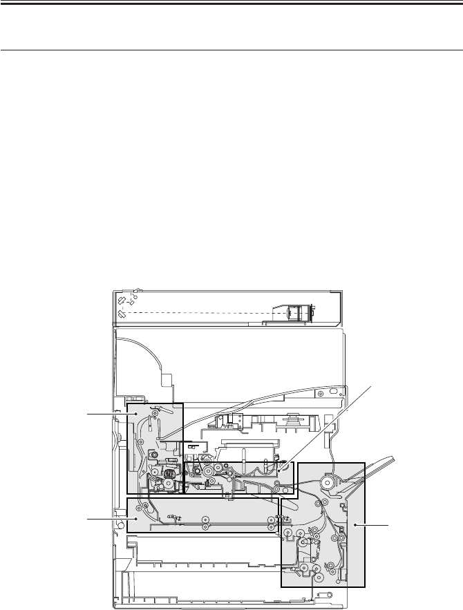
COPYRIGHT
©
2001 CANON INC. 2000 2000 2000 2000 CANON iR2200/iR2800/iR3300 REV.0 MAR. 2001
CHAPTER 4 TROUBLESHOOTING IMAGE FAULTS/MALFUNCTIONS
4-41 T
5 Troubleshooting Feeding Faults
5.1 Paper Jams
The jams that can occur inside the machine are grouped according to location:
[1] Pickup assembly
[2] Separation/feeding assembly
[3] Fixing/delivery assembly, duplex reversing assembly
[4] Duplex/feeding assembly
The descriptions that follow are also grouped according to the locations of jams; the loca-
tion and the nature of a specific jam may be checked in the machine’s service mode
(COPIER>DISPLAY>JAM).
F04-501-01
[1]
[4]
[3]
[2]

COPYRIGHT
©
2001 CANON INC. 2000 2000 2000 2000 CANON iR2200/iR2800/iR3300 REV.0 MAR. 2001
CHAPTER 4 TROUBLESHOOTING IMAGE FAULTS/MALFUNCTIONS
4-42 T
5.1.1 Pickup Assembly
1. General condition
Do the pickup roller and the feeding roller of the selected cassette, manual
feeder tray, and deck rotate during printing?
NO: See the descriptions for each (i.e., “fails to operate”).
2. Cassette
Is the cassette fitted correctly? Is the dial set correctly?
NO: Correct the cassette and the dial.
3. Cassette
Try a different cassette. Is the problem corrected?
YES: Check the faulty cassette.
4. Paper (moist)
Is the paper curled or wavy or in any way different?
YES: Replace the paper. Advise the user on the correct method of storing
paper.
5. Paper (non-recommended)
Try paper of a recommended type. Is the problem corrected?
YES: Advise the user to use recommended paper.
6. Paper guide plate
Is the paper guide plate deformed? Or, is there a piece of paper on it?
YES: Correct the deformation, and remove any piece of paper.
7. Main motor (M1), Vertical path clutch (CL1)
Does the main motor rotate?
YES: Check the roller and the vertical path clutch of the vertical path as-
sembly.
NO: Replace the main motor.

COPYRIGHT
©
2001 CANON INC. 2000 2000 2000 2000 CANON iR2200/iR2800/iR3300 REV.0 MAR. 2001
CHAPTER 4 TROUBLESHOOTING IMAGE FAULTS/MALFUNCTIONS
4-43 T
5.1.2 Separation/Feeding Assembly
1. Paper
Try paper of a recommended type. Is the problem corrected?
YES: Advise the user to use recommended paper.
2. Separation static eliminator
Is the separation static eliminator fully inserted?
NO: Insert it fully.
3. Pre-registration paper sensor lever, Registration paper sensor lever
Does the sensor lever in question move smoothly?
NO: Corrected it so that the lever moves correctly.
4. Pr-registration paper sensor (PS9), Registration paper sensor (PS10)
Find out the sensor detecting the jam in service mode
(COPIER>DISPLAY>JAM). Is there paper over the sensor?
NO: Check the wiring; if normal, replace the sensor.
5. Registration roller, Feeding unit (transfer charging roller)
Does the registration roller rotate?
NO: Check the registration motor (M9).
YES: Check to make sure that the feeder unit is securely locked in place;
if a fault is found, check the transfer charging roller assembly or
the feeder locking assembly.
5.1.3 Fixing/Delivery Assembly, Duplex Reversing Assembly
1. Fixing film
Is the fixing film deformed, damaged, or subjected to foreign matter?
YES:
1. For deformation or foreign matter, replace the film unit.
2. Remove foreign matter.
2. Fixing inlet guide plate
Is the fixing inlet guide plate soiled with toner or the like?
YES: Clean the guide.
3. Fixing/ feed sensor lever, No. 1 delivery paper sensor lever
Does the lever of the sensor in question move smoothly?
NO: Correct the lever so that it moves smoothly.

COPYRIGHT
©
2001 CANON INC. 2000 2000 2000 2000 CANON iR2200/iR2800/iR3300 REV.0 MAR. 2001
CHAPTER 4 TROUBLESHOOTING IMAGE FAULTS/MALFUNCTIONS
4-44 T
4. Fixing/feed sensor (PS13), No. 1 delivery sensor (PS15)
Find the sensor that detected the jam in service mode
(COPIER>DISPLAY>JAM). Is there paper over the sensor?
NO: Check the wiring; if normal, replace the sensor.
5. Delivery flapper (movement)
Doe the delivery flapper move smoothly? Further, does it move back to its
initial position by the work of the spring?
NO: Correct the mechanism so that the delivery flapper moves
smoothly.
6. Delivery flapper
Is the delivery flapper deformed or scratched ?
YES: Replace the flapper.
NO: Check the leading edge of the paper to see if there is a margin.
5.1.4 Duplex Feeding Assembly
1. Paper guide plate
Is there foreign matter around the paper guide? Or, is it deformed?
YES: Remove the foreign matter, and correct the deformation.
2. Duplex inlet paper sensor lever, Duplex output paper sensor lever
Does the lever of the sensor in question move smoothly?
NO: Correct the mechanisms so that the lever moves smoothly.
3. Duplex inlet paper sensor (PS17), Duplex outlet paper sensor (PS18)
Find the sensor that detected the jam in service mode:
COPIER>DISPLAY>JAM). Is the paper over the sensor?
NO: Check the wiring; if normal, replace the sensor.
4. Duplex motor (M6), roller (duplex assembly)
Select ‘4’ in the following service mode: COPIER>FUNCTION>PART-
CHK. When the OK key is pressed, does the duplex motor rotate?
YES: Check the roller of the duplex assembly.
NO: Check the wiring; if normal, replace the motor.

COPYRIGHT
©
2001 CANON INC. 2000 2000 2000 2000 CANON iR2200/iR2800/iR3300 REV.0 MAR. 2001
CHAPTER 4 TROUBLESHOOTING IMAGE FAULTS/MALFUNCTIONS
4-45 T
5.2 Faulty Feeding
5.2.1 Double Feeding
1. Pickup/feeding/separation roller releasing lever, Separation roller
When the releasing lever is pushed in toward the rear, is the pickup roller
released? Further, do the feeding roller and the separation roller come into
firm contact?
NO: The releasing lever (spring) is displaced or deformed. Correct or
replace it.
YES: Check the separation roller for deformation and wear. If a fault is
found, replace the separation roller.
5.2.2 Wrinkles
1. Pickup assembly
Turn off the power supply while paper is moving through the feeding as-
sembly. At this time, is the paper wrinkled? Or, is it moving askew?
YES:
[1] Check the pickup assembly.
[2] Check the guide in front of the registration roller.
[3] Check the registration roller.
2. Paper (moist)
Try new paper. Is the problem corrected?
YES: The paper may be moist. Advise the user on the correct method of
storing paper.
3. Paper (non-recommended type)
Try paper of a recommended type. Is the problem corrected?
YES: Advise the user to use paper of a recommended type.
4. Paper guide, fixing inlet drive solenoid (SL1)
Is the paper guide coated with toner or foreign matter?
YES: Clean the paper guide with solvent.
5. Fixing assembly, delivery feeding assembly
Is the fixing film, fixing lower roller, or cleaning roller faulty?
YES: Clean or replace it.
NO: Check the delivery feeding assembly for a fault.

COPYRIGHT
©
2001 CANON INC. 2000 2000 2000 2000 CANON iR2200/iR2800/iR3300 REV.0 MAR. 2001
CHAPTER 4 TROUBLESHOOTING IMAGE FAULTS/MALFUNCTIONS
4-46 T
6 Outline of Electrical Components
6.1 Introduction
The electrical components of the machine and its accessories are arranged as shown
herein, and they possess the functions discussed; the notations and the I/O addresses used
are based on those in the general circuit diagrams, enabling reference to the general circuit
diagrams for wiring and signal descriptions. (For the general circuit diagrams, see the Ap-
pendix.)
6.1.1 Guide to the List
The following notations are used to indicate the targets of connections:
DC-CON: DC controller PCB
R-CON: reader controller PCB
MN-CON: main controller PCB
FEED: pickup circuit PCB
MPWS: main power supply PCB
DECK-CON: side deck driver PCB
DECK-FEED: 2-Cassette Pedestal Pickup PCB
FAX-CON: G3 FAX control PCB

COPYRIGHT
©
2001 CANON INC. 2000 2000 2000 2000 CANON iR2200/iR2800/iR3300 REV.0 MAR. 2001
CHAPTER 4 TROUBLESHOOTING IMAGE FAULTS/MALFUNCTIONS
4-47 T
6.1.2 Checking the Photointerrupters
The photointerrupters are checked in service mode; go through the tables attached to the
lists of electrical components to find out the state* of a specific sensor, which may be any of
the following:
a. Paper Sensor
Move the sensor lever by hand to simulate the presence of paper; then, check the Service
Mode screen.
If it is difficult to check the Service Mode screen while moving the sensor lever, put paper
over the point of detection, and then check the Service Mode screen.
b. Open/Closed Sensor
Check the Service Mode screen while opening/closing the cover/unit in question.
c. Position Sensor, Presence/Absence Sensor
Move the unit in question by hand. Try removing and then mounting it. If the I/O level
changes in response to operation, the sensor may be assumed to be normal.
To check a photointerrupter found inside a unit which is detached in con-
junction with a drawer connector, be sure to check the Service Mode while
the unit in question is set.
*The state of a sensor refers to any of the following:
• For a paper sensor, the presence or the absence of paper.
• For an open/closed sensor, the state in which the cover/unit is closed.
• For a home position sensor or a set sensor, the item in question is in home position or
set in place.
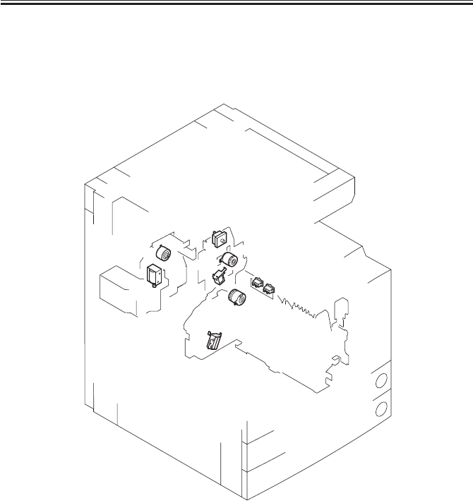
COPYRIGHT
©
2001 CANON INC. 2000 2000 2000 2000 CANON iR2200/iR2800/iR3300 REV.0 MAR. 2001
CHAPTER 4 TROUBLESHOOTING IMAGE FAULTS/MALFUNCTIONS
4-48 T
6.2 E201 (reader unit/printer unit)
6.2.1 Clutches
6.2.2 Solenoids, Switches
F04-602-01
SL5
SL6
CL3 CL2
SW3
SW1
SW2
CL1
SL1

COPYRIGHT
©
2001 CANON INC. 2000 2000 2000 2000 CANON iR2200/iR2800/iR3300 REV.0 MAR. 2001
CHAPTER 4 TROUBLESHOOTING IMAGE FAULTS/MALFUNCTIONS
4-49 T
6.2.1 Clutches
• Reader Unit
The reader unit does not have nay clutch.
• Printer Unit
Electrical signal (target)
Reference to general
I/O address Remarks
Name circuit diagram I/O indication
CL1 (DC-CON) A3-20-N P001-5
Vertical path clutch 0: ON, 1: OFF
CL2 (DC-CON) A3-18-N P001-6
Multifeeder clutch 0: ON, 1: OFF
CL3 (DC-CON) A3-20-J P001-7
Developing clutch 0: ON, 1: OFF
6.2.2 Solenoids, Switches
• Reader Unit
The reader unit does not have any solenoid or switch.
• Printer Unit
Electrical signal (target)
Reference to general
I/O address Remarks
Name circuit diagram I/O indication
SL1 (DC-CON) A3-20-N P002-0
Pickup DOWN solenoid 1: ON, 0: OFF
SL5 (DC-CON) A3-20-J P002-3
Multifeeder holding plate 1: ON, 0: OFF
releasing solenoid
SL6 (DC-CON) A3-20-J P002-4
Charging roller solenoid 1: ON, 0: OFF
SW1 (MPWS) A3-12-B
Main power switch
SW2 (MPWS) A3-12-B
Environment heater switch
SW3 (MPWS) A3-14-B P008-7
Front cover switch 0: open, 1: closed
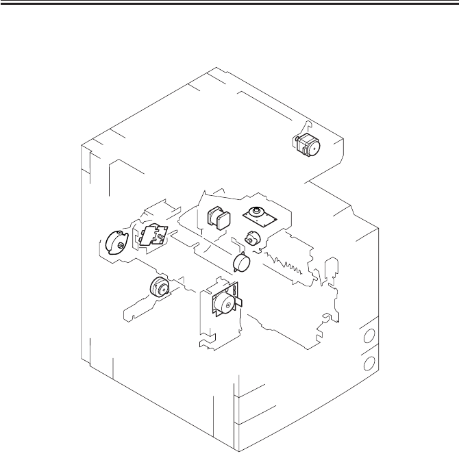
COPYRIGHT
©
2001 CANON INC. 2000 2000 2000 2000 CANON iR2200/iR2800/iR3300 REV.0 MAR. 2001
CHAPTER 4 TROUBLESHOOTING IMAGE FAULTS/MALFUNCTIONS
4-50 T
6.2.3 Motors (1/2)
F04-602-02
M1
M2
M3
M4
M5
M6
M9 M10
M400

COPYRIGHT
©
2001 CANON INC. 2000 2000 2000 2000 CANON iR2200/iR2800/iR3300 REV.0 MAR. 2001
CHAPTER 4 TROUBLESHOOTING IMAGE FAULTS/MALFUNCTIONS
4-51 T
6.2.3 Motors (1/2)
• Reader Unit
Electrical signal (target)
Reference to general
I/O address Remarks
Name circuit diagram I/O indication
M400 (R-CON) A3-18-G IO-P01-0
Scanner motor Clock signal
IO-P01-1
0: CW
IO-P01-2
0: drive enabled
IO-P01-4
1→0: return to origin
IO-P01-5, 6
Default
IO-P04-6
Analog
IO-P06-0
0: new current mode
• Printer Unit (1/2)
Electrical signal (target)
Reference to general
I/O address Remarks
Name circuit diagram I/O indication
M1 (DC-CON) A3-20-I P001-0
Main motor 0: ON, 1: OFF
P008-3
0: lock
M2 (FEED) A3-20-N P003-0 to 3
Pickup motor
M3 (DC-CON) A3-17-N P003-4 to 7
Horizontal registration
sensor shift motor
M4 (DC-CON) A3-15-J P001-3
Fixing motor 0: ON, 1: OFF
P001-4
1: ON, 0: OFF
P008-5
0: lock
M5 (DC-CON) A3-9-N P010-0 to 8
Delivery motor
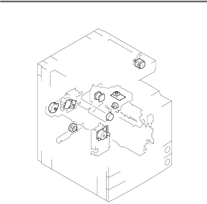
COPYRIGHT
©
2001 CANON INC. 2000 2000 2000 2000 CANON iR2200/iR2800/iR3300 REV.0 MAR. 2001
CHAPTER 4 TROUBLESHOOTING IMAGE FAULTS/MALFUNCTIONS
4-52 T
6.2.3 Motors (2/2)
F04-602-02
M1
M2
M3
M4
M5
M6
M9 M10
M400

COPYRIGHT
©
2001 CANON INC. 2000 2000 2000 2000 CANON iR2200/iR2800/iR3300 REV.0 MAR. 2001
CHAPTER 4 TROUBLESHOOTING IMAGE FAULTS/MALFUNCTIONS
4-53 T
6.2.3 Motors (2/2)
• Printer Unit (2/2)
Electrical signal (target)
Reference to general
I/O address Remarks
Name circuit diagram I/O indication
M6 (DC-CON) A3-8-N P005-0 to 7
Duplex motor
M9 (DC-CON) A3-14-M P002-5
Registration motor 1: OFF, 0: ON
P020-6, 7
M10 (DC-CON) A3-14-J P001-2
Laser scanner motor 0: lock
P008-3
0: lock
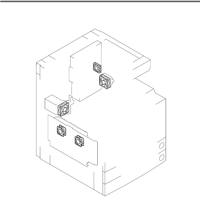
COPYRIGHT
©
2001 CANON INC. 2000 2000 2000 2000 CANON iR2200/iR2800/iR3300 REV.0 MAR. 2001
CHAPTER 4 TROUBLESHOOTING IMAGE FAULTS/MALFUNCTIONS
4-54 T
6.2.4 Fans
F04-602-03
FM4
FM5
FM1
FM2
FM3

COPYRIGHT
©
2001 CANON INC. 2000 2000 2000 2000 CANON iR2200/iR2800/iR3300 REV.0 MAR. 2001
CHAPTER 4 TROUBLESHOOTING IMAGE FAULTS/MALFUNCTIONS
4-55 T
6.2.4 Fans
• Reader Unit
The reader unit does not have any fan.
• Printer Unit
Electrical signal (target)
Reference to general
I/O address Remarks
Name circuit diagram I/O indication
FM1 (DC-CON) A3-18-N P004-0, 2
Developing fan 1: ON, 0: OFF
P009-4
0: ON
FM2 (DC-CON) A3-18-J P004-1, 3
Fixing fan 1: ON, 0: OFF
P009-5
0: ON
FM3 (MN-CON) A3-2-H
Electrical unit fan
FM4 (DC-CON) A3-7-I P005-6
Curl reducing fan 1 1: ON, 0: OFF
P009-6
0: ON
FM5 (DC-CON) A3-7-I P005-7
Curl reducing fan 2 1: ON, 0: OFF
P009-7
0: ON

COPYRIGHT
©
2001 CANON INC. 2000 2000 2000 2000 CANON iR2200/iR2800/iR3300 REV.0 MAR. 2001
CHAPTER 4 TROUBLESHOOTING IMAGE FAULTS/MALFUNCTIONS
4-56 T
6.2.5 Sensors (1/3)
F04-602-04
S5
S4
PS23
PS12
PS10
PS11
PS9
PS1-6 PS22
PS8
PS7
PS26
PS13
S2
PS15
PS17 PS18
PS16
PS400
PS401
S3
S1
VR1
SD1
BD

COPYRIGHT
©
2001 CANON INC. 2000 2000 2000 2000 CANON iR2200/iR2800/iR3300 REV.0 MAR. 2001
CHAPTER 4 TROUBLESHOOTING IMAGE FAULTS/MALFUNCTIONS
4-57 T
6.2.5 Sensors (1/3)
• Reader Unit
Electrical signal (target)
Reference to general
I/O address Remarks
Name circuit diagram I/O indication
PS400 (R-CON) A3-18-H IO-P06-4
Scanner home position sensor 1: HP
PS401 (R-CON) A3-17-H IO-P06-6
Copyboard cover sensor 0: open, 1: closed (copyboard/ADF)
SD1 (R-CON) A3-19-H IO-P03-5
Original sensor 0: present, 1: absent (paper)
IO-P04-4
0: ON, 1: OFF
• Printer Unit (1/3)
Electrical signal (target)
Reference to general
I/O address Remarks
Name circuit diagram I/O indication
BD (DC-CON) A3-13-K
BD sensor
PS1 (DC-CON) A3-19-N P013-5
Cassette 1 paper sensor 0: present, 1: absent (paper)
PS2 (DC-CON) A3-19-M P014-5
Cassette 2 paper sensor 0: present, 1: absent (paper)
PS3 (DC-CON) A3-20-M P013-6
Cassette 1 paper (paper)
level sensor 1 25% (bit6=0; bit7=1)
PS4 (DC-CON) A3-20-M P013-7 50% (bit6=1; bit7=1)
Cassette 1 paper 100% (bit6=0; bit7=0)
level sensor 2
PS5 (DC-CON) A3-20-M P014-6
Cassette 2 paper (paper)
level sensor 1 25% (bit6=0; bit7=1)
PS6 (DC-CON) A3-20-M P014-7 50% (bit6=1; bit7=1)
Cassette 2 paper 100% (bit6=0; bit7=0)
level sensor 2
PS7 (DC-CON) A3-20-M P015-0
Cassette 1 re-try 1: present, 0: absent (paper)
paper sensor

COPYRIGHT
©
2001 CANON INC. 2000 2000 2000 2000 CANON iR2200/iR2800/iR3300 REV.0 MAR. 2001
CHAPTER 4 TROUBLESHOOTING IMAGE FAULTS/MALFUNCTIONS
4-58 T
6.2.5 Sensors (2/3)
F04-602-04
S5
S4
PS23
PS12
PS10
PS11
PS9
PS1-6 PS22
PS8
PS7
PS26
PS13
S2
PS15
PS17 PS18
PS16
PS400
PS401
S3
S1
VR1
SD1
BD

COPYRIGHT
©
2001 CANON INC. 2000 2000 2000 2000 CANON iR2200/iR2800/iR3300 REV.0 MAR. 2001
CHAPTER 4 TROUBLESHOOTING IMAGE FAULTS/MALFUNCTIONS
4-59 T
6.2.5 Sensors (2/3)
• Printer Unit (2/3)
Electrical signal (target)
Reference to general
I/O address Remarks
Name circuit diagram I/O indication
PS8 (DC-CON) A3-20-M P015-1
Cassette 2 re-try paper sensor 1: present, 0: absent (paper)
PS9 (DC-CON) A3-16-N P015-2
Pre-registration paper sensor 1: present, 0: absent (paper)
PS10 (DC-CON) A3-16-N P015-3
Registration paper sensor 1: present, 0: absent (paper)
PS11 (DC-CON) A3-16-N P015-4
Horizontal registration 0: present,1: absent (paper)
paper sensor
PS12 (DC-CON) A3-16-I P025-7
Image leading edge sensor 1: present, 0: absent (paper)
PS13 (DC-CON) A3-8-J P015-5
Fixing/feeding sensor 0: present,1: absent (paper)
PS15 (DC-CON) A3-8-N P015-6
No. 1 delivery sensor 1: present, 0: absent (paper)
PS16 (DC-CON) A3-9-N P015-7
No. 1 delivery full sensor 1: present, 0: absent (paper)
PS17 (DC-CON) A3-7-N P016-0
Duplex unit inlet paper sensor 0: present,1: absent (paper)
PS18 (DC-CON) A3-7-N P016-1
Duplex unit outlet paper sensor 0: present,1: absent (paper)
PS22 (DC-CON) A3-15-N P016-5
Multifeeder paper sensor 0: present,1: absent (paper)
PS23 (DC-CON) A3-15-N P016-6
Right cover open/closed sensor 1: open, 0: closed
PS26 (DC-CON) A3-8-J P021-0
Fixing film sensor
S1 (DC-CON) A3-18-N P008-0
Toner sensor 1: present, 0: absent (toner)
S2 (DC-CON) A3-6-I P008-2
Waste toner case full sensor 1: full (waste toner)
S3 (DC-CON) A3-17-N P023-4, P33 (humidity)
Environment sensor A/D
P023-5, P34 (room temperature)
A/D
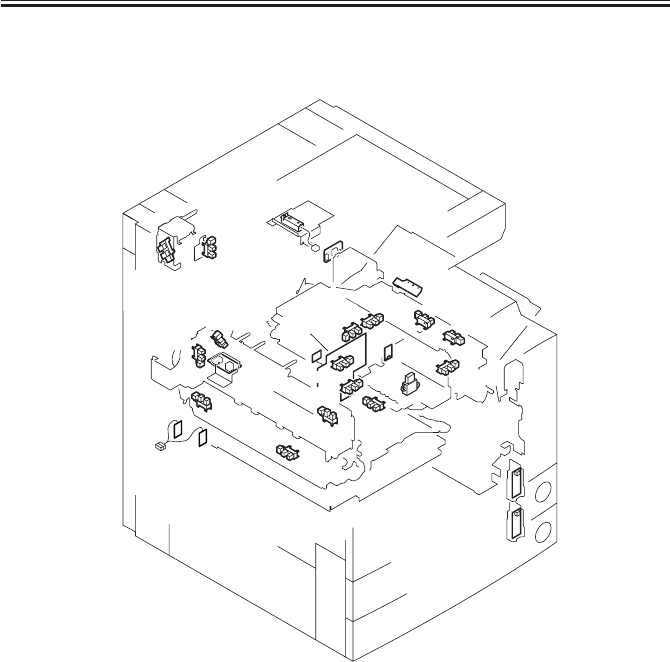
COPYRIGHT
©
2001 CANON INC. 2000 2000 2000 2000 CANON iR2200/iR2800/iR3300 REV.0 MAR. 2001
CHAPTER 4 TROUBLESHOOTING IMAGE FAULTS/MALFUNCTIONS
4-60 T
6.2.5 Sensors (3/3)
F04-602-04
S5
S4
PS23
PS12
PS10
PS11
PS9
PS1-6 PS22
PS8
PS7
PS26
PS13
S2
PS15
PS17 PS18
PS16
PS400
PS401
S3
S1
VR1
SD1
BD

COPYRIGHT
©
2001 CANON INC. 2000 2000 2000 2000 CANON iR2200/iR2800/iR3300 REV.0 MAR. 2001
CHAPTER 4 TROUBLESHOOTING IMAGE FAULTS/MALFUNCTIONS
4-61 T
6.2.5 Sensors (3/3)
Electrical signal (target)
Reference to general
I/O address Remarks
Name circuit diagram I/O indication
S4 (DC-CON) A3-17-J P013-0 to 4
Cassette 1 size sensor
S5 (DC-CON) A3-16-J P014-0 to 4
Cassette 2 size sensor
VR1 (DC-CON) A3-18-M P023-2, P31
Multifeeder paper width sensor A/D
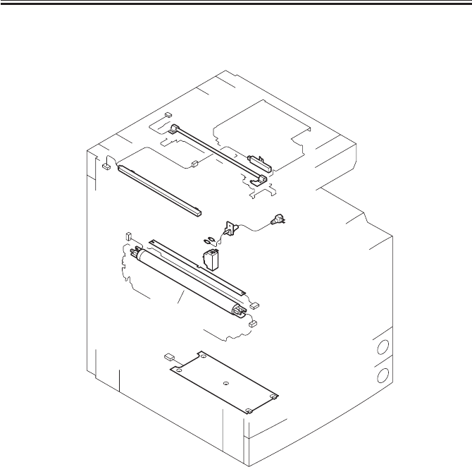
COPYRIGHT
©
2001 CANON INC. 2000 2000 2000 2000 CANON iR2200/iR2800/iR3300 REV.0 MAR. 2001
CHAPTER 4 TROUBLESHOOTING IMAGE FAULTS/MALFUNCTIONS
4-62 T
6.2.6 Lamps, Heaters, and Others
F04-602-05
LAMP1
H5
H4
CB1
PLG1
LAMP2
H3
H1,H2,
TP1,
TH1,TH2

COPYRIGHT
©
2001 CANON INC. 2000 2000 2000 2000 CANON iR2200/iR2800/iR3300 REV.0 MAR. 2001
CHAPTER 4 TROUBLESHOOTING IMAGE FAULTS/MALFUNCTIONS
4-63 T
6.2.6 Lamps, Heaters, and Others
• Reader Unit
Electrical signal (target)
Reference to general
I/O address Remarks
Name circuit diagram I/O indication
H4 (MPWS) A3-9-A
Standard with 100V model
Mirror heater
(accessory for 200V model)
H5 (MPWS) A3-9-A
Standard with 100V model
Lens heater
(accessory for 200V model)
LAMP1 (R-CON) A3-17-H
Scanning lanp
• Printer Unit
Electrical signal (target)
Reference to general
I/O address Remarks
Name circuit diagram I/O indication
CB1 (MPWS) A3-14-A
Leakage breaker
H1 (MPWS) A3-9-C
Fixing main heater
H2 (MPWS) A3-9-B
Fixing sub heater
H3 (MPWS) A3-9-B (accessory)
Cassette heater
LAMP2 (DC-CON) A3-14-J P001-1
Pre-exposure lamp 1: ON, 0: OFF
PLG1 (DC-CON) A3-14-A
Power supply cord
TH1 (MPWS) A3-12-J P023-0, P29
Main thermistor A/D
TH2 (DC-CON) A3-12-J P023-1, P30
Sub thermistor A/D
TP1 (DC-CON) A3-9-B
Thermal switch
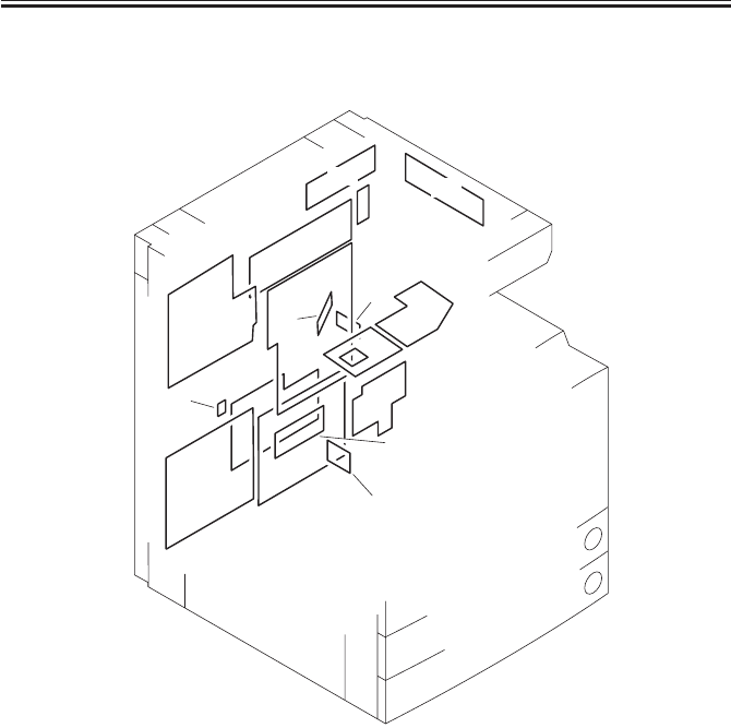
COPYRIGHT
©
2001 CANON INC. 2000 2000 2000 2000 CANON iR2200/iR2800/iR3300 REV.0 MAR. 2001
CHAPTER 4 TROUBLESHOOTING IMAGE FAULTS/MALFUNCTIONS
4-64 T
6.2.7 PCBs
F04-602-06
[3]
[11]
[9]
[9]
[5]
[13]
[2]
[7]
[6]
[10]
[10]
[8]
[1]
[12]
[10]
[4]
[14]

COPYRIGHT
©
2001 CANON INC. 2000 2000 2000 2000 CANON iR2200/iR2800/iR3300 REV.0 MAR. 2001
CHAPTER 4 TROUBLESHOOTING IMAGE FAULTS/MALFUNCTIONS
4-65 T
6.2.7 PCBs
• Reader Unit
Ref. Description Remarks
Name
[12] Controls the reader unit/ADF.
Reader controller PCB
[13] Drives the CCD.
CCD PCB
[14] Controls the scanning lamp.
Inverter PCB
• Printer Unit
Ref. Description Remarks
Name
[1] Controls the generation of
Composite power supply PCB high voltage.
[2] Controls the supply of DC .
Main power supply PCB power
[3] Controls the main power
Switch PCB switch/heater.
[4] Controls the printer unit.
DC controller PCB
[5] Controls the pickup assembly.
Pickup PCB
[6] Controls laser drive.
Laser driver PCB
[7] Controls the supply of power
Accessories power supply PCB to the finisher/paper deck.
[8] Detects temperature of the drum.
Drum sensor PCB
[9] Controls keys and LEDs.
Control panel PCB
[10] Controls digital image Includes counter PCB,
Main controller PCB processing/system. soft IDPCB, Centronics PCB.
[11] Controls the DC-DC converter. 200V model only.
Thermistor separation power
supply PCB
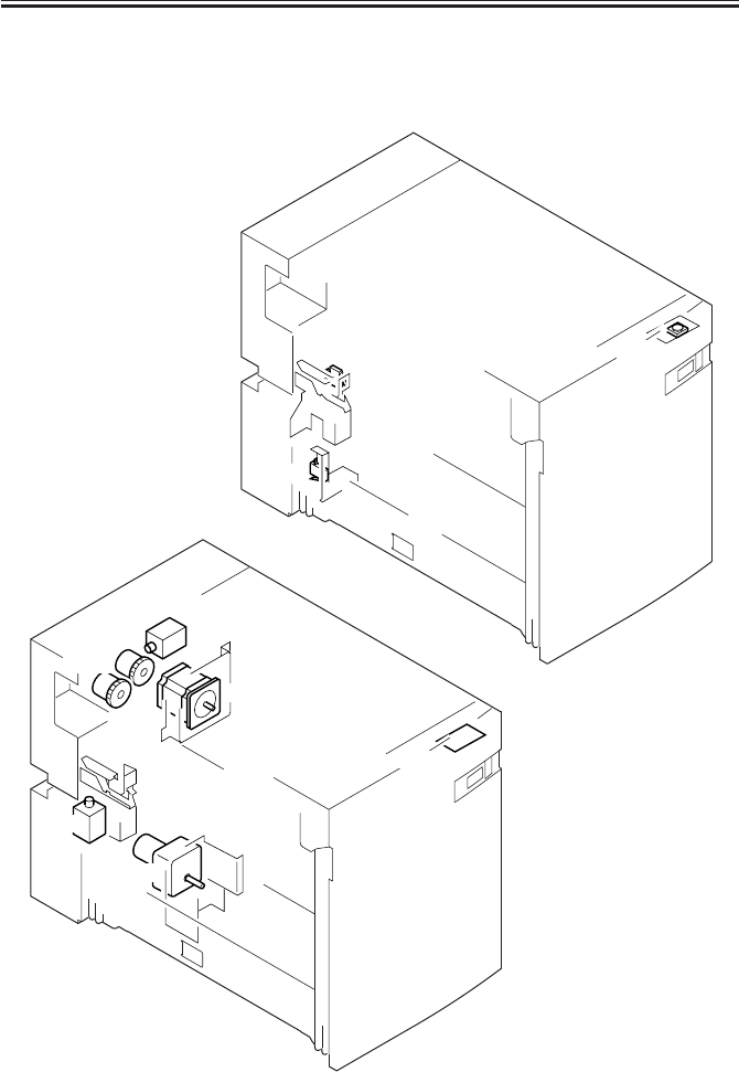
COPYRIGHT
©
2001 CANON INC. 2000 2000 2000 2000 CANON iR2200/iR2800/iR3300 REV.0 MAR. 2001
CHAPTER 4 TROUBLESHOOTING IMAGE FAULTS/MALFUNCTIONS
4-66 T
6.3 Side Paper Deck-L1
6.3.1 Clutches
6.3.2 Solenoids, and Switches
6.3.3 Motors
F04-603-01
M1D
SL2D
M2D
SL1D
LED100D
CL2D
CL1D
SW2D
SW1D SW100D

COPYRIGHT
©
2001 CANON INC. 2000 2000 2000 2000 CANON iR2200/iR2800/iR3300 REV.0 MAR. 2001
CHAPTER 4 TROUBLESHOOTING IMAGE FAULTS/MALFUNCTIONS
4-67 T
6.3.1 Clutches
Electrical signal (target)
Reference to general
I/O address Remarks
Name circuit diagram I/O indication
CL1D (DECK-CON) A5-9-A
Deck feeding clutch 0: ON, 1: OFF
CL2D (DECK-CON) A5-8-A
Deck pickup clutch 0: ON, 1: OFF
6.3.2 Solenoids and Switches
Electrical signal (target)
Reference to general
I/O address Remarks
Name circuit diagram I/O indication
SL1D (DECK-CON) A5-10-A
Deck pickup roller 0: ON, 1: OFF
releasing solenoid
SL2D (DECK-CON) A5-4-B
Deck open solenoid 0: ON, 1: OFF
SW1D (DECK-CON) A5-3-H
Deck open detecting switch
SW2D (DECK-CON) A5-5-B
Deck lifter lower limit
detecting switch
SW100D (DECK-CON) A5-13-A
Deck open switch
LED100D (DECK-CON) A5-13-A
Deck open indication
6.3.3 Motors
Electrical signal (target)
Reference to general
I/O address Remarks
Name circuit diagram I/O indication
M1D (DECK-CON) A5-5-H
Deck main motor
M2D (DECK-CON) A5-5-B
Deck lifter motor
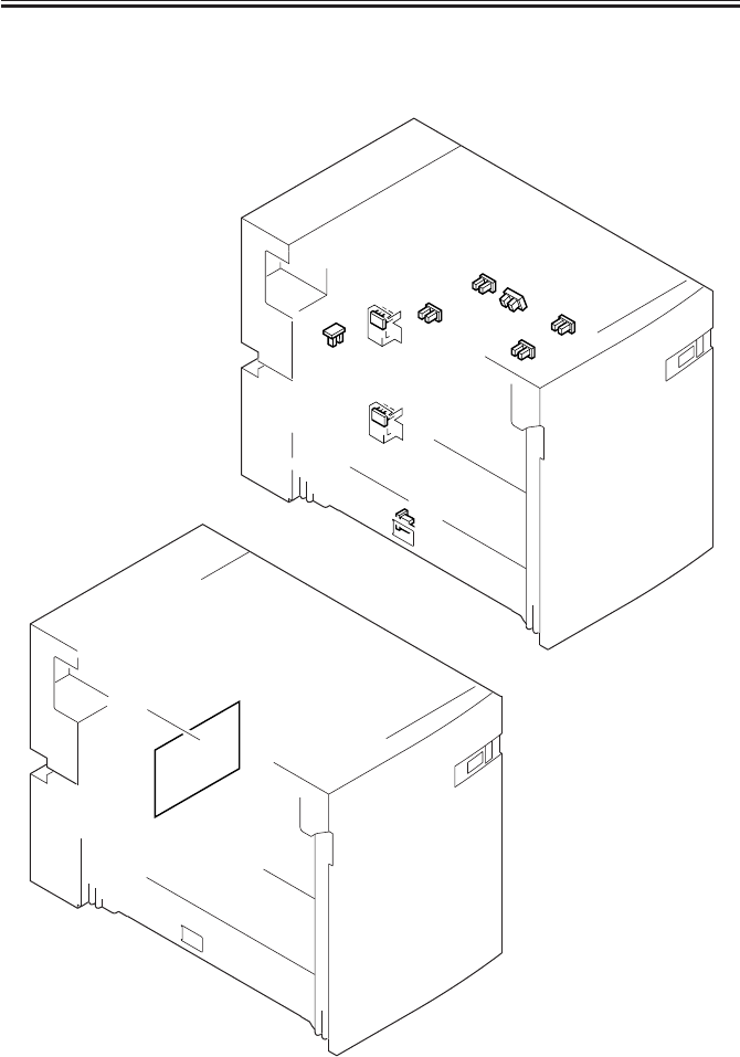
COPYRIGHT
©
2001 CANON INC. 2000 2000 2000 2000 CANON iR2200/iR2800/iR3300 REV.0 MAR. 2001
CHAPTER 4 TROUBLESHOOTING IMAGE FAULTS/MALFUNCTIONS
4-68 T
6.3.4 Sensors
6.3.5 PCBs
F04-603-02
[1]
PS6D
PS5D
PS1D
PS4D
PS2D
PS3D
PS8D
PS9D
PS7D

COPYRIGHT
©
2001 CANON INC. 2000 2000 2000 2000 CANON iR2200/iR2800/iR3300 REV.0 MAR. 2001
CHAPTER 4 TROUBLESHOOTING IMAGE FAULTS/MALFUNCTIONS
4-69 T
6.3.4 Sensors
Electrical signal (target)
Reference to general
I/O address Remarks
Name circuit diagram I/O indication
PS1D (DECK-CON) A5-8-A
Deck pickup sensor
PS2D (DECK-CON) A5-12-A
Deck paper absent sensor
PS3D (DECK-CON) A5-11-A
Deck lifter upper limit sensor
PS4D (DECK-CON) A5-11-A
Deck lifter position sensor
PS5D (DECK-CON) A5-3-C
Deck set sensor
PS6D (DECK-CON) A5-10-A
Deck feed sensor
PS7D (DECK-CON) A5-6-C
Deck paper level sensor
PS8D (DECK-CON) A5-7-C
Deck paper supply
position sensor
PS9D (DECK-CON) A5-3-C
Deck open sensor
6.3.5 PCBs
Ref. Description Remarks
Name
[1]
Side deck driver PCB
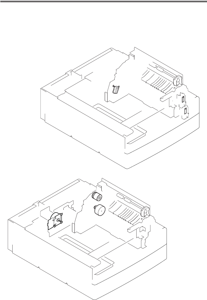
COPYRIGHT
©
2001 CANON INC. 2000 2000 2000 2000 CANON iR2200/iR2800/iR3300 REV.0 MAR. 2001
CHAPTER 4 TROUBLESHOOTING IMAGE FAULTS/MALFUNCTIONS
4-70 T
6.4 2-Cassette Feeding Unit-W1
6.4.1 Clutches
6.4.2 Solenoids and Switches
6.4.3 Motors
F04-604-01
S1C
S2C
M1C M2C
SL1C
CL1C

COPYRIGHT
©
2001 CANON INC. 2000 2000 2000 2000 CANON iR2200/iR2800/iR3300 REV.0 MAR. 2001
CHAPTER 4 TROUBLESHOOTING IMAGE FAULTS/MALFUNCTIONS
4-71 T
6.4.1 Clutches
Electrical signal (target)
Reference to general
I/O address Remarks
Name circuit diagram I/O indication
CL1C (PEDE-FEED) A6-11-F
Vertical path roller clutch 0: ON, 1: OFF
6.4.2 Solenoids and Switches
Electrical signal (target)
Reference to general
I/O address Remarks
Name circuit diagram I/O indication
SL1C (PEDE-FEED) A6-11-F
Pickup roller DOWN solenoid 0: ON, 1: OFF
S1C (PEDE-CON) A6-7-A
Cassette 3 size detecting switch
S2C (PEDE-CON) A6-6-A
Cassette 4 size detecting switch
6.4.3 Motors
Electrical signal (target)
Reference to general
I/O address Remarks
Name circuit diagram I/O indication
M1C (PEDE-CON) A6-2-E
Pedestal main motor
M2C (PEDE-FEED) A6-11-G
Cassette pickup motor

COPYRIGHT
©
2001 CANON INC. 2000 2000 2000 2000 CANON iR2200/iR2800/iR3300 REV.0 MAR. 2001
CHAPTER 4 TROUBLESHOOTING IMAGE FAULTS/MALFUNCTIONS
4-72 T
6.4.4 Sensors
6.4.5 PCBs
F04-604-02
[2]
[1]
PS1C
PS2C
PS3C
Q1603~1609

COPYRIGHT
©
2001 CANON INC. 2000 2000 2000 2000 CANON iR2200/iR2800/iR3300 REV.0 MAR. 2001
CHAPTER 4 TROUBLESHOOTING IMAGE FAULTS/MALFUNCTIONS
4-73 T
6.4.4 Sensors
Electrical signal (target)
Reference to general
I/O address Remarks
Name circuit diagram I/O indication
PS1C (PEDE-CON) A6-6-H
Right cover open/closed sensor
PS2C (PEDE-FEED) A6-11-D
Cassette 3 re-try paper sensor
PS3C (PEDE-FEED) A6-11-C
Cassette 4 re-try paper sensor
Q1603 (PEDE-CON) A6-9-E
Vertical path paper sensor
Q1604 (PEDE-FEED) A6-12-E
Cassette 3 paper sensor
Q1605 (PEDE-CON) A6-9-E
Cassette 4 paper sensor
Q1606 (PEDE-CON) A6-9-E
Cassette 3 paper level sensor 0
Q1607 (PEDE-CON) A6-9-E
Cassette 3 paper level sensor 1
Q1608 (PEDE-CON) A6-9-E
Cassette 4 paper level sensor 0
Q1609 (PEDE-CON) A6-9-E
Cassette 4 paper level sensor 1
6.4.5 PCBs
Ref. Description Remarks
Name
[1] Controls the pickup assembly.
2-cassette pedestal pickup PCB
[2] Controls the paper deck.
Pedestal controller PCB
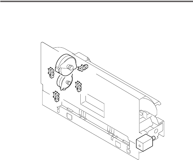
COPYRIGHT
©
2001 CANON INC. 2000 2000 2000 2000 CANON iR2200/iR2800/iR3300 REV.0 MAR. 2001
CHAPTER 4 TROUBLESHOOTING IMAGE FAULTS/MALFUNCTIONS
4-74 T
6.5 Inner 2-Way Tray-A1
6.5.1 Solenoids
6.5.2 Motors
6.5.3 Sensor
F04-605-01
PS24B
PS20B
PS19B
PS21B
M8B
M7B
SL3B

COPYRIGHT
©
2001 CANON INC. 2000 2000 2000 2000 CANON iR2200/iR2800/iR3300 REV.0 MAR. 2001
CHAPTER 4 TROUBLESHOOTING IMAGE FAULTS/MALFUNCTIONS
4-75 T
6.5.1 Solenoids
Electrical signal (target)
Reference to general
I/O address Remarks
Name circuit diagram I/O indication
SL3B (DC-CON) A7-2-K
2-way delivery solenoid 0: ON, 1: OFF
6.5.2 motors
Electrical signal (target)
Reference to general
I/O address Remarks
Name circuit diagram I/O indication
M7B (DC-CON) A7-10-H P011-0 to 7
2-way delivery inlet motor
M8B (DC-CON) A7-6-H P004-4 to 8
2-way deliver outlet motorr
P006-7
1: 70%, 0: 100%
6.5.3 Sensors
Electrical signal (target)
Reference to general
I/O address Remarks
Name circuit diagram I/O indication
PS19B (DC-CON) A7-3-G P016-2
No. 2 delivery sensor 1: present, 0: absent (paper)
PS20B (DC-CON) A7-8-G P016-3
No. 2 delivery full sensor 1: present, 0: absent (paper)
PS21B (DC-CON) A7-8-G P016-4
No. 3 delivery sensor 1: present, 0: absent (paper)
PS24B (DC-CON) A7-4-G P016-7
2-way delivery open/closed 1: open, 0: closed
sensor
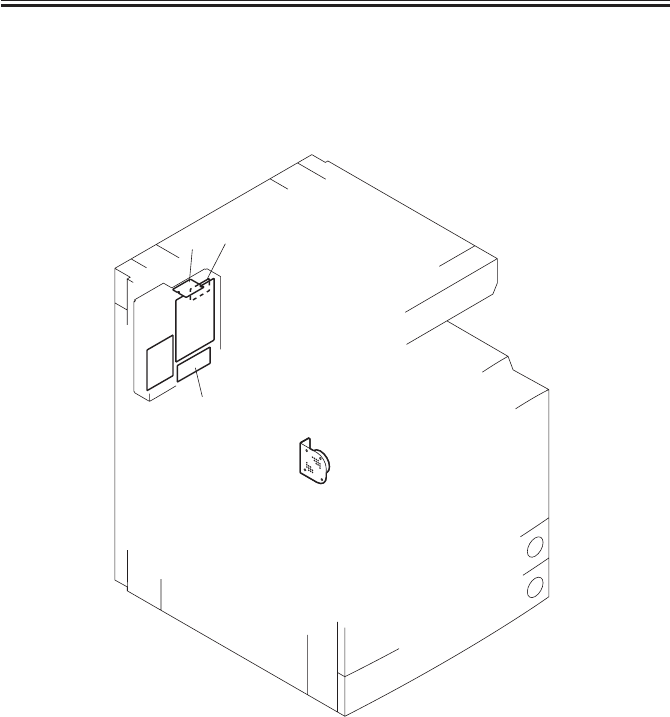
COPYRIGHT
©
2001 CANON INC. 2000 2000 2000 2000 CANON iR2200/iR2800/iR3300 REV.0 MAR. 2001
CHAPTER 4 TROUBLESHOOTING IMAGE FAULTS/MALFUNCTIONS
4-76 T
6.6 Super G3 FAX Board-J1
6.6.1 Others
6.6.2 PCBs
F04-606-01
SP1
[1]
[2]
[3] [4]
[5]

COPYRIGHT
©
2001 CANON INC. 2000 2000 2000 2000 CANON iR2200/iR2800/iR3300 REV.0 MAR. 2001
CHAPTER 4 TROUBLESHOOTING IMAGE FAULTS/MALFUNCTIONS
4-77 T
6.6.1 Others
Electrical signal (target)
Reference to general
I/O address Remarks
Name circuit diagram I/O indication
SP1 (FAX-CON)
A3-1-E
Speaker
6.6.2 PCBs
Ref. Description Remarks
Name
[1] Controls the fax system.
G3 FAX control PCB
[2] Serves as an interface between 100V and 120V models use
NCU PCB telephone line and fax system. different interfaces.
[3] Connects a modular cable. 100V and 120V models use
G3 modular PCB different interfaces.
[4] Stores firmware for the fax 16M bit
DIMM system.
[5] Generates a pseudo CI signal. 100V
Pseudo CI PCB
[6] Detects off-hook state of the 120V
Off-hook detection PCB telephone

COPYRIGHT
©
2001 CANON INC. 2000 2000 2000 2000 CANON iR2200/iR2800/iR3300 REV.0 MAR. 2001
CHAPTER 4 TROUBLESHOOTING IMAGE FAULTS/MALFUNCTIONS
4-78 T
6.7 Variable Resistors (VR), Light-Emitting Diodes, and Check
Pins by PCB
Of the variable resistors, light-emitting diodes, and switches used in the machine, those
needed for service work in the field are discussed:
1. Some LEDs emit dim light when they are off because of leakage cur-
rent; this is a normal condition, and must be kept in mind.
2. VRs that may be used in the field:
VRs that must not be used in the field:
Do not touch those VRs and check pins not discussed herein; they are for
exclusive use in the factory, and require high accuracy and special instru-
ments.
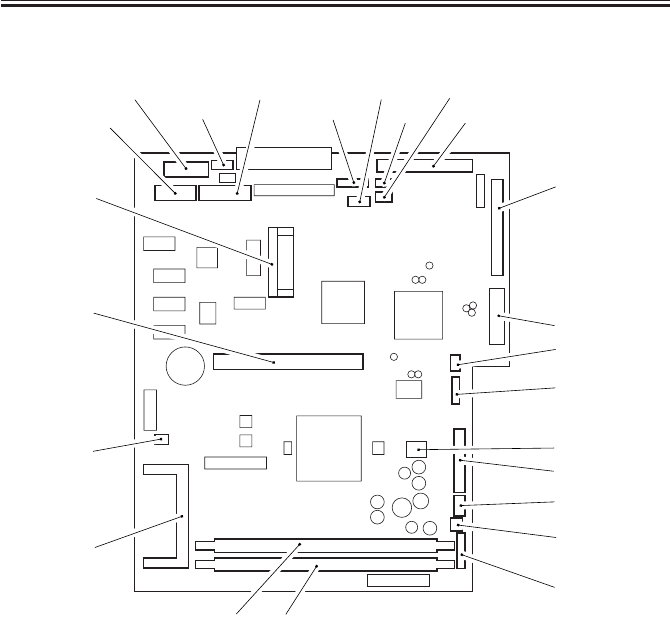
COPYRIGHT
©
2001 CANON INC. 2000 2000 2000 2000 CANON iR2200/iR2800/iR3300 REV.0 MAR. 2001
CHAPTER 4 TROUBLESHOOTING IMAGE FAULTS/MALFUNCTIONS
4-79 T
6.7.1 Main Controller PCB
F04-607-01
The DIP switch (SW1002) is designed for adjustments at the factory, and is not normally
used in the field.
<When Replacing the PCB>
a. Transfer the following from the old to new PCB:
• shorting connector of J1060
• BOOT ROM of J1010
• SDRAM
• counter memory PCB
b. Protect the back-up data as follows:
1) Back up all data using the Service Support Tool.
2) Replace the main controller.
3) While holding down the keys ‘2’ and ‘8’ of the control panel, turn on the main power (to
start download mode). You will not be able to perform the following if you start up in
the usual way, since the Box text file data and control data on the hard disk will be ini-
tialized.
4) Download all data using the Service Support Tool.
J1019 J1044
J1029
J1024 J1061 J1014
J1015
J1005
J1013
J1011
J1028
J1010
J1003 J1004
J1059
J1006
SW1002
J1020
J1058
J1027
J1001
J1012 J1022 J1060
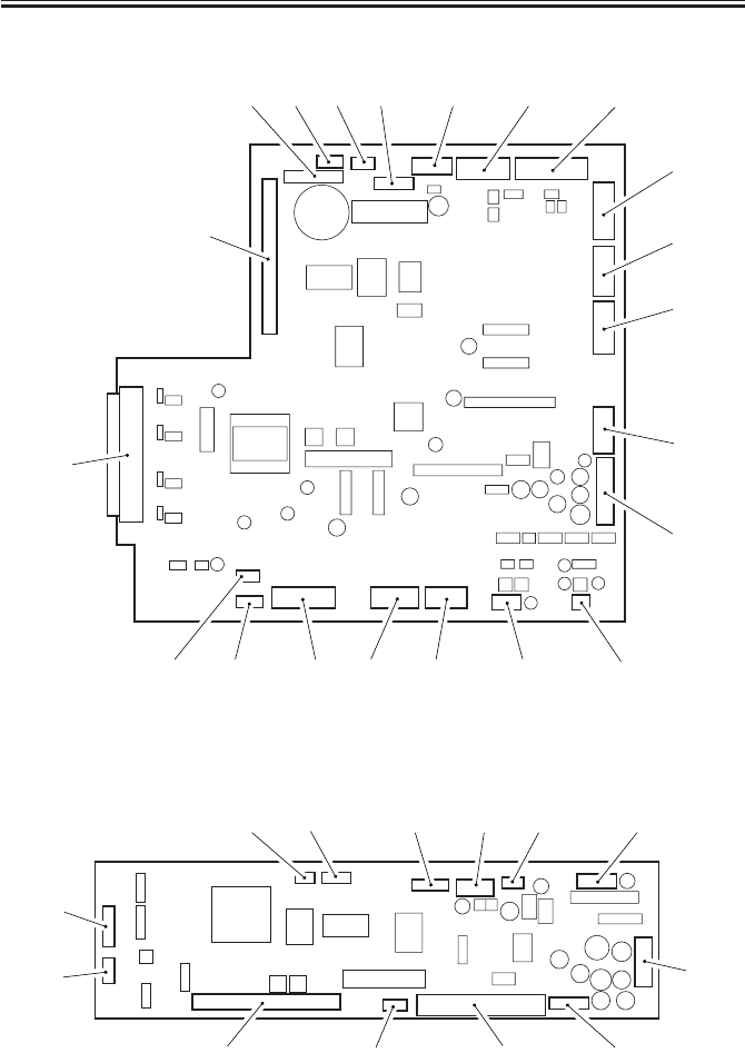
COPYRIGHT
©
2001 CANON INC. 2000 2000 2000 2000 CANON iR2200/iR2800/iR3300 REV.0 MAR. 2001
CHAPTER 4 TROUBLESHOOTING IMAGE FAULTS/MALFUNCTIONS
4-80 T
6.7.2 DC Controller PCB
F04-607-02
6.7.3 Reader Controller PCB
F04-607-03
J330
J322
J333 J319 J331 J309 J304 J302
J301
J315
J313
J308
J300
J332J320J311J314J312J310J307
J316
J400
J412J409J410J413
J408
J407
J406 J405 J404 J403 J402 J401

COPYRIGHT
©
2001 CANON INC. 2000 2000 2000 2000 CANON iR2200/iR2800/iR3300 REV.0 MAR. 2001
CHAPTER 4 TROUBLESHOOTING IMAGE FAULTS/MALFUNCTIONS
4-81 T
6.7.4 Composite Power Supply PCB
When replacing the PCB, be sure to enter the settings indicated on the service label [1] in
service mode.
F04-607-04
6.7.5 Fixing Film Sensor PCB
F04-607-05
[1]
J3146
VR1

COPYRIGHT
©
2001 CANON INC. 2000 2000 2000 2000 CANON iR2200/iR2800/iR3300 REV.0 MAR. 2001
CHAPTER 5
SERVICE MODE
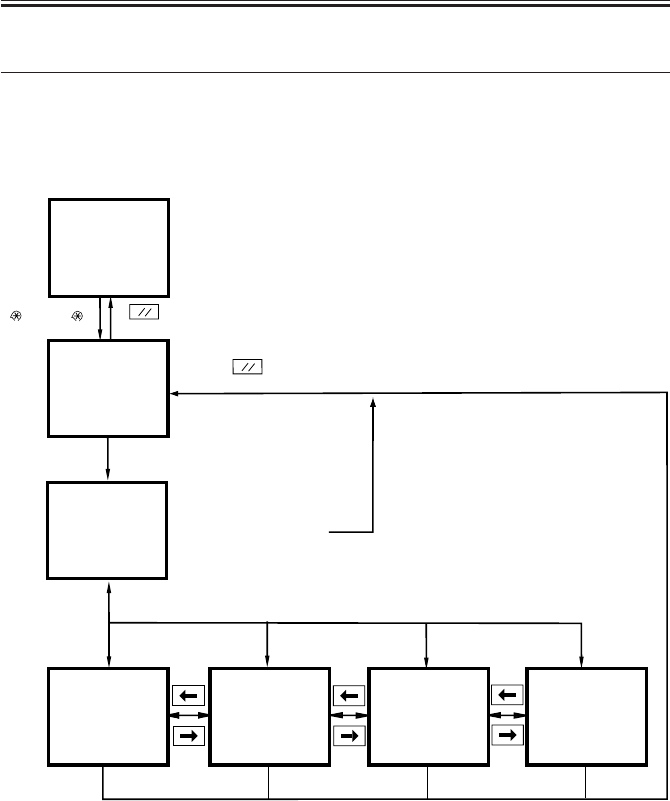
COPYRIGHT
©
2001 CANON INC. 2000 2000 2000 2000 CANON iR2200/iR2800/iR3300 REV.0 MAR. 2001
CHAPTER 5 SERVICE MODE
5-1 T
1 Outline of Service Mode
1.1 Outline
The service mode screens are organized in three levels: Initial screen, Level 1/Level 2
Item screen, Level 3 Item screen.
F05-101-01
Initial screen
Level 1/Level 2
Item screen
Level 3 Item
screen Level 3 Item
screen
Level 3 Item
screen
User screen
From Level 1/Level 2
item screen
Reset key
Previous/Next screen
Previous/Next page
Previous/Next page
( )(2,8)( )
Reset key
Select a Level 1 item from the top of the screen.
Select a Level 2 item from the list.
Level 3 Item
screen
Select an item.
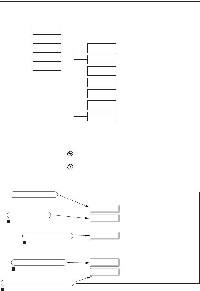
COPYRIGHT
©
2001 CANON INC. 2000 2000 2000 2000 CANON iR2200/iR2800/iR3300 REV.0 MAR. 2001
CHAPTER 5 SERVICE MODE
5-2 T
The machines’ service mode consists of the following seven types:
F05-101-02
1.2 Starting Service Mode and Making Selections
1) Press the User Mode key ‘ ’ .
2) Press ‘2’ and ‘8’ on the keypad at the same time.
3) Press the User Mode key ‘ ’ on the control panel.
In response, the following Initial screen will appear:
F05-102-01
COPIER
FEEDER
SORTER
FAX
BOARD
DISPLAY
I/O
ADJUST
FUNCTION
OPTION
TEST
COUNTER
control display mode
I/O display mode
adjustment mode
operation/check mode
settings mode
test print mode
counter mode
FAX
COPIER
FEEDER
SORTER
FAX
BOARD
if installed.
if installed.
if installed.
Copier service mode
ADF service mode
Finisher service mode
if installed.
Fax board service mode
Accessories board service mode
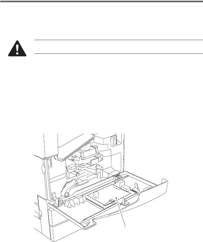
COPYRIGHT
©
2001 CANON INC. 2000 2000 2000 2000 CANON iR2200/iR2800/iR3300 REV.0 MAR. 2001
CHAPTER 5 SERVICE MODE
5-3 T
1.3 Ending Service Mode
• Press the Reset key once to return to the Service Mode Initial screen (F05-101-03).
• Press the Reset key twice to end service mode and return to the User screen (standard).
If you have used service mode (ADJUST, FUNCTION, OPTION), be sure
to turn off and then on the main power switch after ending service mode.
1.4 Backing Up Service Mode
At the factory, each machine is adjusted, and its adjustment settings are recorded on the
service label [1] (inside the service book case behind the front cover).
If you have cleared the RAM and replaed the PCB, the settings under ADJUST and OP-
TION will all return to the factory settings. Be sure to enter the settings indicated on the ser-
vice label. You can print out the settings stored in the machine in service mode:
COPIER>FUNCTION>MISC-P>P-PRINT. In addition, you can obtain a new service label
using service mode: COPIER>FUNCTION>MISC-P>LBL-PRINT.
F05-104-01
[1]
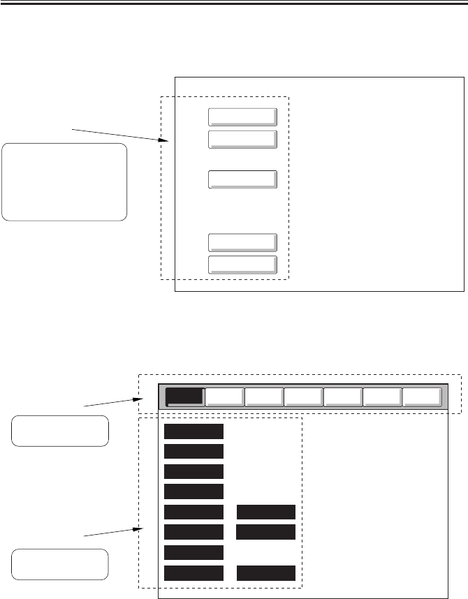
COPYRIGHT
©
2001 CANON INC. 2000 2000 2000 2000 CANON iR2200/iR2800/iR3300 REV.0 MAR. 2001
CHAPTER 5 SERVICE MODE
5-4 T
1.5 Using Service Mode
1.5.1 Initial Screen
F05-105-01
1.5.2 Level 1/Level 2 Item Screen
F05-105-02
FAX
COPIER
FEEDER
SORTER
FAX
BOARD
Initial settings
Touch an item to select.
(FEEDER, SORTER,
FAX, and BOARD are
indicated only when
installed.)
Counter
Test
Option
Function
Adjust
I/O
Display
VERSION
USER
ACC-STS
ANALOG
CST-STS
JAM MISC
ERR
HV-STS
SENSOR
ALARM-2
Level 1 items
Touch an item to
select.
Level 2 items
Touch an item to
select.
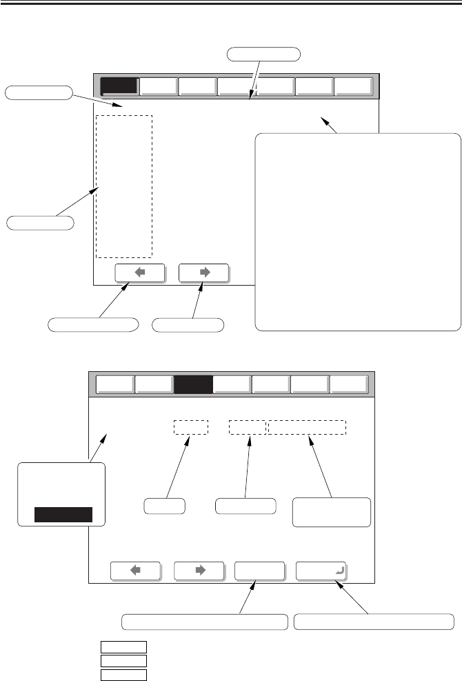
COPYRIGHT
©
2001 CANON INC. 2000 2000 2000 2000 CANON iR2200/iR2800/iR3300 REV.0 MAR. 2001
CHAPTER 5 SERVICE MODE
5-5 T
1.5.3 Level 3 Item Screen
F05-105-03
F05-105-04
Counter
Test
Option
Function
Adjust
I/O
Display
VERSION 1/ 2 READY
DC-CON
R-CON
PANEL
FEEDER
SORTER
NIB
PS/PCL
LIPS
01.10
01.01
00.02
FF.D9
--.--
01.00
30.05
--.--
< > < > < >
page number
To previous page To next page
Level 2 item
Level 3 item
READY:
JAM:
SERVICE:
WAITING:
DOOR:
COPYING:
ERROR:
NO-TONER:
WTNR-FUL:
NO-OIL:
NO-PAPER:
ACTIVE:
ready to accept a
service/copy job.
paper jam present.
initial rotation under way.
cover open.
copying under way.
error present.
toner absent.
fixing oil absent.
paper absent.
non-copying operation
under way.
waste toner case full.
service mode under way.
Counter
Test
Option
Function
I/O
ADJ-XY 1/ 1 READY
ADJ-X
< > < > < >
+/- OK
Display
Adjust
XXXXX (yyyyy) {aaaaa-bbbbb}
Before Input value Range of input
values
Use to accept the input setting.
Use to switch between + and -.
Press an item
to highlight and
select.
ADJ-X
key: use to stop various operations.
key: use to clear the selected setting.
key: use to make a copy with ending service mode.
Stop
Clear
Start
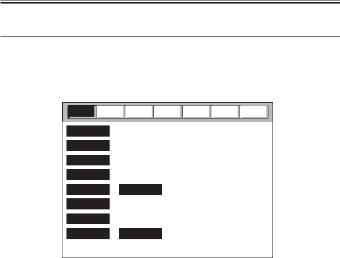
COPYRIGHT
©
2001 CANON INC. 2000 2000 2000 2000 CANON iR2200/iR2800/iR3300 REV.0 MAR. 2001
CHAPTER 5 SERVICE MODE
5-6 T
2 DISPLAY Control Display Mode
2.1 COPIER
The following screen will appear in response to COPIER>DISPLAY; the respective item
follows:
F05-201-01
Counter
Test
Option
Function
Adjust
I/O
Display
VERSION
USER
ACC-STS
ANALOG
CST-STS
JAM
ERR
HV-STS
SENSOR
ALARM-2

COPYRIGHT
©
2001 CANON INC. 2000 2000 2000 2000 CANON iR2200/iR2800/iR3300 REV.0 MAR. 2001
CHAPTER 5 SERVICE MODE
5-7 T
<VERSION>
Indicates the version of the machine and the version f the ROM on the accessories PCB.
Indication: <xx,yy>
Where, xx: version number, yy: R&D control number
DC-CON Indicates the version of the ROM on the DC controller PCB.
R-CON Indicates the version of the ROM on the reader controller PCB.
PANEL Indicates the version of the or on the control panel CPU PCB.
FEEDER Indicates the version of the ROM on the ADF controller PCB.
SORTER Indicates the version of the ROM on the finisher controller PCB.
NIB Indicates the version of the network software.
PS/PCL Indicates the version of the printer board (PS/PCL).
LIPS Indicates the version of the printer board (LIPS).
MN-CONT Indicates the version of the software of the main controller PCB.
BOOT-ROM Indicates the version of the BOOT ROM of the main controller.
Indication: for copier model, xx.yyC; for PSPCL model; xx.yyP; for PCL
model, xx.yyL
DIAG-DVC Indicates the version for the remote diagnostic device.
RUI Indicates the version of the RUI.
COPIER>DISPLAY>VERSION

COPYRIGHT
©
2001 CANON INC. 2000 2000 2000 2000 CANON iR2200/iR2800/iR3300 REV.0 MAR. 2001
CHAPTER 5 SERVICE MODE
5-8 T
PUNCH Indicates the version of the software of the punch unit.
LANG-EN Indicates the version of the English file.
LANG-FR Indicates the version of the French file.
LANG-DE Indicates the version of the German file.
LANG-IT Indicates the version of the Italian file.
LANG-JP Indicates the version of the Japanese file.
LANG-CS Indicates the version of the Czech file.
LANG-DA Indicates the version of the Danish file.
LANG-EL Indicates the version of the Greek file.
LANG-ES Indicates the version of the Spanish file.
LANG-ET Indicates the version of the Estonian file.
LANG-FI Indicates the version of the Finnish file.
LANG-HU Indicates the version of the Hungarian file.
LANG-KO Indicates the version of the Koran file.
LANG-NL Indicates the version of the Dutch file.
COPIER>DISPLAY>VERSION

COPYRIGHT
©
2001 CANON INC. 2000 2000 2000 2000 CANON iR2200/iR2800/iR3300 REV.0 MAR. 2001
CHAPTER 5 SERVICE MODE
5-9 T
LANG-NO Indicates the version of the Norwegian file.
LANG-PL Indicates the version of the Polish file.
LANG-PT Indicates the version of the Portuguese file.
LANG-RU Indicates the version of the Russian file.
LANG-SL Indicates the version of the Slovenian file.
LANG-SV Indicates the version of the Swedish file.
LANG-TW Indicates the version of the Chinese file (traditional).
LANG-ZH Indicates the version of the Chinese file (simplified).
COPIER>DISPLAY>VERSION

COPYRIGHT
©
2001 CANON INC. 2000 2000 2000 2000 CANON iR2200/iR2800/iR3300 REV.0 MAR. 2001
CHAPTER 5 SERVICE MODE
5-10 T
<USER>
Indicates items related to the User screen and the user.
LANGUAGE Indicates the language/paper size configuration used.
Indication <LANGUAGE xxyy.zz.aa>
Where,
xx (higher 2 characters): country code (See JIS.)
yy (lower 2 chargers): language code (See ISO639.)
zz: destination code (00: Canon, 01: OEM,
02: common (all))
aa: paper size configuration code (00: AB, 01:
Inch, 02: A, 03: all sizes)
MODEL Indicates the model (0: iR2200, 1: iR2800, 2: iR3300).
COPIER>DISPLAY>ACC-STS
<ACC-STS>
Indicates the connection of accessories.
FEEDER Indicates the connection of an ADF. (0: absent, 1: present)
SORTER Indicates the connection of a finisher and a puncher nit.
Indication: XY
Where,
X=0: absent, 1: finisher, 2: saddle finisher
Y=0: puncher unit absent; 1: 2-hole, 2: 2-/3-hole, 3: 4-hole (FRN), 4: 4-
hole (SWDN)
DECK Indicates the connection of a paper deck (option). (0: absent, 1: present)
CARD Indicates the connection of a card reader (option). (0: absent, 1: present)
DATA-CON Indicates the connection of a remote diagnostic device. (0: absent, 1: copy
data controller, 2: NE controller)
COPIER>DISPLAY>USER

COPYRIGHT
©
2001 CANON INC. 2000 2000 2000 2000 CANON iR2200/iR2800/iR3300 REV.0 MAR. 2001
CHAPTER 5 SERVICE MODE
5-11 T
RAM Indicates the size of memory mounted to the main controller. (64 MB, 128
MB)
NIB Indicates the connection of a network board. (0: absent, 1: Ethernet board,
2: TokenRing, 3: both)
LIPS-RAM Indicates the size of memory mounted on the LIPS board. (xx MB)
LIPS Indicates the connection of a LIPS board. (0: absent, 1: present)
PS/PCL Indicates the connection of a PS/PCL board. (0: absent, 1: PS/PCL, 2: PS
kanji)
NETWARE Indicates the installation of netware firmware. (0: absent, 1: installed)
COPIER>DISPLAY>ANALOG
<ANALOG>
Indicates the readings of analog sensors.
TEMP Indicates the machine inside temperature. (environment sensor; in °C)
HUM Indicates the machine inside humidity. (environment sensor; in % RH)
ABS-HUM Indicates the machine inside humidity absolute value. (sensor: in g)
DR-TEMP Indicates the temperature around the photosensitive drum. (drum sensor; in
°C)
FIX-C Indicates the temperature of the fixing heater. (main thermistor; in °C)
FIX-E Indicates the temperature of the edge of the fixing heater. (sub thermistor;
in °C)
COPIER>DISPLAY>ACC-STS

COPYRIGHT
©
2001 CANON INC. 2000 2000 2000 2000 CANON iR2200/iR2800/iR3300 REV.0 MAR. 2001
CHAPTER 5 SERVICE MODE
5-12 T
<CST-STS>
Indicates the size of paper in the cassettes and the manual feeder.
WIDTH-MF Indicates the width of paper in terms of paper size (manual feed).
COPIER>DISPLAY>CTS-STS
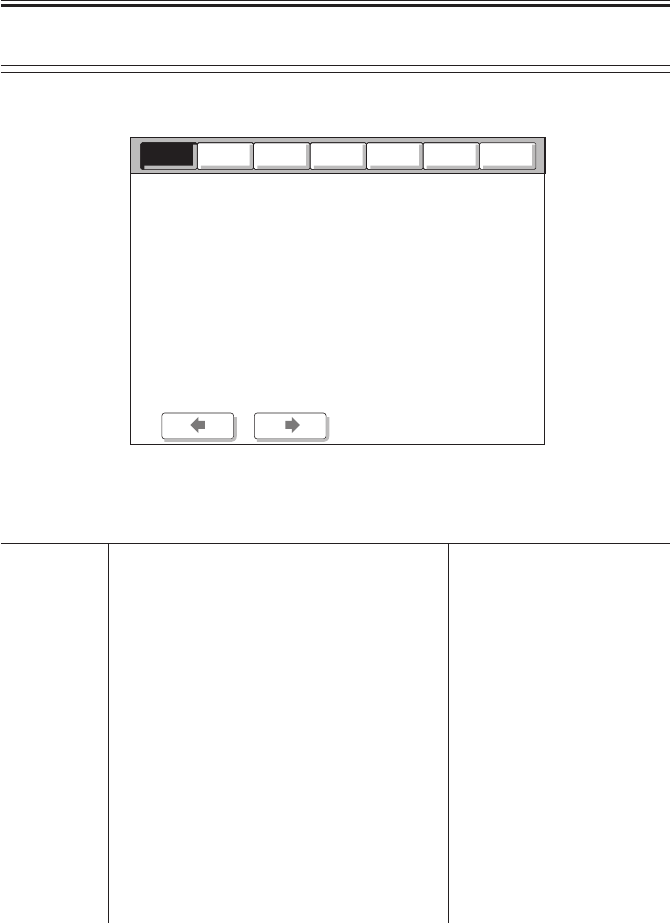
COPYRIGHT
©
2001 CANON INC. 2000 2000 2000 2000 CANON iR2200/iR2800/iR3300 REV.0 MAR. 2001
CHAPTER 5 SERVICE MODE
5-13 T
Item Description Remarks
AA Indicates the order of jams 1 to 50 (50 max.)
(the higher the number, the older the jam).
BBBB Indicates the date of occurrence. Month, day (2 characters each)
CCCC Indicates the time of occurrence. 24-hr notation
DDDD Indicates the time of recovery. 24-hr notation
E Indicates the location of occurrence. 0: copier
1: feeder
2: finisher
EFff Indicates a jam code. FF: type of jam (T05-201-01)
ff: jam sensor (T05-201-02)
For the feeder, see T05-201-04;
for the finisher, see T05-201-
05, -06.
G Indicates the source of paper. See T05-201-03.
HHHHHH Indicates the soft counter of the source of paper.
IIIII Indicates paper size.
COPIER>DISPLAY>JAM
COPIER>DISPLAY>JAM
<JAM>
Indicates jam data.
F05-201-02
Counter
Test
Option
Function
Adjust
I/O
Display
ERR 1/ 7 READY
AA
AA
AA
AA
AA
AA
AA
AA
BBBB
BBBB
BBBB
BBBB
BBBB
BBBB
BBBB
BBBB
CCCC
CCCC
CCCC
CCCC
CCCC
CCCC
CCCC
CCCC
DDDD
DDDD
DDDD
DDDD
DDDD
DDDD
DDDD
DDDD
EEEE
EEEE
EEEE
EEEE
EEEE
EEEE
EEEE
EEEE
HHHHHH
HHHHHH
HHHHHH
HHHHHH
HHHHHH
HHHHHH
HHHHHH
HHHHHH
FFff
FFff
FFff
FFff
FFff
FFff
FFff
FFff
IIIII
IIIII
IIIII
IIIII
IIIII
IIIII
IIIII
IIIII
G
G
G
G
G
G
G
G
< > < > < >

COPYRIGHT
©
2001 CANON INC. 2000 2000 2000 2000 CANON iR2200/iR2800/iR3300 REV.0 MAR. 2001
CHAPTER 5 SERVICE MODE
5-14 T
FF: Types of Jams
Code Type
00xx none
01xx delay jam
02xx stationary jam
0Axx power-on stationary jam
0Bxx cover open jam
9003 logic jam (*1)
9011 logic jam (*2)
10xx finisher jam
*1: standby jam from the Finisher-J1.
*2: image request absent jam.
T05-201-01
ff: Jam Sensors
Code Sensor
xx01 registration paper sensor (PS10)
xx02 multifeeder paper sensor (PS22)
xx03 pre-registration paper sensor (PS9)
xx04 vertical path paper sensor (Q1603)
xx05 cassette 1 re-try sensor (PS7)
xx06 cassette 2 re-try sensor (PS8)
xx07 cassette 3 re-try sensor (PS2C)
xx08 cassette 4 re-try sensor (PS3C)
xx09 deck pickup sensor (PS1D)
xx0A deck feed sensor (PS6D)
xx11 image leading edge sensor (PS12)
xx12 fixing/feed sensor (PS13)
xx13 No. 1 delivery sensor (PS15)
xx14 No. 2 delivery sensor (PS19B)/
relay delivery sensor (PS19Z)
xx15 No. 3 delivery sensor (PS21B)
xx21 duplex inlet paper sensor (PS17)
xx22 duplex output paper sensor (PS18)
xx33 front cover switch (SW3)
xx34 right cover open/closed sensor (PS23)
xx35 2-way delivery open/closed sensor (PS24B)/
relay delivery open/closed sensor (PS24Z)
xx36 right cover open/closed sensor (PS1C)
xx37 deck set sensor (PS5D)
xx39 finisher front cover sensor (S1)
T05-201-02
G: Source of Paper
Code Source
1 cassette 1
2 cassette 2
3 cassette 3
4 cassette 4
5 not used
6 not used
7 paper deck
8 manual feed tray
9 duplex unit
T05-201-03
FFff: Sensor/Type (jams in feeder)
Code Sensor/type Sensor used
0001 registration sensor delay PI6
0002 registration sensor PI6
stationary
0003 read sensor delay PI6, PI7
0004 read sensor stationary PI7
0005 delivery sensor delay PI7, PI8
0006 delivery sensor PI8
stationary
0007 ADF open PI1
0008 user ADF open PI1
0009 ADF cover open PI9
000A user cover open PI9
000B initial stationary PI6, PI7, PI8
000C pickup fault -
T05-201-04
COPIER>DISPLAY>JAM

COPYRIGHT
©
2001 CANON INC. 2000 2000 2000 2000 CANON iR2200/iR2800/iR3300 REV.0 MAR. 2001
CHAPTER 5 SERVICE MODE
5-15 T
FFff: Sensor/Type
(jams in Saddle Finisher-G1)
Code Sensor/type Sensor used
1006 stapler staple jam PI19
1007 power-on jam PI1, PI10
1008 cover open jam PI22, PI23,
MS2
1011 inlet sensor delay PI1
1012 folding potion sensor PI10
delay
1021 inlet sensor stationary PI1
1022 folding position sensor PI10
stationary
T05-201-05
FFff: Sensor/Type
(jams in Finisher-J1)
Code Sensor/type Sensor used
0003 inlet sensor delay S2
0004 inlet sensor stationary S2
0006 stapler staple jam S17
0007 power-on jam S2
0081 stack delivery S8
0082 stack return S3
0114 relay delivery sensor PS19Z
delay
0214 relay delivery sensor PS19Z
stationary
0B35 relay delivery cover PS24Z
open jam
0B39 front cover open jam S1
T05-201-06
COPIER>DISPLAY>JAM

COPYRIGHT
©
2001 CANON INC. 2000 2000 2000 2000 CANON iR2200/iR2800/iR3300 REV.0 MAR. 2001
CHAPTER 5 SERVICE MODE
5-16 T
<ERR>
Indicate error data.
F05-201-03
Item Description Remarks
AA Indicates the order of errors 1 to 50 (50 max.)
(the higher the number, the older the error).
BBBB Indicates the date of occurrence. Month, day (2 characters each)
CCCC Indicates the time of occurrence. 24-hr notation
DDDD Indicates the time of recovery. 24-hr notation.
EEEE Indicates an error code. See Chapter 6 “Self Diagnosis.”
EFff Indicate a detail code. If none, ‘0000’.
G Indicates the location of occurrence. 0: copier/main controller
1: feeder
2: finisher
3: CFF
4: reader
5: printer
6: PDL
7: fax
HH not used
Counter
Test
Option
Function
Adjust
I/O
Display
ERR 1/ 7 READY
AA
AA
AA
AA
AA
AA
AA
AA
BBBB
BBBB
BBBB
BBBB
BBBB
BBBB
BBBB
BBBB
CCCC
CCCC
CCCC
CCCC
CCCC
CCCC
CCCC
CCCC
DDDD
DDDD
DDDD
DDDD
DDDD
DDDD
DDDD
DDDD
EEEE
EEEE
EEEE
EEEE
EEEE
EEEE
EEEE
EEEE
FFff
FFff
FFff
FFff
FFff
FFff
FFff
FFff
HH
HH
HH
HH
HH
HH
HH
HH
G
G
G
G
G
G
G
G
< > < > < >
COPIER>DISPLAY>ERR

COPYRIGHT
©
2001 CANON INC. 2000 2000 2000 2000 CANON iR2200/iR2800/iR3300 REV.0 MAR. 2001
CHAPTER 5 SERVICE MODE
5-17 T
<HV-STS>
Indicates the measurements taken of voltage/current.
PRIMARY Indicates the level of current of primary charging in relation to photosensi-
tive drum resistance detection control (APVC).
Unit: µA
Reference:
• If 353 µA or less, the drum unit can well be used.
• 353<485 µA or less, the drum unit may be used without a problem.
• 485 µA or more, the drum unit should be replaced.
TR Indicates the mode selected for the level of current of transfer charging.
0: transfer constant voltage mode, 1: transfer constant voltage mode (mid),
2: transfer constant voltage mode (max.), 3: transfer constant voltage mode
(min.)
BIAS Indicates the developing bias DC level (in V)
TR-V Indicates the voltage level in relation to transfer charging roller resistance
detection control (ATVC). (in V)
Reference:
1500 to 6000V: the transfer charging system is normal.
6001V or more: the transfer charging roller may have a locking fault.
1499V or less: leakage and a transfer charging roller fault
are possibilities.
COPIER>DISPLAY>SENSOR
<SENSOR>
Indicates the condition of sensors.
DOC-SZ Indicates the size of the original detected by the original size sensor.
COPIER>DISPLAY>HV-STS
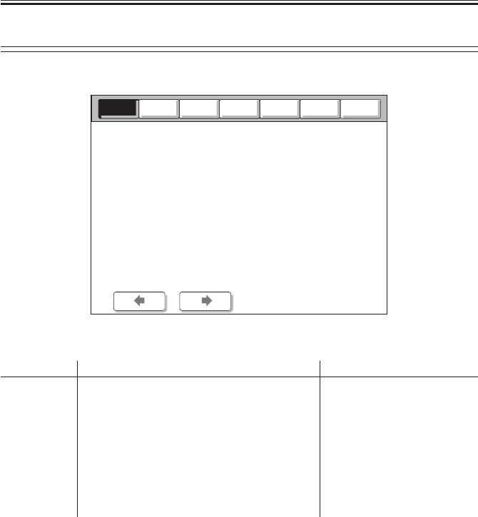
COPYRIGHT
©
2001 CANON INC. 2000 2000 2000 2000 CANON iR2200/iR2800/iR3300 REV.0 MAR. 2001
CHAPTER 5 SERVICE MODE
5-18 T
<ALARM-2>
Indicates alarm data.
F05-201-04
Item Description Remarks
AA Indicates the order of alarms 1 to 50
(the higher the number, the older the alarm).
BBBB Indicates the date of occurrence. Month/day (2 characters each)
CCCC Indicates the time of occurrence. Hour/minute (24-hr notation)
DDDD Indicates the time of return. Hour/minute (24-hr notation)
EEFFFF Indicates the total counter reading at time of See the table below.
occurrence.
GGGG Indicates the detail code. R&D control code.
HHHHHHHH Indicates the total counter of occurrence.
Counter
Test
Option
Function
Adjust
I/O
Display
ALARM-2 1/ 7 READY
< > < > < >
AA BBBB CCCC DDDD EEFFFF GGGG HHHHHHHH
COPIER>DISPLAY>ALAM-2

COPYRIGHT
©
2001 CANON INC. 2000 2000 2000 2000 CANON iR2200/iR2800/iR3300 REV.0 MAR. 2001
CHAPTER 5 SERVICE MODE
5-19 T
EE (location code) EE (location) FFFF (description)
02 scanner in reader unit 0002: Indicate of dirt on reading glass in stream
reading mode (small-size)
04 pickup/feed system 0008: paper deck lifter fault
0011: cassette 1 re-try alarm
0012: cassette 2 re-try alarm
0013: cassette 3 re-try alarm
0014: cassette 4 re-try alarm
0018: paper deck re-try alarm
61 stapler system of 0001: staple absent
sorter/finisher
62 saddle stitcher system 0001: stitch staple absent
65 puncher system of 0001: punch waste case full
sorter/finisher
FEEDER>DISPLAY
2.2 FEEDER
FEEDSIZE Indicates the size of the original detected by the ADF.
COPIER>DISPLAY>ALAM-2
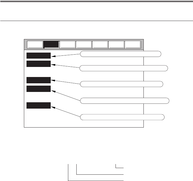
COPYRIGHT
©
2001 CANON INC. 2000 2000 2000 2000 CANON iR2200/iR2800/iR3300 REV.0 MAR. 2001
CHAPTER 5 SERVICE MODE
5-20 T
3 I/O, I/O Display mode
The fowling screen will appear in response to COPIER>I/O; discussions on items follow:
F05-301-01
<Guide to the screen>
P001 xxxxxxxxxxxxxxxx
bit 0
bit 15
address
Counter
Test
Option
Function
Adjust
Display
DC-CON
R-CON
FEEDER
SORTER
MN-CON
I/O
Input/output port of DC controller PCB
Input/output port of ADF controller PCB
Input/output port of finisher controller PCB
Input/output port of main controller PCB
Input/output port of reader controller PCB

COPYRIGHT
©
2001 CANON INC. 2000 2000 2000 2000 CANON iR2200/iR2800/iR3300 REV.0 MAR. 2001
CHAPTER 5 SERVICE MODE
5-21 T
3.1 DC-CON
Indicates the input/output ports of the DC controller PCBs.
<DC-CON (1/7)>
Address
bit
Notation
Description Remarks
P001 0 M1 main motor drive signal 0: ON
1
LAMP2
pre-exposure lamp ON signal 1: ON
2 M10 laser scanner motor dive signal 0: ON
3 M4 fixing motor dive signal 0: ON
4 M4 fixing motor low-speed drive signal 1: ON
5 CL1 vertical path clutch drive signal 1: ON
6 CL2 multifeeder clutch drive signal 1: ON
7 CL3 developing assembly clutch drive signal 1: ON
P002 0 SL1 pickup DOWN solenoid drive signal 1: ON
1 SL3Z relay delivery solenoid drive signal 1: ON
2 not used
3 SL5 multifeeder holding plate releasing solenoid 1: ON
drive signal
4 SL6 charging roller solenoid drive signal 1: ON
5 M9 registration motor drive OFF signal 1: off, 0: excited
6 not used
7 not used
P003 0 M2 pickup motor drive signal 1 -
1 M2 pickup motor drive signal 2 -
2 M2 pickup motor drive signal 3 -
3 M2 pickup motor drive signal 4 -
4M3
horizontal registration sensor shift motor pulse signal A
-
5M3
horizontal registration sensor shift motor pulse signal A*
-
6M3
horizontal registration sensor shift motor pulse signal B
-
7M3
horizontal registration sensor shift motor pulse signal B*
-
P004 0 FM1 developing fan (full speed ) signal 1: ON
1 FM2 fixing fan (full speed) signal 1: ON
2 FM1 developing fan (half speed) signal 1: ON
3 FM2 fixing fan (half speed signal) 1: ON
4 M8B 2-way delivery outlet motor pulse signal IN1 Inner 2-Way Tray-A1
M7Z relay delivery output motor pulse signal IN1 relay delivery assembly
5 M8B 2-way delivery output motor pulse signal IN2 Inner 2-Way Tray-A1
M7Z relay delivery outlet motor pulse signal IN2 relay delivery assembly
6 M8B 2-way delivery outlet motor pulse signal IN3 Inner 2-Way Tray-A1
M7Z relay delivery outlet motor pulse signal IN3 relay delivery assembly
7 M8B 2-way delivery outlet motor pulse signal IN4 Inner 2-way tray-A1
M7Z relay delivery outlet motor pulse signal IN4 relay delivery assembly
COPIER>I/O>DC-CON

COPYRIGHT
©
2001 CANON INC. 2000 2000 2000 2000 CANON iR2200/iR2800/iR3300 REV.0 MAR. 2001
CHAPTER 5 SERVICE MODE
5-22 T
<DC-CON (2/7)>
Address
bit
Notation
Description Remarks
P005 0 M6 duplex motor pulse signal IN1 -
1 M6 duplex motor pulse signal IN2 -
2 M6 duplex motor pulse signal IN3 -
3 M6 duplex motor pulse signal IN4 -
4 M6 duplex motor drive signal I0 -
5 M6 duplex motor drive signal I1 -
6 FM4 curl reducing fan 1 drive signal 1: ON
7 FM5 curl reducing fan 2 drive signal 1: ON
P006 0 primary DC charging motor signal 1: ON
1 primary charging ON signal 1: ON
2 static eliminator ON signal 1: ON
3 developing AC bias ON signal 1: ON
4 developing DC bias ON signal 1: ON
5 fixing bias ON signal 1: ON
6 heater relay ON signal 1: ON
7 M8B 2-way delivery outlet motor pulse signal I0 1: 70%, 0: 100%
P007 0 transfer mode signal 0 1: ON
1 transfer mode signal 1 1: ON
2 transfer mode signal 2 1: ON
3 transfer mode signal 3 1: ON
4 transfer ON signal 1: ON
5 scanner output signal 4 -
6 scanner output signal 5 -
7 not used
P008 0 S1 toner level detection signal 1: toner present
1 not use
2 S2 waste toner case full detection signal 1: full
3 M1 main motor lock detection signal 0: locked
4 M10 laser scanner motor lock detection signal 0: locked
5 M4 fixing motor lock detection signal 0: locked
6 24V detection signal 0: detected
7 SW3 front over open/close sensor signal 1: closed
P009 0 factory mode signal 0 -
1 factory mode signal 1 -
2 factory mode signal 2 -
3 factory mode signal 3 -
4 FM1 developing fan rotation detection signal 0: in rotation
5 FM2 fixing fan rotation detection signal 0: in rotation
6 FM4 curl reducing fan 1 rotation detection signal 0: in rotation
7 FM5 curl reducing fan 2 rotation detection signal 0: in rotation
COPIER>I/O>DC-CON

COPYRIGHT
©
2001 CANON INC. 2000 2000 2000 2000 CANON iR2200/iR2800/iR3300 REV.0 MAR. 2001
CHAPTER 5 SERVICE MODE
5-23 T
<DC-CON (3/7)>
Address
bit
Notation
Description Remarks
P010 0 M5 delivery motor pulse signal A_D0 -
1 M5 delivery motor pulse signal A_D1 -
2 M5 delivery motor pulse signal A_D2 -
3 M5 delivery motor pulse signal A_PHASE -
4 M5 delivery motor pulse signal B_D0 -
5 M5 delivery motor pulse signal B_D1 -
6 M5 delivery motor pulse signal B_D2 -
7 M5 delivery motor pulse signal B_PHASE -
8 M5 delivery motor pulse signal I0 -
9 not used
10 not used
11 not used
12 not used
13 not used
14 not used
15 not used
P011 0 M7B 2-way delivery inlet motor pulse signal A_D0 -
1 M7B 2-way delivery inlet motor pulse signal A_D1 -
2 M7B 2-way delivery inlet motor pulse signal A_D2 -
3 M7B 2-way delivery inlet motor pulse signal A_PHASE -
4 M7B 2-way delivery inlet motor pulse signal A_D0 -
5 M7B 2-way delivery inlet motor pulse signal A_D1 -
6 M7B 2-way delivery inlet motor pulse signal A_D2 -
7 M7B 2-way delivery inlet motor pulse signal lA_PHASE -
8 M7B 2-way delivery inlet motor pulse signal I0 -
9 not used
10 not used
11 not used
12 not used
13 not used
14 not used
15 not used
P012 0 laser output enable signal 0: enabled
1 printer output prepare signal -
2 transmission ready signal -
3 scanner start signal -
4 optional output signal 0 -
5 optional output signal 1 -
6 optional output signal 2 -
7 optional output signal 3 -
COPIER>I/O>DC-CON

COPYRIGHT
©
2001 CANON INC. 2000 2000 2000 2000 CANON iR2200/iR2800/iR3300 REV.0 MAR. 2001
CHAPTER 5 SERVICE MODE
5-24 T
<DC-CON (4/7)>
Address
bit
Notation
Description Remarks
P013 0 S4 cassette 1 cassette size detection signal bit 0 -
1 S4 cassette 1 cassette size detection signal bit 1 -
2 S4 cassette 1 cassette size detection signal bit 2 -
3 S4 cassette 1 cassette size detection signal bit 3 -
4 S4 cassette 1 cassette size detection signal bit 4 -
5 PS1 cassette 1 paper detection signal 1: paper absent
6 PS3 cassette 1 paper level detection signal bit 0 25% (bit6=0:bit7=1)
7 PS4 cassette 1 paper level detection signal bit 1 50% (bit6=1:bit7=1)
100% (bit7=0)
P014 0 S5 cassette 2 cassette size detection signal bit 0 -
1 S5 cassette 2 cassette size detection signal bit 1 -
2 S5 cassette 2 cassette size detection signal bit 2 -
3 S5 cassette 2 cassette size detection signal bit 3 -
4 S5 cassette 2 cassette size detection signal bit 4 -
5 PS2 cassette 2 paper detection signal 1: paper absent
6 PS5 cassette 2 paper level detection signal bit 0 25% (bit6=0:bit7=1)
7 PS6 cassette 2 paper level detection signal bit 1 50% (bit6=1:bit7=1)
100% (bit7=0)
P015 0 PS7 cassette 1 re-tray paper detection signal 1: paper present
1 PS8 cassette 2 re-tray paper detection signal 1: paper present
2 PS9 pre-registration paper detection signal 1: paper present
3 PS10 registration paper detection signal 1: paper present
4 PS11 horizontal registration paper detection signal 1: paper absent
5 PS13 fixing/feeding detection signal 1: paper absent
6 PS15 No. 1 delivery detection signal 1: paper present
7 PS16 No. 1 delivery full detection signal 1: paper present
P016 0 PS17 duplex inlet paper detection signal 1: paper absent
1 PS18 duplex outlet power detection signal 1: paper absent
2 PS19B No. 2 delivery detection signal 1: paper present
3 PS20B No. 2 delivery full detection signal 1: paper present
4 PS21B No. 3 delivery detection signal 1: paper present
5 PS22 multifeeder paper detection signal 1: paper absent
6 PS23 right cover open/closed detection signal 1: open
7 PS24B 2-way delivery open/closed detection signal 1: open
P017 0 optional input signal 0 -
1 optional input signal 1 -
2 optional input signal 2 -
3 optional input signal 3 -
4 optional input signal 4 -
5 not used
6 not used
7 not used
COPIER>I/O>DC-CON

COPYRIGHT
©
2001 CANON INC. 2000 2000 2000 2000 CANON iR2200/iR2800/iR3300 REV.0 MAR. 2001
CHAPTER 5 SERVICE MODE
5-25 T
<DC-CON (5/7)>
Address
bit
Notation
Description Remarks
P018 0 print start signal -
1 transmission request signal -
2 controller power supply inlet ready signal -
3 printer power supply inlet signal -
4 not used
5 not used
6 not used
7 not used
P019 0 BD cycle error signal 1: present
1 phsync cycle error signal 1: present
2 sub scanning select line interrupt signal -
3 image end signal -
4 not used
5 not used
6 not used
7 not used
P020 0 zero-cross signal -
1 heater trigger 1 signal 0: ON
2 heater trigger 2 signal 0: ON
3 heater error OFF signal 0: error
4 not used
5 not used
6 M9 registration motor phase A pulse signal -
7 M9 registration motor phase B pulse signal -
P021 0 PS26 fixing film rotation detection signal -
1 not used
2 not used
3 not used
4 not used
5 not used
6 finisher detection signal inner 2-way tray absent:
bit 6=1
7 saddle finisher detection signal finisher: bit6=0, bit 7=1
saddle finisher:
bit 6=0, bit 7=0
COPIER>I/O>DC-CON

COPYRIGHT
©
2001 CANON INC. 2000 2000 2000 2000 CANON iR2200/iR2800/iR3300 REV.0 MAR. 2001
CHAPTER 5 SERVICE MODE
5-26 T
<DC-CON (6/7)>
Address
bit
Notation
Description Remarks
P022 0 controller communication signal -
1 power supply communication signal -
2 controller communication signal -
3 power supply communication signal -
4 not used
5 power supply communication signal -
6 not used
7 not used
P23 0 TH1 main thermistor ON signal A/D
1 TH2 sub thermistor ON signal A/D
2 VR1 multifeeder paper width detection signal A/D
3 drum thermistor ON signal A/D
4 S3 humidity detection signal A/D
5 S3 room temperature detection signal A/D
6 AC monitor signal A/D 200V model only
7 not used
P024 0 RS232C detection signal for debug -
1 RS233C detection signal for debug -
2 not used
3 power supply communication signal -
4 not used
5 not used
6 not used
7 not used
P025 0 not used
1 ADC reception data signal -
2 ADC serial clock signal -
3 ADC transmission data signal -
4 error interrupt signal -
5 DDI interrupt signal -
6 power supply communication signal -
7 PS12 image leading edge sensor detection signal 1: paper present
P026 0 not used
1 not used
2 not used
3 not used
4 not used
5 not used
6 not used
7 not used
COPIER>I/O>DC-CON

COPYRIGHT
©
2001 CANON INC. 2000 2000 2000 2000 CANON iR2200/iR2800/iR3300 REV.0 MAR. 2001
CHAPTER 5 SERVICE MODE
5-27 T
<DC-CON (7/7)>
Address
bit
Notation
Description Remarks
P027 0 100/200V detection signal 1: 100V, 0: 200V
1 not used
2 ADC chip select signal -
3 not used
4 not used
5 not used
6 not used
7 used as Φ terminal -
P028 0 CPU check LED On signal -
1 not used
2 not used
3 not used
4 not used
5 not used
6 not used
7 not used
P29 TH1 main thermistor ON signal
A/D hexadecimal notation
P30 TH2 sub thermistor ON signal
A/D hexadecimal notation
P31 VR1 multifeeder paper width detection signal
A/D hexadecimal notation
P32 drum thermistor ON signal
A/D hexadecimal notation
P33 S3 humidity detention signal
A/D hexadecimal notation
P34 S3 room temperature detection signal
A/D hexadecimal notation
P35 AC monitor signal
A/D hexadecimal notation
COPIER>I/O>DC-CON

COPYRIGHT
©
2001 CANON INC. 2000 2000 2000 2000 CANON iR2200/iR2800/iR3300 REV.0 MAR. 2001
CHAPTER 5 SERVICE MODE
5-28 T
3.2 R-CON
Indicates the input/output ports of the reader controller PCB.
<R-CON (1/3)>
Address
bit
Notation
Description Remarks
IO-P01 0 M400 scanner motor clock signal clock signal
1 M400 scanner rotation direction signal 0: cw
2 M400 scanner motor drier drive enable signal 0: drive enabled
3 not used
4 M400 scanner motor excitation original return signal/ 1→0: return to original
motor driver controller reset signal
5 M400 scanner motor excitation mode set signal default
6 M400 scanner motor excitation mode set signal default
7 not used
IO-P02 0 EEPROM several clock signal clock signal
1 EEPROM chip select signal 1: output
2 EEPROM read serial data signal data
3 EEPROM write serial data signal data
4 scanner reception ready signal (DDI) 0: ready to receive
5 scanner power supply ready signal (DDI) 0: ready
6 not used
7 +12V ON/OFF control signal for CCD 1: ON
IO-P03 0 serial transmission signal for DDI data
1 serial transmission signal for RS-232C data
2 serial reception signal for DDI data
3 serial transmission signal for RS-232C data
4 CCD drive signal output control signal 1: ON
5 SD1 original sensor drive control signal 0: ON
6 not used
7 not used
IO-P04 0 not used
1 not used
2 not used
3 not used
4 SD1 original sensor signal 0: ON
5 not used
6 M400 scanner drive current set signal analog signal
7 not used
COPIER>I/O>R-CON

COPYRIGHT
©
2001 CANON INC. 2000 2000 2000 2000 CANON iR2200/iR2800/iR3300 REV.0 MAR. 2001
CHAPTER 5 SERVICE MODE
5-29 T
<R-CON (2/3)>
Address
bit
Notation
Description Remarks
IO-P05 0 printer start signal (DDI) 0: ON
1 analog processor data signal data
2 analog processor clock signal clock signal
3 analog processor load signal data
4 not used
5 not used
6 not used
7 not used
IO-P06 0 M400 motor drive current mode signal 0: new current mode
1 PCB check mode signal 0: check mode
2 FL1N original exposure lamp ON/OFF control signal 1: ON
3 FL1N original exposure lamp inverter error signal 1: error
4 PS400 scanner home position signal 1: HP
5 image leading edge signal (ADF) 1: ADF image leading
edge interrupt
6 PS401 copyboard cover open/closed detection signal 1: copyboard cover
closed
7 not used
IO-P07 0 not used
1 not used
2 not used
3 not used
4 not used
5 IP-Lifter/IP-STD ID signal 1: Lifter model
6 +24V monitor (L: +24V live) signal 0: 24V ON
7 +3.3V voltage drop detection signal 1: detected
IO-P08 0 general port (0) for DDI: reader → controller not used
1 general port (1) for DDI: reader → controller not used
2 general port (2) for DDI: reader → controller not used
3 not used
4 not used
5 not used
6 not used
7 not used
IO-P09 0 ON LED (not used)
1 not used
2 not used
3 not used
4 not used
5 not used
6 not used
7 not used
COPIER>I/O>R-CON

COPYRIGHT
©
2001 CANON INC. 2000 2000 2000 2000 CANON iR2200/iR2800/iR3300 REV.0 MAR. 2001
CHAPTER 5 SERVICE MODE
5-30 T
<R-CON (3/3)>
Address
bit
Notation
Description Remarks
IO-P10 0-7 not used
IO-P11 0-7 not used
IO-P12 0-7 not used
IO-P13 0 general port (0) for DDI: controller → reader 1*
1 general port (1) for DDI: controller → reader not used
2 general port (2) for DDI: controller → reader not used
3 controller power supply ready signal (DDI) 0: ready
4 controller reception enable signal (DDI) 0: ready to receive
5 no used
6 not used
7 not used
*1: If the port is ‘0’ when 24V is supplied, the initial rotation is omitted (to prevent turning on
the reader in response to a PING command while the machine is in sleep mode); if ‘1’, the initial
operation is executed.
COPIER>I/O>R-CON

COPYRIGHT
©
2001 CANON INC. 2000 2000 2000 2000 CANON iR2200/iR2800/iR3300 REV.0 MAR. 2001
CHAPTER 5 SERVICE MODE
5-31 T
3.3 MN-CON
Indicates the input/output ports for the main controller PCB.
<MN-CON (1/2)>
Address
bit
Notation
Description Remarks
P001 7 GPDATA not used (fixed; 1)
6 not used (fixed; 1)
5 LED1008 for check on operation
4 fan ON cooling fan control
3 PCI power save control 1: normal operation
2 watchdog timer clear
1 PWR2 1: normal operation
0 PWR1 1: normal operation
P002 3 SPI SPRTST signal (printer start-up signal) 0: reader image start
2 input for DDI-S general not used
1 input for DDI-S general not used
0 input for DDI-S general not used
P003 3 PPI PSCNST signal (scanner start-up signal) 0: reader start
2 input for DDI-P general not used
1 input for DDI-P general not used
0 input for DDI-P general not used
P004 3 SPO SSCNST signal not used
2 3.3V non-all night power OFF signal 0: normal (ON),
1=5W (OFF)
sleep mode
1 output for DDI-S general not used
0 output for DDI-S general not used
P005 3 PPO PPRTST signal 0: printer image start
2 output for DDI-P general not used
1 output for DDI-P general not used
0 output for DDI-P general not used
P006 7 GPI HD connection detection 1: HD present
6 serial EEPROM D0 access port for EEPORM
5 operation enable (coin robot) 1: enabled
4 operation enable (CC-IV) 1: enabled
3 serial ROM connection detection 1: connected
2 flash RPOM R/B# 0: Busy, 1: Ready
1 parallel EEPROM R/B# for factory
0 battery alarm 0: Normal, 1: Error
COPIER>I/O>MN-CON

COPYRIGHT
©
2001 CANON INC. 2000 2000 2000 2000 CANON iR2200/iR2800/iR3300 REV.0 MAR. 2001
CHAPTER 5 SERVICE MODE
5-32 T
<MN-CON (2/2)>
Address
bit
Notation
Description Remarks
P007 15 GPO fax SSB forced reset 0: Reset, 1: Normal
14 parallel EEPROM write protect for factory
13 not used
12 LCD back-light control signal 1: ON
11 coin robot delivery count 1: count
10 coin robot pickup count 1: count
9 delivery count 1: count
8 pickup count 1: count
7 serial EEPROM DIN for factory
6 serial EPROM SCK for factory
5 serial EEPROM CS for factory
4 PCI (PDL) soft reset 0: LIPS board forced
reset
3 not used
2 SP0 (2) output (2) for
DDI-S general
1 not used
0 battery charge control 0: Enable, 1: Disable
P008 7 IPC-PA not used
6 not used
5 battery board detect 0: present
4 BW UI detect 0: B/W UI present
3 color UI detect 0: color UI present
2 FOPTI0N2 for fax SSB ID
1 FOPTI0N1 for fax SSB ID
0 FOPTI0N0 for fax SSB ID
P009 7-0 IPC-PB not used 0: fixed
P010 7-0 IPC-PO not used 0: fixed
COPIER>I/O>MN-COM

COPYRIGHT
©
2001 CANON INC. 2000 2000 2000 2000 CANON iR2200/iR2800/iR3300 REV.0 MAR. 2001
CHAPTER 5 SERVICE MODE
5-33 T
3.4 FEEDER
Indicates the input/output ports of the ADF controller PCB.
<FEEDER (1/2)>
Address
bit
Notation
Description Remarks
IO-P01 0 not used
(output) 1 not used
2 not used
3 not used
4 not used
5 LED original detection LED ON signal 0: ON
6 SL1 locking solenoid drive signal 0: ON
7 SL2 stamp solenoid drive signal 0: ON
IO-P02 0 PI8 delivery reversal sensor signal 1: paper present
(input) 1 PI7 read sensor signal 1: paper present
2 PI6 registration sensor signal 1: paper present
3 PI1 ADF open/closed sensor signal 1: open
4 M1 pickup motor phase A output -
5 M1 pickup motor phase A* signal -
6 M1 pickup motor phase B output -
7 M1 pickup motor phase B* output -
IO-P03 0 not used
(input) 1 not used
2 image leading edge signal -
3 not used
4 not used
5 not used
6 not used
7 not used
IO-P04 0 EEPROM data input -
1 EEPROM data output -
2 EEPROM clock -
3 EEPROM chip select -
4 PI10 original set sensor signal 1: paper present
5 PI9 cover open/close sensor signal 0: open
6 M2 feed motor clock signal
7 M1 pickup motor clock signal
COPIER>I/O>FEEDER

COPYRIGHT
©
2001 CANON INC. 2000 2000 2000 2000 CANON iR2200/iR2800/iR3300 REV.0 MAR. 2001
CHAPTER 5 SERVICE MODE
5-34 T
<FEEDER (2/2)>
Address
bit
Notation
Description Remarks
IO-P05 0 VR1 original width volume -
(input) 1 PI5 last original sensor signal -
2 PI4 tray sensor 2 -
3 PI3 tray sensor 1 -
4 PI2 A4R/LTR ID sensor -
5 push switch -
6 M2 feed motor V ref -
7 M1 pickup motor V ref -
IO-P06 0 M2 feed motor phase A output -
(output)
1 M2 feed motor phase A* output -
2 M2 feed motor phase B output -
3 M2 feed motor phase B* output -
4 not used
5 not used
6 PI7 read sensor signal 1: paper prevent
7 not used
IO-P07 0-7 not used
IO-P08 0-7 not used
IO-P09 0 LED4 LED ON signal 4 -
(output)
1 LED3 LED ON signal 3 -
2 LED2 LED ON signal 2 -
3 LED1 LED ON signal 1 -
4 not used
5 not used
6 not used
7 not used
IO-P10 0 DIPSW8 mode set DIP switch 8 -
(input) 1 DIPSW7 mode set DIP switch 7 -
2 DIPSW6 mode set DIP switch 6 -
3 DIPSW5 mode set DIP switch 5 -
4 DIPSW4 mode set DIP switch 4 -
5 DIPSW3 mode set DIP switch 3 -
6 DIPSW2 mode set DIP switch 2 -
7 DIPSW1 mode set DIP switch 1 -
IO-P11 0-7 not used
AD-P01
VR1 original width volume (analog port)
AD-P02
M2 feed motor current level (analog port)
AD-P03
M1 pickup motor current level (analog port)
COPIER>I/O>FEEDER

COPYRIGHT
©
2001 CANON INC. 2000 2000 2000 2000 CANON iR2200/iR2800/iR3300 REV.0 MAR. 2001
CHAPTER 5 SERVICE MODE
5-35 T
3.5 SORTER
Indicates the input/output ports for the finisher controller PCB.
<SORTER (1/8)>
3.5.1 Finisher-J1
Address
bit
Notation
Description Remarks
IO-P001
0 not used
(input) 1 not used
2 S10 stack tray paper height sensor signal 1: upper limit
3 S1 fisher front cover sensor signal 1: closed
4 S11 stack tray paper sensor signal 1: paper present
5 S12 stack tray lower limit sensor signal 1: lower limit
6 S13 stack tray upper limit sensor signal 1: upper limit
7 S3 return roller home position sensor signal 1: HP
IO-P002
0 S11 stack tray paper sensor signal 1: HP
(input) 1 IPC chip select 1: selected
2 S2 input sensor signal 1: paper present
3 S4 stack retaining lever home position sensor signal 0: HP
4-7 not used
IO-P003
0 S7 rear alignment home position sensor signal 1: HP
(input) 1 S6 front alignment home position sensor signal 1: HP
2 S8 stack delivery lever home position sensor signal 0: HP
3 S5 intermediate handling tray paper sensor signal 1: paper present
4 S14 staple cartridge sensor signal 0: detected
5 S15 staple absent sensor 0: detected
6 S16 stapling home position sensor signal 0: detected
7 S17 stapler edging sensor signal 0: detected
IO-P004
0 delivery motor clock sensor signal -
(input) 1 S9 stack tray up/down clock sensor signal -
2-7 not used
IO-P005
0 M5 stack tray ascent/decent motor CW signal 1: up ON
(output)
1 not used
2 M5 stack try ascent/descent motor CCW signal 1: down ON
3-4 not used
5 M1 delivery motor current switch 2 (T05-301-01)
6-7 not used
COPIER>I/O>SORTER

COPYRIGHT
©
2001 CANON INC. 2000 2000 2000 2000 CANON iR2200/iR2800/iR3300 REV.0 MAR. 2001
CHAPTER 5 SERVICE MODE
5-36 T
<SORTER (2/8)>
Address
bit
Notation
Description Remarks
IO-P006
0 M3/M4 alignment motor pulse INA -
(input) 1 M3/M4 alignment motor pulse INB -
2 M4 rear alignment motor enable signal 1: enable
3 M3 front alignment motor enable signal 1: enable
4 M2 stack delivery motor pulse INA -
5 M2 stack delivery motor pulse INB -
6 M6 stapler motor CW2 signal 0: CW ON
7 M6 stapler motor CCW2 signal 0: CCW ON
IO-P007
0 M6 stapler motor CW signal 0: CW ON
(input) 1 M6 stapler motor CCW signal 0: CCW ON
2 M5 stack tray ascent/descent motor CW2 signal 1: up ON
3 M5 stack tray ascent/descent motor CCW2 signal 1: down ON
4 M1 delivery motor pulse INA -
5 M1 delivery motor pulse INB -
6 not used
7 M1 delivery motor OFF signal 1: current ON
IO-P008
0 SW1 push switch signal 0: ON
(input) 1-6 not used
7 24VP detection signal 0: power ON
IO-P009
0-7 not used
IO-P010
0 DSW1-0 mode set DIP switch 0 0: ON
(input) 1 DSW1-1 mode set DIP switch 1 0: ON
2 DSW1-2 mode set DIP switch 2 0: ON
3 DSW1-3 mode set DIP switch 3 0: ON
4 DSW1-4 mode set DIP switch 4 0: ON
5 DSW1-5 mode set DIP switch 5 0: ON
6 DSW1-6 mode set DIP switch 6 0: ON
7 DSW1-7 mode set DIP switch 7 0: ON
IO-P011
0 LED1 LED ON signal 1 0: ON
(input) 1 LED2 LED ON signal 2 0: ON
2 LED3 LED ON signal 3 0: ON
3 M1 delivery motor current switch 1 signal (T05-301-01)
4 M2 stack delivery motor current switch 1 signal 0: current high
5 M2 stack delivery motor current switch 2 signal 0: current medium
6 M4 rear alignment motor current switch signal 0: current high
7 M3 front alignment motor current switch signal 0: current high
COPIER>I/O>SORTER

COPYRIGHT
©
2001 CANON INC. 2000 2000 2000 2000 CANON iR2200/iR2800/iR3300 REV.0 MAR. 2001
CHAPTER 5 SERVICE MODE
5-37 T
<SORTER (3/8)>
Address
bit
Notation
Description Remarks
IO-P012
0-7 not used
IO-P013
0-7 not used
IO-P014
0-7 not used
IO-P015
0-7 not used
IO-P016
0-7 not used
IO-P017
0-7 not used
IO-P018
0-7 not used
IO-P019
0-7 not used
IO-P020
0-7 not used
IO-P021
0-7 not used
IO-P022
0-7 not used
IO-P023
0-7 not used
IO-P024
0-7 not used
IO-P025
0-7 not used
IO-P026
0-7 not used
IO-P027
0-7 not used
IO-P028
0-7 not used
IO-P029
0-7 not used
IO-P030
0-7 not used
IO-P031
0-7 not used
IO-P032
0-7 not used
IO-P033
0-7 not used
IO-P034
0-7 not used
IO-P035
0-7 not used
IO-P036
0-7 not used
IO-P037
0-7 not used
IO-P038
0-7 not used
COPIER>I/O>SORTER

COPYRIGHT
©
2001 CANON INC. 2000 2000 2000 2000 CANON iR2200/iR2800/iR3300 REV.0 MAR. 2001
CHAPTER 5 SERVICE MODE
5-38 T
<SORTER (4/8)>
3.5.2 Saddle Finisher-G1
Address
bit
Notation
Description Remarks
P001 0 M4 front aligning plate motor phase A output 0: ON
(output)
1 M4 front aligning plate motor phase B output 0: ON
2 M8 slide moor phase A output 0: ON
3 M8 slide motor phase B output 0: ON
4 M3 delivery motor phase A output 0: ON
5 M3 delivery motor phase A* output 1: ON
6 M3 delivery motor phase B output 0: ON
7 M3 delivery motor phase B* output 1: ON
P002 0 M2 paddle motor phase A output 0: ON
(output)
1 M2 paddle motor phase A* output 1: ON
2 M2 paddle motor phase B output 0: ON
3 M2 paddle motor phase B* output 1: ON
4 M6 shift motor UP drive output -
5 M6 shift motor DOWN drive output -
6 M7 bind motor PWM output 0: ON
7 M7 bind motor clock sensor input 0: ON
P003 0 puncher unit transmission signal (output)
1 commercial device TXD (output)
2 puncher unit reception signal (input)
3 commercial device RXD (input)
4 PI24 full stack sensor (full detection) 1: FULL
5 CL1 bind clutch 1: ON
6-7 not used
P004 0 not used
(input) 1 push switch 1, 2 -
2 DIP switch 7, 8 -
3 DIP switch 5, 6 -
4 DIP switch 3, 4 -
5 DIP switch 1, 2 -
6 PI10 fold position sensor light emission (output) -
7 PI10 fold position sensor (analog) -
P005 0 EEPROM chip select 1: selected
(output)
1 EEPROM/DA clock output (used in common) -
2 EEPROM/DA data output (used in common) -
3 DA load signal output (used in common) 1: load
4-7 not used
COPIER>I/O>SORTER

COPYRIGHT
©
2001 CANON INC. 2000 2000 2000 2000 CANON iR2200/iR2800/iR3300 REV.0 MAR. 2001
CHAPTER 5 SERVICE MODE
5-39 T
<SORTER (5/8)>
Address
bit
Notation
Description Remarks
P006 0 PI21 cartridge sensor signal 1: ready
(input) 1 PI20 staple sensor signal 1: staple ascent
2 M5 rear alignment motor phase A (output) 0: ON
3 M5 rear alignment motor phase B (output) 0: ON
4 PI19 stapler drive home position sensor signal 0: HP
5 PI18 slide home position sensors signal 0: HP
6 PI7 delivery belt home position sensor signal 1: HP
7 commercial device REQ
P007 0-4 not used
(input) 5 PI10 fold position sensor signal 1: paper present
6 PI17 shift motor clock sensor signal
7 PI1P punch home position sensor 0: HP
P008 0 M1 feed motor phase A output 0: ON
(output)
1 M1 feed motor phase A* output 1: ON
2 M1 feed motor phase B output 0: ON
3 M1 feed motor phase B* output 1: ON
4 M8/4, 5 slide/aligning plate motor current cut -
5 not used
6 not used
7 PI8 tray paper sensor (input) 1: paper present
P009 0 M7 bind motor (CW) -
(output)
1 M7 bind motor (CCW) -
2 M6 shift motor enable signal -
3-7 not used
P010 0 PI9 paper sensor (input) 1: paper detected
(input) 1 PI4 front aligning plate home position sensor signal 0: HP
2 EEPROM data input -
3-7 not used
P011 0 PI16 shift lower limit sensor signal 1: limit
(input) 1 PI15 shift upper limit sensor signal 1: limit
2 power supply monitor signal 0: power ON
3 PI6 handling tray paper sensor signal 1: paper present
4 push switch 3 signal 0: ON
5 MS3 stapler safety detecting switch signal 1: open
6 MS1 front cover open detecting switch signal 1: open
7 MS2 joint open detecting switch signal 1: open
COPIER>I/O>SORTER

COPYRIGHT
©
2001 CANON INC. 2000 2000 2000 2000 CANON iR2200/iR2800/iR3300 REV.0 MAR. 2001
CHAPTER 5 SERVICE MODE
5-40 T
<SORTER (6/8)>
Address
bit
Notation
Description Remarks
P012 0 PI23 upper cover open sensor signal 1: open
(input) 1 PI22 front cover open sensor signal 1: open
2 PI5 rear aligning plate home position sensor signal 0: HP
3 PI3 stack roller home position sensor signal 0: HP
4 PI2 paddle home position sensor signal 0: HP
5 PI1 inlet paper sensor signal 0: paper present
6 PI11 fold home position sensor signal 1: HP
7 stapler connection signal 1: connected
P013 0 PI12 fold roller home position sensor signal 0: HP
(output)
1 punch connection signal 0: connected
2 PI13 bid tray paper sensor signal (input) 1: paper present
3 power save switch signal 1: power save mode
4 LED1 LED ON signal 1 0: ON
5 LED2 LED ON signal 2 0: ON
6 LED3 LED ON signal 3 0: ON
7 commercial device ACK 1: paper present
P014 0 DPISW1 bit 1 signal 0: ON
(input) 1 DPISW1 bit 2 signal 0: ON
2 DPISW1 bit 3 signal 0: ON
3 DPISW1 bit 4 signal 0: ON
4 DPISW1 bit 5 signal 0: ON
5 DPISW1 bit 6 signal 0: ON
6 DPISW1 bit 7 signal 0: ON
7 DPISW1 bit 8 signal 0: ON
P015 0 PUSHSW1 signal 0: ON
(input) 1 PUSHSW2 signal 0: ON
2 PUSHSW3 signal 0: ON
3-7 not used
P023 PI10 fold position sensor (analog port)
P024 not used (analog port)
P025 push switch 1, 2 (analog port)
P026 DIP switch 7, 8 (analog port)
P027 DIP switch 5, 6 (analog port)
P028 DIP switch 3, 4 (analog port)
P029 DIP switch 1, 2 (analog port)
P030 PI10 fold position sensor (light emission; output) (analog port)
COPIER>I/O>SORTER

COPYRIGHT
©
2001 CANON INC. 2000 2000 2000 2000 CANON iR2200/iR2800/iR3300 REV.0 MAR. 2001
CHAPTER 5 SERVICE MODE
5-41 T
<SORTER (7/8)>
3.5.3 Puncher Unit (Saddle Finisher-G1)
Address
bit
Notation
Description Remarks
P016 0 ladder circuit bit 1 -
(output)
1 ladder circuit bit 2 -
2 ladder circuit bit 3 -
3 ladder circuit bit 4 -
4 ladder circuit bit 5 -
5 ladder circuit bit 6 -
6 ladder circuit bit 7 -
7 ladder circuit bit 8 -
P017 0 PI1P punch home position sensor signal 0: HP
(input) 1 PI2P horizontal registration home position signal 1: HP
2, 3 not used
4 DIPSW1001 bit 1 signal 0: ON
5 DIPSW1001 bit 2 signal 0: ON
6 DIPSW1001 bit 3 signal 0: ON
7 DIPSW1001 bit 4 signal 0: ON
P018 0 PSW1 push SW1 signal 0: ON
(input) 1 PSW2 push SW2 signal 0: ON
2, 3 not used
4 power detection signal 0: power OFF
5 LED1 LED ON signal 1 (output) -
6 LED2 LEE ON signal 2 (output) -
7 LED3 LED ON signal 3 (output) -
P019 0 horizontal registration sensor light intensity level UP:
adjustment signal intensity increased
(output)
1 registration sensor light intensity adjusted signal level UP:
intensity increased
2, 3 not used
4 EEPROM DO (input) -
5 EEPROM DI -
6 EEPROM CLK -
7 EEPROM CS -
P020 0, 1 not used
(input) 2 registration interrupt horizontal registration signal H: blocked
3 REQ -
4 HFS communication RXD -
5 HFS communication TXD (output) -
6 not used
7 ACK (output)
COPIER>I/O>SORTER

COPYRIGHT
©
2001 CANON INC. 2000 2000 2000 2000 CANON iR2200/iR2800/iR3300 REV.0 MAR. 2001
CHAPTER 5 SERVICE MODE
5-42 T
<SORTER (8/8)>
Address
bit
Notation
Description Remarks
P021 0 M2P horizontal registration motor current set -
(output)
1 M2P horizontal registration motor current set -
2 M2P horizontal registration motor phase B output -
3 M2P horizontal registration motor phase A output -
4 M1P punch motor REV -
5 M1P punch motor FWD -
6 M1P punch motor PWM -
7 M1P punch motor encoder (input) 0: blocked
P022 0, 1 not used
(input) 2 dust sensor 1: full
3 registration sensor 5 horizontal registration -
4 registration sensor 4 B5R -
5 registration sensor 3 A4R -
6 registration sensor 2 B4 -
7 registration sensor 1 A4 -
P031 dust sensor signal 1: full (analog port)
P032 registration sensor 5 horizontal registration (analog port)
P033 registration sensor 4 B5R (analog port)
P034 registration sensor 3 A4R (analog port)
P035 registration sensor 2 B4 (analog port)
P036 registration sensor 1 A4 (analog port)
P037 horizontal registration sensor light intensity level UP:
adjustment intensity increased
P038 registration sensor light intensity adjustment level UP:
intensity increased
COPIER>I/O>SORTER

COPYRIGHT
©
2001 CANON INC. 2000 2000 2000 2000 CANON iR2200/iR2800/iR3300 REV.0 MAR. 2001
CHAPTER 5 SERVICE MODE
5-43 T
delivery motor current switch 1 delivery motor current switch 2 Current (A)
(P011-3) (P005-5)
1 1 0.1
0 1 0.3
0 0 0.5
T05-301-01
COPIER>I/O>SORTER
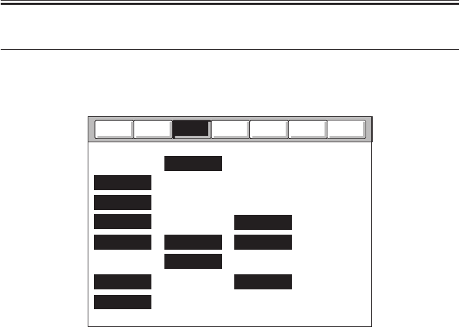
COPYRIGHT
©
2001 CANON INC. 2000 2000 2000 2000 CANON iR2200/iR2800/iR3300 REV.0 MAR. 2001
CHAPTER 5 SERVICE MODE
5-44 T
4 ADJUST Adjustment Mode
4.1 COPIER
The following screen will appear in response to COPIER>ADJUST:
F05-401-01
Counter
Test
Option
Function
I/O
Display
AE
ADJ-XY
CCD
LASER
BLANK
HV-TR
DEVELOP MISC
DENS
HV-PRI CST-ADJ
FEED-ADJ
Adjust
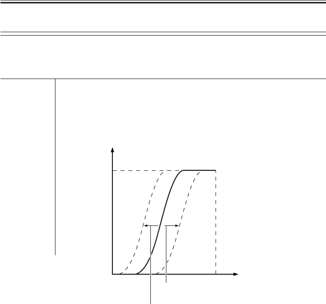
COPYRIGHT
©
2001 CANON INC. 2000 2000 2000 2000 CANON iR2200/iR2800/iR3300 REV.0 MAR. 2001
CHAPTER 5 SERVICE MODE
5-45 T
<AE>
Use it to execute AE adjustment.
If you have cleared the RAM on the reader controller PCB, enter the settings indicated on
the service label.
AE-TBL Use it to adjust the density of text for image density adjustment.
Range of 1 to 9; default: 5
adjustment
F05-401-02
White
White
Original density
A lower setting generates darker text.
Copy density
A higher setting generates darker text.
COPIER>ADJUST>AE
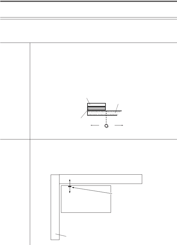
COPYRIGHT
©
2001 CANON INC. 2000 2000 2000 2000 CANON iR2200/iR2800/iR3300 REV.0 MAR. 2001
CHAPTER 5 SERVICE MODE
5-46 T
<ADJ-XY>
Use it to adjust the image read start position.
If you have cleared the RAM on the reader controller PCB and replaced the PCB, use it to
enter the settings indicated on the service label.
ADJ-X Use it to adjust the scanner image leading edge (x direction).
Range of 250 to 290 (‘1’ being 0.1mm)
adjustment
Caution Be sure to execute it before adjusting the margin.
Do not use this mode to create a margin.
F05-401-03
ADJ-Y Use it to adjust the CCD read start position (X direction).
Range of 100 to 400 (‘1’ being 0.1 mm)
adjustment
F05-401-04
Vertical side plate
Standard white plate
Higher setting
Lower setting
Copyboard glass
Lower setting
Higher setting
Original
Vertical size plate
Read start position
COPIER>ADJUST>ADJ-XY
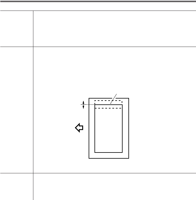
COPYRIGHT
©
2001 CANON INC. 2000 2000 2000 2000 CANON iR2200/iR2800/iR3300 REV.0 MAR. 2001
CHAPTER 5 SERVICE MODE
5-47 T
ADJ-S Use it to adjust the scanner home position.
Range of 16 to 128
adjustment
Caution Do not use this mode; it is for factory use only.
ADJ-Y-DF Use it to adjust the read start position in main scanning direction when the
ADF is in use (ADF horizontal registration adjustment).
Range of 100 to 400 (‘1’ being 0.1 mm)
adjustment
F05-401-06
STRD-POS Use it to adjust the CCD read position for stream reading.
Range of 0 to 60 (‘1’ being 0.1 mm)
adjustment
Feed direction
Higher setting
Lower setting
Print image
COPIER>ADJUST>ADJ-XY

COPYRIGHT
©
2001 CANON INC. 2000 2000 2000 2000 CANON iR2200/iR2800/iR3300 REV.0 MAR. 2001
CHAPTER 5 SERVICE MODE
5-48 T
<CCD>
Use it to make CCD/shading-related adjustments.
If faulty images are generated after the execution of COPIER>FUNCTION>CCD>CCD-
ADJ, enter the settings indicated on the service label.
SH-TRGT Use it to enter the white level target value for shading correction.
SH-PATIO Use it to enter the data on the white level ratio (the standard white plate and
the standard white paper) for shading correction.
EGGN-ST Use it to enter the adjustment value for the edge gain correction start posi-
tion of the CCD.
EGGN-END Use it to enter the adjustment value for the end gain correction end position
of the CCD.
COPIER>ADJUST>LASER
<LASER>
Use it to adjust the laser output.
If you have cleared the RAM on the DC controller PCB and replaced the PCB, enter the
settings indicated on the service label.
PVE-OFST Use it to adjust the point of laser exposure.
Range of -600 to +600 (a change of ‘23’ causes a shift of about 1 mm; a higher
adjustment setting shifts the image toward the rear in main scanning direction)
LA-OFF Use it to adjust the laser trailing edge OFF timing when non-default paper
is used.
Range of 0 to 600
adjustment (a higher setting increases the time interval up to de-activation)
POWER Use it to adjust the laser paper for non-potential control mode.
Range of 0 to 255
adjustment
COPIER>ADJUST>CCD

COPYRIGHT
©
2001 CANON INC. 2000 2000 2000 2000 CANON iR2200/iR2800/iR3300 REV.0 MAR. 2001
CHAPTER 5 SERVICE MODE
5-49 T
<DEVELOP>
Use it to adjust the developing bias output.
DE-DC Use it to enter the adjustment value for the DC component of the develop-
ing bias within the image area.
Range of 0 to 255 (a higher setting generates lighter images)
adjustment
Caution If you have replaced the DC controller PCB, be sure to enter the settings
indicated on the service label.
DE-OFST Use it to enter the offset value for the DC component of the developing
bias.
Range of 0 to 255 (a higher setting generates lighter images)
adjustment
Caution • be sure to keep the setting between +30 and -30.
• If you have replaced the composite power supply PCB, be sure to enter
the settings indicated on the label attached to the new PCB (case).
COPIER>ADJUST>DEVELOP
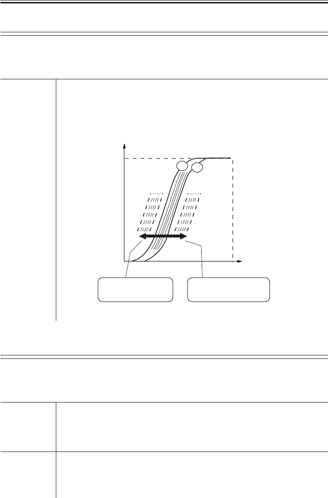
COPYRIGHT
©
2001 CANON INC. 2000 2000 2000 2000 CANON iR2200/iR2800/iR3300 REV.0 MAR. 2001
CHAPTER 5 SERVICE MODE
5-50 T
<DENS>
Use it to fine-adjust the copy density auto correction mechanism.
If you have cleared the RAM on the DC controller PCB and replaced the PCB, be sure to
enter the settings indicated on the service label.
DENS-ADJ Use it to correct the density of images (copier/printer).
Use it to correct the F-value table if the image is foggy or the high-density
area is fuzzy.
Range of 1 to 9; default: 5
adjustment
F05-401-07
COPIER>ADJUST>BLANK
<BLANK>
Use it to adjust the non-image width.
If you have cleared the RAM on the DC controller PCB and replaced the PCB, be sure to
enter the settings indicated on the service label.
BLANK-T Use it to enter the leading edge non-image width.
Range of -100 to +100
adjustment
BLANK-B Use it to enter the trailing edge non-image width.
Range of -100 to +100
adjustment
White
Copy density
Black Original density White
F9 F1
A lower setting
decreases fogging. A higher setting
decreases fuzziness.
COPIER>ADJUST>DENS

COPYRIGHT
©
2001 CANON INC. 2000 2000 2000 2000 CANON iR2200/iR2800/iR3300 REV.0 MAR. 2001
CHAPTER 5 SERVICE MODE
5-51 T
<HV-PRI>
Use it to adjust the output of the primary charging assembly.
If you have cleared the RAM on the DC controller PCB and replaced the PCB, be sure to
enter the setting indicated on the service label.
P-DC Use it to enter the adjustment value for the primary charging DC compo-
nent of the image area.
Range of 0 to 255
adjustment
Caution
P-AC Use it to enter the adjustment value for the primary charging AC component
of the image area.
Range of 0 to 255
adjustment
AGS-GAIN Use it to adjust the gain adjustment value for the photosensitive drum resis-
tance detection control (APVC) mechanism.
Caution If you have replaced the composite power supply PCB, be sure to enter the
settings indicated on the label attached to the new PCB (case).
Range of 0 to 255
adjustment
AGS-OFST Use it to enter the offset adjustment value for the photosensitive drum resis-
tance detection control (APVC) mechanism.
Caution If you have replaced the composite power supply PCB, be sure to enter the
settings indicated on the label attached to the new PCB (case).
Range of 0 to 255
adjustment
COPIER>ADJUST>HV-PRI

COPYRIGHT
©
2001 CANON INC. 2000 2000 2000 2000 CANON iR2200/iR2800/iR3300 REV.0 MAR. 2001
CHAPTER 5 SERVICE MODE
5-52 T
OFST1-DC Use it to enter the adjustment value for the primary charging DC offset 1.
Caution If you have replaced the composite power supply PCB, be sure to enter the
settings indicated on the label attached to the new PCB (case).
Range of 0 to 255 (a lower setting generates lighter images)
adjustment
OFST1-AC Use it to enter the adjustment value for the primary charging AC offset 1.
Caution If you have replaced the composite power supply PCB, be sure to enter the
settings indicated on the label attached to the new PCB (case).
Range of 0 to 255
adjustment
P-AC2 Use it to enter the adjustment value for the primary charging AC component
2 for the image area.
Range of 0 to 255
adjustment
P-AC3 Use it to enter the adjustment value for the primary charging AC component
3 for the image area.
Range of 0 to 255
adjustment
COPIER>ADJUST>HV-PRI

COPYRIGHT
©
2001 CANON INC. 2000 2000 2000 2000 CANON iR2200/iR2800/iR3300 REV.0 MAR. 2001
CHAPTER 5 SERVICE MODE
5-53 T
<HV-TR>
User it to adjust the output for transfer charging/pre-transfer.
If you have cleared the RAM on the DC controller PCB and replaced the PCB, be sure to
enter the settings indicated on the service label.
TR-N1 Use it to enter the output adjustment value for the transfer charging current
(for plain paper, printing on one side or the 1st side of a double-sided
print).
Range of 0 to 10
adjustment
TR-N2 Use it to enter the output adjustment value for the transfer bias (for plain
paper, the 2nd side of a double-sided print).
Range of 0 to 10
adjustment
TR-OFST Use it to enter the output adjustment offset value for transfer charging cur-
rent.
Range of 0 to 255
adjustment
TR-SPP Use it to enter the output adjustment bias value of thick paper transfer (for
thick paper, printing on one side or printing on the 1st/2nd side of a double-
sided print).
• A higher setting causes stronger effects.
Range of 0 to 10
adjustment
COPIER>ADJUST>HV-TR

COPYRIGHT
©
2001 CANON INC. 2000 2000 2000 2000 CANON iR2200/iR2800/iR3300 REV.0 MAR. 2001
CHAPTER 5 SERVICE MODE
5-54 T
<FEED-ADJ>
Use it to make feeder-related adjustments.
If you have cleared the RAM on the DC controller PCB and replaced the PCB, be sure to
enter the settings indicated on the service label.
REGIST Use it to adjust the timing at which the registration roller clutch goes ON.
• A higher setting delays the timing at which the registration roller clutch
goes ON, thereby decreasing the leading edge margin.
Range of -600 to +600 (in mm)
adjustment
ADJ-REFE Use it to adjust the horizontal registration for re-pickup.
• If the image is displaced to the front, increase the setting.
Range of -50 to +50 (in mm)
adjustment
ARCH Use it to adjust the degree of arching on the registration roller.
• Use it to fine-adjust the degree of arching paper is caused to make
against the registration roller.
Range of -100 to +200 (in 0.1 mm); default: 80
adjustment
COPIER>ADJUST>CST-ADJ
<CST-ADJ>
Use it to make cassette/manual feeder-related adjustments.
If you have cleared the RAM on the DC controller PCB and replaced the PCB, be user to
enter the settings indicated on the service label. If you have replaced the paper width detect-
ing VR or want to enter settings newly, be sure to execute FUNCTION>CST in service
mode.
MF-A4R Use it to enter the paper width basic value for the multifeeder tray (A4R).
Range of 0 to 1024
adjustment
MF-A6R Use it to enter the paper width basic value for the multifeeder tray (A6R).
Range of 0 to 1024
adjustment
COPIER>ADJUST>FEED-ADJ

COPYRIGHT
©
2001 CANON INC. 2000 2000 2000 2000 CANON iR2200/iR2800/iR3300 REV.0 MAR. 2001
CHAPTER 5 SERVICE MODE
5-55 T
MF-A4 Use it to enter the paper width basic value for the multifeeder tray (A4).
Range of 0 to 1024
adjustment
COPIER>ADJUST>FIXING
<FIXING>
Use it to make fixing-relating adjustments.
If you have cleared the RAM on the DC controller PCB and replaced the PCB, be sure to
enter the settings indicated on the service label.
FX-FL-TH Use it to enter the fine-adjusted value for the fixing film speed for thick pa-
per.
• Use it to make fine-adjustments in relation to the target control speed of
the fixing film when thick paper is selected.
Range of -3 to +3 (in msec; default: 0)
adjustment
FX-FL-SP Use it to enter the fine adjustment value for the fixing film when plain pa-
per is selected.
• Use it to fine-adjust the target control speed for the fixing film when
plain paper is selected.
Range of -3 to +3 (in msec; default: 0)
adjustment
COPIER>ADJUST>CST-ADJ

COPYRIGHT
©
2001 CANON INC. 2000 2000 2000 2000 CANON iR2200/iR2800/iR3300 REV.0 MAR. 2001
CHAPTER 5 SERVICE MODE
5-56 T
<MISC>
Use it to make other adjustments.
If you have cleared the RAM on the DC controller PCB and replaced the PCB, be sure to
enter the settings indicated on the service label.
C1-ADJ-Y Use it to enter the cassette 1 horizontal registration adjustment value.
• Enter a value in relation to the registered value for the laser write start
position for paper picked up from the cassette 1.
Range of -32 to + 32 (in steps; ‘1’ step being 0.16 mm)
adjustment
C2-ADJ-Y Use it to enter the cassette 2 horizontal registration adjustment value.
• Enter a value in relation to the registered value for the laser write start
position for paper picked up from the cassette 2.
Range of -32 to +32 (in steps; ‘1’ step being 0.16mm)
adjustment
C3-ADJ-Y Use it to enter the cassette 3 horizontal registration adjustment value.
• Enter a value in relation to the registered value for the laser write start
position for paper picked up from the cassette 3.
Range of -32 to +32 (in steps; ‘1’ step being 0.16mm)
adjustment
C4-ADJ-Y Use it to enter the cassette 4 horizontal registration adjustment value.
• Enter a value in relation to the registered value for the laser write start
position for paper picked up from the cassette 4.
Range of -32 to +32 (in steps; ‘1’ step being 0.16mm)
adjustment
MF-ADJ-Y Use it to enter the horizontal registration adjustment value for the
multifeeder.
• Use it to enter a laser write start position value in relation to the regis-
tered value for paper picked up from the multifeeder tray.
Range of -32 to +32 (in steps; ‘1’ step being 0.16mm)
adjustment
COPIER>ADJUST>MISC

COPYRIGHT
©
2001 CANON INC. 2000 2000 2000 2000 CANON iR2200/iR2800/iR3300 REV.0 MAR. 2001
CHAPTER 5 SERVICE MODE
5-57 T
DK-ADJ-Y Use it to enter the horizontal registration adjustment value for the paper
deck.
• Use it to enter a laser write position value in relation to the registered
value for paper picked up from the paper deck.
Range of -32 to +32 (in steps; 1 step being 0.16 mm)
adjustment
FRAME-X Use it to enter a zoom fine-adjustment value (sub scanning direction).
• Use it to enter an extra length of the image in sub scanning direction in
relation to the registered value.
Range of -50 to +50 (-1% to +1%)
adjustment
FRAME-Y Use it to enter the zoom fine-adjustment value (main scanning direction).
• Use it to enter an extra length for the image in main scanning direction
in relation to the register value.
Range of -50 to +50 (-1% to +1%)
adjustment
IMG-DLY Use it to enter a fine-adjustment value (sub scanning direction) for image
delay.
• Use it to make fine adjustments for the length of image delay in sub
scanning direction when sending image data from the main controller PCB
to the DC controller PCB.
Range of -20 to +20 (in 0.1 mm)
adjustment
COPIER>ADJUST>MISC

COPYRIGHT
©
2001 CANON INC. 2000 2000 2000 2000 CANON iR2200/iR2800/iR3300 REV.0 MAR. 2001
CHAPTER 5 SERVICE MODE
5-58 T
4.2 FEEDER
DOCST Use it to adjust the original leading edge registration when the ADF is used.
• A higher setting decreases the leading edge margin.
• The data is stored on the ADF controller PCB.
Range of -10 to +10 (in 0.5 mm)
adjustment Using the Mode
1) Make a print of the Test Chart, and check the position of the image.
2) Select the item, and change the setting to adjust.
3) Press the OK key.
4) Make a print of the Test Chart once again, and check to make sure that
the image position is as indicated.
F05-402-01
LA-SPEED Use it to adjust the original feed speed in stream reading mode with the
ADF in use.
• A higher setting increases the speed.
• The data is stored on the ADF controller PCB.
Range of -30 to +30 (in 0.1%)
adjustment
Feed direction
Higher setting Lower setting
Print image
FEEDER>ADJUST
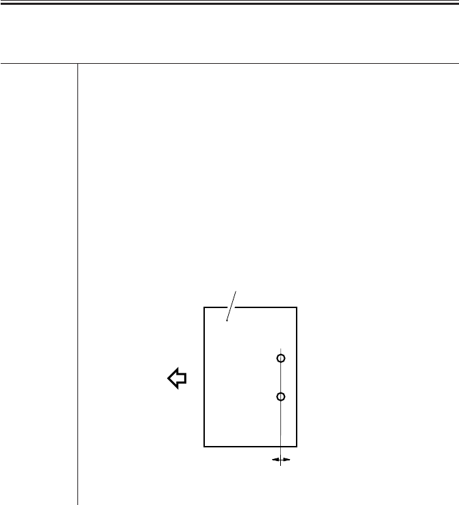
COPYRIGHT
©
2001 CANON INC. 2000 2000 2000 2000 CANON iR2200/iR2800/iR3300 REV.0 MAR. 2001
CHAPTER 5 SERVICE MODE
5-59 T
4.3 SORTER
PNCH-HLE Use it to adjust the punch hole position (paper feed direction) when the
puncher unit is in use.
• A higher setting shifts the punch hole toward the leading edge of paper
(middle of paper).
Range of -3 to +3 (in mm)
adjustment Using the Mode
1) Make a print of the Test Chart, and check the position of the hole.
2) Select the item, and change the setting to adjust.
3) Press the OK key.
4) Make a print of the Test Chart once again, and check to make sure that
the hole position is as indicated.
F05-403-01
Feed direction
Higher setting Lower setting
Paper
SORTER>ADJUST
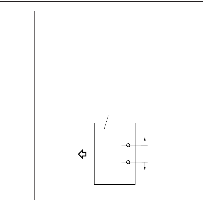
COPYRIGHT
©
2001 CANON INC. 2000 2000 2000 2000 CANON iR2200/iR2800/iR3300 REV.0 MAR. 2001
CHAPTER 5 SERVICE MODE
5-60 T
PNCH-Y Use it to adjust the punch hole position (front/rear of paper) when the
puncher unit is in use.
• A higher setting shifts the punch hole toward the front of paper.
Range of -5 to +5 (in mm)
adjustment Using the Mode
1) Make a print of the Test Chart, and check the position of the hole.
2) Select the item, and change the setting to adjust.
3) Press the OK key.
4) Make a print of the Test Chart once again, and check to make sure that
the hole position is as indicated.
F05-403-02
Feed direction
Higher setting
Lower setting
Paper
SORTER>ADJUST
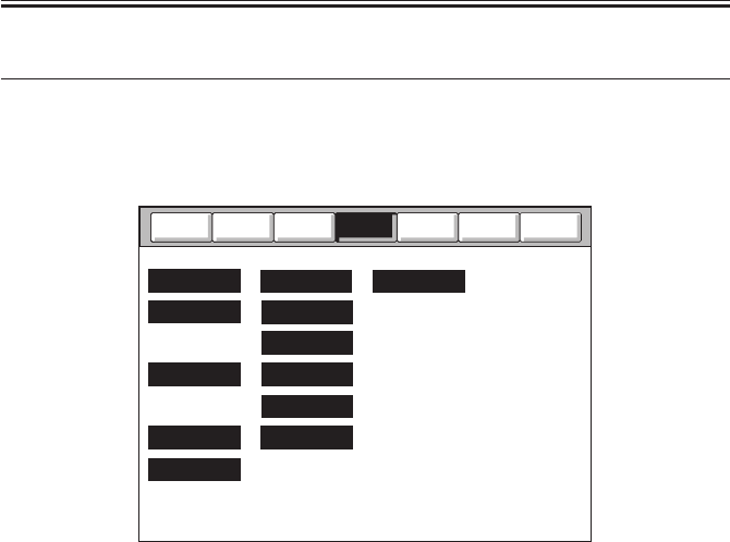
COPYRIGHT
©
2001 CANON INC. 2000 2000 2000 2000 CANON iR2200/iR2800/iR3300 REV.0 MAR. 2001
CHAPTER 5 SERVICE MODE
5-61 T
5 FUNCTION Operation/Inspection Mode
5.1 COPIER
The following screen will appear in response to COPIER>FUNCTION; lists of items fol-
low:
F05-501-01
Counter
Test
Option
I/O
Display
CCD
INSTALL
DENS
FIXING SYSTEM
MISC-P
CST
DPC
MISC-R
CLEAR
PART-CHK
PANEL
Adjust
Function

COPYRIGHT
©
2001 CANON INC. 2000 2000 2000 2000 CANON iR2200/iR2800/iR3300 REV.0 MAR. 2001
CHAPTER 5 SERVICE MODE
5-62 T
<INSTALL>
Use it as part of installation work.
TONER-S Use it to stir the toner inside the developing assembly.
Caution • Check to make sure that the developing assembly is securely mounted
before pressing the OK key.
• Do not execute any operation. (The Stop key may be pressed.)
Using the Mode
1) Select <TONER-S> to highlight; then, press the OK key.
2) The machine stirs toner (about 4 min), during which time a count-down
is indicated to the right of <TONER-S> from 240 to 0.
3) The machine automatically stops after stirring toner.
STRD-POS Use it to execute automatic adjustment of the CCD read position in stream
mode.
Caution • Execute this mode when installing the ADF or if you have removed and
then installed the ADF once again.
Using the Mode
1) Select <STRD-POS> to highlight; then, press the OK key.
• The machine executes automatic adjustment.
2) The machine stops operation automatically after adjustment.
3) The settings under COPIER>ADJUST>ADJ-XY>STRD-POS is up-
dated. Record the new settings to the service label.
CARD Use it when installing the card reader.
Using the Mode
Enter the number of the card to use. 1 to 2701 (default: 1; as many as 300
cards may be used starting with the entered number)
Use it to initialize card control information:
• initializing the card names (group ID; starting with the entered number).
• initializing ID numbers for cards.
COPIER>FUNCTION>INSTALL

COPYRIGHT
©
2001 CANON INC. 2000 2000 2000 2000 CANON iR2200/iR2800/iR3300 REV.0 MAR. 2001
CHAPTER 5 SERVICE MODE
5-63 T
<CCD>
Use it to execute CCD/shading-related automatic adjustment.
CCD-ADJ Use it to execute automatic adjustment of the CCD.
Caution • Execute the mode if you have replaced any of the following: CCD unit,
scanning lamp, inverter PCB, copyboard glass (standard white plate).
• Use the whitest of all papers used by the user (excluding color print pa-
per).
Using the Mode
1) Place ten or more sheets of standard white paper on the copyboard glass.
2) Select <CCD-ADJ> to highlight, and press the OK key.
3) The machine executes automatic adjustment (about 15 sec), during
which time <SERVICE> appears in the upper right of the screen.
4) During the operation, the scanning lamp will go ON; at the end of the
automatic adjustment, the screen will indicate <OK!>.
5) All items under COPIER>ADJUST>CCD are updated. Record the new
settings on the service label.
F05-501-02
(rear)
Standard white paper
COPIER>FUNCTION>CCD
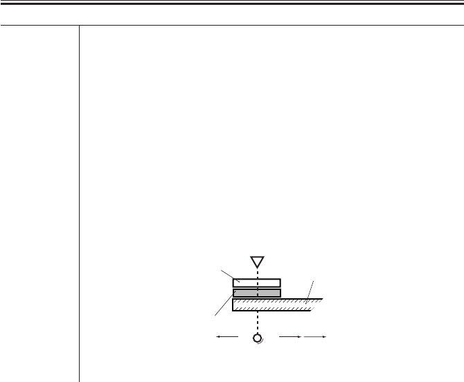
COPYRIGHT
©
2001 CANON INC. 2000 2000 2000 2000 CANON iR2200/iR2800/iR3300 REV.0 MAR. 2001
CHAPTER 5 SERVICE MODE
5-64 T
SHDG-POS Use it to enter data for changing the position of measurement on the stan-
dard white plate used for shading correction.
Range of 240 to 320 (a multiple of 8 causes a shift of about 0.17 mm)
adjustment
Caution • Execute this mode if a white line still appears after executing
COPIER>FUNCTION>CCD>SH-PS-ST or after cleaning the scanner
mechanisms.
• After entering a setting and executing
COPIER>FUNCTION>CCD>SH-PS-ST, check to make sure that ‘OK’ is
indicted. Thereafter, make a test print to be user that no white line is found
in its halftone area.
F05-501-03
Vertical
size plate
Standard white plate
Lower setting
Higher setting
Copyboard glass
Shading
position
COPIER>FUNCTION>CCD

COPYRIGHT
©
2001 CANON INC. 2000 2000 2000 2000 CANON iR2200/iR2800/iR3300 REV.0 MAR. 2001
CHAPTER 5 SERVICE MODE
5-65 T
SH-PS-ST Use it to execute optimum position auto adjustment for the standard white
plate for shading correction.
Caution • You must execute COPIER>FUNCTION>CCD>CCD-ADJ before ex-
ecuting this move.
• Execute this mode if you have replaced the copyboard glass (standard
white plate) or a white line is noted in halftone areas.
Using the Mode
1) Clean the back of the copyboard glass.
2) Open the ADF (copyboard cover).
3) Select <SH-PS-ST> to highlight, and press the OK key.
4) The machine executes automatic adjustment (about 10 sec).
5) When done, the machine stops automatically indicating the result (OK/
NG).
• If ‘NG’ is indicated, perform the following, and execute the mode once
again:
a. Is the ADF (copyboard cover) open?
b Is the copyboard glass mounted correctly?
c. Is the standard white plate (attached to the copyboard glass) normal?
d. Does the scanning lamp go ON?
6) The items under COPIER>ADJUST>ADJ-XY and ADJ-S are updated.
Record the new settings on the service label.
COPIER>FUNCTION>CCD

COPYRIGHT
©
2001 CANON INC. 2000 2000 2000 2000 CANON iR2200/iR2800/iR3300 REV.0 MAR. 2001
CHAPTER 5 SERVICE MODE
5-66 T
EGGN-POS Use it to execute automatic adjustment of the edge gain correction for the
CCD. (The edge gain correction of the CCD is effective only when the ADF
is in use.)
Caution • If you have replaced the CCD unit, be sure to execute the following
first: COPIER>FUNCTION>CCD>CCD-ADJ.
• Execute this mode if you have replaced any of the following: CCD unit,
No. 1 mirror base, No. 2 mirror base.
Using the Mode
1) Open the ADF (copyboard cover).
2) Select <EGGN-POS> to highlight, and press the OK key.
3) The machine executes automatic adjustment (about 1 sec).
4) When done, the machine stops automatically, and indicates the result
(OK/NG).
• If ‘NG’ is indicated, perform the following, and execute this mode once
again:
a. Is the ADF (copyboard cover) open?
b. Is the read glass mounted correctly?
c. Is the edge gain correction plate (attached to the read glass) normal?
d. Does the scanning lamp go ON?
5) The items under COPIER>ADJUST>CCD>EGGN-ST and EGGN-
END are updated. Record the new settings on the service label.
F05-501-04
Edge gain correction plate
Copyboard glass
(front)
Read glass
COPIER>FUNCTION>CCD
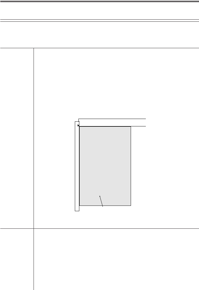
COPYRIGHT
©
2001 CANON INC. 2000 2000 2000 2000 CANON iR2200/iR2800/iR3300 REV.0 MAR. 2001
CHAPTER 5 SERVICE MODE
5-67 T
<DENS>
Use it to execute automatic density adjustment.
Execute this mode after shading correction, and be sure to execute all of the following in
sequence: WHITE-ME, PD-DENS, PD-ME.
WHITE-ME Use it to execute automatic density correction of the white level.
Using the Mode
1) Place standard white paper (10 sheets or more; of papers commonly
used by the user) on the copyboard glass.
2) Select <WHITE-ME> to highlight, and press the OK key.
3) The scanning lamp makes a single scan, and the machine ends opera-
tion.
F05-501-05
PD-DENS Use it to generate a print pattern for density auto adjustment for text mode.
Caution • The machine uses the PD method for binary processing in text mode; be
sure to use this mode as automatic density adjustment.
Using the Mode
1) Select <PD-DENS> to highlight, and press the OK key.
2) See that the machine uses cassette 2 as the source of paper and generate
a 17-gradation print pattern. The print pattern will be used when executing
<PD-ME>.
(rear)
Standard white paper
COPIER>FUNCTION>DENS
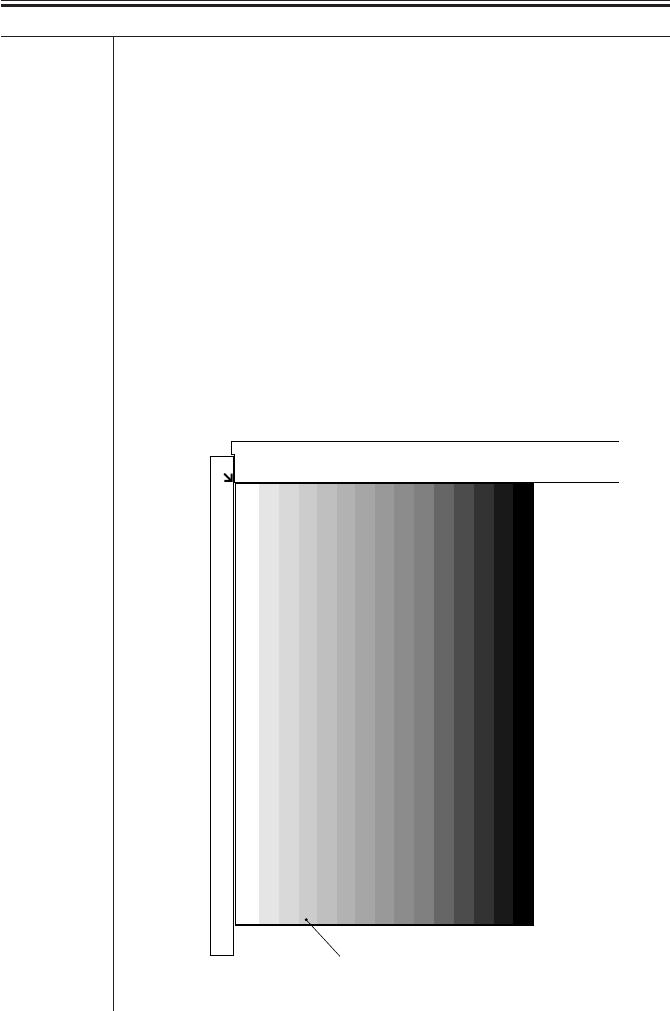
COPYRIGHT
©
2001 CANON INC. 2000 2000 2000 2000 CANON iR2200/iR2800/iR3300 REV.0 MAR. 2001
CHAPTER 5 SERVICE MODE
5-68 T
PD-ME Use it to execute automatic density correction for text mode (to read PD-
DENS output).
Using the Mode
1) While keeping the following in mind, place the PD-DENS output on the
copyboard glass as indicated:
• The printed side must face down.
• The whiter side (lighter; of the 17 gradations) must face the vertical size
plate.
• The output must be placed in relation to the index in the left rear of the
copyboard glass.
2) Select <PD-ME> to highlight, and press the OK key.
3) The scanning lamp goes ON and OFF 13 times, making as many scans
automatically.
• If ‘OK’ is indicated, end the work.
• If ‘NG’ is indicated, discussed under “Standards and Adjustments” in
Chapter 3.
F05-501-06
Place it so that
the printed side
faces down.
PD-DENS output
COPIER>FUNCTION>DENS

COPYRIGHT
©
2001 CANON INC. 2000 2000 2000 2000 CANON iR2200/iR2800/iR3300 REV.0 MAR. 2001
CHAPTER 5 SERVICE MODE
5-69 T
<DPC>
Use it to execute potential-related operations.
D-GAMMA Use it to execute photosensitive drum resistance measurement control
(APVC).
Caution Use this mode only for the following; do not rely on this mode unless nec-
essary:
• When making adjustments after replacing the drum unit.
• When isolating the cause when copy density automatic adjustment (PD-
ME) ends in NG.
• When obtaining an idea of the life of the drum.
Using the Mode
1) Select the item, and press the OK key.
2) The machine generates a blank copy and ends automatically.
3) See that the machine indicates the result of measurement under
DISPLAY>HV-STS>PRIMARY.
COPIER>FUNCTION>CST
<CST>
Use it to execute size automatic adjustment for the multifeeder.
MF-A4R
MF-A6R
MF-A4 Use it to adjust the paper width basic value for the multifeeder.
A4R: width: 210 mm, A6R width: 105 mm, A4 width: 297 mm
Caution To make fine-adjustments after entering the basic value, use ADJUST>CST-
ADJ>MF-A4R, MF-A6R, MF-A4.
Using the Mode
1) Place A4R paper in the multifeeder, and adjust the side guide to A4R.
2) Select <MF-A4R> to highlight, and press the OK key.
• The machine executes automatic adjustment and stores the value.
3) Likewise, perform steps 1. and 2. for A6R and A4.
COPIER>FUNCTION>DPC
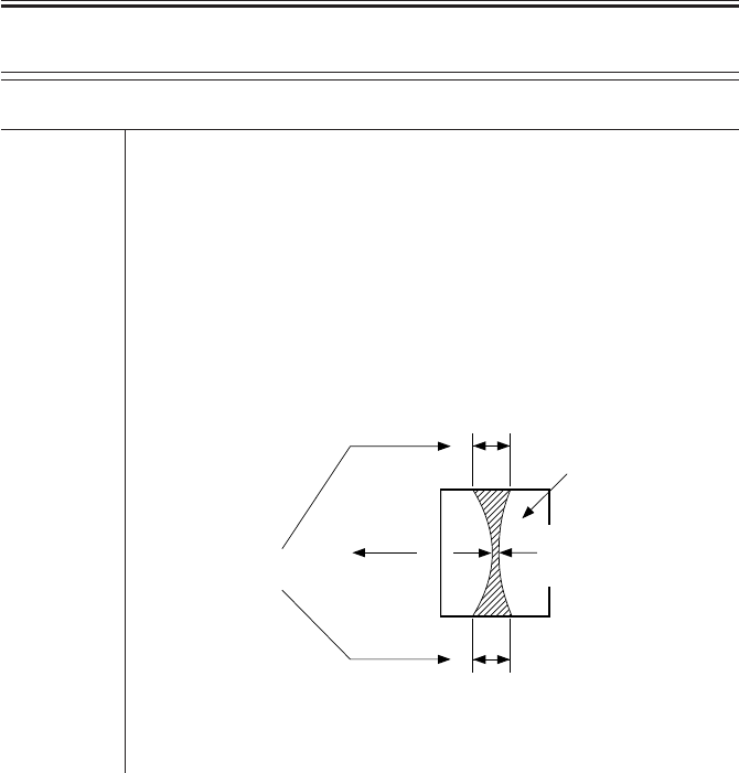
COPYRIGHT
©
2001 CANON INC. 2000 2000 2000 2000 CANON iR2200/iR2800/iR3300 REV.0 MAR. 2001
CHAPTER 5 SERVICE MODE
5-70 T
<FIXING>
Use it to execute fixing assembly-related automatic adjustments.
NIP-CHK Use it to obtain output for automatic measurement of the fixing nip width.
Using the Mode
1) Make a solid black print in A4/LTR.
2) Make about 20 A4/LTR prints of the Test Sheet.
3) Place the A4/LTR solid black output obtained in step 1. in the manual
feed tray with the printed side facing down.
4) Select <NIP-CHK>, and press the OK key.
• After pickup, the paper will stop between the fixing rollers and then de-
livered in about 20 sec.
5) Measure the width indicated in the diagram.
F05-501-07
Caution a and b are points 10 mm from both ends of the paper.
Paper feed
direction
Standard
a - c = 0.5 mm or less
Standard:
5.5 ± 0.3 mm
c
a
b
Middle
of paper
COPIER>FUNCTION>FIXING

COPYRIGHT
©
2001 CANON INC. 2000 2000 2000 2000 CANON iR2200/iR2800/iR3300 REV.0 MAR. 2001
CHAPTER 5 SERVICE MODE
5-71 T
<PANEL>
Use it to check the control panel.
LCD-CHK Use it to check the touch panel for missing dots.
Using the Mode
1) Select <LCD-CHK> to highlight, and press the OK key. The entire face
of the touch panel will go ON and remain white for several seconds and
then blue for several seconds.
2) Press the Stop key to end the operation.
LED-CHK Use it to check the LEDs of the control panel for activation.
Using the Mode
1) Select <LED-CHK> to highlight, and press the OK key so that the
LEDs will go ON in sequence.
2) Select <LED-OFF> to end the operation.
LED-OFF Use it to end a check on the LEDs of the control panel.
Using the Mode
1) Select <LED-OFF> to end the operation.
KEY-CHK Use it to check the key inputs.
Using the Mode
1) Select <KEY-CHK> so that the numbers/names of the input keys will
appear.
2) Press a key to check. If normal, its corresponding notation will appear
on the touch panel. (T05-501-01)
3) Select <KEY-CHK> once again to end the key input check.
TOUCHCHK Use it to adjust the coordinates on the touch panel.
Caution • Use it to match points (presses) on the touch panel and the LCD coordi-
nates.
• Execute this mode if you have replaced the LCD.
Using the Mode
1) Select <TOUCHCHK> to highlight, and press the OK key.
2) Press the nine +’s that paper on the touch panel in sequence.
3) The machine ends operation when all nine +’s been pressed.
COPIER>FUNCTION>PANEL

COPYRIGHT
©
2001 CANON INC. 2000 2000 2000 2000 CANON iR2200/iR2800/iR3300 REV.0 MAR. 2001
CHAPTER 5 SERVICE MODE
5-72 T
Input Keys/Indications
T05-501-01
COPIER>FUNCTION>PART-CHK
<PART-CHK>
Use it to check the operation of a specific load.
CL Use it to select a clutch whose operation you want to check.
Using the Mode
1) Select the item.
2) Enter the code (T05-501-02) of the clutch using the keypad.
3) Press the OK key.
CL-ON Use it to check the operation of the clutch.
Using the Mode
1) Select the item, and press the OK key.
• ON → OFF for 10 sec → ON → OFF for 10 sec → ON → OFF
MTR Use it to select a motor whose operation you want to check.
Using the Mode
1) Select the item.
2) Enter the code (T05-501-03) of the motor using the keypad.
3) Press the OK key.
Key name Indication on screen
Counter Check BILL
Copy COPY
Fax FAX
Mail Box PB
Scan OTHER
O to 9, #, * O to 9, #, *
Clear (C) CLEAR
Key name Indication on screen
ID ID
Additional Functions USER
Start START
Stop STOP
Reset RESET
Interrupt INTERRUPT
Guide ?
COPIER>FUNCTION>PANEL

COPYRIGHT
©
2001 CANON INC. 2000 2000 2000 2000 CANON iR2200/iR2800/iR3300 REV.0 MAR. 2001
CHAPTER 5 SERVICE MODE
5-73 T
MTR-ON Use it to check the motor.
Using the Mode
1) Select the item, and press the OK key.
• ON for 20 sec → OFF
• For the duplex horizontal registration motor, ON for 10 sec → OFF
SL Use it to select a solenoid whose operation you want to check.
Using the Mode
1) Select the item.
2) Enter the code (T05-501-04) of the solenoid using the keypad.
3) Press the OK key.
SL-ON Use this mode to check the operation of a solenoid.
Using the Mode
1) Select the item and press the OK key.
• ON → OFF for 5 sec → ON → OFF for 5 sec → ON → OFF
Codes and Clutches
T05-501-02
Code Name
1 Vertical path clutch (CL1)
2 Multifeeder pickup clutch (CL2)
3 Developing clutch (CL3)
4 Vertical path roller clutch (CL1C)
5 Deck feeding clutch (CL1D)
6 Deck pickup clutch (CL2D)
COPIER>FUNCTION>PART-CHK

COPYRIGHT
©
2001 CANON INC. 2000 2000 2000 2000 CANON iR2200/iR2800/iR3300 REV.0 MAR. 2001
CHAPTER 5 SERVICE MODE
5-74 T
Codes and Motors
T05-501-03
Codes and Solenoids
T05-501-04
Code Name
1 Main motor (M1)
2 Fixing motor (M4)
3 Pickup motor (M2)
4 Duplex motor (M6)
5 Delivery motor (M5)
6 2-way delivery outlet motor (M8B)/
Relay delivery motor (M7Z)
7 2-way delivery inlet motor (M7B)
Code Name
8 Horizontal registration sensor shift
motor (M3)
9 Registration motor (M9)
10 Laser scanner motor (M10)
11 Pedestal main motor (M1C)
12 Cassette pickup motor (M2C)
13 Deck main motor (M1D)
14 Deck lifter motor (M2D)
Code Name
1 Pickup DOWN solenoid (SL1)
2 2-way delivery solenoid (SL3B)/
Relay delivery solenoid (SL3Z)
3 Charging roller solenoid (SL6)
4 Multifeeder holding plate
releasing solenoid (SL5)
Code Name
5 ---
6 Pickup roller DOWN solenoid (SL1C)
7 Deck pickup roller releasing solenoid
(SL1D)
8 Deck open solenoid (SL2D)
COPIER>FUNCTION>PART-CHK

COPYRIGHT
©
2001 CANON INC. 2000 2000 2000 2000 CANON iR2200/iR2800/iR3300 REV.0 MAR. 2001
CHAPTER 5 SERVICE MODE
5-75 T
<CLEAR>
Use it to clear the RAM, jam history, or error code history.
The effect does not take place unless the main power switch has been turned off and then
on.
ERR Use this mode to clear an error code: E000, E001, E002, E003, E004,
E032, E717.
Using the Mode
1) Select <ERR> to highlight, and press the OK key.
2) Turn off and then on the main power switch.
DC-CON Use it to clear the RAM on the DC controller PCB.
Using the Mode
1) Select <DC-CON> to highlight, and press the OK key.
2) Turn off and then on the main power switch.
R-CON Use it to clear the RAM on the reader controller PCB.
Using the Mode
1) Select <R-CON> to highlight, and press the OK key.
2) Turn off and then on the main power switch.
SERVICE Use it to clear the backup data for the service mode (COPIER>OPTION).
Using the Mode
1) Select <SERVICE> to highlight, and press the OK key.
2) Turn off and then on the main power switch.
JAM-HIST Use it to clear the jam history.
Using the Mode
1) Select <JAM-HSIT> to highlight, and press the OK key.
2) Turn off and then on the main power switch.
ERR-HIST Use it to clear the error code history.
Using the Mode
1) Select <ERR-HITS> to highlight, and press the OK key.
2) Turn off and then on the main power switch.
E345-CLR ---
COPIER>FUNCTION>CLEAR

COPYRIGHT
©
2001 CANON INC. 2000 2000 2000 2000 CANON iR2200/iR2800/iR3300 REV.0 MAR. 2001
CHAPTER 5 SERVICE MODE
5-76 T
E355-CLR ---
PWD-CLR Use it to clear the password of the system administrator in user mode.
Using the Mode
1) Select <PWD-CLR> to highlight, and press the OK key.
2) Turn off and then on the main power switch.
ADRS-BK Use it to clear the address book data.
Using the Mode
1) Select <ADRS-BK> to highlight, and press the OK key.
2) Turn off and then on the main power switch.
CNT-MCON Use it to clear the counters for servicing on the main controller PCB.
Using the Mode
1) Select <CNT-MCON> to highlight, and press the OK key.
2) Turn off and then on the main power switch.
CNT-DCON Use it to clear the counter for servicing on the DC controller PCB.
Using the Mode
1) Select <CNT-DCON> to highlight, and press the OK key.
2) Turn off and then on the main power switch.
MMI Use it to clear the backup data for the user mode settings (specifications, ID
mode, group ID, mode memory, etc.).
Using the Mode
1) Select <MMI> to highlight, and press the OK key
2) Turn off and then on the main power switch.
CARD Use it to clear the card (group) ID-related data.
Using the Mode
1) Select <CARD> to highlight, and press the OK key.
2) Turn off and then on the main power switch.
ALARM Use it to clear the alarm log.
Using the Mode
1) Select <ALARM> to highlight, and press the OK key.
2) Turn off and then on the main power switch.
COPIER>FUNCTION>CLEAR

COPYRIGHT
©
2001 CANON INC. 2000 2000 2000 2000 CANON iR2200/iR2800/iR3300 REV.0 MAR. 2001
CHAPTER 5 SERVICE MODE
5-77 T
<MISC-R>
Checking reader unit-related operations.
SCANLAMP Use it to check the scanning lamp for activation.
Using the Mode
1) Select <SCANLAMP> to highlight, and press the OK key.
2) The scanning lamp goes ON.
3) Press the Stop key to turn off the lamp.
COPIER>FUNCTION>MISC-R

COPYRIGHT
©
2001 CANON INC. 2000 2000 2000 2000 CANON iR2200/iR2800/iR3300 REV.0 MAR. 2001
CHAPTER 5 SERVICE MODE
5-78 T
<MISC-P>
Use it to check the operation of the printer unit.
P-PRINT Use it to print out the contents of service mode (ADJUST, OPTION,
COUNTER).
Caution • It may take several dozens of seconds to print out the list.
Using the Mode
1) Select <P-PRINT> to highlight, and press the OK key.
2) The machine will deliver a total of three lists face down.
Source of Paper
• If a specific paper is selected on the basic screen, the corresponding
source will be used.
• If auto paper selection is used, the topmost cassette will be used as the
source of paper.
KEY-HIST Use it to print out the history of key inputs made from the control panel.
Using the Mode
1) Select <KEY-HITS> to highlight, and press the OK key.
• The machine generates a key input history.
AA:AA BBBB CCCC xxxxxxxx
AA time at which the key is pressed
BB if number: soft key number
HARD: hard key
SOFT: soft key
ONET: one touch key
CC key type RESET: reset key
START: start key
GUIDE: guide key
USER MODE: additional function key
FNC_COPY: ‘copy’ key within extended keys
FNC_FAX: ‘fax’ key within extended keys
POWER_MIMI: control panel power key
xxxxxxxx function value
COPIER>FUNCTION>MISC-P

COPYRIGHT
©
2001 CANON INC. 2000 2000 2000 2000 CANON iR2200/iR2800/iR3300 REV.0 MAR. 2001
CHAPTER 5 SERVICE MODE
5-79 T
HIST-PRT Use it to print out the jam history and the error history stored for service
mode.
Using the Mode
1) Select the item, and press the OK key.
2) The machine prints put the jam history and the error history.
USER-PRT Use it to print out the user mode settings from service mode.
Using the Mode
1) Select the item, and press the OK key.
2) The machine prints out a list of user mode settings.
C1-ADJ-Y Use it to execute cassette 1 horizontal registration automatic adjustment.
Using the Mode
1) Select the item, and press the OK key.
2) The machine prints a halftone PG image on paper from cassette 1. (At
the same time, the horizontal registration sensor measures the displacement,
and stores the result as back-up data.)
C2-ADJ-Y Use into to execute cassette 2 horizontal registration automatic adjustment.
Using the Mode
1) Select the item, and press the OK key.
2) The machine prints a halftone PG image on paper from cassette 2. (At
the same time, the horizontal registration sensor measures the displacement,
and stores the result as back-up data.)
C3-ADJ-Y Use it to execute cassette 3 horizontal registration automatic adjustment.
Using the Mode
1) Select the item, an press the OK key.
2) The machine prints a halftone PG image on paper from cassette 3. (At
the same , time, the horizontal registratoin sensor measures the displace-
ment, and stores the result as back-up data.)
C4-ADJ-Y Use it to execute cassette 4 horizontal registration automatic adjustment.
Using the Mode
1) Select the item, and press the OK key.
2) The machine prints a halftone PG image on paper from cassette 4. (At
the same time, the horizontal registratoin sensor measures the displacement,
and stores the result as back-up data.)
COPIER>FUNCTION>MISC-P

COPYRIGHT
©
2001 CANON INC. 2000 2000 2000 2000 CANON iR2200/iR2800/iR3300 REV.0 MAR. 2001
CHAPTER 5 SERVICE MODE
5-80 T
MF-ADJ-Y Use it to execute multifeeder horizontal registration automatic adjustment.
Using the Mode
1) Select the item, and press the OK key.
2) The machine prints a halftone PG image on paper from the multifeeder
tray. (At the same time, the horizontal registration sensor measures the dis-
placement, and stores the result as back-up data.)
DK-ADJ-Y Use it to execute paper deck horizontal registration automatic adjustment.
Using the Mode
1) Select the item, and press the OK key.
2) The machine prints a halftone PG image on paper from the paper deck.
(At the same time, the horizontal registration sensor measures the displace-
ment, and stores the result as back-up data.)
LBL-PRNT Use it to print out a service label.
Using the Mode
1) Put paper in the manual feed tray.
2) Select the item, and press the OK key.
3) The machine prints out a service label.
• The label also indicates the settings of ADJUST and OPTION.
PRE-EXP Use it to check the pre-exposure lamp for activation.
Using the Mode
1) Select the item, and press the OK key.
2) The pre-exposure lamp goes ON and remains ON for several seconds,
and goes OFF automatically.
COPIER>FUNCTION>MISC-P

COPYRIGHT
©
2001 CANON INC. 2000 2000 2000 2000 CANON iR2200/iR2800/iR3300 REV.0 MAR. 2001
CHAPTER 5 SERVICE MODE
5-81 T
<SYSTEM>
Use it to check system-related operations.
DOWNLOAD
Use it to switch to system program download mode.
Caution • Use it to download the system program.
Using the Mode
1) Turn off the machine and the PC.
2) Disconnect the network cable from the machine.
3) Connect the machine and the PC with a bi-Centronics cable.
4) Turn on the PC.
5) Turn on the machine.
6) Select <DOWNLOAD> to highlight, and press the OK key.
7) Use the Service Support Tool to download the data.
8) When done, turn off and then on the main power switch.
CHK-TYPE Use it to select a partition number for HD-CHECK.
Using the Mode
1) Selects the item.
2) Selects a partition number using the keypad (0: check and recover entire
HDD for faulty sectors, 1: image storage area, 2: general file storage area,
3: PDL-related file storage area, 4: firmware storage area).
• A general file refers to the following: user settings data, log data, PDL
spool data, image data.
3) Press the OK key.
HD-CHECK Use it to execute a check and recovery of the partition selection using CHK-
TYPE.
Using the Mode
1) Select the item.
2) Press the OK key.
3) The machine indicates the result (1: OK, 2: NG (hardware), 3: NG (soft-
ware); recovery sensor/alternate sector).
HD-CLEAR Use it to initialize the partition selected using CHK-TYPE.
Caution • If ‘0’ or ‘4’ is selected, the executing will be invalid.
• If’ ‘1’ is selected, the image control data stored in the SRAM area or the
general file storage area will also be initialized.
Using the Mode
1) Select the item.
2) Press the OK key.
COPIER>FUNCTION>SYSTEM
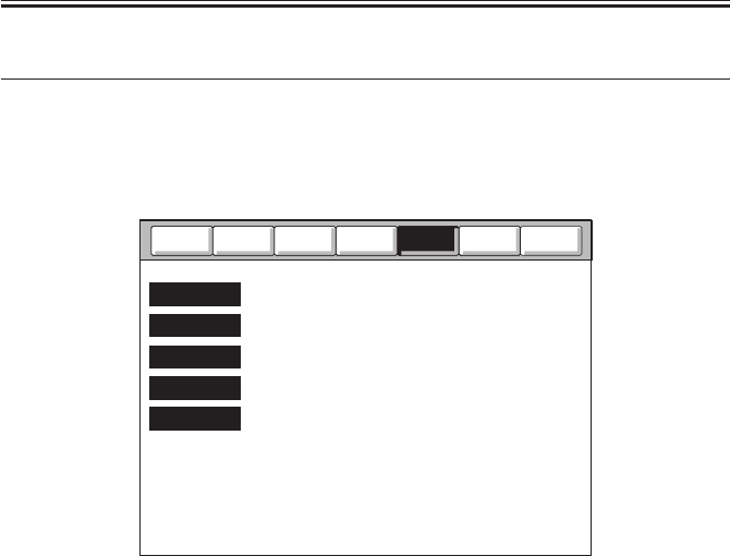
COPYRIGHT
©
2001 CANON INC. 2000 2000 2000 2000 CANON iR2200/iR2800/iR3300 REV.0 MAR. 2001
CHAPTER 5 SERVICE MODE
5-82 T
6 OPTION Machine Settings Mode
6.1 COPIER
The following screen will appear in response to COPIER>OPTION; lists of items will
follow:
F05-601-01
Counter
Test
Function
Adjust
I/O
Display
BODY
USER
CST
ACC
INT-FACE
Option

COPYRIGHT
©
2001 CANON INC. 2000 2000 2000 2000 CANON iR2200/iR2800/iR3300 REV.0 MAR. 2001
CHAPTER 5 SERVICE MODE
5-83 T
BODY
Use it to make machine-related settings.
MODEL-SZ Use it to select the mode of indication by destination and of the ADF origi-
nal size detection.
Settings 0: AB (6R5E), 1: INCH (5R4E), 2: A (3R3E), 3: AB/INCH (6R5E)
FIX-CLN Use it to set fixing cleaning mode:
• During last rotation after the end of printing, the fixing assembly is ro-
tated idly at 1/4 the fixing speed.
Settings 0: no cleaning (default)
1: once per 500 sheets; temperature control at 225 °C , idle rotation for
60 sec
2: once per 200 sheets; temperature control at 225 °C , idle rotation for
60 sec
3: once per 100 sheets; temperature control at 225 °C , idle rotation for
60 sec
4: not used
5: not used
FIX-TEMP Use it to select a fixing control temperature.
Settings 0: disable (default)
1: place priority on productivity; keep control temperature constant: -
10 °C
2: keep control temperature constant: -6 °C
3: keep control temperature constant: -3 °C
4: place priority on fixing; keep control temperature constant: +3 °C
5: keep control temperature constant: +6 °C
6: keep control temperature constant: +10 °C
7: keep control temperature constant: +15 °C
HUM-SW Use it to enable or disable the environment sensor.
Settings 0: auto control by environment sensor
1: fixed mode (for high humidity)
2: fixed mode (for normal humidity)
3: fixed mode (for low humidity)
(In 1, 2, or 3, the move of control does not depend on the environment
sensor.)
COPIER>OPTION>BODY

COPYRIGHT
©
2001 CANON INC. 2000 2000 2000 2000 CANON iR2200/iR2800/iR3300 REV.0 MAR. 2001
CHAPTER 5 SERVICE MODE
5-84 T
SCANSLCT Use it to enable or disable the original size detection mechanism for the
ADF.
• When enabled, the scan size is determined in relation to the original
size.
Settings 0: off (default), 1: on
TRANS-SW Use it to set the transfer charging bias output control method for large-size
paper.
Settings 0: normal (auto mode), 1: constant voltage control (manual mode)
Caution When manual mode is selected, make fine settings in ADJUST>HV-
TR>TR-N1.
PRIAC-SW If an image fault occurs as a result of faulty charging of the drum unit,
change the level of primary charging current to correct the fault. It is effec-
tive if a sandy image (white dots in solid areas) occurs between the installa-
tion of the drum unit to printing of 2000 sheets.
Settings 0: no increase in charging current (default), 1: increase in charging
current
Caution The setting of this mode is cleared (1 → 0) for the following:
• When APVC is executed after installing a new drum unit.
• When COPIER>FUNCTION>D-GAMMA is executed in service mode.
• When the setting is changed in this service mode.
SENS-CNF Use it to set the arrangement of the original sensors.
Settings 0: AB-configuration (default, 1: Inch-configuration, 2: A-configuration)
Caution If you have changed the arrangement of the original sensors, select the ap-
propriate setting to suit the new arrangement.
COPIER>OPTION>BODY

COPYRIGHT
©
2001 CANON INC. 2000 2000 2000 2000 CANON iR2200/iR2800/iR3300 REV.0 MAR. 2001
CHAPTER 5 SERVICE MODE
5-85 T
CONFIG Use it to select any of the multiple pieces of firmware stored on the hard
disk to suit the selected destination and paper size:
Settings XXYYZZAA
XX: country (JP), YY: language (ja), ZZ (00): destination, AA (00): paper
configuration
The method of indication COPIER>DISPLAY>USER>LANGUAGE.
The selections in parentheses are default selections; for the country and the
languages, names are given.
Using the Mode
1) Select <CONFIG>.
2) Select the item to change (to highlight), and press the +/- key.
3) Each press on the +/- key move the selection to the next item.
4) When the desired item is indicated, press the OK key.
5) Turn off and then on the main power switch.
SHARP Use it to change the level of sharpness of soft the image.
• A higher setting makes the image sharper.
Settings 1 to 5 (default: 3)
COTDPC-D for factory.
Settings 0 to 3 (default: 0)
DF-BLINE Use it to enable or disable black line reduction mode (disabling edge em-
phasis) for stream reading.
Caution When enabled, the black lines will be less conspicuous but the edges of the
images will be less crisp.
Settings 0: disable (default)
1: enable
FIX-SMR Use it to set the fixing trail removal mode in a high humidity environment.
Caution When ‘1’ is set, the following will occur:
• The laser intensity will be reduced by 50 V.
• The fixing film control speed is changed from 539 to 535 m/sec.
• The fixing/feeding speed is reduced:
B4: from 14 → 10 ppm
B5R: from 28 → 15 ppm
LGL: from 14 → 10 ppm
A4R,etc.: from 18 → 10 ppm
Settings 0: disable (default)
1: enable
COPIER>OPTION>BODY

COPYRIGHT
©
2001 CANON INC. 2000 2000 2000 2000 CANON iR2200/iR2800/iR3300 REV.0 MAR. 2001
CHAPTER 5 SERVICE MODE
5-86 T
DECRL-FN Use it to enable or disable delivery curl reducing fan.
Settings 0: disable (default)
1: enable
Caution When ‘1’ is selected, the curl reducing fan is rotated for 30 sec after the im-
age leading edge sensor goes ON.
TR-CLN Use it to enable or disable transfer charging roller cleaning enhancement
mode.
Settings 0: disable (default)
1: enable
Caution Make sure that the transfer output between sheets for single-sided printing
is set to cleaning bias output.
FAN-EXTN Use it to enable or disable the fan extension mode at the end of a job.
Settings 0: disable (default)
1: enable
Caution Use it to drive all fans for 5 min after the end of a print job received in sleep
mode.
COPIER>OPTION>USER
USER
Making user-related settings
COPY-LIM Use it to change the upper limit imposed on the number of copies.
Settings 1 to 999 copies (default: 999)
SLEEP Use it to enable or disable sleep mode.
Settings 0: enable (default), 1: disable
SIZE-DET Use it to enable or disable the original size detection function.
Settings 0: enable (default), 1: disable
Caution After making a selection, be user to turn off and then on the main power
switch.
COUNTER1 Use it to indicate the type of software counter 1 of the control panel.
Caution The type of soft counter 1 cannot be changed.
Settings 101: total 1 (default: fixed to 101) (T05-601-01)
COPIER>OPTION>BODY

COPYRIGHT
©
2001 CANON INC. 2000 2000 2000 2000 CANON iR2200/iR2800/iR3300 REV.0 MAR. 2001
CHAPTER 5 SERVICE MODE
5-87 T
COUNTER2 Use it to change the type of soft counter 2 of the control panel to suit the
needs of the user.
Settings 000 to 804 (T05-601-01); default: 000 (100V model), 103 (120/230V
model)
COUNTER3 Use it to change the type of soft counter 3 in the control panel to suit the
needs of the user.
Settings 000 to 804 (T05-601-01); default: 000 (100V model), 201 (120/230V
model)
COUNTER4 Use it to change the type of soft counter 4 of the control panel to suit the
needs of the user.
Settings 000 to 804 (T05-601-01); default: 000 (100V model), 203 (120/230V
model)
COUNTER5 Use it to change the type of soft counter 5 of the control panel to suit the
needs of the user.
Settings 000 to 804 (T05-601-01); default: 000
COUNTER6 Use it to change the type of soft counter 6 of the control panel to suit the
needs of the user.
Settings 000 to 804 (T05-601-01); default: 000
DATE-DSP Use it to change the notation of date.
Caution In the 120V model, the default is ‘1’.
Settings 0: YY MM/DD (default), 1: DD/MM YY, 2: MM/DD/YY
MB-CCV Use it to impose restrictions on the Box function for the Control Card IV
(CC-IV).
Settings 0: enable operation and do not use remote charge regardless of pres-
ence/absence of card
1: enable operation regardless of presence/absence of card; enable
print job, but disable print with card (if card is present, enable print-
ing and charge); default
2: disable operation for remote; disable print job from remote
B4-L-CNT Use it to specify whether B4 paper is counted as large-size or small-size for
soft counters 1 through 6.
Settings 0: small size (default), 1: large size
COPIER>OPTION>USER

COPYRIGHT
©
2001 CANON INC. 2000 2000 2000 2000 CANON iR2200/iR2800/iR3300 REV.0 MAR. 2001
CHAPTER 5 SERVICE MODE
5-88 T
TRY-STP Use it to impose a limit to the number of sheets for stapling in the finisher
and to suspend printing if sizes are mixed.
Caution If ‘1’ is set, occurrence of jams and alignment will be outside the consider-
ation.
Settings 0: normal mode (suspend printing if limit to number/mixed sizes is de-
tected); default
1: suspend when height sensor goes ON (paper full)
MF-LG-ST Use it to indicate the Extra Length key for paper up to 630 mm long
(multifeeder, free; the ADF will also accommodate paper up to 630 mm
long).
Settings 0: normal mode (default), 1: extra length mode (key indicated)
SPECK-DP Use it to enable or disable a warning for the result of dust detection in
stream reading mode.
Settings 0: disable indication (default), 1: enable indication
CNT-DISP Use it to enable or disable the indication of the serial number in response to
a press on the Counter Check key.
Settings 0: enable (default), 1: disable
PH-D-SEL Use it to select the number of lines for printing in photo mode.
Settings 0: 141 lines (default), 1: 134 lines
COPY-JOB Use it to enable or disable the use of a copy job auto start when the coin ro-
bot/ card reader is used.
Settings 0: enable copy job auto start (default)
1: disable copy job auto start
OP-SZ-DT Use it to enable or disable original size detection in book mode.
Settings 0: disable (original size entered from control panel; default)
1: enable (original size detected automatically)
NW-SCAN Use it to enable or disable the network scan function.
Settings 0: disable (default), 1: enable
COPIER>OPTION>USER

COPYRIGHT
©
2001 CANON INC. 2000 2000 2000 2000 CANON iR2200/iR2800/iR3300 REV.0 MAR. 2001
CHAPTER 5 SERVICE MODE
5-89 T
Soft Counter Specifications
The soft counters are classified a follows in terms of input numbers:
100s: total 500s: scan
200s: copy 600s: box
300s: print 700s: received file print
400s: copy + print 800s: report pint
Guide to the Table
• : counter used in the machine
• 4C: full color
• mono:mono color (Y, M, C/R, G, B/sepia)
• Bk: black mono
• L: large size (larger than B4)
• S: small size (B4 or smaller)
• 1/2: count of large-size sheets; B4 or larger may be counted as large-size paper in service mode:
COPIER>OPTION>USER>B4-L-CNT.
T05-601-01a
Yes/No No. Counter
000 no indication
101 total 1
102 total 2
103 total (L)
104 total (S)
105 total (4C1)
106 total (4C2)
107 total (mono)
108 total (Bk1)
109 total (Bk2)
110 total (mono/L)
111 total (mono/S)
112 total (Bk/L)
113 total (Bk/S)
114 total (4C + mono +
Bk/double-sided)
total 1 (double-sided)
115 total 2 (double-sided)
116 L (double-sided)
117 S (double-sided)
201 copy (total 1)
202 copy (total 2)
203 copy (L)
204 copy (S)
Yes/No No. Counter
205 copy A (total 1)
206 copy A (total 2)
207 copy A (L)
208 copy A (S)
209 local copy (total 1)
210 local copy (total 2)
211 local copy (L)
212 local copy (S)
213 remote copy (total 1)
214 remote copy (total 2)
215 remote copy (L)
216 remote copy (S)
217 copy (4C1)
218 copy (4C2)
219 copy (mono 1)
220 copy (mono 2)
221 copy (Bk 1)
222 copy (Bk 2)
223 copy (4C/L)
224 copy (4C/S)
225 copy (mono/L)
226 copy (mono/S)
227 copy (Bk/L)
228 copy (Bk/S)
COPIER>OPTION>USER

COPYRIGHT
©
2001 CANON INC. 2000 2000 2000 2000 CANON iR2200/iR2800/iR3300 REV.0 MAR. 2001
CHAPTER 5 SERVICE MODE
5-90 T
Yes/No No. Counter
229 copy (4C + mono/L)
230 copy (4C + mono/S)
231 copy (4C + mono/2)
232 copy (4C + mono/1)
233 copy (4C/L/double-
sided)
234 copy (4C/S/double-
sided)
235 copy (mono /L/
double-sided)
236 copy (mono/S/
double-sided)
237 copy (Bk/L/double-
sided)
238 copy (Bk/S/double-
sided)
301 print (total 1)
302 print (total 2)
303 print (L)
304 print (S)
305 print A (total 1)
306 print A (total 2)
307 print A (L)
308 print A (S)
309 print (4C1)
310 print (4C2)
311 print (mono 2)
313 print (Bk 1)
314 print (Bk 2)
315 print (4C/L)
316 print (4C/S)
317 print (mono/L)
318 print (mono/S)
319 print (Bk/L)
320 print (Bk/S)
321 print (4C + mono/L)
322 print (4C + mono/S)
323 print (4C + mono/2)
324 print (4C + mono/1)
Yes/No No. Counter
325 print (4C/L/double-
sided)
326 print (4C/S/double-
sided)
327 print (mono/L/
double-sided)
328 print (mono/S/
double-sided)
329 print (Bk/L/double-
died)
330 print (Bk/S/double-
sided)
331 PDL print (total 1)
332 PDL print (total 2)
333 PDL print (L)
334 PDL print (S)
401 copy + print (4C/L)
402 copy + print (4C/S)
403 copy + print (Bk/L)
404 copy + print (Bk/S)
405 copy + print (Bk 2)
406 copy + print (Bk 1)
407 copy + print
(4C + mono/L)
408 copy + print
(4C + mono/S)
409 copy + print
(4C + mono/2)
411 copy + print (L)
412 copy + print (S)
413 copy + print (2)
414 copy + print (1)
501 scan (total 1)
copy san (total/4)
502 scan (total 2)
503 scan (L)
copy scan (L/4)
504 scan (S)
copy scan (S/4)
T05-601-01b
COPIER>OPTION>USER

COPYRIGHT
©
2001 CANON INC. 2000 2000 2000 2000 CANON iR2200/iR2800/iR3300 REV.0 MAR. 2001
CHAPTER 5 SERVICE MODE
5-91 T
Yes/No No. Counter
505 Bk scan (total 1)
copy scan (Bk)
506 Bk scan (total 2)
507 Bk scan (L)
copy scan (Bk/L)
508 Bk scan (S)
copy scan (Bk/S)
509 color scan (total 1)
copy scan (4C)
510 color scan (total 2)
511 color scan (L)
copy scan (4C/L)
512 color scan (S)
copy scan (4C/S)
513 copy scan (L)
514 copy scan (S)
515 copy scan (total)
Yes/No No. Counter
601 box print (total 1)
602 box print (total 2)
603 box print (L)
604 box print (S)
701 received file print
(total 1)
702 received file print
(total 2)
703 received file print (L)
704 receiced file print (S)
801 report print (total 1)
802 report print (total 2)
803 report print (L)
804 report print (S)
T05-601-01c
COPIER>OPTION>USER

COPYRIGHT
©
2001 CANON INC. 2000 2000 2000 2000 CANON iR2200/iR2800/iR3300 REV.0 MAR. 2001
CHAPTER 5 SERVICE MODE
5-92 T
CST
Use it to make cassette-related settings.
Be sure to turn off and then on the power after making the settings.
U1-NAME
U2-NAME
U3-NAME
U4-NAME
U5-NAME
U6-NAME
U7-NAME
U8-NAME Use it to enable or disable the indication of the name of paper detected (size
groups from U1 through U8).
Settings 0: disable (default; if the paper size dial on the cassette is set to U1
through U8, the touch panel will indicate ‘U1’ through ‘U8’)
1: enable (if the paper size dial on the cassette is set to U1 through U8,
the names selected in CST-U1 through -U8 is indicate on the touch
panel)
CST-U1 Use it to select the name of paper used for paper size group U1.
Select a number from T05-601-02 (codes and paper names).
Caution This mode is designed for entering a number, and such notations as ‘FLSC’
or ‘OFI’ will not be indicated in service mode.
Settings U1: 24, 26, 27, 28, 33, 36, 37
CST-U2
CST-U3
CST-U4
CST-U5
CST-U6
CST-U7
CST-U8 Select a number from T05-601-02; codes and paper names for the name of
paper (notation) to be used for paper size groups U2 through U8.
Caution However, U2 through U8 size cassettes are designed for specific paper
sizes.
Settings U2: 35, U3: 25, U4: 31, U5: 32, U6: 34, U7: 22, 29, U8: 23, 30
COPIER>OPTION>CST

COPYRIGHT
©
2001 CANON INC. 2000 2000 2000 2000 CANON iR2200/iR2800/iR3300 REV.0 MAR. 2001
CHAPTER 5 SERVICE MODE
5-93 T
ENV1 Use it to register envelope cassette ENV1.
Settings 21: COM10, 22: ISO-B5, 23: Monarch, 24: ISO-C5, 25: DL, 26: No. 4
ENV2 Use it to register envelope cassette ENV2.
Settings 21: COM10, 22: ISO-B5, 23: Monarch, 24: ISO-C5, 25: DL, 26: No. 4
Codes and Paper Names
T05-601-02
Code Notation Name
01 A1 A1
02 A2 A2
03 A3R A3R
04 A3 A3
05 A4R A4R
06 A4 A4
07 A5 A5
08 A5R A5R
09 B1 B1
10 B2 B2
11 B3 B3
12 B4R B4R
13 B4 B4
14 B5R B5R
15 B5 B5
16 11 × 17 11 × 17
17 LTRR LETTERR
18 LTR LETTER
19 STMT STATEMENT
20 STMTR STATEMENTR
Code Notation Name
21 LGL LEGAL
22 K-LGL Koran Government
23 K-LGLR Korean Government R
24 FLSC FOOLSCAP
25 A-FLS Australian FOOLSCAP
26 OFI OFFICIO
27 E-OFI Ecuadorian OFFICIO
28 B-OFI Bolivian OFFICIO
29 A-LTR Argentine LETTER
30 A-LTRR Argentine LETTERR
31 G-LTR Government LETTER
32 G-LTRR Government LETTERR
33 A-LGL Argentine LEGAL
34 G-LGL Government LEGAL
35 FOLI FOLIO
36 A-OFI Argentine OFFICIO
37 M-OFI Mexican OFFICIO
38
39
40 ALL
COPIER>OPTION>CST

COPYRIGHT
©
2001 CANON INC. 2000 2000 2000 2000 CANON iR2200/iR2800/iR3300 REV.0 MAR. 2001
CHAPTER 5 SERVICE MODE
5-94 T
ACC
Use it to make accessory-related selections.
COIN Use it to enable or disable the indication of the coin vendor.
• Use it to change the indication for the control card in the control panel
for the coin vendor.
Settings 0: disable (default), 1: enable for coin vendor
DK-P Use it to select a paper size for use in the paper deck.
Caution After making a selection, be sure to turn off and then on the main power
switch.
Settings 0: A4 (default), 1: B5, 2: LTR, 3: A-LTR
COPIER>OPTION>INT-FACE
INT-FACE
Use it to set conditions for connection to an dextral controller.
IMG-CONT Use it to set the detection of connection of an external controller.
• Set it so that the connection of an external controller is indicated.
• Use it to change the User Mode screen.
• Use it to change the network settings.
Settings 0: absent (default), 1: external controller present
COPIER>OPTION>ACC
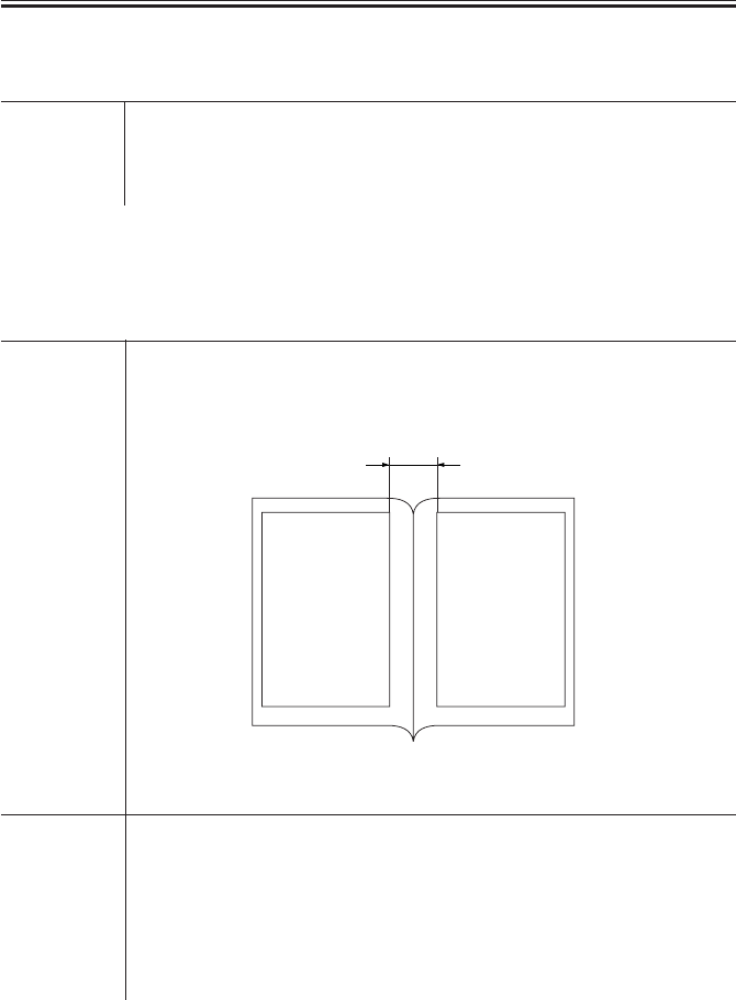
COPYRIGHT
©
2001 CANON INC. 2000 2000 2000 2000 CANON iR2200/iR2800/iR3300 REV.0 MAR. 2001
CHAPTER 5 SERVICE MODE
5-95 T
6.2 FEEDER
SIZE-SW Use it to enable or disable detection of mixed original sizes (AB and Inch
sizes).
Settings 0: disable (default), 1: enable
SORTER>OPTION
6.3 SORTER
BLNK-SW Use it to set the margin width (W) for both sides of a fold when a saddle
stitcher is used.
Settings 0: normal width (5 mm), 1: large width (10 mm; default)
F05-603-01
MD-SPRTN Use it to set the retraction movement in response to a finisher error (exclud-
ing a delivery motor error).
Caution After making a selection, be sure to turn off and then on the main power
switch.
Settings 0: disable retraction movement (default), 1: enable detraction move-
ment
W
FEEDER>OPTION

COPYRIGHT
©
2001 CANON INC. 2000 2000 2000 2000 CANON iR2200/iR2800/iR3300 REV.0 MAR. 2001
CHAPTER 5 SERVICE MODE
5-96 T
6.4 BOARD
MENUE-1 Use it to indicate level 1 of the printer settings menu.
Settings 0: do not indicate (default), 1: indicate
MENUE-2 Use it to indicate level 2 of the printer settings menu.
Settings 0: do not indicate (default), 1: indicate
MENUE-3 Use it to indicate level 3 of the printer settings menu.
Settings 0: do not indicate (default), 1: indicate
MENUE-4 Use it to indicate level 4 of the printer settings menu.
Settings 0: do not indicate (default), 1: indicate
PCI1-OFF Use it to enable or disable the function of slot 1 as when the board in slot 1
of PCI is out of order.
Settings 0: normal (default), 1: disable (not to use board function)
PCI2-OFF Use it to enable or disable the function of slot 2 as when the board in slot 2
of PCI is out of order.
Settings 0: normal (default), 1; disable (not to use board function)
PCI3-OFF Use it to enable or disable the function of slot 3 when the board in slot 3 of
PCI is out of order.
Settings 0: normal (default), 1: disable (not to use board function)
BOARD>OPTION
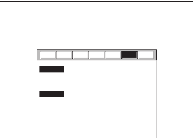
COPYRIGHT
©
2001 CANON INC. 2000 2000 2000 2000 CANON iR2200/iR2800/iR3300 REV.0 MAR. 2001
CHAPTER 5 SERVICE MODE
5-97 T
7 TEST Test Print Mode
The following screen will appear in response to COPIER>TEST; lists of items will fol-
low:
F05-701-01
Counter
Function
Adjust
I/O
Display
PG
NETWORK
Option
Test

COPYRIGHT
©
2001 CANON INC. 2000 2000 2000 2000 CANON iR2200/iR2800/iR3300 REV.0 MAR. 2001
CHAPTER 5 SERVICE MODE
5-98 T
PG
Use it to select the type of test print and generate it.
TYPE Enter the number or the type of test print you want, and press the OK key to
generate it.
Caution Be sure to return it to ‘00’ after printing the test print.
Settings 00: normal print, 01 through 08: as in T05-701-01
TXPH Use it to switch between print modes for test printing (PG>TYPE).
Settings 0: text mode, 1: photo mode
PG-PICK Use it to select the source of paper when generating a test print.
Settings 1: cassette 1 (default), 2: cassett 2, 3: cassette 3, 4: cassette 4, 5:
through 6: not used, 7: paper deck, 8: multifeeder tray
Type Input Numbers and Test Prints
T05-701-01
Input No. Description
00 image from CCD
(normal print)
01 grid
02 17 gradations
(w/ image correction)
03 17 gradations
(w/o image correction)
Input No. Description
04 blank
05 halftone
06 solid black
07 vertical straight lines
08 horizontal straight lines
--
COPIER>TEST>PG
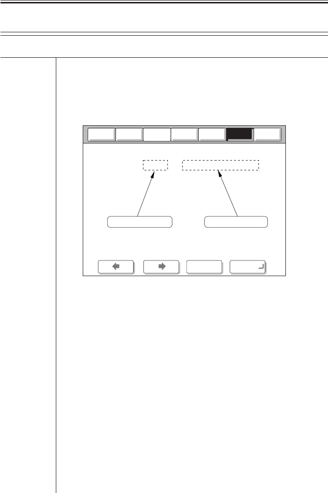
COPYRIGHT
©
2001 CANON INC. 2000 2000 2000 2000 CANON iR2200/iR2800/iR3300 REV.0 MAR. 2001
CHAPTER 5 SERVICE MODE
5-99 T
NETWORK
Use it to check the network-related items for connection.
PING Use it to check the connection between machine and the network (TCP/IP
only).
Caution Use this mode when checking the connection to the network at time of in-
stallation or when the connection to the network is faulty.
F05-701-02
Using the Mode
1) Turn off the main power switch.
2) Connect the network cable to the machine, and turn on the main power
switch.
3) Inform the user’s system administrator that the machine has been in-
stalled, and ask him/her to set up the network.
4) Inform the system administrator that the network connection will be
checked, and obtain the remote host address (IP address of the PC on the
user’s network) for sending a PING.
5) Make the following selections: COPIER>TEST>NETWORK>PING.
Then, enter the IP address obtained in step 4) using the keypad; and press
the OK key.
• If the connection to the network is correct, ‘OK’ will be indicated. (End
the work.)
• If ‘NG’ is indicated, check the connection for the network cable; if nor-
mal, go to step 6). If a fault is found, connect the cable correctly, and go to
step 5).
Counter
Option
Function
I/O
NETWORK 1/ 1 READY
< > < > < >
+/- OK
Display
Adjust
Result(OK/NG)
PING
IP address input
0 . 0 . 0 . 0
Test
COPIER>TEST>NETWORK

COPYRIGHT
©
2001 CANON INC. 2000 2000 2000 2000 CANON iR2200/iR2800/iR3300 REV.0 MAR. 2001
CHAPTER 5 SERVICE MODE
5-100 T
6) Make the following selections : COPIER>TEST>NETWORK>PING.
Then, enter the loop-back address* (127.0.0.1), and press the OK key and
then the Start key.
• If ‘NG’ is indicated, suspect a fault in the TCP/IP settings of the ma-
chine. Go back to step 3), and check the settings once again.
• If ‘OK’ is indicated, the TCP/IP setting may be assumed to be free of a
problem. However, the connection of the network interface board (NIC) or
the board itself may have a fault. Go to step 7).
*The loop-back address is returned in front of the NIC and, therefore, it en-
ables a check on the TCP/IP settings of the machine.
7) Make the following selections in service mode:
COPIER>TEST>NETWORK>PING. Then, press the OK key.
• If ‘NG’ is indicated, suspect a fault in the connection of the NIC or in
the NIC itself. Check the connection of the NIC or replace it.
• If ‘OK is indicated, the network setting of the machine and the NIC may
be assumed to be free of a fault.
In this case, the user’s network may have a problem. Report to the system
administrator for corrective action.
COPIER>TEST>NETWORK
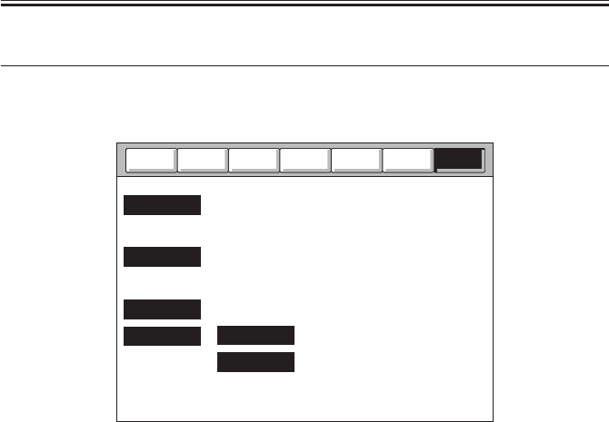
COPYRIGHT
©
2001 CANON INC. 2000 2000 2000 2000 CANON iR2200/iR2800/iR3300 REV.0 MAR. 2001
CHAPTER 5 SERVICE MODE
5-101 T
8 COUNTER Counter Mode
The following screen will appear in response to COPIER>COUNTER; lists of items will
follow:
F05-801-01
Clearing the Counter Readings
1) Select the item to clear (highlight).
2) Press the Clear key of the control panel.
• The counter will be cleared, and it will read ‘00000000’.
Dividing Papers Between Small-Size and Large-Size
Large-size (L): lager than A4/LTR
Small-size (S): A4/LTR or smaller
Test
Option
I/O
Display
PICK-UP
TOTAL
DRBL-1
DRBL-2
JAM
FEEDER
Adjust
Function
Counter

COPYRIGHT
©
2001 CANON INC. 2000 2000 2000 2000 CANON iR2200/iR2800/iR3300 REV.0 MAR. 2001
CHAPTER 5 SERVICE MODE
5-102 T
Guide to the Counters for Periodically Replaced Parts and Durables
The machine is equipped with counters for periodically replaced parts and durables
(DRBL-1/DRBL-2) so as to provide an idea of when to replace the parts.
A small-size sheet increments the counter reading by ‘1’, while a large-size sheet incre-
ments the count by ‘2’.
EX.
TR-ROOL / 00000201 / 00240000 / 0% !! 000082
[1] [2] [3] [4] [5] [6]
[1] indicates the name of the part; in the case of the example, the transfer charging roller.
[2] indicates the counter reading (actual number of sheets; be sure to clear the reading after
replacing the part).
[3] indicates the limit (number of sheets before replacement); to change, select the item, and
enter a number using the keypad, and then press the OK key.
[4] indicates the relationship between the counter reading and the limit.
[5] indicates a single exclamation mark (!) for a ratio between 90% and 100%, two marks
for 100% and higher; in the case of the example, no indication is made.
[6] indicates the number of days to the estimated time of replacement; the example shows
82 days.
List of COUNTER Items
Level 1: COUNETR Mode description
Level 2: TOTAL
Level 3: SERVICE1 total counter 1 for service
SERVICE2 total counter 2 for service
COPY copy counter
PDL-PRT PDL print counter
FAX-PRT fax received file print counter
RMT-PRT remote copy/print counter
BOX-PRT Box print counter
RPT-PRT repro print counter
2-SIDE double-sided print counter
SCAN scan counter
COPIER>COUNTER>TOTAL

COPYRIGHT
©
2001 CANON INC. 2000 2000 2000 2000 CANON iR2200/iR2800/iR3300 REV.0 MAR. 2001
CHAPTER 5 SERVICE MODE
5-103 T
Level 2: PICK-UP
Level 3: C1 cassette 1 pickup counter
C2 cassette 2 pickup counter
C3 cassette 3 pickup counter
C4 cassette 4 pickup counter
MF multifeeder tray pickup counter
DK paper deck pickup counter
2-SIDE double-sided 2nd side pickup counter
COPIER>COUNTER>FEEDER
Level 2: FEEDER
Level 3: FEED feeder(ADF) pickup total counter
COPIER>COUNTER>JAM
Level 2: JAM
Level 3: TOTAL machine total jam counter
FEEDER feeder (ADF) jam counter
SORTER sorter (finisher) jam counter
2-SIDE duplex unit jam counter
MF multifeeder tray jam counter
C1 cassette 1 jam counter
C2 cassette 2 jam counter
C3 cassette 3 jam counter
C4 cassette 4 jam counter
DK paper deck jam counter
COPIER>COUNTER>PICK-UP

COPYRIGHT
©
2001 CANON INC. 2000 2000 2000 2000 CANON iR2200/iR2800/iR3300 REV.0 MAR. 2001
CHAPTER 5 SERVICE MODE
5-104 T
Level 2: DRBL-1
Level 3: PRE-LMP pre-exposure lamp counter
TR-ROLL transfer charging roller counter
SP-SC-EL separation static eliminator paper passage counter
DVG-CYL developing cylinder counter
C1-PU-RL cassette 1 pickup roller counter
C1-SP-RL cassette 1 separation roller counter
C1-FD-RL cassette 1 feeding roller counter
C2-PU-RL cassette 2 pickup roller counter
C2-SP-RL cassette 2 separation roller counter
C2-FD-RL cassette 2 feeding roller counter
C3-PU-RL cassette 3 pickup roller counter
C3-SP-RL cassette 3 separation roller counter
C3-FD-RL cassette 3 feeding roller counter
C4-PU-RL cassette 4 pickup roller counter
C4-SP-RL cassette 4 separation roller counter
C4-FD-RL cassette 4 feeding roller counter
M-PU-RL multifeeder pickup counter
M-SP-PD multifeeder separation pad counter
FX-LW-RL fixing lower roller counter
FX-UNIT fixing unit count
FX-FILM fixing film counter
FX-CL-RL fixing cleaning roller counter
COPIER>COUNTER>DRBL-2
Level 2: DRBL-2
Level 3: DF-PU-RL ADF pickup roller counter
DF-SP-RL ADF separation plate counter
DF-SP-RD ADF separation pad counter
DF-FD-RL ADF feeding roller counter
LNT-TAPE ADF dust collecting tape counter
PD-PU-PL paper deck pickup roller counter
PD-SP-RL paper deck separation roller counter
PD-FD-RL paper deck feeding roller counter
FIN-STPR stapler counter
SDL-STPL saddle stapler counter
PUNCH punch counter
COPIER>COUNTER>DRBL-1

COPYRIGHT
©
2001 CANON INC. 2000 2000 2000 2000 CANON iR2200/iR2800/iR3300 REV.0 MAR. 2001
CHAPTER 6
SELF DIAGNOSIS

COPYRIGHT
©
2001 CANON INC. 2000 2000 2000 2000 CANON iR2200/iR2800/iR3300 REV.0 MAR. 2001
CHAPTER 6 SELF DIAGNOSIS
6-1 T
1 Self Diagnosis
The machine is equipped with a mechanism that checks the condition of the machine (es-
pecially sensor outputs) and indicates an error code in the control panel upon detection of a
fault.
The following tables show the codes used, timing of detection, and possible causes; a 4-
digit code is a detail code, and may be checked in service mode (COPIER>DISPLAY>JAM/
ERR).

COPYRIGHT
©
2001 CANON INC. 2000 2000 2000 2000 CANON iR2200/iR2800/iR3300 REV.0 MAR. 2001
CHAPTER 6 SELF DIAGNOSIS
6-2 T
Code Description
E716 Communication error (with pedestal)
E717 Communication error (with ASSIST)
E719 Card reader, coin vendor
communication error
E732 Reader communication error
E733 Printer communication error
E737 SDRAM error
E740 Ethernet board error
E741 PCI bus error
E742 RIP1 board error
E743 Mcon-Rcon communication error
(Rcon detection)
E803 MPWS power supply voltage error
(low voltage error)
E805 Fan rotation error
E901 Pedestal main motor rotation error
[ADF]
E420 Back-up data read error
E421 Back-up data write error
E422 IPC error
[Saddle Finisher-G1]
E501 Communication error (Punch unit)
E505 Back-up RAM
E510 Feed motor
E514 Delivery motor
E530 Width plate shift motor
E531 Stapler motor
E532 Stapler slide motor
E537 Alignment motor
E540 Tray ascent/descent motor
E577 Paddle motor
E590 Puncher motor
E592 Puncher sensor error
E593 Puncher shift motor
E5F1 Saddle folder motor
[Finisher-J1]
E500 Communication error
E514 Stack handling motor
E530 Rear alignment motor
E531 Stapler motor
E537 Front alignment motor
E577 Delivery motor
E580 Delivery tray ascent/descent motor
E585 Stack handling error
Code Description
[Copier]
E000 Heater temperature fault
(fails to increase)
E001 Overheating detection error
E002 Heater temperature error (fails to reach
specific level; inadequate increase)
E003 Heater temperature error (abnormal
drop; low-temperature detection)
E007 Fixing film rotation error
E010 Main motor rotation error
E014 Fixing motor rotation error
E019 Waste toner case full, sensor error
E032 DA unit communication error
E051 Horizontal registration HP
detention error
E064 Power supply voltage error
(high-voltage error)
E100 Laser BD error
E110 Polygon motor rotation error
E202 No. 1 mirror base HP detecting error
E204 ADF image leading edge signal
detection fault (absent)
E220 Lamp ON error
E225 Standard white plate/edge white
plate read error
E240 Mcon-Dcon communication error
E243 Mcon-control panel
communication error
E248 Backup (EEPROM) error
E261 Zero-cross signal error
E302 Shading error
E315 Image data processing error
E601 Image transfer error
E602 Hard disk error
E604 Image memory fault
E605 Image memory battery fault
E606 HDD error
E674 Fax board error
E677 PDL board mounting error
E710 IPC initialization error (Rcon)
E711 IPC register error (ctrl)
E712 Communication error (with ADF)
E713 Communication error (with sorter
finisher)

COPYRIGHT
©
2001 CANON INC. 2000 2000 2000 2000 CANON iR2200/iR2800/iR3300 REV.0 MAR. 2001
CHAPTER 6 SELF DIAGNOSIS
6-3 T
1.1 Detail Codes (copier)
E000
0000 The reading of the main thermistor does not reach 30°C 1 sec after the main
power switch is turned on. Or, it does not reach 70°C 2 sec thereafter.
Main cause The fixing film unit is faulty. The main thermistor has an open circuit. The
fixing heater has an open circuit. The main power supply PCB is faulty. The
DC controller PCB is faulty.
Caution To reset the error, execute the following in service mode:
COPIER>FUNCTION>CLEAR>ERR.
Action
1. Connector
Is the connector of the fixing assembly connected?
a. main power supply PCB (J8) <-> relay connector <-> heater
b. DC controller PCB (J320) <-> relay connector <-> thermistor
NO: Connect the connector.
2. Fixing film unit (thermistor)
Check the interval between pin 1 and pin 2 and between pin 3 and pin 4 of
the connectosr (4-pin) of the thermistor for electrical continuity. Is it ∞Ω
(open)?
YES: The heater has an open circuit, or the thermal switch is open. Re-
place the fixing film unit.
4. Main power supply PCB, DC controller PCB
Press the Start key. Is the drive voltage of the heater supplied by the con-
nector J8 of the main power supply PCB?
Main heater: between J8-1 (FSR1) and J8-5 (FSR COM)
Sub heater: between J8-3 (FSR2) and J8-5 (FSR COM)
YES: The heater drive power supply is faulty. Replace the main power
supply PCB.
NO: The thermistor control mechanism is faulty. Replace the DC con-
troller PCB.

COPYRIGHT
©
2001 CANON INC. 2000 2000 2000 2000 CANON iR2200/iR2800/iR3300 REV.0 MAR. 2001
CHAPTER 6 SELF DIAGNOSIS
6-4 T
E001
0000 The main thermistor detects 250°C or higher.
0001 The main thermistor or the sub thermistor detects overheating (hardware
circuit detection).
0002 The sub thermistor detects about 295°C or higher.
Main cause The fixing film unit is faulty (i.e., the thermistor has a short circuit). The
main power supply PCB is faulty. The DC controller PCB is faulty.
Caution To clear the error, execute the following in service move:
COPIER>FUNCTION>CLEAR>ERR.
Action
1. Fixing film unit
Check the interval between pin 1 and pin 2 and between pin 3 and pin 4 of
the connectors (4-pin) of the thermistor for electrical continuity. Is it 0 Ω
(short circuit)?
YES: The thermistor has a short circuit. Replace the fixing film unit.
REF.
If the thermistor has a short circuit, the indication in service mode
(COPIER>DISPLAY>ANALOG) will be as follows from the start: FIX-
C=250°C for the main thermistor; FIX-E=310°C for the sub thermistor.
2. Main power supply PCB, DC controller PCB
Try replacing the main power supply PCB. Is the problem corrected?
YES: End.
NO: Replace the DC controller PCB.

COPYRIGHT
©
2001 CANON INC. 2000 2000 2000 2000 CANON iR2200/iR2800/iR3300 REV.0 MAR. 2001
CHAPTER 6 SELF DIAGNOSIS
6-5 T
E002
0000 The temperature of the fixing film is as follows:
1. has exceeded 100°C, but does not reach 115°C within 1 sec thereafter.
2. has exceeded 140°C, but does not reach 150°C within 1 sec thereafter.
3. has exceeded 160°C, but does not reach 165°C within 1 sec thereafter.
Main cause The fixing film unit is faulty (i.e., the main thermistor TH1 has poor con-
tact, or the fixing heater is faulty). The main power supply PCB is faulty.
The DC controller PCB is faulty.
Caution To clear the error, execute the following in service mode:
COPIER>FUNCTION>FCLEAR>ERR.
Action See the description for E003.
E003
0000 The main thermistor reading is lower than 140°C when paper is moved.
Main cause The fixing film unit is faulty (i.e., the main thermistor (TH1) has poor con-
tact or has an open circuit; or, the fixing heater is faulty). The main power
supply PCB is faulty. The DC controller PCB is faulty.
Caution To clear the error, execute the following in service mode:
COPIER>FUNCTION>CLEAR>ERR.
Action
1. State
Turn on the power switch, and clear E002/E003. Thereafter, turn off and
then on the power switch. Does the fixing heater operate?
NO: See “The fixing heater fails to operate.”
2. Wiring
Is the wiring from the DC controller PCB to the fixing film unit normal?
NO: Correct the wiring.
3. Fixing film unit, DC controller PCB
Try replacing the fixing film unit. Is the problem corrected?
YES: End.
NO: Replace the DC controller PCB.

COPYRIGHT
©
2001 CANON INC. 2000 2000 2000 2000 CANON iR2200/iR2800/iR3300 REV.0 MAR. 2001
CHAPTER 6 SELF DIAGNOSIS
6-6 T
E007
0000 An error in the rotation of the fixing film is detected.
The reading of the main thermistor is 100°C or higher and, in addition, the
fixing film sensor does not detect the rotation of the film for 6 sec or more
while the fixing motor is driven.
Main cause The fixing film sensor (PS45) is faulty. The DC controller PCB is faulty.
Caution To clear the error, execute the following in service mode:
COPIER>FUNCTION>CLEAR>ERR.
Action
1. Wiring
Are the wring and the connectors connected securely?
DC controller PCB (J311) <-> relay connector <-> fixing film sensor
NO: Connect the wiring and the connectors.
2. Fixing film sensor
Check the fixing film rotation signal.When the fixing motor is rotating, is
the film rotation detection signal sent by the fixing film sensor to the
concoctor J311 of the DC controller PCB?
Film rotation detection signal: 5V pulse signal between J311-A9
(FILM_ROT_D) and J311-A8 (GND); at intervals of 100 msec ON and 440
msec OFF
NO: If the fixing film is normal, replace the sensor.
3. Fixing film unit, DC controller PCB
Is there a fault in the fixing film edge rotation detection mechanism?
YES: Replace the fixing film unit.
NO: Replace the DC controller PCB.

COPYRIGHT
©
2001 CANON INC. 2000 2000 2000 2000 CANON iR2200/iR2800/iR3300 REV.0 MAR. 2001
CHAPTER 6 SELF DIAGNOSIS
6-7 T
E010
0000 After the main motor drive signal is generated, the clock signal does to ar-
rive within 1.3 sec.
Main cause The main motor (M2) is faulty. the DC controller PCB is faulty.
Action
1. Connector
Is the connector of the main motor connected?
NO: Connect the connector.
2. Main power supply PCB
Is the drive voltage (24 V) of the main motor supplied by the main power
supply PCB?
Main power supply PCB: between J202-1 (24VU1-SW) and J202-2
(OVU1)
NO: Replace the main power supply PCB.
3. Main controller (M2), DC controller PCB
Press the Start key. Is the lock signal of the main motor present at the con-
nector J308 on the DC controller PCB?
Lock signal: J318-A10 (MM_LOCK)
YES: Replace the main motor.
NO: Check the wiring; if normal, replace the DC controller PCB.

COPYRIGHT
©
2001 CANON INC. 2000 2000 2000 2000 CANON iR2200/iR2800/iR3300 REV.0 MAR. 2001
CHAPTER 6 SELF DIAGNOSIS
6-8 T
E014
000 After the fixing motor drive signal is generated, the clock signal does not
arrive within 1.3 sec.
Main cause The fixing motor (M19) is faulty. The DC controller PCB is faulty.
Action
1. Connector
Is the connector of the fixing motor connected?
NO: Connect the connector.
2. Main power supply PCB
Is the drive voltage (24 V) of the fixing motor supplied by the main power
supply PCB?
Main power supply PCB: between J202-3 (24VU1-S) and J202-4 (OVU1)
NO: Replace the main power supply PCB.
3. Fixing motor (M19), DC controller PCB
Press the Start key. Is the lock signal of the fixing motor present at the con-
nector (J312) on the DC controller PCB?
Lock signal: J312-B4 (FSRM_LOCK*)
the DC controller PCB change from 0 to about 5 V?
YES: Replace the fixing motor.
NO: Replace the DC controller PCB.
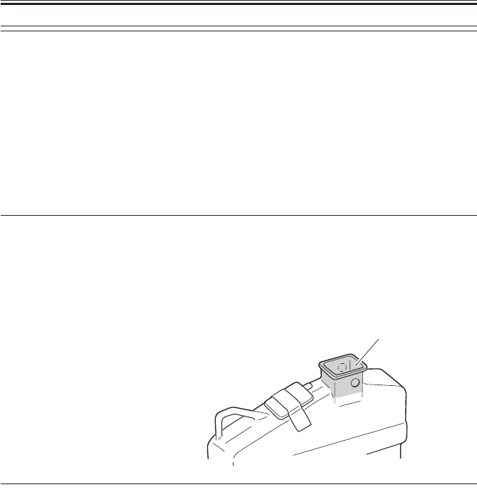
COPYRIGHT
©
2001 CANON INC. 2000 2000 2000 2000 CANON iR2200/iR2800/iR3300 REV.0 MAR. 2001
CHAPTER 6 SELF DIAGNOSIS
6-9 T
E019
0000 The waste toner case is full of waste toner.
Main cause The waste toner case is full. The waste toner case full detection mechanism
is soiled. The waste toner sensor is faulty. The DC controller PCB is faulty.
Caution To clear the error, dispose of the waste toner, and turn off and then on the
main power switch.
Action If the error is still indicated after disposing of the waste toner, perform the
following:
1. Waste toner case full detection mechanism
Remove the waste toner case, and turn off and then on the main power
switch. Is 'E019' absent?
YES: The waste toner case full detection assembly is soiled with toner.
Clean both inside and outside of area A of the waste toner case
with alcohol. Make sure that no dirt remains inside and outside the
area around the round recess.
2. Waste toner full sensor, DC Controller PCB
Try replacing the waste toner case full sensor. Is the problem corrected?
YES: End.
NO: Replace the DC controller PCB.
A

COPYRIGHT
©
2001 CANON INC. 2000 2000 2000 2000 CANON iR2200/iR2800/iR3300 REV.0 MAR. 2001
CHAPTER 6 SELF DIAGNOSIS
6-10 T
E032
0001 The DA unit connection is disconnected (after connection).
Main cause The DA unit is faulty. The main controller PCB is faulty.
Action
1. Connector
Is the DA unit connected securely?
NO: Connect it securely.
2. DA controller, Main controller PCB
Try replacing the DA unit. Is the problem corrected?
YES: End.
NO: Replace the main controller PCB.

COPYRIGHT
©
2001 CANON INC. 2000 2000 2000 2000 CANON iR2200/iR2800/iR3300 REV.0 MAR. 2001
CHAPTER 6 SELF DIAGNOSIS
6-11 T
E051
0000 At start-up, home position is not detected when the horizontal registration
assembly is moved 100 mm in the direction of home position.
Main cause The horizontal home position sensor is faulty. The horizontal registration
motor is faulty. The DC controller PCB is faulty.
Action
1. Connector
Are the connectors of the horizontal registration home position sensor and
the horizontal registration motor connected?
a. DC controller PCB (J304) <-> relay connector <-> horizontal registra-
tion home position sensor
b. DC controller PCB (J304) <-> relay connector <-> horizontal registra-
tion motor
NO: Connect the connectors.
2. Sensor lever (damage and interference), Sensor
Is abnormal noise heard from the horizontal registration assembly in keep-
ing with the motor rotation?
YES: a. The horizontal registration assembly is out of place because of
damage to the sensor lever. Replace the sensor lever.
b. The horizontal registration assembly malfunctions because of the
presence of foreign matter. Remove the foreign matter.
c. The sensor is faulty and cannot detect home position. Replace the
sensor.
3. Horizontal registration motor, DC controller PCB
Is the horizontal registration motor control signal generated by the DC con-
troller PCB?
J304-1/2: 24 V, J304-3/4/5/6: motor excitation signal
YES: The horizontal registration motor is faulty. Replace the motor.
NO: Replace the DC controller PCB.

COPYRIGHT
©
2001 CANON INC. 2000 2000 2000 2000 CANON iR2200/iR2800/iR3300 REV.0 MAR. 2001
CHAPTER 6 SELF DIAGNOSIS
6-12 T
E064
0000 The presence of a high-voltage error is communicated by the composite
power supply PCB. (The output for primary charging, developing, or trans-
fer has deviated from a specific level of voltage.)
Main cause The contact has poor connection. The wiring is faulty. The composite power
supply PCB is faulty. The DC controller PCB is faulty.
Action
1. Contact
Is any of the contacts of the primary charging roller, developing assembly,
or transfer charging roller soiled? Or, is there poor contact?
YES: Clean the contact, and set it once again.
2. Wiring
Is the wiring between the contacts for the following normal: DC controller
PCB (J301), composite power supply PCB (J136), primary charging roller,
developing assembly, transfer charging roller?
a. DC controller PCB (J301) <-> composite power supply PCB (J136)
b. composite power supply PCB (J130-7) <-> primary charging roller con-
tact
c. composite power supply PCB (J130-1) <-> developing assembly contact
d. composite power supply PCB (FT133) <-> transfer roller contact
NO: Correct the connection.
3. Composite power supply PCB, DC controller PCB
Try replacing the composite power supply PCB. Is the problem corrected?
YES: Yes.
NO: Replace the DC controller PCB.

COPYRIGHT
©
2001 CANON INC. 2000 2000 2000 2000 CANON iR2200/iR2800/iR3300 REV.0 MAR. 2001
CHAPTER 6 SELF DIAGNOSIS
6-13 T
E100
0001 The BD signal is not detected 10 times or more within 10 msec in 5 msec
after the generation of the laser drive signal.
0002 While the laser is ON, the BD signal cycle is outside a specific range 20
times or more continuously.
0003 While the laser is ON, the horizontal sync signal cycle is outside a specific
range 20 times or more.
Main cause The wiring is faulty (short circuit, open circuit). The BD PCB is faulty. The
laser scanner unit is faulty. The DC controller PCB is faulty.
Action
1. BD PCB
Try replacing the BD PCB. Is the problem corrected?
YES: End.
2. Laser scanner unit, DC controller PCB
Try replacing the laser scanner unit. Is the problem corrected?
YES: End.
NO: Replace the DC controller PCB.

COPYRIGHT
©
2001 CANON INC. 2000 2000 2000 2000 CANON iR2200/iR2800/iR3300 REV.0 MAR. 2001
CHAPTER 6 SELF DIAGNOSIS
6-14 T
E110
0000 The motor ready signal does not arrive within 15 sec after the laser scanner
motor drive signal is generated.
Main cause The wiring is faulty (short circuit, open circuit, disconnection). The laser
scanner motor (M10) is faulty. The main power supply PCB is faulty. The
DC controller PCB is faulty.
Action
1. Connector
Are the connector (J312) on the DC controller PCB and the relay connector
connected securely?
NO: Connect the connectors securely.
2. Main power supply PCB
During printing, does the voltage between J204-1 (+) and J204-2 (-) on the
main power supply PCB change from 0 to about 24 V?
NO: Replace the main power supply PCB.
3. Laser scanner unit, DC controller PCB
Try replacing the laser scanner unit. Is the problem corrected?
YES: End.
NO: Replace the DC controller PCB.

COPYRIGHT
©
2001 CANON INC. 2000 2000 2000 2000 CANON iR2200/iR2800/iR3300 REV.0 MAR. 2001
CHAPTER 6 SELF DIAGNOSIS
6-15 T
E202
The home position sensor does not go ON when the main power switch is turned on.
0001 The scanner home position sensor does not go OFF when the scanner is
moved forward by 40 mm.
0002 The scanner home position sensor does not go ON when the scanner is
moved reverse 450 mm.
Main cause The scanner home position sensor (PS400) is faulty. The scanner motor
(M400) is faulty. The reader controller PCB is faulty.
Action
1. State
Does the scanner operate when the power is turned on?
NO: See 4.2.9 “The No. 1 mirror base does not operate.”
2. Scanner home position sensor (PS400), Reader controller PCB
Move the No. 1 mirror base by hand from home position. Does the output
of the scanner home position sensor change? (J405-2 on the reader control-
ler PCB is 5 V (in HP) or 0V (away from HP))
NO: Replace the sensor.
YES: Replace the rear controller PCB.
E204
0001 While an original is being read, the image leading edge signal does not ar-
rive from the ADF.
Main cause The ADF controller PCB is faulty. The reader controller PCB is faulty.
Caution When this code occurs, no code is indicated, but the keys are locked. The
code may be checked in service mode: COPIER>DISPLAY>ERR.
Action
1. Read sensor (S2)
Try replacing the read sensor of the ADF. Is the problem corrected?
YES: End.
2. ADF controller PCB, Reader controller PCB
Try replacing the ADF controller PCB. Is the problem corrected?
YES: End.
NO: Replace the reader controller PCB.

COPYRIGHT
©
2001 CANON INC. 2000 2000 2000 2000 CANON iR2200/iR2800/iR3300 REV.0 MAR. 2001
CHAPTER 6 SELF DIAGNOSIS
6-16 T
E220
0001 A fault is detected on the inverter PCB for the scanning lamp.
Main cause The inverter PCB is faulty. The reader controller PCB is faulty.
Action
1. Wiring
Is the wiring from the scanning lamp to the reader controller PCB normal?
NO: Connect the connector firmly, and correct or replace the wiring.
2. Inverter PCB, Reader controller PCB
Try replacing the lamp inverter PCB. Is the problem corrected?
YES: End.
NO: Replace the reader controller PCB.
E225
0000 A specific level cannot be attained for the signal during CCD gain correc-
tion at power-on.
0002 The edge gain correction level is different from the correction level for the
preceding sheet by a specific level or more.
Main cause The scanning lamp is faulty. The CCD PCB is faulty. The rear controller
PCB is faulty.
Action
1. Scanning lamp (LAMP1)
Is the lamp ON during the initial operation after the main power switch is
turned on?
NO: Replace the scanning lamp.
2. CCD unit, Reader controller PCB
Try replacing the CCD unit. Is the problem corrected?
YES: End.
NO: Replace the reader controller PCB.

COPYRIGHT
©
2001 CANON INC. 2000 2000 2000 2000 CANON iR2200/iR2800/iR3300 REV.0 MAR. 2001
CHAPTER 6 SELF DIAGNOSIS
6-17 T
E240
0000 A fault occurs in communication between the CPU of the main controller
PCB and the CPU of the DC controller PCB.
Main cause The main controller PCB is faulty. The DC controller PCB is faulty.
Action
1. Wiring
Is the wiring from the min controller PCB to the DC controller PCB nor-
mal?
NO: Correct the wiring.
2. DC controller PCB, Main controlled PCB
Try replacing the DC controller PCB. Is the problem corrected?
YES: End.
NO: Replace the main controller PCB.
E243
0000 A fault occurs in the communication between the CPU of the control panel
PCB and the CPU of the main controller PCB.
Main cause The control panel CPU PCB is faulty. The main controller PCB is faulty.
Action
1. Wiring
Is the wiring from the main controller PCB to the DC controller PCB nor-
mal?
NO: Correct the wiring.
2. Control panel CPU PCB, Main controller PCB
Try replacing the control panel CPU PCB. Is the problem corrected?
YES: End.
NO: Replace the main controller PCB.

COPYRIGHT
©
2001 CANON INC. 2000 2000 2000 2000 CANON iR2200/iR2800/iR3300 REV.0 MAR. 2001
CHAPTER 6 SELF DIAGNOSIS
6-18 T
E248
0001 A difference is discovered between the ID in EEPROM read when the main
power switch is turned on and the ID in ROM upon comparison.
0002 The data read does not match the data written to EEPROM.
0003 A difference is discovered between the ID of EEPROM and the ID of ROM
upon comparison while writing data.
Main cause The EEPROM (IC403) of the reader controller PCB is faulty. The reader
controller PCB is faulty.
Action
1. Execute the following in service mode: COPIER>FUNCTION>CLEAR>CON. Is the
proem corrected?
YES: End. After executing the service mode, be sure to enter the service
mode data newly.
2. EE-PROM, Reader controller PCB
Try replacing the EE-PROM. Is the problem corrected?
YES: End. After replacement, be sure to enter the service mode data
newly.
NO: Replace the rear controller PCB. After replacement, be sure to en-
ter the service mode date newly.
E261
0000 The intervals of zero-cross signals deviate from the tolerance range while
the fixing heater is supplied with power.
Main cause The wiring is faulty (short circuit, open circuit). The main power supply
PCB is faulty. The DC controller PCB is faulty.
Making Corrections
1. Connectors
Are the connector J205 on the main power supply PCB and the connector
J308B on the DC controller PCB securely connected? (zero-cross signal:
J205-7 <-> J308B-1)
NO: Connect the connectors securely.
2. Main power supply PCB, Main controller PCB
Try replacing the main power supply PCB. Is the problem corrected?
YES: End.
NO: Replace the DC controller PCB.

COPYRIGHT
©
2001 CANON INC. 2000 2000 2000 2000 CANON iR2200/iR2800/iR3300 REV.0 MAR. 2001
CHAPTER 6 SELF DIAGNOSIS
6-19 T
E302
0001 During shading, the shading processing does not end on the reader control-
ler PCB after 1 sec.
0002 During stream reading, the edge white addition processing does not end on
the rear controller PCB after 10 sec.
Main cause The CCD PCB is faulty. The wiring is faulty (short circuit, open circuit).
The reader controller PCB is faulty.
Action
1. Connector
Are the connectors (J6001/J6002) on the CCD PCB and the connectors
(J5002/J5003) on the reader controller PCB connected securely?
NO: Connect the connectors securely.
2. CCD unit
Try replacing the CCD unit. Is the problem corrected?
YES: End.
3. Reader controller PCB, Main controller PCB
Try replacing the reader controller PCB. Is the problem corrected?
YES: End.
NO: Check the wiring; if normal, replace the main controller PCB.

COPYRIGHT
©
2001 CANON INC. 2000 2000 2000 2000 CANON iR2200/iR2800/iR3300 REV.0 MAR. 2001
CHAPTER 6 SELF DIAGNOSIS
6-20 T
E315
Any of the following is true in the image processing by the main controller:
1. The image data has a fault.
2. The encoding/decoding operation for image data has a fault.
3. The image processing element of the main controller PCB has a fault.
Main cause The image data is faulty. The main controller PCB is faulty. The HDD is
faulty.
Action
If this error occurs during normal copying or printing, the job in question
(image data) is cleared when the main power switch is turned off and then
on again; i.e., the machine will be reset.
If this error occurs frequently, however, a fault on the main controller PCB
is a possibility. Further, if this error occurs in a specific image within the
MAIL BOX, damage in data may be assumed; be sure to delete the image
from the MAIL BOX.

COPYRIGHT
©
2001 CANON INC. 2000 2000 2000 2000 CANON iR2200/iR2800/iR3300 REV.0 MAR. 2001
CHAPTER 6 SELF DIAGNOSIS
6-21 T
E601
0000 When an image is transferred between the main controller PCB and the
HDD, the main controller PCB detects a fault in control information.
0001 When an image is transferred between the main controller PCB and the DC
controller PCB, the DC controller PCB detects a fault in the control infor-
mation.
Main cause The wiring is faulty (short circuit, open circuit). The HDD is faulty. The DC
controller PCB is faulty. The main controller PCB is faulty
Action
a. E601-0000
1. Wiring
Are the connection and the cable between the connector J1017 on the main
controller PCB and the connector J1551 on the HDD normal?
YES: End.
NO: Correct the connection/cable.
2. HDD, Main controller PCB
Try replacing the HDD, and download the system software. Is the problem
corrected?
YES: End.
NO: Replace the main controller PCB.
b. E601-0001
1. Wiring
Are the connection and cable between the connector J122 on the DC con-
troller PCB and the connector J1015 on the main controller PCB normal?
NO: Correct the connection/cable.
2. DC controller PCB, Main controller PCB
Try replacing the DC controller PCB. Is the problem corrected?
YES: End.
NO: Replace the main controller PCB.

COPYRIGHT
©
2001 CANON INC. 2000 2000 2000 2000 CANON iR2200/iR2800/iR3300 REV.0 MAR. 2001
CHAPTER 6 SELF DIAGNOSIS
6-22 T
E602
0001 A mounting fault of the HDD is detected when the HDD is started up from
the BOOT ROM.
0002 A data read fault of the HDD is detected when the HDD is started up from
the BOOT ROM.
Main cause The wiring is faulty (short circuit, open circuit). The HDD is faulty. The
main controller PCB is faulty.
Action
1. Wiring
Are the connection and the cable between connector J1025 of the main con-
troller PCB and the connector J2005 of the HDD normal?
NO: Correct the connector/cable.
2. System software
Try re-installing the system software. Is the problem corrected?
YES: End.
3. HDD, Main controller PCB
Try replacing the HDD, and download the system software. Is the problem
corrected?
YES: End.
NO: Replace the main controller PCB.
E604
0000 A fault is detected in the image memory.
Main cause The wiring is faulty (short circuit, open circuit). The HDD is faulty. The
main controller PCB is faulty.
E605
0001 A fault is detected in the battery for the image memory.
Main cause The wiring is faulty (short circuit, open circuit). The HDD is faulty. The
main controller PCB is faulty.

COPYRIGHT
©
2001 CANON INC. 2000 2000 2000 2000 CANON iR2200/iR2800/iR3300 REV.0 MAR. 2001
CHAPTER 6 SELF DIAGNOSIS
6-23 T
E606
0001 A mounting fault of the HDD is detected when the HDD is started up from
the BOOT ROM.
Main cause The HDD is faulty. The main controller PCB is faulty.
Making Corrections
1. Wiring
Are the connection and cable normal between the connector J1025 on the
main controller PCB and the connector J2005 of the HDD?
NO: Correct the connection and the cable.
2. System software
Try re-installing the system software. Is the problem corrected?
YES: End.
3. HDD, Main controller PCB
Try replacing the HDD and downloading the system software. Is the prob-
lem corrected?
YES: End.
NO: Replace the main controller PCB.
E674
0000 A faulty occurs in the communication between the fax PCB and the main
controller PCB.
Main cause The wiring is faulty (short circuit, open circuit). The fax PCB is faulty. The
main controller PCB is faulty.
Making Corrections
1. Wiring
Are the connection and the cable between the connector J 1005 on the main
controller PCB and the connector J31 on the FAX PCB normal?
NO: Correct the connection and the cable.
2. FAX PCB, Main controller PCB
Try replacing the FAX PCB. Is the problem corrected?
YES: End.
NO: Replace the main controller PCB.

COPYRIGHT
©
2001 CANON INC. 2000 2000 2000 2000 CANON iR2200/iR2800/iR3300 REV.0 MAR. 2001
CHAPTER 6 SELF DIAGNOSIS
6-24 T
E677
0001 A fault occurs it the combination between any of the printer boards (acces-
sories) and the main controller PCB.
Main cause Any of the printer boards (accessories) is faulty. The main controller PCB is
faulty.
Action
1. Connector
Is the printer board (accessory) connected correctly?
NO: Correct the connection.
2. Printer board, Main controller PCB
Try replacing the printer board. Is the problem corrected?
YES: End.
NO: Replace the main controller PCB.

COPYRIGHT
©
2001 CANON INC. 2000 2000 2000 2000 CANON iR2200/iR2800/iR3300 REV.0 MAR. 2001
CHAPTER 6 SELF DIAGNOSIS
6-25 T
E710
0001 When the main power is turned on, the communication IC (IPC) on the
reader controller PCB cannot be initialized.
0002 When the main power is turned on, the communication IC (IPC) on the DC
controller PCB cannot be initialized.
0003 When the main power is trend on, the communication IC (IPC) on the main
controller PCB cannot be initialized.
Main cause The DC controller PCB is faulty. The reader controller PCB is faulty. The
machine controller PCB is faulty.
Action
Malfunction, PCBs
Turn off and then on the main power switch. Is the problem corrected?
YES: End.
NO: If E7100001, replace the reader controller PCB.
If E710-002, replace the DC controller PCB.
If E71-0003, replace the main controller PCB.

COPYRIGHT
©
2001 CANON INC. 2000 2000 2000 2000 CANON iR2200/iR2800/iR3300 REV.0 MAR. 2001
CHAPTER 6 SELF DIAGNOSIS
6-26 T
E711
0001 Data is written to the error register of the communication IC (IPC) on the
reader controller PCB four times or more within 1.5 sec.
0002 Data is written to the error register of the communication IC (IPC) on the
DC controller PCB four times or more within 2 sec.
0003 Data is written to the error register of the communication IC (IPC) on the
main controller PCB four times or more within 2 sec.
Main cause The connector has poor connection. The ADF controller PCB is faulty. The
finisher controller PCB is faulty. The DA unit PCB is faulty. The card
reader PCB is faulty.
Action
a. E711-0001
Connector, ADF controller PCB
Is the interface cable between the ADF controller PCB an the reader con-
troller PCB normal?
NO: Correct the cable.
YES: Replace the ADF controller PCB.
b. E711-0002
connector, Finisher controller PCB
Is the interface cable between the finisher controller PCB and the DC con-
troller PCB normal?
NO: Correct the cable.
YES: Replace the finisher controller PCB.
c. E711-0003
Connector, DA unit PCB
Is the interface cable between the DA unit PCB and the main controller
PCB normal?
NO: Correct the cable.
YES: Replace the NE controller PCB.

COPYRIGHT
©
2001 CANON INC. 2000 2000 2000 2000 CANON iR2200/iR2800/iR3300 REV.0 MAR. 2001
CHAPTER 6 SELF DIAGNOSIS
6-27 T
E712
0001 The communication is not resumed 3 sec or more after data has been writ-
ten to the error register of the communication IC (IPC) on the ADF control-
ler PCB.
0002 The transmission bit is not enabled 10 sec or more in the sync register of
the communication IC (IPC) on e reader controller PCB.
Main cause The connect has poor connection. The main power supply PCB is faulty.
The ADF controller PCB is faulty. The reader controller PCB is faulty.
Action
1. Connector
Is the interface able between the ADF controller PCB and the reader con-
troller PCB normal?
NO: Correct the cable.
2. Main power supply PCB
While the ADF is in operation, does the voltage between J203-2 (+) and
J203-1 (-) on the main power supply PCB change from 0 to about 24 V?
NO: Replace the main power supply PCB.
3. ADF controller PCB, Reader controller PCB
Try replacing the ADF controller PCB. Is the problem corrected?
YES: End.
NO: Replace the rear controller PCB.

COPYRIGHT
©
2001 CANON INC. 2000 2000 2000 2000 CANON iR2200/iR2800/iR3300 REV.0 MAR. 2001
CHAPTER 6 SELF DIAGNOSIS
6-28 T
E713
0000 The communication with the finisher is not resumed 3 sec or more after it is
disrupted.
Main cause The connector has poor connection. The option power supply PCB is faulty.
The finisher controller PCB is faulty. The DC controller PCB is faulty.
Action
1. Connector
Is the wiring between the finisher controller PCB and the options power
supply PCB and between the options power supply PCB and the DC con-
troller PCB normal?
NO: Correct the wiring.
2. Options power supply PCB
Is the voltage between HJ701-6 (+) and J701-7 (-) on the options power
supply PCB about 24 V?
NO: Replace the options power supply PCB.
3. Finisher controller PCB, DC controller PCB
Try replacing the finisher controller PCB. Is the problem corrected?
YES: End.
NO: Replace the DC controller PCB.

COPYRIGHT
©
2001 CANON INC. 2000 2000 2000 2000 CANON iR2200/iR2800/iR3300 REV.0 MAR. 2001
CHAPTER 6 SELF DIAGNOSIS
6-29 T
E716
0000 The ID signal is not detected within a specific period of time after the pres-
ence of a pedestal is detected.
Main cause The connector has poor connection. The main power supply PCB is faulty.
The pedestal controller PCB is faulty. The DC controller PCB is faulty.
Action
1. Connector
Is the wiring between the pedestal controller PCB and the main power sup-
ply PCB and between the main power supply PCB and the DC controller
PCB normal?
NO: Correct the wiring.
2. Main power supply PCB
Is the voltage between J206-2 (+) and J206-1 (-) on the main power supply
PCB about 24 V?
NO: Replace the main power supply PCB.
3. Pedestal controller PCB, DC controller PCB
Try replacing the pedestal controller PCB. Is the problem corrected?
YES: End.
NO: Replace the DC controller.
E717
0001 The communication with the DA unit is not resumed 3 sec or more after it
is disrupted.
Main cause The wiring is faulty (short circuit, open circuit). The DA unit PCB is faulty.
The main controller PCB is faulty.
Caution To clear the error, execute the following in service mode:
COPIER>FUNCTION>CLEAR>ERR.
Action
1. Connector
Is the connection between the DA unit PCB and the main controller PCB
secure?
NO: Correct the connection.
2. DA unit PCB, main controller PCB
Try replacing the DA unit PCB. Is the problem corrected?
YES: End.
NO: Replace the main controller PCB.

COPYRIGHT
©
2001 CANON INC. 2000 2000 2000 2000 CANON iR2200/iR2800/iR3300 REV.0 MAR. 2001
CHAPTER 6 SELF DIAGNOSIS
6-30 T
E719
0001 The communication between the Card Reader-C1 or the coin vendor and
the main controller PCB is disrupted.
Main cause The wiring is faulty (short circuit, open circuit). The Card Reader-C1 is
faulty. The coin vendor is faulty. The main controller PCB is faulty.
Caution To clear the error, execute the following in service mode:
COPIER>FUNCTION>CLEAR>ERR.
Action
1. Connector
Is the Cad Reader-C1 or the coin vendor connected securely?
NO: Connect it securely.
2. Coin vendor, Main controller PCB
Try replacing the Card Reader-C1 or the coin vendor. Is the problem cor-
rected?
YES: End.
NO: Replace the main controller PCB.
E732
0001 A fault is detected by the main controller PCB in the communication be-
tween reader controller PCB and the main controller PCB.
Main cause The connector has poor connection. The reader controller PCB is faulty.
Action
1. Connector, Reader controller PCB
Is the connection between the connector J1014 on the main controller PCB
and the connector J409 on the reader controller PCB normal?
NO: Correct the connection.
YES: Replace the reader controller PCB.

COPYRIGHT
©
2001 CANON INC. 2000 2000 2000 2000 CANON iR2200/iR2800/iR3300 REV.0 MAR. 2001
CHAPTER 6 SELF DIAGNOSIS
6-31 T
E733
0001 A fault is detected by the main controller PCB in the communication be-
tween the DC controller PCB and the main controller PCB.
Main cause The connector has poor connection. The DC controller PCB is faulty.
Action
1. Connector, DC controller PCB
Is the connection between the connector J1015 on the main controller PCB
and the conductor J316 on the DC controlled PCB normal?
NO: Correct the connection.
YES: Replace the DC controller PCB.
E737
0000 During self diagnosis at power-on, the DRAM check finds a fault in the
main controller PCB.
Main cause The connection of the IC socket is faulty. The main controller PCB is faulty.
Action
1. Connection
Is the DRAM fitted to the socket securely?
NO: Fit the DRAM securely.
2. DRAM, Main controller PCB
Try replacing the DRAM. Is the problem corrected?
YES: End.
NO: Replace the main controller PCB.

COPYRIGHT
©
2001 CANON INC. 2000 2000 2000 2000 CANON iR2200/iR2800/iR3300 REV.0 MAR. 2001
CHAPTER 6 SELF DIAGNOSIS
6-32 T
E740
0001 At power-on, the LAN card has a fault.
0002 The MAC address has a fault.
0003 The LAN card cannot be read.
Main cause The LAN card is faulty. The main controller PCB is faulty.
Action
1. Connector
Is the connection between the LAN card and the main controller PCB nor-
mal?
NO: Correct the connection.
2. LAN card, Main controller PCB
Try replacing the LAN card. Is the problem corrected?
YES: End.
NO: Replace the main controller PCB.
E741
0000 The PCI bus has a fault.
Main cause The PCI bus has poor connection. The main controller PCB is faulty.
Action Each PCI slot may be disabled in service mode to prevent the error:
BOARD>PCI1-OFF through PCI3-OFF.
1. Board
Is the connection between the relay board and the main controller PCB nor-
mal?
NO: Correct the connection.
2. Relay board, Main Controller PCB
Try replacing the relay board. Is the problem corrected?
YES: End.
NO: Replace the main controller PCB.

COPYRIGHT
©
2001 CANON INC. 2000 2000 2000 2000 CANON iR2200/iR2800/iR3300 REV.0 MAR. 2001
CHAPTER 6 SELF DIAGNOSIS
6-33 T
E743
0000 The reader controller PCB detects a fault in the communication between the
main controller PCB and the reader controller PCB.
Main cause The connector has poor connection. The main controller PCB has a fault.
Action
1. Connector, Main controller PCB
Is the connection between the connector J1014 on the main controller PCB
and the connector J409 on the reader controller PCB normal?
NO: Correct the connection.
YES: Replace the main controller PCB.
E744
0000 The BootROM on the main controller PCB and the system software are for
different models or are of different types.
Main cause The BootROM is not mounted correctly, or a fault occurred during down-
loading or when downloading the system software.
Making Corrections
Downloading (system software)
Check the types of the BootROM and the system software, and download
system software of the correct type.

COPYRIGHT
©
2001 CANON INC. 2000 2000 2000 2000 CANON iR2200/iR2800/iR3300 REV.0 MAR. 2001
CHAPTER 6 SELF DIAGNOSIS
6-34 T
E803
0000 The 24V output from the composite main power supply PCB is absent for 1
sec or more.
Main cause The wiring is faulty (short circuit, open circuit). The composite power sup-
ply PCB is faulty. The DC controller PCB is faulty.
Making Corrections
1. Connectors
Are the connectors J204 on the main power supply PCB and the connector
J300 on the DC controller PCB connected securely?
NO: Connect the connectors securely.
2. Main power supply PCB
Is 24 V supplied by the main power supply PCB (J204) to the DC controller
PCB (J300)?
(J204-5 <-> J300-5: OVU3, J204-6 <-> J300-6: OVU3,
J204-7 <-> J300-7: 24VU3, J204-8 <-> J300-8: 24VU3)
NO: Replace the main power supply PCB.
YES: Replace the DC controller PCB.

COPYRIGHT
©
2001 CANON INC. 2000 2000 2000 2000 CANON iR2200/iR2800/iR3300 REV.0 MAR. 2001
CHAPTER 6 SELF DIAGNOSIS
6-35 T
E805
The clock signal is absent for 5 sec or more after the fan drive signal has
been generated. The detail codes of the fans in question are as follows:
0001 developing fan (FM1)
0002 fixing fan (FM2)
0003 curl reducing fan (FM4)
0004 curl reducing fan (FM5)
0005 electrical unit fan (FM3)
Main cause The fan wiring is faulty (short circuit, open circuit). The fan is faulty. The
DC controller PCB is faulty.
Action
1. Foreign matter
Is there foreign matter that prevents the rotation of the fan?
YES: Remove the foreign matter.
2. Wiring, Connector
Are the wiring and connector of the fan normal?
Developing fan (FM1): DC controller PCB (J302B)
Fixing fan (FM2): DC controller PCB (J308B)
Curl reducing fan (FM4): DC controller PCB (J311B)
Curl reducing fan (FM5): DC controller PCB (J311B)
Electrical unit fan (FM3): main controller PCB (J1028)
NO: Correct the wiring and the connection.
3. Fan, DC controller PCB
Try replacing the fan. Is the problem corrected?
YES: End.
NO: Replace the DC controller PCB.

COPYRIGHT
©
2001 CANON INC. 2000 2000 2000 2000 CANON iR2200/iR2800/iR3300 REV.0 MAR. 2001
CHAPTER 6 SELF DIAGNOSIS
6-36 T
E901
0000 The motor ready signal does not arrive within 1.3 sec after the pedestal
main motor drive signal is generated.
Main cause The connector has poor connector. The pedestal main motor is faulty. The
main power supply PCB is faulty. The pedestal controller PCB is faulty.
The DC controller PCB is faulty.
Action
1. Connector
Is the wiring between the pedestal controller PCB and the main power sup-
ply PCB and between the main power supply PCB and the DC controller
PCB normal?
NO: Correct the wiring.
2. Main power supply PCB
Is the voltage between J206-2 (+) and J206-1 (-) on the main power supply
PCB about 24 V?
NO: Replace the main power supply PCB.
3. Pedestal main motor
Try replacing the pedestal main motor. Is the problem corrected?
YES: End.
4. Pedestal controller PCB, DC controller PCB
Try replacing the pedestal controller PCB. Is the problem corrected?
YES: End.
NO: Replace the DC controller PCB.

COPYRIGHT
©
2001 CANON INC. 2000 2000 2000 2000 CANON iR2200/iR2800/iR3300 REV.0 MAR. 2001
CHAPTER 6 SELF DIAGNOSIS
6-37 T
1.2 ADF Error Codes
When the ADF’s self diagnostic mechanism has gone ON, it may be reset by turning off
and then on its host machine.
The host machine can still generate copies in book mode if the ADF cable is discontented
even while the ADF is out of order.
E420
0001 When the power switch of the host machine is turned on, the back-up data
from the EEPROM cannot be read or the data that has been read has a fault.
Main cause The EEPROM is faulty. The ADF controller PCB is faulty.
E421
0001 The back-up data cannot be written to the EEPROM, or the data that has
been written has a fault.
Main cause The EEPROM has a fault. The ADF controller PCB has a fault.
E422
0001 While the ADF is in standby, the communication with its host machine is
disrupted for 5 sec or more; or, while the ADF is in operation, the commu-
nication with its host machine is disrupted for 0.5 sec or more.
Main cause The IPC communication is faulty. The communication line has an open cir-
cuit. The ADF controller PCB is faulty.

COPYRIGHT
©
2001 CANON INC. 2000 2000 2000 2000 CANON iR2200/iR2800/iR3300 REV.0 MAR. 2001
CHAPTER 6 SELF DIAGNOSIS
6-38 T
1.3 Saddle Finisher-G1 Error Codes
When the finisher’s self diagnostic mechanism has gone ON, it may be reset by turning
off and then on its host machine.
The host machine can still generate copies if the finisher cable is disconnected and the de-
livery path is set to the delivery tray of the host machine.
1.3.1 Error Code of the Finisher Unit
E501
0001 The communication between the finisher controller PCB and the puncher
drive PCB is disrupted.
Main cause The finisher controller PCB is faulty. The puncher drive PCB is faulty.
E505
0001 When the main power is turned on, the checksum of the finisher controller
PCB has a fault.
0002 When the main power is turned on, the checksum of the puncher driverPCB
has a fault.
Main cause The EEPROM is faulty. The finisher controller PCB is faulty. The puncher
driver PCB is faulty.
E510
0001 The feeding roller does not leave home position when the feed motor is
driven for 2 sec.
0002 The feeding roller does not return to home position when the feed motor is
driven for 2 sec.
Main cause The feed motor (M1) is faulty. The setting roller home position sensor is
faulty. The finisher controller PCB is faulty.

COPYRIGHT
©
2001 CANON INC. 2000 2000 2000 2000 CANON iR2200/iR2800/iR3300 REV.0 MAR. 2001
CHAPTER 6 SELF DIAGNOSIS
6-39 T
E514
0001 The delivery belt does not leave home position when the stack delivery mo-
tor is driven for 3 sec.
0002 The delivery belt does not return to home position when the stack delivery
motor is driven for 3 sec.
Main cause The stack delivery motor (M3) is faulty. The delivery belt home position
motor (PI7) is faulty. The finisher controller PCB is faulty.
E530
0001 The aligning plate (rear) does not leave home position when the alignment
motor (rear) is driven for 3 sec.
0002 The aligning plate (rear) does not return to home position when the align-
ment motor (rear) is driven for 3 sec.
Main cause The alignment motor (rear; M5) is faulty. The aligning plate home position
sensor (rear; PI5) is faulty. The finisher controller PCB is faulty.
E531
0001 The stapler does no leave home position when the stapler/folder motor is
driven for 1.5 sec.
0002 The stapler does not return to home position when the stapler/folder motor
is driven for 1.5 sec.
0003 The clock signal is disrupted for 1 sec or more while the stapler/folder mo-
tor is driven.
Main cause The stapler home position sensor (PI19) is faulty. The stapler/folder motor
(M7) is faulty. The stapler/folder clock sensor (PI4) is faulty. The finisher
controller PCB is faulty.
E532
0001 The stapler unit does not leave home position when the stapler slide motor
is driven for 4.5 sec.
0002 The stapler unit does not return to home position when the stapler slide mo-
tor is driven for 4.5 sec.
Main cause The slide home position sensor PI180 is faulty. The stapler slide motor
(M8) is faulty. The finisher controller PCB is faulty.

COPYRIGHT
©
2001 CANON INC. 2000 2000 2000 2000 CANON iR2200/iR2800/iR3300 REV.0 MAR. 2001
CHAPTER 6 SELF DIAGNOSIS
6-40 T
E537
0001 The aligning plate (front) does not leave home position when the alignment
motor (front) is driven for 3 sec.
0002 The aligning plate (front) does not return to home potion when the align-
ment motor (front) is driven for 3 sec.
Main cause The alignment motor (front; M4) is faulty. The aligning plate home position
sensor (front; PI4) is faulty. The finisher controller PCB is faulty.
E540
0001 The paper surface sensor remains unchanged 10 sec after the tray ascent/
descent motor is driven.
0002 The tray upper sensor goes ON while the tray is moving up.
0003 The clock for the clock sensor is disrupted for 10 sec or more while the tray
ascent/descent motor is driven.
Main cause The paper surface sensor (PI9) is faulty. The tray ascent/descent motor
clock sensor (PI17) is faulty. The tray upper limit sensor (PI15) is faulty.
The tray ascent/descent motor (M6) is faulty. The finisher controller PCB is
faulty.
E577
0001 The paddle does not leave home position when the paddle motor is driven
for 2 sec or more.
0002 The paddle does not return to home position when the paddle motor is
driven for 2 sec or more.
0003 The stack ascent/descent guide does not leave home position when the
paddle motor is driven for 2 sec or more.
0004 The stack ascent/descent guide does not return to home position when the
paddle motor is driven for 2 sec or more.
Main cause The paddle home position sensor (PI2) is faulty. The stack ascent/descent
home point sensor Pixx0 is faulty. The paddle motor (M2) is faulty. The fin-
isher controller PCB is faulty.

COPYRIGHT
©
2001 CANON INC. 2000 2000 2000 2000 CANON iR2200/iR2800/iR3300 REV.0 MAR. 2001
CHAPTER 6 SELF DIAGNOSIS
6-41 T
E590
0001 The puncher does not return to home position when the puncher motor is
driven for 250 msec.
0002 The clock from the puncher motor clock sensor is disrupted for 60 msec or
more when the puncher motor is driven.
Main cause The puncher home position sensor (PI1P) is faulty. The puncher motor
(M1P) is faulty. The puncher motor clock sensor (PI3P) is faulty. The
puncher driver PCB is faulty.
E592
In the course of sensor output automatic adjustment, the light-receiving
voltage is 2.5 V or less even when the light-emitting voltage is set to 4.4 V.
In the course of output automatic adjustment, the light-receiving voltage is
2.5 V or more even when the light-emitting voltage is set to 0 V.
In the course of sensor output automatic adjustment, the light-emitting volt-
age is set to 4.4 V or more.
0001 to 0005 Horizontal registration sensor
0006 Puncher waste full sensor
Main cause The horizontal registration sensor is faulty. The puncher waste sensor is
faulty. The puncher driver PCB is faulty.
E593
0001 The puncher not leave home position when the puncher shift motor is
driven for 1 sec.
0002 The puncher does not return to home position when the puncher shift motor
is driven for 1 sec.
Main cause The horizontal registration home position sensor (PI2P) is faulty. The
puncher shift motor (M2P) is faulty. The puncher drive PCB is faulty.

COPYRIGHT
©
2001 CANON INC. 2000 2000 2000 2000 CANON iR2200/iR2800/iR3300 REV.0 MAR. 2001
CHAPTER 6 SELF DIAGNOSIS
6-42 T
E5F1
0001 The folding roller does not leave home position when the stapler/folder mo-
tor is driven for 1.5 sec.
0002 The folding roller does to return to home position when the stapler/folder
motor is driven for 3.5 sec or more.
0003 The clock is disrupted for 1 sec or more while the stapler/folder motor is
driven.
Main cause The folding roller home position sensor (PI12) is faulty. The stapler/folder
motor (M7) is faulty. The stapler/folder clock sensor (PI14) is faulty. The
finisher controller PCB is faulty.

COPYRIGHT
©
2001 CANON INC. 2000 2000 2000 2000 CANON iR2200/iR2800/iR3300 REV.0 MAR. 2001
CHAPTER 6 SELF DIAGNOSIS
6-43 T
1.4 Finisher-J1 Error Codes
When the finisher’s self diagnostic mechanism has gone ON, it may be reset by turning
off and then on its host machine.
While the finisher is out of order, prints can still be made by disabling the finisher opera-
tion as follows (other than delivery):
1) Service mode
[1] Turn off and then on the main power switch.
[2] Set '1' to SORTER>OPTION>MD-SPRTN.
[3] Turn off and then on the main power switch.
2) User mode
[1] Turn off and then on the main power switch.
[2] Set 'OFF' the following: 'adjustment/cleaning'>'staple/offset function'.
[3] Turn off and then on the main power switch.
E500
0000 The communication between the copier and the finisher is disrupted and is
not corrected for 5 sec or less.
Cause The copier harness is faulty. (disconnected connector, open circuit) The fin-
isher controller PCB or the copier’s DC controller PCB is faulty.
E514
0000 At the start of the motor CW operation, the stack handling motor (M2) may
be driven for a specific number of rotations; however, the stack delivery le-
ver home position sensor (S8) does not go ON.
Cause The stack handling motor (M2) is faulty. The stack delivery lever home po-
sition sensor (S8) is faulty, the connector is disconnected, or an open circuit
exits. The stack handling motor (M2) relay harness is faulty. The return
roller is faulty.
E530
0000 The alignment motor (M4) is driven for a specific number of rotations, but
the aligning plate home position sensor (S7) does not go ON.
The alignment motor (M4) is driven for a specific number of rotations, but
the aligning plate home position sensor (S7) does not go OFF.
Cause The rear alignment motor (M4) is faulty. The rear aligning plate home posi-
tion sensor (S7) is faulty. The rear alignment motor relay harness is faulty.
The rear aligning plate is subjected to an excess load.

COPYRIGHT
©
2001 CANON INC. 2000 2000 2000 2000 CANON iR2200/iR2800/iR3300 REV.0 MAR. 2001
CHAPTER 6 SELF DIAGNOSIS
6-44 T
E531
0000 The stapling home position sensor (S16) does not go off 0.5 sec after the
stapler motor is rotated CW.
The stapling home position sensor (S16) dos not go ON with 0.5 sec after
the stapler motor is rotated CW and, thereafter, the sensor does not go ON
within 0.5 sec after the motor is rotated in reverse.
Cause The stapler motor (M6) is faulty. The stapling home position sensor (S16)
is faulty. The stapler harness is faulty. The finisher controller PCB is faulty.
E537
0000 The aligning plate home position sensor (S6) does not go ON when the
front alignment motor (M3) is driven for a specific number of rotations.
The aligning plate home position sensor (S6) does not go OFF when the
front alignment motor (M3) is driven for a specific number of rotations.
Cause The front alignment motor (M3) is faulty. The front aligning plate home po-
sition sensor (S6) is faulty. The front alignment motor relay harness is
faulty. The front aligning plate is subjected to an excess load.
E577
0000 The return roller does not reach home position when the delivery motor
(Ml) has been driven as much as will move it to the return roller home posi-
tion sensor (S3).
Cause The delivery motor (M1) or the finisher controller PCB is faulty. The return
roller home position sensor (S3) is faulty, the harness connector is discon-
nected, or an open circuit exits. The delivery motor relay harness is faulty.
The return roller is faulty.

COPYRIGHT
©
2001 CANON INC. 2000 2000 2000 2000 CANON iR2200/iR2800/iR3300 REV.0 MAR. 2001
CHAPTER 6 SELF DIAGNOSIS
6-45 T
E580
0000 The delivery tray upper limit sensor (S13) goes ON while the delivery tray
ascent/descent motor (M5) is in operation.
The clock signal of the delivery tray ascent/descent motor clock sensor (S9)
is not detected 15 times or more within 0.8 sec while the delivery tray as-
cent/descent motor (M5) is in operation.
The delivery tray paper height sensor (S10) does not go ON 4 sec after the
delivery tray ascent/descent motor (M5) starts to move up.
The delivery tray paper height sensor (S10) does not go OFF 4 sec after the
delivery tray ascent/descent motor (M5) starts to move down.
Cause The delivery tray ascent/descent motor (M5) is faulty. The delivery tray pa-
per height sensor (S10) is faulty, the harness is disconnected, or an open
circuit exits. The delivery tray ascent/descent motor lock sensor (S9) is
faulty, the connector is disconnected, or an open circuit exits. The delivery
tray ascent/descent motor is subjected to an excess load. The finisher con-
troller PCB is faulty.
E585
0000 At the start of the motor CCW operation, the stack handling motor (M2)
may be driven for a specific number of rotations; however, the stack deliv-
ery lever home position sensor (S8) does not go ON.
Cause The stack handling motor (M2) is faulty. The stack delivery lever home po-
sition sensor (S8) is faulty, the connector is disconnected, or an open circuit
exits. The stack handling motor (M2) relay harness is faulty. The return
roller is faulty.

COPYRIGHT
©
2001 CANON INC. 2000 2000 2000 2000 CANON iR2200/iR2800/iR3300 REV.0 MAR. 2001
CHAPTER 7
UPGRADING

COPYRIGHT
©
2001 CANON INC. 2000 2000 2000 2000 CANON iR2200/iR2800/iR3300 REV.0 MAR. 2001
CHAPTER 7 UPGRADING
7-1 T
1 Upgrading
1.1 Outline
The machine is upgraded either by downloading data from a PC or by replacing its
DIMM/ROM.
The following five items are upgraded by downloading from a PC:
• BOOT ROM (machine J1009 DIMM ROM)
• HD Format (machine HDD; formatting)
• Language (machine HDD)
• RUI (machine HDD)
• System (machine HDD)
• DADF-H1 (CPU; Use the downloader PCB) See 1.6 Downloader PCB
• Finisher-J1 (CPU; Use the downloader PCB) See 1.6 Downloader PCB
As indicated, the language module may also be downloaded.
The machine may be connected to a network when downloading data from a PC.
For instructions on upgrading by means of replacing the DIMM/ROM, see 1.7 “Upgrad-
ing by Replacing the DIMM/ROM.”
1.1.1 Download Mode
The machine provides two types of download modes; although any of the two may be
used to download all files, select with care if you want to format the hard disk (select the
HD Format), as a specific partition must be selected.
You can use any of the two when using a parallel cable; however, the use of a network
cable will require you to start up the machine’s network environment, necessitating the use
of downloading in service mode.
• Downloading in Download Mode
To start download mode,
1) While holding down ‘2’ and ‘8’ on the keypad at the same time, turn on the power
switch.
2) Hold down ‘2’ and ‘8’ on the keypad until the bottom of the touch panel indicates the
message “Download Mode.”
Partition Available for Formatting the Hard Disk
/BOOTDEV
ALL
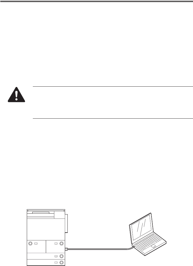
COPYRIGHT
©
2001 CANON INC. 2000 2000 2000 2000 CANON iR2200/iR2800/iR3300 REV.0 MAR. 2001
CHAPTER 7 UPGRADING
7-2 T
• Downloading in Service Mode
To start download mode,
1) Start service mode.
2) Make the following selection: COPIER>FUNCTION>SYSTEM>DOWNLOAD. Then,
press ‘OK’ so that the machine will be in download standby mode (message
“STANDBY”).
Partition Available for Formatting the Hard Disk
/PDLDEV
/FSTDEV
/DOSDEV
If you use the Service Support Tool while the machine is not in download
mode, the machine will treat data from the interface as a local print job and,
accordingly, will increment the job count.
When you use the Service Support Tool, be sure to switch the machine to
download mode in advance by following the instructions on the screen.
1.1.2 Making Pre-Checks
Prepare the following:
• PC to which the Service Support Tool (version 1.25 or later) has been installed
• System CD (for iR2200/iR2800/iR3300)
• Connection cable
The type of cable depends on how the machine is to be connected to the PC.
• In the case of a bi-Centronics interface,
obtain a parallel cable (indicating IEEE 1284Std-compliant).
• Using a Network Cable
Connect the machine with the PC using a cross Ethernet cable or a straight Ethernet
cable and a HUB.
The following shows how a cross Ethernet cable may be used.
F07-101-01
Cross Cable

COPYRIGHT
©
2001 CANON INC. 2000 2000 2000 2000 CANON iR2200/iR2800/iR3300 REV.0 MAR. 2001
CHAPTER 7 UPGRADING
7-3 T
If you are using a straight Ethernet cable and a HUB, you are encouraged to
connect the machine with the PC on a one-on-one basis, outside the user’s
network environment.
F07-101-02
Straight Cable Straight Cable

COPYRIGHT
©
2001 CANON INC. 2000 2000 2000 2000 CANON iR2200/iR2800/iR3300 REV.0 MAR. 2001
CHAPTER 7 UPGRADING
7-4 T
Memo
Differences in Connection Between Bi-Centronics Cable and Network
Cable
Each has its own advantages and disadvantages; select one to suit specific
needs:
Connection with a Bi-Centronics Cable (using a parallel cable)
Advantages:
• You can use the Service Support Tool without considering the environ-
ment of the user’s network.
• If the system is not installed on the hard disk, the system may be installed
or the hard disk may be formatted using download mode.
Disadvantages:
• The specifications of the PC used or the chip set may not allow the use of
high-speed mode, i.e., it has a low level of compatibility.
• The PC must have a parallel interface.
• You can not use high-speed mode on Windows NT or Windows 2000.
Connection with a Network Cable
Advantages:
• It is relatively high speed.
• It is less dependent on the PC to be used.
• The use of a cross cable enables direct connection.
Disadvantages:
• You must change the network settings of the machine or the PC to suit the
user’s network environment. More importantly, you must change the ma-
chine back to its initial settings after the task.
• You must have a good knowledge of networking.
• The system must start up normally and the network settings must be cor-
rect.
Memo
Points to Note When Using a Bi-Centronics Interface and a Network
The Service Support Tool allows you to select one of two interfaces to suit
specific needs. If both are in use, you must turn the machine off and then on
first before making a switch-over (i.e., from Bi-Centronics to Network or
vice versa), thereby preventing errors in the event of simultaneous writing
operations.
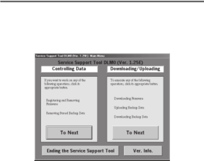
COPYRIGHT
©
2001 CANON INC. 2000 2000 2000 2000 CANON iR2200/iR2800/iR3300 REV.0 MAR. 2001
CHAPTER 7 UPGRADING
7-5 T
1.2 Data Control
You must install the files to use (System, RUI, HD Format , BOOT, Language) before ex-
ecuting downloading.
1) Start up the Service Support Tool.
2) Under ‘Controlling Data’, select ‘To Next’.
F07-102-01
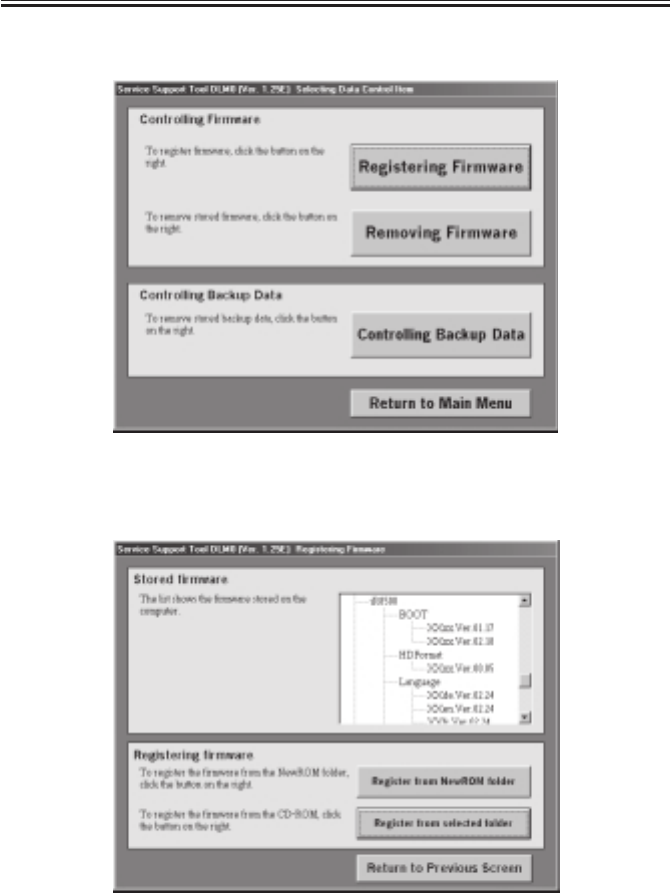
COPYRIGHT
©
2001 CANON INC. 2000 2000 2000 2000 CANON iR2200/iR2800/iR3300 REV.0 MAR. 2001
CHAPTER 7 UPGRADING
7-6 T
3) From the Control Work screen of the firmware, select ‘Registering Firmware’.
F07-102-02
4) From the following screen, select ‘Register from selected folder’.
F07-102-03
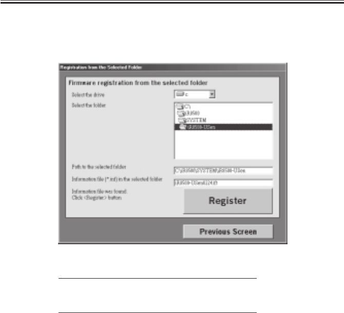
COPYRIGHT
©
2001 CANON INC. 2000 2000 2000 2000 CANON iR2200/iR2800/iR3300 REV.0 MAR. 2001
CHAPTER 7 UPGRADING
7-7 T
5) Select the drive to which you have inserted the System CD.
6) Select the folder of the suitable version, and click ‘Register’.
On this screen, it is in the case of iR8500.
F07-102-04
Note: For iR2800/iR3300 User
You must select the folder of iR2200.
Such software can be used in common.
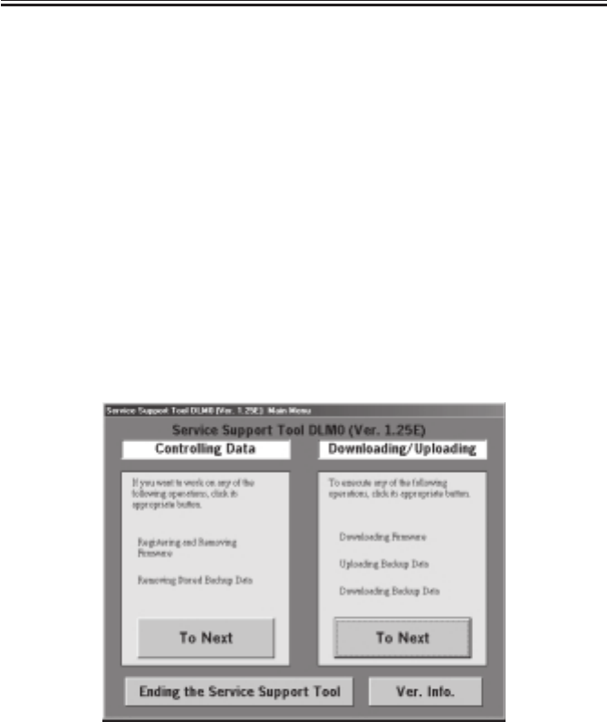
COPYRIGHT
©
2001 CANON INC. 2000 2000 2000 2000 CANON iR2200/iR2800/iR3300 REV.0 MAR. 2001
CHAPTER 7 UPGRADING
7-8 T
1.3
Downloading the System Software, RUI, and Language Module
1.3.1 Making Connections
The discussions that follow are based on the use of a parallel cable:
• Check to make sure that the Processing/Data lamp is OFF.
1) Turn off the machine’s main power switch, and disconnect the power plug and the
network cable.
2) Using a parallel cable, connect the PC to the parallel connector on the left side of the
controller.
• At this time, the PC must remain OFF.
• Connect the 25-pin connector of the cable to the PC and the 36-pin connector to the ma-
chine.
3) Turn on the power switch of the PC, and start up the Service Support Tool.
4) Connect the machine’s power plug to the power outlet, and turn on the main power
switch.
1.3.2 Downloading
1) Under ‘Downloading/Uploading’, select ‘To Next’.
F07-103-01
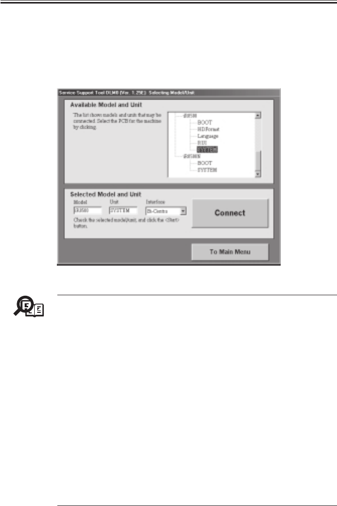
COPYRIGHT
©
2001 CANON INC. 2000 2000 2000 2000 CANON iR2200/iR2800/iR3300 REV.0 MAR. 2001
CHAPTER 7 UPGRADING
7-9 T
2) Start the machine’s service mode, and make the following selections:
COPIER>FUNCTION>SYSTEM>DOWNLOAD. Then, press ‘OK’ so that the machine
will be in download standby mode (notation “STNDBY”).
3) Select SYSTEM, RUI, or Language, and select the interface (either Bi-Centronics or
Network). The discussions that follow assume that you have selected bi-Centronics.
On this screen, it is in the case of iR8500.
F07-103-02
Memo
About the Language Module (Language)
A language module is a unit containing the language data needed to indi-
cate messages in the control panel, each module designed for a specific lan-
guage. Install only those language modules you need, thus saving time
spent for downloading. You can switch among installed language modules
in user mode: common settings> display language. At time of shipment,
five modules (languages) are installed. The modules will be lost once you
format the had disk, requiring you to install them once again to suit the
needs of the user. To check the version of the modules, make the following
selections: COPIER>DISPLAY>VERSION>LANG-XX. Check to make
sure that the version of each language module matches the version of the
installed system software; otherwise, use the langue module built into the
system software to start up. The built-in module is not part of the modules
that may be selected as the display language; for this reason, you will not
be able to make use of the language switch unless you have installed mod-
ules independently of the system software. If you replace an existing lan-
guage module with a module of an inappropriate version, ‘E744-0001’ will
be indicated when the machine is started up for the first time; to reset the
error, install a module of the correct version.

COPYRIGHT
©
2001 CANON INC. 2000 2000 2000 2000 CANON iR2200/iR2800/iR3300 REV.0 MAR. 2001
CHAPTER 7 UPGRADING
7-10 T
4) If the notation in the upper right of the screen is ‘High-Speed’, go to step 6); if ‘Low-
Speed’, go to step 5).
F07-103-03
5) Click ‘Switch operation mode’ to bring up the Centronics Communication Mode
Change screen. Select ‘High-Speed’, and press ‘OK’ to move to step 6).
Memo
High-speed mode is not supported on Windows NT and Windows 2000.
F07-103-04
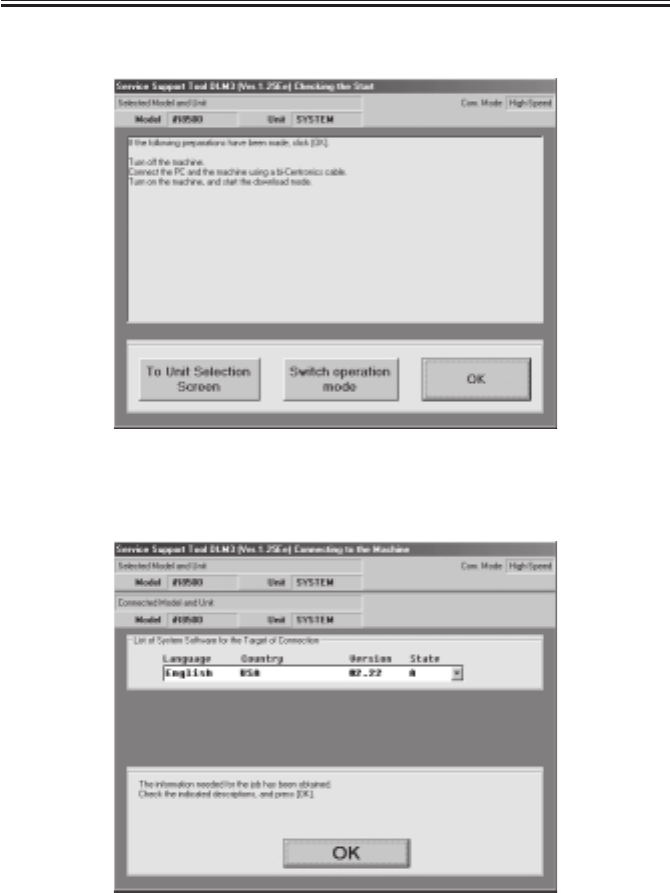
COPYRIGHT
©
2001 CANON INC. 2000 2000 2000 2000 CANON iR2200/iR2800/iR3300 REV.0 MAR. 2001
CHAPTER 7 UPGRADING
7-11 T
6) Click ‘OK’ to start connection.
F07-103-05
7) When connection is done, the following screen will appear. Click ‘OK’.
F07-103-06
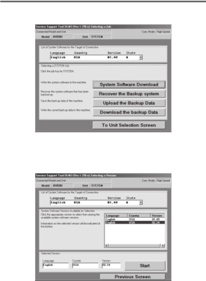
COPYRIGHT
©
2001 CANON INC. 2000 2000 2000 2000 CANON iR2200/iR2800/iR3300 REV.0 MAR. 2001
CHAPTER 7 UPGRADING
7-12 T
8) Select ‘System Software Download’ of the Service Support Tool screen.
F07-103-07
9) Select the files suited to the language and the country in question from the ‘list of soft-
ware’ on the Service Support Tool screen, and click ‘Start’.
F07-103-08
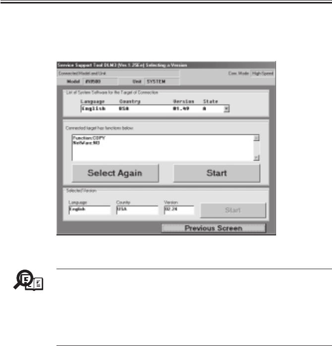
COPYRIGHT
©
2001 CANON INC. 2000 2000 2000 2000 CANON iR2200/iR2800/iR3300 REV.0 MAR. 2001
CHAPTER 7 UPGRADING
7-13 T
10) The following screen will appear to indicate the types of software that will be down-
loaded: “Function: COPY/PRINTER” “NetWare: YES/NO.” If the indications are cor-
rect, click ‘Start’.
F07-103-09
Memo
Installing System Software with Different Functions
Normally, you cannot upgrade existing system software by means of down-
loading unless the old and new systems have the same functions; an attempt
to do so will result in an error. If the user obtains the official Upgrading kit
and follow the appropriate procedure, however, such upgrading is possible;
for details, see the Installation Procedure that comes with the Upgrading
kit.
11) Check the progress bar, which indicates the progress of downloading.
12) When downloading ends, turn off the PC by making the following selections: OK>To
Unit Selection Screen>OK>To Main Menu>Ending the Service Support Tool>End.

COPYRIGHT
©
2001 CANON INC. 2000 2000 2000 2000 CANON iR2200/iR2800/iR3300 REV.0 MAR. 2001
CHAPTER 7 UPGRADING
7-14 T
1.3.3 After Downloading
1) Turn off the machine’s main power switch, and disconnect its power plug.
2) Turn off the PC.
3) Disconnect the parallel cable from the PC and the machine.
4) If a network cable is connected, connect it to its correct location, and turn on the
machine’s main power switch.
5) When the machine has started up, start service mode to check the system version for the
HDD: COPIER>DISPLAY>VERSION>MN-CONT.
1.4 Upgrading the BOOT ROM
1.4.1 Making Preparations
When you upgrade the machine’s BOOT ROM, you will directly replace the contents of
the ROM DIMM. Take full care.
1) Check to see that the machine’s Data lamp is OFF.
2) Turn off the machine’s main power switch, and disconnect the power plug and the net-
work cable.
Memo
Limits on Preparing the BOOT ROM
You will not be able to prepare the BOOT ROM unless the following condi-
tions are met:
On this screen, it is in the case of iR8500.
• The model of the machine is the same; e.g., you cannot use the iR2200
BOOT ROM data to upgrade an iR5000.
• The parameter “function” (COPY or PRINTER) must match when down-
loading the system software; i.e., you cannot use the iR2200N (PS/PCL
model) BOOT ROM data to upgrade an iR2200. (The same is true of
from PS/PCL model to COPY.)
Any attempt made in disregard of the above will cause a mismatch error
when the machine runs a check before writing.
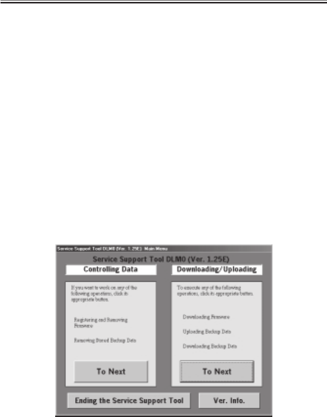
COPYRIGHT
©
2001 CANON INC. 2000 2000 2000 2000 CANON iR2200/iR2800/iR3300 REV.0 MAR. 2001
CHAPTER 7 UPGRADING
7-15 T
1.4.2 Connection
The following discussions assume the use of a network cable (cross cable).
Making Preparations
If you want to download firmware to the machine using a network, you need to set up the
PC and the machine’s network environment.
Use TCP/IP as the communication protocol for downloading form a network using the
Service Support Tool. Connect the PC to the machine by way of the network, and check to
make sure that all are ready for communication by sending a PING command from the PC
or the machine.
1) Connect the machine’s network connector (RJ-45) and the network connector of the PC
using a network cable (cross cable).
2) Turn on the PC, and start up the Service Support Tool.
3) Connect the machine’s power plug to the power outlet, and start service mode; make the
following selections: COPIER>FUNCTION>SYSTEM>DOWNLOAD. Then, click
‘OK’ so that the machine will be in download standby mode (notation “STNDBY”).
1.4.3 Preparing BOOT ROM
The discussions that follow assume upgrading an iR8500 (COPY model).
1) User ‘Downloading/Uploading’, select ‘To Next’.
F07-104-01
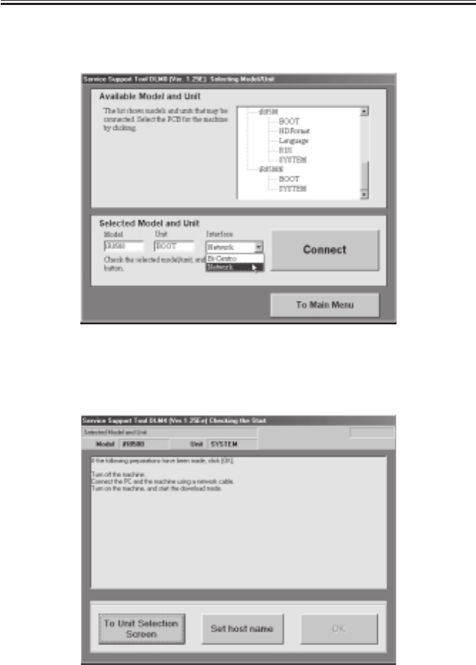
COPYRIGHT
©
2001 CANON INC. 2000 2000 2000 2000 CANON iR2200/iR2800/iR3300 REV.0 MAR. 2001
CHAPTER 7 UPGRADING
7-16 T
2) Select the correct BOOT, and select an interface (bi-Centronics or Network). (The ex-
ample selects iR8500 for BOOT, and Network is selected for Interface.)
F07-104-02
3) To enter the IP address or the host name of the machine to connect, click ‘Set host
name’.
F07-104-03
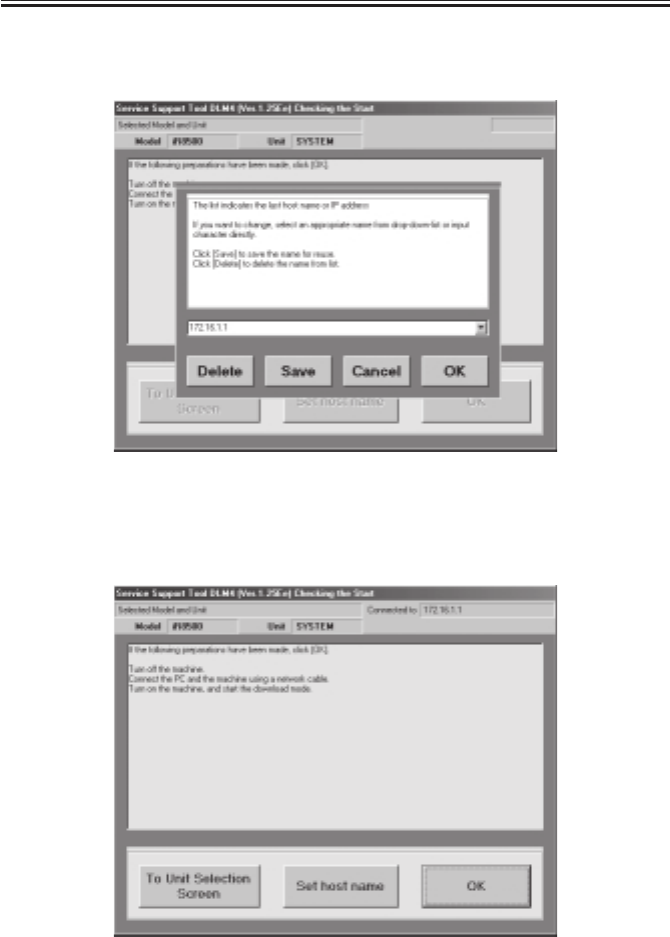
COPYRIGHT
©
2001 CANON INC. 2000 2000 2000 2000 CANON iR2200/iR2800/iR3300 REV.0 MAR. 2001
CHAPTER 7 UPGRADING
7-17 T
4) Enter the IP address or the host name (here, 172.16.1.1), and click ‘Save’. Then, click
‘OK’.
F07-104-04
5) Check to see that the notation in the upper right indicates the IP address or the host
name of the machine to connect; then, click ‘OK’ to start connection.
F07-104-05
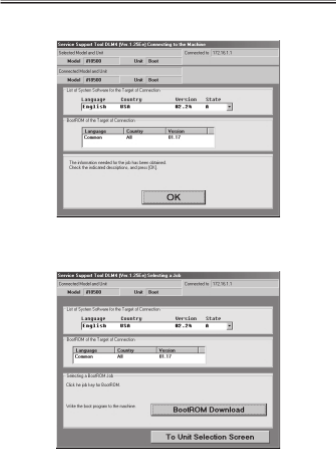
COPYRIGHT
©
2001 CANON INC. 2000 2000 2000 2000 CANON iR2200/iR2800/iR3300 REV.0 MAR. 2001
CHAPTER 7 UPGRADING
7-18 T
6) When connection is done, the following screen appears. Click ‘OK’.
F07-104-06
7) Select ‘BOOT ROM Download’ on the Service Support Tool screen.
F07-104-07
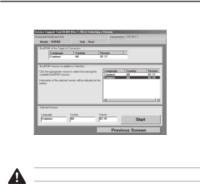
COPYRIGHT
©
2001 CANON INC. 2000 2000 2000 2000 CANON iR2200/iR2800/iR3300 REV.0 MAR. 2001
CHAPTER 7 UPGRADING
7-19 T
8) Select the files for the version in question of the Service Support Tool from ‘list of soft-
ware’; then, click ‘Start’ to start downloading.
F07-104-08
9) See the progress bar, which indicates the progress of downloading.
Take full care so that the machine and the PC will not be turned off while
downloading is taking place. Otherwise, they may fail to start up.
10) When downloading ends, turn off the PC by making the following selections: OK>To
Unit Selection Screen>OK>To Main Menu>Ending the Service Support Tool>End.
1.4.4 After Downloading
1) Turn off the machine’s main power switch, and disconnect the power plug.
2) Turn off the PC.
3) Disconnect the network cable (cross cable) and the PC from the machine.
4) If a network cable is connected, connect it to the correct location, and turn on the
machine’s main power switch.
5) When the machine has started up, start service mode, and check the version of the
BOOT ROM: COPIER>DISPLAY>VERSION>BOOT-ROM.

COPYRIGHT
©
2001 CANON INC. 2000 2000 2000 2000 CANON iR2200/iR2800/iR3300 REV.0 MAR. 2001
CHAPTER 7 UPGRADING
7-20 T
1.5 Formatting the HDD
If you have replaced the HDD, you must format it and then download the system soft-
ware, RUI, and language.
1.5.1 Making Connections
The discussions that follow assume the use of a parallel cable:
1) Using a parallel cable, connect the PC to the parallel connector on the left side of the
controller.
• At this time, the PC must remain OFF.
• Connect the 25-pin connector of the bi-Centronics cable to the PC and the 36-pin con-
nector to the machine.
2) Turn on the PC, and start up the Service Support Tool.
3) Connect the machine’s power plug to the power outlet; while holding down ‘2’ and ‘8’
of the keypad at the same time, turn on the main power switch.
1.5.2 Starting Formatting
1) Under ‘Downloading/Uploading’, select ‘To Next’.
F07-105-01
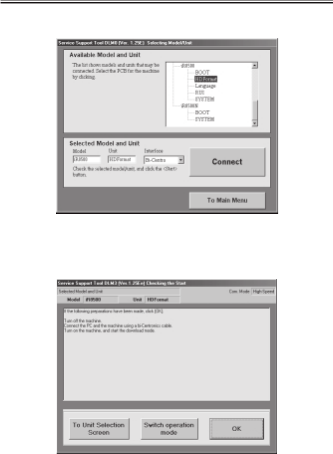
COPYRIGHT
©
2001 CANON INC. 2000 2000 2000 2000 CANON iR2200/iR2800/iR3300 REV.0 MAR. 2001
CHAPTER 7 UPGRADING
7-21 T
2) Select ‘HD Format’, and select ‘Connect’.
F07-105-02
3) At this time, if the notation in the upper right of the screen is ‘High-Speed’, go to step
5); if ‘Low-Speed’, go to step 4).
F07-105-03
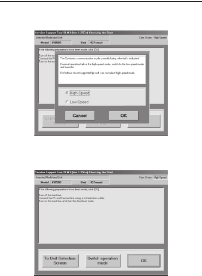
COPYRIGHT
©
2001 CANON INC. 2000 2000 2000 2000 CANON iR2200/iR2800/iR3300 REV.0 MAR. 2001
CHAPTER 7 UPGRADING
7-22 T
4) Click ‘change operation mode’ so that the Centronics Communication Mode change
screen will appear. Select ‘high-speed’, and click ‘OK’; then, go to step 6).
F07-105-04
5) Click ‘OK’ to start connection.
F07-105-05
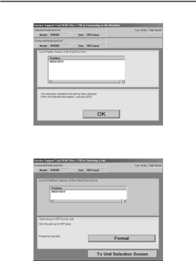
COPYRIGHT
©
2001 CANON INC. 2000 2000 2000 2000 CANON iR2200/iR2800/iR3300 REV.0 MAR. 2001
CHAPTER 7 UPGRADING
7-23 T
6) When connection is done, the following screen will appear. Select ‘OK’.
F07-105-06
7) When the Check screen appears, select ‘Format’.
F07-105-07
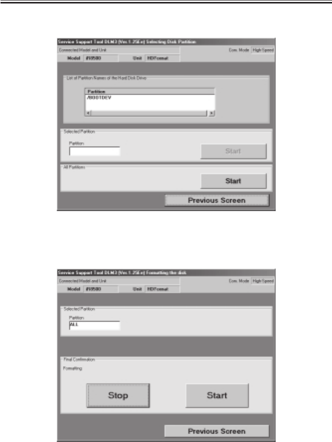
COPYRIGHT
©
2001 CANON INC. 2000 2000 2000 2000 CANON iR2200/iR2800/iR3300 REV.0 MAR. 2001
CHAPTER 7 UPGRADING
7-24 T
8) When the Start Check screen appears, select ‘Start’ to format all partitions.
F07-105-08
9) When the Start Check screen appears once again, select ‘Start’.
F07-105-09
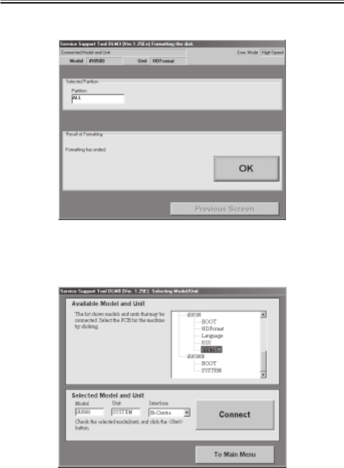
COPYRIGHT
©
2001 CANON INC. 2000 2000 2000 2000 CANON iR2200/iR2800/iR3300 REV.0 MAR. 2001
CHAPTER 7 UPGRADING
7-25 T
10) When formatting is done, the message “Format Finished” appears. Click ‘OK’.
F07-105-10
11) To continue downloading system, select ‘To Unit Selection Screen’, and click ‘OK’.
Then, start downloading system.
F-07-105-11
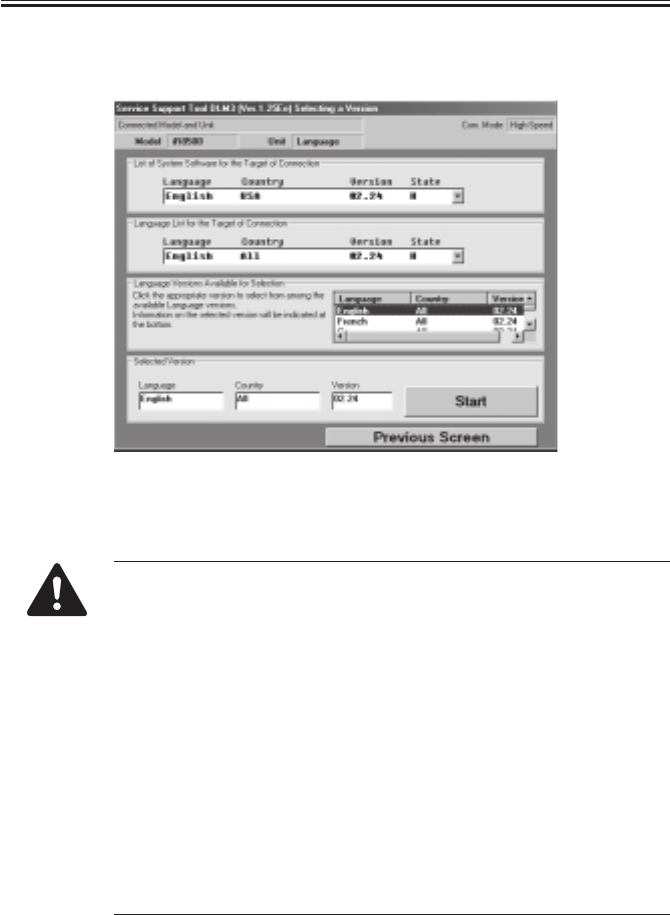
COPYRIGHT
©
2001 CANON INC. 2000 2000 2000 2000 CANON iR2200/iR2800/iR3300 REV.0 MAR. 2001
CHAPTER 7 UPGRADING
7-26 T
12) When the system downloading ends, install the RUI and the Language module in the
same way.
F07-105-12
1.5.3 Points to Note When Formatting the Hard Disk
1. If you have formatted the hard disk, you must also download the system
software at the same time. Otherwise, ‘E602-0002’ will be indicated
when you turn on the power.
If the system software is yet to be installed to the hard disk, the hard disk
may still be formatted or the system software may be downloaded in
download mode.
Connecting to the Network (using network cable)
2. If you want to install the Language module after installing the system
software, you must be sure that its version is compatible with the version
of the system software. If you install a Language module not compatible
with the system software in question and, in addition, if that language is
selected in user mode, ‘E744-0001’ will be indicated.
3. If you installed the system software after formatting the hard disk, you
may notice a faulty image on the control panel display. This is a normal
condition, and will disappear when you turn off and then on the machine
twice.
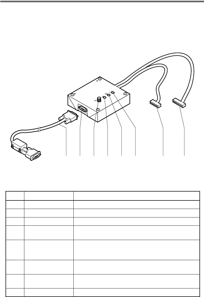
COPYRIGHT
©
2001 CANON INC. 2000 2000 2000 2000 CANON iR2200/iR2800/iR3300 REV.0 MAR. 2001
CHAPTER 7 UPGRADING
7-27 T
1.6 Downloader PCB
1.6.1 Purpose
Used for upgrading the CPU mounted on the option’s PCB (For DADF-H1/Finisher-J1).
1.6.2 Downloader PCB Components
F07-106-01
T07-106-01
[1] [2] [3] [4] [6][7][5] [8]
[1] START/STOP key
[4] Power indicating LED
Press to start or stop downloading.
[2] LOAD LED Lights when downloading is enabled.
[3] Model indicating LED Not use in this model.
Ref. Name Function
Lights when power is supplied to the downloader PCB from
the finisher.
[5] Connects the downloader PCB and the PC to each other.
Connect the cable so the ferrite core of the cable is positioned
on the PC side.
[6] Cable A (9-pin) (about
70 cm long) Not use in this model.
[7] Cable B (7-pin) (about
50 cm long) Connects the downloader PCB and the option's PCB to each
other.
[8] RS-232C connector Connects the RS-232c cable to the downloader PCB.
RS-232C cable
(totally wired straight,
9-pin)
Component names and functions
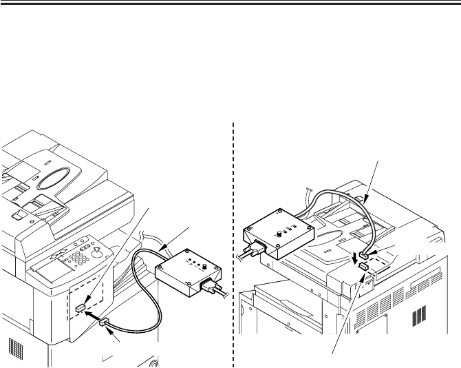
COPYRIGHT
©
2001 CANON INC. 2000 2000 2000 2000 CANON iR2200/iR2800/iR3300 REV.0 MAR. 2001
CHAPTER 7 UPGRADING
7-28 T
1.6.3 Download Procedure
a. Connecting to the option
1) Turn off the copier.
2) Detach the ADF or Finisher PCB cover.
3) Insert cable B (7pin) into ADF controller PCB (J9) or Finisher controller PCB (J12).
F07-106-02
4) Connect the RS-232C cable to the PCB and the RS-232C connector of the PC. The fer-
rite core of the cable is positioned on the PC side.
5) Turn on the copier.
The power indicating LED on the PCB light.
ADF controller PCB (J9)
DADF-H1
Cable B
Finisher controller
PCB (J12)
Finisher -J1
7-pin connector
7-pin
connector
Cable B
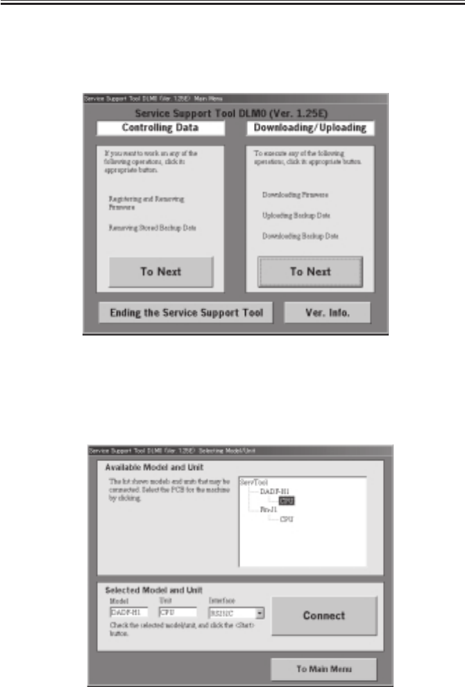
COPYRIGHT
©
2001 CANON INC. 2000 2000 2000 2000 CANON iR2200/iR2800/iR3300 REV.0 MAR. 2001
CHAPTER 7 UPGRADING
7-29 T
b. Downloading
1) Start the service support tool.
2) Choose “Downloading/Uploading.”
F07-106-03
3) Press the START/STOP key.
The LOAD LED lights.
4) Choose suitable folder.
Highlight the model name and click Connect. (ex.DADF-H1)
F07-106-04
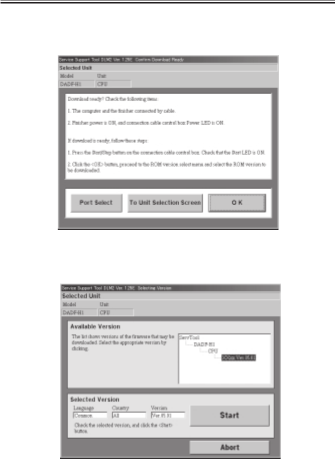
COPYRIGHT
©
2001 CANON INC. 2000 2000 2000 2000 CANON iR2200/iR2800/iR3300 REV.0 MAR. 2001
CHAPTER 7 UPGRADING
7-30 T
5) Get ready for downloading as instructed on the screen.
Click OK to proceed further.
F07-106-05
6) Choose the ROM version to download.
F07-106-06
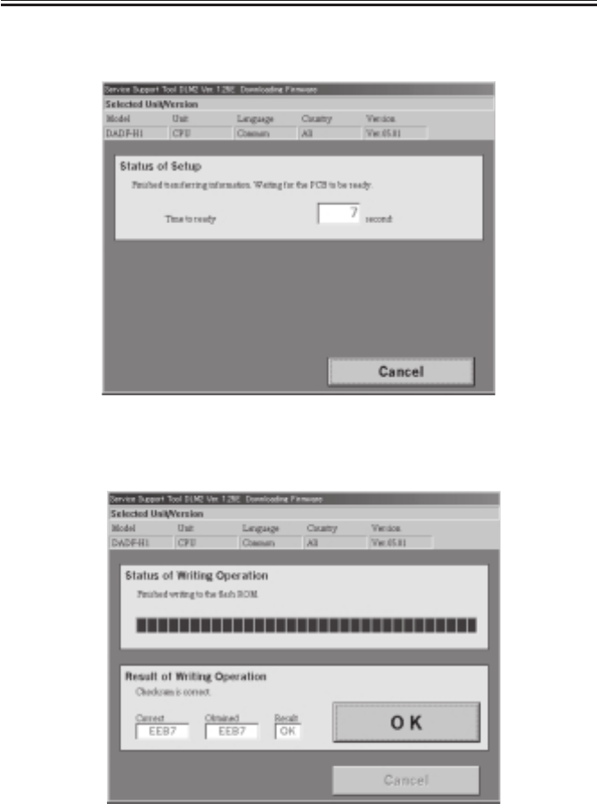
COPYRIGHT
©
2001 CANON INC. 2000 2000 2000 2000 CANON iR2200/iR2800/iR3300 REV.0 MAR. 2001
CHAPTER 7 UPGRADING
7-31 T
7) Click START to let the PC and the downloader PCB to start downloading the program.
F07-106-07
8) Click OK when the download completes.
F07-106-08
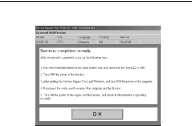
COPYRIGHT
©
2001 CANON INC. 2000 2000 2000 2000 CANON iR2200/iR2800/iR3300 REV.0 MAR. 2001
CHAPTER 7 UPGRADING
7-32 T
9) Exit as instructed on the screen.
F07-106-09
1.6.4 Disconnecting
1) Press the START/STOP key.
The LOAD LED goes off.
2) Turn off the copier.
3) Disconnect cable B from the finisher or ADF.
4) Reattach the cover to the finisher or ADF.
5) Turn on the copier

COPYRIGHT
©
2001 CANON INC. 2000 2000 2000 2000 CANON iR2200/iR2800/iR3300 REV.0 MAR. 2001
CHAPTER 7 UPGRADING
7-33 T
1.7 Upgrading by Replacing the DIMM/ROM
The following items may be upgraded by replacing the DIMM/ROM; the DIMM/ROM
will be provided as a service part on its own:
• Copier
Reader controller PCB: by replacement of flash ROM DIMM 5V; J413 [1]
DC controller PCB: by replacement of flash ROM DIMM 5V; J322 [2]
Main controller PCB: by replacement of BOOT ROM 3.3V; J1010, see MEMO [3]
Saddle Finisher-G1
Finisher controller PCB: by replacement of ROM; IC6 (DIP type) [4]
Punch driver PCB: by replacement of ROM; IC1001 (DIP type) [5]
Memo
DADF-H1/Finisher-J1
These products are updated using a personal computer.
Memo
The BOOT ROM [3] on the main controller PCB may be upgraded using a
PC. For details, see the descriptions under 1.4 “Upgrading the BOOT
ROM.”
F07-107-01
[1]
[3]
[5]
[4]
[2]

COPYRIGHT
©
2001 CANON INC. 2000 2000 2000 2000 CANON iR2200/iR2800/iR3300 REV.0 MAR. 2001
CHAPTER 7 UPGRADING
7-34 T
2 Backing Up Data
2.1 Outline
Using the Service Support Tool, you can back up the data of the SRAM mounted to the
main controller PCB.
The SRAM contains the following items of data:
• Service mode settings
• User mode settings
• Various MACHINE DATA
Once you have backed up the data, you may write it to the main controller PCB after re-
placing the PCB; or, you can simplify the work involved in entering service mode or user
mode settings.
It is recommended to back up the data whenever possible using the Service Support Tool
when you have updated the service mode settings or the user mode settings.

COPYRIGHT
©
2001 CANON INC. 2000 2000 2000 2000 CANON iR2200/iR2800/iR3300 REV.0 MAR. 2001
CHAPTER 7 UPGRADING
7-35 T
2.2 Backing Up Data
2.2.1 Making Preparations
• Install the system software to the Service Support Tool, making sure that its version is
the same as that of the machine in question.
• Check to make sure that the machine’s Data lamp is OFF.
• Turn off the machine’s main power switch, and disconnect the power plug; as necessary,
disconnect the network cable.
2.2.2 Making Connections
The discussions that follow assume the use of a parallel cable:
1) Using a parallel cable, connect the PC to the parallel connector on the right side of the
controller.
• At this time, the PC must remain OFF.
• Connect the 25-point connector of the parallel cable to the PC and the 36-pin connector
to the machine.
2) Turn on the power switch of the PC, and start up the Service Support Tool.
3) Connect the machine’s power plug to the power outlet, and turn on its main power
switch.
4) Start service mode.
5) Make the following selections so that the machine will enter download standby mode
(notation “STNDBY”): COPIER>FUNCTION>SYSTEM>DOWNLOAD.
Memo
You can select ‘network’ as the interface for data backup. Here, the use of a
bi-Centronics cable is assumed.
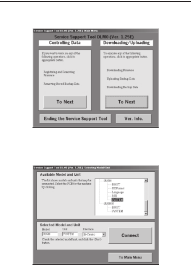
COPYRIGHT
©
2001 CANON INC. 2000 2000 2000 2000 CANON iR2200/iR2800/iR3300 REV.0 MAR. 2001
CHAPTER 7 UPGRADING
7-36 T
2.2.3 Backing Up Data
1) Under ‘Downloading/Uploading’, select ‘To Next’.
F07-202-01
2) Select ‘SYSTEM’, and select ‘Connect’. The discussions that follow assume the use of a
bi-Centronics cable as the interface.
F07-202-02
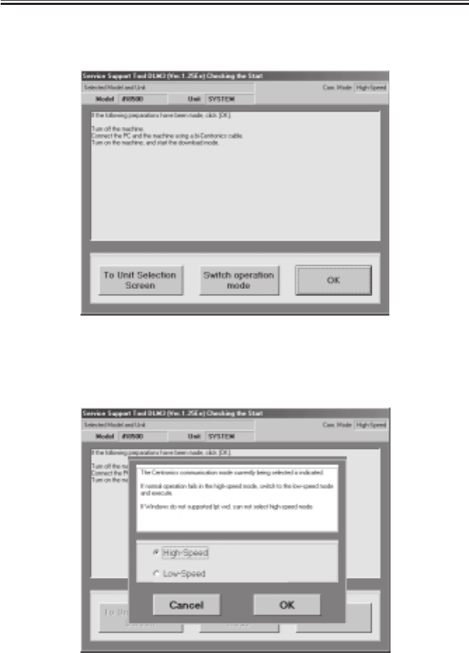
COPYRIGHT
©
2001 CANON INC. 2000 2000 2000 2000 CANON iR2200/iR2800/iR3300 REV.0 MAR. 2001
CHAPTER 7 UPGRADING
7-37 T
3) At this time, if the notation in the upper right of the screen is ‘High-Speed’, go to step
5); if ‘Low-Speed’, go to step 4).
F07-202-03
4) Click ‘Switch operation mode’ to bring up the Centronics Communication Mode
Change screen. Select ‘High-Speed’, and click ‘OK’ to move to step 5).
F07-202-04
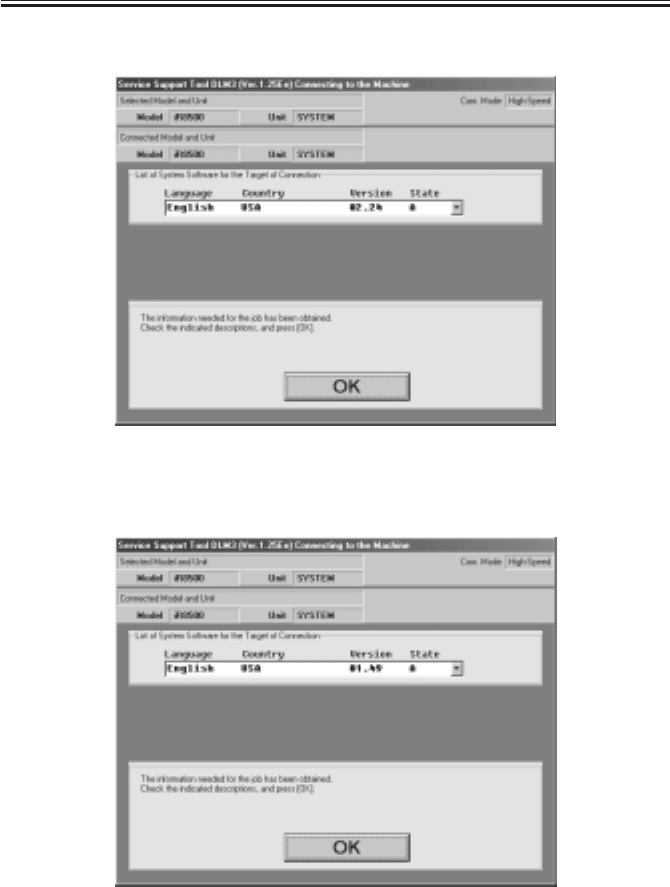
COPYRIGHT
©
2001 CANON INC. 2000 2000 2000 2000 CANON iR2200/iR2800/iR3300 REV.0 MAR. 2001
CHAPTER 7 UPGRADING
7-38 T
5) Click ‘OK’ to start connection.
F07-202-05
6) When connection is done, the following screen appears. Click ‘OK’.
F07-202-06
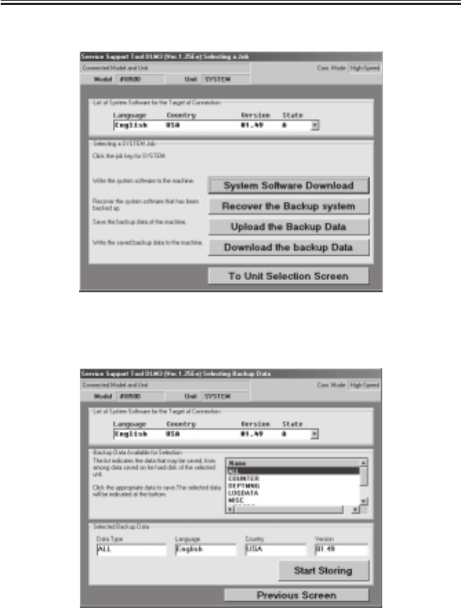
COPYRIGHT
©
2001 CANON INC. 2000 2000 2000 2000 CANON iR2200/iR2800/iR3300 REV.0 MAR. 2001
CHAPTER 7 UPGRADING
7-39 T
7) Select ‘Upload the Backup Data’ on the Service Support Tool screen.
F07-202-07
8) Select ‘ALL’, and select ‘Start Storing’.
F07-202-08
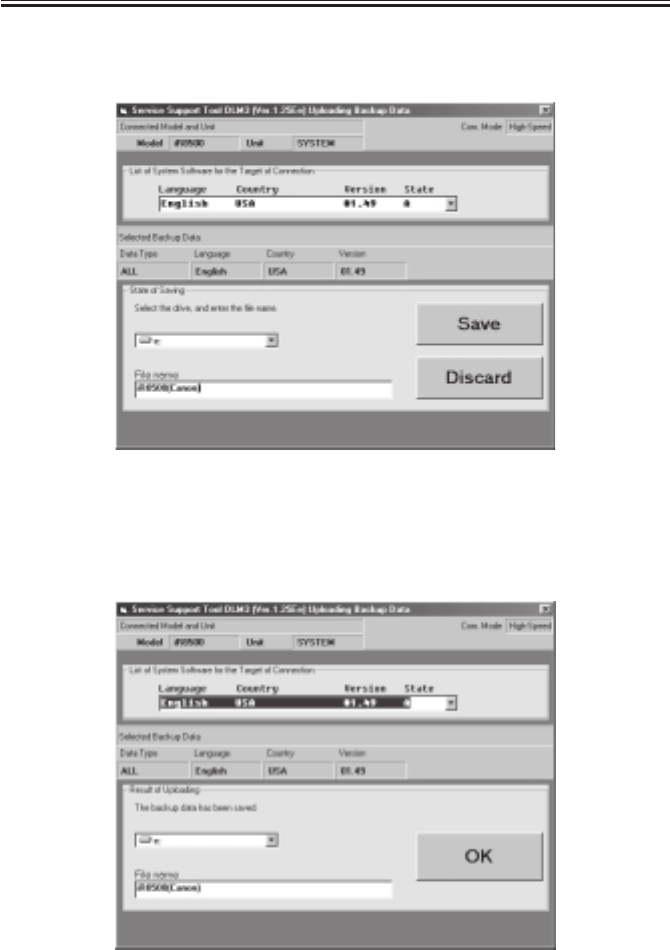
COPYRIGHT
©
2001 CANON INC. 2000 2000 2000 2000 CANON iR2200/iR2800/iR3300 REV.0 MAR. 2001
CHAPTER 7 UPGRADING
7-40 T
9) See the progress bar, indicating the progress of the save operation.
10) Select the drive to save the data to, and enter the file name; the, select ‘Save’.
F07-202-09
11) When the selected file has been stored on the selected drive, the following screen will
appear; make the following selections to end the Service Support Tool: OK>To Unit Se-
lection Screen>OK>To Main Menu>Ending the Service Support Tool>End.
F07-202-10

COPYRIGHT
©
2001 CANON INC. 2000 2000 2000 2000 CANON iR2200/iR2800/iR3300 REV.0 MAR. 2001
CHAPTER 7 UPGRADING
7-41 T
2.2.4 Downloading Backup Data
1) Under ‘Downloading/Uploading’, select ‘To Next’.
F07-202-11
2) Select ‘SYSTEM’, and select ‘Connect’.
F07-202-12

COPYRIGHT
©
2001 CANON INC. 2000 2000 2000 2000 CANON iR2200/iR2800/iR3300 REV.0 MAR. 2001
CHAPTER 7 UPGRADING
7-42 T
3) Select ‘OK’, and start connection.
F07-202-13
4) When connection is done, the following screen appears. Click ‘OK’.
F07-202-14
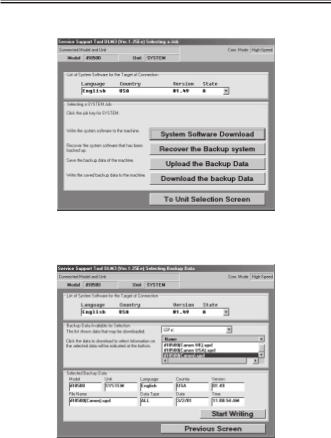
COPYRIGHT
©
2001 CANON INC. 2000 2000 2000 2000 CANON iR2200/iR2800/iR3300 REV.0 MAR. 2001
CHAPTER 7 UPGRADING
7-43 T
5) Select ‘Download the backup Data’.
F07-202-15
6) Select the file to download, and select ‘Start Writing’.
F07-202-16
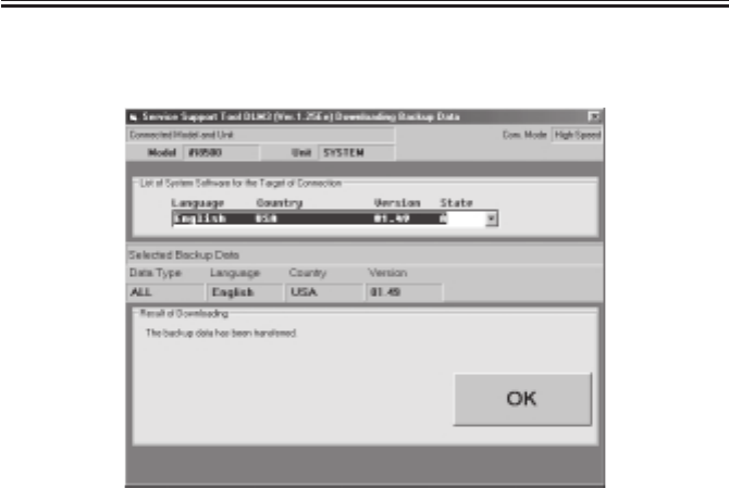
COPYRIGHT
©
2001 CANON INC. 2000 2000 2000 2000 CANON iR2200/iR2800/iR3300 REV.0 MAR. 2001
CHAPTER 7 UPGRADING
7-44 T
7) See the progress bar, indicating the progress of the downloading operation. At the end,
the following screen will appear. Select ‘OK’.
F07-202-17
8) Make the following selections to end the Service Support Tool: To Unit Selection
Screen>OK>To Main Menu>Ending the Service Support Tool>End.

COPYRIGHT
©
2001 CANON INC. 2000 2000 2000 2000 CANON iR2200/iR2800/iR3300 REV.0 MAR. 2001
CHAPTER 7 UPGRADING
7-45 T
2.2.5 Managing Backup Data
You can delete backup data that has become obsolete as follows:
You need not connect a PC to the machine to do so.
1) Under ‘Controlling Data’, select ‘To Next’.
F07-202-18
2) Select ‘Controlling Backup Data’.
F07-202-19
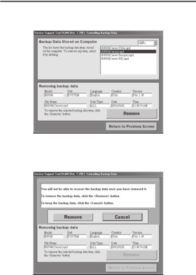
COPYRIGHT
©
2001 CANON INC. 2000 2000 2000 2000 CANON iR2200/iR2800/iR3300 REV.0 MAR. 2001
CHAPTER 7 UPGRADING
7-46 T
3) Select the file to delete from the list of ‘Backup Data Stored on Computer’; then select
‘Remove’.
F07-202-20
4) When the Delete Check screen appears, check the description for the selected file, and
select ‘Remove’.
F07-202-21

COPYRIGHT
©
2001 CANON INC. 2000 2000 2000 2000 CANON iR2200/iR2800/iR3300 REV.0 MAR. 2001
CHAPTER 7 UPGRADING
7-47 T
5) When the Delete Finish screen appears, click ‘OK’. Make the following selections to
end the Service Support Tool: Return to Previous Screen>Return to Main Menu>Ending
the Service Support Tool>End.
F07-202-22

COPYRIGHT
©
2001 CANON INC. 2000 2000 2000 2000 CANON iR2200/iR2800/iR3300 REV.0 MAR. 2001
APPENDIX
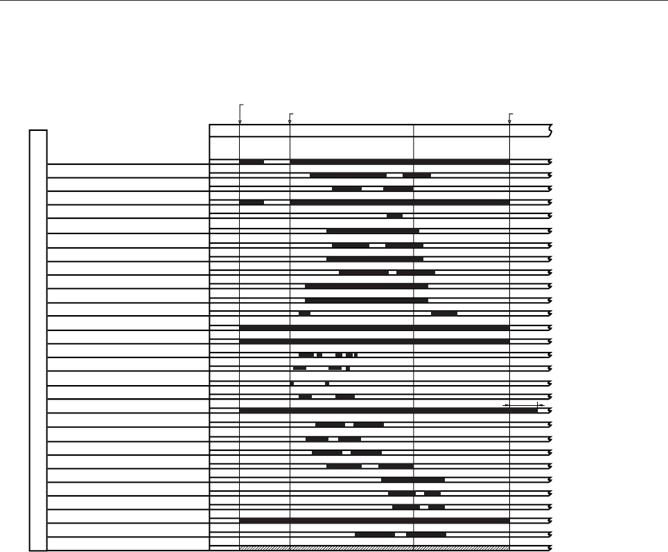
COPYRIGHT
©
2001 CANON INC. 2000 2000 2000 2000 CANON iR2200/iR2800/iR3300 REV.0 MAR. 2001
A-1
A. General Timing Chart
General Timing Chart (printer unit)
• A4, 2 sheets, Single-sided, Direct, Cassette (reversal delivery)
Main motor (M1)
Developing bias (DC)
Separation static eliminating bias
Pre-exposure lamp (LAMP2)
Transfer sheet-to-sheet interval bias
Developing clutch (CL3)
Developing bias (AC)
Primary charging bias (DC)
Primary charging bias (AC)
Separation charging bias
Transfer changing cleaning bias
Fixing main heater (H1)
Laser activation
Pickup motor (M2)
Pickup DOWN solenoid (SL1)
Cassette 1 re-try paper sensor (PS7)
Registration motor (M9)
Laser scanner motor (M10)
Registration paper sensor (PS10)
Image leading edge sensor (PS12)
Fixing / feeding sensor (PS13)
Vertical path clutch (CL1)
Pre-registration paper sensor (PS9)
No.1 delivery sensor (PS15)
No.1 delivery full sensor (PS16)
Fixing motor (M4)
Fixing film sensor (PS26)
Delivery motor (M5)
Printer Unit
PSTBY
PINTR PRINT LSTR PSTBY
Print command received
Job start command received Print end command received
Fixing sub heater(H2)
*2
*1
*1: Varies between 0 and 9 min to suit the selected silent mode shift interval.
*2: Goes ON once every 540 msec.
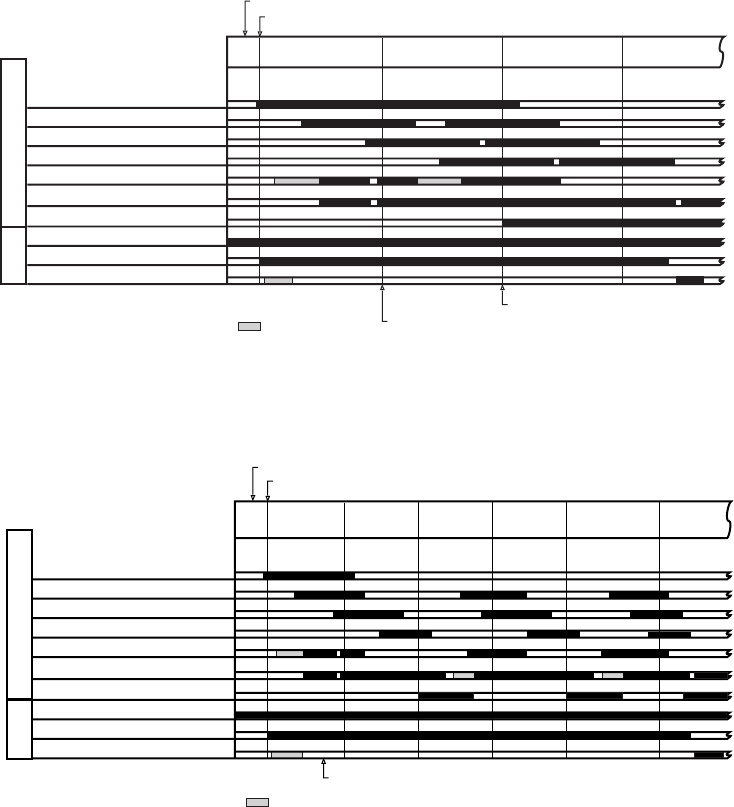
COPYRIGHT
©
2001 CANON INC. 2000 2000 2000 2000 CANON iR2200/iR2800/iR3300 REV.0 MAR. 2001
A-2
General Timing Chart (reader unit w/ ADF)
• A4, 2 sheets, Signal-sided, Direct
• A4, 1 sheet, Double-sided, Direct
Reader Unit
ADF
STBY
Original set sensor (PI10)
Registration paper sensor (PI6)
Read sensor (PI7)
Delivery reversal sensor (PI8)
Pickup motor (M2)
Main motor (M1)
Pickup DOWN solenoid (SL1)
Original placed
1st original
separated/feed
1st original read
2nd original separated/feed
1st original delivered
2nd original read
2nd original
delivered
Scanner home position sensor (PS400)
Scanning lamp (LAMP1)
Scanner motor (M400)
CCW CW
Start key ON
Print command sent
Print command sent
: motor CCW.
Reader Unit
ADF
STBY
Original set sensor (PI10)
Registration paper sensor (PI6)
Read sensor (PI7)
Delivery reversal sensor (PI8)
Pickup motor (M2)
Main motor (M1)
Pickup DOWN solenoid (SL1)
Original placed
Original
separated/feed
Original
face read Original
reversed
Original reversed
(idle feed)
Scanner home position sensor (PS400)
Scanning lamp (LAMP1)
Scanner motor (M400)
CCW CW
Start key ON
Print command sent
Original
delivered
:motor CCW.
Original
back read
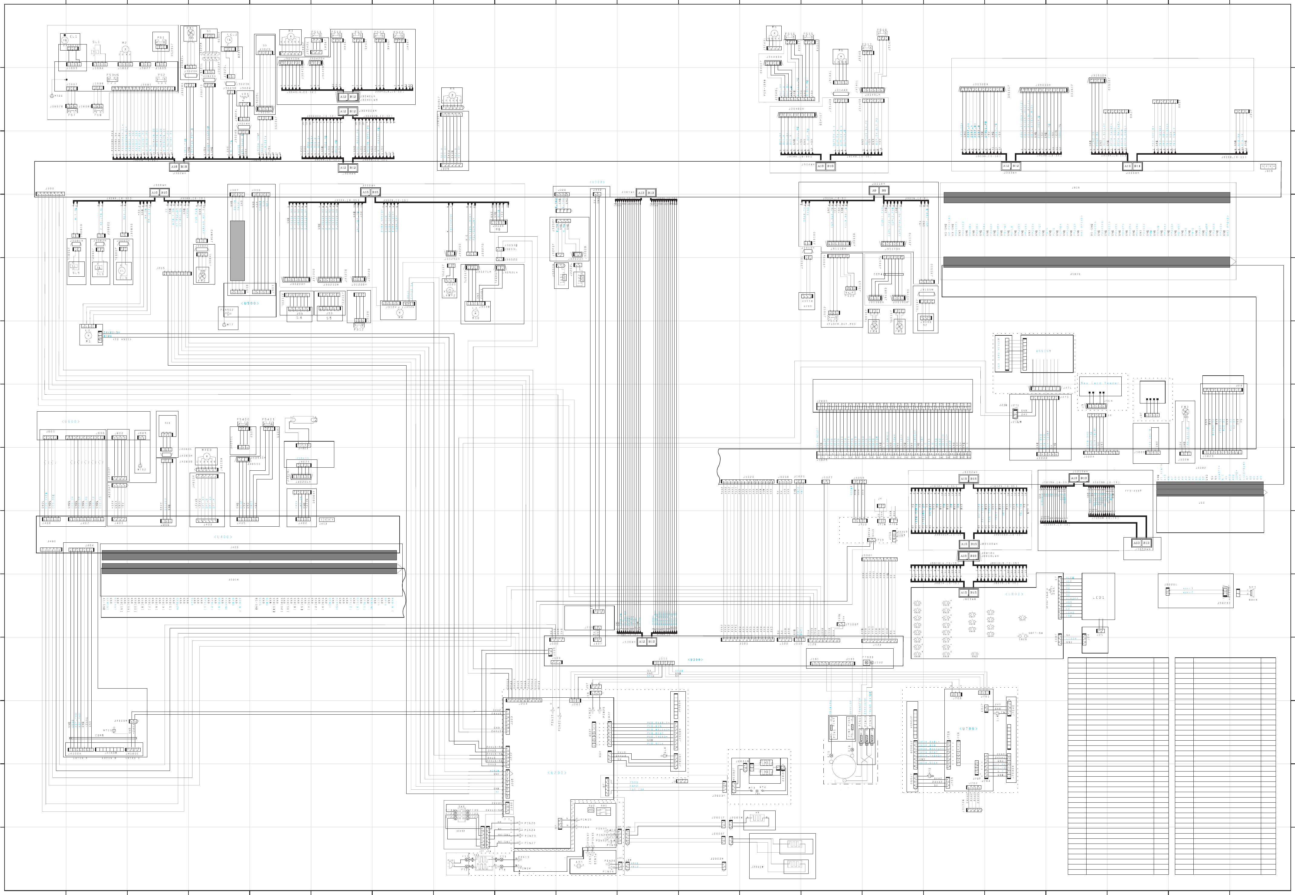
COPYRIGHT
©
2001 CANON INC. 2000 2000 2000 2000 CANON iR2200/iR2800/iR3300 REV.0 MAR. 2001
A-3
B. General Circuit Diagram
N
M
L
K
J
I
H
G
F
E
D
C
B
A
N
M
L
K
J
I
H
G
F
E
D
C
B
A
12345678912 11131415161718192021 10
12345678912 11131415161718192021 10
0VA
13VU
0VD
5V
0VU3
0VU3
24VU3
24VU 3
24V
24V
24V
J3086
LAMP 1
24VU3
0VU3
13VU3
0VA
5V
0VD
J4101F
24V
HTTRG1_ON
HTTRG2_ON
HTRLY_ON
(From 3-M)
H5
H4
5V
GND
APON
J3088
J3126
J3200M
To Super G4 FAX Board-B1
Off-hook
detection PCB
To FAX Unit
To FAX Unit
To FAX Unit
Name
BD sensor
Leakage breaker
Vertical path clutch
Multifeeder clutch
Developing clutch
Developing fan
Fixing fan
Electrical unit fan
Carl reducing 1
Carl reducing 2
Fixing main heater
Fixing sub heater
Cassette heater
Mirror heater
Lens heater
Scanning lamp
Pre-exposure lamp
Main motor
Pickup motor
Horizontal registration sensor shift motor
Fixing motor
Delivery motor
Duplex motor
Registration motor
Laser scanner motor
Scanner moter
Power supply cord
Cassette1 paper sensor
Cassette2 paper sensor
Cassette1 paper level sensor 1
Cassette1 paper level sensor 2
Cassette2 paper level sensor 1
Cassette2 paper level sensor 2
Position
13-K
14-A
20-N
18-N
20-J
18-N
18-J
2-H
7-I
7-I
9-C
9-B
9-B
9-A
9-A
17-H
14-J
20-I
20-N
17-N
15-J
9-N
8-N
14-M
14-J
18-G
14-A
19-N
19-M
20-M
20-M
20-M
20-M
Notaion
BD
CB1
CL1
CL2
CL3
FM1
FM2
FM3
FM4
FM5
H1
H2
H3
H4
H5
LAMP1
LAMP2
M1
M2
M3
M4
M5
M6
M9
M10
M400
PLG1
PS1
PS2
PS3
PS4
PS5
PS6
Name
Cassette1 re-try paper sensor
Cassette2 re-try paper sensor
Pre-registration paper sensor
Registration paper sensor
Horizontal registration paper sensor
Image leading edge sensor
Fixing/feeding sensor
No.1 delivery sensor
No.1 delivery full sensor
Duplex unit inlet paper sensor
Duplex unit outlet paper sensor
Multifeeder paper sensor
Right cover open/close sensor
Fixing film sensor
Scanner home position sensor
Copyboard cover sensor
Toner sensor
Waste toner case full sensor
Environment sensor
Cassette1 size sensor
Cassette2 size sensor
Original sensor
Pickup DOWN solenoid
Multifeeder holding plate releasing solenoid
Charging roller solenoid
Speaker
Main power switch
Environment heater switch
Front cover switch
Main thermister
Sub thermister
Thermal switch
Multifeeder paper width sensor
Position
20-M
20-M
16-N
16-N
16-N
16-I
8-J
8-N
9-N
7-N
7-N
15-N
15-N
8-J
18-H
17-H
18-N
6-I
17-N
17-J
16-J
19-H
20-N
20-J
20-J
1-E
12-B
12-B
14-B
12-J
12-J
9-B
18-M
Notation
PS7
PS8
PS9
PS10
PS11
PS12
PS13
PS15
PS16
PS17
PS18
PS22
PS23
PS26
PS400
PS401
S1
S2
S3
S4
S5
SD1
SL1
SL5
SL6
SP1
SW1
SW2
SW3
TH1
TH2
TP1
VR1
Composite power supply PCB
Main power supply PCB
Switch PCB
Switch PCB
DC controller PCB
Thermistor separation power
supply PCB (200V model only)
Reader controller PCB
Pickup PCB
Laser driver PCB
Control Panel PCB
CCD PCB
Inverter PCB
(100V ONLY)
Main controller PCB (1/2)
<U1000>
To DADF-H1
To 2-Cassette Feeding Unit-W1
To FAX Unit
Fixing Unit
<INV1>
Inverter
PCB
To Side Paper Deck-L1
To Finisher-J1
To Saddle Finisher-G1
(From 3-M)
(From 1-M)
Counter PCB
Software ID PCB
Centronics PCB
To Inner 2-way Tray-A1
To Inner 2-way Tray-A1
or
Relay delivery unit
To Delivery Unit
To 6-C
(Side Paper Deck-L1)
To 12-C
(2-Cassette Feeding Unit-W1) To 6-B
(Saddle Finisher-G1)
Main controller PCB (2/2)
<U1000>
HDD (2.5INCH)
CC-IV N
(accessory)
(accessory)
(accessory)
From FAX Unit
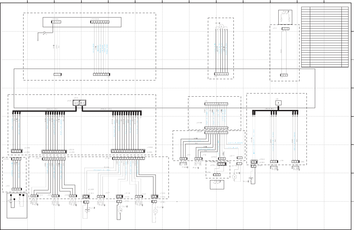
COPYRIGHT
©
2001 CANON INC. 2000 2000 2000 2000 CANON iR2200/iR2800/iR3300 REV.0 MAR. 2001
A-5
13 12 11 10 9 8 7 6 5 4 3 2 1
H
G
F
E
D
C
B
A
LED100D SW100D
POPD*
Side deck drier PCB
Lattice connector
Name
Deck feeding clutch
Deck pickup clutch
Deck open indication
Deck main motor
Deck lifter motor
Deck pickup sensor
Deck paper absent sensor
Deck lifter upper limit sensor
Deck lifter position sensor
Deck set sensor
Deck feed sensor
Deck paper level sensor
Deck paper supply position sensor
Deck open sensor
Deck pickup roller releasing solenoid
Deck open solenoid
Deck open switch
Deck open detecting switch
Deck lifter lower limit detecting switch
Position
9-A
8-A
13-A
5-H
5-B
8-A
12-A
11-A
11-A
3-C
10-A
6-C
7-C
3-C
10-A
4-B
13-A
3-H
5-B
Notation
CL1D
CL2D
LED100D
M1D
M2D
PS1D
PS2D
PS3D
PS4D
PS5D
PS6D
PS7D
PS8D
PS9D
SL1D
SL2D
SW100D
SW1D
SW2D
C. Side Paper Deck-L1 General Circuit Diagram
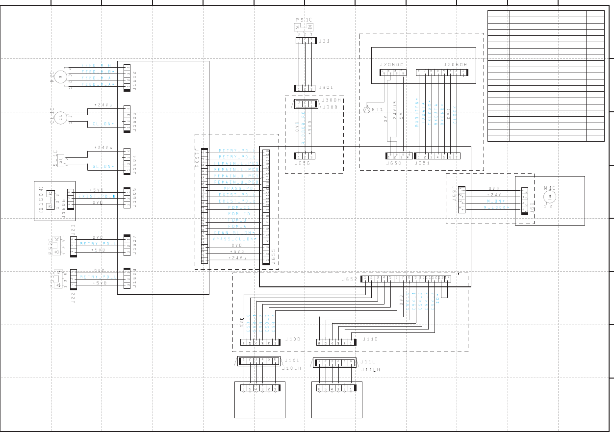
COPYRIGHT
©
2001 CANON INC. 2000 2000 2000 2000 CANON iR2200/iR2800/iR3300 REV.0 MAR. 2001
A-6
D. 2-Cassette Feeding Unit-W1 General Circuit Diagram
12 11 10 9 8 7 6 5 4 3 2 1
H
G
F
E
D
C
B
A
S1C S2C
(Q1603,1605-1609)
Lattice connector
Cassette pickup PCB
Pedestal controller PCB
Name
Vertical path roller clutch
Pedestal main motor
Cassette pickup motor
Right cover open/closed sensor
Cassette3 re-try paper sensor
Cassette4 re-try paper sensor
Vertical path paper sensor
Cassette3 paper sensor
Cassette4 paper sensor
Cassette3 paper level sensor0
Cassette3 paper level sensor1
Cassette4 paper level sensor0
Cassette4 paper level sensor1
Cassette3 size detecting switch
Cassette4 size detecting switch
Pickup roller DOWN solenoid
Position
11-F
2-E
11-G
6-H
11-D
11-C
9-E
12-E
9-E
9-E
9-E
9-E
9-E
7-A
6-A
11-F
Notation
CL1C
M1C
M2C
PS1C
PS2C
PS3C
Q1603
Q1604
Q1605
Q1606
Q1607
Q1608
Q1609
S1C
S2C
SL1C

COPYRIGHT
©
2001 CANON INC. 2000 2000 2000 2000 CANON iR2200/iR2800/iR3300 REV.0 MAR. 2001
A-7
E. Inner 2-Way Tray-A1 General Circuit Diagram
1110987654321
H
I
J
K
G
F
E
D
C
B
A
Name
2-way delivery inlet motor
2-way delivery outlet motor
No.2 delivery sensor
No.2 delivery full sensor
No.3 delivery sensor
2-way delivery open/closed sensor
2-way delivery solenoid
Position
10-H
6-H
3-G
8-G
8-G
4-G
2-K
Notation
M7B
M8B
PS19B
PS20B
PS21B
PS24B
SL3B
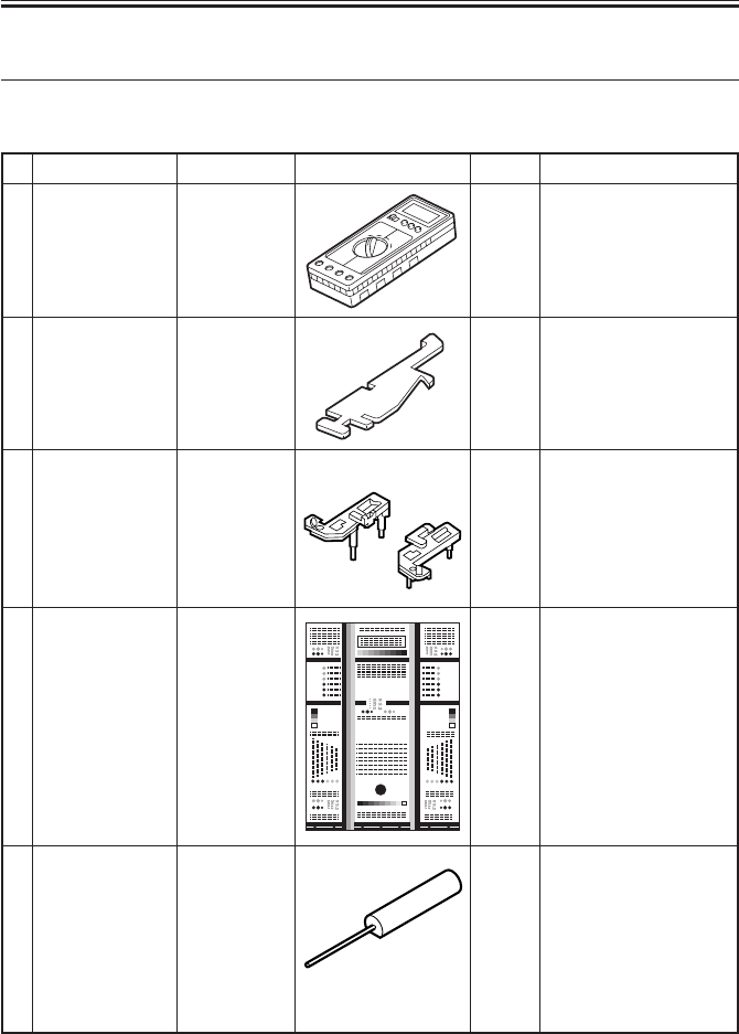
COPYRIGHT
©
2001 CANON INC. 2000 2000 2000 2000 CANON iR2200/iR2800/iR3300 REV.0 MAR. 2001
APPENDIX
A-8
Remarks
Used when making
electrical checks.
Used when positioning
the No. 1/No. 2 mirror.
Used when adjusting/
checking images.
Used when making
electrical checks.
No.
1
2
3
4
5
Name
Digital
multimeter
Door switch
Mirror
positioning tool
(front, rear)
NA-3 Test Sheet
Tester extension
pin
Toll No.
FY9-2002
TKN-0093
FY9-3009
FY9-9196
FY9-3038
Shape Rank
A
A
B
A
A
F. List of Special Tools
The following special tools will be needed in addition to the standard tools set:

COPYRIGHT
©
2001 CANON INC. 2000 2000 2000 2000 CANON iR2200/iR2800/iR3300 REV.0 MAR. 2001
APPENDIX
A-9
Remarks
Used when making
electrical checks.
No.
6
Name
Tester extension
pin (L-shaped)
Toll No.
FY9-3039
Shape Rank
A
Rank:
A: each service person is expected to carry one.
B: each group of five persons is expected to carry one.
C: each workshop is expected to carry one.

COPYRIGHT
©
2001 CANON INC. 2000 2000 2000 2000 CANON iR2200/iR2800/iR3300 REV.0 MAR. 2001
APPENDIX
A-10
No.
1
2
3
4
5
6
G. List of Solvents/Oils
Name
Alcohol
Solvent
Heat resisting
grease
Lubricant
Lubricant
Lubricant
Uses
Cleaning:
e.g., glass, plastic,
rubber parts;
external covers.
Cleaning:
metal part; oil,
toner.
Lubrication: fixing
drive parts
Lubrication: drive
parts, friction parts
Lubrication: scanner
rail
Composition
Fluorescent family
hydrocarbon,
alcohol, surface
activating agent,
water
Fluorescent family
hydrocarbon,
chlorine family
hydrocarbon,
alcohol.
Mineral family
lithium soap,
molybdenum
disulfide,
Mineral oil
(paraffin family)
Silicone oil
Silicone oil
Remarks
• Do not bring near fire.
• Procure locally.
• Substitute: IPA (isopropyl alcohol)
• Do not bring near fire.
• Procure locally.
Tool No.: CK-0427 (500g/can)
Tool No.: CK-0524 (100cc)
Tool No.: CK-0551 (20g)
Tool No.: FY9-6011 (50cc)
Prepared by
Office Imaging Products Quality Assurance Center
CANON INC.
Printed in U.S.A.
REVISION 0 (MAR. 2001) (18723/18756/22109/32205/35338)
5-1, Hakusan 7-chome, Toride-shi, Ibaraki 302-8501 Japan
COPYRIGHT
©
2001 CANON INC. CANON iR2200/iR2800/iR3300 REV.0 MAR. 2001 PRINTED IN U.S.A.

PRINTED IN U.S.A. (IMPRIME AU U.S.A.) 0401M0.7-1
This publication is
printed on 100%
recycled paper.
