Canon Dr 4010C Users Manual User
Canon-Imageformula-Dr-4010C-Color-Departmental-Scanner-Owners-Manual-587327 canon-imageformula-dr-4010c-color-departmental-scanner-owners-manual-587327
If not then dr_4010c_user_manual Manual: ://s.canon.com/cpr/pdf/Manuals/dr_4010c_user_manual
DR-4010C 4010UM
DR-4010C to the manual 26527884-73f5-4d21-bad7-ff34da85ecad
2015-01-23
: Canon Canon-Dr-4010C-Users-Manual-242548 canon-dr-4010c-users-manual-242548 canon pdf
Open the PDF directly: View PDF ![]() .
.
Page Count: 142 [warning: Documents this large are best viewed by clicking the View PDF Link!]
- DR-4010C User Manual
- Hardware
- Contents
- Chapter 1 Before Using the Scanner
- Chapter 2 Setup
- Chapter 3 Basic Operation
- Chapter 4 Maintenance
- Chapter 5 Troubleshooting
- Chapter 6 Appendix
- Software
- Hardware
Document Scanner
User Manual
Please read this manual before operating this scanner.
After you finish reading this manual, store it in a safe
place for future reference.

International ENERGY STAR Program
As an ENERGY STAR® Partner, Canon Electronics Inc., has determined that this machine meets
the ENERGY STAR® Program guidelines for energy efficiency.
The International ENERGY STAR® Office Equipment Program is an international program that
promotes energy saving through the use of computers and other office equipment. The program
backs the development and dissemination of products with functions that effectively reduce
energy consumption. It is an open system in which business proprietors can participate
voluntarily. The targeted products are office equipment, such as computers, monitors, printers,
fax, machine, copiers, and scanners. The standards and logos are uniform among participating
nations.
Trademarks
• Canon and the Canon logo are registered trademarks of Canon Inc. in the United States and may also be trademarks or
registered trademarks in other countries.
• Microsoft and Windows are registered trademarks of Microsoft Corporation in the United States and other countries.
• ISIS is a trademark of EMC Corporation, in the United States.
• Intel and Pentium are registered trademarks of Intel Corporation.
•ENERGY STAR
® is a U.S. registered mark.
• Adobe is the registered trademark of Adobe Systems Incorporated in the United States and/or other countries.
• Adaptec is registered trademark of Adaptec Inc.
• Other product and company names herein may be the trademarks of their respective owners.
Copyright
Copyright 2006 by CANON ELECTRONICS INC. All rights reserved.
No part of this publication may be reproduced or transmitted in any form or by any means, electronic or
mechanical, including photocopying and recording, or by any information storage or retrieval system without the
prior written permission of CANON ELECTRONICS INC.
Disclaimers
The information in this document is subject to change without notice.
CANON ELECTRONICS INC. MAKES NO WARRANTY OF ANY KIND WITH REGARD TO THIS MATERIAL,
EITHER EXPRESS OR IMPLIED, EXPECT AS PROVIDED HERE IN, INCLUDING WITHOUT LIMITATION,
THERE OF, WARRANTIES AS TO MARKETABILITY, MERCHANTABILITY, FITNESS FOR A PARTICULAR
PURPOSE OF USE OR NON-INFRINGEMENT. CANON ELECTRONICS INC. SHALL NOT BE LIABLE FOR
ANY DIRECT, INCIDENTAL, OR CONSEQUENTIAL DAMAGES OF ANY NATURE, OR LOSSES OR EXPENSES
RESULTING FROM THE USE OF THIS MATERIAL.

INTRODUCTION
i
INTRODUCTION
Thank you for purchasing the Canon DR-4010C Document Scanner. Please read this manual
thoroughly before using the scanner to familiarize yourself with its capabilities, and to make the most
of its many functions. After reading this manual, store it in a safe place for future reference.
Manuals for the Scanner
The User Manual is divided into two sections: Hardware and Software. The Hardware section
contains general information and instructions for using the scanner. The Software section explains
how to make settings for the software required to use the scanner.
Hardware
Chapter 1 Before Using the Scanner
Safety instructions, features, scanner parts
Chapter 2 Setup
Scanner operation environment and setup procedures
Chapter 3 Basic Operation
Supported document types, basic scanning procedure, steps for clearing a paper jam
Chapter 4 Maintenance
Procedures for regular maintenance, roller replacement
Chapter 5 Troubleshooting
Troubleshooting information, application uninstall procedure
Chapter 6 Appendix
Product specifications and dimensional drawings
Software
Chapter 7 ISIS/TWAIN Driver Settings
ISIS/TWAIN driver settings
Chapter 8 Job Registration Tool Settings
Job Registration Tool settings
Chapter 9 Practical Examples
Hints and additional information about ISIS/TWAIN driver settings

INTRODUCTION
ii
Symbols Used in This Manual
The following symbols are used in this manual to explain procedures, restrictions, handling
precautions, and instructions that should be observed for safety.
WARNING
Indicates a warning concerning operations that may lead to death or injury to persons
if not performed correctly. To use the machine safely, always pay attention to these
warnings.
CAUTION
Indicates a caution concerning operations that may lead to injury to persons, or
damage to property if not performed correctly. To use the machine safely, always pay
attention to these cautions.
IMPORTANT
Indicates operational requirements and restrictions. Be sure to read these items carefully to
operate the machine correctly, and avoid damage to the machine.
Note
Indicates a clarification of an operation, or contains additional explanations for a procedure.
Reading these notes is highly recommended.
(See “Documents,” on p. 3-1)
Shows the page number and title of a section that contains related information. Click to go to
the indicated page.

Document Scanner
User Manual
Hardware

Contents
ii
Contents
Chapter 1 Before Using the Scanner ........................................................................1-1
1-1 Important Safety Instructions ..................................................................1-1
Installation Location.....................................................................................1-1
Power ..........................................................................................................1-2
Moving the Scanner ....................................................................................1-2
Handling ......................................................................................................1-3
Disposal.......................................................................................................1-4
1-2 Features of the DR-4010C Document Scanner.......................................1-5
1-3 Names and Functions of Parts.................................................................1-7
Chapter 2 Setup ..........................................................................................................2-1
2-1 Setup Procedure........................................................................................2-1
2-2 Installation Requirements ........................................................................2-2
2-3 Installing the Software ..............................................................................2-4
Setup Disc ...................................................................................................2-4
Software Installation ....................................................................................2-5
2-4 Connecting the Scanner to the Computer ............................................2-11
Using a USB Connection...........................................................................2-11
Using a SCSI Connection..........................................................................2-12
2-5 Turning the Power ON.............................................................................2-14
Scanner Recognition .................................................................................2-14
Chapter 3 Basic Operation.........................................................................................3-1
3-1 Documents.................................................................................................3-1
3-2 Document Feed and Eject Tray ................................................................3-3
Preparing the Document Feed Tray.............................................................3-3
Preparing the Document Eject Tray.............................................................3-3
3-3 Placing Documents ...................................................................................3-5
Feeding in the Page Separation Mode ........................................................3-5
Feeding in the Bypass Mode.......................................................................3-7
3-4 Job Function..............................................................................................3-9
What is the Job Function ?..........................................................................3-9
Job Registration Tool.................................................................................3-10
Scanning With the Job Function................................................................3-10
About Launcher .........................................................................................3-11
3-5 CapturePerfect 3.0...................................................................................3-16
What is CapturePerfect 3.0 .......................................................................3-16
Using CapturePerfect 3.0 ..........................................................................3-17
Scan Panel ................................................................................................3-21
3-6 Using Patchcode Sheets.........................................................................3-23
About Patchcode Sheets ...........................................................................3-23
Patchcode Pattern Function ......................................................................3-24
How to Use Patchcode Sheets..................................................................3-24
3-7 Clearing a Paper Jam..............................................................................3-26
3-8 Other Functions.......................................................................................3-29
Folio Scan..................................................................................................3-29
Double Feed Detection Function ...............................................................3-30
Long Document Mode ...............................................................................3-30
MultiStream Function ................................................................................3-34
Chapter 4 Maintenance...............................................................................................4-1
4-1 Regular Maintenance ................................................................................4-1
Cleaning the Scanner..................................................................................4-1
Cleaning the Feed Path...............................................................................4-1
Cleaning the Sensor Glass and the Rollers ................................................4-2
4-2 Removing and Attaching the Rollers.......................................................4-5
Roller Replacement Cycle...........................................................................4-5

Contents
iii
Resetting the Counter .................................................................................4-6
Removing/Attaching the Roller Unit ............................................................4-9
Removing and Attaching the Retard Roller ...............................................4-11
Chapter 5 Troubleshooting ........................................................................................5-1
5-1 Troubleshooting ........................................................................................5-1
5-2 Uninstalling Software................................................................................5-6
Uninstalling the ISIS/TWAIN Driver .............................................................5-7
Uninstalling the Job Registration Tool ......................................................... 5-8
Uninstalling CapturePerfect 3.0 .................................................................5-10
Chapter 6 Appendix ....................................................................................................6-1
6-1 Specifications ............................................................................................6-1
Specifications ..............................................................................................6-1
Replacement Parts......................................................................................6-2
Options ........................................................................................................6-2
External Dimensions ...................................................................................6-3
Index ................................................................................................................................6-4
1-1
Chapter 1
Before Using the Scanner
1-1 Important Safety Instructions
To ensure the safe operation of this scanner, be sure to read the safety warnings and precautions
described below.
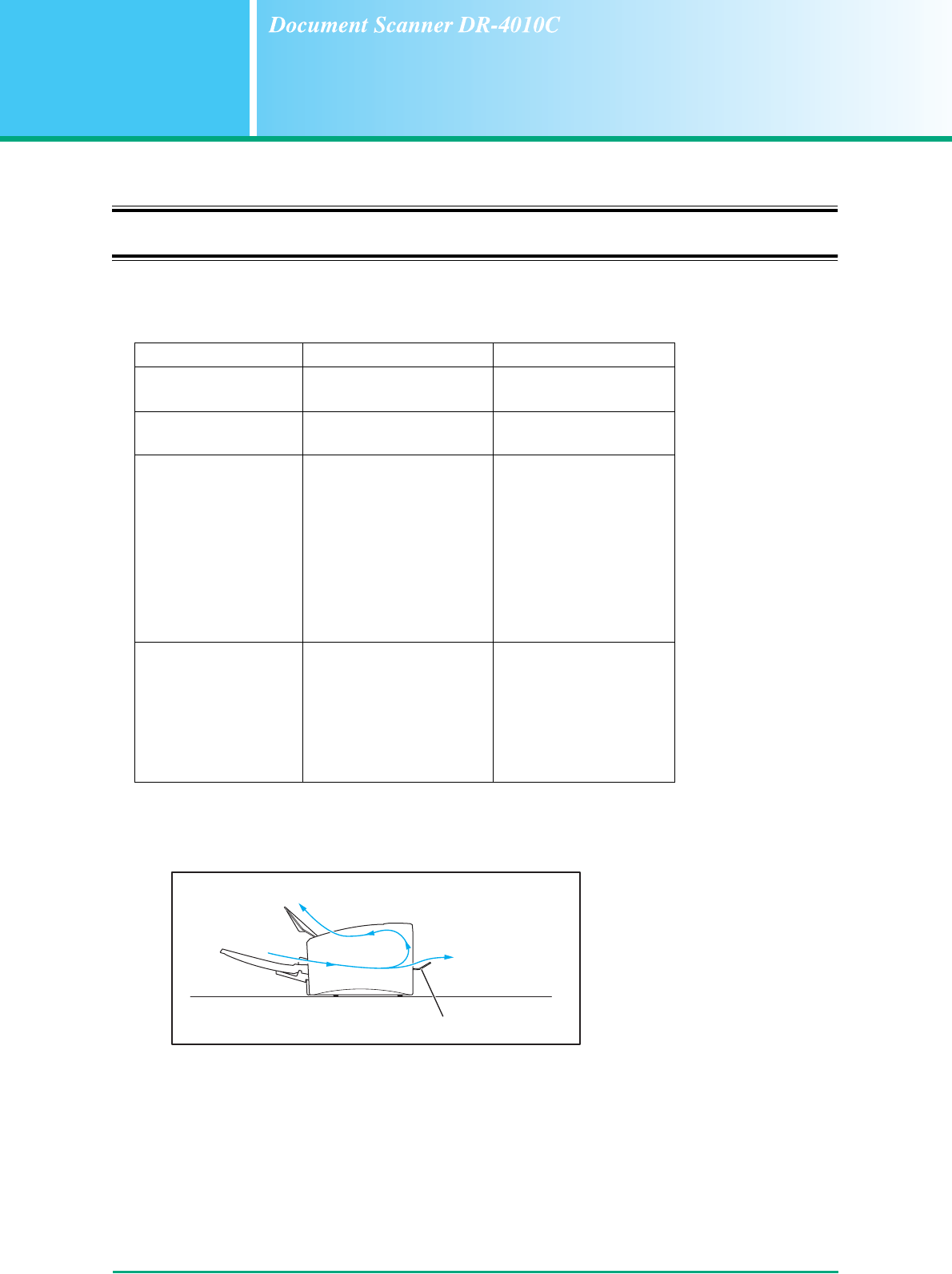
Installation Location
The performance of this scanner is affected by the environment in which it is installed. Make sure
that the location where the scanner is installed meets the following environmental requirements.
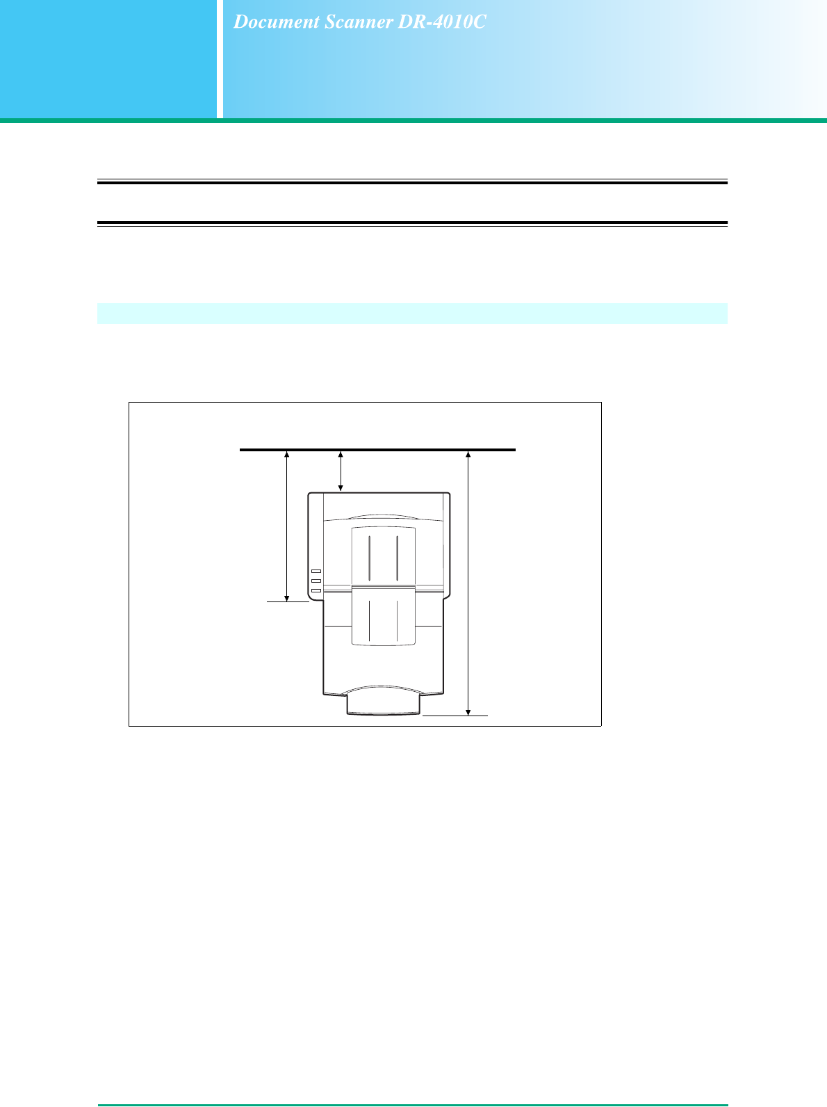
• Provide adequate space around the scanner for operation, maintenance, and ventilation.
• If scanned documents are ejected to the back tray of the scanner, provide adequate space behind
the scanner for documents ejected after being scanned. (See “Preparing the Document Eject
Tray,” on p. 3-3.)
• Avoid installing the machine in direct sunlight. If this is unavoidable, use curtains to shade the
scanner.
• Avoid locations where a considerable amount of dust accumulates.
• Avoid warm or humid locations, such as in the vicinity of a water faucet, water heater, or humidifier.
• Avoid locations where ammonia gas is emitted.
• Avoid locations near volatile or flammable materials, such as alcohol or paint thinner.
• Avoid locations that are subject to vibration.
15.7" (400 mm)
when the document
feed tray and
document feed tray
extension are
closed.
At least 3.9" (100 mm)
when eject tray is empty.
25.6" (650 mm)
when the document
feed tray and
document feed tray
extension are
open.
Chapter 1 Before Using the Scanner
1-2
• Avoid exposing the scanner to rapid changes in temperature. If the room in which the scanner is
installed is cold but rapidly heated, water droplets (condensation) may form inside the scanner.
This may result in a noticeable degradation in scanning quality.
The following conditions are recommended for optimal scanning quality:
Room temperature: 10 °C to 32.5 °C (50 °F to 90.5 °F)
Humidity: 20% to 80% RH
• Avoid installing the scanner near equipment that generates a magnetic field (e.g. speakers,
televisions, or radios.)
Power
• Connect only to a power outlet of the rated voltage and power supply frequency. (120 V, 60 Hz or
220-240 V, 50/60 Hz depending on your region)
• Do not use a power supply that is not rated for the specified voltage. Doing so might cause a fire or
electric shock.
• Do not connect other electrical equipment to the same power outlet to which the scanner is
connected. Also, when using an extension cord, make sure that the extension cord is rated for the
current requirements of the scanner.
• The power cord may become damaged if it is often stepped on or if heavy objects are placed on it.
Continued use of a damaged power cord can lead to an accident, such as a fire or electrical
shock.
• Do not use the power cord while it is coiled.
• Do not pull directly on the power cord. When disconnecting the power cord, grasp the plug and
remove it from the outlet.
• Keep the area around the power plug clear of objects so that the power cord can be disconnected
easily in an emergency.
• If you have any questions regarding the power supply, contact your local authorized Canon dealer
or service representative for further information.
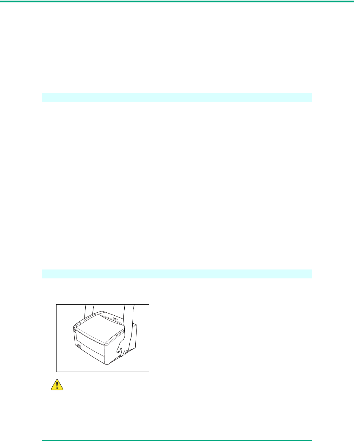
Moving the Scanner
• When moving the scanner, always hold it with both hands to avoid dropping it. The scanner weighs
approximately 14.1 lb (6.4 kg).
CAUTION
Make sure to disconnect the interface cable and power cord when moving the scanner. If the
scanner is transported with these items plugged in, the plugs and connectors may be
damaged.

Chapter 1 Before Using the Scanner
1-3
Handling
WARNING
Note the following precautions whenever using the scanner. Failure to do so may result in a
fire or electric shock.
■Never use alcohol, benzene, paint thinner, aerosol sprays, or any other highly flammable
substance near the scanner.
■Do not cut, damage, or modify the power cord. Do not place heavy objects on the power
cord, and do not pull or excessively bend the power cord.
■Never connect the power cord when your hands are wet.
■Do not connect the scanner to a multi plug power strip.
■Do not knot or coil the power cord as this may result in a fire or electric shock. When
connecting the power cord, make sure that the power plug is securely and completely
inserted into the power outlet.
■Do not use power cords other than the power cord provided with this scanner.
■Never try to take the scanner apart or modify it in any way, as this is dangerous and may
lead to a fire or electric shock.
■When cleaning the scanner, turn the power switch OFF and disconnect the power cord
from the power supply.
■Clean the scanner using a slightly dampened cloth which has been well wrung out. Never
use alcohol, benzene, paint thinner, or any other flammable substances.
■If the scanner makes strange noises, or gives off smoke, heat, or strange odors, or the
scanner does not function or other abnormalities occur when you use the machine,
immediately turn the power switch OFF, and disconnect the power plug from the power
outlet. Then, contact your local authorized Canon dealer or the service representative for
further information.
■Do not drop the scanner, or subject it to impact or strong shock. Should the scanner ever
become damaged, immediately turn the power switch OFF, and disconnect the power plug
from the power outlet. Then, contact your local authorized Canon dealer or service
representative to have the unit serviced.
■Before moving the scanner, be sure to turn the power switch OFF, and disconnect the
power plug from the power outlet.
CAUTION
■Do not install the scanner on a surface that is unstable or tilted, or in an area subject to
excessive vibrations, as this may cause the scanner to fall, resulting in personal injury or
damage to the scanner.
■Do not block ventilation openings. Doing so could case the scanner to overheat, creating
a risk of fire.
■Never place small metal objects such as staples, paper clips, or jewelry on the scanner.
These items may fall into the scanner, and cause a fire or electric shock. Should such
objects ever fall inside the scanner, immediately turn the power switch OFF, and
disconnect the power plug from the power outlet. Then, contact your local authorized
Canon dealer or service representative to have the unit serviced.
■Do not install the scanner in a humid or dusty location. Doing so might cause a fire or
electric shock.

Chapter 1 Before Using the Scanner
1-4
■Do not place objects on top of the scanner. Such objects may tip or fall over, resulting in
personal injury.
■When unplugging the power cord, grasp it firmly by its plug. Do not pull directly on the
power cord, as this may damage or expose the cord’s internal wiring, resulting in a fire or
electric shock.
■Leave sufficient space around the power plug so that it can be unplugged easily. If objects
are placed around the power plug, you will be unable to unplug it in an emergency.
■Do not allow water or flammable substances (alcohol, paint thinner, benzene, etc.) to spill
into the scanner, as this may result in a fire or electric shock.
■Turn OFF the power switch for safety when not using the scanner for a long period of time,
such as overnight. Also, turn OFF the power switch, and disconnect the power cord from
the power outlet for safety when the machine will not be used for an extended period of
time, such as during consecutive holidays.
■Do not wear loose clothing or jewelry that may get caught in the scanner while you are
using it. This may result in personal injury. Be extra careful of neckties and long hair. If
anything becomes caught in the scanner, immediately disconnect the power cord to stop
the scanner.
■Be careful when placing paper in the scanner and when removing jammed paper. It is
possible to cut your hand on the edge of a sheet of paper.
Disposal
When disposing of this scanner, be sure to follow all local ordinances and laws or consult with the
retailer who sold you the scanner.

Chapter 1 Before Using the Scanner
1-5
1-2 Features of the DR-4010C Document
Scanner
The main features of the DR-4010C document scanner are described below.
• Fast Document Feeding
The scanner can scan a maximum of 42 documents per minute in a range of sizes from business
cards to LTR/A4 size. (Scanning conditions: Black and white, LTR/A4 size portrait, 200 dpi.)
Scanning speed is the same for both color and grayscale scanning.
• USB/SCSI Interface Supported
The USB interface that was provided as standard on your computer and SCSI extension cards
are supported. (See “2-2 Installation Requirements,” on p. 2-2.)
• Color/Grayscale Support
Documents can be scanned in 24-bit color or 256-level grayscale.
• Supports a Variety of Scanning Modes
The scanner supports the following scanning modes, depending on the document type:
- Single-sided/double-sided mode
- Single sheet/dual feeding path
• U-Turn Path
Documents are fed and ejected from the front of the scanner. (See “3-2 Document Feed and
Eject Tray,” on p. 3-3.)
• Straight Path
Documents are ejected to the back of the scanner. Note that the ejected documents are stacked
in the reverse order from which they were fed. (See “3-2 Document Feed and Eject Tray,” on p. 3-
3.)
• Paper Size Detection
The scanner automatically detects the size of a scanned document and eliminates any
unnecessary space around the edges of the image when storing the image, even when storing a
document of irregular size.
• Double Feed Detection
The scanner stops feeding documents after detecting more than one document being fed at the
same time. (See “Double Feed Detection Function,” on p. 3-30.)
• Deskew
The scanner straightens images after detecting that a document was placed askew.
• Card Scan
You can scan business or ID cards. Note that embossed credit cards or similar items cannot be
scanned. (See “3-1 Documents,” on p. 3-1.)
• Auto Color Detection
The scanner detects whether the scanned document is in color or black-and-white, and saves the
image accordingly.
• Text Orientation Recognition
This mode identifies the orientation of characters in a document, and rotates the image so the
orientation of the scanned characters is straight.

Chapter 1 Before Using the Scanner
1-6
• Text Enhancement Mode
This mode enables you to scan documents with dark backgrounds or documents with faint text
written in pencil clearly.
Note
This mode may not function effectively, depending on the document type.
• Dropout Color
The scanner is equipped with a Dropout Color function that enables you to specify a color for the
scanner to omit from the scanned image.
• Color Enhancement
The scanner is equipped with a Color Enhancement function that enables you to specify a color
for the scanner to enhance on the scanned image.
• Skip Blank Page Function
The scanner is equipped with a Skip Blank Page function that enables you to scan a document
without storing images of blank pages, regardless of whether each page of the document is two-
sided or one-sided.
• Prescan Function
The scanner is equipped with a Prescan function that allows you to adjust the contrast and
brightness of a prescanned image and then send the adjusted image to the application software,
without needing to scan the document again.
• Remove Binder Holes
This mode erases the black spots that appear on scanned images from binding holes on the
original document.
• MultiStream Function
The scanner supports MultiStream, which, according to the application, can create two images
with different scanning conditions from one path scan.
However, this function can only be used if the software supports MultiStream. (See “MultiStream
Function,” on p. 3-34.)
• Long Document Compatibility
You can scan documents up to 39.2 inches (1000 mm) long by setting the Long Document mode.
(See “Long Document Mode,” on p. 3-30.)
• Compatible with Carbonless Duplicating Paper
The scanner is able to scan carbonless duplicating paper.
• Energy Saving Mode
This scanner is compatible with the International Energy Star Program, and is designed to save
power by using the energy saving feature except when scanning is being performed.
Note
Some functions may not be available depending on the software you are using.
Chapter 1 Before Using the Scanner
1-7
1-3 Names and Functions of Parts
This section describes the name and function of each part. Make sure to read this section and
familiarize yourself with the parts of the scanner before using the scanner.
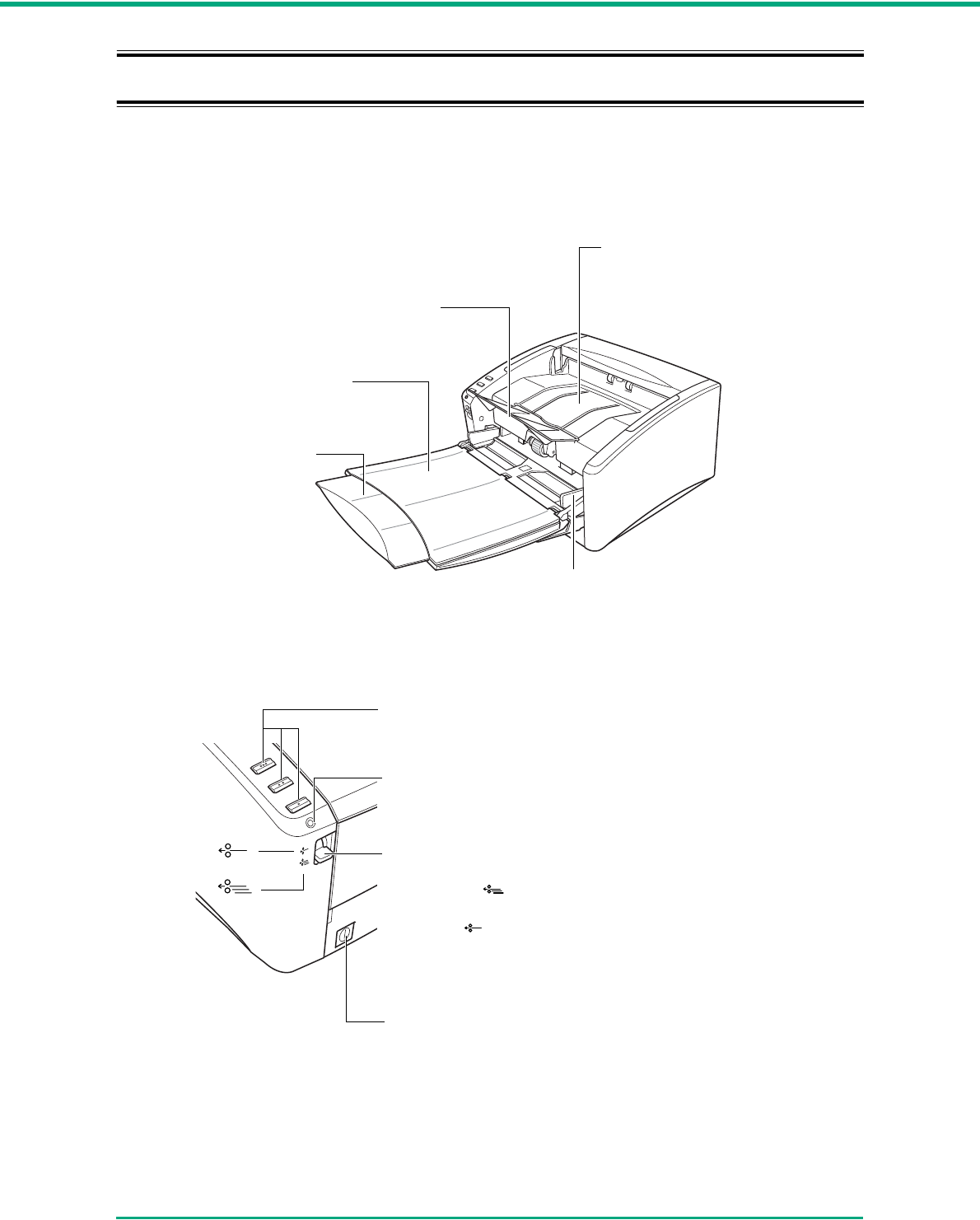
■Front View (Feed Tray Open)
■Controls
Document Feed
Tray Extension
Pull this tray out if
the document hangs
over the edge of the
main tray.
(See p. 3-3.)
Document Guides
Adjust these guides to fit
the width of the document.
(See p. 3-6.)
Document Feed Tray
Place the document to be
scanned here. (See p. 3-3.)
Document Eject Tray Extension
Open if the document extends beyond the edge
of the eject tray. (See p. 3-3.)
Document Eject
Tray
Scanned documents
are ejected here. (See
p. 3-3.)
Feed Selection Lever
Use this lever to change the way documents are fed.
Push it down ( ) to feed documents continuously
(page separation mode.) (See p. 3-5.)
Push it up ( ) to feed documents one at a time or to
feed documents that are fastened together, such as
invoices, without separating them (bypass mode.) (See
p. 3-7.)
Power Indicator
This indicator lights when the scanner is turned ON.
(See p. 2-14.)
Power Switch
This switch is used to turn the scanner ON. (See p. 2-13.)
Job Buttons
These buttons can perform user-specified functions
assigned with the Job Registration Tool. (See p. 3-9.)
Chapter 1 Before Using the Scanner
1-8
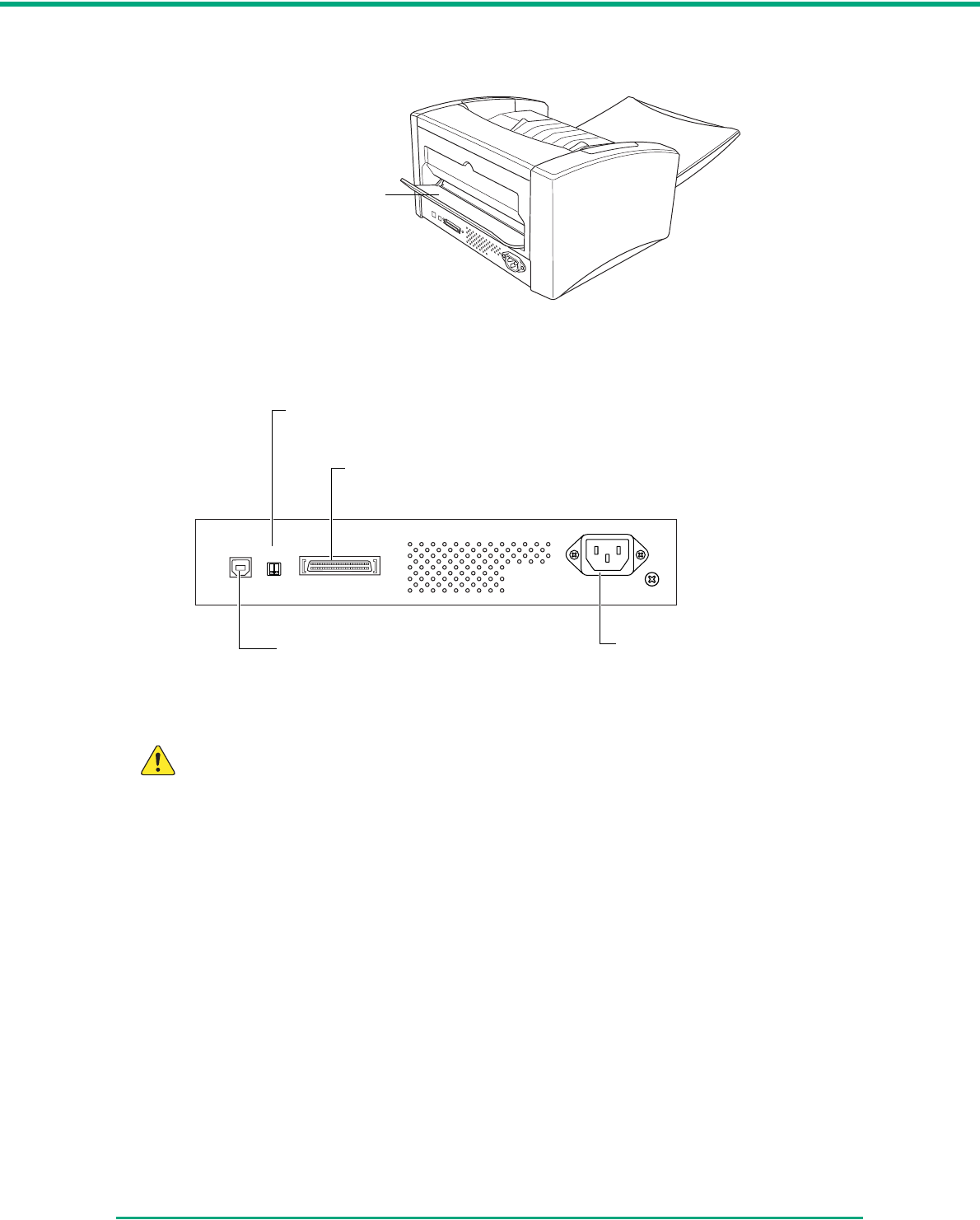
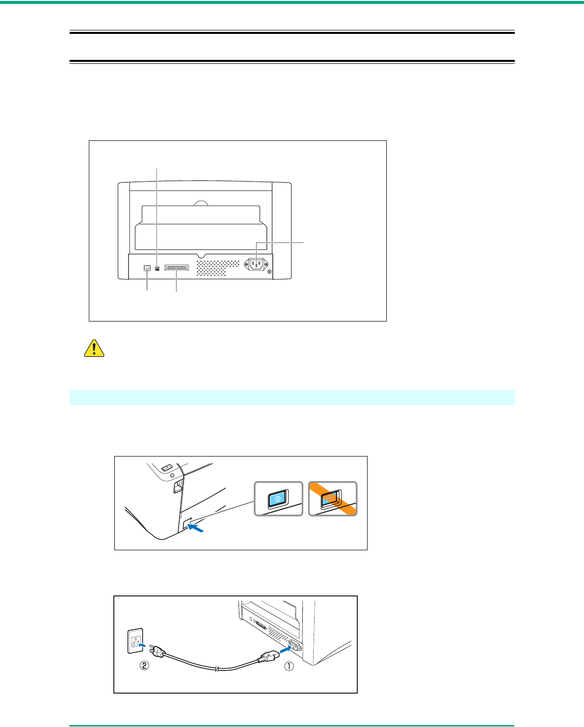
■Back View
■Interfaces (See “2-4 Connecting the Scanner to the Computer,” on p. 2-
11.)
CAUTION
• Do not block the ventilation openings. Doing so could cause the scanner to overheat,
creating a risk of fire.
• Do not connect both a USB cable and a SCSI cable at the same time. Doing so may
cause a malfunction.
Document Eject Tray 2
Open this tray to use the
scanner in a straight path
configuration. (See p. 3-3.)
1
ON
2
USB Connector
Connect the provided USB
cable or a USB cable that
supports Hi-Speed USB 2.0.
DIP Switches
Set the SCSI ID.
SCSI Connector
Connect to a 50-pin half-pitch (pin type) SCSI cable.
(Ventilation Holes)
Power Connector
2-1
Chapter 2
Setup
2-1 Setup Procedure
In order to prepare the scanner for use, read and follow the instructions in each section below.
Installation Requirements
Installing the Software
Connecting the Scanner to the Computer
Turning the Power ON
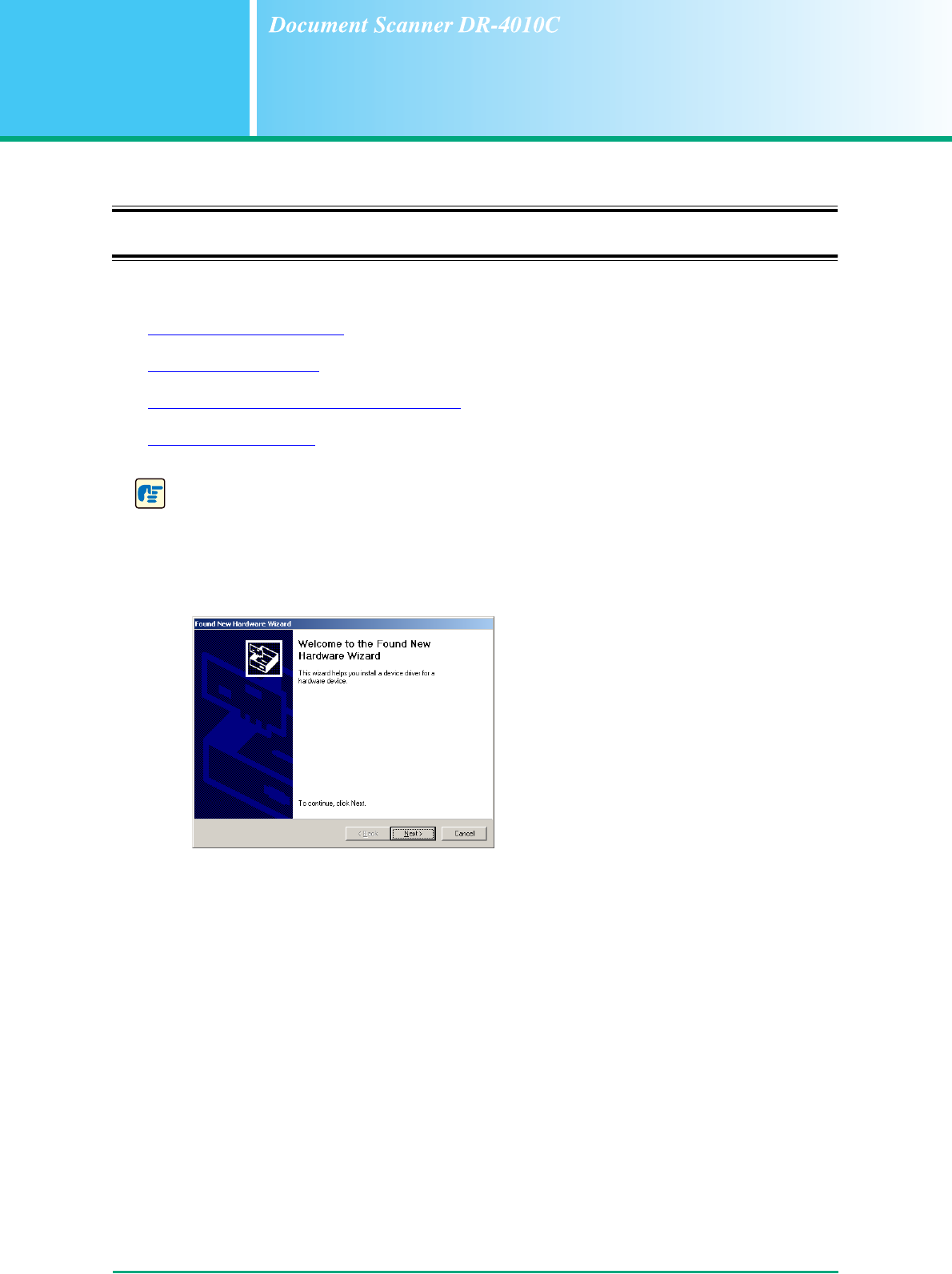
IMPORTANT
• Be sure to install the software before connecting the scanner to the computer.
• If you connect the scanner to the computer before installing the software, a wizard screen
such as shown below will appear when you turn power to the scanner ON. In such a case,
click the [Cancel] button to close the wizard screen and then turn power to the scanner OFF.
Wizard Screen (Windows 2000)

Chapter 2 Setup
2-2
2-2 Installation Requirements
To use the DR-4010C scanner, your computer must satisfy the following system requirements.
• One of the following operating systems:
- Microsoft Windows 2000 Professional SP4 or later
- Microsoft Windows XP Professional SP2 or later
- Microsoft Windows XP Home Edition SP2 or later
- Microsoft Windows XP Professional x64 Edition
• A computer that meets the following specifications:
- CPU: Pentium 4 (3.2 GHz or faster)
- Memory: 1 GB or more
- Hard disk: 1 GB or more available space
- Interface: USB port present as standard equipment on the computer (Hi-Speed USB 2.0)
or SCSI expansion card
- Monitor: Resolution of 1024 × 768 (XGA) or better recommended.
• When using a SCSI expansion card, select one of the following recommended models.
SCSI cards made by Adaptec (for PCI bus)
- AHA-2930U
- AHA-2940AU
- ASC-19160
- ASC-29160N
SCSI card made by Adaptec (for Card bus)
- APA-1480
• An ISIS-compatible application or a TWAIN-compatible application that is compatible with the
above operating systems.
IMPORTANT
• If you do not know the requirements for your computer system, contact the store where you
purchased the computer or the manufacturer of the computer for more information.
• Do not connect both a USB interface and a SCSI card at the same time.
• Be aware of the following information when using the USB interface that was provided as
standard with your computer.
- The USB interface should be a Hi-Speed USB 2.0 interface.
- Scanning speeds are lower if your computer’s standard USB interface is USB Full-Speed
(equal to USB 1.1.) In this case, using a SCSI expansion card is recommended.
- Use the latest USB 2.0 driver made available by Microsoft. For details, consult your local
authorized Canon dealer.
- Normal operation is not guaranteed with all USB interfaces, even if present as standard
equipment on the computer. For details, consult your local authorized Canon dealer.
- The USB cable you are using should be the one originally included with the scanner or a
Hi-Speed USB 2.0 compatible cable.
• Be aware of the following information when using a SCSI card.
- Make sure to follow the procedure in the manual for the SCSI card and the computer that
you are using when installing a SCSI card in your computer.
- The overall length of the SCSI cable you can use is determined by the SCSI standards.
Refer to the manual for the SCSI card you are using for more information.

Chapter 2 Setup
2-3
• If the CPU, memory, interface card, and other specifications do not satisfy the installation
requirements, the scanning speed may be greatly reduced and transmission may take a
long time.
• Even if the computer satisfies the recommended specifications, the scanning speed may
vary, depending on the scan settings.
• The ISIS/TWAIN Drivers provided with the scanner do not necessarily operate on all ISIS-
or TWAIN-compatible applications. For details, contact your application software retailer.
Chapter 2 Setup
2-4
2-3 Installing the Software
This section describes how to install the required software.
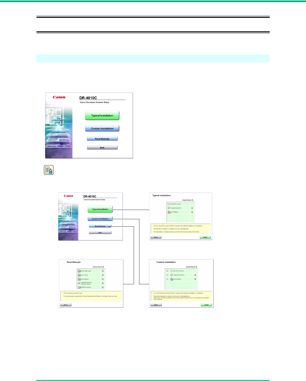
Setup Disc
When you insert the Setup disc supplied with the scanner into the CD-ROM drive of your computer,
the menu shown below should appear. If this menu does not appear, use Explorer to access the CD-
ROM drive and execute the file “SETUP.EXE.”
Note
The Setup disc of the DR-4010C is configured as follows.
Menu screen Typical Installation
Read Manuals Custom Installation
All of the indicated software is installed.
Only the software with a
selected check box is installed.
The User Manual and CapturePerfect
3.0 Operation Guide electronic manuals
for the scanner are installed on the
computer with the rest of the software.
Chapter 2 Setup
2-5
Software Installation
Install the software before connecting the scanner to the computer.
1Log onto Windows with an account that has Administrator privileges.
IMPORTANT
• Be sure to log on as an Administrator.
• Close all other applications before installing the software.
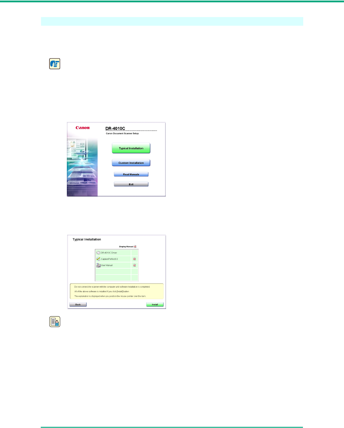
2Insert the DR-4010C Setup disc into the PC’s CD-ROM drive.
The menu screen appears automatically when you insert the CD-ROM into the CD-ROM
drive. If the setup wizard does not start up, execute setup.exe in the CD-ROM.
3Click [Typical Installation].
The [Typical Installation] screen appears.
Note
• When you select [Typical Installation], all of the displayed software and the User Manual will
be installed automatically. If you want to reinstall only specific software that you have
previously uninstalled, select [Custom Installation] and specify the software.
• The DR-4010C driver installation comprises the Scanner Driver and Job Tool installation.
Menu Screen
Chapter 2 Setup
2-6
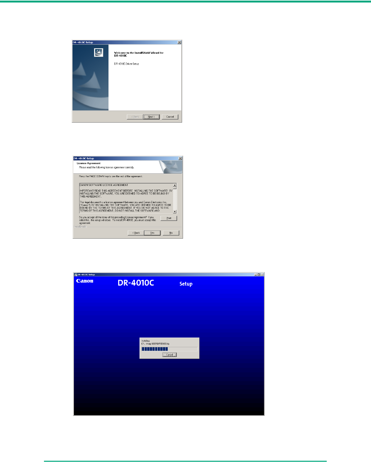
4Click [Install].
Installation of the DR-4010C driver begins.
5Click [Next].
The software license agreement appears.
6Read the license agreement and click [Yes] to accept it.
The DR-4010C driver is installed.
Chapter 2 Setup
2-7
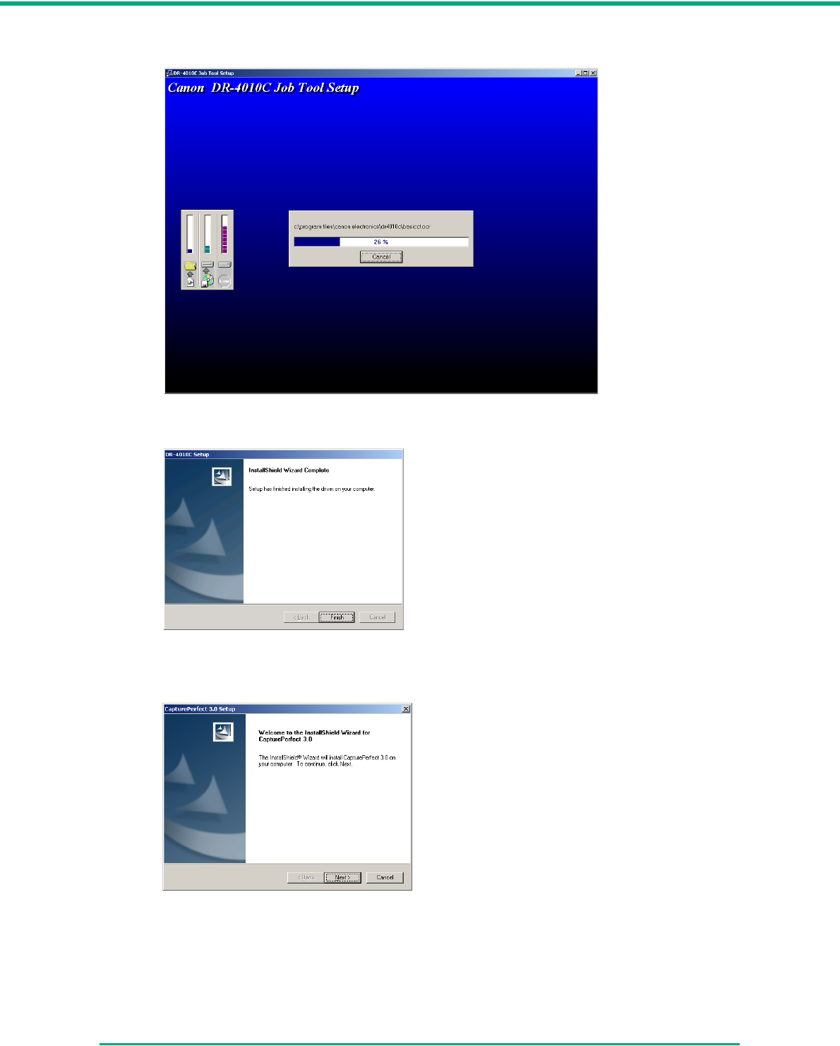
Next, the job tool software is installed.
7The DR-4010C driver installation is complete.
8Click [Finish].
Installation of CapturePerfect 3.0 starts.
Chapter 2 Setup
2-8
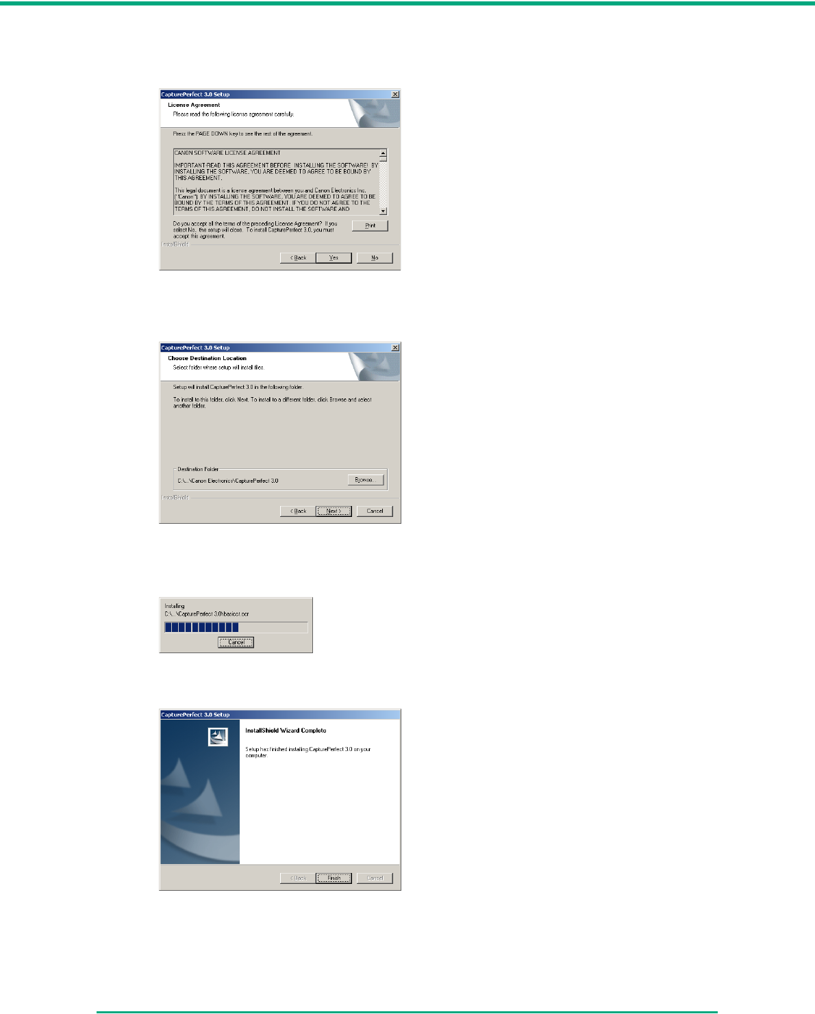
9Click [Next].
The software license agreement appears.
10 Read the license agreement and click [Yes] to accept it.
The installation location screen appears.
11 Click [Next].
CapturePerfect is installed.
12 The CapturePerfect installation is complete.
Chapter 2 Setup
2-9
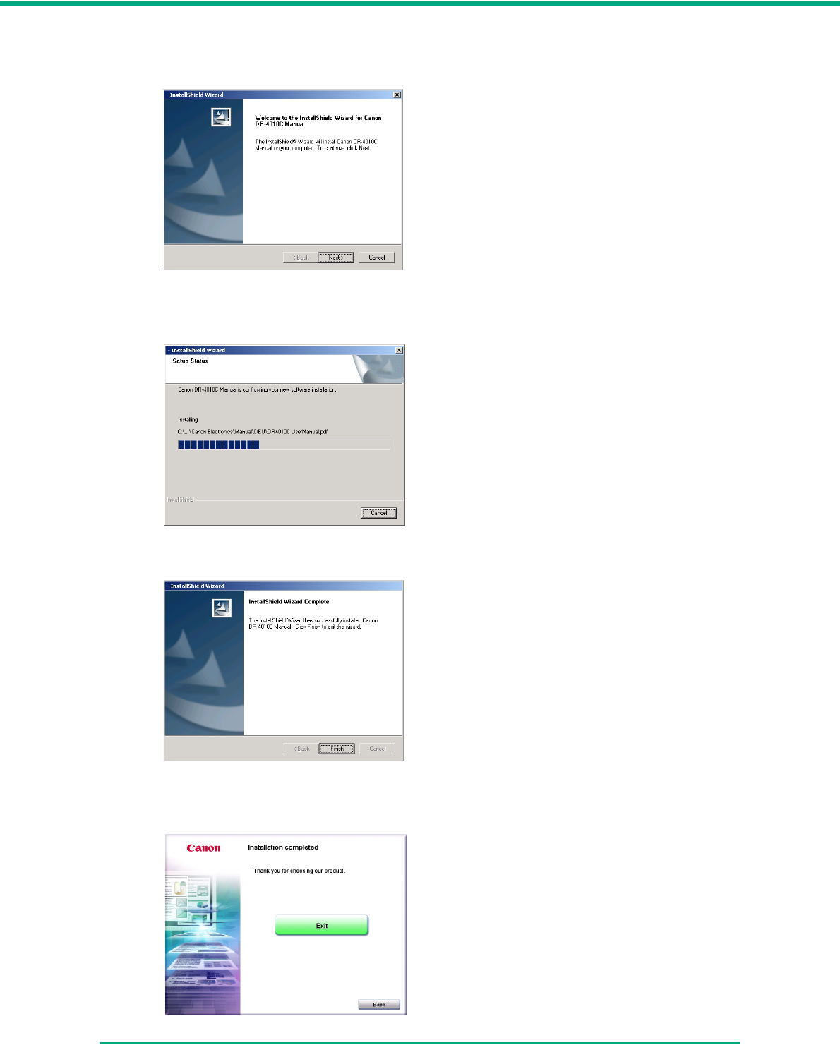
13 Click [Finish].
Installation of the User Manual starts.
14 Click [Next].
The User Manual is installed.
15 The User Manual installation is complete.
16 Click [Finish].
The installation completion screen appears.

Chapter 2 Setup
2-11
2-4 Connecting the Scanner to the Computer
There are two methods for connecting the DR-4010C scanner to a computer: USB connection,
which makes use of a standard USB port on the computer, and SCSI connection, which makes use
of a SCSI card installed in an expansion slot of the computer. Select the method that is suitable for
your computer environment.
CAUTION
Do not connect a USB cable and SCSI cable at the same time.
Using a USB Connection
1Verify that the power switch of the scanner is OFF.
If the power switch is in the ON position, push the switch to set it to OFF.
2Plug the supplied power cord into the power connector on the back of the scanner. a
SCSI ID DIP Switches
USB Connector SCSI Connector
(half-pitch 50-pin, pin-type)
Power Connector
Power switch
OFF position ON position
Chapter 2 Setup
2-12
3Connect the power cord into an AC outlet. b
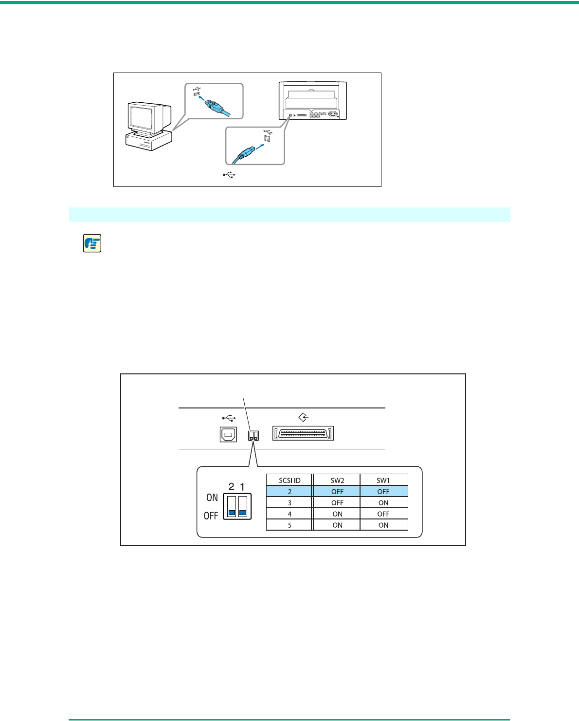
4Use the supplied USB cable to connect the scanner to the computer.
Using a SCSI Connection
IMPORTANT
• Make sure that the computer is turned OFF before connecting the SCSI cable. If the cable is
connected while the computer is on, the scanner may not be properly recognized by the
computer.
• A SCSI cable is not supplied with the scanner. Purchase a cable that is suitable for the
scanner and for the SCSI connector on the computer.
• The SCSI ID of the scanner is set to “SCSI ID = 2” by default. When using a daisy-chain
configuration with other SCSI devices, set the DIP switches so that there is no duplication of
SCSI ID numbers in the system.
• The DR-4010C scanner incorporates a SCSI terminator which is permanently set to ON.
When using a daisy-chain configuration with other SCSI devices, make sure that the DR-
4010C is connected as the last device in the chain. Set the terminators of all other devices
to OFF.
Ty p e A
Ty p e B
symbol on plug should face down
DIP switches
Factory default (SCSI ID = 2)
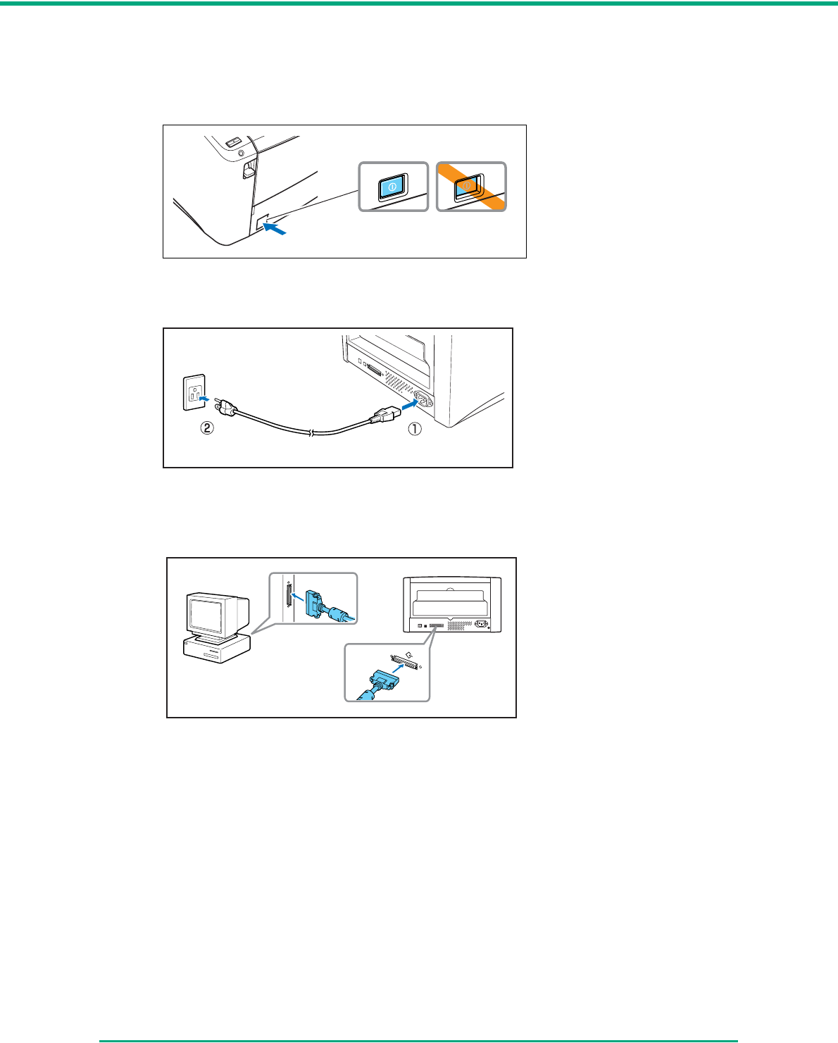
Chapter 2 Setup
2-13
1Shut down Windows and turn the computer OFF.
2Verify that the power switch of the scanner is OFF.
If the power switch is in the ON position, push the switch to set it to OFF.
3Plug the supplied power cord into the power connector on the rear of the unit. a
4Connect the power cord into an AC outlet. b
5Use the SCSI cable to connect the scanner to the computer.
Power switch
OFF position ON position
Chapter 2 Setup
2-14
2-5 Turning the Power ON
When you turn the computer and the scanner ON, the Plug and Play function of Windows
recognizes the scanner and automatically installs the required device driver.
IMPORTANT
• When connecting the scanner to the computer using a SCSI cable, be sure to turn power to
the scanner ON first, and then turn power to the computer ON. If you turn power to the
computer ON first, the scanner may not be properly recognized by the computer.
• If you turn the power OFF, wait at least 10 seconds before turning it ON again.
• If you will not be using the scanner for an extended period, you should disconnect the power
cord from the AC outlet for safety.
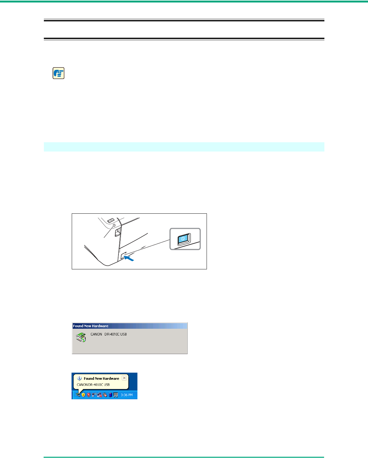
Scanner Recognition
The scanner will be recognized the first time it is connected to the computer.
1Make sure that the scanner and computer are connected properly.
2Press the power switch to turn the scanner ON.
The power indicator lights green.
3Turn the computer ON.
4Log onto Windows with an account that has Administrator privileges.
5Windows recognizes the DR-4010C automatically, and installation of the device driver begins.
Windows 2000
Windows XP
Power switch
Power indicator
ON
Chapter 2 Setup
2-15
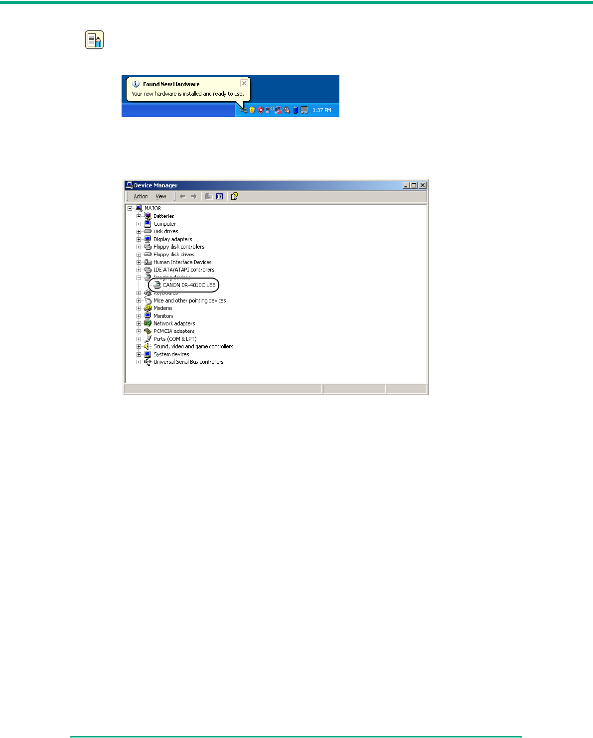
Note
• In Windows XP, a message appears when installation is complete.
• In Windows 2000, no message appears when installation is complete.
• The DR-4010C is installed in Device Manager under [Imaging Devices] as [CANON DR-
4010C USB] or [CANON DR-4010C SCSI].
3-1
Chapter 3
Basic Operation
3-1 Documents
The scanner can scan documents ranging in size from business cards and checks to A4 size
documents. It can also scan long documents up to 39.2” (1000 mm).
The document sizes that this scanner can scan are shown below.
(*1) The DR-4010C offers two document eject configurations: U-turn path (the document is ejected
to the document eject tray at the front of the scanner) and straight path (the document is ejected
to the back of the scanner.) (See “3-2 Document Tray and Eject Tray,” on p. 3-3.)
(*2) You can scan documents up to 39.2” (1000 mm) long by setting the scanner to the Long
Document mode. (See “Long Document Mode,” on p. 3-30.)
(*3) The paper weights that can be used with the scanner vary depending on the document feed
method (page separation mode or bypass mode.) (See “3-3 Placing Documents,” on p. 3-5.)
Eject Direction (*1) U-Turn Path Straight Path
Width 2.08" to 8.62"
(53 mm to 219 mm)
2.08" to 8.62"
(53 mm to 219 mm)
Length (*2) 2.75" to 14"
(70 mm to 356 mm)
2.75" to 14"
(70 mm to 356 mm)
Weight (*3)
Feeding documents
are separated
(Page separation
mode)
Feeding documents
are not separated
(Bypass mode)
14 to 32 lb bond
(52 to 128 g/m2)
0.0024" to 0.0059"
(0.06 mm to 0.15 mm)
11 to 40 lb bond
(42 to 157 g/m2)
0.0020" to 0.0079"
(0.05 mm to 0.20 mm)
11 to 32 lb bond
(42 to 128 g/m2)
0.0020" to 0.0059"
(0.05 mm to 0.15 mm)
11 to 144 lb bond
(42 to 546 g/m2)
0.0020" to 0.0026"
(0.05 mm to 0.66 mm)
Business Cards
ID Cards
Cannot be scanned Can be scanned
Size: 2.12" × 3.37"
(53.9 mm × 85.5 mm)
Thickness:
0.03" ± 0.003"
(0.76 ± 0.08 mm)
without embossing
U-turn Path
Document Eject Tray 2
Straight Path
Chapter 3 Basic Operation
3-2
IMPORTANT
A document must meet the following criteria to be scannable:
• When scanning a multiple page document, pages of the same size, thickness, and weight
must be grouped together. Scanning different sizes and types of paper together can cause
the scanner to jam.
• Scanning documents before the ink is dry can cause problems with the scanner. Always
make sure that the ink on a document is dry before scanning it.
• Scanning documents that are written in pencil or similar material have a tendency to make
the rollers and scanning glass dirty, which can lead to smudges in the scanned image and
transfer the dirt to subsequent documents. Always clean the internal parts of the scanner
after scanning such documents.
(See “Cleaning the Sensor Glass and the Rollers,” on p. 4-2.)
• When scanning a two-sided document that is printed on thin paper, the image on the
opposite side of each page may show through. In this case, adjust the scanning intensity in
the application software before scanning the document.
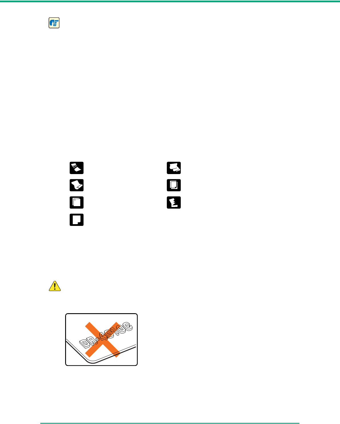
• Scanning the following types of documents can cause a paper jam or malfunction. To scan
such a document, make a photocopy of the document and then scan the photocopy.
• When you scan a batch of NCR (No Carbon Required) documents, make sure that they are
not stuck together.
• Note that glossy paper or business cards may not be scanned correctly, or functions such
as paper size detection and deskew may not function properly when scanning these types
of documets, due to reflected light.
• When scanning business cards, make sure to select the bypass mode and straight path.
CAUTION
The results of scanning embossed cards are not guaranteed. Scanning embossed
cards is not recommended, as they may scratch the sensor glass.
Wrinkled or creased
documents
Extremely thin, translucent
paper
Curled document Carbon paper
Documents with paper clips or
staples
Torn documents
Coated paper
Embossed Card
Chapter 3 Basic Operation
3-3
3-2 Document Tray and Eject Tray
Prepare the document feed tray and document eject tray according to the paper size and feed/eject
method.
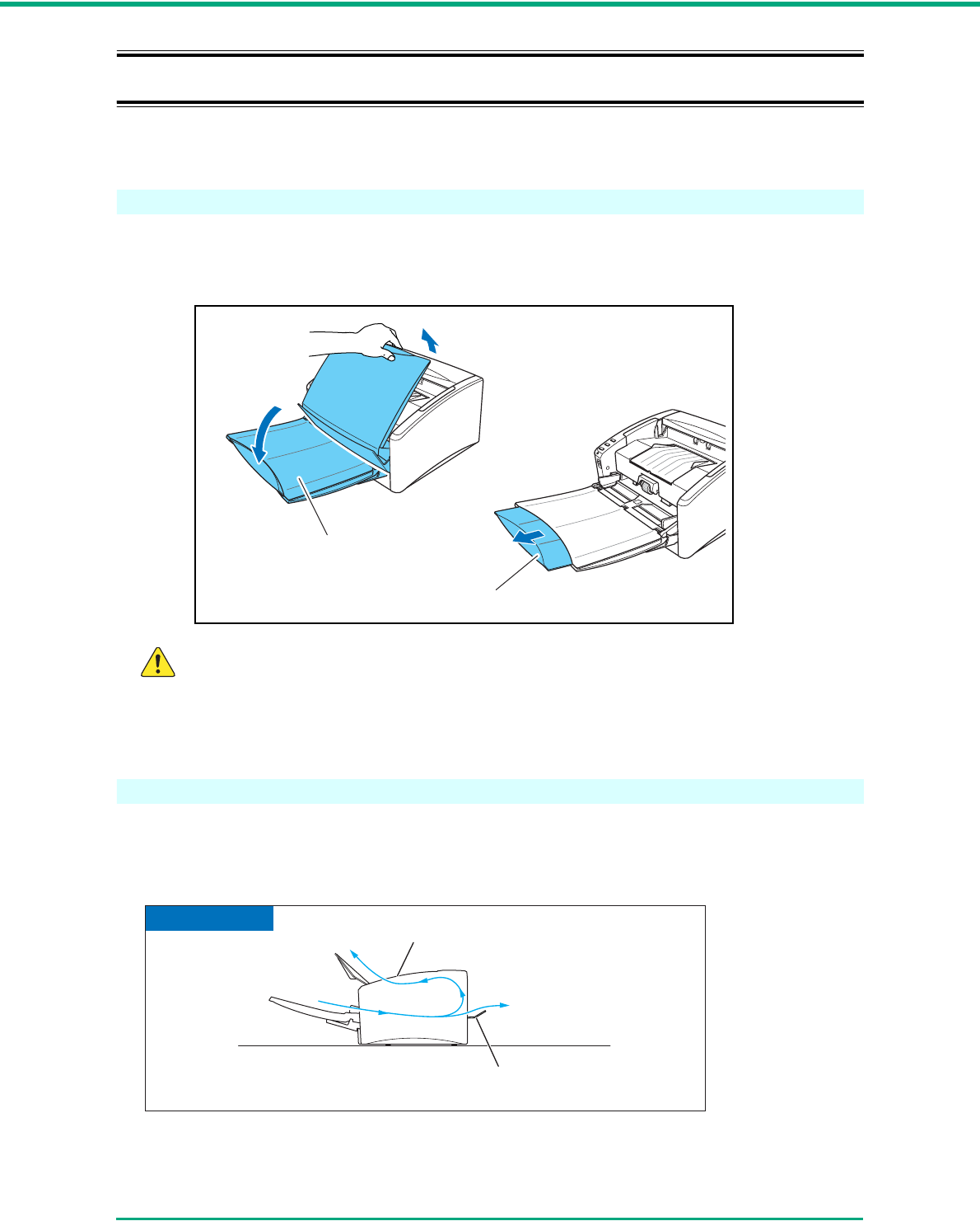
Preparing the Document Feed Tray
1Grasp the middle of the document feed tray and slowly open it toward you. If the documents
slide off the tray, pull out the document feed tray extension.
CAUTION
Do not place anything other than documents on the document feed tray. Doing so may
damage the scanner, reduce scanning quality, or cause the tray to fall off, resulting in
personal injury or damage to the scanner.
Preparing the Document Eject Tray
The scanner has two eject methods: documents can be ejected to the front of the scanner in a U-
turn path, or to the back of the scanner in a straight path. You can switch between these methods by
opening or closing the document eject tray 2. Select an eject method according to your needs.
Document Feed Tray
Document Feed Tray Extension
U-turn Path
Document Eject Tray 2
Straight Path
Document Eject tray
Document Flow

Chapter 3 Basic Operation
3-4
Note
• The U-turn path is used to scan documents on paper of normal weight. Scanned
documents are ejected to the document eject tray.
• The straight path is used to scan documents on thin paper, thick paper and business cards
that cannot be scanned through the U-turn path. Scanned documents are ejected to the
back of the scanner.
• The U-turn path cannot be used if the document eject tray 2 is open.
• When using the straight path, the pages are stacked in the reverse order from which they
were fed.
IMPORTANT
• Be sure there is enough space for documents that are ejected at the back of the scanner
when using the straight path. If there is not enough space for the ejected pages, the
documents may be damaged or a paper jam may occur.
• Open or close the document eject tray 2 before starting to scan documents. Opening or
closing the document eject tray 2 while scanning may cause a paper jam.
• When using the U-turn path, make sure to open the eject tray guide. If the guide is not
opened, documents may fall off the tray and cause a paper jam.
Straight Path
U-turn Path
Open document eject tray 2.
Close document eject tray 2, and open the document eject
tray extension.
Document Eject Tray 2
Document Eject Tray Extension
Document Eject Tray 2
Chapter 3 Basic Operation
3-5
3-3 Placing Documents
There are two methods for feeding documents, the Page Separation mode and Bypass mode.
Feeding pages continuously from a stack of documents placed in the feed tray is called the Page
Separation mode. Feeding documents one sheet at a time or feeding documents consisting of
multiple pages that are attached, is called the bypass mode. The document feed method can be
changed by moving the feed selection lever.
IMPORTANT
• Always smooth out any folds or curls in your documents before placing them into the feeder.
If the leading edge of a document is curled, it may cause a paper jam.
• When continuously scanning documents on thin paper in the page separation mode, the
pages may become wrinkled or folded and cause a paper jam. If this happens, scan the
document in the bypass mode.
CAUTION
■Before you place a document, check to make sure it does not contain paper clips,
staples, or other small metal objects. These items may cause a fire or electrical
shock, damage the document, or cause a paper jam or scanner malfunction.
■Do not wear loose clothing or jewelry that may get caught in the scanner while you
are using it. This may result in personal injury. Be extra careful of neckties and long
hair. If anything gets caught in the scanner, immediately turn OFF the power switch,
and disconnect the power cord from the power outlet to stop scanning.
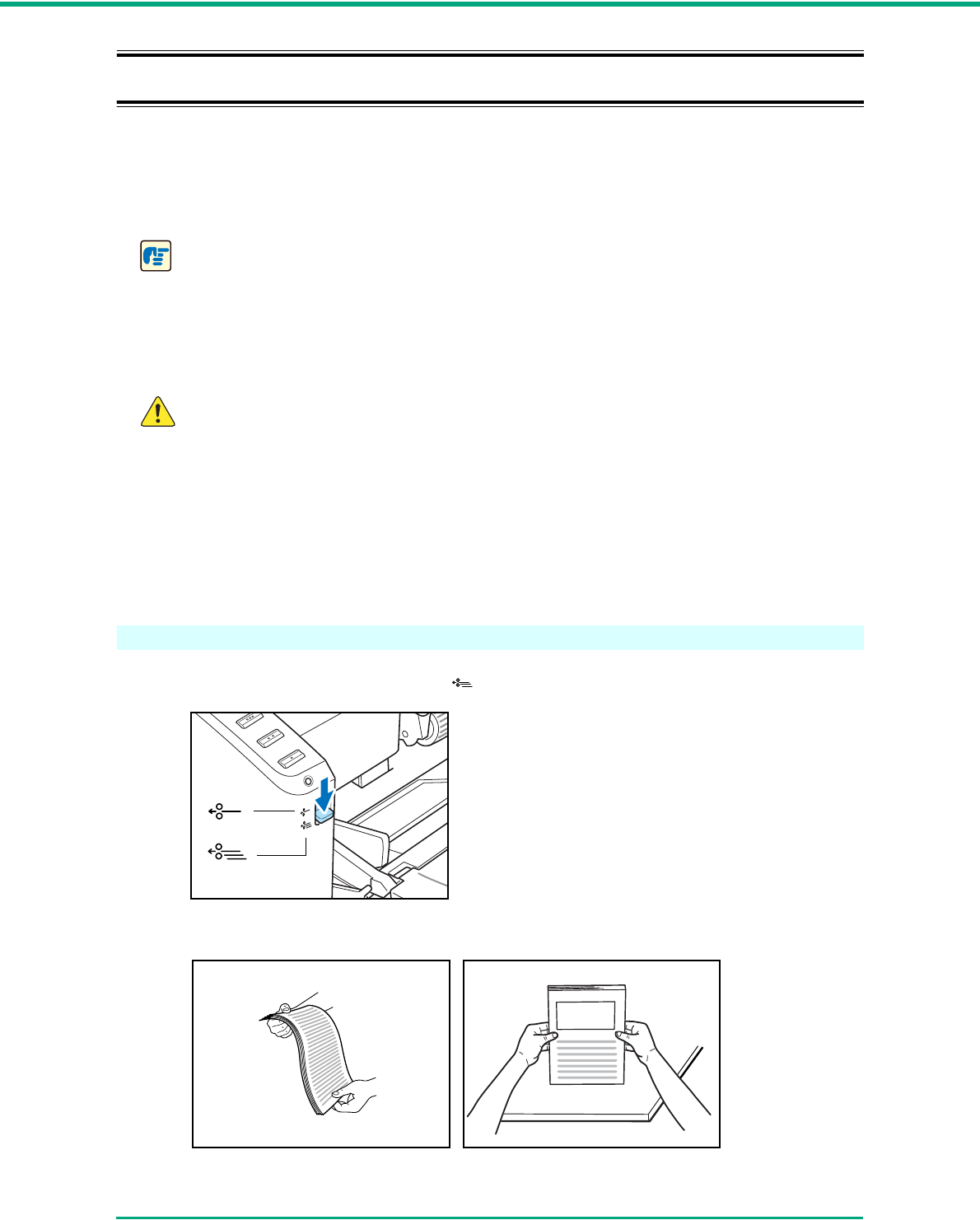
Feeding in the Page Separation Mode
1Push the feed selection lever down ( .)
2Fan the pages of the document to be scanned and align their edges.
Chapter 3 Basic Operation
3-6
CAUTION
■Do not place the documents on top of the scanner to align them. Doing so may
cause a malfunction.
■When placing documents into the feed tray, take care not to cut your hands on the
edges of the paper.
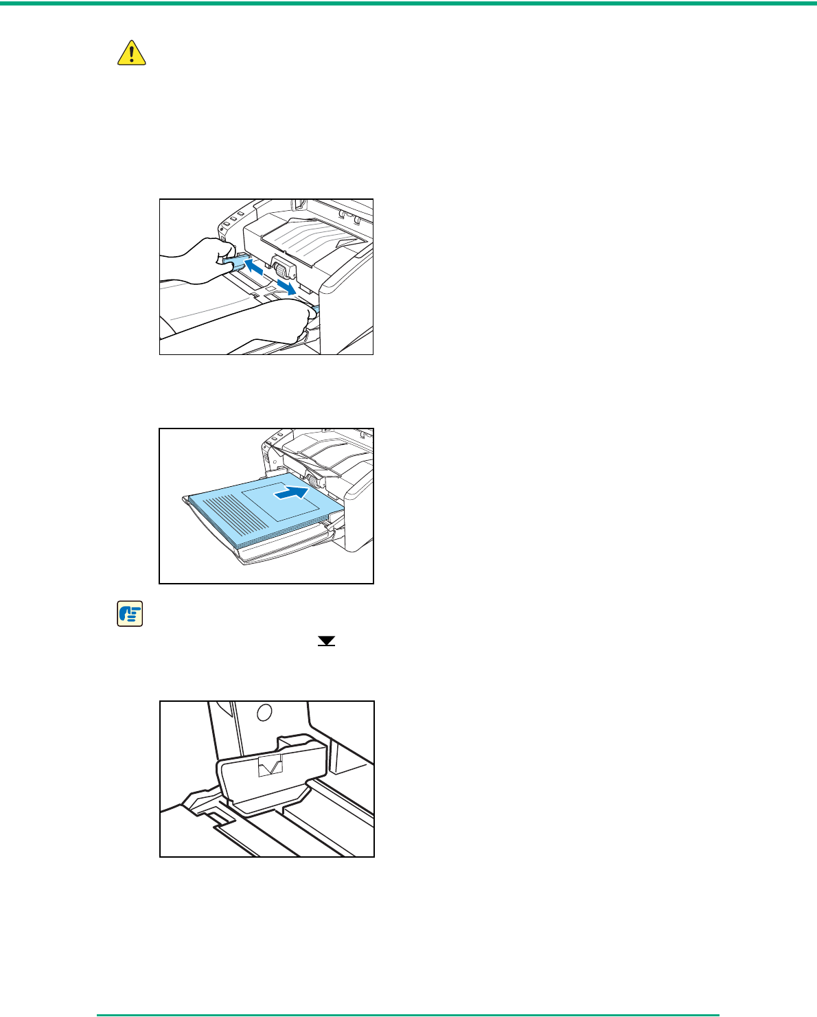
3Adjust the document guides so that they are wider than the document to be scanned.
4Place the document face up into the feed tray, so that the leading edge of the paper touches
the document stoppers.
IMPORTANT
There is a load limit mark ( ) on the document guides. Do not stack documents higher than
this mark (approximately 100 sheets of 20 lb bond (80 g/m2) paper.) Doing so may cause a
paper jam.
Chapter 3 Basic Operation
3-7
5Adjust the document guides to fit the width of the document.
Note
Before scanning, make sure that the document is not curled or creased, and that it is placed in
the feed tray correctly. Scanning an improperly placed, curled, or creased document may
damage the document or cause a paper jam.
6Start scanning.
IMPORTANT
• If feeding stops due to a system error or paper jam while the scanner is scanning, resolve
the problem, make sure that the scanned image of the last page that was successfully fed
has been stored, and then resume scanning the remaining document pages.
• Note that documents that are printed on thin paper may fall out of the document eject tray.
• After you finish scanning, close the document feed tray and the document eject tray
extension to prevent damage to the scanner while it is not being used.
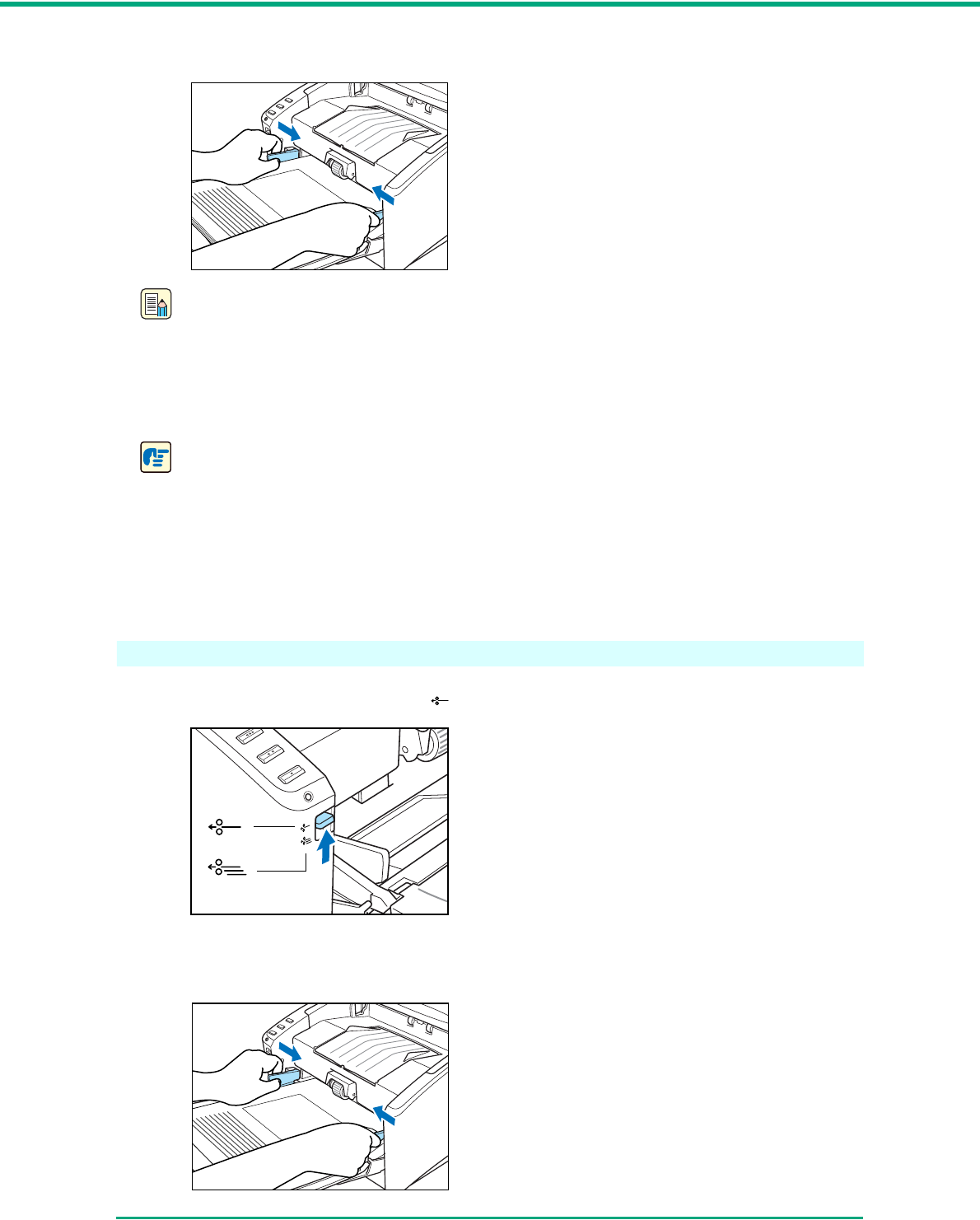
Feeding in the Bypass Mode
1Push the feed selection lever up ( .)
2Place the document into the document feed tray one sheet at a time and adjust the position of
the document guides.
Chapter 3 Basic Operation
3-8
Note
For more information on placing documents, see “Feeding in the Page Separation Mode,” on
p. 3-5.
3Start scanning.
4The document is fed.
IMPORTANT
• When scanning multiple page documents that are fastened together, such as invoices, set
the edge that is fastened together as the leading edge.
• When you are scanning with the bypass mode, and you place several documents that are
not fastened together into the feed tray at one time, they will be fed together.
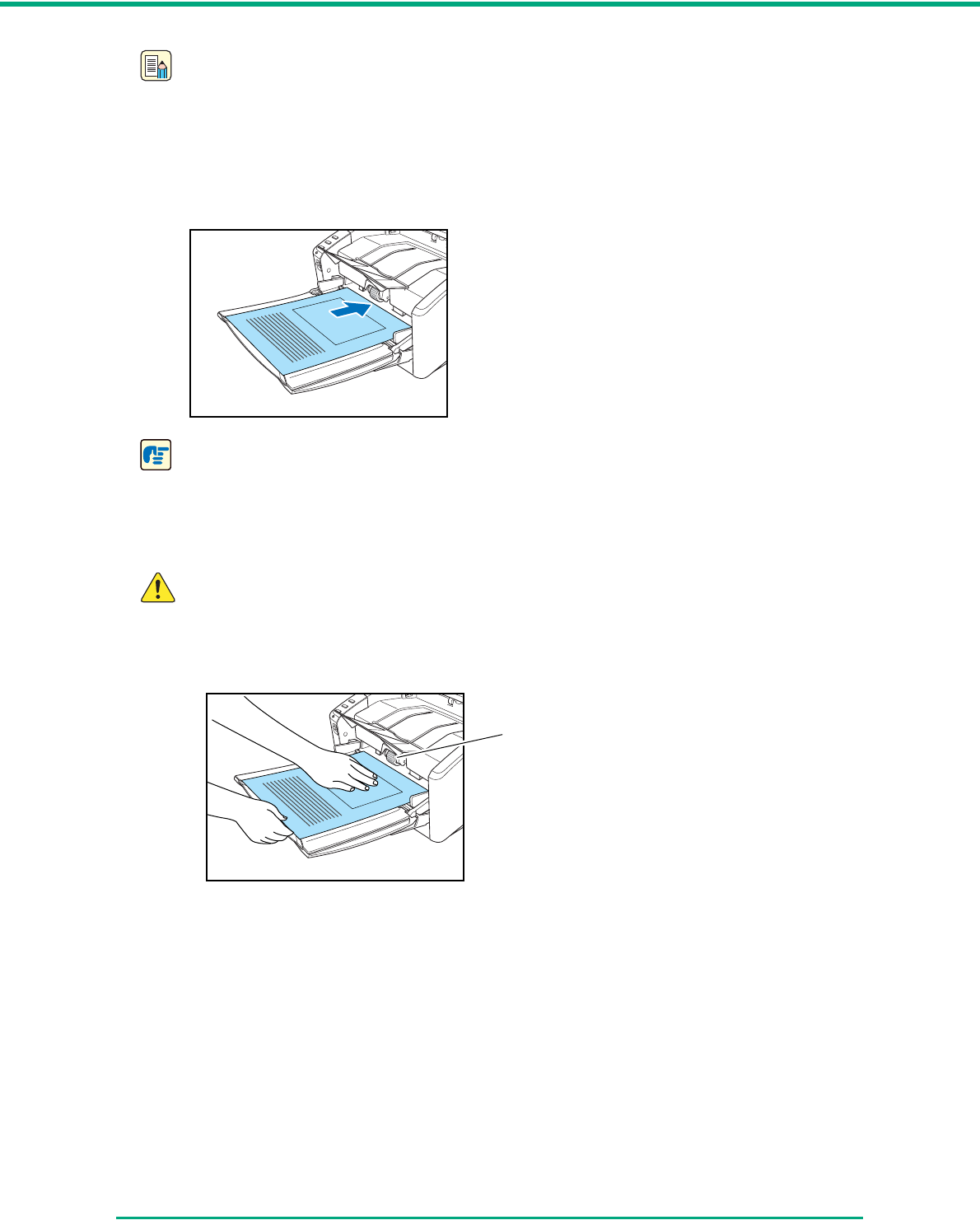
CAUTION
■Very thin or curled documents may not feed properly. In this case, lightly press on
the leading edge of the documents as you feed them. Take care not to get your
hand caught under the roller unit, as this may cause personal injury.
■After you finish scanning, close the document feed tray and the document eject
tray extension to prevent damage to the scanner while it is not being used.
Roller Unit
Chapter 3 Basic Operation
3-9
3-4 Job Function
In addition to using scanning applications, such as Capture Perfect 3.0 to perform scanning, the DR-
4010C is equipped with the Job Function. The Job Function enables you to scan simply by touching
a job button on the scanner.
This section provides an overview of the Job Function and describes the steps for using it.
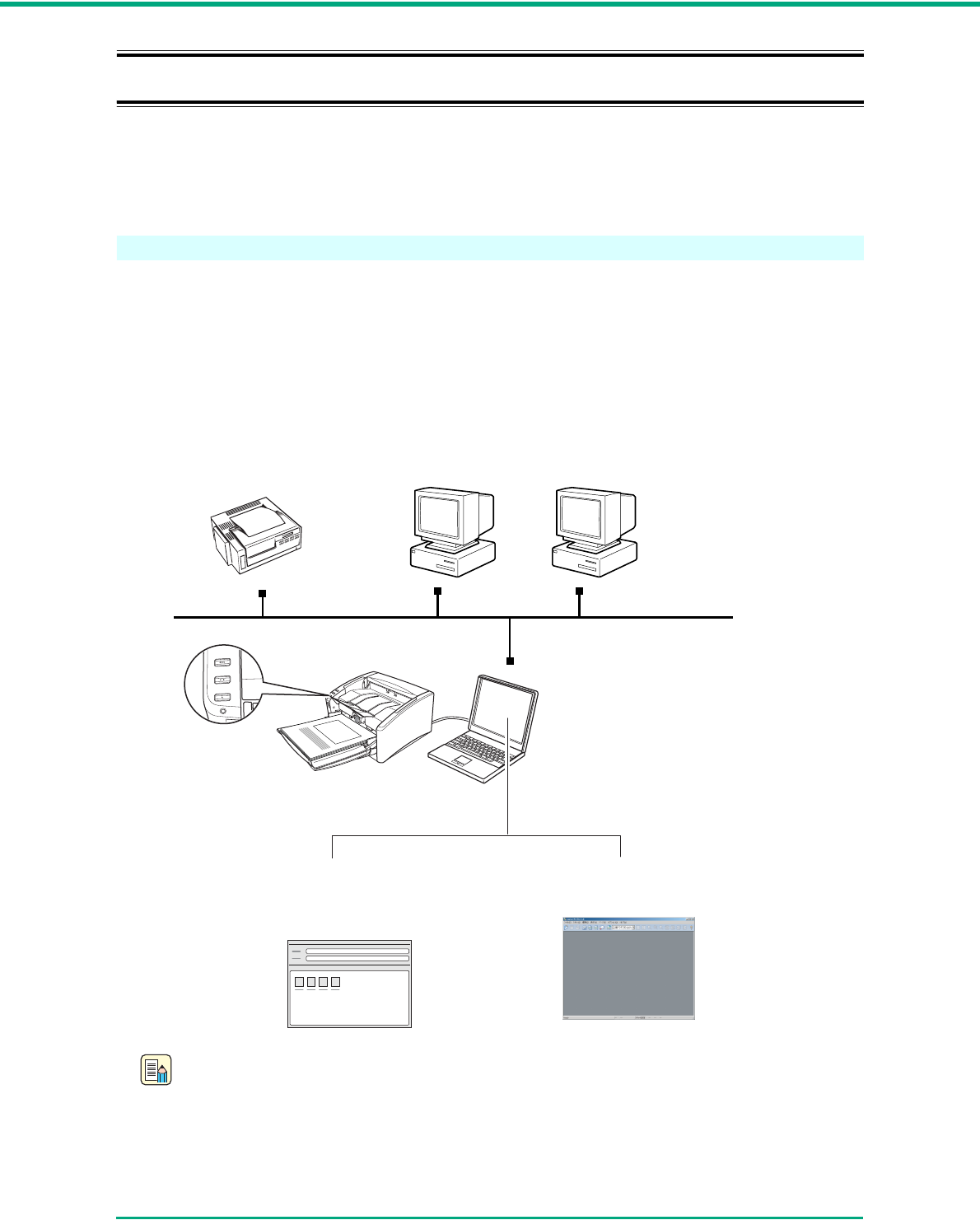
What is the Job Function ?
The Job Function enables you to program the job buttons to scan documents without having to start
an application on the computer. The scanned image data are automatically processed according to
instructions that you specify using the Job Registration tool. (See “Job Registration Tool,” on p. 3-
10.)
The follwing functions can be programmed in a job button in addition to the Start and Stop functions:
Note
To use the Launcher function, you must first change the Windows event settings. (See “About
Launcher,” on p. 3-11.)
Print
Send the scanned image data
to print on a specified printer.
Save as file
Save the scanned image data as a
file in a specified folder.
(Network)
Job Buttons
DR-4010C
Send by E-Mail
Start up your e-mail program,
and attach the scanned image
data to a new e-mail message.
Launcher
Start up a specified application program.
Chapter 3 Basic Operation
3-10
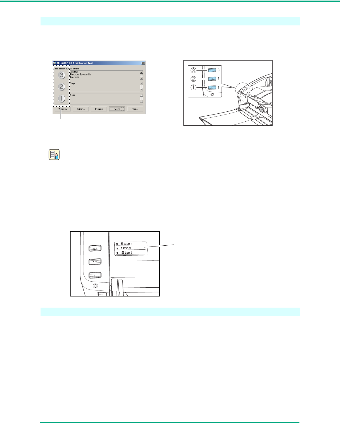
Job Registration Tool
The Job Registration Tool is a TWAIN-compatible application that is installed with the ISIS/TWAIN
driver, and launches from the Programs menu. Use the Job Registration Tool to program functions in
the job buttons.
For information about Job Registration Tool settings, see Chapter 8, “Job Registration Tool Settings,”
as well as the online help for the Job Registration Tool.
Note
• The following jobs are preset, however, they can be changed to suit your needs.
a Start: Starts scanning according to the application settings.
b Stop: Stops scanning.
c Save as file: Saves scanned image data as PDF files in the [My Pictures] folder.
• If you assign scan functions to all three job buttons on the scanner, use the Start and Stop
buttons on the Scan Panel to start or stop scanning. (See “Scan Panel,” on p. 3-21.)
• Write the assigned functions for each job button on the supplied job label and attach it to the
scanner for your reference.
Scanning With the Job Function
To scan using the job function, use the following procedure.
Job Buttons
Job Button Settings
Job Label
Chapter 3 Basic Operation
3-11
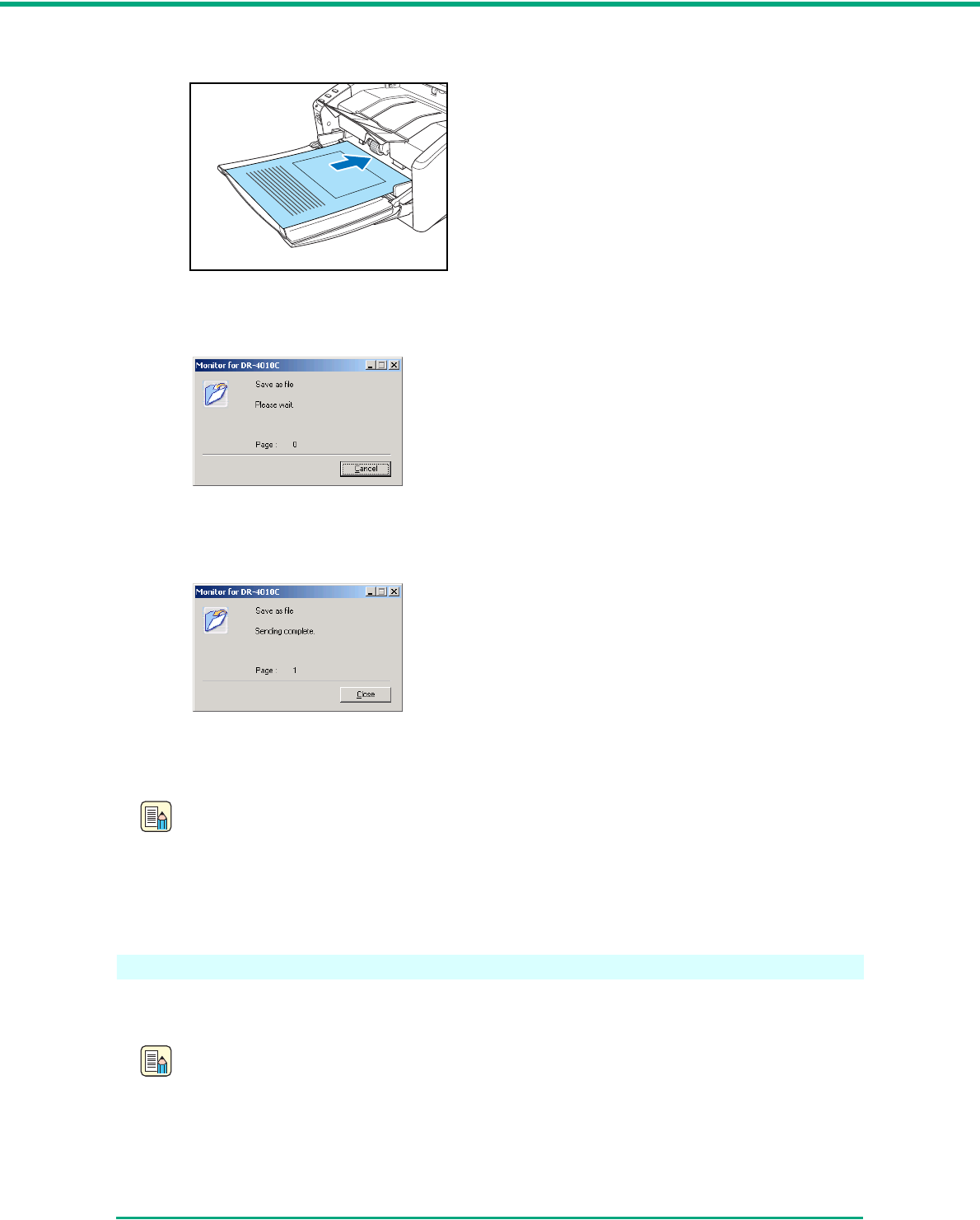
1Place the documents into the feed tray. (See “3-3 Placing Documents,” on p. 3-5.)
2Press the job button c to start the job.
The DR-4010C monitor appears, and scanning starts.
3When scanning is complete, the image data are sent according to the preset conditions.
The message <Sending complete> appears on the DR-4010C monitor.
4Click [Close] to close the DR-4010C monitor.
Note
• The default setting for job button c after the DR-4010C setup is completed is “Scan.”
• The scanned images are saved as PDF files in the folder [My Pictures] under the folder [My
Documents]. The file name is a 17-character string using the date and time when the
document is scanned.
About Launcher
To use the Launcher feature, it is necessary to first change the Windows event settings as described
below, and specify an application for each job button.
Note
• By default, all applications supporting the event function are enabled. If you do not change
the event setting before you use the Launcher feature of the DR-4010C, the dialog box
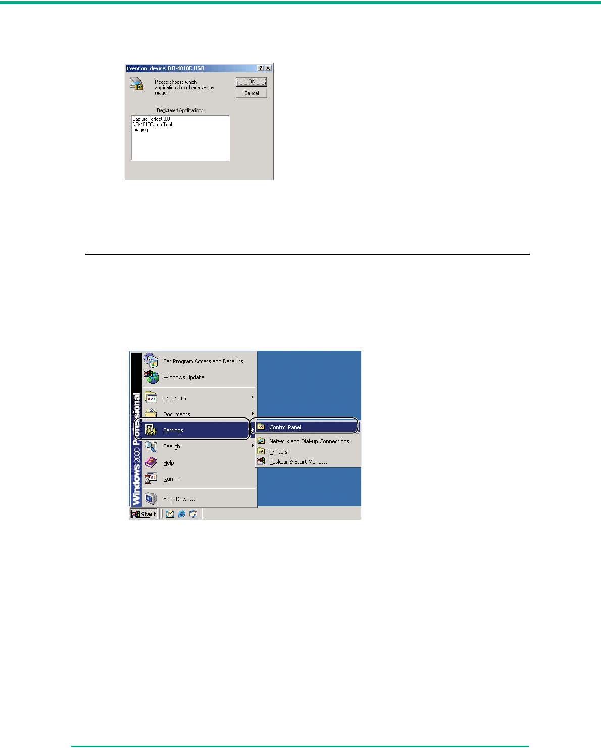
Chapter 3 Basic Operation
3-12
shown below will appear. Select an application from this dialog box or click [Cancel] and
change the event settings.
• Only applications that support the Windows event function can be started using the
Launcher feature of the DR-4010C.
• Some applications may not work correctly if started using the Launcher feature.
Event Settings
This section describes how to change the Windows event settings.
1Open the [Event settings] dialog box.
1. Click [Start] Æ click [Settings] on the [Start] menu Æ click [Control Panel]. (For Windows
XP, click [Start] Æ [Control Panel].)
2. For Windows XP, switch the Control Panel to Classic View, or select [Printers and Other
Hardware] in the working field.
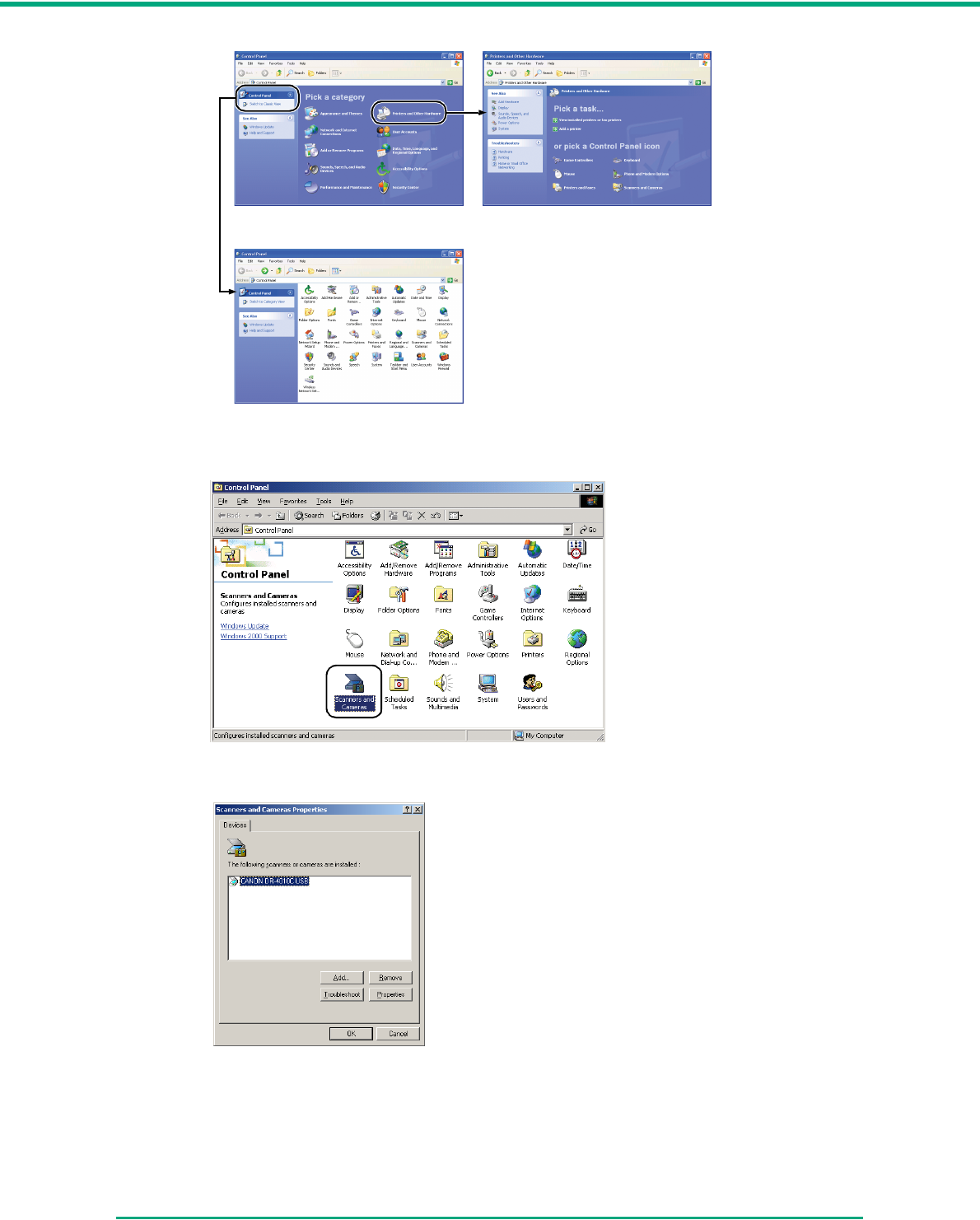
Chapter 3 Basic Operation
3-13
3. Double-click [Scanners and Cameras].
4. Select [CANON DR-4010C USB] (or [CANON DR-4010C SCSI]) Æ click [Properties].
The [CANON DR-4010C USB Properties] (or [CANON DR-4010C SCSI Properties])
window appears.
Printers and Other HardwareControl Panel (Category View)
Control Panel (Classic View)
Chapter 3 Basic Operation
3-14
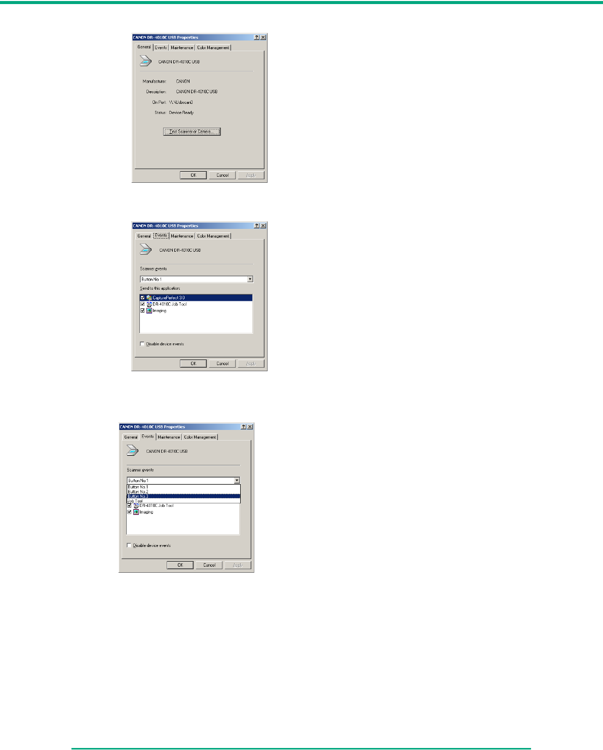
5. Click the [Events] tab.
2Under [Scanner events], select the button whose setting you want to change (Button No. 1,
Button No. 2, Button No. 3.)
Chapter 3 Basic Operation
3-15
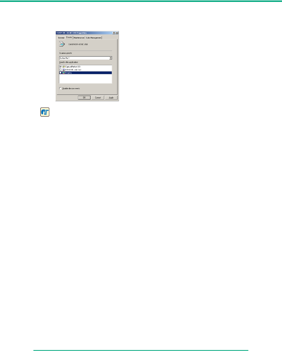
3By default, all applications listed under [Send to this application] are selected. Select only one
application (deselect the check boxes for all other applications.) Then click [Apply].
IMPORTANT
If the [Disable device events] check box is selected, the Job Function cannot be used. Make
sure that this check box is not selected.
4Click [OK] to close [Scanners and Cameras Properties].
5Restart Windows to enable the new event settings.
Chapter 3 Basic Operation
3-16
3-5 CapturePerfect 3.0
This section describes the flow of the CapturePerfect 3.0 application.
For more information on CapturePerfect 3.0, see the CapturePerfect 3.0 Operation Guide and the
CapturePerfect 3.0 online Help. Familiarize yourself with CapturePerfect 3.0 by reading these
sources before using the application.
What is CapturePerfect 3.0
CapturePerfect 3.0 is an ISIS-compatible application developed for Canon document scanners.
CapturePerfect 3.0 includes the following modes. Select the desired scan mode from the Scan menu
to perform scanning.
Scan Batch to File
Documents are scanned with the preset scanning conditions, and the scanned image data is
saved to a specified folder.
Scan Batch to Print
Documents are scanned with the preset scanning conditions, and the scanned image data is
printed on a specified printer.
Scan Batch to Mail
Documents are scanned with the preset scanning conditions, the e-mail software application is
started, and the scanned image data is attached to a new e-mail message.
Scan Page
Only one page of the document is scanned.
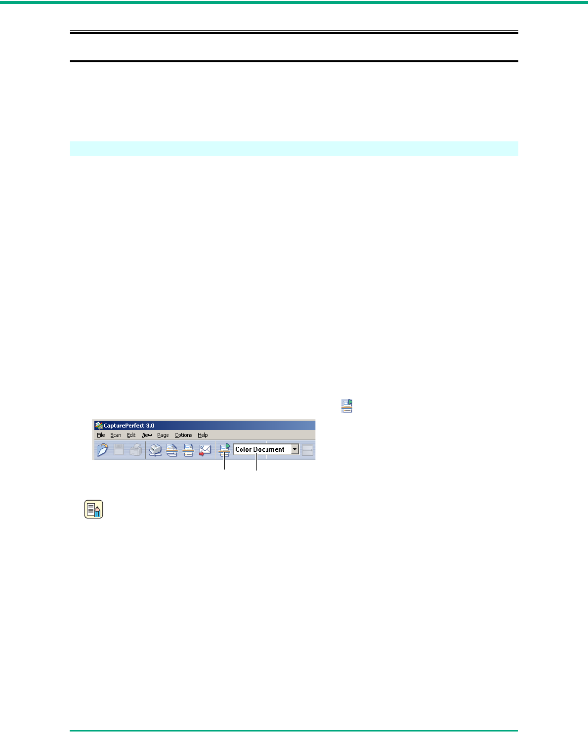
Scan Job
The scanning conditions and scan mode (Scan Batch to File, Scan Batch to Print, or Scan Batch
to Mail) are registered in advance as a job. The scan job can then be performed by selecting the
registered job from the drop-down list (a) or by pressing (Scan Job) on the toolbar (b).
Note
The following two scan jobs are already registered.
• Color Document
Scan the document using 24-bit color, simplex, at 300 dpi resolution, and save the file in the
folder [My Pictures] under the folder [My Documents].
• Binary Document
Scan the document in black-and-white, simplex, at 200 dpi resolution, and save the file in
the folder [My Pictures] under the folder [My Documents].
b a
Chapter 3 Basic Operation
3-17
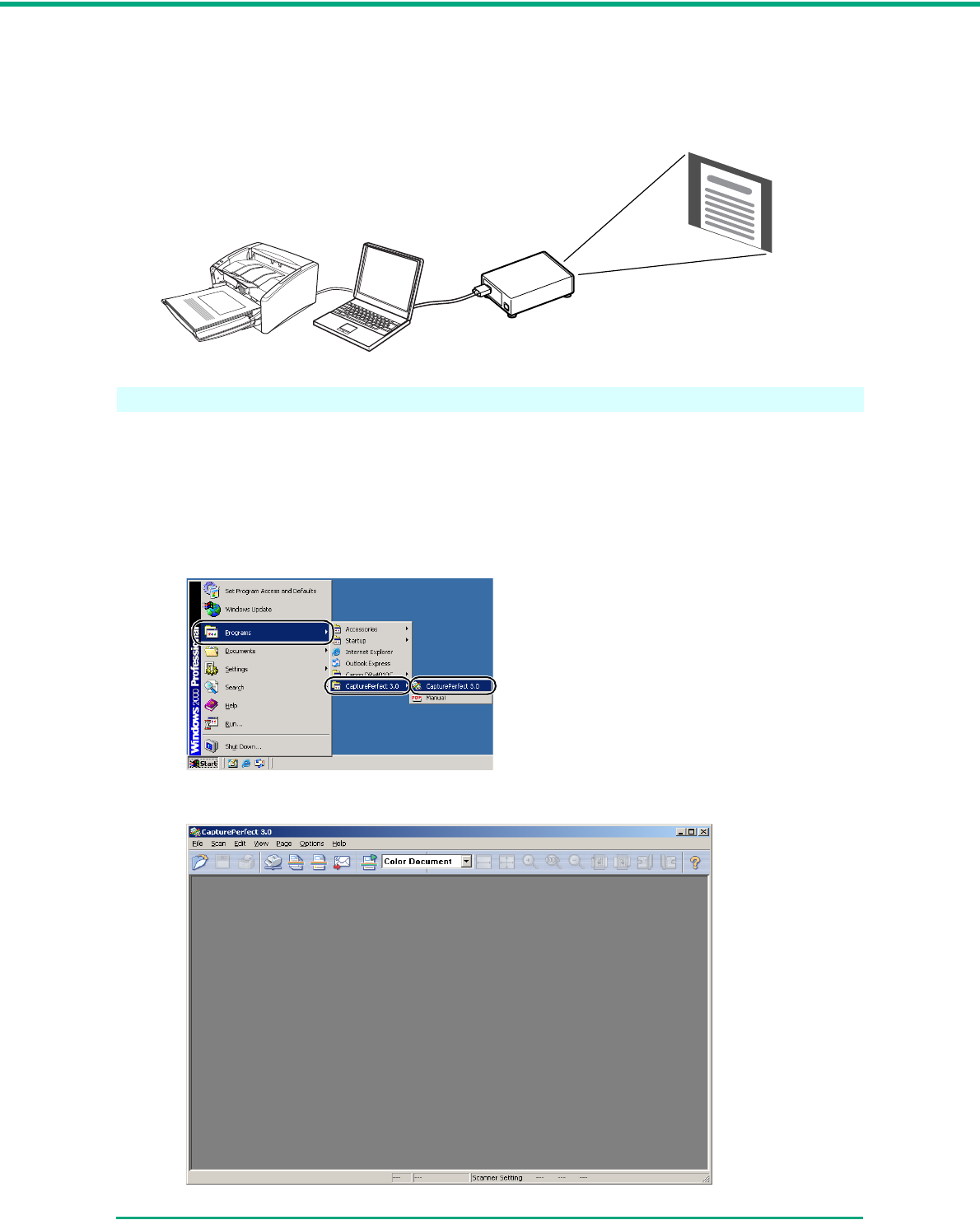
• Scan To Presentation
This mode is useful when the scanner is used in environments, such as conference halls, where it
can be connected to large displays or projectors. CapturePerfect 3.0 is switched to full-screen
display, the document is scanned, and the scanned image is displayed at full size on the screen.
Using CapturePerfect 3.0
This section describes how to start up CapturePerfect 3.0, select the scanner, and scan documents.
The Scan Batch to File function is used here as an example.
For details, see the CapturePerfect 3.0 Operation Guide and CapturePerfect Online Help.
1Click the Windows [Start] button Æ click [Programs] ([All Programs] for Windows XP) Æ
[CapturePerfect 3.0] Æ [CapturePerfect 3.0].
CapturePerfect 3.0 starts up.
DR-4010C
Projector
The scanned image is
projected on the screen.
Chapter 3 Basic Operation
3-18
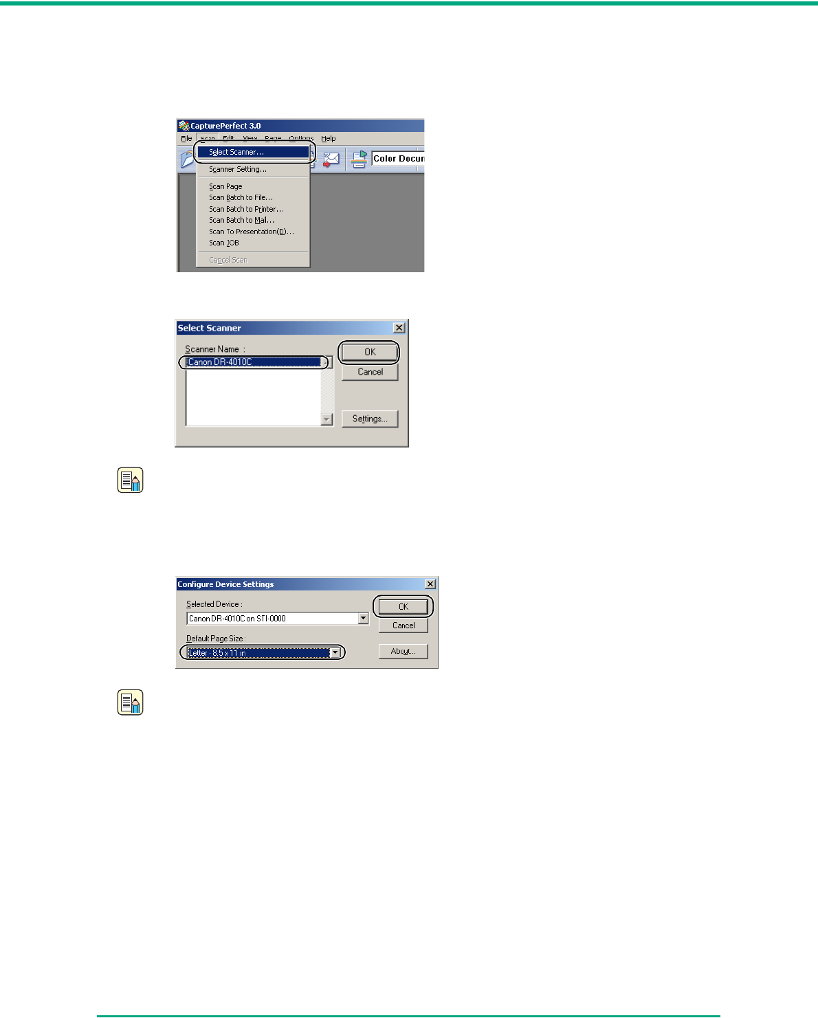
2Follow the procedure below to select the Canon DR-4010C Document Scanner as the
scanner to be used.
1. On the [Scan] menu, click [Select Scanner].
2. Select [Canon DR-4010C] Æ click [OK].
Note
If [Canon DR-4010C] is not displayed in the list of scanners, re-install the ISIS/TWAIN driver.
(See “2-3 Installing the Software,” on p. 2-4.)
3. Set the Default Page Size and click [OK].
Note
This dialog box is displayed only when you select [Canon DR-4010C] for the first time and
click [OK], or when you click [Setup] for [Scanner Selection].
Chapter 3 Basic Operation
3-20
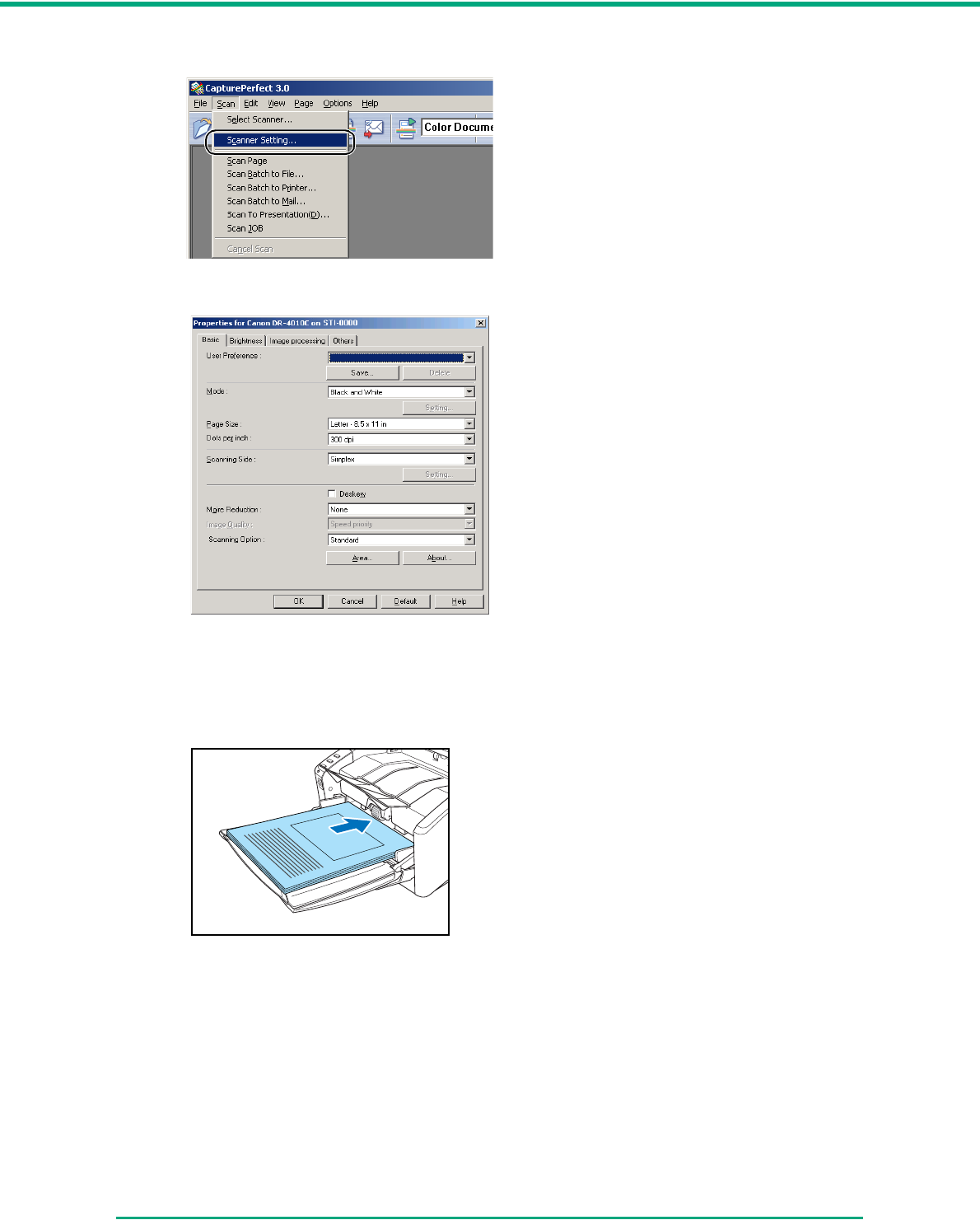
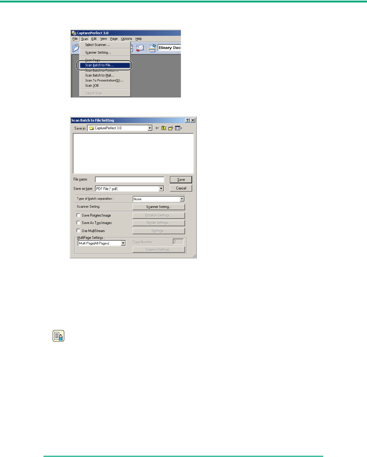
6On the [Scan] menu, select [Scan Batch to File].
The [Scan Batch to File Setting] dialog box opens.
For more details on how to scan documents, see the CapturePerfect 3.0 Operation Guide and
CapturePerfect Online Help.
7Specify the file name and the file type for saving the image data, and click [Save] to start
scanning.
For details on the available settings in the [Scan Batch to File Setting] dialog box, see the
CapturePerfect 3.0 Operation Guide and CapturePerfect Online Help.
Note
If Feeding Option in the scan settings is set to “Panel-Feeding” or “Automatic Feeding,” the
scan panel will appear when you start scanning. (See “Scan Panel,” on p. 3-21.)
8When there are no more pages of the document to scan, scanning stops. Scanning resumes
or ends according to the Feeding Option setting in the scanner setup.
• Feeding Option is set to “Standard Feeding”:
The Continue dialog box is displayed. Place the next document, and click [Continue
scanning] to resume scanning, or click [Stop Scanning] to end scanning.
• Feeding Option is set to “Automatic Feeding”:
Place the next document. Scanning resumes when the scanner detects the document.
Alternatively, press job button b (Stop) to stop scanning.
Chapter 3 Basic Operation
3-21
• Feeding Option is set to “Panel-Feeding”:
Place the next document and press job button a (Start) to resume scanning, or press job
button b (Stop) to stop scanning.
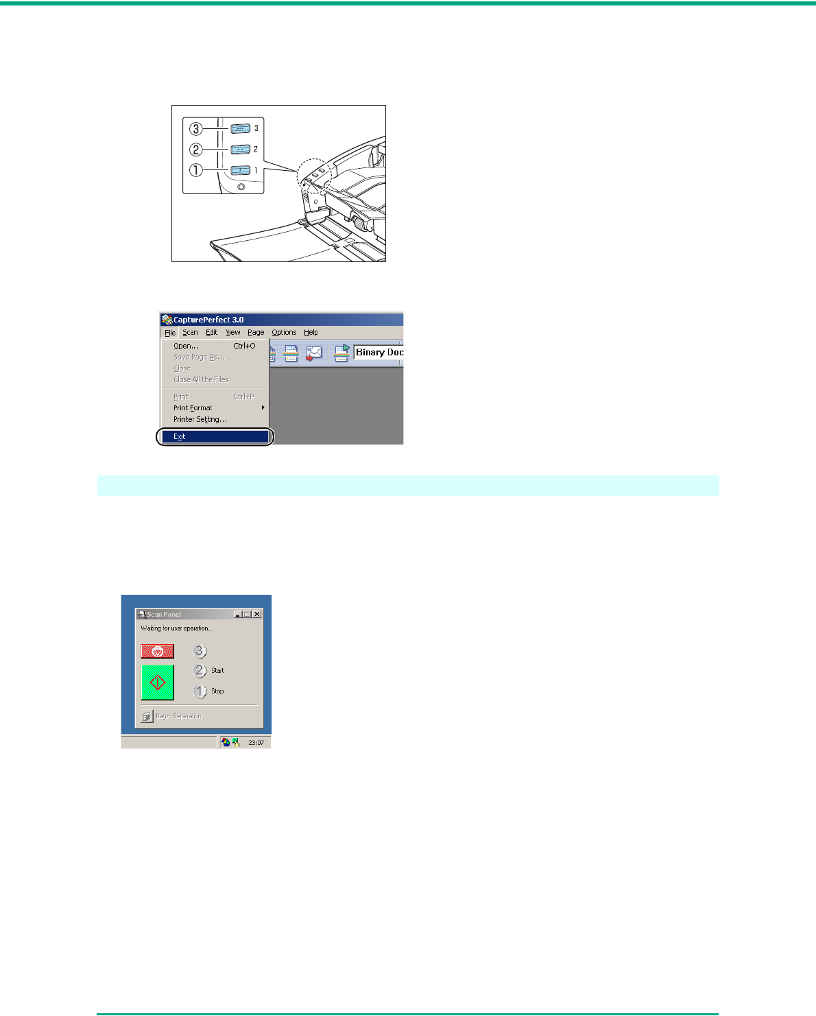
9After scanning is complete, select [Exit] on the [File] menu to quit CapturePerfect 3.0.
Scan Panel
The Scan Panel is an application that is installed with the ISIS/TWAIN driver. When the DR-4010C
driver starts, the scan panel appears in the task tray.
If Feeding Option in the scan settings is set to “Panel-Feeding” or “Automatic Feeding,” the Scan
Panel will appear when you start scanning.
Job buttons
Chapter 3 Basic Operation
3-22
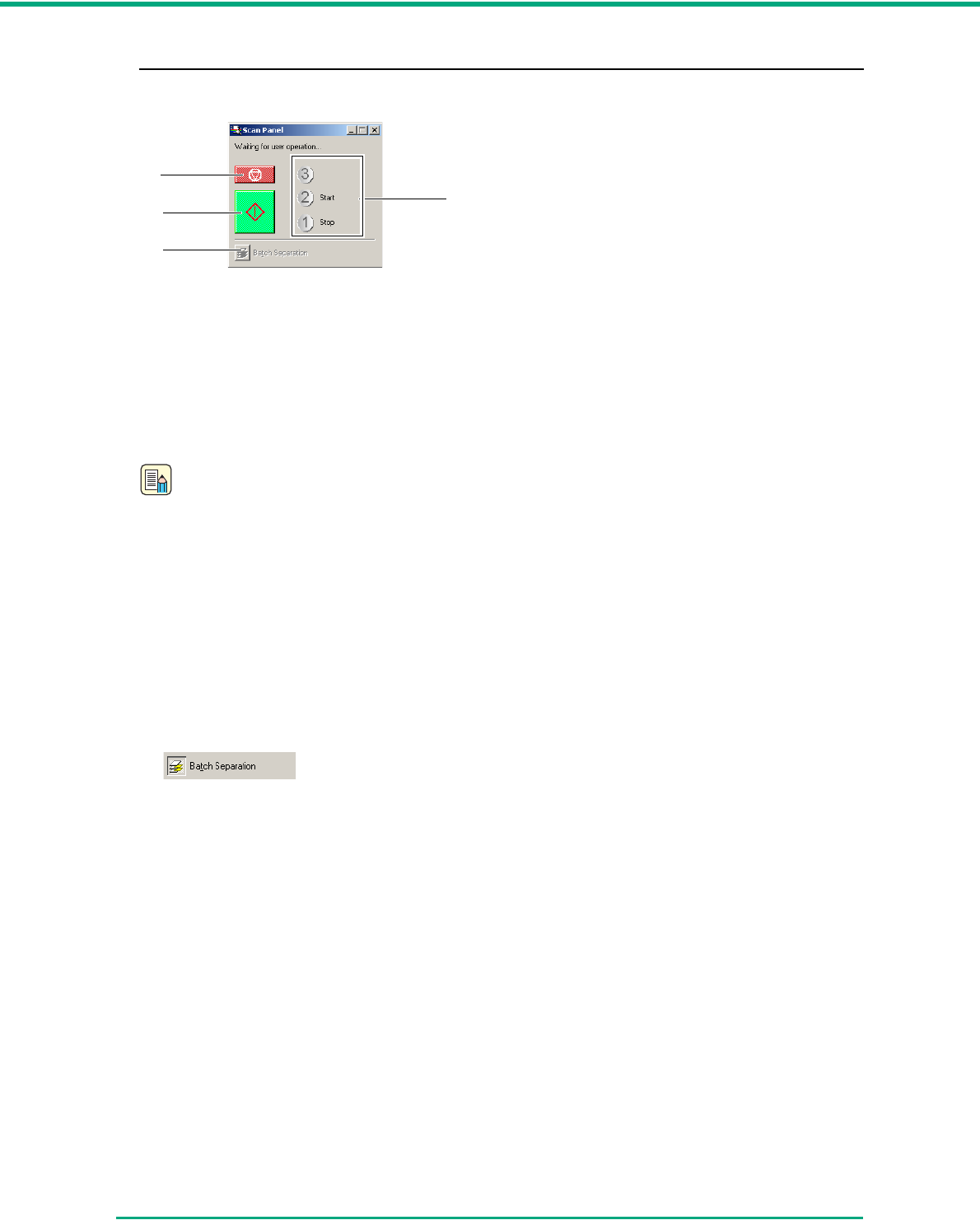
Scan Panel Functions
The Scan Panel has the following functions.
a Start button
If Feeding Option is set to “Panel-Feeding,” clicking this button starts scanning.
b Stop button
Stops scanning.
c Job display
When the Start and Stop functions are assigned to the job buttons, [Start] and [Stop] are shown
here.
Note
If nothing is shown on the job display, the Start and Stop functions are not assigned to the job
buttons. In this case, you should use the Start and Stop buttons on the Scan Panel.
d Batch separation button
After selecting [Panel] as the batch separation setting on the [Others] tab, if you enable batch
separation from the application and start scanning, this button becomes active when scanning of
the current document completes, and scanning stops.
When clicked, this button depresses and remains depressed while scanning with batch
separation continues, until scanning of the current document completes, and scanning stops.
The button then returns to normal.
a
b
c
d
Chapter 3 Basic Operation
3-23
3-6 Using Patchcode Sheets
The DR-4010C ISIS driver and CapturePerfect 3.0 both support the automatic file separation
function with patchcode sheets.
Patchcode patterns are printed on patchcode sheets, which are used to automatically separate files.
When the scanner recognizes a patchcode sheet during scanning, the files are automatically
separated at the patchcode sheet or at the image data of the next document.
Note
• The TWAIN driver does not support batch separation.
• Patchcode sheets can be used only when the ISIS compatible application supports
separating files by patchcode patterns.
• Patchcode sheets cannot be used when the MultiStream function (See “MultiStream
Function,” on p. 3-34.) is being used.
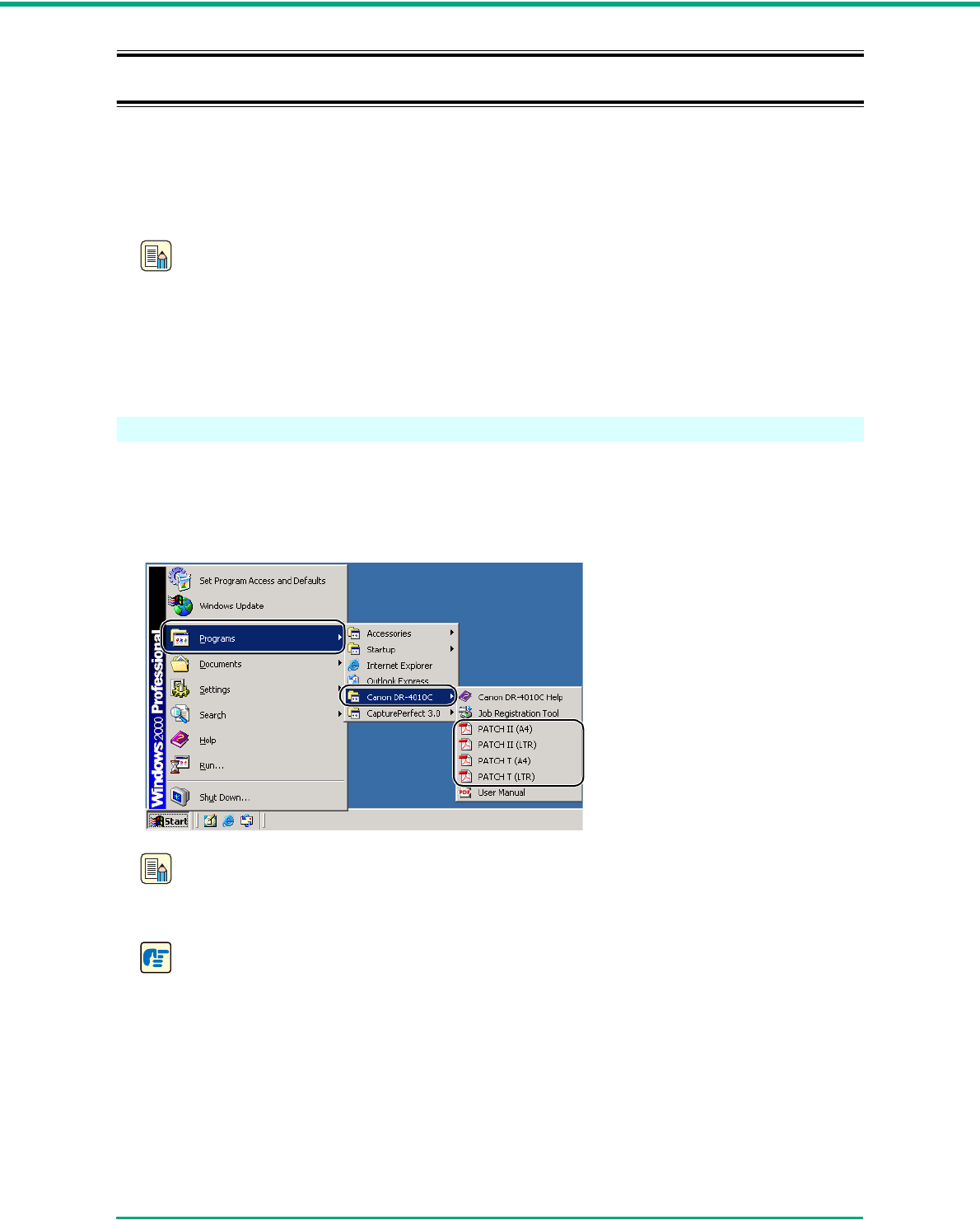
About Patchcode Sheets
Patchcode sheets are data in a portable document format (PDF.) There are four types; [PATCH II
(A4)], [PATCH II (LTR)], [PATCH T (A4)], [PATCH T (LTR)] according to the paper size and pattern.
Click on the Windows start button, open [Programs] Æ [Canon DR-4010C] Æ [PATCH X (XX)]. Print
the patchcode sheet to use it for scanning.
Note
To open patchcode sheets you need CapturePerfect 3.0, which is provided with the scanner,
or an application, which supports PDF format files.
IMPORTANT
Patchcode sheets must be printed in their original size. The scanner may not recognize them
as patchcode sheets if they are enlarged or reduced.
Chapter 3 Basic Operation
3-24
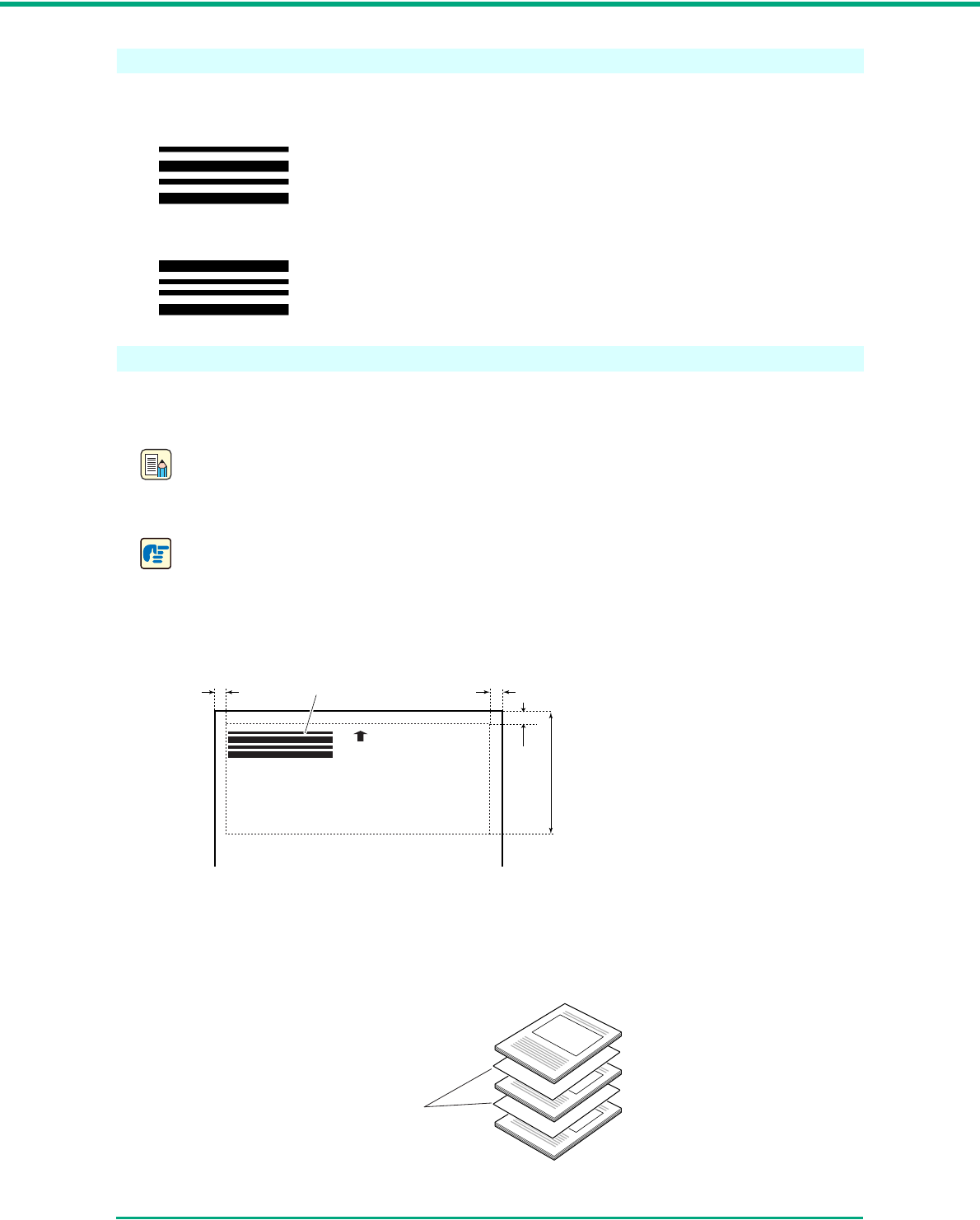
Patchcode Pattern Function
There are two types of patchcodes and their function changes according to their pattern.
■PATCH T (FILE A)
PATCH II (FILE B)
How to Use Patchcode Sheets
1Print patchcode sheets on a printer. Print the patchcode sheets at their original size on paper
that is the same size as the image data.
Note
• Print [PATCH II (A4)] and [PATCH T (A4)] on A4 paper.
• Print [PATCH II (LTR)] and [PATCH T (LTR)] on LTR paper.
IMPORTANT
To copy a patchcode pattern to create a different size patchcode sheet, make sure to pay
attention to the following:
• Adjust the patchcode so that it fits into the effective area for detecting patchcode patterns.
• When copying a patchcode pattern, the copy should be the same size and print density as
the pattern on the original. Extremely dark or light copies may not be scanned correctly.
2Insert the patchcode sheet in front of the document that you want to save as a separate file
before placing the documents on the scanner.
When the scanner recognizes this patchcode printed on a patchcode sheet,
it creates a separate file for the document that comes after the patchcode
sheet. The image of this sheet can be saved or not, depending on the
application’s settings.
When the scanner recognizes this patchcode printed on a patchcode sheet,
it creates a separate file starting from the patchcode sheet. The image of this
sheet is saved, regardless of the application’s settings.
(Effective area for detecting
patchcode patterns.)
0.2" (5 mm)0.2" (5 mm) Patchcode Patterns
0.2"
(5 mm)
3.7"
(94 mm)
Insert patchcode sheets in front
of the documents you want to
save as separate files.
Chapter 3 Basic Operation
3-25
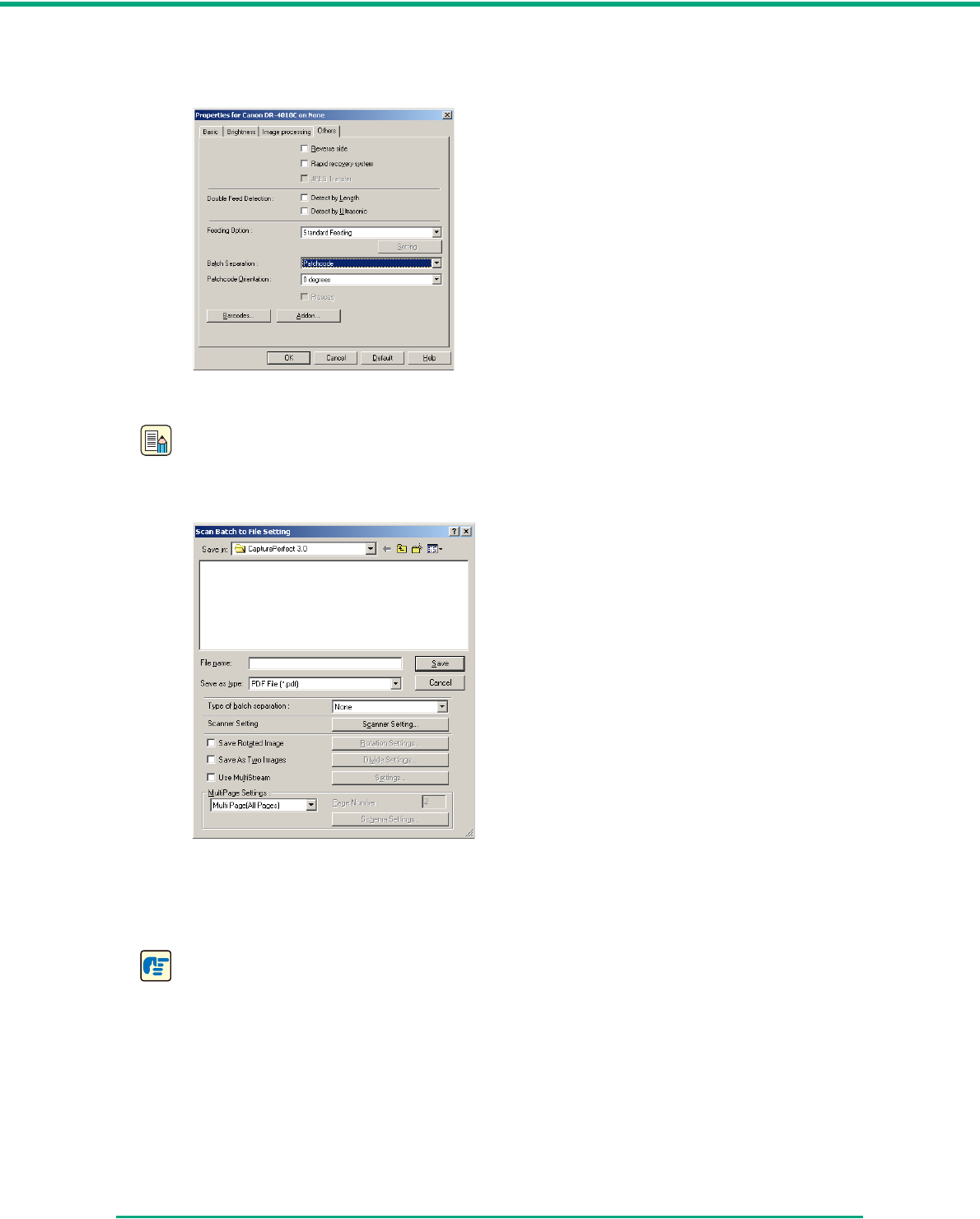
3On the [Other] tab of the ISIS driver properties, set the batch separation setting to
“Patchcode.”
4From the application, perform scanning with batch separation enabled.
Note
If you are scanning with CapturePerfect, set the Type of batch separation setting to “Scan,
Continue Scanning” or “Skip, Continue Scanning.”
• If “Scan, Continue Scanning” is selected, the patchcode sheet image is also saved and
scanning continues.
• If “Skip, Continue Scanning” is selected and the PATCH T (FILE A) pattern is detected, the
patchcode sheet image is not saved and scanning continues.
IMPORTANT
Make sure to keep the patchcode sheets clean. In particular, the effective area for detecting
patterns should be kept clean. Also, do not fold them or allow them to become creased. If this
happens, the scanner will not be able to read them.
Chapter 3 Basic Operation
3-26
3-7 Clearing a Paper Jam
When paper jams occur during scanning, use the following procedure to clear them.
CAUTION
When removing jammed paper, take care not to cut your hands on the edges of the
paper.
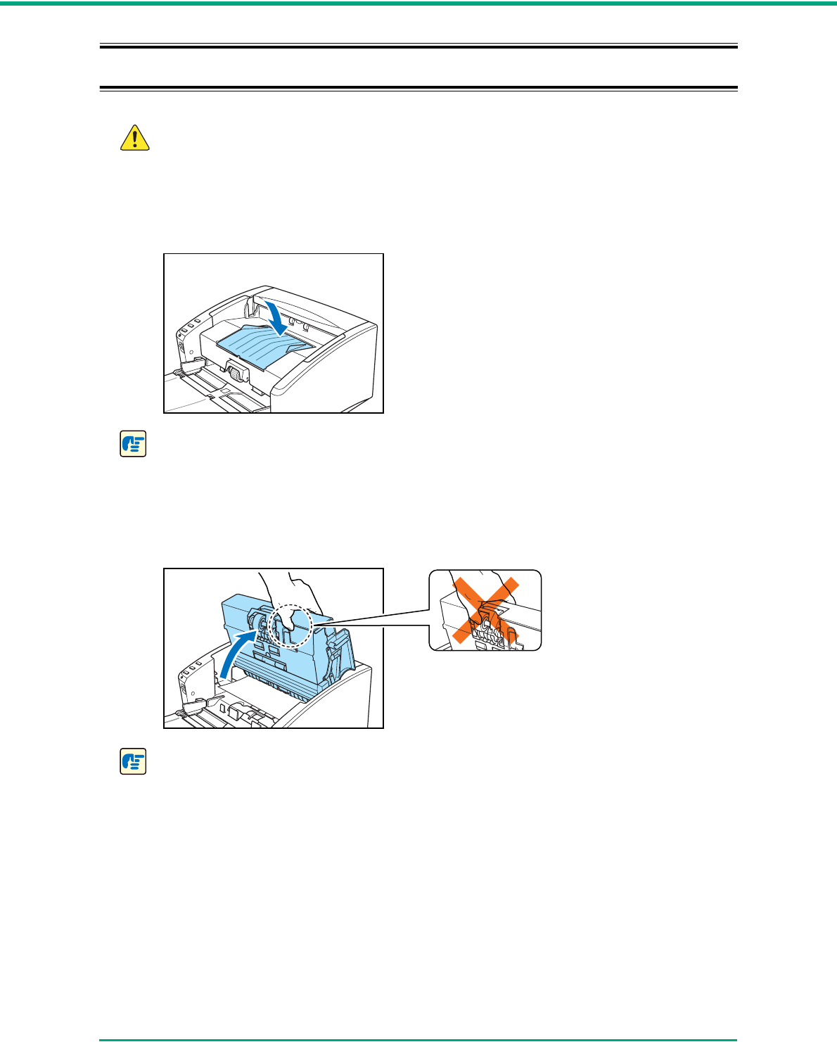
1Remove any documents that have been left in the eject tray, and close the eject tray guide.
IMPORTANT
If a document stops in the eject tray, remove the document before closing the document eject
tray extension. Attempting to force the document eject tray extension closed may damage the
document.
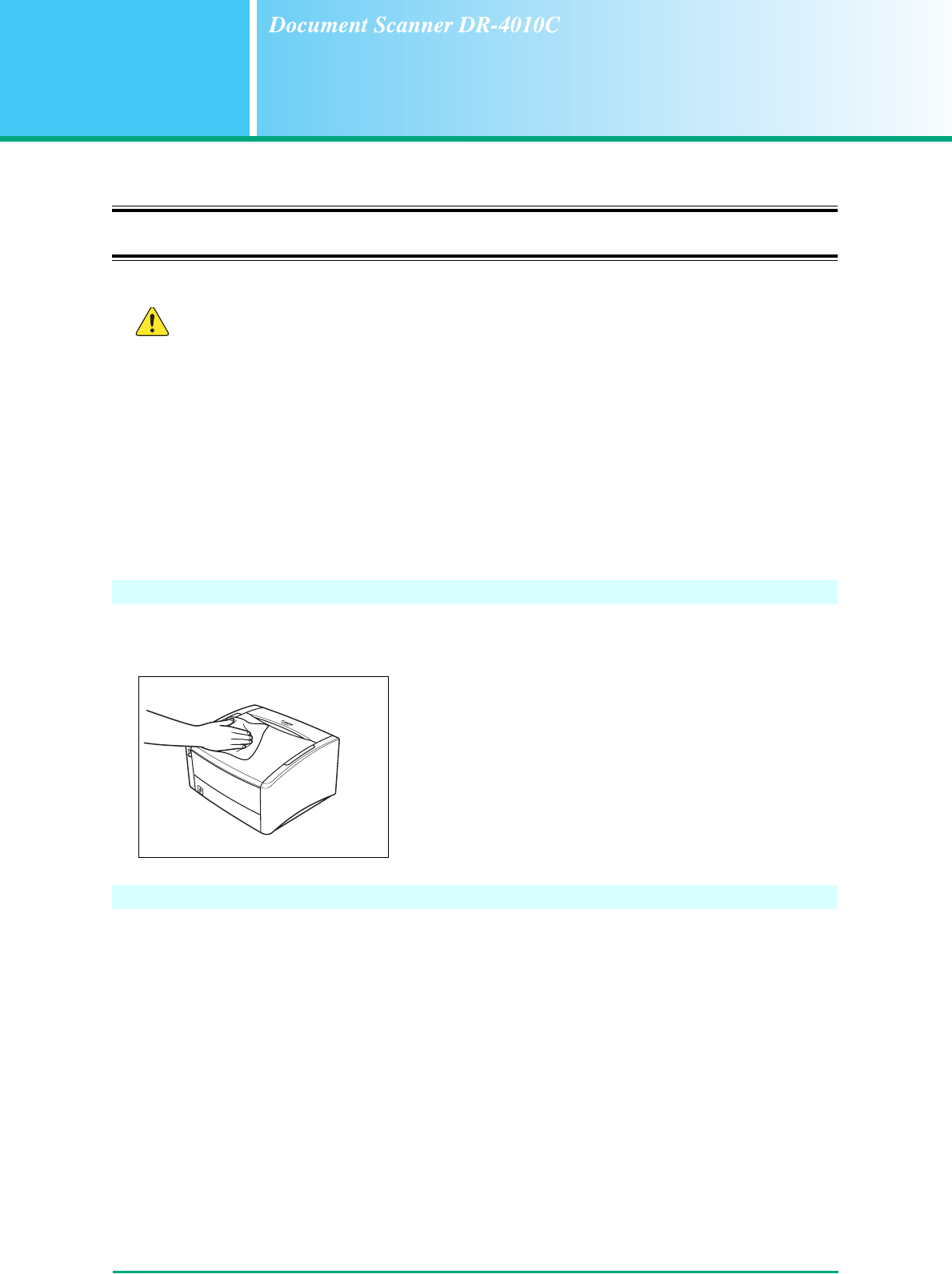
2Carefully open the upper unit until the jammed document can be removed.
IMPORTANT
When opening the upper unit, do not grasp the roller unit in the center. Doing so may distort
the rollers and lead to feeding errors.
Chapter 3 Basic Operation
3-27
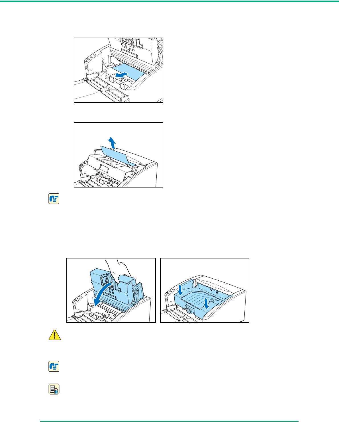
3Remove the jammed document.
■If the jam occurred in the feed section
■If the jam occurred in the eject section
IMPORTANT
Make sure to pull the document out carefully, without applying too much force.
If jammed paper tears while it is being removed, make sure to remove any remaining pieces
from inside the scanner.
4Close the upper unit slowly. Make sure that the upper unit is completely closed by pushing on
both edges with both hands until you hear a click.
CAUTION
When closing the upper unit, be careful not to get your fingers caught, as this may
result in personal injury.
IMPORTANT
Do not force the upper unit to close. Doing so may damage the scanner.
Note
• After removing the jammed paper, check to see if the last page was scanned, and then
continue scanning.

Chapter 3 Basic Operation
3-28
• If a paper jam occurs when “Rapid recover system” is enabled in the ISIS/TWAIN driver
settings, the image data of the document is not saved and scanning stops. This allows you
to continue scanning from the document that caused the paper jam after the paper jam is
fixed.
Chapter 3 Basic Operation
3-29
3-8 Other Functions
This scanner also supports the scanning functions described below.
• Folio Scan
Documents larger than A4 (up to A3) can be scanned by folding them first.
•Double Feed Detection Function
The scanner will detect a double feed and stop scanning.
•Long Document Mode
Allows scanning of documents up to 39.2” (1,000 mm) in length.
•MultiStream Function
Two types of images are output from a single scanning pass.
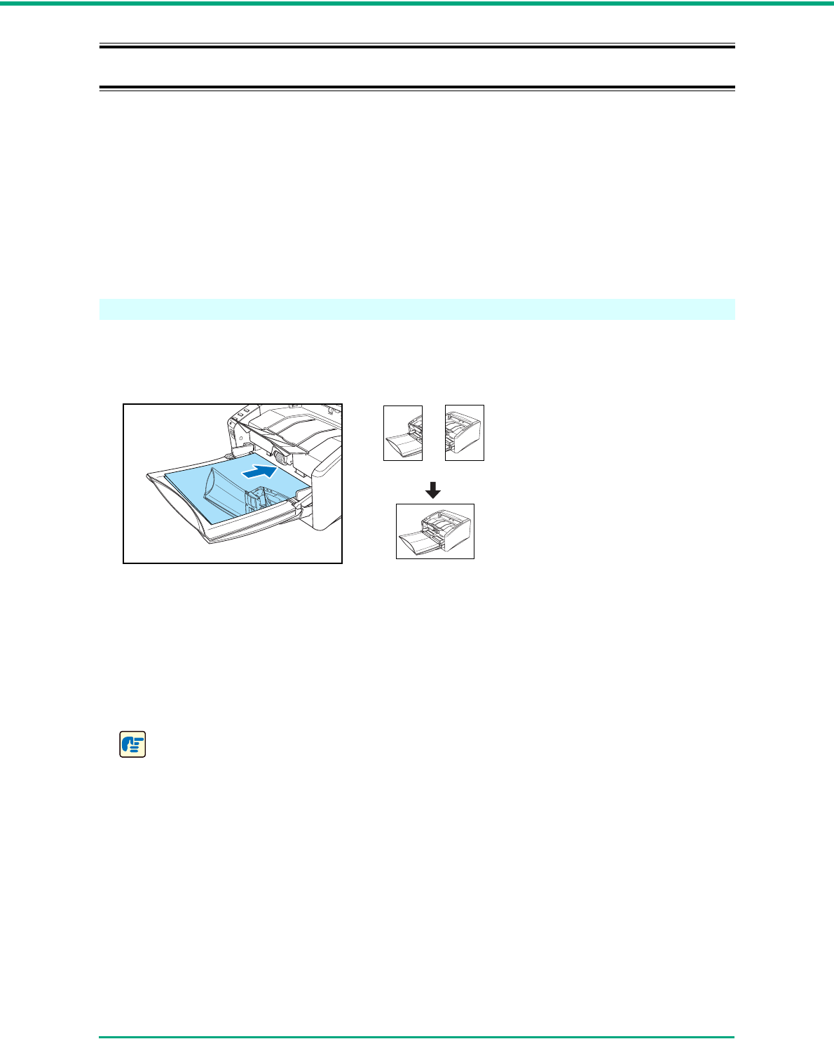
Folio Scan
This function supports the scanning of documents that are larger than A4 and therefore do not fit in
the feeder. (The maximum size is A3.) To use the function, fold the document and place it into the
feeder. The DRC-4010C will scan both sides and combine the scanned images into a single image.
• To use this function, select Folio as the “Scanning Side” setting. For details, see Chapter 7,
“ISIS/TWAIN Driver Settings.”
• The scanned image of the front side of the document becomes the left half of the combined
image.
• The maximum size for the combined image is A3. When using the Folio function for an
irregular-sized document, set Page Size to “Auto-detection.”
• When you face the front of the scanner, the fold should be on the right side.
IMPORTANT
• When folding the document, align the right and left sides and create a sharp, straight fold.
Otherwise the document may jam or the image may not be aligned properly.
• The fold line itself will not be scanned. Keep this in mind if there is content such as photos,
diagrams, or text that spans the fold.
• For Folio scanning, only bypass mode (P. 3 - 7 ) can be used.
• Adjust the document guides to fit the width of the document. Otherwise, the image may
scan as skewed or shifted.
Front Rear
Combined image
Chapter 3 Basic Operation
3-30
Double Feed Detection Function
The scanner is equipped with a [Double Feed Detection] function that automatically detects when
two or more pages are fed at the same time (double feed) while scanning continuously.
There are two methods for multiple feed detection. The detection method is selected by the ISIS/
TWAIN driver.
Detecting Double Feed by Document Length
This detection method is effective when scanning a document on pages that are all of the same
size. The length of the first page scanned is used as a standard against which the rest of the
pages are compared. If any page is 2.0" (50 mm) longer or shorter than the first page, it is
considered a double feed and scanning stops.
Detecting Double Feed with Ultrasonic Waves
This detection method is effective when scanning a document on pages that are different sizes.
Ultrasonic waves are used to detect pages that are fed at the same time as well as the space
between pages. Scanning stops if a double feed is detected.
Note
• Ultrasonic double feed detection works only when the documents overlap by 2.0" (50 mm)
or more.
• If the documents are stuck together with static electricity, the ultrasonic double feed
detection method will not correctly detect them as a double feed.
Long Document Mode
Normally, the scanner can scan documents up to 14" (356 mm) long. However, if you change the
paper size setting to Long Document mode, you can scan documents up to a maximum of 39.2"
(1,000 mm) long. (See “Long Document Mode Settings,” on p. 3-31.)
IMPORTANT
When scanning in the Long Document mode, set the paper size for the ISIS/TWAIN driver to
“Auto-detection” to allow the scanner to detect and scan documents up to 39.2" (1,000 mm)
long. Note the following when using the Long Document mode:
• Scanning documents up to 39.2" (1,000 mm) long may not be possible with some scanning
modes.
• Documents may be scanned more slowly when the scanner is scanning with automatic size
detection in Long Document mode.
Chapter 3 Basic Operation
3-31
• When scanning in the Long Document mode, if the document is placed on the scanner in a
skewed position, it may be damaged. Be careful to place the document so that it is not
skewed.
• When scanning with the Long Document mode, paper jam detection may react slowly,
resulting in damage to the document. Be careful to avoid paper jams.
• When scanning long documents, make sure to feed them one page at a time with the
bypass mode.
Long Document Mode Settings
Follow the procedure below to set the Long Document mode.
1Use the following procedure to open the [CANON DR-4010C USB Properties] (or [CANON
DR-4010C SCSI Properties].)
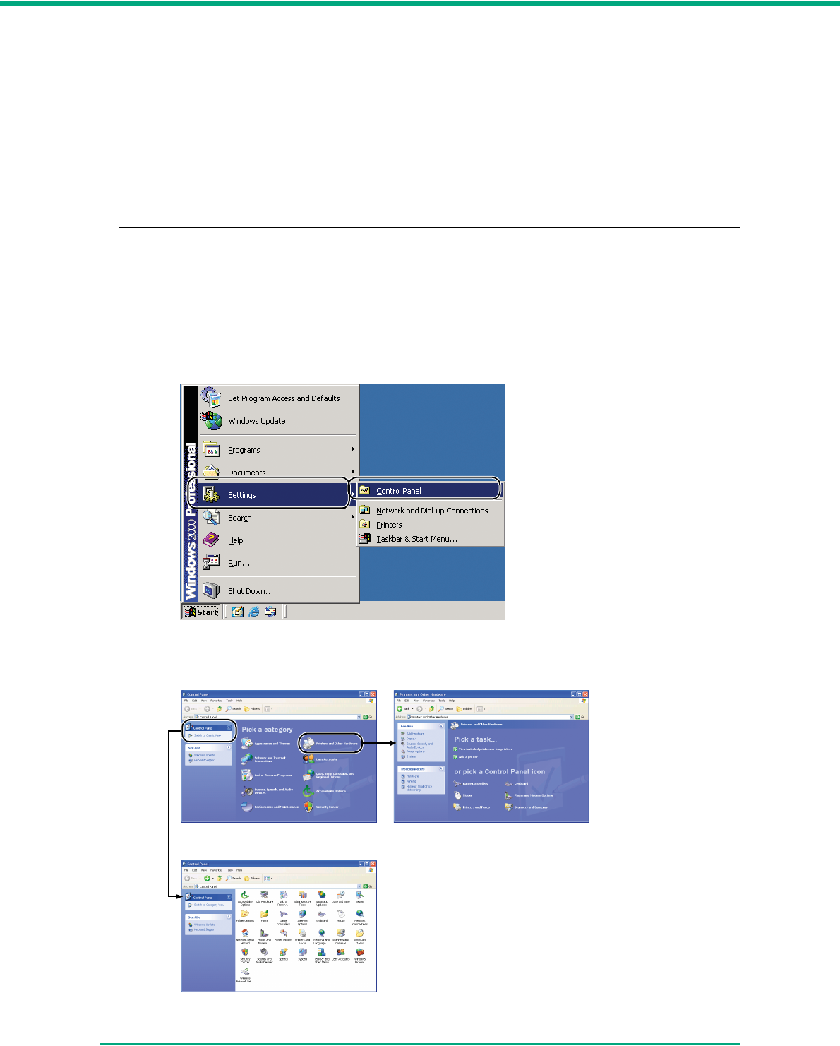
1. Click [Start] Æ [Settings] on the [Start] menu Æ click [Control Panel]. (For Windows XP,
click [Start] Æ click [Control Panel].)
2. For Windows XP, switch the Control Panel to Classic View, or select [Printers and Other
Hardware] in the working field.
Printers and Other HardwareControl Panel (Category View)
Control Panel (Classic View)
Chapter 3 Basic Operation
3-32
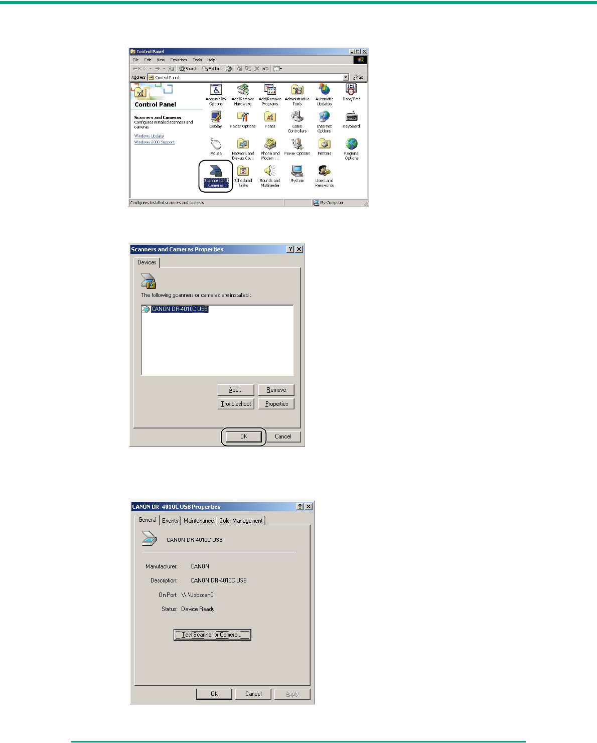
3. Double-click [Scanners and Cameras].
4. Select [CANON DR-4010C USB] or ([CANON DR-4010C SCSI]) Æ click [Properties].
The [CANON DR-4010C USB Properties] (or [CANON DR-4010C SCSI Properties])
window appears.
Chapter 3 Basic Operation
3-33
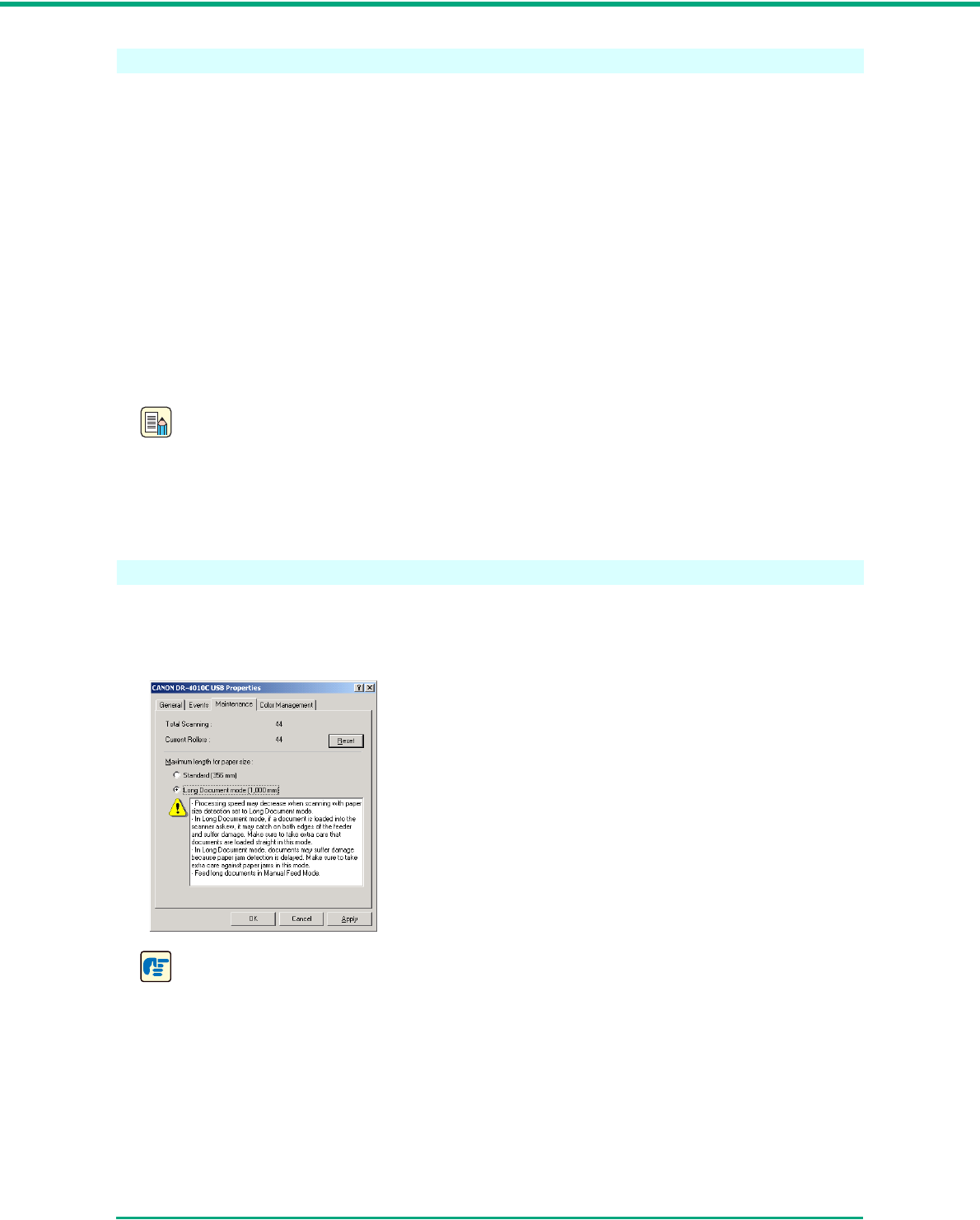
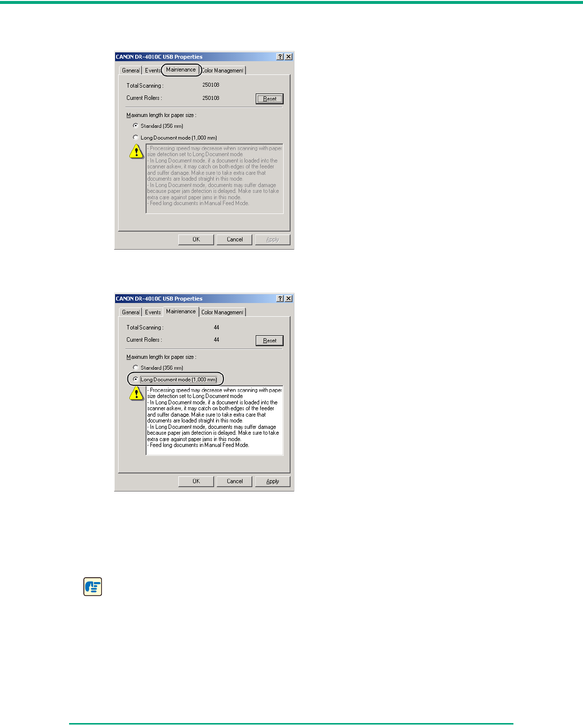
2Click the [Maintenance] tab.
3Click [Long Document mode (1,000 mm)].
4Click [Apply] to change the scanner’s settings.
5Click [OK] to close [Scanners and Cameras Properties].
6Turn the scanner OFF and then ON again.
IMPORTANT
• If you are using a SCSI connection, turn OFF the computer and then turn the scanner OFF
and then ON again.
• Wait at least 10 seconds before turning the scanner back ON after it has been turned OFF.
Chapter 3 Basic Operation
3-34
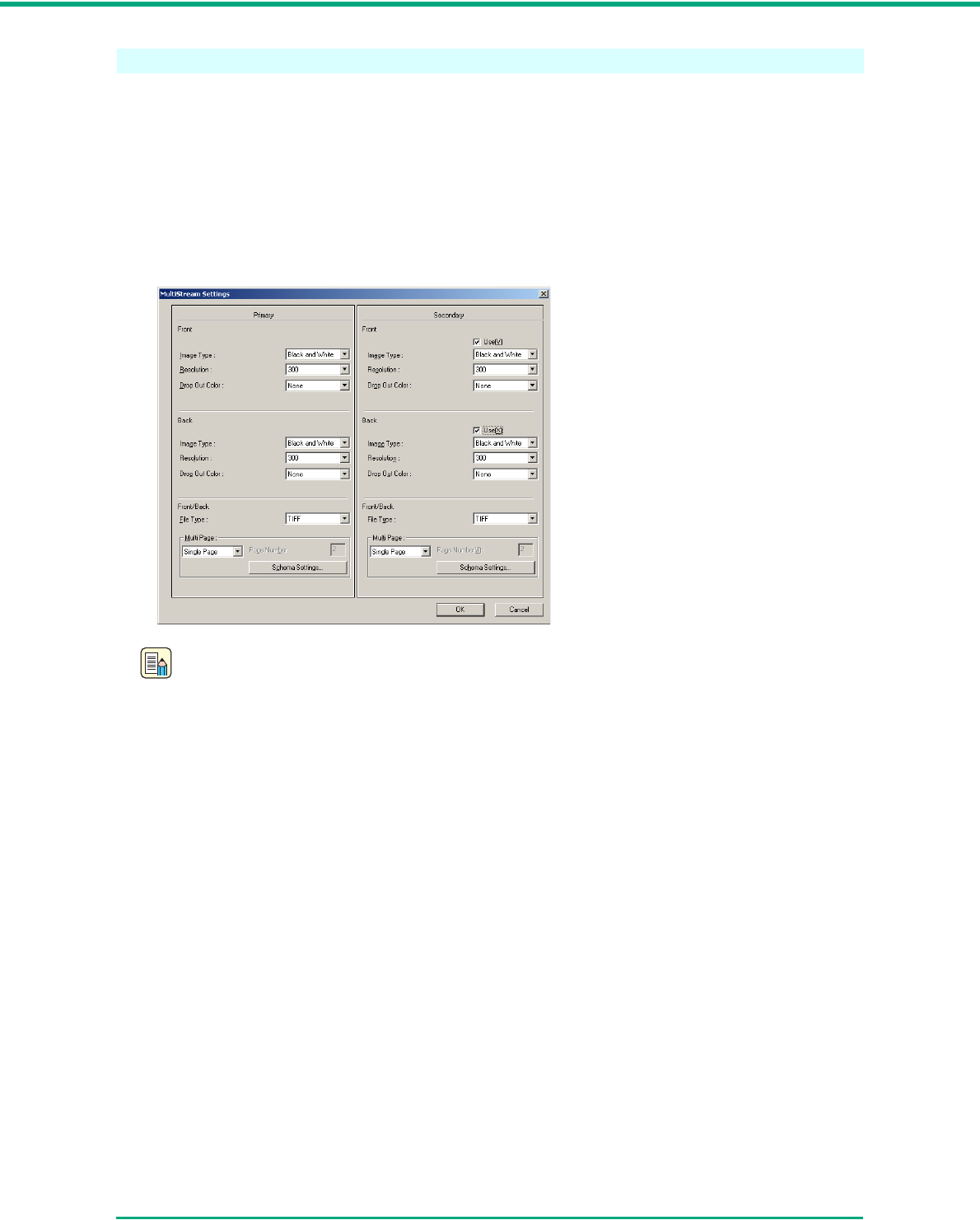
MultiStream Function
If the application that you are using supports the MultiStream function, then it is possible to scan a
document once and simultaneously output two types of images (Primary image and Secondary
image.)
CapturePerfect 3.0 supports the MultiStream function. The following settings are possible.
• You can set the Primary or Secondary image and Front or Back for the Image Type (mode),
Resolution or Drop Out Color.
• You can change the File Type for the Primary image and the Secondary image. However,
you cannot change Front or Back from File Type.
Note
• When using the MultiStream function, “Auto Color Detection,” “Prevent Bleed Through,”
“Prescan,” and “Batch Separation by Patchcode Sheet” cannot be set.
• The MultiStream function is not available when “Auto Color Detection” is selected for the
Mode setting in the ISIS/TWAIN driver.
4-1
Chapter 4
Maintenance
4-1 Regular Maintenance
Clean the scanner on a regular basis as described below to maintain peak scanning quality.
CAUTION
■When cleaning the scanner, turn OFF the power switch and disconnect the power
cord from the power outlet.
■Do not use excessive force when removing or attaching the rollers. Doing so may
damage them.
■Do not use spray type cleaners to clean the scanner. Precision mechanisms, such
as the light source, may get wet, and cause a malfunction.
■Never use paint thinner, alcohol, or other organic solvents to clean the scanner.
Such solvents can damage or discolor the exterior of the scanner, or create a risk
of fire or electrical shock.
Cleaning the Scanner
To clean the exterior of the scanner, dampen a cloth with water or a mild detergent, wring the cloth
out thoroughly, and then wipe the dirt away. Then use a dry, soft cloth to wipe away any moisture.
Cleaning the Feed Path
Dust or paper particles in the document feed opening or inside the scanner can cause lines in
scanned images. Use compressed air to periodically clean dust and paper particles from the
document feed opening and the inside of the scanner. After finishing a large scanning job, turn OFF
the scanner and then clean out any paper particles.
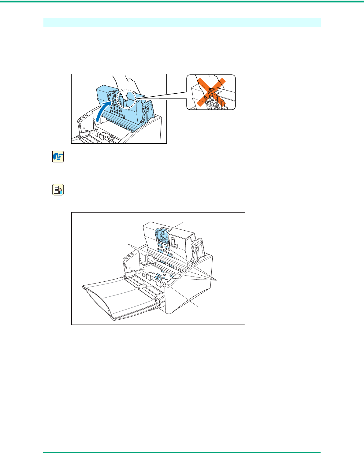
Chapter 4 Maintenance
4-2
Cleaning the Sensor Glass and the Rollers
If scanned images have extraneous marks, or if the scanned documents are dirty, the sensor glass
or rollers inside the scanner may be dirty. Clean them periodically.
1Carefully open the upper unit until it stops.
IMPORTANT
When opening the upper unit, do not grasp the roller unit in the center. Doing so may distort
the rollers and lead to feeding errors.
Note
The location of the sensor glass and various rollers are shown below.
2Use compressed air to keep the interior of the scanner free of dust and paper particles.
Retard Roller
Rollers
Sensor Glasses
Roller Unit
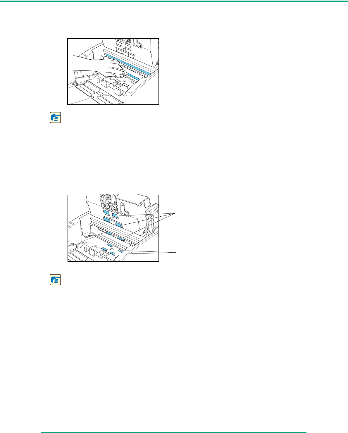
Chapter 4 Maintenance
4-3
3Use a clean dry cloth to wipe dirt off the sensor glass.
Wipe both the top and bottom sensor glasses.
IMPORTANT
Scratches on the sensor glass may cause marks on the images and could cause feeding
errors. If there are scratches on the sensor glass, contact your local authorized Canon dealer
or service representative.
4Dampen a cloth with water, wring it out thoroughly, and then wipe the rollers of the upper unit
while turning them.
Do not try to turn the rollers in the lower part of the scanner. Clean these rollers simply by
wiping the exposed part.
IMPORTANT
• Do not use detergent to clean the rollers, since any detergent remaining on the rollers could
cause a feeding error.
• Do not try to turn the rollers in the lower part of the scanner. Turning these rollers by force
may damage them and lead to feeding errors.
5Remove the roller unit and the retard roller. (See “Removing the Roller Unit,” on p. 4-9, and
“Removing the Retard Roller,” on p. 4-11.)
Clean while turning
Clean only
exposed part
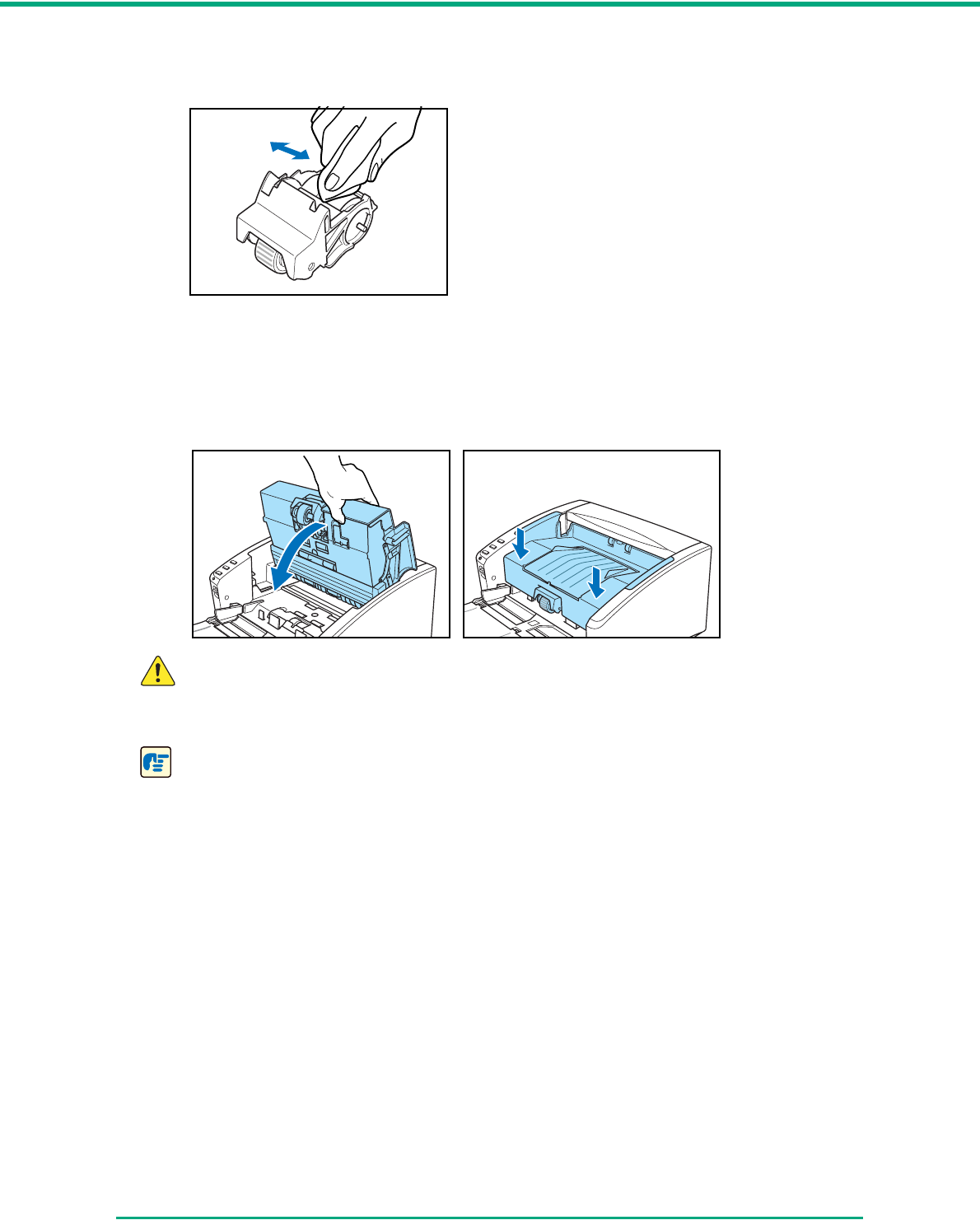
Chapter 4 Maintenance
4-4
6Wipe the removed rollers with a cloth that has been moistened with water and thoroughly
wrung out.
7Attach the rollers that were removed. (See “Attaching the Roller Unit,” on p. 4-10, and
“Attaching the Retard Roller,” on p. 4-12.)
8Make sure that the upper unit is completely closed by pushing on both edges with both hands
until you hear a click.
CAUTION
When closing the upper unit, be careful not to get your fingers caught, as this may
result in personal injury.
IMPORTANT
Do not force the upper unit to close. Doing so may damage the scanner.
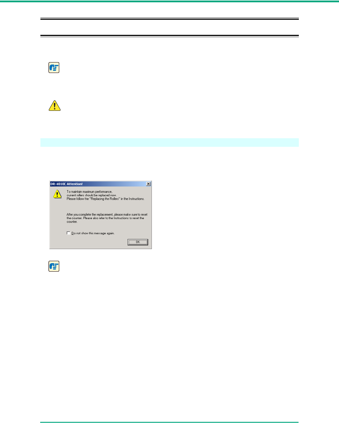
Chapter 4 Maintenance
4-5
4-2 Removing and Attaching the Rollers
To clean or replace the roller unit or retard roller, remove and then attach the parts as described in
each respective section.
IMPORTANT
Feed rollers are consumable parts. When the rollers start to wear out, paper jams and
misfeeds may occur more often. When this happens, purchase an exchange roller kit and
replace the roller unit and the retard roller.
CAUTION
Do not use excessive force when removing or attaching the rollers. Doing so many
damage them.
Roller Replacement Cycle
When the rollers being used have fed more than 250,000 pages, a roller replacement message
appears on the computer. Purchase an exchange roller kit and replace the roller unit and the retard
roller.
IMPORTANT
• If misfeeds happen often, check the rollers for wear, and replace them if necessary before
the message is displayed.
• Be sure to reset the counter after replacing the rollers. (See “Resetting the Counter,” on
p. 4-6.)
• For information about the exchange roller kit (roller unit, retard roller,) contact your local
authorized Canon dealer or service representative.
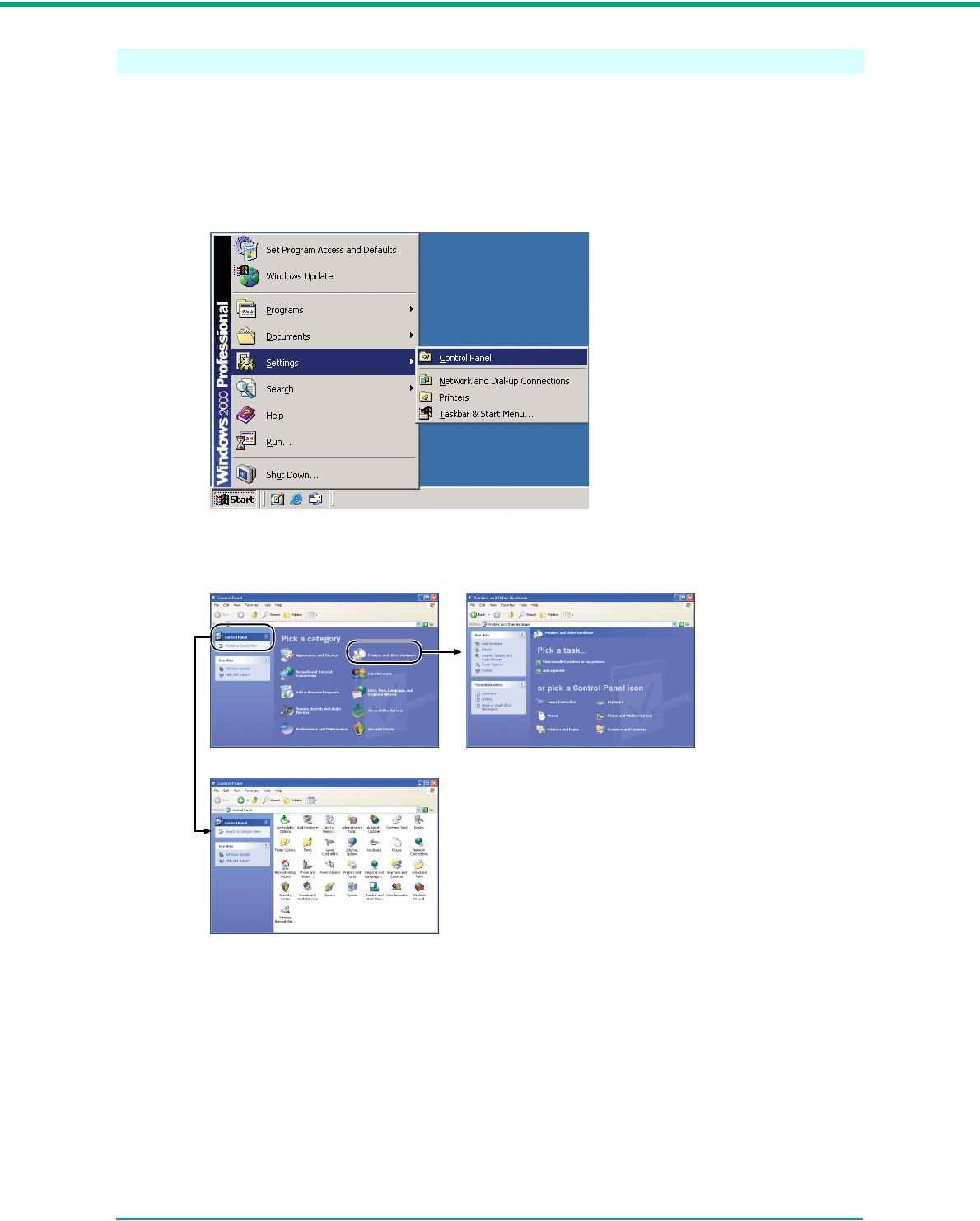
Chapter 4 Maintenance
4-6
Resetting the Counter
After replacing the feed rollers, open the [Counter setup] dialog box and reset the counter.
1Open the [Event settings] dialog box.
1. Click the [Start] button, Æ [Settings] on the [Start] menu Æ click [Control Panel]. (For
Windows XP, click the [Start] button Æ click [Control Panel].)
2. For Windows XP, switch the Control Panel to Classic View, or select [Printers and Other
Hardware] in the working field.
Printers and Other HardwareControl Panel (Category View)
Control Panel (Classic View)
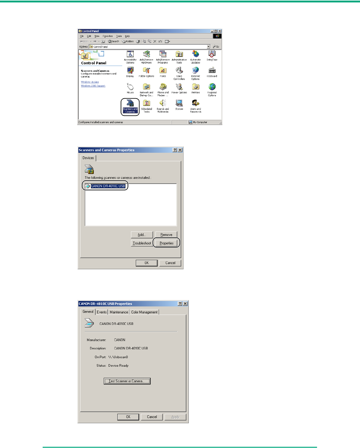
Chapter 4 Maintenance
4-7
3. Double-click [Scanners and Cameras].
4. Select [CANON DR-4010C USB] (or [CANON DR-4010C SCSI],) Æ click [Properties].
[CANON DR-4010C USB Properties] (or [CANON DR-4010C SCSI Properties]) is
displayed.
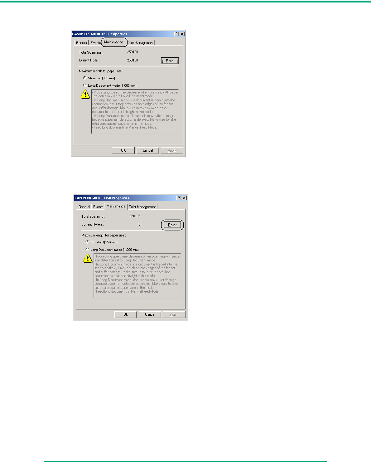
Chapter 4 Maintenance
4-8
2Click the [Maintenance] tab.
3Click the [Reset] button, and then make sure that the counter for the roller being used is set
to 0.
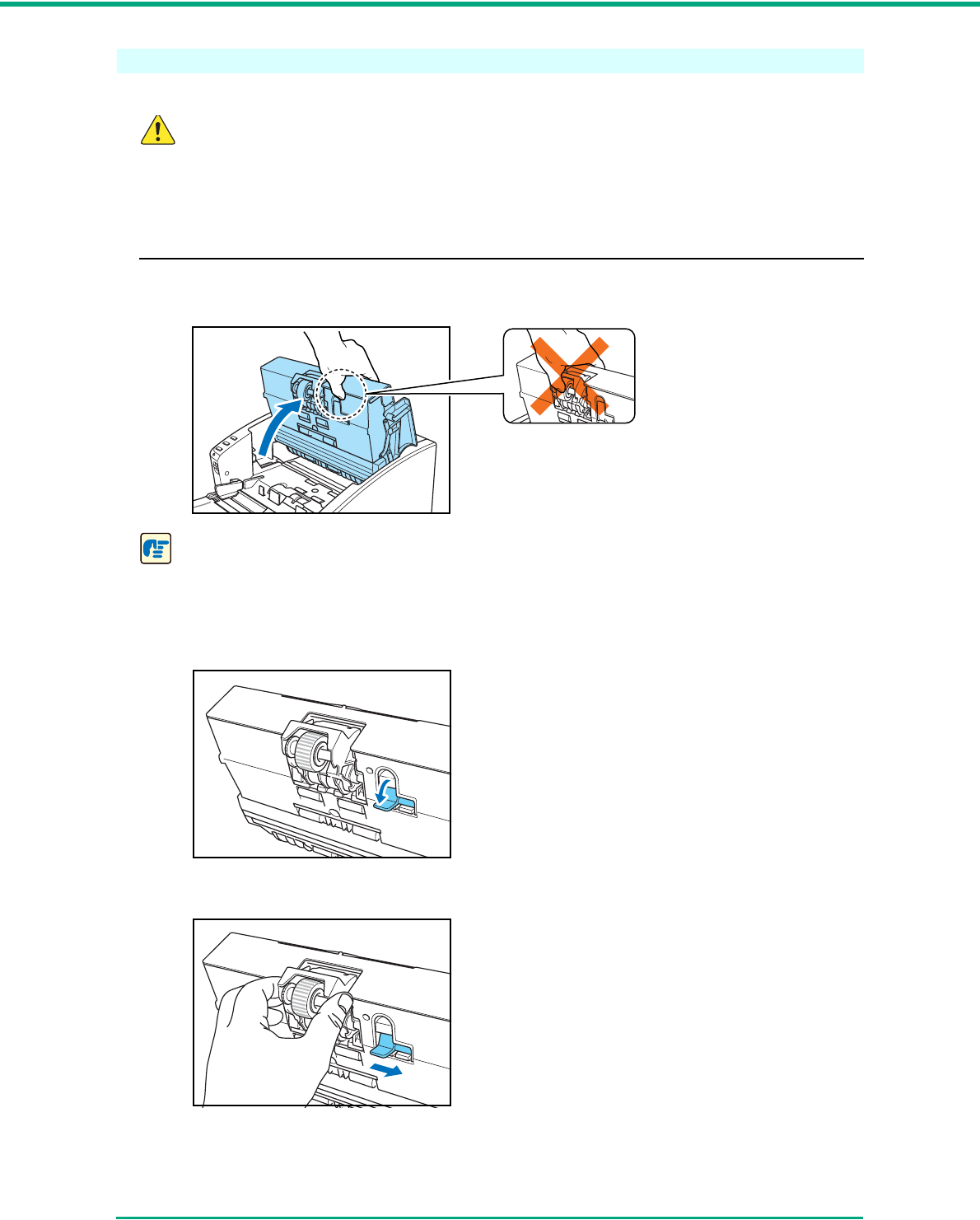
Chapter 4 Maintenance
4-9
Removing/Attaching the Roller Unit
To remove or attach the roller unit, proceed as follows.
CAUTION
Use caution when removing or attaching the roller unit. Using too much force may lead
to damage or personal injury.
Removing the Roller Unit
1Carefully open the upper unit until it stops.
IMPORTANT
When opening the upper unit, do not grasp the roller unit in the center. Doing so may distort
the rollers and lead to feeding errors.
2Push the roller lock lever down.
3While supporting the roller unit with your hand, slide the roller lock lever to the right.
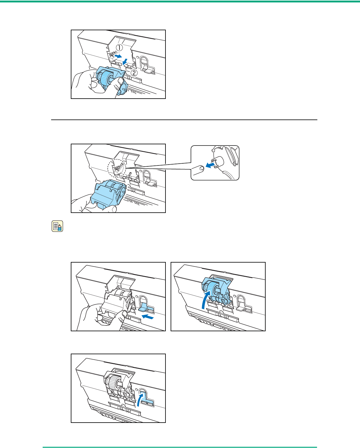
Chapter 4 Maintenance
4-10
4Move the roller unit to the right a and then pull it out b.
Attaching the Roller Unit
1Align the cutout on the roller unit with the shaft pin on the main unit.
Note
If the cutout and pin do not fit, rotate the roller until the parts are properly matched.
2Slide the roller lock lever to the left and raise the roller unit into position.
3Push the roller lock lever up to lock the roller unit.
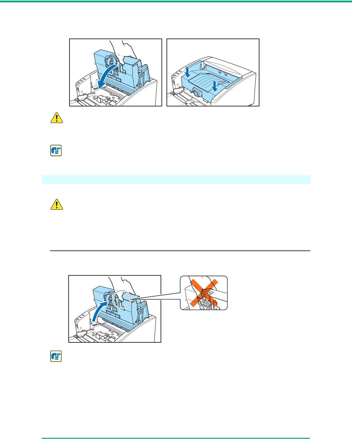
Chapter 4 Maintenance
4-11
4Carefully lower the upper unit. Finally, push the upper unit down with both hands at the sides
until the unit clicks into place. Verify that the upper unit is properly closed.
CAUTION
When closing the upper unit, be careful not to get your fingers caught, as this may
result in personal injury.
IMPORTANT
Do not force the upper unit to close. Doing so may damage the scanner.
Removing and Attaching the Retard Roller
To remove or attach the retard roller, proceed as follows.
CAUTION
Do not use excessive force when removing or attaching the retard roller. Doing so may
damage it.
Removing the Retard Roller
1Hold the upper unit as shown in the diagram, and open it until it stops.
IMPORTANT
When opening the upper unit, do not grasp the roller unit in the center. Doing so may distort
the rollers and lead to a feeding error.
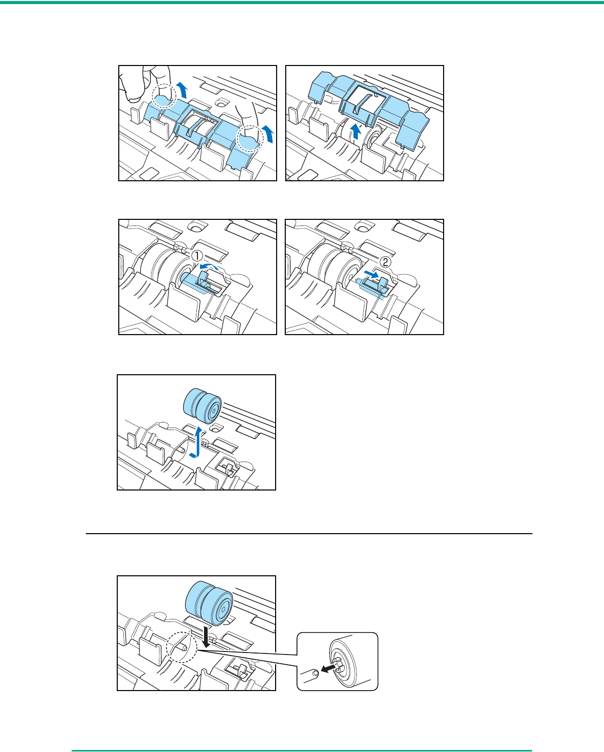
Chapter 4 Maintenance
4-12
2Insert a finger of each hand into the grooves on both ends of the roller cover and remove the
cover.
3Move the roller lock lever down and forward (a,) and then slide it to the right (b.)
4Shift the retard roller to the right to remove it.
Attaching the Retard Roller
1Position the retard roller so the notch in the roller is facing the scanner’s shaft.
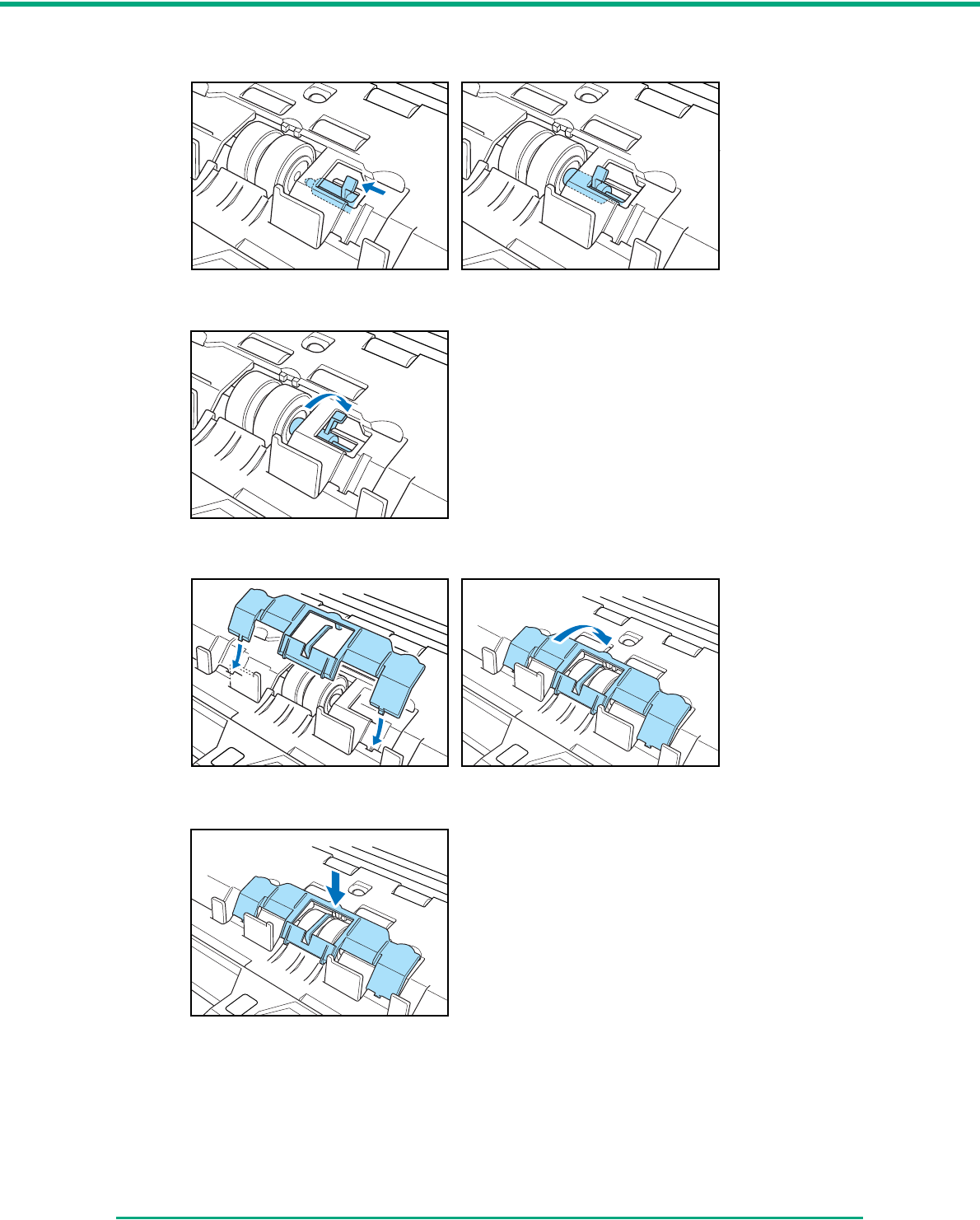
Chapter 4 Maintenance
4-13
2Slide the roller lock lever to the left, and insert it into the retard roller slot.
3Push the roller lock lever towards the back of the scanner to lock the retard roller into place.
4Replace the roller cover.
5Push the center of the roller cover down and make sure that it clicks into place.
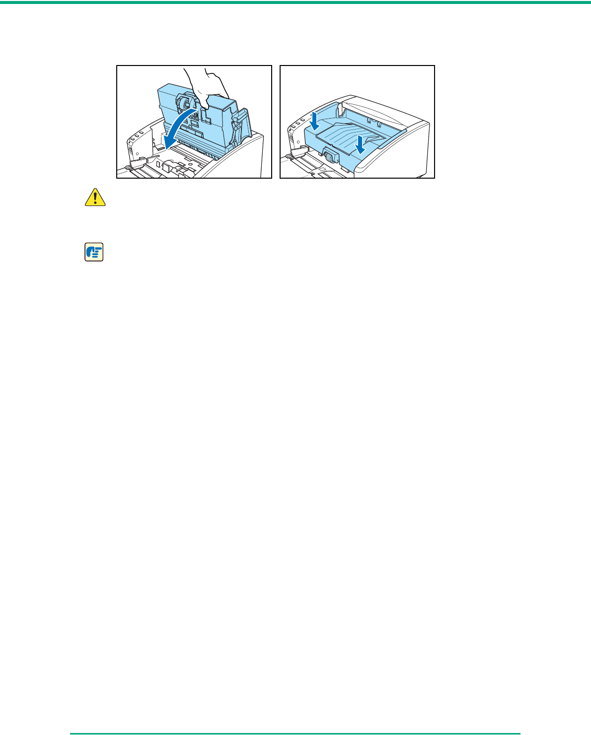
Chapter 4 Maintenance
4-14
6Close the upper unit slowly. Make sure that the upper unit is completely closed by pushing on
both edges with both hands until you hear a click.
CAUTION
When closing the upper unit, be careful not to get your fingers caught, as this may
result in personal injury.
IMPORTANT
Do not force the upper unit to close. Doing so may damage the scanner.

5-1
Chapter 5
Troubleshooting
5-1 Troubleshooting
This section describes the possible problems that might occur during use of the scanner and how to
solve them.
The Scanner Does Not Turn ON ............................................................. P. 5 - 1
The Scanner Is Not Recognized (Connecting via USB).......................... P. 5 - 1
The PC Does Not Recognize the Scanner (Connecting via SCSI) ......... P. 5 - 2
Scanning Is Not Performed ..................................................................... P. 5 - 2
Slow Scanning Speed............................................................................. P. 5 - 3
Documents Do Not Feed Properly .......................................................... P. 5 - 3
Saved Image Files Do Not Open ............................................................ P. 5 - 4
Scanning Results Are Not as Expected .................................................. P. 5 - 4
If, after consulting this section, you still cannot resolve the problem, contact your local authorized
Canon dealer or your service representative.
✘The Scanner Does Not Turn ON
Check the following if the scanner does not turn ON:
• Is the power cord connected correctly?
• Is the power cord inserted into the power outlet?
For details on connecting the power cord, see “2-4 Connecting the Scanner to the Computer,” on
p. 2-11.
✘The Scanner Is Not Recognized (Connecting via USB)
The following are possible causes of the PC failing to recognize the scanner. Check each
possible cause.
Problem The scanner is not correctly connected.
Solution Make sure that the scanner and the computer are correctly connected with the USB
cable. (See p. 2-11.)
Problem The scanner power is switched OFF.
Solution Make sure that the scanner is switched ON. If the scanner is OFF, turn the scanner
ON. (See p. 2-11.)
Problem The scanner does not support your USB interface.
Solution This product is not guaranteed to operate with all types of USB interfaces. Contact
your local authorized Canon dealer or service representative for more information.
(See p. 2-2.)
Problem The scanner does not support the USB cable.
Solution Use the USB cable provided with the scanner.

Chapter 5 Troubleshooting
5-2
Problem The USB hub is not compatible with the scanner.
Solution Remove the USB hub.
✘The PC Does Not Recognize the Scanner (Connecting via SCSI)
The following are possible causes of the PC failing to recognize the scanner. Check each
possible cause.
Problem The scanner is not connected correctly.
Solution Make sure that the scanner and the computer are correctly connected. (See p. 2-12.)
Problem The SCSI card is not correctly installed in the PC.
Solution Refer to the documentation for the SCSI card and the computer. Make sure that the
SCSI card is correctly installed in the computer and that it is enabled properly under
the operating system in use.
Problem The scanner’s SCSI ID is identical to the SCSI ID of another device.
Solution Check the SCSI IDs of all SCSI devices connected to the system and set a unique
SCSI ID for the scanner. (See p. 2-12.)
Problem The terminator is not set correctly.
Solution Shut down both the PC and the scanner, and then turn the scanner ON first, and then
the PC. (See p. 2-12.)
Problem There is a problem with another SCSI device that is connected in the daisy
chain.
Solution Do not use the daisy chain connection configuration. (See p. 2-12.)
Problem The PC was turned ON before the scanner.
Solution Shut down both the PC and the scanner, and then turn the scanner ON first, and then
the PC. (See p. 2-14.)
Problem The scanner is not ON.
Solution Check to see if the scanner is ON. If the scanner is not ON, shut down the PC, then
turn the scanner ON first, and then the PC. (See p. 2-14.)
Problem The SCSI card is not compatible with the scanner.
Solution Use a recommended SCSI card. (See p. 2-2.)
✘Scanning Is Not Performed
Check the following if the scanner does not scan an image even though the scanning operation is
performed:
• Has the application software been installed correctly? Has the application software been set up
correctly?
• Is there a problem in the PC system?

Chapter 5 Troubleshooting
5-3
IMPORTANT
• If documents are not scanned normally even if the scanner setup is OK, a probable cause is
that the scanner driver or application software is not running correctly. Re-install the
scanner driver or application software.
• When system errors result in the scanner not functioning at all, turn OFF the scanner and
wait at least ten seconds before turning it ON again. If the error continues to occur, restart
the computer.
• When scanning continues, make sure that the last document scanned was scanned
correctly.
✘Slow Scanning Speed
The following problems might cause the scanning speed to be slow.
Problem Other applications are running in the background on your PC.
Solution Quit all other applications that are running.
Problem Resident applications, such as anti-virus software, are draining memory
resources.
Solution Quit all resident applications.
Problem Temporary files cannot be created in the TEMP folder, as there is not enough
free space on the hard disk.
Solution Delete unwanted files on the hard disk to increase free space on the hard disk.
Problem The USB port you are using does not support Hi-Speed USB 2.0.
Solution Scanning speeds are lower if your computer’s standard USB interface is not
compatible with Hi-Speed USB 2.0. Use a computer that is equipped with USB that is
compatible with Hi-Speed USB 2.0 as standard. (See “2-2 Installation Requirements,”
on p. 2-2.)
Problem The USB cable does not support Hi-Speed USB 2.0.
Solution Use the USB cable provided with the scanner.
Problem The USB hub does not support Hi-Speed USB 2.0.
Solution Remove the USB hub.
✘Documents Do Not Feed Properly
The following are possible causes of a document failing to feed properly. Check each possible
cause.
Problem Static electricity, etc., is causing the pages of the document to stick together,
and they cannot be separated correctly by the scanner.
Solution Before you place your document, thoroughly fan the stack of papers. (See “3-3
Placing Documents,” on p. 3-5.)

Chapter 5 Troubleshooting
5-4
Problem Attempting to scan a document of a size, thickness, or weight that the scanner
cannot scan.
Solution Check the size, thickness, and weight of the document. For precautions concerning
documents, see “3-1 Documents,” on p. 3-1.
Problem The rollers inside the scanner are dirty or worn.
Solution Clean the rollers, see “4-1 Regular Maintenance,” on p. 4-1. If the rollers are worn,
then they need to be replaced. Contact your local authorized Canon dealer or service
representative to purchase a roller replacement kit.
IMPORTANT
The retard roller and roller unit are consumable components. You need to replace the retard
roller and roller unit when cleaning does not appear to improve performance. Contact your
local authorized Canon dealer or your service representative about purchasing a roller
replacement kit, and then replace the retard roller and the roller unit.
✘Saved Image Files Do Not Open
When image files saved by CapturePerfect 3.0 cannot be opened by other applications, the
probable causes are as follows.
Symptoms A multi-page TIFF file saved in CapturePerfect 3.0 cannot be opened by other
applications.
Problem The application you are using to open the TIFF file does not support multi-page
TIFF files.
Solution Open the file with an application that supports multi-page TIFF files.
Symptoms A TIFF file saved in CapturePerfect 3.0 cannot be opened by other
applications.
Problem If the TIFF file saved in CapturePerfect 3.0 has been compressed, the application
you are using to open the TIFF file does not support the compression type that
was used to save the file in CapturePerfect 3.0.
Solution Set the compression type for the image file to [None] and save the file again in
CapturePerfect 3.0.
✘Scanning Results Are Not as Expected
If there is a problem with the scanning result (e.g., the scanned image is not clear, or the image is
striped or dirty,) the probable causes are incorrect ISIS/ TWAIN driver settings or a problem with
the scanning unit inside the scanner. Scanning results can also become skewed if the ISIS/
TWAIN driver has not been installed correctly, or the application in use does not support ISIS/
TWAIN driver functions.
Symptoms The scanned image is too dark (or faint.)
Problem The [Brightness] setting is not set to an appropriate value.
Solution If the image is dark, set a higher [Brightness] setting, or if the image is faint, set a
lower [Brightness] setting.

Chapter 5 Troubleshooting
5-5
Symptoms Text or images on the rear side of your document appear in the scanned
image.
Problem The [Brightness] setting is too low, or the paper is too thin.
Solution Set a higher [Brightness] setting. If the paper is too thin, make a copy of the
documents and then scan the copy. Alternatively, enable the [Prevent bleed
through/remove background] setting.
Symptoms Double-sided scanning is not possible.
Problem “Scanning Side” is set to [Simplex].
Solution Set “Scanning Side” to [Duplex].
Symptoms A black margin appears around the scanned document.
Problem A document smaller than the preset paper size has been scanned. Or, the loaded
document has shifted out of position.
Solution Set [Page size] to [Auto-detection]. Or, set [Border Removal] to on.
Symptoms The scanned image is skewed.
Problem The document has been fed at an angle. (skew)
Solution Use the document guide adapter to prevent document skew, and set [Deskew] to
on.
Symptoms Lines, smudges, or dirt appear on the scanned image.
Problem The scanning glass or rollers inside the scanner are dirty.
Solution Clean the scanning glass and rollers. (See p. 4-1.)
If lines still appear on the image even after cleaning the scanning glass and rollers,
the scanning glass inside the scanner may be scratched. Contact your local
authorized Canon dealer or service representative.
Symptoms The scanned image is abnormal for certain documents.
Problem Functions such as [Auto-detection], [Deskew], or [Border Removal] were used
when scanning documents containing text or photos up to their edges. (The
scanner cannot accurately process the edges of documents.)
Solution Disable functions such as [Auto-detection], [Deskew], or [Border Removal] when
scanning documents containing text or photos up to their edges.
Symptoms The scanned image is abnormal in some applications.
Problem A function not supported by the application was used.
Solution Some applications do not support functions such as auto-detection of the paper
size. Scanning documents with an application such as this will result in an
abnormal scanned image. Try scanning with auto-detection of the paper size set to
“off.”
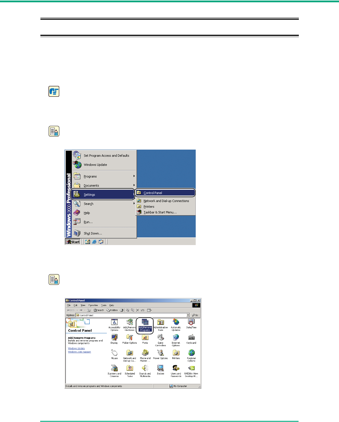
Chapter 5 Troubleshooting
5-6
5-2 Uninstalling Software
If the ISIS/TWAIN driver, and “CapturePerfect 3.0” are not operating normally, follow the procedure
below to uninstall them.
Then, re-install the software from the DR-4010C setup disc. (See “2-3 Installing the Software,” on
p. 2-4.)
IMPORTANT
Be sure to log on as an administrator when using Windows 2000 Professional or Windows XP.
1Click the [Start] button Æ click [Settings] Æ [Control Panel].
Note
For Windows XP, click the [Start] button Æ click [Control Panel].
The [Control Panel] window appears.
2Double-click [Add/Remove Programs].
Note
If you are using Windows XP, double-click the [Add or Remove Programs].
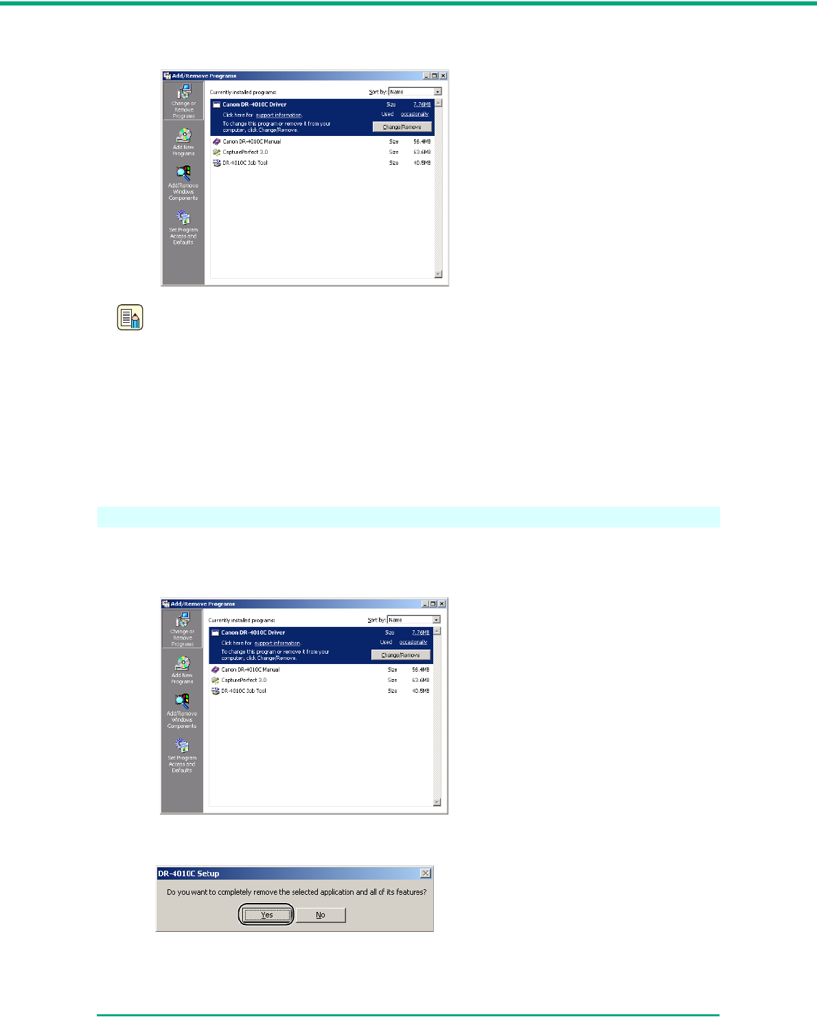
Chapter 5 Troubleshooting
5-7
The [Add/Remove Programs Properties] dialog box appears.
Note
For Windows XP, the [Add or Remove Programs] dialog box appears.
3From the list in the dialog box, select the application you want to delete Æ click [Change/
Remove].
For more information on uninstalling each application, see the following:
“Uninstalling the ISIS/TWAIN Driver,” on p. 5-7
“Uninstalling the Job Registration Tool,” on p. 5-8
“Uninstalling CapturePerfect 3.0,” on p. 5-10.
Uninstalling the ISIS/TWAIN Driver
1From the Programs list in the dialog box, select [Canon DR-4010C Driver] Æ click the
[Change/Remove] button.
2The [Confirm File Deletion] screen appears. Click the [Yes] button.
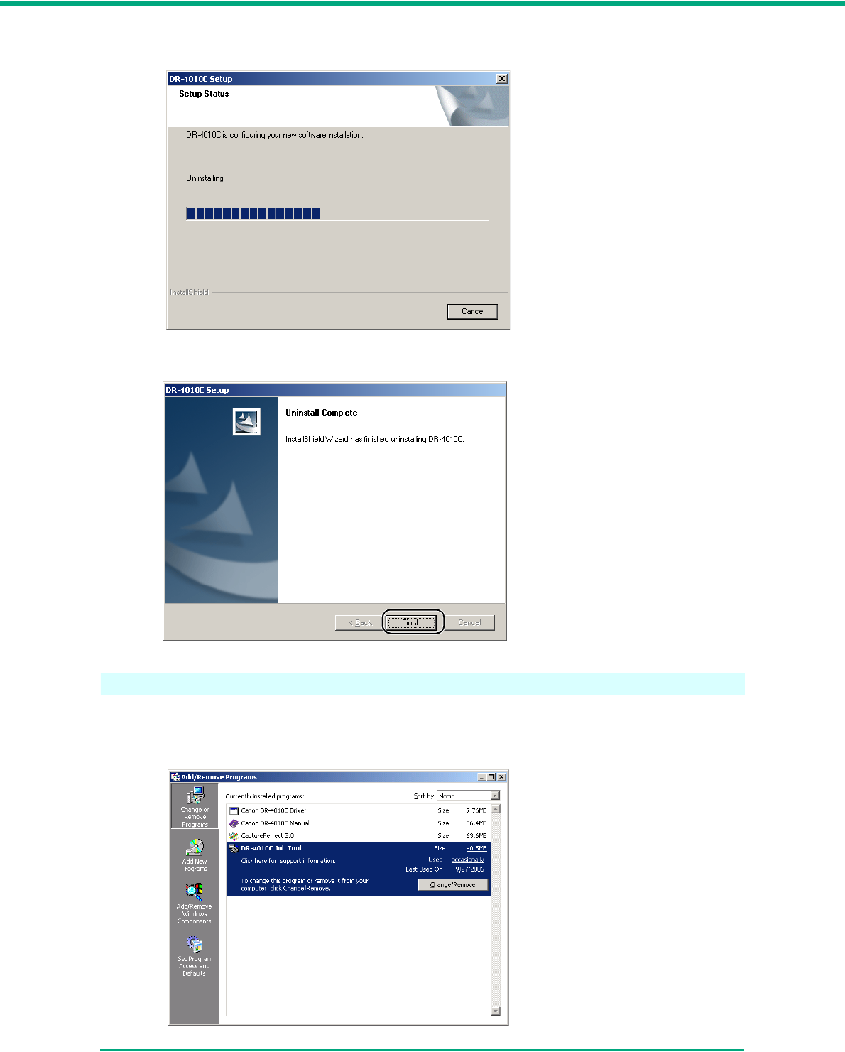
Chapter 5 Troubleshooting
5-8
The uninstall procedure is carried out.
3After uninstall is complete, click the [Finish] button to exit the uninstaller.
Uninstalling the Job Registration Tool
1From the Programs list in the dialog box, select [DR-4010C Job Registration Tool] and click
the [Change/Remove] button.
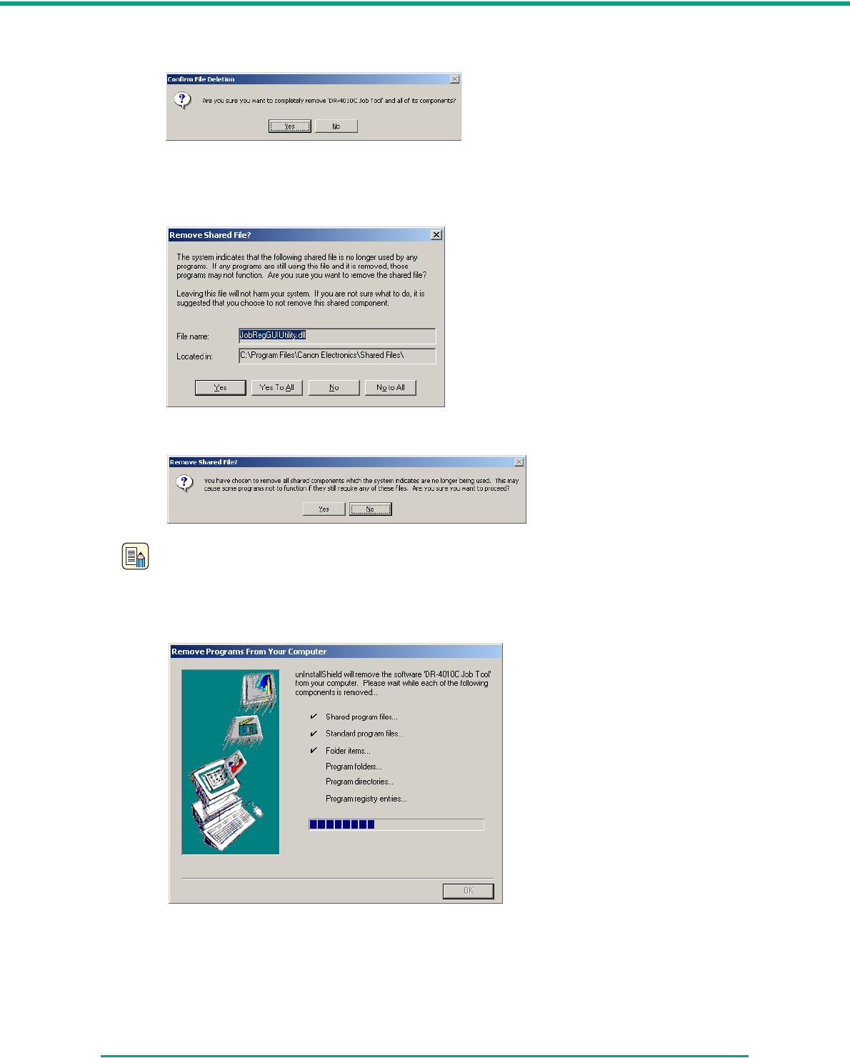
Chapter 5 Troubleshooting
5-9
2The [Confirm File Deletion] screen appears. Click the [Yes] button.
The [Remove Shared File?] dialog box appears.
3Click the [Yes To All] button.
A confirmation message appears.
Note
Under Windows XP, the [Add/Remove Programs] dialog box appears.
4Click the [Yes] button. The uninstall procedure is carried out.
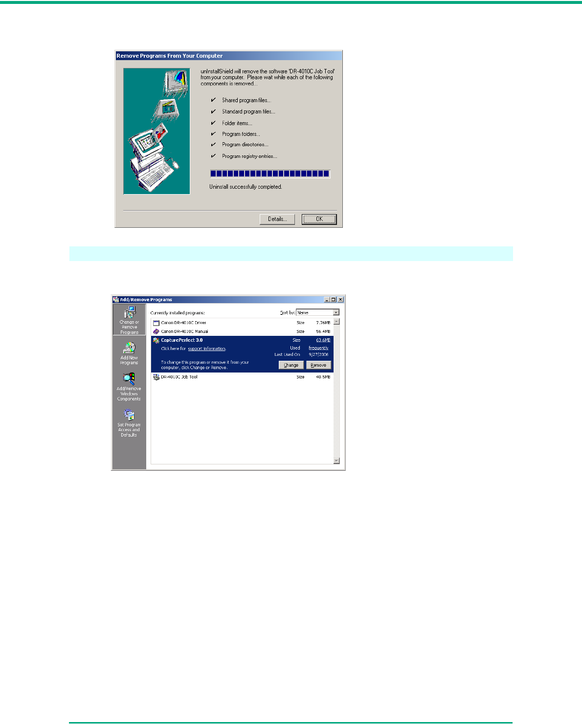
Chapter 5 Troubleshooting
5-10
5After uninstall is complete, click the [OK] button to exit the uninstaller.
Uninstalling CapturePerfect 3.0
1Select [CapturePerfect 3.0] from the list in the dialog box Æ click the [Remove] button.
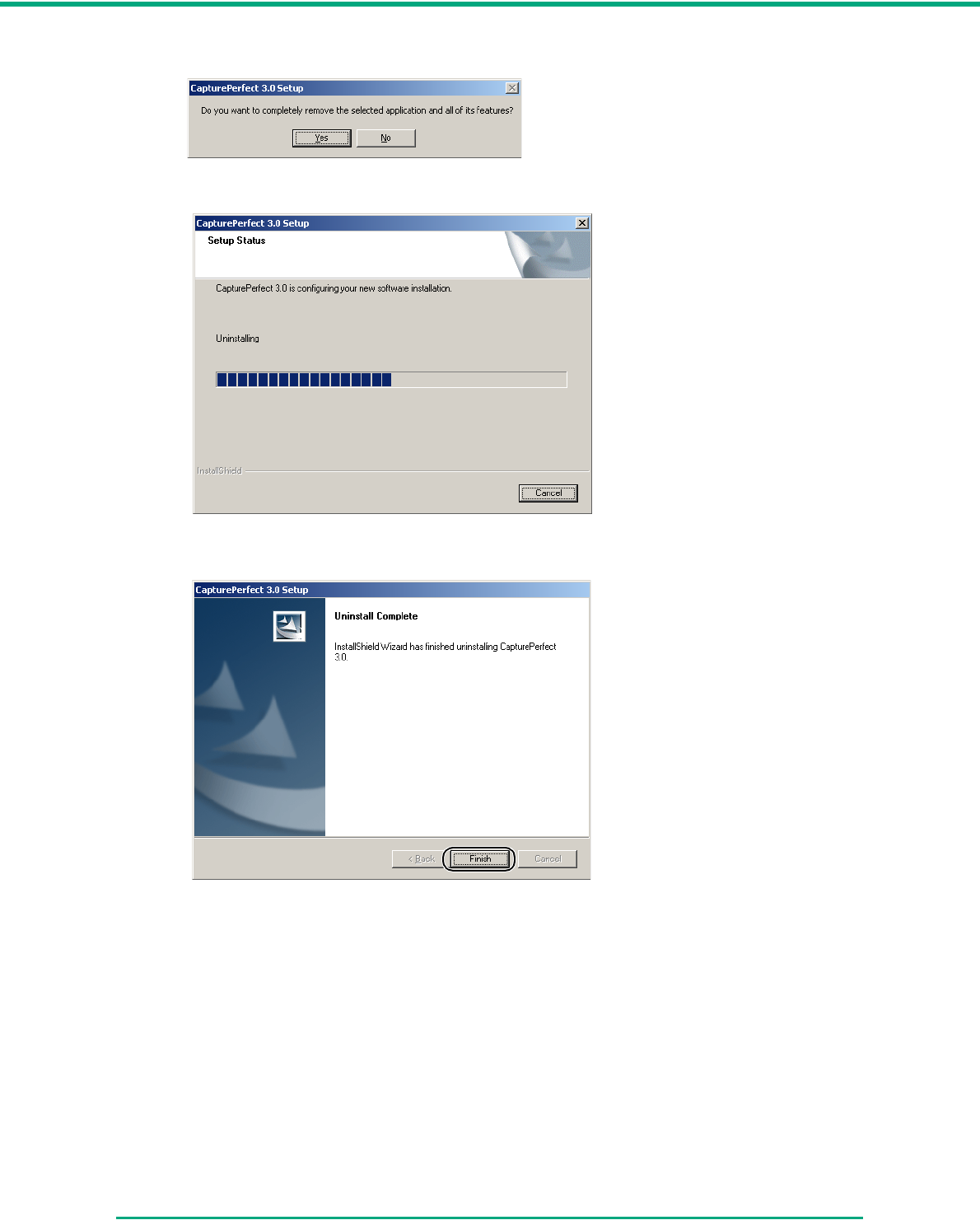
Chapter 5 Troubleshooting
5-11
2The file delete confirmation screen appears. Click the [Yes] button.
Uninstallation starts.
3After uninstallation is complete, click the [Finish] button to exit the uninstaller.

6-1
Chapter 6
Appendix
6-1 Specifications
Specifications
Ty p e
Scanning Document
Specifications
Width:
Length:
Desktop sheetfed scanner
2.08" to 8.6" (53 to 219 mm)
2.75" to 14" (70 to 356 mm)
2.75" to 39.3" (70 to 1000 mm) in Long document mode
Weight: Using the U-Turn Path
(Feed with page
separation mode)
14 to 32 lb bond (0.0024" to 0.0059")
52 to 128 g/m2 (0.06 mm to 0.15 mm)
(Feed with bypass mode) 11 to 40 lb bond (0.0020" to 0.0079")
42 to 157 g/m2 (0.05 mm to 0.2 mm)
Weight: Using the Straight Path
(Feed with page
separation mode)
14 to 32 lb bond (0.0024" to 0.0059")
52 to 128 g/m2 (0.06 mm to 0.15 mm)
(Feed with bypass mode) 11 to 144 lb bond (0.0020" to 0.026")
42 to 546 g/m2 (0.05 mm to 0.66 mm)
Business cards are supported. However, scanning embossed cards is not guaranteed.
Size:
Thickness:
2.12" × 3.37" (53.9 mm × 85.5 mm)
0.03" ± 0.003" (0.76 ± 0.08 mm)
Document Feeding Method Automatic/Manual
Scanning Method Color 3-line contact image sensor
Light Source LED
Effective Scanning Width 236 mm
Scanning Side Simplex/Duplex
Scanning Modes Black and white, Error diffusion, Advanced text enhancement, Advanced
text enhancement II, Highspeed text enhancement, 256-level grayscale, 24
bit color, Auto Color Detection
Scanning Resolution
(Primary Scan Lines ×
Secondary Scan Lines)
100 × 100 dpi, 150 × 150 dpi, 200 × 200 dpi
240 × 240 dpi, 300 × 300 dpi, 400 × 400 dpi, 600 × 600 dpi
Scanning Speed (A4)
Simplex Duplex
Black and White 200 × 200 dpi
300 × 300 dpi
600 × 600 dpi (Speed priority)
600 × 600 dpi (Image quality priority)
42 pages/min.
42 pages/min.
42 pages/min.
20 pages/min.
84 images/min.
84 images/min.
42 images/min.
24 images/min.
256-level Gray 200 × 200 dpi
300 × 300 dpi
600 × 600 dpi (Speed priority)
600 × 600 dpi (Image quality priority)
42 pages/min.
42 pages/min.
42 pages/min.
20 pages/min.
84 images/min.
84 images/min.
42 images/min.
24 images/min.

Chapter 6 Appendix
6-2
• The functions described above can be used if they are supported by the application software.
• Some functions may not be available, depending on the performance of your PC and on your
software.
Due to our ongoing efforts to improve our products, the specifications described above are subject
to change without notice.
Replacement Parts
Exchange roller kit (product code: 1921B001)
Kit to replace the roller unit (pickup roller, feed roller) and retard roller.
• Refer to “Removing and Attaching the Rollers,” on p. 4-5 for information about replacing the rollers.
• Contact your local authorized Canon dealer or service representative for detailed information
about the replacement parts.
Options
Bar code module (product code: 0434B003)
Additional software to allow the ISIS/TWAIN driver to recognize bar codes.
Contact your local authorized Canon dealer or service representative for detailed information about
the Bar code module.
24-bit Color 200 × 200 dpi
300 × 300 dpi
600 × 600 dpi (Speed priority)
600 × 600 dpi (Image quality priority)
42 pages/min.
42 pages/min.
24 pages/min.
20 pages/min.
84 images/min.
84 images/min.
24 images/min.
(not supported)
Amount of paper that can be
stacked in automatic feeder
10 mm stack, maximum
(100 sheets of 20 lb bond (80 g/m2))
Interface Hi-Speed USB 2.0 / SCSI-III
Other Functions Double feed detection, Long Document mode
Dimensions (with trays
closed)
12.5" × 10.9" × 7.3" (W × D × H)
318 mm × 278 mm × 185.5 mm (W × D × H)
Dimensions (with trays open) 12.5" × 21.5" × 7.4" (W × D × H)
318 mm × 545 mm × 187 mm (W × D × H)
Weight Approximately 14.1 lb (6.4 kg)
Power Supply AC 120 V (60 Hz)
AC 220-240 V (50 / 60 Hz)
Power Consumption 120 V model 220-240 V model
Scanning:
Standby:
25 W maximum
Under 3 W
24 W maximum
Under 3 W
Noise Not more than 68 dB
Operating Environment Temperature: 10°C to 32.5°C (50°F to 90.5°F)
Humidity: 20% to 80% RH
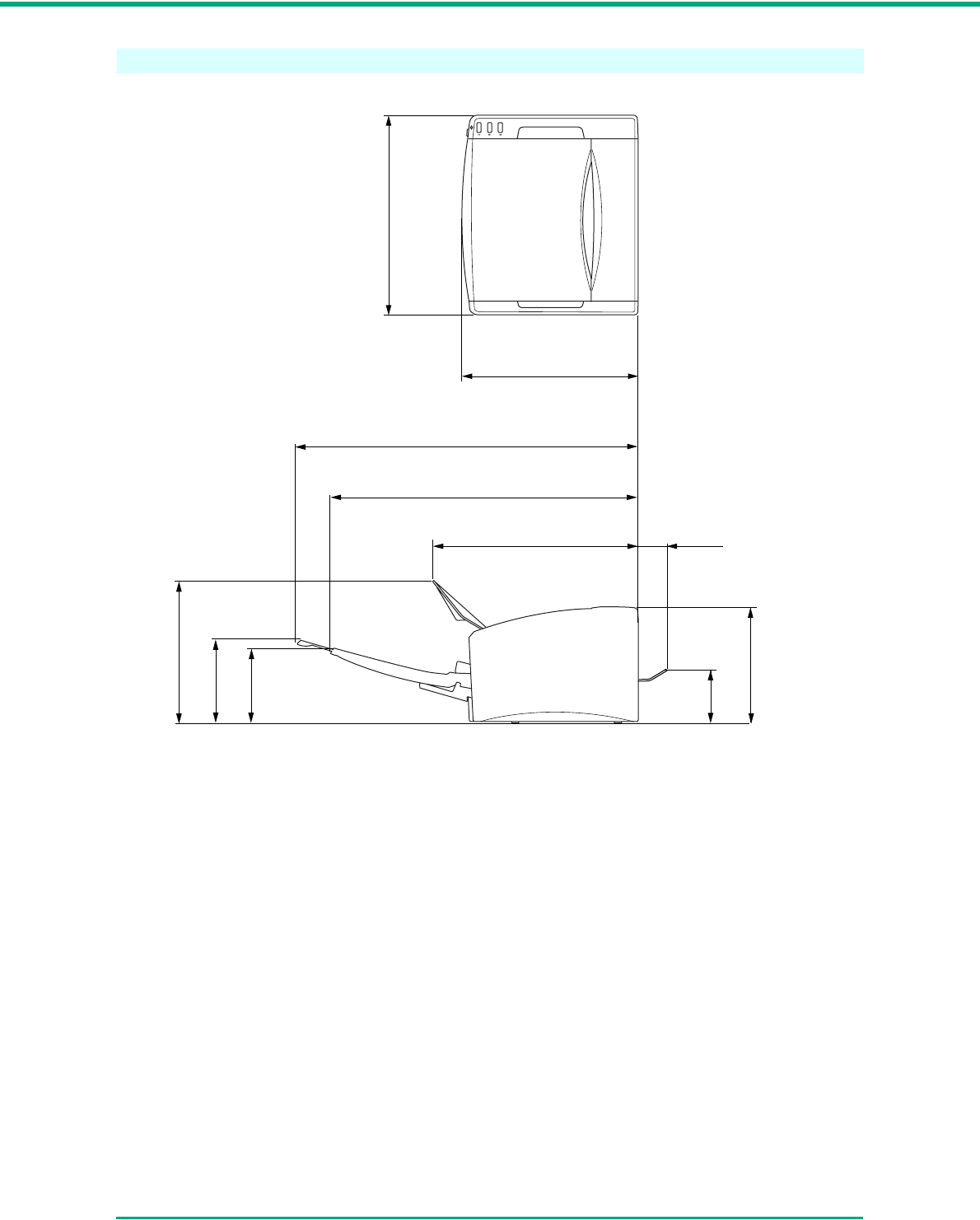
Chapter 6 Appendix
6-3
External Dimensions
21.4" (544 mm)
(Document Feed Tray Extension is open)
12.5" (318 mm)
8.9" (225 mm)
19.3" (491 mm)
(Document Feed Tray is open)
5.2" (131 mm)
10.9" (278 mm)
7.3"
(185.5 mm)
12.9" (330 mm)
(Document Eject Guide is open)
2.0" (51 mm)
(Document Eject Tray 2
is open)
4.7"
(119 mm)
2.9"
(76 mm)

Index
6-4
Index
B
batch separation ............................................................3-23
Bypass Mode ................................................................... 3-7
C
CapturePerfect 3.0 ........................................................3-16
Operation Procedure .............................................3-17
Cleaning
Feed Path ................................................................ 4-1
Rollers .....................................................................4-2
Scanner ................................................................... 4-1
Sensor Glass ........................................................... 4-2
Clearing a Paper Jam ....................................................3-26
Connection
SCSI Connection ...................................................2-12
USB Connection ....................................................2-11
Connection to the Computer ..........................................2-11
D
daisy-chain configuration ...............................................2-12
DIP switches ..................................................................2-12
Disposal ........................................................................... 1-4
document eject configurations ......................................... 3-1
document feed tray ..........................................................3-7
document guides .............................................................3-6
Documents ......................................................................3-1
Double Feed Detection Function ...................................3-30
DR-4010C monitor .........................................................3-11
E
Eject Tray ........................................................................ 3-3
event ..............................................................................3-11
Event settings .................................................................. 4-6
External Dimensions ........................................................6-3
F
Features .......................................................................... 1-5
Folio Scan ......................................................................3-29
H
Handling .......................................................................... 1-3
I
Installation Location .........................................................1-1
Installation Requirements ................................................ 2-2
J
job buttons ....................................................................... 3-9
Job Function .................................................................... 3-9
Scanning With .......................................................3-10
Job Registration Tool .....................................................3-10
L
Launcher ........................................................................3-11
Load limit mark ................................................................ 3-6
Long Document Mode ...................................................3-30
Settings ..................................................................3-31
Long document mode ...................................................... 3-1
M
Moving the Scanner .........................................................1-2
MultiStream Function .....................................................3-34
N
Names of Parts ................................................................ 1-7
O
Options ............................................................................ 6-2
Other Functions ............................................................. 3-29
P
Page Separation Mode ................................................... 3-5
Patchcode Pattern ......................................................... 3-24
Patchcode Sheets ......................................................... 3-23
How to Use ............................................................ 3-24
Placing Documents ......................................................... 3-5
Power .............................................................................. 1-2
power switch ................................................................. 2-14
Power-On ...................................................................... 2-14
R
Regular Maintenance ...................................................... 4-1
Replacement Parts .......................................................... 6-2
Retard Roller ................................................................. 4-11
retard roller ...................................................................... 4-5
Roller Replacement
Replacement Cycle ................................................. 4-5
Resetting the Counter ............................................. 4-6
Roller Unit ....................................................................... 4-9
roller unit .................................................................. 3-8, 4-5
S
Scan Panel .................................................................... 3-21
functions ................................................................ 3-22
Scanner Recognition ..................................................... 2-14
scanning .......................................................................... 3-9
SCSI card ........................................................................ 2-2
SCSI ID ......................................................................... 2-12
Setup
Procedure ................................................................ 2-1
Setup Disc ............................................................... 2-4
Software
Installation ............................................................... 2-4
Uninstalling .............................................................. 5-6
Specifications .................................................................. 6-1
T
terminator ...................................................................... 2-12
Troubleshooting .............................................................. 5-1
Typical Installation ........................................................... 2-5

Document Scanner
User Manual
Software

Contents
ii
Contents
Chapter 7 ISIS/TWAIN Driver Settings ......................................................................7-1
7-1 Before Use .................................................................................................7-1
7-2 ISIS/TWAIN Driver Properties Dialog Box ...............................................7-3
Basic Tab Sheet ..........................................................................................7-4
[Brightness] Tab Sheet ..............................................................................7-13
[Image processing] Tab Sheet...................................................................7-17
[Others] Tab Sheet ....................................................................................7-19
Addon Dialog Box......................................................................................7-24
Chapter 8 Job Registration Tool Settings ................................................................8-1
8-1 Starting the Job Registration Tool...........................................................8-1
8-2 Job Registration Tool Settings Dialog Box.............................................8-2
Job Registration Tool Dialog Box.................................................................8-3
[New/Editing] Dialog Box.............................................................................8-4
Administration Dialog Box ...........................................................................8-8
Chapter 9 Practical Examples....................................................................................9-1
Scanning Both Sides of Pages ....................................................................9-1
Scanning Non-Standard-Size Documents...................................................9-1
Adjusting the Scan Area..............................................................................9-2
Scanning Multiple Documents..................................................................... 9-3
Image Adjustments for Scanning.................................................................9-4
Prescan .......................................................................................................9-7
Preserving Your Settings .............................................................................9-7
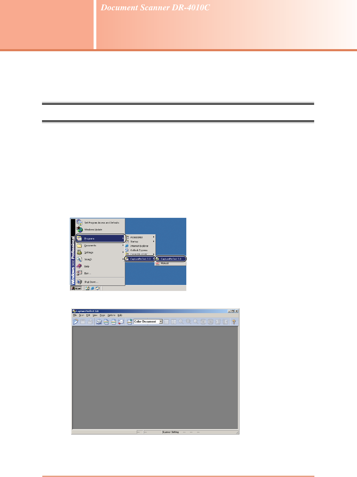
7-1
Chapter 7
ISIS/TWAIN Driver Settings
This chapter describes the dialog boxes of the ISIS and TWAIN drivers. Please read this chapter
and the ISIS/TWAIN driver’s Help before making driver settings.
7-1 Before Use
This scanner can scan documents ranging in size from business cards and checks to A4 size
documents. It can also scan business cards.
To use the DR-4010C with an ISIS/TWAIN-compliant application, the DR-4010C must first be
selected as the scanner to be used.
This section describes how to select the scanner using CapturePerfect 3.0 (an ISIS-compatible
application program.) As the scanner selection procedure depends on the application program being
used, refer to your application’s user’s manual as needed to select the scanner.
1Click the Windows [Start] button, and then click [Programs] ([All Programs] for Windows XP)
Æ [CapturePerfect 3.0] Æ [CapturePerfect 3.0].
CapturePerfect 3.0 starts up.
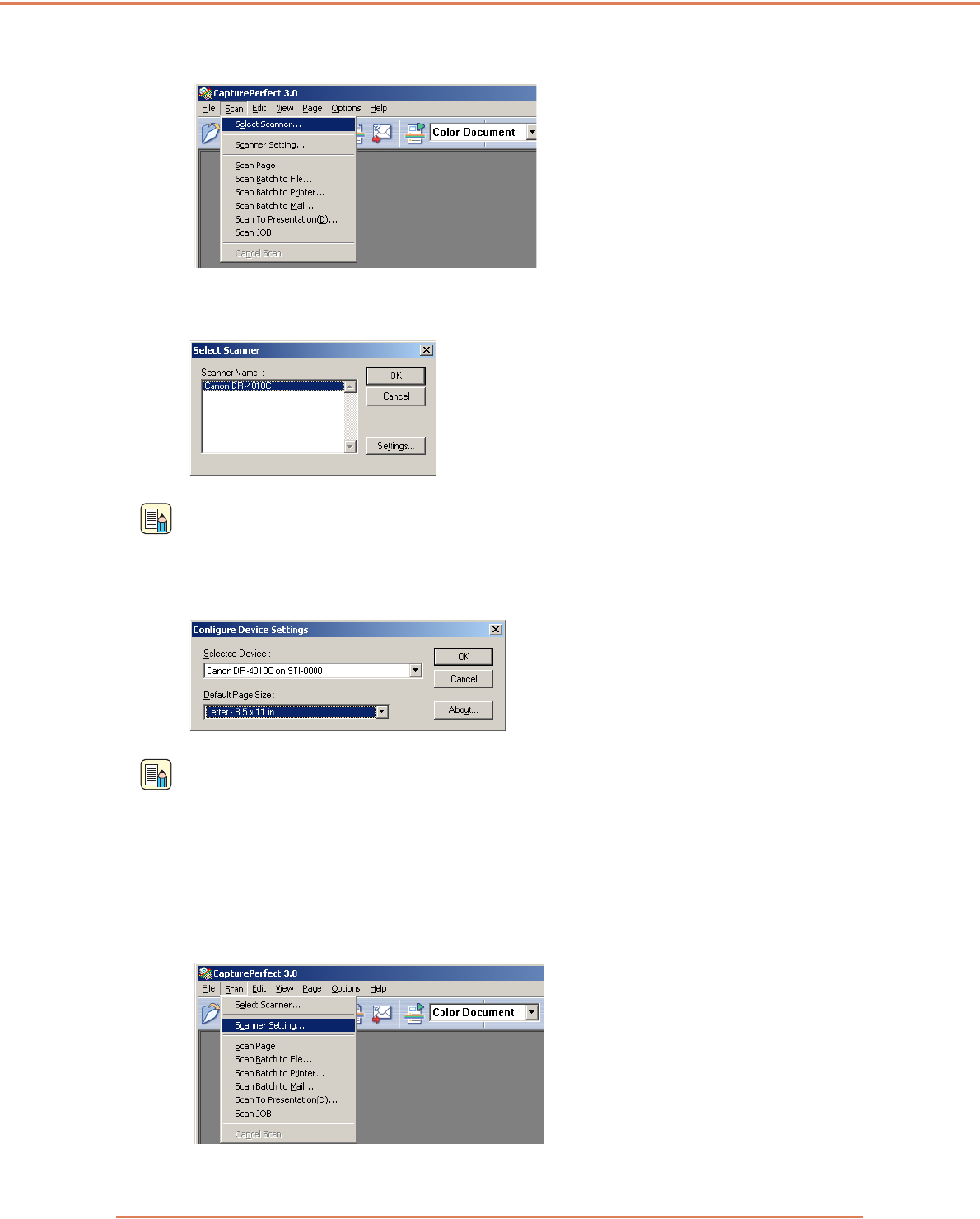
Chapter 7 ISIS/TWAIN Driver Settings
7-2
2On the [Scan] menu, click [Select Scanner].
3Select [Canon DR-4010C] Æ click the [OK] button.
Note
If [Canon DR-4010C] is not displayed in the list of scanners, re-install the ISIS/TWAIN driver.
4Click the [Settings] button to set a default page size.
Note
• Clicking the [Default] button in the ISIS driver Properties dialog box causes that setting to be
applied here.
• With the TWAIN driver, the default size is A4 and cannot be changed.
5Click [OK] to finish scanner selection.
6On the [Scan] menu, click [Scanner Setting].
The Properties dialog box for the ISIS driver opens.
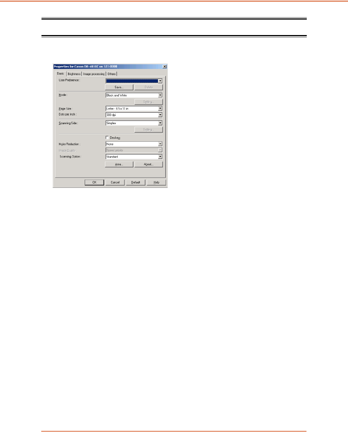
Chapter 7 ISIS/TWAIN Driver Settings
7-3
7-2 ISIS/TWAIN Driver Properties Dialog Box
The ISIS/TWAIN driver properties dialog box consists of four tabs: Basic, Brightness, Image
processing and Others. See the description of each tab sheet for details.
[OK] Button
Applies settings and closes the dialog box.
[Scan] Button (TWAIN driver only)
To control scanning from the properties dialog box when using a TWAIN-compatible application
program, the [Scan] button is displayed instead of the [OK] button to scan with the current settings.
[Cancel] Button
Rejects changes to settings and closes the dialog box.
[Default] Button
Returns the settings to their default state.
[Help] Button
Displays help for the open tab sheet and dialog box.
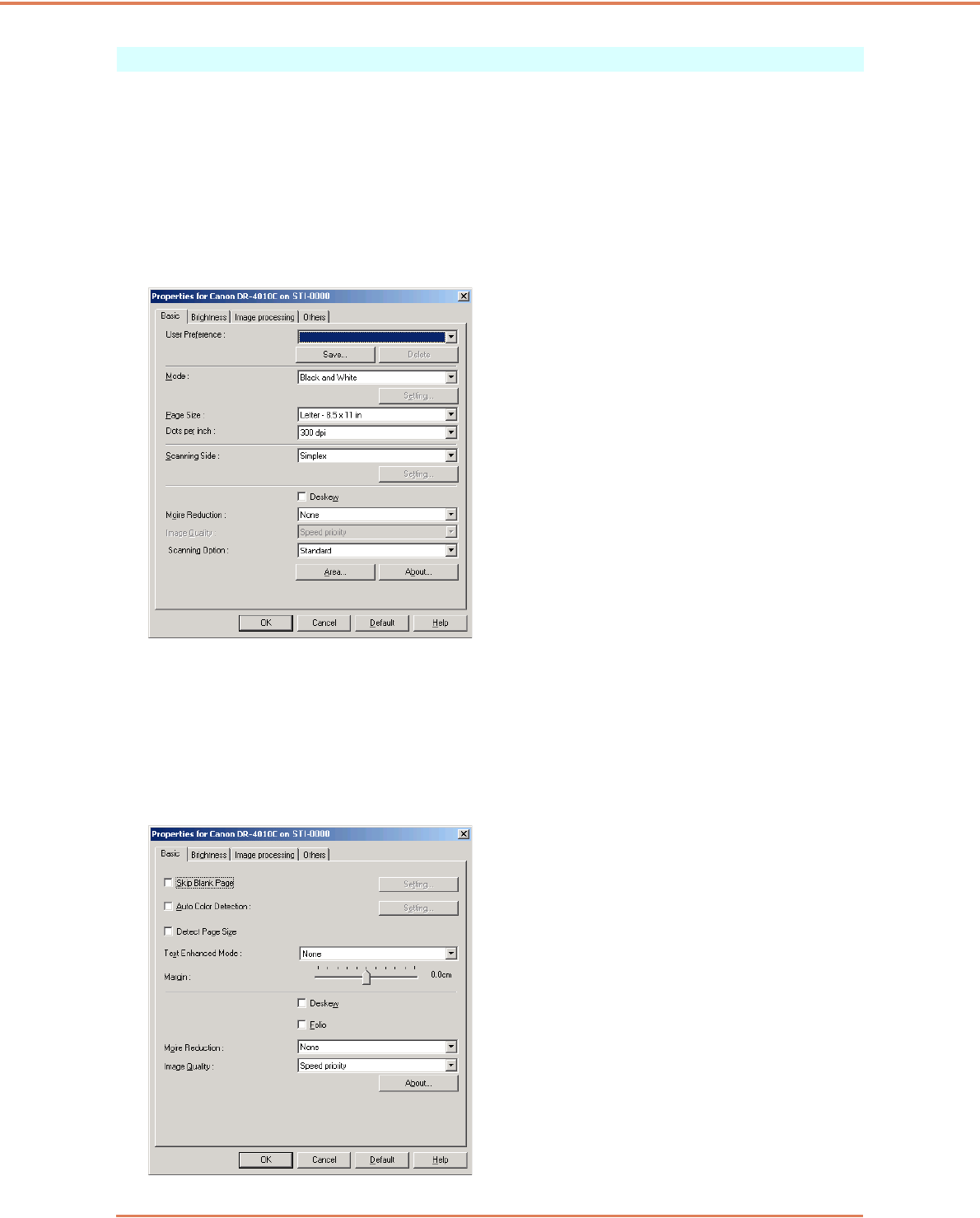
Chapter 7 ISIS/TWAIN Driver Settings
7-4
Basic Tab Sheet
This [Basic] tab sheet is displayed when the driver is called directly and not from another settings
dialog box. The driver is called directly when using applications that do not have their own scanner
setting or scanning dialog boxes, such as CapturePerfect and Job Registration Tool.
Basic Tab Sheet (ISIS/TWAIN driver)
This [Basic] tab sheet is displayed when the driver is called directly and not from another settings
dialog box. The driver is called directly when using applications that do not have their own scanner
setting or scanning dialog boxes, such as CapturePerfect and Job Registration Tool.
☞“Scanning Option” does not appear on the ISIS driver.
[Basic] Tab Sheet Extended Version (ISIS driver only)
This [Basic] tab sheet is displayed when the DR-4010C ISIS Driver is called from a scanner setting
or scanning dialog box belonging to an ISIS-compatible application program.
This [Basic] tab sheet provides settings for DR-4010C functions that are not supported in the dialog
box belonging to the application program.
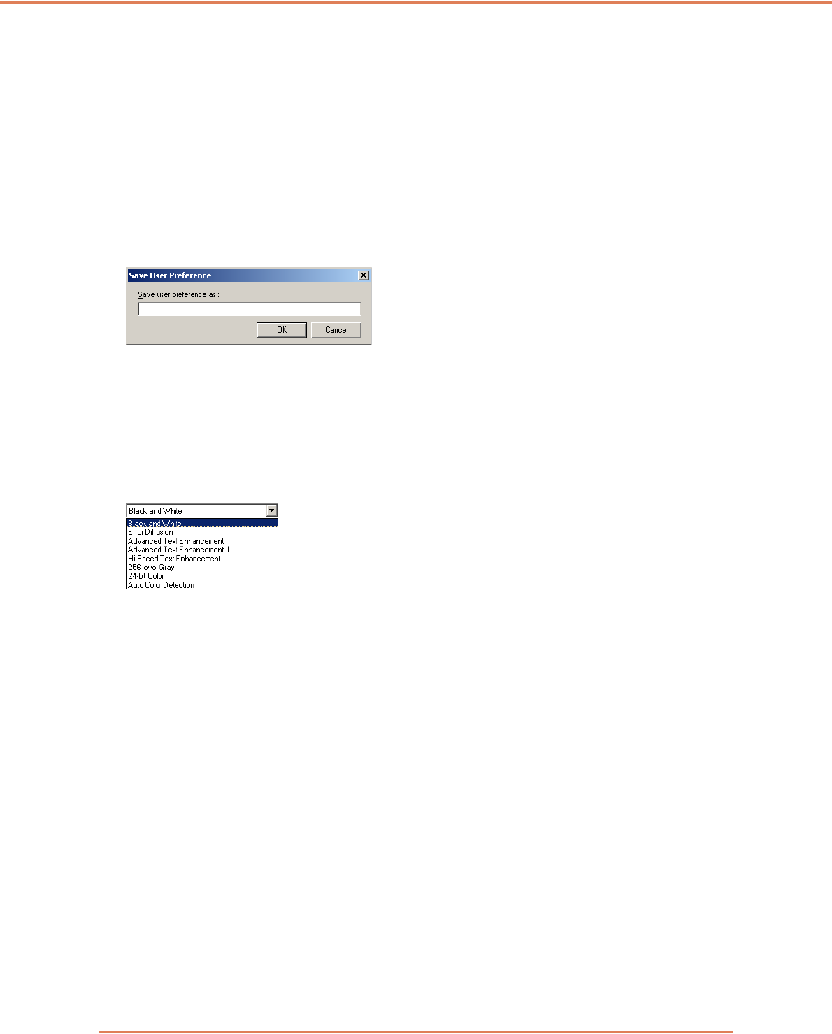
Chapter 7 ISIS/TWAIN Driver Settings
7-5
☞Refer to the descriptions of the following function for details about “Skip Blank Page,” “Auto Color
Detection,” “Detect Page Size,” “Text Enhanced Enhancement Mode” and “Margin.”
• Skip Blank Page Æ [Scanning Side]
• Auto Color Detection Æ [Mode]
•[Detect Page Size] Æ [Page Size]
• [Text Enhanced Mode] Æ [Mode]
• Margin Æ Scan Area Dialog Box
• Folio Æ [Scanning Side]
User Preferences
Click [Save] to open the [Save User Preference] dialog box.
The [Save User Preference] dialog box saves the current settings under an assigned name.
You can select the name of a saved set of user preferences in the list box to load those settings into
each tab sheet.
☞ Assigned names can consist of up to 32 characters (or 16 double-byte characters.)
Mode
Select the mode for scanned images.
☞Some functionality is limited depending on the mode setting. (See “Mode-Dependent Function
Limitations,” on p. 7-7.)
☞The Text Enhancement modes are good for scanning documents with a background color or
design behind text, by removing or processing the surrounding background to enhance the text for
easy reading.
☞Three text enhancement modes are provided to suit different background types. Select the mode
that seems to best suit your document. We recommend confirming an image by prescanning the
first page.
[Black and White]
Use this mode to scan text and line drawing documents as black and while (binary) images.
[Error Diffusion]
Use this mode to scan documents containing photos as black and white (binary) images.
[Advanced Text Enhancement]
Use this mode to scan documents with a dark or non-uniform (pattern) background.
☞ If the background is uniform it is removed where it surrounds the text.
☞ If the background is non-uniform, such a pattern, it is processed to enhance text readability.
[Advanced Text Enhancement II]
Use this mode to scan documents with a light uniform background and low-contrast text.
☞The background in tight spaces around text may not be removed.

Chapter 7 ISIS/TWAIN Driver Settings
7-6
☞Documents with low-contrast text can be made more readable by adjusting Contrast on the
[Brightness] tab sheet.
☞ If the background is non-uniform, such a pattern, the background remains visible in the image,
and text may be hard to read.
[High-Speed Text Enhancement]
This mode optimizes processing speed by performing background processing within the scanner,
and is good for scanning documents with light background and dark text.
☞If the text and background in a document have nearly the same density, the text may be hard to
read.
☞Areas with uniform background may appear as non-uniform white in the image.
☞Because background processing is performed within the scanner, scanned images are more
susceptible to lines appearing due to dirt on the scanning table glass. In cases where this may be
a problem, try scanning again after cleaning the scanner glass, or select one of the [Advanced
Text Enhancement] or [Advanced Text Enhancement II] modes instead.
[256-level Gray]
Scans documents such as photos as 256-level grayscale images.
[24-bit Color]
Scans documents such as color photos as full-color images.
[Auto Color Detection]
Whether a document is black and white or color is detected before the scanned image is saved.
☞When [Auto Color Detection] is enabled, the [Setting] button is enabled for opening the [Auto
Color Detection] dialog box, where you can make settings affecting how color documents are
judged, and select which scanning mode to use for black and white.
☞Depending on the application program, operation may become unstable when [Auto Color
Detection] is enabled. In that case, [Auto Color Detection] should be disabled.
☞When using an application that supports the MultiStream function (such as CapturePerfect), if
[Auto Color Detection] is selected, the MultiStream function is disabled.
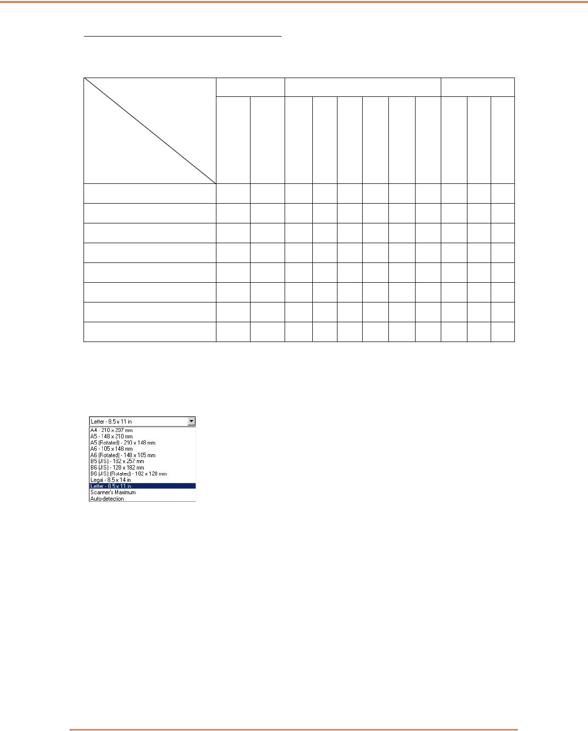
Chapter 7 ISIS/TWAIN Driver Settings
7-7
Mode-Dependent Function Limitations
The following tab sheet functions are partially disabled according to the selected mode. Refer to
“[Brightness] Tab Sheet,” on p. 7-13 for the [Brightness] tab sheet settings.
✓: Available for setting
— : Not available for setting
Page Size
Select the page size of the document to be scanned.
☞Select [Auto-detection] to scan the following kinds of documents.
• Documents of undetermined size
• Documents including mixed page sizes
• When using the Long document mode (See “Long Document Mode,” on p. 3-30.)
☞When [Auto-detection] is selected, area settings in the Scan Area dialog box are disabled.
☞The [Auto-detection] process may malfunction in the following situations. If this occurs, select a
standard size such as [A4] or [Letter], or click the [Area] button to create a custom page size. (See
“[Scan Area] Dialog Box,” on p. 7-11.)
• When scanning a page with a dark area at the left or right edge
• When scanning a glossy or reflective document
• When the brightness setting is incorrect
• When Custom setting is selected in the Gamma Settings dialog box
☞Depending on the application program, operation may become unstable when [Auto-detection] is
enabled. In that case, [Auto-detection] should be disabled.
Tab sheet
Scanning mode
Basic Image processing Others
Deskew
Moire Reduction
Edge enphasis
Erase Dot
Border Removal
Prevent Bleed Through /
Remove Background
Reverse Image
(TWAIN driver)
Color drop-out
JPEG Transfer
Batch Separation
Prescan
Black and White ✓✓✓✓✓✓✓✓—✓✓
Error Diffusion ✓✓✓—✓✓ ✓✓—✓✓
Advanced Text Enhancement ✓✓✓✓✓—✓✓—✓✓
Advanced Text Enhancement II ✓✓—✓✓—✓✓—✓✓
High-Speed Text Enhancement ———✓—— ✓✓—✓✓
256-level Gray ✓✓✓—✓✓—✓✓✓✓
24-bit Color ✓✓✓—✓✓——✓✓✓
Auto Color Detection ✓✓✓✓✓———✓——
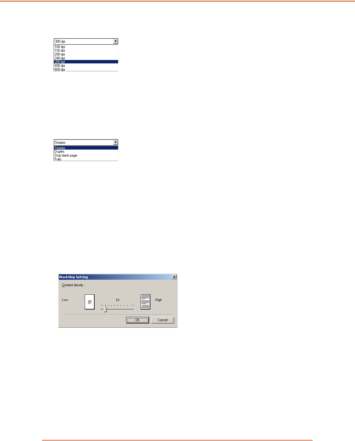
Chapter 7 ISIS/TWAIN Driver Settings
7-8
Dots per inch
Select the scanning resolution.
☞Higher resolutions provide clearer images, but produce larger files.
☞When the selected resolution is 300 dpi or less, the [Moire Reduction] setting is enabled to allow
reduction of Moire patterns in scanned images.
☞When the selected resolution is 400 or 600 dpi, the [Image Quality] setting is enabled.
Scanning Side
Select which page side(s) to scan.
[Simplex]
Scan only the front (top) side of documents loaded at the feeder inlet.
[Duplex]
Scan both sides of documents.
[Skip Blank Page]
As each document page is scanned, its scanned image is judged as to whether it is blank, and if so,
the image is not saved.
☞Selecting [Skip Blank Page] enables the [Setting] button, which opens the [Blank Skip Setting]
dialog box.
☞Adjust the [Content density] setting in the [Blank Skip Setting] dialog box if blank pages are not
skipped, or if non-blank pages are skipped.
The Content density should be adjusted according to document content, so that only blank pages
are skipped: increase the setting if they are not skipped, and decrease the setting if non-blank
pages are skipped.
☞The Skip Blank Pages function may not work properly if the [Custom] setting is enabled in the
Gamma Settings dialog box.
☞When the [Scan Single Page] feeding option is selected in the [Others] tab sheet of the TWAIN
driver, the [Simplex] scanning side setting is selected automatically.
☞If the application program provides its own simplex/duplex scanning side setting, select Simplex in
this dialog box.
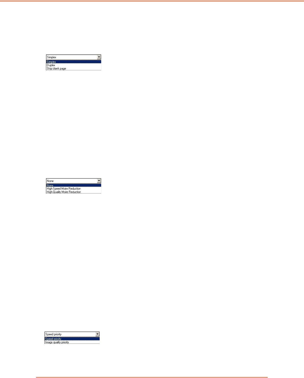
Chapter 7 ISIS/TWAIN Driver Settings
7-9
[Folio]
Documents that are normally folded in half are scanned on both sides and composed into one
image. (See “Folio Scan,” on p. 3-29.)
☞[Folio] is not displayed if [Patchcode] is selected as the Batch Separation setting on the [Others]
tab sheet.
[Deskew] Check Box
The Deskew function detects slanted document pages and straightens the scanned images.
☞The Deskew function does not work properly in the following situations. Disable Deskew in these
cases.
• When scanning a page with a dark area near the edge
• When scanning a glossy or reflective document
• When the brightness setting is incorrect
• When Custom setting is selected in the Gamma Settings dialog box
☞Note that in other cases, depending on the document, the slant of the image may not be corrected
properly or part of the image may be omitted.
Moire Reduction
When 300 dpi or lower resolution is selected, you can enable Moire reduction if Moire patterns
appear in scanned images.
[None]
No Moire processing is performed.
[High Speed Moire Reduction]
This mode gives priority to scanning speed, and generates images with the specified resolution from
images scanned at 300 dpi. When 300 dpi resolution is selected, [High-Speed Moire Reduction] is
not displayed.
[High Quality Moire Reduction]
This mode gives priority to image quality, and generates images with the specified resolution from
images scanned at 600 dpi.
Although image quality is high, scanning is slow.
When [High Quality Moire Reduction] is selected while Page Size is set to [Auto-detection], Mode is
set to [24-bit Color], and Scanning Side is set to [Duplex] all at the same time, a portion of the
document may not be scanned due to insufficient memory on the scanner. If this occurs, lower the
image quality by selecting [Speed priority], or change the Scanning Side setting to [Simplex].
Image Quality
When 400 or 600 dpi resolution is selected, you can enable this and select either [Speed Priority] or
[Image Quality Priority Image].
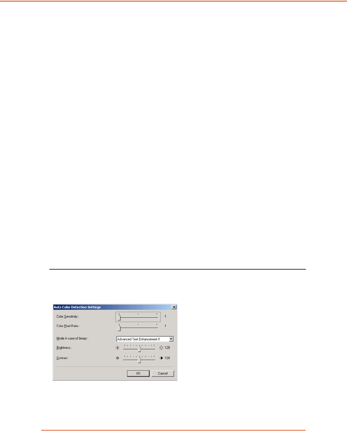
Chapter 7 ISIS/TWAIN Driver Settings
7-10
[Speed Priority]
This mode gives priority to scanning speed, and generates 400 or 600 dpi images from images
scanned at 300 dpi.
Although scanning speed is fast, image quality is slightly reduced.
[Image Quality Priority]
This mode gives priority to image quality, and scans at 600 dpi.
When 400 dpi resolution is selected, 400 dpi images are generated from images scanned at 600 dpi.
☞Scanning with 24-bit Color is disabled when [Image Quality Priority] is selected. Also, an error
may be displayed with some combinations with other settings, in which case [Speed Priority]
should be selected, or other settings changed.
[Scan Options] (TWAIN driver only)
Specify operation when scanning continuously with a TWAIN-compatible application.
[Standard image]
Eject a scanned page before scanning the next page.
[Scan Ahead]
Scan pages continuously, so scanning speed is faster than [Standard image].
[Scan Single Page]
The [Scanning Side] setting on the [Basic] tab sheet becomes [Simplex], and one page is scanned.
When [High Quality Moire Reduction] is selected while Page Size is set to [Auto-detection], Mode is
set to [24-bit Color], and Scanning Side is set to [Duplex] all at the same time, a portion of the
document may not be scanned due to insufficient memory on the scanner. If this occurs, lower the
image quality by selecting [Speed priority], or change the Scanning Side setting to [Simplex].
[Area] Button
Open the [Scan Area] dialog box to specify the area to scan. (See “[Scan Area] Dialog Box,” on p. 7-
11.)
The [Area] button is not displayed if the application program provides its own function to specify scan
area.
[Auto Color Detection Settings] Dialog Box
This dialog box appears when you select [Auto Color Detection], where you can make settings for
detecting whether scanned images are color or black and white, and select the mode to use when
an image is detected as black and white.
Color Sensitivity
Adjusts sensitivity to colors in a document.
Color Pixel Ratio
Select from three color pixel ratio settings.
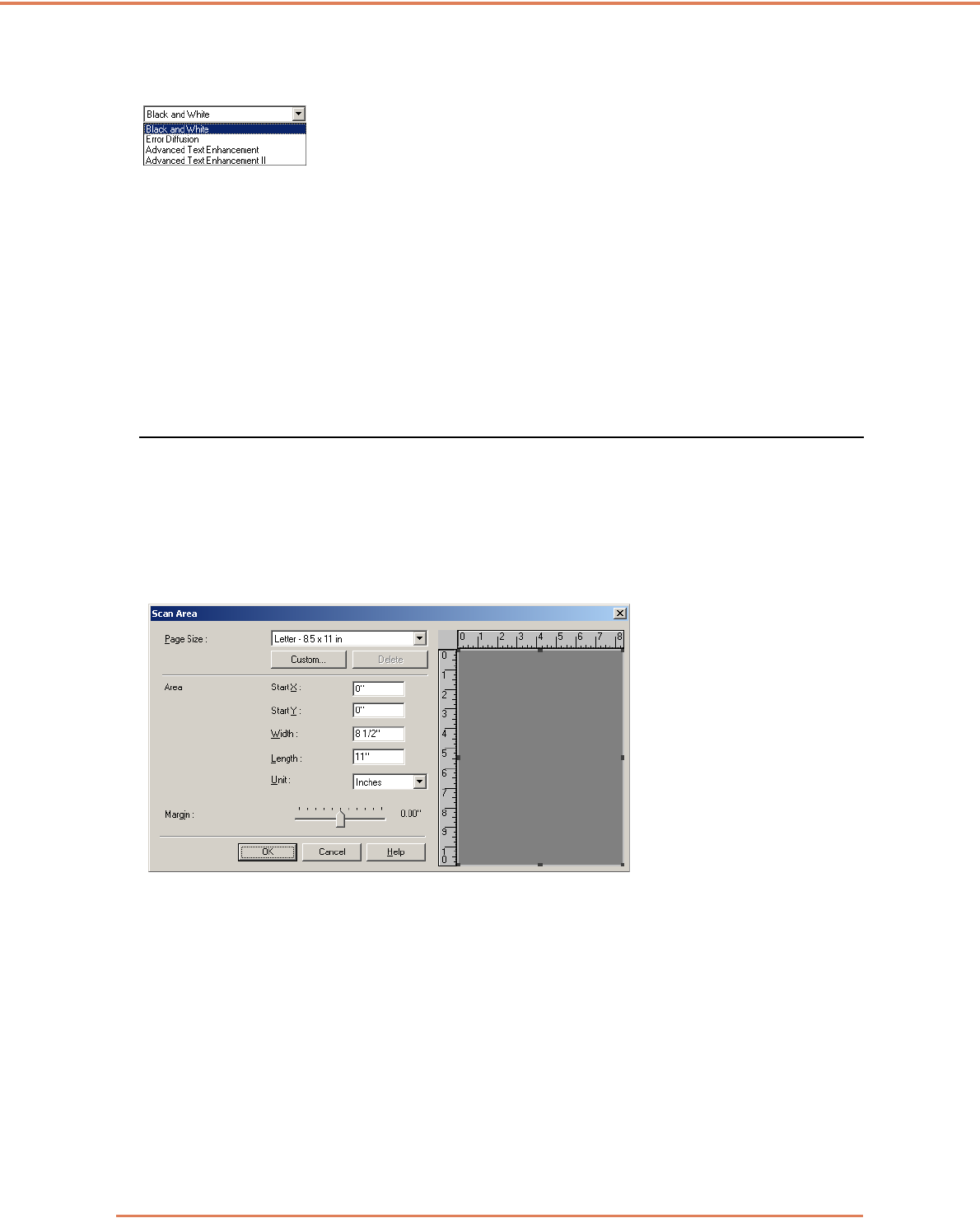
Chapter 7 ISIS/TWAIN Driver Settings
7-11
Mode in case of binary
Select the scanning mode when a page is judged to be black and white.
☞[High-Speed Text Enhancement] is disabled when [Auto Color Detection] is enabled.
Brightness
This control adjusts brightness when [Advanced Text Enhancement] or [Advanced Text
Enhancement II] is selected with Black and White mode. For other modes, brightness is set on the
[Brightness] tab sheet.
Contrast
This control adjusts contrast when [Advanced Text Enhancement II] is selected with Black and White
mode. For other modes, contrast is set on the [Brightness] tab sheet.
[Scan Area] Dialog Box
In this dialog box you can define the area of the document page to scan on a selected page size,
and register non-standard document page sizes.
The Scan Area dialog box is different for ISIS and TWAIN drivers: for the TWAIN driver, one of two
dialog box types is displayed depending on the application program used.
Scan Area Dialog Box (ISIS Driver)
Area window
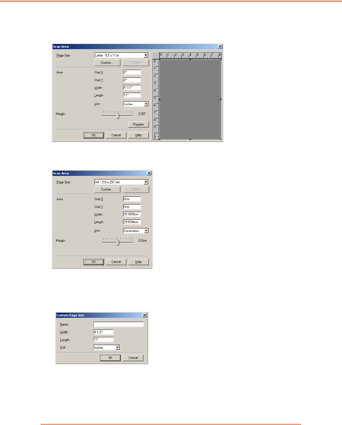
Chapter 7 ISIS/TWAIN Driver Settings
7-12
Scan Area Dialog Box (TWAIN Driver)
This dialog box appears with application programs that display the [Scan] button in the Properties
dialog box.
The Area window and [Preview] button are not displayed when using applications like the Job
Registration Tool that display the [OK] button in the Properties dialog box.
Page Size
This setting is linked to the [Page Size] setting, for selecting the size of document pages to scan.
☞Clicking the [Custom] button opens the [Custom Page Size] dialog box, where non-standard page
sizes can be registered as custom page sizes.
Area
Select the area to be scanned.
☞ Area settings here are overridden in the following cases:
• When the [Auto-detection] page size is selected
• When [Text Orientation Recognition] is enabled on the [Image processing] tab sheet
Area window
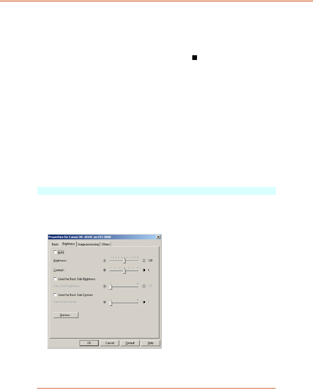
Chapter 7 ISIS/TWAIN Driver Settings
7-13
☞ When [Deskew] is enabled on the [Basic] tab sheet, the specified area may be displaced when
scanning.
Area Window
The size indicated for the Area window corresponds to the page size setting, and the area within the
panel indicates the current scanning area.
☞The scanning area can be adjusted by dragging the handles bordering the Area window with
your mouse.
☞With CapturePerfect, the last scanned image appears in the Area window.
Margin
This control adjusts the top, bottom, left and right margins around the scanning area so that you can
expand the scanning area to include the edges of a document, or reduce it to avoid black frames
around scanned images.
☞If the edges of documents are missing from scanned images, move the slider to the right to
expand the scanning area.
☞To eliminate the black frame around scanned images, reduce the scanning area by moving the
slider to the left.
☞The measurement units for margins are determined by the [Unit] setting. However, changing the
margin [Unit] setting is not possible on the extended version of the [Basic] tab sheet (P. 7 - 4 .)
Preview Button (TWAIN driver only)
Click the [Preview] button to scan one document page and display its preview image in the Area
window.
[Brightness] Tab Sheet
On the [Brightness] tab sheet, you can adjust brightness and contrast for scanning, and access
gamma settings. The availability of brightness and contrast settings depends on the mode setting on
the [Basic] tab sheet, and if [Custom] gamma setting is enabled, all settings on this tab are disabled
and cannot be changed.

Chapter 7 ISIS/TWAIN Driver Settings
7-14
The availability of brightness and contrast settings are as follows according to the mode setting on
the [Basic] tab sheet.
✓: Available for setting
— : Not available for setting, or automatically set
[Auto] Check Box
This check box is enabled when the scanning mode is [Black and White], and selecting it adjusts
brightness and contrast to match the document.
Brightness
Adjusts the brightness of images to be scanned.
☞If images are too dark or if text on the back bleeds through, you can drag the slider to the right to
increase the setting.
☞If images are too light, drag the slider to the left to decrease the setting.
☞When the [Auto] check box is selected, the slider selects a brightness level to be used for
automatic adjustment.
Contrast
Adjusts the contrast of images to be scanned.
[Use Back Side Brightness] Check Box
If the brightness of the front and back of the document pages is different, select this to adjust only
the brightness of the back side.
[Use Back Side Contrast] Check Box
If the contrast of the front and back of the document pages is different, select this to adjust only the
contrast of the back side.
[Gamma] Button
This button opens the [Gamma Settings] dialog box, where you can adjust the gamma curve.
Scanning mode Auto Brightness Contrast Back Side
Brightness
Back Side
Contrast
Black and White ✓✓ ✓ ✓ ✓
Error Diffusion — ✓✓✓ ✓
Advanced Text Enhancement — ✓—— —
Advanced Text Enhancement II — ✓✓——
High-Speed Text Enhancement — ✓✓——
256-level Gray — ✓✓✓ ✓
24-bit Color — ✓✓✓ ✓
Auto Color Detection — ✓✓✓ ✓
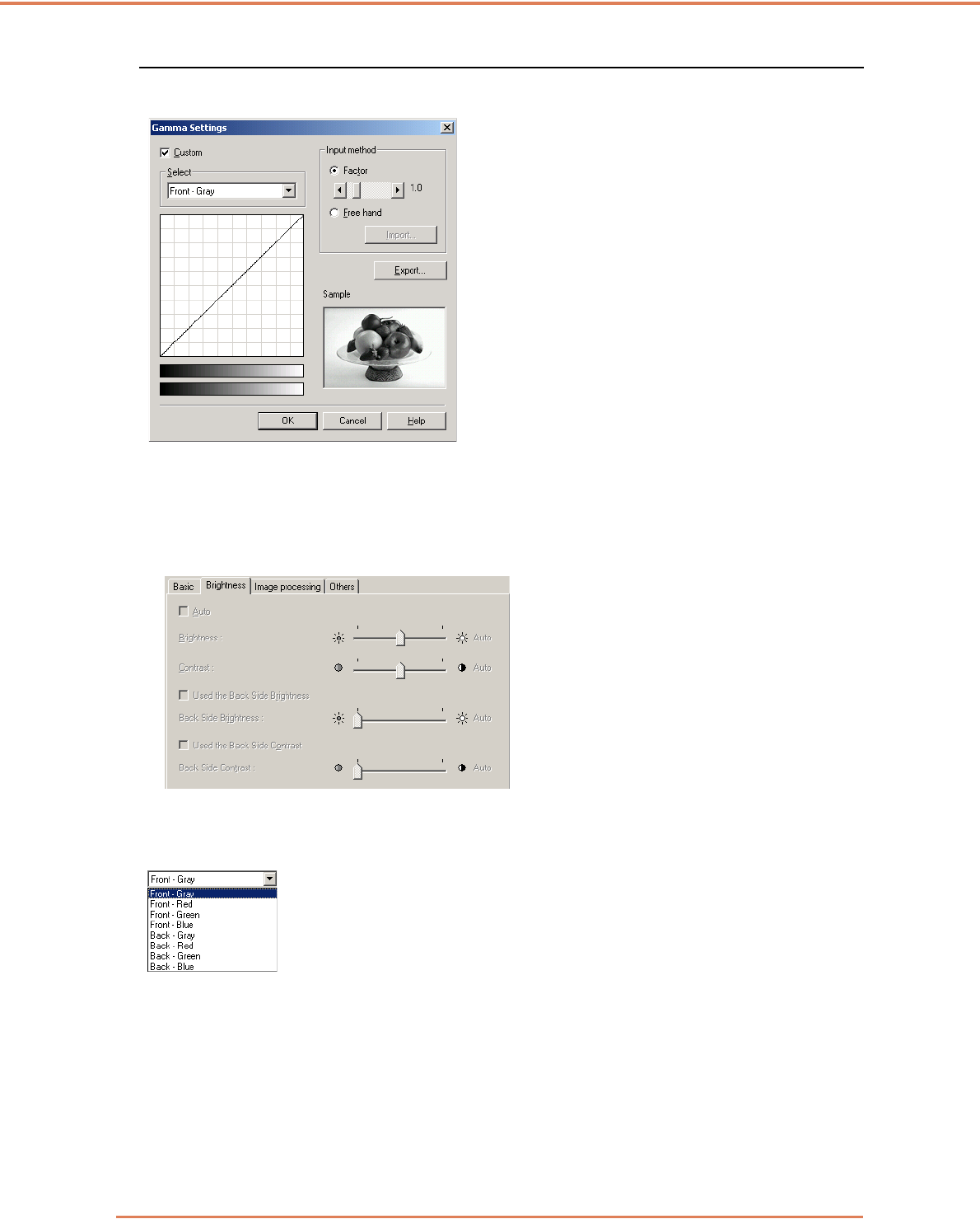
Chapter 7 ISIS/TWAIN Driver Settings
7-15
[Gamma Settings] Dialog Box
Use the [Gamma Settings] dialog box to adjust the gamma correction value.
[Custom] Check Box
Select this check box to set custom gamma correction.
☞When [Custom] gamma setting is selected, all settings on the [Brightness] tab sheet are made
automatically.
Select
Select the side and color for custom setting.
☞The color bar and color of the sample image are changed to show the specified color.
Input method
Select the setting method for gamma correction.
[Factor]
Move the slider left or right to adjust gamma correction factor between 0.2 and 5.0.
☞The gamma correction value, Gamma Curve Graph and sample image color are interlinked.
☞Clicking at a point in the Gamma Curve Graph with your mouse changes the gamma curve and
color of the sample image to match that point.
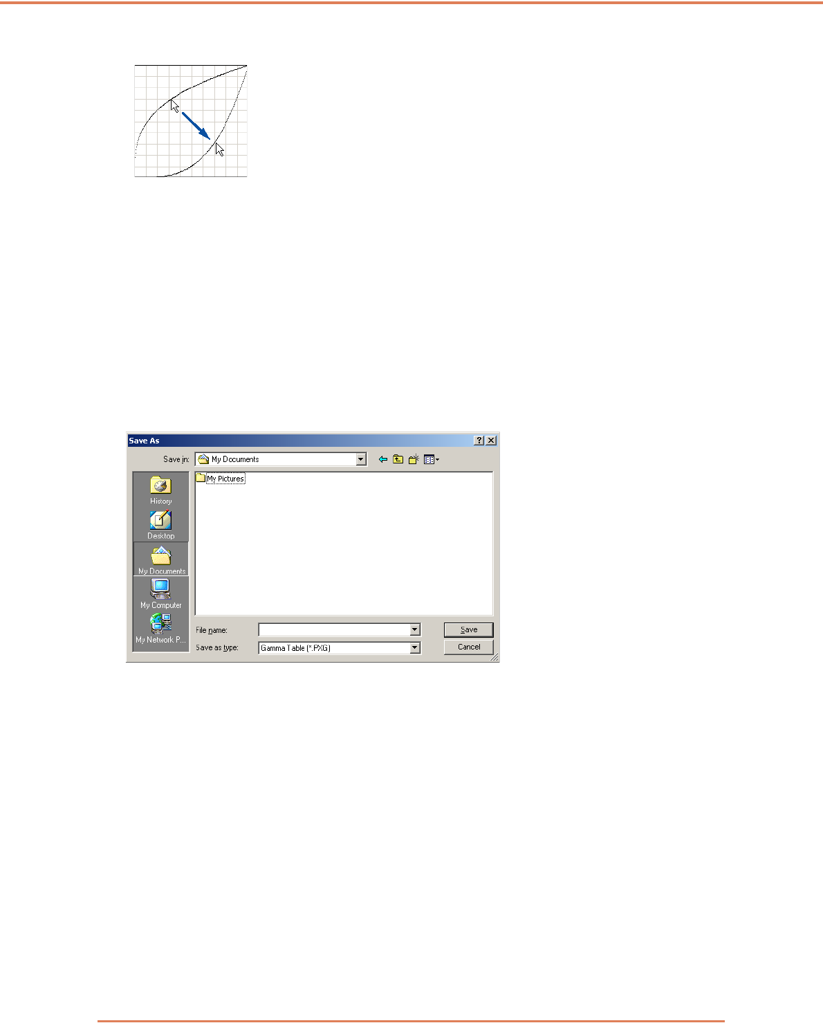
Chapter 7 ISIS/TWAIN Driver Settings
7-16
☞You can also move the gamma curve by dragging it with the mouse.
[Freehand]
The output value for a particular input value in the gamma table can be specified with the mouse.
☞Click any point in the Gamma Curve Graph to set that point as an output value.
☞Drag the mouse on the Gamma Curve Graph to set the output value according to the mouse
movement.
[Import] Button
Clicking this button loads gamma table data (*.png file) that was previously stored with the [Export]
button.
☞Imported gamma data is reflected in the Gamma Curve Graph.
[Export] Button
Clicking this button exports the custom gamma curve settings as a gamma table file (*.pxg.)
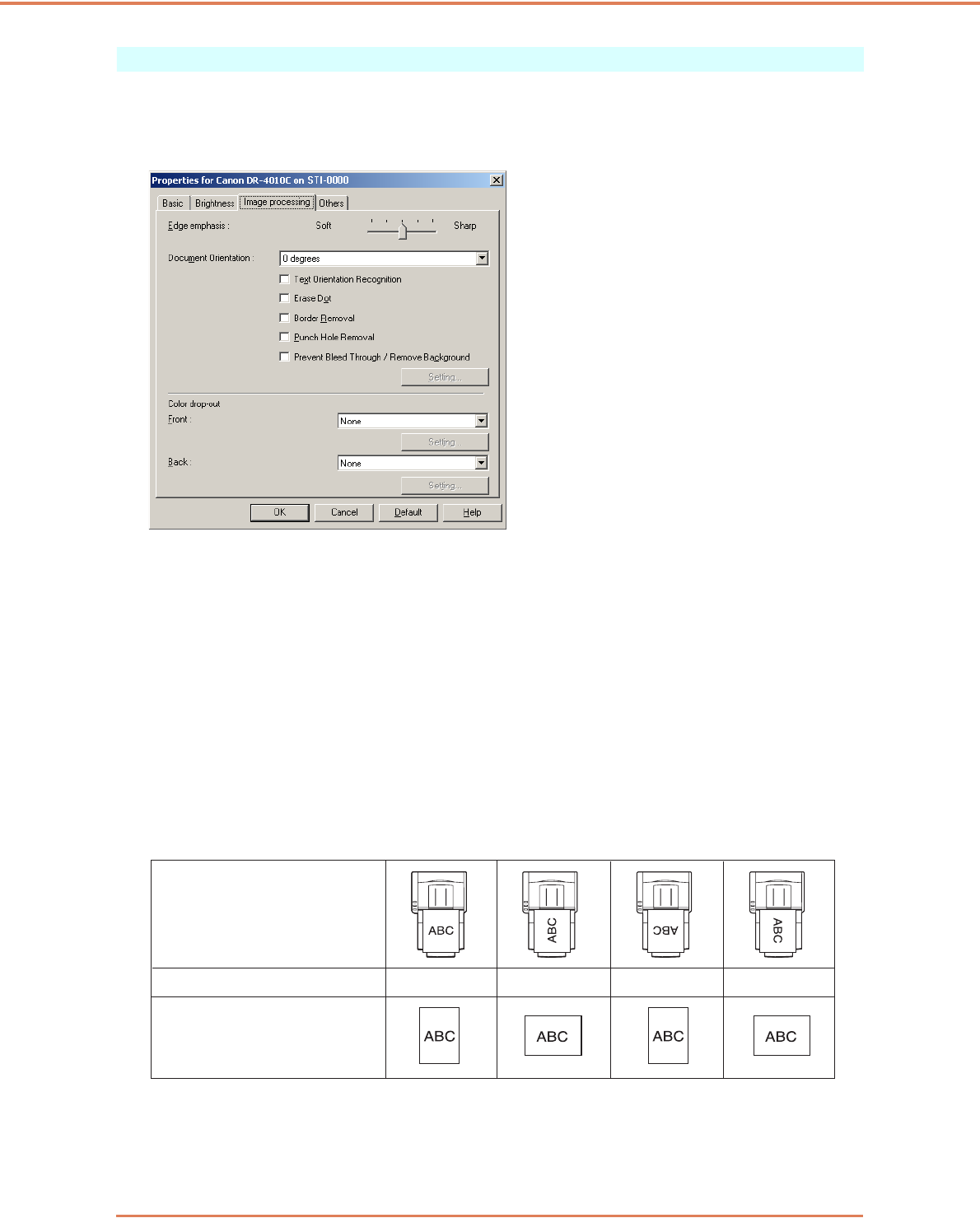
Chapter 7 ISIS/TWAIN Driver Settings
7-17
[Image processing] Tab Sheet
The [Image processing] tab sheet provides settings affecting processing of scanned images. Some
settings may be disabled depending on the mode settings on the [Basic] tab sheet. Refer to “Mode-
Dependent Function Limitations,” on p. 7-7 for details.
[Reverse Image] Check Box (TWAIN driver only)
The document is scanned with black and white reversed when scanning in black and white (binary)
mode.
[Edge Emphasis]
Adjusts image contours. Move the slider toward Soft to soften image contours, or toward Sharp to
sharpen image contours.
[Document Orientation]
This setting selects an angle (0, 90, 180 or 270 degrees) to rotate scanned images for orientation
normalization.
☞Scanned images are rotated as follows according to the orientation of loaded documents and the
selected rotation angle.
Feeder documents:
face up
Flatbed documents:
face down
Image rotation (clockwise) 0° 90° 180° 270°
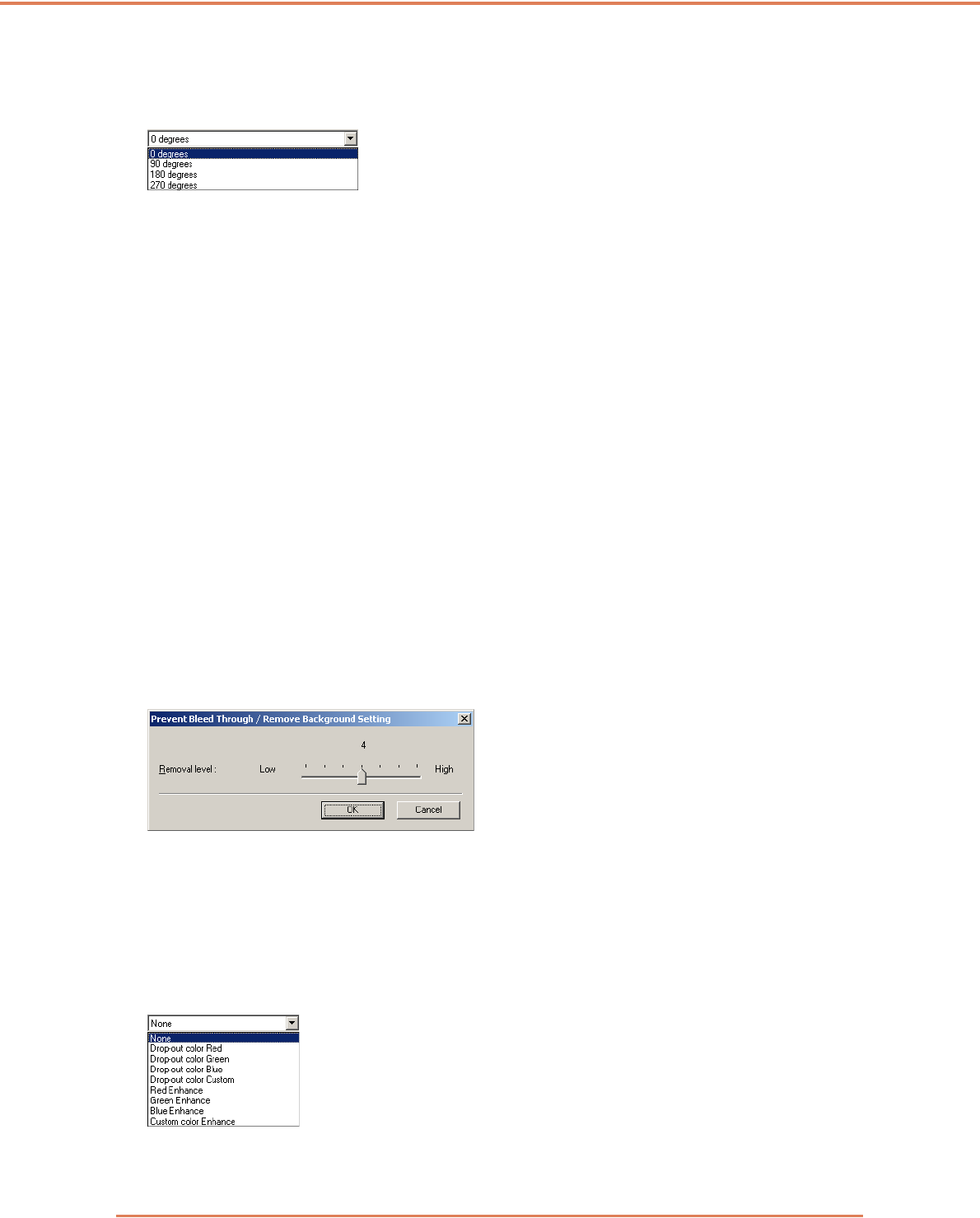
Chapter 7 ISIS/TWAIN Driver Settings
7-18
[Text Orientation Recognition] Check Box
Select this check box to detect text orientation in scanned images, and rotate images in 90º
increments as needed to normalize orientation.
☞When [Text Orientation Recognition] is selected, [Image Rotation] and area settings in the Scan
Area dialog box are disabled.
☞Some application programs do not support [Text Orientation Recognition]. Please disable [Text
Orientation Recognition] if your application program behaves abnormally when it is enabled.
[Erase Dot] Check Box
Select this to remove isolated black pixels (3×3 dots or smaller) from a white background, or isolated
white pixels from a black background.
[Border Removal] Check Box
Select this to remove black borders surrounding scanned images.
[Punch Hole Removal] Check Box
Select this to remove the black spots from scanned images when scanning documents with punch
holes.
☞If punch holes are located within text or graphics in the document, they may be misidentified as
graphics, and may not be removed.
[Prevent Bleed Through / Remove Background] Check Box
Select this to Prevent Bleed Through when scanning thin document pages and those with dark
content on the back side, or to remove the background from document images.
When this check box is selected, the [Setting] button is enabled to allow adjustment of the removal
level in the [Prevent Bleed Through / Remove Background Setting] dialog box.
[Reverse Image] Check Box (TWAIN driver only)
Select this check box to reverse (swap) black and white when scanning documents as black and
white (binary) images.
Color Drop-Out
These selections are enabled for scanning modes other than 24-bit Color, so that you can select a
primary color (red, green, blue) or gray to be ignored (dropped out) or enhanced.
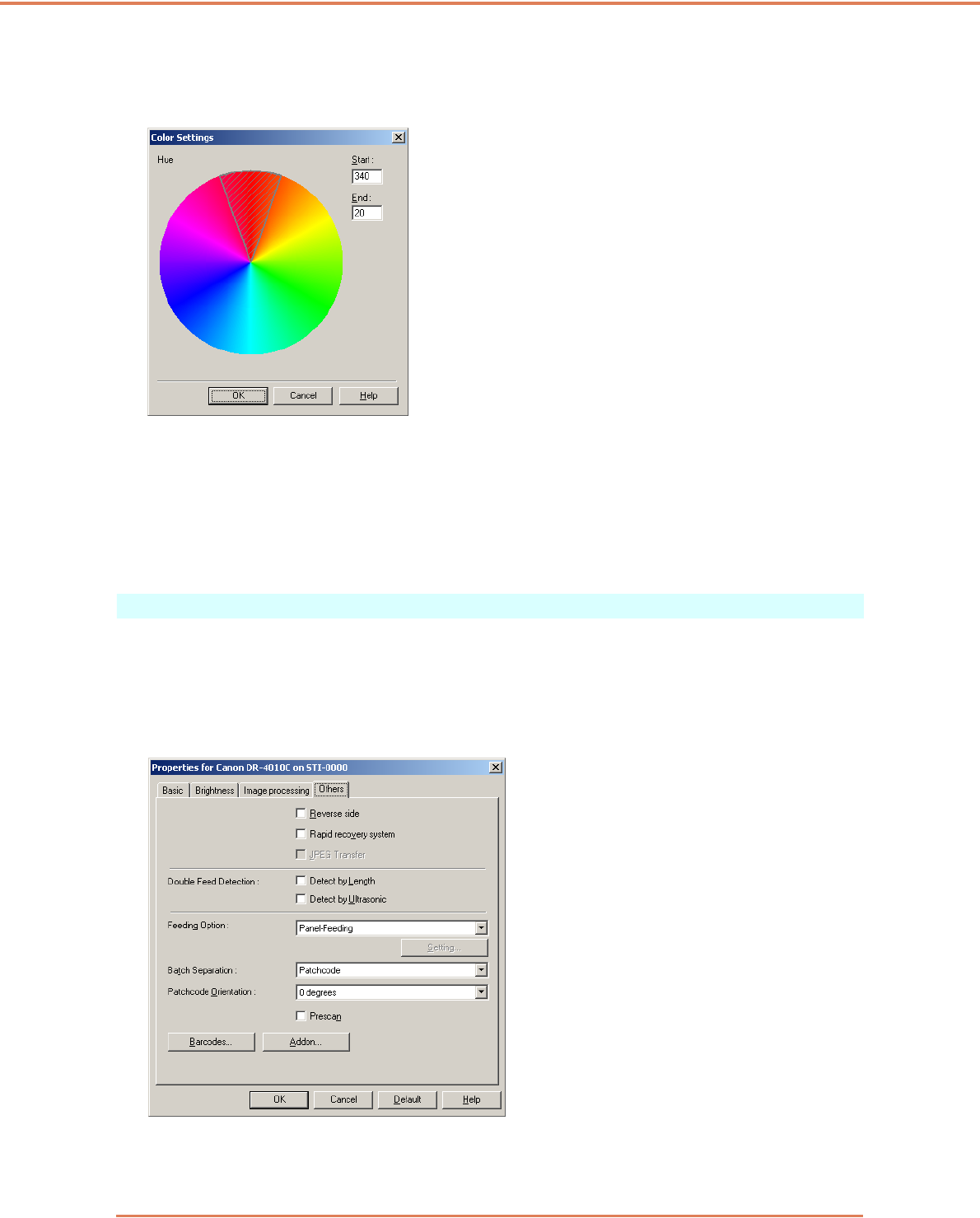
Chapter 7 ISIS/TWAIN Driver Settings
7-19
The [Setting] buttons are enabled when [Drop-out color Custom] or [Custom Color Enhance] is
selected, so that you can specify a color range in the [Color Settings] dialog box for drop-out or
enhancement.
☞The color range within the shaded (cross-hatched) area is dropped out or enhanced.
☞You can move the shaded area by dragging with the mouse.
☞You can change the specified color range by dragging the edges of the shaded area.
☞Because your operating environment affects the colors you specify on screen, they may not
match those actually dropped out or enhanced: that is, the colors you specify may not match
those processed.
[Others] Tab Sheet
The settings on the [Others] tab sheet are different for the ISIS and TWAIN drivers. Also, some
settings may be disabled depending on the mode settings on the [Basic] tab sheet. Refer to “Mode-
Dependent Function Limitations,” on p. 7-7 for details.
[Others] Tab Sheet (ISIS driver)
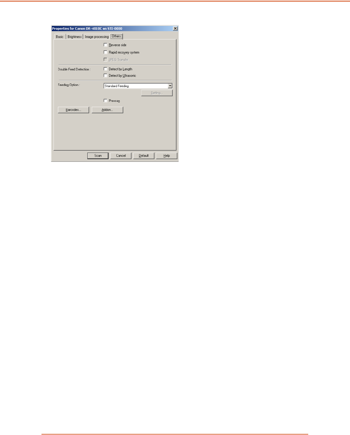
Chapter 7 ISIS/TWAIN Driver Settings
7-20
[Others] Tab Sheet (TWAIN driver)
[Reverse side]
Scanning occurs as follows depending on the scanning side settings.
☞When this check box is selected and the scanning side is set to [Simplex], only the back of each
page is scanned.
☞When this check box is selected and the scanning side is set to [Duplex] or [Skip Blank Page], the
back of each page is scanned first, followed by the front.
[Rapid Recovery System] Check Box
If a paper jam causes paper transport to stop while scanning, scanning stops without sending an
error notification to the application program. After fixing the cause of the stoppage, you can continue
scanning with the standard operations.
[JPEG Transfer] Check Box
When this check box is selected, scanned image data is always compressed to JPEG format within
the scanner for output to the computer.
Scanned image data is output from the scanner as an uncompressed or JPEG transfer, depending
on instructions from the ISIS/TWAIN driver or application program.
☞Uncompressed transfers output raw scanned image data, so when the image data is large,
significant time may be required for transfer from the scanner to the computer.
☞JPEG transfer is good for color and grayscale images, as scanned image data is JPEG-
compressed within the scanner before output.
This reduces the size of the image data for output, so transfer time from the scanner to the
computer is shortened.
When JPEG Transfer is selected, image data from the scanner is always output as JPEG-
compressed data.
☞When the uncompressed saving format is selected in the application program, JPEG-compressed
image data is reconverted to uncompressed data before transfer to the application. Image quality
is degraded slightly as a result.
☞This check box setting is ignored if the application program requests a JPEG transfer.
☞Of course application program requests depend on the specifications of the particular program.
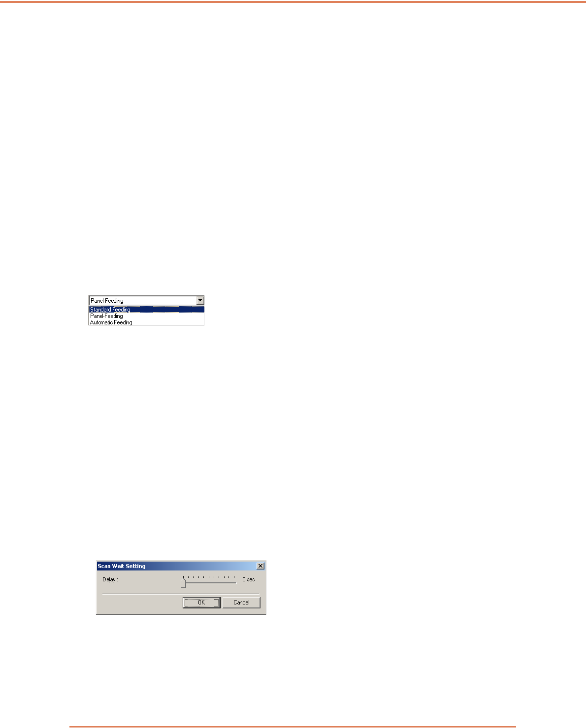
Chapter 7 ISIS/TWAIN Driver Settings
7-21
Double Feed Detection
This function stops document transport when double feeding of document pages is detected, and
provides selection of the detection method to suit the documents to be scanned.
[Detect by Length]
This method of double feed detection is good for batch scanning of same-size documents: the length
of the first document page fed is taken as a standard, and when a subsequent document is detected
to be 50 mm longer (or shorter) than the standard, a double feed is judged to have occurred, and
document transport is stopped.
[Detect by Ultrasonic]
This method of double feed detection is good for batch scanning of different-size documents: the
overlapping of documents transported in a batch is detected ultrasonically, and if the detected
overlap is 50 mm or more, a double feed is judged to have occurred and document transport is
stopped.
☞Both detection methods can be used at the same time.
☞If the documents overlap by less than 50 mm, or if the documents cling (such as from static
electricity,) ultrasonic detection of double feeds may be unreliable.
Feeding Option
Here you can select the feeding method for document scanning.
[Standard Feeding]
This feeding method is good for scanning small batches of documents that are loaded one batch at
a time: scanning stops when the loaded documents have been scanned.
[Panel Feeding]
This feeding method is good for scanning batches of documents of different sizes: after loading the
documents, press the Job button (assigned as a Start button on the scanner) to start scanning, and
press the assigned Stop button to stop scanning.
☞When scanning documents with different-size pages, after loading the documents, you can adjust
the document guide position.
[Automatic Feeding]
This feeding method is good for scanning batches of same-size documents: scanning starts when
the scanner detects loaded documents, and stops when you press the Stop button.
☞When [Automatic Feeding] is selected, the [Setting] button is enabled to allow setting the delay
time from when a loaded document is detected until scanning starts. (See “Scanning Multiple
Documents,” on p. 9-3.)
Batch Separation (ISIS driver only)
Items available for selection depend on the Feeding Option setting: select batch separation timing
(for when to start scanning) according to the batch separation capabilities provided by the
application program.
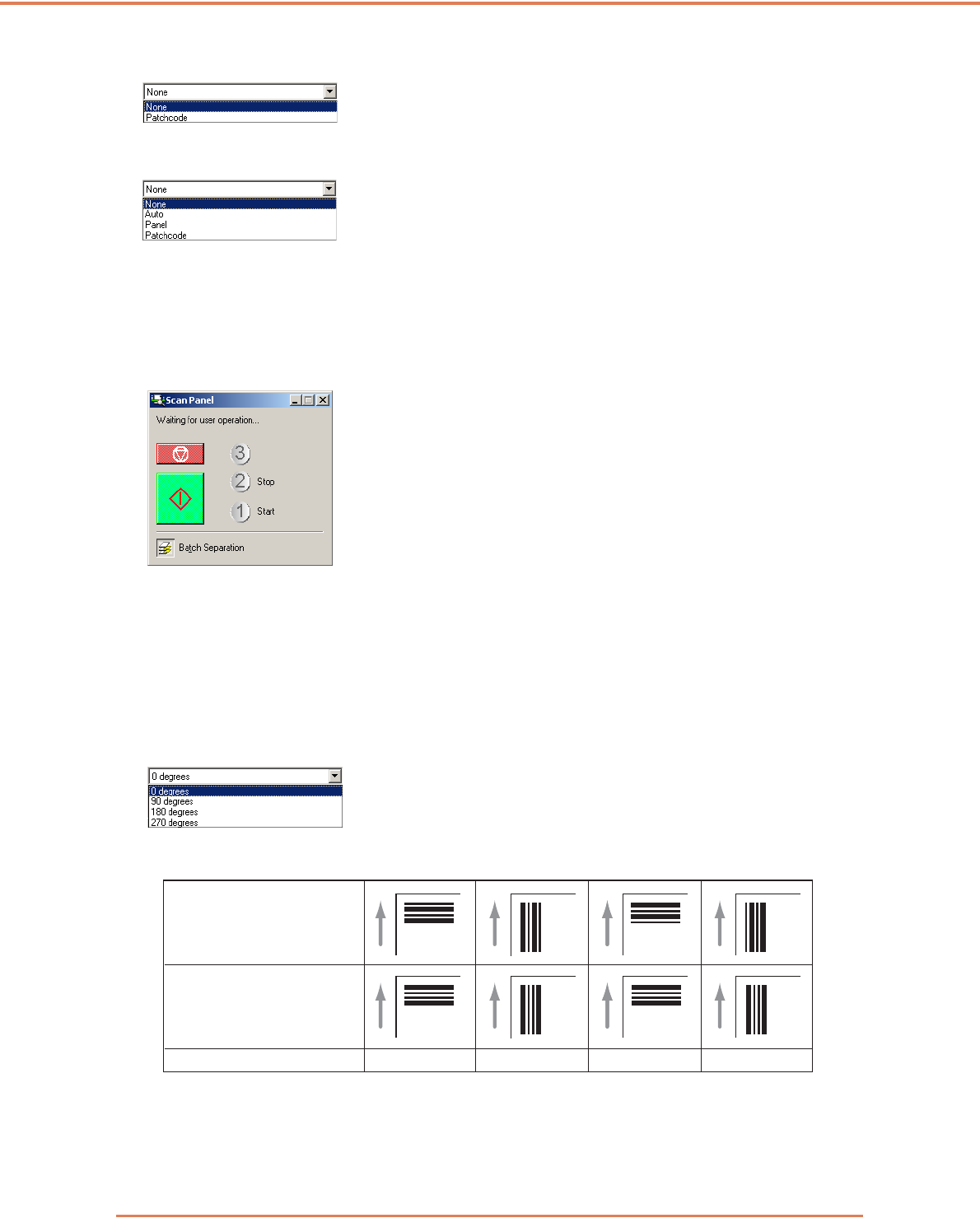
Chapter 7 ISIS/TWAIN Driver Settings
7-22
With the [Standard Feeding] Feeding Option
With the [Automatic Feeding] or [Panel Feeding] Feeding Option
[Auto]
Each batch of documents is saved with different file names.
[Panel]
Document batches are separated when the [Batch Separation] button on the Scan Panel is pressed.
(See “Scan Panel,” on p. 3-21.)
[Patchcode]
Batches are separated whenever a patchcode sheet is detected between documents. (See “3-6
Using Patchcode Sheets,” on p. 3-23.)
☞When [Patchcode] is selected, the [Folio] Scanning Side setting on the [Basic] tab sheet is not
available.
Patchcode Orientation (ISIS driver only)
When [Patchcode] batch separation is enabled, you can select patchcode orientation here.
☞Settings for various patchcode types and orientations on document pages are as follows.
[Prescan] Check Box
When this check box is selected, the first document page is prescanned and displayed in the
Prescan panel when scanning is first started. Continue scanning after you confirm or adjust
brightness and contrast of the scanned image in the Prescan window. (See “Prescan,” on p. 9-7.)
Patchcode orientation 0° 90° 180° 270°
Patch T
FILE A
Patch II
FILE B
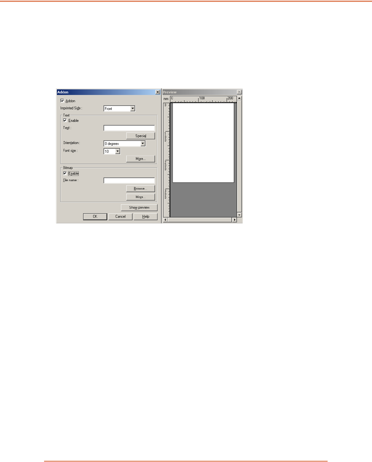
Chapter 7 ISIS/TWAIN Driver Settings
7-23
[Barcodes] Button
This is enabled when the optional barcode module is installed: click it to open the Barcode dialog
box and make settings affecting barcode detection in documents. For details, see the ISIS/TWAIN
driver Help, or contact your supplier.
[Addon] Button
This button opens the [Addon] dialog box, where you can make setting for adding text or bitmap
images to scanned document images. (See “Addon Dialog Box,” on p. 7-24.)
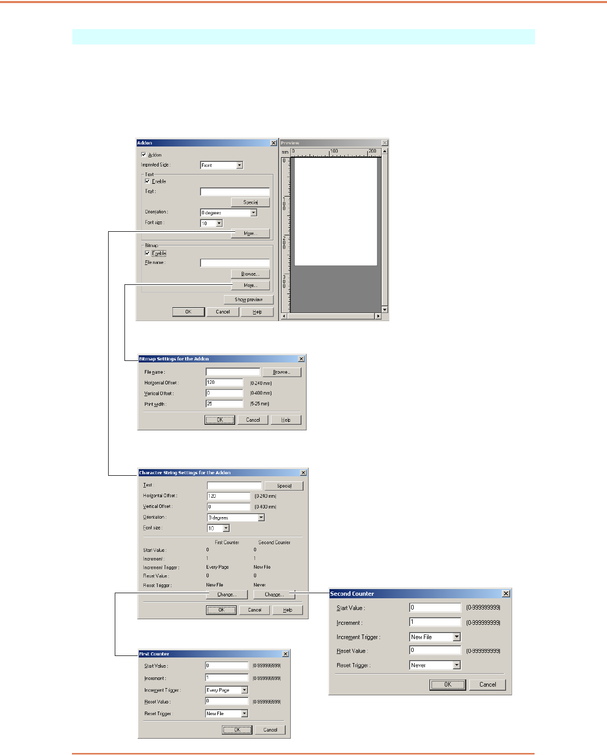
Chapter 7 ISIS/TWAIN Driver Settings
7-24
Addon Dialog Box
The [Addon] dialog box provides access to the following dialog boxes, where you can make setting
for adding text or bitmap images to scanned document images.
The [Addon] dialog box enables you to make setting for adding text or bitmap images to scanned
document images.
Addon Dialog Box
Bitmap Settings for the Addon Dialog Box (See p. 7-27.)
Character String Settings for the Addon
Dialog Box (See p. 7-27.)
Second Counter Settings Dialog Box
First Counter Settings Dialog Box
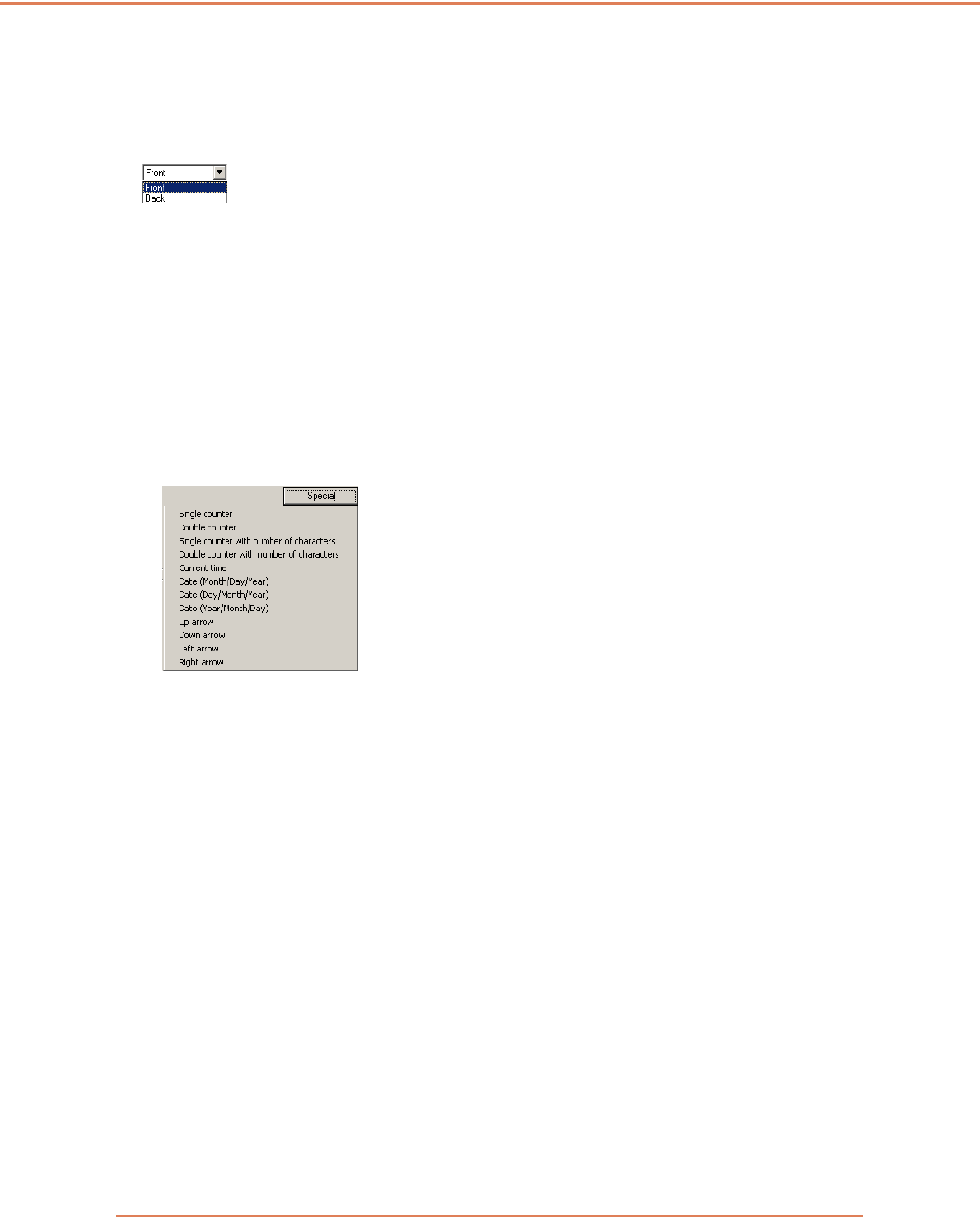
Chapter 7 ISIS/TWAIN Driver Settings
7-25
[Addon] Check Box
Select this check box to apply text or bitmap images to scanned document images.
Imprinter Side
Select the side on which to apply your text or images.
[Enable] Check Box
Select this check box to enable the application of add-on text.
Text
Enter the text string to be applied.
☞The following characters can be entered.
• Numerals 0 to 9
• Alphabetic characters A to Z and a to z
• Punctuation and symbols: !" '# $ % &'( ) * + - . , / : ; < > =?@[ ] { } ~ ` \
☞Enter special text such as counters, dates and arrows from the list that appears by clicking the
[Special] button. The selected abbreviation is inserted into the text string.
[Single counter] abbreviation: <C>
Inserts one 9-digit counter.
[Double counter] abbreviation: <CC>
Inserts two 9-digit counters.
[Single counter with number of characters] abbreviation: <Cx>
A dialog box appears in which to specify the number of characters of the single counter. The
specified number of characters of the single counter will be inserted into scanned images.
[Double counter with number of characters] abbreviation: <CxCx>
A dialog box appears in which to specify the number of characters of the double counter. The
specified number of characters of the double counter will be inserted into scanned images.
[Current time] abbreviation: <TIME>
Inserts the time of scanning using 8 digits in 24-hour format.
[Date (Month/Day/Year)] abbreviation: <MDY>
Inserts the date of scanning using 10 characters in Month/Day/Year format.
[Date (Day/Month/Year)] abbreviation: <DMY>
Inserts the date of scanning using 10 characters in Day/Month/Year format.
[Date (Year/Month/Day)] abbreviation: <YMD>
Inserts the date of scanning using 10 characters in Year/Month/Day format.
[Up arrow] abbreviation: <U>
Inserts an up arrow () symbol.
[Down arrow] abbreviation: <D>
Inserts a down arrow () symbol.
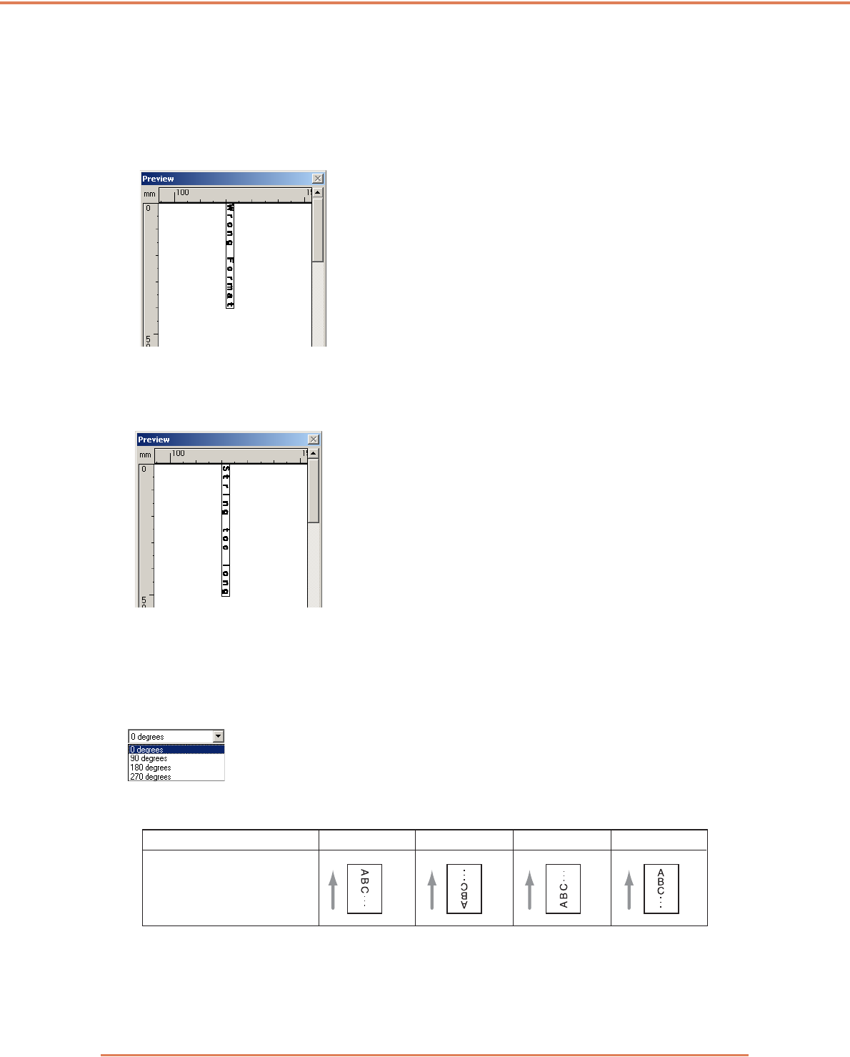
Chapter 7 ISIS/TWAIN Driver Settings
7-26
[Left arrow] abbreviation: <L>
Inserts a left arrow () symbol.
[Right arrow] abbreviation: <R>
Inserts a right arrow () symbol.
☞Special text can only be entered for one type of counter. If entered for two counter types, the
Preview panel displays an error message.
☞Add-on text may consist of up to 96 characters. However, the actual number of characters may be
limited by font size. If the number of characters to apply exceeds the maximum allowed, the
Preview panel displays an error.
☞When inserting special text, the actual number of characters to apply can become quite large,
even though little text is actually entered.
[Orientation]
Specify the orientation for the text to be applied.
☞Text orientation relative to the feeding direction is as follows.
[Font size]
Select the font size of the text to be applied.
Font size (points):3, 4, 6, 8, 9, 10, 12, 16, 18 , 20, 24, 28, 30 or 38
Orientation 0° 90° 180° 270°
Addon
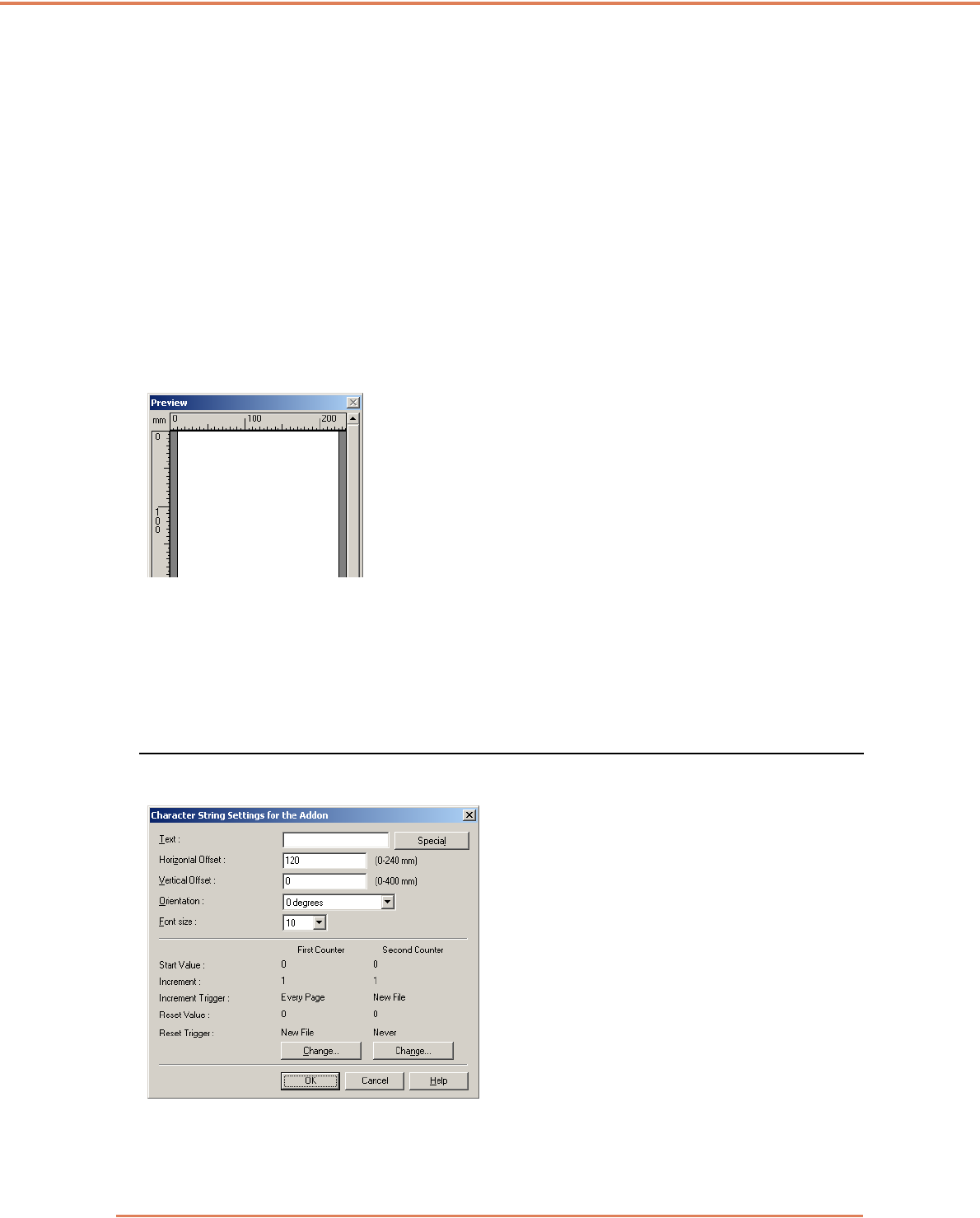
Chapter 7 ISIS/TWAIN Driver Settings
7-27
☞When add-on text is applied to an image, the size of the characters depends on the scan
resolution.
[Enable] Check Box
Select this check box to enable application of bitmap images to scanned images.
☞When adding a bitmap image, it is processed when scanning is started. This can cause some
delay before scanning actually begins, depending on the size and settings of the bitmap image.
☞When adding a bitmap image, a message is displayed until scanning begins.
[File name]
Specify the file name of the image to be applied.
☞The bitmap image with the specified file name is rotated 90 degrees when applied.
☞Only bitmap images (*.bmp files) can be applied.
Preview Panel
The specified content to be applied is displayed in the Preview panel.
☞You can magnify the Preview display in four steps with the left mouse button, and reduce it with
the right mouse button.
[Show preview] button
Click this button to activate the Preview panel.
Text/Bitmap Settings Dialog Box
Here you can make settings for text or bitmaps to be applied to scanned images.
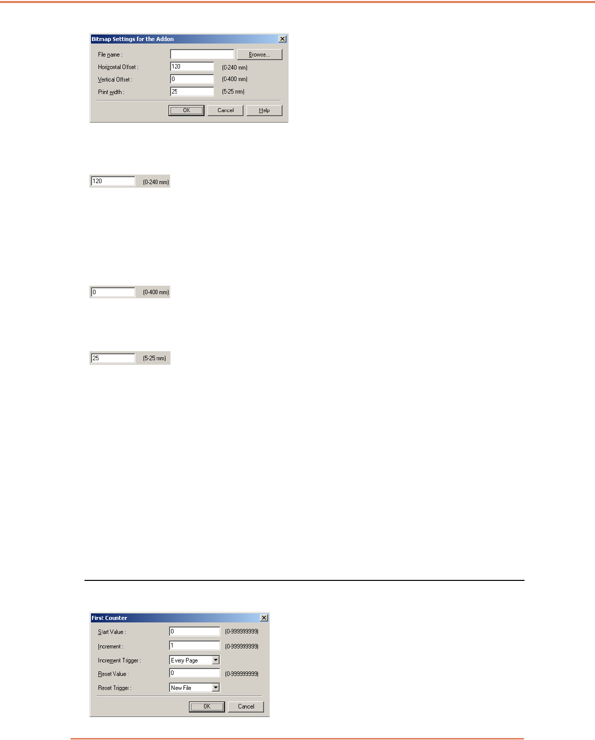
Chapter 7 ISIS/TWAIN Driver Settings
7-28
[Horizontal Offset]
Enter the desired offset from the edge of the document feeder inlet.
☞When applying an add-on to the front side, enter the offset from the left side of the feeder inlet.
☞When applying an add-on to the back side, enter the offset from the right side of the feeder inlet.
☞The entered offset is the distance to the left end of the applied text (or bitmap image.)
[Vertical Offset]
Enter the distance from the top edge of the page.
Print width
Enter the width of the bitmap image to be applied.
☞The bitmap image will be rotated 90º clockwise and compressed to the specified width before it is
applied.
☞An error message may appear depending on the size of the image file. If this happens, reduce the
Print width.
First Counter
This is the current setting for the single counter, or for the first counter if double counters are
selected.
☞Settings can be changed in the First Counter settings dialog box.
Second Counter
This is the current setting for the second counter if double counters are selected.
☞Settings can be changed in the Second Counter settings dialog box.
First and Second Counter Settings Dialog Boxes
Make settings for add-on counters.

Chapter 7 ISIS/TWAIN Driver Settings
7-29
Start Value
Enter the start value for the counter.
Increment
This is the counter increment value. The counter increments by the value entered here.
Increment Trigger
Specifies the type of event that triggers a counter increment.
[New File] (ISIS driver only)
The counter increments when a batch separation occurs according to the Batch Separation settings
on the [Others] tab sheet. (See “Batch Separation (ISIS driver only),” on p. 7-21.)
[Every Page]
Increments once per page.
[None]
No counter increment occurs.
Reset Value
Select the initial value when the counter is reset.
Reset Trigger
Specifies the type of event that resets the counter.
[New File] (ISIS driver only)
The counter is reset when a batch separation occurs according to the Batch Separation settings on
the [Others] tab sheet. (See “Batch Separation (ISIS driver only),” on p. 7-21.)
[Every Page]
Resets the counter once per page.
[None]
No counter reset occurs.
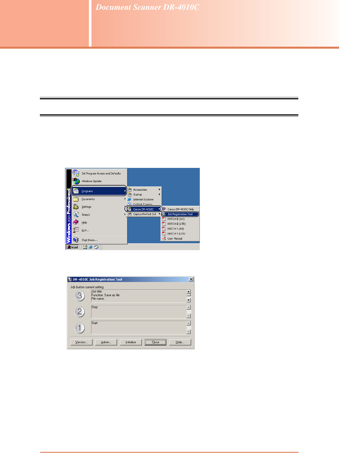
8-1
Chapter 8
Job Registration Tool Settings
This chapter describes Job Registration Tool settings for job functions. Refer to Section “3-4 Job
Function,” on p. 3-9 for details.
8-1 Starting the Job Registration Tool
The Job Registration Tool is a TWAIN-compliant application program that installs with the ISIS/
TWAIN driver, and is started by the following procedure.
1Click the Windows [Start] button, and click then [Programs] ([All Programs] for Windows XP)
Æ [DR-4010C] Æ [Job Registration Tool].
The Job Registration Tool starts. (See “8-2 Job Registration Tool Settings Dialog Box,” on p. 8-
2.)
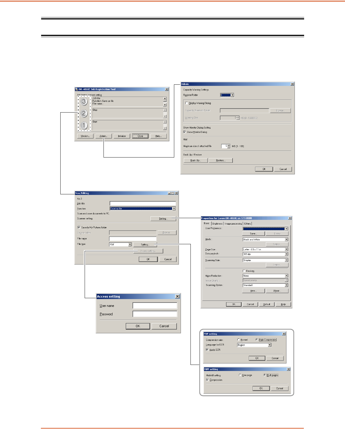
Chapter 8 Job Registration Tool Settings
8-2
8-2 Job Registration Tool Settings Dialog Box
The Job Registration Tool Settings dialog box provides access to the [New/Editing ] dialog box and
the [Admin] dialog box, and the New/Edit dialog box provides access to function setting dialog
boxes. (See “[New/Editing] Dialog Box,” on p. 8-4.)
Job Registration Tool Dialog Box
(p. 8-3)
[New/Editing] Dialog Box (p. 8-4)
Access Setting
Scanner Settings Dialog Box
PDF/TIFF Settings
[Admin] Dialog Box (p. 8-8)
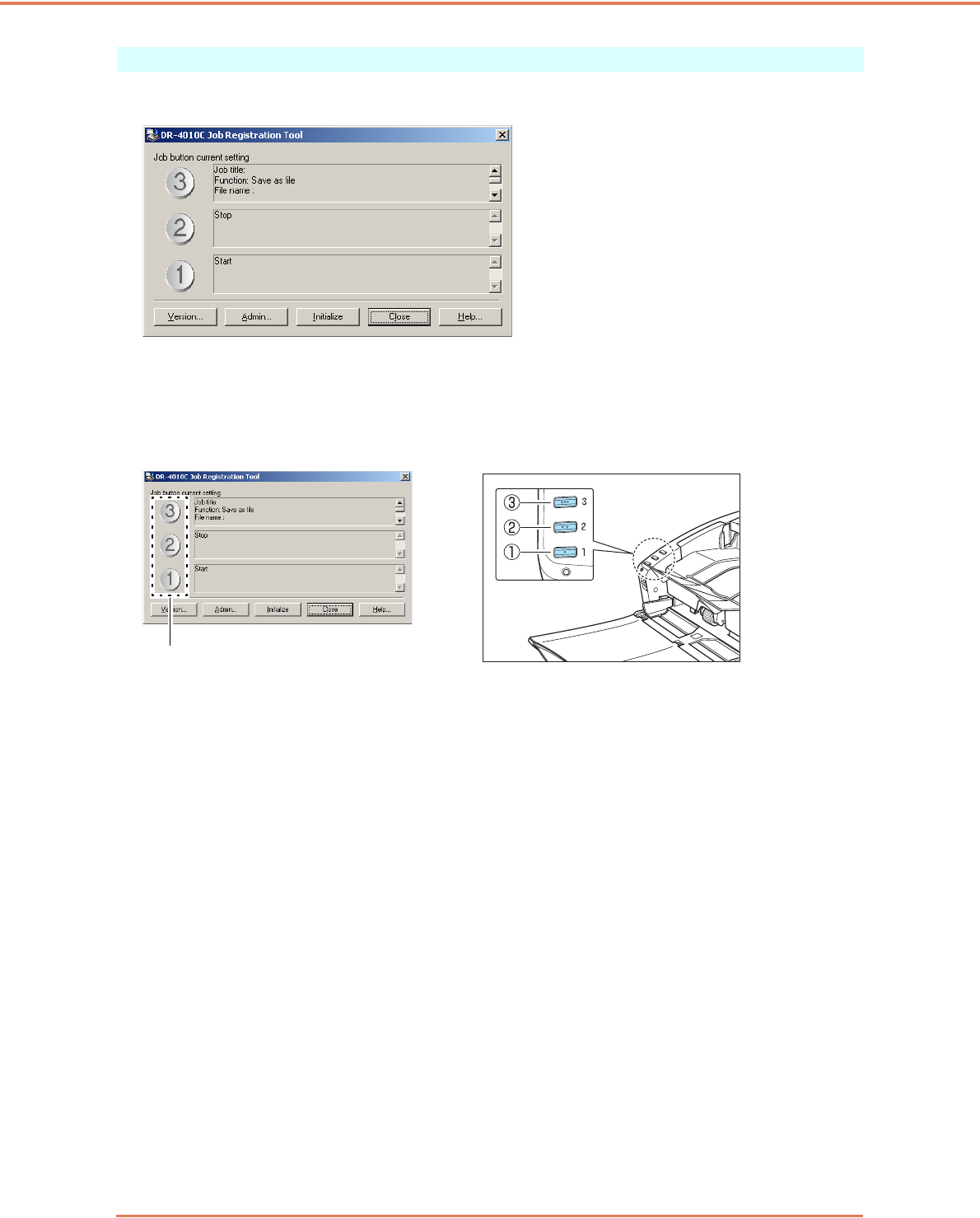
Chapter 8 Job Registration Tool Settings
8-3
Job Registration Tool Dialog Box
This dialog box appears when the Job Registration Tool is started from the Programs menu.
Job Button Settings List
The displayed job buttons correspond to those on the scanner, showing their currently assigned
settings. Clicking on the job buttons (a, b and c) opens the New/Editing dialog box. (See “[New/
Editing] Dialog Box,” on p. 8-4.)
[Version] Button
Displays the version of the Job Registration Tool.
[Admin] Button
Opens the Admin dialog box. (See “Administration Dialog Box,” on p. 8-8.)
[Initialize] Button
Returns the settings to their default state.
[Close] Button
Closes the Job Registration Tool Settings dialog box.
[Help] Button
Displays the Help for the Job Registration Tool.
Job Button Settings
Job Buttons
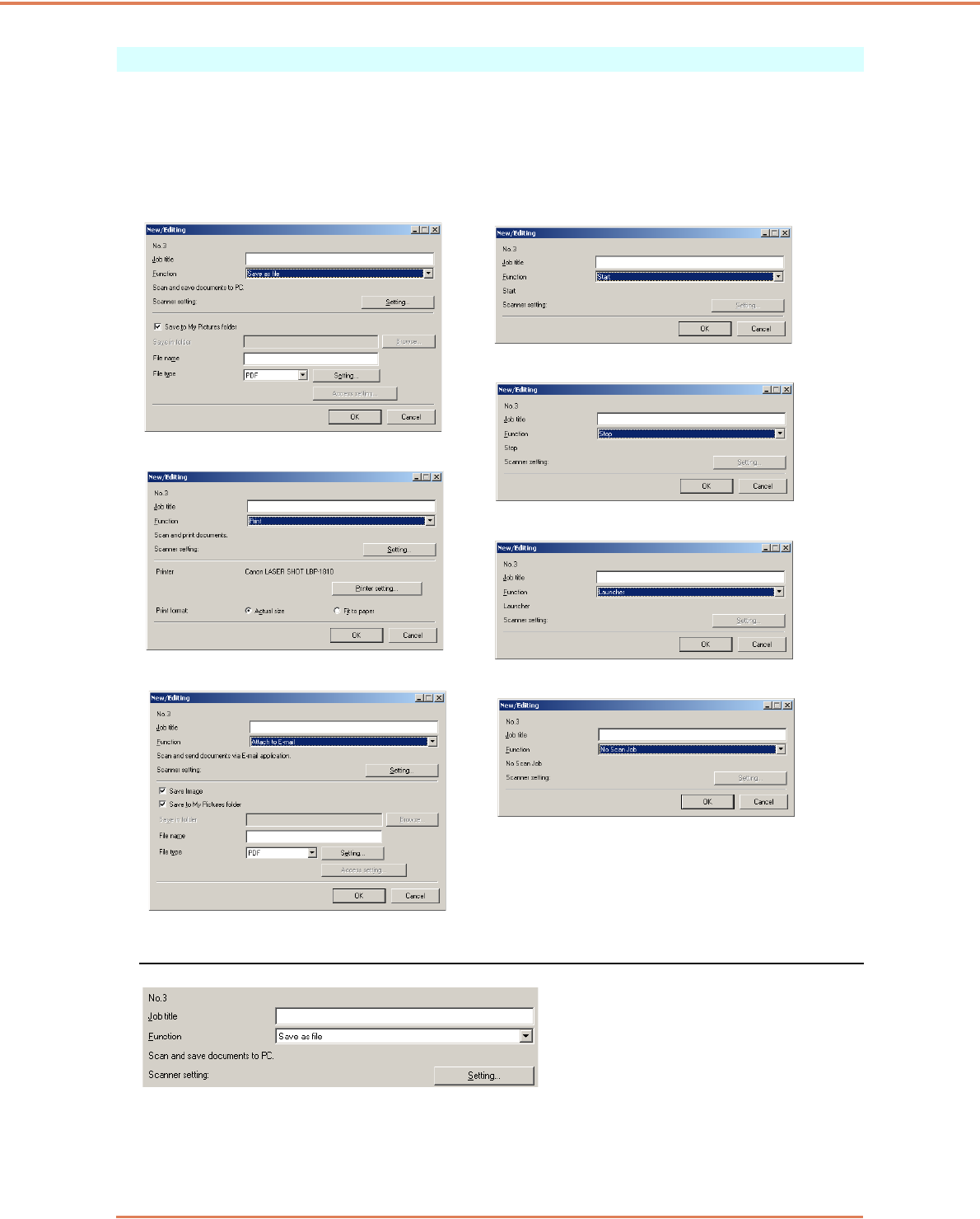
Chapter 8 Job Registration Tool Settings
8-4
[New/Editing] Dialog Box
The [New/Editing] dialog box appears when you click a Job button in the Job Registration Tool dialog
box.
The [New/Editing] dialog box appears as follows depending on the function settings registered to the
Job buttons.
Settings Common to Each Function
Job Number [No. 1 to No. 3]
Shows the selected job button number. Settings are registered to the job button with the displayed
number.
Save as file Start
Print
Stop
Launcher
Attach to E-mail No scan job
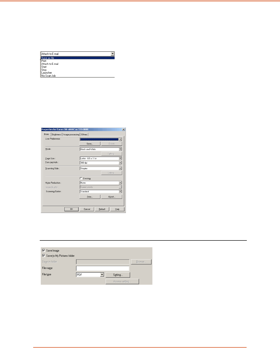
Chapter 8 Job Registration Tool Settings
8-5
Job title
Enter the job title to be displayed in the Job Button Settings list.
☞Job titles may consist of up to 29 alphanumeric characters.
Function
Select the function to register to this job.
☞When changing functions, the [New/Editing] dialog box is changed. (P.8-4)
☞Applications programs started by the [Launcher] function use Windows "Event" function settings.
(See “About Launcher,” on p. 3-11.)
Scanner setting
When the “Save as file,” “Print” or “Attach to E-mail” function is selected, Scanner settings are
enabled, and you can press the [Setting] button to make scanner settings.
☞Refer to Chapter 7, “ISIS/TWAIN Driver Settings” for scanner setting procedures.
Settings to Save Image Files (Functions: Save as file and Attach to E-mail)
[Save Image] Check Box
This check box appears when [Attach to E-mail] is selected as the [Function]. Select this box to save
scanned images.
[Save to My Pictures folder] Check Box
Saves image files to My Pictures in the My Documents folder.
☞When this check box is not selected, the [Save in folder] and [Access setting] buttons are enabled.
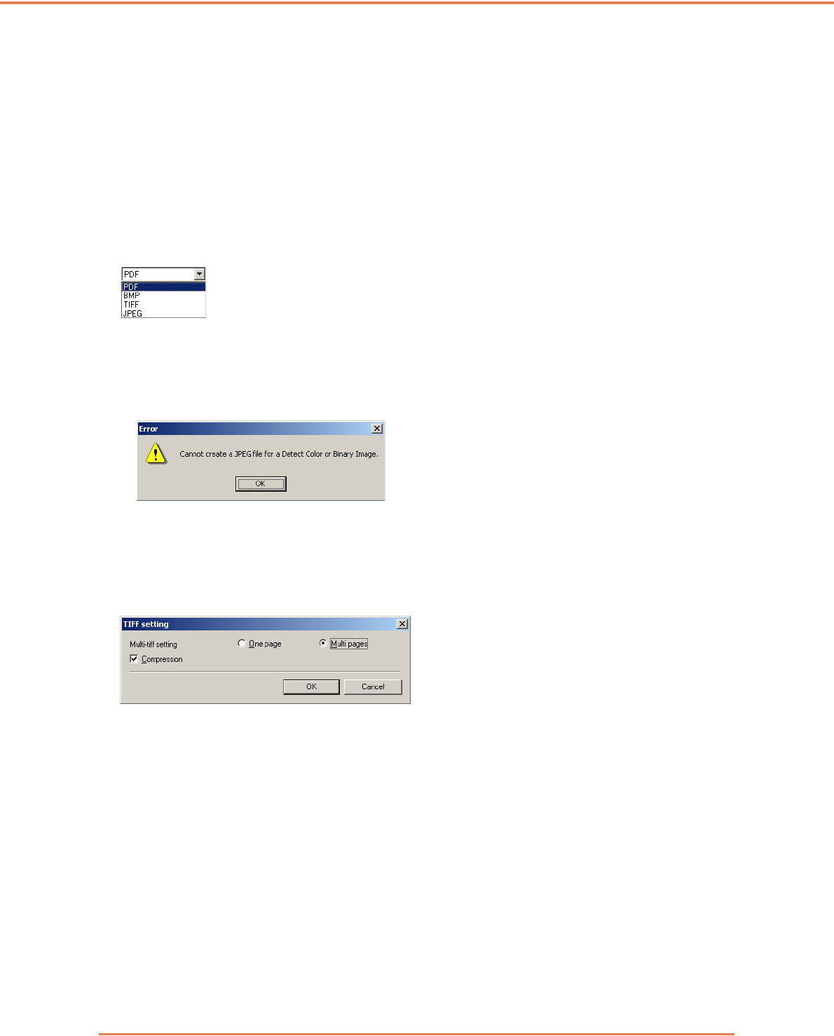
Chapter 8 Job Registration Tool Settings
8-6
Save in folder
When the [Save to My Pictures folder] check box is not selected, this is enabled for you to enter a
folder name in which to save scanned images. You can also select a folder by clicking the [Browse]
button.
File name
Enter a name for the files to save.
☞File names may consist of up to 32 alphanumeric characters.
☞A time stamp is appended to the file name indicating the time of scanning.
File type
Enter the file format for saved files.
☞Selecting [TIFF] or [PDF] enables the [Setting] button.
☞When the [Auto Color Detection] scanner setting is selected, an error is displayed if [JPEG] is
selected when you click the [OK] button. If this error appears, select another file format or change
the scanner setting.
[Setting] Button
This button is enabled to display the corresponding setting dialog box when the [TIFF] or [PDF] file
format is selected.
TIFF Settings Dialog Box
[Multi-tiff setting]
Select the method for saving image files when scanning multi-page documents.
• Select [One page] to save each page in its own image file.
• Select [Multi pages] to save all pages in one image file.
[Compression] Check Box
Select this check box to compress images saved to files. Black and white (binary) images are
compressed in CCITT Group 4 format, and grayscale and color images in JPEG format. When this
check box is not selected, the saved files are much larger.
☞CCITT Group 4: This compression format was designed for data communications (such as with
fax devices) of black and white (binary) images.
☞JPEG: This compression format is for saving grayscale and color images. When the
[Compression] check box is selected, a standard level of JPEG compression is applied.
☞If your application program does not support the above compression formats, you may be unable
to open scanned image files. In this case disable [Compression] when scanning.
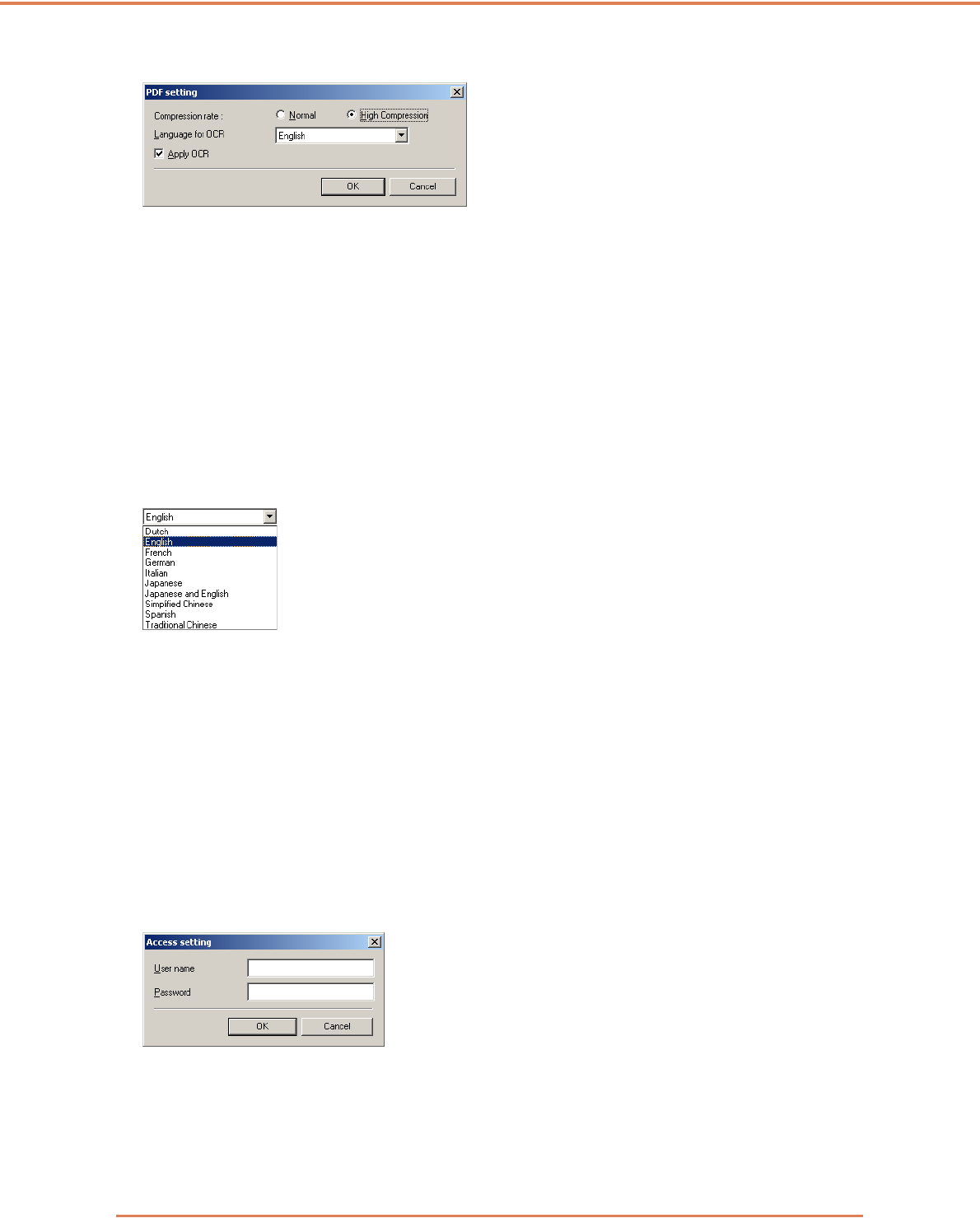
Chapter 8 Job Registration Tool Settings
8-7
PDF Settings Dialog Box
Compression rate
Select the compression rate for PDF files.
• Select [Normal] to save with standard compression.
• Select [High Compression] to save files with high compression. Although file size is reduced,
image quality may be slightly degraded.
☞The Compression rate setting is enabled when the scanner is set to [256-level Gray] or [24-bit
Color] mode. When [Black and White] or [Error Diffusion] binary image scanning mode is
selected, file size depends on the content of the scanned document.
Language for OCR
When the [Apply OCR] check box is selected, the target language for OCR can be selected in the list
box.
☞Chinese OCR with the [Simplified Chinese] or [Traditional Chinese] settings requires a Chinese
language environment to display properly.
[Apply OCR] Check Box
Select this check box to enable recognition of the text within images and to save the recognized text
data with the image.
☞Characters within document images are recognized as text and saved as appended text data in
PDF (*pdf) files.
[Access setting] Button
This button is enabled when the [Save to My Pictures folder] check box is not selected, allowing
entry of the user name and password required to access the shared network folder specified for
[Save in folder].
☞Access to shared network folders may be restricted to users with certain access permission. In
this case, users cannot access the shared folder without entering the correct user name and
password.
Confirm the access rights for the shared network folder with the network administrator, then enter
the user name and password.
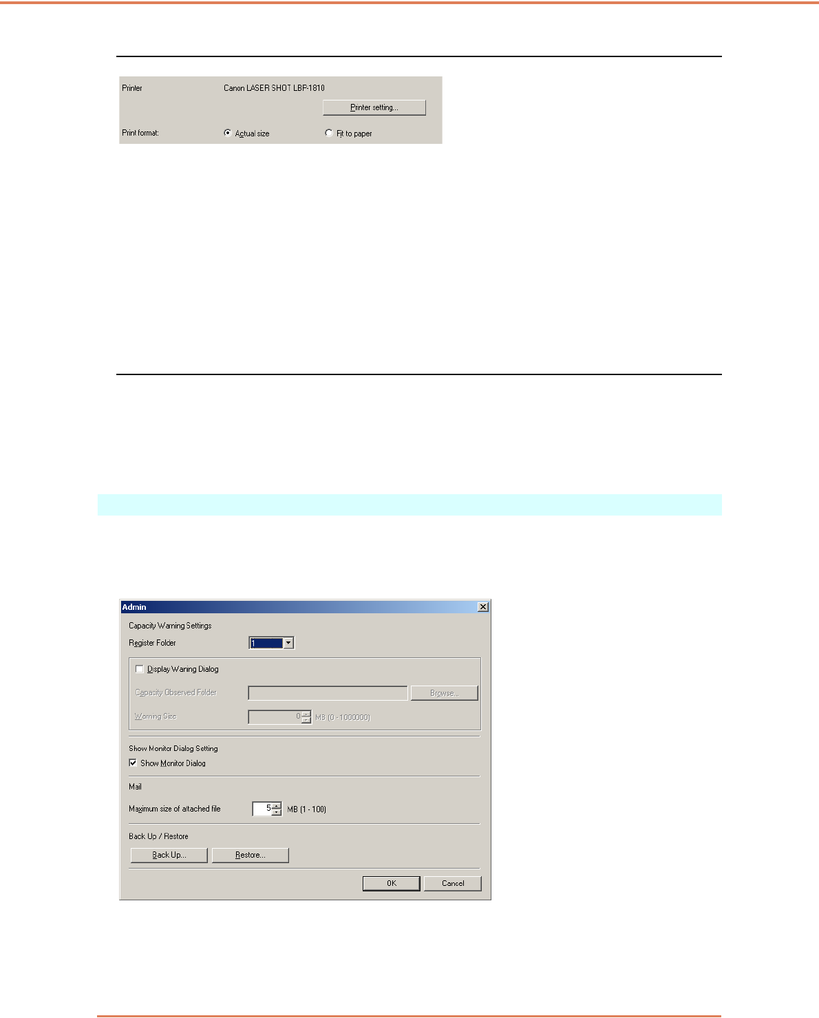
Chapter 8 Job Registration Tool Settings
8-8
Setting to Print Scanned Images (Function: Print)
[Printer]
Shows the printer to use for printing images. Click the [Printer setting] button to change printer
settings.
[Print format]
Select whether to resize images for printing.
• Select [Actual size] to print images the same size as their original documents.
• Select [Fit to paper] if the scanned documents were larger than the printer paper, to resize the
images to the printer paper size.
Buttons
[OK] button
Click this button to accept changes and return to the Job Registration Tool dialog box.
[Cancel] button
Click this button to reject changes and return to the Job Registration Tool dialog box.
Administration Dialog Box
This dialog box appears when you click the [Admin] button in the Job Registration Tool dialog box.
Here you can set [Capacity Warning Settings], [Show Monitor Dialog Setting], [Maximum size of
attached file] and job data [Back Up/Restore].
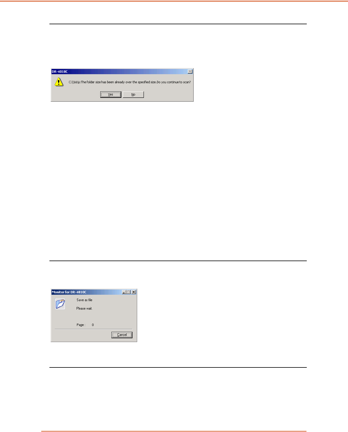
Chapter 8 Job Registration Tool Settings
8-9
Settings for Monitoring the Folder for Saved Images
[Capacity Warning Settings]
The Capacity Warning Settings allow you to specify in advance the folder for saving image files, and
the space to be available for saving files. If the space required to save a file would exceed the
specified Warning Size when starting to scan or while scanning, a warning message appears.
☞A warning size (capacity) can be specified for up to five folders, with the number (1 to 5) of the
folder to be selected registered by [Register Folder].
[Display Warning Dialog] Check Box
Select this check box when you want to limit space available in a destination folder, by registering
the folder number and specifying a warning size.
[Capacity Observed Folder]
Specify a folder to monitor for available space
[Warning Size]
Enter the maximum total size for all files saved to the specified folder.
☞When saving to removable storage media such as CD-R, specify the maximum capacity of the
media.
☞When folder monitoring ([Display Warning Dialog]) is enabled, a warning message appears when
starting to scan if the total size of the files in the specified folder exceeds the specified limit.
☞If a warning message appears, follow the instructions in the message to either continue scanning
or change the save destination first.
Monitor Job Dialog Settings
[Show Monitor Dialog] Check Box
Select this check box to display the Monitor dialog to display job progress while scanning.
Setting the Maximum Size of E-Mail Attachments
[Maximum size of attached file]
Specify the maximum image file size that can be attached when [Attach to E-mail] is selected. When
the scanned image size reaches the specified maximum, a message appears and scanning stops.
☞The maximum size of attached files must not exceed the limit determined by the mail server. Ask
your e-mail system administrator for the attachment size limit of the mail server.
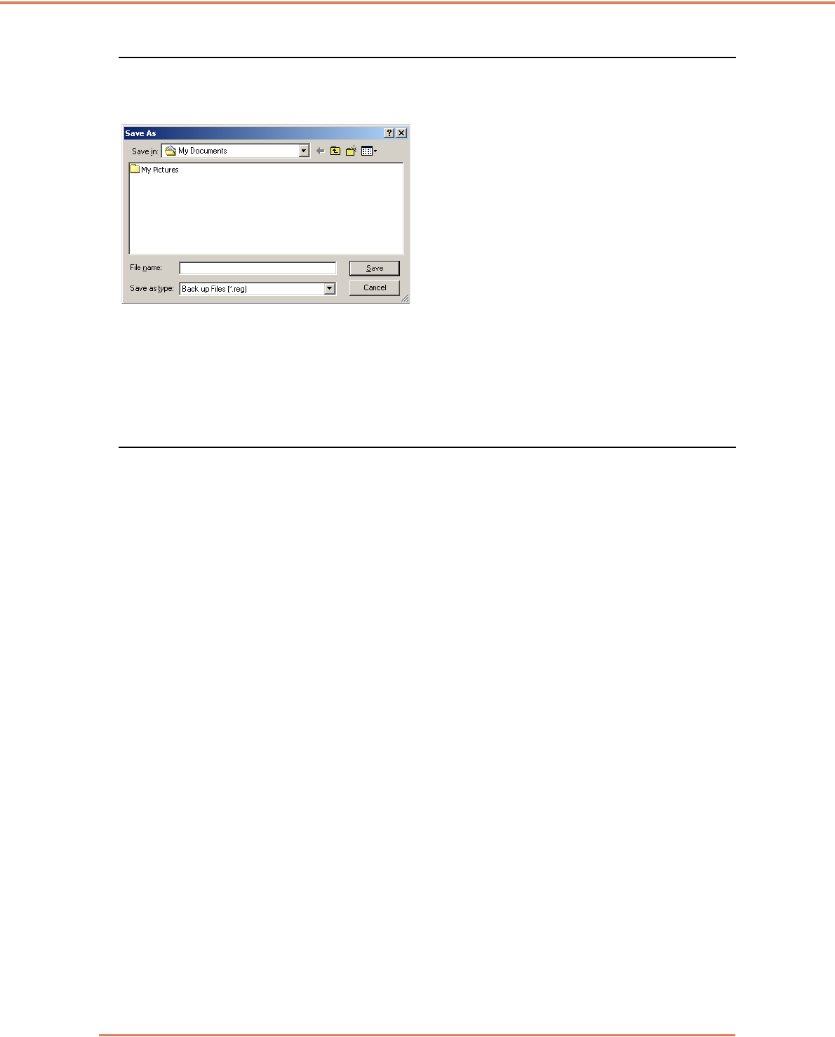
Chapter 8 Job Registration Tool Settings
8-10
[Back Up / Restore] Settings
[Back Up] Button
Writes a backup file (*.reg) of registered job data to the specified folder.
[Restore] Button
Restores the job data from a stored backup file (*.reg.)
☞If the currently registered job number is the same as that of an existing backup file, the existing
backup file is overwritten by the registered job.
Buttons
[OK] button
Click this button to accept changes and return to the Job Registration Tool dialog box.
[Cancel] button
Click this button to reject changes and return to the Job Registration Tool dialog box.
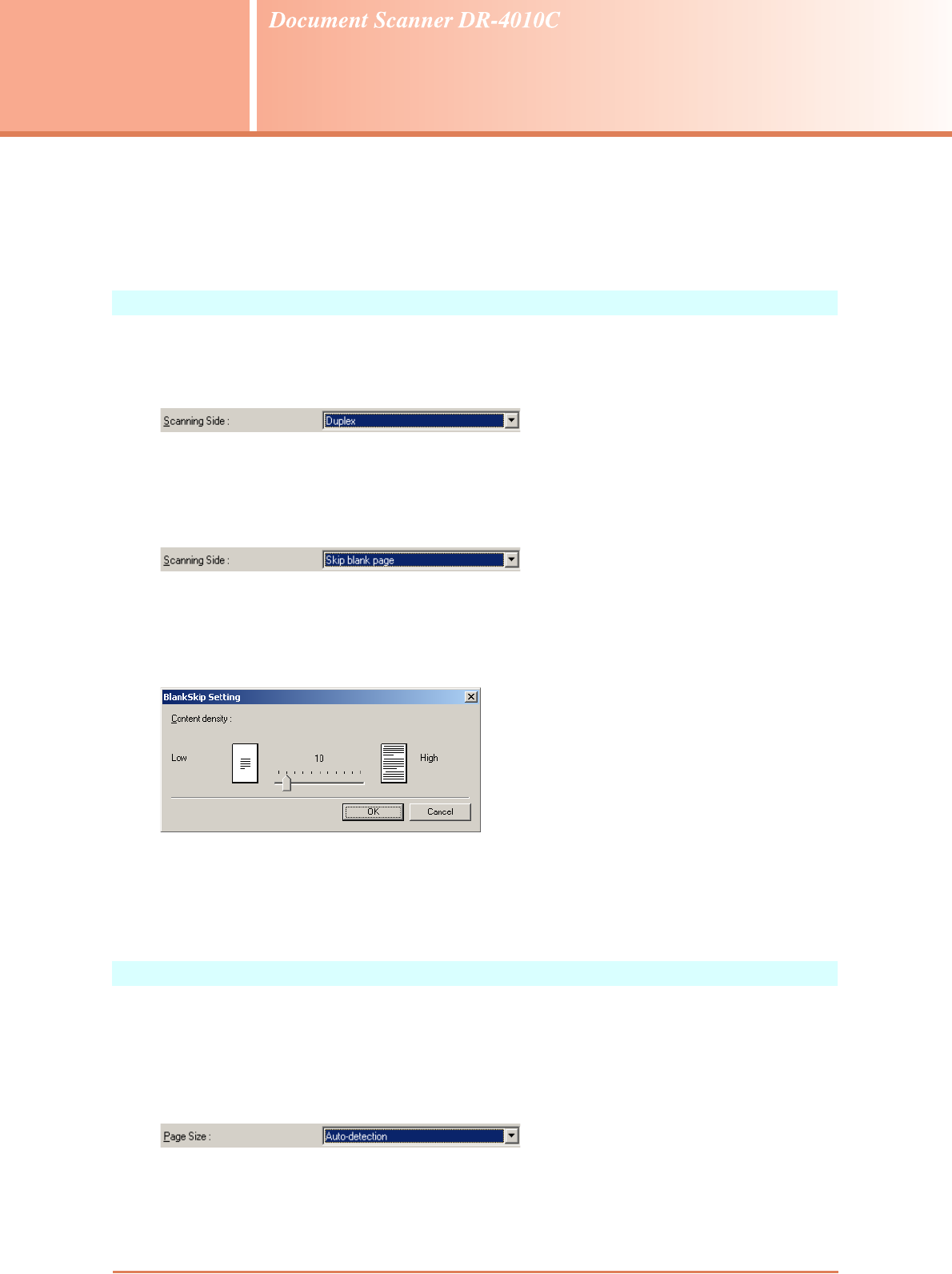
9-1
Chapter 9
Practical Examples
This chapter provides examples of settings for the DR-4010C ISIS/TWAIN driver. Refer to these
examples when making ISIS/TWAIN driver settings. For descriptions of particular setting items, see
“ISIS/TWAIN Driver Settings,” on p. 7-1.
Scanning Both Sides of Pages
• To scanning both sides of pages
Select [Duplex] for the Scanning Side setting on the [Basic] tab sheet. (See “Scanning Side,” on
p. 7-8.)
• To avoid scanning blank pages, such as pages at the back of a document
Select [Skip blank page] for the Scanning Side setting on the [Basic] tab sheet. Duplex scanning
is performed, and pages images detected as blank are not saved. (See “Scanning Side,” on p. 7-
8.)
• If blank pages are not skipped, even when [Skip blank page] is selected
Increase the [Content density] in the [Blank Skip Setting] dialog box. If the [Content density] is set
too low for documents with a light background, they may not be detected as blank pages, and not
be skipped. (See “Scanning Side,” on p. 7-8.)
• If documents with text are skipped as blank pages
Decrease the [Content density] in the [Blank Skip Setting] dialog box. If the [Content density] is
set too high for documents with little text, they may be incorrectly detected as blank pages, and
be skipped. (See “Scanning Side,” on p. 7-8.)
Scanning Non-Standard-Size Documents
• To scan non-standard-size documents
If non-standard-size documents are scanned with a standard size selected for the Page Size
setting on the [Basic] tab sheet, black regions may appear around the scanned document image.
To scan non-standard-size documents, select [Auto-detection] as the [Page Size]. Page size is
then detected automatically. (See “Page Size,” on p. 7-7.)
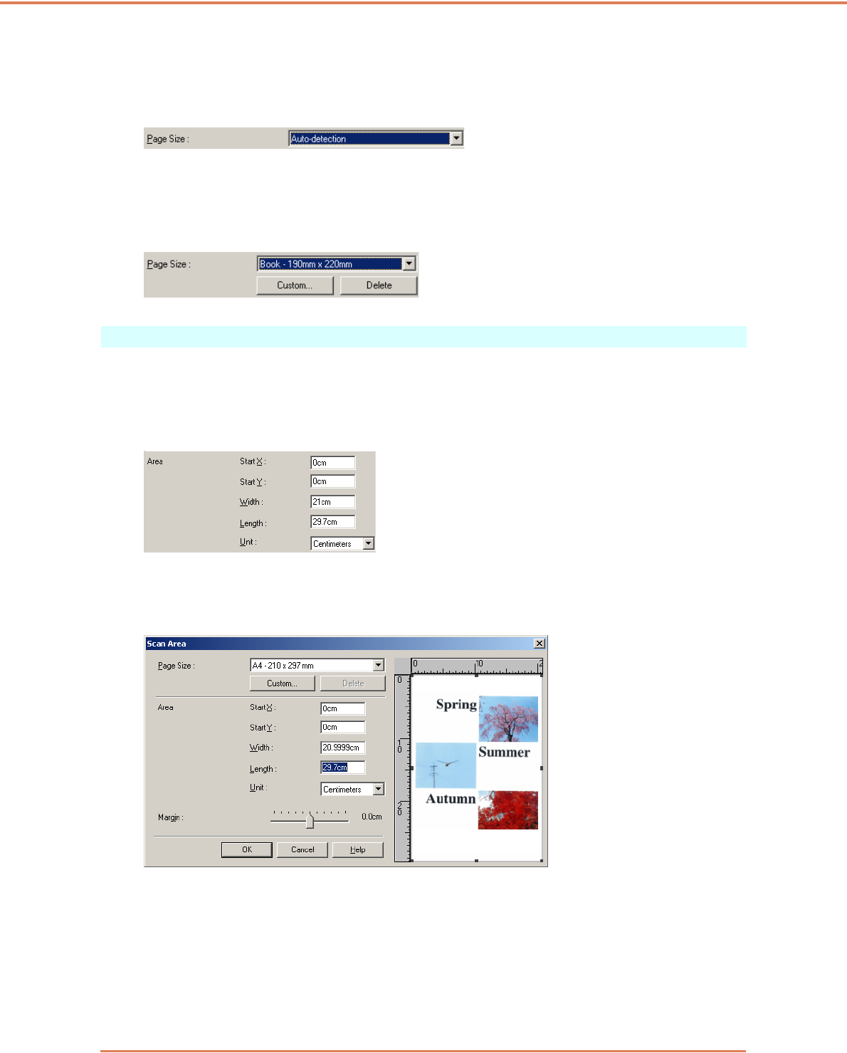
Chapter 9 Practical Examples
9-2
• To scan long-page documents
Set the scanning mode to Long Document mode, and select [Auto-detection] as the [Page Size]
in the Properties dialog box. Document pages may be up to one meter long.
(See “Long Document Mode,” on p. 3-30, and “Page Size,” on p. 7-7)
• To register a non-standard page size
A non-standard page size not already registered as a page size selection can be saved as a
custom page size by selecting the [Custom] button in the Scan Area dialog box. (See “User
Preferences,” on p. 7-5.)
Adjusting the Scan Area
• To scan only part of the document page.
You can specify any area on the page in the Scan Area dialog box. However, scan area settings
are ignored when [Auto-detection] is selected as the [Page Size]. (See “[Scan Area] Dialog Box,”
on p. 7-11.)
With the TWAIN driver, load a document in the scanner and click the [Preview] button to scan one
page.) The scanned image is displayed in the Area window so that you can adjust the scan area
while viewing the preview image. (See “Preview Button (TWAIN driver only),” on p. 7-13.)
With CapturePerfect, the last scanned image appears in the Area window. After executing [Scan
Single Page], open the Scan Area dialog box to view the scanned image in the Area window,
where you can set the scan area while viewing the preview image.
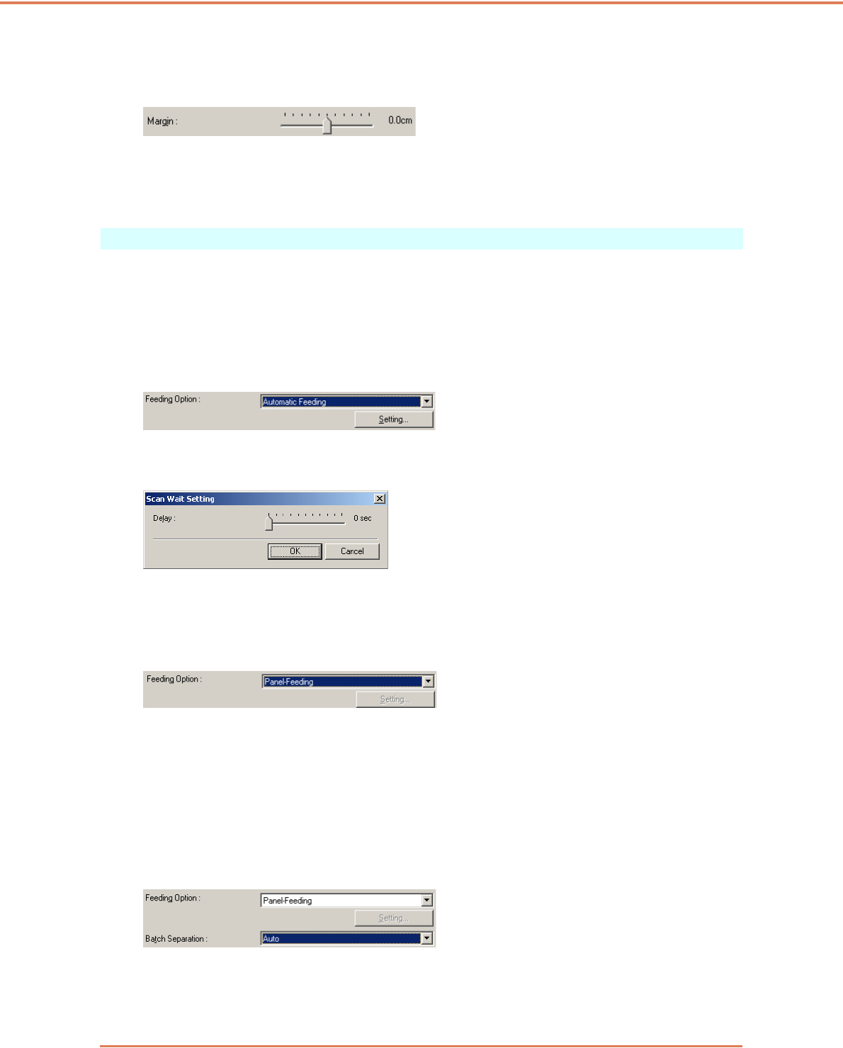
Chapter 9 Practical Examples
9-3
• To avoid losing the edges of an image due to shifting of the document page, or to remove
black frames from around images
Adjust the scan area using the [Margin] slider in the Scan Area dialog box.
If the edges are missing from the image, move the slider to the right to expand the scanning area.
Alternatively, to eliminate the black frame around scanned images, move the slider to the left to
reduce the scanning area.
Scanning Multiple Documents
• To scan a document that cannot be loaded all at once as multiple separate batches
Set the [Feeding Option] on the [Basic] tab sheet to either [Automatic Feeding] or [Panel
Feeding]. (See “Feeding Option,” on p. 7-21.)
When [Automatic Feeding] is selected as the [Feeding Option], the scanner detects documents
and starts scanning as they are loaded, so continuous scanning is available just by loading the
document batches repeatedly.
The [Setting] button allows setting a delay time from when a document is loaded until scanning
starts.
Set a delay time when you need to adjust the document guides or align the pages after loading a
document with automatic feeding.
When [Panel Feeding] is selected as the [Feeding Option], scanning does not start until you
press the Start button.
After loading different-size documents, adjust the document guides or sort the pages before
pressing the Start button to start scanning.
• To create separate files for each batch of documents during continuous scanning (ISIS
driver only.)
Set the [Feeding Option] on the [Basic] tab sheet to either [Automatic Feeding] or [Panel
Feeding], and set [Batch Separation] to [Auto]. Each batch of documents is saved with different
file names. (See “Batch Separation (ISIS driver only),” on p. 7-21.)
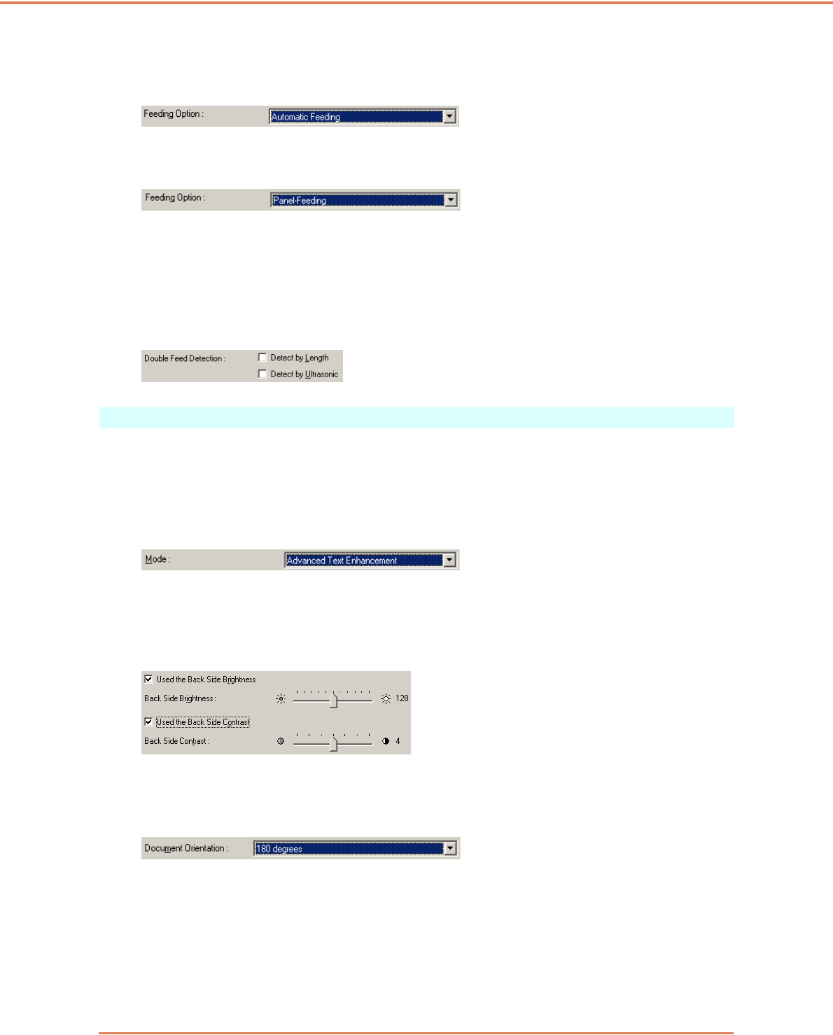
Chapter 9 Practical Examples
9-4
• To scan a batch of documents one page at a time
Set the [Feeding Option] to either [Automatic Feeding] or [Panel Feeding], and scan each page.
After scanning each page, the scanner returns to the waiting state.
When [Automatic Feeding] is selected as the [Feeding Option], the scanner detects documents
and starts scanning as they are loaded.
When [Panel Feeding] is selected as the [Feeding Option], press the Start button to scan after
loading each page.
• To stop the scanner when pages double feed
Confirm that the [Double Feed Detection] method selected on the [Others] tab sheet suits the
document being scanned. (See “Double Feed Detection,” on p. 7-21.)
Image Adjustments for Scanning
• To enhance text in documents with a background (when scanning in black and white
(binary) mode.)
Select [Advanced Text Enhancement] as the Mode on the [Basic] tab sheet. The background
behind the text is removed or processed so that the text is emphasized for better legibility. (See
“Mode,” on p. 7-5.)
• To scan documents with different brightness on the front and back
Adjust the back side brightness and contrast on the [Brightness] tab sheet. However, when a text
enhancement mode is selected, the back side brightness cannot be adjusted. (See “[Brightness]
Tab Sheet,” on p. 7-13.)
• To rotate scanned images
Select a rotation angle (0, 90, 180 or 270 degrees) as the Document Orientation setting on the
[Image processing] tab sheet. (See “[Document Orientation],” on p. 7-17.)
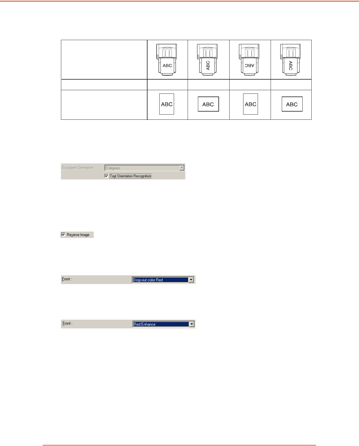
Chapter 9 Practical Examples
9-5
Scanned images are rotated as follows according to the orientation of loaded documents and the
selected angle.
• To rotate images to match document text
Select [Text Orientation Recognition] on the [Image processing] tab sheet. The text orientation on
each page is detected, and the scanned image is rotated in 90-degree increments as needed for
normalization.
When [Text Orientation Recognition] is selected, image rotation is disabled.
• To reverse black and white in scanned images (TWAIN driver only)
Select [Reverse Image] on the [Image processing] tab sheet. Black and white are reversed in
scanned images. (See “[Reverse Image] Check Box (TWAIN driver only),” on p. 7-18.)
• To ignore a particular color when scanning
Select a color to be ignored (dropped out) in [Color drop-out] on the [Image processing] tab
sheet, and that color will be eliminated from scanned images. (See “Color Drop-Out,” on p. 7-18.)
• To enhance a particular color when scanning
Select the color to be enhanced in [Color drop-out] on the [Image processing] tab sheet, and that
color will be enhanced in scanned images. (See “Color Drop-Out,” on p. 7-18.)
Feeder documents:
face up
Flatbed documents:
face down
Image rotation (clockwise) 0° 90° 180° 270°
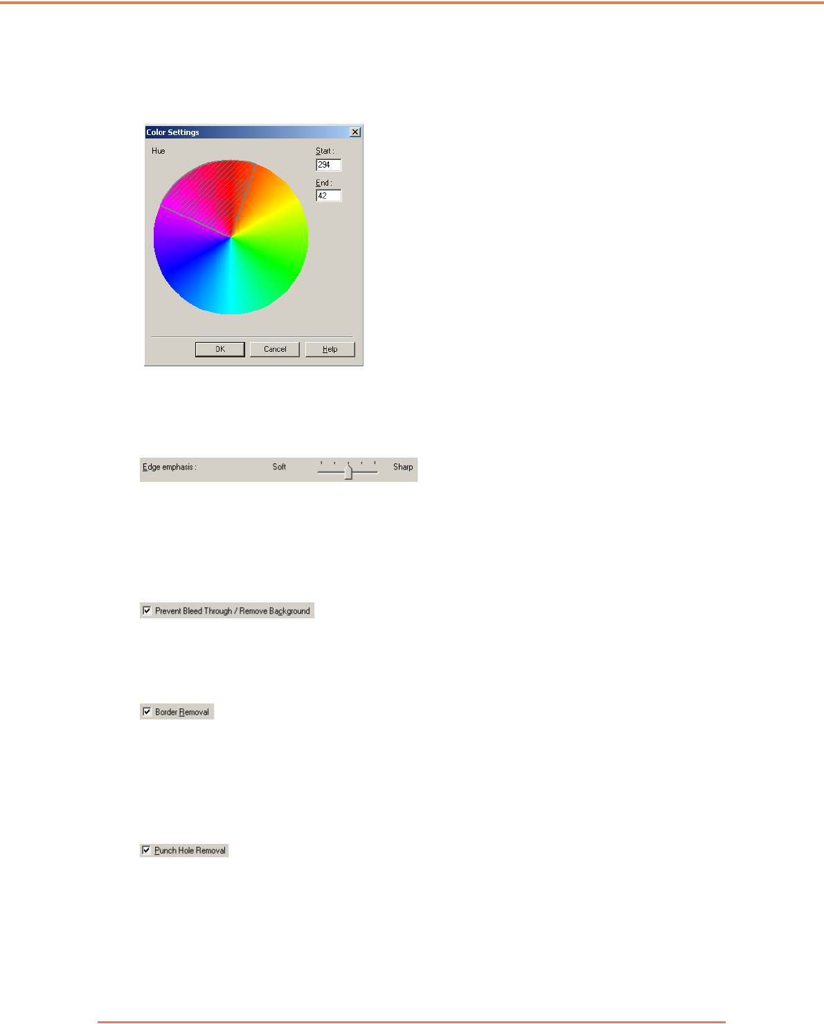
Chapter 9 Practical Examples
9-6
• To skip or enhance a custom color
Select [Drop-out color Custom] or [Custom color Enhance] in the [Color drop-out] list on the
[Image processing] tab sheet to open the [Color Settings] dialog box. Here you can specify the
range of colors to be dropped out or enhanced. (See “Color Drop-Out,” on p. 7-18.)
• To enhance contours in images
Adjust the [Edge Emphasis] setting on the [Image processing] tab sheet. (See “[Edge
Emphasis],” on p. 7-17.)
• To Prevent Bleed Through of text from the back side of thin document pages, or to remove
the background from scanned images
Select [Prevent Bleed Through / Remove Background] on the [Image processing] tab sheet.
Bleed-through on thin paper and backgrounds are removed from scanned images. (See
“[Prevent Bleed Through / Remove Background] Check Box,” on p. 7-18.)
• To remove black areas around images
Select the [Border Removal] check box on the [Image processing] tab sheet. The black areas
around images are removed. (See “[Border Removal] Check Box,” on p. 7-18.)
• To remove the black spots from scanned images when scanning documents with punch
holes
Select the [Punch Hole Removal] check box on the [Image processing] tab sheet. The black
spots from punch holes in documents are removed from scanned images. (See “[Punch Hole
Removal] Check Box,” on p. 7-18.)
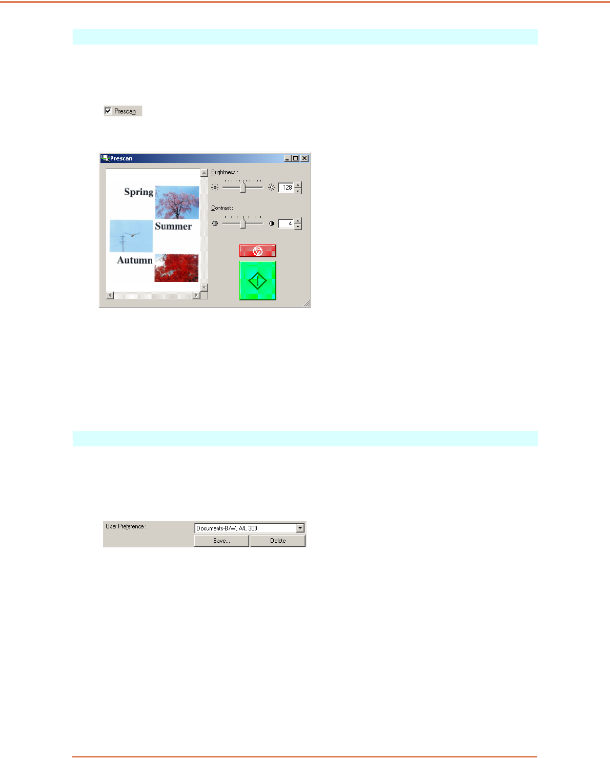
Chapter 9 Practical Examples
9-7
Prescan
• To confirm images before scanning
Select the [Prescan] check box on the [Others] tab sheet, and scan. When scanning is first
started, the first document page is prescanned and displayed in the Prescan panel.
• About the Prescan Panel
The Prescan window provides adjustments for image brightness and contrast of the first
document page before continuing scanning.
The image displayed in the prescan panel can be magnified for confirmation (with the mouse
over the preview image, left click to magnify, and right click to reduce.)
Brightness and contrast adjustments are reflected in the prescan panel image. After confirming
the image, click the Start button to resume scanning with the adjusted settings. Click the Stop
button to stop scanning.
Preserving Your Settings
• To preserve your settings for future use
Register a name for your settings as [User Preference] on the [Basic] tab sheet. When you want
to recall your settings later, select the name of your registered user preferences, and they will be
reflected in the tab sheets.

© CANON ELECTRONICS INC. 2006
CANON ELECTRONICS INC.
1248, SHIMOKAGEMORI, CHICHIBU-SHI, SAITAMA 369-1892, JAPAN
CANON U.S.A. INC.
ONE CANON PLAZA, LAKE SUCCESS, N.Y. 11042, U.S.A.
CANON CANADA INC.
6390 DIXIE ROAD, MISSISSAUGA, ONTARIO L5T 1P7, CANADA
CANON EUROPA N.V.
BOVENKERKERWEG 59-61, P.O.BOX 2262, 1180 EG AMSTELVEEN, THE NETHERLANDS
CANON LATIN AMERICA, INC.
703 WATERFORD WAY, SUITE 400 MIAMI, FLORIDA 33126, U.S.A.
CANON AUSTRALIA PTY. LTD.
1 THOMAS HOLT DRIVE, NORTH RYDE, SYDNEY. N.S.W, 2113. AUSTRALIA
CANON SINGAPORE PTE. LTD.
1 HARBOUR FRONT AVENUE #04-01, KEPPEL BAY TOWER, SINGAPORE 098632
CANON HONGKONG COMPANY LTD.
19TH FLOOR, THE METROPOLIS TOWER, 10 METROPOLIS DRIVE, HUNGHOM, KOWLOON, HONG KONG.
