Canon F 1 New Service Manual F1N Repair
F-1 New - Service Manual New_F1_SM Free User Guide for Canon IXUS Series Camera, Manual - page3
2015-08-11
: Canon Canon-F-1-New-Service-Manual-783752 canon-f-1-new-service-manual-783752 canon pdf
Open the PDF directly: View PDF ![]() .
.
Page Count: 125 [warning: Documents this large are best viewed by clicking the View PDF Link!]

Canon NEW F-1 Service manual
Page 1
CANON NEW F-1
SERVICE MANUAL
EXPLODED VIEWS
AND
PARTS LIST
CANON INC. JAPAN
Canon NEW F-1 Service manual
Page 2
Contents
1. SWITCH POSITION AND NOMENCLATURE............................................................................................... 4
2. COVERS ................................................................................................................................................................ 6
3. FRONT PANEL UNIT ATTACHMENT AND REMOVAL .......................................................................... 10
4. FRONT BODY .................................................................................................................................................... 12
5. UPPER BODY (WINDING SIDE)..................................................................................................................... 16
6. TUNGSTEN CABLE ADJUSTMENT.............................................................................................................. 19
7. SPOOL ................................................................................................................................................................. 20
8. SPROCKET ......................................................................................................................................................... 22
9. CHECKS AND ADJUSTMENTS...................................................................................................................... 23
10. UPPER BODY (REWIND SIDE)................................................................................................................... 31
11. LOWER BODY (I) .......................................................................................................................................... 34
12. LOWER BODY LUBRICATION.................................................................................................................. 38
13. LOWER BODY (II) ........................................................................................................................................ 39
14. ELECTRICAL ADJUSTMENTS .................................................................................................................. 42
15. FRONT PANEL UNIT ASSEMBLY AND DISASSEMBLY...................................................................... 50
16. EYE LEVEL FINDER.................................................................................................................................... 61
17. MOISTURE RESISTANT TREATMENT ................................................................................................... 66
18. WATER RESISTANT TREATMENT.......................................................................................................... 68
19. SHUTTER SPEED VARIATIONS................................................................................................................ 70
20. SERVICE TOOLS LIST................................................................................................................................. 71
21. TROUBLESHOOTING CHARTS ................................................................................................................ 74
22. PARTS LISTS.................................................................................................................................................. 89
Canon NEW F-1 Service manual
Page 3
Introduction
The NEW F-1 is the base of a completely new Integrated Functional System. It is based on
the original F-1 but utilizing many advances in electronics, precision machining and precision
optics made since the original F-1 was developed ten years ago.
The following considerations should be kept in mind when repairing the New F-1:
1. To maintain complete interchangeability between the camera body and the system
accessories, repair personnel must understand the interfaces (mechanical
and electronic) between the body and accessories. They must also be familiar with
repair standards, checking, adjustment and tools maintenance procedures.
2. Preventive maintenance (lubrication, adjustment and parts replacement) are
necessary to insure the reliability of the NEW F-1.
Special Repair Instructions
1. Many of the electrical contacts in the camera are molded into plastic insulators.
When making solder connections, the soldering time should be kept as short as
possible.
2. 3% silver solder should be used to solder the IC's.
3. Many bearing balls are used in the winding mechanism. Be careful during assembly
and disassembly to insure that no balls get lost in surrounding mechanisms.
4. When the rewind crank is not installed, if the rewind shaft is pushed down past a
certain point it becomes impossible to open the back cover without removing
certain parts that normally need not be removed. This results in lost time.
5. Be sure that the elastic connectors used to connect the flexible and rigid circuit
boards are kept clean and free of contamination.
6. The water and moisture proofing complicates many repair procedures. Take care
that they are correctly performed
7. If the tungsten cable is kinked or frayed, repair is difficult and time-consuming. It is
much more cost efficient to be careful to not damage the cable than to repair or
replace it.
8. The correct adjustment of the AV AE shutter speed indicator output resistor (RM
TV2) and the TV AE aperture determination resistor (RAE) are basic to maintaining
system interchangeability.

Canon NEW F-1 Service manual
Page 4
1. Switch position and nomenclature
Name Operation
SW1 Metering Switch ON: Metering activated
SW2 Release Switch ON: Starts Release sequence
SW4 Count Switch OFF: Shutter exposure timing starts
SW5 Winding Complete Switch OFF: Winding complete
SW6 Stop-down (S.D.) Switch ON: Stopped-down (ganged with SWll1)
SW7 Self Timer Switch ON: Self timer activated
SW8 Battery Check Switch ON: Battery Check
SWll Lens A-M Switch. ON: Lens set to "a" mark
SW1l' Stop-down switch OFF: Lens stopped down
SW12 Bulb switch OFF: "Bulb" shutter speed
SW14 Timer Switch ON: Timer Activated
SW15 Lamp Switch ON: Viewfinder illumination on
SW16 X Sync Switch ON: 1st curtain open; OFF: Winding complete
SW16' Safety Switch ON: Mirror up; OFF: Mirror down
SW17 Film End Switch ON: No film on take-up spool
SW18 2nd Curtain Switch OFF: When 2nd curtain starts

Canon NEW F-1 Service manual
Page 5
1) SW12 and SW18 Relationship
2) SW16 and SW16' Relationship
1st curtain
X contact must turn off after the 2nd curtain
closes and before winding is complete.
3) SW11, SW6 and SW11’ Relationship
Lens "A"
Lens "M"
Max.
S.D.
Max.
S.D.
SW11
ON OFF
SW6,1
1'
ON OFF ON OFF
Max: Open aperture S.D.:
Stopped down

Canon NEW F-1 Service manual
Page 6
2. Covers
Numbers 1-37

Canon NEW F-1 Service manual
Page 7
Disassembly Notes Assembly and Adjustment Notes
1. Remove the smooth face screw (3)
and shutter button (6) with tool
(CY9-6131-000).
2. Be careful not to lose detent
ball (7)-2 inside the camera.
3. The shutter dial cap (9) is glued in place.
4. Seals (8)(14)(29) and (30) are
available in more than one thick
ness to insure correct sealing.
5. When the rewind crank (22) is not
installed, don't push the rewind
shaft all the way down into its
holder. (If it is, time will be
lost in unnecessary work, because
of the click spring.)
6. Press the opening safety stopper
while removing the left top cover
7. (35).
Assembly and Adjustment Notes
1. Put Diabond into the winding
lever shaft hole before final
installation of the screw (3).
2. Lubricate the shutter button
shaft (6) and the interior or
the release lock (7) with GE-C9
[See Water-resistant treatment
(XIX)].
3. Put Lozoid in the detent groove
of the release lock (7).
4. Place teflon washer (8) under the lock lever
(7). Use a washer that is 0.3mm thicker than
the "A" dimension shown below. (Water
resistance)
A = l.l-(a-b) mm
Washer t = A +0.3mm
5. The teflon washer (14) used under the shutter
dial should be 0.1mm thicker than the "B"
dimension shown below. (Water resistance)
B .= 0.5-(a-b)
Washer t = B +0.1mm
6. When installing the shutter dial, align the notch
in (15) and the pin in the shutter dial ring (13)
with the hole in the top cover. The shutter
must be set to "A" before the dial is installed.
Note: Numbers in parentheses in the text correspond to circled
numbers one page 6. Disassemble in normal order and reassemble in
reverse order.

Canon NEW F-1 Service manual
Page 8
Assembly and Adjustment Notes
7. Adjust the rewind crank (22) slip torque by changing the friction washer (21).
Torque Limits: 35 to 55 gcm.
8. Lubricate both sides of friction spring (20) with PL-015.
9. Hold the rewind fork. Raise the rewind crank knob and turn in
the rewind direction. The clutch should engage within one half
turn,
10. To install the ASA Dial, set the SV wiper wiper pin as shown and align the "1/2"
on the exposure compensation dial with the index.
11. Check the difference in height between the rewind crank bushing and the "A"
and "B" surfaces. Install a slightly thinner washer as indicated below.
11.1. Washer (30) "A" Difference Check at four points.
Ex: Difference Washer "t"
0.15mm --- 0.1mm
0.2mm --- 0.2mm
0.1mm --- No washer
11.2. Washer (29) “B” Difference
Ex: Difference Wacher “t”
0.55mm --- 0.5mm
0.4mm --- 0.4mm
0.35mm --- No washer
Note: Numbers in parentheses in the text correspond to circled numbers
on page 6. Disassemble in normal order and reassemble in reverse
order.

Canon NEW F-1 Service manual
Page 9
Assembly and Adjustment Notes
12.
SV Brush Adjustment
12.1.
Set the SV (ASA.) dial to ASA 6400 -1/3.
12.2.
Set the exposure compensation dial at "1".
12.3.
Check the position of the brush through the P.C. terminal hole.
Note: Shining the light source (a penlight or the illuminator D or M) through the
loupe makes the brush position easier to see.
12.4. Look at the underside of the SV board to check if the brush
if the brush is positioned as shown on the ASA 6400 -1/3 pad.
Note: It must stay on the pad at both extremes of dial play.
12.5. Set the dial to ASA 6400 and check that the meter doesn't
vary suddenly either up or down.
12.6. If the adjustment is not correct adjust the SV board eccentric.
13. After installing the top cover (35), check the operation of the NORMAL-TIMER-LAMP
switch.
It should switch from one function to the next as shown.

Canon NEW F-1 Service manual
Page 10
3. Front panel unit attachment and removal
Disassembly Notes
To remove the front panel unit, remove the
following parts.
1 Remove the top covers, mount
apron and bottom cover.
2 Body coverings (front)
3 Beeper plate
4 Removing the Mg2 latch lever
makes the AE joint gear easier
to remove.
5 AE Joint Gear
Position the main diaphragm lever so the
gear can be removed.
6 Tripod Socket
7 Diaphragm Stricker lever
8 Battery Chamber Cover
9 Pentaprism rails
10 Unsolder eleven leads to main
circuit board.
11 X sync contact yellow cord
12 Battery Check contact
Assembly and Adjustment Notes
1 AE Joint Gear and AE Coupler
Installation
1.1 Lubricate the joint gear and
coupler shafts with Astro-Oil-
MIL-G.
1.2 Align the raised portion of
the coupler gear with the
mounting screw as shown.
1.3 Align the mark on the joint
gear with the positioning
hole as shown.
2 Front Panel Unit Installation
2.1 Lubricate the marked parts of the
mirror charge and signal levers (in the
body) with Lozoid.
2.2 Wind until the curtain edge is
approximately in the center of
the frame.
2.3 In this semi-wound condition,
do not move the signal lever
(Fig. 1) or Intermediate signal
lever (Fig. 4, next page).
Note: Numbers in parentheses in the text correspond to circled
numbers on page 6. Disassemble in normal order and reassemble in
reverse order.

Canon NEW F-1 Service manual
Page 11
Disassembly Notes
13. If the SV board is to be removed,
remove the white cord from the P.C.
Terminal.
If the SV board is not going to be
removed, lift the front panel and
unsolder to white cord from the front
panel (SW16’) end.
14. Remove the plastic foam light shields
from the battery box area.
15. If the moisture seal rubber around the
main circuit board is damaged, replace
it.
Assembly and Adjustment Notes
2.4 In the order shown in figure 2, set the
levers as shown in figure 3.
Fig. 2 Fig. 3
3.1. With the levers positioned as in figure
3, install so they are between the mirror
charge and signal levers (Fig. 1. page
6).
Caution: If this operation is not done
correctly, winding timing will
be incorrect and the shutter
will not cock.
3.2. While performing the above step, it is
possible that the signal lever will get
pushed out of position. Check that the
levers are positioned as shown below.
(Another method is to hold the
intermediate signal lever toward the
mount side while installing the unit.)
3.3. While holding the body 1st curtain
latch lever out of the way, position the
1st curtain start lever toward the rear.
3.4. Put Arontite R on the threads of the
mirror striker lever screw before
installing it.
Note: Numbers in parentheses in the text correspond to circled numbers on page 6.

Canon NEW F-1 Service manual
Page 12
4. Front body
Numbers 1-16

Canon NEW F-1 Service manual
Page 13
Disassembly Notes
1. To remove the main circuit board (6), the
lower body flex must be moved slightly.
2. When the battery cover is removed,
temporarily replace the earth (grounding)
screw.
Assembly and Adjustment Notes
1. Apply electrolub to the connector portions
of the main circuit board (6) and lower
body flex.
2. Clean the elastic connectors (2) and (7)
with electrolub.
3. Install cushion II (4) as shown below.
Assembly and Adjustment Notes
4. Clean the connector portions of the resistor
board (R Board) (9) and main circuit board
(6) (rear side) and apply electrolub.
5. Install the resistor board (9) into the body.
Put diabond on the rear of the board
around the mounting holes.
6. Battery Chamber Unit (10) Post
Installation Checks
6.1. Without a battery installed, the
swinging release rod (p/6 the battery
chamber unit) must overlap the
release pin below it by at least 1/2 the
pin diameter.
6.2. When the minus contact of the
battery box is pressed down and then
released slowly, the
rod must return completely and
smoothly.
7. Install cushion I (11) as shown below.
Push it in until it is flush against the main
circuit board and diabond it to the body.
Note: Numbers in parentheses in the text correspond to circled numbers on
page 12. Disassemble in normal order and reassemble in reverse order.

Canon NEW F-1 Service manual
Page 14
Assembly and Adjustment Notes
8. Attach the light shield (12) and seal (13) as shown.
9. Pentaprism Contact Installation
9.1. Don't interchange the
position of the left and right
contacts, or reverse either of
them.
9.2. Solder the leads as quickly
as possible. Excessive heat will
loosen the contact pins.
10. Main Flex Installation
10.1. Solder the main flex (16) at the following positions.
10.2. To prevent the main flex from interfering with the top cover screw holes, fix it with
double-sided tape.
10.3. The brown leads to SW12 are interchangeable.
See section 9 (Upper Body)
for the correct bending of
the flex.
Note: Numbers in parentheses in the text correspond to circled numbers
on page 12. Disassemble in normal order and reassemble in reverse order.

Canon NEW F-1 Service manual
Page 15
Assembly and Adjustment Notes
11. Front Panel Lead Soldering
11.1. Put flux on the main circuit board solder lands.
11.2. Solder from the bottom up.
11.3. Dress extra lead toward the bottom as shown.
Note: The thick white lead goes to the
P.C. terminal.
Note: Numbers in parentheses in the text correspond to circled numbers on page 12.
Disassemble in normal order and reassemble in reverse order.

Canon NEW F-1 Service manual
Page 16
5. Upper Body (Winding side)
(6) can be displaced without removing (1) - (5)

Canon NEW F-1 Service manual
Page 17
Disassembly Note
1. Shutter Speed Selector
1.1. To remove the shutter speed selector
(6), unsolder the black lead from SW4
and remove four screws [(6)-1 x 2 and
(6)-2 x 2].
Notes:
1. One of the (6)-1 screws is partially
hidden by flex (5) and hard to remove.
2. Be careful not to damage the main flex.
1.2 To remove the selector (6) completely,
unsolder the black and brown leads and
disengage the tungsten cable.
1.3 To temporarily remove (6) without
removing the tungsten cable:
1) Set the shutter to the "B" position and
remove the screws. Carefully lift the
selector off.
2) Place the selector out of the way but
where the cable will remain taut and
not become kinked.
2. Mounting screw (9)-2 for the winding
base is under main switch (8).
3. The entire 2nd curtain brake assembly
(17) can be removed without
disassembling it by removing three
screws (15) and collar (16). Disengage
the brake lever from the
master gear and (17) can be removed.
Assembly and Adjustment Notes
1. The shutter speed selector (6) TV double
brushes must be aligned both vertically
and radially, so they will both make
contact with the correct pad.
2. Clean the TV resistor board (2) and install
it so that break in the pattern is at the
upper right with the shutter at "A".
Pattern break
3. Shutter Speed Selector (6)
3.1 Installation
1) Lubricate the (Upper) Rewind button lock-
out lever with Lozoid 72090.
3.2 Post-Installation Checks
1) Check that the see-saw lever works
smoothly.
2) There should be less than 0.2mm
difference in the height of the fixed cam
and see-saw lever.

Canon NEW F-1 Service manual
Page 18
Assembly and Adjustinent Notes
4. Winding Unit (9) Installation
4.1. Lubricate the winding coupler
joint with MIL-G.
4.2. Lubricate the friction surfaces
of the idler gear and frame
counter drive claw with Lozoid
72090.
4.3. Install with the frame counter drive claw pulled out of the way.
5. Put a little Arontite L in the Key screw (10) hole in the sprocket shaft (12) and install the
screw.
6. 2nd Curtain Cam Follower (13)-3 Installation
6.1. In the wound condition, the gap between the 2nd Curtain Cam Follower and the
hook should be 0.05 to 0.15mm. Adjustment: The follower is available in several
sizes.
6.2. Lubricate the pivot shaft with astro-oil.
6.3. The end play of the follower should be less
than 0.15mm, and it must return by the spring
pressure.
6.4. The mesh of the follower and the hook should
be 0.2 to 0.3mm. Adjustment: Eccentric
6.5. Lubricate the mesh surfaces of the follower
and hook with astro-oil.
7. 2nd Curtain Release Lever
7.1. Lubricate the shaft with astro-oil.
7.2. Thrust play should be under 0.05mm and end play under 0.2mm. Use washers to
adjust the play.
8. 2nd Curtain Brake Assembly (17)
8.1. While holding the brake lever out of the way (toward the prism rails), slip the
brake assembly (17) into place under the master gear.
8.2. Tighten the screws starting with the one at the front (mount) side.
Note: Numbers in parentheses in the text correspond to circled numbers on page 16.
Disassemble in normal order and reassemble in reverse order.

Canon NEW F-1 Service manual
Page 19
6. Tungsten cable adjustment
Assembly and Adjustment Notes
1. Put the knotted end of the cable into the slot in the indicator pulley. Charge the
pulley one revolution and temporarily install a pin to hold it.
2. Check that the cable lies correctly in the pulley.
3. Set the shutter dial at "B". Information
pulley
4. Thread the cable as shown in figure 1.
5. Remove the pin from the indicator pulley and find the spot
where the "B" appears in the finder. Temporarily fix the end as shown in figure 2.
At the point on the shutter dial pulley where the slot is a very small knot must now
be formed.
6. Tie the knot as shown below.
7. Insert the knot into the slot.
8. Put cyanobond on the knot slot. Do not get bond on the cable or in the pulley
groove.
9. Check the entire range of shutter speeds. If they are not correctly aligned in the
information window, adjust the nut on, the information pulley vertically until they
are. After adjustment, stake the nut with black diabond.
10. Check that the right-side viewfinder information disappears when the dial is moved
from 1/2000 to "A".
Check that the right-side viewfinder information appears when the dial is moved
from "A" to 1/2000 and remains visible through the entire shutter-speed range
from 1/2000 to "B".

Canon NEW F-1 Service manual
Page 20
7. Spool
Steel Balls 3,5,7,9 Lozoid 72090

Canon NEW F-1 Service manual
Page 21
Disassembly Notes
Be careful not to loose any of the bearing balls inside the camera. (See the facing
page for the number of balls in each location.)
Assembly and adjustment
1. Winding Coupler (4)
1.1 With the shutter completely wound {winding stopper engaged) , the winding
coupler should be positioned as shown (10° ± 4.5° off the body centerline).
1.2 Visual angle check: the: line formed by the axis of the winding shaft and the
mounting screw for SW5 is the maximum limit (14.5°) for the coupler.
2. Spool Torque
2.1 Lubricate the spool unit fiber friction washers with a mixture of FLA and PO A2
grease. (7:3)
2.2 Exercise the spool mechanism 30 to 50 times. Then measure the torque.
Std: 110 - 150 gcm
3. Post Assembly Checks
3.1 After the spool unit is installed in the camera the correct tension measured at
the spool circumference (equivalent to spool friction torque) 170 to 230g.
3.2 Adjust the thrust play to 0.1 to 0.3mm by changing washer (15).
4. Adjust winding shaft thrust play to 0.05 to 0.15mm by changing washer (2).
Note: Numbers in parentheses in the text correspond to circled numbers on page 20.
Disassemble in normal order and reassemble in reverse order.

Canon NEW F-1 Service manual
Page 22
8. Sprocket
Lozoid: Loroid 72090
Assembly and adjustment notes
1. Lubricate the upper and lower
sprocket bushings with PL-015.
2. Adjust thrust play to 0.1 to
0.2mmm with washer (8).
3. Align the toothless section of the
main gear with the stopper notch
in the sprocket shaft (3)
4. Adjust thrust play of the main gear
to 0.03 to 0.15mm by-
washer (4).
5. Align the main gear (2) and idler
gear (12) as shown below and
mesh them.
The protuding striker section should be as
shown ±2 teeth.

Canon NEW F-1 Service manual
Page 23
9. Checks and adjustments
Assembly and Adjustment Notes
1. Shutter Curtains Installation
1.1. In the wound condition, the leading edge of the 2nd curtain should be from 5.4 to
5.9mm from the edge of the film aperture.
1.2. The leading edge should be parallel with the edge within 0.2mm.
1.3. In the wound condition, the trailing edge of the 1st curtain should overlap the
leading edge of the 2nd curtain by 2.0 to 2.5mm, and this overlap should be
maintained throughout the winding cycle.
1.4. The edge of the 1st curtain should be parallel with the edge of the 2nd curtain
within 0.2mm.
Note: The 2nd curtain "minus latch" should not latched at the full wound (5.4 -
5.9mm) position.
2. 1st Curtain Brake
2.1. Check
1) From the maximum curtain travel position* to the fully wound condition, the ratchet
should move from the start position to the middle of the third tooth.
2) Even if the brake lever is pushed in the direction to the
end of its travel the ratchet should not go to the 4th tooth,
* Maximum curtain travel position: The curtains usually stop slightly short of this position
because of the brakes. For accurate checks, they can be pushed to the maximum with the
master gear.

Canon NEW F-1 Service manual
Page 24
Assembly and Adjustment Notes
2.2. 1st Curtain Brake Adjustment
From the maximum curtain travel position, wind, release the shutter with the
seesaw lever at "B", and check the difference in the position where the curtain
stops and the maximum curtain travel position. It should be no more than half-
a-tooth on the master gear.
1) To increase brake torque, turn the nut CW, but don't overtighten it. When you
reach the point where it starts to get tight, back off 90°.
2) To veaken torque, turn the nut CCW, but don't turn it too far. It should not be high
enough to touch the cam follower at the maximum follower play.
3) If the adjustment cannot be made with the nut, three different diameters
(strengths) of the coil spring are available (0.6, 0.65 and 0.7mm dia.).
4) After adjustment apply diabond to the nut. Do not use enough to increase the
height of the nut.
3. 2nd Curtain Brake
3.1 Adjustment
1) Standard: 0 to 0.5 teeth (master gear) Check as explained in 2.2 above.
The nut must not exceed the height of the shutter speed selector base.
2) Other adjustments are identical to the 1st curtain brake adjustment.
3.2 Brake Torque Check (Reference)
Measure the tension at the ratchet pawl as indicated.
1st Curatin Brake: About 2nd Curtain Brake
800g (with return spring disengaged)

Canon NEW F-1 Service manual
Page 25
Adjustment Notes
4. SW4 OFF Timing
4.1 Clean the contact surface with keton.
4.2 Slowly push the 1st curtain release lever
in the "A" direction and note where the
latch is released. Adjust the switch with
the eccentric so that SW4 goes off at 0.1
to 0.2mm additional travel.
4.3 The eccentric should be adjusted so that
longer side is toward the rear.
5. Dowel Gear Position
At the maximum curtain travel position, and with the
camera mount toward you, the dowel should be within
0.5 teeth left to 1 tooth right of the centerline.
6. SW5 Timing
6.1 Switching Position
At a point 0.8mm from the bottom of the
stopper notch on the engagement stroke
of the stopper claw, SW5 should switch on.
1) Make sure that the stopper is not
0.8mm
from the bottom of the disengagement
stroke.
2) Check the position of the drive pin.
It is different from engagement and
disengagement.
3) Do not forget to retighten the nut after
adjustment.
6.2 As a visual check of the SW5 brush position
the edge of the pattern should be located
approximately under the midpoint of the
slope "A" of the brush.
6.3 In the wound condition, SW5 must be off and
turn on during winding.
6.4 After the check is finished, stake the nut with diabond.

Canon NEW F-1 Service manual
Page 26
Adjustment Notes
7. Mechanical Release Stroke Adjustment
The shutter should release at 1.4±0.15mm of the
shutter button stroke. Adjust with the eccentric.
8. "Bulb" Pin Adjustment
Adjust so that at 1.25mm of the shutter button
stroke the
"bulb" pin and "bulb" lever are not touching.
9. Rewind Button Release Stroke Adjustment
9.1 Close the back cover. Set the rewind (R) button.
9.2 Adjust the eccentric so that the R button is released
at 1.0±(0.2mm of the shutter button stroke.
9.3 Check that the sprocket is free and turns smoothly
when the R button is set.
10. Following Needle Position
10.1 Mount the "tool standard" lens and set the diaphragm at
f/5.6.
10.2 Limit: A line "a" through the center of the following must fall
on the f/stop number (dimension "b"). The height of the
f/stop numbers is equal to 0.6 f/stops.
10.3 There must be approximately the width of the following
needle ring clearance between the outer edge of the
needle circle and the edge of the aperture scale make.
10.4 After adjustment, apply a small amount of cyanobond at
"c", "d" and "e".
10.5 Apply diabond to the root of the needle.

Canon NEW F-1 Service manual
Page 27
Adjustment Notes
11. Mechanical Shutter
11.1 Curtain Travel Time
1) Standard: 7.5±0.2ms (1/1000)(34mm slit spacing).
2) Adjustment: Spring Drum Gear
11.2 Shutter Speed (Exposure Time)
1) Adjust at 1/250 using the 2nd Curtain Release Lever (Seesaw Lever) Turning
the seesaw eccentric CW increases shutter speed.
2) Adjust 1/2000 with the 2nd curtain cam follower.
3) Adjust repeating steps 1 and 2 until the best balance of all
speeds is obtained.
4) Shutter Accuracy (measured in EV) Faster
1/2000, 1/1000: ±0.4EV
1/500 - 8 sec : ±0.2EV
12. Meter Position Adjustment
12.1 Connect a 10kohm variable resistor and microammeter in
series to the + side of the power supply set to about 2V.
Adjust the resistor for a current flow of 459uA through the
meter.
12.2 Adjust the meter housing position so that the meter needle
is centered on the "8" ±0.05mm.
12.3 Adjust the current and check the following positions:
12.4 Bond the meter housing to the die casting with black diabond. (Do not leave any
strings of bond.)
13. Battery Check and Low voltage Interlock1
13.1 Reduce the power supply voltage until the top of the
meter needle is about 0.1mm below the bottom of the
battery check index. At this point check that the
applied voltage is from 3.0 to 3.7 volts.
13.2 Check that the low voltage interlock activates at 3.2 volts.
Note: 1. Low voltage interlock is the voltage where shutter release is prevented by the
cameras program.

Canon NEW F-1 Service manual
Page 28
Adjustment Notes
14. Maximum Aperture (AVO) Indicator
14.1 Set AVO= 2.8 (Max. Aperture Pin Height =
6.9±0.03mm)
14.2 Bend the lever (dwg.) so that the top of the red
mark is positioned within the hatched area.
14.3 Check other maximum apertures. They should
also fall within 0.3 to 0.5f of the same position.
15. Aperture Mask Installation and Adjustment
15.1 The distance from the "A" surface to the
bottom of the mask opening is 2.42±0.03mm.
15.2 The distance from the "B" surface to the
bottom edge of the shutter speed opening is
2.70±0.03mm.
15.3 The distance from the C surface to the f/1.2
end of the aperture scale mask aperture is
16.2±0.1mm. When the mask is correctly
positioned, bond it with diabond.
15.4 To position the aperture scale film, install the
film with diabond, install the prism and position
the film before the bond hardens.
16. Frame Counter Adjustment
16.1 With the frame counter in the returned
position, the stop claw should be
engaged and flush against the 7th tooth
±0.1 Adjust with the eccentric.
16.2 Adjust the advance claw with the hex-head
eccentric so the tip of the claw is 0.3 to 0.6mm
up the slope of the 5th ratchet tooth.
16.3 When the advance claw is at maximum stroke,
adjust so that the clearance of the stop claw is
0.2 to 0.4mm.

Canon NEW F-1 Service manual
Page 29
Adjustment Notes
17. Following Needle Hidden Position
17.1 Activate the stop-down lever, with the lens on
or off of "A", the following needle must not be
visible.
17.2 Push the stop-down lever back into the normal
position. With the lens off of "A" the following
needle is visible. It must disappear when the
lens is set to "A".
17.3 Adjust the hex-head eccentric (dwg.) to meet
these requirements.
17.4 Following Needle Movement (Reference)
18. Release Stroke and Pressure (Checks)
18.1 Mechanical Release (without battery)
Shutter button protrusion : 1.0±0.2mm (Std: Shutter Ring)
Release Stroke : 1.4±0.2mm
Total Stroke : 1.7±0.1mm
Release pressure : Under 1,000 g
18.2 Electromagnetic Release
SW 1 ON : 0.8+0.2mm
SW 2 ON : 1.4±0.2mm
SW 1 - SW 2 Separation : At least 0.5mm
Total Stroke : 1.7±0.lmm
SW 1 Pressure : 100±20 q (except when R button
SW 2 Pressure : 350±50 g set or at "B")

Canon NEW F-1 Service manual
Page 30
Adjustment Notes
19. SW 18, X Sync Check and Adjustment
19.1 X Contact Check
When winding from the maximum
curtain travel position (MCTP), the
contact separation is 0.3mm when
the brake claw is on the third ratchet
tooth.
Also, when winding from the MCTP,
the contact drive dowel must have at
least 0.5mm total travel.
19.2 SW 18 Check and Adjustment
1) While winding slowly from the MCTP,
adjust so that SW 18 turns on when
the brake claw has traveled 2 to 2.5
teeth. Adjust by bending the fixed
contact.
2) (Visual Check)
With the brake claw at the third
tooth, check that there is at least
0.2mm separation between the drive
pin and the switch lever.
3) Apply TUFFY TF-1156 to the marked
areas in figure 1.

Canon NEW F-1 Service manual
Page 31
10. Upper body (rewind side)
Number 1-13

Canon NEW F-1 Service manual
Page 32
Disassembly Notes
1. SV Circuit Board (S Board)*
1.1 If the SV circuit board need only be
moved out of the way:
1) Remove three screws,
2) Raising the board slightly,
unsolder the timer lamp
contacts. (See dwg.)
By taking these steps, the SV
board can be removed from the
rewind shaft without disconnecting
it from the main and exposure
flexs.
1.2 To change the SV ckt. board,
unsolder it from the main and
exposure flex.
2. Meter Unit
2.1 Before removing the meter unit (6)
fix the information pulley with a pin
at one turn change.
2.2 Move the meter needle in the normal
deflection direction and the AVO
indicator (7) toward the penta-rail
so the meter can be removed
without the needle catching.
3. Exposure Flex (EXP FLX) *
The exposure flex cannot be removed
without disconnecting the SV Ckt.
board (4) and the meter/indicator unit
(5) & (6) must be disconnected.
*: ( ) indicate abbreviations used on
Electrical Diagrams.
Assembly and Adjustment Note
1. SV Ckt. Board
1.1 SV contact height = 3-4mm
1.2 The SV brush (wiper) must move
smoothly without catching.
2. Put the opening in the C ring toward the
front of the camera.
3. Before installing the SV ckt. board, clean
the main ckt. board contact and apply
electrolub.
4. Don't depress the rewind shaft (10) too
far when the SV ckt. board is installed.
5. Using an installed flex as a guide, bend
the main flex as shown.

Canon NEW F-1 Service manual
Page 33
Assembly and Adjustment Notes
5.1 Make sure the connector legs are correctly aligned with the solder lands on the
main ckt. board and then solder them together.
6. When installing the meter/indicator unit (5) + (6), make sure the meter needle
clears the red mark on the AVC indicator (7).
7. Exposure Flex Installation
7.1 Before connecting the exposure flex to the meter indicator unit (5&6) or the SC
ckt. board, put it through the body opening (Once attached, it will not fit).
7.2 Apply flux to the marked areas and solder. Soldering time should be somewhat
longer than normal.
8. Even when moved quite slowly, the AVO Indicator (7) should move smoothly.
Note: Numbers in parentheses in the text correspond to circled numbers on page 31.
Disassemble in normal order and reassemble in reverse order.

Canon NEW F-1 Service manual
Page 34
11. Lower body (I)
Numbers 1-22

Canon NEW F-1 Service manual
Page 35
Disassembly
1. The mounting screw (7}-l for Mg2
is hidden under the lead solder
connection.
2. Mg2 Lead is a single solid, lead.
Take care not to kink the cable.
Assembly and Adjustment Notes
1. Lower body Flex
Apply Tuffy TF-1156 to the MD
Contacts on the lower flex as
shown.
1) MD contact Assembly (Back
side)
2) MD Contacts (Front side)
1.1 Don't forget washer (6)-2. 2.
2. Mg2
2.1 The Mg2 latch lever should have
0.3 to 0.5mm overcharge
2.2 Adjust the overcharge by bending
charge lever (10).
Assembly and Adjustment Notes
3. The shorter hook of the main diaphragm
charge lever spring (11)-2 hooks at the
diaphragm release drive lever (Matsuba
lever) -which is part of the diaphragm
charge lever (11).
4. Winding Stopper Levers
4.1 Assemble the stopper charge lever (17)
and the winding stopper (16) and
mount them on the shaft.
4.2 Onto them install spring (15) and
charge lever (15).
Note: Numbers in parentheses in the text
correspond to circled numbers page
34.Disassemble in normal order and
reassemble in reverse order.

Canon NEW F-1 Service manual
Page 36
Assembly and Adjustment Notes
4.3 Winding Stopper and Charge Lower Check
After installing (15) through (17) check the following points.
1) Winding Latch Overcharge: 0.3mm or more
2) When the SW5 pin is moved, the stopper lever must move smoothly without
catching.
Note: Numbers in parentheses in the text correspond to circled numbers on page 34.
Disassemble in normal order and reassemble in reverse order.

Canon NEW F-1 Service manual
Page 37
Assembly and Adjustment Notes
5. Mirror Charge Timing
5.1 Wind until the hook (see dwg.) on the mirror mechanism side of the front panel is
set (The hook is easier to see if the battery box is removed).
5.2 In this condition check the position of the charge lever and the mirror latch lever. It
should be as shown.
To adjust, loosed the lever screw and move the lever.
5.3 Post-Adjustment Checks
1) At maximum charge the separation between the two levers (above step) is 0.5mm
or more.
2) At maximum charge, the mirror charge lever must have overtravel left (push as
shown to check).
3) Stake the mirror charge lever screws with Aron Alpha.

Canon NEW F-1 Service manual
Page 38
12. Lower body lubrication
Lozoid 72090 at //// points
1)
6)
2)
7)
3)
8)
4)
9)
5)

Canon NEW F-1 Service manual
Page 39
13. Lower body (II)
Numbers 1-10
5 - 10 can be assembled or disassembled independently

Canon NEW F-1 Service manual
Page 40
Disassembly Notes
1. Mg3
1.1 To remove Mg3 (1), remove screw
(1)-1. Open the armature and
remove (l)-2 using a small cross-
recess screwdriver. Remove one
more screw (l)-3 and the magnet
can be removed.
1.2 The armature is bonded to its base
with silicone rubber.
1.3 Apply current (8mA) to close the the
magnet. In this condition, run
silicone KE 471RTV into the crack
between the armature and armature
lever, and let dry about 12 hours.
2. Signal Lever (2)-2's screw (2)-l has
left-handed threads.
Assembly and Adjustment Notes
1. Mg3 Holding Power Check
1.1 Unhook the spring.
1.2 Push at "A" until the dowel spacing
is 0.1 to 0.2mm. The armature
should set.
1.3 Apply 8mA current through the
magnet coil and push with a tension
page at "B". Read just before the
armature releases.
Std: 280g or greater
Assembly and Adjustment Notes
1.4 When current flows through the coil
the armature closes to the yoke.
2. Rewind Switch (SW 17) Adjustment
2.1 Bend the lever at the point shown to
meet the following two conditions.
1) With at least one layer of film on
the spool, there should be at least
0.2mm separation between the
contacts. (Visual check)
2) With no film on the spool, the
contacts should have at least
0.2mm of overtravel. (Visual
check)
2.1 Check with a continuity checker.
3. To install the multi-exposure (M.E.)
lever (9), hold the M.E. ratchet lever
(9)-2 out of the way.
Note: Numbers in parentheses in the text correspond to circled numbers on page 39.
Disassemble in normal order and reassemble in reverse order.

Canon NEW F-1 Service manual
Page 41
Assembly and Adjustment Notes
4. 2nd Curtain Latch Adjustment
4.1 Unsolder the data back direct contact and run keton (MEK) in around it.
4.2 Push the contact out from the inside.
4.3 Push on the armature lever and check the latch mesh. (Fig. 1)
4.4 Adjust the overlap to the limit shown in figure 2.
4.5 Stake the setscrews with Arontite R.
4.6 Apply Astro-oil to the latch surface.
5. 2nd Curtain Latch Operatic Check
5.1 In the wound condition the separation of the armature lever and drive lever is
0.2mm or more. (Fig. 3)
5.2 At all times during winding there must be some separation between the levers, and
between the armature lever and spring hanger screw. (Fig. 4)
5.3 If the above conditions are not met, bend the drive lever.

Canon NEW F-1 Service manual
Page 42
14. Electrical adjustments
Introduction and Contents
There are many electrical checks and adjustments for this camera, but they need not all
be checked every time work is performed on the camera. The following table is a
combined table of contents and guide to pertinent checks depending on the type of repair
performed.
Type of repair
Adjustment
Normal
Adjustment
IC-1
Replaced
Main CKT
Replaced
AV METER
Replaced
1. Offset Do
2. R OSC2 (R43) Check Do Do
3. R TC (R6) Do
4. VR TV (VR3)
5. V AVO Output
6. SV (VR1) Output
1. VR GAIN (VR2) Do Do Do
8. VR AV LEVEL (VR7) Dc Do Do
9. VR TV Level (VR6) Do Do Do
10. B.C.,V AV Output Check
11. EF Mode V AV Output Check
12. VR MAV (VR5) Adj. Do Do Do
13. R MTV2 (R15) Sel* Check Check Check
14. R AE (R26) Sel. Do Do Do
15. RT ADJ (R42) Sel. Do Do Do
16. AV Meter Needle Do
17. ASA Eccentric Adj. Check Check Check Check
Notes: Do indicates a required step.
Check indicates an advisable step.
Sel.* Selection of a fixed resistor

Canon NEW F-1 Service manual
Page 43
Assembly and Adjustment Notes
1. Offset
1.1 Offset Voltage Check
1) Unsolder one end of the RTC resistor
2) Short pins 9 and 11 .
3) Measure the voltage from pin 10 to Gnd. (V1).
4) Measure the voltage from pin 11 to Gnd. (V2).
5) If Vl-V2= 0±lmV, adjustment is not necessary.
1.2 Offset Adjustment
1) If difference is greater than lmV, adjust the offset.
2) Remove Rl or R2 and install a 200kohm variable resistor in its place.
3) Adjust the variable until the difference is less than 1mV.
4) Remove the variable and read its resistance.
5) Pick a fixed resistor closest to the variable resistors value
and install it.
1.3 Offset Post-Adjustment Procedure
1) Remove the short between pins 9 and 11.
2) Resolder the resistor RT leg unsoldered in Step 1
2. R OSC2(R43)
2.1 Check
1) Set the camera to 1/2 sec. shutter speed.
2) Check the shutter speed. If it is within the range 490 to 510 mS (500ms±2%), no
adjustment is necessary.

Canon NEW F-1 Service manual
Page 44
Assembly and Adjustment Notes
2.2 (R43) Adjustment
If the oscillator is not within limits, proceed as follows.
1) Remove the ROSC resistor and replace it temporarily with an approximately
200kohm variable resistor.
2) Adjust the variable resistor until the shutter speed is within limits. Remove the
variable and measure it. Install a fixed resistor with a resistance as near as
possible to the resistance of the variable.
3) Recheck with the new resistor installed.
3. R TC (R6) Adjustment
3.1 Set the power supply so V BAT is 5.0V.
3.2 Measure VC (1.3 50mV). The value of R TC is
determined by the value of VC.
3.3 Install the correct value R TC (R6) on the SV ckt. board.
4. VR TV (VR 3) Output Check
4.1 Measure VC and KVC.
4.2 Set the shutter dial to."A". Check that the output voltage of VR 3 (Fig, 3) is equal to
KVC.
4.3 Check VR 3 output at all shutter speed settings.
The correct value for each shutter speed is VC multiplied by the number listed below
for each speed. The limit is 15mV for all speeds.
VC(v) RTC
1.25-1.285
1.285-1.315
1.315-1.350
2.05kohm
2.00kohm
1.96kohm

Canon NEW F-1 Service manual
Page 45
Assembly and Adjustment Notes
Shutter
speed
TVS VR3 Output Shutter
speed
TVS VR3 Output
1/2000 11 1.3461*VC ¼ 2 0.6538*VC
1/1000 10 1.2692*VC ½ 1 0.5769*VC
1/500 9 1.1923*VC 1” 0 0.5000*VC
1/250 8 1.1153*VC 2” -1 0.4230*VC
1/125 7 1.0384*VC 4” -2 0.3461*VC
1/60 6 0.9615*VC 8” -3 0.2692*VC
1/30 5 0.8846*VC R 0
1/15 4 0.8076*VC B 0
1/8 3 0.7307*VC
5. V AVO Output Check (Checkpoint Fig. 3 #1)
5.1 Check the output at 1 (Fig. 3) for each maximum aperture pin height (AVO). It
should be the produce of VC times the number listed below +/-4mV.
AVO (f/No.)
•>
V AVO AVO (f/No.) V AVO
0.5 (1.2) 1.225*VC
1 (1.4) 1.250*VC
2 (2.0) 1.300*VC 1.7 (1.8) 1.285
3 (2.8) 1.350*VC 2.633 (2.5) 1.332
4 (4.0) 1.400*VC 3.6 (3.5) 1.380
5 (5.6) 1.450*VC 4.333 (4.5) 1.4 17
5.2 Activate the stop-down slide. The V AVO value is the same as for AVO 5.
6. SV (ASA) Resistor (VR1) ASA 100 Positioning
6.1 Turn the ASA resistor so that the output at #2 (Fig. 3) is 1.2VC. This is the ASA 100
position. If the position is not pre-marked, make a reference mark on the edge of
the
resistor disk.
6.2 The VR SV positioning tool can be used to hold the resistor disk
in position for other adjustments.

Canon NEW F-1 Service manual
Page 46
Assembly and Adjustment Notes
6.3 Reference
7. VR GAIN (VR 2) Adjustment
7.1 Mount the tool standard FD5C/1.4, standard focusing screen (PE) and pentaprism.
7.2 Check the output at #3 (Fig. 3) with the light source at EV 9 and EV 15 and record
the values as V EV9 and V EV15.
7.3 Adjust VR 2 so that the difference between V EV9 and V EV15 is equal to VC/30x6
(±2mV)
8. VR AV (VR 7) Level Adjustment
8.1 Set the shutter speed to 1/60 (TVS=6) and the light
source to EV 12.
8.2 Measure the output at #1 (Fig. 4) and adjust VR 7
until the output (V AV) is equal to VC (±2mV).
(This is V AV9.)
8.3 Set the shutter speed to 1/8 (TVS=3)
8.4 Measure the output at #1 again. It should equal
1.3333VC±19mV. (This is V AV9.)

Canon NEW F-1 Service manual
Page 47
Assembly and Adjustment Notes
9. VR TV (VR 6) Level Adjustment
9.1 Set the aperture to f/5.6 (AVS=5), the shutter speed to "A" and the EV Tester light
source to EV12.
9.2 Release the shutter and adjust VR6 so the exposure tester reads 0 ±.0.1 EV
9.3 Another method is to check the voltage (V TV) at Fig. 4 #2.
It should be: V TV = 1.0433 (VC) * 5mV.
10. Battery Check Mode V AV Check
When E1 (measured at SV ckt. board) is 3.50V and the battery check is on, the output
at #1 (Fig. 4) is 1.108 + 30mV.
11. EV Mode Fig. 4 #1 Output
With the dedicated flash inputs ( |AV|, EF ), the output at #1 (Fig. 4) should be as
shown.
12. VR MAV (VR5) Adjustment
12.1 Set the shutter dial to 1/60 (TV=6).
12.2 Set the light source to EV 12 and adjust VR5 (Fig. 4) so the meter needle is at
f/8±0.3f.
12.3 Reset the light source to EV 9. The meter should be at f/2.8 ± 0.3f. Reset the
shutter to 1/250. The meter should now read f/1.4 ± 0.3f.

Canon NEW F-1 Service manual
Page 48
Assembly and Adjustment Notes
13. R MTV2 (JUS) Adjustment
13.1 Check the internal resistance of the ammeter ''A".
13.2 Add a dummy resistor to make the interval resistance + dummy resistor = 330ohm.
13.3 Set the shutter to "A" and the aperture to f/5.6 (AV5).
13.4 Set the light source to EV 12.
13.5 Install an approximately 500ohm variable resistor as shown and adjust for a current
of 488.25 µA ±7µA.
13.6 Remove the variable resistor. Measure its resistance and install the nearest available
fixed resistor in its place.
13.7 EV 9 : 380.25µA ± 12µA.
13.8 EF Mode : 470.25µA ± 10µA.
13.9 Check the AE Finder Indication
Light Source Aperture
EV 12 AV6 (f/8) TV 6 (1/6C) ± 0.4
EV 9 AV6 (f/8) TV 3 (1/8) ± 0.5

Canon NEW F-1 Service manual
Page 49
Assembly and Adjustment Notes
14. R AE Selection and Installation
14.1 Set the light source to LV 12.6 (819.6), the aperture to f/8 (AV 6) and shutter to
1/125 (TV 7).
Note: If light source cannot be set to 12.6, set the aperture to f/6.7 (AV 5.5) and
the light source to LV 12.
14.2 Install a 100kohm variable resistor.
14.3 Adjust the variable resistor so that the "IN" voltage is equal to VC ± 2mV.
14.4 Remove, read and replace the variable resistor with the closest
available fixed resistor.
14.5 Check operation with the AE Motor Drive FN.
Lens: "A" Shutter: 1/125
Light source AVC (Lens Aperture)
EV15 f/16 ± 0.3f
EV12 f/5.6 ± 0.3f
EV9 f/2.0 ± 0.3f
15. RT ADJ (R-S2) Selection
15.1 Set the shutter to "A".
15.2 Install variable resistor as shown.
15.3 Adjust the resistor so the shutter speed is
0.9S±0.05mS (1/1000 sec.)
15.4 Install the closest fixed resistor to the variable
resistor a value.

Canon NEW F-1 Service manual
Page 50
15. Front panel unit assembly and disassembly
Numbers 1-24

Canon NEW F-1 Service manual
Page 51
Disassembly Notes
1. Do not bend the brush contacts on VR
AOAC (VR 9) wiper (3).
2. To remove the A Mode (switch) assy.
(22), first remove spring holder (21),
spring (20) and the mirror start latch
(see dwg.).
Assembly and Adjustment Notes
1. VR AOAC Lever
1.1 Check that both contacts of the VR
AOAC (VR 9) wiper brush (3) are
the same height and the brushes
work smoothly
without catching.
1.2 Lubricate the shaft hole of (3) and
washer (4) with MIL-G.
1.3 Clean the pattern surface of VR
AOAC resistor board (9).
1.4 Check that the VR AOAC wiper (3)
operates smoothly even when the
maximum aperture correction pin
(8) is moved slowly.
2. Maximum Aperture Correction Pin (8)
2.1 Lubricate the max. aperture
correction pin (8) and the hole it
works in with a small amount of
FLA (not enough to come out of the
hole).
Assembly and Adjustment Notes
2.2 Check that the height of the pin in the
relaxed position is 5.7± 0.05mm below
the mount surface.
2.3 The pin (8) must work smoothly.
3. G Ring (6)
3.1 Install G ring (6) in the direction shown
and insure that it is completely seated.
3.2 After installing the G ring (6). Check
that the following needle holder works
smoothly.
4. Do not forget the mylar washers (9)-2
when installing the VR AOAC board (9).
5. Diaphragm Closing Slide (15)
5.1 Do not forget collar (12) when
assembling slides (15) and (13) with
screw (11).
5.2 Lubricate the slide (15) and A Mode
slide (13) friction surfaces with UTLM-
10.
5.3 When installing the slide (15), make
sure that the tapered pin on stop-down
lock lever (19) fits as shown below.
Note: Numbers in parentheses in the text correspond to circled numbers on page 50.
Disassemble in normal order and reassemble in reverse order.

Canon NEW F-1 Service manual
Page 52
Assembly and Adjustment Notes
5.4 Attach spring (10) to hooks of (15) and (21) and spring (5) to hooks of (13) and (7).
5.5 Check that the stop-down slide operates normally.
6. Lubricate the cam surface of the stop-down lock lever with UTLM-10.
7. Lubricate the A-M pin (23) with FLA.
8. A-M Changeover
8.1 Check the A-M pin after installing the A Mode Assy. (22).
1) A-M pin height (Std: Mount surface) : 0 0.05mm.
2) A-M pin returns smoothly and positively.
3) A-M switch is on when A-M pin is 0.4 to 0.6mm below mount surface.
8.2 With the lens on "A" the lock pin of (19) must not release.
8.3 Check that SW II' is on when the stop-down slide is in the normal position and off
when the slide is extended.
8.4 When installing the A Mode Assy. (22), the A-M change lever should be over the
intermediate lever (18).
9. Lubricate the friction surfaces of intermediate lever (24) with UTLM-10.
Note: Numbers in parentheses in the text correspond to circled numbers on page 50.
Disassemble in normal order and reassemble in reverse order.

Canon NEW F-1 Service manual
Page 53
Numbers 1-9

Canon NEW F-1 Service manual
Page 54
Assembly and Adjustment Notes
1. Lubricate all lever pivot shafts with
MIL-G.
2. Lubricate the friction surfaces (/////
marks) with Lozoid 72090. Lubricate
the
slots of the brake lever [p/o the
mirror charge lever (4)-4] with MIL-
G.
3. Check the positions of all the springs
(see above).
4. Following needle lever
4.1 Slip the end of the following needle
lever (7) under the resistor section
of AE unit.
4.2 The bottom end of lever (7) should
be engaged with the lowest part of
lever A and shown below.
4.3 The aperture signal lever should
work smoothly with no trace of
roughness.
4.4 Lever (7) must also work smoothly
when the stop-down slide is
activated.
4.5 When the max. aperture correction
pin is moved the correction lever
(9) must work smoothly.
Note: Numbers in parentheses in the text correspond to circled numbers on page 53.
Disassemble in normal order and reassemble in reverse order.

Canon NEW F-1 Service manual
Page 55
Numbers 1-13

Canon NEW F-1 Service manual
Page 56
Assembly and Adjustment Notes
1. Mirror
1.1 Lubricate the mirror hinge with UTLM-10.
1.2 Mirror (1) thrust play should be between 0.05 to 0.25mm. Adjust collar (1)-3.
1.3 Mirror (1) must move smoothly under its own weight.
2. Pentaprism Contacts
2.1 Soldering time to the pentaprism contacts (2) and (3) should be kept as short as
possible to avoid loosening of the contacts in their plastic seats. (Placing the
contacts on a damp sponge while soldering is one possible method.)
2.2 The left and right contacts are different. Take care not to reverse them. When
viewed from the mount (front) side, the contact with the recessed (X sync) pin
goes on the left.
3. The upper left and lower right screws (4)-l holding the focusing screen mask (4) are
positioning screws.
4. Mirror Shock Absorber (6)
4.1 The clearance between the mirror (1) and the shock absorber (6) should be 0.1 to
0.4mm (after the mirror angle has been adjusted). The absorber (6) is available is
several sizes to make the adjustment.
4.2 Align the light shield ridges on the shock absorber (6) with those on the inside of
the front panel.
5. Install the rubberized fabric light shield (10) with the rubberized side forward
(toward the mount), put it flush at the top and adjust horizontally as it is installed.
Use plyobond.
6. With the mirror in the full-up position against the light shield, the clearance between
the mirror charge lever and the mirror-up stopper is 0.1 to 0.4mm. If it is out of
tolerance, change to a different sized mirror-up stopper (12).
Note: Numbers in parentheses in the text correspond to circled numbers on page 55.
Disassemble in normal order and reassemble in reverse order.
Assembly and Adjustment Notes

Canon NEW F-1 Service manual
Page 57
7. Light Shields
7.1 Both light shields (10) and (14) have heat-sealed edges to prevent fraying,
7.2 Light shield (14) should stand away from the frame light shield (13) by 2 to 3 mm.
Heat it with a soldering iron to shape it correctly.

Canon NEW F-1 Service manual
Page 58
Assembly and Adjustment Notes
1 1st Curtain Release (Mirror Release)
1.1 Move the mirror charge lever in the direction
shown at the right.
1.2 Move the lever until the mirror is at mid-
position, then set the 1st curtain release lever
as shown.
1.3 Slowly return the mirror charge lever and
note the position of the mirror when the 1st
curtain release releases.
1.4 The correct position for the 1st curtain release
lever to release is when the mirror is 1.5 to
4.5mm below the light shield at the top of
the mirror box.
2 Safety Switch
The safety switch must make (turn on) when the edge of the mirror is at the optical
axis. The limits are from 1mm below to 10mm above the optical axis.
3 Mirror Angle (45°) Adjustment¨
3.1 Horizontal Level Adjustment Limit ±3'
3.2 Angle Adjustment: 45°±3'. Adjust with the hex-head
eccentric.
3.3 After the adjustment is correct, apply Aron Alpha 802*to the hex-head eccentric.
Do not apply to other parts.
*: Aron Alpha 80 2 is thicker than the regular Aron Alpha

Canon NEW F-1 Service manual
Page 59
Assembly and Adjustment Notes
4. VR AOAC (VR9) Wiper Adjustment
4.1 In the relaxed position (AVO=5.6) the pin height* should be 5.7 ± 0.05mm.
*: Pin height is repair jargon. In the case of lenses, it is correct, since the pin
protrusion above the standard mount surface if measured. In the body, the
opposite is true. The pin height is a measure of how much the pin is recessed
below the mount standard surface.
4.2 Set the max. aperture pin to the f/2.8 height. Check that the AVO and AVC
brushes are on the proper pattern (A loupe will probably be necessary). Adjust
with eccentric A.
4.3 Check the brush position also at AVO S f/1.2 and f/5.6.
5. Sector Gear Return Position Adjustment
Adjust eccentric (B) so that a line through the axes of the sector gear and
coupler (line "b") bisects the second tooth of the sector gear.
6. R AV Wiper Position Adjustment
6.1 Stop down the tool-standard lens 4 AV (f/5.6) and adjust so the inner edge of the
wiper (Fig. 3) is on the AV=4 position of the AV resistor board (Fig. 2). The
adjustment is made by loosening the viper mounting screw and repositioning the
wiper.

Canon NEW F-1 Service manual
Page 60
Assembly and Adjustment Notes
6.2 Check the brush position also at AV=0, AV=4 and AV=8 also. The limit is ±0.2 AV.
(each pattern element is 0.1AV).
Note: Some R AV boards have circular marks indicating full step intervals and
others have triangular marks.
6.3 After the adjustment is finished, stake the mounting screw with diabond.
7. Coupling Adjustment Plate Adjustment
7.1 Set the tool standard lens to "A".
7.2 Loosen the coupling lever screw.
7.3 Adjust the eccentric (C) (Fig. 1) so that there is no space between the charge gear
and coupling lever.
7.4 After adjustment stake both the eccentric (C) and coupling lever screw with
diabond.
7.5 Lubricate the friction surfaces of the charge gear and coupling lever with UTLM-10.
8. Front Panel Unit Wiring Diagram

Canon NEW F-1 Service manual
Page 61
16. Eye level finder
Numbers 1-26

Canon NEW F-1 Service manual
Page 62
Assembly and Adjustment Notes
1. The thinner side of the eyepiece mask (6) goes to the right.
2. Eyepiece Frame (7)
2.1 The plastic foam light shield in eyepiece frame (7) should not be visible.
2.2 The notch in the frame goes down.
3. Full the space between the accessory cover (1) and the diecast pentaprism box with
black diabond.
4. Apply oil retardant OBF-10 around the junction of the die casting and eyepiece lens.
(Water resistance)
5. Use the special tool to install the Button ring (10),
6. Pentaprism Cover Installation
6.1 Install the cover from the front first.
6.2 When covering rear (eyepiece) side keep the cover level as it is lowered into place.
Note: Numbers in parentheses in the text correspond to circled nurnbers on page 61.
Disassemble in normal order and reassemble in reverse order.

Canon NEW F-1 Service manual
Page 63
Assembly and Adjustment Notes
7. Assemble the contacts (16) and (18) so contact I (18) is under contact II (18).
8. After installing the accessory shoe mounting plate (23), apply black diabond all around
the joint with the prism cover so no crack is left open. (Water resistance)
9. Pentaprism Cover, Lead Dress
9.1 Solder the black and yellow leads as quickly as
possible to prevent loosening of the contacts in their
plastic mounts (the contact assembly can be placed
on a damp sponge).
9.2 Solder the leads and dress
as shown.
Note: Numbers in parentheses in the text correspond to circled numbers on page 61.
Disassemble in normal order and reassemble in reverse order.

Canon NEW F-1 Service manual
Page 64
Numbers 1-39

Canon NEW F-1 Service manual
Page 65
Assembly and Adjustment Notes
1. The eyepiece shutter is assembled as shown.
2. Pentaprism Play Removal
2.1 Select the correct spacer (a) for the left side.
2.2 Select the correct spacer (b) for the right side.
(Both spacers are available in several sizes.)
2.3 Bond the spacers in place with black diabond.
3. The rail pressure pins (15), (17) and (26) have to
be installed in the correct direction.
4. Contact Pressure Springs
1) The springs must be used in the correct
positions.
2) The X contact spring is approximately 0.5mm
longer than the others.
3) The TV contact spring (second from the right)
has a flush end.
4) 4.2 Align the contact assemblies so they do
not extend over the edge of the pentaprism
box and tighten the mounting screws.
Note: Numbers in parentheses in the text correspond to circled numbers on page 64.
Disassemble in normal order and reassemble in reverse order.

Canon NEW F-1 Service manual
Page 66
17. Moisture Resistant Treatment
Apply moisture-proofing (Tuffy TF-1156) at the points indicated by hatching.
1. On the body at the SW 18 mounting
position.
2. On the body at the SW 12 mounting
position.
3. SW 18 assembly
(To the contact
base)
4. Timer lamp contact assy.
Cover completely
5. Main flex./ SV Connector
6. Pentaprism Contacts (X contact)
7. Top Cover (Right) Approx. 30mm
8. MD contact (back side)

Canon NEW F-1 Service manual
Page 67
9. MD Contact (Front side)
10. MG 3 Lead connections
11. Main flex front side soldering
12. SW 1
13. Pentaprism Contacts (X contacts)
14. Capasitor CE1 (SV Board)
(1) Soldering points on front of
board.
(2) Rear Side: Capacitor leg
and hole - Liberal amount
15. Card Connector (Rear of SV board)

Canon NEW F-1 Service manual
Page 68
18. Water resistant treatment
1. Inject silicone in the space between
the front panel and the lower body
"obi" (band).
2. Put the rubber seal in the groove and
apply silicone (KE-347B) on it.
3. Apply grease (GE-C9) between the
shutter button'assembly and the
release lock ring.
4. Use the teflon washer in the release
lock lever.
5. Place the teflon washer in the shutter
dial seat under the shutter dial.
6. Put two types of teflon washers in the
ASA dial.

Canon NEW F-1 Service manual
Page 69
7. Place the rubber seal between the
front panel and body die castings.
8. Bond the following needle adjustment
hole cover in place (1).
9. Insert the SW 18 conductive rubber
cover (2).
10. Install the water seals in the base
cover.
11. Lift the exposure flex out of the way
and put silicone (KE 347B) in the
space shown below.
12. Put silicone (KE 347B) in the crack
around the battery cover.

Canon NEW F-1 Service manual
Page 70
19. Shutter speed variations
(Based on +/- EV) T=2-n
2000 1000 500 250 125 60 30 15 8 4 2 1” 2” 4” 8”
EV \ 11 10 9 8 7 6 5 4 3 2 1 0 -1 -2 -3
0 500 0.691 1.381 2.762 5.524 11.05 22.10 44.19 88.39 176.8 353.6 707.1 1414.2 2828 5657 11314
0.450 0.667 1.334 2.668 5.336 10.67 21.34 42.69 85.38 170.8 341.5 683.0 1366.0 2732 5464 10928
0.400 0.644 1.289 2.577 5.154 10.31 20.62 41.23 82.47 1R4.9 329.9 659.8 1319.5 2639 5278 10556
0.350 0.622 1.245 2.489 4.979 9.957 19.92 39.83 79.66 159.3 318.6 637.3 1274.6 2549 5098 10197
0.300 0.601 1.202 2.405 4.809 9.618 19.24 38.47 76.95 153.9 307.8 615.6 1231.1 2462 4925 9849
0.250 0.581 1.161 2.323 4.545 9.291 18.58 37.16 74.33 148.7 297.3 594.6 1189.2 2378 4757 9514
0.200 0.561 1.122 2.244 4.487 8.974 17.95 35.90 71.79 143.6 287.2 574.3 1148.7 2297 4595 9190
0.150 0.542 1.084 2.167 4.334 8.669 17.34 34.67 69.35 138.7 277.4 554.8 1109.6 2219 4438 8877
0.100 0.523 1.047 2.093 4.187 8.375 16.75 33.49 66.99 134.0 267.9 535.9 1071.8 2144 4287 8574
+0.050 0.505 1.011 2.022 4.044 8.088 16.18 32.35 64.70 129.4 258.8 517.6 1035.3 2071 4141 0282
0 0.488 0.977 1.953 3.906 7.813 15.62 31.25 62.50 125 250 500 1000 2000 4000 8000
-0.050 0.472 0.943 1.887 3.773 7.546 15.09 30.19 60.37 120.7 241.5 483.0 965.9 1931.9 3864 7727
0.100 0.456 0.911 1.822 3.654 7.289 14.58 29.16 58.31 116.6 233.3 466.5 933.0 1866.1 3732 7464
0.150 044C 0.580 1.760 3.521 7.041 14.08 28.16 56.33 112.7 225.3 450.6 901.3 1802.5 3605 7210
0.200 0.425 0.850 1.700 3.401 6.801 13.60 27.20 54.41 108.8 217.6 435.3 870.5 1741. 1 3482 6964
0.250 0.411 0.821 1.642 3.285 6.569 13.14 26.28 52.56 105.1 210.2 420.4 840.9 1681.8 3364 6727
0.300 0.397 0.793 1.586 3.173 6.346 12.69 25.38 50.77 101.5 203.1 406.1 812.3 1624.5 3249 6498
0.350 0.383 0.766 1.532 3.065 6.130 12.26 24.52 49.04 98.07 196.1 392.3 784.6 1569.2 3138 6277
0.400 0.370 0.740 1.480 2.960 5.920 11.84 23.68 47.37 94.73 189.5 378.9 757.9 1 515.7 3031 6063
0.450 0.357 0.715 1.430 2.860 5.719 11.44 22.88 45.75 91.51 183.0 366.0 732.0 1464.1 2928 5856
0.500 0.345 0.691 1.381 2.762 5.524 11.05 22.10 44.19 88.39 176.8 353.6 707.1 1 414.2 2828 5657
Canon NEW F-1 Service manual
Page 71
20. Service tools list
(Ref. No. C1-0751)
TEST EQUIPMENT
(USE) (NAME OF TEST EQUIPMENT)
1. Shutter Shutter Tester (Model 7J-18C) or PA-16 Transistorized
Shutter Tester or Simplified Shutter Tester
2. Exposure Meter 2.1 D.C Voltage Tester (Digital Tester Model VOAC 7 07 or
VOAC 77) ( Must measure to 1mV)
2.2 Standard Brightness Checker (CdS)
or Canon Luminance Meter (S.B.C)
2.3 Oscilloscope (Electric Circuit General Check)
3. Range-Viewfinder Universal Range-Viewfinder Collimator (SU-006-2) or
Universal Range-finder Collimator
4. Mirror for 45° Universal Type 90° Collimator
5. Field of View Universal Range-Viewf inder Collimator (SU-006-2). or
Universal Parallax Collimator
6. Flange - Focal Distance 42.14mm Dial Gauge
7. Adjustments 7.1. Dial Tension Cages (Correx.)
0-300 g, 0-1Kg
7.2. Depth Gage (Max. Aperture correction Pin)
7.3. Retaining Ring Pliers AOG
8. Electrical Adjustment Precision Variable Resistors
(for selecting adjustment resistor values) - Local Purchase
1. 200kohm
2. 10kohm
3. 500kohm

Canon NEW F-1 Service manual
Page 72
SMALL HAND TOOLS
Canon NEW F-1
(C12-0751)
Place of use
CY9-6129-000
Rewind Shaft
CY9-6130-000
AVO Wiper
CY9-6131-000
Winding Lever Screw,
Shutter Button Ring
CY9-6132-000
ASA Dial Nut
CY9-6133-000
2nd Curtain Latch
CY9-6134-000
Rewind Knob Pin-face Screw
CY9-6135-000
Pentaprism Button Holder
CY9-6125-000
Charge lever Shaft
CY9-6126-000
1st. Curtain Brake Shaft

Canon NEW F-1 Service manual
Page 73
CY9-6127-000
Indicator Cable
CY9-6128-000
VR TV Circuit Board
CY9-6136-000
Shutter Adj.
CY9-6137-000
P.C. Terminal
CY9-6138-000
Mirror Angle (45°) Adj
CY9-6139-000
SW 5 Nut
CY9-6140-000
Frame Counter Ratchet
CY9-6141-000
Following Needle Adj
CY9-6142-000
Winding Tool
Canon NEW F-1 Service manual
Page 74
21. Troubleshooting charts
Series 1: Shutter Will Not Release
1.1 Meter Always ON
1.2 Miscellaneous
1.3 No V Batt
1.4 No E 1
1.5 No Vc
1.6 No KVc
1.7 Sw 2 Check
1.8 Sw 4 Check
1.9 Sw 5 Check
1.10 Sw 11 Check
1.11 Mg 3 Check
1.12 Mg 3 Check
1.13 No Clock Pulse
Note: All circuits are coated with Tuffy TF-1156 which must be penetrated to make
contact with the probe.

Canon NEW F-1 Service manual
Page 75
1.1 Meter always on
*: Check for after effects (stains, etc.) of moisture condensation.

Canon NEW F-1 Service manual
Page 76
1.2 Miscellaneous

Canon NEW F-1 Service manual
Page 77
1.2 Miscellaneous (contd.)

Canon NEW F-1 Service manual
Page 78
1.3 No V Batt

Canon NEW F-1 Service manual
Page 79
1.4 No E 1

Canon NEW F-1 Service manual
Page 80
1.5 No Vc (Correct Vc : 1.3V +/- 50mV)
1.6 No KVC Page missing

Canon NEW F-1 Service manual
Page 81
1.7 SW 2 Check

Canon NEW F-1 Service manual
Page 82
1.8 SW 4 Check

Canon NEW F-1 Service manual
Page 83
1.9 SW 5 Check
1.10 SW 11 Check Page missing

Canon NEW F-1 Service manual
Page 84
1.11 Mg 3 Check

Canon NEW F-1 Service manual
Page 85
1.11 Mg 3 Check (contd.)

Canon NEW F-1 Service manual
Page 86
1.12 Mg 2 Check

Canon NEW F-1 Service manual
Page 87
1.12 Mg 2 Check (contd.)

Canon NEW F-1 Service manual
Page 88
1.13 No Clock Pulse
Canon NEW F-1 Service manual
Page 89
22. Parts Lists
CANOW NEW F-1 SERVICE PARTS POLICY
1. THE POLICY OF CAMERA SERVICE, TOKYO, IS TO STOCK ALL PARTS NECESSARY TO
EFFECT EFFICIENT ECONOMICAL SERVICE. IT IS NEITHER NECESSARY NOR
TECHNICALLY FEASIBLE TO STOCK SEPARATELY EVERY PART THAT GOES INTO EACH
PRODUCT.
IN ESTABLISHING THE SPARE PARTS LIST, WE CONSIDER REPAIR DIFFICULTY,
LABOR COST, SPECIAL TOOL REQUIREMENTS AND INDIVIDUAL PARTS Vs.
ASSEMBLED UNIT COST TO DETERMINE IN WHICH FORM PARTS WILL BE STOCKED.
2. A RECENT REVIEW HAS SHOWN THAT IT IS MORE ECONOMICAL AND ADVANTAGEOUS
TO THE CUSTOMER, THE SERVICE FACILITY AND US TO STOCK INDIVIDUAL PARTS
UNLESS THERE IS AN OVERRIDING REASON FOR STOCKING PRE-ASSEMBLED UNITS.
THE UNITS LISTED BELOW ARE STOCKED AS UNITS BECAUSE THEY REQUIRE TOOLS
OR TECHNICS NOT NORMALLY AVAILABLE AT FIELD SERVICE LEVEL.
CG1-0131-000 MASTER GEAR UNIT CG1-0139-000 ELECTRIC PARTS UNIT
CG1-0132-000 SPRING DRUM UNIT CG1-0141-000 ACTION GRIP UNIT
IN ADDITION TO THE ABOVE, WHICH ARE STOCKED ONLY AS UNITS, SOME
INDIVIDUAL PARTS ARE STOCKED FOR THE FOLLOWING UNITS IN ADDITION TO THE
UNIT.
CY1-1210-000 SPOOL ASSY CG9-0156-000 SAFETY LOCK ASSY
CG1-0133-000 MAGNET-3 UNIT CG9-0167-000 REWIND CRANK UNIT
CG1-C134-000 HAGNET-2 UNIT CG9-0171-000 AE RESISTOR UNIT
CG1-0135-000 BATTERY CHAMBER UNIT CG9-0172-000 MAX. APERTURE
CORRECTION UNIT
CG1-0137-000 METER/INDICATOR UNIT CG9-0174-000 MIRROR ASSY
CG1-0142-000 WINDING UNIT CG9-0177-0C0 A MODE ASSY
CG1-0143-000 SHUTTER SPEED SELECTOR
3. INDIVIDUAL ELECTRICAL COMPONENTS WHICH MAY REQUIRE REPLACEMENT ARE
STOCKED. OTHERS ARE LISTED WITH THEIR SPECIFICATIONS ON THE BACK OR THE
WIRING DIAGRAM.
4. THE SPARE PARTS LIST IS ADJUSTED PERIODICALLY TO INSURE THE NECESSARY
PARTS ARE ALWAYS AVAILABLE, AND UNNECESSARY PARTS ARE REMOVED FROM THE
STOCK LIST.
5. ASSEMBLIES SHOWN WITH THE N.S. MARK ARE SHOWN FOR CLARITY ONLY. THEY
ARE NOT STOCKED IN THE FORM SHOWN.
6. THE PARTS STOCKED AS SERVICE PARTS ARE NOT ALWAYS EXACTLY THE SAME PART
USED ON THE ASSEMBLY LINE, BUT THEY ARE PROPERLY
INTERCHANGEABLE(SCREWS, WASHERS, LEAD WIRE, ETC.)
7. IN THE EXPLODED VIEW, THERE ARE CERTAIN SCREWS WITH A "7" AS THE FINAL
DIGIT OF THEIR PART NUMBER. THESE SCREWS PROVIDE ELECTRICAL GROUPS.
SCREWS WITH A "9" FINAL DIGIT, WHICH CAN USUALLY BE SUBSTITUTED FOR "7"
SCREWS, CANNOT BE USED IN THESE CASES.
Canon NEW F-1 Service manual
Page 90
REF.NO.C12-0751
CONTENTS
PAGE
EXTERNAL PARTS 1
REWIND CRANK & BACK COVER 2
BACK COVER 3
METER/INDICATOR & REWIND 4
SHUTTER SPEED SELECTOR 5
FRONT PANEL UNIT & MAIN P.C.B 6
MIRROR ASSY & LIGHT SHIELDS 7
AE RESISTOR MAX. APERTURE CORRECTION UNITS ... 6
INTERLOCKING LEVER & A MODE SWITCH ASSY 9
WINDING UNIT & PHOTORECEPTOR ASSY 10
BATTERY CHAMBER & MAGNET-2 UNIT 11
SHUTTER MECHANISM 12
WINDING SHAFT & SPOOL 13
LOWER BODY PARTS 14
UPPER BODY PARTS 15
SPROCKET 16
ELECTRIC PARTS UNIT 17
WIRING DIAGRAM 18
ELECTRIC PARTS LIST 19
ELECTRIC PARTS LIST 20
INDEX OF PART NUMBERS 21


REF.NO.C12-0751
P A R T S L I S T
Pg.1
NEW PARTS NO. CLASS QTY DESCRIPTION
CA1-2081-000 D 1 NUT
CA1-2085-000 D 1 RING, O
CA1-2086-000 D 2 COLLAR
CA1-2116-000 C 1 WINDOW, FILM COUNTER
CA1-2117-000 C 1 BUTTON, REWIND
CA1-2118-000 D 1 SPACER
CA1-2119-000 C 1 LEVER, WINDING
CA1-2120-000(100) E 1 GUIDE, WINDING LEVER
CA1-2121-000 C 1 SPACER
CA1-2122-000 A 1 SCREW, FLAT FACE
CA1-2123-000 D 1 SEAL, MOISTURE
CA1-2124-000 E 1 PLATE, COUPLING
CA1-2127-000 D 1 CONTACT
CA1-2149-000 C 1 RUBBER, GRIP
CA1-2150-000 C 1 RUBBER, GRIP
CA1-2154-000 A 1 CAP
CA1-2237-000 B 1 LOCK, RELEASE
CA1-2404-000 E 1 LEVER, REWIND BUTTON LOCK
CA1-2434-000 C 1 SHIELD, LIGHT
CA1-2435-000 D 1 PLATE, LIGHT SHIELD
CA1-2448-000 C 1 PLATE, WINDING LEVER
CA1-2450-000(XXX) D 1 WASHER
CA1-2451-000(XXX) D 1 WASHER
CA1-2468-000 C 1 SHIELD, LIGHT
CA1-2469-000 C 1 SHIELD, LIGHT
CF1-0719-000 D 1 BEEPER ASS'Y
CF1-0726-000 D 1 RING, SHUTTER DIAL
CF1-0727-000 C 1 DIAL, SHUTTER SPEED
CF1-0728-000 D 1 COVER, BATTERY COMPARTMENT
CF1-0760-000 B 1 BUTTON, SHUTTER
CG1-0141-000 B 1 GRIP ASS'Y, ACTION
CG9-0160-000 B 1 COVER, TOP(RIGHT)
CG9-0162-000 B 1 COVER ASS'Y, FRONT
CS1-5477-000 E 1 SPRING
CS1-5478-000 D 1 SPRING, COIL
CS1-5482-000 E 1 SPRING, COIL
X91-1436-330 1 SCREW
X91-1737-270 4 SCREW
X94-1701-350 4 SCREW
X95-1700-540 2 SCREW
XA1-1170-259 1 SCREW
XA1-3170-257 2 SCREW
XA1-3170-289 3 SCREW
XA1-3170-359 2 SCREW
XA1-7170-227 1 SCREW
XD1-1101-831 1 WASHER
XD1-1101-832 1 WASHER
XG8-1100-552 1 BALL


REF.NO.C12-0751
P A R T S L I S T
Pg.2
NEW PARTS NO. CLASS QTY DESCRIPTION
CA1-1908-000 B 1 COVER, BASE
CA1-2090-000 D 1 WINDOW
CA1-2096-000 E 1 LEVER, LOCK
CA1-2097-000 C 1 LATCH, SAFETY
CA1-2098-000 E 1 CONE
CA1-2102-000(XXX) D 1 WASHER
CA1-2103-000 D 1 NUT
CA1-2108-000 C 1 WASHER
CA1-2112-000 B 1 KNOB, REWIND CRANK
CA1-2113-000 B 1 SCREW
CA1-2148-000 D 1 SPACER
CA1-2151-000 A 1 CAP, M.D.COUPLER
CA1-2152-000 A 1 CAP, AE COUPLER
CA1-2153-000 B 1 CAP, CARTRIDGE COMPARTMENT
CA1-2401-000 C 1 SPACER
CA1-2452-000(XXX) D 1 SPACER
CA1-2453-000(XXX) D 1 WASHER
CA1-2474-000 A 1 CAP, P.C.TERMINAL
CA1-5054-000 C 1 COLLAR
CF1-0722-000 C 1 DIAL, ASA
CF1-0732-000 D 1 CLUTCH, REWIND
CF1-0801-000 C 1 DIAL ASS'Y, ASA(WHITE)
CF1-0802-000 C 1 TERMINAL, P.C.
CG9-0158-000 C 1 LOCK ASS'Y, SAFETY
CG9-0167-000 C 1 CRANK UNIT, REWIND
CS1-1250-000 E 1 BUSHING
CS1-5475-000 E 1 SPRING, COIL
CS1-5476-000 E 1 SPRING, COIL
CS1-6381-000 E 1 SPRING
CS1-6382-000 C 1 SPRING
CS1-7283-000 C 1 SPRING, FRICTION
CY1-1109-000 B 1 COVER, TOP(LEFT)
CY1-1176-000 C 1 DIAL ASS'Y, ASA(GREEN)
XA1-1170-229 4 SCREW
XA1-1170-259 1 SCREW
XD1-1102-121 1 RING, E
XD2-1100-132 1 SCREW
X94-1701-350 2 SCREW
X95-1700-540 1 WASHER
X98-0504-200 1 WASHER
X98-0504-210 1 SCREW
X99-0394-000 1 SCREW
X98-0504-240 1 WASHER


REF.NO.C12-0751
P A R T S L I S T
Pg.3
NEW PARTS NO. CLASS QTY DESCRIPTION
13-9614-000 E 1 STOPPER
13-9999-000 E 1 PLATE, NAME
19-1156-000 B 1 PLATE, PRESSURE
97-5644-000 E 1 SPRING, COIL
CA1-2068-000 C 1 RAIL(RIGHT)
CA1-2069-000 C 1 RAIL(LEFT)
CA1-2140-000 D 1 HOLDER, CARTRIDGE
CA1-2143-000 D 1 PRESSURE, FILM
CA1-2454-000(XXX) E 1 WASHER
CA1-5152-000 D 1 SHAFT, HINGE
CG1-0138-000 D 1 COVER UNIT, BACK
CG9-6049-000 C 1 BOARD, PRINTED CIRCUIT
CY1-1085-000 D 1 ROLLER ASS'Y
X91-1436-310 2 SCREW
XA1-1140-207 2 SCREW
XA1-1200-407 4 SCREW
XA1-7170-407 1 SCREW
XD1-1101-823 1 WASHER


REF.NO.C12-0751
P A R T S L I S T
Pg.4
NEW PARTS NO. CLASS QTY DESCRIPTION
CA1-2073-000 E 1 HOLDER, REWIND SHAFT
CA1-2074-000 C 1 FORK, REWIND
CA1-2075-000 E 1 OPENER, BACK COVER
CA1-2076-000 D 1 CONTACT
CA1-2077-000 D 1 SEAL, CONNECTOR
CA1-2084-000 E 1 HOOK
CA1-2246-000 E 1 CLAW, FINDER INFORM.BRIND
CA1-2249-000 E 1 BASE, SHUTTER SPEED INDICATION
CA1-2250-000 D 1 INDICATOR, SHUTTER SPEED
CA1-2255-000 E 2 STOPPER, METER NEEDLE
CA1-2441-000 D 1 SHIELD, LIGHT
CA1-4959-000 B 1 RING, C
CF1-0717-000 C 1 PCB ASS'Y
CF1-0718-000 C 1 RESISTOR, ASA
CF1-0761-000 D 1 PULLEY, 3RD
CF1-0763-000 E 1 BRIND, FINDER INFORMATION
CF1-0818-000 C 1 STRING
CG1-0137-000 D 1 INDICATOR UNIT, METER
CG9-0166-000 D 1 PULLEY, 4TH
CH8-0019-000 D 1 METER
CS1-1248-000 E 1 LIFTER, HOOK
CS1-4122-000 D 1 STUD
CS1-5492-000 E 1 SPRING, COIL
CS1-6380-000 E 1 SPRING
CS1-6397-000 D 1 SPRING
CS1-6398-000 D 1 SPRING
CS1-6399-000 E 1 SPRING
CS1-7280-000 D 1 SPRING, PLATE
CY1-1148-000 D 1 PRISM, FINDER INFORMATION
CY4-0043-000 E 1 THREAD
CY4-0061-000 D 1 INDICATOR, SHUTTER SPEED
X91-1436-710 1 SCREW
X91-1723-050 1 SCREW
X91-1737-100 1 SCREW
X91-1737-400 1 SCREW
XA1-1100-229 1 SCREW
XA1-1170-209 1 SCREW
XA1-1170-259 1 SCREW
XA1-1170-287 1 SCREW
XA1-1170-309 1 SCREW
XA1-3170-229 1 SCREW
XA1-3170-289 1 SCREW
XA1-7140-257 1 SCREW
XA1-7170-357 1 SCREW
XD1-1101-523 1 WASHER
XD1-1101-823 1 WASHER


REF.NO.C12-0751
P A R T S L I S T
Pg.5
NEW PARTS NO. CLASS QTY DESCRIPTION
CA1-1944-000 D 1 SCREW, SLOTTED, SHOULDER
CA1-2041-000 E 1 ROD, RELEASE
CA1-2051-000 D 1 FRAME, INFORMATION INDICATOR
CA1-2052-000 C 1 SHEET, DIAPHRAGM INDEX
CA1-2053-000 B 1 NEEDLE, FOLLOWING
CA1-2057-000 E 1 GUIDE, AVO INDICATOR
CA1-2079-000 D 1 TERMINAL, SW4
CA1-2081-000 D 1 NUT
CA1-2228-000 E 1 CAM, CLICK
CA1-2229-000 E 1 PULLEY
CA1-2230-000 C 1 RING, C
CA1-2231-000 E 1 BASE, CONTACT
CA1-2232-000 D 2 INSULATOR
CA1-2233-000 C 1 CONTACT
CA1-2234-000 C 1 CONTACT
CA1-2437-000(XXX) D 1 WASHER
CA1-2481-000 D 1 COLLAR
CF1-0710-000 E 1 LEVER, REWIND BUTTON
CF1-0714-000 D 1 INDICATOR, AVO
CF1-0758-000 D 1 PULLEY, 2ND
CF1-0759-000 D 1 PULLEY, 1ST
CG1-0143-000 D 1 SELECTOR UNIT, SHUTTER SPEED
CH1-0309-000 C 1 BOARD, PRINTED RESISTOR
CS1-4118-000 E 1 SCREW
CS1-5473-000 D 1 SPRING, COIL
CS1-6394-000 D 1 SPRING
CS1-6395-000 D 1 SPRING
CS1-6396-000 D 1 SPRING
X91-1436-700 1 SCREW
X96-1723-040 1 SCREW
X98-0604-040 WASHER
XA1-1140-209 2 SCREW
XA1-3140-259 1 SCREW
XA1-3170-407 2 SCREW
XA1-7170-309 1 SCREW
XD1-1101-820 WASHER
XD1-1101-821 WASHER
XD1-1102-610 WASHER


REF.NO.C12-0751
P A R T S L I S T
Pg.6
NEW PARTS NO. CLASS QTY DESCRIPTION
13-9744-000 D 1 CUSHION
CA1-2027-000 C 1 PLATE, ACCESSORY
CA1-2046-000 E 1 LEVER, M.E. SET
CA1-2058-000 E 1 PLATE, POSITION SET
CA1-2061-000 E 1 CUSHION
CA1-2062-000 E 1 HOLDER, REWIND SHAFT
CA1-2063-000 C 1 TERMINAL, M.D.
CA1-2064-000 E 2 COLLAR
CA1-2065-000 E 1 HOLDER
CA1-2066-000 E 1 CUSHION
CA1-2259-000 C 1 MOUNT, BODY
CA1-2299-000 D 1 PIN, AE SIGNAL
CA1-2425-000 E 1 SHIELD, LIGHT
CF1-0712-000 D 1 SOCKET, TRIPOD
CF1-0805-000 C 1 PCB ASS'Y
CF1-0808-000 E 1 PIN, RELEASE
CF1-0819-000 E 1 HOLDER, CIRCUIT BOARD
CG1-0139-000 C 1 PCB ASS'Y
CH1-0310-000 C 1 BOARD, PRINTED RESISTOR
CH2-0727-000 C 1 CONNECTOR
CH2-0728-000 C 1 CONNECTOR
CS1-1262-000 D 1 GUIDE, AE SIGNAL PIN
CS1-4117-000 E 1 SCREW
CS1-6379-000 E 1 SPRING
CY1-1084-000 C 1 MOUNT, BODY
X91-1726-290 2 SCREW
X98-0202-060 WASHER
X99-0384-000 2 SCREW
X99-0386-000 2 SCREW
XA1-1170-259 1 SCREW
XA1-1170-409 1 SCREW
XA1-1170-509 1 SCREW
XA1-1170-609 1 SCREW
XA1-1200-707 4 SCREW
XA1-3200-407 4 SCREW
XA1-3200-459 2 SCREW
XA1-7170-307 1 SCREW
XA1-7170-407 1 SCREW
XA1-7170-459 2 SCREW
XA1-7170-509 1 SCREW
XD1-1101-820 1 WASHER
XD1-1101-823 1 WASHER
XD1-1102-120 WASHER
XD1-1102-121 WASHER
XD1-1102-122 WASHER


REF.NO.C12-0751
P A R T S L I S T
Pg.7
NEW PARTS NO. CLASS QTY DESCRIPTION
97-7607-000 B 2 HOLDER, MIRROR
CA1-2269-000 E 1 SHAFT, MIRROR
CA1-2270-000(XXX) E 1 COLLAR
CA1-2271-000 E 1 HOLDER, MIRROR HINGE
CA1-2274-000(XXX) C 1 WASHER, ADJUSTING
CA1-2275-000 D 1 MASK
CA1-2276-000 E 1 PLATE, PROTECTION
CA1-2277-000 D 1 HOLDER, FOCUSING SCREEN UNIT
CA1-2278-000 D 1 PLATE, ACCESSORY
CA1-2313-000 E 1 SHIELD, LIGHT
CA1-2456-000 D 1 CUSHION
CG9-0174-000 C 1 MIRROR ASS'Y(W/FRAME)
CN1-5196-000 C 1 MIRROR
CS1-4124-000 E 1 SCREW, SHAFT
CS1-6400-000 D 1 SPRING
CS1-6416-000 E 1 SPRING
CY1-1088-000 D 1 SW-8 ASS'Y
CY1-1089-000 D 1 SHIELD, LIGHT
CY1-1090-000 E 1 SHIELD, LIGHT
X26-1401-880 2 SCREW
X91-1425-290 2 SCREW
X96-1411-900 2 SCREW
X99-0393-000 2 SCREW
XA1-7170-209 1 SCREW


REF.NO.C12-0751
P A R T S L I S T
Pg.8
NEW PARTS NO. CLASS QTY DESCRIPTION
CA1-2029-000 E 1 STUD
CA1-2273-000(XXX) E 1 CUSHION
CA1-2289-000 D 1 PIN, MAX.APERTURE CORRECTION
CA1-2292-000 D 1 INSULATOR
CA1-2315-000 E 1 WASHER
CA1-2318-000 E 1 SHAFT, CORRECTION LEVER
CA1-2325-000 D 1 LEVER, COUPLING ADJ.
CA1-2334-000 E 1 WASHER, SPRING
CA1-2335-000 D 1 INSULATOR
CA1-2387-000 D 1 WASHER
CA1-2447-000 D 1 SCREW, MAX.APERTURE CORRECT.
CA1-5001-000 E 2 INSULATOR
CF1-0773-000 E 1 HOLDER, FOLLOWING NEEDLE
CF1-0774-000 E 1 BRACKET, INTERMEDIATE
CF1-0775-000 E 1 LEVER, INTERMEDIATE
CF1-0782-000 C 1 WIPER
CF1-0784-000 D 1 GEAR, SECTOR
CF1-0788-000 C 1 WIPER
CF1-0803-000 E 1 LEVER, CORRECTION
CG9-0171-000 D 1 AE UNIT
CG9-0172-000 D 1 MAX.APERTURE CORRECTION UNIT
CH1-0306-000 C 1 BOARD, PRINTED RESISTOR
CH1-0307-000 C 1 BOARD, PRINTED RESISTOR
CS1-0463-000(XXX) E 1 GEAR, AE COUPLING
CS1-5485-000(XXX) D 1 SPRING, COIL
CS1-6403-000 C 1 SPRING
CS1-6409-000 D 1 SPRING
CS1-6412-000 D 1 SPRING
CS1-7285-000 D 1 SPRING, PLATE
X71-9749-000 2 RETAINER
X91-1233-160 1 SCREW
X91-1435-690 1 SCREW
X91-1436-070 1 SCREW
X91-1436-150 1 SCREW
X91-1436-450 1 SCREW
X91-1736-330 1 SCREW
X99-0479-000 1 SCREW
X99-0480-000 2 SCREW
XA1-1170-309 1 SCREW
XA1-3170-309 2 SCREW
XA1-3170-409 3 SCREW
XD2-1100-102 1 E RING
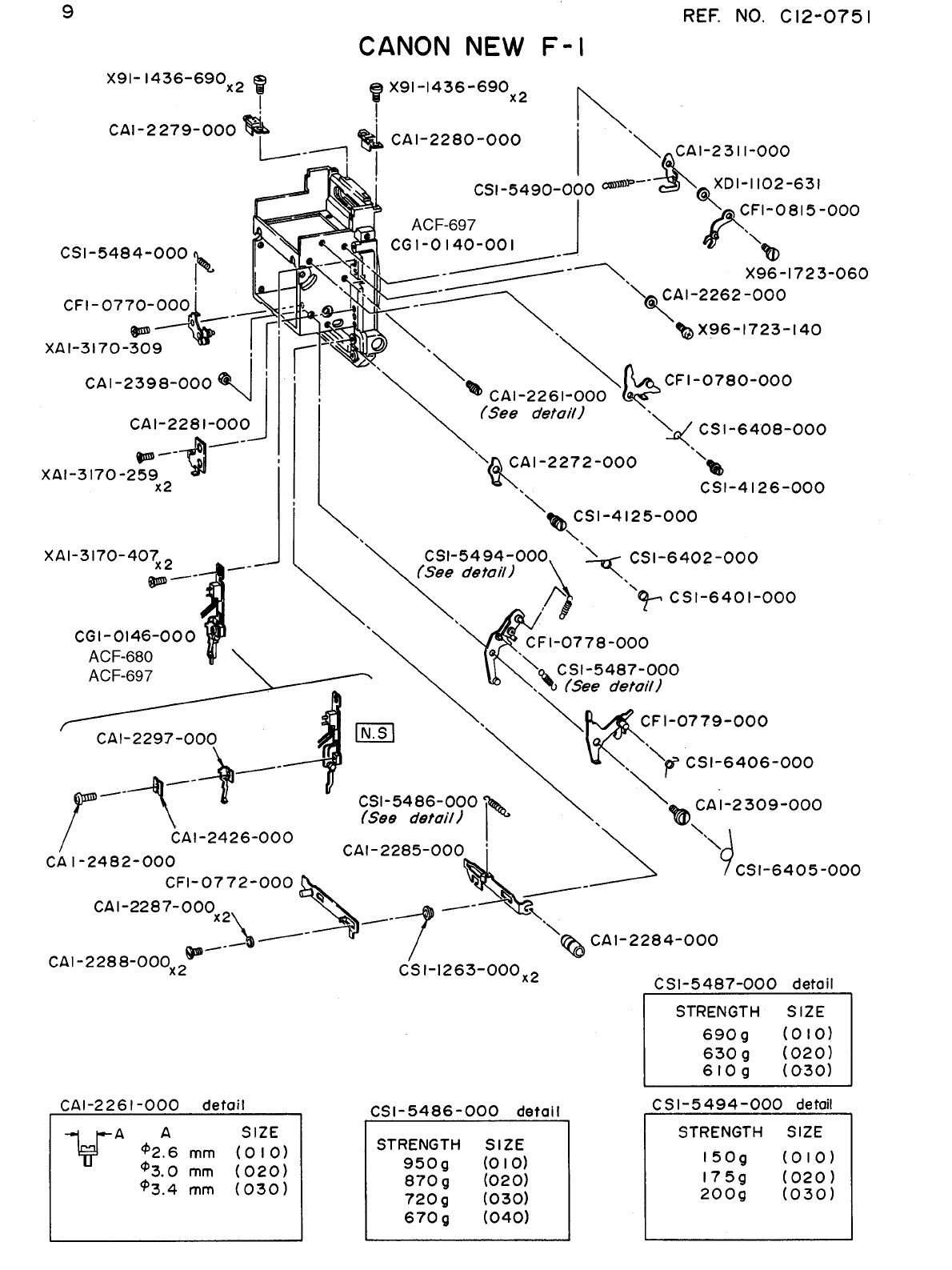

REF.NO.C12-0751
P A R T S L I S T
Pg.9
NEW PARTS NO. CLASS QTY DESCRIPTION
CA1-2261-000(XXX) D 1 STOPPER
CA1-2262-000 E 1 COLLAR
CA1-2272-000 E 1 LEVER, MIRROR RETURN
CA1-2279-000 D 1 CONTACT, FINDER(RIGHT)
CA1-2280-000 D 1 CONTACT, FINDER(LEFT)
CA1-2281-000 E 1 HOLDER, SPRING
CA1-2284-000 C 1 BUTTON, STOP DOWN MEASURING
CA1-2285-000 E 1 SLIDE, DIAPHRAGM CLOSING
CA1-2287-000 D 2 COLLAR
CA1-2288-000 E 2 SCREW
CA1-2297-000 C 1 CONTACT
CA1-2309-000 E 1 SCREW, SHAFT
CA1-2311-000 E 1 LATCH, MIRROR START
CA1-2398-000 E 1 NUT
CA1-2426-000 D 1 INSULATOR
CA1-2482-000 E 1 SCREW
CF1-0770-000 E 1 BASE, STOP DOWN LOCK
CF1-0772-000 E 1 SLIDE, A MODE(FOLLOW NEEDLE)
CF1-0778-000 E 1 LEVER, MIRROR CHARGE
CF1-0779-000 E 1 LEVER, MIRROR DRIVE
CF1-0780-000 E 1 LEVER, 1ST CURTAIN START
CF1-0815-000 E 1 LEVER, 1ST CURTAIN RELEASE
CG1-0140-001 E 1 PANEL, FRONT
CG1-0146-000 D 1 MODE ASS'Y, A
CS1-1263-000 E 2 COLLAR
CS1-4125-000 E 1 SCREW
CS1-4126-000 E 1 SCREW
CS1-5484-000 D 1 SPRING, COIL
CS1-5486-000(XXX) E 1 SPRING, COIL
CS1-5487-000(XXX) D 1 SPRING, COIL
CS1-5490-000 D 1 SPRING, COIL
CS1-5494-000(XXX) D 1 SPRING, COIL
CS1-6401-000 D 1 SPRING
CS1-6402-000 D 1 SPRING
CS1-6405-000 D 1 SPRING
CS1-6408-000 D 1 SPRING
X91-1436-690 4 SCREW
X96-1723-060 1 SCREW
X96-1723-140 1 SCREW
XA1-3170-259 2 SCREW
XA1-3170-309 1 SCREW
XA1-3170-407 2 SCREW
XD1-1102-631 1 WASHER


REF.NO.C12-0751
P A R T S L I S T
Pg.10
NEW PARTS NO. CLASS QTY DESCRIPTION
CA1-2011-000 D 1 GEAR, COUNTER
CA1-2012-000(XXX) C 1 RING, C
CA1-2017-000 C 1 RING, C
CA1-2020-000 D 1 SHAFT, SPROCKET
CA1-2021-000 E 1 STUD
CA1-2022-030(XXX) D 1 SCREW, SPROCKET
CA1-2024-000 E 1 CASE, CLICK
CA1-2033-000 D 1 CAM, RELEASE
CA1-2036-000 E 1 BASE, CONTACT
CA1-2037-000 D 1 INSULATOR
CA1-2038-000 C 1 CONTACT, RELEASE
CA1-2039-000(XXX) D 1 CONTACT, RELEASE-2
CA1-2040-000 D 1 CONTACT, RELEASE-3
CA1-2083-000 C 1 DIAL, FILM COUNTER
CA1-2439-000(XXX) D 1 WASHER
CA1-2444-000 C 1 LEATHER
CA1-2478-000 D 2 SHIELD, LIGHT
CA1-2480-000 D 1 INSULATOR
CF1-0706-000(XXX) D 1 LEVER, 2ND CURTAIN RELEASE
CF1-0709-000 E 1 LEVER, 2ND CURTAIN RELEASE
CF1-0804-000 C 1 PCB ASS'Y
CF1-0811-000 D 1 PLATE, CLICK
CF1-0812-000 D 1 PLATE, CLICK
CG1-0142-000 D 1 WINDING UNIT
CS1-5472-000 E 1 SPRING, COIL
CS1-6372-000 D 1 SPRING
CS1-6373-000 E 1 SPRING
CS1-6374-000 D 1 SPRING
CS1-6375-000 D 1 SPRING
CS1-6376-000 D 1 SPRING
CS1-6377-000 E 1 SPRING
CS1-7292-000 E 1 SPRING, PLATE
CY4-0056-000 D 1 SCREW
CY4-0057-000 D 1 SCREW
X91-1425-540 4 SCREW
X91-1435-900 2 SCREW
X91-1436-440 2 SCREW
X91-1725-260 2 SCREW
X96-2021-870 1 SCREW
XA1-1200-407 1 SCREW
XA1-3170-407 1 SCREW
XA1-7140-149 3 SCREW
XA1-7140-257 1 SCREW
XD1-1101-523 1 WASHER


REF.NO.C12-0751
P A R T S L I S T
Pg.11
NEW PARTS NO. CLASS QTY DESCRIPTION
CA1-1918-000(220) E 1 NUT, ADJUSTING
CA1-1918-000(225) E 1 NUT, ADJUSTING
CA1-2026-000 E 1 LEVER, DIAPHRAGM RELEASE
CA1-2028-000(XXX) E 1 SCREW
CA1-2201-000 C 1 CONTACT, BATTERY(-)
CA1-2202-000 E 1 SCREW
CA1-2203-000 D 1 CONTACT, EARTH
CA1-2210-000 E 1 COLLAR, STOPPER
CF1-0749-000 D 1 ARMATURE
CF1-0750-000 E 1 LEVER, ARMATURE RELEASE
CF1-0751-000 E 1 LEVER, MAGNET RELEASE
CF1-0753-000 E 1 BASE, CONTACT(-)
CG1-0134-000 D 1 MAGNET-2 UNIT
CG1-0135-000 D 1 CHAMBER UNIT, BATTERY
CG1-0256-000 E 1 SW5 ASS'Y
CS1-5480-000 C 1 CONTACT, SPRING
CS1-5481-000 C 1 CONTACT, SPRING
CS1-6390-000 D 1 SPRING
CS1-6391-000 D 1 SPRING
CS1-6392-000 D 1 SPRING
CS1-6393-000 D 1 SPRING
CS1-8304-000 C 1 SEAL, BATTERY
X96-1723-030 1 SCREW
X98-0104-830 1 WASHER
X99-0559-000 2 SCREW, SET
XA1-1170-229 1 SCREW
XA1-3140-257 2 SCREW
XA1-3140-289 2 SCREW
XA11170-169 2 SCREW
XA3-3170-409 1 SCREW
XA3-6170-409 1 SCREW
XD2-1100-102 2 SCREW


REF.NO.C12-0751
P A R T S L I S T
Pg.12
NEW PARTS NO. CLASS QTY DESCRIPTION
13-9523-000 E 1 NUT
13-9561-000 E 1 NUT
CA1-1918-000 D 1 NUT
CA1-1931-000 E 1 NUT, BRAKE
CA1-1943-000 E 1 COLLAR
CA1-1944-000 D 3 SCREW
CA1-1972-000 E 1 COLLAR
CA1-1979-000 E 2 WASHER
CA1-1980-000 C 2 LEATHER, 2ND CURTAIN BRAKE
CA1-1981-000 D 1 DISK, 2ND CURTAIN BRAKE
CA1-1985-000 E 1 LEVER, SIGNAL
CA1-1989-000 E 1 CAM, 2ND CURTAIN LATCH
CA1-2007-000 D 1 CLAW, COUNTER FEEDING
CA1-2035-000 D 1 SHAFT, SHUTTER RELEASE
CA1-2476-000 E 1 WASHER
CB1-1590-000 1 WASHER
CF1-0682-000 E 1 LEVER, MIRROR CHARGE
CF1-0683-000 E 1 LEVER, SIGNAL
CF1-0686-000 E 1 LEVER, SWITCH
CF1-0688-000 E 1 BASE, BRAKE
CF1-0689-000 D 1 BRAKE, 2ND CURTAIN
CF1-0690-000 C 1 CURTAIN, 1ST
CF1-0691-000 C 1 CURTAIN, 2ND
CF1-0742-000 E 1 LEVER, 1ST CURTAIN RELEASE
CF1-0789-000 D 1 SHIELD, LIGHT
CG1-0131-000 D 1 GEAR UNIT, MASTER
CG1-0132-000 D 1 DRUM UNIT, SPRING
CG1-0464-000(XXX) D 1 GEAR, AE COUPLER
CS1-0465-000 E 1 IDLER
CS1-1228-000 E 1 BUSH
CS1-1229-000 E 1 BUSH
CS1-1230-000 E 1 BUSH
CS1-4110-000 E 1 SCREW
CS1-4112-000 E 1 STUD
CS1-4113-000 E 1 STUD
CS1-4114-000 E 1 SCREW
CS1-4115-000 E 1 STUD
CS1-4119-000 E 1 SPRING
CS1-5466-000(XXX) E 1 SPRING, COIL
CS1-5468-000 D 1 SPRING, COIL
CS1-6355-000 E 1 SPRING
CS1-6355-020 E 1 SPRING
CS1-6359-000 D 1 SPRING
CS1-6360-000 E 1 SPRING
CS1-6361-000 E 1 SPRING
CS1-6368-000 E 1 SPRING
CS1-6369-000 E 1 SPRING
CS1-6370-000 E 1 SPRING
CS1-6371-000 E 1 SPRING
CS1-6387-000 E 1 SPRING
X31-6222-590 E 2 SCREW
X91-1737-210 E 1 SCREW
X91-1737-340 E 1 SCREW
X98-0303-930 E 1 WASHER
X98-0304-060 E 1 WASHER
XA1-1170-189 E 2 SCREW
XA1-1170-229 E 2 SCREW
XA1-1170-359 E 1 SCREW
XA1-3170-259 E 1 SCREW
XD1-1102-630 E 1 WASHER
XD1-1102-631 E 1 WASHER
XD2-1100-102 E 2 RING, E


REF.NO.C12-0751
P A R T S L I S T
Pg.13
NEW PARTS NO. CLASS QTY DESCRIPTION
13-9889-000 E 3 ROLLER
13-9991-000 D 1 CAM, CLUTCH
14-4498-000 C 51 BALL, STEEL
CA1-1949-000 D 1 SPOOL
CA1-1950-000 D 1 RATCHET, MULTI-EXPOSURE
CA1-1959-000 E 1 BASE, CONTACT
CA1-1960-000 D 1 CONTACT
CA1-1961-000 E 1 INSULATOR
CA1-1963-000 E 1 PLATE, CLUTCH HOLD
CA1-1964-000 E 1 SPACER, WINDING CAM
CA1-1965-000 D 1 CAM, WIINDING
CA1-1966-000 D 1 COUPLER, WINDING
CA1-1967-000(XXX) D 2 WASHER
CA1-1969-000 E 1 SPACER
CA1-1970-000 E 1 CAM, LOWER REVERSE LOCK
CA1-1971-000 E 1 CAM, UPPER REVERSE LOCK
CA1-2044-000 E 1 SPACER
CA1-2045-000 E 1 LEVER, M.E. LATCHET
CA1-2475-000 D 1 SHIELD, LIGHT
CF1-0687-000 D 1 SHAFT/GEAR, WINDING
CS1-0460-000 E 1 GEAR, SPOOL
CS1-0462-000 D 1 GEAR, WINDING COUPLER
CS1-1232-000 E 1 BUSHING
CS1-1233-000 E 1 HOLDER, WINDING GEAR
CS1-4111-000 E 1 STUD
CS1-4116-000 E 1 SCREW
CS1-4128-000 E 1 STUD
CS1-5496-000 B 3 COIL, SPRING
CS1-6357-000 E 1 SPRING
CS1-6358-000 E 1 SPRING
CS1-6378-000 E 1 SPRING
CY1-1210-000 C 1 SPOOL, ASS'Y
X91-1436-330 1 SCREW
X91-2035-910 1 SCREW
X96-1723-020 2 SCREW
X98-0403-970 1 WASHER
XA1-1170-287 2 SCREW
XA1-3170-229 3 SCREW
XD1-1102-112 1 WASHER
XD1-1104-131 1 WASHER
XD1-1104-133 1 WASHER


REF.NO.C12-0751
P A R T S L I S T
Pg.14
NEW PARTS NO. CLASS QTY DESCRIPTION
97-5733-000(XXX) E 1 SPRING, COIL
CA1-1991-000 E 1 CUSHION
CA1-1992-000 E 1 HOLDER, CUSHION
CA1-1999-000 E 1 LEVER, MAGNET CHARGE
CA1-2000-000 E 1 SCREW
CA1-2185-000 C 1 ARMATURE
CA1-2186-000 C 1 E RING
CA1-2484-000 E 1 COVER, DUST
CF1-0692-000 E 1 LEVER, MIRROR RELEASE
CF1-0693-000 E 1 LEVER, DIAPHRAGM RELEASE
CF1-0694-000 E 1 LEVER, MIRROR CHARGE
CF1-0695-000 E 1 LEVER, CHARGE
CF1-0696-000 E 1 LEVER, DIAPHRAGM RELEASE
CF1-0697-000 D 1 LEVER, DIAPHRAGM CHARGE
CF1-0698-000 D 1 LEVER, WINDING STOPPER
CF1-0699-000 D 1 LEVER, STOPPER CHARGE
CF1-0700-000 E 1 LEVER, CHARGE
CF1-0747-000 E 1 LEVER, ARMATURE
CG1-0133-000 D 1 MAGNET-3 UNIT
CS1-4120-000 E 1 SCREW
CS1-4121-000 E 1 SCREW, SHAFT
CS1-5469-000 D 1 SPRING, COIL
CS1-5470-000 E 1 SPRING, COIL
CS1-6362-000 E 1 SPRING
CS1-6363-000 E 1 SPRING
CS1-6364-000 E 1 SPRING
CS1-6365-000 E 1 SPRING
CS1-6366-000 E 1 SPRING
CS1-6367-000 E 1 SPRING
CS1-6388-000 D 1 SPRING
CS1-6389-000 D 1 SPRING
X91-1736-320 1 SCREW
X91-1737-350 1 SCREW
X98-0104-910 1 WASHER
X98-0205-030 1 WASHER
X98-0304-450 1 WASHER
XA1-1170-409 1 SCREW
XA1-3170-189 1 SCREW
XA1-3170-359 2 SCREW
XA1-7170-189 1 SCREW
XD1-1101-531 1 WASHER
XD1-1101-820 1 WASHER
XD1-1102-320 1 WASHER
XD2-1100-102 1 RING, E
XD2-1100-131 1 RING, E


REF.NO.C12-0751
P A R T S L I S T
Pg.15
NEW PARTS NO. CLASS QTY DESCRIPTION
13-9872-000 B 2 RING, NECK STRAP
14-4498-000 C 39 BALL, STEEL
CA1-1919-000 E 1 SHAFT, IDLER
CA1-1920-000 E 1 SHAFT, BRAKE
CA1-1924-000 D 3 SCREW
CA1-1928-000 E 2 WASHER
CA1-1929-000 C 2 LEATHER, 1ST CURTAIN BRAKE
CA1-1930-000 D 1 DISK, 1ST CURTAIN BRAKE
CA1-1931-000 E 1 NUT, BRAKE
CA1-1951-000 E 1 BASE, CONTACT
CA1-1952-000 D 1 CONTACT, X
CA1-1953-000 D 2 INSULATOR
CA1-1954-000 D 1 CONTACT
CA1-1955-000 D 1 CONTACT
CA1-1958-000(XXX) D 1 STOPPER, X CONTACT
CA1-2390-000(XXX) DD 1 WASHER
CA1-2396-000(XXX) D 1 WASHER
CA1-2483-000 D 1 INSULATOR
CF1-0678-000 E 1 BRAKE, 1ST CURTAIN
CF1-0679-000 E 1 LEVER, 1ST CURTAIN BRAKE SET
CS1-0458-000 D 1 GEAR, SPROCKET
CS1-0459-000 E 1 IDLER
CS1-4108-000 E 1 SCREW
CS1-5466-000(XXX) D 1 SPRING, COIL
CS1-6352-000 E 1 SPRING
CY1-1179-000 C 2 LUG, NECK STRAP
X91-1714-340 3 SCREW
X91-1736-950 2 SCREW
X91-1737-370 1 SCREW
X98-0403-960 1 WASHER
XA1-1170-709 2 SCREW


REF.NO.C12-0751
P A R T S L I S T
Pg.16
NEW PARTS NO. CLASS QTY DESCRIPTION
13-8505-000 A 2 SHIELD, LIGHT
13-9880-000 E 2 PIN, STOPPER
14-4498-000 C 24 BALL, STEEL
CA1-1912-000 D 1 CUSHION
CA1-1913-000 D 1 HOLDER, SHAFT
CA1-1914-000 D 1 SHIELD, LIGHT
CA1-1915-000 E 1 STUD
CA1-1916-000 E 1 SHAFT, RELEASE SPRING
CA1-1917-000 E 1 SHAFT, GEAR
CA1-1921-000 D 1 SPROCKET
CA1-1922-000 E 1 CLUTCH, SPROCKET
CA1-1935-000 E 1 NUT
CA1-1947-000 E 1 LEVER, SWITCH(E)
CA1-2133-000 C 1 STABILIZER, CARTRIDGE
CA1-2386-000 D 1 GUIDE, FILM
CA1-2391-000(XXX) D 1 WASHER
CF1-0677-000 D 1 GEAR, SPROCKET
CF1-0680-000 E 1 RELEASE, MECHANICAL
CF1-0681-000 D 1 SLIDE, MECHANICAL RELEASE
CF1-0684-000 E 1 LEVER, ACTIVATOR
CF1-0711-000 D 1 CONTACT, DATA BACK
CS1-0456-000 D 1 GEAR
CS1-1231-000 E 1 STUD,WINDING GEAR
CS1-4106-000 E 1 STUD
CS1-4107-000 E 1 STUD
CS1-4109-000 E 1 STUD
CS1-5467-000 D 1 SPRING, COIL
CS1-6351-000 E 1 SPRING
CS1-6354-000 E 1 SPRING
CS1-6356-000 E 1 SPRING
CY1-1079-000 E 1 BODY
X91-1436-730 2 SCREW
X91-1726-330 2 SCREW
X91-1737-360 1 SCREW
X96-1723-230 2 SCREW
X98-0205-020 1 WASHER
XA1-3170-229 3 SCREW
XA1-3170-259 3 SCREW
XA1-3170-359 3 SCREW
XD1-1101-831 1 WASHER

REF.NO.C12-0751
E L E C T R I C P A R T S L I S T
Pg.17
NEW
SYMBOL PARTS NO. CLASS QTY DESCRIPTION REMARK
CY4-0055-000 D1RESISTOR, HIGH VOLTAGE 50 OHM 1/8W ACF-545
IC1 CH4-0055-000 C1IC T2682A
R1 VR9-1103-000 E1RESISTOR 33KOHM 1/8W
R1 VR9-1109-000 E1RESISTOR 56KOHM 1/8W
R1 VR9-1367-000 E1RESISTOR 24.9KOHM 1/8W
R1 VR9-1412-000 E1RESISTOR 91KOHM 1/8W
R1 VR9-1753-000 E1RESISTOR 47KOHM 1/8W
R1 VR9-1888-000 E1RESISTOR 27KOHM 1/8W
R1 VR9-1889-000 E1RESISTOR 30KOHM 1/8W
R1 VR9-1891-000 E1RESISTOR 36KOHM 1/8W
R1 VR9-1892-000 E1RESISTOR 39KOHM 1/8W
R1 VR9-1893-000 E1RESISTOR 43KOHM 1/8W
R1 VR9-1897-000 E1RESISTOR 68KOHM 1/8W
R1 VR9-1899-000 E1RESISTOR 82KOHM 1/8W
R1 VR9-1970-000 E1RESISTOR 300KOHM 1/8W
R1 VR9-2098-000 E1RESISTOR 130KOHM 1/8W
R1 VR9-2099-000 E1RESISTOR 180KOHM 1/8W
R1 VR9-3055-000 E1RESISTOR 23.7 KOHM 1/8W
R2 VR9-1103-000 E1RESISTOR 33KOHM 1/8W
R2 VR9-1109-000 E1RESISTOR 56KOHM 1/8W
R2 VR9-1367-000 E1RESISTOR 24.9KOHM 1/8W
R2 VR9-1412-000 E1RESISTOR 91KOHM 1/8W
R2 VR9-1753-000 E1RESISTOR 47KOHM 1/8W
R2 VR9-1888-000 E1RESISTOR 27KOHM 1/8W
R2 VR9-1889-000 E1RESISTOR 30KOHM 1/8W
R2 VR9-1891-000 E1RESISTOR 36KOHM 1/8W
R2 VR9-1892-000 E1RESISTOR 39KOHM 1/8W
R2 VR9-1893-000 E1RESISTOR 43KOHM 1/8W
R2 VR9-1897-000 E1RESISTOR 68KOHM 1/8W
R2 VR9-1899-000 E1RESISTOR 82KOHM 1/8W
R2 VR9-1970-000 E1RESISTOR 300KOHM 1/8W
R2 VR9-2098-000 E1RESISTOR 130KOHM 1/8W
R2 VR9-2099-000 E1RESISTOR 180KOHM 1/8W
R2 VR9-3055-000 E1RESISTOR 23.7KOHM 1/8W
R6 CH9-0059-000 E1RESISTOR 1.96KOHM
R6 CH9-0060-000 E1RESISTOR 2.0KOHM
R6 CH9-0061-000 E1RESISTOR 2.05KOHM
R1 VR9-1421-000 E1RESISTOR 301KOHM 1/8W
RMTV VR5-0131-400 E1RESISTOR 140 OHM 1/8W ACF-642
RMTV VR5-0131-690 E1RESISTOR 169 OHM 1/8W ACF-642

REF.NO.C12-0751
E L E C T R I C P A R T S L I S T
Pg.18
NEW
SYMBOL PARTS NO. CLASS QTY DESCRIPTION REMARK
RMTV VR5-0131-960 E1RESISTOR 196 OHM 1/8W ACF-642
RMTV VR5-0132-260 E1RESISTOR 226 OHM 1/8W ACF-642
RMTV VR5-0132-490 E1RESISTOR 249 OHM 1/8W ACF-642
RMTV VR5-0132-740 E1RESISTOR 274 OHM 1/8W ACF-642
RMTV VR5-0133-010 E1RESISTOR 301 OHM 1/8W ACF-642
RMTV VR5-0133-320 E1RESISTOR 332 OHM 1/8W ACF-642
RMTV VR5-0133-650 E1RESISTOR 365 OHM 1/8W ACF-642
RMTV VR5-0133-830 E1RESISTOR 383 OHM 1/8W ACF-642
RMTV VR5-0140-101 E1RESISTOR 100 OHM 1/8W ACF-642
RMTV VR5-0140-121 E1RESISTOR 120 OHM 1/8W ACF-642
RMTV VR5-0140-180 E1RESISTOR 18OHM 1/8W ACF-642
RMTV VR5-0140-470 E1RESISTOR 47OHM 1/8W ACF-642
RMTV VR5-0140-750 E1RESISTOR 75OHM 1/8W ACF-642
RAE VR5-0131-822 E1RESISTOR 18.2 KOHM 1/8W ACF-642
RAE VR5-0132-002 E1RESISTOR 20.0 KOHM 1/8W ACF-642
RAE VR5-0132-212 E1RESISTOR 22.1 KOHM 1/8W ACF-642
RAE VR5-0132-432 E1RESISTOR 24.3 KOHM 1/8W ACF-642
RAE VR5-0132-742 E1RESISTOR 27.4 KOHM 1/8W ACF-642
RAE VR5-0133-012 E1RESISTOR 30.1 KOHM 1/8W ACF-642
RAE VR5-0133-322 E1RESISTOR 33.2 KOHM 1/8W ACF-642
RAE VR5-0133-652 E1RESISTOR 36.5 KOHM 1/8W ACF-642
RAE VR5-0133-922 E1RESISTOR 39.2 KOHM 1/8W ACF-642
RAE VR5-0134-322 E1RESISTOR 43.2 KOHM 1/8W ACF-642
RAE VR5-0134-752 E1RESISTOR 47.5 KOHM 1/8W ACF-642
RAE VR5-0135-112 E1RESISTOR 51.1 KOHM 1/8W ACF-642
VR5-0140-103 E1RESISTOR
10 KHOM 1/8W
AG1-036
R42 VR9-1103-000 E1RESISTOR 33 KHOM 1/8W
R42 VR9-1109-000 E1RESISTOR 56 KHOM 1/8W
R42 VR9-1306-000 E1RESISTOR 86.6 KHOM 1/8W
R42 VR9-1308-000 E1RESISTOR 95.3 KHOM 1/8W
R42 VR9-1309-000 E1RESISTOR 100 KHOM 1/8W
R42 VR9-1310-000 E1RESISTOR 105 KHOM 1/8W
R42 VR9-1311-000 E1RESISTOR 110 KHOM 1/8W
R42 VR9-1312-000 E1RESISTOR 115 KHOM 1/8W
R42 VR9-1313-000 E1RESISTOR 121 KHOM 1/8W
R42 VR9-1314-000 E1RESISTOR 127 KHOM 1/8W
R42 VR9-1315-000 E1RESISTOR 133 KHOM 1/8W
R42 VR9-1316-000 E1RESISTOR 140KHOM 1/8W
R42 VR9-1317-000 E1RESISTOR 147KHOM 1/8W
R42 VR9-1318-000 E1RESISTOR 154 KHOM 1/8W

REF.NO.C12-0751
E L E C T R I C P A R T S L I S T
Pg.19
NEW
SYMBOL PARTS NO. CLASS QTY DESCRIPTION REMARK
R42 VR9-1597-000 E1RESISTOR 51 KHOM 1/8W
R42 VR9-1753-000 E1RESISTOR 47 KHOM 1/8W
R42 VR9-1885-000 E1RESISTOR 16 KHOM 1/8W
R42 VR9-1887-000 E1RESISTOR 24 KHOM 1/8W
R42 VR9-1892-000 E1RESISTOR 39 KHOM 1/8W
R42 VR9-1896-000 E1RESISTOR 62 KHOM 1/8W
R42 VR9-1897-000 E1RESISTOR 68 KHOM 1/8W
R42 VR9-1898-000 E1RESISTOR 75 KHOM 1/8W
R42 VR9-1899-000 E1RESISTOR 82 KHOM 1/8W
RTSC VR5-0133-922 E1RESISTOR 39 KHOM 1/8W
VR5-0134-322 E1RESISTOR 43 KHOM 1/8W
VR5-0134-752 E1RESISTOR 47 KHOM 1/8W
VR5-0135-112 E1RESISTOR 51 KHOM 1/8W
VR5-0135-622 E1RESISTOR 56 KHOM 1/8W
Tr2 WA2-0229-000 D1TRANSISTOR 2SD813
VR2 VR9-1660-000 E1RESISTOR, VARIABLE 330OHM
Y11-3701-000 LEAD WHITE
Y11-3702-000 LEAD BLACK
Y11-3707-000 LEAD YELLOW
Y11-3901-000 LEAD WHITE
Y11-3903-000 LEAD RED
Y11-3906-000 LEAD ORANGE
Y11-3909-000 LEAD GREEN
Y11-4501-000 LEAD WHITE
Y11-4502-000 LEAD BLACK
Y11-4503-000 LEAD RED
Y11-4506-000 LEAD ORANGE
Y11-4507-000 LEAD YELLOW
Y11-4509-000 LEAD GREEN
Y11-4511-000 LEAD BLUE
Y11-4512-000 LEAD PURPLE
Y11-4514-000 LEAD GRAY
Y11-7312-000 HEAT SHRINKABLE TUBE
