Canon Powershot S230 Users Manual
S230 to the manual 4a35ba73-0def-4247-9c91-f3d88bf1ed99
2015-01-23
: Canon Canon-Powershot-S230-Users-Manual-241705 canon-powershot-s230-users-manual-241705 canon pdf
Open the PDF directly: View PDF ![]() .
.
Page Count: 137 [warning: Documents this large are best viewed by clicking the View PDF Link!]


SAFETY PRECAUTIONS
The following precautions should be observed when servicing.
1. Since many parts in the unit have special safety-related characteristics, always use genuine CANON replacement parts.
Especially critical parts in the power circuit block should not be replaced with other makes.
Critical parts are marked with ! in the schematic diagrams.
2. When servicing, observe the original lead dress. If a short circuit is found, replace all parts which have been overheated or damaged
by the short circuit.
3. After servicing, see to it that all the protective devices such as insulation barriers, insulation papers shields are properly installed.
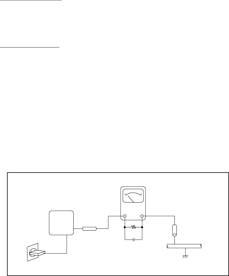
4. After servicing, make the following leakage current checks to prevent the customer from being exposed to shock hazards.
4-1 Leakage Current Cold Check
1) Unplug the AC cord and connect a jumper between the two prongs on the plug.
2) Measure the resistance value, with an ohmmeter, between the jumpered AC plug and each exposed metallic cabinet part
on the equipment such as screwheads, connectors, control shafts, etc. When the exposed metallic part has a return path to
the chassis, the reading should be between 1MΩ and 5.2MΩ. When the exposed metal does not have a return path to the
chassis, the reading must be ∞.
4-2 Leakage Current Hot Check
1) Plug the AC cord directly into the AC outlet. Do not use an isolation transformer for this check.
2) Connect a 1.5KΩ 10 watt resistor, paralleled by 0.15µF capacitor, between each exposed metallic parts on the unit and a
good earth ground such as a water pipe, as shown in the figure below.
3) Use an AC voltmeter, with 1000Ω/volt or more sensitivity, to measure the potential across the resistor.
4) Check all exposed metallic parts of the cover (Cable connection, Handle bracket, metallic cabinet.
Screwheads, Metallic overlays, etc), and measure the voltage at each point.
5) Reverse the AC plug in the AC outlet and repeat each of the above measurements.
6) The potential at any point should not exceed 0.75V RMS.
A leakage current tester (FLUKE MODEL : 8000A equivalent) may be used to make the hot checks.
Leakage current must not exceed 0.5 milliamp.
In case a measurement is outside of the limits specified, there is a possibility of a shock hazard, and corrective action must
be taken before returning the instrument to the customer.
Water pipe
(Earth Ground)
1.5KΩ
0.15µF
Test all
exposed
metal parts
Figure. 1 Leakage Current Hot Check
AC OUTLET
AC VOLTMETER
DEVICE
UNDER
TEST
Application
This manual has been issued by Canon Inc. for qualified persons to learn technical theory, and
repair of the products.
Corrections
This manual could include typographical errors or technical inaccuracies due to improvements or
changes in the products. When changes occur in applicable products or in the content of this manual,
Canon will release service manual report as the need arises. In the event of major changes in the
contents of this manual over a long or short period, Canon may issue new editions of this manual.
The following paragraph does not apply to any countries where such provisions are inconsistent
with local law.
Trademarks
The product names and company names described in this manual are the registered trademarks of
the individual companies.
Copyright
This manual is copyrighted with all rights reserved. Under the copyright laws, this manual may not
be copied, reproduced, published (including on the World Wide Web) or translated into another
language, in whole or in part, without the written consent of Canon Inc..
Copyright © 2002 by Canon Inc.
CANON INC.
Digital Imaging Products Service Dept.
30-2, Shimomaruko 3-Chome, Ohta-ku,
Tokyo 146-8501, Japan

1 Development Background
1-1 Development Objectives --------------------------------------------------------------------------------------------------- 1-1
1-2 Product Concept ------------------------------------------------------------------------------------------------------------- 1-1
1-3 Design Concepts------------------------------------------------------------------------------------------------------------- 1-4
1-4 Spec. comparison between IXY DIGITAL 320 and 200a ------------------------------------------------------------- 1-5
2 Features
2-1 High Grade Design / Ultra Compact-------------------------------------------------------------------------------------- 1-6
2-2 Full Features / Operation Ease -------------------------------------------------------------------------------------------- 1-7
2-3 High Image Quality --------------------------------------------------------------------------------------------------------1-10
2-4 System Accessory / Application Softwares-----------------------------------------------------------------------------1-11
3 Exterior
3-1 Exterior Photos ------------------------------------------------------------------------------------------------------------ 1-16
3-2 6-dimensional diagram --------------------------------------------------------------------------------------------------- 1-17
3-3 Nomenclature ---------------------------------------------------------------------------------------------------------------1-18
3-4 UI Information --------------------------------------------------------------------------------------------------------------1-19
4 Specifications
4-1 Camera Specifications -----------------------------------------------------------------------------------------------------1-21
4-2 System Requirements ------------------------------------------------------------------------------------------------------1-32
5 System
5-1 Accessories Compatibility ----------------------------------------------------------------------------------------------- 1-33
5-2 System diagram------------------------------------------------------------------------------------------------------------ 1-35
6 Additional
6-1 iSAP (Intelligent Scene Andlysis based on photographic Space) Technology ------------------------------------1-36
CHAPTER 1. GENERAL DESCRIPTION
OF PRODUCT
CONTENTS
*The “IXY DIGITAL 320” Product designation used in this document refers to the IXY DIGITAL 320,
The DIGITAL IXUS v3 and PowerShot S230 DIGITAL ELPH designations are used in various marketing areas.

1-1
1 Development Background
1–1 Development Objectives
The original IXY DIGITAL first put on sale in May 2000 has evolved through the IXY DIGITAL 200, released
in 2001, leading up to the present IXY DIGITAL 200a in 2002. Nevertheless, in the last year, our competitors
have been releasing cameras with similar (flat-front, compact, high-grade) concepts to the IXY DIGITAL
series, and 3-megapixel CCD models have also been appearing.
While the IXY DIGITAL series has been maintaining its popularity since it went on sale by incorporating
consistently superior “picture quality”, “functions” and “operability” to that of competitive models through
model changes, fans of the IXY have been clamoring for 3-megapixel CCD capability.
With this background in mind, the IXY DIGITAL 320, equipped with a 3-megapixel CCD and the newly
developed digital imaging processor “DIGIC (Digital Imaging Processor)”, will be added to the series. By also
further enhancing the movie features, we have produced a camera that will maintain our advantage over rival
models.
1–2 Product Concepts
The IXY DIGITAL 320 will have the same basic exterior appearance as the IXY DIGITAL 200a, with its
highly perfected finish; however, to differentiate it from the IXY DIGITAL 200a, the processing of external
parts and materials has been revised in order to generate more appeal for its higher picture quality as a result of
the 3-megapixel CCD and its improved movie functions.
Furthermore, “Direct Print” support, a basic concept of Canon’s digital cameras, provides an environment in
which high-picture-quality prints can be obtained easily by combining the camera with a CP-100/10 card photo
printer or an Exif 2.2 compatible Bubble Jet printer (BJ 895PD/BJ 535PD).
+
IXY DIGITAL 200a
“May, 2002”
IXY DIGITAL 320
“ October, 2002”
Î
Higher Image Quality
3M-pixel CCD
DIGIC
(Digital Imaging Processor)
High quality VGA size movie
Higher Features
Continuous movie recording
9-point AiAF
Stylish
&
Convenient

1-2
High grade design / Ultra compact
N: New features unique to the IXY DIGITAL 320 (autumn 2002 model)
U: Updated features from the IXY DIGITAL 200a (already equipped on other models)
U - Thin stylish design for enhanced high-grade character
- Low-temperature, polysilicon 1.5-inch LCD monitor with power-saving design
- Small, high-efficiency light guide flash enhances reliability
- CSP-IC on both side of the board allows higher density mounting
N - Selectable nine-points AiAF and single-point AF (range frame can be set arbitrarily)
N - Settable display times for rec review (Off, 2 to 10 seconds)
N - Continuous movie recording and replay with audio with long filming times (VGA : 30 sec. /QVGA : 3
minutes / QQVGA : 3 minutes)
N - Unwanted scenes can be deleted in movie playback mode
N - New fast image storage CF card (256 MB)
N - Driver-less computer connections with Picture Transfer Protocol (PTP) support
U - Digital zoom function with continuously changing angle of view (Approx. 6.4x when used in combination
with an optical zoom)
U - Total of 12 image quality modes (4 recording pixels x 3 compression ratio)
U - Direct Print function with cropping capability for dedicated printers (card photo
printers CP-100/10) and Bubble Jet printers (BJ 895PD/535PD/F890PD)
-Photo effect modes (Vivid color, Neutral color, Low sharpening, Sepia and Black & White) are provided
- Real-image optical zoom viewfinder
- Two types of metering function that are spot metering and evaluative metering
- AF, AE and FE lock feature enabling focus and exposure lock when taking photos
- On/Off selection of AF-assist Beam available
- Fifteen-second long exposure added to 1 to 1/1500-second shutter speeds
- Continuous shooting (approx. 2 images/sec. when LCD monitor is off)
- Stress free operation owing to DIGIC (Digital Imaging Processor) and large capacity buffer memory
- SI (Super Intelligent) sensor automatically detects vertical or horizontal photography
- Convenient operation using cross-configured buttons
- Built-in flash with five flashing modes
- Built-in flash range of 3.0 m (wide-angle end) and slow-sync speed mode is provided
- Self-Timer function (selectable of 2 or 10 seconds)
- Histogram displays during rec review function and playback
- Reset of all settings by one-touch operation
- Mode switch to select still photography, movie photography or playback
- High-speed image feed on playback
- Magnified playback for convenient image confirmation (from approx. 2x to 10x zoom)
- Supports DPOF slideshows and image transfers
Full Features / Operation Ease

1-3
- Selectable video output format (NTSC/PAL)
- High-speed image transfer on USB Interface
- International supporting twelve languages
System accessories / Application software
High Image Quality
N - 1/2.7-type approx. 3.2M camera effective pixels CCD (3.3M-pixels in total)
N - High definition and fast processing with the newly developed DIGIC (Digital Imaging Processor)
N - VGA size movie achieves higher image quality
- Fine color reproduction owing to primary color filters
- High-resolution retractable 2x zoom lens
- New image capturing optics brings out high resolution
- Noise reduction feature for high S/N
- Built-in SI Sensor enhances precision of AE, AF and AWB
- Wide range of ISO-equivalent speed settings (Auto/ISO 50/100/200/400 equivalent)
- High-precision white balance (Auto + Five preset positions + Custom)
- Totally round aperture for better background blur
- Applying to Exif 2.2
- Waterproof case good to 30 m (100 ft) underwater (Equipped with flash diffusion plate)
- Compact Li-ion battery with hight energy capacity (Nominal capacity : 840 mAH)
- Compact car battery charger for Li-ion battery
- Compact power adapter also compatible with the PS A-series
- Full featured application software
N - ZoomBrowser EX 4.0 (Win) made more ergonomic
(ImageBrowser 2.7 (for Mac) is as in the past)
- Photorecord 1.6 (Win) for easy layout and printing of many pictures
-PhotoStitch 3.1 for creating panoramic pictures with precision
-RemoteCapture 2.6 for remote picture-taking through a PC (permits display of the Finder
screen on the PC)
N - New File Viewer Utility 1.0 application for developing RAW images
- TWAIN Driver 5.0 / WIA Driver 5.0 (Win)
-USB Mounter 1.8 (Macintosh) that allows the system to handle the camera as a card reader
-Printer Driver CP-100/CP-10 2.1 for prints from a pictures in PC
-Adobe Acrobat Reader 4.0 for Printer driver’s manual
-Proven third-party software
ArcSoft PhotoImpression 4.0 (Win) / 4.0 (Mac ) (processing/editing for still images)
ArcSoft VideoImpression 1.7 (Win) / 1.6 (Mac) (processing/editing for movies)
1-4
1–3 Design Concepts
The IXY DIGITAL 320 strives for an evolution befitting a premium three-megapixel camera while
continuing the precedent set by the basic external appearance of the IXY DIGITAL 200a.
This model uses a different type of processing for external parts and materials in order to create more
appeal for the high picture quality sensor and lens, achieving a refined texture with more character that
instills a sense of satisfaction through the pleasure of possessing a tool.
zSilky hairline finishing given to the circle section
On our previous models, hairline processing was applied after blast processing of stainless materials to create
a circle motif on the body around the lens. However, for the IXY DIGITAL 320, the base stainless materials
have been replaced with a highly luminous type and the area around the lens is masked when blast
processing is applied. Following this, through hairline processing, a more subtle and higher quality hairline
finishing than previous models is achieved.
As a synergetic effect of preserving the luminance of the recessed megapixel and lens inscriptions in the
circle area, we have been able to make the letters stand out in bold relief.
zUse of a light gold emblem and revamped finishing of metal-plated parts
The three metallic parts on previous models — the zoom lever, strap clip and Canon emblem — expressed a
sense of class with a trivalent chrome plating with a black shine.
On the IXY DIGITAL 320, however, nickel-velour (satin finishing) plating with a bright impression is employed
for the zoom lever and strap clip parts, while the emblem section has been plated with a light gold giving off
a golden glimmer. Combining these elements convey an image of refined character like a personal accessory
rather than just the sensation of a camera.

1-5
1-4 Spec. Comparison between IXY Digital 320 and IXY Digital 200a
IXY DIGITAL 320 IXY DIGITAL 200a
Image sensor (CCD) Camera effective pixels : Approx. 3.2 M 1/2.7 inch size
(Total pixels: Approx. 3.3 M)
Camera effective pixels : Approx. 2 M 1/2.7 inch size (Total
pixels: Approx. 2.1 M)
Color filter Primary color filter (Beyer) ←
Lens (35mm film equivalent) 35-70 mm, F2.8-4.0 ←
Optical zoom 2x ←
Digital zoom Approx. 3.2x 2.5x
Normal 47cm - infinity 57cm - infinity
Macro 10 - 47cm(W), 27 - 47cm(T) 10 - 57cm(W), 27 - 57cm(T)
Optical viewfinder Real-image optical zoom view finder ←
LCD monitor 1.5 inch low -temperature poly cry stalline sillic on TFT c olor
LCD ←
Autofocus 9 points (AiAF) / 1 point (Center)
(AF lock is available)
3 points (AiAF) / 1 point (Center)
(AF lock is available)
Metering m odes Evaluation (AF point-linked) / Spot ←
Exposure control system Program AE ←
Exposure compensation +/- 2 stops in 1/3-stop increments ←
Sensitivity (ISO film speed) Auto / ISO 50/100/200/400 equivalent ←
White balance Auto + Pre-set (5 positions) + Manual ←
Shutter type Mechanical shutter + electronic shutter ←
Shutter speed 15 - 1/1500 sec. ←
Flash range 47 cm - 3.0 m (W), 47 cm - 2.0 m (T) 57 cm - 3.0 m (W), 57 cm - 2.0 m (T)
Shooting specifications Auto/ Manual/ Stitch assist/ Movie ←
Continuous shooting Approx. 2.0 images/sec (L/F, LCD Monitor OFF) Approx. 2.5 images/sec (L/F, LCD Monitor OFF)
Recording media CompactFlash card (Type I) ←
Still Design rule for Camera File system,
DPOF(Ver 1.1) compliant ←
Movi e AVI ←
Still JPEG (Exif 2.2 compliant) / RAW ←
Movi e Image: Motion JPEG Audio:WAVE(Monaural) ←
Still (L) 2048×1536, (M1) 1600×1200
(M2) 1024×768, (S) 640×480
(L) 1600×1200
(M) 1024×768, (S) 640×480
Movi e
(VGA) 640×480 Approx. 30 sec. at 15 fps
(QVGA) 320×240 Approx. 3 min. at 15 fps
(QQVGA) 160×120 Approx. 3 min. at 15 fps
(VGA) 640×480 Approx. 4 sec. at 20 fps
(QVGA) 320×240 Approx. 10 sec. at 20 fps
(QQVGA) 160×120 Approx. 30 sec at 20 fps
JPEG compression mode (SF/F/N) x (L/M1/M2/S) (12 pattern) (SF/F/N) x (L/M/S) (9 pattern)
Play mode Single / Index (9 thumbnail images) / Slide show / Movie /
Magnification (2-10x) ←
Direct print O←
Interface USB, Audio / Video output ←
Source
Rechargeable Lithium battery (NB-1LH)
/ Compact Pow er Adapter (CA-PS500) + DC coupler (DR-
500) / Car Battery Adapter (Optional Car Battery Cable
CBC-NB1 is recommended)
←
Perfor
mance
Shooting capacity:
Approx. 170 images (LCD monitor ON)
Approx. 420 images (LCD monitor OFF)
Playback time: Approx. 130 min.
Shooting capacity:
Approx. 150 images (LCD monitor ON)
Approx. 420 images (LCD monitor OFF)
Playback time: Approx. 100 min.
Dimensions (W x H x D) 87.0 x 57.0 x 26.7 mm ←
Approx. 180 g ←
W
e
i
g
ht
(
exc
l
u
di
ng
b
a
tt
er
i
es
and CF card
)
Recording pixels
Sh
oo
ti
ng
di
s
t
ance
(from tip of the
lensbarrel
)
Power supply
File format
Recording format
1-6
2 Features
2–1 High Grade Design / Ultra Compact
- Thin stylish design for enhanced high-grade character
The IXY DIGITAL 320 strives for an evolution befitting a premium three-megapixel camera while continuing
the precedent set by the basic external appearance of the IXY DIGITAL 200a.
This model uses a different type of processing for external parts and materials in order to create more appeal
for the high quality picture sensor and lens, achieving a refined texture with more elegant character that instills
a sense of satisfaction through the pleasure of possessing a tool.
(See Design Concepts on page 5)

1-7
Photo 2-1 9-point AiAF
2-2 Full Features / Operation Ease
- Selectable 9-point AiAF and single-point AF (range frame can be set arbitrarily)
The AiAF range frame for the IXY DIGITAL 320 has been increased from the previous 3 points (IXY DIGITAL
200a) to 9 points. As a result, framing unconstrained by the position of
the subject is possible. With multiple focus points, the respective
range
frames for the focus points are displayed in green (when there are
two or more focus points, the range frames for all focus points are
shown).
IXY DIGITAL 320 also employs standard AF system that use
AF frame with a single center point, so that user can choose the
convenient method depending on photographic conditions.
- Settable display times for rec review (2 to 10 seconds)
The Ixy digital 320 is specified so that the image-display time* in rec review (confirmation of recorded image)
can be set between two and 10 seconds in 1 second intervals. In this way, users can select a duration to suit
their applications.
* “Off” can also be set
- Continuous movie recording and playback with audio with long filming times (3 minutes)
(selectable from QVGA and QQVGA)
The Ixy digital 320 can record moving images at 15 frames per second along with audio in 2 formats, QVGA
(320 by 240 pixels) and QQVGA (160 x 120 pixels). Because a method is employed that consecutively writes
images that are temporary stored in the buffer to the CF card while recording, long continuous filming times are
also achieved.
In practice, if the write speed of the CF card is slower*1 than the speed to write an image to the buffer, the
recording will stop when the buffer capacity is reached. Taking this circumstance into account, the specification
limits the maximum recording time in both QVGA and QQVGA formats to three minutes. Even after three
minutes of elapsed filming, the G3 allows the next recording to be resumed in less time than previous models.
During filming, the values for the focus, exposure, white balance and zoom position determined at the beginning
are used continuously to the end of the recording. The storage time is also displayed on the LCD monitor during
filming.
The file is saved in AVI format, while the image is saved as Motion JPEG data and the audio data in WAVE
format (mono).
*1 The write speed varies depending on the brand and capacity of the CF card.
*2 If the free space on the CF card is less than the size of the recording, recording will stop just prior
to the CF card reaching full capacity.
Figure 2–1 Conceptual diagram of continuous moving image recording
Signal Processing/Resize/JPEG
Buffer
Memory
File
Format CF Card
CCD
Transfer the foramer image
while storage new image

1-8
50 100 150 200 250
1600X1200
800X 600
1280X960
1024X 768
640X480
û´äm ( û´ )
35mm Ö ¤ ì áãE mm
IXY DIGITAL 200/200a
2048X1536
IXY DIGITAL 320
<at L size>
Recording pixels (Image quality)
Focal length (35mm film equivalent (mm))
- Unwanted scenes can be deleted in movie playback mode
The Ixy digital 320 allows unwanted sections to be deleted in the movie playback mode. However, the sections
that can be deleted are either from the start of the recording to an arbitrary point or from an arbitrary point to
the end of the recording.
- New fast image storage CF card (256 MB)
A new high-capacity FC-256MH CF card with reduced write times has been configured to handle long continuous
storage* of moving images. The capacity of the card is 256 MB.
* Not available in USA market
- Driver-less computer connections with Picture Transfer Protocol (PTP) support
Because the Ixy digital 320 supports PTP, a standard protocol, driver-less image communications with computers
is possible when combined with recent operating systems (Windows XP or Mac OS X (version 10.1)). Specifically,
selecting PTP from the “communications setting” on the camera menu, the following functions can be controlled
from the computer by simply connecting the camera.
• View images in the camera
• Transfer images in the camera to the computer
• Delete images in the camera from the computer
- Digital zoom continuously changes the field of view (approx. 3.2x ; approx. 6.4x magnification
when combined with optical zoom)
The digital zoom magnification of IXY DIGITAL 320 enlarges from 2.5x that is employed on the prior IXY
series to approx. 3.2x owing to employment of 3M-pixel CCD. It can adjust the field of view by up to a
maximum of 6.4x (35 mm film equivalent:35 to 224
mm) by combining a 3.2x digital zoom magnification
with the optical 2x zoom lens.
Furthermore, several dozen image input positions are
calibrated for the monitor display to ensure a smooth
digital zoom of the image on the monitor display. The
actual zoom position can be stopped in six positions
including both end positions in consideration of
practicability.
Due to fast signal processing, the optical zoom and
digital zoom are driven at nearly the same speed so
that no peculiarity is sensed in operation (during
switchover).
Figure 2–2 Conceptual diagram of movie editing
Figure 2–3 Digital zoom (Image quality)
Rec. Start Rec. Stop
OR
Delete
Delete
Delete
Delete
OR
1-9
- Total of 12 image quality modes
Since the number of CCD pixels has been increased to approx. 3.0
million camera effective pixels with the IXY DIGITAL 320, there are
now 4 possible settings for the number of recording pixels: Large,
Medium 1, Medium 2, and Small.
Since there are also 3 compression rates (Superfine, Fine and
Normal), a total of 12 different combinations can be selected.
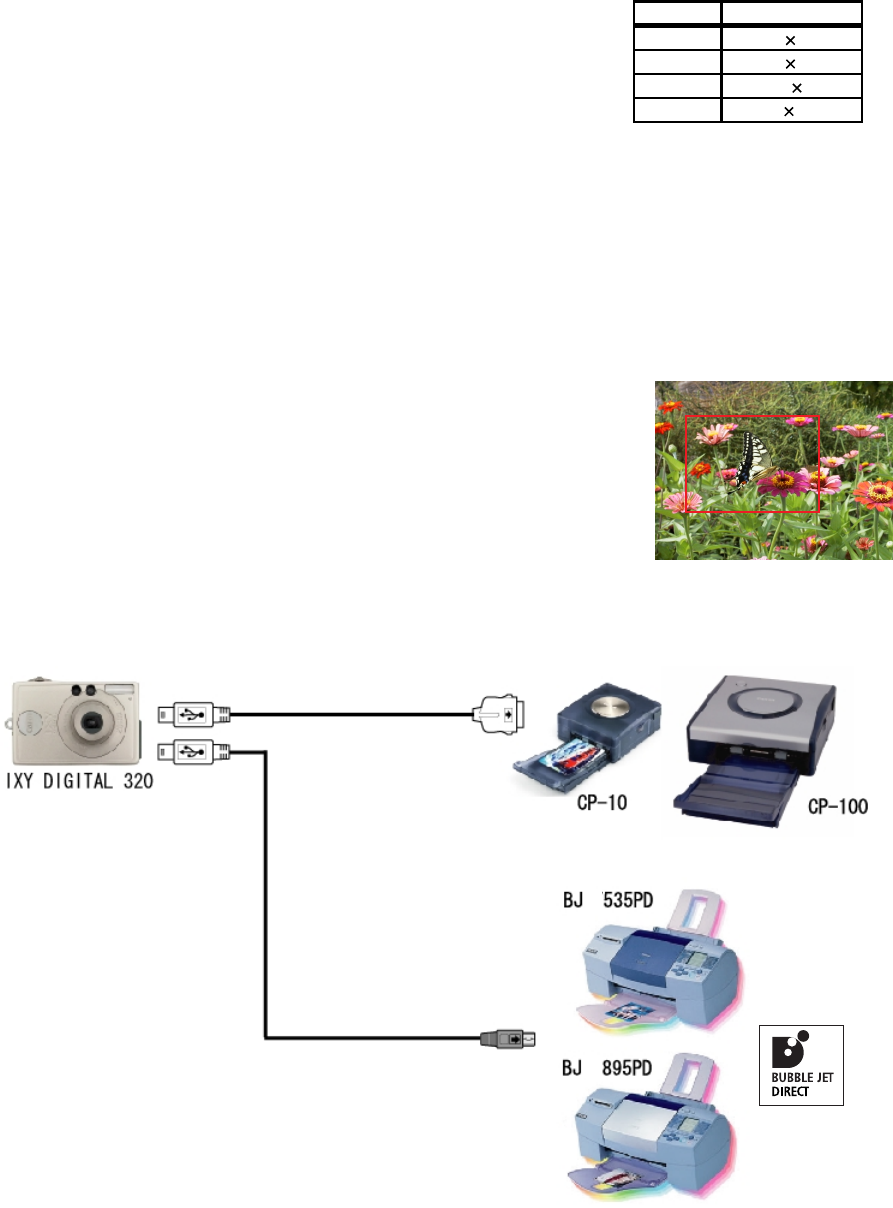
- Direct Print function with cropping capability for dedicated printers (card photo printers
CP-100/10) and Bubble Jet printers (BJ 895PD/535PD/F890PD)
The Direct Print function has been added to the IXY DIGITAL 320 so that high-picture-quality prints can be
made easily by merely connecting the camera with the supplied cable to a Canon card photo printer (CP-10/
100) or a Bubble Jet printer (BJ F895PD/BJ F535PD/BJ F890PD). High-quality prints can be readily attained
with the BJ 895PD and BJ 535PD in particular since they support Exif 2.2.
Furthermore, the IXY DIGITAL 320 adds a “cropping” capability
not found on the IXY DIGITAL 200a, which allows the user to expand
and print an area of the image. After selecting the cropping mode, the
section denoted by the frame superimposed over the image displayed
on the LCD monitor can be printed. The size of the frame can be
adjusted in either 8 steps (when placed horizontally) or 5 steps (when
placed vertically) with the zoom lever and the position can be moved
with the cross-configured buttons.
Table 2–1 Recording pixels
Photo 2–2 Cropping window
Figure 2-4 Direct print
Recordin
g
Pixels
Large 2,048 1,536
Medium 1 1,600 1,200
Medium 2 1,024 768
Small 640 480
1-10
2-3 High Image Quality
- 1/2.7-inch CCD with approximately 3.2 million camera effective pixels (total of about 3.3
million pixels)
The IXY DIGITAL 320 is equipped with a newly developed 1/2.7-inch 3.3 million pixel CCD (about 3.2 million
camera effective pixels). The pixel pitch of this CCD is 2.575mm by 2.575mm, achieving a huge 39 percent size
reduction in the area ratio of the chip when compared to conventional 1/1.8-inch three-megapixel-class CCDs
(found on the PowerShot G1/S30). Because of this, it is possible to appropriate the optical system and body of
the previous IXY DIGITAL 200a, resulting in an ultra-compact three-megapixel-class digital camera.
- High definition and fast processing with the newly developed “DIGIC (Digital Imaging Processor)”
The IXY DIGITAL 320 comes equipped with the “DIGIC (Digital Imaging Processor)”, a newly developed
image processor. DIGIC (Digital Imaging Processor) achieves enhanced high picture quality by improving
signal processing algorithms as the
successor of prior processor.
The following* are the main advances
of the DIGIC (Digital Imaging Processor).
• Improved picture quality
• Improved AF accuracy
• Improved processing speed
* The DIGIC (Digital Imaging Processor) features
many improvements, but the three
points above are the principle
contributions to the Ixy digital 320.
- VGA-size movies that achieve higher picture quality
The new 3-megapixel CCD of the IXY DIGITAL 320 can read 1 line of every 3 lines in the lengthwise
direction due to a change in the electrode structure (charge reading method). Because of this innovation, a
moving image with 524 lines per frame can be created resulting in a huge step forward in quality in comparison
to VGA-size movies of previous models (pixel interpolation* types).
However, with the increase in the number of CCD pixels, the frame rate is reduced to 15 frames per second
from the IXY DIGITAL 200a’s 20 frames per second.
Lens/CCD DIGIC
(Digital Imaging
Processor)
Flash
PROM
CPU
LCD
CF
Card
SDRAM
USB
VIDEO
AUDIO
Figure 2–5 Block diagram
1-11
2–4 System Accessories/ Application Softwares
- Full featured application software
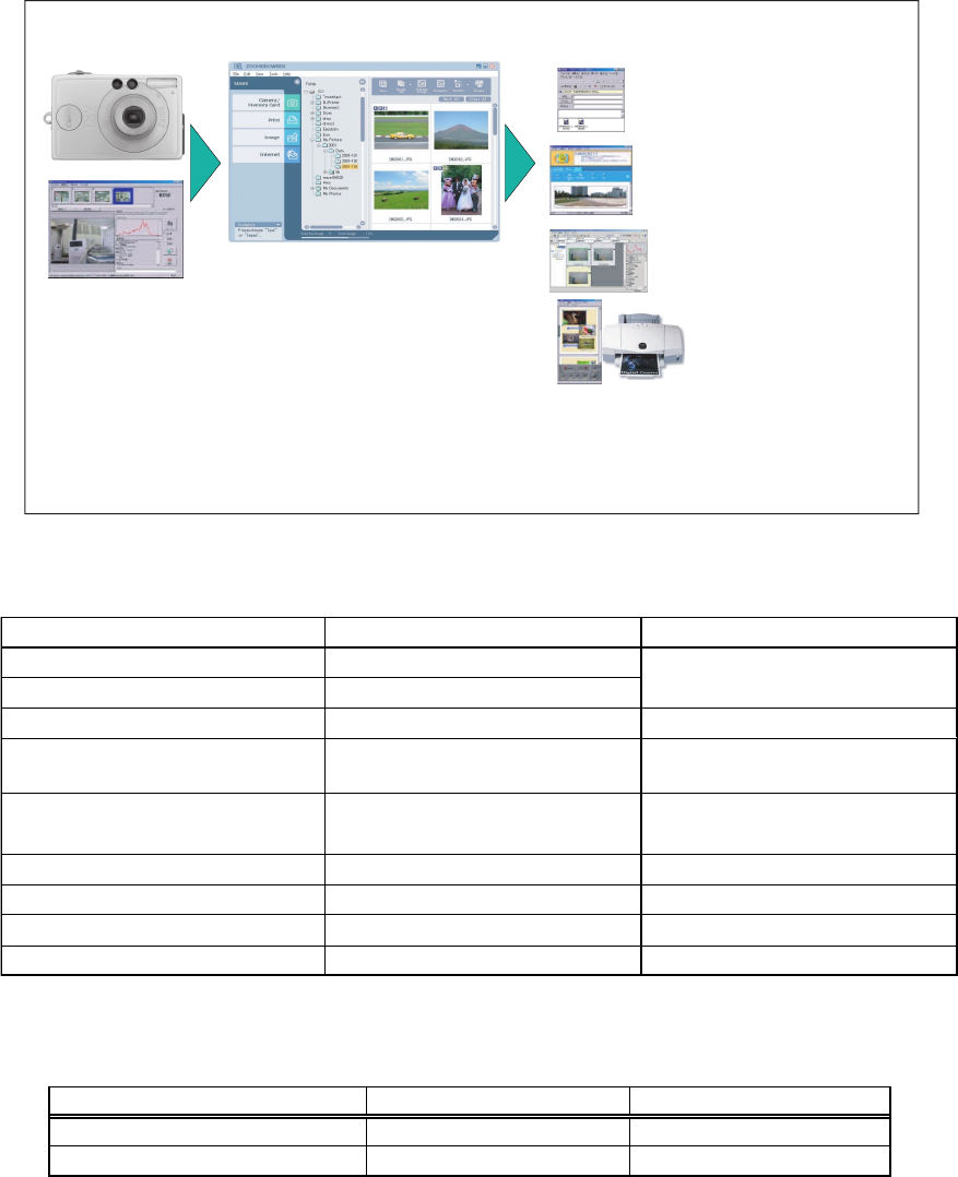
Figure 2–6 illustrates the general organization of the application software bundled with the IXY DIGITAL 320.
Tables 2–2 and 2–3 list the content of each CD-ROM disk.
Figure 2–6 Organization of bundled applications
Table 2–3 Bundled software content 2
Table 2–2 Bundled software content 1
Windows Macintosh
Image processing & editing (Still) ArcSoft PhotoImpression 4.0 ArcSoft PhotoImpression 4.0
Image processing & editing (Movie) ArcSoft VideoImpression 1.7 ArcSoft VideoImpression 1.6
ZoomBrowser
RemoteCapture
PhotoStitch
PhotoRecord
File Viewer Utility
PhotoStudio/VideoImpression
(ImageBrowser)
Remote controlled image capturing
Image import
Image management
Mail
Composition
Printing
Development for
RAW image
Processing & Editing
Windows Macintosh
ZoomBrowser EX 4.0
Prints for arranged images PhotoRecord 1.6
Composition of images PhotoStitch 3.1 PhotoStitch 3.1
Remote controlled image capturing
& export RemoteCapture 2.6 RemoteCapture 2.6
TWAIN Driver 5.0
WIA Driver 5.0
File Viewer Utility 1.0 File Viewer Utility 1.0
Apple Quick Time 5.0 -
CP-100/10 Printer Driver 2.1 CP-100/10 Printer Driver 2.1
for Printer driver's manual Adobe Acrobat Reader 4.0 Adobe Acrobat Reader 4.0
ImageBrowser 2.7
USB Mounter 1.8
Image management & display
Camera driver
Development for RAW image
Movie playback
Printer driver
1-12
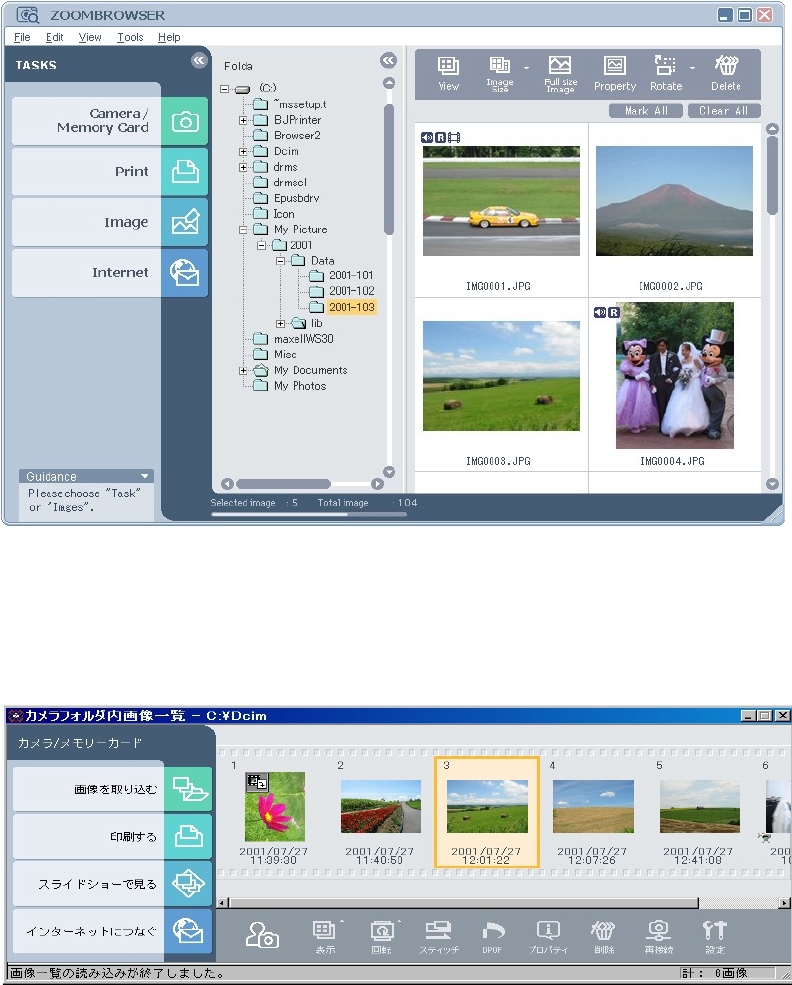
{ZoomBrowser EX 4.0 (Win) made more ergonomic
The ZoomBrowser EX 4.0 makes a vast improvement in usability from previous ZoomBrowser EX versions,
featuring an updated user interface. (The previous ImageBrowser Ver. 2.7 is bundled for use with Macintosh
computers.)
Figure 2–7 Main ZoomBrowser EX screen
Figure 2–8 Image listing in ZoomBrowser EX (Japanese version)
1-13
Main improvements
1) Speed improvements
Changed to lighter, more compact database files
• Shorter launch time
• Quicker camera downloads
• Quicker thumbnail display of new images
• Shorter image delete and copy times
2) Improved database file reliability
• Revamped database construction
• Database is separated and saved as folders
3) File maintenance function improvements
Images displayed by selecting arbitrary folders
• Previous image folder registration operation unnecessary
Automatic update of image display
• Actual image file is checked automatically when displaying images within a folder
4) Unification of user operation procedures
Larger buttons make primary functions into explicit tasks
Unified task procedures
• All steps of an operation are shown and the current step is indicated
• Step-to-step operation works in Wizard fashion
Automatic selection of camera connection
• Same button is pressed for either camera connections or card reader connections
Other improvements in the user interface
1) Zoom mode, scroll mode, tool buttons
2) Easy-to-understand selection of multiple images
Multiple images are selected by repeating a single click (default setting)
3) Property window
Displays information on the selected image
Possible to add and select with floating windows
Other improvements
1) Addition of function to save the camera’s My Camera settings on computer
2) Installer converted to Windows Installer
Improved localization workability
Discontinued functions
1) Deleted TWAIN interface
Eliminates automatic launch problem with Windows Me
2) Deleted TimeTunnel viewer
3) Support for 256 screen colors discontinued
1-14
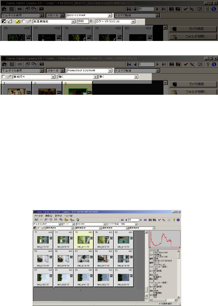
{File Viewer Utility 1.0 (support for Mac OS X at a later date)
From this release on, File Viewer Utility will be included in place of the previous RAW Image Converter
The following are the main functions and features:
1) Parameters for RAW images such as white balance, contrast, color intensity and sharpness can
be set
2) User interface supports all camexras regardless of common interfaces
3) Possible to select various image display methods
“Thumbnail/Preview/JPEG Preview” X “Large/Medium/Small”
4) Fast preview of RAW images
Fast previews taking advantage of JPEG images without developing RAW images
5) Various displays
RGB at cursor position
6) Extension of viewable formats
File formats generated by cameras (JPEG-DCF, RAW)
File formats generated by File Viewer Utility (TIFF-Exif, TIFF 16 bit)
<EOS DIGITAL type>
<PowerShottype>
Figure 2–9 Parameter setup window
Figure 2–10 Main File Viewer Utility screen
1-15
{PhotoRecord 1.6 (Win) for easy layout and printing of clear pictures
Adds support for Exif 2.2 to previous version
{PhotoStitch 3.1 for creating precise panoramic pictures
Unchanged from previous version in terms of usability
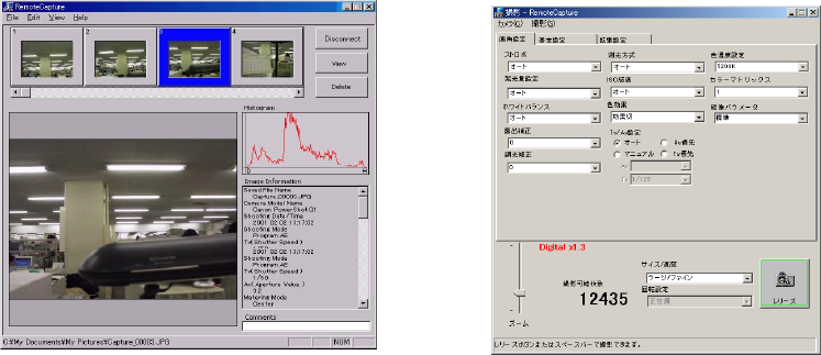
{RemoteCapture 2.6 for image captures and image transfers controlled from computer
The following are the changes from the previous version:
1) Moved to software without device information to support new firmware and new SDKs
Abandoned device-specific recording windows and made one window for all devices
2) Added specifications
Enhanced manual setting items (M, Av, Tv, AE selection, flash strength setting, flash exposure
compensation setting)
{TWAIN Driver 5.0/WIA Driver 5.0 (Win)
Function limited to importing PEG images
{USB Mounter 1.6 (Mac, however only supports OS 9 to OS 9.2)
Unchanged from previous version in terms of usability
{Apple QuickTime 5.0 (Win)
Unchanged from previous version in terms of usability
{CP-10/100 PrinterDriver 2.1
Adds support for CP-100 from this release on
{Adobe Acrobat Reader 4.0
Bundled for use with printer driver PDF manuals
Figure 2–11 Parameter setup window
in RemoteCapture Figure 2–12 Main RemoteCapture screen
1-16
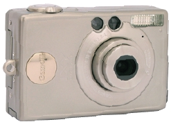
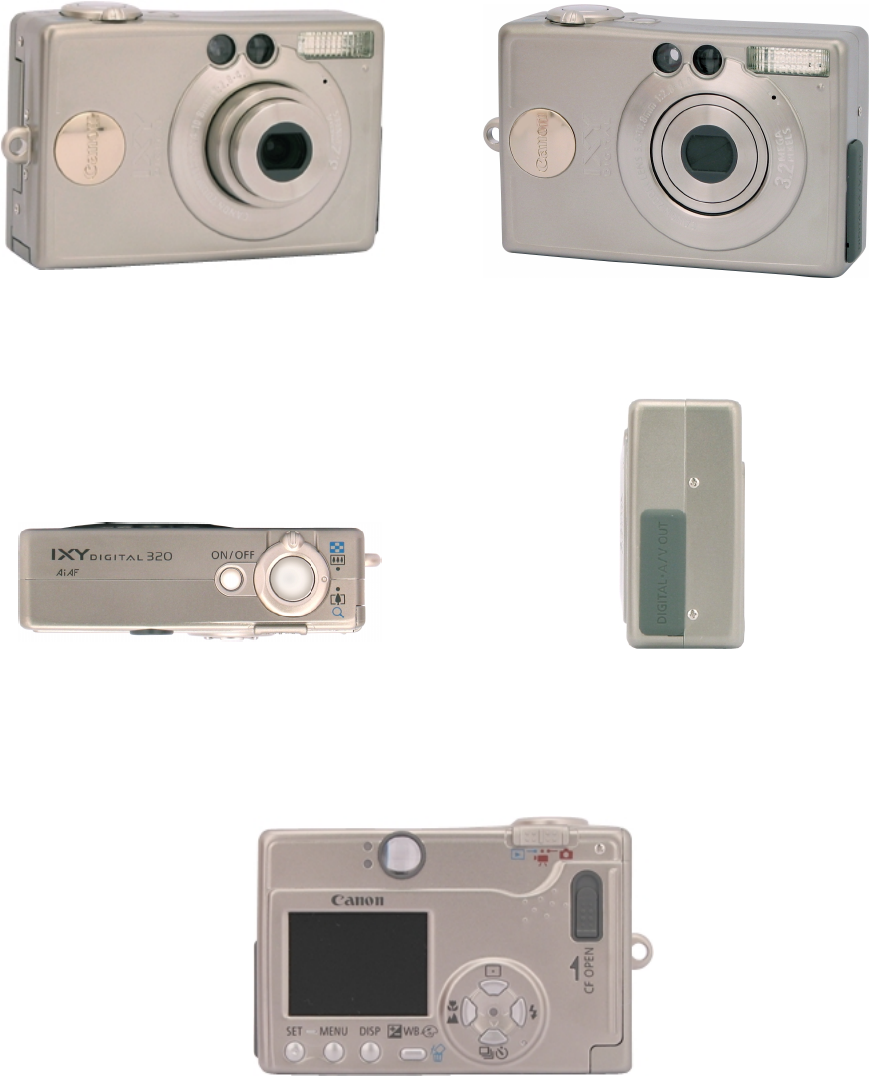
Photo 3-1 IXY DIGITAL 320 Front
(Opend lens)
Photo 3-2 IXY DIGITAL 320 Front
Photo 3-3 IXY DIGITAL 320 Top
Photo 3-4 IXY DIGITAL 320 Side
Photo 3-5 IXY DIGITAL 320 Rear
3 Exterior
3-1 Exterior Photos
1-17
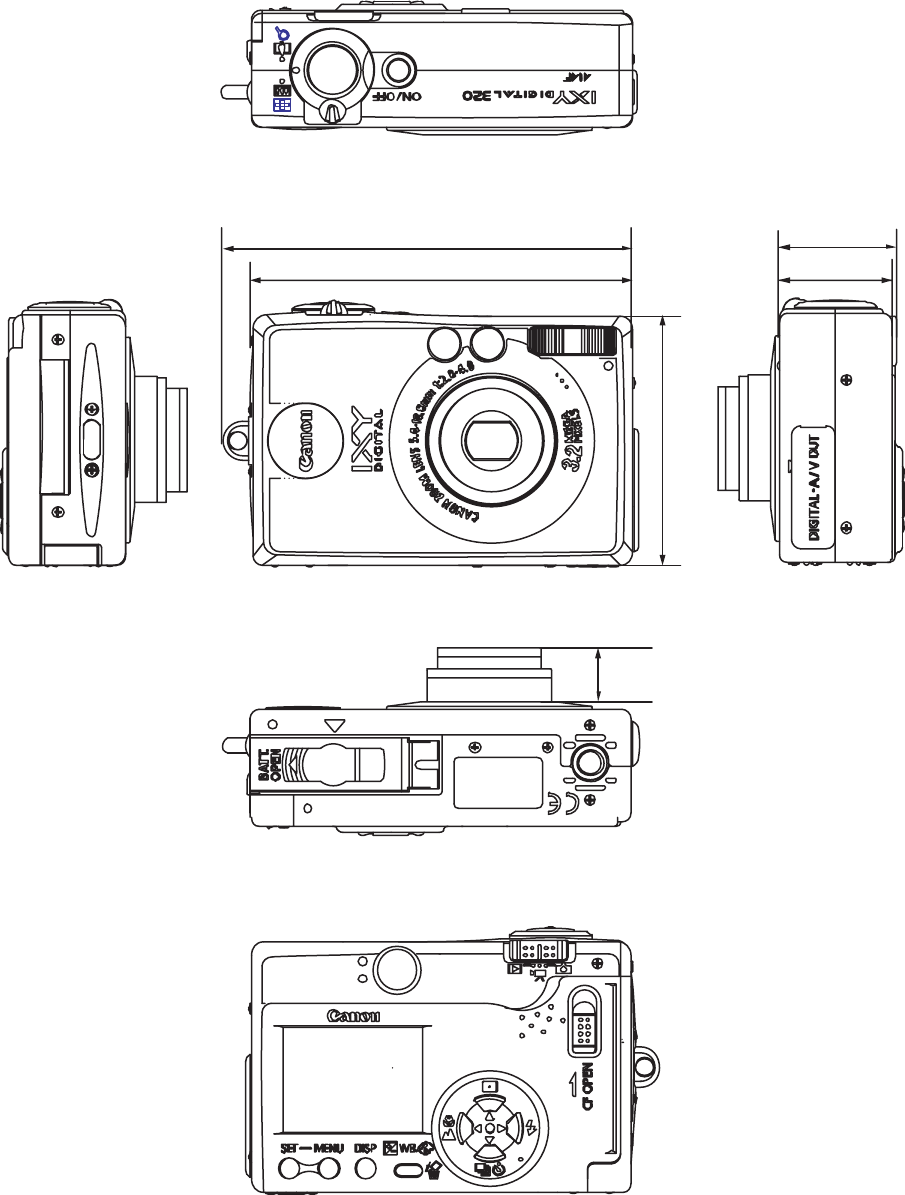
3-2 6-dimensional diagram
unit : mm (inch)
87.
0 ( 3. 43) 25. 8( 1. 02)
26. 7( 1. 05)
93. 5 ( 3. 68)
57. 0( 2. 24)
W
i de : 12. 3 ( 0. 484)
Te
l e : 12. 1 ( 0. 476)
1-18
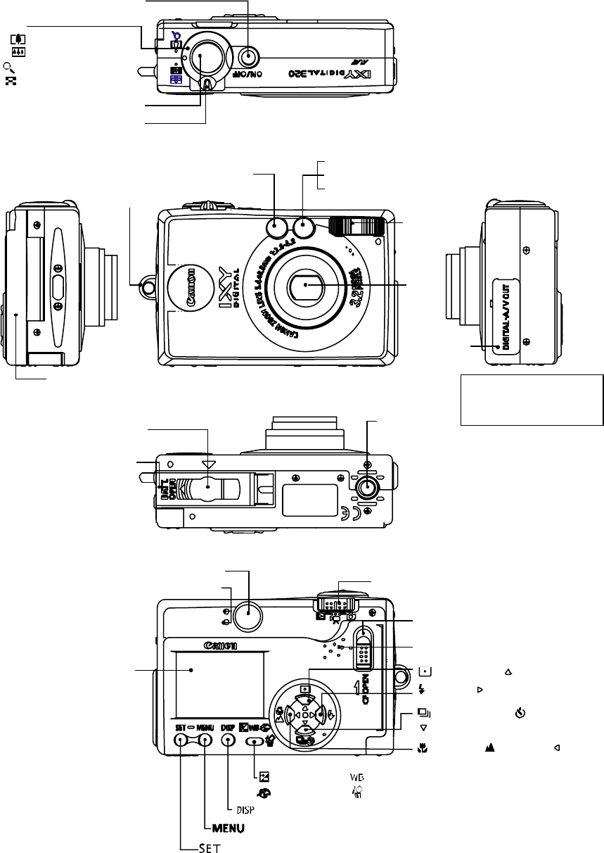
3-3 Nomenclature
Lens
/Lens Cover
Viewfinder eyepiece
Indicators
Speaker
CF Card Slot Cover
LCD Monitor
Lock for the CF Card Slot Cover
Flash
Terminal
Cover
Optical Viewfinder Window
ON/OFF Button
Strap Mount
Shutter Button
Zoom Lever
AF-assist Beam
Red-Eye Reduction Lamp
Self-Timer Lamp
Tripod Socket
DC Coupler Terminal Cover
Battery Cover
(
Menu)Button
(
Display
)
Button
(Set) Button
(
Exposure
)
/
(
White Balance)
(
Photo Effect
)(
Erase
)
Button
(
Flash)/ Button
(
Continuous
)
/
(
Self-timer)/
Button
(
Macro)/
(
Infinity )/ Button
(
Metering )/Button
Mode Switch
Zoom Button
Shooting
:
(Telephoto
)
(
Wide Angle
)
Replay
:(
Magnifying
)
(
Index
)
DIGITAL Terminal
A/V OUT Terminal
(
Inside of Terminal Cover
)
1-19
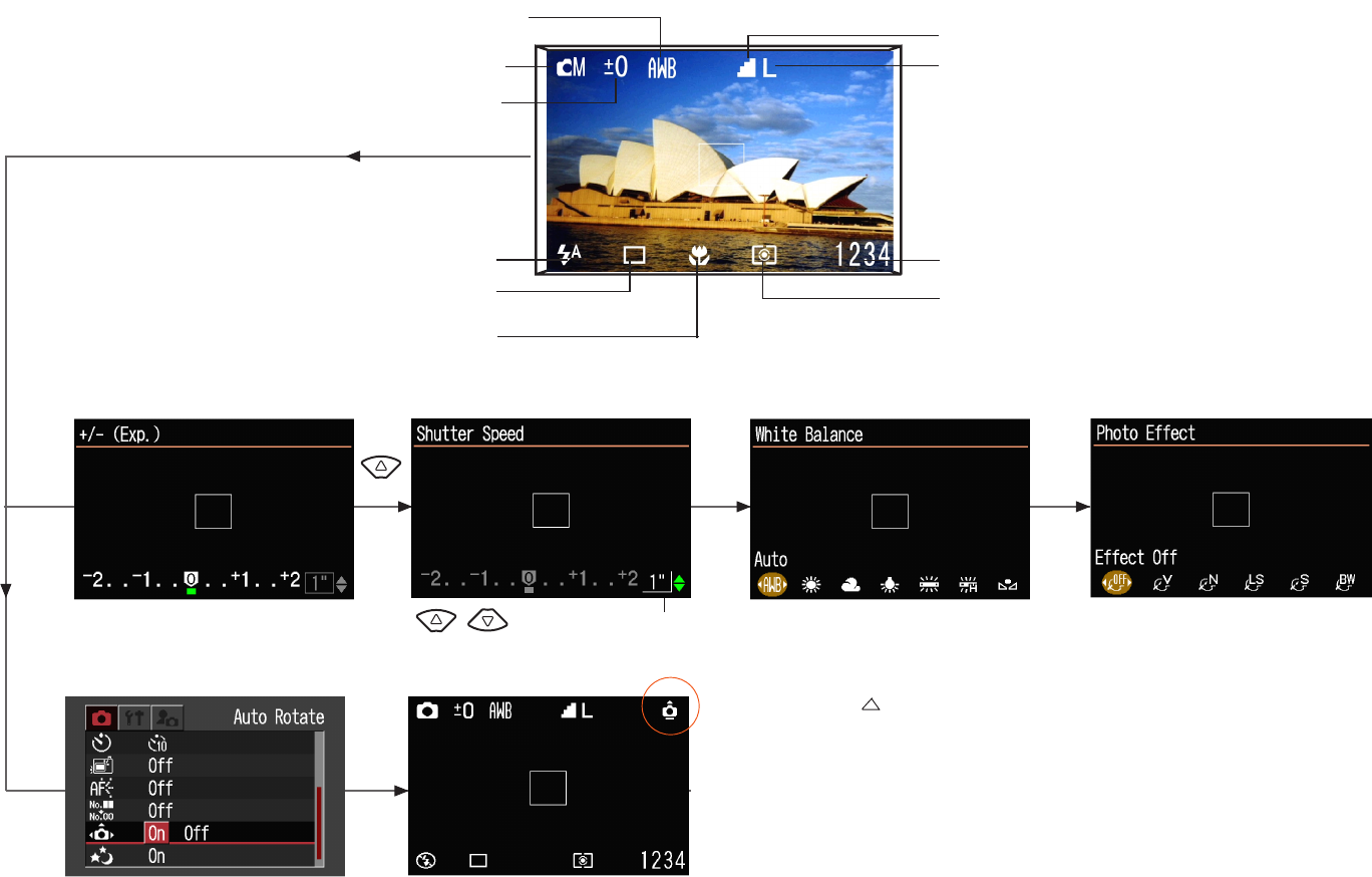
Remaining Image Capacity
Shooting mode
White Balance
Resolution
Macro
Compression
Exposure Compensation
Flash
Single Shot Light metering method
<Auto Rotate>
<Exposure Compensation> <Shutter Speed>
<Screen for shooting>
<White Balance>
Auto /Daylight /Cloudy / Tungsten /
Fluorescent / Fluorescent H / Custom
<Photo Effect>
Effect Off / Vivid / Neutral /
Low Sharpening / Sepia / B/W
set up with a button.
The direction which has turned to is judged to be
"up", and it is rotated and displayed in the correct
vertical position in playback mode.
WB WB WB
MENU
3-4 UI Information
-Screens for Shooting
1-20
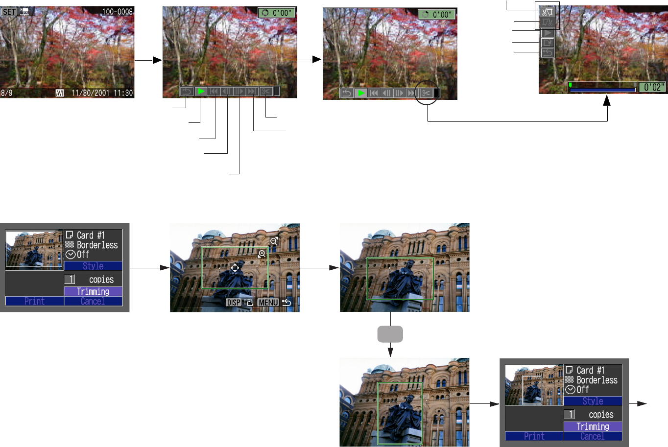
-Setting the Printing Area (Trimming)
DISP
Zoom Lever and Cross Configured
button adjust the size and position of
the Trimming frame.
Print
-Editing Movies
Return to Single
Image View Play
Previous Frame/Rewind
Next Frame/Fast Forward
Switch to Movie Editing Mode
Last Frame
First frame
Cut beginning
Close Movie Editing/
Return to Movie ControllPanel
Play
Save
Cut End
Edit
SET SET
1-21
4 Specifications
4-1 Camera Specifications
Image sensor (CCD)
Camera effective pixels (W x H) Approx. 3.2 million (2,080 x 1,542)
Total pixels (W x H) Approx. 3.3 million (2,140 x 1,560)
Reading format Interline
Chip size (W x H) 1/2.7-inch size 5.36 x 4.05 mm (0.21 x 0.16 inch)
Unit cell size (W x H) 2.575 x 2.575 micron
Filter array Primary color filter (Beyer)
Lens
Focal length 5.4 (W) - 10.8 (T) mm
(35mm film equivalent : 35 (W) - 70 (T) mm)
f/number F2.8 (W) - 4.0 (T)
Lens construction 7 elements in 5 groups (including 3 aspherical lens)
Optical zoom 2x
Shooting distance Normal AF : 47 cm (1.5 ft.) - infinity
(Measured from tip of the lensbarrel) Macro AF : 10 - 47 cm (0.33 x 1.5 ft) (W)
27 - 47 cm (0.89 x 1.5 ft) (T)
Landscape : 5.0 m (17 ft.) - infinity
Max. shooting area (W x H) Wide : 102 x 76 mm (4.0 x 3.0 inch)
Tele : 138 x 103 mm (5.4 x 4.1 inch)
Optical viewfinder
Type Real-image optical zoom viewfinder
Coverage Vertical : 82 % Horizontal : 82 %
Eyepoint 16 mm
1-22
LCD monitor
Type Low-temperature polycrystalline silicon TFT color LCD
Effective pixels (W x H) Approx. 118 K- Pixels (490 x 240)
Display size 38 mm diagonal (1.5 inch)
Coverage 100 %
Focusing
Control system TTL AiAF/TTL AF
(AF lock is available: By pressing the shutter button halfway)
Focusing point 9 points (TTL AiAF) / 1 point on center (TTL AF)
Exposure control
Metering modes Evaluation (AF point linked) / Spot
Exposure control system Program AE (AE lock is available.)
Exposure compensation +/- 2 stops in 1/3-stop increments
Sensitivity Auto / ISO 50/100/200/400 equivalent
(Equivalent film speed)
White balance
Mode TTL auto white balance / Pre-set white balance (Daylight /
Cloudy / Tungsten / Fluorescent / Fluorescent H) / Custom
white balance

1-23
Shutter and aperture
Shutter type Mechanical shutter and electronic shutter
Aperture type Round shaped diaphragm
Shutter speed 15 - 1/1,500 sec.
y1/6 - 1 sec. shutter speed is only available with the flash
off or slow sync. at Manual mode.
y1 - 15 sec. is available with button in long shutter
mode at Manual mode.
f/number F2.8/7.2 (W), AF4.0/10.0 (T)
Flash (Built-in)
Operation mode Autoflash / Red-eye reduction auto / Flash On/Flash Off /
Slow-syncro.
Flash range (When sensitivity is set to ISO 100 equivalent.)
Normal : (W) 47cm - 3.0 m (1.5 - 9.8 ft.)
(T) 47cm - 2.0 m (1.5 - 6.6 ft.)
Macro : 27 - 47cm (0.89 - 1.5 ft.)
Flash sync speed 15 - 1, 1/60 - 1/500 sec.
Recycling time 10 sec. or shorter (full flash, battery voltage = 3.7V)
Flash exposure compensation +/- 2 stops in 1/3-stop increments
Functions FE lock

1-24
Shooting specifications
Shooting modes Auto / Manual / Stitch assist / Movie
Shooting function
Digital zoom Maximum 3.2x (Maximum of approx. 6.4x zoom is available
when combined with optical zoom.)
Photo effects Vivid color / Neutral color / Low sharpening / Sepia / Black &
White
Noise reduction When shutter speed is set between 1.3 - 15 sec. .
Rec-review Off, 2 - 10sec. (Can be set to each 1 sec. unit)
Camera power-up time
/ Release time lag
* Varies with shooting modes
Shooting interval
* The actual shooting interval is the shutter speed added to the
above data.
Continuous shooting
Number of shots per second Approx. 2.0 images / sec.
(Large (2048 x 1536) / Fine mode and LCD viewfinder is Off)
Maximum burst
yThe above data is the maximum with each “resolution /
compression” mode. (64 is the maximum)
yWhile achieving the maximum number of shots, continuous
shooting is available. However burst speed will go down.
Self-timer Operates with approx. 2 sec. or approx. 10 sec. countdown.
Shutter release from PC Use of “RemoteCapture” software (enclosed) during USB
camera connection.
Mode Finder
Camera
power-up
time (sec)
LCD monitor On
LCD monitor Off
-
2.8
1.9
2.2
Shutter time
lag (sec)
0.07
0.05
-
Shooting
Replay
Shooting
Mode Finder
LCD monitor On
LCD monitor Off
N/M
Normal
Macro
AF Lock
Normal
Macro
Lens
Psition
Wide
Tele
Wide
Tele
Wide
Tele
Wide
Tele
Shooting Interval
(sec)
2.1
2.2
2.7
2.2
1.7
1.7
1.8
2.1
1.8
Auto
Resolution/
Compression rate
Maximum number of
shots
L/SF
7
L/F
12
L/N
23
M1/SF
11
M1/F
19
M1/N
37
M2/SF
18
M2/F
32
M2/N
60
S/SF
41
S/F
64
S/N
64
1-25
Recording specifications
<Still image>
File format Design rule for Camera File system
Digital Print Order Format (DPOF) Version 1.1 compliant
Image recording format JPEG (Exif 2.2)
JPEG compression mode Super fine / Fine / Normal
Number of recording pixels Large : 2048 x 1536 Middle1 : 1600 x 1200
Middle2 : 1024 x 768 Small : 640 x 480
Recording capacity
<Movie>
File format AVI
Recording format Image : Motion JPEG, Audio : FWAVE (Monaural)
Number of recording pixels VGA : 640 x 480 QVGA : 320 x 240 QQVGA : 160 x 120
Frame rate / Shooting time
Recording time*
* FC-256MH : There is some area which is not sold.
* The above-written figures are measured under Canon’s testing
standard and may very depending on the scene, subjects or
camera settings.
<Common>
Storage media CompactFlashTM (CF) card (Type I)
Tone reproduction JPEG : Luminance signal : 8 bits/Color signal (Cr/Cb) : 8 bits
L/SF L/F L/N M1/SF M1/F M1/N M2/SF M2/F M2/N S/SF S/F S/N
1602 KB 893 KB 445 KB 1002 K B 558 KB 278 KB 570 KB 320 KB 170 KB 249 KB 150 KB 84 KB
48167
14
13 26 12 23 42 29 47 83
81632 26522546845894165
18 33 67
136
274
548
30 54 108 53 94 174 120 196 337
38 68 61 109 217 107 189 349 241 393 676
76 137 122 219 435 215 379 700 482 788 1355
154 276 246 440 868 431 762 1390 962 1563 2720
File Size
FC-8M
FC-16M
FC-32M
FC-64M
FC-128M
FC-256MH
Frame rate (fps)
15
15
15
640 480
320 240
160 120
Shooting time (min)
30
180
180
320 240
File Size 330 KB/sec
FC-8M 22"
FC-16M 44"
FC-32M 91"
FC-64M 183"
FC-128M 368"
FC-256MH 735"
640 480
990 KB /s ec
7"
14"
30"
61"
124"
249"
160 120
120 KB /s ec
59"
118"
242"
486"
973"
1954"
1-26
Replay specifications
Replay mode Single / Index (9 thumbnail images) / Magnification / Movie
<Still image>
Magnify Approx. 2 - 10x
Vertical and horizontal Images are displayed vertically or horizontally according to the
conversion camera’s shooting position. Also, vertical and horizontal
conversion can be set for each image.
(Both LCD monitor and Video out play the image according to
setting.)
Histogram display Display luminance allocation of image.
(available on rec-review.)
Slide show Interval between shots : 3 - 10 sec. 15 sec. 30 sec.
Manual setting
Repeat : On / Off
DPOF Print order/Slide show/Image transfer
Direct print Image output to dedicated printers (CP-100, CP-10) and BJ
printer (BJ 895PD, 535PD, F890PD).
<Movie>
Special replay Next frame / Previous frame / Fast forward / Rewind /
First frame / Last frame
Erasing specifications
Erasing modes Still images: Single image / All images
Movie : Part of images * / All of images
The image data recorded on Design rule for Camera File
system’s format can be erased. However, protected images
can’t be erased.
* Can be erased from start-point to mid-point or from mid-
point to end-point with the movie editing function.
Furthermore, frames can be erased both from start-point
to mid-point and from mid-point to end-point
simultaneously.
Protection Erase prohibited (Setting at replay mode)
1-27
Display specifications
Indicator (Upper) Green :
Ready to record / Ready to communicate
(during a computer connection)
Blinking Green :
During power-up camera / Recording to CF card / Reading
CF card / Erasing from CF card / Transmitting data
(during a computer connection)
Orange :
Ready to record (at Flash On)
Blinking Orange :
Ready to record (camera shake warning)
Indicator (Lower) Yellow :
Macro mode / Landscape mode / Focus lock
Blinking Yellow :
Indicates that the focus goes to fixed point because the actual
focus point is not found.
AF-assist beam Lights :
Low-contrast objects, low-light conditions and red-eye
reduction on while SW1 on.
Blinks :
During count down of self-timer.
The AF-assi st Beam blinks at 2 Hz for the first 8 seconds and at
8 Hz for the last 2 seconds (9th and 10th seconds) and then turns
off. (If the red-eye reduction is on, it lights instead of blinking for
the last 2 seconds.)
Power mode indicator Green: Power On
Beep Single sound (twice) : Ready to record
Single sound (once) : Button operations, complete shooting
(shutter off) and warning of off-focus.
Single sound (6 times) : Warning (CF card full or not inserted
in camera)
Continuous sound : Warning (CF card slot cover / battery
cover was opened while recording to CF
card.)
Intermittent sound : Count-down of self-timer.
* Sounds (excluding when CF card slot cover/battery cover is
open and CF card is not inserted in camera) can be set on or off.
Interface
Computer I/F USB * : Normal / PTP
A/V out Video : NTSC/PAL
Audio : Monaural
1-28
Others
Languages 12 languages are available for menu and messages.
English, German, French, Dutch, Danish, Finnish, Italian,
Norwegian, Swedish, Spanish, Chinese and Japanese
Power supplies
Power sources Rechargeable Lithium-ion battery (type: NB-1LH, NB-1L)
AC adapter AC adapter (type: CA-PS500)
* DC coupler (type: DR-500) is required.
Car battery adapter Car battery adapter (type : CBC-NB1 <optional>)
Sub-battery Unremoval
Shooting capacity NB-1LH (full charge) :
LCD monitor On : Approx. 170 images
LCD monitor Off : Approx. 420 images
Normal temperature (23°C). LCD vi ewfinder is On. Shoot
images at wide angle and at telephoto end alternately with
20 seconds intervals.
Use flash at every 4-time shooting. Turn camera off and
on at every 8-times s hooting.
Replay time NB-1LH (full charge): Approx. 130 min.
Canon’s standard conditions of mesuring replay time are as follows:
Normal temperature (23°C). Repeat replay automatically at
a speed of 1 image per 5 seconds.
Charging time Approx. 130 min. (CB-2LS)
Power-saving function Power-saving function is active with demanding on each mode
when power-saving on the menu screen is “on”.
<Shooting mode>
Powers down approximately 3 minutes after a control is last
accessed.
(The LCD monitor will shut off approcimately 3 minutes
after a control is last accessed even if the power-saving
function is turned off.)
<Replaying mode>
Powers down approximately 5 minutes after a control is last
accessed.
<Printer connection>
Powers down approcimately 5 minutes after a control is last
accessed on the camera or something is printed on the printer.
<PC connection>
Displays a warning message on the computer screen
approximately 5 minutes after a control is last accessed. The
camera will be powered down if no controls are used after 1
additional minute.
(Available only when the communication setting is set to
“normal” and power-saving function is “on”.)
1-29
Camera specifications
Operating temperature 0 - 40°C
Operating humidity 10 - 90 %
Dimensions (W x H x D) 87.0 x 57.0 x 26.7 mm (3.4 x 2.2 x 1.1 inch)
(Excluding protrusion)
Weight Approx. 180 g (6.35 oz) (Excluding batteries and CF card)
1-30
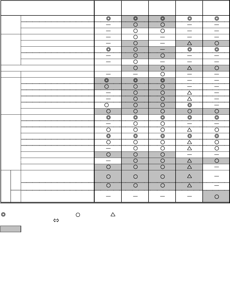
Functions Available in Each Shooting Mode
Auto Manual Manual
(long shutter) Stitch Assist Movie
AF frame: 9points (AiAF)
AF frame: 1point (center)
AF lock
Spot AE point
Exposure control
ISO speed (AUTO)
ISO speed (50/100/200/400) *2 *2
AE lock
Auto only
Shutter Tv value setting
Red-eye reduction ON *3
Autoflash *3
Slow -sync.
On
Of f *3
AF assist beam
Single shot
Continuous
Self-timer (10/2 sec.)
Normal shooting
Macro shooting
Infinity shooting
Digital z oom
Photo effect
Vertical and horizontal conversion
Recording pixels
(L/M1/M2/S)
Compression (SF/F/N)
Recording pixels
(VGA/QVGA/QQVGA)
Functions that are available or unavailable in all modes are not described in the upper table.
: Values saved even after shutdown are remembered.
*1 Evaluation m etering is the default.
*2 ISO 50 is the default.
*3
*4 The setting of vertical and horizontal conversion is effective.
*5 Large is the default.
*6 Fine is the default.
*7 QVGA is the default.
Only the red-eye reduction and auto are saved in auto mode. (Then shutdown with the flash off,
system starts up with the previous flash mode which was selected red-eye reduction or auto.)
: Default (set by mode change) : selectable : selectable only for the first image
Focus
Ex p o s u r e
control
Rec o Sti
rding ll
spec
if icat Mo
ions vie
White balance
Shooting
specifi-
cations
Flas h
Valies saved even PLAY REC are remembered.
1-31
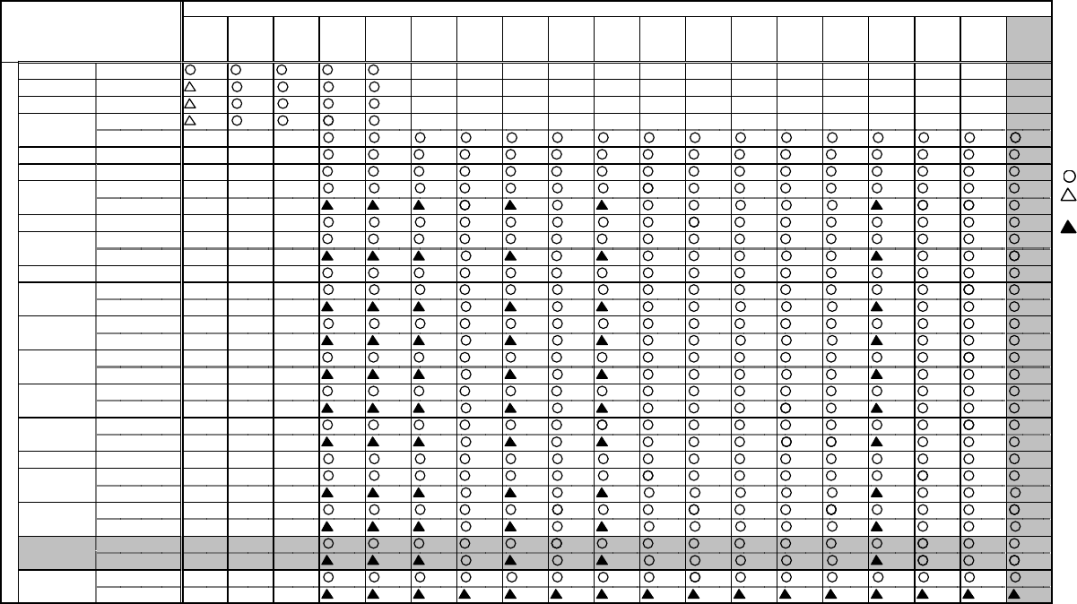
: Replayable
: Impossible to replay
RAW images
: Thumbnail display
AVI main image with
thumbnail (.thm) only
×: Not replayable
IXY DIGITAL 320 supports
3200(H) x 2400(V) pixels.
zReplay compatibility
*1: Thumbnail display of RAW mode images.
*2: Thumbnail display of RAW mode images. JPEG file replay up to 1,024 x 768 pixels.
*3: Only JPEG file replay.
Replayable up to 1,632 x 1,232 pixels. With images larger than the thumbnail display
(160 x 120) size, the “Image too large” message is displayed.
*4: Only JPEG file replay.
Replayable up to 3,200 x 2,400 pixels. With images larger than the thumbnail display
(160 x 120) size, the “Image too large” message is displayed.
*5: “Image too large” message is displayed when the file size exceeds fixed capacity.
*6: “Corrupted data” message is displayed when a movie’s play time exceeds time limit.
Since the following camera’s RAW function has an internal JPEG file for playback, a full screen
image is displayed. However, if the RAW images from the PS A50 and previous models are
played back with the following camera, thumbnails will be displayed.
* PS G1/G2/G3/S30/S40/S45/Pro90 IS, EOS D30/D60/1D
PS
350
PS
A5/
A5 Z
PS
Pro70
PS
A50
PS
S10/
S20
IX Y
DIGITA L
PS
G1,
Pro90 IS
EOS
D30
IX Y D
200/
300
PS
A 10/
A20
PS
G2
PS
S30/
S40
PS
A 40/
A30
PS
A 200/
A 100
ID
200a/
300a
EOS
D60
PS
S45
PS
G3
IX Y D
320
PS 350 CIFF ××××××××××××××
PS A 5/A 5 Z CIFF *1 *1 *1 *1××××××××××××××
PS Pro70 CIFF *2 *1 *1 *1××××××××××××××
CIFF *2 *1 *1 *1××××××××××××××
DCF ××× *1 *1 *1 *1 *1 *1 *1 *1 *1 *1 *1 *1 *1 *1 *1 *1
PS S10/S20 DCF ××× *3
IX Y D IG IT A L DC F ×××
DCF (S till) ××× *1*3 *1 *1 *1 *1
(Movie) ××× *5 *5 *5 *5
EOS D30 DCF ××× *1*3 *1 *1 *1 *1
DCF (S till) ×××
(Movie) ××× *6 *5*6
PS A 10/A 20 DCF ×××
DCF (S till) ××× *1*3 *1 *1 *1 *1
(Movie) ××× *5*6 *5*6 *5*6 *5*6 *5*6
DCF (S till) ××× *1*3 *1 *1 *1 *1
(Movie) ××× *5*6 *5*6 *5*6 *5*6 *5*6
DCF (S till) ×××
(Movie) ××× *6 *5 *5*6
DCF (S till) ×××
(Movie) ××× *6 *5
DCF (S till) ×××
(Movie) ××× *6 *5*6
EOS D60 DCF ××× *1*3 *1 *1 *1 *1
DCF (S till) ××× *1*3 *1 *1 *1 *1
(Movie) ××× *5*6 *5*6 *5*6 *5*6 *5*6 *5*6 *5*6 *5*6
DCF (S till) ××× *1*3 *1 *1 *1 *1
(Movie) ××× *5*6 *5*6 *5*6 *5*6 *5*6 *5*6 *5*6 *5*6
DCF (S till) ××× *3
(Movie) ××× *5*6 *5*6 *5*6 *5*6 *5*6 *5*6 *5*6
DCF (S till) ××× *3 *4 *4 *4 *4 *4 *4 *4 *4 *4 *4 *4 *4 *4 *4 *4
(Movie) ×××
ID 3 2 0
Other DCF
cameras
Replay cameras
I
m
a
g
e
t
a
k
I
n
g
c
a
m
e
r
a
s
PS A 50
PS G2
PS S30/S40
PS A 40/A 30
PS A 200/A 100
ID 200a/300a
PS S45
PS G3
PS G1
PS Pro90 IS
IX Y D IG IT A L
200/300

1-32
4-2 System Requirements
Windows Macintosh
Computer Model IBM PC/AT compatible Power Macintosh, PowerBook, iMac, iBook
OS
Windows 98 (including Second Edition)/Me/2000/XP
- TWAIN Driver is compatible with Windows 98/2000.
- WIA Driver is compatible with Windows Me/XP.
Mac OS 8.6 - 9.2 and Mac OS X 10.1
- Mac OS X does not support UFS (Unix File System).
- File Viewer Utility is not supported by Mac OS X.
- USB Mounter is compatible only with Mac OS 9.0 - 9.2.
CPU Windows 98/Me/2000: Pentium 150 MHz or better
Windows XP: Pentium 300 MHz or better PowerPC
Memory
(RAM)
Windows 98/Me/2000: 64 MB or more
Windows XP: 128 MB or more
Mac OS 8.6 - 9.2 : 20 MB or more of application memory
Mac OS X 10.1 : 128 MB or more of RAM
Free hard disk
space
*Capacity for
installation
ZoomBrowser EX 4.0/PhotoRecord 1.6 : 120 MB or more
PhotoStitch 3.1 : 40 MB or more
File Viewer Utility 1.0 : 100 MB or more
RemoteCapture 2.6 : 20 MB or more
TWAIN Driver 5.0 : 25 MB or more
WIA Driver 5.0 : 25 MB or more
CP-100/CP-10 Printer Driver 2.1 : 1 MB or more*
ArcSoft PhotoImpresion 4 : 275 MB or more
ArcSoft VideoImpression 1.7 : 200 MB or more
ImageBrowser 2.7 : 20 MB or more
PhotoStitch 3.1 : 30 MB or more
File Viewer Utility 1.0 : 100 MB or more
RemoteCapture 2.6 : 15 MB or more
USB Mounter 1.8 : 5 MB or more
CP-100/CP-10 Printer Driver 2.1 : 3.8 MB or more*
ArcSoft PhotoImpresion 4 : 275 MB or more
ArcSoft VideoImpression 1.6 : 100 MB or more
USB interface USB: Only preinstalled Windows 98/Me/2000/XP systems
with built-in USB ports.
USB: Only systems equipped with genuine Apple-brand
built-in USB interfaces.
Display 800 × 600 pixels High Color (16-bit) or more required
(1,024 × 768 pixels or more recommended)
800 × 600 pixels 32,000 colors or more required
(1,024 × 768 pixels or more recommended)
Sound card Required to play movie sound
Others Apple QuickTime 3.0 or higher is required to play movies and save/play
QuickTime VR. (Apple QuickTime 5.0 is included.)

1-33
5 System
5-1 Accessories Compatibility
PS G3
I D 200a
I D 300a
I D 320
PS A 200
PS A 100
PS A 40
PS A 30
PS S3 0
PS S4 0
PS S4 5
PS G2 IXY D 200 IXY D 300 PS A 20
PS A 10
IXY
DIGITA L
PS Pr o
90 IS PS G1 PS S1 0
PS S2 0 PS Pr o7 0 PS A 5 Z
PS A 50 PS A 5
<Battery>
NB- 5H ------------O-OO
NB- 4H -------------O--
NB- 1L -O----OO-O- - - - - -
BP-511 O- ---O- - - -OO- - - -
BP-512 O- ---O----------
NB4- 100 --O*
1O----O-------
NB- 2L ----
O
-----------
NB- 1LH -O----OO-O- - - - - -
*1: 2 sets of 2 batteries (4 battery packages).
<Adapter
/C
harger>
C
A-P
S
100
/
100E ------------O-OO
CA-PS200 -------------O--
CA-PS300 ---------O------
C
A-P
S
500 -O--
(
O
)
*2--OO-
(
O
)
*2O------
C
A-560 O- ---O- - - - OO- - - -
CR- 56 0 O- ---O- - - -OO- - - -
CA-PS800 --O- ------------
C
B-2L
/
2LE ---------O------
C
B-2L
S/
2L
S
E-O----OO--------
CB- 3A H --O*
3O----O-------
CBK100 --O*
3O----O-------
C
B-2LT
/C
B-2LTE ----
O
-----------
C
B
C
-NB1 -O----OO--------
CBC- NB2 ----O-----------
*2: It is possible to use by inserting the adapter's DC plug in the jack of PS A40/A30/A20/A10 cameras directly w ithout using DC coupler.
<DC Coupler> *3: 4 batteries (2 set of 2) can be recharged.
DR-100/100A ------------O-OO
DR- 20 0 -------------O--
DR- 30 0 ---------O------
DR- 50 0 -O- ---OO--------
DR- 70 0 ----O-----------
<Lens Accessory>
W
C
-D
C
58 - - - --O- - - -OO- - - -
WC- DC52 ---
O----O-------
W
C
-D
C
58N
O
---------------
T
C
-D
C
58 - - - --O-----O----
T
C
-D
C
58N
O
---------------
250D 58mm O - - --O-----O----
500D 58mm ----------O-----
250D 52mm ---
O----O-------
LA-D
C
58 - - - --O-----O----
LA - DC5 2 --------O-------
LA-D
C
58N
O
---------------
LH-D
C
58 ----------O-----
T
C
-D
C
52 ---
O----O-------
LA-DC52B ---
O------------

1-34
<S
p
eed Lite>
220EX O----O- - - -OO-O- -
380EX O----O- - - -OO-O- -
550EX O----O- - - -OO- - - -
420EX O----O- - - -OO- - - -
(
MR-14EX
)
O----O----------
(
MT-24EX
)
O---------------
<Remote Sw itch>
WL-DC100 O----
O- - - -OO- - - -
R
S
-8N3 -------------O--
<Cable, Others>
VC-100 ---O*4----O*
5---OOOO
V
C
-200 ---------O------
AV
C
-D
C
100 OO
(
300a
)
-O*6
O
O-O- -OO- - - -
AVC-DC200 -O(200a/320) ----O---------
IFC-100PCS -------------OOO
IF
C
-100M
C
-------------OOO
IF
C
-200P
CS
----------OOO---
IFC-200PCU OO(200a/320) ---OO - - OOOO - - -
IFC-200MC ----------OOO---
IF
C
-300P
C
U-O
(
300a
)
O
O
O
--OO-------
AD-P
C
98 ------ - - - - OOOOOO
DIF-100 OO
(
300a
)
OOOO-OO-------
DIF-200 -O(200a/320) ----O---------
*4: PS A30 only *5: PS A20 only *6: PS A40 only
<Case>
SC
-P
S
100 ------------O-OO
SC
-P
S
300 -O( 200a/320) ----O--O------
SC-PS400 -----------O----
SC
-P
S
500 -O
(
300a
)
-----O--------
SC
-P
S
600 ---O----O-------
SC
-P
S
700 -----O----------
SHC-PS200 -------------O--
S
H
C
-P
S
300 ----------O-----
SC
-P
S
800 ----
O
-----------
SC
-P
S
900 --
O
-
O
-----------
SC- DC10 O- --------------
<All Weather Case / Waterproof Case>
AW-P
S
100 --------------O
AW-PS110 -------------O-
AW-PS200 -----O--O------
WP-D
C
100 ------O--------
WP-D
C
200 -------O-------
WP-DC300 ---O-----------
WP-D
C
200s --O----O-------
WP-D
C
400 -
O
-------------
WP-D
C
500 -
O(
300a
)
--------------
WP-DC600 -O(200a) --------------
1-35
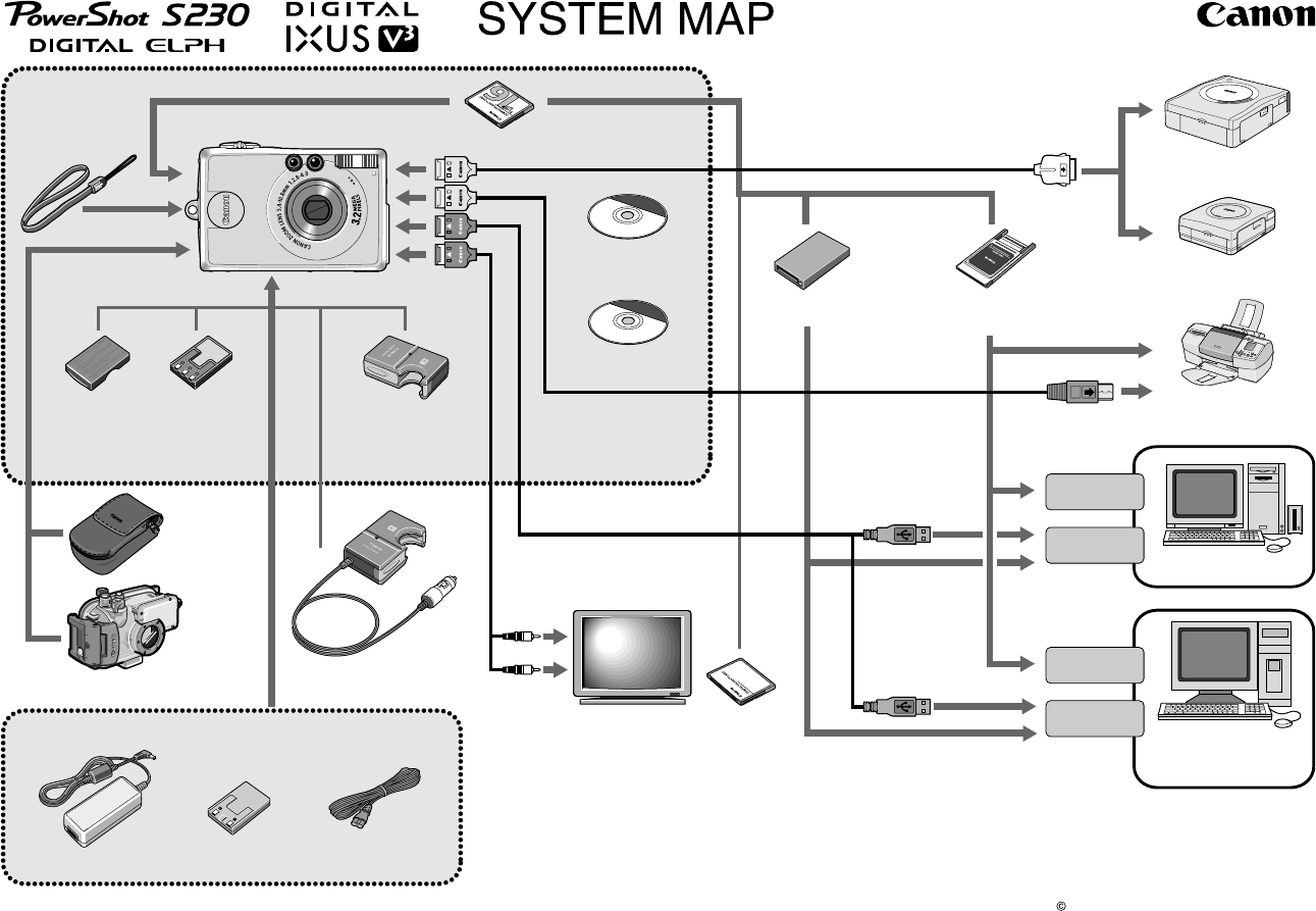
5-2 System diagram
2002 CANON INC. PRINTED IN JAPAN
CDI-E073-010 XXXXXXXXX
• (*1) Also available for purchase separately.
• (*2) Not sold in some regions.
• For more information, see the Quick Start Guide supplied with the Bubble Jet
Printer
For customers who have purchased the S820D BJ Printer: If two direct interfac
e
cables are not included with your printer, please contact your nearest support
center for BJ printers.
Supplied with Camera
Wrist Strap
WS-110
PowerShot S230 DIGITAL ELPH /
DIGITAL IXUS v
3
CF Card FC-16M (*1)
Canon Digital Camera
Solution Disk
ArcSoft Camera
Suite Disk
USB Interface Cable
IFC-200PCU (*1)
AV Cable
AVC-DC200 (*1)
Cover for
Battery Pack
Battery Charger
CB-2LS / 2LSE (*1)
Soft Case
SC-PS300 (*2)
Waterproof Case
WP-DC600
AC Adapter Kit ACK500
Compact Power Adapter
CA-PS500
AC Cable
DC Coupler
DR-500
Direct Interface Cable DIF-200(*1)
(Supplied with Card Photo Printer CP-100 / CP-10)
Card Photo Printer
CP-10
CF Card Reader PCMCIA Adapter
(PC Card Adapter) (*2 )
Card Photo Printer
CP-100
Direct Interface Cable
(Please refer to your
Bubble Jet Printer
Quick Start Guide for
cable information)
Bubble Jet Printer
(Compatible with the
direct print function)
USB Port
USB Port
PC Card Slot
PC Card Slot
IBM PC/AT
Compatible
Computer
Macintosh
Computer
TV / Video CF Card (*2)
• FC-16M
• FC-32M
• FC-64M
• FC-128M
• FC-256MH
Audio / V ideo
in Terminal
Car Battery Charger
CBC-NB1
Battery Pack
NB-1LH (*1)
1-36
γγ
γγ
γ
White balance 1
Exposure Memorized color
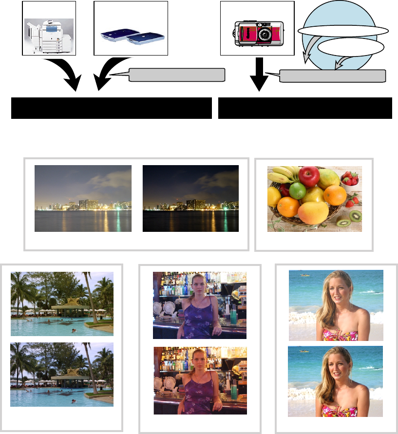
Fig.A-1 Comparison with image reproduction among copier,scanner and digital camera
Photo A-1 Picture comparison among decisive factors for image
White balance 2
6 Additional Guidance
6–1 iSAP (intelligent Scene Analysis based on Photographic Space) Technology
An important role of copiers and scanners is to faithfully reproduce the image quality of the original. With digital
cameras, on the other hand, it is essential to regenerate captured images naturally.
However, attempting to faithfully reproduce a captured image does not always result in a natural image. This is
why image rendering, an inherent technology of digital cameras, is so important to digital photography.
Image rendering is the inclusion of several elements including ‘exposure control appropriate to the scene =>
auto exposure (AE)’, ‘color reproduction based on human sense Æ addition of memorized colors’, ‘faithful
color reproduction independent of background colors/color reproduction that compensates for the color
temperature of the light source Æ auto white balance (AWB)’ and ‘tone representation that looks natural to the
eye Æ γ γ
γ γ
γ characteristic’. Obviously, image rendering assumes that ‘precise focus control Æ auto focus (AF)’
is performed as well.
Digital camera
Image Rendering Technology
AE , AW B, γ
Copier Scanner
Color Matching Technology
Faithful reproduction of original image quality Desirble image quality for photographer
VS
iSAP
Technology
Know-how from Film camera
Know-how from
Video camera

1-37
Fig. A-3 Flow of iSAPS technology
For more than 60 years since its inception, Canon has been asking ‘how can we take better pictures?’ As it has
progressed, Canon has built up a tremendous database of know-how on photography as a result of its camera
developments. From this photo data covering an enormous number of frames, Canon has classified statistically
the frequency that users take certain photos and created a ‘Photographic Space’ (Figure A-2) that relates the
‘peripheral brightness’ and the ‘distance between camera and subject’ according to the focal length (zoom
position) of the lens when taking a picture.
The PowerShot G3, the PowerShot S45 and the IXY
DIGITAL 320 all come with functions that utilize this
‘Photographic Space’ data.
Specifically, as shown in Figure A-3, the
distancebetween the camera and the subject is
estimated from the focal length (zoom position) of the
lens and the peripheral brightness when taking a
photo.
Furthermore, by adding ‘photo parameters’ which is
obtained with just before shooting, the scene that the
user is about to photograph is pre-analyzed and
precalculated. This method realizes faster and more
precise AF, AE and AWB than ever before.
• iSAPS High-speed AF
Using this iSAPS technology, the cameras achieve faster
focusing speeds by optimizing the control of the AF scan
range through a pre-analysis process to match the scene the
user is about to take.
• iSAPS Intelligent AE/AWB
Using this iSAPS technology, the cameras achieve precise exposure and white balance through an algorithm
optimized for the scene the user is about to take by analyzing the scene beforehand.
Fig.A-2 Distribution of object position
at specific focal-length
* Shortend form of ‘Photographic Space’
High speed and high precision AF, AE and AWB
Prediction of object position
from PS
*
information
Focusing from the most
promising focus-zone
Control by optimized algorithm
according to shooting conditions
AF
Lens focal length (Zoom position) ?
Reference of just before shooting
Brightness of object and environment ?
Low light ? Back light ?
Flash ON ?
AE
AWB
Infinity
Distance
Macro
Dark
Bright
Brigtness
Shooting Frequency
High
Row
Land-
scape
Outdoor portrait
Indoor snap


1. Functions of each unit
1.1 MAIN PCB ASS’Y --------------------------------------------------------------------------------------------------------- 2-1
1.2 FLASH/DC UNIT ----------------------------------------------------------------------------------------------------------- 2-1
2. Outline of Circuits
2.1 Power Supply Control ------------------------------------------------------------------------------------------------------ 2-2
2.1.1 Power Supply Block Diagram ----------------------------------------------------------------------------------- 2-2
2.1.2 Power Control Sequence ------------------------------------------------------------------------------------------ 2-2
2.2 Signal Processing ------------------------------------------------------------------------------------------------------------ 2-3
2.2.1 System Control ----------------------------------------------------------------------------------------------------- 2-3
2.2.2 Picture Processing ------------------------------------------------------------------------------------------------- 2-4
2.2.3 Audio Processing (During record and playback) -------------------------------------------------------------- 2-4
3. Troubleshooting
3.1 When an Error Code is Displayed ---------------------------------------------------------------------------------------- 2-5
3.2 When a Problem Occurs ---------------------------------------------------------------------------------------------------- 2-7
CHAPTER 2. TECHNICAL DESCRIPTION
CONTENTS

2-1
CHAPTER 2. TECHNICAL DESCRIPTION
1. Functions of each unit
1.1 MAIN PCB ASS’Y
1) Driving the CCD Sensor.
2) Conversion of the image signal from the analog signal to the digital signal.
3) Controlling the power supply and the system by CPU. (Refer to Sections 2.1 and 2.2.)
4) Image processing, and reading and writing the image signal to and from the CF card using DSP.
(Refer to Section 2.2.2.)
5) LCD drive and amplification of the video and audio output. (Refer to Section 2.2.3.)
1.2 FLASH/DC UNIT
1) Power supply drive (DC/DC converter).
2) Backlight for LCD drive.
3) Flash drive and charging circuit for the flash.
Fig. 1
MAIN PCB ASS’Y
FLASH/DC UNIT
2-2
CHAPTER 2. TECHNICAL DESCRIPTION
2. Outline of Circuits
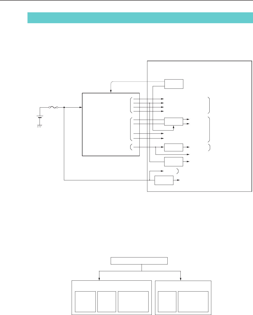
2.1 Power Supply Control
The power supply is controlled by the CPU mounted on the MAIN PCB ASS’Y.
2.1.1 Power Supply Block Diagram
Fig. 2 Power System Block Diagram
BATTERY
DC/DC
CONVERTER
CPU
Reg
Reg
Reg
VBATT
FUSE
OUTPUT
1, 2
VDD2
VDD3 (12V)
(13.5V) LCD Back Light
VEE2
OUTPUT 3
OUTPUT 4
(3.3V) for RTC
Reg
for System Control
for Image
Process
(CCD etc.)
for LCD
E1, E2, E3
E21
MAIN PCB ASS'Y
VCC1 (3.3V)
VCC1A (3.3V)
VCC1SD (3.3V)
VCC2RE (4.2 V)
VCC2AFE (3.3V)
VDD (15V)
VL (-7.5V)
VBATT for Motor Drive
VCC1A-3 (3.0V) for VIDEO OUT,
AUDIO OUT, LCD
2.1.2 Power Control Sequence
Main Switch ON (E1)
Shooting Mode Playback Mode
LCD OFF
(E2)
LCD ON
(E2, E3)
Audio/Video
out (E2)
LCD ON
(E3)
Audio/Video
out
2-3
CHAPTER 2. TECHNICAL DESCRIPTION
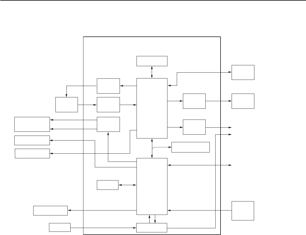
2.2 Signal Processing
Fig. 3 Signal System Block Diagram
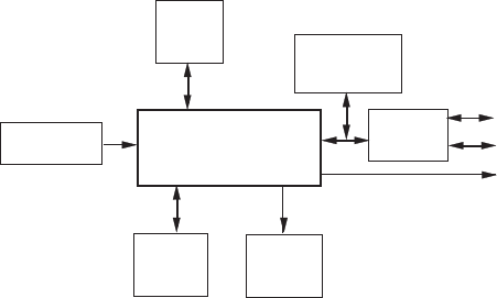
2.2.1 System Control
The CPU on the main PCB ass’y controls the EF lens (motor, shutter), operation switch receiver, USB
communication and flowing circuits.
•TG: Creation of the CCD drive pulse
•CDS, A/D: CCD signal processing and conversion of the digital data
•LCD Driver: Driving the LCD
•FLASH MEMORY: Firmware memory
•DSP: Picture processing
•RTC: Clock count for watch
•AF Support LED: AF auxiliary, self-timer and red-eye protection also serves as a lamp
•Electric Flash: Flash and charging circuit
CDS, A/D
LCD
Driver
CCD
Sensor
TG
Drive
Pulse
HD, VD
CLK
EF LENS Motor
Driver
AF Support LED
FINDER LED
Electric FLASH
CF card
LCD
Video
Amp
RTC
MIC
FLASH MEMORY
AUDIO AMP
DSP
CPU
SW
DIAL
KEY
MAIN PCB ASS'Y
SDRAM
USB
VIDEO OUT
AUDIO OUT

2-4
CHAPTER 2. TECHNICAL DESCRIPTION
2.2.2 Picture Processing
1) The drive pulse of the CCD sensor is created by both clock from DSP and TG that is operated by
sync. signal.
The picture signal by the drive pulse is output from CCD sensor.
The output signal of the CCD picture is converted to the signal processing and the digital data by
the CDS and A/D converter, and is sent to the DSP.
2) The DSP circuit performs the following signal processing.
•Processes the picture data (using the SDRAM).
•Writes and reads the picture data to and from the CF card.
•Outputs analog video signal to the LCD and VIDEO OUT.
3) The video signal that is supplied form the DSP is controlled by the LCD driver and is displayed
on the LCD.
4) The video amplifier is activated when the video plug is inserted to the AV connector and drives
the video signal in 75 Ω.
2.2.3 Audio Processing (During record and playback)
1) During animation recording.
•The microphone audio signal is converted to the digital data by CPU and is recorded.
2) During playback, the data is converted back to the analog audio signal and is output to the AV
connector.

2-5
CHAPTER 2. TECHNICAL DESCRIPTION
Error Code
E02
E03
E09
E14
E16
E18
E23
E24
E25
E26
Name
AF
TIME OUT
EF
TIME OUT
JPEG DMA
TIME OUT
UNKOWN
IMAGING TIME
OUT
ZOOM LENS
ERROR
CF NO SPACE
POWER ON
ERROR
FOCUS PI
ERROR
CAPTURE
TIME OUT
Occurrence Conditions
AF processing did not end within the
specified time.
The focus lens was not driven.
Auto Flash Control did not end within the
specified time.
JPEG processing did not end within the
specified time.
When unkown error, cause of which is
not known, occurs.
When communication between CPU and
peripheral IC is not completed within the
specified time during recording using
EVF or after completion of recording.
Movement of the lens barrel did not end
within the specified time.
When the CF becomes full during writing
of photographed images to CF, writing is
repeatedly performed with the JPEG
compression ratio successively increased
to reduce the size of the image file until it
can be successfully written to CF.
This error occurs when writing of the
JPEG image file fails after 10 retries at
increasingly higher compression ratios.
The power of the imaging circuit on the
MAIN PCB ASS’Y was not detected.
Detection of the focus PI (photo-
interrupter) failed.
Writing of the photograph image to
SDRAM did not end within the specified
time.
Cause and Probable Faulty Part
MAIN PCB ASS’Y
MAIN PCB ASS’Y
MAIN PCB ASS’Y
MAIN PCB ASS’Y
UNKOWN
MAIN PCB ASS’Y
MAIN PCB ASS’Y
MAIN PCB ASS’Y
MAIN PCB ASS’Y
OPTICAL UNIT
MAIN PCB ASS’Y
MAIN PCB ASS’Y
3. Troubleshooting
3.1 When an Error Code is Displayed
[Remedy]
•Check for any abnormalities in the mounting of probable faulty parts or connector connections referring
to the table below.
•Try replacing probable faulty parts referring to the below.
[NOTE]
•The error code is displayed on the LCD Monitor.
•Adjustments must be performed after the part has been replaced. For details, see the chapter of
“Adjustments”.

2-6
CHAPTER 2. TECHNICAL DESCRIPTION
Error Code
E27
E30
E50
E51
E52
Name
CF WRITE
TIME OVER
POWER OFF
ERROR
CF FORMAT
ERROR
CF ACCESS
ERROR
QUICK REVIEW
ERROR
Occurrence Conditions
Free area could not be secured in the
buffer for the photograph image within
the specified time in the continuous
shooting mode.
The camera power was turned OFF while
the image was being recorded to the CF
Card. (The error code is displayed when
the camera is next turned ON.)
* This error may occur after E23.
The CF Card could not be formatted
properly.
When image data cannot be read from
CF normally.
Review of the photograph image failed.
Cause and Probable Faulty Part
CF CARD
MAIN PCB ASS’Y
The battery or DC plug was removed
while the image was being recorded to
the CF Card.
→ Remedy: Restart the camera.
CF CARD
CF CARD
MAIN PCB ASS’Y

2-7
CHAPTER 2. TECHNICAL DESCRIPTION
3.2 When a Problem Occurs
[Remedy]
•Check for any abnormalities in the mounting of probable faulty parts or connector connections referring
to the table below.
•Try replacing probable faulty parts referring to the table below.
[NOTE]
•Adjustments must be performed after the part has been replaced. For details, see the chapter of
“Adjustments”.
Cause and Probable Faulty Part
MAIN PCB ASS’Y
REAR COVER UNIT
FLASH/DC UNIT
BATTERY BOX UNIT
MAIN PCB ASS’Y
BUTTON PCB ASS’Y
LCD PANEL
BACK LIGHT UNIT
OPTICAL UNIT
MAIN PCB ASS’Y
OPTICAL UNIT
MAIN PCB ASS’Y
BATTERY BOX UNIT
REAR COVER UNIT
FLASH/DC UNIT
MAIN PCB ASS’Y
MAIN PCB ASS’Y
CF CARD
REAR COVER UNIT
MAIN PCB ASS’Y
REAR COVER UNIT
RLS PCB ASS’Y
Problem (when an error code is not displayed)
The camera does not work.
The image is not displayed on the LCD Monitor.
The photograph image is abnormal.
The zoom does not function.
The Built-in Flash does not fire.
Video output is strange.
Communications with the personal computer is not possible.
The CF card or Micro Drives is not recognized.
Buttons/The Mode dial do not work.


CHAPTER 3. REPAIR INSTRUCTION
CONTENTS
1. Before Starting the Repair Work ------------------------------------------------------------------------------------------------ 3-1
1.1 Precaution on Flash High Tension Circuit ------------------------------------------------------------------------------- 3-1
1.2 List of Supplies -------------------------------------------------------------------------------------------------------------- 3-1
1.3 Flexible Connectors --------------------------------------------------------------------------------------------------------- 3-2
2. Disassembly/Assembly ----------------------------------------------------------------------------------------------------------- 3-3
2.1 Procedure --------------------------------------------------------------------------------------------------------------------- 3-3
2.2 REAR COVER UNIT, CF COVER -------------------------------------------------------------------------------------- 3-4
2.3 FRONT COVER UNIT ---------------------------------------------------------------------------------------------------- 3-5
2.4 SHUTTER BUTTON UNIT ----------------------------------------------------------------------------------------------- 3-6
2.5 SHIELD SHEET, MAIN PCB ASS’Y ----------------------------------------------------------------------------------- 3-7
2.6 LITHIUM BATTERY (2ND), MICROPHONE UNIT ---------------------------------------------------------------- 3-8
2.7 BATTERY LOCK, BATTERY COVER -------------------------------------------------------------------------------- 3-9
2.8 OPERATION KEY UNIT, TRIPOD SOCKET ---------------------------------------------------------------------- 3-10
2.9 LCD PANEL, BACK LIGHT UNIT ------------------------------------------------------------------------------------3-11
2.10 OPERATION PLATE, BATTERY BOX UNIT, CF UNIT ---------------------------------------------------------3-12
2.11 OPTICAL UNIT, FINDER UNIT --------------------------------------------------------------------------------------3-13
2.12 Assembling the FINDER UNIT ---------------------------------------------------------------------------------------- 3-14
2.13 OPTICAL UNIT ---------------------------------------------------------------------------------------------------------- 3-15
2.14 FLASH/DC UNIT, FLASH UNIT, ELECT CAPACITOR ---------------------------------------------------------3-16
2.15 Screw List ----------------------------------------------------------------------------------------------------------------- 3-17
3. Adjustments -----------------------------------------------------------------------------------------------------------------------3-18
3.1 Replacement Parts and Adjustment Items ----------------------------------------------------------------------------- 3-18
3.2 Adjustment Tools ----------------------------------------------------------------------------------------------------------3-19
3.3 Before Starting Electrical Adjustments ---------------------------------------------------------------------------------3-20
3.3.1 TWAIN Driver Installation --------------------------------------------------------------------------------------3-20
3.3.2 Installing the Adjustment Software --------------------------------------------------------------------------- 3-20
3.3.3 Preparation -------------------------------------------------------------------------------------------------------- 3-22
3.3.4 Starting up the Adjustment Software ---------------------------------------------------------------------------3-23
3.3.5 Menu Window-----------------------------------------------------------------------------------------------------3-23
3.3.6 How to Use the Adjustment Software -------------------------------------------------------------------------3-23
3.4 Calibration ----------------------------------------------------------------------------------------------------------------- 3-24
3.4.1 Calibration -------------------------------------------------------------------------------------------------------- 3-24
3.5 Adjustment Procedure -----------------------------------------------------------------------------------------------------3-29
3.5.1 CCD Adjustment ------------------------------------------------------------------------------------------------- 3-29
3.5.2 Optical Unit Adjustment ---------------------------------------------------------------------------------------- 3-31
3.5.3 Imaging Process Adjustment ------------------------------------------------------------------------------------3-33
3.5.4 Color Adjustment -------------------------------------------------------------------------------------------------3-36
3.5.5 Pixel Dot Adjustment --------------------------------------------------------------------------------------------3-38
3.5.6 Flash Adjustment -------------------------------------------------------------------------------------------------3-40
3.5.7 Checking of sound recording/output ---------------------------------------------------------------------------3-42

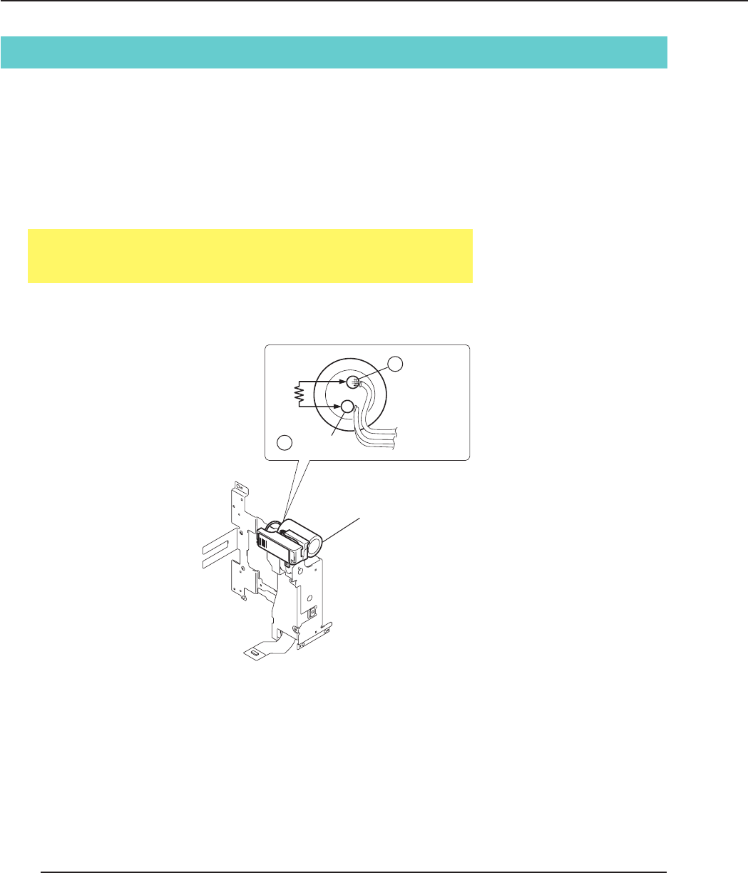
3-1
CHAPTER 3. REPAIR INSTRUCTION
Fig. 3-1 Precaution on flash high tension circuit
1. Before Starting the Repair Work
Be sure to read the following precaution before starting the repair work.
1.1 Precaution on Flash High Tension Circuit
• When the OPTICAL UNIT is removed, be sure to discharge the main capacitor.
(Discharging resistor: 1 k ohms, approx. 5 W.)
• First contact the GND (–) terminal of the main capacitor with the discharging resistor. Then contact the
positive (+) terminal of the main capacitor.
CAUTION:
Be careful of electric shock because the circuit is the high tension circuit.
1.2 List of Supplies
The following supplies are used for the re-assembling during service.
(1) List of supplies
New Name of supplies Part No. Areas where supplies are used
DIA BOND 1663G CY9-8129-000 Attaching the parts together
ADHESIVE TAPE, SONY T4000 CY4-6012-000 Fixing the flexible cable
ADHESIVE TAPE, 3M NO.56 CY4-6018-000 BATTERY BOX UNIT
HANARL (OIL) DY9-3026-010 OPTICAL UNIT
FLASH UNIT
+ terminal
– terminal

3-2
CHAPTER 3. REPAIR INSTRUCTION
CAUTIONS:
1. For the connectors of Type C and Type D, set them to the unlocked
state before removing and inserting flexible card. After flexible card
is inserted, set them to the locked state.
2. The flexible card is equipped with the holes as shown. Use them for
removal and insertion by inserting the tweezers into them as required.
1.3 Flexible Connectors
This product uses the four types of the flexible connectors.
Fig. 3-3 Holes for removal
Fig. 3-2 Flexible connectors
The contact-piece
should face
upwards
4 Type D
3 Type C
Unconnected state Connected state
Unconnected state Connected state
Unlocked state Locked state
Unlocked state Locked state
Holes
1 Type A
2 Type B
LOCK
UNLOCK
UNLOCK LOCK
The contact-piece
should face
downwards
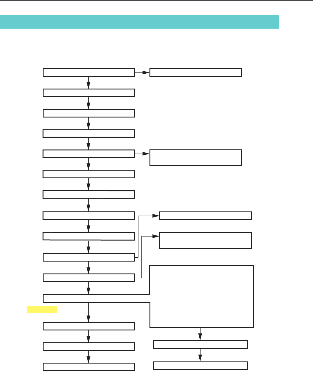
3-3
CHAPTER 3. REPAIR INSTRUCTION
2. Disassembly/Assembly
2.1 Procedure
Disassembling procedure of PowerShot S230 and DIGITAL IXUS v3 is shown by the following flowchart.
Reverse the disassembling procedure to reassemble them. ∗ The pages to refer are shown in parenthesis ( ).
Be careful high tension
CAUTION
Assembling the FINDER UNIT (3-14)
SHIELD SHEET (3-7)
SHUTTER BUTTON UNIT (3-6)
CF COVER (3-4)
LITHIUM BATTERY (2ND) (3-8)
MICROPHONE UNIT (3-8)
REAR COVER UNIT (3-4)
FRONT COVER UNIT (3-5)
BATTERY LOCK (3-9)
MAIN PCB ASS'Y (3-7)
BATTERY COVER (3-9)
OPERATION KEY UNIT (3-10)
TRIPOD SOCKET (3-10)
FINDER UNIT (3-13)
FLASH/DC UNIT (3-16)
FLASH UNIT (3-16)
ELECT CAPACITOR (3-16)
OPTICAL UNIT (3-13)
BACK LIGHT UNIT (3-11)
LCD PANEL (3-11)
BATTERY BOX UNIT (3-12)
CF UNIT (3-12)
OPERATION PLATE (3-12)
BARREL1 CAP (3-15)
FRONT CAP (3-15)
BARRIER PLATE (3-15)
BARRIER BASE (3-15)
BARRIER DRIVE PLATE (3-15)
BARRIER CLOSE SPRING (3-15)
BARRIER OPEN SPRING (3-15)
BARRIER DRIVE RING (3-15)
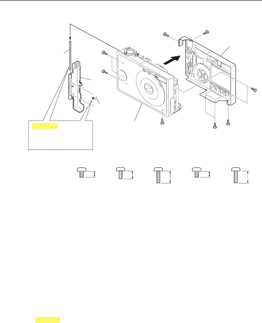
3-4
CHAPTER 3. REPAIR INSTRUCTION
Fig. 3-4 REAR COVER UNIT, CF COVER
(1)-1 a
(1)-1
b
(1)-1
REAR COVER UNIT
(1)-2
b
(1)-1
e
(1)-1
c
(1)-1
(1)-1
d
d
(1)-1
a
FRONT COVER UNIT
CF COVER
SHAFT
(2)-2
CF COVER
(2)-1
CF COVER
SPRING
(2)-3
2.0mm
METAL
M1.7
CD1-3109-000
a
3.5mm
METAL
M1.7
CD1-3110-000
c
2.8mm
METAL
M1.7
(SELF TAP)
CD1-3112-000
b
2.5mm
METAL
M1.7
CD1-4248-000
d
3.5mm
METAL
M1.7
(SELF TAP)
CD1-4183-000
e
Be careful not to drop the
CF COVER SHAFT and
CF COVER SPRING.
CAUTION
2.2 REAR COVER UNIT, CF COVER
(1) REAR COVER UNIT
1. Remove the four screws of a and the two screws of b and the two screws of c and the two screws of d
and the screw of e.
2. Remove the REAR COVER UNIT in the direction of arrow.
(2) CF COVER
1. Remove the CF COVER.
2. Remove the CF COVER SHAFT.
3. Remove the CF COVER SPRING.
CAUTION
Be careful not to drop the CF COVER SHAFT and CF COVER SPRING.
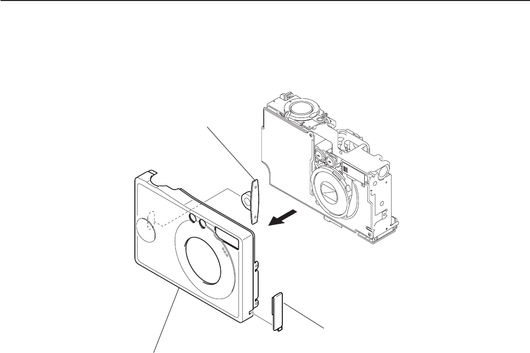
3-5
CHAPTER 3. REPAIR INSTRUCTION
Fig. 3-5 FRONT COVER UNIT
STRAP RING
(1)-3
JACK COVER
(1)-2
(1)-1
FRONT COVER UNIT
2.3 FRONT COVER UNIT
(1) FRONT COVER UNIT
1. Remove the FRONT COVER UNIT in the direction of arrow.
2. Remove the JACK COVER.
3. Remove the STRAP RING.
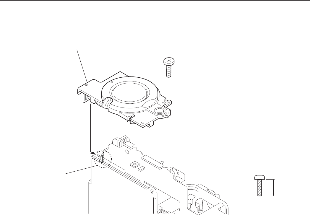
3-6
CHAPTER 3. REPAIR INSTRUCTION
Fig. 3-6 SHUTTER BUTTON UNIT
2.4 SHUTTER BUTTON UNIT
(1) SHUTTER BUTTON UNIT
1. Remove the screw of f.
2. While taking care of the claw remove the SHUTTER BUTTON UNIT.
Claw
(1)-1
f
(1)-2
SHUTTER BUTTON UNIT
4.0mm
BLACK
M1.7
(SELF TAP)
XA4-9170-409
f
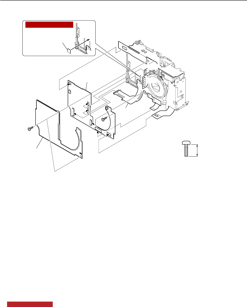
3-7
CHAPTER 3. REPAIR INSTRUCTION
Fig. 3-7 SHIELD SHEET, MAIN PCB ASS’Y
2.5 SHIELD SHEET, MAIN PCB ASS’Y
(1) SHIELD SHEET
1. Remove the two screws of g.
2. Remove the SHIELD SHEET.
(2) MAIN PCB ASS’Y
1. Remove the screw of g.
2. Remove the Connector of the BATTERY BOX UNIT.
3. Remove the Connector of the OPTICAL UNIT.
4. Remove the Connector of the CF UNIT.
5. Remove the flexible printed wired board of the OPTICAL UNIT.
6. Remove the flexible printed wired board of the OPERATION KEY UNIT.
7. Remove the flexible printed wired board of the LCD.
8. Remove the Connector of the FLASH/DC UNIT.
9. Remove the MAIN PCB ASS’Y.
NOTE (Assembling)
Attach the Double-sided adhesive tape to the BATTERY BOX UNIT.
(2)-2
(1)-1
g(2)-1
g
SHIELD SHEET
(1)-2
MAIN PCB ASS'Y
(2)-9
(2)-5
(2)-6
(2)-7
(2)-8
(2)-3
(2)-4
Double-sided
adhesive tape
NOTE (Assembling)
3.5mm
METAL
M1.7
XA1-7170-357
g
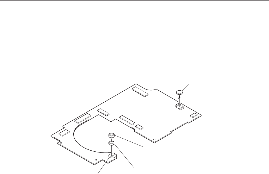
3-8
CHAPTER 3. REPAIR INSTRUCTION
Fig. 3-8 LITHIUM BATTERY (2ND), MICROPHONE UNIT
2.6 LITHIUM BATTERY (2ND), MICROPHONE UNIT
(1) LITHIUM BATTERY (2ND)
1. Remove the LITHIUM BATTERY. (2ND)
(2) MICROPHONE UNIT
1. Remove the MICROPHONE HOLDER.
2. Remove soldering. (Two places)
3. Remove the MICROPHONE UNIT.
Remove soldering
LITHIUM BATTERY (2ND)
(1)-1
(2)-2
MICROPHONE HOLDER
(2)-1
MICROPHONE UNIT
(2)-3
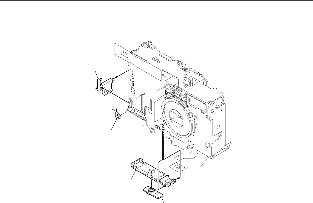
3-9
CHAPTER 3. REPAIR INSTRUCTION
Fig. 3-9 BATTERY LOCK, BATTERY COVER
2.7 BATTERY LOCK, BATTERY COVER
(1) BATTERY LOCK
1. Remove the BATTERY LOCK SPRING.
2. Remove the BATTERY LOCK.
(2) BATTERY COVER
1. Remove the BATTERY COVER.
2. Remove the DC COUPLER COVER.
BATTERY LOCK
(1)-2
BATTERY LOCK SPRING
(1)-1
BATTERY COVER
(2)-1
DC COUPLER COVER
(2)-2
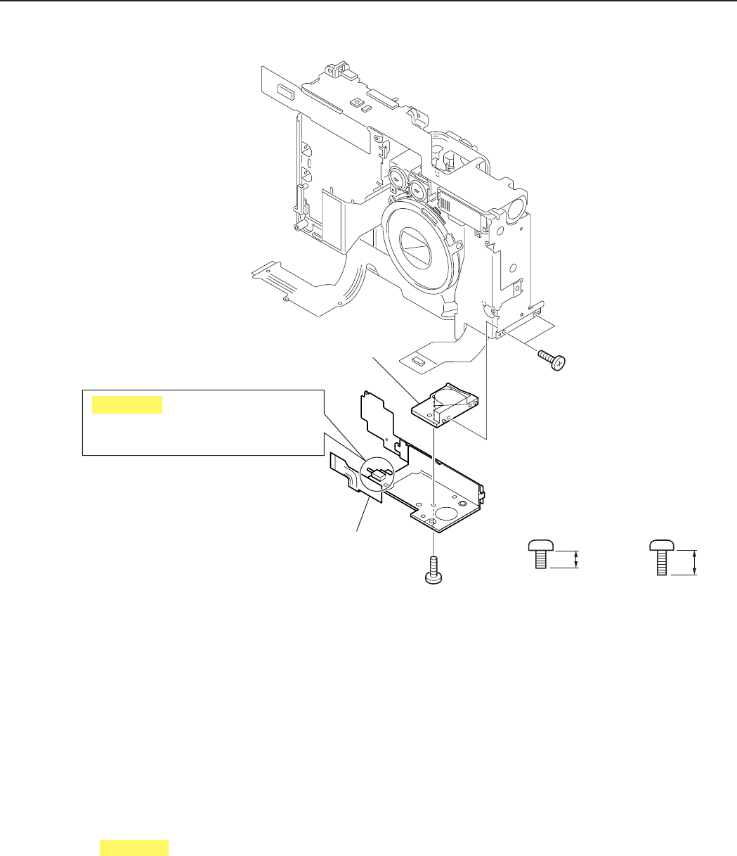
3-10
CHAPTER 3. REPAIR INSTRUCTION
Fig. 3-10 OPERATION KEY UNIT, TRIPOD SOCKET
2.8 OPERATION KEY UNIT, TRIPOD SOCKET
(1) OPERATION KEY UNIT
1. Remove the screw of h.
2. Remove the OPERATION KEY UNIT.
CAUTION
Be careful not to break the detection switch of the BATTERY COVER.
(2) TRIPOD SOCKET
1. Remove the two screws of i.
2. Remove the TRIPOD SOCKET
TRIPOD SOCKET
(2)-2
OPERATION KEY UNIT
(1)-2
(2)-1
i
(1)-1
h
2.0mm
METAL
M1.7
CD1-3108-000
h
3.0mm
METAL
M1.7
XA1-7170-307
i
Be careful not to break the detection
switch of the BATTERY COVER.
CAUTION
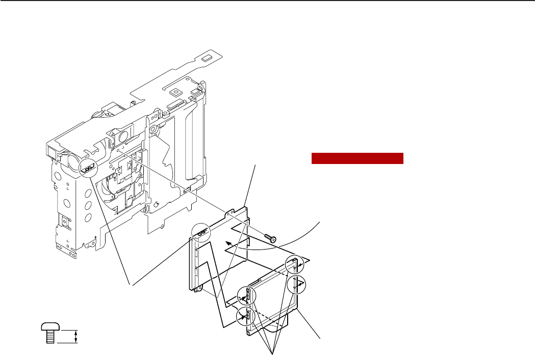
3-11
CHAPTER 3. REPAIR INSTRUCTION
Fig. 3-11 LCD PANEL, BACKLIGHT UNIT
(1)-2
h
BACK LIGHT UNIT
(1)-3
LCD PANEL
Claws
(1)-1
The BACKLIGHT UNIT that is
supplied as the service part has
the protection sheet on the back.
Remove it.
NOTE (Assembling)
(1)-3
Remove soldering
2.0mm
METAL
M1.7
CD1-3108-000
h
2.9 LCD PANEL, BACK LIGHT UNIT
(1) LCD PANEL, BACK LIGHT UNIT
1. While taking care of the claws remove the LCD PANEL.
2. Remove the two screws of h.
3. Remove soldering (Two places) and remove the BACK LIGHT UNIT.
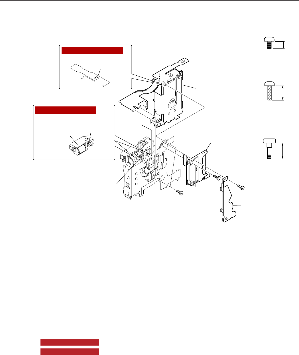
3-12
CHAPTER 3. REPAIR INSTRUCTION
Fig. 3-12 OPERATION PLATE, BATTERY BOX UNIT, CF UNIT
Remove soldering (1)-1
h
(2)-1
j
CF UNIT
(3)-1
OPERATION PLATE
(1)-2
BATTERY BOX UNIT
(2)-3
(2)-2
Insulation tape
DIABOND
(1633G)
Double-sided
adhesive tape
NOTE2 (Assembling)
NOTE1 (Assembling)
(3)-1
k
2.0mm
METAL
M1.7
CD1-3108-000
h
3.5mm
BLACK
M1.7
(SELF TAP)
XA4-9170-359
j
3.8mm
METAL
M2.0
CD1-3105-000
k
2.10 OPERATION PLATE, BATTERY BOX UNIT, CF UNIT
(1) OPERATION PLATE
1. Remove the screw of h.
2. Remove the OPERATION PLATE.
(2) BATTERY BOX UNIT
1. Remove the two screws of j.
2. Remove soldering. (Two places)
3. Remove the BATTERY BOX UNIT.
NOTE1 (Assembling)
Attach the Double-sided adhesive tape to the BATTERY BOX UNIT flexible.
NOTE2 (Assembling)
Attach the DIABOND and Double-sided adhesive tape to the BATTERY BOX UNIT
flexible.
(3) CF UNIT
1. Remove the two screws of k.
2. Remove the CF UNIT.
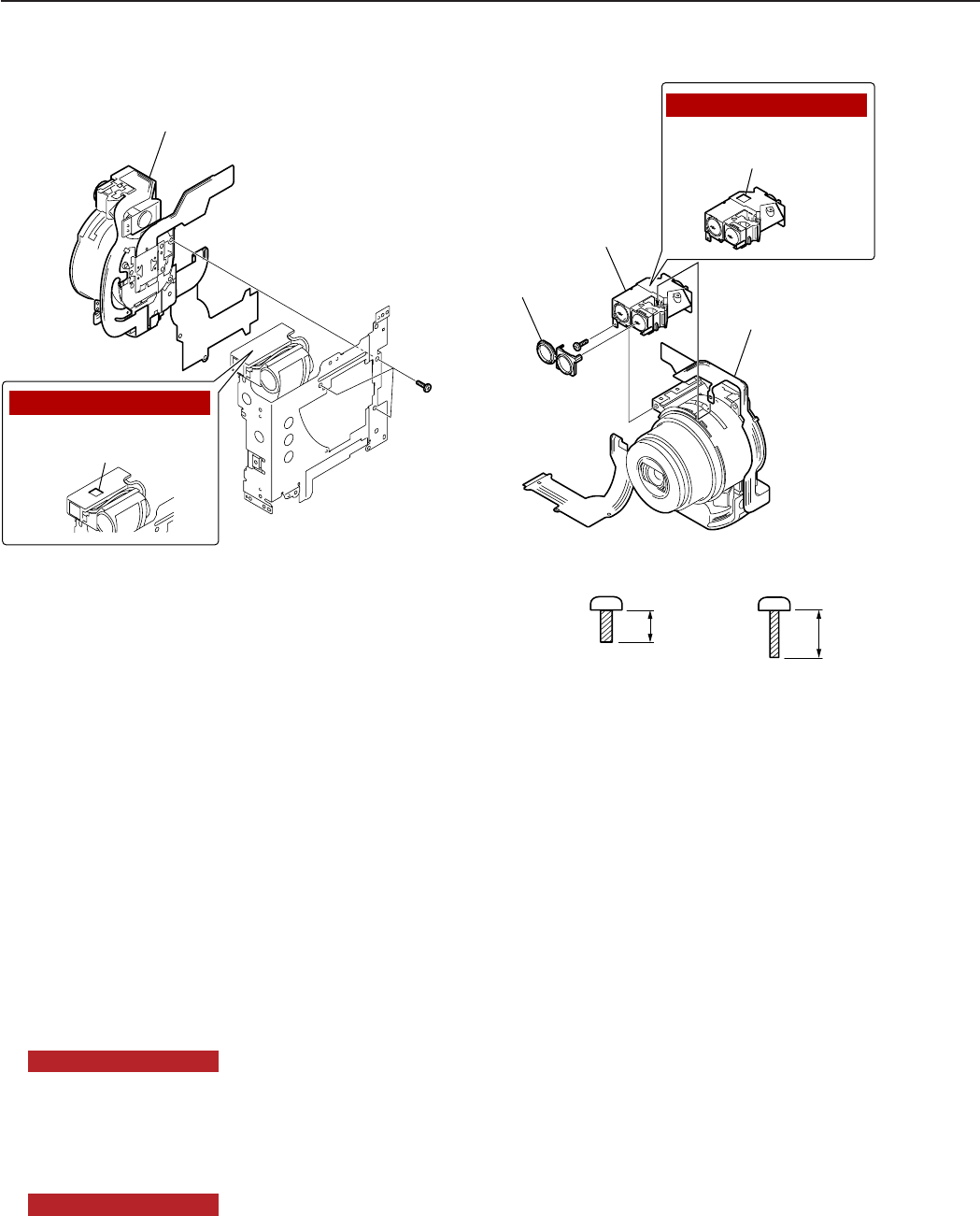
3-13
CHAPTER 3. REPAIR INSTRUCTION
Fig. 3-13 OPTICAL UNIT, FINDER UNIT
(1)-1
n
OPTICAL UNIT/FINDER UNIT
(1)-2
OPTICAL UNIT
(2)-3
(2)-3
FINDER UNIT
(2)-1
Double-sided
adhesive tape
Double-sided
adhesive tape
NOTE2 (Assembling)
NOTE1 (Assembling)
(2)-2
o
FINDER RUBBER
3.0mm
METAL
M1.4
(SELF TAP)
BLACK
M1.7
(SELF TAP)
XA4-5170-309
n
3.5mm
XA4-9140-357
o
2.11 OPTICAL UNIT, FINDER UNIT
(1) OPTICAL UNIT
1. Remove the three screws of n.
2. Remove the OPTICAL UNIT/FINDER UNIT.
NOTE1 (Assembling)
Attach the Double-sided adhesive tape to the FLASH UNIT.
(2) FINDER UNIT
1. Remove the FINDER RUBBER.
2. Remove the screw of o.
3. Remove the OPTICAL UNIT and FINDER UNIT.
NOTE2 (Assembling)
Attach the Double-sided adhesive tape to the FINDER UNIT.
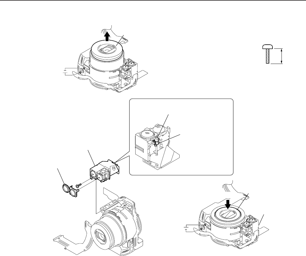
3-14
CHAPTER 3. REPAIR INSTRUCTION
Fig. 3-14 Assembling the FINDER UNIT
2.12 Assembling the FINDER UNIT
(1) Assembling the FINDER UNIT
1. Apply the voltage (DC 2.5V) across the motor terminal to drive the motor until the motor stops and the
BARREL fully comes out.
2. Move the SLIDER fully to the top of the BARREL and secure it with the screw of o.
3. Assembling the FINDER RUBBER to FINDER UNIT.
4. Apply the voltage (DC 2.5V) across the motor terminal to drive the motor until the motor stops and the
BARREL is full housed.
(1)-4
DC2.5V
(1)-1
(1)-2
(1)-2
(1)-2
(1)-4
FINDER UNIT
The SLIDER must have been moved
fully to the top of the BARREL.
BARREL
BARREL
SLIDER
FINDER UNIT
(1)-3
FINDER RUBBER
o
(1)-1
DC2.5V
METAL
M1.4
(SELF TAP)
3.5mm
XA4-9140-357
o
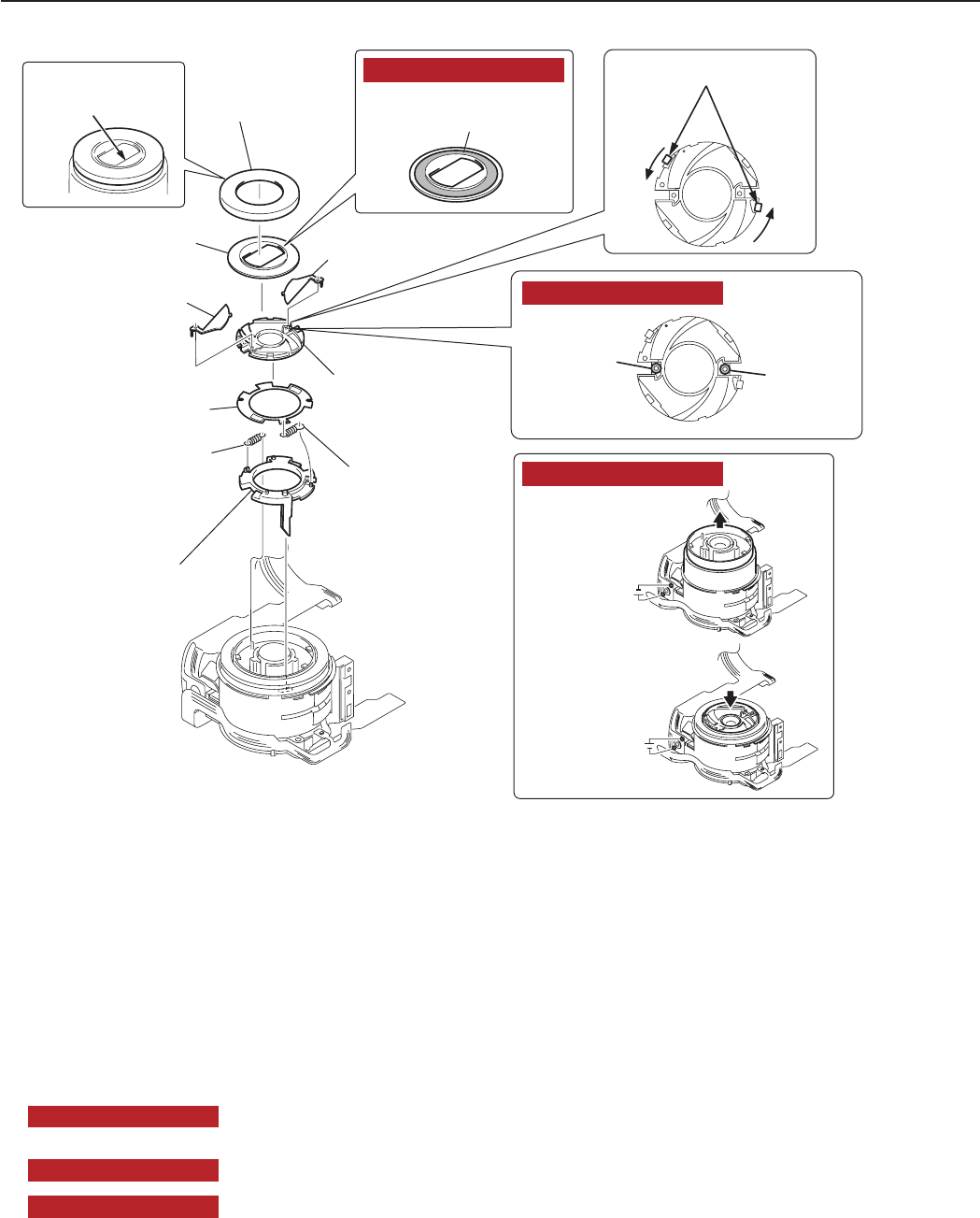
3-15
CHAPTER 3. REPAIR INSTRUCTION
Fig. 3-15 OPTICAL UNIT
2.13 OPTICAL UNIT
(1) OPTICAL UNIT
1. Remove the BARREL1 CAP by inserting tweezers or the like into its groove.
2. Remove the FRONT CAP.
3. Remove the BARRIER PLATE (2 pieces).
4. Remove the two claws and remove the BARRIER BASE.
5. Remove the BARRIER DRIVE PLATE.
6. Remove the BARRIER CLOSE SPRING.
7. Remove the BARRIER OPEN SPRING.
8. Remove the BARRIER DRIVE RING.
NOTE1 (Assembling)
Apply the voltage (DC 2.5V) across the motor terminal to drive the motor until the
motor stops and the BARREL is full housed.
NOTE2 (Assembling)
Attach the DIABOND to the FRONT CAP.
NOTE3 (Assembling)
Attach the HANARL to the BARRIER BASE.
BARREL1 CAP
BARRIER PLATE
BARRIER PLATE
BARRIER BASE
BARRIER DRIVE
PLATE
BARRIER DRIVE
RING
BARRIER
CLOSE SPRING
BARRIER OPEN
SPRING
FRONT CAP
(1)-4
(1)-3
(1)-2
(1)-3
(1)-4
(1)-5
(1)-6
(1)-7
(1)-8
(1)-1 (1)-1
DC2.5V
DC2.5V
Insert tweezers
or the like.
Remove the claws
HANARL
(OIL) HANARL
(OIL)
DIABOND
(1633G)
NOTE2 (Assembling)
NOTE3 (Assembling)
NOTE1 (Assembling)
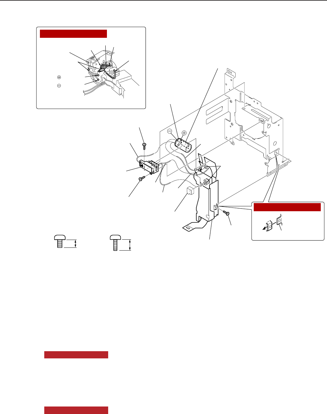
3-16
CHAPTER 3. REPAIR INSTRUCTION
Fig. 3-16 FLASH/DC UNIT, FLASH UNIT, ELECT CAPACITOR
2.14 FLASH/DC UNIT, FLASH UNIT, ELECT CAPACITOR
(1) FLASH/DC UNIT
1. Remove the screw of h and two screws of l.
2. Remove the FLASH/DC UNIT.
NOTE1 (Assembling)
Please insert the projection of MAIN FRAME in the slot of FLASH/DC UNIT.
(2) FLASH UNIT, ELECT CAPACITOR
1. Remove the TRIGGRE CAP
2. Remove soldering. (white, black, gray, orange, pink )
3. Remove the FLASH UNIT.
4. Remove the ELECT CAPACITOR.
NOTE2 (Assembling)
Attach the DIABOND.
Remove soldering
(2)-2
ELECT CAPACITOR
(2)-4
Remove
soldering
(2)-2
FLASH UNIT
(2)-3
TRIGGRE CAP
(2)-1
white gray
orange
black
pink
FLASH/DC UNIT
(1)-2
(1)-1
l
(1)-1
l
(1)-1
hProjection part
black gray
orange
white
terminal
DIABOND
(1633G)
terminal
NOTE1 (Assembling)
NOTE2 (Assembling)
2.0mm
METAL
M1.7
CD1-3108-000
h
3.0mm
METAL
M1.4
XA1-7140-307
l
Silicon

3-17
CHAPTER 3. REPAIR INSTRUCTION
2.15 Screw List
2.0mm
METAL
M1.7
CD1-3109-000
a
2.0mm
METAL
M1.7
CD1-3108-000
h
3.5mm
METAL
M1.7
CD1-3110-000
c
2.8mm
METAL
M1.7
(SELF TAP)
CD1-3112-000
b
3.5mm
METAL
M1.7
XA1-7170-357
g
4.0mm
BLACK
M1.7
(SELF TAP)
XA4-9170-409
f
3.5mm
3.0mm
METAL
M1.7
(SELF TAP)
CD1-4183-000
e
3.0mm
METAL
M1.7
XA1-7170-307
i
3.0mm
METAL
M1.4
XA1-7140-307
l
3.5mm
BLACK
M1.7
(SELF TAP)
XA4-9170-359
j
METAL
M1.4
(SELF TAP)
BLACK
M1.7
(SELF TAP)
XA4-5170-309
n
3.8mm
METAL
M2.0
CD1-3105-000
k
2.5mm
METAL
M1.7
CD1-4248-000
d
3.5mm
XA4-9140-357
o
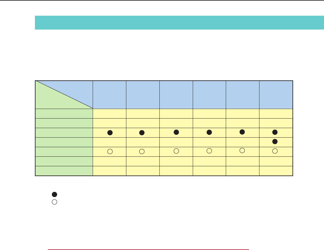
3-18
CHAPTER 3. REPAIR INSTRUCTION
3. Adjustments
3.1 Replacement Parts and Adjustment Items
PowerShot S230/DIGITAL IXUS v3 requires electrical adjustments when certain parts are replaced.
The table below indicates the adjustments required for the respective part replacements.
For all other parts not listed below, no electrical adjustments are necessary after replacement.
Adjustment Items
Replacement Part
BATTERY BOX UNIT
DC/DC CONV. UNIT
OPTICAL UNIT
FLASH UNIT
MAIN PCB ASS’Y
LCD PANEL
BACK LIGHT UNIT
CCD
Adjustment
#1
Optical Unit
Adjustment
#2
Imaging
Process
Adjustment
#3
Pixel Dot
Adjustment
#5
: Adjustment is necessary after replacement.
: Adjustment is necessary after replacement.
(Adjustment is not necessary, only if the adjustment data has been saved and then transferred
after the part is replaced.)
Blank : Adjustment is unnecessary.
∗ When OPTICAL UNIT is replaced, adjust certainly at the procedure as below.
#1. CCD Adjustment
#2. Optical Unit Adjustment
#3. Imaging Process Adjustment
#4. Color Adjustment
#5. Pixel Dot Adjustment
#6. Flash Adjustment
Flash
Adjustment
#6
Color
Adjustment
#4

3-19
CHAPTER 3. REPAIR INSTRUCTION
3.2 Adjustment Tools
The following tools are required for electrical adjustment.
*1 Print the Zoom/AF Chart on the legal size paper from the “Zoom_AFChart_Legal.pdf ” ( in the folder of
this CD-ROM, :\Adjust\Chart).
Print the Auto Focus Chart on the A3 size paper from the “Zoom_AFChart_A3.pdf ”.
*2 2pcs. required.
DESCRIPTION
PC/AT-Compatible Machine
(Windows98 or 2000 pre-installed Model, USB port)
Adjustment Software (CD-ROM)
Compact Power Adapter CA-PS500
AC Cable
DC Coupler DR-500
INTERFACE CABLE IFC-200PCU
Brightness Box (light source A)
Color Viewer (5600° K)
Color Bar Chart
18% Gray Chart
Zoom/AF Chart
W-10 Filter *2
C-12 Filter
FL-W Filter
ND-2 Filter
ND-4 Filter
ND-8 Filter
Light-Shielding Cloth (500 × 500 or larger)
Tripod
Reference Camera
DIGITAL CAMERA SolutionDisk Ver.11
PARTS NO.
—
CY8-4380-031
—
—
—
—
—
DY9-2039-100
DY9-2002-000
CY4-6016-000
—
CY9-1543-000
DY9-2029-000
CY9-1550-000
—
—
—
—
—
—
—
REMARKS
Local purchase
CD-ROM,
SERVICE MANUAL (J/E)
Enclosed in
“AC Adapter Kit ACK500”
Enclosed in
“AC Adapter Kit ACK500”
Enclosed in
“AC Adapter Kit ACK500”
(or Local purchase)
Local purchase
(or Local purchase)
(or Local purchase)
*1
(or Local purchase)
(or Local purchase)
(or Local purchase)
Local purchase
Local purchase
Local purchase
Local purchase
Local purchase
Merchandise
Enclosed in Merchandise
3-20
CHAPTER 3. REPAIR INSTRUCTION
3.3 Before Starting Electrical Adjustments
3.3.1 TWAIN Driver Installation
Install the USB Driver for Adjustment in the CD-ROM to PC.
(“This Adjustment Software” is impossible when the RS-232C TWAIN driver is used.)
3.3.2 Installing the Adjustment Software
1. Double click the icon on the launcher screen or a file in the CD-ROM. (Model name of the camera
that you are going to adjust and the name of the adjustment software are different.)
2. When the dialog box below appears, click the “OK” button.
Model Icon File Path
PowerShot S230/DIGITAL IXUS V3S230 V3_ENG_Adj. \Adjust\ENG\Setup.exe
3-21
CHAPTER 3. REPAIR INSTRUCTION
4. When the dialog box below appears, click the “Continue” button.
(In the case that you do not add a shortcut on desktop, remove clicking from the check box.)
3. When the dialog box below appears, click the button. (Software installation will then begin.)
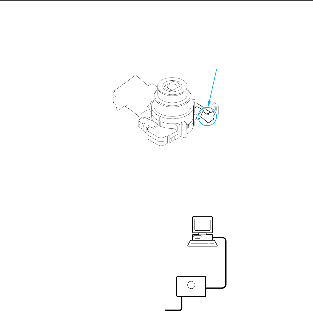
3-22
CHAPTER 3. REPAIR INSTRUCTION
3.3.3 Preparation
Before starting up the Adjustment Software, follow the preparatory steps below:
1. Obtain all the tools necessary for the adjustment.
2. For the Optical Unit Adjustment, jot down the data written on the Optical Unit.
You will need it later.
3. Connect the Camera to the Power Source with the Compact Power Adapter CA-PS500, AC Cable &
DC Coupler DR-500.
4. Set the Replay Mode on the camera and turn on.
5. Set the Communication Mode to Normal.
6. Connect the Camera’s Digital terminal to the PC’s USB Port with INTERFACE CABLE IFC-200
PCU.
7. Turn on the camera.
Note: Perform the preparation in the following order otherwise the camera won’t work properly.
Personal Computer
USB
INTERFACE CABLE
IFC-200PCU
DIGITAL
Compact Power Adapter
CA-PS500
CAMERA BODY
68
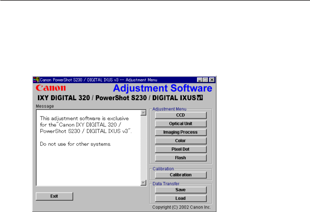
3-23
CHAPTER 3. REPAIR INSTRUCTION
3.3.4 Starting up the Adjustment Software
After completing the preparatory steps, click Start and move the cursor to Program; then select Canon
Digital Camera and click PowerShot S230/DIGITAL IXUS V3 Adjustment.
3.3.5 Menu Window
When the Adjustment Software starts up, the Menu Window below will appear.
3.3.6 How to Use the Adjustment Software
Calibration/Adjustment
For starting, click the button related with adjustment.
* Whenever you use your light source for the adjustment for the first time, be sure to click the “Cali-
bration” Button.
Quitting the Adjustment Software
Click the “Exit” button.
Saving or Loading data
• “Save” button : This button saves all adjustment data stored on the camera in text format.
• “Load” button : This button loads all adjustment data saved in text format to the camera.
Saving or Loading data
• “Save” button : This button saves all adjustment data stored on the camera in text format.
• “Load” button : This button loads all adjustment data saved in text format to the camera.
Notes
• If the adjustment fails, a message indicating the failure will appear on each product. If this happens,
do the adjustment again.
• The Adjustment Software is dedicated only to Canon Digital Camera PowerShot S45.
Never use it for any other camera.
• The Windows98 or 2000 must be pre-installed on the computer that is equipped with the USB
terminal. (Windows95 does not support the USB.)
* The operation with the Windows XP, etc. is not guaranteed.
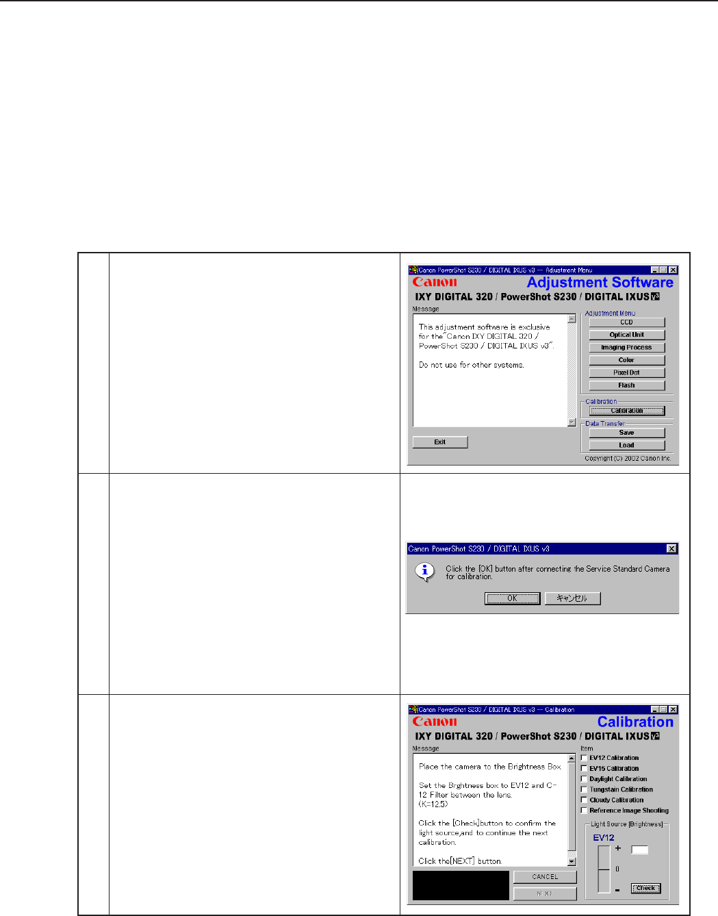
3-24
CHAPTER 3. REPAIR INSTRUCTION
1 Click the “Calibration” button.
3.4 Calibration
3.4.1 Calibration
■Tools Used
• Personal Computer • Brightness Box
(light source A)
• FL-W Filter
• Adjustment Software • Color Viewer
(5600° K)
• ND-2 Filter
• Compact Power Adapter CA-PS500 • Color Bar Chart • ND-4 Filter
• AC Cable • W-10 Filter
(2pcs.)
• ND-8 Filter
• DC Coupler DR-500 • C-12 Filter • Reference Camera
(Merchandise)
• INTERFACE CABLE IFC-200PCU
2 1. When the message on the right appears, check
that the reference camera (Merchandise) is con-
nected to the computer.
2. Click the “OK” button.
3 When the message on the right appears, go to 4.
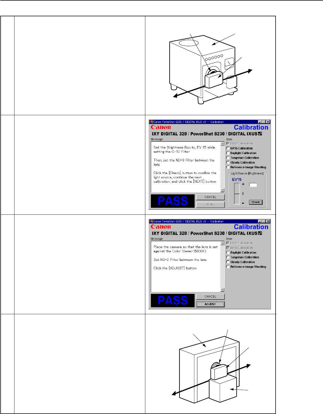
3-25
CHAPTER 3. REPAIR INSTRUCTION
5 1. When the message on the right appears, Set the
Brightness Box to EV15 and attach the ND-8
Filter while setting the C-12 Filter between the
lens.
2. Click the “Check” button.
3. Check the Brightness level if it is within
0 ± 5.
* If not, calibrate the Brightness Box until it
becomes within 0 ± 5.
4. Click the “NEXT” button.
6 When the message on the right appears go to 7.
7 1. Attach the ND-2 Filters between the Lens and
the Color Viewer.
2. Place the camera so that the lens is set against
the center part of the Color Viewer.
3. Click the “ADJUST” button.
Personal
Computer
Power
Source
Brightness
Box
CAMERA
BODY
C-12 Filter
Power
Source
Stand
Color Viewer
Personal
Computer
CAMERA
BODY
ND-2
Filter
4 1. Place the camera so that lens is set against the
light source surface of the Brightness Box via
the C-12 Filter.
2. Set the Brightness Box to EV12.
3. Click the “Check” button.
4. Check the Brightness level if it is within
0 ± 5.
* If not, calibrate the Brightness Box until it
becomes within 0 ± 5.
5. Click the “NEXT” button.
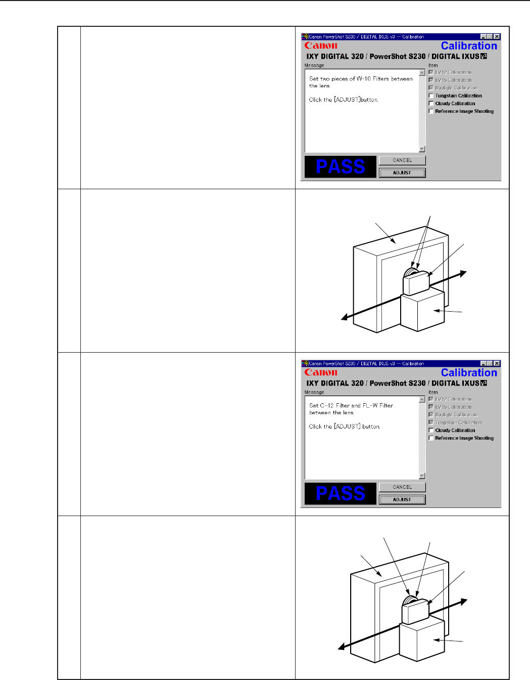
3-26
CHAPTER 3. REPAIR INSTRUCTION
Power
Source
Stand
Color Viewer
Personal
Computer
CAMERA
BODY
W-10
Filter
Power
Source
Stand
Color Viewer
Personal
Computer
CAMERA
BODY
C-12 Filter FL-W Filter
8 When the message on the right appears go to 9.
9 1. Remove the ND-2 Filter.
2. Attach the two W-10 Filters between the Lens
and the Color Viewer.
Place the camera so that the lens is set against
the center part of the Color Viewer.
3. Click the “ADJUST” button.
10 When the message on the right appears go to 11.
11 1. Remove the two W-10 Filters.
2. Attach the C-12 and FL-W Filter between the
Lens and the Color Viewer.
Place the camera so that the lens is set against
the center part of the Color Viewer.
3. Click the “ADJUST” button.
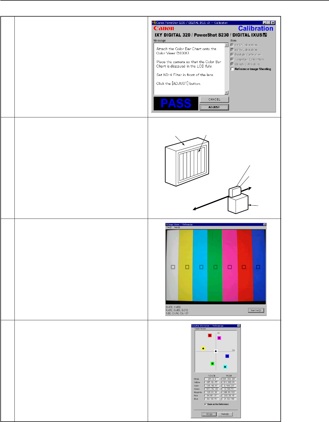
3-27
CHAPTER 3. REPAIR INSTRUCTION
Color Viewer Color Bar Chart
Personal
Computer
CAMERA
BODY
Power
Source
Stand
ND-4
Filter
12 When the message on the right appears go to 13.
13 1. Attach the Color Bar Chart to the Color Viewer.
2. Place the camera so that the Viewing image of
the color bar chart is the full of LCD with the
ND-4 Filter attached.
3. Click the “ADJUST” button.
14 1. Shift a frame on the displayed screen
with a mouse to choose a color of color bar.
2. Click the “Sampling” button.
15 Check “Save as Reference”, and click the “OK”
button to store the data.
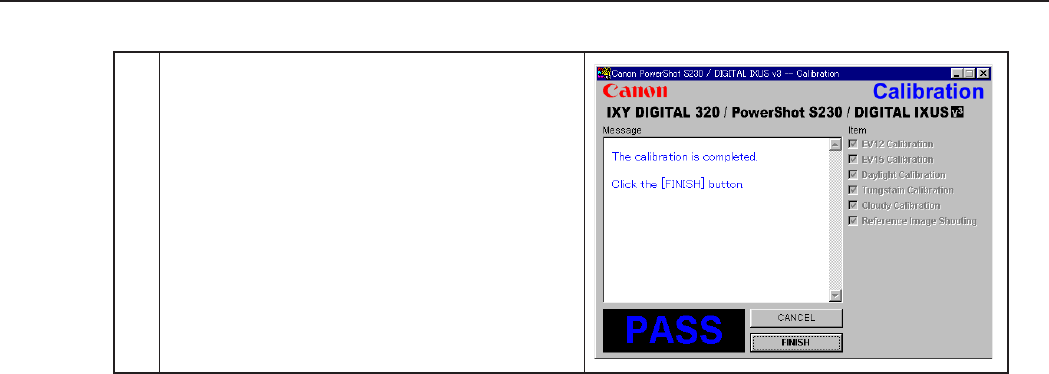
3-28
CHAPTER 3. REPAIR INSTRUCTION
16 When the message on the right appears, click the
“FINISH” button.
(This ends the “Calibration”.)
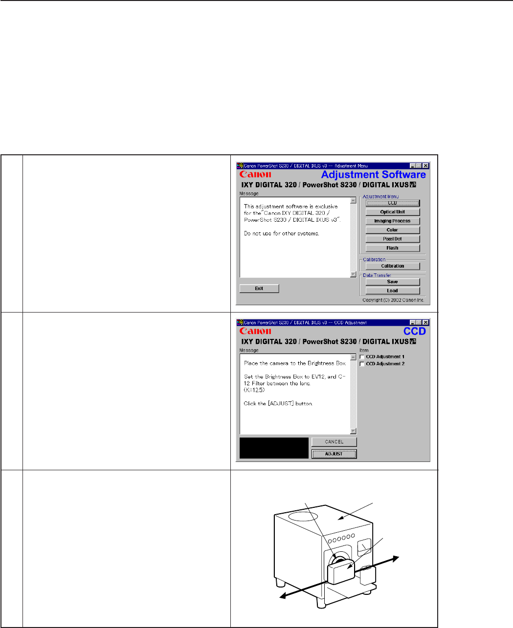
3-29
CHAPTER 3. REPAIR INSTRUCTION
Personal
Computer
Power
Source
Brightness
Box
CAMERA
BODY
C-12 Filter
3.5 Adjustment Procedure
3.5.1 CCD Adjustment
■Tools Used
• Personal Computer • DC Coupler DR-500
• Adjustment Software • INTERFACE CABLE IFC-200PCU
• Compact Power Adapter CA-PS500 • Brightness Box
(light source A)
• AC Cable • C-12 Filter
1 Click the “CCD” button.
2 When the message on the right appears, go to 3.
3 1. Place the camera so that lens is set against the
light source surface of the Brightness Box via
the C-12 Filter.
2. Set the Brightness Box to EV12.
3. Click the “ADJUST” button.
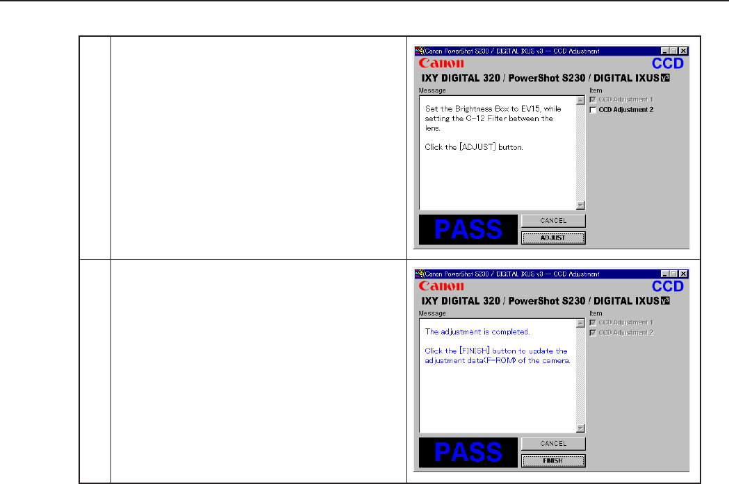
3-30
CHAPTER 3. REPAIR INSTRUCTION
4 When the message on the right appears, Set the
Brightness Box to EV15 while setting the C-12
Filter between the lens.
Click the “ADJUST” button.
5 When the message on the right appears, click the
“FINISH” button.
(This ends the “CCD” Adjustment.)
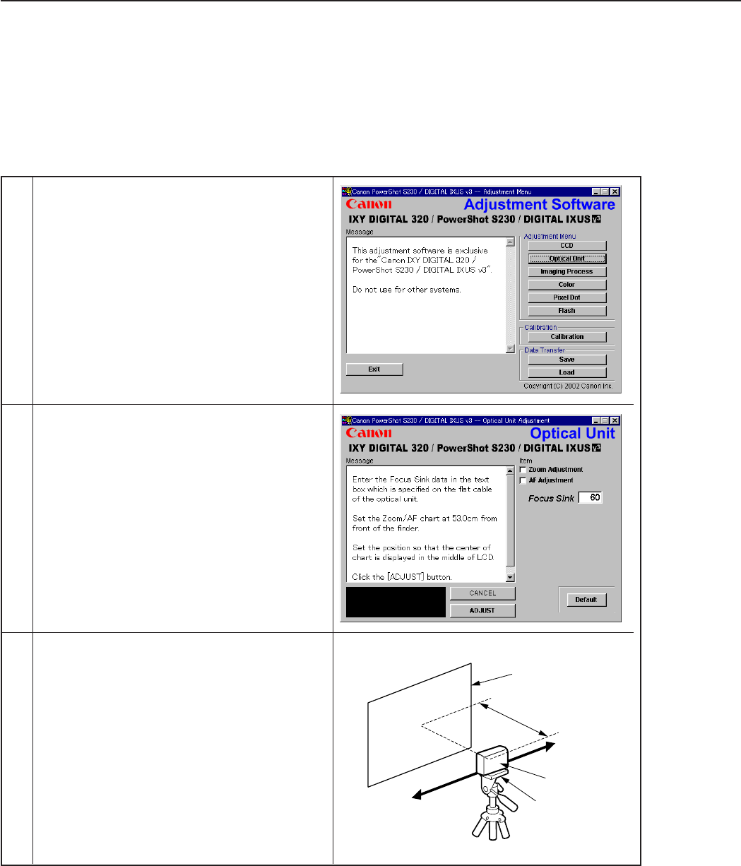
3-31
CHAPTER 3. REPAIR INSTRUCTION
Personal
Computer
Power
Source
52.5cm
Zoom/AF Chart
CAMERA
BODY
Tripod
3.5.2 Optical Unit Adjustment
■Tools Used
• Personal Computer • DC Coupler DR-500
• Adjustment Software • INTERFACE CABLE IFC-200PCU
• Compact Power Adapter CA-PS500 • Zoom/AF Chart
• AC Cable • Tripod
1 Click the “Optical Unit” button.
2 When the message on the right appears, Enter the
value which is written on the flat cable of the
Optical Unit in the text box, go to 3.
3 1. Place the Zoom/AF Chart at 53.0cm away from
the front of the camera finder.
* Place the Zoom/AF Chart on a plain color
wall or equivalent.
* Adjust the light so that the brightness of the
chart will be about EV8.5.
2. Adjust the position of the camera finely so that
the center of the Auto Focus Chart is aligned
with the center of the LCD.
3. Click the “ADJUST” button.
* When the adjustment does not work, click the
“Default” button.
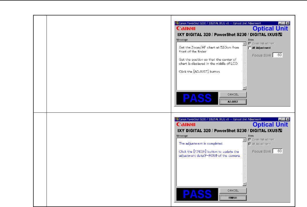
3-32
CHAPTER 3. REPAIR INSTRUCTION
4 When the message on the right appears, click the
“ADJUST” button.
5 When the message on the right appears, click the
“FINISH” button.
(This ends the “Optical Unit” Adjustment.)
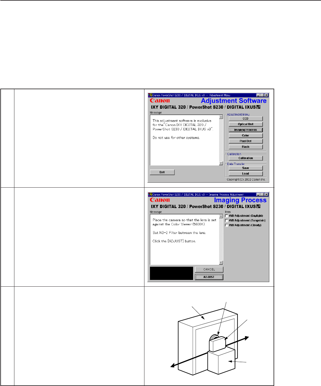
3-33
CHAPTER 3. REPAIR INSTRUCTION
Power
Source
Stand
Color Viewer
Personal
Computer
CAMERA
BODY
ND-2
Filter
3.5.3 Imaging Process Adjustment
■Tools Used
• Personal Computer • Color Viewer (5600° K)
• Adjustment Software • W-10 Filter (2 pcs.)
• Compact Power Adapter CA-PS500 • C-12 Filter
• AC Cable • FL-W Filter
• DC Coupler DR-500 • ND-2 Filter
• INTERFACE CABLE IFC-200PCU
1 Click the “Imaging Process” button.
3 1. Attach the ND-2 Filters between the Lens and
the Color Viewer.
2. Place the camera so that the lens is set against
the center part of the Color Viewer.
3. Click the “ADJUST” button.
2 When the message on the right appears, go to 3.
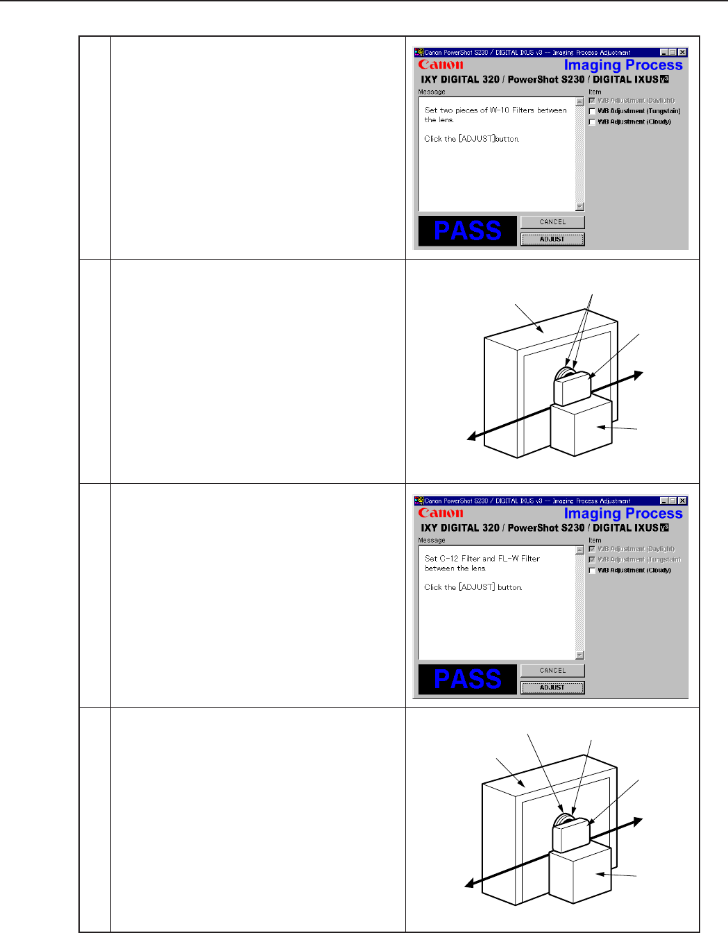
3-34
CHAPTER 3. REPAIR INSTRUCTION
5 1. Remove the ND-2 Filter.
2. Attach the two W-10 Filters between the Lens
and the Color Viewer.
Place the camera so that the lens is set against
the center part of the Color Viewer.
3. Click the “ADJUST” button.
4 When the message on the right appears, go to 5.
6 When the message on the right appears, go to 7.
7 1. Remove the two W-10 Filters.
2. Attach the C-12 and FL-W Filter between the
Lens and the Color Viewer.
Place the camera so that the lens is set against
the center part of the Color Viewer.
3. Click the “ADJUST” button.
Power
Source
Stand
Color Viewer
Personal
Computer
CAMERA
BODY
W-10
Filter
Power
Source
Stand
Color Viewer
Personal
Computer
CAMERA
BODY
C-12 Filter FL-W Filter

3-35
CHAPTER 3. REPAIR INSTRUCTION
8 When the message on the right appears, click the
“FINISH” button.
(This ends the “Imaging Process” Adjustment.)
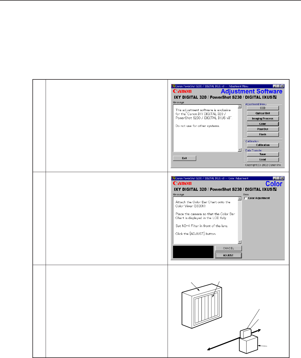
3-36
CHAPTER 3. REPAIR INSTRUCTION
3.5.4 Color Adjustment
■Tools Used
• Personal Computer • INTERFACE CABLE IFC-200PCU
• Adjustment Software • Color Viewer (5600° K)
• Compact Power Adapter CA-PS500 • Color Bar Chart
• AC Cable • ND-4 Filter
• DC Coupler DR-500
1 Click the “Color” button.
Color Viewer Color Bar Chart
Personal
Computer
CAMERA
BODY
Power
Source
Stand
ND-4
Filter
2 When the message on the right appears, go to 3.
3 1. Attach the Color Bar Chart to the Color Viewer.
2. Place the camera so that the Viewing image of
the color bar chart is the full of LCD with the
ND-4 Filter attached.
3. Click the “ADJUST” button.
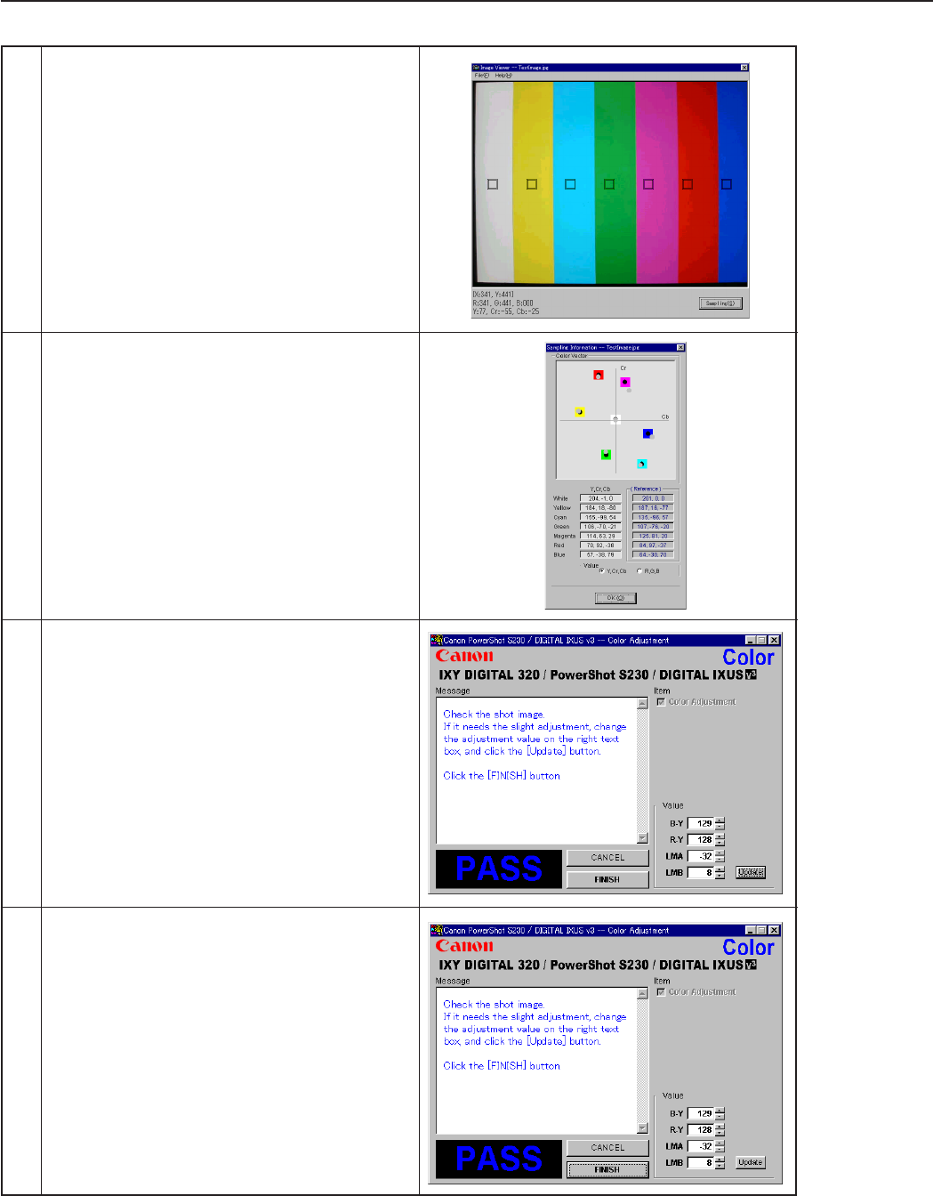
3-37
CHAPTER 3. REPAIR INSTRUCTION
5 Check “Yellow and Red”, and click the “OK”
button.
If these data are within specifications, go to 7.
* Specification
Ave_Cr = Reference Camera ± 10
Ave_Cb = Reference Camera ± 10
6 1. Confirm to see that the image on the PC moni-
tor satisfies the specifications.
2. If the image on the PC monitor does not satisfy
the specifications, change the data using UP,
DOWN button or change the data directly by
typing the data in the text box. Then click the
“UPDATE” button.
4 1. Shift a frame on the displayed screen with
a mouse to choose a color of color bar.
2. Click the “Sampling” button.
7 When the adjustment is completed, click the
“FINISH” button.
(This ends the “Color” Adjustment.)
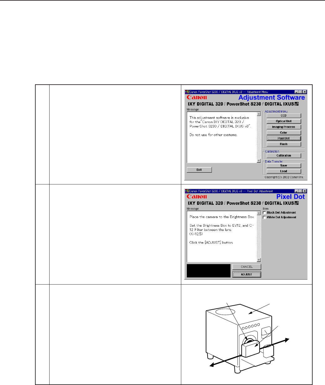
3-38
CHAPTER 3. REPAIR INSTRUCTION
3.5.5 Pixel Dot Adjustment
■Tools Used
• Personal Computer • INTERFACE CABLE IFC-200PCU
• Adjustment Software • Brightness Box (Light source A)
• Compact Power Adapter CA-PS500 • C-12 Filter
• AC Cable • Light-Shielding Cloth (500 × 500 or larger)
• DC Coupler DR-500
1 Click the “Pixel Dot” button.
Personal
Computer
Power
Source
Brightness
Box
CAMERA
BODY
C-12 Filter
2 When the message on the right appears, go to 3.
3 1. Place the camera so that lens is set against the
light source surface of the Brightness Box via
the C-12 Filter.
2. Set the Brightness Box to EV12.
3. Click the “ADJUST” button.
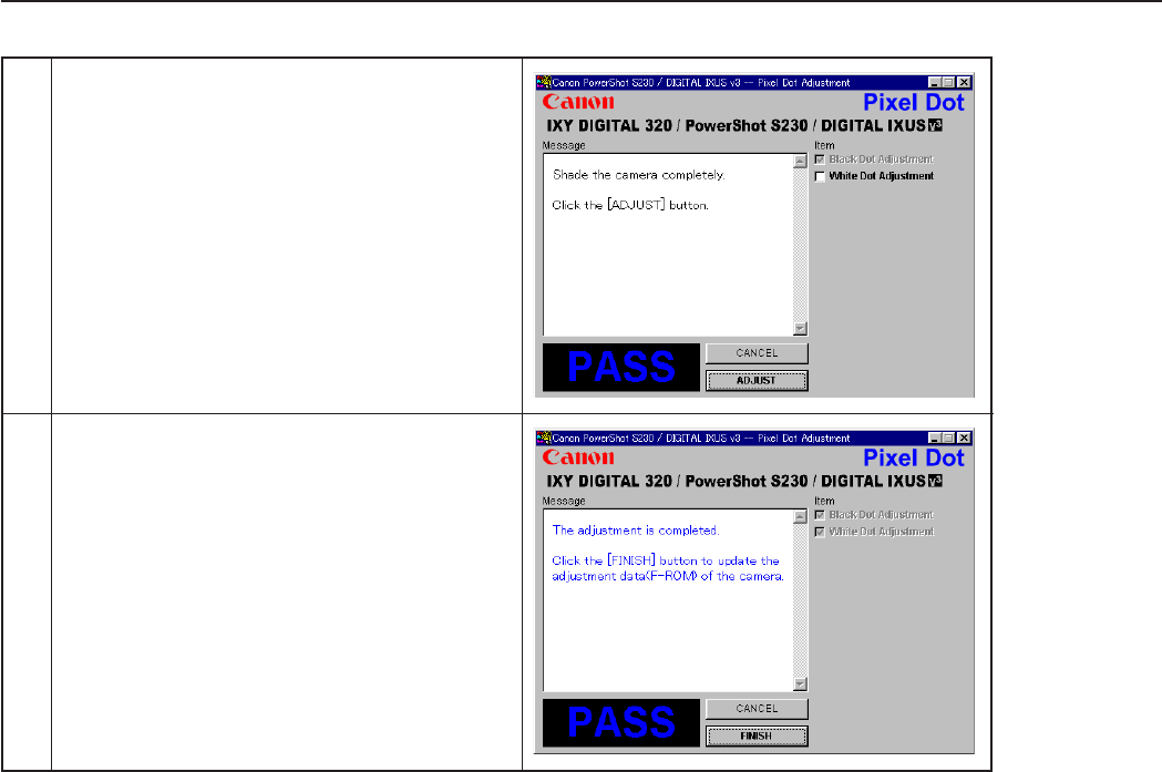
3-39
CHAPTER 3. REPAIR INSTRUCTION
4 1. When the message on the right appears, cover
the camera with the Light-Shielding Cloth so
that the no light reasons the CCD.
2. Click the “ADJUST” button.
5 When the message on the right appears, click the
“FINISH” button.
(This ends the “Pixel Dot” Adjustment.)
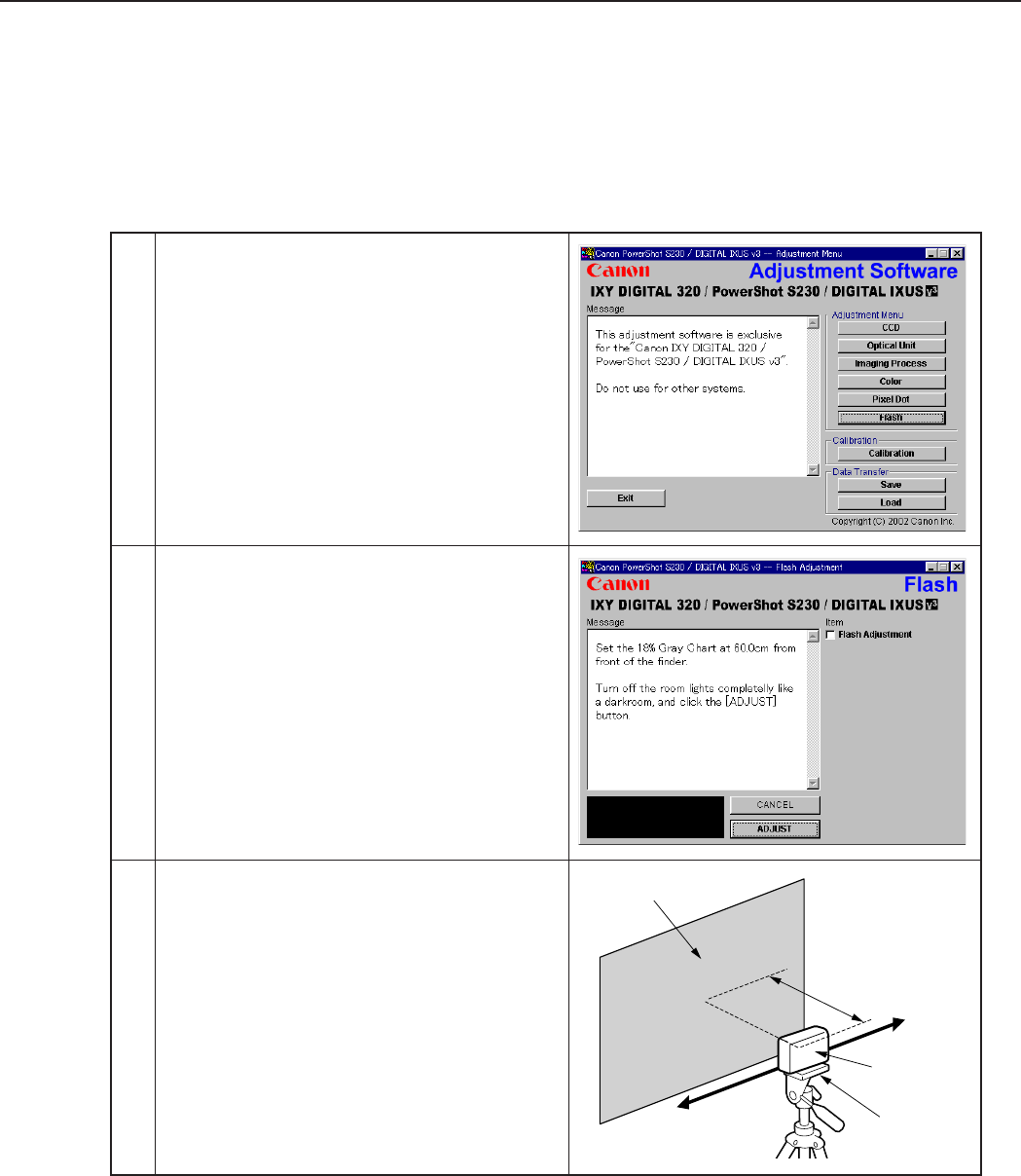
3-40
CHAPTER 3. REPAIR INSTRUCTION
3.5.6 Flash Adjustment
■Tools Used
• Personal Computer • DC Coupler DR-500
• Adjustment Software • INTERFACE CABLE IFC-200PCU
• Compact Power Adapter CA-PS500 • 18% Gray Chart
• AC Cable • Tripod
1 Click the “Flash” button.
2 When the message on the right appears, go to 3.
3 1. Set 18% Gray Chart 60cm from the Finder
front.
2. Make the room as dark as a darkroom.
3. Click the “ADJUST” button.
Personal
Computer
Power
Source
18% Gray Chart
60cm
CAMERA
BODY
Tripod

3-41
CHAPTER 3. REPAIR INSTRUCTION
4 When the message on the right appears, click the
“FINISH” button.
(This ends the “Flash” Adjustment.)

3-42
CHAPTER 3. REPAIR INSTRUCTION
3.5.7 Checking of sound recording/output
It is not required to adjust the recording/output (volume, etc.) of sound.
Check the camera if the sound is recorded/play-backed properly.
CHAPTER 4. PARTS CATALOG
CONTENTS
PowerShot S230/DIGITAL IXUS v3/IXY DIGITAL 320
Casing Parts ----------------------------------------------------------------------------------------------------------------------- Pg1
Internal Parts-1 ------------------------------------------------------------------------------------------------------------------- Pg2
Internal Parts-2 ------------------------------------------------------------------------------------------------------------------- Pg3
OPTICAL UNIT ----------------------------------------------------------------------------------------------------------------- Pg4
Accessories-1 ------------------------------------------------------------------------------------------------------------------------- Pg5
Accessories-2 ------------------------------------------------------------------------------------------------------------------------- Pg6
Accessories-3 ------------------------------------------------------------------------------------------------------------------------- Pg7
Service Tools -------------------------------------------------------------------------------------------------------------------------- Pg8
Category of CLASS
A: Frequency of use: High
B: Frequency of use: Middle
C: Frequency of use: Low
D: Safety-related critical parts
E: Consumable parts
F: Standard screws and washers
S: Supply of the parts is limited

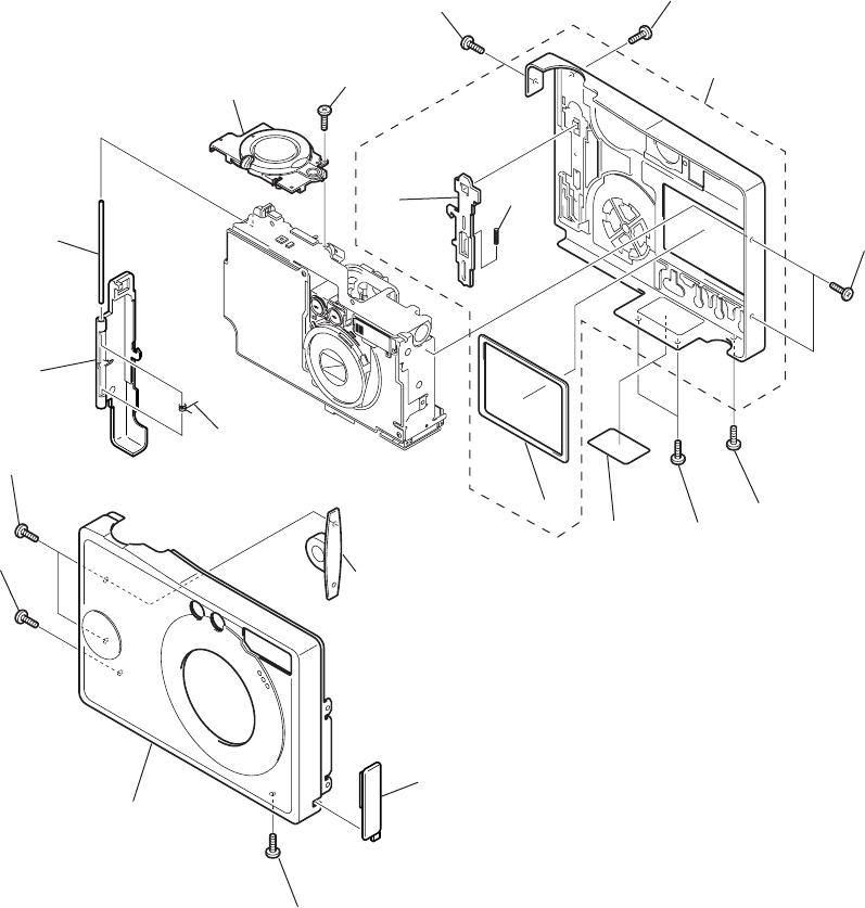
PowerShot S230
DIGITAL IXUS v3
IXY DIGITAL 320
Pg1 Casing Parts
1
18
5
6
7
816
3
4
10 11
12
14
13
14
2
9
17
17
15
15

PARTS LIST
SYMBOL PARTS NO. CLASS QTY DESCRIPTION REMARKS
PowerShot S230
DIGITAL IXUS v3
IXY DIGITAL 320
Pg1
1 CM1-1456-000 B 1 FRONT COVER UNIT IXY DIGITAL 320
CM1-1457-000 B 1 FRONT COVER UNIT PowerShot S230
CM1-1458-000 B 1 FRONT COVER UNIT DIGITAL IXUS v3
2 CY1-6198-000 B 1 PLATE, BODY NUMBER
3 CD1-4240-000 B 1 COVER, JACK
4 CD3-0464-000 B 1 RING, STRAP
5 CD1-4236-020 B 1 COVER, CF
6 CD1-4237-000 C 1 SHAFT, CF COVER
7 CS8-6162-000 C 1 SPRING, CF COVER
8 CM1-1459-000 B 1 SHUTTER BUTTON UNIT
9 CD1-4249-000 C 1 SPACER, LCD
10 CD1-4200-000 C 1 LOCK, CF COVER
11 CS8-5264-000 C 1 SPRING, CF LOCK
12 CM1-1337-000 B 1 REAR COVER UNIT
13 CD1-4183-000 F 1 SCREW
14 CD1-3109-000 F 4 SCREW
15 CD1-4248-000 F 2 SCREW
16 XA4-9170-409 F 1 SCREW
17 CD1-3112-000 F 2 SCREW
18 CD1-3110-000 F 2 SCREW
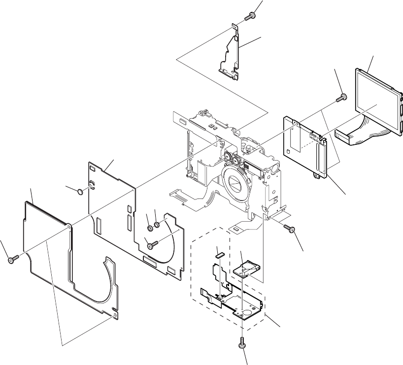
PowerShot S230
DIGITAL IXUS v3
IXY DIGITAL 320
Pg2
14 14
2
4
3
56
8
13
10
9
13
12
11
1
7
13
Internal Parts-1

PARTS LIST
SYMBOL PARTS NO. CLASS QTY DESCRIPTION REMARKS
PowerShot S230
DIGITAL IXUS v3
IXY DIGITAL 320
Pg2
1 CM1-1571-000 C 1 OPERATION KEY UNIT
2 CL1-1113-000 C 1 SHEET, SHIELD
3 WK1-5140-000 C 1 BATTERY, LITHIUM (2ND)
4 CM1-1450-000 C 1 PCB ASS’Y, MAIN
5 CD1-4241-000 C 1 HOLDER, MICROPHONE
6 WR1-5084-000 C 1 MICROPHONE UNIT
7 CD1-4244-000 C 1 SHEET, DUSTPROOF
8 CD1-4234-000 C 1 PLATE, OPERATION
9 WG2-5226-000 C 1 PANEL, LCD
WG2-5226-001 C 1 PANEL, LCD (SELECTION)
10 CM1-1446-000 C 1 BACK LIGHT UNIT
11 CD1-4232-000 C 1 SOCKET, TRIPOD
12 XA1-7170-307 F 2 SCREW
13 CD1-3108-000 F 4 SCREW
14 XA1-7170-357 F 3 SCREW
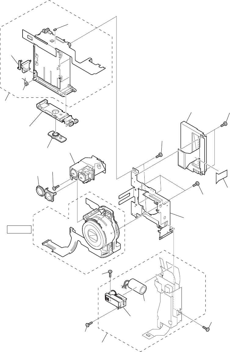
PowerShot S230
DIGITAL IXUS v3
IXY DIGITAL 320
Pg3
1
820
10
11
12
13
9
14
6
5
19
15
7
2
17
18
3
4
16
18
See Pg4
Internal Parts-2

PARTS LIST
SYMBOL PARTS NO. CLASS QTY DESCRIPTION REMARKS
PowerShot S230
DIGITAL IXUS v3
IXY DIGITAL 320
Pg3
1 CM1-1447-000 C 1 FLASH/DC UNIT
2 CD1-4444-000 C 1 SHEET, NOISE ABSORPTION
3 CM1-1342-000 C 1 FLASH UNIT
4 CK9-0308-000 C 1 CAPACITOR, ELECT. 330V 80µF
5 CM1-1452-000 C 1 CF UNIT
6 WD1-5064-000 C 1 FUSE, MATSU.DENKI UNHH206
7 CD1-4231-010 C 1 FRAME, MAIN
8 CD1-4180-000 C 1 RUBBER, FINDER
9 CD1-4217-000 C 1 LOCK, BATTERY
10 CM1-1340-010 C 1 FINDER UNIT
11 CD1-4239-000 B 1 COVER, DC COUPLER
12 CD1-4238-000 B 1 COVER, BATTERY
13 CM1-1460-000 C 1 BATTERY BOX UNIT
14 CS8-6161-000 C 1 SPRING, BATTERY LOCK
15 XA4-5170-309 F 3 SCREW
16 CD1-3108-000 F 1 SCREW
17 CD1-3105-000 F 2 SCREW
18 XA1-7140-307 F 2 SCREW
19 XA4-9170-359 F 2 SCREW
20 XA4-9140-357 F 1 SCREW
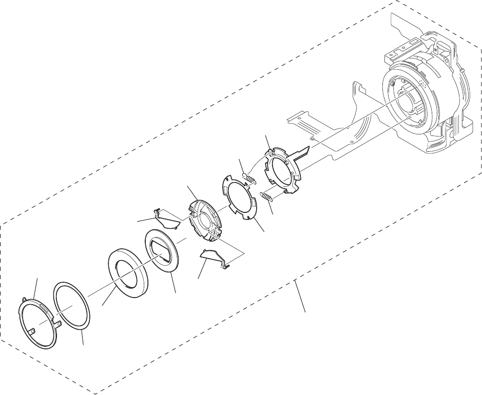
PowerShot S230
DIGITAL IXUS v3
IXY DIGITAL 320
Pg4
12
3
3
4
5
6
7
8
9
10
11
OPTICAL UNIT

PARTS LIST
SYMBOL PARTS NO. CLASS QTY DESCRIPTION REMARKS
PowerShot S230
DIGITAL IXUS v3
IXY DIGITAL 320
Pg4
1 CD1-3033-000 B 1 CAP, BARREL1
2 CD1-3034-010 B 1 CAP, FRONT
3 CD1-4171-000 B 2 PLATE, BARRIER
4 CD1-4172-000 C 1 BASE, BARRIER
5 CD1-3042-010 C 1 PLATE, BARRIER DRIVE
6 CS8-5204-000 C 1 SPRING, BARRIER OPEN
7 CS8-5205-000 C 1 SPRING, BARRIER CLOSE
8 CD1-4173-000 C 1 RING, BARRIER DRIVE
9 CM1-2022-000 C 1 OPTICAL UNIT
10 CD1-4169-000 C 1 CAP, BASE BARREL
11 CD1-3036-000 C 1 SHEET, LENS BARREL
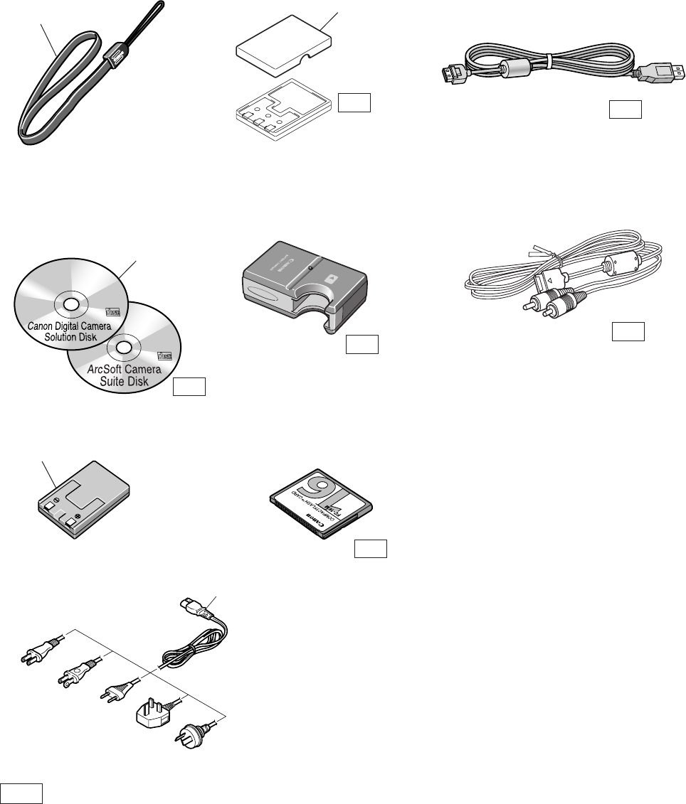
PowerShot S230
DIGITAL IXUS v3
IXY DIGITAL 320
Pg5
N.Sl : N.S Stand for No Stock (Product available)
Accessories-1
Wrist Strap WS-110 TERMINAL COVER NB-1LH USB Interface Cable
IFC-200PCU
AV Cable AVC-DC200Battery Charger
CB-2LS/2LSE
Canon Digital Camera
Solution Disk,
ArcSoft Camera Suite Disk
DC Coupler DR-500
AC Cable
N.S
N.S
N.S
N.S
1
3
2
5
N.S
CF Card FC-16M
N.S
4
PLUG TYPE
N
J
E
B
A

PARTS LIST
SYMBOL PARTS NO. CLASS QTY DESCRIPTION REMARKS
PowerShot S230
DIGITAL IXUS v3
IXY DIGITAL 320
Pg5
1 CD1-3113-000 B 1 WRIST STRAP WS-110
2 C84-1132-000 S 1 CD-ROM, SOLUTION VER.11 (J/E) FOR JAPAN, ASIA,
AUSTRALIA
C84-1138-000 S 1 CD-ROM, SOLUTION VER.11 (E/F/S) FOR USA, CANADA
3 C84-1044-000 B 1 DC COUPLER DR-500
4 D82-0641-000 C 1 CABLE, AC (J) FOR JAPAN
D82-0642-000 C 1 CABLE, AC (N) FOR USA, CANADA
D82-0643-000 C 1 CABLE, AC (E) FOR EUROPE, ASIA
D82-0644-000 C 1 CABLE, AC (B) FOR ASIA
D82-0645-000 C 1 CABLE, AC (A) FOR AUSTRALIA
5 CD1-4329-000 B 1 COVER, TERMINAL NB-1LH
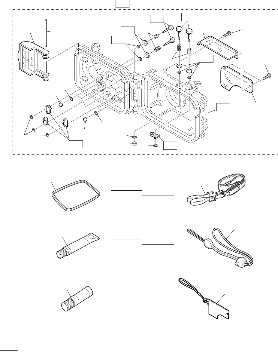
PowerShot S230
DIGITAL IXUS v3
IXY DIGITAL 320
Pg6
N.Sl : N.S Stand for No Stock (Product available)
Accessories-2
Waterproof Seal
Silicone Grease
Anti-Condensation Solution
Neck Strap
Wrist Strap
Diffusion Plate Unit
Waterproof Case WP-DC 600
N.S
N.S
N.S
N.S
N.S
N.S
N.S
N.S N.S
11
1
1
1
36
2
2
2
4
4
58
8
7
12
13
14
9
10
11

PARTS LIST
SYMBOL PARTS NO. CLASS QTY DESCRIPTION REMARKS
PowerShot S230
DIGITAL IXUS v3
IXY DIGITAL 320
Pg6
1 CY1-6168-000 C 10 E RING
2 CY1-6169-000 C 6 CAP, BUTTON
3 CY1-6171-000 C 1 BUCKLE ASS’Y
4 CY1-6167-000 C 10 SPRING, COIL
5 CY1-6202-000 C 1 HOLDER, DIFFUSION PLATE
6 CYI-6203-000 C 1 SHAFT, BUCKLE
7 CYI-6201-000 C 1 PROTECTOR, DIFFUSION PLATE
8 CY6-3210-000 C 4 SCREW
9 CY1-6177-000 B 1 PACKING, RUBBER
10 DY9-3029-000 C 1 GREASE, PACKING
11 DY9-3028-000 C 1 CLEANER, ANTI-FOGGING LIQUID
12 CY1-6099-000 B 1 STRAP, NECK
13 CY1-6174-000 B 1 STRAP, WRIST
14 CY1-6178-000 B 1 DIFFUSION PLATE UNIT
PowerShot S230
DIGITAL IXUS v3
IXY DIGITAL 320
Pg7
Accessories-3
Camera User Guide
Software Starter Guide
System Map
1
2
3
Quick Start Guide
4

PARTS LIST
SYMBOL PARTS NO. CLASS QTY DESCRIPTION REMARKS
PowerShot S230
DIGITAL IXUS v3
IXY DIGITAL 320
Pg7
1 CDI-E072-000 S 1 I.BOOK(E) PS S230/IXUS V3 FOR USA, CANADA,
ASIA, AUSTRALIA
CDI-S062-000 S 1 I.BOOK(S) PS S230 FOR USA
CDI-J063-000 S 1 I.BOOK(J) IXY DIGITAL 320 FOR JAPAN
CDI-F061-000 S 1 I.BOOK(F) PS S230 FOR CANADA
2 CDI-E071-000 S 1 SOFTWARE GUIDE(E) VER.11 FOR USA, CANADA,
ASIA, AUSTRALIA
CDI-S061-000 S 1 SOFTWARE GUIDE(S) VER.11 FOR USA
CDI-J062-000 S 1 SOFTWARE GUIDE(J) VER.11 FOR JAPAN
CDI-F060-000 S 1 SOFTWARE GUIDE(F) VER.11 FOR CANADA
3 CDI-E073-000 S 1 SYSTEM MAP(E) PS S230/IXUS V3 FOR USA, CANADA,
ASIA, AUSTRALIA
CDI-S063-000 S 1 SYSTEM MAP(S) PS S230 FOR USA
CDI-J064-000 S 1 SYSTEM MAP(J) IXY DIGITAL 320 FOR JAPAN
CDI-F062-000 S 1 SYSTEM MAP(F) PS S230 FOR CANADA
4 CDI-E074-000 S 1 QUICK START GUIDE(E) FOR USA, CANADA,
ASIA, AUSTRALIA
CDI-S064-000 S 1 QUICK START GUIDE(S) FOR USA
CDI-J065-000 S 1 QUICK START GUIDE(J) FOR JAPAN
CDI-F063-000 S 1 QUICK START GUIDE(F) FOR CANADA
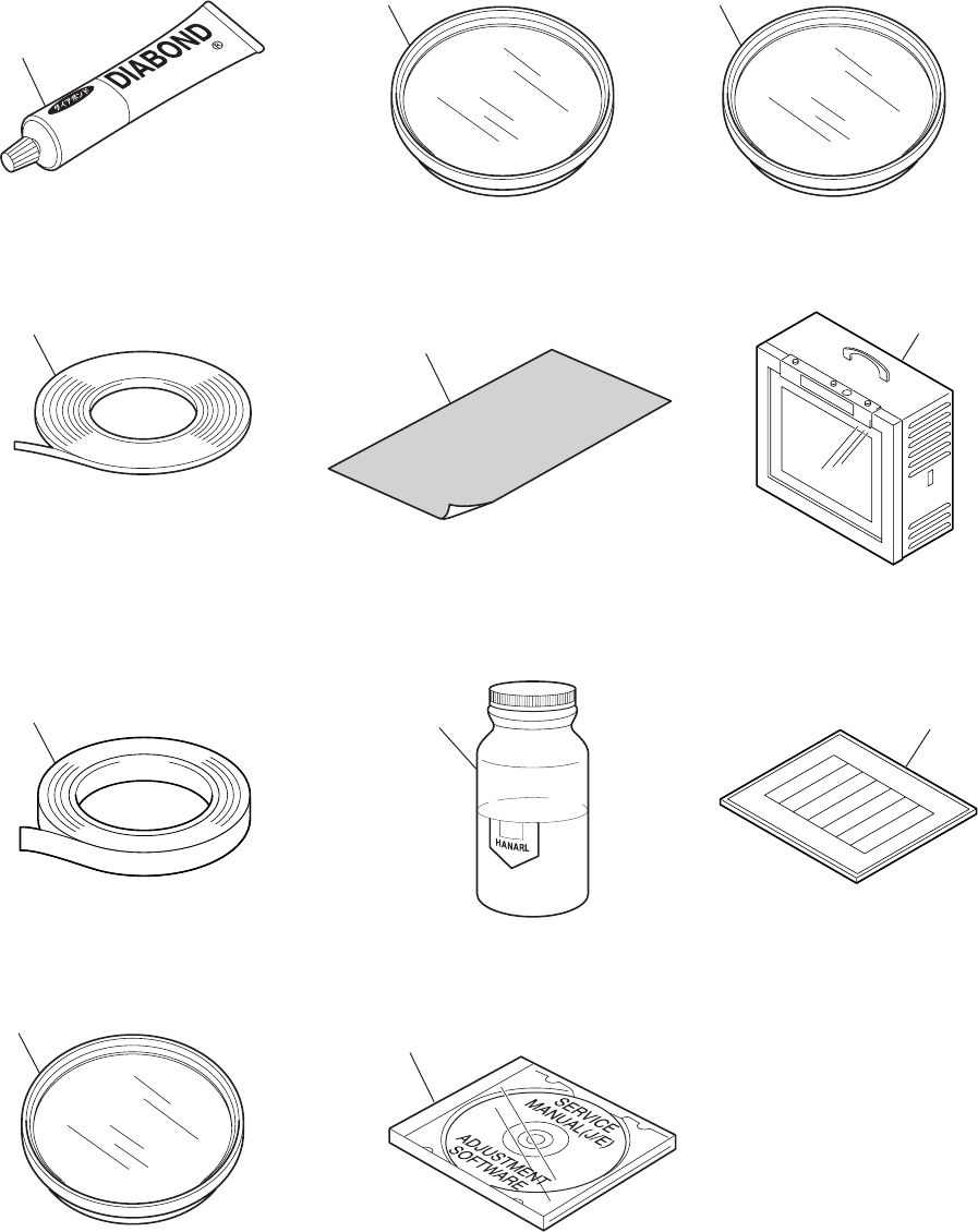
Service Tools
PowerShot S230
DIGITAL IXUS v3
IXY DIGITAL 320
Pg8
DIA BOND NO.1663G BLACK W-10 Filter
18% Gray Chart
HANARL FL-778
SERVICE MANUAL CD-ROM
Adhesive Tape SONY T4000
Adhesive Tape 3M NO.56
C-12 Filter
1
4
2
3
5
FL-W Filter
Color Viewer (5600° K)
Standard Color Bar Chart
9
11
10
6
8
7

PARTS LIST
SYMBOL PARTS NO. CLASS QTY DESCRIPTION REMARKS
PowerShot S230
DIGITAL IXUS v3
IXY DIGITAL 320
Pg8
1 CY9-8129-000 Y 1 BOND, DIA BOND NO.1663G BLACK
2 CY4-6012-000 Y 1 ADHESIVE TAPE, SONY T4000 6mm × 50m roll
3 CY4-6018-000 Y 1 ADHESIVE TAPE, 3M NO.56 15mm × 66m roll
4 DY9-2029-000 Y 1 FILTER, C-12
5 CY9-1543-000 Y 1 FILTER, W-10
6 CY4-6016-000 Y 1 CHART, 18% GRAY
7 DY9-3026-010 Y 1 LUBE, HANARL FL-778, OIL
8 CY8-4380-031 Y 1 CD-ROM, SERVICE MANUAL (J/E)
9 CY9-1550-000 Y 1 FILTER, FL-W
10 DY9-2039-100 Y 1 COLOR VIEWER 5600K
11 DY9-2002-000 Y 1 COLOR BAR CHART

CHAPTER 5. DIAGRAMS
CONTENTS
1. INTERCONNECTION DIAGRAM
2. BLOCK DIAGRAMS
2-1. OVERALL
2-2. MAIN PCB ASS’Y (1/3)
2-3. MAIN PCB ASS’Y (2/3)
2-4. MAIN PCB ASS’Y (3/3)
2-5. FLASH/DC UNIT
2-6. Abbreviation in Block Diagrams
3. P.C.B. DIAGRAMS
3-1. MAIN PCB ASS’Y
3-2. FLASH/DC UNIT
3-3. OPTICAL UNIT
3-4. BATTERY BOX UNIT
3-5. CF UNIT
3-6. OPERATION KEY UNIT

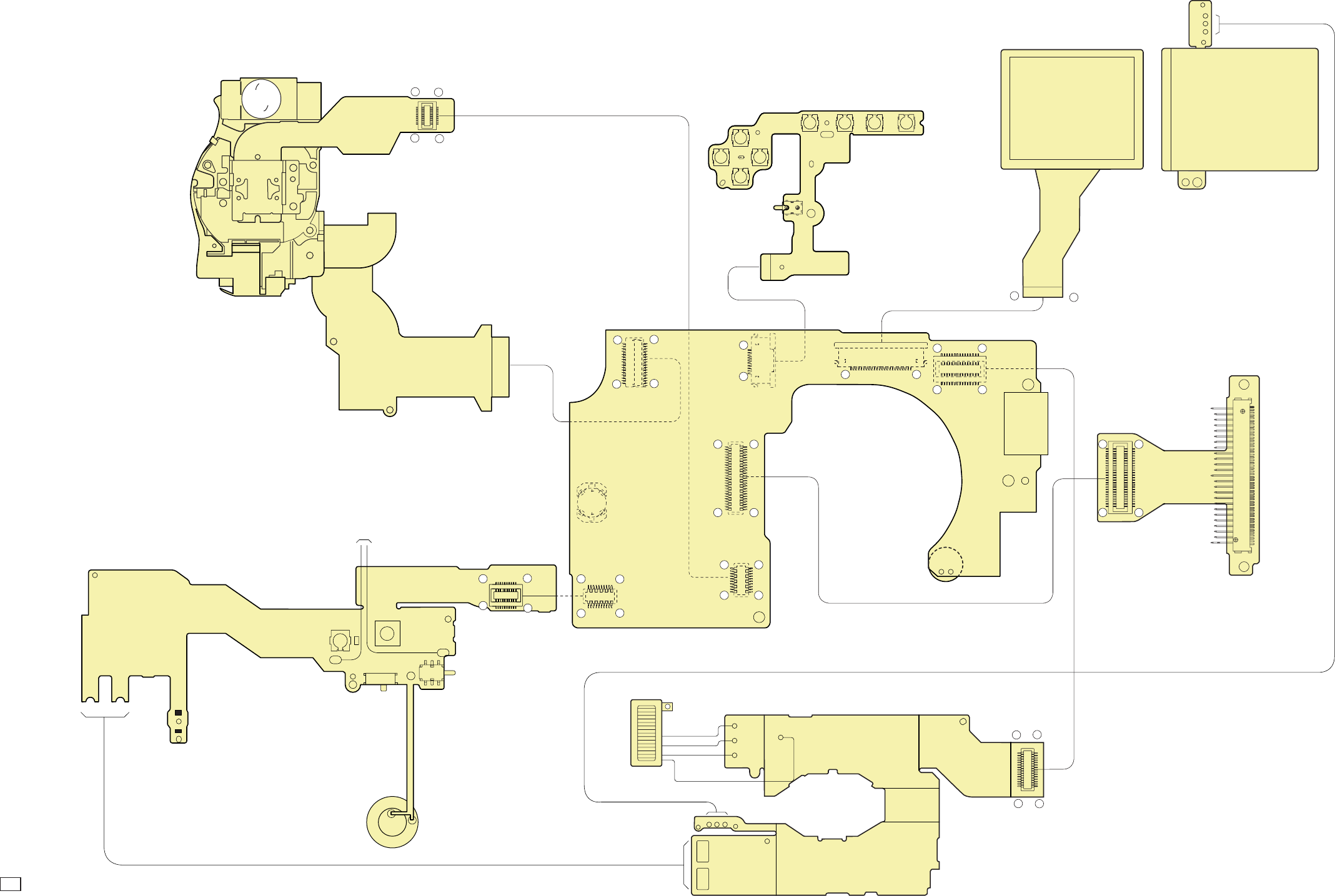
C CANON INC., 2002
01 OCTOBER, 2002
1. INTERCONNECTION DIAGRAM
1
11
20
10 1
25
115
16 30
2650
1
33
32
CN1901 CN1004
115
16 30
CN101
CN1005
1
25
2650
CN1301
110
CN1002
124
1
11 20
10
CN1003
CN1501
BACK LIGHT UNIT
CF UNIT
LCD PANEL
124
Battery Open
Detect SW
CN601
CN602
ORG
WHT
Button
BATTERY
FLASH FLASH/DC UNIT
USB,AVOUT
MAIN PCB ASS'Y
OPERATION KEY UNIT
Board To Board
Board To Board
MIC
CN1502
BLK
GRY
Board To Board
10
20
11
1
CN301
OPT FPC
CCD FPC
OPTICAL UNIT
VF
2
1
11 20
10
CF Open
Detect SW
RLS FPC
FINDER LED
Mode SW
CN401
POWER SW
BUZZER
Board To Board
Release SW
BATTERY
BATTERY BOX UNIT

C CANON INC., 2002
01 OCTOBER, 2002
MAIN PCB ASS’Y
CONNECTORS
CN1002
1 SCAN
2 BTOP
3UP
4 LEFT
5 LED_POWERAN
6 LED_POWER
7 DOWN
8 RIGHT
9 EXP/WB/ERASE
10 DISP
11 MINUS
12 SET
13 M_GND
14 M_GND
CN1003
1 M_GND
2 VCC1
3 LED_GREEN
4 LED_ORANGE
5 LED_MACRO
6 POWER
7 M_GND
8 C_GND
9 C_GND
10 MODE1
11 MODE0
12 SCAN
13 SW1
14 SW2
15 VBATTEP
16 BUZZER
17 CFOP
18 TELE
19 WIDE
20 M_GND
CN1004
1 Not Connected
2 VEE2
3 VDD3
4 E1PLAT
5 VCC1L
6 VCC1L
7 VDD2
8 VBATT
9 VBATT
10 VCC1SD
11 VCC1SD
12 EFCHG
13 LED_BL
14 STSP
15 VCHGLVL
16 C_GND
17 C_GND
18 C_GND
19 VCC2RE
20 E3LAT
21 VCC2AFE
22 E2LAT
23 VBATT
24 VBATT
25 VCC1A
26 VCC1
27 VCC1
28 M_GND
29 M_GND
30 M_GND
CN1005
1 /CE1
2 /CE2
3 A10
4 /VS1
5 /OE
6 /IORD
7 A09
8 /IOWR
9 A08
10 /WE
11 A07
12 IREQ
13 VCC1
14 VCC1
15 A06
16 Not Connected
17 A05
18 /VS2
19 A04
20 RESET
21 A03
22 /WAIT
23 A02
24 Not Connected
25 A01
26 C_GND
27 /CD1
28 D03
29 D11
30 D04
31 D12
32 D05
33 D13
34 D06
35 D14
36 D07
37 D15
38 /REG
39 A00
40 Not Connected
41 D00
42 Not Connected
43 D01
44 D08
45 D02
46 D09
47 /IOIS16
48 D10
49 /CD2
50 C_GND
CN1301
1 C_GND
2 C_GND
3 C_GND
4RG
5V1
6 V3A
7 CSUB
8V4
9H1
10 H2
11 GND
12 VOUT
13 VDD
14 V2
15 SUB
16 V3B
17 VL
18 V5A
19 V5B
20 V6
CN1501
1 UV_GND
2 Not Connected
3 Not Connected
4 Not Connected
5 Not Connected
6 VBUS
7 VIDEO
8 VC_DET
9D-
10 D+
11 AUDIO
12 UV_GND
CN1502
1 Not Connected
2 RGT
3 BLUE
4 RED
5 GREEN
6 PSIG
7 HCK1
8 HCK2
9 CEXT/REXT
10 Not Connected
11 REF
12 HST
13 WIDE
14 Not Connected
15 VSSG
16 VDDG
17 VSS
18 VDD
19 DWN
20 EN
21 VCK
22 VST
23 COM
24 Not Connected
CN1901
1 SLNT_AN
2 SLNT_DET0
3 SLNTZM_COM
4 SLNTZM_COM
5 ZMPI_AN
6 ZMPO0
7 SLNT_AN
8 SLNT_DET1
9 ZMO+
10 ZMO+
11 ZMO-
12 ZMO-
13 AFLEDAN
14 AFLEDK
15 ZMPI_AN
16 ZM_RST
17 SH+ AFA+
18 SH+ AFA+
19 SH-
20 SH-
21 IR-
22 IR-
23 IR+ AFB-
24 IR+ AFB-
25 AFB+
26 AFB+
27 AFA-
28 AFA-
29 ZMAFPI_COM
30 ZMPI_AN
31 ZMPO1
32 AFPI_AN
33 AFRST
CN301
1 GND
2 GND
3 GND
4RG
5V1
6 V3A
7 CUSB
8V4
9H1
10 H2
11 GND
12 VOUT
13 VDD
14 V2
15 SUB
16 V3B
17 VL
18 V5A
19 V5B
20 V6
CN401
1 M_GND
2 VCC1
3 LED_GREEN
4 LED_ORANGE
5 LED_MACRO
6 POWER
7 M_GND
8 C_GND
9 C_GND
10 MODE1
11 MODE0
12 SCAN
13 SW1
14 SW2
15 VBATTEP
16 BUZZER
17 CFOP
18 TELE
19 WIDE
20 M_GND
CN601
1 /CE1
2 /CE2
3 A10
4 /VS1
5 /OE
6 /IORD
7 A09
8 /IOWR
9 A08
10 /WE
11 A07
12 IREQ
13 VCC1
14 VCC1
15 A06
16 Not connected
17 A05
18 /VS2
19 A04
20 RESET
21 A03
22 /WAIT
23 A02
24 Not connected
25 A01
26 C_GND
27 /CD1
28 D03
29 D11
30 D04
31 D12
32 D05
33 D13
34 D06
35 D14
36 D07
37 D15
38 /REG
39 A00
40 Not connected
41 D00
42 Not connected
43 D01
44 D08
45 D02
46 D09
47 /IOIS16
48 D10
49 /CD2
50 C_GND
BATTERY BOX UNITOPTICAL UNIT CF UNIT FLASH/DC UNIT
CN602
1 GND
2 D03
3 D04
4 D05
5 D06
6 D07
7 /CE1
8 A10
9 /OE
10 A09
11 A08
12 A07
13 VCC
14 A06
15 A05
16 A04
17 A03
18 A02
19 A01
20 A00
21 D00
22 D01
23 D02
24 /IOIS16
25 /CD2
26 /CD1
27 D11
28 D12
29 D13
30 D14
31 D15
32 /CE2
33 /VS1
34 /IORD
35 /IOWR
36 /WE
37 IREQ
38 VCC
39 Not connected
40 /VS2
41 RESET
42 /WAIT
43 Not connected
44 /REG
45 Not connected
46 Not connected
47 D08
48 D09
49 D10
50 GND
CN101
1 Not Connected
2 VEE2
3 VDD3
4 E1PLAT
5 VCC1L
6 VCC1L
7 VDD2
8 VBATT
9 VBATT
10 VCC1SD
11 VCC1SD
12 EFCHG
13 LED_BL
14 STSP
15 VCHGLVL
16 C_GND
17 C_GND
18 C_GND
19 VCC2RE
20 E3LAT
21 VCC2AFE
22 E2LAT
23 VBATT
24 VBATT
25 VCC1A
26 VCC1
27 VCC1
28 M_GND
29 M_GND
30 M_GND
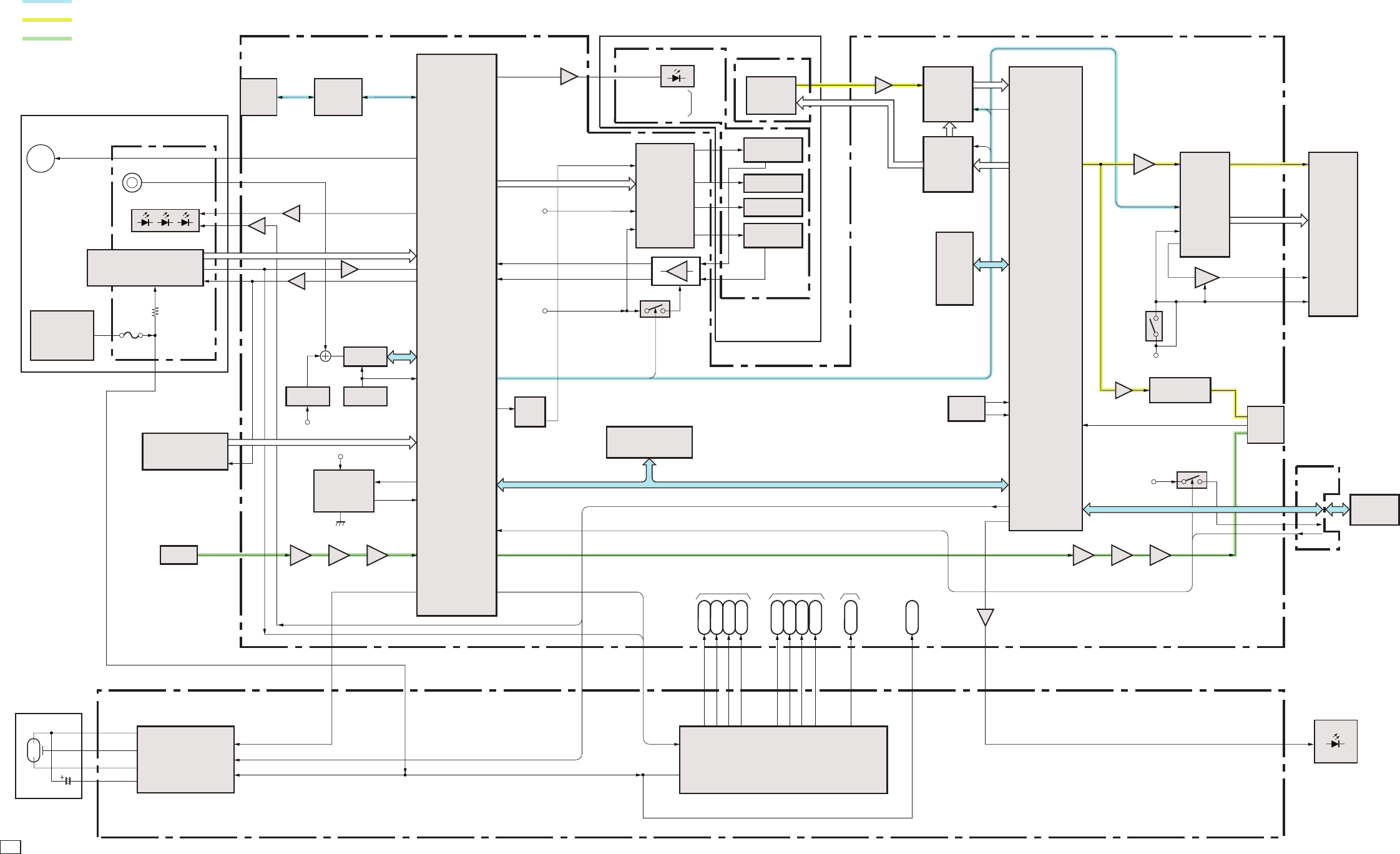
C CANON INC., 2002
01 OCTOBER, 2002
2. BLOCK DIAGRAMS
2.1 OVERALL
Button BATTERY
AV OUT
FLASH
HV/OSC/XE_Drive
VCC 1
VCC 1L
VCC 1A
CCD
Sensor
Zoom Motor
Motor Driver
IRIS Motor
AF Motor
SHUTER Motor
Digital
Signal
Processing
IC
LCD
PANEL
BACK LIGHT
UNIT
CF Card
DATA COMMUNICATION
ANALOG IMAGE SIGNAL
ANALOG AUDIO SIGNAL
VCC 1SD
VDD2
VCC 2AFE
VEE 2
VCC 2RE
VDD3
VBATT
CF UNIT
VCC1
VDD3
Filter, Drive
CDS, A/D
TG
SDRAM
OSC
L.P.F Line AmpBuf. Amp
L.P.FALC AmpMIC Amp
DC/DC CONVERTER
FLASH/DC UNIT
for System
Control for LCD
for CCD
EVR
FLASH MEMORY
VCC1
AF Suport
SELF
Red Eye
LED
VBATT
CPU
USB
Control
USB CN1501
2/2
Buzzer
OPRATION Switch
OPRATION KEY
UNIT
BATTERY BOX
VBATT
VBATT
RESET
RTC
+3.3VREG
MIC
BATTERY BOX UNIT
OPTICAL UNIT
MAIN PCB ASS’Y
CCD FPC
OPT FPC
RLS FPC
FINDER LED
CN1501
1/2
LCD
Driver
BATTERY
Lord Test
LCD
CONTROL
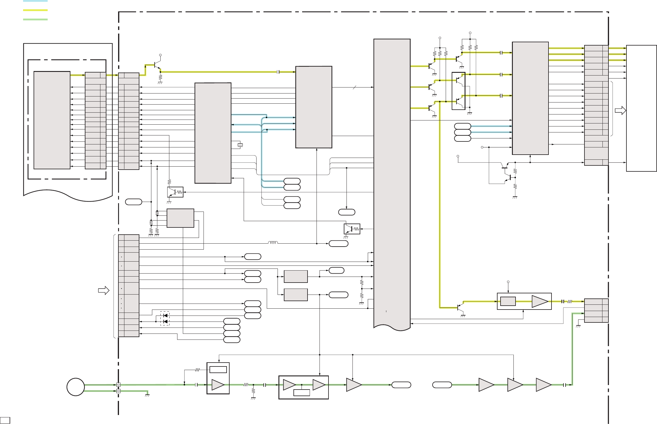
C CANON INC., 2002
01 OCTOBER, 2002
2.2 MAIN PCB ASS’Y (1/3)
MAIN PCB ASS’Y (1/3)
CCD FPC
OPTICAL UNIT 1/2
IC1011 (1/3)
Digital Signal Processing IC
T8F80XB-0001
VCC1
VDD
DAOUT
10
D0
ı
D9
P3_6
CCD2
ı
CCD11
AD_D0
ı
AD_D9
DATA COMMUNICATION
ANALOG IMAGE SIGNAL
ANALOG AUDIO SIGNAL
CN1502
18
8
7
12
19
20
21
22
11
23
3
5
4
13
2
REF
COM
BLUE
GREEN
RED
VDD
RGT
HST
HCK1
HCK2
EN
VCK
VST
DWN
WIDE
RGT
HST
HCK1
HCK2
WIDE
7
AUDIO
8
VC_DET
11
UV_GND 12
VIDEO
LCD PANEL
6
PSIG
CN301
13
17
9
18
6
16
8
19
20
15
7
14
5
12 12
10
4
13
17
9
18
6
16
8
19
20
15
7
14
5
10
4
V1
V2
V4
V6
V3A
V5A
V5B
V3B
V1
V2
V4
V6
V3A
V5A
V5B
V3B
SUB
CSUB
VoutVout
RG
H2
H1
VL
VDD
V1
V2
V4
V6
V3A
V5A
V5B
V3B
SUB
CSUB
RG
H2
H1
VL
VDD
SUB
CSUB
RG
H2
H1
VL
VDD
CN1301
Vout
CN1004 1/2
6
25
3
8
9
23
24
19
4
22
20
5
27
26
11
10
21
2
7
VCC1A
VBATT
E2LAT
E3LAT
E1PLAT
VCC2RE E1LAT
E2LAT
E21LAT
E3LAT
VDD2
VDD3
VCC2AFE
VCC1
VCC1L
VCC1SD
VEE2
MIC
From FLASH/DC UNIT
VCC1A
VCC1A_3
VCC2_AD
APVD
VDD3
VBATT
VCC2RE
POWER
EX38
EX37
EX36
EX35
EX12
EX11
EX9
EX3
EX0
EX1
EX13
EX10
BUFFER
+Av+1+1 +1
ADIN _2
AV OUT
CCD
Sensor
12
10
9
8
7
3
4
2
1
17
18
14
13
20
21
22
VDD
Q1301
BUFFER
2SC4617
Q1303
VSUB CONT
PDTC144EE
IC1303
CCD POWER REG
BD3987FV
IC1702
MIC Amp
NJM2118V IC1704
ALC Amp
AN6123MS
IC1701(1/2)
L.P.F
TC75W51FK
IC1705 2/2
LINE Amp
TC75W60FK
IC1705 1/2
L.P.F
TC75W60FK
C1704 C1711
1
3
8
73
DET gm
55 7
AUDIO_REC AUDIO_PB
IC1701(2/2)
BUF. Amp
TC75W51FK
31713 5 C1719
IC1014
IC1006
45
45
2
+3.0V REG
TK11130CS
+2.5V REG
TK11125CS
TG_HD
AD_LD
TG_CS
SDATA2
SDATA2
X1301
45MHz
SDATA
CS
SCLK2
SPBLK
SPSIG
PBLK
ADCLK
CLPOB2
SCLK2 SCK
C1318
43
22
39
46
38
40
42
47
48
12
13
9
4
2
6
8
1
5
3
41
45
12
14
17
16
35
34
30
31
33
32
27
28
44
15
AL_LD
TG_CS
OBP
CDSIN
IC1302 CDS,A/D
HD49334ANP
V2
V3A
V3B
V4
RST
HR
VR
MCKO
OSCI
OSCO
SCK
SEN
SSI
ADCLK
PBLK
XSHD
XSHP
V5A
V5B
V6
SUB
H1
VL
H2
RG
VH
CTL1
REG2 VEE
CTL2
REG1 VCC
STB
V1
IC1305 TG
CXD3615AR
P3_0
SSGOUT5
SSGOUT0
SSGOUT1
CCDCLK
TG_MCK
TG_MCK
TG_VD
TG_HD
TG_VD
TG_HD
VDD3_0-10
VDDC_0-5
VDD_OSCO
VDD_OSCI
APVD_0-2
DPVD
VREF_0-2
VDD_SDI
VDD_SDO-0
VDD_SDO-5
P4U_3
P3_5 VC_DET
VIDEOEN
4C1508
5
PS
6
FILTER
IC1501
75ΩDRIVER
NJM2574RB1
VCCIA_3
Q1516
2SA1774
Q1509
REG.
2PC4617
Q1508
REG.
2PC4617
VDD3
VCC1A_3
VCC1A_3
Q1512
XP6401
SCLK3 SYNC_IN
SCK
SDATA3 SDAT
LCD_CS
C1513
C1512
APVD
C1511
Q1507
2SA1774
Q1013
2SC4617
Q1011
2SC4617
Q10112
2SC4617
AOUTP0
AOUTP1
AOUTP2
P4L_2
Q1011-Q1013
Q1507,Q1512
BUFFER
IC1502
LCD CONTROL
CXA3572AR
2
4
1
6
5
3
22
23
24
25
32
33
31
VCC2
VCC1
VDD1,2
SEN
B/B-Y
R/R-Y
G/Y R_OUT
G_OUT
B_OUT
COM
REF
VST
VSK
EN
DWN
PSIGOUT
10
12
8
6
3
2
1
27
47
46
44
42
43
40
14
MIC VCC 188
CN1501 1/2
13
7
Q1302
SWITCH
PDTC144EE
L1304
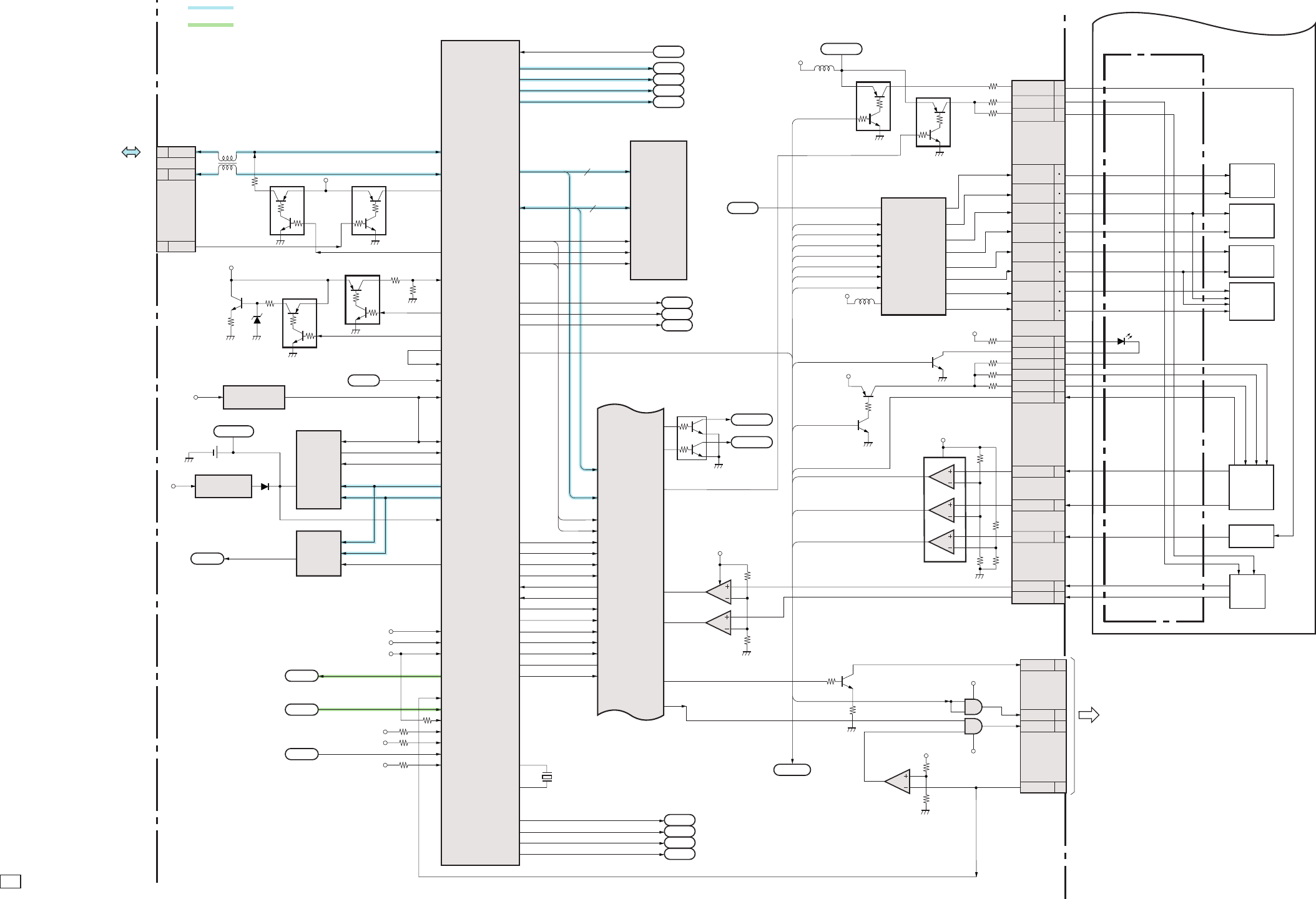
C CANON INC., 2002
01 OCTOBER, 2002
2.3 MAIN PCB ASS’Y (2/3)
MAIN PCB ASS’Y (2/3) OPT FPC
OPTICAL UNIT 2/2
20
CPU_A_1-20
CPU_A_16-19
16
A0
ı
A19
DQ0
ı
DQ15
CPUAD_0
ı
CPUAD_15
CPUADR_0
ı
CPUADR_3
A1
ı
A20
D0
ı
D15
EX2
ı
EX63
DATA COMMUNICATION
ANALOG AUDIO SIGNAL
13
14
5
15
30
16
8
CN1501 2/2
10
9
D+
6VBUS
D–
CN1004 2/2
15
14
12
13
LED_BL
STSP
EX38
EX37
EX36
EX35
EX38
EX37
EX36
EX35
EX13
EX12
EX11
EX13
EX12
EX11
EX10
EX9
EX1
EX0
EX3
EX10
EX9
EX1
EX0
EX3
EXPORT
EFCHG
VCHGLVL
AFLEDAN
AFLEDK
ZMPI_AN
ZMPI_AN
ZMPI_AN
ZM_RST
SLNT_DET1
AF Support,
SELF,Red Eye
EVR_1
AIN6
ADIN2
EVR_1
INTP2
BUT_BATT
DAOUT
2
1
5
4
7
6
8
Zoom
Motor
AF
Motor
IRIS
Motor
SHUTTER
Motor
AF PI
SLANT PI
Zoom PI
IN1
IN2
INB
INA
MD1
VDC
MD2
MD3
Q1902
SWITCH
2SA1774
Q1901
SWITCH
2SC4617
Q1010
LED Drive
2PC4617
Q1007
LED Drive
XP6213
To FLASH/DC UNIT
EX59
EX62
EX56
EX55
EX54
EX57
EX15
VZMCNT
EX58
EX63
33
IC1013
AND GATE
TC7SET08FU
IC1903
AND GATE
SN74AHC1G08HDCK
1
24
1
24
VCC1A_3
9
8
14
IC1901 2/2
Comparator
NJM12901V
IC1015
Comparator
NJM12903R
3
2
1
VCC1
EFCHGC
IC1005
FLASH PROM
MBM29LV1608E90PBT-J
TG_HD
SCLK3
SCLK2
SDATA3
SDATA2
/WE
/CE
/OE
/WE
/OE
TG_CS
AD_LD
LCD_CS
4
31
37
IC1011 (2/3)
Digital Signal Processing IC
T8F80XB-0001
6
1
4
2
5
3
P3_2
P3_3
P3_4
P3_1
/WE
/OE CPURDWR
CPUMEMIO
TRST
TMS
TCK
TDI
INTRINTP1
NWAITWAITB
NCSE
UBEB
ALE
ESREQ
ESDT
TRST
TMS
TCK
TDO
UBEB
ALE
ESREQ
ESDT
BUSCLK
NRESET
CSENGB
EX42
ECLK
MRDB
MRWB
CSMEMB
IC1001 CPU
µPD82518F1-021-EN6
D_P
D_N
USB_VBUS
EX41
EX39
EX40
EX6
EX7
EX8
EX4
EX5
AIN_0
INTP0
INTP2
RESETB
CS2
32KIN
LIVDD
VDD 1-22
AVDD
AVREF
AOUT
AIN 1
AIN 2
AIN 4
AIN 3
AIN 5
AIN 6
AIN 7
E1LAT
E2LAT
E21LAT
E3LAT
X1001
24MHz
OSC_X1
OSC_X2
VCC1.CF
VCC2_AD
VDD 3
VBATTMP
AUDIO_REC
AUDIO_PB
VCC 1
VCC 1A
VCC 1A_3
VCHGLVL
7
8
2
3
6
7
6
8
2
1
A02
CLK
CLK
DI
LD
IC1004 EVR
BH2220FVM
32
VBATT
IC1008
BAT1001
IC1002
+3.3V REG
S-817A33ANB VDD
CE1
CE0
FOUT
DATA
1
2
VCC1 RESET
S-80927ANMP
IC1007 Real Time Clock
RTC-4574JE
TOUT3
CF_IREQ
Q1001
XPO3311
Q1003 SWITCH
XPO3311
Q1009
SWITCH
XPO3311
Q1008
SWITCH
XPO3311
2.0B
10
Q10002
2SD1664
VBATT BATTERY LOAD
TEST
43
2
2
2
43
43
2
34
VCC1
L1504
11
1
1
VCC2RE
VCC1
LED_ORANGE
LED_MACRO
USB
CPU_RST
VZMCNT
5
6
7
2
SLNT_DET0
P4U_1
P4U_2
11
10
VCC1_ML
13
IC1901
Compatator
NJM12901V
EX14
VCC1_ML
EX46
ZMPO1
ZMPO0
AFRSTC
EX60
Q1903
LED Drive
2SC4617
31
ZMPO_1
6
ZMPO_0
33
AFRST
VBATT
OUTB
OUT2
OUT6
OUT3
OUT5
OUTA
OUT4
OUT1 28
27
AFA-
26
25
AFB+
24
23
IR+, AFB-
22
21
IR-
20
19
SH-
18
17
SH+, AFA+
12
11
ZMO-
10
9
ZMO+
Q1902
Motor Drive
LB8648T
9
10
11
12
13
14
15
6
22
26
27
19
20
21
25
24
VCC2RE
Q1905
SWITCH
XPO3311
Q1904
SWITCH
XPO3311
32
1
7
AFPI_AN
CN1901
SLNT_AN
SLNT_AN
P3_7
VCC1_ML
VCC1
C CANON INC., 2002
01 OCTOBER, 2002
2.4 MAIN PCB ASS’Y (3/3)
MAIN PCB ASS’Y (3/3)
16
6
17
13
12
14
18
19
10
CN1003
VCC1
LED_GREEN
LED_ORANGE
LED_MACRO
POWER
SW1
SW2
TELE
IC1012
16M SDRAM
K4S283233F-MN1L
IC1011 (3/3)
Digital Signal Processing IC
T8F80XB-0001
POWER
LED_ORANGE
LED_MACRO
VCC1_CF
INT P 2
12
3
8
16
32
2
4
A0
ı
A11 P1_0
ı
P1_7
PCADR_0
ı
PCADR_2
SDADR_0
ı
SDADR_11
SDDT_0
ı
SDDT_31
SDDQM_0
ı
SDDQM_3 PCDT_0
ı
PCDT_15
DQ0
ı
DQ31
DQM0
ı
DQM3
X1002
27MHz
CN602
DATA COMMUNICATION
16
8
11
3
16
38
13
25
26
40
33
44
41
36
37
42
7
32
35
34
27
ı
31
47
ı
49
2
ı
6
21
ı
23
8
12
ı
10
20
ı
14
24
9
To
FLASH/DC UNIT
CF Card
A00
D00
D15
/IORD
/IOWR
VCC
/CD2
/VS2
/VS1
/OE
/REG
/WE
/WAIT
/CE2
/CE1
IREQ
/IOIS16
RESET
/CD1
A10
CN1005
14
13
49
27
18
4
38
20
10
12
22
1
2
8
6
39
25
23
21
19
17
15
11
9
7
3
41
43
45
28
30
32
34
36
44
46
48
29
31
33
35
37
47
5
A10
A00
A02
A03
D00
D15
/IORD
/IOWR
VCC1
/CD2
/VS2
/VS1
/OE
/REG
/WE
/WAIT
/CE2
/CE1
IREQ
/IOIS16
RESET
/CD1
CN601
14
13
49
27
18
4
38
20
10
12
22
1
2
8
6
39
25
23
21
19
17
15
11
9
7
3
41
43
45
28
30
32
34
36
44
46
48
29
31
33
35
37
47
5
WIDE
MODE1
SCAN
CFOP
15
2
3
4
5
VBATTEP AIN6
BUZZER
16
6
17
13
12
14
18
19
10
CN401
VCC1
LED_GREEN
LED_ORANGE
LED_MACRO
VCC1
VCC1SO
VCC1
VDD1-4
VDDQ1-10
POWER
SW1
SW401
SW404
SW501
SW502
SW503
SW504
SW505
SW506
SW402
SW403
SW2
TELE
WIDE
TELE
WIDE
MODE1
SCAN
CFOP
POWER
Release SW2
Release SW1
CFOPEN
15
2
3
4
5
BVATTEP
BUZZER
3
4
2
7
8
9
CN1002
BTOP
10
UP
LEFT
DOWN
RIGHT
EXP/WB/ERASE
DISP
15
3
4
2
5,6
1,2
OPERATION KEY UNIT
CF UNIT
RLS FPC
BATTERY BOX
Buzzer
BAT401
Button BATTERY
FU401
(OPR FPC)
BATTERY
Open Detect
UP Button
EXP/WB/ERASE
LEFT Button
RIGHT Button
DOWN Button
EX28
EX29
EX30
EX31
4
3
6
1
5
Q1018
2PC4617
Q1016-Q1018 : CF POWER CONT
Q1015
CF POWER SW
uPA1912TE
Q1020 (2/2)
LED DRIVE
XP6213
Q1005
Level Shift
XP03311
Q1017,Q1016
PDTC144EE
3
4
2
1
EX53
EX44
EX43
EX61
VCC1
EX26
EX25
EX24
EX2
EX22
EX23
EX49
EX18
EX27
EX19
EX21
EX16
EX28-31
EX20
EXPORT
BA0
BA1
SDBS_O
SDBS_1
K8
K7
J9
J8
J1
J2
/WE
/CAS
/CS
/RAS
CKE
VXIN
SDCKE
SDWE
SDCLK
SDCS_0
CLK
SDRAS
SDCAS
VXOUT
CF_A_3-10
CF_D_0-15
CF_A_0-2
NPC RD
NPC WR
PCCE1
PCRDY
PCIRQ
PCIOIS
P0-5
P0-1
P0-0
P0-4
PCCE2
LED402
LED401
REC PLAY
GREEN
ORANGE
YELLOW
Q1020 1/2
LED Drive
XP6213
Q1004
ED Drive
PDTC144EE
EX45
BATTERY BOX UNIT
11
MODE0 11 MODE0 EX48
VBATTMP
11 MENU
12 SET
1SCAN
5LED_POWERAN
6LED_POWER
EX52
EX51
EX17
SW507 DISP Button
SW508 MENU Button
SW509
LED501
POWER
SET Button
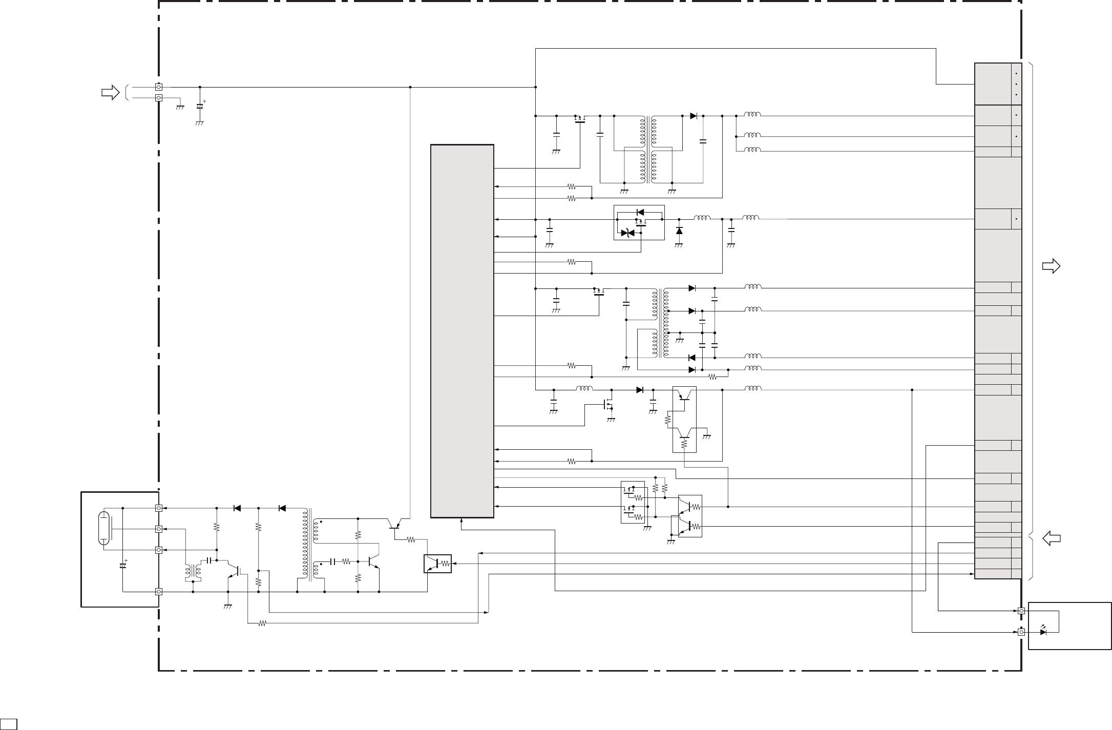
C CANON INC., 2002
01 OCTOBER, 2002
2.5 FLASH/DC UNIT
FLASH/DC UNIT
From
BATTERY BOX UNIT
CN101
To
MAIN PCB ASS’Y
VCHGLVL
LED_BL
E1P LAT
EFCHG
STSP
5
8
9
23
24
E1P LAT 4
VCC2AFE
VEE2 2
21
E3 LAT 20
E2 LAT 22
11
10
26
27
25
7
14
12
15
VBATT
19
VCC2RE
VCC1A
VCC1
VCC1SD
6
5
VCC1L
VDD2
3
VDD3
13
From
MAIN PCB ASS’Y
BACK LIGHT UNIT
FLASH
V BATT
IC101
SW REG CONTROL
MB39A102PFT
25
29
28
3
24
13
14
2
5
26
22
17
18
6
27,4,12,19
16
15
OUT1
OUT2
FB2
-INE2
-INE1
FB1
OUT3
FB3
FB4
CTL
DTC1-4
CS4
CS3
CTL
OUT4
-INE3
-INE4
VCC
VCCO
T104
Q010
XE Drive
CY20AAJ-B
Q103
EF Charge
2SB1197K
D103D105 T101
2
1
3
4
5
VCHGLVL
STSP
Q105
OSC
2SC4672
Q101 SW
DTC144EE
EFCHG
L108
L109
L110
L111
C101 D110
D107
C137
C134
C138
C142
C118
C126
C119
C120
C127
C121
C132
D104
C133,C136
C130,C131
T102
L106
L112
L113
L115
L114
L116
81
4
2
3
5
4
3
6
5
7
6
T103
1
8
2
2
3
4
61
5
4
4
2
6
1
3
5
5
1
2
6
3
7
3
45.6
Q106
PWM SWITCH
MCH3306
Q107
PWM SWITCH
SSM6J08FU
Q108
PWM SWITCH
MCH3306
Q109
PWM SWITCH
SSM6K08FU
Q102
CONTROL SWITCH
SSM6N16FE
Q104
SWITCH
XP6213
Q111
VDD3 SWITCH
UMF5N
LED-BL
VDD3
D111
D112
D106
L107
D108

2.6 Abbreviation in Block Diagrams
Abbreviation Nominal name Description
ADC Analog-to-Digital (A/D) Converter
AE Automatic Exposure control
AF Automatic Focussing control
AND Logic AND circuit
R-Y/B-Y Color difference signals of TV system
BPF Band-Pass Filter
BUFFER Buffer circuit
C Chrominance signal Color component signal of TV system
CCD Charge-Coupled Device CCD imager
CDS Correlated Double Sampling system
COMP.VIDEO Composite video signal
COMPARATOR Voltage comparator
CPU Central Processing Unit
DAC Digital-to-Analog (D/A) Converter
DRAM Dynamic Random Access Memory Memory with which read and write are freely possible.
DSP Digital Signal Processing Typically DSP device
EEPROM Electrically Erasable PROM PROM that is electrically erasable.
EVF Electronic View Finder
FET Field Effect Transistor
FLASH MEMORY Non-volatile memory with which write and read are freely
possible.
HPF High-Pass Filter
I/F InterFace The circuit that interconnects 2 devices or circuits.
IGBT Insulated Gate Bipolar Transistor Conductivity-modulation type FET transistor
INV. Logic Inverter circuit
IR InfraRed ray
IRIS Iris
LCD Liquid Crystal Device Typically LCD display
LED Light Emitting Diode Typically LED display
LPF Low-Pass Filter
NTSC National Television System Committees NTSC color TV system developed in USA
OP Amp OPerational Amplifier
OR Logic OR circuit
OSC OSCillator
PAL Phase Alternating by Line PAL color TV system developed in Germany
PLL Phase Locked Loop
PROM Programmable Read Only Memory Non-volatile memory in which program can be written.
PWM Pulse Width Modulation
REG. REGulated power supply
RTC Real Time Clock Reference clock oscillator
SDRAM Synchronous Dynamic RAM DRAM whose bus interface is synchronous.
SECAM SEquential Colour À Mémoire SECAM color TV system developed in France
SW REG SWitching REGulator Switching type regulated power supply device
TG Timing Generator
USB Universal Serial Bus USB type serial data communication system
VCO Voltage Controlled Oscillator
VCXO Voltage Controlled X’tal Oscillator
XE Xenon Tube
Y Y-signal Luminance component signal of TV system
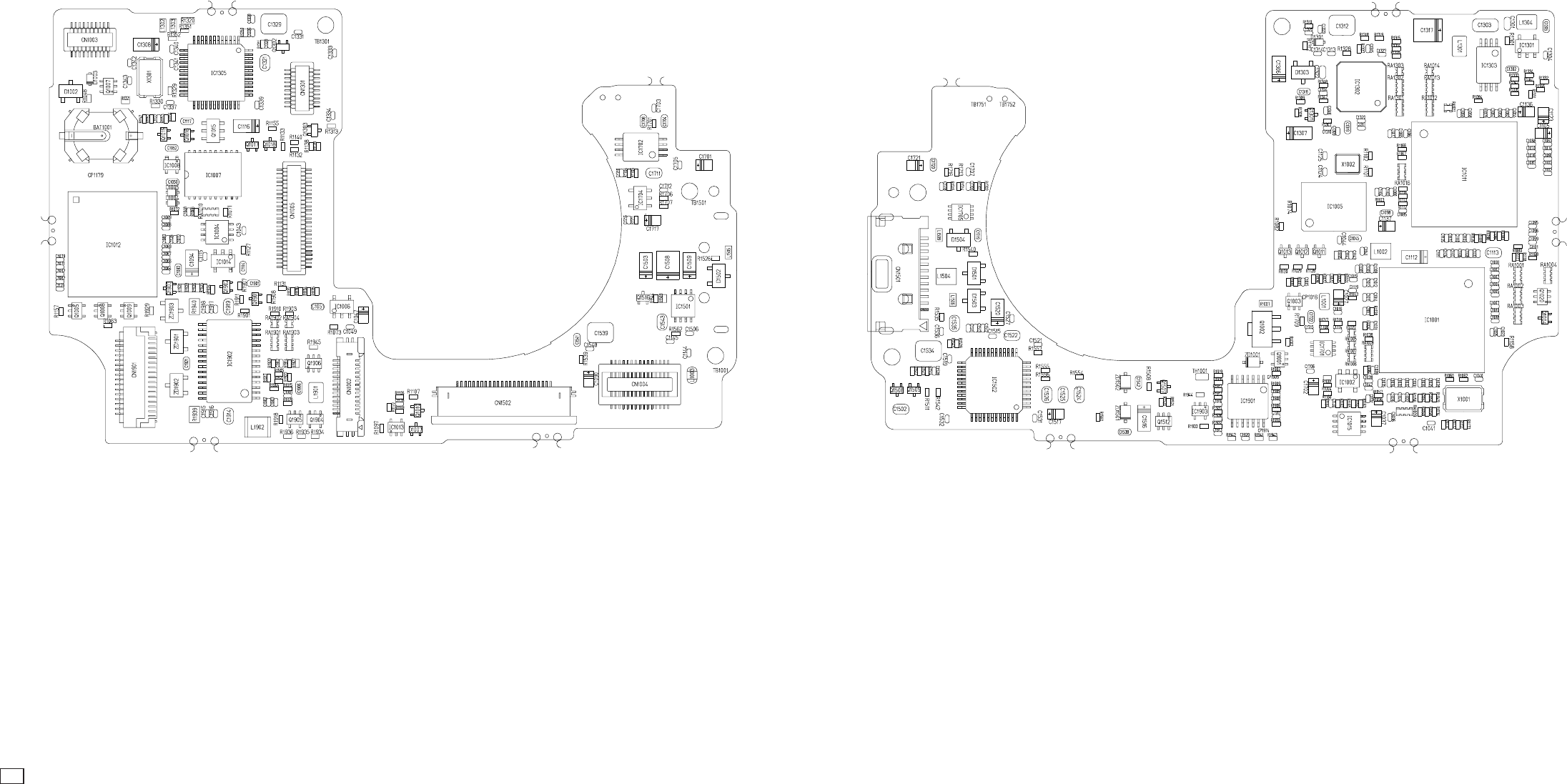
C CANON INC., 2002
01 OCTOBER, 2002
3. P.C.B. DIAGRAMS
3.1 MAIN PCB ASS’Y
MAIN PCB ASS’Y (SOLDERING SIDE) MAIN PCB ASS’Y (COMPONENT SIDE)
C CANON INC., 2002
01 OCTOBER, 2002
3.2 FLASH/DC UNIT
FLASH/DC UNIT (SOLDERING SIDE) FLASH/DC UNIT (COMPONENT SIDE)
C CANON INC., 2002
01 OCTOBER, 2002
3.3 OPTICAL UNIT
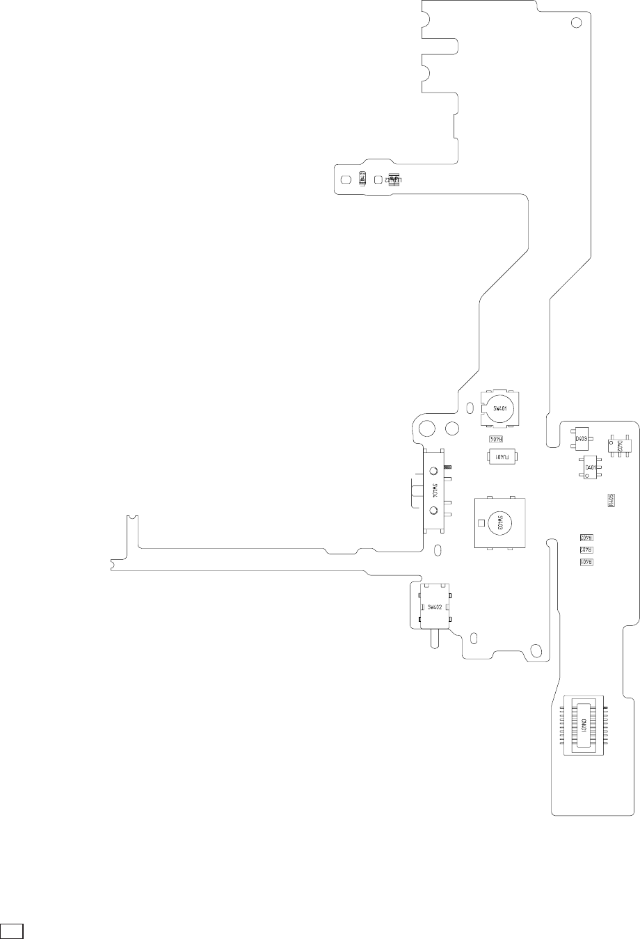
C CANON INC., 2002
01 OCTOBER, 2002
3.4 BATTERY BOX UNIT
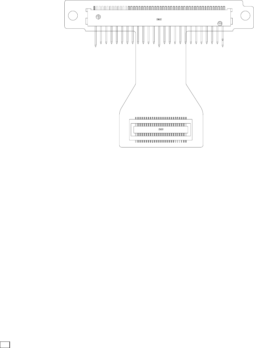
C CANON INC., 2002
01 OCTOBER, 2002
3.5 CF UNIT
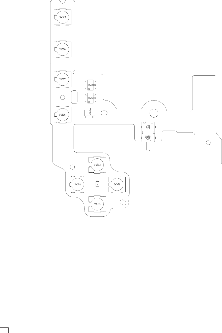
C CANON INC., 2002
01 OCTOBER, 2002
3.6 OPERATION KEY UNIT
How to print out the Zoom/AF Chart
The large materials such as “Zoom/AF Chart” that occupy a page of large size, can be divided into
several smaller pages using “Graphic Select Tool” for printing the entire page.
< Procedures >
1. Select “ Text Select Tool” from the Command Bar and keep pressing it.
Then, select the “ Graphic Select Tool”.
2. Select the desired portion to print. (Drag the cursor on desired area.)
3. Click “Print” of the Menu Bar. Check “Selected Thumbnails/Graphic”, then start printing.
When you check “Fit to Page”, the date can be reduced or enlarged of its printing size so that the
printing size fits the size of paper.*
4. To cancel the printing area, click an arbitrary position on the display.
*Remarks
The “Zoom/AF Chart” of the Service Manual that is saved in this CD-ROM, has the colored markings
in colors so that the entire page can be divided into print papers (legal-size x 4 pages, A3 size x 3 pages).
Operate as follows.
Select “Graphic Select Tool”. Select the 2 markings having the same color to select the first printing
area. Press “Print” to print the first printing area. Perform the above steps 2 and 3. Select another 2
markings having the second color to select the second printing area. Press “Print” to print the second
printing area. Repeat this procedure until the all pages are printed.
<Legal-size>
: Markings
<A3 size>

PowerShot S230/DIGITAL IXUS v
3
/
IXY DIGITAL 320 Zoom/AF Chart
✂
PowerShot S230/DIGITAL IXUS v3/IXY DIGITAL 320 Zoom/AF Chart
Dimensions
519.94mm
131.53mm 412.91mm
311.99mm
157.48mm
157.52mm
65.90mm
262.53mm
209.54mm
196.90mm
389.95mm
