Canon Security Camera Vk 16 Users Manual Network Video Recorder 64/VK User's
Canon Network Video Recorder VK-64 - VK-16 User Manual Canon Network Video Recorder VK-64 - VK-16 User Manual
VK-16 to the manual d7e02bc6-f1d2-44fb-b062-961a95e0e919
2015-01-23
: Canon Canon-Security-Camera-Vk-16-Users-Manual-242633 canon-security-camera-vk-16-users-manual-242633 canon pdf
Open the PDF directly: View PDF ![]() .
.
Page Count: 156 [warning: Documents this large are best viewed by clicking the View PDF Link!]

509-0162 CANONsama NETWORK VIDEO RECORDER VK-64/VK-16 USER’S MANUAL hyo1-4
Network Video Recorder
VK-64/VK-16 v1.1 User
’s Manual
User’s Manual
Ver. 1.1
Network Camera Recording and Monitoring System
Network Video Recorder
VK-64/ VK-16 v1.1
Storage Server & Viewer
CANON INC. 30-2, Shimomaruko 3-chome, Ohta-ku, Tokyo 146-8501, Japan
U.S.A. CANON U.S.A.,INC. NEW JERSEY OFFICE
100 Jamesburg Road, Jamesburg, NJ 08831 USA
CANON U.S.A.,INC. CHICAGO OFFICE
100 Park Blvd., Itasca, IL 60143 USA
CANON U.S.A.,INC. LOS ANGELES OFFICE
15955 Alton Parkway, Irvine, CA 92618 USA
CANON U.S.A.,INC. HONOLULU OFFICE
210 Ward Avenue, Suite 200 Honolulu, HI 96814 USA
zIf you have any questions, call the Canon U.S.A. Information
Center toll-free at 1-800-828-4040(U.S.A.only)
CANADA CANON CANADA INC.NATIONAL HEADQUARTERS
6390 Dixie Road, Mississauga, Ontario L5T 1P7
CANON CANADA INC. CALGARY
2828, 16th Street, N.E, Calgary, Alberta T2E 7K7
CANON CANADA INC. MONTRÉAL
5990 Côte-de-Liesse, Montréal, Québec H4T 1V7
zIf you have any questions, call the CANON CANADA Customer Information
Centre toll-free at 1-800-OK-CANON (652-2666) (Canada only)
MEXICO CANON MEXICANA, S DE R.L.DE C.V.
Boulevard Manuel Avila Camacho, No.138 PB, Pisos 15, 16 y 17 Col Lomas de
Chapultepec C.P. 11000 México, D.F. México
CENTRO Y
SURAMERICA CANON LATIN AMERICA, INC.
703 Waterford Way, Suite 400, Miami, FL33126, USA
ASIA CANON SINGAPORE PTE LTD
1 HarbourFront Avenue, #04-01, Keppel Bay Tower
Singapore 098632
CANON HONGKONG CO., LTD.
19/F., The Metropolis Tower, 10 Metropolis Drive, Hunghom, Kowloon,
Hong Kong
OCEANIA CANON AUSTRALIA PTY. LTD.
1 Thomas Holt Drive, North Ryde, Sydney, N.S.W. 2113, Australia
EUROPE CANON EUROPA N.V.
Bovenkerkerweg 59-61, P.O. Box 2262, 1180 EG Amstelveen, The Netherlands
CANON EUROPE LTD.
6 Roundwood Avenue, Stockley Park, Uxbridge Middlesex, UB11 1JA,
United Kingdom
PUB. VK-050902 © CANON INC.2005 PRINTED IN JAPAN
Introduction
2
Thank you for purchasing Network Video Recorder VK-64 v1.1 (hereafter referred to as
‘VK-64’), a network video recording and monitoring system.
This manual describes the configuration and operation procedures for Storage Server and
Viewer. Please read this manual prior to operation to ensure you will be able to use the Viewer
and Storage Server effectively. This manual is also intended for Network Video Recorder VK-16
v1.1 (hereinafter referred to as ‘VK-16’). Please refer to page 7 for differences between VK-64
and VK-16. When you have finished reading this manual, please store it in a safe place.
Request to Customers
(1) The content of this manual may not be reproduced in its entirety or in part without
prior permission.
(2) The content of this manual is subject to change without notice.
(3) All possible measures have been taken to ensure that the content of this manual is
accurate. If you happen to notice errors, omissions or other faults, please contact
your vendor.
(4) Irrespective of items (2) and (3) above, Canon cannot bear responsibility for any
effects that result from operation.
Trademarks
Canon and the Canon logo are registered trademarks of Canon Inc.
Microsoft Windows is a trademark of Microsoft Corporation in the United States and other countries.
QuickTime is a trademark of Apple Computer Inc.
Apache is a trademark of the Apache Software Foundation.
Windows is legally recognized as Microsoft Windows Operating System.
Pentium is a trademark of Intel Corporation.
All other company or product names used in this manual are trademarks or registered trademarks of
their respective holders.
Copyright Information
Please note that copyright laws prohibit the customer from using recorded videos and still pictures for any
purpose other than personal requirements, without permission from the copyright holder.
Support Information
For various types of information relating to support, including updated product software (patch installer),
User’s Manual, operating environment, etc., please refer to our WebView Product web page:
http://www.canon.com/webview
Icons Used in this Manual
Indicates important information that must be observed or actions that are
prohibited during an operation. These notes must be read to prevent possible
faults or errors during operation.
Indicates supplementary information or a reference to an operation. Users are
advised to read these memos.
Note
Tip
Document No. 3743 Version 1.0, 030904.
Storage Server includes software developed by the Apache Software Foundation (www.apache.org). The Apache software is Copyright (c) 2000-2003
The Apache Software Foundation. All rights reserved. For the license terms associated with this software, please refer to the file APACHE_LICENSE in
the folder LICENSE, within the installation directory.
VK-16 has the same functionality as VK-64 outlined in this manual,
unless explicitly indicated otherwise.
Note

3
Introduction . . . . . . . . . . . . . . . . . . . . . . . . . . . . . . . . . . . . . . . . . . . . . . . . . . . . . .2
Overview . . . . . . . . . . . . . . . . . . . . . . . . . . . . . . . . . . . . . . . . . . . . . . . . . . . . . . . .7
System Configuration . . . . . . . . . . . . . . . . . . . . . . . . . . . . . . . . . . . . . . . . . . . . . .8
Typical System Configuration . . . . . . . . . . . . . . . . . . . . . . . . . . . . . . . . . . . .8
Overview of Setup . . . . . . . . . . . . . . . . . . . . . . . . . . . . . . . . . . . . . . . . . . . . . . . .10
Supported Camera Servers . . . . . . . . . . . . . . . . . . . . . . . . . . . . . . . . . . . . . . . . .12
Canon Camera Servers . . . . . . . . . . . . . . . . . . . . . . . . . . . . . . . . . . . . . . . .12
Firmware Upgrade . . . . . . . . . . . . . . . . . . . . . . . . . . . . . . . . . . . . . . . . . . .12
Operating Environment . . . . . . . . . . . . . . . . . . . . . . . . . . . . . . . . . . . . . . . . . . . .13
Viewer System Requirements . . . . . . . . . . . . . . . . . . . . . . . . . . . . . . . . . . .13
Storage Server System Requirements . . . . . . . . . . . . . . . . . . . . . . . . . . . . .13
Using the Storage Server with Windows XP SP2 . . . . . . . . . . . . . . . . . . . . .14
PART 1: INSTALLATION & CONFIGURATION
Chapter 1 Installation
Before you begin installation... . . . . . . . . . . . . . . . . . . . . . . . . . . . . . . . . . . . . . .16
Suggested Network Configurations . . . . . . . . . . . . . . . . . . . . . . . . . . . . . . .16
Setting up the Camera Servers . . . . . . . . . . . . . . . . . . . . . . . . . . . . . . . . . .18
About the Master Storage Server . . . . . . . . . . . . . . . . . . . . . . . . . . . . . . . . .18
When using multiple Storage Servers... . . . . . . . . . . . . . . . . . . . . . . . . . . . .18
Installation Procedures . . . . . . . . . . . . . . . . . . . . . . . . . . . . . . . . . . . . . . . . . . . .19
Starting up the Installer . . . . . . . . . . . . . . . . . . . . . . . . . . . . . . . . . . . . . . . .19
Upgrading from Version 1.0 . . . . . . . . . . . . . . . . . . . . . . . . . . . . . . . . . . . . .20
Chapter 2 Configuring the Storage Server
Storage Server Configuration . . . . . . . . . . . . . . . . . . . . . . . . . . . . . . . . . . . . . . .22
Launching Procedure . . . . . . . . . . . . . . . . . . . . . . . . . . . . . . . . . . . . . . . . .22
Adjusting the Storage Server Settings . . . . . . . . . . . . . . . . . . . . . . . . . . . . .22
How the Storage Server manages disk space . . . . . . . . . . . . . . . . . . . . . . .24
Setting up Event Notifications . . . . . . . . . . . . . . . . . . . . . . . . . . . . . . . . . . . . . . .25
Set up a user to receive Event Notification emails . . . . . . . . . . . . . . . . . . . .25
Setting up Users . . . . . . . . . . . . . . . . . . . . . . . . . . . . . . . . . . . . . . . . . . . . . . . . .26
Adding and Editing Users . . . . . . . . . . . . . . . . . . . . . . . . . . . . . . . . . . . . . .26
User Management tab - Add Users . . . . . . . . . . . . . . . . . . . . . . . . . . . . . . .27
User Management tab - Edit Users . . . . . . . . . . . . . . . . . . . . . . . . . . . . . . .28
User Management tab - Remove Users . . . . . . . . . . . . . . . . . . . . . . . . . . . .28
Chapter 3 Starting the Viewer
Starting the Viewer . . . . . . . . . . . . . . . . . . . . . . . . . . . . . . . . . . . . . . . . . . . . . . . .30
Launching Procedure . . . . . . . . . . . . . . . . . . . . . . . . . . . . . . . . . . . . . . . . .30
Changing the Storage Server . . . . . . . . . . . . . . . . . . . . . . . . . . . . . . . . . . . . . . .31
Setting the Master Storage Server . . . . . . . . . . . . . . . . . . . . . . . . . . . . . . . .31
Contents

4
Chapter 4 System Configuration, Before You Begin
After the Viewer has launched... . . . . . . . . . . . . . . . . . . . . . . . . . . . . . . . . . . . . .34
Accessing the Configuration and Preferences screen . . . . . . . . . . . . . . . . .35
System Configuration Process . . . . . . . . . . . . . . . . . . . . . . . . . . . . . . . . . . . . . .36
Configuration and Preferences screen . . . . . . . . . . . . . . . . . . . . . . . . . . . . . . . .38
About the Configuration and Preferences screen . . . . . . . . . . . . . . . . . . . . .38
Selecting a Configuration and Preferences window . . . . . . . . . . . . . . . . . . .38
Chapter 5 Register Storage Servers and Camera Servers
Camera Summary Window . . . . . . . . . . . . . . . . . . . . . . . . . . . . . . . . . . . . . . . . .42
About the Storage and Camera Server Summary Window . . . . . . . . . . . . . .42
Storage Server and Location / Zone options . . . . . . . . . . . . . . . . . . . . . . . .43
Other functions in both sub-windows . . . . . . . . . . . . . . . . . . . . . . . . . . . . . .43
Locations and Zones . . . . . . . . . . . . . . . . . . . . . . . . . . . . . . . . . . . . . . . . . . . . . .44
About Locations and Zones . . . . . . . . . . . . . . . . . . . . . . . . . . . . . . . . . . . . .44
Configure Camera Summaries . . . . . . . . . . . . . . . . . . . . . . . . . . . . . . . . . . . . . .46
Camera Summary - Add, Edit and Delete a Storage Server . . . . . . . . . . . . .46
Camera Summary - Add, Edit or Delete a Location/Zone . . . . . . . . . . . . . . .47
Camera Summary - Find Camera Servers . . . . . . . . . . . . . . . . . . . . . . . . . .49
Using the Add Camera Server Dialog . . . . . . . . . . . . . . . . . . . . . . . . . . . . . . . . .51
About the Add Camera Server Dialog . . . . . . . . . . . . . . . . . . . . . . . . . . . . .51
Set up camera position and saved video . . . . . . . . . . . . . . . . . . . . . . . . . . .52
Add a Camera Server - Set connection details . . . . . . . . . . . . . . . . . . . . . .53
Camera Summary - Edit Camera Server Settings . . . . . . . . . . . . . . . . . . . .55
Edit and Remove Camera Servers . . . . . . . . . . . . . . . . . . . . . . . . . . . . . . . . . . .57
Camera Summary - Edit Camera Server . . . . . . . . . . . . . . . . . . . . . . . . . . .57
Camera Summary - Remove Camera Server . . . . . . . . . . . . . . . . . . . . . . .58
Saving Configuration Changes . . . . . . . . . . . . . . . . . . . . . . . . . . . . . . . . . . . . . .59
Camera Summary - When you have finished configuration . . . . . . . . . . . . .59
Chapter 6 Configuring Recording Schedules
Configure Normal Recording . . . . . . . . . . . . . . . . . . . . . . . . . . . . . . . . . . . . . . . .62
About the Recording Schedules window - Normal Recording . . . . . . . . . . . .62
Create, Edit and Delete Recording Schedule Items . . . . . . . . . . . . . . . . . . .64
Add/Edit Schedule Item dialog - Schedule field . . . . . . . . . . . . . . . . . . . . . .66
Add/Edit Schedule Item dialog - Recording Settings field . . . . . . . . . . . . . . .67
Configure Motion and Sensor Settings . . . . . . . . . . . . . . . . . . . . . . . . . . . . . . . .70
Recording Schedule dialog - Motion and Sensor Settings . . . . . . . . . . . . . .70
Recording Schedule - Edit Motion Detection Settings . . . . . . . . . . . . . . . . .71
About motion detection on different camera servers . . . . . . . . . . . . . . . . . . .75
Recording Schedule - Edit Sensor Events Settings . . . . . . . . . . . . . . . . . . .76
Saving Normal Recording Changes . . . . . . . . . . . . . . . . . . . . . . . . . . . . . . . . . .79
When you have finished Normal Recording configuration... . . . . . . . . . . . . .79
Configure Special Day Recording . . . . . . . . . . . . . . . . . . . . . . . . . . . . . . . . . . . .80
Contents

5
About Special Day Recording . . . . . . . . . . . . . . . . . . . . . . . . . . . . . . . . . . .80
Add and Edit a Schedule Type . . . . . . . . . . . . . . . . . . . . . . . . . . . . . . . . . .82
Delete a Schedule Type . . . . . . . . . . . . . . . . . . . . . . . . . . . . . . . . . . . . . . .83
Add a Day . . . . . . . . . . . . . . . . . . . . . . . . . . . . . . . . . . . . . . . . . . . . . . . . . .84
Delete a Day . . . . . . . . . . . . . . . . . . . . . . . . . . . . . . . . . . . . . . . . . . . . . . . .85
Saving Special Day Changes . . . . . . . . . . . . . . . . . . . . . . . . . . . . . . . . . . . . . . . .86
When you have finished Special Day configuration... . . . . . . . . . . . . . . . . . .86
Chapter 7 Configuring Viewer Settings
Configure Viewer Settings . . . . . . . . . . . . . . . . . . . . . . . . . . . . . . . . . . . . . . . . . .88
About the Viewer Settings window . . . . . . . . . . . . . . . . . . . . . . . . . . . . . . . .88
Viewer Settings window - Use large captions for Video Windows . . . . . . . . .90
Viewer Settings window - Identify the Master Storage Server . . . . . . . . . . . .90
Viewer Settings window - Edit Event Notifications . . . . . . . . . . . . . . . . . . . .91
Saving Viewer Settings . . . . . . . . . . . . . . . . . . . . . . . . . . . . . . . . . . . . . . . . . . . .92
When you have finished configuring Viewer settings... . . . . . . . . . . . . . . . . .92
PART 2: USING THE VIEWER APPLICATION
Chapter 8 Using the Viewer - Operator Login
Viewing Screen Example . . . . . . . . . . . . . . . . . . . . . . . . . . . . . . . . . . . . . . . . . . .94
Starting the Viewing Screen . . . . . . . . . . . . . . . . . . . . . . . . . . . . . . . . . . . . . . . .96
Launching Procedure . . . . . . . . . . . . . . . . . . . . . . . . . . . . . . . . . . . . . . . . .96
Viewing Screen Menu bar . . . . . . . . . . . . . . . . . . . . . . . . . . . . . . . . . . . . . . . . . .98
Menu Bar Functions . . . . . . . . . . . . . . . . . . . . . . . . . . . . . . . . . . . . . . . . . .98
Chapter 9 Working with Video Windows
Selecting Cameras for Viewing . . . . . . . . . . . . . . . . . . . . . . . . . . . . . . . . . . . . .100
About the Camera Selection Area . . . . . . . . . . . . . . . . . . . . . . . . . . . . . . .100
About Camera Thumbnails . . . . . . . . . . . . . . . . . . . . . . . . . . . . . . . . . . . .100
Selecting Locations and their Zones . . . . . . . . . . . . . . . . . . . . . . . . . . . . .101
Basic Video Window Functions . . . . . . . . . . . . . . . . . . . . . . . . . . . . . . . . . . . . .102
Creating, scaling and moving Video Windows . . . . . . . . . . . . . . . . . . . . . .102
Selecting Multiple Video Windows . . . . . . . . . . . . . . . . . . . . . . . . . . . . . . .105
Video Window States . . . . . . . . . . . . . . . . . . . . . . . . . . . . . . . . . . . . . . . . . . . . .106
About Video Window states . . . . . . . . . . . . . . . . . . . . . . . . . . . . . . . . . . . .106
Adjust Pan, Tilt and Zoom . . . . . . . . . . . . . . . . . . . . . . . . . . . . . . . . . . . . . . . . .108
Viewing Live Video - Adjusting Pan, Tilt and Zoom . . . . . . . . . . . . . . . . . . .108
Other Video Window Functions . . . . . . . . . . . . . . . . . . . . . . . . . . . . . . . . . . . . .110
Change the size of a Video Window . . . . . . . . . . . . . . . . . . . . . . . . . . . . .110
Enable Backlight Compensation . . . . . . . . . . . . . . . . . . . . . . . . . . . . . . . .110
User-initiated Recording . . . . . . . . . . . . . . . . . . . . . . . . . . . . . . . . . . . . . . .111
Other Menu Options . . . . . . . . . . . . . . . . . . . . . . . . . . . . . . . . . . . . . . . . .111
About Shade Correction . . . . . . . . . . . . . . . . . . . . . . . . . . . . . . . . . . . . . .112
Contents

Chapter 10 Arranging and Saving Video Window Layouts
Managing Video Layouts . . . . . . . . . . . . . . . . . . . . . . . . . . . . . . . . . . . . . . . . . .114
About the Layout menu . . . . . . . . . . . . . . . . . . . . . . . . . . . . . . . . . . . . . . .114
Organizing Layouts and Layout Sequences . . . . . . . . . . . . . . . . . . . . . . . .115
Saving a Layout or Layout Sequence . . . . . . . . . . . . . . . . . . . . . . . . . . . .117
Arranging Layout Sequences . . . . . . . . . . . . . . . . . . . . . . . . . . . . . . . . . . .118
Working with Layout Grids . . . . . . . . . . . . . . . . . . . . . . . . . . . . . . . . . . . . . . . .119
Working with the Alignment Grid . . . . . . . . . . . . . . . . . . . . . . . . . . . . . . . .119
Working with Small, Medium and Large Grids . . . . . . . . . . . . . . . . . . . . . .120
Working with the Custom Grid . . . . . . . . . . . . . . . . . . . . . . . . . . . . . . . . . .123
Removing a Layout Grid . . . . . . . . . . . . . . . . . . . . . . . . . . . . . . . . . . . . . .123
Hiding and Showing Task Areas . . . . . . . . . . . . . . . . . . . . . . . . . . . . . . . . . . . .124
Using the View menu to hide and show Task Areas . . . . . . . . . . . . . . . . . .124
Chapter 11 Using the Timeline and Viewing Events
Using the Timeline . . . . . . . . . . . . . . . . . . . . . . . . . . . . . . . . . . . . . . . . . . . . . . .126
Timeline Overview . . . . . . . . . . . . . . . . . . . . . . . . . . . . . . . . . . . . . . . . . . .126
Monitoring Live Video in relation to the Timeline . . . . . . . . . . . . . . . . . . . .127
Using the Timeline to examine, play and extract video . . . . . . . . . . . . . . . .128
Daylight Savings Indicator . . . . . . . . . . . . . . . . . . . . . . . . . . . . . . . . . . . . .130
Extracting video to save to another location . . . . . . . . . . . . . . . . . . . . . . . .131
Viewing and Searching Events . . . . . . . . . . . . . . . . . . . . . . . . . . . . . . . . . . . . .132
About Live Events . . . . . . . . . . . . . . . . . . . . . . . . . . . . . . . . . . . . . . . . . . .132
Display the Live Events Log (if not displayed) . . . . . . . . . . . . . . . . . . . . . .133
Overview of Alert Parameters . . . . . . . . . . . . . . . . . . . . . . . . . . . . . . . . . .133
Searching Events . . . . . . . . . . . . . . . . . . . . . . . . . . . . . . . . . . . . . . . . . . .134
Selecting Criteria for Searching . . . . . . . . . . . . . . . . . . . . . . . . . . . . . . . . .135
Viewing found events . . . . . . . . . . . . . . . . . . . . . . . . . . . . . . . . . . . . . . . .136
Appendix A Troubleshooting VK-64
Troubleshooting VK-64 . . . . . . . . . . . . . . . . . . . . . . . . . . . . . . . . . . . . . . . . . . .138
Appendix B Example Operating Conditions
Example Operating Conditions . . . . . . . . . . . . . . . . . . . . . . . . . . . . . . . . . . . . .144
Frame sizes . . . . . . . . . . . . . . . . . . . . . . . . . . . . . . . . . . . . . . . . . . . . . . .144
Bandwidth and Disk Space . . . . . . . . . . . . . . . . . . . . . . . . . . . . . . . . . . . .145
Disk Space Management . . . . . . . . . . . . . . . . . . . . . . . . . . . . . . . . . . . . . .146
Storage Server Performance . . . . . . . . . . . . . . . . . . . . . . . . . . . . . . . . . . .148
VK-64 File Locations . . . . . . . . . . . . . . . . . . . . . . . . . . . . . . . . . . . . . . . . .150
Index
Index . . . . . . . . . . . . . . . . . . . . . . . . . . . . . . . . . . . . . . . . . . . . . . . . . . . . . . . . . .151
Contents
6
7
Overview
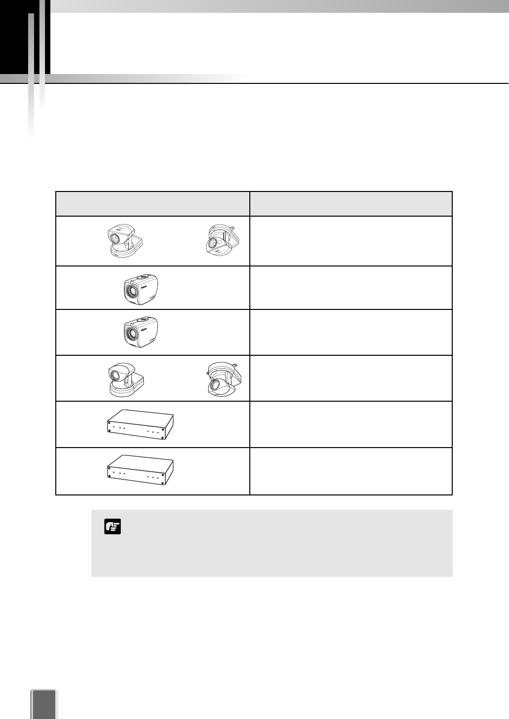
VK-64 is software that allows you to view and record images transmitted from the
Network Camera Server VB150/VB101 and Network Camera VB-C50i/VB-C50iR/
VB-C50FSi/VB-C50Fi/VB-C10/VB-C10R (hereafter referred to as ‘Camera Servers’).
The software can support up to 64 cameras via an IP network such as a LAN, or up
to 16 cameras for Network Video Recorder VK-16 v1.1.
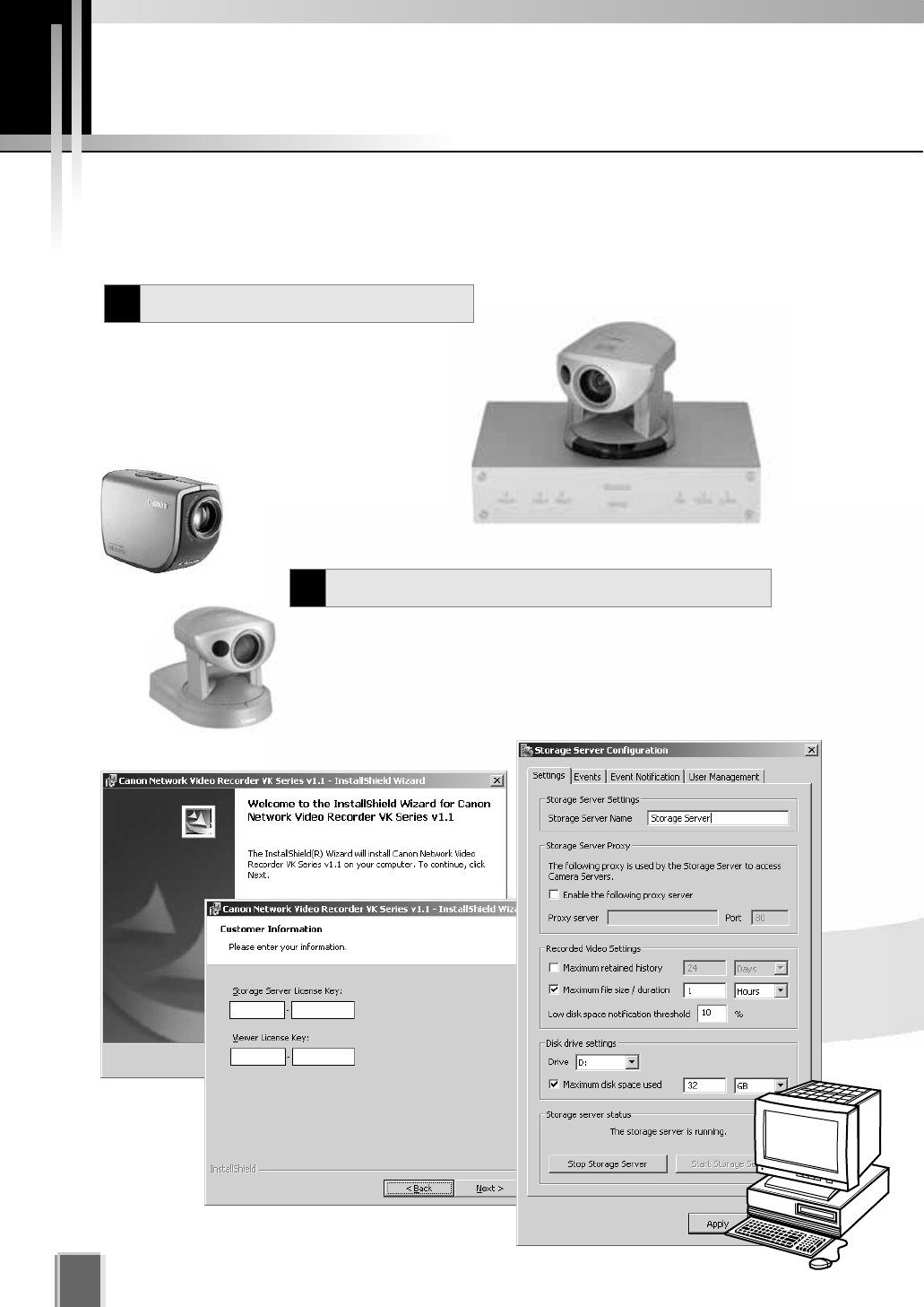
VK-64 consists of two applications: Storage Server that lets you record video from
multiple camera servers and save event information (sensor and motion-detection
inputs); and Viewer that lets you view live video from multiple Camera Servers and
playback recorded video stored on Storage Servers.
Video resolution can be as high as 640 x 480 pixels, 30 fps for NTSC and 768 x 576
pixels, 25fps for PAL (depending on Camera Servers installed).
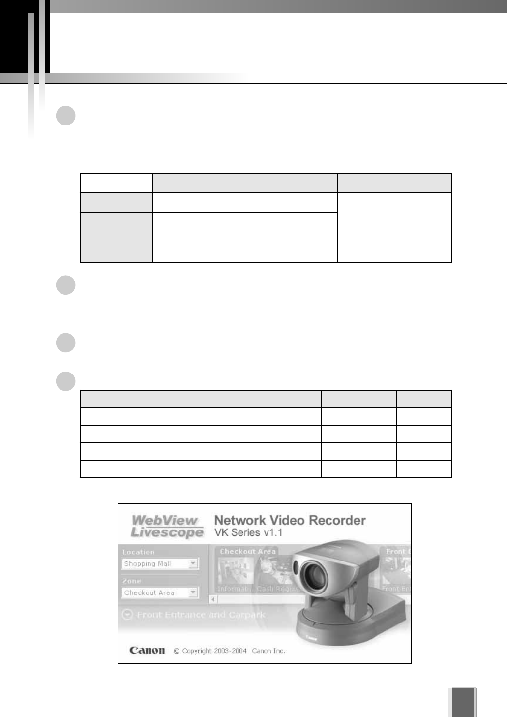
The following table shows each product and license number:
The VK-16 Viewer is identical to the VK-64 Viewer.
Storage Server Viewer
VK-64 Up to 64 cameras can be registered
VK-16
Up to 16 cameras can be registered
Functionality is the same as for VK-64
except for the above camera limitation.
Common
Product Name Storage Server Viewer
Network Video Recorder VK-64 v1.1 1 license 1 license
Network Video Recorder VK-16 v1.1 1 license 1 license
Network Video Recorder VK-64 v1.1 Viewer License _1 license
Network Video Recorder VK-64 v1.1 Viewer 5 Licenses _5 licenses
System Configuration
8
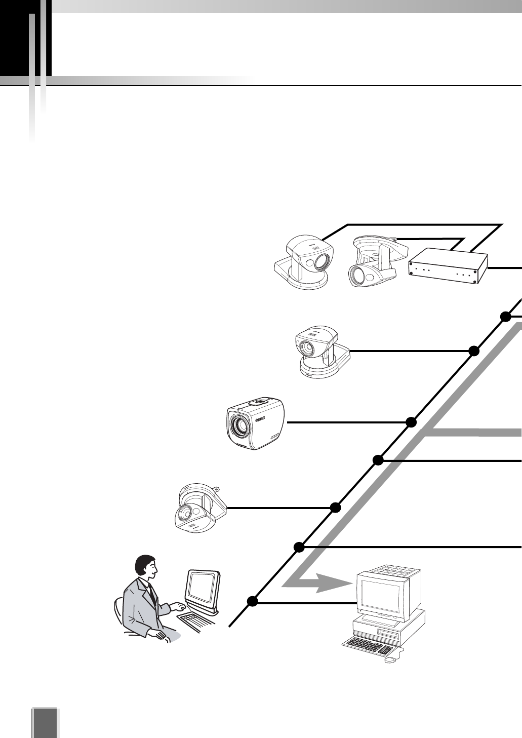
Typical System Configuration
VK-64 provides video viewing and recording from Camera Servers via an IP network such
as a LAN. Since VK-64 makes use of IP networks, installations of cameras can be
performed easily. In addition, it is possible to flexibly install new cameras and change
installation locations of cameras.
VB-C50iR
VC-C50i VC-C50iR VB150/VB101
VB-C50i
MONITOR
MONITOR
View live and recorded video
Viewer
Operator Capabilities:
View Live Video View Events View Recorded Video
PLAYBACK
PL
PLAYBACK
PLAYBACK
VB-C50FSi / VB-C50Fi
9
RECORD
RECORD
R
MONITOR
Record video to the
Storage Server # 1
Storage Server
Administrator Capabilities:
Configure Users Configure Storage Server
Configure Event Notification
Record video to the
Storage Server # 2
Storage Server
View live and recorded video
Viewer
Administrator Capabilities:
Configure recording settings Configure event alerts
Camera Server Settings Storage Server Settings
View Live Video View Events View Recorded Video
View live and recorded video
Viewer
Operator Capabilities:
View Live Video View Events
View Recorded Video
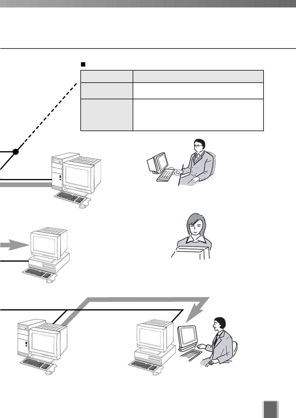
Receives and
records video. Plays back
recorded video to Viewers.
Application Function
Storage Server Stores recorded information for later retrieval and
viewing in the Viewer.
Viewer Lets users view recorded information, monitor live video
and acknowledge/search events.
Lets Administrators configure recording and viewing
settings.
Application Types and Functions
PLAYBACK
CK
PLAYBACK
BACK
Overview of Setup
10
Before you can start monitoring, recording and playing back video, you need to install and
configure the Storage Server and Viewer. The diagram below indicates the installation and
configuration process.
The first step is to set up your cameras and/or Camera
Servers. Refer to your camera and Camera Server
manuals for connection details.
Set up Network Cameras
1
Camera servers (tP. 12)
VC-C50i
VB150
Install Storage Server and Viewer
2
Install the Storage Server and Viewer on one computer or install the
Viewer on other computers on the network that will access
recorded video from the Storage Server. Configure the Storage
Server via the Storage Server Configuration utility to set server
settings, event notification and configure user privileges.
VB-C50i
VB-C50FSi
11
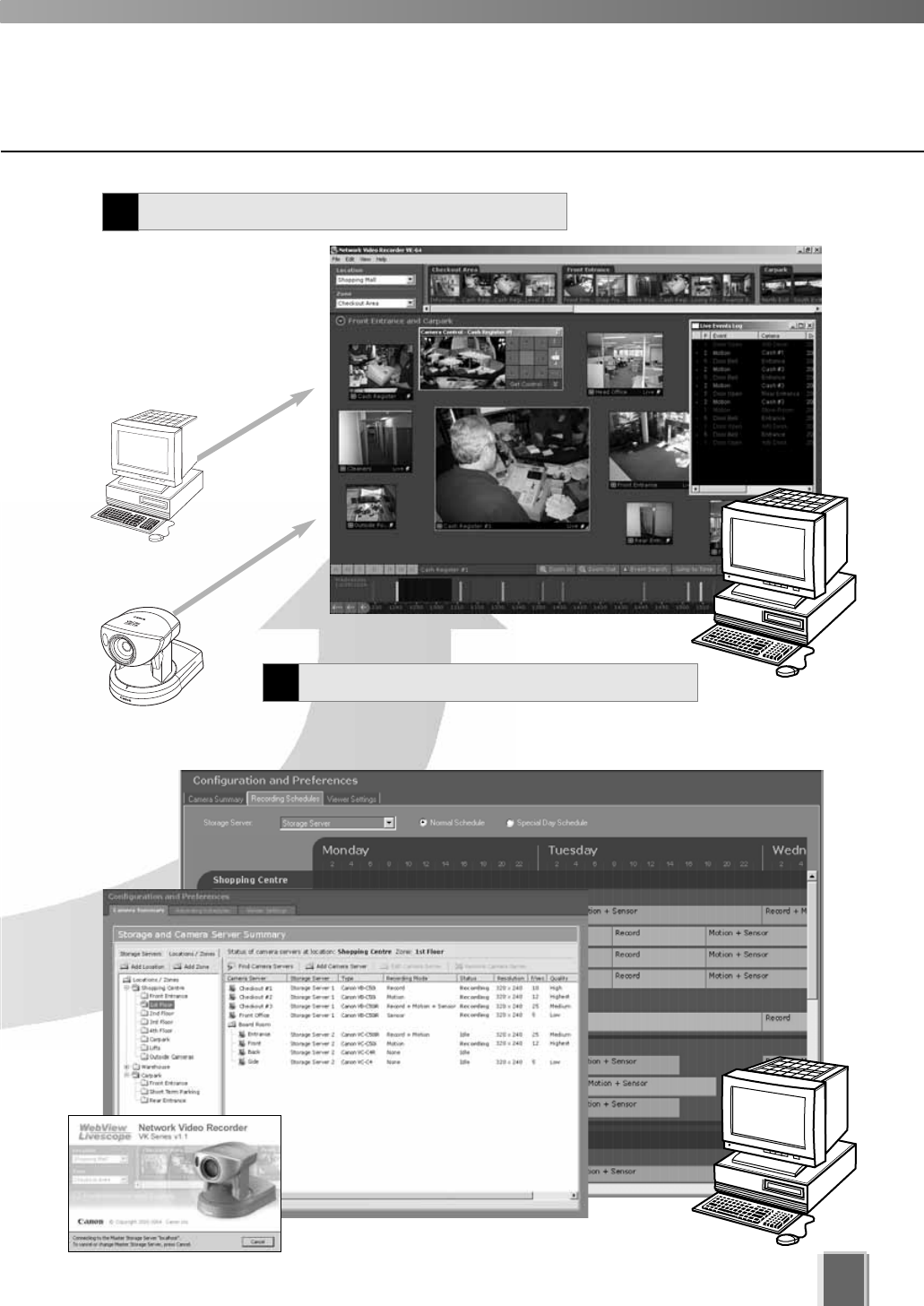
Register Camera Servers and Storage Servers and set
up recording schedules.
Monitor live video and
play back pre-recorded
events in the Viewer
application. From here
you can customize the
Viewing Area and save
Layouts.
Configure Recording Settings
3
Create and save Viewer Layouts
4
Pre-recorded
video from
Storage Server
Live video from
Camera Servers
Supported Camera Servers
12
Canon Camera Servers
The table below lists the Camera Servers that are supported by VK-64.
This information is correct as at September 2005.
For the latest information, please refer to our WebView Product web
page: http://www.canon.com/webview
Camera Server Firmware Versions
VB-C50i VB-C50iR Ver. 1.1 Rev. 33 or later
Ver. 1.0 Rev. 68 or later
Ver. 1.0 Rev. 33 or later
VB-C10 VB-C10R Ver. 1.0 Rev. 26 or later
VB150 Ver. 1.1 Rev. 30 or later
VB101 Ver. 3.0 Rev. 68 or later
VB-C50Fi
VB-C50FSi
If using a VB101, you can make use of a single camera
connected with VK-64 at a time.
If using a VB150 with multiple cameras, there are restrictions
on frame rate. Refer to your VB150 User’s Manual for details.
Note
Firmware Upgrade
The latest information concerning firmware can be found on the following Canon Web site:
http://www.canon.com/webview/
Operating Environment
13
This information is correct as at September 2005.
For the latest information, please refer to our WebView Product web
page: http://www.canon.com/webview
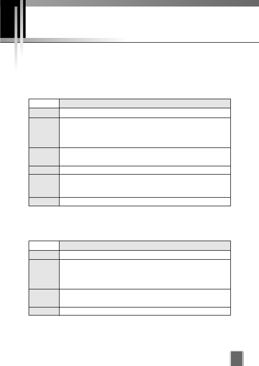
Viewer System Requirements
Storage Server System Requirements
Minimum
CPU Pentium 4 2.2GHz or greater
Operating
System
Memory 1GB RAM or greater
For more than 16 Camera Servers, 1GB or greater required.
Hard Disk
Display 1024 x 768 with 16 bit color
A high performance video card is desirable. With PCI video cards, display performance
may be reduced.
Sound
Minimum
CPU Pentium 4 2.2GHz or greater
Operating
System
Windows 2000 Server (with SP4)
Windows 2000 Professional (with SP4)
Windows XP Professional (with SP2)
Windows Server 2003 Standard Edition (with SP1)
Memory 1GB RAM or greater
For more than 48 Camera Servers, 1.5GB or greater required.
Hard Disk
The requirements for Storage Server will vary according to the environment you will use
(number of Camera Servers, setting of recording frame rate etc.). It is also dependent on
pre-event recording settings. Please contact dealers that handle Canon products for further
information. If using Windows XP Professional SP2, follow the procedures as described on
the following page for configuring your Windows firewall settings.
If using Windows XP Professional SP2, follow the procedures as described on the following
page for configuring your Windows firewall settings.
Audio playback support is necessary for event notification alert sounds.
20GB HDD or greater, SCSI or IDE, NTFS formatted
2GB HDD or greater
Windows 2000 Server (with SP4)
Windows 2000 Professional (with SP4)
Windows XP Professional (with SP2)
Windows Server 2003 Standard Edition (with SP1)
Operating Environment
14
Before starting operations with VK-64
It is recommended that you perform tests under actual
conditions before starting operations.
Recording and display of live videos may not be provided as
configured because many factors (such as network environment and
PC performance) affect the actual performance of VK-64.
When the load on your computer CPU and hard disk is high, the
specified frame rate may not be available, or the video recording may
be interrupted or the Viewer operation may take longer. Also, when
available disk space is low, the disk load may increase and the video
recording may be interrupted due to deletion of the recorded video file
(tP.24).
Using anti-virus and firewall software may affect Storage Server and
Viewer operations.
When using a proxy server
If you use a proxy server, recording frame rate may not be
achieved as specified or live video monitoring may be
interrupted. Also, communication between the Storage Server
and Viewer may occasionally be disconnected.
When using the Audio feature (VB-C50i, VB-C50iR and VB-C50FSi)
The Admin Viewer supports audio transmission and reception.
Audio recording is not available.
The audio and video may be out of sync.
Depending on the performance of your PC and network
environment, the audio stream may be interrupted.
The audio feature is not available via a proxy server.
If you use a PC on which anti-virus software is installed, the
audio stream may be delayed or the audio stream may be
temporarily interrupted.
Note
Using the Storage Server with Windows XP SP2
If your Storage Server is not installed on the same PC as your Viewer, you will need to change
your Windows firewall settings for the Storage Server on the PC with Windows XP SP2.
After installation of the Storage Server on a PC with Windows XP with SP2:
1. From the Windows Start menu, launch the Control Panel.
2. In Control Panel, select Windows Firewall. If Windows Firewall is not shown, select
Security Center and then select Windows Firewall.
3. In the Windows Firewall dialog, select the Exception tab and then click Add Port....
4. In the Add a Port dialog, enter a name for the Storage Server, e.g., ‘VK-64 Storage
Server’.
Enter the Port number as ‘80’. Make sure the TCP protocol is selected and click OK.
5. In the Windows Firewall dialog, your Storage Server is now listed. Make sure it is
enabled (checked). Click OK to close the dialog.
Settings are now complete.
If more than ten camera servers out of all registered ones cannot be connected to Storage Servers,
the CPU load will be heavy and Storage Server and recording operations may take longer.

Chapter 1
Installation
This chapter outlines the installation of the Storage Server and Viewer.
PART 1: INSTALLATION & CONFIGURATION
Before you begin installation...
16
Suggested Network Configurations
It is highly recommended that Storage Servers and Viewers be used on private networks.
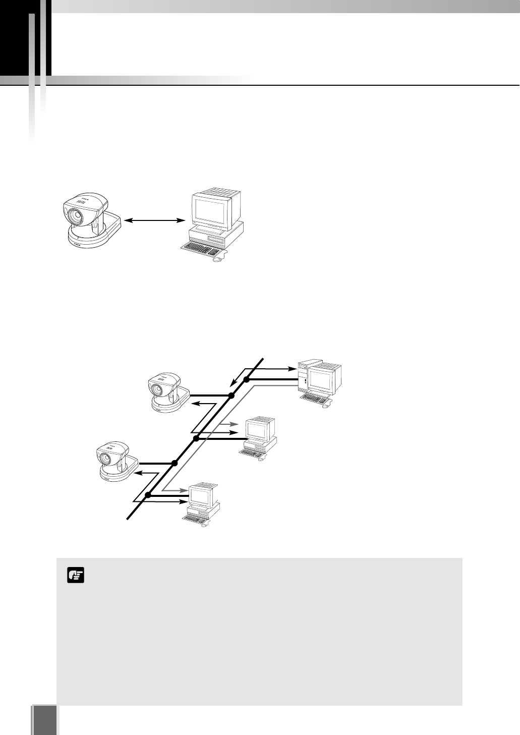
When Viewing and Recording with one PC
When you Install VK-64, you can select to install both the Storage Server and Viewer
software on the same computer.
When Viewing and Recording with Several Viewers
Storage Server (recommend separate hard
drive for recorded video).
Storage Server
Viewing Recorded Events and Monitoring
Viewer
Record video to the
Storage Server
Storage Server
View live and recorded video Viewer
View live and recorded video Viewer
Receives video and
controls camera.
Receives video and records footage.
Install Storage Server and Viewer on one PC and
Viewer on several other PCs.
VB-C50i
Server &
Viewer
Viewer
Viewer
Having many Viewers accessing the same Camera Servers and
Storage Servers will affect system performance.
Installation of both Storage Server and Viewer on a single PC causes a
heavy load on your PC. If you use VK-64 with many camera servers or
the frame rate for live video is high, install each application on separate
PCs.
If the maximum frame rate for live viewing is 10 fps or more, viewing
with a low capacity PC may take longer, the specified frame rate may
not be achieved, recording frame rate may be lower or recording may
be interrupted. Please reduce the live viewing frame rate or use a
separate PC.
Note
17
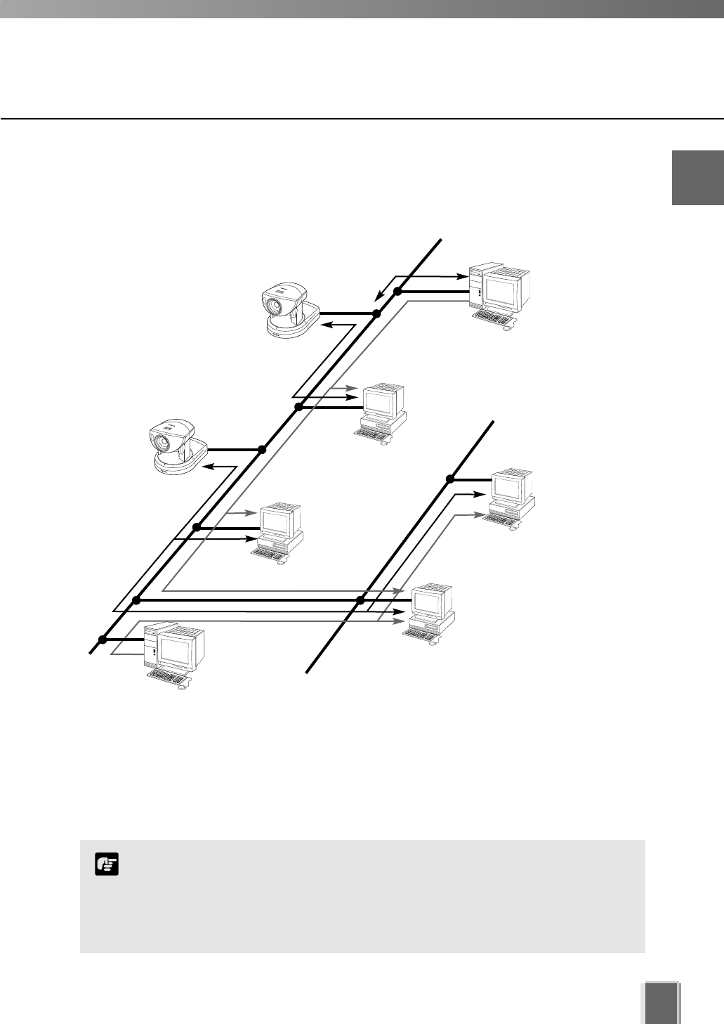
When using multiple Storage Servers and Viewers
Receives video and
records it.
Receives
video and
records
footage.
Plays back
recorded video
Plays back
recorded video
One or more Storage Servers can be used on a network and Viewer applications can be
configured to play video from more than one Storage Server. For each Viewer, a Master
Storage Server (tP. 18) is defined for saving information such as zones and locations of
cameras, as well as saving Viewer layouts created by the user.
Record video to the
Storage Server #1
Master Storage Server
Record video to the
Storage Server #2
Storage Server
View live and recorded events
Viewer
More than one Storage Server can be added to
a network. Viewers can receive playback video
from more than one Storage Server.
Receives video and
controls camera.
View playback video
from Storage Server #1
and #2
View playback video
from Storage Server #2
View playback video
from Storage Server #1
You can operate VK-64 with up to three Storage Servers using any
combination of ‘VK-64 Storage Server’ and ‘VK-16 Storage Server’. Up
to five Viewers can connect to the Storage Servers at the same time.
If you wish to install Storage Servers and Viewers on multiple
PCs, you’ll need to purchase the necessary licenses separately.
Note
1
Installation
Storage
Server
Viewer
Viewer
Viewer
Viewer
Storage
Server
Before you begin Installation...
18
Setting up the Camera Servers
First make sure the firmware is the required version or later (as specified in the
table tP. 12).
Check to ensure the Camera Server has been correctly installed and that the initial
settings (network settings) have been made. Then connect to the network.
For procedures on installing and setting up Camera Servers and cameras, please see
the User’s Manual supplied with the Camera Servers and cameras.
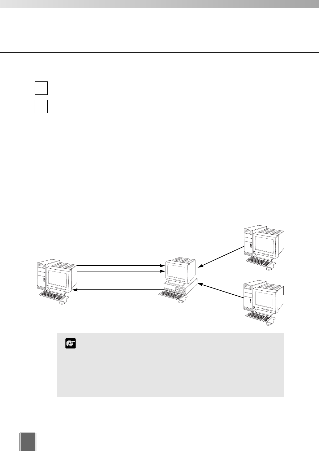
When using multiple Storage Servers...
If multiple Storage Servers are being used, you should decide which one is the Master
Storage Server.
A typical multiple Storage Server arrangement could be:
Master Storage Server
Play Video to Viewer
Save Camera Server information
Save Zones and Locations
Save Viewer Layouts
Play video to Viewer
Play video to Viewer
Storage Server #2
Storage Server #3
Load Camera Server information
Load Zones and Locations
Load Viewer Layouts
1
2
It is recommended that all Viewers within a system use the
same Storage Server as a Master Storage Server. This ensures
that all Viewers use the same Zones, Locations and Viewer
Layouts.
For correct operation, the time setting of all PCs within a
system (including Storage Servers and Viewers) must be
correct.
Note
Viewer
About the Master Storage Server
A Master Storage Server is the Storage Server which a Viewer will connect to in the first
place. Information about Camera Servers, Locations and Zones and Viewer Layouts are
stored on the Master Storage Server.
19
Installation Procedures
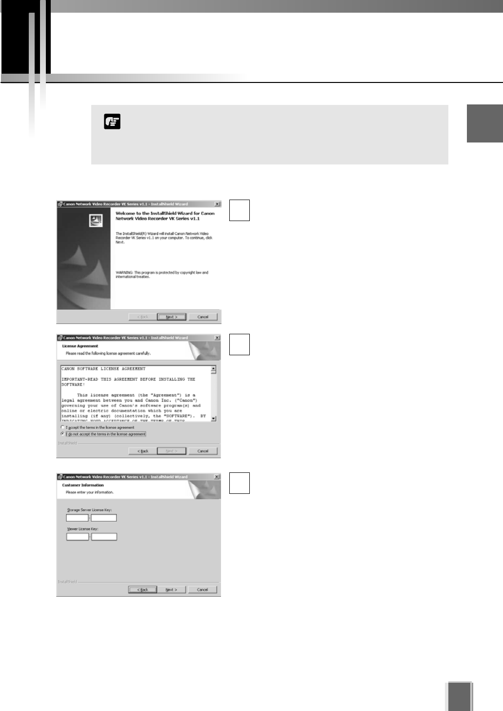
Starting up the Installer
Insert the Network Video Recorder
installation disc into your CD drive. After a
moment, the Welcome screen appears.
Click Next to continue.
If the installer does not automatically load,
open the CD directory in Explorer and
browse to locate Setup.exe. Double-click to
begin installation.
The Software License Agreement screen
appears. Read the agreement carefully.
Click the radio button, I accept the terms in
the license agreement and then click the
Next button to continue.
Enter your License Key(s) and click the Next
button. Your License Key is indicated on the
‘About License Key’ included in the package.
1
2
3
1
Installation
Types and number of licenses you can install vary according to the
product you have purchased. If additional Storage Server and
Viewer installations are required, you will need to purchase the
necessary software for each PC.
Note
20
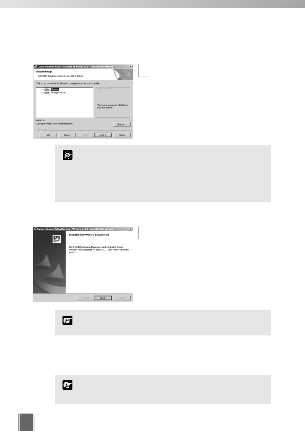
Depending on your License Key, you will
be presented with one or both of the
following applications shown below:
Viewer
Storage Server
It is recommended to keep the Install To:
path as is. Click the Change... button to
choose another installation path if necessary.
Click Next to continue (or view Tip below).
When you click Next, installation will proceed
and a progress bar will be displayed.
When the InstallShield Wizard Completed
screen displays, click the Finish button.
Installation is now finished.
In future, if you need to check your product
type, refer to the ‘About’ box of the Storage
Server or Viewer.
4
5
Installation procedures
If the Storage Server is installed, it will be automatically started
after installation.
Note
Upgrading from Version 1.0
When installing over an earlier version, VK-64 will attempt to use settings from your
previous installation. It is important to verify your settings after installation.
You cannot use v1.1 Viewer with a v1.0 Storage Server, nor can you
use a v1.0 Viewer with a v1.1 Storage Server. When installing, make
sure you install components that have the same version number.
Note
Click the ‘Help’ button to obtain details on the type of
installation. The type is indicated by the icon next to the
application to be installed. You can set a custom install here.
Click the ‘Space’ button to view the amount of hard disk space
required in order to install VK-64. A list of drives is shown.
In either dialog, click ‘OK’ to return to the installation steps.
Tip

Chapter 2
Configuring the
Storage Server
This chapter shows Administrators how to start and stop the Storage Server
if necessary. It also explains how to configure the Camera Server proxy for
the Storage Server, set disk space used, set event notifications
and configure users.
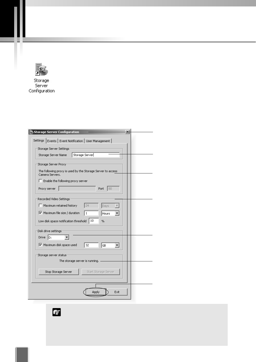
Storage Server Configuration
22
Enter a proxy address for
connecting to Camera Servers.
Enter a name for your Storage
Server.
Click the camera icon or
right-click the title bar to display
the ‘About’ box.
Set Maximum Retained History,
Maximum file size / duration and
Low disk space threshold.
Set maximum disk space used for
each device.
Storage Server status indicator.
Storage Server start and stop
buttons.
Click Apply to save changes when
you modify settings from each tab.
VK-64 can record to any drive that Windows treats as a ‘fixed
drive’. Removable drives and network drives are not supported
unless the drives are explicitly allowed to be treated by Windows as
fixed drives. To check the type of drive, right-click on the drive
within Windows Explorer, select ‘Properties’ and note the ‘Type’
displayed.
Note
Adjusting the Storage Server Settings
The Storage Server Configuration dialog, Settings tab allows you to configure:
Storage Server name Proxy for Camera Servers Recording and Drive settings
Launching Procedure
Double-click the Storage Server Configuration desktop icon.
Alternatively, from the Windows Start menu select:
Programs > WebView Livescope > Network Video Recorder VK Series v1.1
> Storage Server Configuration.
23
2
Configuring the Storage Server
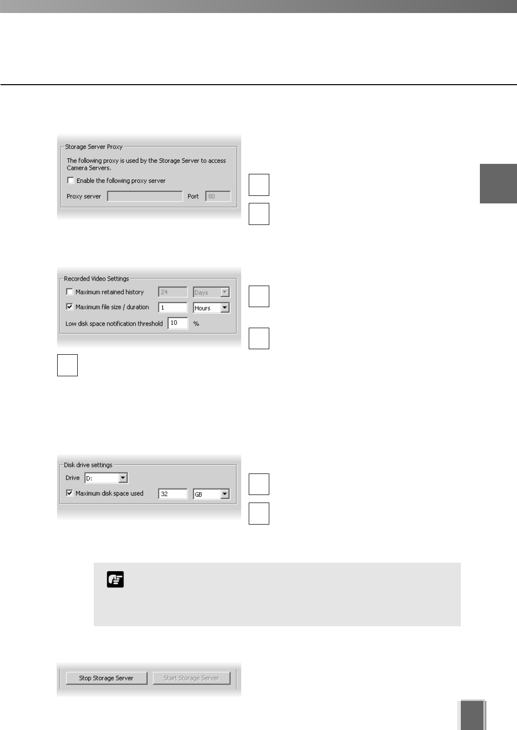
If the Storage Server needs to access Camera
Servers outside the LAN, you may need to
configure proxy settings (see user note tP. 14).
In the Storage Server Proxy field, tick the
Enable the following proxy server box.
Enter the Proxy server address and Port.
Enter the Storage Server Proxy Address
1
2
In the Recorded Video Settings field, set:
Maximum retained history - Enter a
value from 1 to 999 and then select Days
or Weeks from the drop-down menu.
Maximum file size / duration - Select
MB or Hours and enter a value from
1 - 24 for Hours or 32 - 1024 for MB; for
example, ‘100 MB’ or ‘24 Hours’. This will
establish the maximum size used for each
file of recorded video.
Enter Recorded Video Settings
1
2
3
In the Disk drive settings field, set:
Drive - Select the disk drive to configure,
from the drop-down menu.
Maximum disk space used - Tick the box
and enter a value in Megabytes (MB) or
Gigabytes (GB), for example, ‘D: 50 GB’.
This establishes the maximum disk space used for all video files on the specified drive.
1
2
Low disk space notification
threshold - Enter a percent value.
When remaining space reaches,
for example, 10%, a notification will
be emailed.
Select Disk Drive Settings
If disk space is not enough to cover the specified value configured with
‘Maximum disk space used’, the retained duration of video may be shorter
than the specified period or the recording may be temporarily stopped.
Please be sure to perform sufficient tests before starting operations.
Note
Start or Stop the Storage Server
You can start or stop the Storage Server using
the Start Storage Server/Stop Storage Server
buttons via the Settings tab.
24
Storage Server Configuration
If you need to stop the Storage Server for any reason (such as
maintenance) first inform all users connected to the server!
Tip
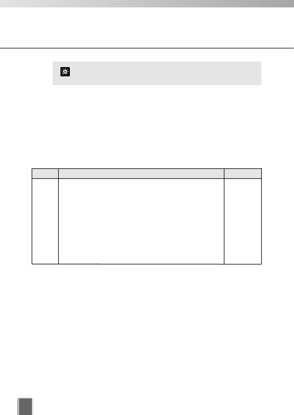
How the Storage Server manages disk space
This section describes the way in which the Storage Server manages its disk space and
determines when old video files should be deleted. It also describes the events and
notifications associated with disk usage.
The Storage Server tracks the unused disk space that is currently available for recording
video and events for each drive and sets some disk warning and error levels based on this.
These levels are used to generate events and alter the behaviour of the Storage Server.
For each of the levels, the system can be configured to provide email notifications when
one of these levels is reached. The levels it uses are shown in the following table.
The Limit level and the Threshold level are determined by the Storage Server, depending
on various conditions and settings. However, an administrator can alter the Low disk level
warning value in order to control at what point a Low disk warning is generated.
The warning is triggered when the disk space available for writing goes below the given
percentage of the total disk space on the drive. For example, for a 100GB disk and a
setting of 10%, the warning would be generated when available space reduces below 10GB.
If Maximum Disk Space Used is set, the warning can also be triggered when the disk space
available for writing goes below the given percentage of the Maximum Disk Space Used on
the drive (if the warning has not already been triggered as above). For example, if the
Maximum Disk Space Used is set to 80GB and a setting of 10%, the warning would be
generated when the available space reduces to 8GB.
For disk space management operating examples, please refer to page 146.
Level Description Warning / error
Low disk
warning
level
Threshold
level
Limit level
This is the level of free space at which an early warning will be generated. This
allows early intervention by an administrator to avoid problems due to running
out of disk space (for example, removing unwanted recording schedules).
This is the minimum free space that can be available in order that old video
files will be retained. If the free space is ever reduced to this level, the Storage
Server starts to delete video files starting at the earliest ones (even if these are
within the "Maximum Retained History" value). However if the oldest file is
currently used in the Viewer (for example for playback of recorded video), it
would not be deleted and the next oldest file will be deleted instead. Deletion
will continue until the free space rises above this threshold again.
This is the minimum free space that can be available in order for recording to
be continued. If the free space is ever reduced to this level, recording will stop
and resume again when the free space rises above this limit again.
Low disk
warning
Low disk dele-
tion
Low disk rec.
stopped
25
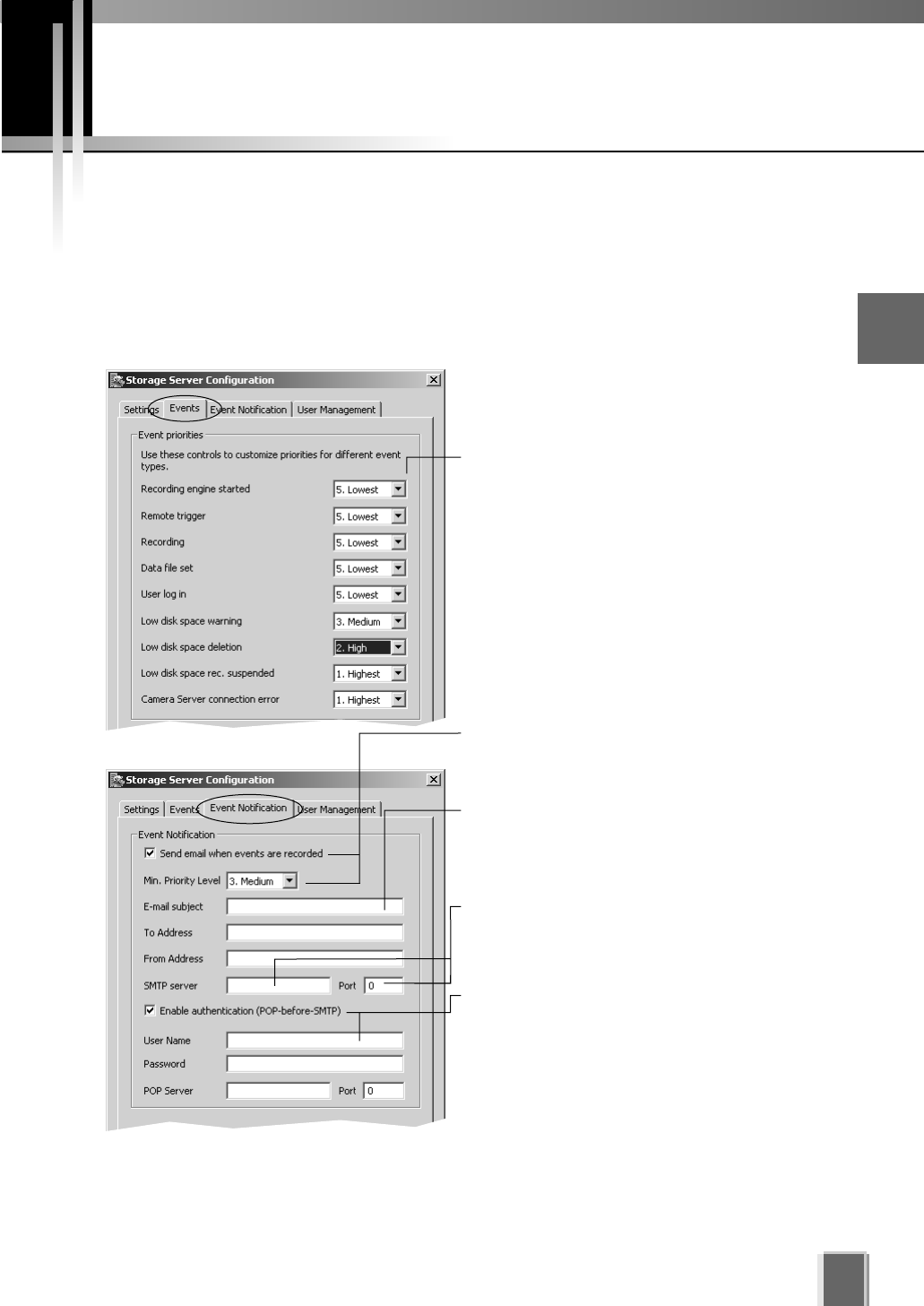
Setting up Event Notifications
Set up a user to receive Event Notification emails
The Storage Server Configuration dialog, Events and Event Notification tabs allow you to
set up event priorities and email notification to a particular user.
Example event notification email...
An event of priority 3 occurred on 8/16/2004 at 16:24:08 PM +1000.
Parking Lot 1: Sensor on
Adjust settings for the ‘Events’ tab and ‘Event Notification’ tab... 2
Configuring the Storage Server
Enter the email subject line, for example,
‘Immediate Action Required’. Enter the address
of the recipient and enter your from address.
Enable email notification and select a
priority. Events of that priority and above will
lead to notification emails.
Select a suitable event priority from the
drop-down menu for each event type listed.
The priority of an event created by a manual
recording using ‘Record Now’ (tP. 111) will
always be Priority 1. It cannot be changed from
this dialog.
The events associated with ‘Recording engine
started’, ‘Data file set’ and ‘User log in’ do not
appear in a Viewer’s Timeline, Live Events Log
or Event Search Dialog.
Enable authentication (POP-before-SMTP) for
connection and enter User Name, Password
and POP Server details.
If this is enabled, the Storage Server will
attempt to perform a POP login before sending
email that may be required for some SMTP
servers.
Enter a Host Name or IP address and Port
Number of mail server for outgoing mail.
26
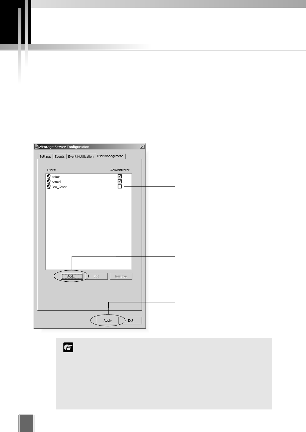
Setting up Users
Tick to enable user to have
Administrator privileges (full
access to configuration
functions).
Adding and Editing Users
The Storage Server Configuration dialog, User Management tab allows you to set up users
and their privileges. Administrators have access to the Viewer including Camera Server
setup, recording schedules and Viewer setup. Operators only have access to live video and
pre-recorded video on Storage Servers they have permission to access.
The User Management tab is laid out in the following manner:
Users list - Lists all users who can access the Storage Server.
Add / Edit / Remove - Allows you to add users, edit passwords and remove users.
Use the Add button to add
users to this field. There is no
limit to the number of users you
can add.
Click Apply to save changes.
Users who have Operator status cannot configure, register and
change Camera Servers, or configure and change recording
schedules.
By default, a user ‘admin’ is created with the password ‘NVR’. It
is strongly recommended that this is changed after installation.
It is necessary to set up users on all Storage Servers. A
particular user should be set up to have the same password on
each Storage Server.
Note
27
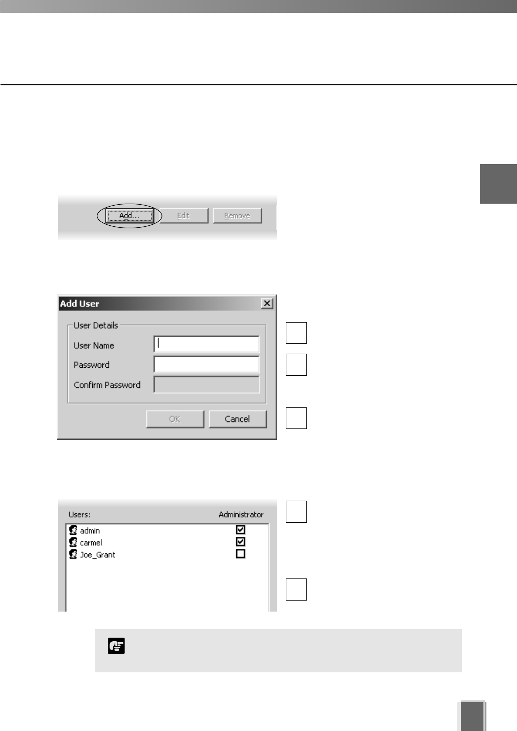
User Management tab - Add Users
The Add User dialog is used to add new users to the system.
Step 1: Click the Add button
In the User Management tab, click the
Add button to bring up the Add User
dialog.
Step 2: Enter user details
In the Add User dialog, enter the
following details:
Enter the user’s User Name (up
to 20 characters).
Create a password for the user
(up to 20 characters). The Confirm
Password field will become
active. Re-enter the password.
When you have finished, click
OK. The dialog will close and the
user will appear in the user list.
Step 3: Assign user status to Administrator if necessary
In the user list under
‘Administrator’, tick the box to
give the new user full access
to Network Video Recorder
configuration functions, otherwise
leave unchanged.
Click Apply to save changes.
1
1
2
2
3
The VK-64 Administrator status is independent of the Windows
Administrator status.
Note
2
Configuring the Storage Server
28
Setting up Users
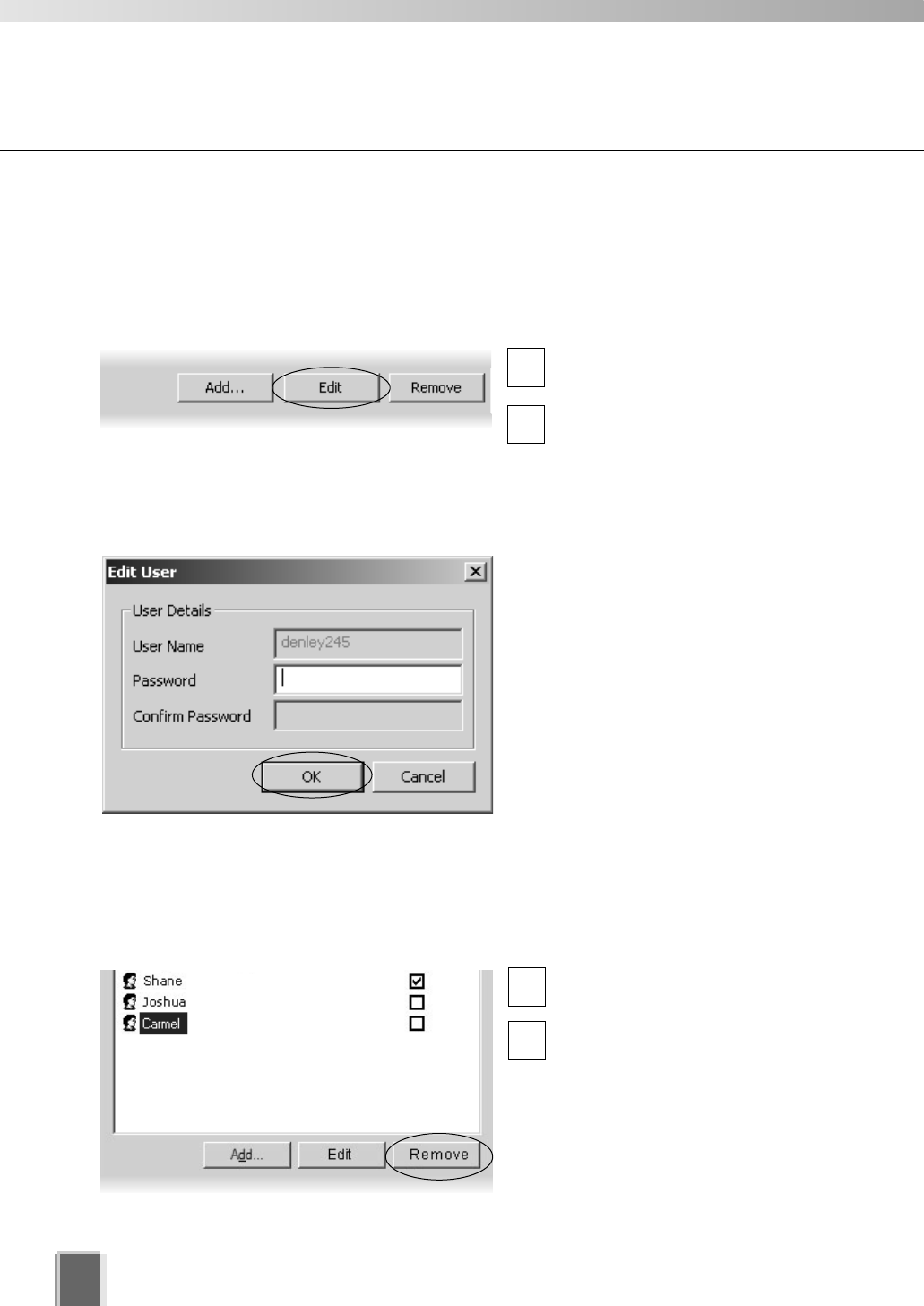
User Management tab - Edit Users
The Edit User dialog is used to edit the password for an existing user. To edit a user:
Step 1: Click to select user, then click the ‘Edit’ button
Click an entry in the user list to
select it.
Click the Edit button below the
user list to bring up the Edit User
dialog.
Step 2: Change user details
In the Edit User dialog, enter the new
password for the user (up to 20
characters). The Confirm Password
field will become active. Re-enter the
new password.
Changes are kept when you click OK.
1
2
User Management tab - Remove Users
Click to select user, then click the Remove button
Click a user entry in the user list
to select it.
Click the Remove button.
1
2

Chapter 3
Starting the
Viewer
This chapter describes how to start and login to the Viewer and
connect to the Storage Server.
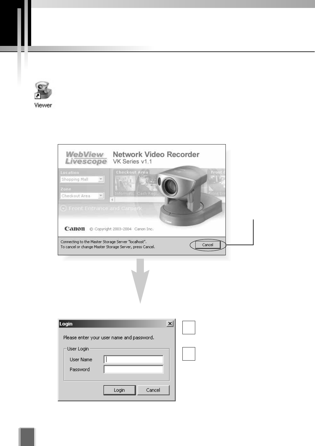
Starting the Viewer
30
Click Cancel to
setup a different
Master Storage
Server (discussed
on the next page)
or wait until the
Login dialog
appears.
Enter your User Name and
Password, and then click the
Login button.
Proceed to Chapter 4.
After a moment, the Login dialog appears...
Launching Procedure
Double-click the Viewer desktop icon.
Alternatively, from the Windows Start menu select:
Programs > WebView Livescope > Network Video Recorder VK Series v1.1
> Viewer.
After launching, the Network Video Recorder VK-64 v1.1 start-up screen appears...
The default User Name is: admin
The default Password is: NVR
1
2
31
3
Starting the Viewer
In order to retrieve information, you must be connected to a
Master Storage Server, even if it is on the same computer as the
Viewer.
After installation, the Master Storage Server is set to ‘localhost’.
This indicates that the Viewer will attempt to use the local
computer as its Master Storage Server.
Note
After installation, the default user ‘admin’ with the password ‘NVR’
is setup. It is strongly recommended that this is changed after
installation.
Tip
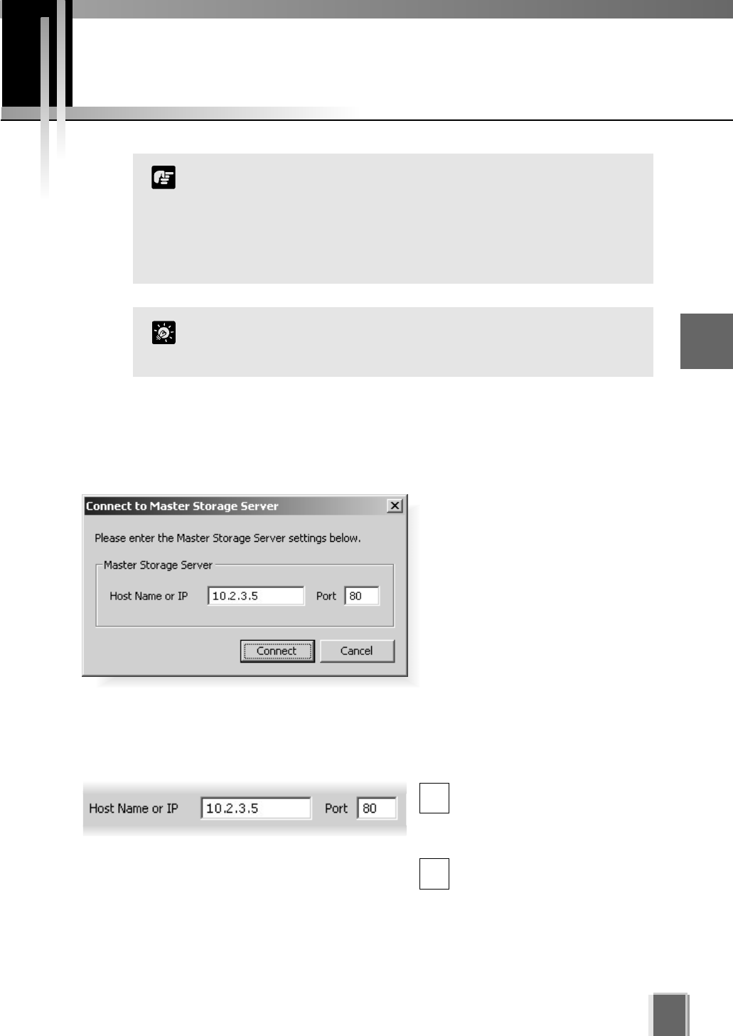
If you clicked the Cancel button
during launch, the Connect to
Master Storage Server dialog will
appear.
A different Master Storage Server
can be selected by overwriting the
existing Host Name or IP address
and Port number with another.
Setting the Master Storage Server
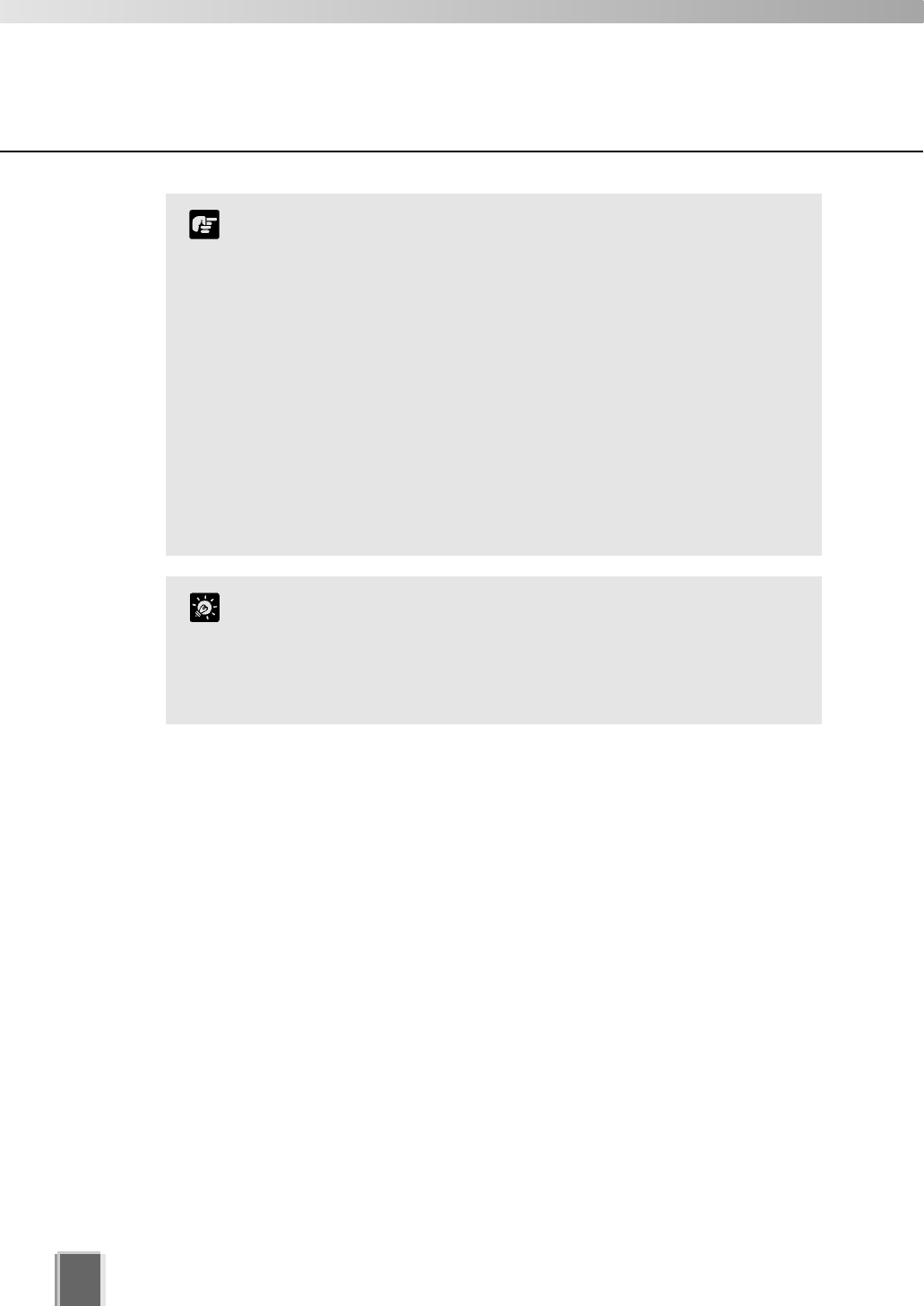
If you are unsure of the address to use, see your System Administrator.
Enter a Storage Server address and Port number
Enter a Host Name or IP
address for a new Master
Storage Server, then enter the
Port number.
Click Connect to continue.
1
2
If you installed the Viewer and Storage Server on separate PCs, be sure to configure a
Master Storage Server in the first place. By default, the Master Storage Server is set to
‘localhost’.
Changing the Storage Server
32
If you need to use a proxy server, set it in the Internet
Properties, LAN Settings dialog. To open, select Start > Settings
> Control Panel > Internet Options. When the Internet Options
dialog opens, select the Connections tab. From here, click the
LAN Settings... button to open the LAN Settings dialog. You can
adjust your proxy settings from here.
If using a proxy server between a Viewer and a Storage Server,
it should be one which does not perform response buffering.
Proxies which are configured to perform response buffering
may lead to delays in sending small amounts of data (such as
events) from the Storage Server to the Viewer. Squid is an
example of a proxy which does not perform response buffering,
so it is recommended for use between the Viewer and
Storage Server. The Apache proxy server does perform
response buffering so is not recommended.
Note
The dialog will also be shown when the Storage Server is
stopped.
If you want to use the same machine the Viewer is running on
as the Master Storage Server, set the Host Name or IP to
‘localhost’ in this dialog.
Tip
Changing the Storage Server

Chapter 4
System Configuration,
Before You Begin
This chapter gives a brief overview of the Viewer Configuration process (which
is outlined in Chapters 5 to 7). This is intended for Administrators.
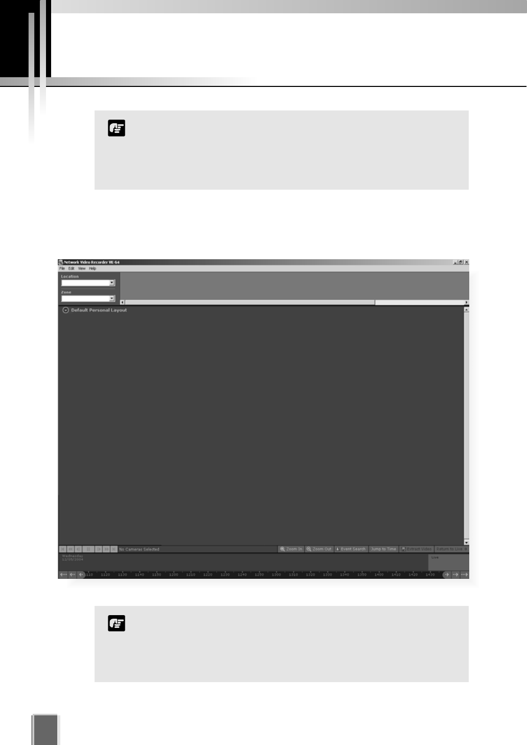
When the Viewer accesses a Master Storage Server which has not been set up with
camera information, the entire Viewer window is initially blank. You will need to configure
the Viewer using the Configuration and Preferences window.
After the Viewer has launched...
34
This chapter is for users with Administrator privileges. Only
Administrators can alter Viewer configuration and preferences.
If you are a user with Operator privileges, proceed to Chapter 8.
Chapter 8 and following chapters explain the various controls
and functions in the Viewing Screen.
Note
Configuration settings made by Administrators are not protected
from other Administrators making changes to these settings from
another Viewer. The last settings made to a Storage Server are the
ones that are used. It is recommended that only one Administrator
perform configuration on a network at a time.
Note
A configuration process diagram is given on the following pages. Configuration is discussed
thereafter. When you have finished configuration, select View > Viewing Screen to return
to the Viewer.
35
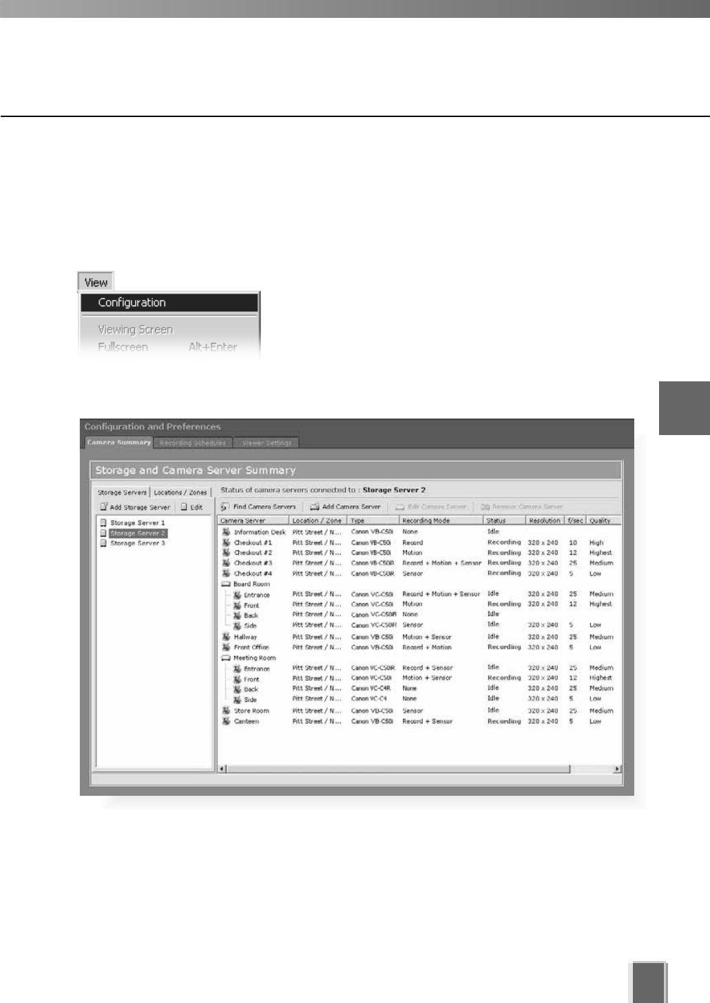
Accessing the Configuration and Preferences screen
To open the Configuration and Preferences screen:
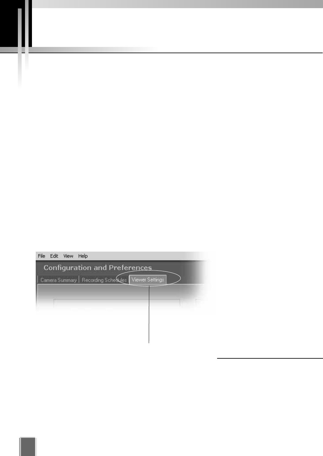
In the Menu Bar, select View > Configuration
The menu bar is located at the top left of the Viewing
screen. Select the menu bar item, View > Configuration.
The Configuration and Preferences screen opens with
the Storage and Camera Server Summary window
displayed.
An example configuration is shown below. 4
System Configuration, Before You Begin
36
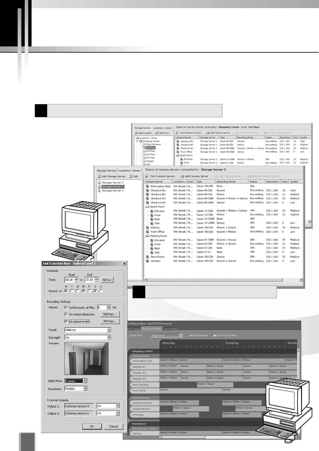
System Configuration Process
After configuring the Storage Server and launching the Viewer, you are now ready to
configure the Viewer application for monitoring, recording and playing back video. The flow
diagram below shows the Viewer configuration process via the Configuration and
Preferences Screen.
The first step is to register
Storage Servers and Camera
Servers with the Viewer. You will
also need to create Locations and
Zones.
These tasks are
done in the Camera
Summary window.
For recording video, set up Normal and Special Day
Recording Schedules in the Recording Schedules window.
Register Storage and Camera Servers
1
Set up Recording Schedules
2
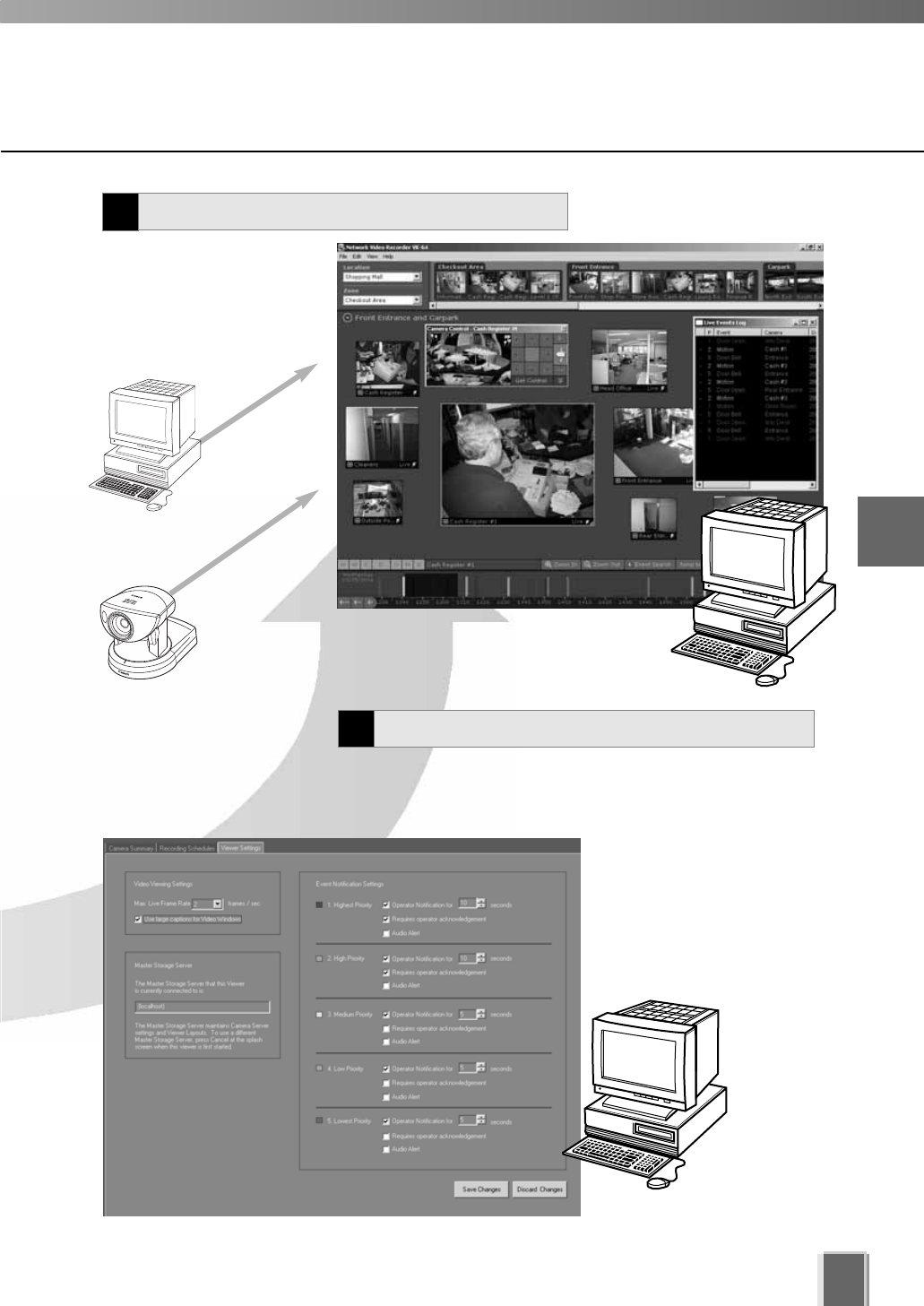
37
Adjust live viewing frame rate, identify an individual Viewer’s
Master Storage Server and set priorities for event
notifications in the Viewer Settings window.
Monitor live camera images
and play back pre-recorded
events in the Viewer
application. From here you
can customize the Viewing
Area and save Layouts.
4
System Configuration, Before You Begin
Pre-recorded
video from
Storage Server
Create and Save Viewer Layouts
4
Set up Viewer Settings (optional)
3
Live video from
Camera Servers
Configuration and Preferences screen
38
About the Configuration and Preferences screen
The Configuration and Preferences screen is used for configuring one or more Storage
Servers and for setting up preferences on a Viewer computer. Storage Servers may include
the local computer being used or another computer on the network.
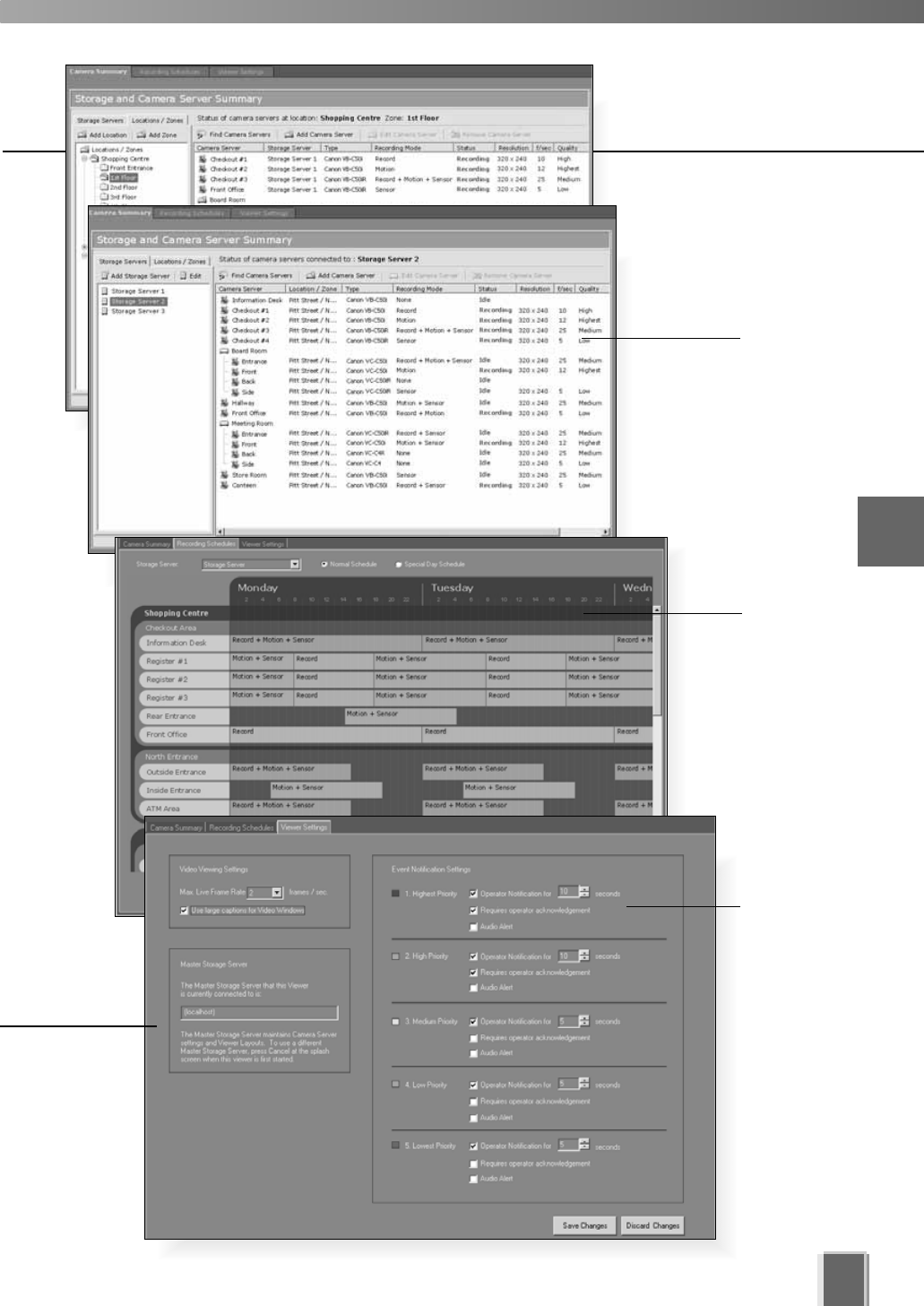
There are three windows in the Configuration and Preferences screen used for
connecting and configuring VK-64 settings:
Camera Summary - add a new Camera Server to a zone and search for existing
Camera Servers on the network. This is discussed in Chapter 5.
Recording Schedule - set up recording schedules for each known camera
and specify events for triggering recording. You can also set special day schedules
such as public holidays. This is discussed in Chapter 6.
Viewer Settings - set up event priorities and change the live video frame rate. The
current Master Storage Server is indicated. This is discussed in Chapter 7.
Selecting a Configuration and Preferences window
When the Configuration and Preferences screen is launched, three tabs are displayed.
The default selection is the first tab, the Camera Summary window.
Click another tab to bring up
the corresponding window.
39
4
System Configuration, Before You Begin
Storage
and
Camera
Summary
windows
Recording
Schedule
Viewer
Settings

Chapter 5
Register Storage Servers
and Camera Servers
This chapter outlines how to register Storage Servers and Camera Servers
and to manage Locations and Zones. This is intended for Administrators.
Camera Summary Window
42
About the Storage and Camera Server Summary Window
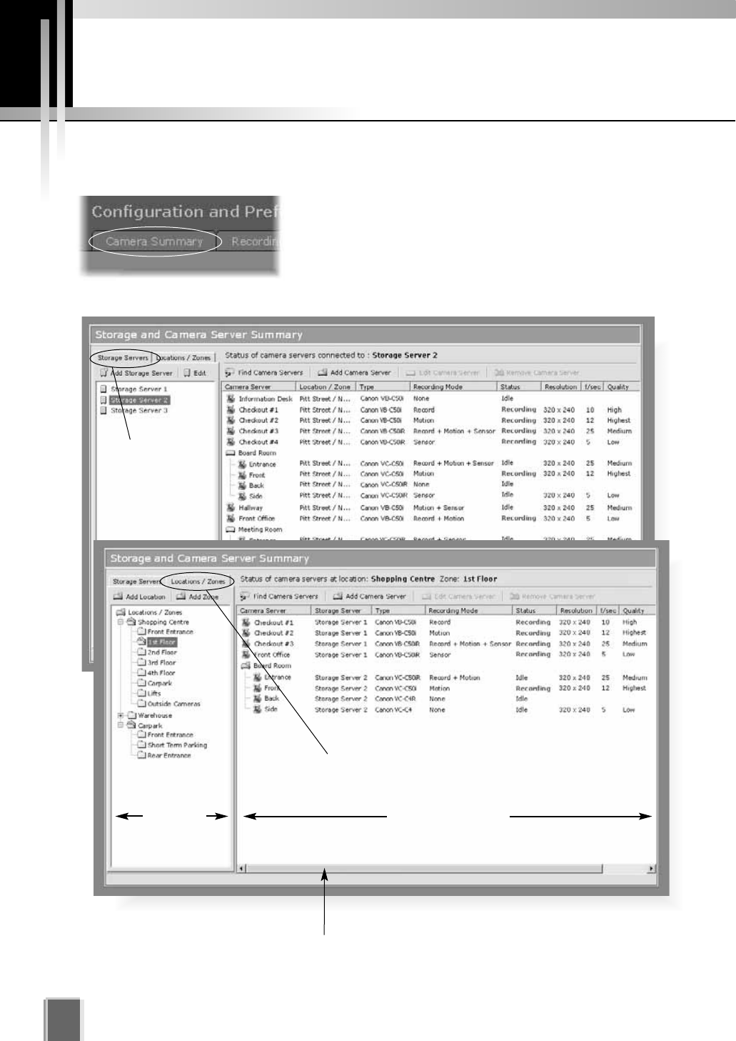
Click the Camera Summary tab to open the Storage
and Camera Server Summary window.
The window consists of two sub-windows which are
opened by their respective tabs, Storage Servers and
Locations / Zones.
Tree Area Summary Area
Locations / Zones tab selected.
Storage
Servers tab
selected.
Click and drag scrollbar(s) to view any portions
of the Summary Area that are not visible.
tP. 4 6
tP. 4 7
43
5
Registering Storage Servers and Camera Servers
The following options are available via the Storage Servers tab:
Add Storage Server - Allows you to register a
Storage Server with the system (up to three is
recommended).
Edit - Allows you to change the address of the
selected Storage Server.
Select a Storage Server from the tree in the left panel. The right panel will update with a list
of Camera Servers recorded by the Storage Server you selected.
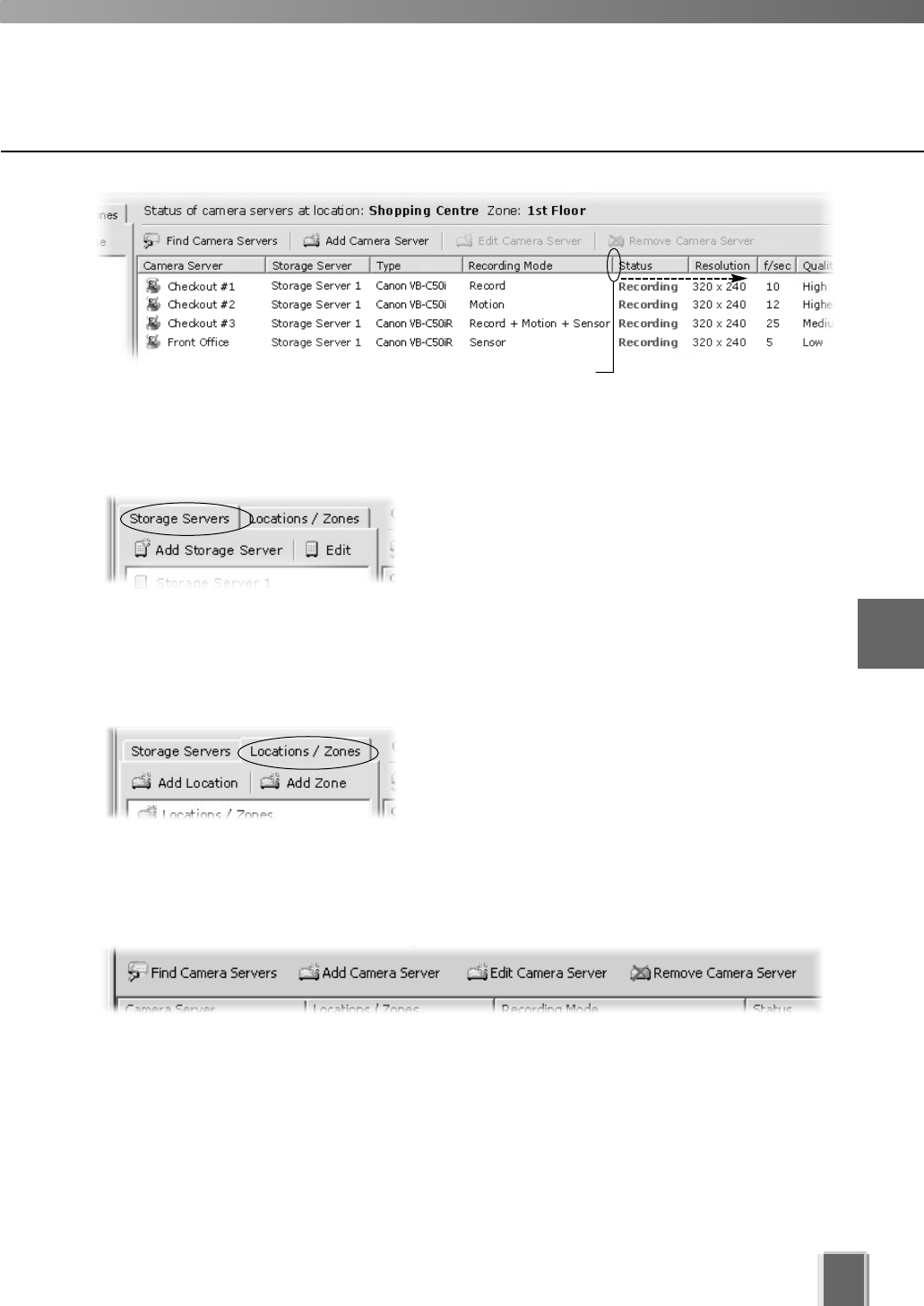
Other functions in both sub-windows
Camera server functions are located on the right-hand panel regardless of which tab is
selected:
Find Camera Servers - Allows you to initiate a network search for unlisted camera
servers on the LAN.
Add Camera Server - Allows you to add a new Camera Server to the system.
Edit Camera Server - Allows you to edit an existing Camera Server’s settings.
Remove Camera Server - Allows you to remove a Camera Server from the system.
Storage Server and Location / Zone options
Click and drag divider line to the right to reveal full values.
The following options are available via the Locations / Zones tab:
Add Location - Allows you to add a new location to
the system.
Add Zone - Allows you to add zones to locations.
When you select a zone within a location in the left panel, a list of cameras in that zone is
displayed in the right panel.
46
P. 4 7
Location #3
Locations and Zones
44
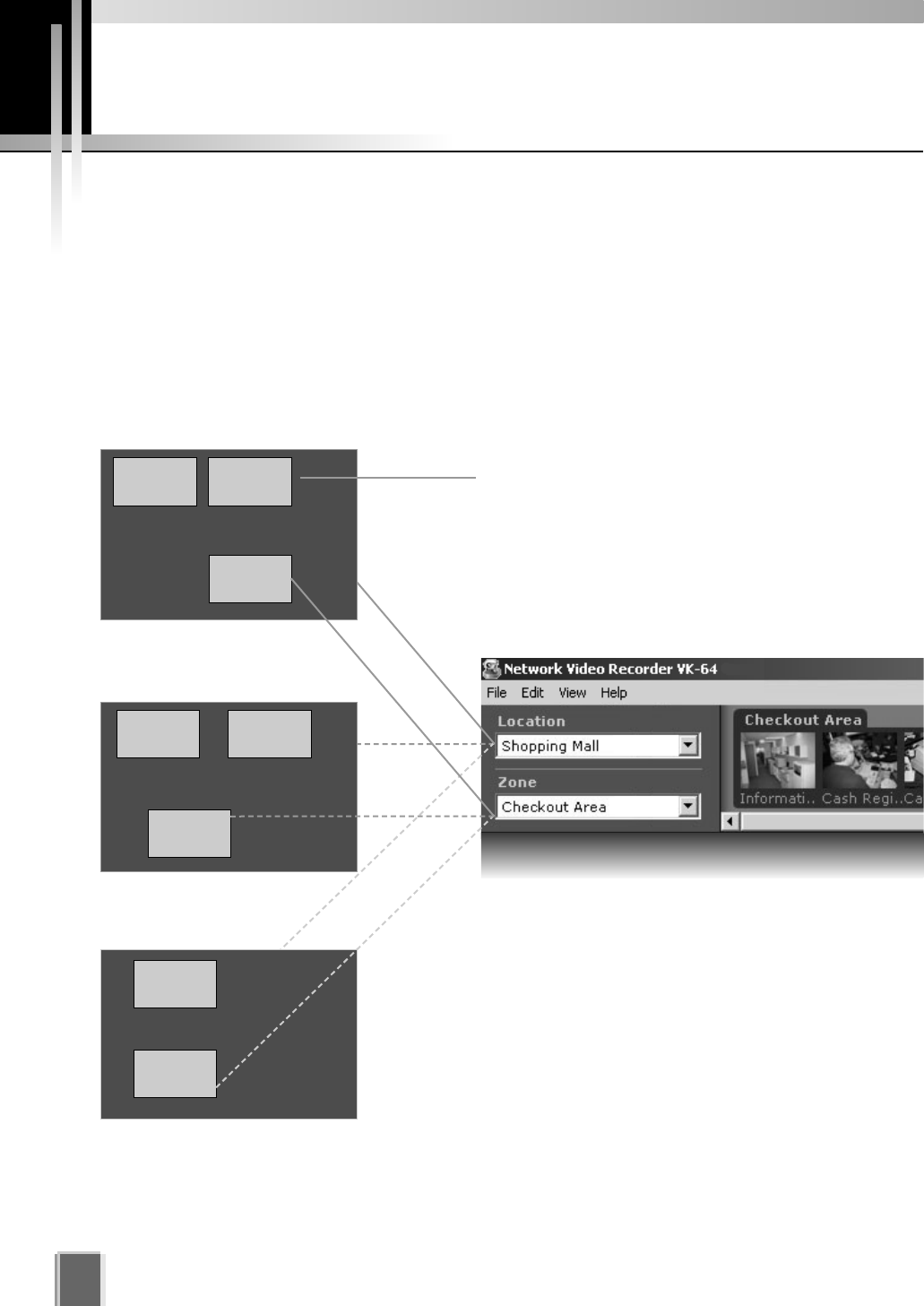
About Locations and Zones
Cameras are grouped into Locations and Zones. Locations could include an office building,
shop or school. Zones are sub-categories of Locations, that is, a zone could be assigned
to each floor in the office building and specific areas in a shop such as a cash register. A
number of cameras can be grouped into one Zone and a number of Zones can be grouped
into a Location.
The diagram below illustrates an example of physical Locations and Zones on a
VK-64 network which could be the Internet, Local Area Network or both. Viewer access is
via the Location and Zone drop-down menus.
Once configured, Locations and Zones are
selected from the Viewing Screen Camera
Selection area. When you select other
locations, their Zones become accessible.
Zones are different areas of the one Location.
Location #2
Zone #4 Zone #5
Zone #6
Zone #8
Zone #7
Location #1 (Shopping Mall)
Zone #1 Zone #2
Zone #3
45
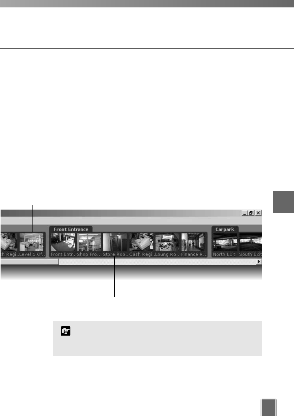
When a Location is selected from the drop-down menu at left, all of the Zones associated
with the Location will appear to the right as camera thumbnail images.
This tab containing four thumbnail images indicates that there are four cameras in the Zone.
This tab containing six thumbnail images indicates that there are
six cameras in the Zone.
5
Registering Storage Servers and Camera Servers
The Location/Zone hierarchy is independent of the grouping of
cameras into Storage Servers. For example, a single Storage
Server may record video from multiple Locations, and cameras
from a single Location can be recorded to multiple Storage Servers.
Note
Camera Summary - Add, Edit and Delete a Storage Server
When using multiple Storage Servers, you will need to configure the Storage Servers via
the Add Storage Server dialog shown below.
A Storage Server must first be connected and running on the network as follows:
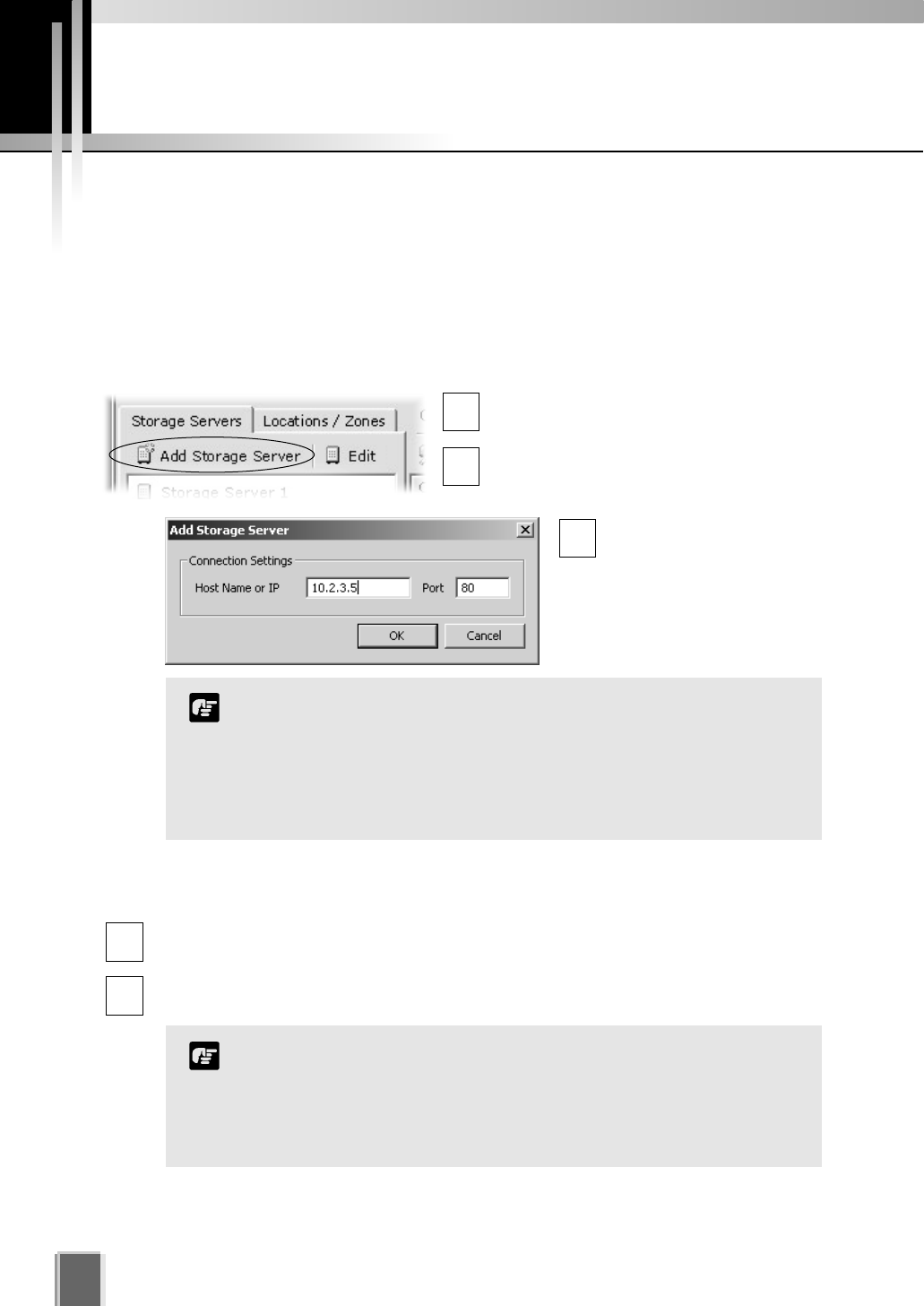
Click the Add Storage Server button on the Storage Servers tab
In the Camera Summary window, select
the Storage Servers tab.
Click the Add Storage Server button.
The Add Storage Server dialog opens.
Configure Camera Summaries
46
Enter connection settings
and click OK.
Double-click a server in the list; or click to highlight it and click the Edit button. The
Edit Storage Server dialog appears with the selected server entry displayed.
Modify the entry and click OK to close and save changes.
This function lets you change the network address used to
access a particular Storage Server in case the address has
changed.
The entry for the Master Storage Server cannot be edited or
deleted.
Note
1
3
2
1
2
To edit a Storage Server:
It is not recommended to add the same Storage Server more
than once (for example, by using Host Name one time and using
a corresponding IP address another time).
If you add a Storage Server with a different configuration (such
as one managed by another Master Storage Server), your
original Locations and Zones will be lost.
Note
47
5
Registering Storage Servers and Camera Servers
Camera Summary - Add, Edit or Delete a Location/Zone
You can easily add a new location to your system, then add zones to the new location
folder. For example, a location could be a supermarket and zones inside that location can
include cash register areas, supermarket aisles and entrances.
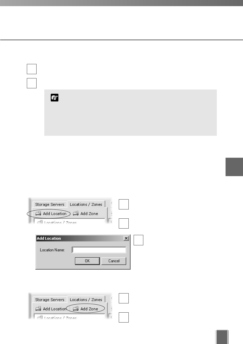
Step 1: Click the Add Location button on the Locations / Zones tab
In the Camera Summary window, select
the Locations / Zones tab if it is not
already selected.
Click the Add Location button.
The Add Location dialog opens.
Enter the name of the new
location (up to 20 characters),
then click the OK button.
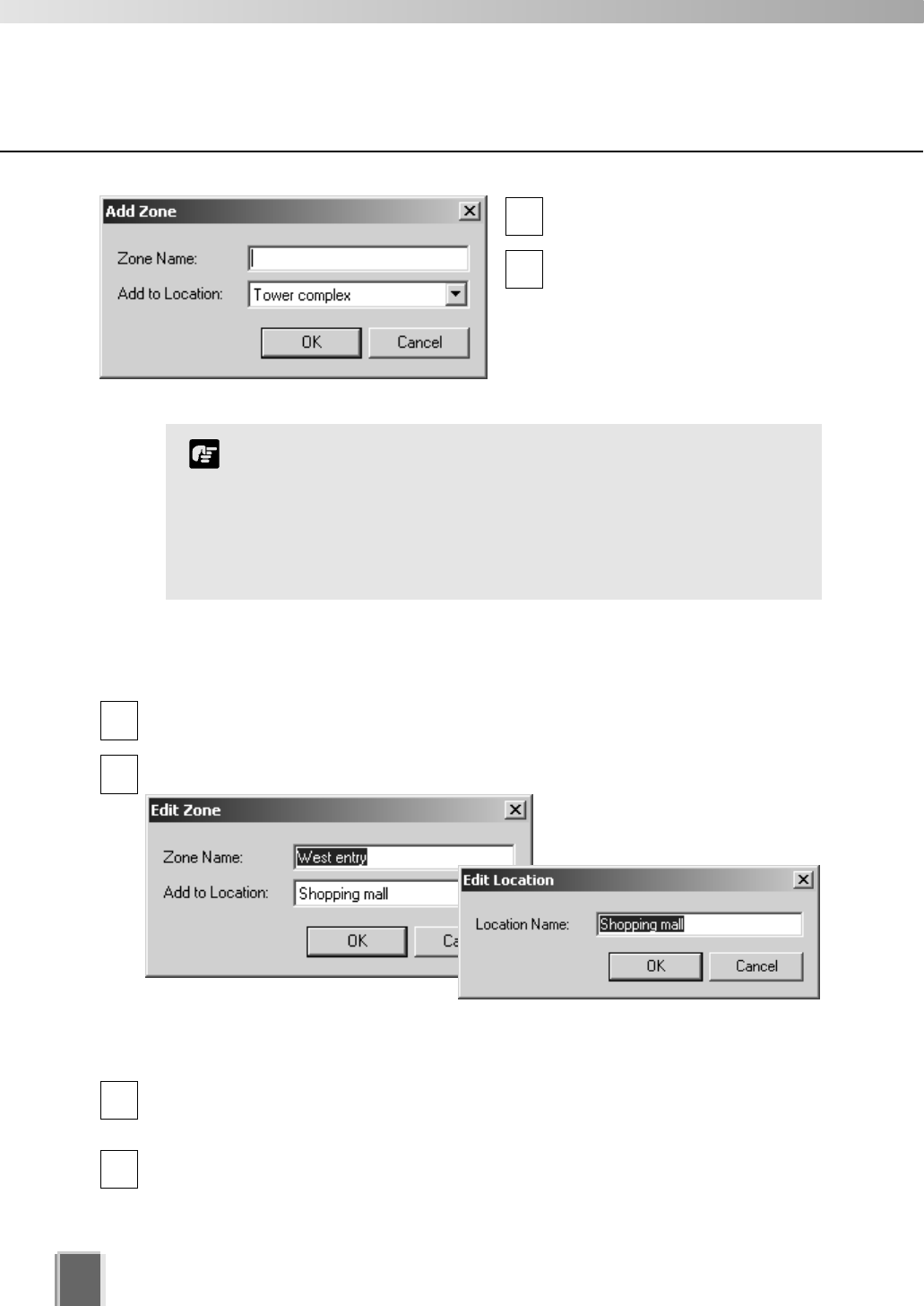
Step 2: Click the Add Zone button on the Locations / Zones tab
In the Camera Summary window, select
the Locations / Zones tab if it is not
already selected.
Click the Add Zone button.
The Add Zone dialog opens.
Click a Storage Server in the list to highlight it and select Delete from the Edit menu.
Alternatively, press the Delete key on your keyboard.
A confirmation dialog will open. Click Yes to continue or No to cancel the operation.
A deleted Storage Server is removed from the list and the Master
Storage Server no longer recognizes it. If it was running when
removed from the list, it will continue to run. It can be re-added to
the system with all associations to Camera Servers intact and can
also be added to a different Master Storage Server. If this is done,
all Location, Zone, thumbnail and Layout information for cameras
associated with this Storage Server will be lost.
Note
1
3
2
1
2
1
2
To delete a Storage Server:
48
Configure Camera Summaries
To edit a Location or Zone:
Double-click a Zone or Location. The respective Edit Zone or Edit Location dialog
opens.
Make any changes and click OK to close the dialog.
To delete a Location or Zone:
Click a Zone or Location to select it and select Delete from the Edit menu.
Alternatively, click a Zone or Location in the list to select it, then press the Delete key
on your keyboard.
You will be prompted to confirm deletion. Click Yes to continue or No to cancel the
operation.
If you want to add a Zone to another location not listed, you
must first create the Location before you add the Zone.
Each Location name must be unique and each Zone name
within a Location must be unique.
There is no fixed limit on the number of Zones and Locations
that can be added.
Note
1
2
1
2
Enter the name of the new zone
(up to 20 characters).
Select a location from the
drop-down menu in the Add to
Location field, then click the OK
button.
The selected zone will now
appear in the specified Location
folder.
3
4
The camera names listed are those specified by the camera server.
Please refer to the camera and camera server User's Manual for
details on how to specify camera names. ('Camera Name' includes
VB-C50i, VB-C50FSi, VB-C50Fi and VB-C10. 'Device Name' includes
VB150 and VB101.)
Note
Camera Summary - Find Camera Servers
The VK-64 Network Video Recorder System can be expanded to include more Camera
Servers. You can easily locate Camera Servers via the Find Camera Servers button.
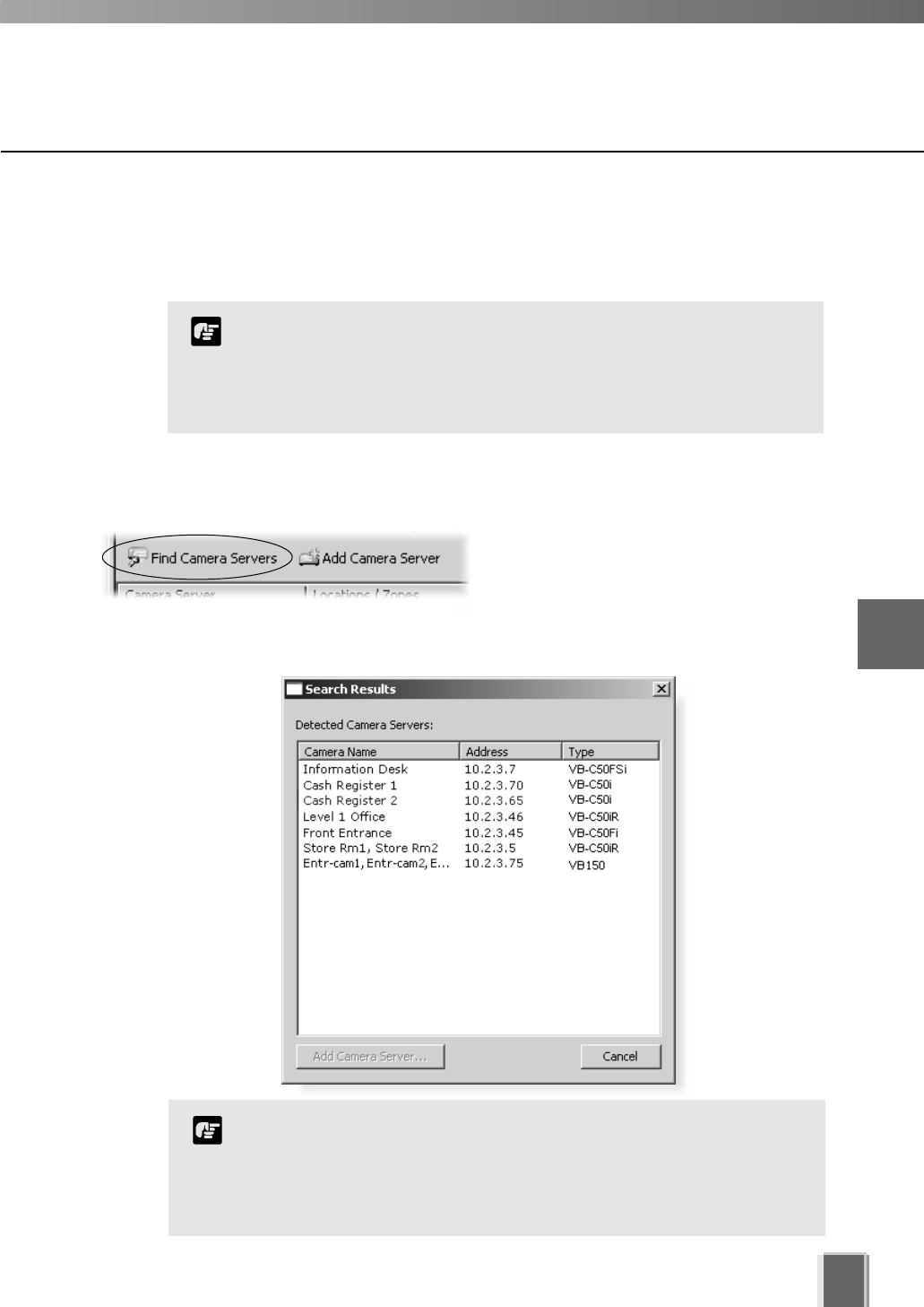
Step 1: Click the Find Camera Servers button
In the Camera Summary window, click the
Find Camera Servers button which is
located above the right-hand panel in both
the Storage Servers and Location/Zones
window.
The Search Results dialog opens and a list of detected Camera Servers will appear.
49
5
Registering Storage Servers and Camera Servers
Configure Camera Summaries
When you initiate the Find Camera Servers function, your
computer searches the Viewer’s local subnet for all Camera
Servers connected to it. It will not find Camera Servers on a
different subnet where a Storage Server may be connected for
example, nor find Camera Servers on the Internet.
Note
50
Configure Camera Summaries
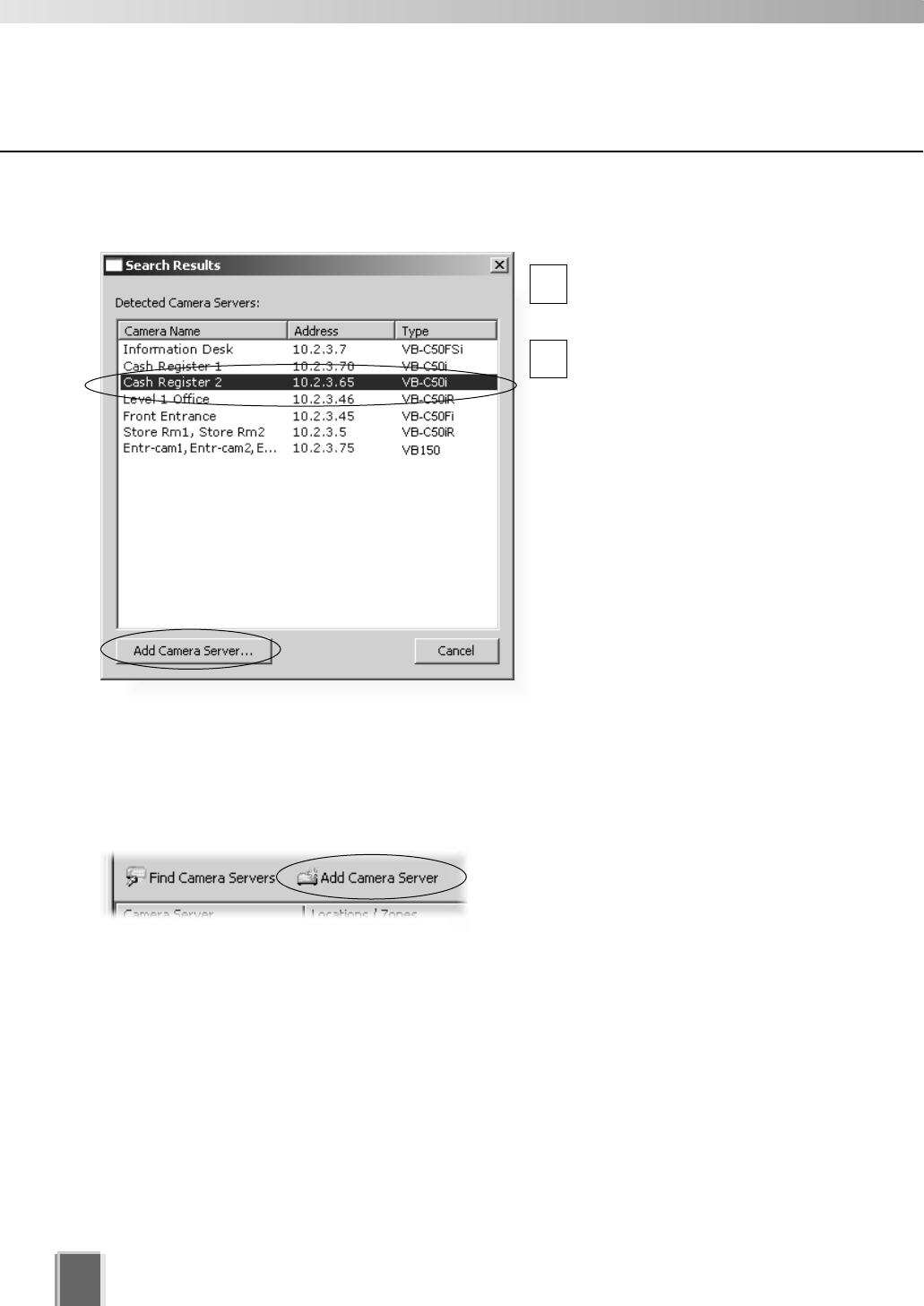
Step 2: Select a new Camera Server
In the Search Results dialog,
click a Camera Server in the
search results list to select it.
Click the Add Camera
Server... button. This will bring
up the Add Camera Server
dialog where you can
configure settings for the
Camera Server.
Alternatively, double-click an
item to bring up the Add
Camera Server dialog.
Using the Add Camera Server dialog
is discussed on the following pages.
You can also launch the Add Camera Server dialog in the following manner:
Click the Add Camera Server button in the Camera Summary window
This will bring up the Add Camera Server
dialog discussed on the following pages.
1
2
51
5
Registering Storage Servers and Camera Servers
For more information on VB150 Video Input settings, please refer to
Chapter 3, Detail Settings, in your VB150 User’s Manual.
Note
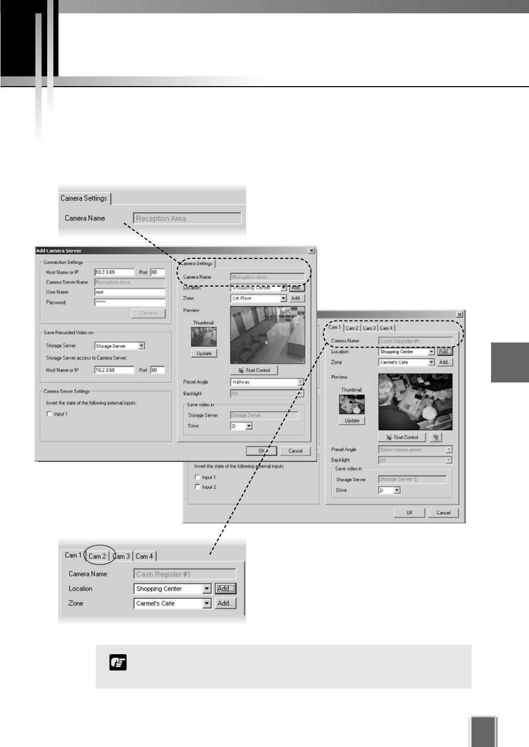
About the Add Camera Server Dialog
The Add Camera Server dialog’s appearance will depend on the type of Camera Server
connected and the number of cameras that have been set up. Differences are in the way
camera selection is presented.
The Add Camera Server dialog for a VB-C50i/
VB-C50iR/VB-C50FSi/VB-C50Fi/VB-C10/
VB-C10R/VB101 or VB150 with the Video Input
set to Single will display a single camera in a
single tab.
The Add Camera Server dialog for VB150 with
the Video Input set to Multiple will show one or
more cameras as tabs (see Note below).
Click a tab to view that camera.
Using the Add Camera Server Dialog
52
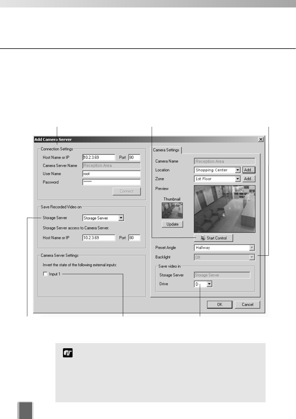
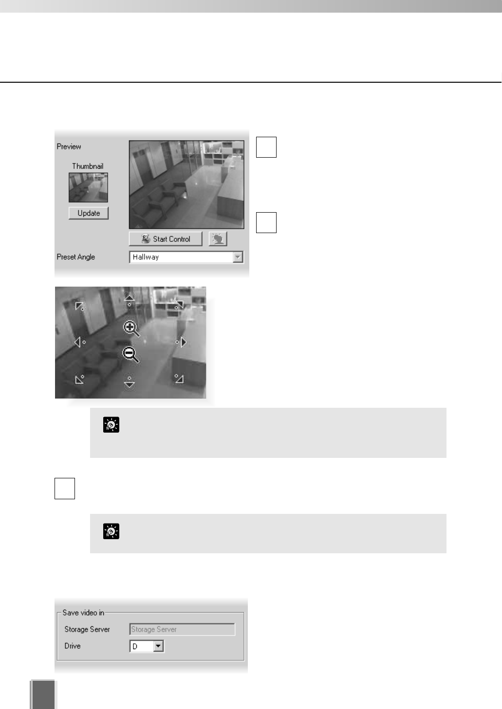
Set up camera position and saved video
The Add Camera Server dialog allows you to set a camera thumbnail image for the Viewer
and to choose a Storage Server for recorded video.
The dialog shown below illustrates an example VB-C10 setup. It could also
represent a VB-C50i, VB-C50iR, VB-C50FSi, VB-C50Fi, VB101 and VB150 with only one
camera setup or in a single mode.
Connection Settings
Set the Storage Server for saved
video, or select ‘Do not record’.
Select a drive on the Storage
Server to save video.
One or more inputs may
show. The states for these
can be ‘inverted’.
Adjust camera angle Set backlight compensation.
The Viewer does not store its own names for camera
servers or sensors. It displays names which are configured and
stored on the Camera Server. Please refer to your VB User’s
Manual for more details on setting names.
These settings specify information about recording. To initiate
recording, refer to Chapter 6 for configuring recording
schedules.
Note
Using the Add Camera Server Dialog
You must click the Connect button before clicking OK to close
the dialog (the OK button is disabled until you do so).
The number of tabs shown for a VB150 does not indicate the
physical number of cameras connected. It indicates the
number of cameras which have been enabled using the VB150
Camera and Video Settings Page. Please refer to Chapter 3,
page 40 of the VB150 User’s Manual for more details.
For VB101 (or VB150 in ‘single mode’), the camera name displayed
is the first camera name in the server’s camera name list. This allows
an Administrator to set the first camera name to be a general name,
applicable to the entire camera server.
If you are using a VB101 or VB150 with the ‘Settings Web page
URL’ other than the default setting ‘admin’, a connection error
occurs when you click the Connect button. Restore the default
setting and try again.
Note
53
5
Registering Storage Servers and Camera Servers
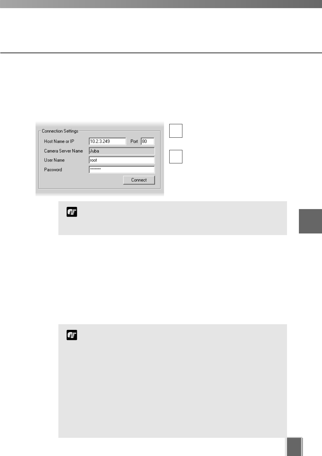
Add a Camera Server - Set connection details
To add a Camera Server, you must specify how VK-64 can connect to the camera
server as follows:
Step 1: Enter Host Name, User Name and Password
Enter the Host Name or IP address,
then enter the port number for the
Camera Server.
Enter a User Name and Password
for connecting to the Camera Server.
Details will be kept on the Storage
Server for use in recording.
1
2
Using the Add Camera Server Dialog
This is the User Name and Password configured on the VB Camera
Server side, not your VK-64 password. If you do not know your
Camera Server user name and password, see your System
Administrator.
Note
Step 2: Click the Connect button
Click the Connect button when you have added the above information.
Once the Viewer has connected with the Camera Server:
For a VB-C50i/VB-C50iR/VB-C50FSi/VB-C50Fi/VB-C10/VB-C10R and VB101, or
VB150 in Single mode, one tab is shown.
For a VB150 in Multiple mode, 1 to 3 additional tabs are added if more cameras are
enabled on the server.
54
Using the Add Camera Server Dialog
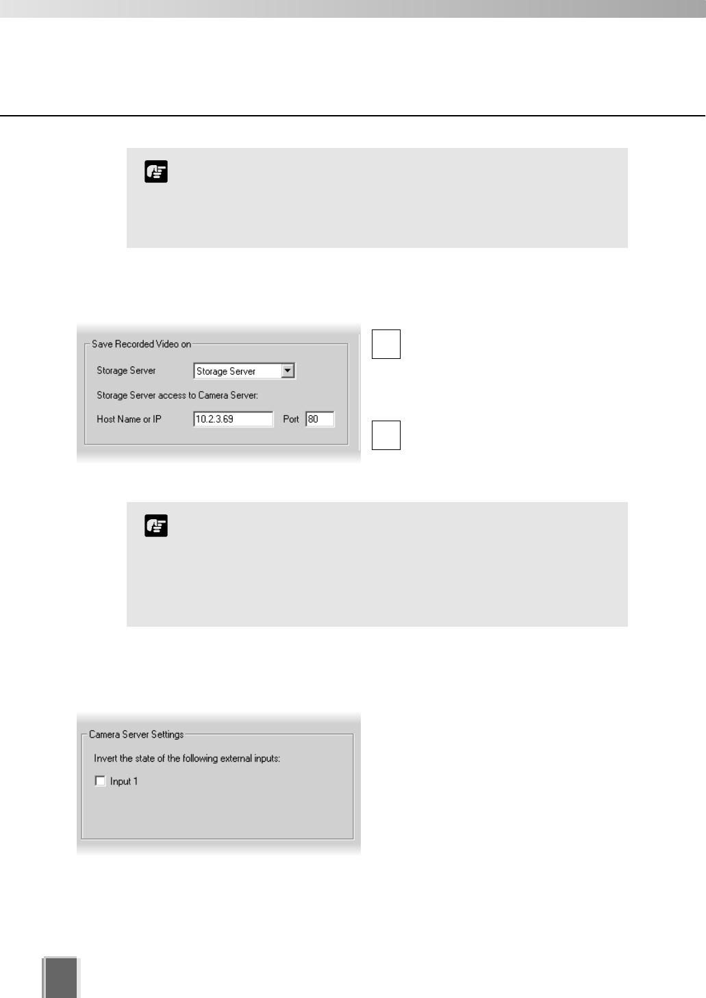
Step 3: Select the Storage Server for recording
Select a Storage Server from the
drop-down menu which lists
pre-configured Storage Servers and
enter the Host Name or IP address
and Port number.
If you do not wish the camera
server to be recorded, select the Do
Not Record option from the
drop-down menu.
1
2
Setting a value for the Storage Server does not mean that video
will be automatically recorded. Please refer to the next chapter
for information on setting recording schedules.
There is a maximum number of 64 camera servers that can be
registered on one Storage Server with VK-64 (or 16 cameras
with Network Video Recorder VK-16 v1.1).
Note
Step 4: Select the input state for the camera server
In the Camera Server Settings field, one
or more Input boxes may display,
depending on the camera server setup. If
a sensor input is received, you can swap
its value from ‘on’ to ‘off’ (with respect to
the operation of schedules) by ticking the
Input box. This acts as a ‘toggle’ control.
If you have a Multi-Terminal Module VB-EX50 unit plugged into a
VB-C50i/VB-C50iR/VB-C50FSi/VB-C50Fi and have configured the
‘Use External Video Input’, video seen in the Viewer will be taken
from cameras connected to the Multi-Terminal unit. Please refer to
the camera server User’s Manual.
Note
55
Using the Add Camera Server Dialog
Camera Summary - Edit Camera Server Settings
The right-hand side of the Add Camera Server dialog may show one or more enabled
cameras (depending on the type of Camera Server you are using). To edit settings:
Step 1: Select a camera tab if available
VB150: Click a tab to display that camera’s
settings.
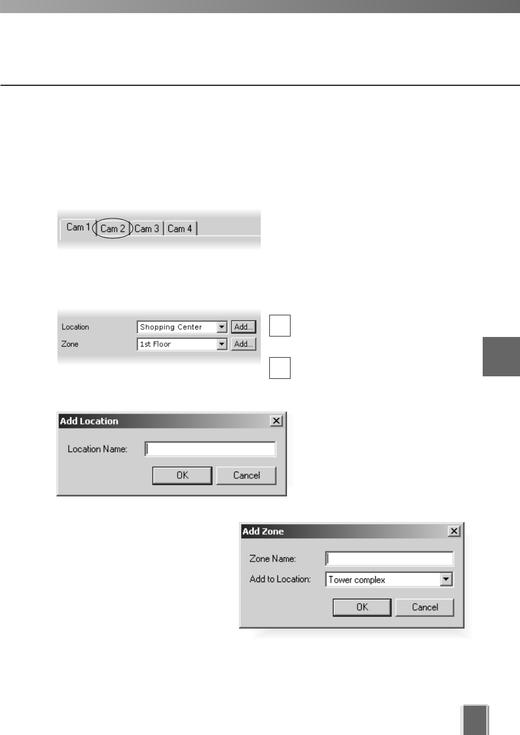
Step 2: Assign a location and zone
In the Location field, select a location
for the camera from the drop-down
menu.
In the Zone field, select a zone for the
camera from the drop-down menu.
If necessary, click the Add... button to
add another Location or Zone. The
respective Add Location or Add
Zone dialog will appear for you to
enter details.
When you have entered details, click
the OK button to close the dialog and
return to the previous dialog.
When you add a Zone in the Add Zone
dialog, you must also add it to a
Location in the same dialog.
Select a location from the drop-down
menu.
Adding zones and locations is discussed on previous pages.
5
Registering Storage Servers and Camera Servers
1
2
56
Using the Add Camera Server Dialog
Step 3: Update and setup camera thumbnail for Viewer
In the Preview area, a camera view is
given. Click the Update button to grab
a current frame from the camera. It will
be re-sized in the preview window and
saved for reference as a Viewing
Screen camera thumbnail.
If you are not happy with the frame,
click the Start Control button. You can
then use your mouse to redirect the
viewing angle and zoom in or out.
1
2
Move the mouse cursor around the image. Arrows
will appear and you can click and drag the cursor in
that direction. The preview will change accordingly.
When you move the mouse cursor to the center of
the image, a zoom in or zoom out control will appear.
For a VB-C50FSi and VB-C50Fi, only zoom is available.
Hold down the mouse on ‘+’ to zoom in.
Hold down the mouse on ‘-’ to zoom out.
Step 4: Select a hard drive for saving video
In the Drive menu, select a hard disk drive
on the Storage Server.
When you have finished configuration, click
the OK button to close the dialog and return
to the Camera Summary screen.
If you do not wish to manually control the camera, choose a pre-defined camera
position (if already configured) from the Preset Angle drop-down menu.
3
Presets need to be configured in advance. Please refer to the
camera server User’s Manual for details on making camera presets.
Tip
If you want to change the thumbnail and the preview area is blank
(and the ‘Update’ and ‘Start Control’ buttons are disabled), click the
‘Connect’ button (located in the Connection Settings field).
Tip
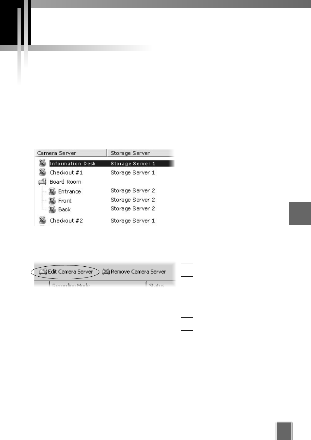
57
Edit and Remove Camera Servers
5
Registering Storage Servers and Camera Servers
Camera Summary - Edit Camera Server
The right-hand portion of the Camera Summary window features the Edit Camera Server
button for editing Camera Servers on your system, regardless of which tab you have
selected (Storage Servers or Locations / Zones). The same dialog as the Add Camera
Server appears, detailing all the aspects of the Camera Server as discussed on previous
pages.
Step 1: Select a Camera Server
In the Camera Server list, click a
server to highlight it.
Step 2: Click the Edit Camera Server button
Click the Edit Camera Server
button to bring up the Edit
Camera Server dialog. This
dialog is identical to the Add
Camera Server dialog (you
can also double-click an entry
to bring up the dialog).
Adjust settings as discussed
on the previous pages, then
click the OK button to close
the dialog.
1
2
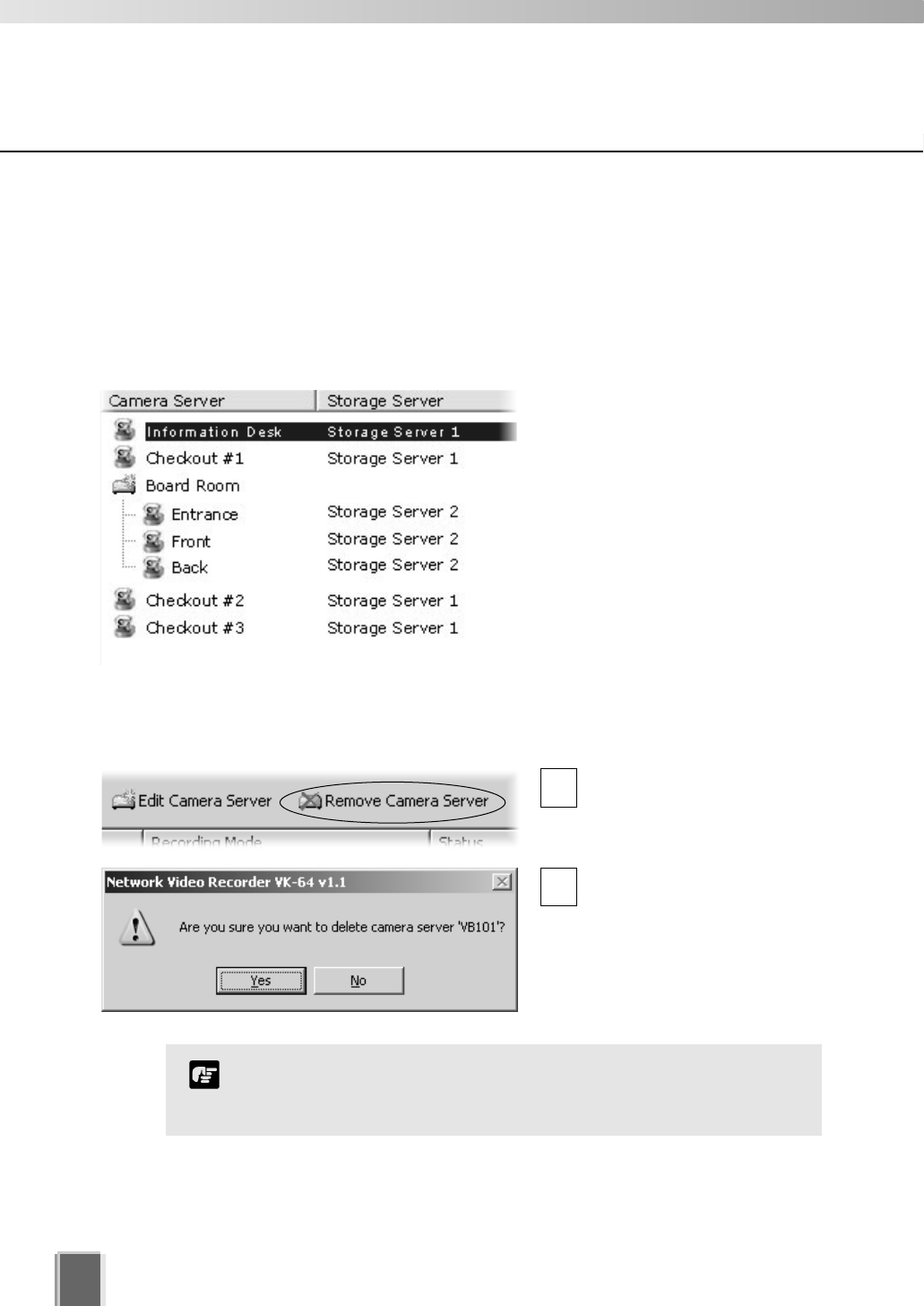
Edit and Remove Camera Servers
58
Camera Summary - Remove Camera Server
The right-hand portion of the Camera Summary window features the Remove Camera
Server button for removing Camera Server(s) from your system, regardless of which tab
you have selected (Storage Servers or Locations / Zones).
Step 1: Select a Camera Server
In the Camera Server list, click a
server to highlight it.
Step 2: Click the Remove Camera Server button
Click the Remove Camera
Server button (you can also
press the Delete key on your
keyboard).
A confirmation dialog will
appear. Click Yes to continue
or No to cancel the operation.
You can add deleted Camera Servers, so long as they are still
connected to the network. However, previous VK-64 settings for
those servers will be lost and default settings will apply.
Note
1
2
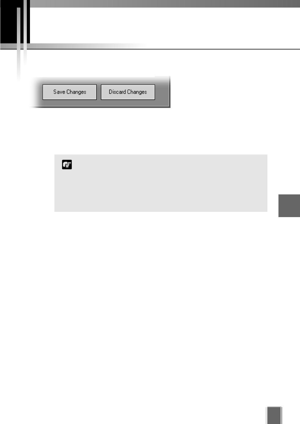
Saving Configuration Changes
59
5
Registering Storage Servers and Camera Servers
Camera Summary - When you have finished configuration
The bottom right-hand corner of
the Camera Summary window
consists of two buttons, Save
Changes and Discard Changes.
Click Save Changes to keep all your settings.
Click Discard Changes to cancel any modifications you have made.
If you wish to return to the Viewer, select View > Viewing Screen from the menu bar.
Saving changes to the Camera Summary window will save changes
to your Master Storage Server and other affected Storage Servers.
Other Viewers which use the same Storage Server as a Master
Storage Server will receive your changes the next time data is read
from the Master Storage Server, that is, when the Viewer is
restarted. If there is an error saving the changes to a Storage
Server, no changes will be saved to that Storage Server.
Note

Chapter 6
Configuring
Recording Schedules
This chapter details how to configure recording schedules for cameras
on the network. This is intended for Administrators.
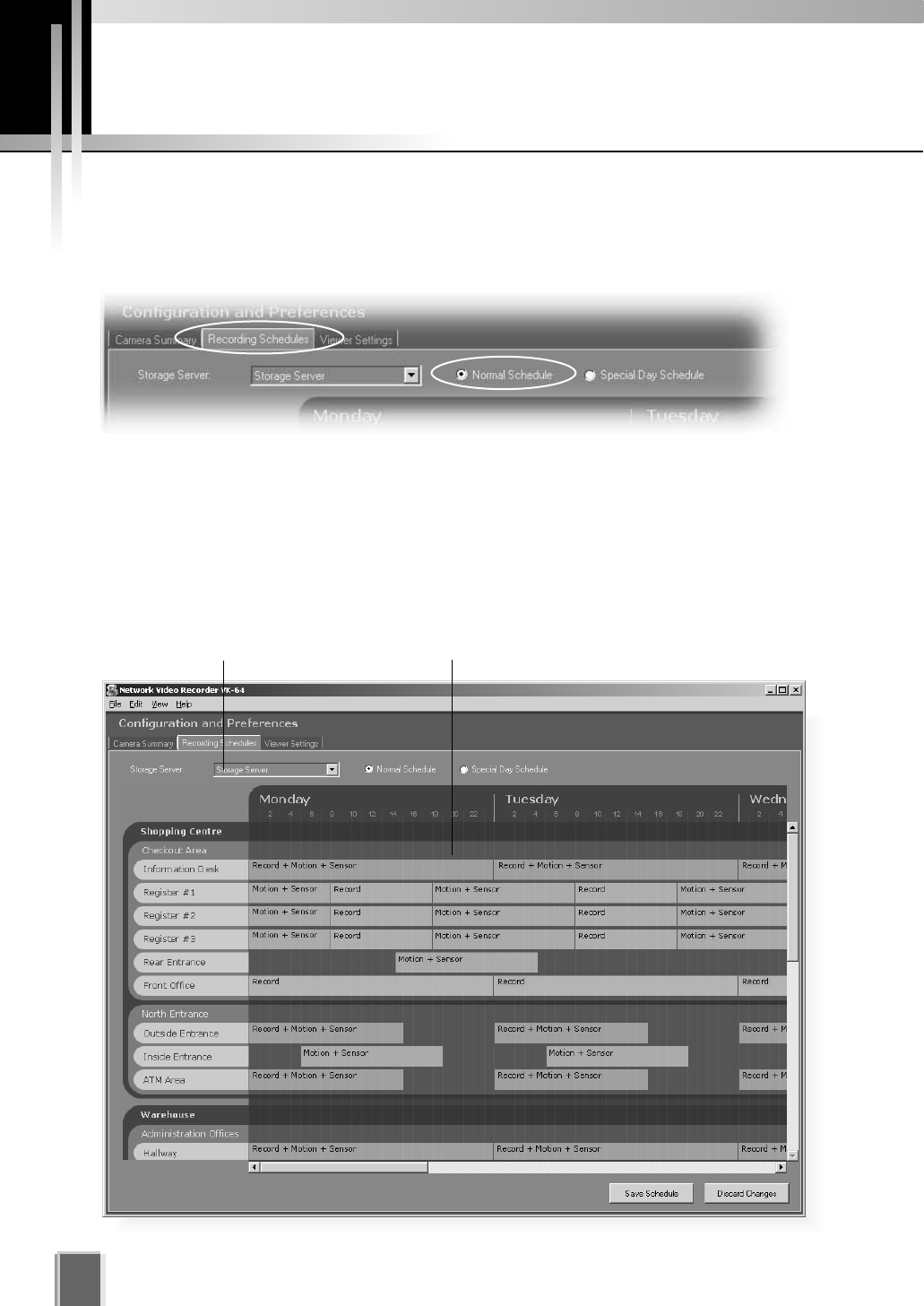
Configure Normal Recording
62
About the Recording Schedules window - Normal Recording
The Recording Schedules window is used for configuring recording settings for each known
Camera Server on the network.
In the Configuration and Preferences Screen, click the Recording Schedules tab and
ensure the Normal Schedule radio button is set. The Normal Recording Schedule
consists of:
Storage Server drop-down menu - Used to select which Storage Server schedule to
edit. When the Recording Schedules window is first opened, the first Storage Server
in the list is shown with its associated schedule to the right.
Schedule Area - Used to set up standard day-to-day recording settings of the system.
Storage Server selector Schedule Area
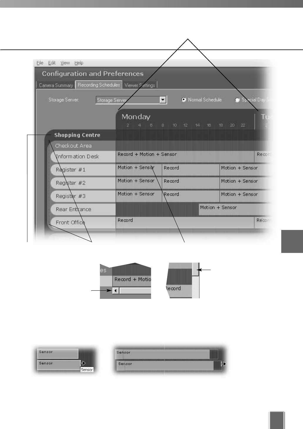
63
6
Configuring Recording Schedules
Time Scale for schedules
Click and drag the
vertical scroll-bar
downward to view
any other zones.
Click and drag the
horizontal scroll-bar
to the right to view
other schedule days.
Zones representing
camera areas
Location Camera schedule
time bars
Selecting multiple items and dragging or moving
While holding down the Ctrl key, click on individual schedule items to select them. You
can adjust or move multiple schedule items to new positions.
Drag either end to adjust duration (an arrow displays as shown above); or place mouse
over schedule item (a hand icon appears) and drag items to a new location.
You can also create multiple camera schedules. This is discussed on the following page.
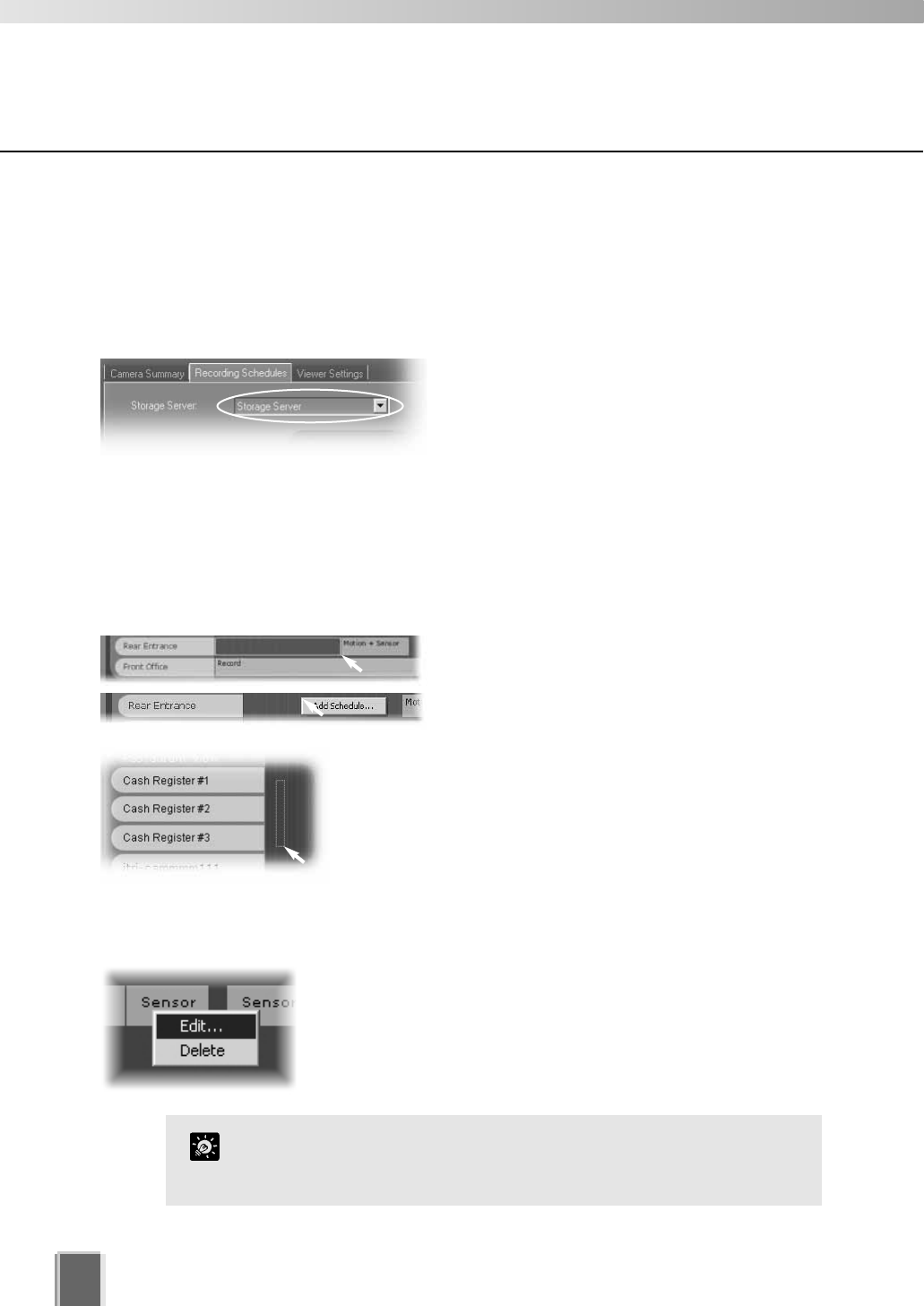
Configure Normal Recording
64
Create, Edit and Delete Recording Schedule Items
To add or edit a schedule for a camera in a zone, you need to launch the Add Schedule
Item or Edit Schedule Item dialog respectively.
Step 1: Change Storage Server if necessary
If you wish to display another Storage Server’s
schedule, click the Storage Server menu,
otherwise proceed to Step 2.
The menu may list more assigned Storage Servers. If you select another Storage Server,
the Schedule Area will refresh and associated schedule zones will be shown.
Step 2: Click in the schedule area and drag out a time period
Click and drag a time period for a camera name and release the mouse button.
Alternatively, right-click anywhere in the
Schedule Area alongside a camera name and
click Add Schedule from the context menu.
The Add Schedule Item dialog appears as
shown on the following page.
You can also click and drag an area covering several
cameras to bring up the Add Schedule Item - multiple
cameras dialog. This allows you to easily set schedules for
multiple cameras. Once created, settings for each camera
can be customized.
To edit a recording schedule item:
Right-click an item and choose Edit from the context menu.
Alternatively, double-click an item. The Edit Schedule Item
dialog appears.
Both the Add and Edit dialogs are identical as shown on the
following page.
To edit the time only, simply click an existing schedule item and
drag the right or left boundary to lengthen or shorten the time
respectively.
Tip
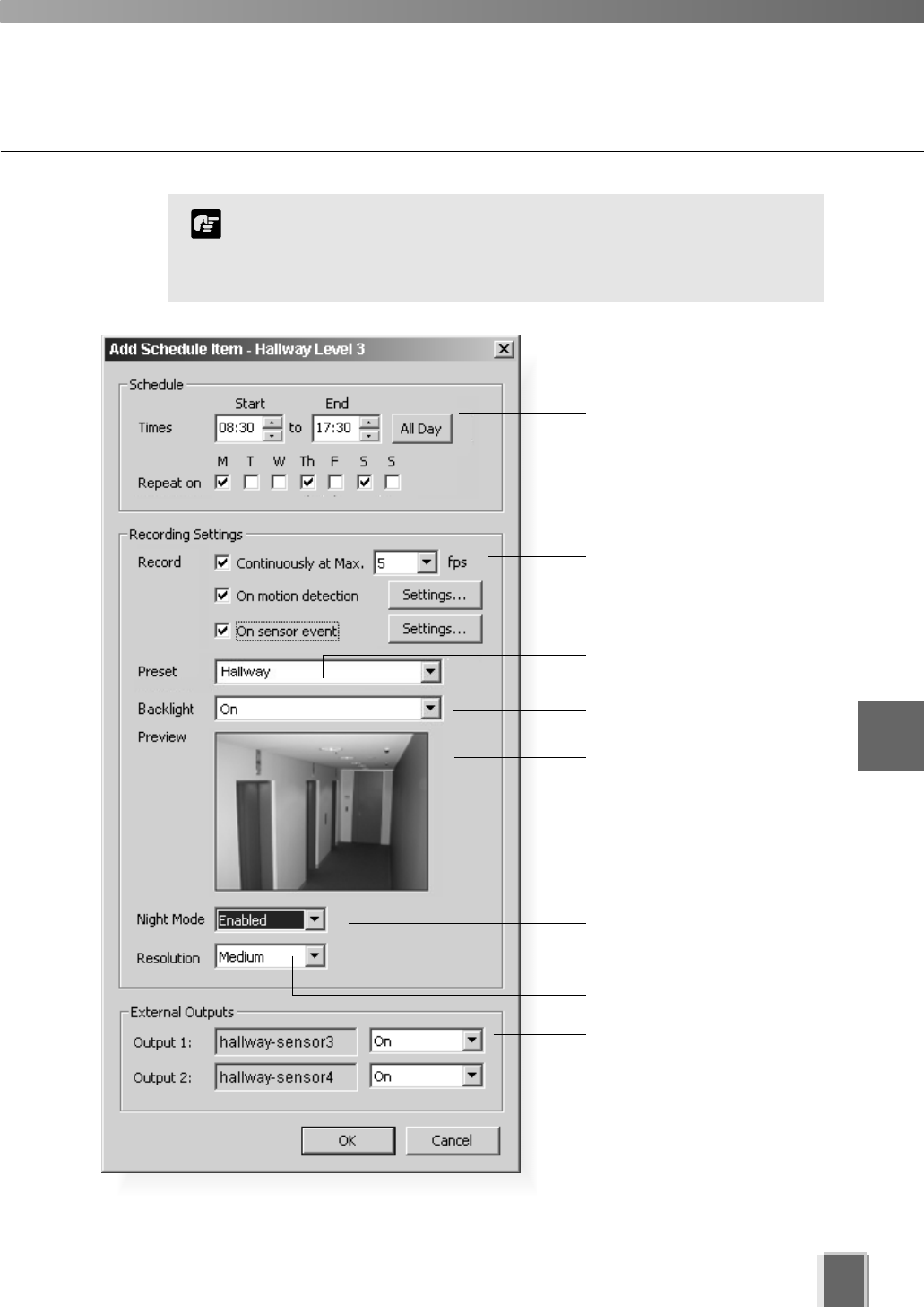
The minimum duration for a schedule item is 15 minutes. If you
try to create a shorter schedule, an error message will appear.
You cannot create overlapping schedule items.
Note
Configure Normal Recording
65
Set start and end times for one
or more days.
Set backlight compensation.
Preview area. Camera angle
can be changed by moving
your mouse pointer in the
Preview area to display
controls and clicking to pan,
tilt and zoom (tP. 56).
Select a camera angle for
recording.
Set recording resolution.
Set External Outputs to On or
Not Specified. This applies to
the duration of the schedule
item.
Set Night Mode (VB-C50i,
VB-C50iR, VB-C50FSi,
VB-C50Fi and VB150 only).
Configuration is discussed on the following pages.
Set frame rate, enable motion
detection and sensor event
recording.
6
Configuring Recording Schedules
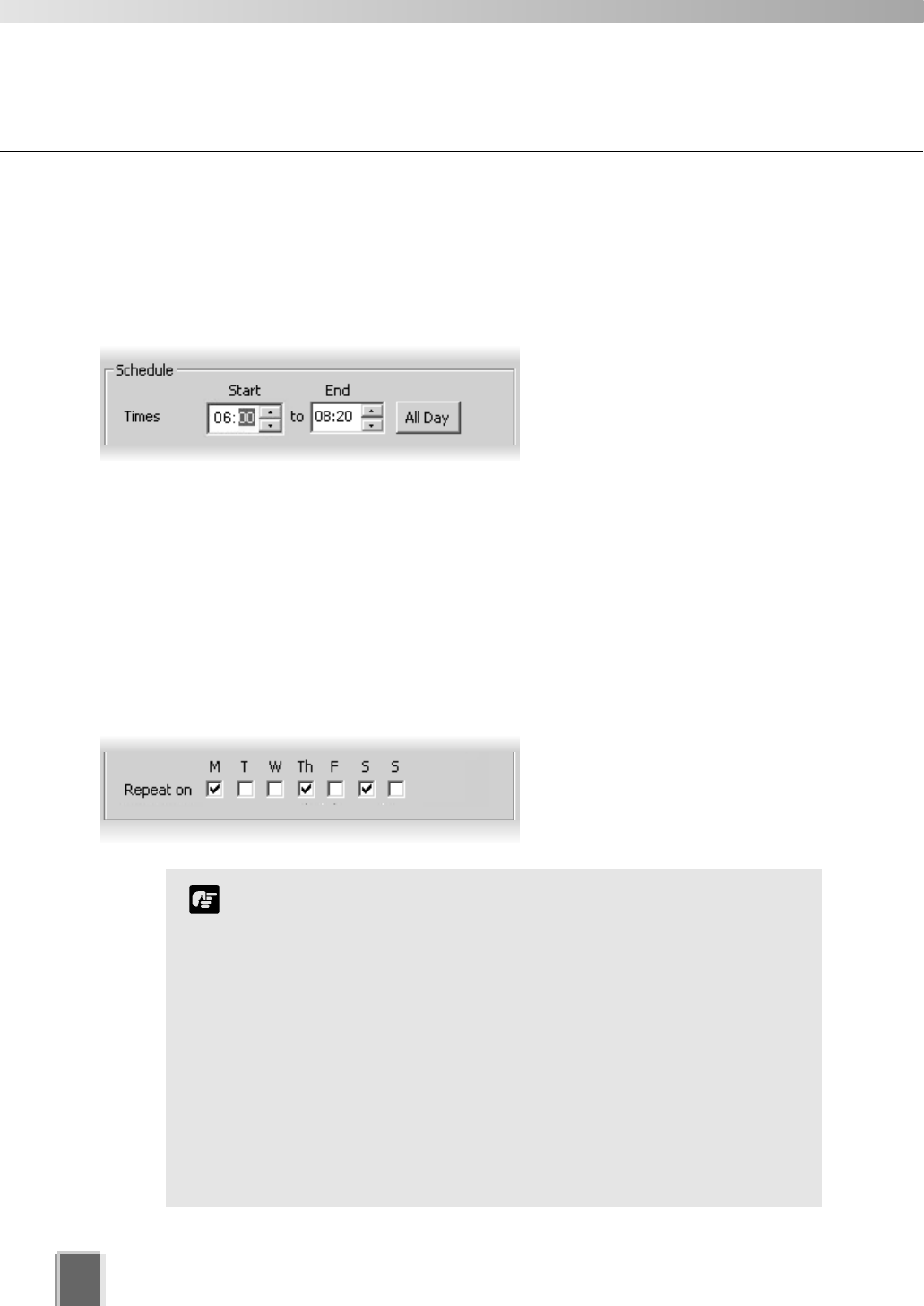
66
Configure Normal Recording
Add/Edit Schedule Item dialog - Schedule field
To set the schedule for a camera’s recording period:
Step 1: Set the recording period in the Start and End boxes
Click the hours or minutes fields to
select, then click the up/down
arrows to change time.
Alternatively, type over highlighted time with new time, or use the up/down arrows on your
keyboard to change the selected time. Use the left or right arrows on your keyboard to
move between minutes and hours and the tab button to jump to the next field.
An example time period could be for overnight recording such as ‘Start: 22:00 to End 08:00’.
Alternatively, click the All Day button if you want 24 hour recording. The Start and End
times will be set at 00:00 and 00:00 respectively.
Step 2: Select the days for recording
In the Repeat on area, tick the days
you wish to repeat the recording
period you set in the Times area
above.
If you have defined any special day schedules, such as public
holidays, such schedules will override normal schedule times
for the whole day.
Times are given in 24 hours, for example 18:00 is 6:00 pm.
A schedule item cannot be more than 24 hours.
If a Camera Server has been configured with ‘Restrict Service
Time’, VK-64 will not be able to record from the Camera Server
during restricted times.
The time zone used for the recording schedule will be the time
zone configured on the Storage Server.
The Storage Server will adjust for Daylight Savings if configured
in the operating system.
Note
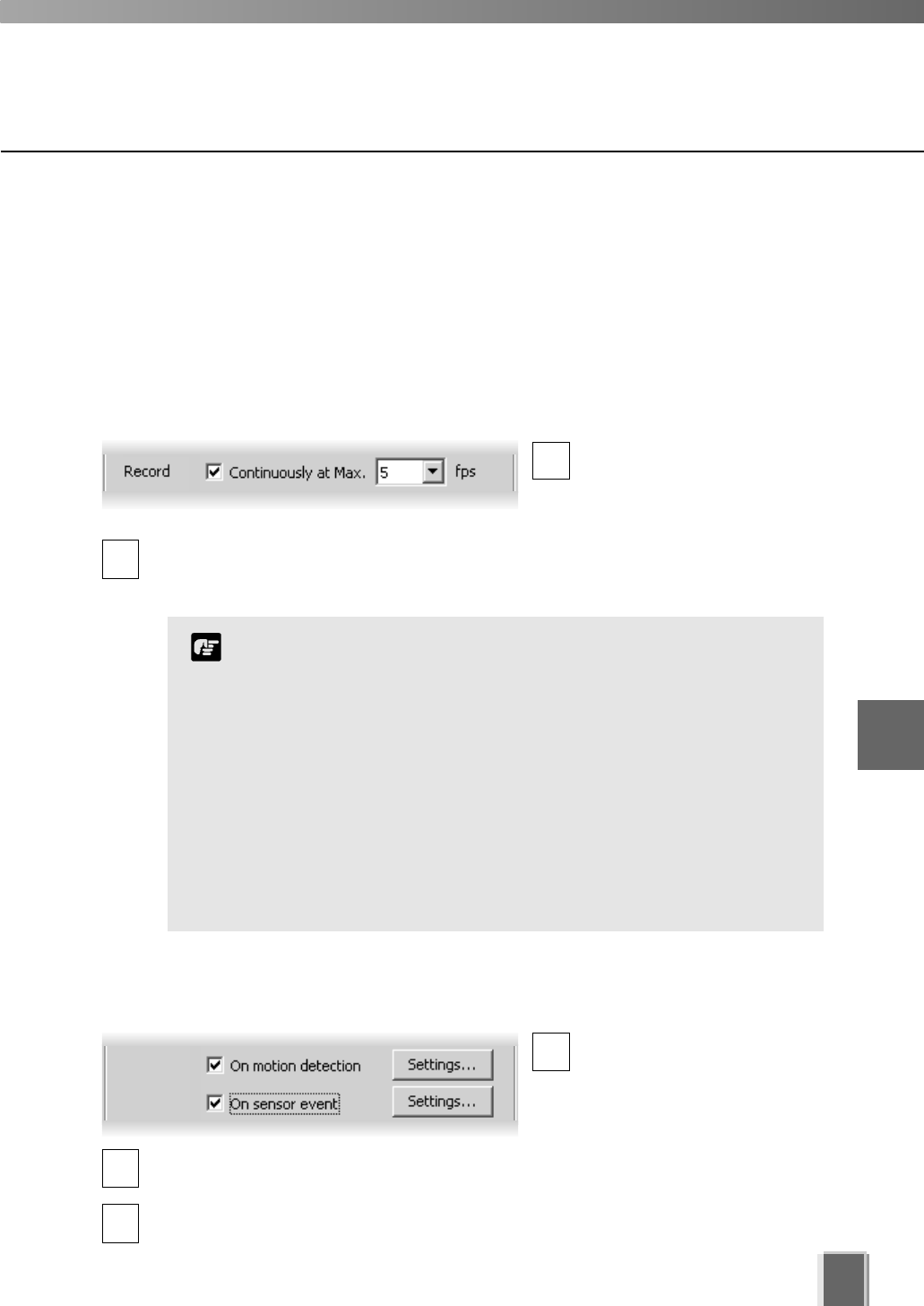
67
Configure Normal Recording
Add/Edit Schedule Item dialog - Recording Settings field
This section of the dialog allows you to set flexible parameters for recording. You can record
a Camera Server continuously at 1 frame per second and, for example, set recording to
increase to 30 frames per second when motion occurs. This allows efficient use of disk
space while allowing higher frame rates when events occur.
To set the camera’s recording parameters:
Step 1: Set the recording frames per second
Click the Continuously at
max box if you want to set
continuous recording for the
duration of the time period.
Select the number of frames per second from the drop-down menu, from 0.1 to 30. 5
frames per second is the default. Alternatively, enter a custom setting by selecting and
typing over the current setting.
2
Step 2: Optional: Select recording based on a motion or sensor event
Click the On motion
detection box if you want
recording activated when
motion is detected during this
time period.
Click the On sensor event box if you want recording activated from a sensor during
this time period.
Click the Settings... button to modify the settings for each of these functions, other-
wise the previous or default settings will apply.
1
When the load on your computer CPU and hard disk is high,
recording at the specified frame rate may not be available, or
the video recording may be interrupted.
When selecting a higher frame rate, make sure you have
enough hard disk space for your recorded video. Higher
frame rates result in larger file sizes (see Appendix B).
The frame rate specified is the frame rate that the Storage
Server will attempt to record. Factors such as the number of
Viewers, network traffic and load on the Camera Server and the
Storage Server may reduce the actual frame rate recorded.
Also, the maximum frame rate for a VB-C10 configured with
a resolution of 640 x 480 is 10 frames per second, and for a
VB150 with 4 cameras is 2-3 frames per second.
Note
1
2
3
6
Configuring Recording Schedules
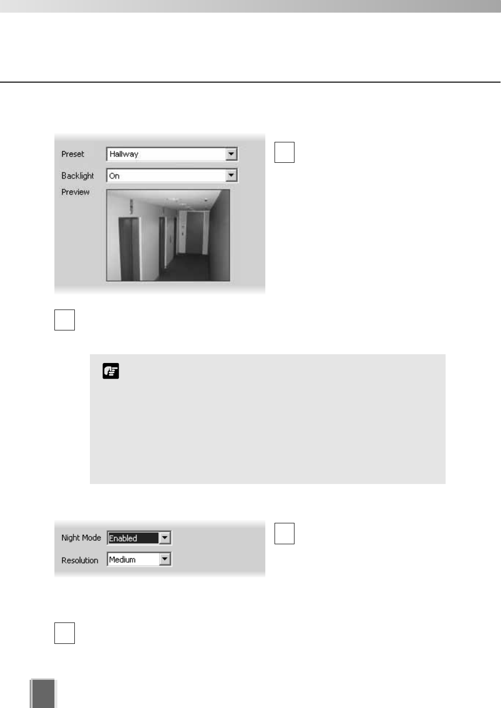
Configure Normal Recording
68
Step 4: Set the resolution and night mode (VB-C50i/VB-C50iR,
VB-C50FSi and VB-C50Fi)
Select the Night Mode
(tP. 76) from the drop-down
menu. Options include Enabled,
Disabled or Not specified.
If you select Enabled, the Night Mode status will be changed to Disabled after the
configured recording schedule finishes.
Select a Resolution from the drop-down menu; Low, Medium, High or Not
specified.
If you select Not specified, the Storage Server does not attempt to change the
setting, rather it accepts whatever resolution/mode the camera server offers.
Step 3: Choose a preset angle and adjust backlight compensation
In the Preview field a live
preview is given of the selected
camera view when connected.
Select a Preset camera position
from the drop-down menu of
available camera angles, to retain
a live preview from that angle.
Alternatively, move your mouse
pointer in the Preview area to
display controls and clicking to
pan, tilt and zoom (tP. 56).
Click the Backlight compensation drop down menu to set the backlight
compensation to On or Off (or High, Medium, Low or Off for VB-C50i/VB-C50iR,
VB-C50FSi and VB-C50Fi). Selecting Not Specified accepts whatever backlighting
the camera server offers.
1
1
2
2
You can also adjust the camera angle by moving your mouse
pointer in the Preview area to display controls. Click to pan, tilt
and zoom (tP. 56).
After the camera has been controlled, the preset will be set to
‘Custom’. The value this is set to will be the value used for
recording and the position set will be the position recorded.
If you select ‘Not Specified’ the Storage Server does not attempt
to change the setting, rather it accepts whatever
resolution/mode the camera server offers.
Note
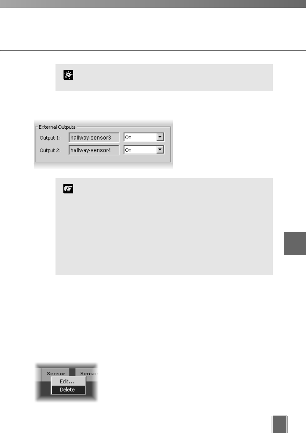
When you have finished, click OK to keep new settings or click Cancel to delete
modifications. The dialog will close.
When you click OK, the Preset and Backlight settings are effective on Video Windows in
the Viewer. If you are not satisfied with the settings, adjust them from the Viewer.
If you have not finished, proceed to the following pages which outline the dialogs used for
Sensor Event and Motion Detection recording.
Configure Normal Recording
69
When selecting a higher resolution, make sure you have
enough hard disk space for your recorded video. A higher
setting results in larger file sizes.
Camera servers have certain features to allow image capture
operations based on sensor input or schedule. If settings are
enabled on the Camera Server, they take precedence over any
settings made in VK-64. This may cause some confusion if your
VK-64 recording schedules fail to record with the correct
camera preset. You should disable such Camera Server
features if you wish VK-64 settings to take precedence. Refer to
your camera server manual for more information on their
settings.
Note
Step 5: Set the External Outputs
If outputs are available, click the
drop-down menu to set them On or
Not Specified.
To delete a schedule item:
Right-click an item and choose Delete from the context menu.
Alternatively, click an item to select it and choose Delete from
the Edit menu.
Alternatively, click an item to select it, and then press the Delete
key on your keyboard.
6
Configuring Recording Schedules
You can also configure the Night Mode setting if you use a
VC-C50i/VC-C50iR connected to a VB150.
Tip
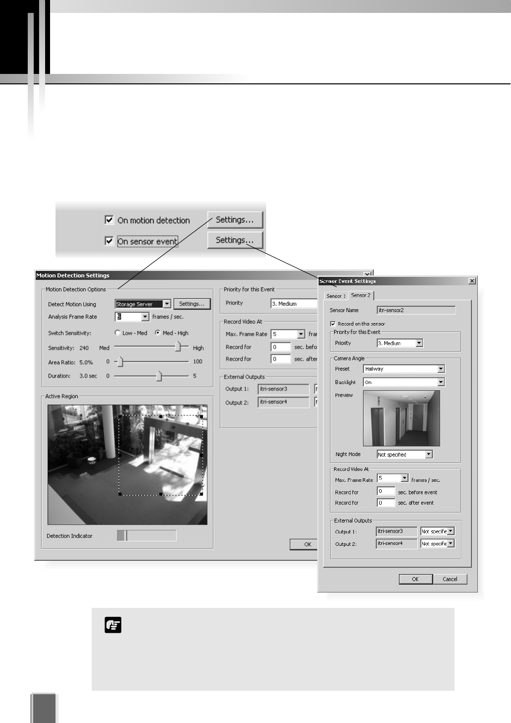
Configure Motion and Sensor Settings
70
Recording Schedule dialog - Motion and Sensor Settings
In the Add/Edit Recording Schedule dialog, there are two options available for setting
recording parameters. To enable recording options and adjust settings:
Tick one or both boxes and click the Settings... button
Tick each box to enable the functions.
Default settings are then enabled.
Click Settings... to change the default
settings for each option.
c
The motion detection settings are dependent on the quality
settings of the Camera Server. When setting motion detection
parameters, it should be ensured that the quality setting of the
Camera Server is the same as the quality setting that will be in
place at the time that the schedule item applies. Refer to your VB
manual.
Note
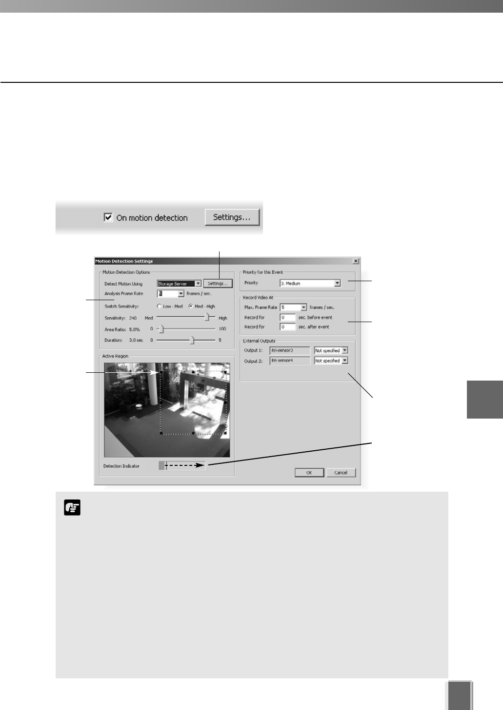
71
6
Configuring Recording Schedules
Recording Schedule - Edit Motion Detection Settings
You can specify recording based on motion detection and the amount of sensitivity can be
adjusted. The area for detection can also be modified which is ideal, for example, if the field
of view has two entrances and you wish to monitor motion for one entrance.
Click and
drag a
control point
to re-size
the active
region.
Motion detection
level indicator will
increase during
activity.
Click to activate motion detection on the camera server for VB-C50i/VB-C50iR, VB-C50FSi and VB-C50Fi (tP. 75).
Select
sensitivity
options.
The Motion Detection Settings dialog
opens (VB-C50i dialog shown below).
Step 1: Next to ‘On motion detection’, click the Settings... button
Select frame rate
and pre/post
event duration for
recording triggered
by motion.
Activate external
outputs.
Set a priority for
events triggered
by motion.
The Motion Detection function is not suited to applications
where high levels of reliability are demanded. Therefore, we
recommend that you do not use this function for monitoring or
other purposes if consistently high levels of reliability are
required. Canon accepts no liability whatsoever for faults, etc.
resulting from the use of the Motion Detection function.
If continuous and motion detection recording are both set and pre event
recording is configured, pre event recording will be at the continuous
frame rate setting instead of the motion event frame rate setting.
If the Picture Recording feature of a Camera Server is used and its
configuration includes a preset position then this preset position will
override camera positions set by VK-64, including those in recording
schedules and the Viewing Screen. If VK-64 has camera control, this will
be lost when the Camera Server is setting a new preset position.
Note
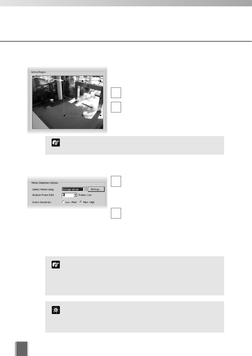
Configure Motion and Sensor Settings
72
In the Detect Motion Using menu, select the
detection method, Camera Server or Storage
Server. This menu is only active for VB150
servers with the Video Input set to Single or VB-
C50i/VB-C50iR, VB-C50FSi and VB-C50Fi.
In the Analysis Frame Rate menu, select
from 0.1 to 30 frames per second.
The Settings... option is available for VB-C50i, VB-C50iR, VB-C50FSi and VB-C50Fi
cameras. Select Camera Server from the drop-down menu and a message box about motion
detection is displayed. Click OK to continue. The Settings... button is now enabled. Click to
launch your VBAdmin Motion Detection Setting Tool. You must have VBAdmin Tools version
2.0 or later. See page 75 for important information on camera server-based motion detection.
Step 3: Set Motion Detection Options
1
2
The Analysis Frame Rate refers to how many frames per second are
used for detecting motion. A lower value will decrease the
processing load on the server and allow more Camera Servers to
have motion detection.
Tip
In the Active Region field, adjust the region where
motion detection is triggered. By default, the Active
Region is the full area.
Click one of the corner or edge handles and
hold down the mouse button.
Drag the handle to change the motion-trigger
boundary (dotted frame); click the corners to
adjust the area or click the edge handles to
bring each side in or out respectively.
1
2
You cannot control camera Pan, Tilt or Zoom from this window.
Note
Step 2: Set the active region for recording
To use the motion detection function of the VB-C50i/VB-C50iR,
VB-C50FSi and VB-C50Fi, it is necessary to configure
schedules from the ‘VBAdmin Schedule Setting Tool’.
If motion detection is performed on a VB150, detection can only
be achieved on one of its cameras within a schedule item.
Note
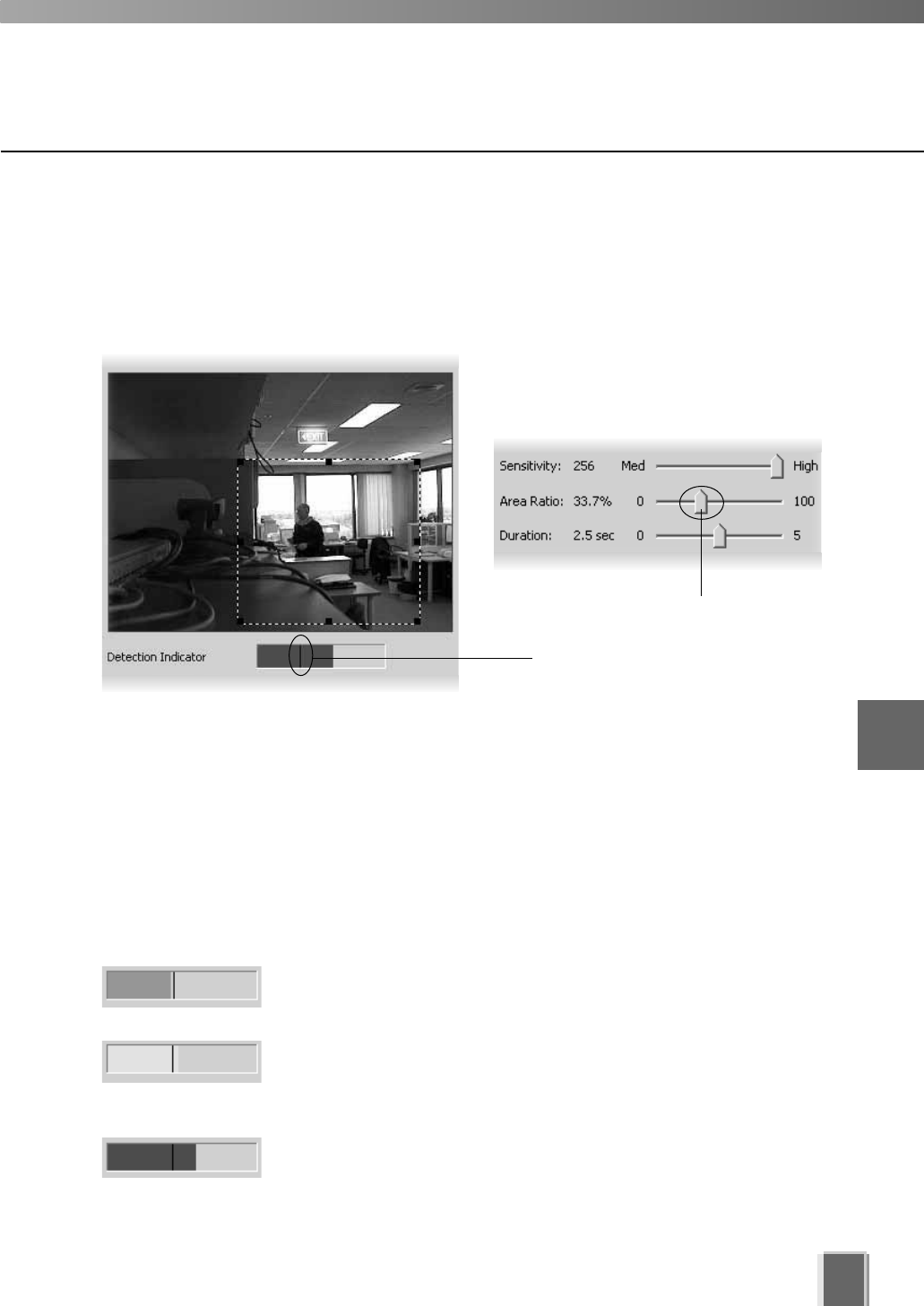
Detection Indicator Colors
Motion is displayed in the Detection Indicator as a green color bar and will remain green if
the level of motion is below the set Sensitivity and within a defined Area Ratio. If motion
reaches the set Sensitivity and Area Ratio, the color bar changes to yellow and if the
detected motion remains at the yellow level for the defined duration, a red color bar is
displayed and an event is triggered. The behaviour of the Detection Indicator is described
as follows.
Green color bar - The area of change that is less than the
specified Area Ratio, i.e., activity remains at the left of the Area
Ratio marker.
Yellow color bar - The area of change that is equal to or
greater than the specified Area Ratio (activity peaks on or to the
right of the Area Ratio marker) but the required amount of motion
has not met the specified duration in order to trigger an event.
Red color bar - The amount of change that meets the
defined detection conditions and motion is detected,
triggering an event, i.e., the required amount of motion
has been detected for the specified duration.
Configure Motion and Sensor Settings
73
Area Ratio marker.
You can set the amount of motion required before the red color bar is displayed, while
monitoring the image here.
Area Ratio slide bar.
The Motion Detection Options field also allows you to set the sensitivity for motion
detection within the Active Region. There are three controls, Sensitivity, Area Ratio and
Duration. Settings for these determine how great the variation of motion detection will be,
how large the changed area will be (a proportion of the detection area set) and how long
the variation will continue before it is recognized as motion and the event is triggered.
The adjustment for the Area Ratio is indicated in the Detection Indicator as shown below.
6
Configuring Recording Schedules
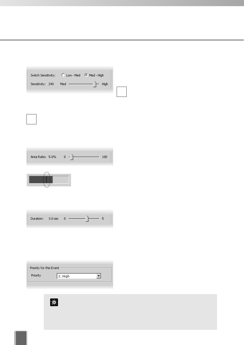
74
Configure Motion and Sensor Settings
If continuous and motion detection recording are both set and the
frame rate is the same, motion will be recorded as events in the
usual way. This can be handy for follow-up browsing using the
Timeline in the Viewing Screen even though the motion does not
change the recording settings.
Tip
Set the Sensitivity
The available sensitivity settings range from 1 to
256. You can select either Low-Med or Med
High sensitivity ranges for finer control.
Click the Low radio button to set the
sensitivity range from 1 to 128, or,
Click the High radio button to set the
sensitivity range from 129 to 256.
Adjust Sensitivity by clicking and dragging the slide bar to a suitable level between
Low and Med, or Med and High (depending on the range setting).
1
2
Set the Area Ratio
Click and drag the Area Ratio slide bar to any
position from 0% to 100%. This establishes the
proportion of image inside the Active Region
(dotted frame) allowed before motion is detected.
When you drag the slide bar, the black vertical line in the Detection
Indicator will move to reflect the change in specified Area Ratio.
Set the Duration
Click and drag the Duration slide bar to any
position between 0.0 and 5.0 seconds. This
establishes the duration of motion allowed
before an event is triggered. It also establishes
the period where there is no motion in order for the event to be completed.
Step 4: Set the event priority status
In the Priority for this Event field, select the
priority for the event to be generated for this
motion from a menu of five options, ranging
from 1. Highest to 5. Lowest. Priorities are
color-coded as events in the Timeline.
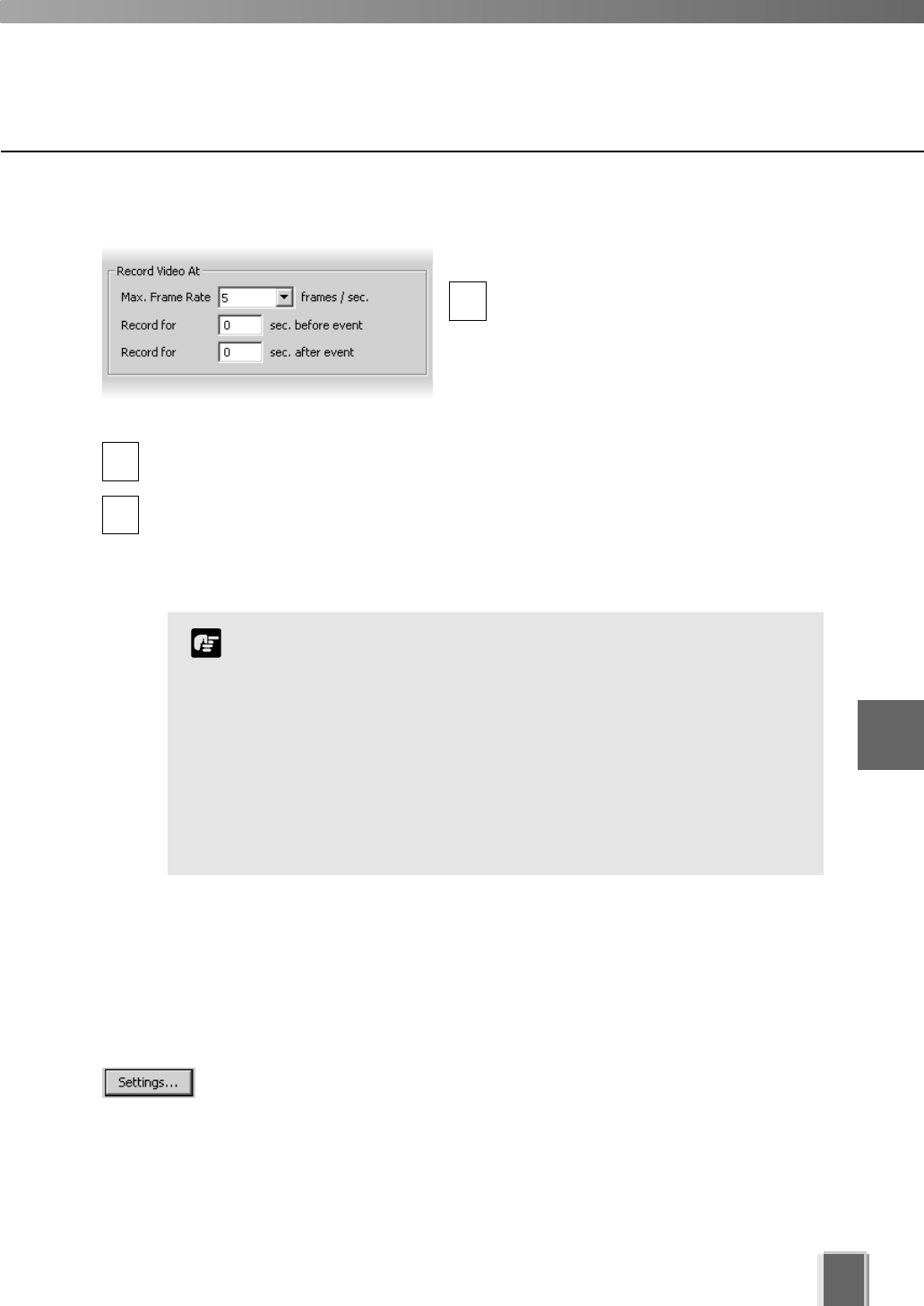
75
Configure Motion and Sensor Settings
Step 5: Set frame rate and pre and post event recording duration
In the Record Video At field:
Max. Frame Rate - select a maximum
frame rate for recorded video from the
drop-down menu. Choose from 0.1
frames per second to 30 frames per
second (5 is the default). Alternatively,
select the current rate and overwrite with
a custom rate.
Record for before event - enter a number of seconds for the amount of recording time
before the event occurs (up to a maximum of 30 seconds).
Record for after event - enter a number of seconds for the amount of recording time
after the event has transpired (up to a maximum of 999 seconds).
When settings have been modified, click OK to keep new settings or Cancel to delete
modifications. When either button is selected, the dialog will close.
1
2
3
If the before event and after event fields are set to 0
seconds, video will still be recorded while motion is detected.
Shorter pre event recording will reduce memory usage. Longer
pre-event recording with insufficient memory may lead to the
use of disk-based virtual memory which will greatly reduce
performance.
The full requested duration of post event recording may not be
available. Frame rate, frame size and network delays may have
an effect on when the last frame is recorded and thus affect the
actual duration of the recording.
Note
6
Configuring Recording Schedules
About motion detection on different camera servers
When using motion detection on the camera server, the situation differs depending on the
type of camera server. For a VB150 (in single mode), motion detection settings are
configured using the normal VK-64 ‘Motion Detection Settings’ dialog. Here, changes to the
settings on the camera server are made at the time of the schedule item. These changes
continue to take effect after the schedule item is completed.
For a VB-C50i, VB-C50iR, VB-C50FSi and VB-C50Fi, the motion detection
settings are configured by pressing the Settings button. This launches the
camera server’s ‘Motion Detection Settings Tool’. This changes the current settings on the
camera server and does not associate these settings with the schedule item. For a
VB-C50i, VB-C50iR, VB-C50FSi and VB-C50Fi, it is possible to schedule different motion
detection settings at different times using the ‘Schedule Setting Tool’. It is also possible to
set up to four motion detection areas using the ‘Motion Detection Settings Tool’.
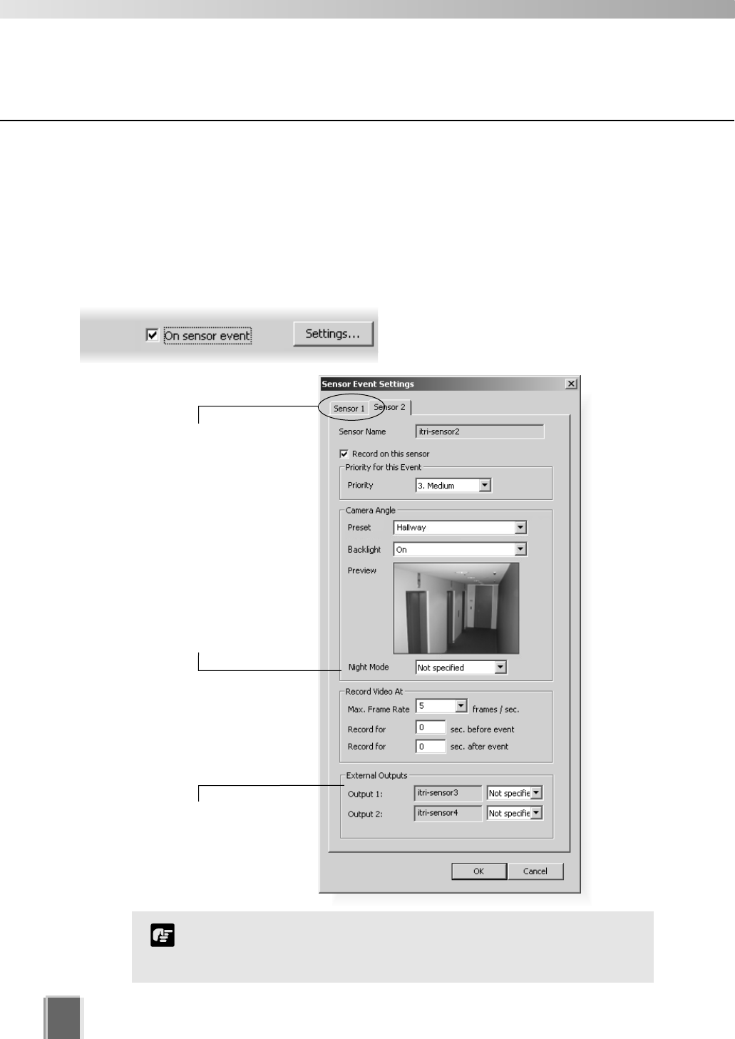
Configure Motion and Sensor Settings
76
Recording Schedule - Edit Sensor Events Settings
You can specify recording settings based on the occurrence of a sensor event. A number
of tabs in the Sensor Event Settings dialog are shown to reflect the number of sensors on
each camera. You can modify the recording settings for each sensor.
Step 1: Next to ‘On sensor event’, click the Settings... button
The Sensor Event Settings dialog
opens.
Click a tab to modify that
sensor’s settings. The
Sensor Name is indicated
below.
Night Mode is available for
VB-C50i/VB-C50iR, VB-C50FSi
and VB-C50Fi camera servers
or VC-C50i/VC-C50iR cameras
connected to camera server
VB150, allowing you to see
video in dark conditions. You
can choose to have it Enabled,
Disabled or Not specified.
External Outputs such as
light switches can be set to
On or Not specified.
Setting Night Mode to ‘Enabled’ will activate the IR cut filter on
camera servers that support it. It will not turn on the built-in IR light.
Note
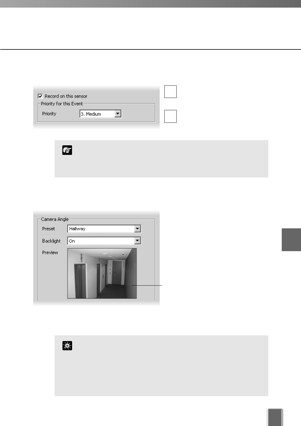
Configure Motion and Sensor Settings
77
Step 2: Enable recording and set an event priority
Tick Record on this sensor to
enable recording when a sensor is
triggered.
Select the event’s priority from a
drop-down list, from 1. Highest to
5. Lowest.
Step 3: Select a camera angle for the sensor
In the Camera Angle field, select a
Preset camera position from the
drop-down menu of available camera
angles. When the sensor is triggered,
the camera will be changed to this
position.
If you select Not Specified, the camera
will not be moved.
The camera angle can also be changed
by moving your mouse pointer in the
Preview area to display controls and
clicking to pan, tilt and zoom (tP. 56).
After the camera has been controlled,
the preset will be set to ‘Custom’.
You cannot modify the sensor name (identified as the ‘External
Device Input Name’ in the VB Camera Server configuration), which
is obtained from the Camera Server and therefore outside the
scope of VK-64 configuration.
Note
Click the Backlight drop-down menu and select ‘On’ to
compensate for camera views with strong backlighting*. The
setting will be used when the sensor is triggered. This is useful, for
example, if a camera angle would change from an indoor view to an
outdoor view when the sensor is triggered.
*If you are using a VB-C50i/VB-C50iR, VB-C50FSi and VB-C50Fi, the
backlight menu options are ‘High’, ‘Medium’, ‘Low’ and ‘Off’.
Tip
1
2
6
Configuring Recording Schedules
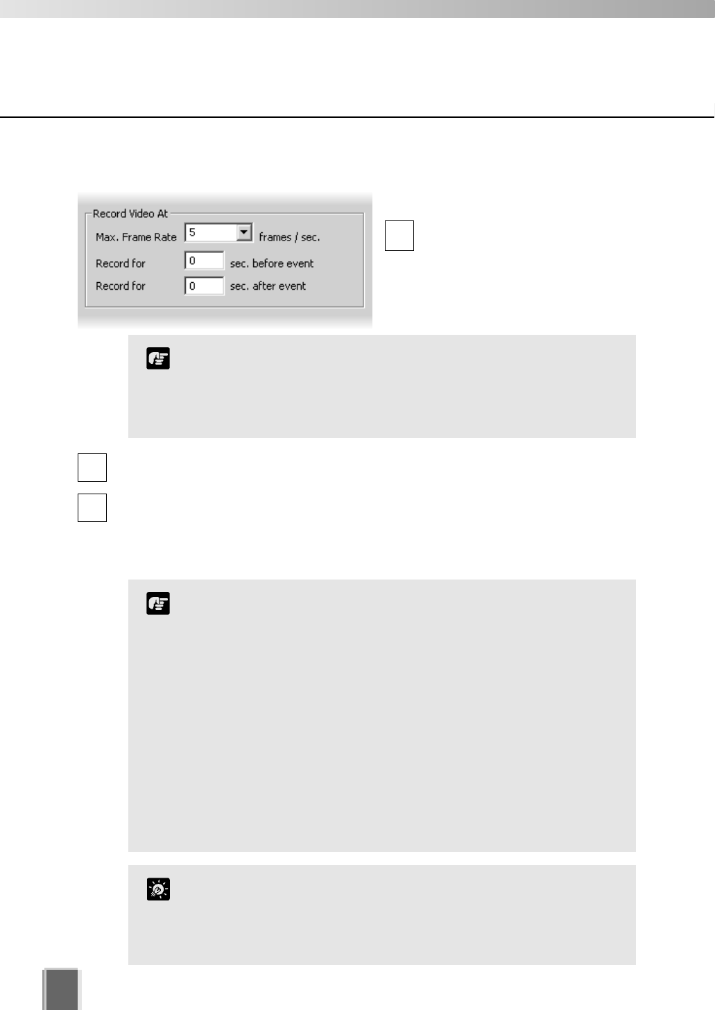
Step 4: Set frame rate and pre and post event recording duration
In the Record Video At field:
Max. Frame Rate - select a
maximum frame rate for recorded
video from the drop-down menu.
Choose from 0.1 frames per
second to 30 frames per second (5
is the default).
Record for sec. before event - enter a number of seconds for the amount of
recording time before the event occurs (up to a maximum of 30 seconds).
Record for sec. after event - enter a number of seconds for the amount of recording
time after the event has transpired (up to a maximum of 999 seconds).
When settings have been modified, click OK to keep new settings or Cancel to delete
modifications. When either button is selected, the dialog will close.
78
Configure Motion and Sensor Settings
1
2
3
The frame rate specified is the frame rate that the Storage
Server will attempt to record. Factors such as the number of
Viewers, the number of Camera Servers used, network traffic
and load on the Camera Server and the Storage Server may
reduce the actual frame rate recorded.
Note
If the before and after event fields are set to 0 seconds, video
will still be recorded while the sensor is activated.
Shorter pre event recording will reduce memory usage. Longer
pre-event recording with insufficient memory may lead to the
use of disk-based virtual memory which will greatly reduce
performance.
If continuous and sensor recording are both set and pre event
recording is configured, pre event recording will be at the
continuous frame rate setting instead of the sensor event frame
rate setting.
The full requested duration of post event recording may not be
available. Frame rate, frame size and network delays may have
an effect on when the last frame is recorded and thus affect the
actual duration of the recording.
Note
If continuous and sensor recording are both set and the frame rate
is the same, sensor events will be recorded as events in the usual
way. This can be handy for follow-up browsing using the Timeline
in the Viewing Screen even though the sensor does not change the
recording settings.
Tip
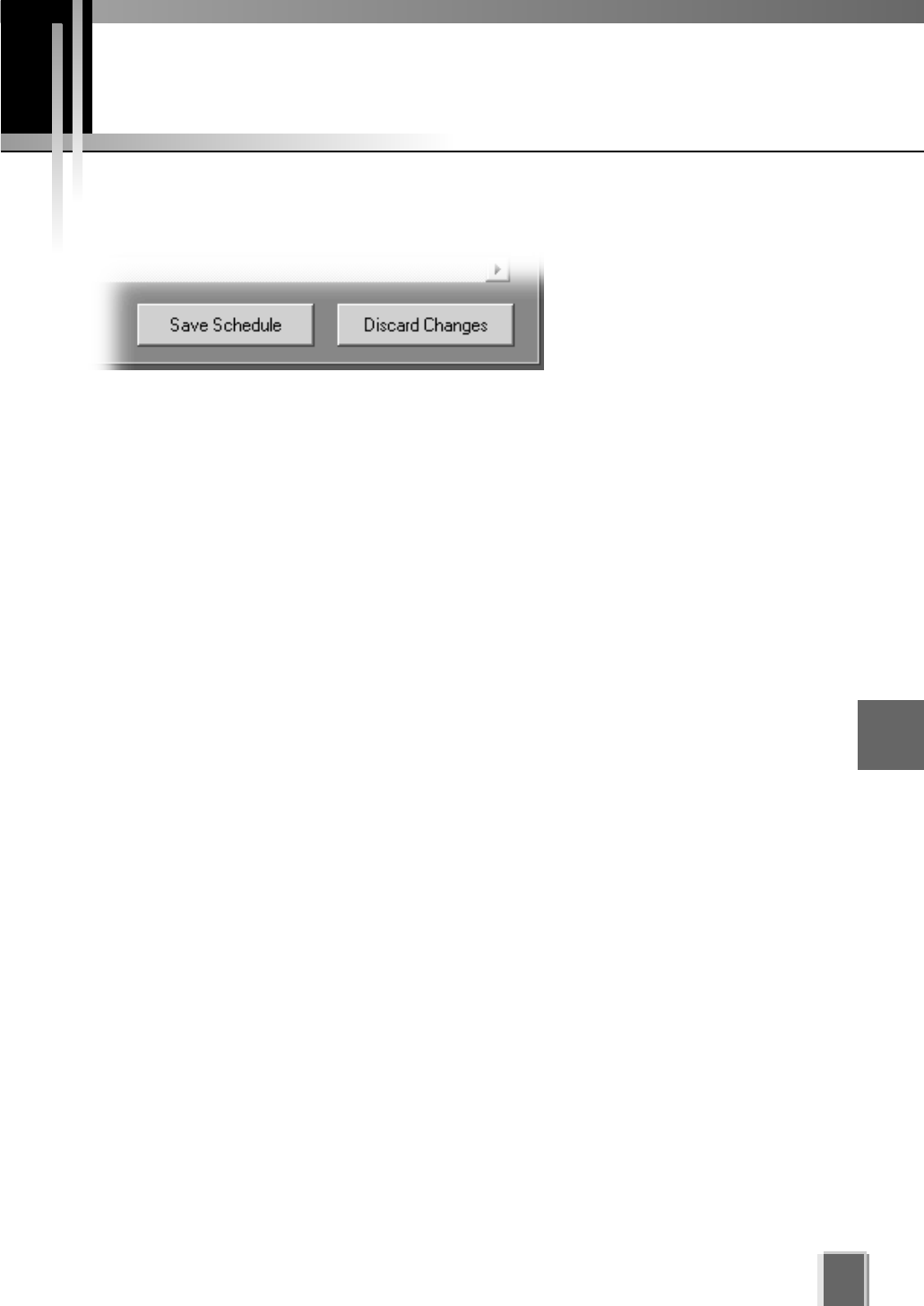
79
Saving Normal Recording Changes
When you have finished Normal Recording configuration...
The bottom right-hand corner
of the Recording Schedules
window consists of two buttons,
Save Schedule and Discard
Changes.
Click Save Schedule to keep all your settings. The settings are then saved to the
Storage Server.
Click Discard Changes to cancel any modifications you have made.
If you wish to return to the Viewing Screen, select View > Viewing Screen from the
menu bar.
6
Configuring Recording Schedules
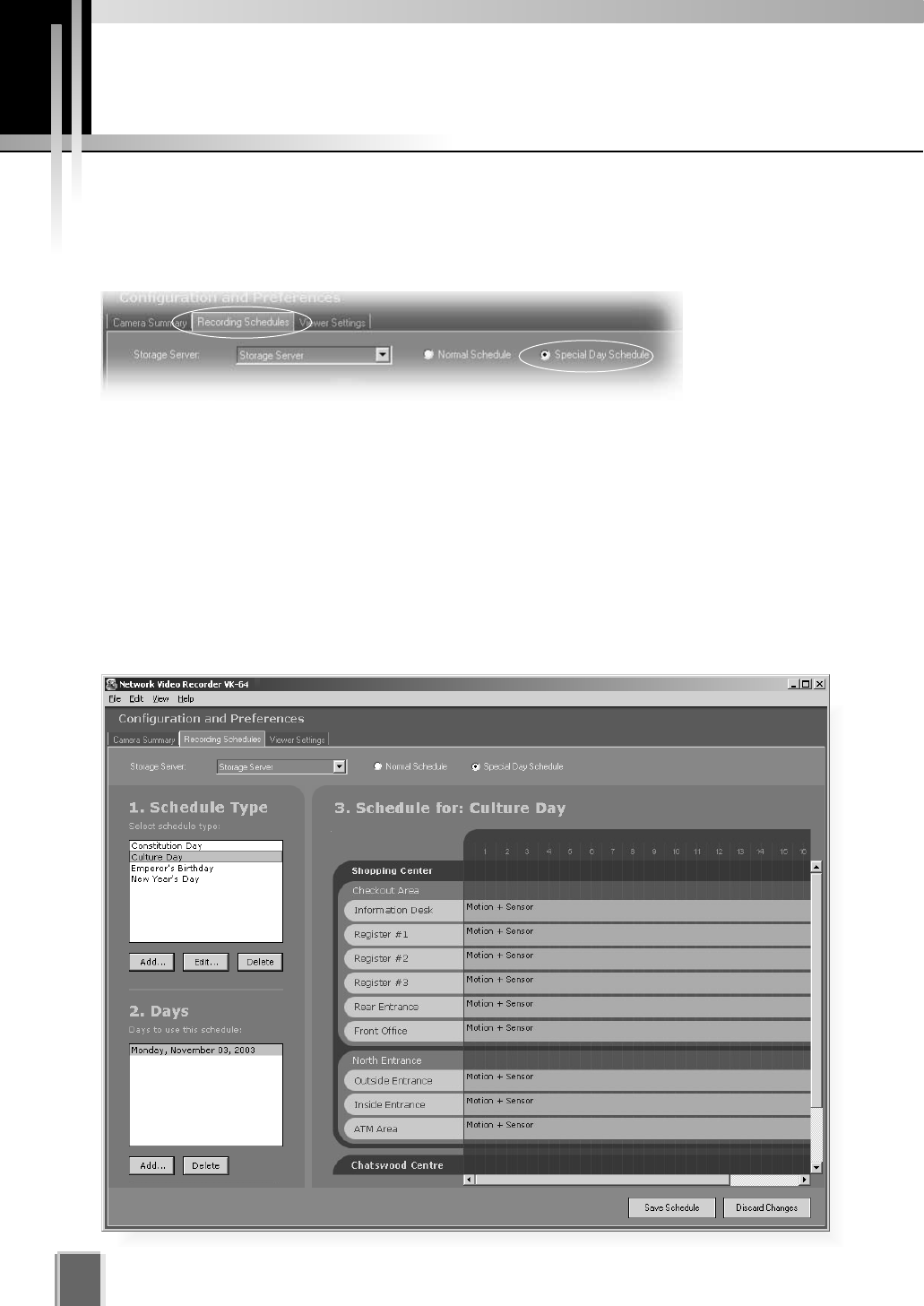
Configure Special Day Recording
80
About Special Day Recording
The Special Day Schedule window is used for configuring particular days such as public
holidays. Special Day schedules override any periods set in the Normal Schedule.
In the Configuration and Preferences Screen, click the Recording Schedules tab and
ensure the Special Day Schedule radio button is set. The Special Day Recording
Schedule consists of:
Storage Server - Select a Storage Server from the list to edit/add schedules for that
server. Associated Locations and Zones are displayed in the Schedule Area.
Schedule Type selector - Allows you to select a schedule type. These are
user-defined schedules such as Public Holidays and Long Weekends.
Days selector - Allows you to choose a day to use this schedule.
Schedule Area - Covers a single day, 24 hours. Overrides a Normal day schedule.
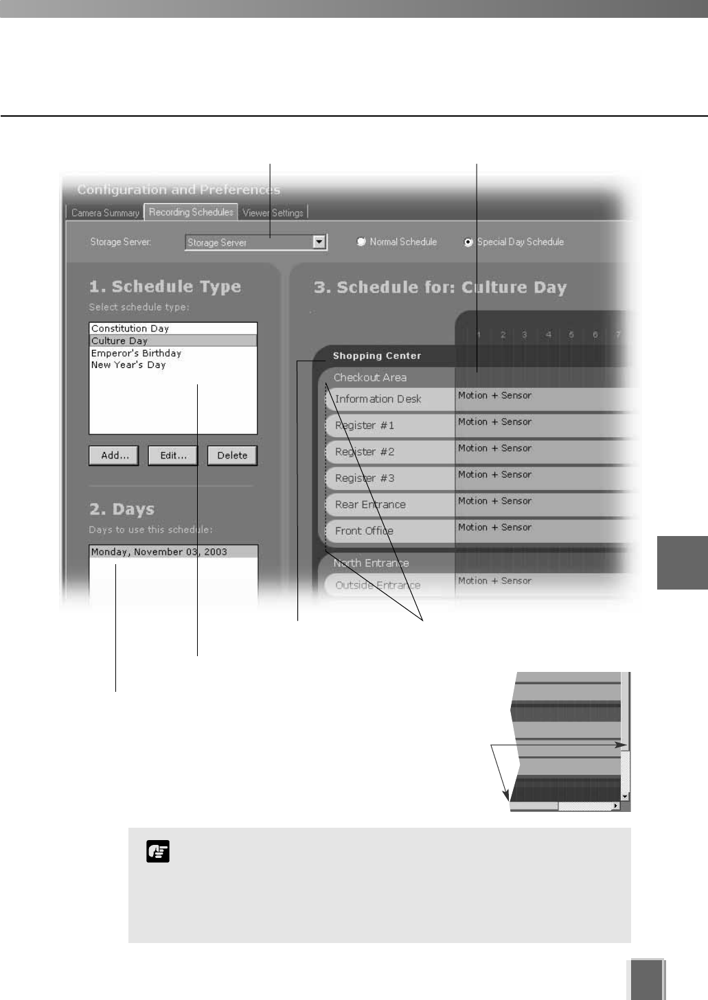
81
Storage Server selector Single day schedule area (24 hours)
Zone representing camera
areas in the Location
Location
Schedule Type selector
Day selector
The scheduling area functions the same as the Normal Recording
Schedule but only covers a single day. On a special day, this
schedule will override the Normal Recording Schedule from 00:00
hrs. to 24:00 hrs. To have a special day schedule run over a long
weekend (Fri, Sat & Sun), all three days must be added to the list
of days to use the schedule.
Note
Click and drag the
scroll-bar(s) to view more
schedules if necessary.
6
Configuring Recording Schedules
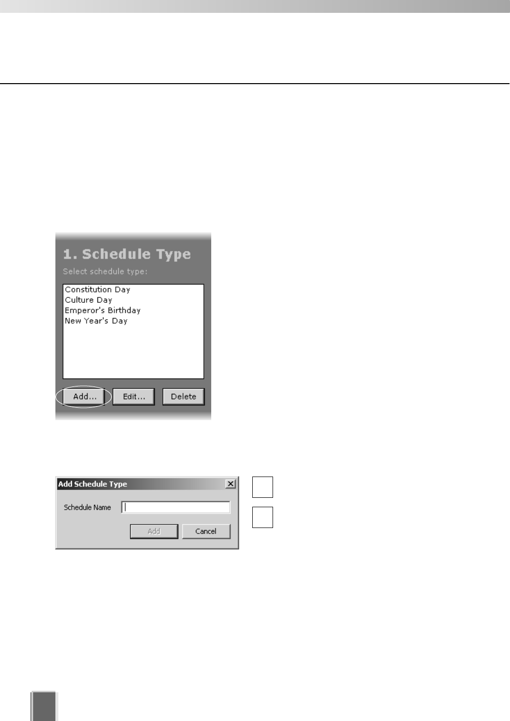
Configure Special Day Recording
82
Add and Edit a Schedule Type
The Add Schedule Type dialog allows you to create a name for a new schedule type, for
example, a public holiday. You must create a schedule type first before you can associate
days with it. There is no limit to the number of schedule types that can be added.
To launch the dialog and add a schedule type:
Step 1: Click the Add button below the Schedule Type list
Click the Add button. This will bring up the Add
Schedule Type dialog.
Step 2: Enter a name
Enter a name in the Schedule Name
area, for example ‘Company Holidays’.
Click the Add button to add the
schedule type. The dialog will close.
The new name will appear in the
Schedule Type list in the Special Day
Recording Schedule window.
2
1
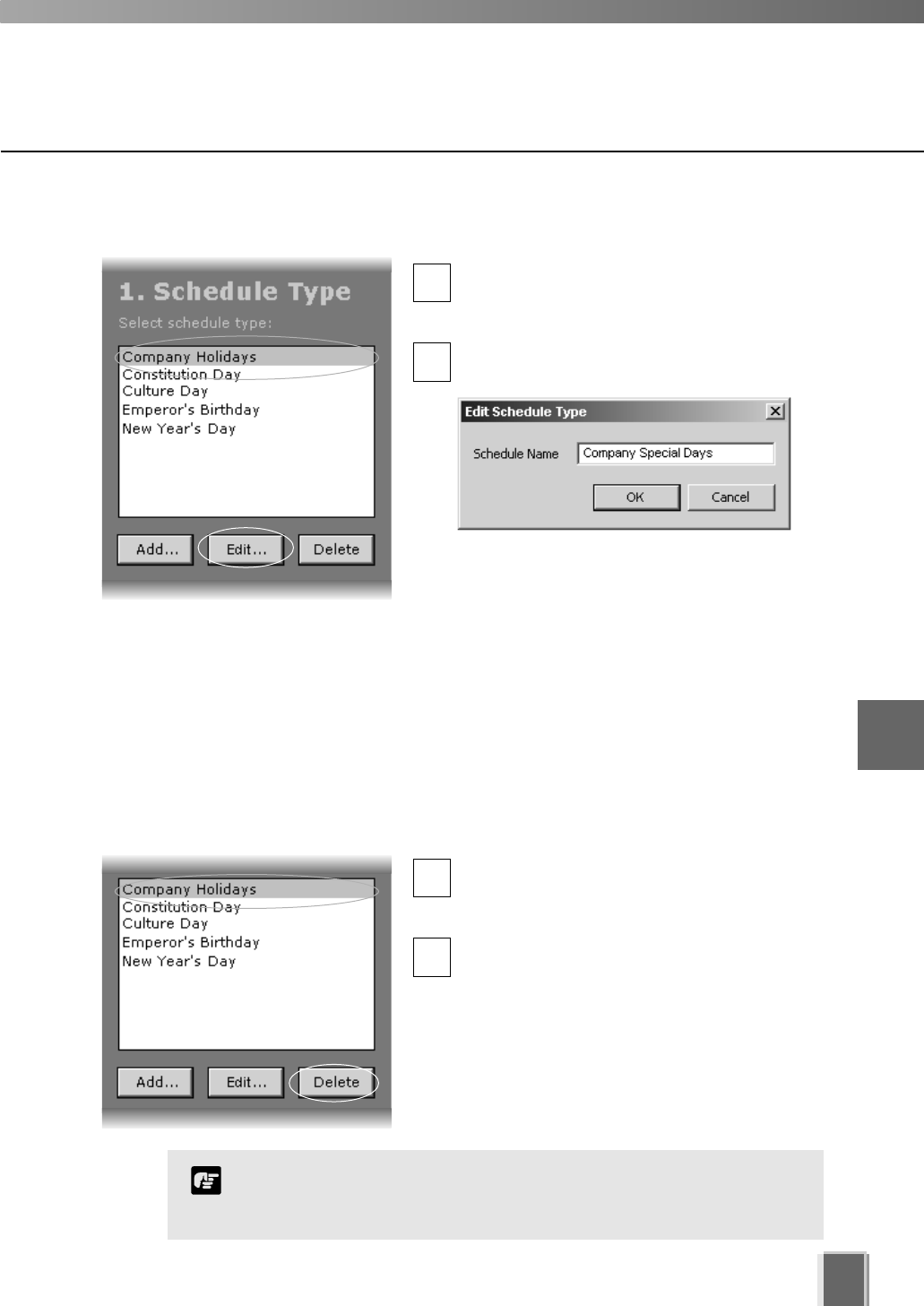
Configure Special Day Recording
83
Delete a Schedule Type
To delete a schedule type:
Select a Schedule Type and click the Delete button
ln the Special Day Schedule window, click a
schedule type in the Schedule Type list to
highlight it.
Click the Delete button below the list to
remove the schedule type.
To edit a schedule type, click the Edit button
ln the Special Day Schedule window, click a
schedule type in the Schedule Type list to
select it.
Click the Edit button. This will bring up the
Edit Schedule Type dialog.
Overwrite the existing name. For example,
you may wish to change the name ‘Company
Holidays’ to ‘Company Special Days’.
Click the OK button to save your changes.
The dialog will close.
2
1
2
1
If you delete a schedule type where there are dates associated with
that schedule, a warning will appear. You will be asked to first
delete those dates before deleting the schedule type.
Note
6
Configuring Recording Schedules
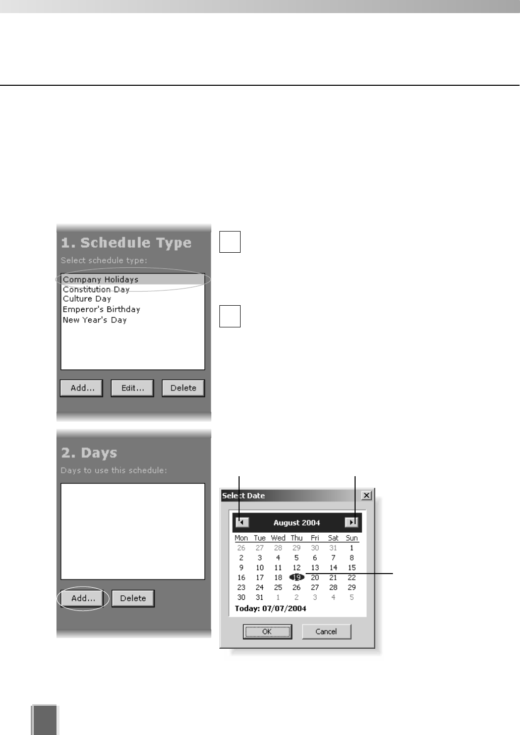
Configure Special Day Recording
84
Add a Day
The Select Date calendar allows you to select a day that can be used for the schedule
type.
To add a day:
Click a Schedule Type and click ‘Add’ below the Days field
Click on a day in the Schedule Type list, for
example, ‘Company Holidays’ (created on the
previous page), and then click the Add button
below the Days field.
This will bring up the Select Date calendar.
Click a day in the calendar to select it and then
click OK to close the calendar (shown below).
Click the Add button again to add another day to
the same schedule type if you wish.
Added days are shown in the Days list (see
example on next page).
Other calendar selection methods are shown on
the next page.
Click to scroll back
through the months.
Click to scroll forward
through the months.
Click a day to
highlight it, then
click OK to bring
up that day in
the Days list.
2
1
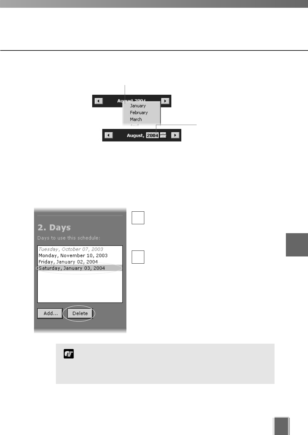
Configure Special Day Recording
85
Delete a Day
To delete a day from a schedule type:
Select a Schedule Type and a day and click the Delete button
ln the Special Day Schedule window, click
a schedule type in the Schedule Type list, for
example, ‘Company Holidays’ and then in the
Days list click one of the days associated with
the schedule type.
Click the Delete button below the Days list to
remove the day from the schedule type.
If you attempt to associate the same day with different special
day schedules, you will be given a warning and asked to delete
the other entry before creating a new one.
Expired days are listed in italics.
Note
To select another year, click
the current year and scroll
up or down, using the
up/down arrows.
Alternatively, click the
current month and a month
selector will appear.
1
26
Configuring Recording Schedules
Saving Special Day Changes
When you have finished Special Day configuration...
The bottom right-hand corner of
the Recording Schedules window
consists of two buttons, Save
Schedule and Discard Changes.
Click Save Schedule to keep all your settings. The settings are then saved to the
Storage Server.
Click Discard Changes to cancel any modifications you have made.
If you wish to return to the Viewing Screen, select View > Viewing Screen from the
menu bar.
86

Chapter 7
Configuring
Viewer Settings
This chapter outlines how to configure settings that are specific to
the Viewer. This is intended for Administrators.
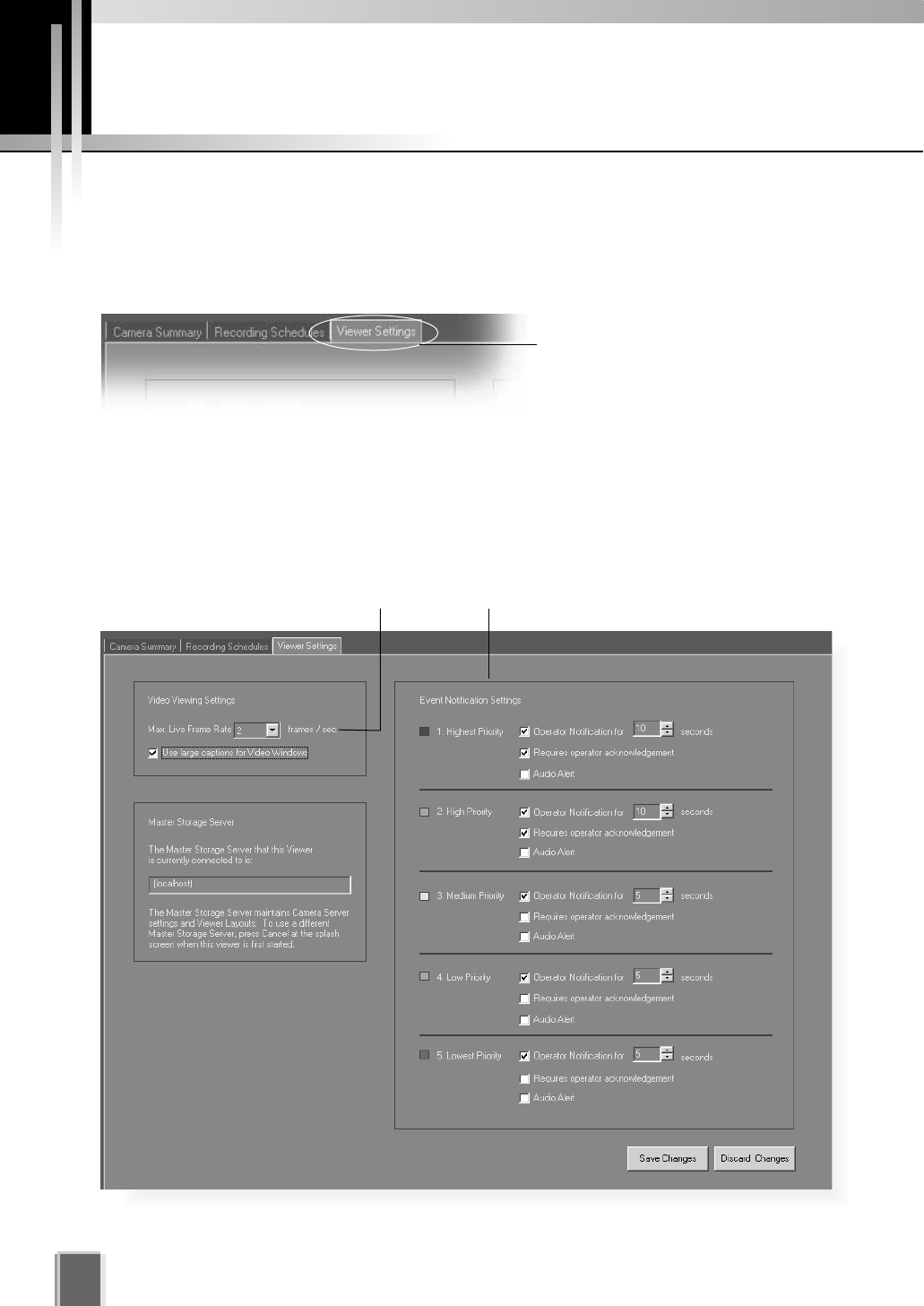
Configure Viewer Settings
88
About the Viewer Settings window
The Viewer Settings window is used for configuring individual Viewer settings such as
notification priorities and the live viewing frame rate. Settings are stored on the Viewer PC,
not on the Master Storage Server.
Click the Viewer Settings tab to
display the window.
This window consists of:
Live Video Viewing Settings - Select from a list of frame rates for live viewing.
Master Storage Server - The current Storage Server is indicated.
Event Notification Settings - Set operator notification and adjust duration in seconds,
set operator acknowledgement (recognition) of an event and set an audio alert.
Event Notification Settings area
Maximum frame rate for live viewing
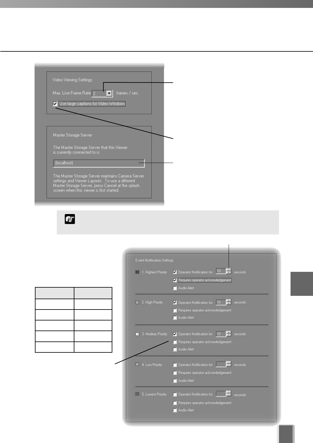
89
7
Configuring Viewer settings
Set up notifications by
priority from 1 (highest) to
5 (lowest). Priorities are
color-coded.
Lower priority items can
have less notification
settings associated with
them.
When an event occurs, it is
indicated in the Live Events
Log in the Viewing Screen.
Select a frame rate from the
drop-down menu. Lower frame rates
ensure less load on the network and
Viewer. This may lead to higher frame
rates for recording and may allow a
larger number of Video Windows to
be viewed.
Enable larger Video Window captions
in the Viewer.
The current Master Storage Server is
indicated here.
Color Priority
Red Highest
Orange High
Yellow Medium
Light Green Low
Dark Green Lowest
If a high maximum frame rate is specified, the load on the
computer CPU will be high and Viewer operations may take longer.
Note
Set duration of alert.
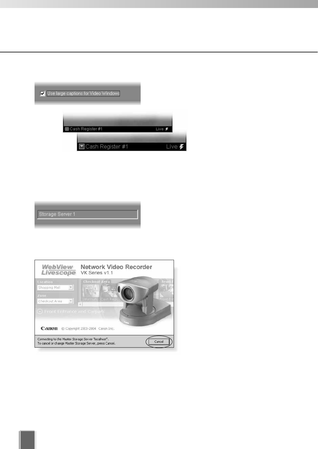
Tick Use large captions for Video Windows to
enable easier-to-read Video Window captions in
the Viewer.
Configure Viewer Settings
90
Viewer Settings window - Identify the Master Storage Server
A Master Storage Server maintains settings for Camera Servers and Layouts created in the
Viewer. Only one Master Storage Server can be assigned to a Viewer at any one time.
The selected Master Storage Server is indicated in
the Viewer Settings window.
If you wish to change the Master Storage Server...
Close the Viewer and then
re-launch it. When the start-up
(splash) screen opens, click the
Cancel button at the bottom of the
screen. A dialog will appear for you to
enter a different Storage Server.
Refer to Chapter 3, page 31 for
more details.
Viewer Settings window - Use large captions for Video Windows
Standard caption in Video Window.
Large caption in Video Window.
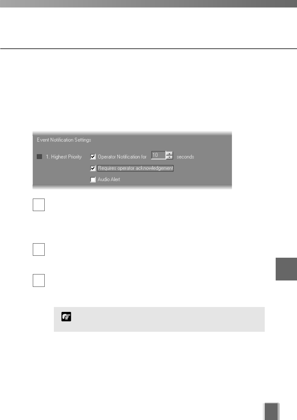
Configure Viewer Settings
91
Viewer Settings window - Edit Event Notifications
When an event occurs, it is indicated in the Live Events Log in the Viewer. In the
Viewer Settings window, Event Notification Settings area, you can set up actions based
on events according to the priority of the event.
To set the event notifications:
Set priority alerts from Highest to Lowest
Tick the Operator Notification for box to enable a notification period when an event
occurs. In the seconds menu, select a period of event notification in seconds or
manually enter a duration from 0 - 99 sec. When an event occurs it will flash in the
Live Events window and a color bar reflecting priority level will be shown at the top of
the Video Window for the period selected. If you select 0, the color bar will light
up without flashing.
Tick the Requires operator acknowledgement box for the event. When an event
occurs it will flash in the Live Events Log and the audio alert will sound (if
specified) until the operator double-clicks on the event (that is, the notification time
will not apply to the event in the event log).
Tick the Audio Alert box to have an audio alert play during the event notification
period. The Windows system sound ‘Exclamation’ is used for audio alerts. This sound
repeats for the duration of the Event Notification setting. If Operator Notification is not
set, the audio alert is played once.
1
2
3
Setting up event priorities and email notification is discussed on
page 25. The Live Events Log is discussed on page 132.
Note
7
Configuring Viewer settings
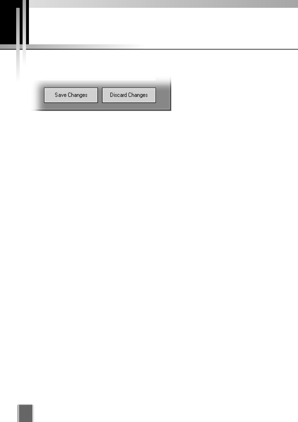
Saving Viewer Settings
92
When you have finished configuring Viewer settings...
The bottom right-hand corner of
the Viewer Settings window
consists of two buttons, Save
Changes and Discard Changes.
Click Save Changes to keep all your settings. The Viewer settings are then saved to
the local disk (the computer the Viewer resides on).
Click Discard Changes to cancel any modifications you have made.
If you wish to return to the Viewer, select View > Viewing Screen from the menu bar.

Chapter 8
Using the Viewer -
Operator Login
This chapter outlines how to start the Viewer and gives a brief overview of the
Viewing Screen.
PART 2: USING THE VIEWER APPLICATION
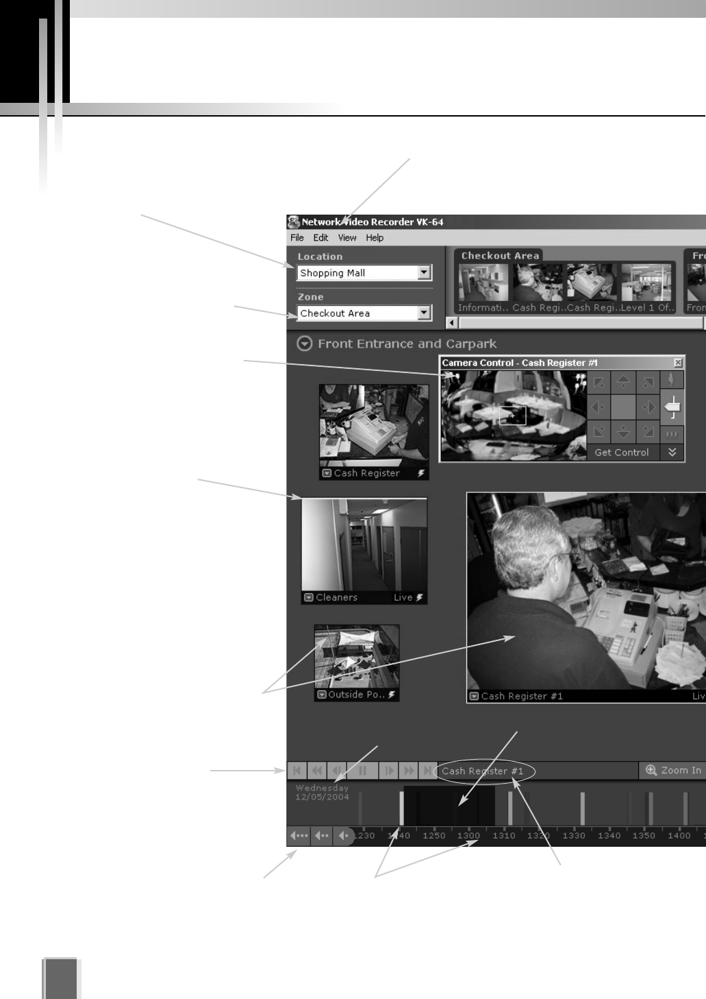
Viewing Screen Example
Location selector
Drop-down menu indicating
locations available in the
system.
Menu bar
Access common
menus from here.
Zone selector
Drop-down menu indicating
zones within a location.
Event indicator
A color bar is displayed at
the top of live Video
Windows when an event
occurs (if enabled).
Camera Control Panel
A range finder enables you
to control a camera and
quickly determine a
camera position.
Viewing Area for
Video Windows
Video Windows can be
re-sized. They can also be
arranged into a uniform grid.
Date indicator
Darker area indicates
available recorded video
Timeline
Colored bars indicate events that
can be selected and viewed.
Click and drag the Time bar to
go back or forwards in time.
Camera Name
Name of camera
currently selected.
Playback controls
Click the VCR-like controls to
play, rewind, fast forward or
jump to previous and next
events.
Incremental Time controls
Scroll back through the current
day or jump back incrementally
by day or week.
94
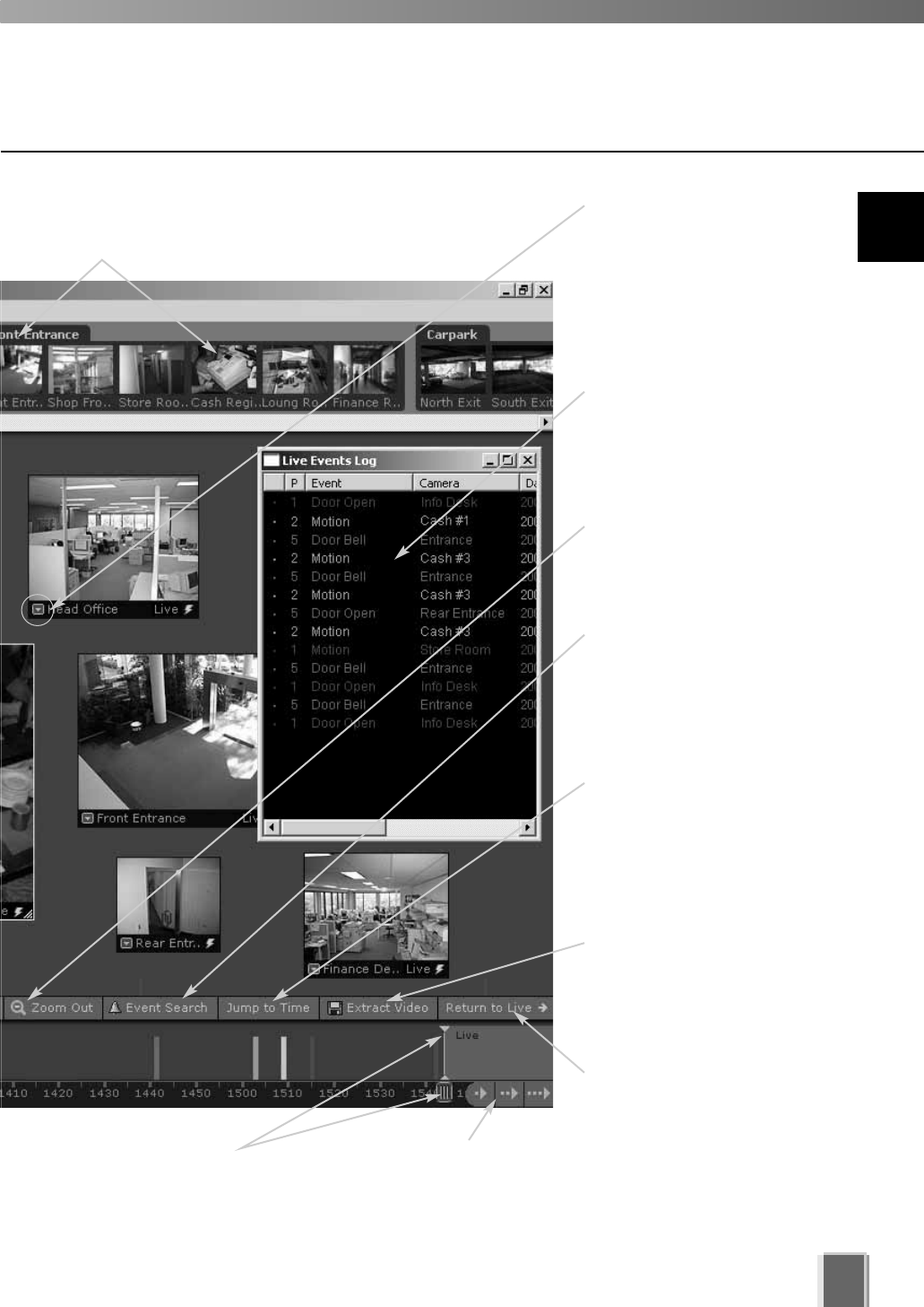
eo
Live Events Log
Indicates events that have
been logged on Storage
Servers after the Viewer
was launched.
Video Window menu
Select preset camera
angles as well as custom
pan, tilt and zoom. Initiate a
manual recording, capture
a still frame and select a
Video Window size.
Zoom controls
Click to zoom in or out of
the Timeline.
Jump to Time button
Click to enter a specific
date and time to jump to,
to start playing recorded
video. The Timeline moves
to the time selected.
Extract Video
Click to extract a segment
of video to save as another
file.
Return to Live t
Click to return the Timeline
playhead to the current time.
If you click this button while
playing recorded video, the
selected Video Window will
return to live video.
Incremental Time controls
Scroll forwards through the
current day or jump forward
incrementally by day or week.
Timeline playhead
Click and drag to positions
on the Timeline to show
video from that time.
Camera Selection Area
Thumbnail representations of cameras can be
dragged onto the Viewing Area for viewing.
95
Event search
Click to bring up a dialog
and enter search details
based on time range,
Location/Zone and priority.
8
Using the Viewer - Operator Login
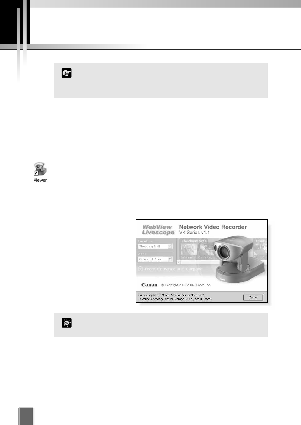
Launching Procedure
Before you launch the Viewer, make sure your monitor resolution is set to a minimum of
1024 x 768 pixels.
Step 1: Launch from the Viewer icon on your desktop
Double-click the Viewer desktop icon.
Alternatively, from the Windows Start menu select:
Programs > WebView Livescope > Network Video Recorder VK Series v1.1 > Viewer.
The application window appears.
Wait until it clears itself before
continuing.
Starting the Viewing Screen
96
Before you can use the Viewing Screen, make sure you have a
password. Access is setup by your System Administrator. If you
have Administrator privileges, you can also configure Network
Video Recorder settings.
Note
If a connection error occurs, you may not have a Master Storage
Server connected. See your System Administrator.
Tip
Yo
p
v
(t
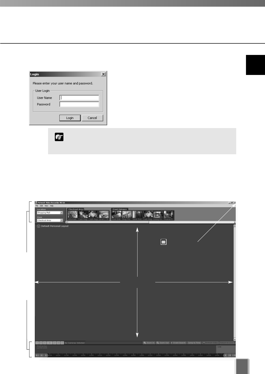
Step 2: Enter User Name and Password
After launching, the Login dialog will appear. Enter
your User Name and Password (tP. 30), and then
click the Login button to continue.
The Viewing Screen will appear.
97
8
Using the Viewer - Operator Login
Viewing Area
Click to maximize
the Viewing Screen.
If no Layouts have been configured, you will notice that the Viewing Area is blank as shown
below. Previously-configured cameras on the network will appear as thumbnail images in
the Camera Selection Area on the top of the screen. These can be dragged onto the
Viewing Area for monitoring. If your Administrator has already created a Layout for you,
then the Viewing Area will display the first Personal Layout (or first Shared Layout if there
are no Personal Layouts) as shown in the example on the previous pages.
Your VK-64 User Name and Password will have been set up in the
Storage Server Configuration utility and may be different from your
Windows User Name and Password.
Note
You can
hide
these
panels
via the
View
menu.
(tP. 98)
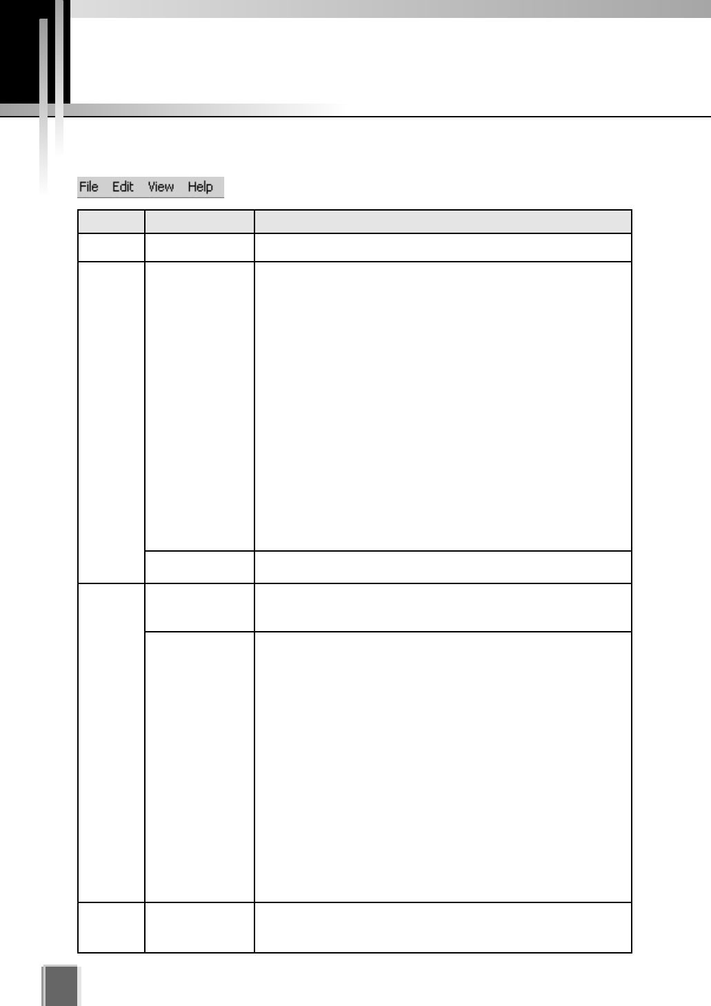
Viewing Screen Menu bar
98
Menu Bar Functions
The following table lists the Viewing Screen menus.
Menu Menu sub-item Function
File Exit Closes the application.
In the Viewing Screen, this action removes the selected Video Window
and places it on the clipboard to be pasted into the same or another
Layout.
In the Viewing Screen, this action copies the selected Video Window
and places it on the clipboard to be pasted into the same or another
Layout.
In the Viewing Screen, this action pastes the cut or copied Video
Window into the current Layout.
In the Viewing Screen, this deletes selected Video Windows from the
current layout.
In the Storage and Camera Server Summary screen, this deletes
selected Storage Servers, Camera Servers, Locations or Zones.
In the Recording Schedule screen, this deletes selected Normal or
Special Day schedules.
In the Viewing Screen, this action selects all Video Windows in the
current Layout.
Launches the Event Search dialog.
Selects the Configuration and Preferences Screen if the Viewing
Screen is open.
Selects the Viewing Screen if the Configuration and Preferences
Screen is open.
Hides the Menu Bar and Title Bar to allow more display room for Video
Windows. Clicking the Esc key restores the Viewer to its previous state
(i.e., before selecting the Full Screen mode).
Hides Video Window captions to allow full Video Window display.
Hides the Camera Selection Area.
Hides the Timeline Area.
In the Viewing Screen, this action opens the Live Events Log at the
position and size that it was last open. A tick beside the menu item
indicates that the screen is open. Selecting the menu item again will
close the window and the menu item will be unticked.
Brings up the Camera Control Panel where you can set the viewing
position and zoom.
This action opens the ‘About’ box featuring the startup ‘splash’ screen
with version number.
Edit
View
Help
Cut
Copy
Paste
Delete
Select All
Search Events
Configuration
Viewing Screen
Fullscreen
Captions
Camera Selector
Timeline
Live Events
Camera Control
About

Chapter 9
Working with
Video Windows
This chapter shows you how to create Video Windows for viewing
in the Viewing Area and how to adjust camera angles.
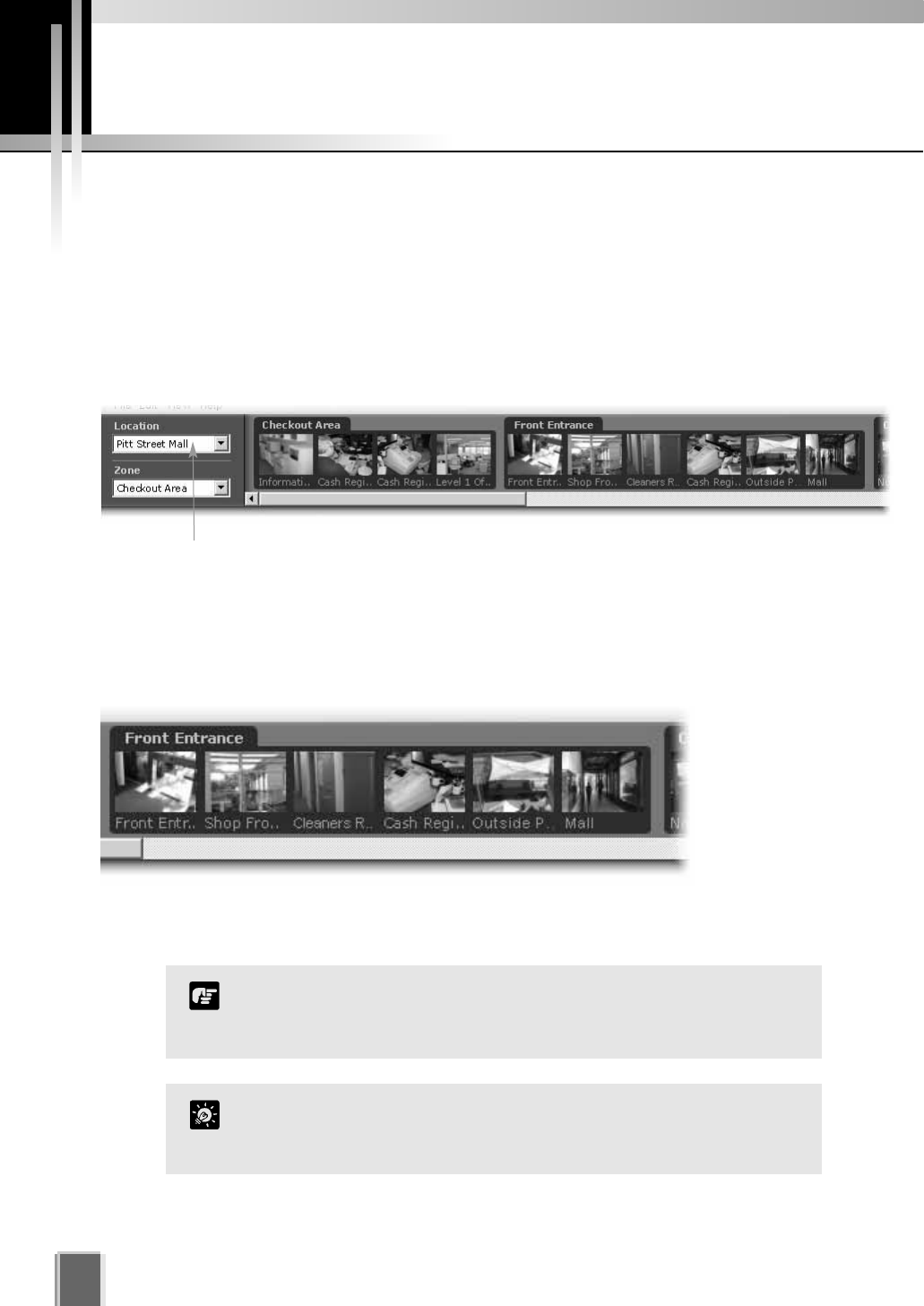
About the Camera Selection Area
The Camera Selection Area is used to display all the cameras currently available for
monitoring from the network. You can select currently-available cameras via the Location
and Zone drop-down menus and then place them into the Viewing Area as Video Windows.
The Location drop-down menu lists the physical locations of cameras on the
system.
The Zone drop-down menu lists the groups of areas within each location.
Selecting Cameras for Viewing
100
Locations, zones and thumbnails are configured and managed by
users with Administrator privileges. You must have Administrator
privileges in order to modify settings.
Note
About Camera Thumbnails
When a Location is selected, zones within that location appear as thumbnail ‘folders’ to the
right of the Location and Zone menus. A scrollbar at the base of the Camera Selection Area
can be used to scroll the display of thumbnails.
Each Zone is grouped into camera thumbnail images and these can be dragged onto the
Viewing Area to create Video Windows.
When you select a location, its associated zones will be listed below.
You can hide the Camera Selection Area to allow more display
space for Video Windows. From the View menu, select Camera
Selector to hide/show the Camera Selection Area.
Tip
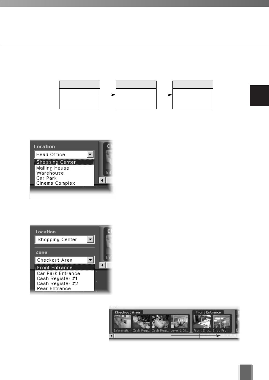
9
Working with Video Windows
101
Selecting Locations and their Zones
Selection is performed in the following order:
Step 1: Select a Location from the drop-down menu
Click the Location drop-down menu or on the down
arrow.
A list of pre-configured locations appears.
Click a location in the list. Zones for that list will
appear in the thumbnail section to the right.
Step 2: Select a Zone from the menu or thumbnail folder region
Click the Zone drop-down menu or on the down
arrow.
A list of pre-configured zones appears.
Click a zone in the list.
Once a Zone is selected from the drop-down menu,
the Camera Selection Area for the selected Zone
moves to the left.
Alternatively, click the scrollbar
located under the Camera
Selection Area. Drag it to the
right until the desired Zone is
displayed.
Select a
Location
Click and drag
thumbnails to
view live video
Select a Zone
in that Location
1 32
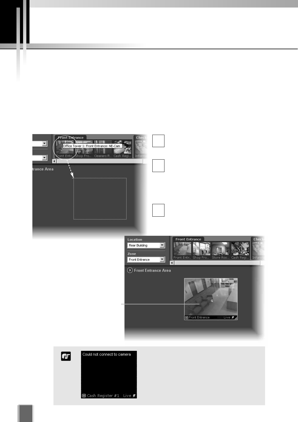
Creating, scaling and moving Video Windows
Once you have chosen a location and chosen a zone, you are ready to view one or more
cameras in that zone. Camera thumbnail images are used to create Video Windows in the
Viewing Area. The Viewing Area can support multiple Video Windows for live monitoring
and viewing recorded video simultaneously.
Click and drag a camera thumbnail onto the Viewing Area
Move your mouse pointer over a
thumbnail. A tooltip will indicate the
Location, Zone and camera name.
Click the thumbnail image and, while
holding down the mouse button, drag
its boundary anywhere onto the
Viewing Area (the thumbnail becomes
an outline which is re-sized when you
drag it over the Viewing Area).
Release the mouse button. The
re-sized outline becomes a live Video
Window.
102
1
2
3
Basic Video Window Functions
An error message will appear in the Video
Window if there is a connection problem.
Refer to the Troubleshooting Appendix at
the back of the manual, or see your System
Administrator for configuring cameras and
Camera Servers.
Note
When placed, the Video Window
is re-sized and re-positioned
according to the selected layout
grid (discussed on page 119).
A selected Video Window is
highlighted.
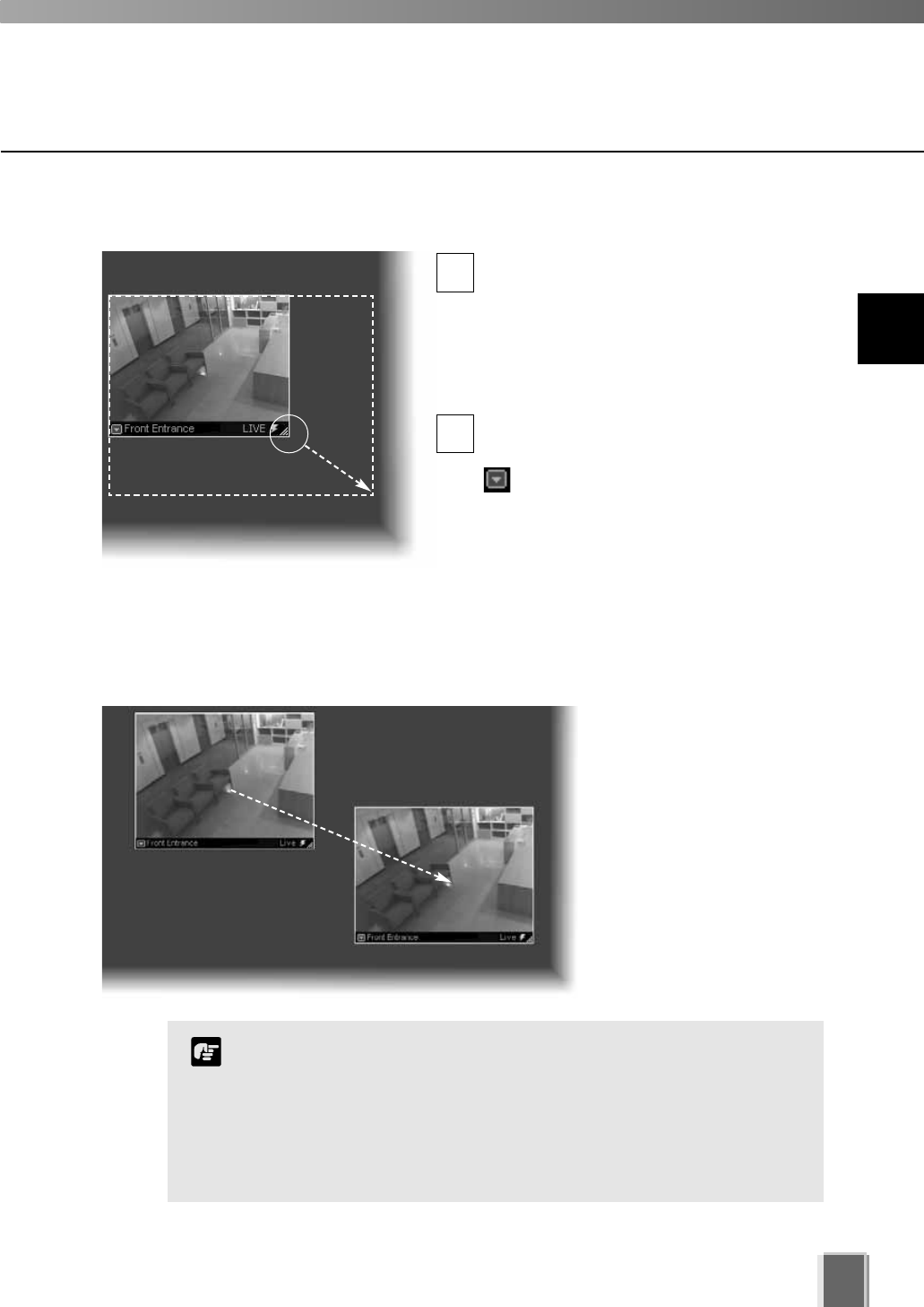
Re-size a Video Window
Click a video window to highlight it. An
arrow icon will appear in the lower right
corner. Click the arrow icon and drag
outwards (the mouse pointer becomes a
double-arrow). You can also click on the
other corners and drag to re-size the
window.
Release the mouse button when you have
reached the desired size.
Alternatively, click the Video Window
menu button and select Video
Display Size. Choose from one of the size
options in the sub-menu, Small, Medium,
Large or Raw.
A right-click action on the Video Window
will also bring up the same menu.
Move a Video Window
Click anywhere on a Video
Window and drag it to any
position in the Viewing Area.
103
1
2
For best performance on the Viewer, such as to view as many
Video Windows as possible, re-size the Video Windows so they
are a standard resolution; for example, selecting ‘Medium’ from
the Video Window menu.
When Video Windows that are other than a standard resolution
are displayed, the load on the computer CPU will be high and
Viewer operations may take longer.
Note
9
Working with Video Windows
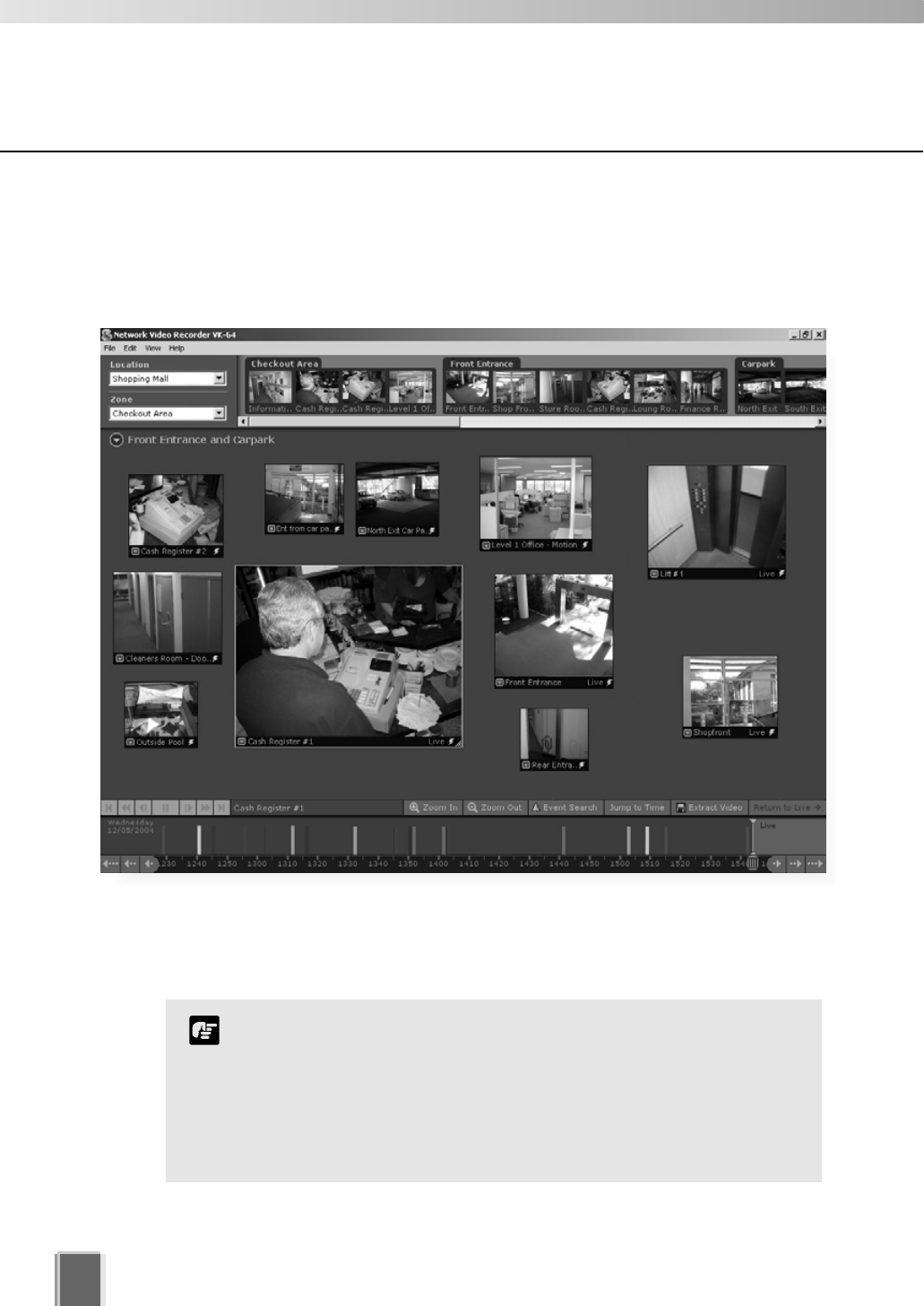
104
Basic Video Window Functions
Step 3: Add more Video Windows
Click and drag other camera thumbnails onto the Viewing Area to create Video Windows
for monitoring. Your Viewing Screen could look like this.
Arranging Video Windows
There are various ways you can manage the layout of Video Windows in the Viewing Area
and this is discussed in the next chapter.
In the Viewer, the number of Video Windows you can display
simultaneously will depend on your video card, the resolution
and quality settings of the camera and the Live Video Viewing
Settings (frame rate) set in the Viewer Settings window of the
Configuration and Preferences screen.
If the load on the computer CPU is high, Viewer operations may
take longer.
Note
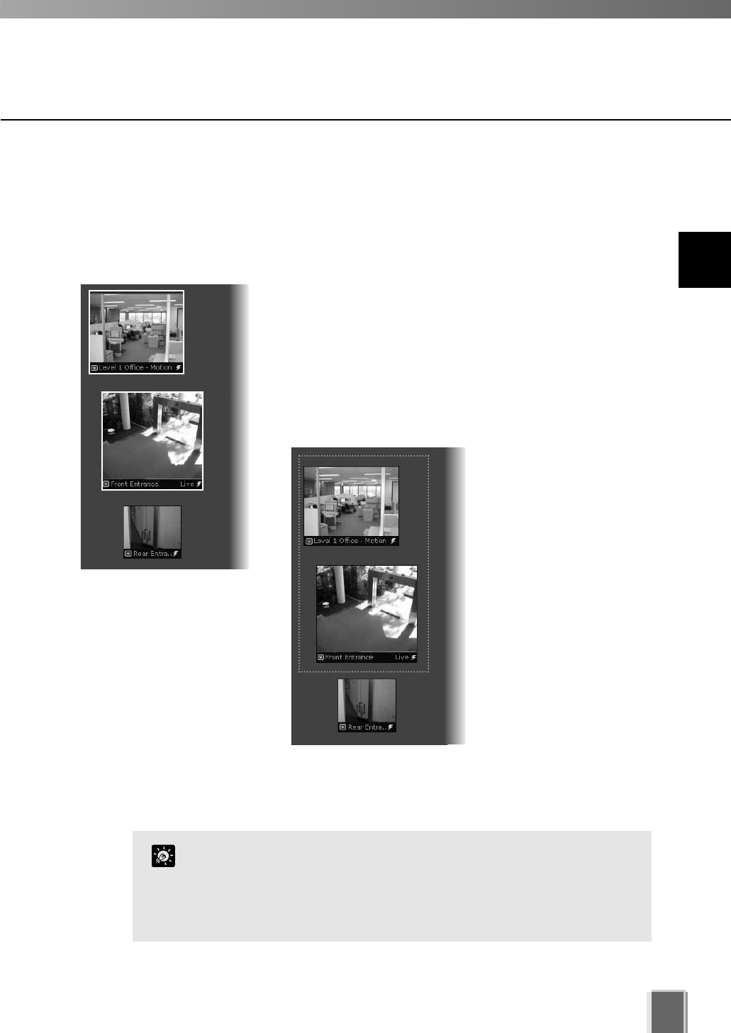
105
Selecting Multiple Video Windows
You can select multiple video windows easily.
To select more than one Video Window:
There are three ways to select multiple windows:
On your keyboard, hold down the Ctrl key and click each
Video Window to select them, or
Click outside the Video Windows and drag a
selection box around the Video Windows you want
selected, as shown below. Only windows contained
within the area of selection are selected, i.e., dragging
around part of an image will not select it.
Basic Video Window Functions
Video Windows from different zones and locations can be
displayed in the same Layout.
You can copy and paste a multiple selection of Video Windows
at one time which can be pasted into and saved as a new
Layout.
Tip
If you wish to select all Video Windows, click Select All
from the Edit menu (or on your keyboard press
Ctrl + A).
9
Working with Video Windows
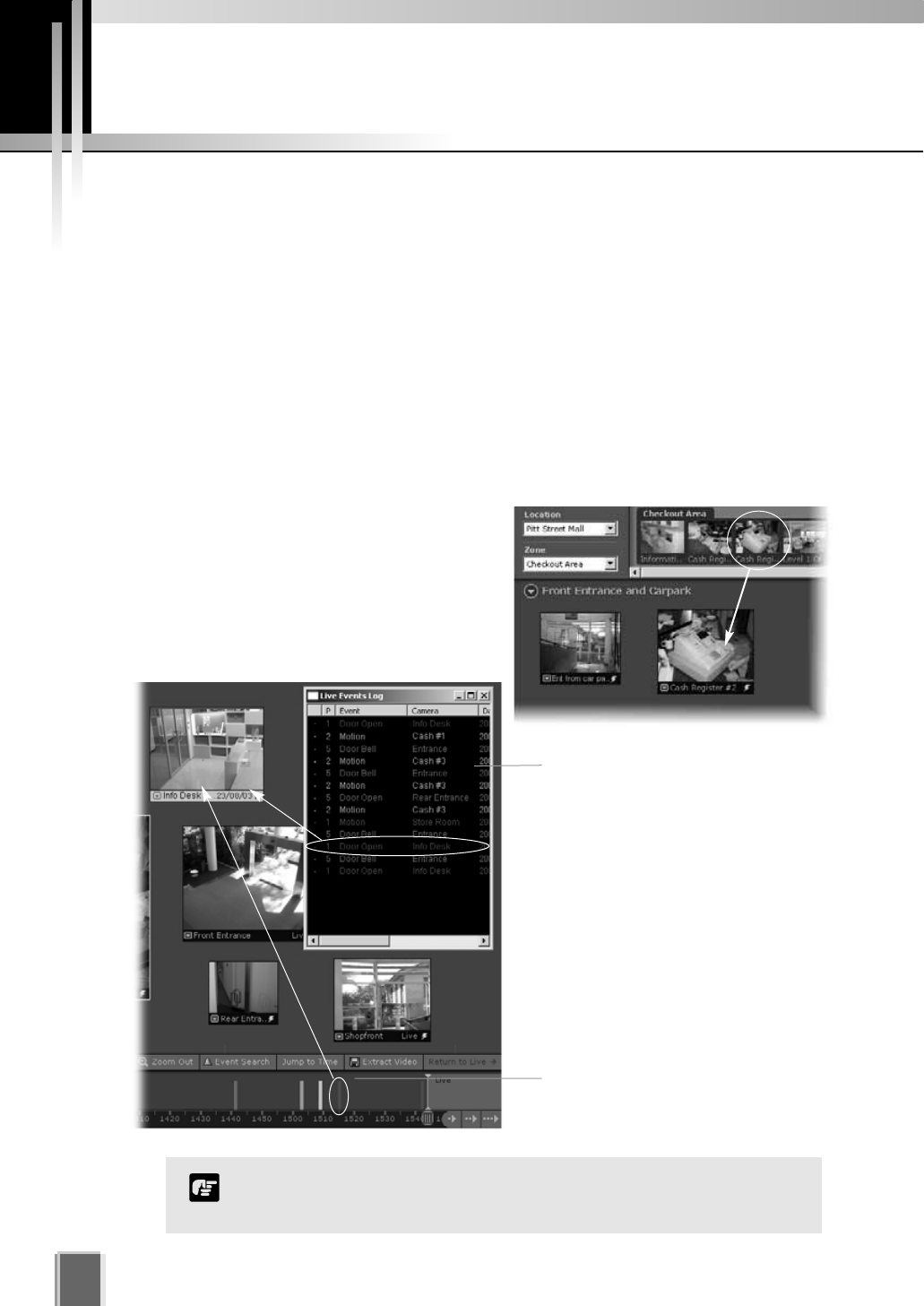
106
About Video Window states
Video Windows can be displayed in the Viewing
Area according to their conditions:
Live - when viewing live video from a
Camera Server.
Pre-recorded - when viewing recorded
video from a Storage Server.
Video Window States
Video Window Properties include:
Title bar - indicates name of camera, live or recorded viewing.
Video display - displays live or recorded information.
Pre-recorded video indicator - displays a time/date stamp in the title bar for
recorded footage.
Event indicator - displays a colored bar across the top of the Video Window.
Pan, tilt and zoom controls - when the Video Window is double-clicked or the Video
Window menu item, Get camera control is selected, controls appear to enable pan,
tilt and zoom.
Live Events Log
When configured, it displays when
you launch the Viewer.
Double-click an event to view it in
the corresponding Video Window.
Pre-recorded
Click to view recorded footage in
the corresponding Video Window.
The full camera name/event may not display if you reduce the size
of the window.
Note
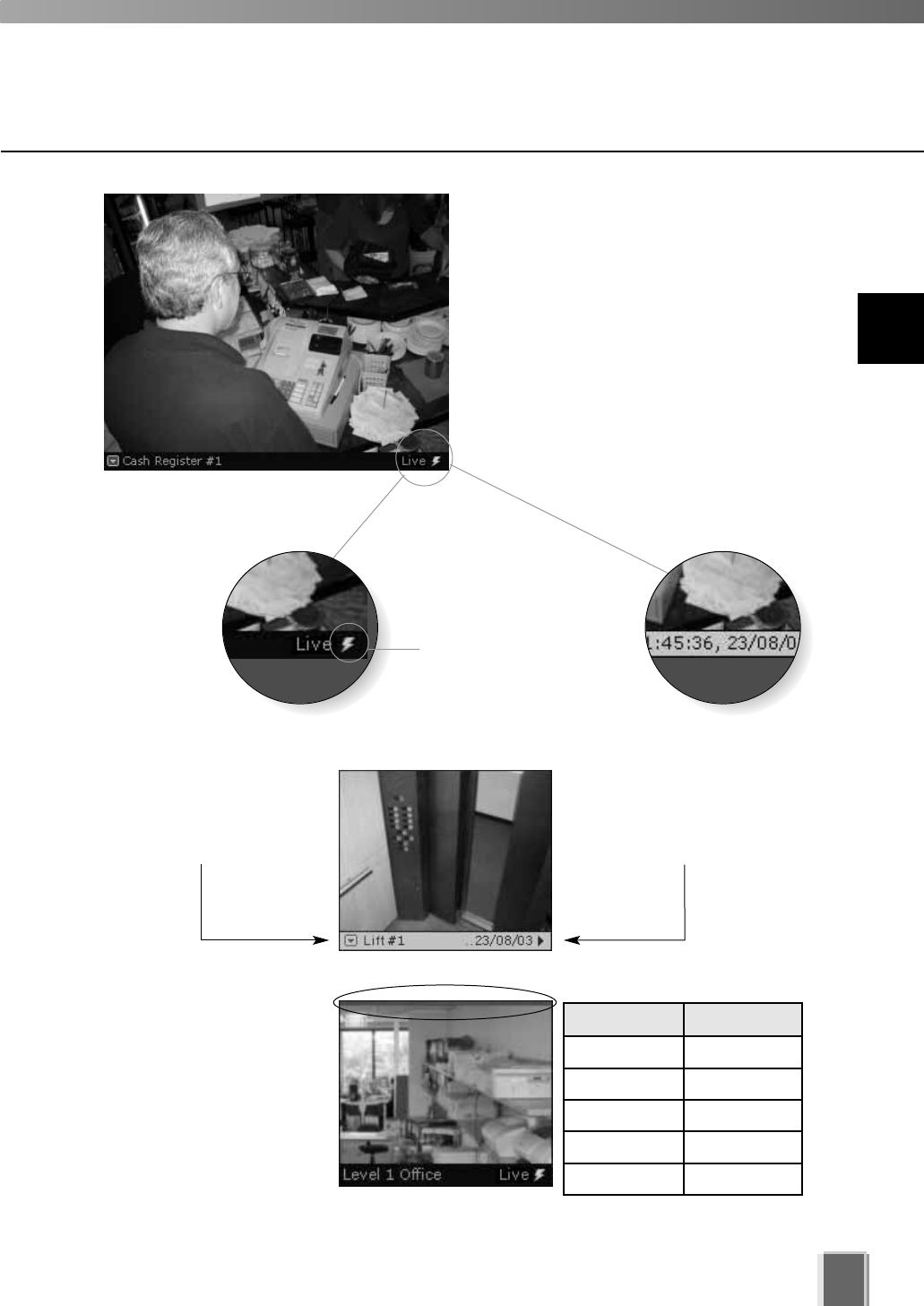
107
If the option for Operator
Notification has been set
(tP. 89), a color bar will
flash on top of a live Video
Window when an event
occurs. The color indicates
the event priority. The bar
will flash for a pre-defined
time and then remain steady
for one minute until disappearing. An audio alert may
also sound if pre-defined.
Live video,
Normal status
Recorded video,
Playback
Each Video Window displays video from an
individual camera. Video Windows can be
re-sized, repositioned or closed.
The lightning symbol
in the lower right-hand
corner indicates live video.
Title bar
The title bar consists of menu, camera name
and live or recorded status.
Video display conditions
Event Indicator
Color Priority
Red Highest
Orange High
Yellow Medium
Light Green Low
Dark Green Lowest
For recorded video, the
time/date indicator may not
fully display if the Video
Window size has been
reduced.
When recorded video is
shown, the title bar on a
Video Window will change
from black to gray.
Pre-recorded Video Indicator
9
Working with Video Windows
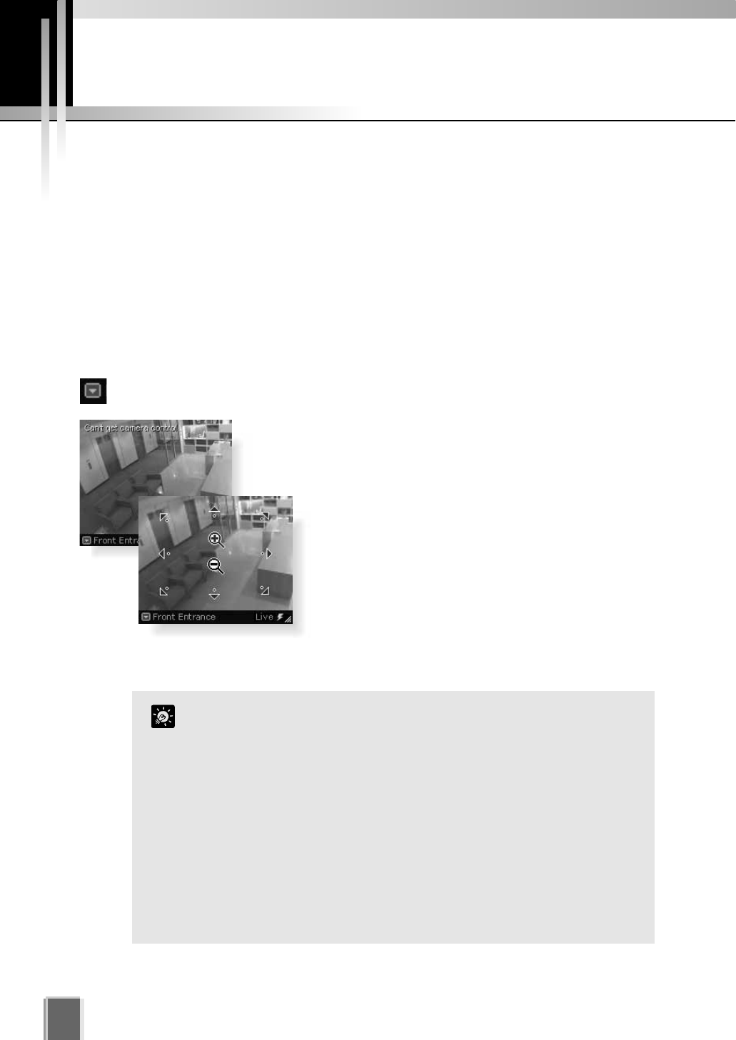
Adjust Pan, Tilt and Zoom
108
Directly from within the Video Window
First enable the controls by double-clicking on a live Video Window.
Alternatively, click the down-arrow at the base of the Video Window (or right-click on
the window). A drop-down menu will appear. Select Get Camera Control.
If the camera is being used by the Admin Viewer or another VB
Administration Tools associated with the camera server, a ‘Can’t
get camera control’ message will appear. You may have to wait a
few moments and attempt to get control later.
Move the mouse cursor around the Video Window.
Arrows will appear in the cursor position when you have
gained control of the camera. Click and drag the cursor
in the direction of the arrow for pan and tilt.
When you move the mouse cursor to the center of the
image, a zoom in or zoom out control will appear. Hold
down the mouse on ‘+’ to zoom in. Hold down the
mouse on ‘-’ to zoom out.
When you have finished, select Release Camera Control from the Video Window menu.
If Pan, Tilt and Zoom are active in a Video Window, you can only
drag the window by clicking and holding the title bar.
When you have control, the camera can be controlled either by
clicking or moving the mouse while holding the left button
down. The latter method provides finer control.
If a control warning, “Control will be lost in 10 seconds.”
appears, it means you have stopped making changes for 30
seconds and a 10 second countdown commences. To continue
control, click in the Video Window, i.e. use the controls.
You can still manipulate a camera that is currently recording. If
a camera position is defined for recording, the camera will
return to that position when you release control.
Tip
Viewing Live Video - Adjusting Pan, Tilt and Zoom
This is done in one of three ways: (VB-C50FSi and VB-C50Fi have Zoom only).
Directly from within the Video Window,
Using the Camera Control Panel, or
Selecting a Preset Camera Angle.
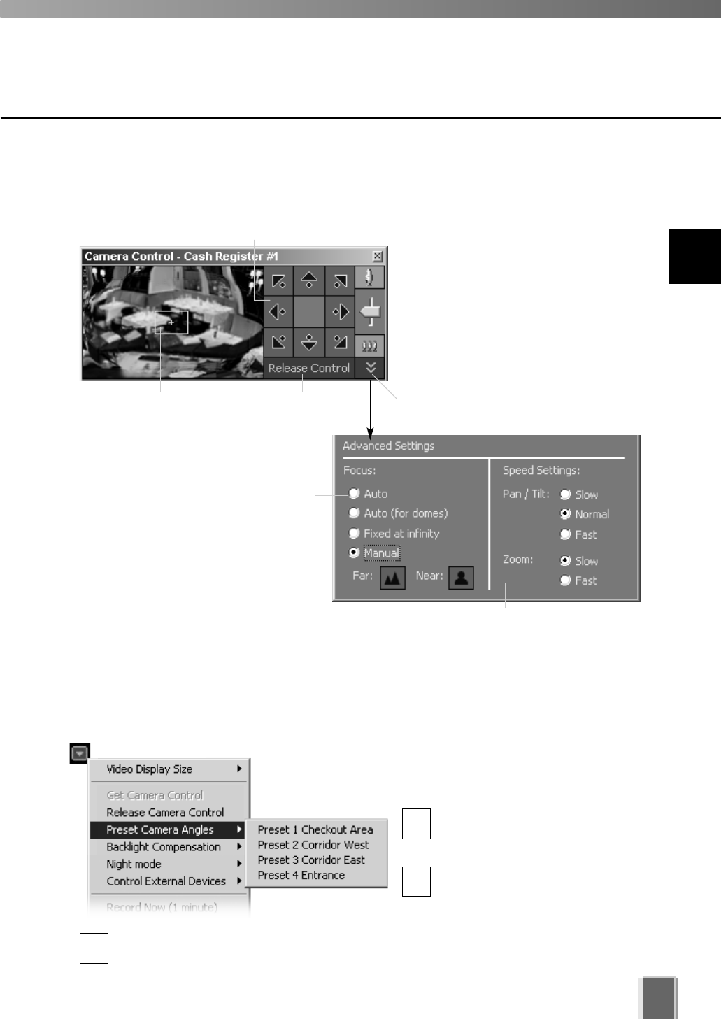
Selecting a Preset Camera Angle
If preset camera angles have been set up by your
Administrator, they will be available from a sub-menu.
Double-click a Video Window or
select Get Camera Control from
the Video Window menu.
From the Video Window menu,
click Preset Camera Angles.
Select a preset position from the sub-menu. If there are no preset positions listed, see
your Camera Server Administrator.
109
Using the Camera Control Panel
1
2
3
When you have finished, select Release Camera Control from the active Video
Window menu.
When the Video
Window is selected,
click Get Control.
Click Release Control
when finished.
Pan/Tilt controls. Click to
nudge or click and hold for
continuous movement.
Click and drag
range finder or
click away from
it to reposition.
Click and drag
Zoom slider.
To display, select View > Camera
Control from the VK-64 menu bar.
If a Video Window is not selected, the
preview window will be blank. Click on
a Video Window to display a ‘range
finder’ in the Camera Control Panel. A
full area panorama is given which acts
as a ‘map’ for quickly locating
suitable viewing angles. Actions are
reflected in the selected Video
Window.
Click the arrow to open settings for
finer control...
In the Focus: field, select Auto if
constant camera manipulation is
required. Otherwise select another
option to suit particular views.
In the Speed Settings: field, you can set
the movement rate for Pan, Tilt and Zoom.
9
Working with Video Windows
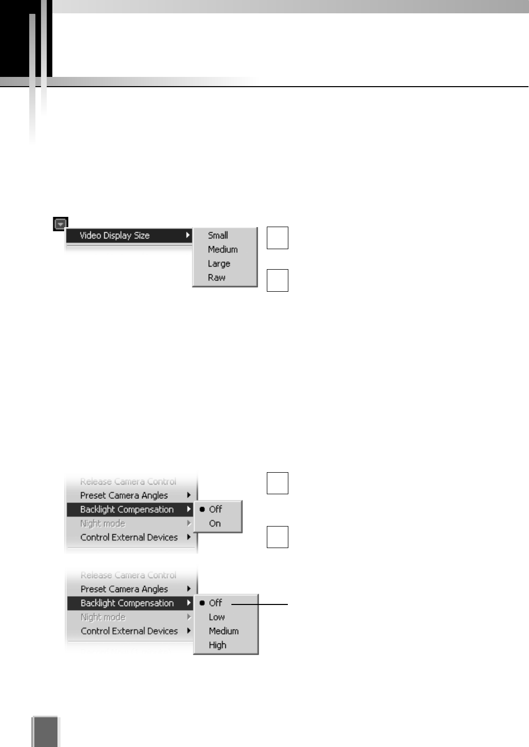
Other Video Window Functions
110
Change the size of a Video Window
Apart from manually clicking on the corner and dragging out the Video Window to a new
size, you can also select a set size from the Video Window menu.
To change the display size of a Video Window via the menu:
Open the Video Window menu and select ‘Video Display Size’...
Click the Video Window menu icon, or
right-click in the Video Window to bring
up a context menu.
Select Video Display Size from the
menu, and then select Small,
Medium, Large or Raw from the
sub-menu. A Raw selection displays
the video window in its original size.
1
2
Enable Backlight Compensation
Backlight compensation is a camera feature used to compensate for camera views with
strong backlighting, i.e., viewing a dark image against a strong backlight. It can be enabled
from the Video Window menu. It is not to be confused with Shade Correction (tP. 112).
To enable backlight compensation:
While Camera Control is active, select ‘Backlight Compensation’
If the menu is not open, click the Video
Window menu icon (or right-click in the
Video Window to bring up a context
menu).
Select Backlight Compensation from
the menu and then select On or Off
from the sub-menu.
If you are using a VB-C50i, VB-C50iR,
VB-C50FSi or VB-C50Fi, the Backlight
Compensation options are High,
Medium, Low or Off.
1
2
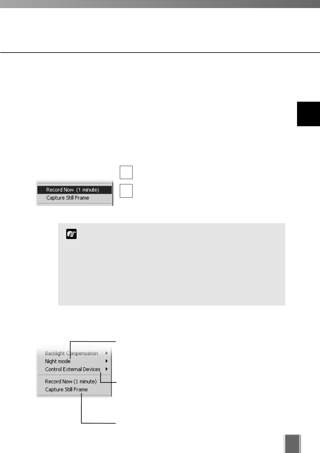
111
User-initiated Recording
A manual recording with a duration of one minute can be initiated at the maximum frame
rate. The manual recording is displayed on the Timeline and Live Events Log as ‘Manual
Rec. (username)’. This is handy for capturing random events not associated with sensor
recording or outside preset recording times. You must ensure a Storage Server is
associated with the Video Window, otherwise recording will not be possible. This can be
configured by an Administrator in the Configuration and Preferences screen.
To initiate manual recording:
Open the Video Window menu and select ‘Record Now (1 minute)’...
Click the Video Window menu icon, or right-click in
the Video Window to bring up a context menu.
Select Record Now (1 minute) from the menu. You
will notice an indicator showing manual recording.
When recording is in progress, click ‘Record Now’
again to extend recording (the counter is reset).
1
2
The Record Now function records at the maximum frame rate.
Extended recording time will use additional disk space on the
Storage Server. Excessive use of this function should not be
performed without first checking with an administrator.
The Record Now function is only enabled if a Storage Server is
configured for the camera.
Recording will be for approximately one minute. The actual
duration of recorded video may vary depending on settings and
network delays.
Note
9
Working with Video Windows
Click Night mode and select Disabled, Enabled, IR light
off or Enabled, IR light on from the sub-menu. Selecting
Enabled, IR light on will remove the IR cut filter and turn the
built-in IR light on. The IR light cannot be used with
VB-C50FSi or VB-C50Fi.
Click Control External Devices to control any external
devices that may be connected to your Camera Server. This
is only enabled when you have camera control. For more
information on external devices, see your Camera Server
administrator.
Click Capture Still Frame to keep the current image on a
Video Window for archiving or emailing to other users.
Other Menu Options
Other functions available from the Video Window menu include:
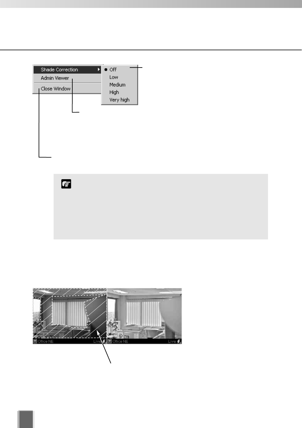
Other Video Window Functions
112
Click Shade Correction to correct shaded
areas in the Video Window. This affects the
individual Video Window on display, i.e.,
any duplicate (unselected) windows are not
affected. Shade Correction is discussed below.
Click Admin Viewer to activate the WebView Livescope Admin Viewer
if it is installed and you are running VK-64 in Administrator mode. Using
the Admin Viewer, you can send/receive audio to/from the VB-C50i,
VB-C50iR or VB-C50FSi if it is configured to enable audio functions.
Refer to your VB-C50i/VB-C50iR, VB-C50FSi User’s Manual for more
information on the settings.
Click Close Window to close the Video Window that is currently selected. You can
also close a selected Video Window by pressing the Delete key.
It is recommended you install the Admin Viewer in advance.
Shade Correction cannot be applied to multiple Video Windows.
If you enable it on a Video Window, it will be removed from any
other Video Window.
Shade correction is performed by using image processing
within the Viewer and not on the Camera Server. It can be used
on live or recorded video (see below).
Note
About Shade Correction
Shade Correction compensates for images consisting of lighter regions and darker regions.
A ‘balance’ is achieved by increasing the brightness of shaded regions without adversely
affecting the existing lighter regions (unlike Backlight Compensation).
Unlike Backlight Compensation
(a feature installed on cameras)
Shade Correction does not
affect the camera itself.
Correction only applies to the
displayed Video Window in the
Viewer.
Shade Correction Off Shade Correction High
Darker regions are most affected by Shade Correction.

Chapter 10
Arranging and Saving
Video Window Layouts
This chapter details how to create and save Video Window Layouts
and Layout Sequences.
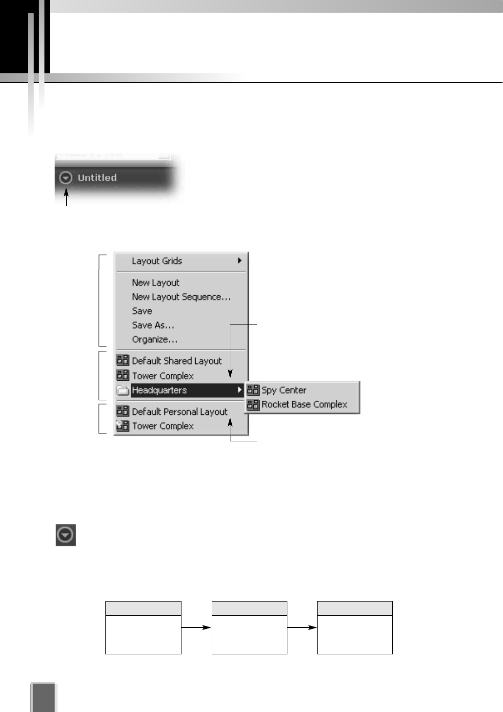
Managing Video Layouts
114
About the Layout menu
The Layout menu allows you to save particular Video Window layouts for easy monitoring
and access of cameras.
The name of the currently-displayed layout can be found in
the top-left corner of the Viewing Area, next to the Layout
button. You can create a new layout, save a layout or open
and rename a previously-saved layout.
Click the Layout button to open the Layout menu. You can also right-click anywhere in the
Viewing Area to display the Layout menu.
Personal Layouts: lists layouts created
by the current user. They are separated
below the Shared Layouts list.
Below the Layout menu options, existing
Layouts are displayed and divided into two
sections, Shared Layouts and Personal
Layouts, as shown in this example.
Shared Layouts: lists layouts created by
Administrators that cannot be modified by
Operators; however Operators can save
layouts under a new name in the Personal
Layouts list below.
Shared
Layouts
Personal
Layouts
Layout
menu
options
To create a new layout (if a previously-saved layout is displayed):
Click the Layout button to open the menu, and then select New Layout. You may be
prompted to save the current layout if it is not saved. The Viewing Area will become
blank and the default layout name ‘Untitled’ will be displayed.
The process of creating folders and saving a layout could be done in the following
order:
Organize and
create Layout
folders
Save Layout to
a folder
Select a grid
style for a new
Layout
1 32
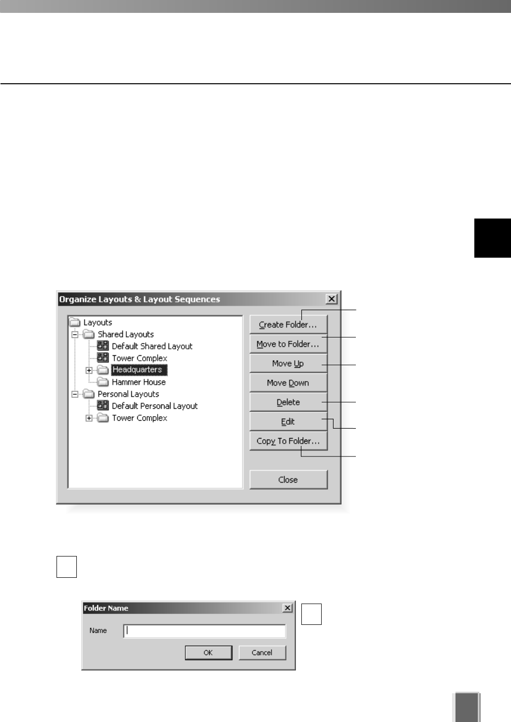
Organizing Layouts and Layout Sequences
The Organize Layouts & Layout Sequences dialog allows you to create folders and
sub-folders in which to save layouts and layout sequences (tP. 118). To display the dialog:
Open the Layout menu and select ‘Organize...’
The Organize Layouts & Layout Sequences dialog opens (Administrator version shown).
The Shared Layouts folder will not display if you have logged in as an Operator.
In this example, several folders have been created with previously-saved layouts. When
you select a Shared or Personal layout folder, the Create Folder button is available. It
allows you to create a sub-folder for that item. When you select a sub-entry, further buttons
are activated...
115
10
Arranging and Saving Video Window Layouts
Create a new folder.
Move an item to
another folder.
Move an item up or
down within a folder.
Delete an item or
folder containing items.
Edit an item name.
Copy an item to
another folder.
Create a new folder...
In the Organize Layouts & Layout Sequences dialog, click on a shared or
personal folder and then click the Create Folder... button.
The Folder Name dialog appears.
Enter a name up to 20
characters and click OK.
The new folder will appear in
the Organize Layouts &
Layout Sequences dialog.
1
2
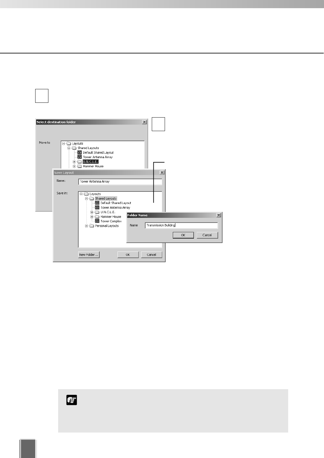
Managing Video Layouts
116
Move or Copy a layout or layout Sequence to another folder...
In the Organize Layouts & Layout Sequences dialog, click an item to highlight it,
then click the Move to Folder... button.
The Select destination folder dialog opens showing a list of created folders.
Click a folder in the list to highlight it, and
then click the OK button to close the dialog.
The item will be moved into that folder.
1
2
Move an entry up or down...
Click an item or folder to highlight it, then click the Move Up or Move Down button. The
item will move up or down within a folder.
Edit or delete a layout or folder...
Click an item or folder to highlight it, then click the Edit button. The respective Layout
Name or Folder Name dialog will appear for you to overwrite a new name.
Click an item or folder to highlight it, then click the Delete button. A confirmation dialog will
appear. Click Yes to continue or No to retain the item or folder. If you have Operator
status, you will not be able to delete a shared layout or layout sequence.
You cannot change the parent folder names, Shared Layouts or
Personal Layouts.
Only Administrators can see and organize shared folders and
shared layouts.
Note
If you selected the Copy to Folder...
button, a similar dialog will appear, only
this time the item is duplicated. A New
Folder button and Name field is also
available for you to create a new name and
location for the copied layout or layout
sequence.
Administrator dialogs shown.
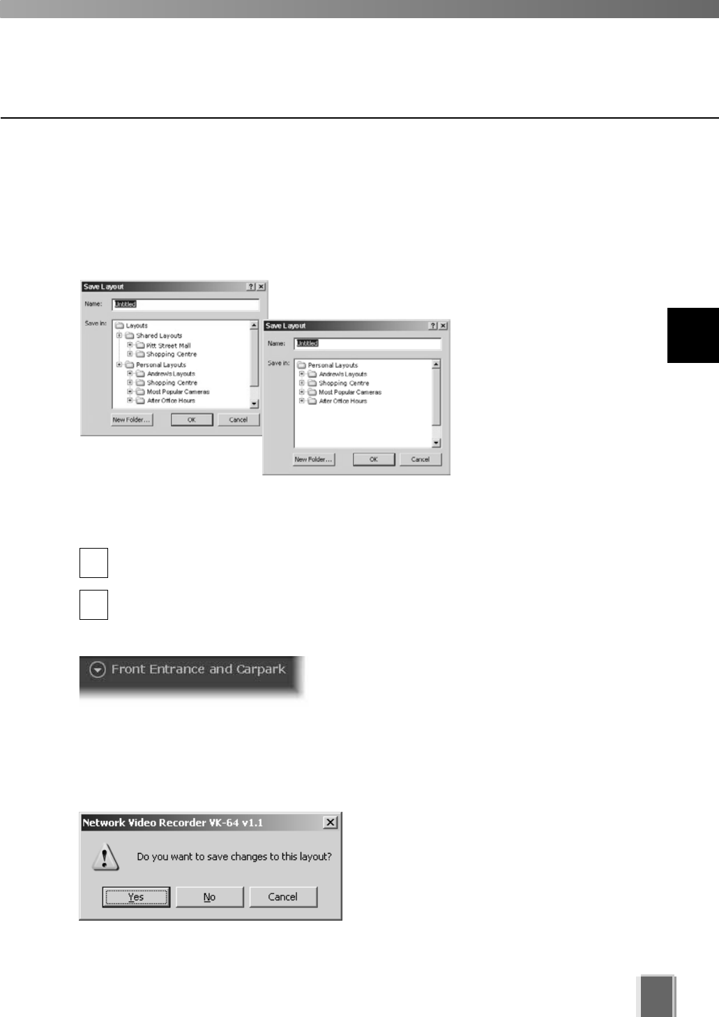
Managing Video Layouts
117
Saving a Layout or Layout Sequence
Administrators and Operators can save layouts and layout sequences to an existing folder
or a new folder via the Save Layout dialog.
Step 1: Open the Layout menu and select ‘Save’ or ‘Save As...’
The Save Layout dialog opens (further ‘Save’ commands
on the same layout will not bring up the dialog).
Step 2: Create a name for the layout or layout sequence
In the Name field, overwrite ‘Untitled’ or any existing layout name to save that item
under a new name.
Click a folder in the list to highlight it and click OK. The item is saved to that folder.
Alternatively, click the New Folder... button to create a new folder to save the item to;
for example, if you wish to save an Administrator-shared layout to a personal folder.
Once you have saved an item, the name will appear
next to the Layout button in the Viewing Area.
1
Administrator’s
Save Layout dialog
Operator’s
Save Layout dialog
2
Opening a previously-saved layout...
Click the Layout button to open the menu and then click a layout or layout sequence in the
list. The item will be loaded onto the Viewing Area.
If you had selected another item without
saving the current item, a dialog will appear
prompting you to save the current layout or
layout sequence.
10
Arranging and Saving Video Window Layouts
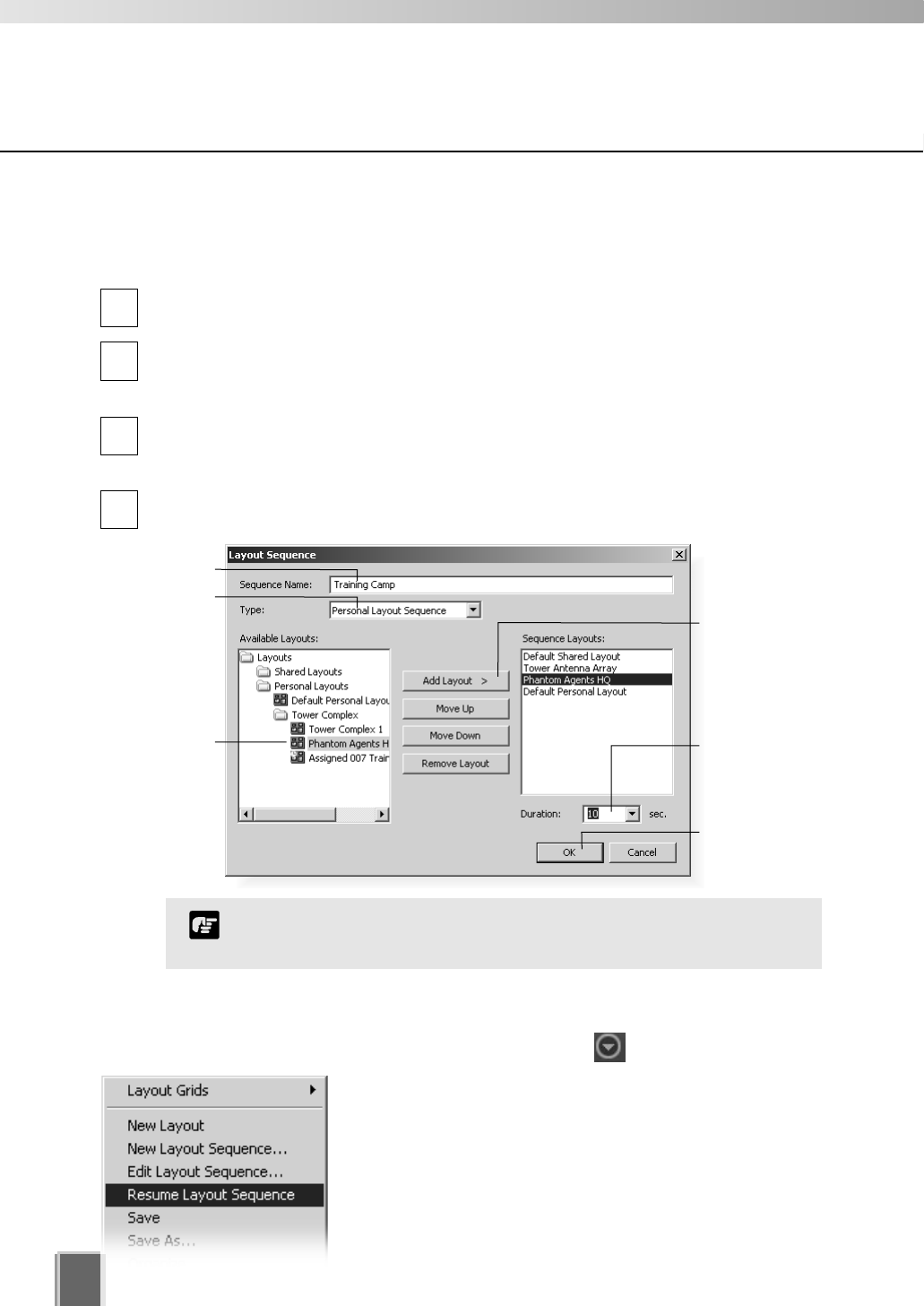
Managing Video Layouts
Arranging Layout Sequences
You can set up an automated sequence of shared and personal layouts to display in the
Viewing Area at set intervals.
From the Layout menu, select New Layout Sequence.... The Layout Sequence
dialog displays.
Enter a sequence name for the new layout sequence and choose a Type: of layout
sequence from the menu, Personal Layout Sequence or Shared Layout Sequence
(you can switch between the two as you add layouts).
Use the Add Layout > button to add layouts to the new sequence. Use the Move Up
or Move Down buttons to change the order of appearance of layouts or use the
Delete button to remove layouts.
In the Duration: menu, select a set duration of display time for each layout or enter a
custom time, overwriting the existing time.
1
2
3
4
Opening and running a layout sequence...
To start the layout sequence, select it from the Layout menu.
When a layout sequence is running, further options are
available in the Layout menu.
Click Edit Layout Sequence to change settings in the
currently-running layout sequence. The current
sequence will be indicated as [Paused].
Click Resume Layout Sequence to play the current
layout sequence.
Click OK to bring up
the Select destination
folder dialog.
Select or enter
a duration, from
1 - 9999.
Click Add Layout
to add a selected
layout from the
left-hand column.
Click on a
layout to
select it.
Enter a new name.
Select a layout type.
You cannot add an existing layout sequence to another sequence.
Note
118
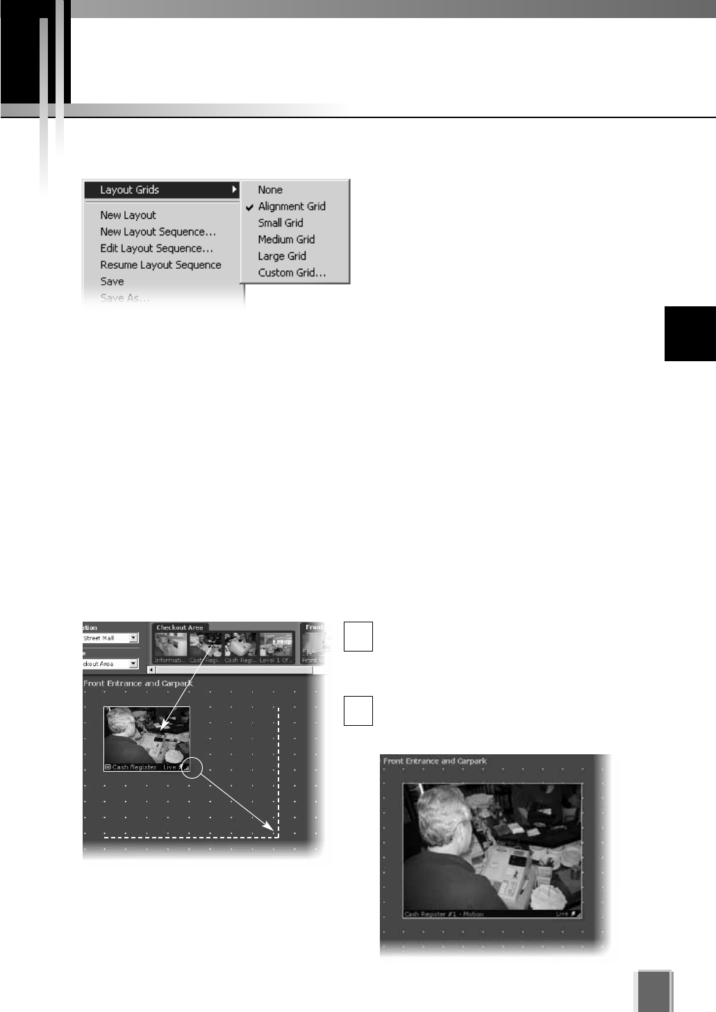
Working with Layout Grids
119
Working with the Alignment Grid
Select the Alignment Grid from the Layout Grids sub-menu. The Viewing Area
displays a grid of dots. When you place a Video Window, it ‘snaps’ to the grid
boundaries.
Drag, drop and re-size a Video Window
In the Camera Selection Area, click a
thumbnail image and drag its selection
boundary onto the Viewing Area grid. The
boundary will re-size.
Release the mouse button. The selection
will become a Video Window, and ‘snap’
into alignment along the grid closest to it.
1
2
You can customize your layouts by applying one of the following grids:
Alignment Grid - creates a grid of dots
where you can re-size Video Windows
of higher priority while reducing others
of lower priority.
Small Grid, Medium Grid and Large
Grid - creates a small, medium or large
grid where you can place Video
Windows in a tile-like manner. Use
smaller grids to place more Video
Windows or larger grids to view footage at a glance or from a distance. Video Window
sizes in grids can be increased to cover multiple grids.
Custom Grid - allows you to set uniform pixel dimensions for Video Windows.
Proportions are fixed, i.e. the shape is constrained to a 4 x 3 ratio. For example, if you
selected a horizontal of ‘615’, the vertical setting will become ‘461’ (and the grid is
scaled down).
To re-size the Video Window, click any
corner and drag the image outwards to
‘snap’ to a larger grid area.
n
10
Arranging and Saving Video Window Layouts
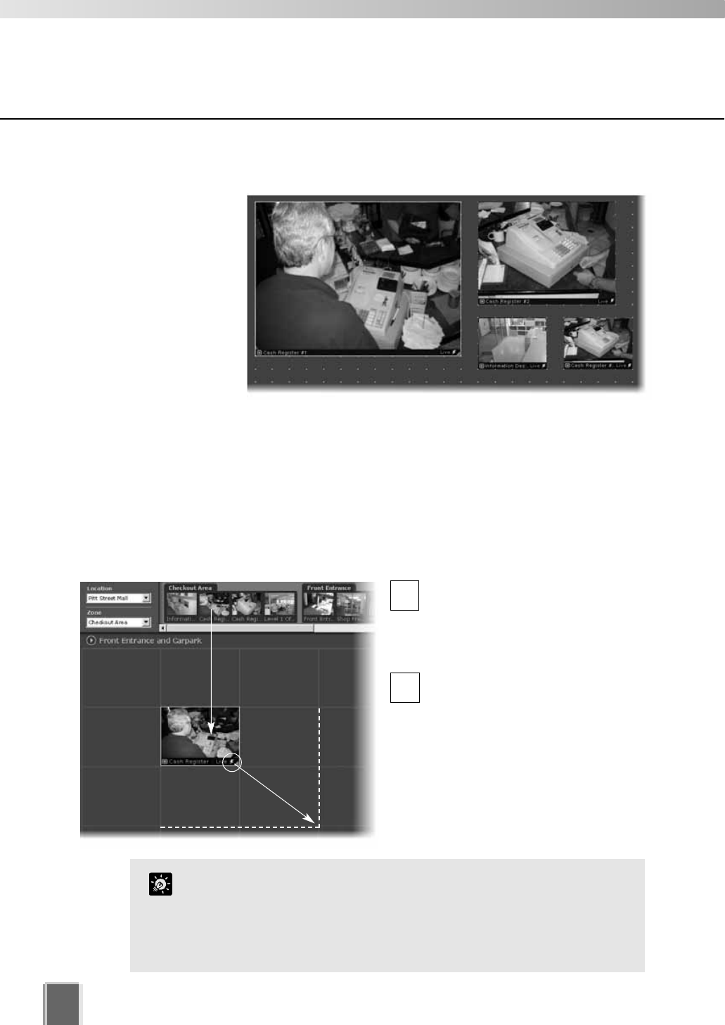
Working with Layout Grids
120
Working with Small, Medium and Large Grids
When you select Small Grid, Medium Grid or Large Grid from the Layout Grids
sub-menu, the Viewing Area displays ‘cells’ for Video Windows. These are boundaries
indicating a uniform size which is used to display Video Windows in a tile-like manner.
Drag a camera thumbnail image into a blank tile
In the Camera Selection Area, click
a thumbnail image and drag its
selection boundary onto the
Viewing Area grid. The boundary
will re-size.
Release the mouse button. The
selection boundary will become a
Video Window and ‘snap’ into
alignment along the grid closest
to it.
To re-size the Video Window, click any
corner and drag the image outwards to
‘snap’ to a larger grid area.
Create and align more Video Windows
Drag more thumbnail
images onto the Viewing
Area grid and re-size
them to suit your viewing
requirements as shown
in this example.
1
2
The Layout menu is also available by right-clicking anywhere in
the Viewing Area.
A Video Window can be increased in size to take up a number
of tiles, (for example 4 tiles, 9 tiles etc) so that Video Windows
of different sizes/priorities can be viewed.
Tip
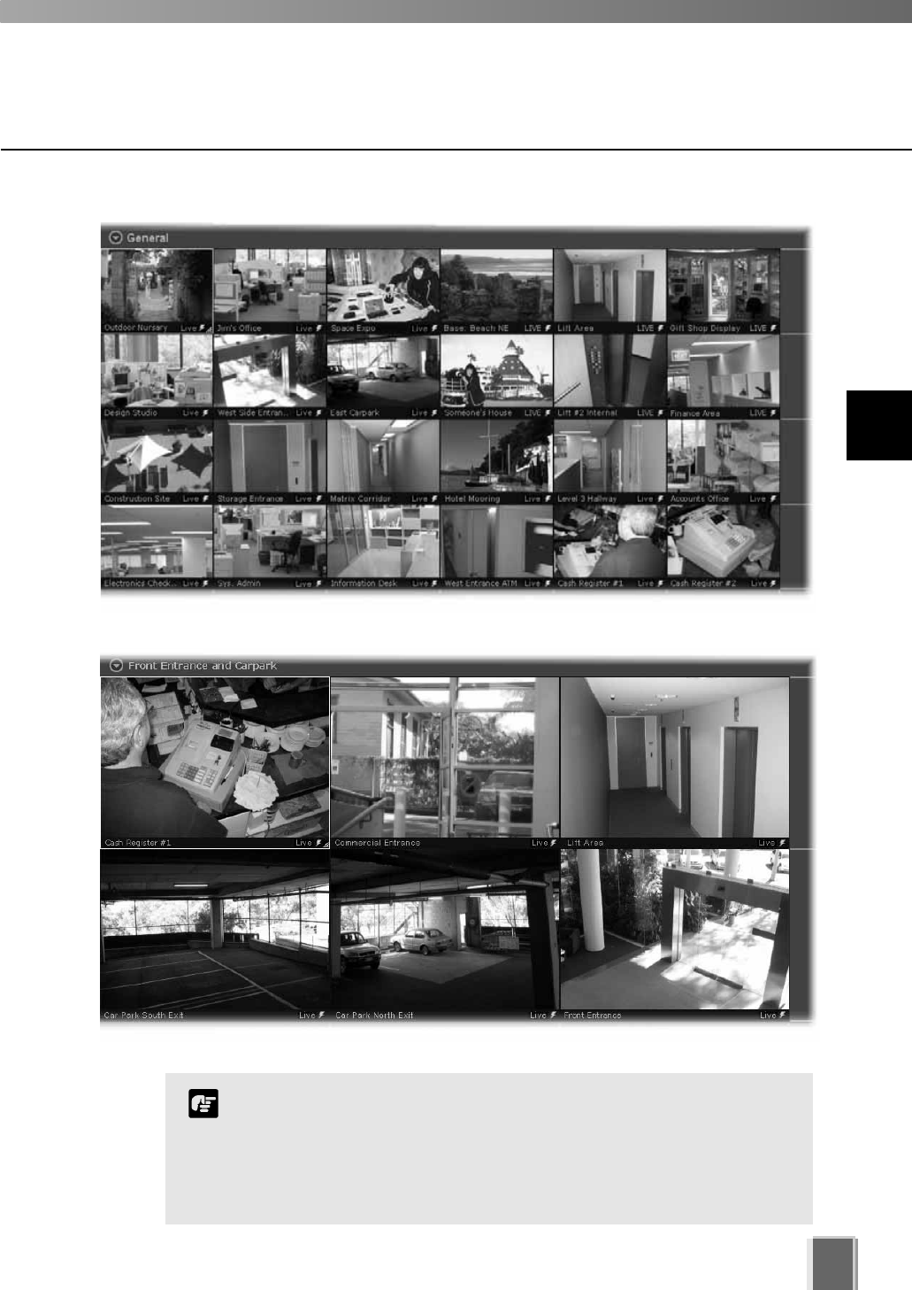
Working with Layout Grids
121
The Viewing Area with a Medium Grid could look like this:
The Viewing Area with a Small Grid could look like this:
A maximum of 16 cameras is recommended in the Layout Area.
Although you can add more, the number of Video Windows you can
display simultaneously will depend on your video card, the speed
of your computer, the maximum frame rate configured with Viewer
setting, the video size and video quality coming from the Camera
Server and the size of each Video Window displayed.
Note
10
Arranging and Saving Video Window Layouts
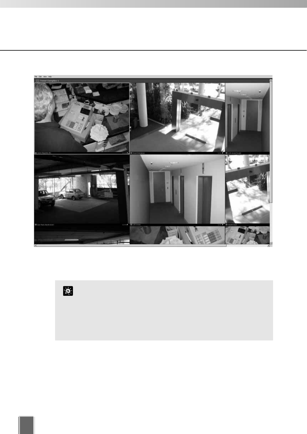
Working with Layout Grids
122
The Viewing Area with a Large Grid could look like this:
In this example, the Camera Selection Area and Timeline are hidden (tP. 124) and the
screen resolution is set to 1600 x 1200. If your screen resolution is set to 1280 x 1024, the
four Video Windows fully shown here will fill the screen area.
The Small Grid, Medium Grid and Large Grid are set to 160x120,
320x240 and 640x480 respectively. The PAL versions of the
VB-C50i/VB-C50iR, VB-C50FSi and VB-C50Fi provide images at
192x144, 384x288 and 768x576. If you want to display the images
at these full resolutions, use the Custom Grid size to set the grid
sizes accordingly. This is recommended when viewing a large
number of cameras as it improves the performance of the Viewer.
Tip
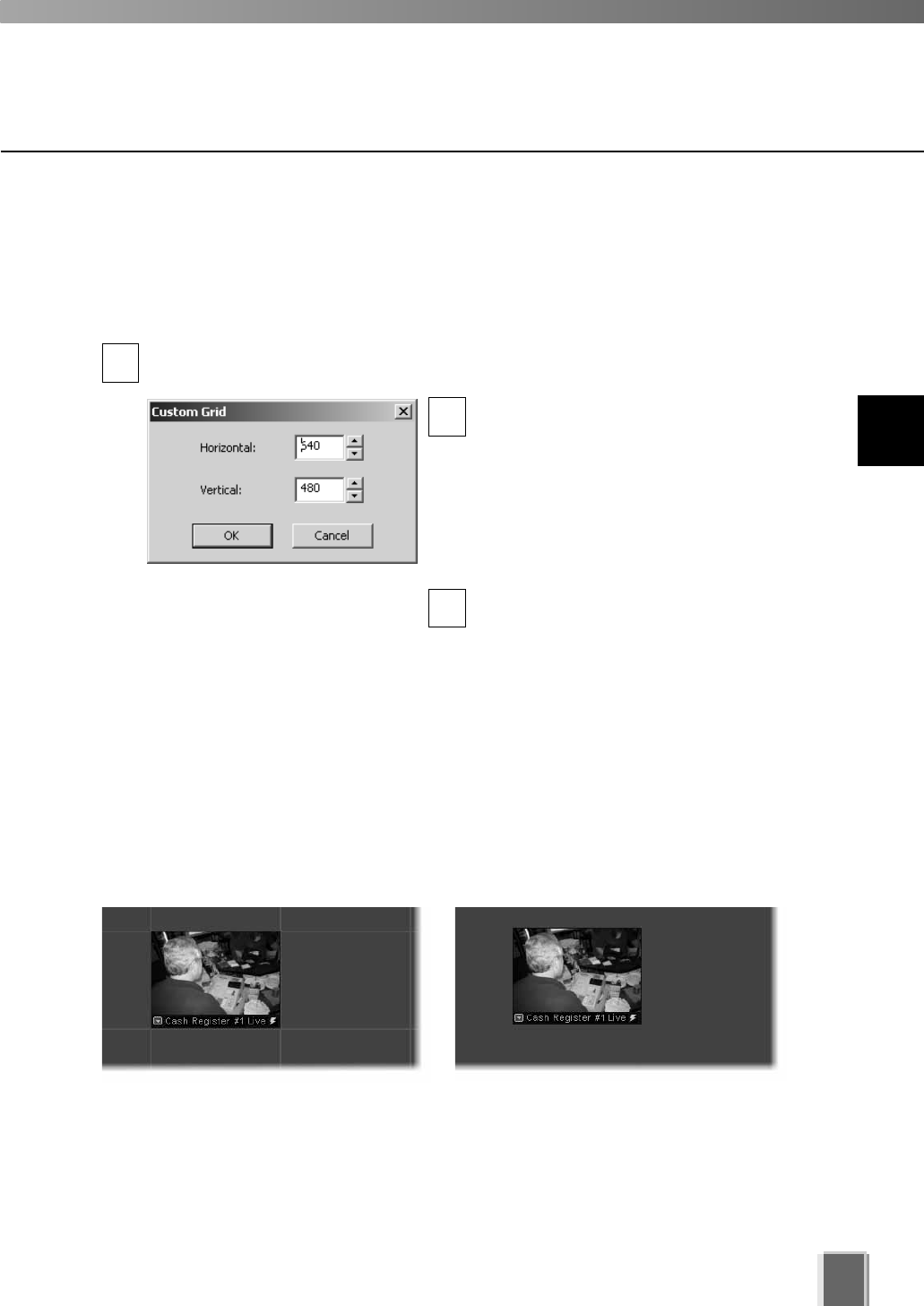
Working with Layout Grids
123
Removing a Layout Grid
You can easily remove a layout grid:
Open the Layout menu and select Layout Grids > None
In the Viewing Area, click the Layout button to bring up the menu and select
Layout Grids > None.
Alternatively, right-click anywhere in the Viewing Area to bring up the same menu.
Layout grid applied Layout Grids > None
Working with the Custom Grid
The Custom Grid feature allows you to set a custom-size for displaying Video Windows.
Set a custom grid
Select Custom Grid from the Layout Grids sub-menu. The Custom Grid dialog
appears. Values are given in pixels.
In the Horizontal or Vertical field, overwrite
the existing value with a custom value, or
use the up/down arrows to select a value.
When you adjust the value in one field,
you’ll notice the value change in the other
field. This is because the proportions of the
re-sized Video Window are constrained and
the dimensions are scaled accordingly.
Click OK to close the dialog. The grid will
re-size to your new settings.
1
2
3
10
Arranging and Saving Video Window Layouts
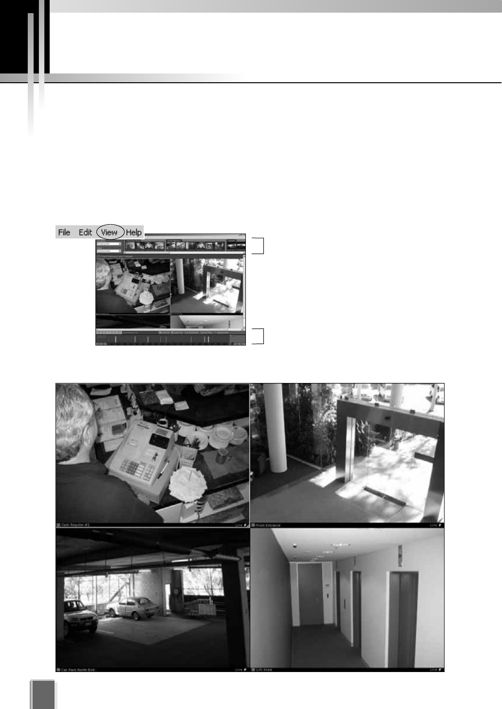
Hiding and Showing Task Areas
Using the View menu to hide and show Task Areas
The View menu allows you to show/hide task areas and other display elements in the
Viewer. When you unselect Camera Selector and Timeline and then select Fullscreen,
the result is a large area in the Viewer for displaying more Video Windows as shown below
in the Large Grid example. Pressing the Esc key returns the menu bar. You can also select
to hide Video Window Captions, the Camera Control and Live Events.
The number of Video Windows in the display size achieved is dependent on the screen
resolution. A higher resolution will result in more Video Windows displayed.
124
View tCamera Selector
View tTimeline
View tFullscreen (Large grid, 1280 x 1024). The Windows task bar is also hidden.

Chapter 11
Using the Timeline
and Viewing Events
This chapter shows you how to use the Timeline for live and pre-recorded
viewing as well as view and search events.
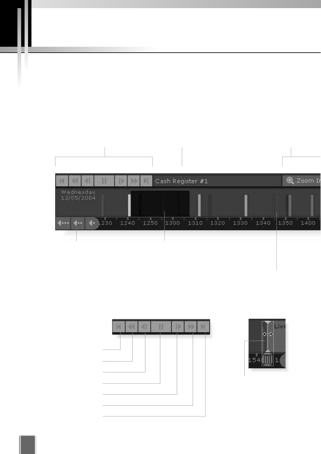
126
Timeline Overview
On the Viewing Screen, a timeline of past events associated with displayed cameras is
shown in the Timeline Area at the bottom of the Viewer as colored bars. Selecting a colored
bar moves the playhead to the event and the associated Video Window is switched to
playback mode.
Using the Timeline
Video Window Playback controls.
Previous Event.
Rewind.
Nudge Back.
Play/Pause.
Nudge Forward.
Fast Forward.
Next Event.
Camera name.
Click to scroll back hours,
by days or by weeks.
Darker areas indicate recorded
video for this period.
Events for non-selected cameras
(Video Windows) are indicated in
weaker colors as secondary events.
Playhead region.Playback controls.
Click in this area
of the Playhead
shaft and drag
to positions on
the Timeline.
Zoom in or out of the
Timeline to see events
in more or less detail.
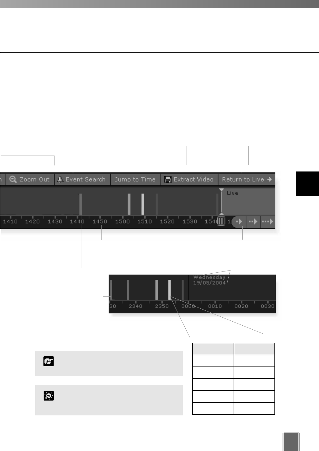
127
Monitoring Live Video in relation to the Timeline
When a Video Window is created from a camera thumbnail, video is seen live. The
Playhead (shown below, right) will be in a ‘live’ position and remain fixed as time scrolls to
the left underneath, representing the passage of real time.
Event display area. Day indicator.
Priorities are color-coded:
Click the time bar and drag to
scroll through the Timeline.
Events associated with
selected cameras (Video
Windows) in the Viewing
Area are indicated in
stronger colors as
primary events.
Extract recorded
video to save as
another file.
Click to jump
to a specified
date/time.
Click to
search for
past events.
Click to return the Playhead
to the Live position (if it has
been moved).
Click to scroll forward hours,
by days or by weeks.
Color Priority
Red Highest
Orange High
Yellow Medium
Light Green Low
Dark Green Lowest
11
Using the Timeline and Viewing Events
If no cameras are selected, all events
are shown as primary events.
Note
You can hide the timeline by
de-selecting ‘Timeline’ from the ‘View’
menu.
Tip
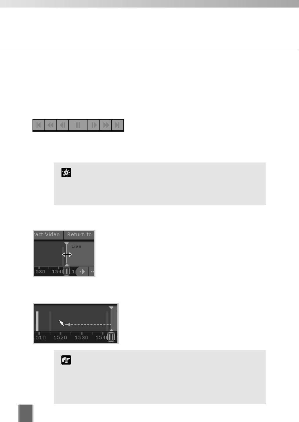
128
Using the Timeline
Using the Timeline to examine, play and extract video
You can view pre-recorded video by moving the Playhead control in the Timeline or
entering a timecode and jumping to it. Methods include:
Use the Playback Controls
Click the VCR-like controls to play, rewind, fast
forward, nudge or move to previous and next events
(as detailed on page 126).
The fast forward and rewind speeds change by 1x,
2x, 5x and 10x each time you click the buttons.
Drag the Playhead to a new time
Click and drag the Playhead shaft to another location. When you
move the Playhead, you are effectively controlling all Video
Windows that have been selected.
Click in the Event Display Area of the Timeline
Click in the Event Display Area of the Timeline. The
Playhead will move to that location and playback of
recorded video commences from that time.
Playheads of different cameras can be controlled separately, that
is, you can rewind video in one window to a defined time and then
select a different Video Window and rewind it to another time. This
is ideal for comparing the same or different cameras at different
times.
Tip
When you choose to play back video, the video is played over a
network, therefore the response and smoothness of the play
back will depend on network traffic and other properties of the
network.
The time displayed on the Timeline and in the Live Events
window is the local time at the Viewer.
Note
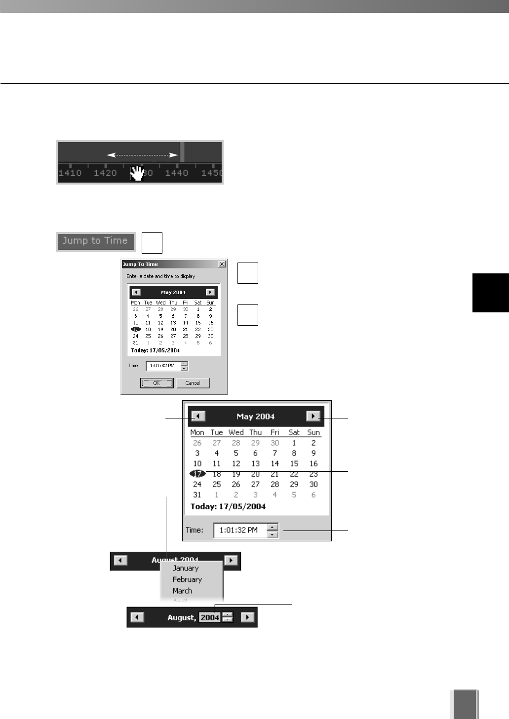
Move your mouse pointer over the time bar and it
becomes a hand. Click and drag to the left or right
to move back or forward in time. You can only scroll
right to the current time, or ‘live’ time.
129
Using the Timeline
Jump to time
Select a Video Window and click the Jump to Time button.
The Jump to Time dialog opens. Select a
day and/or time. You cannot select dates
beyond ‘today’s date’.
Click OK when done.
The Playhead and Timeline will move to the
time selected. If no Video Windows are
selected, only the timeline is moved.
Using the calendar is shown below.
Click and drag the time bar to move through the Timeline...
Click to scroll back
through the months.
Alternatively, click the
current month and a month
selector will appear.
To select another year, click
the current year and scroll
down or back up, using the
up/down arrows.
Click to scroll forward
through the months.
Click a day to highlight
it, then click OK to bring
up that day in the
Timeline.
Click up/down arrows to
select a time or click
each time segment and
overwrite existing value.
2
1
3
11
Using the Timeline and Viewing Events
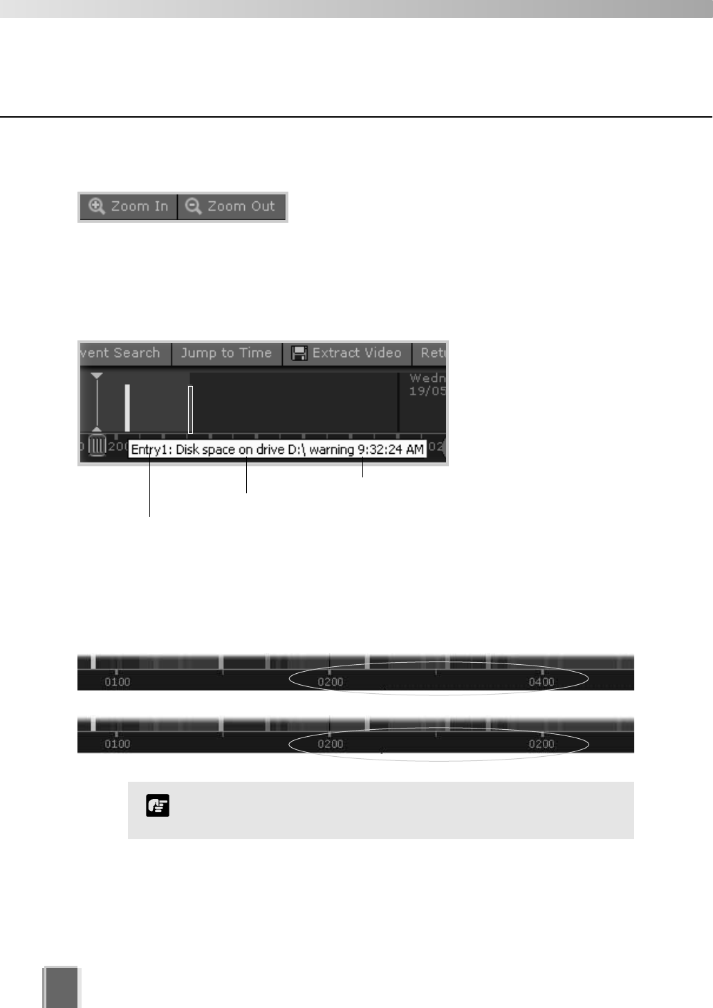
130
Using the Timeline
Daylight Savings Indicator
When normal time has changed to Daylight Savings time, time that is skipped is displayed
in the Timeline as missing. When gaining time (rewinding the clock back from 02:00 to
01:00), the extra time is duplicated.
Where Daylight Saving changes have occurred, the Timeline
display is still continuous. Only the labels are affected.
Note
Skipped Time
Duplicated Time
Zoom in and out of the Timeline
Click Zoom In to zoom into a time period in the Event
Display Area. The Timeline will expand and you can
examine time in more detail.
Click Zoom Out to zoom outwards from the Timeline.
Click an event to select it
When you click an event to
select it, the associated
Video Window will display
the event(s).
To get information about
events move your mouse
pointer over the event.
Move mouse over event to get details.
Type of event
Camera Name
Time of event
Click
event to
select it.
A time segment with darker
color indicates that recorded
video exists for that period.
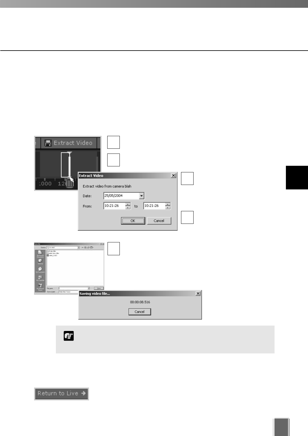
131
Using the Timeline
When you have finished, click ‘Return to Live t’
When you have finished viewing pre-recorded video, click Return to
Live tto return the Playhead to the live position in the Timeline.
Extracting video to save to another location
A portion of video can be saved to another location if required. Files are automatically saved
as QuickTime .mov format and can be viewed in a QuickTime player or any other player
that supports .mov files. A maximum of one hour of video can be extracted at a time. If you
do not have a QuickTime player installed, visit http://www.quicktime.com for a free download.
Select a Video Window and time period then click ‘Extract Video’
Click a Video Window to highlight it, then click and drag a
time period for it in the Timeline.
Click the Extract Video button. The Extract Video dialog
opens.
In the Date: field, click each
segment and overwrite with
desired date. Alternatively
click the down arrow to use
the calendar.
In the From: and To: field,
click the time segments and
overwrite with desired time,
or use the up/down arrows.
Click OK. The Save As dialog opens. Browse to a
suitable folder in which to save the extracted video. Enter
a File name and click Save.
The Saving video file... dialog momentarily opens. It
indicates the save in progress before closing.
You must select only one Video Window to extract video.
QuickTime player version 6.5.1 or later is recommended.
Note
3
5
1
2
4
11
Using the Timeline and Viewing Events
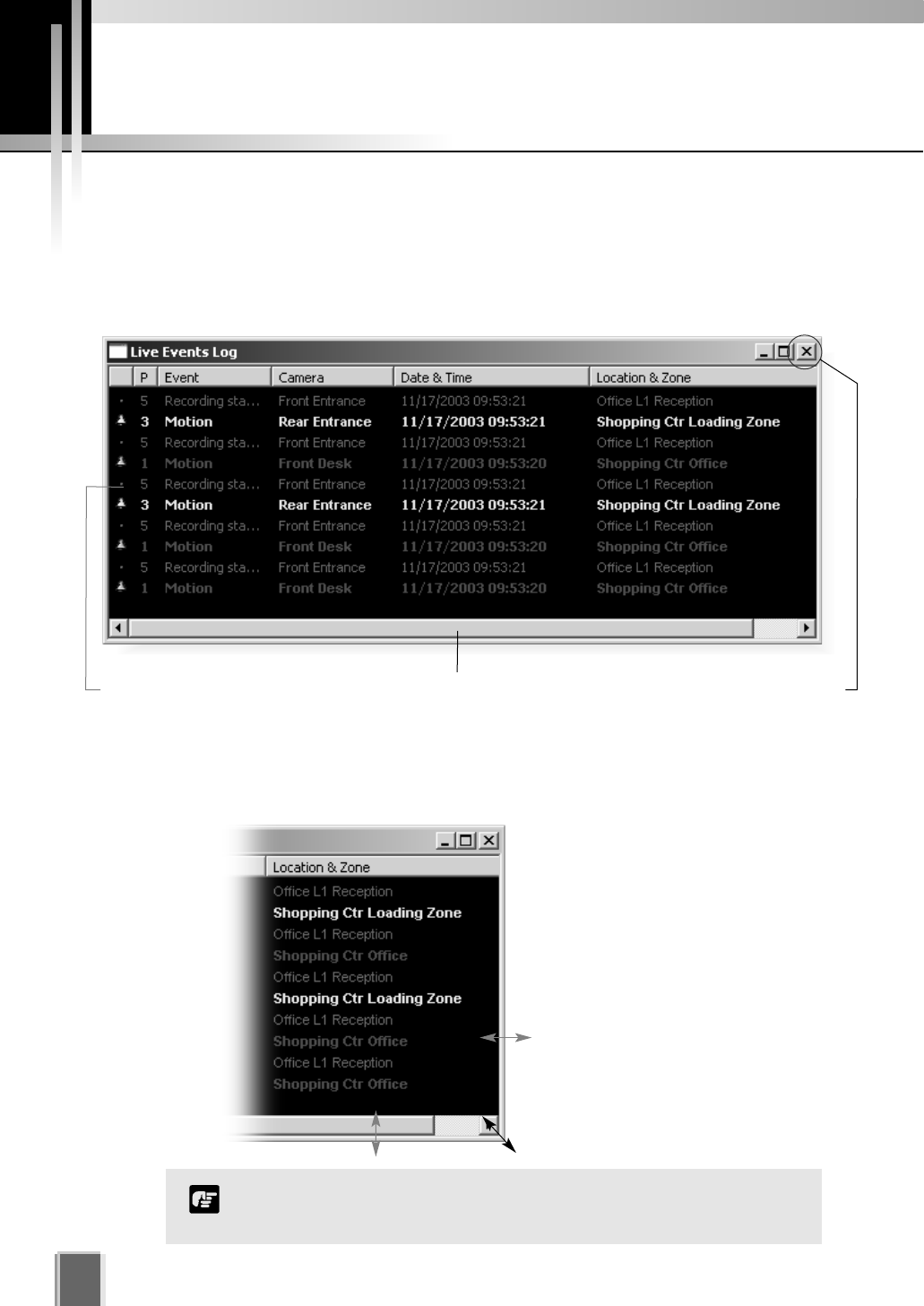
Viewing and Searching Events
132
About Live Events
The Live Events Log displays events that have occurred with one or more cameras after
the Viewer has been launched. Events are color coded according to priority. The Live
Events Log opens automatically when you launch the Viewer, if left open in a previous
session.
Re-size the window to a custom size
Click the corners or edges and drag
the window out to a new size.
Release the mouse button.
When you launch the Viewer again,
the Live Events Log will retain the
size you selected.
The bell icon is replaced by a ‘dot’ icon when
the event is acknowledged by double-clicking.
Click and drag scroll bar to view events. To maximize,
double-click title bar or click the maximize icon.
Only the most recent 200 events are shown in the Live Events
Log.
Note
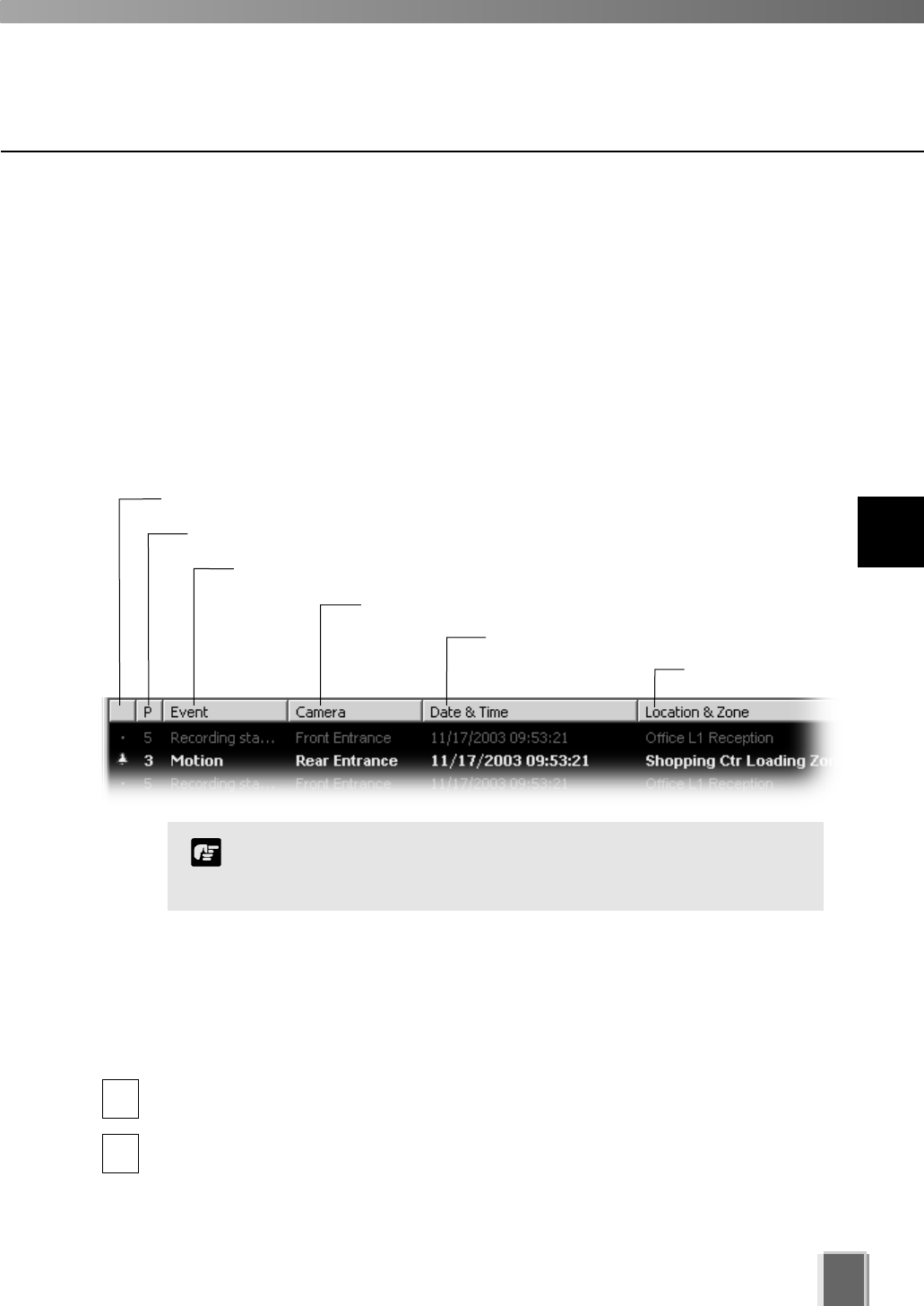
133
Display the Live Events Log (if not displayed)
To display the Live Events Log if it is not displayed:
Select View > Live Events
From the VK-64 Menu Bar, select:View > Live Events.
The Live Events Log opens. Once selected, the menu item will be ticked next time you
display it.
Acknowledgement status
Priority of the event
Event type that has occurred
Camera name where event occurred
Date and time of event
Location and Zone
Event priorities and notification settings are configured in the
Configuration and Preferences Screen. You must have
Administrator privileges in order to modify priorities.
Note
To acknowledge and view an event
A new event entry will appear at the top of the Live Events Log list and will flash for a
defined period if configured. If Operator Acknowledgement is required, the event will flash
indefinitely if not acknowledged.
In the Live Events Log, double-click on the event to acknowledge it and view it in its
associated Video Window.
In the bottom right corner of the Viewer, click Return to Live twhen you have
finished viewing the event. The Video Window will return to live viewing.
1
2
Overview of Alert Parameters
11
Using the Timeline and Viewing Events
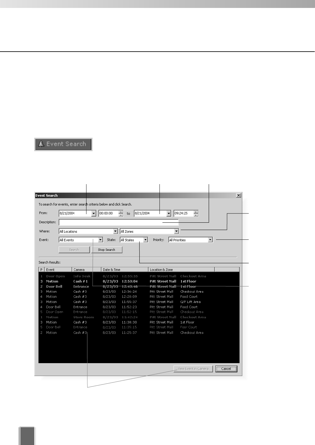
134
Viewing and Searching Events
Searching Events
If you have multiple events, you can initiate a search for a particular event via the Event
Search dialog. Note that you cannot acknowledge an event from this dialog.
To launch the Event Search Dialog:
Click the Event Search button
On the Timeline, click the Event Search button.
The Event Search dialog opens.
Select a
Priority.
Select a
state of
event.
Select a
type of
event.
Select a
Location
and Zone.
Enter a search start
date and time.
Enter a search end
date and time.
Enter a keyword for
particular events.
Search Results area
Double-click an event to view it in the Video Window, or click an event
to highlight it and then click the View Event in Camera button to view it.
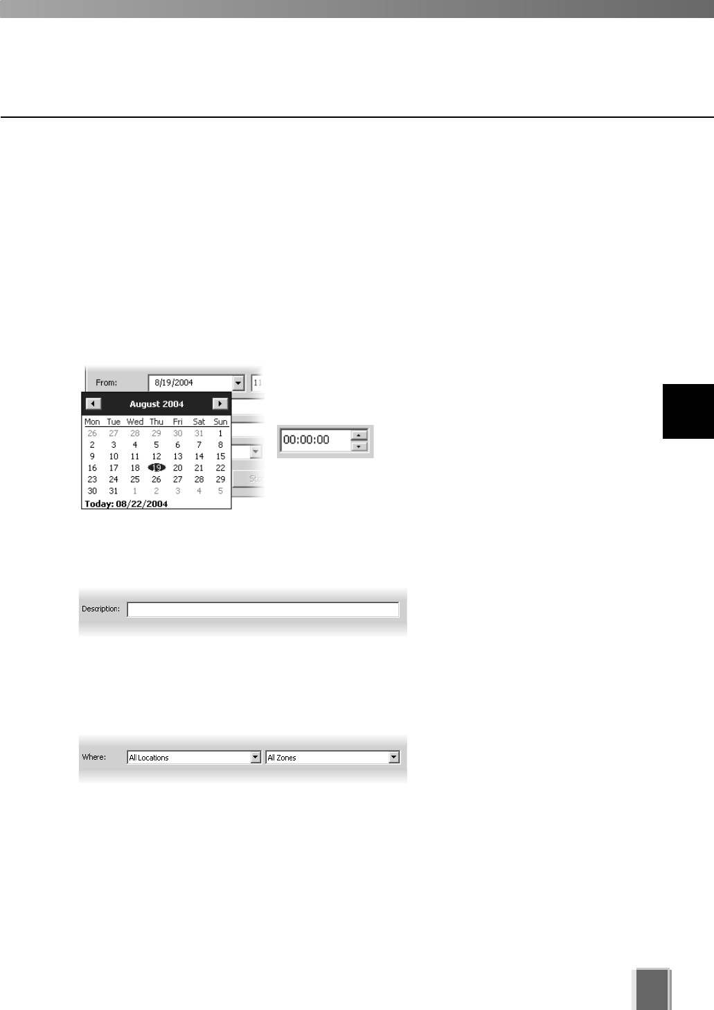
135
Viewing and Searching Events
Selecting Criteria for Searching
When you initiate a search, certain criteria can be specified such as Priority, Location and
Zone on the network, a date range when the event may have occurred and a time period.
To initiate a search:
Step 1: Select a date and time range to search
Click in the From: and To: date panels and overwrite the existing entries for
month/day/year and time. Although you can select earlier periods, you can only view the
earliest recorded event and you cannot go past today’s date.
Alternatively, click the down arrow next to each date panel
to bring up the calendar. Click off the calendar to close it
again.
In the Event Search dialog, you can
also scroll through time using the
up/down arrows. Click an hours, minutes
or seconds segment to highlight it and then click the up or
down arrow.
Step 2: Select an event keyword
In the Description: field, enter a
keyword such as, ‘deleting’,
’recording’, ‘frames’, etc. Found
events will be based on your text
entry.
Step 3: Select a Location and Zone to search
From the Where: fields, select a
Location and Zone from the
drop-down lists. Only events within
the location will be selected.
11
Using the Timeline and Viewing Events
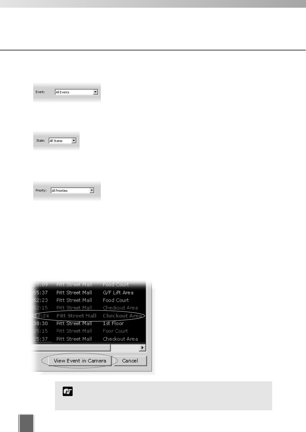
136
Step 7: Click the Search button
When you have entered the day and time range, click the Search button to initiate the event
search. Events that are found will be listed in the window below. If necessary, stop a search
at any time by clicking the Stop Search button.
Viewing found events
To view an event in a Video Window, click
the event to highlight it and click View
Event in Camera to view it in a Video
Window.
You can also double-click an event to view
it in a Video Window.
Clicking Cancel stops any searching and
closes the dialog.
Viewing and Searching Events
When you have finished viewing an event in a Video Window, click
the ‘Return to Live t’ button in the Timeline to return the Video
Window to live viewing.
Note
Step 6: Select a Priority
Select a Priority from the drop-down list.
Step 4: Select a type of Event
Select a type of Event from the drop-down list.
Step 5: Select a State
Select a State for the event, whether it was On or Off during the
period. Alternatively, select All States.

Appendix A
Troubleshooting
VK-64
This appendix outlines possible solutions to VK-64 operating issues.

Troubleshooting VK-64
138
Viewing Screen and Video Windows
The following issues may arise during normal operation of the Viewer:
Some of the thumbnails are not showing in the Camera Selection Area.
Situation You currently do not have enough camera thumbnails on display to make
the scrollbar appear, however some of the thumbnails that were displayed
earlier are no longer visible.
Solution Most likely you have selected another Zone or Location from the
drop-down menu that is further down the list and the thumbnails have
scrolled to the left to show the selected Zone. Click the Zone drop-down
menu and select the zone at the top of the list. Thumbnails associated with
that zone will be displayed, i.e., groups of thumbnails will shift to the right.
Cannot Pan, Tilt or Zoom the camera in a Video Window.
Situation You clicked a Video Window to get camera control but the controls do not
appear.
Solution You need to double-click in the Video Window to bring up the controls or
select Get Camera Control from the Video Window menu. Alternatively,
check if you are actually looking at recorded video (the title bar will be
gray, not black).
The Record Now feature is gray in one Video Window menu, however it is enabled
in other Video Window menus.
Situation You click to bring up the Video Window menu and Record Now is gray
(disabled) but other Video Windows have the function enabled.
Solution When the camera was configured, it was most likely set to Do not Record.
If you need the camera set up for recording, see your System
Administrator or refer to the configuration chapters in this manual.
Layouts set up by another user cannot be seen.
Situation In the Organize Layouts & Layout Sequences dialog, you click in the
Personal Layouts folder in order to open a Layout created by another
user.
Solution Layouts saved in the Personal Layouts folder cannot be seen by other
users. If the Layout created by a user with Operator status is required for
all users to view, it should be saved to the Shared folder. See your System
Administrator.
You may encounter the following situations while using VK-64. If you encounter difficulties
that are not discussed in this section, please consult your System Administrator.

139
A
Appendix A -Troubleshooting VK-64
Live and recorded video is not good quality (this does not relate to Resolution).
Situation In a Video Window, the live quality may be different from another Video
Window and the recorded video (when you play back video) is also not
good quality.
Solution The quality of recorded and live video cannot be changed in VK-64. The
reason why the quality may be better in one Video Window and not
another is due to the Camera Server settings and quality can be changed
in the admin screens of the Camera Server to a higher setting. See your
System Administrator.
Live Video Windows in the Viewing Area are jerky.
Situation In the Viewer Area of the Viewing Screen, live video appears jerky.
Solution The Live Video Viewing Settings have a low frame rate set. The frame rate
can be modified by opening the Configuration and Preferences screen and
selecting the Viewer Settings tab. Select a suitable frame rate that does
not affect the performance of the Viewer, i.e., lower frame rates are ideal if
you have many Video Windows open in the Viewing Area.
No presets, sensors or external devices appear for the camera.
Situation You have opened the Video Window menu for a particular camera and no
presets are available and/or the menu items are disabled.
Solution You must enable the menu items if they are disabled by selecting Get
Camera Control from the Video Window menu. Menu items should then
be enabled. If no preset camera angles, sensors or external devices are
available it means that they have not been set in the admin screens of the
particular Camera Server.
Cannot access cameras from another Storage Server.
Situation In the Configuration and Preferences Screen, Camera Summary window,
you have attempted to add another Storage Server.
Solution You do not have an account set up on that Storage Server. See your
System Administrator.
Free disk space gets low after the Viewer has been in use for a long period.
Situation After launching the Viewer, you have displayed live and recorded video for
a long period and free disk space gets low.
Solution If you are using anti-virus software, communication between Viewer and
camera servers is being recorded and that file may be several gigabytes in
size. Please alter the anti-virus software settings to eliminate the Viewer
from virus scanning targets.

Troubleshooting
140
After running a Layout Sequence for some time, it is no longer possible to
connect to some of the cameras.
Situation Immediately after launching the Layout Sequence, live images from all the
cameras can be displayed, but after several minutes or hours, the video from
a number of cameras is no longer displayed.
Solution When a large amount of Video Windows is displayed in a single layout and
layouts are configured to switch at short intervals, the resources needed for
communication become insufficient and the problem described above occurs.
For example, this can happen where a layout showing Video Windows from
20 cameras is switched at 10-second intervals. Reduce the number of
cameras displayed in the layout or set a longer switching interval.
Timeline
The following issues may arise during normal operation of the Timeline in the Viewer:
The Playback controls are inactive.
Situation You attempt to click any of the Playback controls and nothing happens.
Solution Move the Playhead away from the Live position. Playback controls will then
be active. A Video Window needs to be selected for playback. Also, the
nudge buttons and the Extract Video button are only enabled when only
one Video Window is selected.
Extracting Video
The following may arise during video extraction:
Cannot save video as no data could be found.
Situation An error message appears if you have attempted to extract video when no
video can be found in the selected segment.
Solution Ensure the segment of video has recorded footage.
Scheduling and Recording
The following schedule and recording-related issues may arise during normal operation
of VK-64:
Cannot initiate a Record Now on a camera.
Situation You have selected a Video Window in which to initiate Record Now
but the menu option is not available.
Solution In the Configuration and Preferences screen, Edit Camera Server dialog,
‘Do not Record’ is probably set up for the camera. Change the option to
record to the Storage Server.

Troubleshooting
141
Cannot configure camera not to record.
Situation You have attempted to modify a camera and set ‘Do not record’ in the Edit
Camera Server dialog. A message appears stating the camera is already
set up without recording.
Solution In the Camera Server list of the Storage and Camera Server Summary
screen, Locations / Zones tab, the selected camera will have more than
one listing. Click the listing which has an associated Storage Server listed
beside it and then click Remove Camera Server. Make sure you save
your changes to permanently remove the deleted camera.
Storage Server free disk space is extremely low.
Situation Storage server disk usage is far in excess of the calculated level (tP.145)
and there is little free space.
Solution When the camera server video quality is set high, there is a large amount
of data per frame. Also, if you are using anti-virus software, communication
between Storage Server and camera servers is being recorded and that
file may be several gigabytes in size. Please alter the anti-virus software
settings to eliminate the Storage Server from virus scanning targets.
Connection Issues
The following connection-related issues may arise during operation of the Viewer:
Cannot connect to camera.
Situation In the Viewer the screen has gone black and a message appears
stating ‘Could not connect to camera’.
Solution A number of solutions could apply. The network could be down, the
physical connection to the Camera Server could be broken or the camera
may not be powered.
Cannot connect to Master Storage Server.
Situation You have launched the Viewer and a connection to the Master Storage
Server error message appears.
Solution The specified Storage Server is probably not on the network. If it is, make
sure the computer it resides on is powered and the Storage Server
is running. On the Storage Server computer, open the Storage Server
Configuration utility. If the Storage Server is not running, click the Start
Storage Server button (tP. 22).
A
Appendix A -Troubleshooting VK-64

Troubleshooting VK-64
142
The Configuration and Preferences screen takes a long time to open.
Situation When you switch from the Viewing Screen to the Configuration and
Preferences screen, a Please wait... message appears and remains on
screen for a long time.
Solution You may have a lot of cameras to disconnect from as waiting time
is dependent on disconnecting from each camera/Camera Server on the
network. Remove non-essential or low priority cameras from your Viewing
Screen.
Fails to connect to Storage Servers when you switch to the Configuration and
Preferences screen.
Situation You have switched to the Configuration and Preferences screen and an
error message appears stating a failure to connect to a particular Storage
Server (name), even though it can still connect to the Master Storage
Server.
Solution Access to the Storage Server may be denied for a number of system
reasons or the Storage Server computer may not be powered. A network
error could also be responsible. See your System Administrator.
Configuration Issues
The following configuration issues may arise during operation of the Viewer:
Cannot switch to the Configuration and Preferences screen.
Situation You have attempted to switch from the Viewing Screen to the Configuration
and Preferences screen and an error message appears.
Solution You have Operator status. Only Administrators can access the
Configuration and Preferences screen.
Cannot see cameras on the Camera Summary window.
Situation You are viewing a list of cameras on the Camera Summary window and
some cameras are not visible.
Solution Only cameras associated with the item selected on the Storage Server tab
or the Locations/Zones tab will be shown. Also, if you have the Storage
Server tab displayed, cameras configured as ‘Do not record’ will not be
shown.

Appendix B
Example Operating
Conditions
This appendix outlines example Storage Server and Camera Server situations.
Example Operating Conditions
144
This section provides information that may help you in specifying and configuring a
computer to use as a Storage Server.
Frame Sizes
VK-64 receives each image from a Camera Server as a JPEG image. The size of the
images varies depending on the configuration of the Camera Server (the settings for Quality
and Resolution) and the complexity of the actual image.
The following tables give some typical frame sizes (in kilobytes) for various quality and
resolution values from a VB-C50i and VB150. However it is important to note that,
depending on the complexity of the image, the frame sizes may vary substantially from
those listed in the tables. For example, images of an empty corridor would typically be
smaller than these values and images of a very intricate pattern such as a crowded
shopping mall would typically be larger than these.
Example of frame sizes with VB150
Example of frame sizes with VB-C50i
160x120 320x240 640x480
30
40
50
70
80
90
3.8
4.4
5.0
6.6
8.1
11.8
11.1
13.3
15.1
20.3
25.4
37.3
36.4
43.4
49.2
67.0
85.5
128.0
Every installation of VK-64 is different (due to different usage
requirements and different hardware specifications) and the figures
provided in this section are an indication only. These figures are
not intended to apply to every installation of VK-64.
Note
Values are in kilobytes.
Resolution (captured with NTSC mode)
Quality
160x120 320x240 640x480
30
40
50
70
80
90
3.5
4.2
4.7
6.3
7.9
11.7
10.4
12.4
14.1
19.1
24.0
35.2
18.9
22.7
25.8
34.6
43.3
63.1
Resolution
Quality
*The data size mentioned above is an indication only, which will vary in accordance with the
subject being captured. Please be sure to confirm under the actual installation conditions
before starting operations.
* Please note that data size may increase enormously when video quality is set to 100.
145
B
Appendix B - Example Storage Server Conditions
Bandwidth and Disk Space
The bandwidth and disk space requirements for using VK-64 can be determined by
calculating the recording frame rate, number of camera servers and frame size.
For example, a system using:
16 camera servers (VB-C50i) each recording continuously at 5 fps,
With each camera set to Medium Size for video capture and Quality set to 50, and
Frame size* per single frame is approximately 15 KB...
...requires a bandwidth for a single camera server of approximately:
600Kbps (15KB x 8bit x 5fps).
In this case, the total bandwidth for 16 camera servers would be approximately 9.6Mbps
(600Kbps X 16 cameras = 9600Kbps).
*The frame size figure shown above is an example. Please note that the actual frame size
varies depending on the video content.
The recording throughput required by the Storage Server is not the
total traffic on the network, as this does not include viewing of live
cameras and playback of recorded video by Viewers, and any other
network traffic.
Note
The above figure can also be used to calculate the hard disk requirements used by the
Storage Server. For the above configuration, if the 16 Camera Servers are being recorded
continuously at 5 frames per second all day, every day, the disk requirements would be
approximately 100GB per day (15KB x 5fps x 16 cameras x 60 seconds x 60 minutes x 24
hours = 103680000KB per day).
However, when determining hard disk sizes it is important to take into account that there
needs to be some ‘overhead’. For example, if the [Maximum file size/duration] (tP. 23) is
configured to 1024MB (1GB), a video file of 1GB is created per every single camera
server. Therefore when the Storage Server deletes old recorded data, the full 1GB will be
deleted according to the disk space management description (tP. 24) and disk space
management operating examples (tP. 146); with 16 Camera Servers, totalling 16GB.
So, for example, the above-mentioned hard disk requirements could be increased by 16GB
to deal with this situation.
As the above figures are for continual recording, the hard disk usage can be substantially
reduced by using sensor-based or motion-based recording and/or by limiting recording to
certain times of the day or days of the week. The disk usage that would result from
applying these settings would depend greatly on the frequency of occurrence of such
sensor and motion events and the number of defined days and times therein.
For the above figures please note that the bandwidth is calculated as 1000Kbps = 1Mbps,
and the disk size as 1024KB = 1MB.
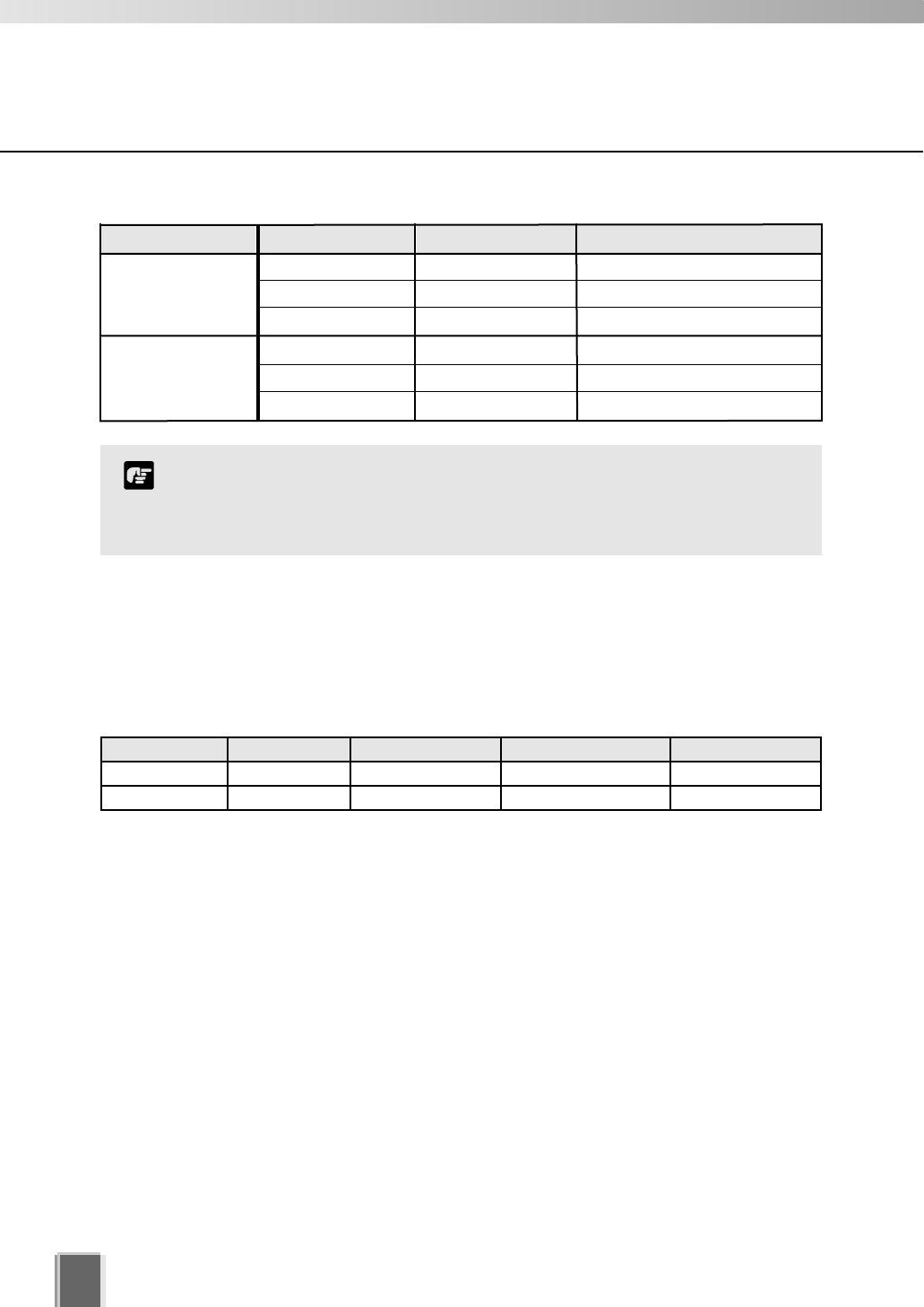
146
Example Operating Conditions
The figures in the above table are an indication only. The frame sizes will
vary according to the scene captured by the camera, and thus the required
hard disk capacity will vary. Please be sure to confirm under the actual
installation conditions before starting operations.
Note
Example of Hard Disk Capacity (6 units of VB-C50i, 1fps, retention period of 30 days)
Resolution Quality Frame Size (KB) Required HDD Capacity (GB)
320x240
640x480
30
50
80
30
50
80
11.1
15.1
25.4
36.4
49.2
85.5
164.6
224.0
376.7
539.9
729.7
1268.1
Captured with NTSC model.
Disk Space Management
The following are specific and operative examples describing how the Storage Server
manages its disk space.
Example: Storage Server has two disk drives; C and D. Specify [Maximum disk space used]
(tP. 23) as tabled below. 19 camera servers are used for recording per drive. It is assumed
that [Low disk space notification threshold] (tP. 23) is specified as 10%.
Disk Drive Disk Capacity Free Disk Space Max. Disk Space Used Camera Server No.
C Drive 100GB 50GB 40GB 19 units
D Drive 200GB 200GB 200GB 19 units
The Storage Server manages its disk space according to the following rules:
Low Disk Warning Level
When case 1 or 2 below is satisfied, the Storage Server generates event notification.
1) When the Storage Server disk space used exceeds the following value:
[Setting value of Maximum disk space used] * (100 - [Low disk space notification
threshold]) /100
For example, if the [Low disk space notification threshold] is set to 10%, event
notification is generated at the time when the free disk space is reduced to 10% or
below of the setting value of Maximum disk space used.
2) When free disk space falls below the following value:
[Disk capacity] * [Low disk space notification threshold] /100
If the Storage Server is the only application running on the disk, observe case 1.
If other applications may write to the same Storage Server disk, observe case 2.
Even if the Storage Server uses only a small amount of disk space, event notification may
be generated according to case 2 when other applications use the free disk space.
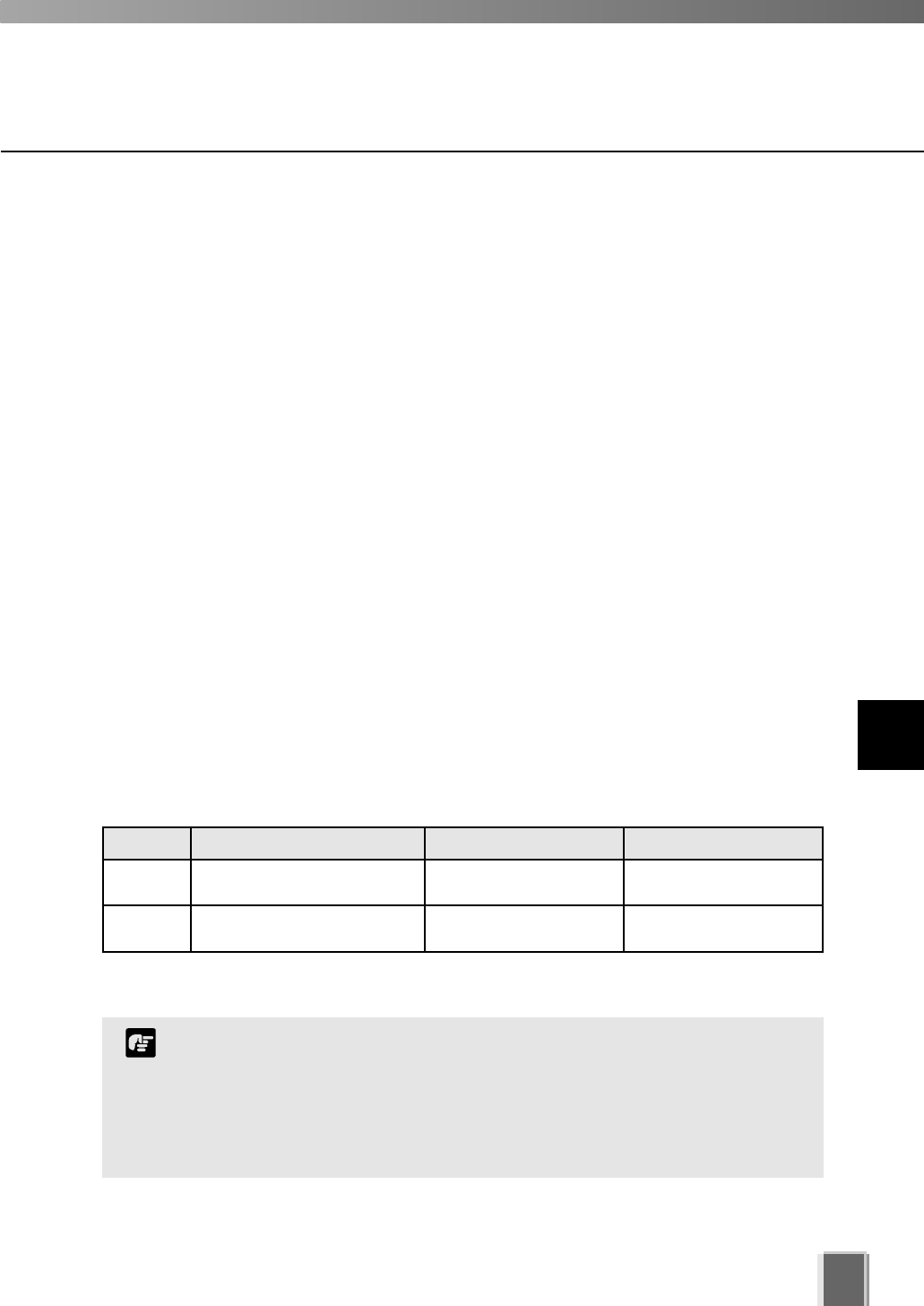
147
Example Operating Conditions
B
Appendix B - Example Storage Server Conditions
Threshold Level
When case 1 or 2 below is satisfied, the Storage Server begins deleting video files, starting
with the earliest ones. The Storage Server keeps recording video. At the same time, the
Storage Server generates event notification.
1) When the Storage Server disk space used exceeds the following value:
a. If [Setting value of Maximum disk space used] is 384MB or more,
[Setting value of Maximum disk space used] - 96MB
b. If [Setting value of Maximum disk space used] is 384MB or less,
[Setting value of Maximum disk space used] * 3/4
2) When free disk space falls below the following value:
(Number of camera + 1) * 32MB + 96MB
Limit Level
When case 1 or 2 below is satisfied, the Storage Server stops recording video. At the
same time it generates event notification. Even though the Storage Server has started
deleting video files when the ‘Threshold Level’ is reached, recording will stop at the time
when the ‘Limit Level’ is achieved.
Storage Server resumes recording when the free disk space rises above the ‘Limit Level’.
1) When the Storage Server disk space used exceeds the following value:
a. [Setting value of Maximum disk space used]
2) When free disk space falls below the following value:
b. (Number of camera + 1) * 32MB
The following is a table of values for each level calculated based on the above examples.
Calculations referenced by 1) refer to disk space used by the Storage Server.
Calculations referenced by 2) refer to disk space remaining.
Disk Drive Low Disk Warning Level Threshold Level Limit Level
C Drive 1) 40GB * (100-10) / 100=36GB
2) 100GB * 10 / 100=10GB
1) 40GB-96MB=39.904GB
2)
(19+1) * 32MB+96MB=736MB
1) 40GB
2) (19+1) * 32MB=640MB
D Drive 1) 200GB * (100-10) / 100=180GB
2) 200GB * 10 / 100=20GB
1) 200GB-96MB=199.904GB
2)
(19+1) * 32MB+96MB=736MB
1) 200GB
2) (19+1) * 32MB=640MB
‘Threshold Level’ can be used as a protective level so that the ‘Limit
Level’ is not achieved. It is recommended that you take measures when
‘Low disk warning level’ event notification is generated, such as
deleting unnecessary video files.
You will receive email notifications when events are generated at
respective levels, if configured to do so (tP. 25).
Note
148
Example Operating Conditions
Storage Server Performance
The requirements of ‘Threshold Level’ may be achieved before the
requirements of ‘Low Disk Warning Level’ are satisfied, depending on
circumstances. For example, large numbers of cameras with limited disk
capacity may bring a larger value for ‘(Numbers of camera + 1) * 32MB
+96MB’, compared with the value of ‘[Disk capacity] * [Low disk space
notification threshold] /100’.
Note
<<Example 1>>
Camera Server: 24 VB-C50i
Resolution: High (640x480)
Quality: 50
Frame Rate: 10 fps
<Storage>
Example of Storage Server PC
specifications
CPU: Pentium 4 3GHz
Memory: 1GB
HDD: Please refer to ‘Example of Hard Disk
Capacity’ (tP.146)
(Sample specifications for 3-day storage:
about 1.1 TB for each Storage Server)
3 Storage Servers with the above PC
specifications
(one master device, two slave devices)
<Live display, recorded video playback>
Example of Viewer PC specifications
CPU: Pentium 4 3.8GHz
Memory: 1GB
Video graphics board: NVIDIA
Quadro FX 1400
<<Example 2>>
Camera Server: 48 VB-C50i
Resolution: Medium (320x240)
Quality: 50
Frame Rate: 1 fps
<Storage>
Example of Storage Server specifications
CPU: Pentium 4 3GHz
Memory: 1GB
HDD: Please refer to 'Example of Hard Disk
Capacity' (tP.146)
(Sample specifications for 14-day storage:
about 900 GB)
One Storage Server with the above PC
specifications
<Live display, recorded video playback>
Example of Viewer PC specifications
CPU: Pentium 4 3.0GHz
Memory: 1GB
Video graphics board: on-board chip
149
Example Operating Conditions
Us
If y
cha
SP
Aft
1.
2.
3.
4.
5.
6.
Se
These are samples from a specific configuration. As many
factors can influence the actual performance possible
(including networking equipment, disk write speed, complexity
of camera image, etc), the actual performance of VK-64
recording in a specific installation will vary. Please be sure to
confirm under the actual installation conditions before starting
operations.
If there are many camera servers registered, it is recommended
that you use two or more PCs or configure to use the Layout
Sequences feature.
Note
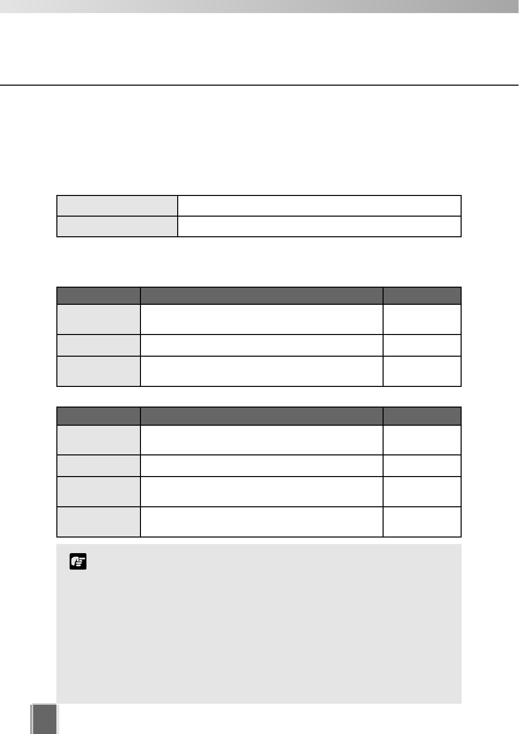
[System Drive] is a drive that contains a folder in which the
Operating System files are stored. For example, if the Operating
System is installed on Drive C, your system drive is C Drive.
You will need to change settings to show the following folder:
[System Drive]:\Documents and Settings\All Users\Application Data
Select ‘Folder Options’ from the ‘Tools’ menu in Windows Explorer.
Click the ‘Show hidden files and folders’ radio button in the ‘View’ tab.
[Storage Server Installed Folder] is (if you installed Storage Server on
your C Drive) as follows:
C:\Program Files\Canon\WebView\NVR
Note
150
Example Operating Conditions
VK-64 File Locations
The following is a list of places where various VK-64 data is saved.
Recorded data and event data
The recorded and event data are saved in the following folders according to your settings
for [Save video in] and [Drive] when you register camera servers.
The following files are saved in their respective folders that reside on the PC on which the
Storage Server or Viewer is installed:
Log files
Recorded data [Drive]:\WebView-NVR\videofiles
Event data [Drive]:\WebView-NVR\eventfiles
Log Path PC location
Storage Server [System Drive]:\Documents and Settings\All Users\
Application Data\Canon\WebView\NVR\logs\
Storage Server
Apache [Storage Server Installed Folder]:\websrvr\logs\ Storage Server
Viewer [System Drive]:\Documents and Settings\All
Users\Application Data\Canon\WebView\NVR\logs\
Viewer
Settings files Path PC location
Storage Server [System Drive]:\Documents and Settings\All
Users\Application Data\Canon\WebView\NVR\conf\
Storage Server
Apache [Storage Server Installed Folder]:\websrvr\conf\ Storage Server
Master Storage
Server [System Drive]:\Documents and Settings\All Users\
Application Data\Canon\WebView\NVR\conf\
Storage Server
Viewer [System Drive]:\Documents and Settings\All Users\
Application Data\Canon\ WebView\NVR\
Viewer
Setting files

Index

Index
152
A
Active region, . . . . . . . . . . . . . . . . . . . .72
Add Camera Server, . . . . . . . . . . . . . .43
Add Storage Server, . . . . . . . . . . . . . . .43
Add Users, . . . . . . . . . . . . . . . . . . . . . .27
Admin Viewer, . . . . . . . . . . . . . . . . . .112
Area Ratio, motion detection, . . . . . . . .74
Audio feature (VB-C50i, VB-C50iR and VB-C50FSi),
. .14
B
Backlight, . . . . . . . . . . . . . . . . . . . . . . .68
In Video Window menu, . . . . . . . . . 110
C
Calendar, . . . . . . . . . . . . . . . . . . . . . .129
Jump to Time, . . . . . . . . . . . . . . . . 129
Searching Events, . . . . . . . . . . . . . 135
Camera, . . . . . . . . . . . . . . . . . . . . . . . .42
Add Camera Server dialog, . . . . . . . 52
Add Camera Server Dialog types, . . 51
Add Storage Server, . . . . . . . . . . . . . 46
Backlight, . . . . . . . . . . . . . . . . . . . . . 68
Camera Angle, . . . . . . . . . . . . . . . . . 77
Camera Control Advanced Settings, 109
Camera Control Panel, . . . . . . . . . . 109
Camera Control Panel, Focus, . . . . 109
Camera Control Panel, Speed, . . . . 109
Camera controls in Video Window, . 108
Camera Selection in the Viewer, . . . 100
Configure Camera Summaries, . . . . 46
Edit Camera Server Settings, . . . . . . 55
Find Camera Servers, . . . . . . . . . . . 49
Preset Angle, . . . . . . . . . . . . . . 56, 109
Remove Camera Server, . . . . . . . . . 58
Set connection details, . . . . . . . . . . . 53
Start Control, pan, tilt, zoom, . . . . . . 56
Update camera position, . . . . . . . . . 56
Camera Control Panel, . . . . . . . . . . . .109
Camera Servers, . . . . . . . . . . . . . . . . .12
Add camera server, . . . . . . . . . . . . . 43
Edit camera server, . . . . . . . . . . . . . 43
Find camera server, . . . . . . . . . . . . . 43
Remove camera server(s), . . . . . . . . 43
Setting up Camera Servers, . . . . . . . 18
Camera Summaries, configure, . . . . . .46
Configuration, . . . . . . . . . . . . . . . . . . .33
About Locations and Zones, . . . . . . . 44
Add a Location and Zone, . . . . . . . . 47
Camera Summary, configure, . . . . . . 46
Configuration & Preferences Screen, 38
Configuration Process, . . . . . . . . . . . 36
Configure Viewer Settings, . . . . . . . . 88
Edit Camera Server Settings, . . . . . . 55
Edit Sensor Event Record Settings, . 76
Find Camera Servers, . . . . . . . . . . . 49
Motion and Sensor Settings, . . . . . . 70
Operator acknowledgement box, . . . 91
Overview of configuration process, . . 36
Pan, Tilt and Zoom, . . . . . . . . . . . . . 56
Recording Schedules, . . . . . . . . . . . 62
Remove Camera Server, . . . . . . . . . 58
Resolution, setting, . . . . . . . . . . . . . . 68
Configuration and Preferences Screen, 38
Accessing, . . . . . . . . . . . . . . . . . . . . 35
Custom Grid, . . . . . . . . . . . . . . . . . . .123
D
Drag, drop and re-size Video Windows, 119
Disk space management . . . . . . . .24, 146
E
Edit Camera Server, . . . . . . . . . . . .43, 57
Edit Storage Server, . . . . . . . . . . . . . . .43
Edit Users, . . . . . . . . . . . . . . . . . . . . . .28
Events, . . . . . . . . . . . . . . . . . . . . . . . .25
Event Indicator, . . . . . . . . . . . . . . . 107
Event pre and post recording, . . . . . 75
Live Events Log, . . . . . . . . . . . . . . 132

153
I
Index
Search Criteria, . . . . . . . . . . . . . . . 135
Searching Events, . . . . . . . . . . . . . 134
Viewing found events, . . . . . . . . . . 136
Extracting video to save, . . . . . . . . . .131
F
Find Camera Server, . . . . . . . . . . . . . .43
Firmware Versions, . . . . . . . . . . . . . . .12
Firmware Upgrade, . . . . . . . . . . . . . 12
Frame rate, . . . . . . . . . . . . . . . . . . . . .78
recording example, . . . . . . . . . . . . . 147
Set for record video, . . . . . . . . . . . . . 78
Frame sizes, . . . . . . . . . . . . . . . . . . .144
G
Get Camera Control, . . . . . . . . . . . . .108
Grids, . . . . . . . . . . . . . . . . . . . . . . . . .119
Alignment Grid, . . . . . . . . . . . . 119, 122
Custom Grid, . . . . . . . . . . . . . . . . . 123
Showing and Hiding, . . . . . . . . . . . 123
Small, Medium and Large Grids, . . 120
H
Hide and show Viewer Task Areas, . . .124
I
Installation Procedures, . . . . . . . . . . . .19
Serial Number, . . . . . . . . . . . . . . . . . 20
Upgrading from an earlier version, . . 20
Introduction, . . . . . . . . . . . . . . . . . . . . . .2
J
Jump to time, . . . . . . . . . . . . . . . . . . .129
K
keyword event search, . . . . . . . . . . . .135
L
Launching the Viewer, . . . . . . . . . . . . .96
Layout Sequences, . . . . . . . . . . . . . . .118
Layouts, . . . . . . . . . . . . . . . . . . . . . . .114
About the Layout menu, . . . . . . . . . 114
Layout Grids, . . . . . . . . . . . . . . . . . 119
Layout Sequences, . . . . . . . . . . . . . 118
Organizing Layouts/Layout Sequence, 115
Saving a Layout/Layout Sequence, . 117
Shared and Personal Layouts, . . . . 114
Live Events Log, . . . . . . . . . . . . . . . .132
Locations and Zones, . . . . . . . . . . . . . .44
Add Locations and Zones, . . . . . . . . 47
Search events by, . . . . . . . . . . . . . . 135
Viewer, select Locations and Zones, 101
Login dialog, . . . . . . . . . . . . . . . . . . . .30
Low disk space threshold, . . . . . . . . . .23
M
Manual recording, . . . . . . . . . . . . . . . .111
Master Storage Server, . . . . . . . . . . . .18
Maximum Disk Space Used, . . . . . . . . .23
Maximum Retained History, . . . . . . . . .23
Motion and Sensor settings, . . . . . . . . .70
Motion Detection, . . . . . . . . . . . . . . . . .71
Detection Indicator Colors, . . . . . . . . 73
Motion Detection Options, . . . . . . . . 73
Motion Detection on camera servers, . .75
Multiple Storage Servers and Viewers, .17
N
Night Mode, . . . . . . . . . . . . . . . . . . . . .76
O
Operating Environment, . . . . . . . . . . . .13
Overview, . . . . . . . . . . . . . . . . . . . . . . . .7
Overview of Setup, . . . . . . . . . . . . . . . .10
P
Pan, Tilt, Zoom; Schedule Item dialog, .68

154
Index
Pan, Tilt, Zoom; Sensor Event dialog, . .77
Pan, Tilt, Zoom from Video Window, . .108
Preset camera position, . . . . . . . . . . . .68
Proxy address, setting the, . . . . . . . . . .23
proxy server, about settings, . . . . . . . 32
R
Record Now, . . . . . . . . . . . . . . . . . . . .111
Recording Schedules, . . . . . . . . . . . . . 62
Add/Delete a Day, . . . . . . . . . . . 84, 85
Add/Delete a Schedule Type, . . . . . . 82
Add/Edit Schedule Item dialog, . . . . . 66
area for detection, . . . . . . . . . . . . . . 71
Edit and Delete, . . . . . . . . . . . . . . . . 64
Edit Motion and Sensor settings, . 70-78
Normal Schedule, . . . . . . . . . . . . . . 62
pre and post event settings, . . . . . . . 75
Remove Camera Server, . . . . . . . . . . .43
Resolution, . . . . . . . . . . . . . . . . . . . . . .68
S
Schedules, . . . . . . . . . . . . . . . . . . . . . .62
About Special Day Recording, . . . . . 80
Add or modify a schedule, . . . . . . . . 64
Add Schedule, multiple cameras, . . . 64
Delete a Day, . . . . . . . . . . . . . . . . . . 85
Delete a Schedule Type, . . . . . . . . . 83
Motion Detection Settings dialog, . . . 71
Recording Schedule dialog, . . . . . . . 64
Select multiple items and drag, . . . . . 63
Set backlight compensation, . . . . . . . 68
Set motion or sensor recording, . . . . 67
Set night mode (VB-C50i/VB-C50iR/VB-C50FSi)
,
. . 68
Set preset angle, . . . . . . . . . . . . . . . 68
Set recording frames per second, . . . 67
Set the recording period, . . . . . . . . . 66
Searching Events, . . . . . . . . . . . . . . .134
Event Search button, . . . . . . . . . . . 134
View Event in Camera, . . . . . . . . . . 136
Sensitivity, motion detection, . . . . . . . .74
Setting disk drive, . . . . . . . . . . . . . . . .23
Setting recorded video, . . . . . . . . . . . .23
Setting the Master Storage Server, . . . .31
Setting up Event Notifications, . . . . . . .25
Setting up the Camera Servers, . . . . . .18
Setting up Users, . . . . . . . . . . . . . . . . .26
Setup camera position, . . . . . . . . . . . .56
Shade Correction, . . . . . . . . . . . . . . .112
Special Day Recording, . . . . . . . . . . . .80
Starting VK-64 Viewer, . . . . . . . . . .30, 96
Storage Server
Add Storage Server dialog, . . . . . . . . 46
Bandwidth and disk space, . . . . . . . 145
Changing the Storage Server, . . . . . . 31
Configure the Storage Server, . . . . . 22
Disk drive settings, . . . . . . . . . . . . . . 23
Disk space management . . . . . . 24, 146
edit, Camera Summary, . . . . . . . . . . 46
Frame sizes, . . . . . . . . . . . . . . . . . 144
Launching Procedure . . . . . . . . . . . . 22
Low disk space threshold, . . . . . . . . 23
Managing disk space, . . . . . . . . 24, 146
Multiple use of, . . . . . . . . . . . . . . . . . 18
Proxy server, enable, . . . . . . . . . . . . 23
Setting Events/Event Notifications, . . 25
Setting maximum disk space, . . . . . . 23
Setting maximum file size/duration, . 23
Setting maximum history, . . . . . . . . . 23
Start or Stop the Storage Server, . . . 23
Storage Server Performance, . . . . . 148
Storage Server system requirements, 13
Supported Camera Servers, . . . . . . . . .12
System Configuration, . . . . . . . . . . . . . .8
System Requirements, . . . . . . . . . . . . .13
T
Timeline, . . . . . . . . . . . . . . . . . . . . . .126
Daylight Savings Indicator, . . . . . . . 130
Event Display Area, . . . . . . . . . . . . 128
Jump to Time, . . . . . . . . . . . . . . . . 129

155
Index
I
Index
Overview, . . . . . . . . . . . . . . . . . . . . 126
Playback Controls, . . . . . . . . . . . . . 128
Playhead, . . . . . . . . . . . . . . . . 126, 128
Recorded video, . . . . . . . . . . . . . . . 128
View and search events, . . . . . . . . 132
Troubleshooting, . . . . . . . . . . . . . . . .138
U
User Management, . . . . . . . . . . . . . . .26
Users, adding and editing Users, . . . . .26
Login to Viewer, . . . . . . . . . . . . . . . . 97
Removing users, . . . . . . . . . . . . . . . 28
V
VB, firmware, . . . . . . . . . . . . . . . . . . . .12
Video Windows, . . . . . . . . . . . . . . . . .102
Admin Viewer, . . . . . . . . . . . . . . . . 112
Capture Still Frame, . . . . . . . . . . . . 111
Close Window menu item, . . . . . . . 112
Control External Devices, . . . . . . . . 111
Creating, scaling and moving, . . . . 102
Enable Backlight Compensation, . . 110
Event Indicator, . . . . . . . . . . . . . . . 107
Night mode . . . . . . . . . . . . . . . . . . . 111
Other Menu Options, . . . . . . . . . . . 111
Pre-recorded Video Indicator, . . . . . 107
Re-size when placed . . . . . . . . . . . . 119
Select Preset, . . . . . . . . . . . . . . . . 109
Selecting Multiple Video Windows, . 105
Shade Correction, . . . . . . . . . . . . . 112
Video Display Size, . . . . . . . . . . . . . 110
Video Window States, . . . . . . . . . . 106
Viewer, . . . . . . . . . . . . . . . . . . . . . . . . .34
Alert duration, . . . . . . . . . . . . . . . . . 88
Camera Thumbnails, . . . . . . . . . . . 100
Change Storage Server, . . . . . . . . . . 64
Configure Viewer Settings, . . . . . . . . 88
Example Viewer Screen, . . . . . . . . . 94
Launching Procedure, . . . . . . . . . . . 30
Login, . . . . . . . . . . . . . . . . . . . . . . . 97
Operator acknowledgement, . . . . . . . 91
Select Location and Zone, . . . . . . . 101
Selecting Cameras for Viewing, . . . 100
Show/hide task areas, . . . . . . . . . . 124
Starting the Viewing Screen, . . . . . . . 96
Viewer Settings window, . . . . . . . . . . 88
Viewer Settings, Edit Events, . . . . . . 91
Viewer Settings, Event Priority, . . . . . 88
Viewer Login, . . . . . . . . . . . . . . . . . . . .97
Viewing Screen, . . . . . . . . . . . . . . . . . .94
Camera Selection Area, . . . . . . . . . 100
Camera thumbnail, . . . . . . . . . . . . . 102
Create/scale/move Video Windows, 102
Customize layouts into grids, . . . . . 119
Launch the Viewer, . . . . . . . . . . . . . . 96
Location and Zone menus, . . . . . . . 100
Menu Bar, . . . . . . . . . . . . . . . . . . . . 98
Using the Layout menu, . . . . . . . . . 114
Using the Timeline, . . . . . . . . . . . . . 126
Z
Zones and Locations, . . . . . . . . . . . . . .44
Zoom, . . . . . . . . . . . . . . . . . . . . . . . .108
509-0162 CANONsama NETWORK VIDEO RECORDER VK-64/VK-16 USER’S MANUAL hyo1-4
Network Video Recorder
VK-64/VK-16 v1.1 User
’s Manual
User’s Manual
Ver. 1.1
Network Camera Recording and Monitoring System
Network Video Recorder
VK-64/ VK-16 v1.1
Storage Server & Viewer
CANON INC. 30-2, Shimomaruko 3-chome, Ohta-ku, Tokyo 146-8501, Japan
U.S.A. CANON U.S.A.,INC. NEW JERSEY OFFICE
100 Jamesburg Road, Jamesburg, NJ 08831 USA
CANON U.S.A.,INC. CHICAGO OFFICE
100 Park Blvd., Itasca, IL 60143 USA
CANON U.S.A.,INC. LOS ANGELES OFFICE
15955 Alton Parkway, Irvine, CA 92618 USA
CANON U.S.A.,INC. HONOLULU OFFICE
210 Ward Avenue, Suite 200 Honolulu, HI 96814 USA
zIf you have any questions, call the Canon U.S.A. Information
Center toll-free at 1-800-828-4040(U.S.A.only)
CANADA CANON CANADA INC.NATIONAL HEADQUARTERS
6390 Dixie Road, Mississauga, Ontario L5T 1P7
CANON CANADA INC. CALGARY
2828, 16th Street, N.E, Calgary, Alberta T2E 7K7
CANON CANADA INC. MONTRÉAL
5990 Côte-de-Liesse, Montréal, Québec H4T 1V7
zIf you have any questions, call the CANON CANADA Customer Information
Centre toll-free at 1-800-OK-CANON (652-2666) (Canada only)
MEXICO CANON MEXICANA, S DE R.L.DE C.V.
Boulevard Manuel Avila Camacho, No.138 PB, Pisos 15, 16 y 17 Col Lomas de
Chapultepec C.P. 11000 México, D.F. México
CENTRO Y
SURAMERICA CANON LATIN AMERICA, INC.
703 Waterford Way, Suite 400, Miami, FL33126, USA
ASIA CANON SINGAPORE PTE LTD
1 HarbourFront Avenue, #04-01, Keppel Bay Tower
Singapore 098632
CANON HONGKONG CO., LTD.
19/F., The Metropolis Tower, 10 Metropolis Drive, Hunghom, Kowloon,
Hong Kong
OCEANIA CANON AUSTRALIA PTY. LTD.
1 Thomas Holt Drive, North Ryde, Sydney, N.S.W. 2113, Australia
EUROPE CANON EUROPA N.V.
Bovenkerkerweg 59-61, P.O. Box 2262, 1180 EG Amstelveen, The Netherlands
CANON EUROPE LTD.
6 Roundwood Avenue, Stockley Park, Uxbridge Middlesex, UB11 1JA,
United Kingdom
PUB. VK-050902 © CANON INC.2005 PRINTED IN JAPAN
