Canon 6401 B Field Unit Software User Manual To The 3203bbcb A9f6 4fb0 A186 E879e4813aa7
User Manual: Canon 6401 B to the manual
Open the PDF directly: View PDF ![]() .
.
Page Count: 47
- Field Test Unit Software
- Table of Contents
- 1.INTRODUCTION
- 2.GETTING STARTED
- 3.(UN)LOAD,PLOT ©
- 4.PLOTX -EXTENSIONS
- 5.DATA STORAGE FORMAT
- 6.NFTU COMMANDS
- 7.FTUC COMMANDS

STARLOG
Field Test Unit
Software
Model 6401 B
(Canon X-07)
User Manual Supplement
6202 Revision F
January 5, 1989
Copyright Notice
Copyright
©
Unidata Australia 1988.
All
rights reserved. No part of this
publication may be reproduced, transmitted, transcribed, stored in a
retrieval system, or translated into any language or computer language, in
any form or by any means, electronic, mechanical, magnetic,
optical,
chemi-
cal, manual or otherwise, without prior written permission of Unidata
Australia, 3 Whyalla Street, Willetton, Western Australia, 6155, Australia.
Published by Lynn MacLaren Publishing
IBM®
is a registered trademark of International Business Machine Corp.

Field Test Unit Software
Table of
Contents
1.
INTRODUCTION
1.1 PORTABLE DATA LOGGER
1.1
.1
Memory structure . . . . . . . .
1.2 FIELD TEST UNIT . . . . .
1.2.1
Why use a FTU?
. . . . . . . . .
1.2.2 Installation. . . . . . . . . . . . . .
1.2.3 Switching on the
FTU
. . . . .
1.2.4 Running a Program . . . . . .
1.3 CASSETTE STORAGE
. .
1
.............
1
.......................
1
..............
2
.......................
2
.......................
2
.......................
3
.......................
3
..............
3
3
1.3.1 Attaching the cassette
...........................
1.3.2 Saving a Program
...............................
4
1.3.3 Loading a Program
.............................
4
2.
GETTING
STARTED
5
2.1 PROGRAMS
......................
5
2.1.1 Filename Extensions
............................
5
2.2 FTU MEMORY GUIDE
.................
5
2.3
FTU
INITIALIZATION
.................
6
2.4 LOADING “PLOT” IN 16K RAM FTU
..........
7
3. (UN)LOAD, PLOT & COPY
8
3.1 STANDARD FEATURES
................
8
3.2 COMMAND FILES
..................
9
3.3
COPY(ING)
FILES
...................
9
3.3.1
Running COPY
.................................
9
3.3.2 COPY -
Operator Responses
....................
10
3.3.3 Timing considerations
..........................
10
Contents
i

3.4
(UN)LOADlNG TO CASSETTE/RAM
........
10
3.4.1 Running
LOAD
.............................
.11
3.5 PRlNTlNG
&
PLOTTING RECORDINGS
......
11
3.51 Running PLOT
................................ .
11
3.6
LOAD/PLOT - OPERATOR RESPONSES
...... 11
3.7 PRINT/PLOT/LOAD/COPY - Examples
.......
15
3.7.1 PRINT-Example
..............................
.15
3.7.2
PLOT
-
Example
...............................
17
3.7.3LOAD-Example
..............................
.18
3.7.4 COPY-Example.. ............................
.21
4.
PLOTX
-
EXTENSIONS
22
4.1 RUNNING PLOTX ..................
22
4.1.1 PLOTX-Operator Responses
.................
.22
5. DATA STORAGE FORMAT
25
5.1
FTU
FILE FORMAT
.................
25
5.1.1 HEADER Message Format
......................
.25
5.1.2 DATA Message Format
..........................
26
5.1.3 END Message Format . .
........................
.26
5.2 HOST COMPUTER PROGRAM TO RECEIVE DATA 2 6
6. NFTU COMMANDS
28
6.1 OPERATION . .
...................
28
6.1.1 L COMMAND
.................................
.28
6.1.2 B COMMAND
................................
.28
6.1.3 P COMMAND
................................
.29
6.1.4 CURSOR KEY COMMANDS
.....................
.29
6.1.5 'space' COMMAND ..........................
.29
6.2 INITIALIZATION
...................
29
6.3 CHANNEL ADDRESSES
..............
30
6.4
“NFTU.X07”
-
PROGRAM LISTING
. . . . . . . . . 30
7.
FTUC
COMMANDS
32
ii Contents

Field
Test Unit Software
7.1 DISPLAY
FORMAT
.................
.32
7.2
DISPLAY OF THE LOGGERS CURRENT
MEMORY
VALUES
........................
.32
7.3 USER DEFINED SCREEN FORMAT
........
.33
7.4 MEMORY ADDRESSING
..............
.34
7.5 CURSOR KEYPAD
.................
.34
7.6 SCREEN FORMAT FILES
..............
.35
7.7
COMMANDS TO MODIFY DATA
LOGGER
.....
.35
7.7.1
“P”
-Put .....................................
35
7.7.2 “T” - TIME
....................................
36
7.7.3
“d”
-
DISPLAY
* ................................
36
7.7.4 “r” - RESET * . .................................
37
7.7.5
“j”
& “a”
-
JUMP TO LOG & ADDRESS toggle *
......
37
7.7.6 “D”
-
DATA.
...................................
37
7.7.7
“J”
-JUMP to ADDRESS
........................
37
7.8 X-07 DIRECT COMMANDS FROM FTU-PROM
...
.37
7.8.1 “t” - TIME
.....................................
37
7.8.2
“F”
-
FREE
....................................
38
7.8.3
“Q”
-
QUIT
.....................................
38
7.8.4 “b” - BAUD . . ..................................
38
7.8.5
“s”
-
S300
................................
38
7.8.6 “x” - TRANSFER
...............................
38
7.9 INDIRECT & MISCELLANEOUS COMMANDS 39
7.9.1
“@”
-INDIRECT JUMP
..........................
39
7.10 SUMMARY OF COMMANDS
............
.40
Contents
iii

Field Test Unit Software
Contents

Field Test Unit Software
1. INTRODUCTION
The purpose of this documentation is to describe the function and opera-
tion of the Model
6401B
Field Test Unit in conjunction with
UNIDATA’s
Portable Data Logger. This document is aimed at the inexperienced user
who is unfamiliar with the Field Test Unit
(FTU).
The Portable Data
Logger
and Field Test Unit act as a team for the collec-
tion and transfer of data from
remote,
unmanned locations. The data logger
is a battery operated data gathering unit, and the Field Test Unit is a port-
able dedicated computer with specialized software for communication with
the data logger.
1.1 PORTABLE DATA LOGGER
The Portable Data Logger (PDL) is a microprocessor based device
designed to have a battery lifetime of over 2 years. This allows the logger to
remain in the fields for long periods of time for the recording of data. The
data is recorded in CMOS
RAM
memory which is available in 8K to 64K
capacities. The logger provides analogue and digital inputs for data sam-
pling, and internal logger programs and crystal clock for the recording of
data in the logger’s memory.
1.1.1 Memory structure
The memory of the logger is divided into 256 byte Blocks (e.g. a 24K logger
will have 96 blocks, and a 64k logger has 256 blocks). Hence, any particular
location in the logger’s memory can be referred to in two ways: either by its
absolute location in memory, or by its block and location within that block
(e.g. absolute location 0 is also block
0
location 0; absolute location 1023 is
block 3 location 255).
Block 0 is
used
to store the clock, pointers, counters, ac-
cumulators, channels and other information neces-
sary to the running of the logger.
Block 1 is used to store Buffer Pointer information (BLK 1, LOC
0) and the Data Logger program (BLK 1, LOC 128)
Blocks 2 & 3 are reserved for the Data Logger Program.
Section 1. INTRODUCTION 1

Field Test Unit Software
Blocks 4 onwards (location 1024 to the end of memory) are
reserved for logger data storage. Bytes are logged
sequentially, without gaps, and the number of bytes
logged per log interval will depend on the PDL
program.
1.2 FIELD TEST UNIT
The Field Test Unit (FTU) is a battery powered, Intel 8085 based
microcomputer with resident Microsoft BASIC
(20K
ROM). Memory
capacities of 8K or 16K RAM are available for program and data storage.
RAM memory is divided between a text area and a file area. The text area
is used for loading and executing BASIC programs. The file area is used to
store Program and Data
files.
Files in the file area are called RAM files.
Both the text area and the file area are retained when the FTU is switched
off, but these areas will be cleared if the batteries are removed.
1.2.1 Why use a FTU?
The Field Test Unit allows the programming
and
interrogation of the data
loggers in the field. The FTU can be used to
:
•
Display and alter channels, accumulators, and memory
locations in the data logger.
• Unload the logger into a RAM
fiIe
or onto cassette.
•
Load the logger with new programs from a
RAM
file or
from cassette.
•
Transfer logger data and programs between the
FTU,
cassette, and a host computer.
1.2.2 Installation
The
FTU
should come with the following:
•
X-07 (the
FTU)
•
CANNON X-07 User’s Guide
•
BASIC Reference Manual
•
Progr
amming
Guide for Beginners
•
Reference Card (for X-07)
2 Section 1. INTRODUCTION

Field Test
Unit Software
•
Batteries (AA x 4)
•
Model 6602E cable to connect FTU to Data Logger
•
Model 6401D Mains Power Pack
•
Prom with
STARLOG
Software (already installed)
•
Reference Card for (FTU)
1
.2.3
Switching on the
FTU
Ensure that the batteries have been inserted and that the Lock Switch (slide
switch, underneath) is in the ON position, then press the ON/BREAK key.
The FTU should power on and the following appear on the screen :
Copyright(c) 1983 by
Microsoft & Canon
14940 Bytes free
Note, however, that the number of Bytes free may differ from the above as
it depends on the size of the file area that has been set (the size of the file
area can be changed)
1.2.4 Running a Program
To run a program, use the BASIC command :
RUN"filnam"
where filnam is the name of the file you wish to run.
1.3 CASSETTE STORAGE
Cassettes may be used for long term storage of Programs and data. It is ad-
visable to keep a copy of programs on cassette, as the contents of the file
area may sometimes be destroyed.
1.3.1
Attaching the cassette
The cassette cable plugs into the small round DIN-type socket on the right
hand side of the
FTU.
The other end of the cable has three
pIugs.
These
should be plugged into the cassette recorder as follows:
RED MIC (Input)
Section 1.
INTR
ODUCTION
3

GREY EAR (Output)
BLACK
REM (remote
control)
1.3.2 Saving a Program
To save a program on cassette, rewind the cassette to a blank section, then
put the cassette recorder into RECORD.
To save a program that is in the file area type :
CSAVE“filnam”
Where filnam is the file name you wish the program to be saved under. It is
usually good practice to save the program twice (on the same cassette), as a
protection against corruption on the tape.
To save a program that is in the file area, first load it into the text area by
using the LOAD command :
LOAD“filnam”
then save it on cassette as above.
1.3.3 Loading a Program
To load a program from cassette, rewind the cassette to the start of the
file,
then put the cassette recorder into PLAY, then type:
CLOAD“filnam”
Where
filnam
is the file name of the program you wish to load. If the
file
name is left out, then the next program on the tape will be loaded.
To save the program in the file area use the command :
SAVE“filnam”
4Section 1. INTRODUCTION

Field Test Unit Software
2. GETTING STARTED
The
STARLOG
FTU
Software Package Model 6302A consists of a cassette
tape, a memory chip
(6264LP)
and this manual.
2.1 PROGRAMS
The Field Test Unit
(FTU)
(Canon X-07) is usually delivered complete with
the
“FTU”
prom loaded and ready to use.
The following programs are not loaded into the RAM file but are stored on
the cassette tape which is included as part of the
STARLOG
FTU
Software
Package:-
FTUC
Provides interrogation and testing of the Data Logger in
the field.
LOAD Lead programs into the Data Logger, Unload recorded
information from the Data Logger.
COPY Transfer Data Logger information between FI’U RAM,
cassette tape or RS-232 host computer.
PLOT
Print or Plot Data Logger recorded information.
PLOTX
As above plus extended features such as plot averaging,
maxima, minima and total calculations.
2.1.1
Filename Extensions
Files saved in the FTU RAM
sions:-
directory will have the following file
exten-
“D” means a Data File or Logger Program
“P” means a Program FiIe written in BASIC
“F” means a Command File
2.2
FTU
MEMORY GUIDE
The Field Test Unit comes complete with a 16k RAM which is sufficient to
operate all UNIDATA supplied software. The FTU RAM may be ex-
panded to 24k with an 8k memory card.
Section 2. GETTING STARTED 5

Field Test Unit Software
To use the 8k
6264LP
RAM supplied to increase the
FTU
memory to
16k
switch the
FTU
off and remove the cover of the chip socket on the back of
the FTU.
Replace the
FTU
ROM with the
RAM
chip and change the memory select
switch from ROM to RAM. Replace the cover press the reset button on the
back of the
FTU
and switch on.
R A M Programs in RAM Command
Files
Log Programs Data
16K
PLOT RAM/Cassette RAM/Cassette Cassette
(in text area)
16K
LOAD/COPY/FTUC RAM/Cassette RAM/Cassette Cassette
(in RAM file)
24K
PLOT/COPY/FTUC RAM/Cassette RAM/Cassette Cassette
2.3
FTU
INITIALIZATION
If for any reason the
FTU
programs need to be loaded, the following proce-
dure should be
used:-
1.
2.
3.
4.
5.
6.
7.
Using a pencil, press the RESET button at the rear of the
FTU. (This is a Master Reset, so ALL PROGRAMS WILL
BE LOST).
Connect FTU to Cassette Recorder with Model 6302A
software cassette tape inserted/rewound and ready to use.
Press ON/BREAK key on the
FTU.
The message “14940
Bytes free” will appear. (Note: at least 14940 Bytes are re-
quired to operate this software, more ‘free’ bytes are fme).
Type:- FSET
10000
Return
(2300
if using PLOT/PLOTX)
Type:-
CLOAD
“FTUC” Return (system should respond with
‘Found FTUC’ and then continue to read the program
FTUC
from the cassette tape and store it in the
FTU)
Type:-
SAVE
“FTUC” Return (to save the program FTUC
permanently in the
FTU’s
RAM file area.) SAVE
“LOAD/UNLOAD”
Repeat Steps 5 & 6 above to Load
&
Save programs
“LOAD” and “COPY”. Program “PLOT” may also be loaded
if there is sufficient RAM in the
FTU
[in this case, “PLOT”
should be LOAD(ed) and SAVE(ed) first, then “FTUC”,
“LOAD” and “COPY”).
6
Section 2. GETTING STARTED

Field Test Unit Software
Note:- all programs on the cassette are stored twice. This means
the
message “SKIP : FTUC” might appear on the screen first before
the
next file is loaded
8. Type:- NEW then press Return
All FTU programs are now loaded and ready to use.
9. Type:- RUN “FTUC” then press Return
(To begin FTUC operating. Press BREAK key then RUN
“LOAD” or RUN “COPY” to begin those programs)
2.4
LOADING “PLOT’ IN 16K
RAM
FTU
The Model
6302A
Software
Support (Version
V#5.0
or later) requires a
16k
memory FTU (Canon X-07), therefore only the Print/Plot Package can
be loaded into the FTU If the
FTU
has been expanded to
24k,
then other
FTU
utilities may also be loaded and the Print/Plot Package may be saved
as a RAM file in the FTU.
To load program “PLOT” (the Print/Plot Package):-
1.
DELETE all
RAM
files in the FTU (or perform Step 1.
above).
2.
Connect cassette player (Step 2. above) and insert tape, side
B.
3.
Type:- FSET 2300 then press Return
4.
Type:- CLOAD “PLOT” then press Return
(The system should respond with ‘Found:PLOT’ and con-
tinue to load the program into the FTU)
Note:- don’t save “PLOT” in the RAM file area (in a
16k
FTU).
5. Type:- RUN then press Return
(To begin execution of the Print/Plot package).
Section 2.
GETTING
STARTED 7

Field Test Unit Software
3. (UN)LOAD, PLOT & COPY
The Model
6302A
Software Support Package (Version
V#5.0
or later)
(Un)load/Plot/Copy allows information to be unloaded from a Data Logger
and printed or plotted on a printer/plotter (Canon X-710) attached to the
Field Test Unit (Canon X-07). In print mode, any standard
80
column
printer may be used when interfaced to the
FTU
via the ‘Centronics’ printer
interface or RS-232 communications interface.
In addition, program and data
files
may be transferred between cassette,
RAM, Data Logger and a host computer in various formats.
3.1
STANDARD FEATURES
The (Un)load/Plot/Copy package will:-
a)
b)
c)
d)
e)
f)
unload a Data Logger and store the resulting data in a RAM file
(requires 24k) or a cassette file on a datacassette tape.
load a logger program from a RAM file or a cassette file into a
Data Logger.
print the contents of an unloaded Data Logger direct or from a
RAM file or a cassette file in a tabular (column) format (up to
8 channels/fields per print) onto a Canon X-710 printer/plotter,
a Centronics interfaced 80 column printer or a RS-232 inter-
faced 80 column printer.
plot the contents of a Data Logger direct or from a RAM
file
or a
cassette file
in
a four color multi-plot format (up to 8 chan-
nels/fields per plot) onto a Canon X-710 printer/plotter.
transfer unloaded information or logger programs between a host
computer and the
FTU
in ASCII format via an RS-232 com-
munication channel.(see Appendix A for message format).
transfer unloaded information or logger programs between an
IBM-PC type system and the
FTU
in LOGGER message for-
mat. (using the IBM-PC utility program “PDLIO”). Print or
plot logger files direct from an IBM-PC type system (using the
PDLIO utility program).
NOTE: The IBM-PC utility program PDLIO is not part of the
(Un)load/Plot/Copy
Software Package. Program PDLIO is included
within the
STARLOG
Software Support Package for the IBM-PC (and
8
Section 3. (UN)LOAD, PLOT& COPY

Field
Test
Unit
Software
compatibles). If you require to use PDLIO you must purchase that
package separately.
g) copy data files and command files between cassette, RAM and the
RS-232 communication channel (host computer).
h)
save frequently used (Un)load/Plot operator responses into com-
mand files in RAM or on cassette.
3.2 COMMAND
FILES
Once the format of the (un)load or print/plot output has been decided, the
operator commands (entered into the keyboard in response to the questions
listed below) may be saved in a RAM file or on cassette.
This feature saves the operator entering
all
the responses every time a plot
or unload is performed. Instead, the operator simply enters in the command
file name and the (un)load or print/plot proceeds automatically using the
pre-saved operator commands from that command file.
Many command files may be created and saved, allowing command files for
a variety of loading, unloading, printing or plotting operations.
3.3 COPY(ING) FILES
The “COPY” program allows data files or command files to be transferred
to/from RAM/cassette or to/from FTU and a host computer. These
files
must be standard BASIC files in ASCII format (lines terminated with a car-
riage return and
less
than
255
characters in length).
3.3.1 Running COPY
1.
Connect datacassette and/or RS-232 link to FTU
2.
Type:- RUN “COPY” then press Return
3. Answer the following questions:
Section 3. (UN)LOAD, PLOT & COPY
9

Field Test Unit Software
3.3.2
COPY - Operator Responses
Question
Cassette or Ram file
INPUT file or Xfr
(RS-232)?
Answer
C
= Cassette
file
R =
RAM
file
X =
RS-232
communication channel to a
host
computer.
Enter
Input file
Name of Input file,extension
name, type
(default ,D)
The above two questions are repeated for the OUTPUT file.
Baud Rate? You have
selected
Xfr
mode. Maximum
Baud
rate is
8000.
(use 8000/4800/2400/
1200/300)
Note: if cassette selected Baud
Rate is not asked
for.
3.3.3
Timing considerations
When copying a file from a host computer (via the RS-232 communications
channel)
to a
RAM file in the FTU,
a
delay of two (2) seconds must be
provided by
the
host computer after sending each line before
the next line
of the fiIe is sent to the
FTU.
This delay must be increased to thirty (30)
seconds per line when the
FTU
is storing
the file
on a data cassette.
NOTE: The transfer to/from a host computer is terminated by the last line
containing the termination word END followed by a carriage return.
(i.e.“END” then press Return)
3.4
(UN)LOADING TO CASSETTE/RAM
Either program “PLOT” or program “LOAD” may be used to unload data
from a Data Logger.
“PLOT” contains all the features of “LOAD” but “PLOT” (un)loading is
slower and requires a larger amount of RAM (memory).
10
Section 3. (UN)LOAD, PLOT& COPY

Field Test Unit Software
3.4.1 Running LOAD
1.
Connect Data Logger to FTU. (connect datacassette)
2.
Type:- RUN “LOAD” then press Return (or RUN “PLOT”)
3.
Answer the relevant questions described below
3.5
PRINTING
&
PLOTTING RECORDINGS
The program “PLOT” is used to print or plot the recorded information from
the Data Logger. This information may be from stored files in RAM or on
cassette or alternatively, “PLOT” will print/plot directly from a Data Logger
connected to the FTU.
3.5.1 Running PLOT
1.
Connect datacassette or Data Logger to FTU
2. Connect & RESET printer Or plotter to FTU
3.
Type:- RUN then press Return (or RUN “PLOT”)
4.
Answer the relevant questions described below
3.6 LOAD/PLOT - OPERATOR RESPONSES
Question
input from Keyboard
input from File; or
Create Command
file?
Answers
K = Keyboard entry of commands
F = Commands are to be read from a
previously created command file
C = Store entered commands in a
command
file
for future use
Enter the way you wish commands to be entered to the program
Note:- if
“C”
is selected, the program creates a command fife only. It
does
not perform any LOAD/COPY/PLOT function.
.
. .
Cassette or Ram file
C = Cassette storage
COMMAND file?
R = Ram storage
Enter the storage device of the command file
Section 3. (UN)LOAD, PLOT& COPY 11
Field Test
Unit
Software
Enter COMMAND
Name of command file,extension (,F is
file name,type default extension)
Enter
the name you
of the command file you wish to create or use
. ____
PLot, PRint, Load or
PL = Plot data logger information
Unload
PR = Print data logger information
L =
Load file
into the logger
U = Unload data logger into file
Enter the function you wish PLOT to perform. Either PL to PLOT data, PR
to PRINT data, L to LOAD data from storage device to a logger or U to
UNLOAD data from a logger to storage device
Cassette or Ram file
C = Cassette storage
INPUT file, or input
R = Ram storage
from Logger?
L = Direct from logger
Enter the storage device that data is to be printed/plotted from
Cassette or Ram file
C = Cassette storage
INP
UT
file
R = RAM storage
Enter the storage device data is to be loaded from
Cassette or
Ram file C = Cassette storage
OUTPUT
file?
R = RAM storage
(24K
F.T.U. only)
Enter the storage device data is to be unloaded to
Enter Output file
Name of data file,extension (,D is default
name,type
extension)
Enter the name you wish give your stored data. This name will be used for
subsequent reference to that data
use buffer 7 time?
if your logger uses buffer 7 to store the
start time, then stored times are used.
Y = YES (use stored times)
N = NO (enter start time on keyboard)
If the program in the logger has been created by the
STARLOG
IBM
software package buffer 7 will contain the time of the first data log. This time
can be used instead of having to enter a start time manually
12
Section
3. (UN)LOAD, PLOT& COPY
Field Test Unit Software
Unload Format,
Pointers & buffer,
Buffer or Done
?
F = FORMAT (set of
Block,Location,Count)
P = Unload a buffer & all buffer pointers
(B1,L0,C128)
B = Unload a buffer (no pointers) (you
enter the B,L,C yourself)
D = DONE (proceed to
(un)load)
Enter the format of the data you wish to operate on
F means that the data you wish to use is to be a contiguous block of logger
memory.
B means the data is contained in one of the loggers 7 buffers.
P
is the same as B except the data is to be used for future use and the buff-
er pointers are also to be saved.
---
. .
. .
Buffer number (0-7)
number of buffer to unload
Enter the buffer number (0
to
7)
of the data you wish to operate on. Buffer
0 is normally used
---
.
B,L,C?
Block,Location,Count
of the data to
unload from the data logger
Enter the block and location (start) of the data and the number of bytes
(count) of data you wish to operate on
Unload Time
Enter Date
&
Time
HHMM DDMMYY
?
Time that logger stored first log HHMM
DDMMYY entry (HHMMSS
DDMMYY) SS
-
optional 1300
121086
HH = hours MM = minutes (SS = seconds
optional) DD = day MM = month
YY=year
An initial time is required in order to time reference all logged data. The
time entered is used along with the log interval to be calculated when each
log was made
.
. . . . . . . .
.
.
Enter Input file
Filename,extension (,D is default
name, type
extension)
Enter the name of the stored data you wish to use. This name must be the
same as the one used when the data was first stored
plot Format, Pointers
& buffer or Done?
F = Formatted input. (set of B,L,C)
P = Buffer & Pointer format
D = Done (ready to Plot)
Section 3. (UN)LOAD, PLOT& COPY
13

Field Test Unit Software
print Format,
Pointers
&
buffer
Bypass,
Skip buffer
or Done?
F = Formatted input. (set of B,L,C)
P = Buffer & Pointer format
B = Bypass data unloaded using
“F”
or
“B”
S = " " " " “P”
D = Done (ready to Print)
Log
interval
(min)?
log interval of logger program in minutes
Enter the log period (the time between data recordings) of the logger
program
Bytes per log? number
of bytes logged at each log interval
(max)
Enter the number of bytes recorded each log by the logger
Fields per log?
number of fields from each log that are to
be Plot/Printed. (Separate channels)
Enter the number of fields of the log you wish to print/plot
Enter Scale Size (cm
Horizontal (X axis or time) scale (the
per hour)?
graph is plotted on its side)
Enter the scale of the time axis. This will determine how much paper the
graph will use
Field
[]
Description of each field to be
bytes,from,to,units,
Print/Plotted.
(location,start,end)
bytes = size of field in bytes and optional conversion formula
specifications (or any combination of size plus for-
mula).
RED = Red thermistor correction
from,to
=
are the scales to be used for the range (Y axis up the
graph)
or the scale
printed.
units = (optional) part of the title for the column/field.
location = (optional) byte position in the log entry where the
field begins. If not specified then the
next
byte in
the log entry is assumed to be the start of this field.
(location is counted from
0,
byte 0 being the
lst
byte location in the log entry).
start,end
= (
o
ptional) prescale values which set the limits of
valid data for the log entry. If not specified, the data
is assumed to range from 0 to
255
(or 0 to
14
Section 3.
(UN)LOAD,
PLOT& COPY

Field Test Unit
Software
256
^bytes-1
for fields with a size greater than
1
byte)
example
-
the wind direction may be logged as a value 0 to 7 (8
compass directions in 45 deg steps)
FIELD 3:
l,0,315,Wind
Dir,,0,7
SAMPLE FIELD DESCRIPTIONS
FIELD
1:
1,0,255,1
BYTE (one
byte
with its actual value)
FIELD 2: RED,0,80,TEMP
(Red thermistor probe)
FIELD 3:
RED
MAX(2),0,80,Max
Temp,1
(maximum tempera-
ture every 2 hours, using field 2 values [PLOTX
only])
Check Data Start
Date
&
Time
Time check for start of data
15:54:40
21AUG'86
(Y/N)?
If this is the correct time for the start of logging enter Y
Check START Time check for start of print/plot
Date & Time
15:54:40 21AUG'86
(Y/N)?
If you wish to print/plot data starting at a time later than the log start time
enter N
Check END
Date & Time
15:54:40
22AUG'86
(Y/N)?
Time check for end of print/plot
If you wish to end print/plotting data at any time earlier than the log end time
enter N
3.7
PRINT/PLOT/LOAD/COPY
-
Examples
3.7.1
PRINT
-
Example
To print data logged in buffer 0 by a program that records four (4) tempera-
tures. (2 using RED thermistor probes and 2 using AD590 probes).
Section 3. (UN)LOAD, PLOT& COPY
15

Field Test Unit Software
Question
input from Keyboard
input from File; or
Create a command file?
PLot, PRint, Load or
Unload
Cassette or Ram file
INPUT file, or
input from Logger?
use buffer 7 time?
print Format,
Pointers & buffer
or Done?
Buffer number (0-7)
print Format,
Pointers & buffer
or Done?
Log interval
(mill)?
Bytes per log?
Fields per log?
Field 1
RED,0,60,Deg
C
bytes,from,to,units,
(location,start,end)
Field 2
RED,0,60,Deg
C
bytes,from,to,units,
(location,start,end)
Field 3 1,-10,60,Deg C,
bytes,from,to,units,
(location,start,end)
Field 4 1,-10,60,Deg C
bytes,from,to,units,
(location,start,end)
Operator Response
K
Input from keyboard
PR Print a report
L Read &ta from logger
Y The logger program recorded the time
of the first log in buffer 7
P
Data is to come from a buffer
0 The data is stored in buffer 0
D No more data to print
60 The log program recorded every hour
4 The log program stored 4 bytes per log
4 Print four fields from each log
Use red thermistor correction, range temp
from 0 to 60, label Deg C
Use red thermistor correction, range temp
from 0 to 60, label Deg C
Use red thermistor correction, range temp
from 0 to 60, label Deg C
Use red thermistor correction, range temp
from 0 to 60, label Deg C
16 Section 3. (UN)LOAD, PLOT& COPY

Field Test Unit
Software
Check Data Start
Date & Time
15:54:40
21AUG’86
(Y/N)?
Check START
Date & Time
15:54:40
21AUG’86
(Y/N)?
Check END
Date
&
Time
15:54:40
22AUG’86
(Y/N)?
Y Yes this is when the
first
log occurred
Y Yes, start printing data from this point on
Y Yes, finish printing data at this point
3.7.2
PLOT
-
Example
The following example is the same as the last but that the data is plotted in-
stead of printed.
input from Keyboard
K
Input from
keyboard
input from File; or
Create a command fife?
PLot, PRint, Load or
Unload
Cassette or Ram file
INPUT file, or
input from Logger?
use buffer
7 time?
plot Format,
Pointers & buffer
or Done?
Buffer number (0-7)
plot Format,
Pointers & buffer
or Done?
PL Plot a report
L Read data from logger
Y The logger program recorded the
time
of
the first log in buffer 7
P Data
is
to come from
a buffer
0
The data is stored in
buffer 0
D No more data to print
Log interval
(mill)?
Bytes per log?
Fields per log?
60
The log program recorded every hour
4 The log program stored 4 bytes per log
4
Print four fields from each log
Section 3. (UN)LOAD,
PLOT&
COPY 17

Field Test
Unit
Software
Enter scale size
(cm per hour)?
Field 2
bytes,from,to,units,
(location,start,end)
Field 2
bytes,from,to,units,
(location,start,end)
Field 3
bytes,from,to,units,
(location,start,end)
Field 4
bytes,from,to,units,
(location,start,end)
Check Data Start
Date & Time
15:54:40
21AUG’86
(Y/N)?
Check START
Date
&
Time
15:54:40
21AUG’86
(Y/N)?
Check END
Date
&
Time
15:54:40
22AUG’86
(Y/N)?
1 1cm of graph = lhour
RED,0,60,Deg C
Use red thermistor correction., range temp
from 0 to 60, label Deg C
RED,0,60,Deg
C
Use red thermistor correction, range temp
from 0 to 60, label Deg C
1,-10,60,Deg C,
Use red thermistor correction, range temp
from
0
to 60, label Deg C
1,-10,60,Deg C
Use red thermistor correction, range temp
from 0 to
60,
label Deg C
Y Yes this is when the first log occurred
Y Yes, start printing data from this point on
Y Yes, finish printing data at this point
3.7.3 LOAD
-
Example
The following two examples show the procedure to follow if a log program
is written on a host computer and then transferred into a logger via the
FTU.
LOAD
-
Example
1
Assume a log program was written by the UNIDATA IBM software pack-
age and is now to be loaded into RAM of the
FTU.
Note that the size of the log program determines the number of bytes to be
transferred to/from the
FTU.
The number of bytes to transfer is given by the
location of the last byte of the log program
-
384. The last byte of the log
program is specified by PDLASM at assembly.
18
Section
3.
(UN)LOAD, PLOT& COPY

Field Test Unit Software
-
set up the host computer (run “PDLIO”), baudrate =
8000
baud
-
type RUN “LOAD” on the FTU
input from Keyboard,
input from File; or
Create Command
file?
K
Input from keyboard
Load logger or
Unload logger
Cassette or Ram file
OUTPUT file ?
U Specify Unload
R Store in RAM
Enter OUTPUT
file
name,type
use buffer 7 time?
FILE Program name is FILE,D
unload Format,
Pointers & buffer,
Buffer or
Done ?
N No, do not use
F
Specify transfer with a set of
block, location, counts
B,L,C ? 0,50,14
Load program control variables
Format, F
Specify transfer with a set of
Pointers & buffer, block, location, counts
or Done?
B,L,C?
Format,
Pointers & buffer,
or Done?
1,0,7 Load Buffer 0 pointers
F
Specify transfer with a set of
block, location, counts
B,L,C?
Format,
Pointers & buffer,
or Done?
1,112,7
Load Buffer 7 pointers
F
Specify transfer with a set of
block, location, counts
B,L,C?
Format,
Pointers
&
buffer,
or Done?
1,128,512
Load Logger program.
Note that in this case the last byte of the
log progr. given by PDLASM would be 896.
D Finished
unload Time
Enter Date & Time
HHMM DDMMYY
?
1015
221084 enter current time and date
Section 3. (UN)LOAD, PLOT& COPY

Field Test Unit
Software
LOAD - Example 2
The following example
shows
how
to load
a
logger
with a log program stored
in RAM. It assumes the logger program was written by the UNIDATA IBM
software package and loaded into the ram
file
“FILE”,“D”
as shown in
LOAD
-
Example 1.
input from Keyboard
input from File; or
Create a command file?
K Input from keyboard
PLot, PRint, Load or
Unload
Cassette or Ram file
INPUT file?
Enter Input
file
name,type
set logger time?
Format,
Pointers &
buffer,
or Done?
B,L,C?
Format,
Pointers &
buffer,
or Done?
B,L,C?
Format,
Pointers & buffer,
or
Done?
B,L,C?
Format,
Pointers
& buffer,
or
Done?
B,L,C?
Format,
Pointers
&
buffer,
or Done?
L
Load logger [PLOT
or PLOTX only]
R Logger program is contained in RAM
FILE
Program
name is FILE,D
N Do
not
alter the loggers cycle counter.
F Specify
Load logger
with a
set of block location counts
0,50,14 Load Program control variables
F Specify Load logger with a
set of block location counts
1,0,7 Load Buffer 0 pointers
F Specify Load logger with a
set of block
location
counts
1,112,7 Load Buffer 7 pointers
F Specify Load logger with a
set of block location counts
1,128,512
Load Logger program. Notice
that in
this case the last byte of the logger
program given
by
PDLASEM would
be 896.
D Finished
20 Section 3. (UN)LOAD, PLOT& COPY

Field Test Unit Software
3.7.4 COPY
-
Example
Assume a logger has been unloaded into the Ram file area of a
FTU.
You
now wish to transfer these data to a host computer (eg. IBM-PC).
-
load the program “HOST COMPUTER PROGRAM TO
RECEIVE DATA” (see appendix) and run it
-
on FTU type RUN
“COPY”
Cassette or Ram file
R
read data from Ram file area
INPUT file
or X-fr (RS232)?
Enter INPUT
file
FILE Data
file
name is FILE,D
name,type
Cassette or Ram file
X
transfer data via serial port
OUTPUT file
or X-fr (RS232)?
Baud rate ??
1200
select baud rate
Section 3. (UN)LOAD, PLOT& COPY
21

Field Test Unit Software
4. PLOTX
-
EXTENSIONS
The program “PLOTX” is an extended version of “PLOT” with capacity to
handle circular log buffers, multiple plotter colour
options
and various data
processing options such as maximum, minimum and average. It does this at
the expense of FTU memory. On a
16K
FTU
the amount of free memory
available for RAM command files is severely restricted.
4.1
RUNNING PLOTX
1.
Load PLOTX into the FTU. Connect datacassette or
Data
Logger to
FTU
2.
Type:- RUN then press Return
3.
Answer questions as for PLOT
4.1
.1
PLOTX
-
Operator Responses
The questions asked by “PLOTX” are the same as “PLOT” with the follow-
ing additional questions which relate
to “PLOTX”
extended features.
Question
Buffer number (0-7)
(,log size)
Meaning
number
of buffer to unload & optional
buffer log size if using a circular buffer in
the data logger
Enter the buffer number (followed by the log size if unloading a circular
buffer)
PLot
Format,
Pointers
&
buffer
Bypass, Skip buffer
or
Done?
F = Formatted input. (set of B,L,C)
P = Buffer & Pointer format
B = Bypass data unloaded using “F” or “B”
S = " " " " “P”
D
=
Done (ready to Plot)
plot Scales, Line or
S = Scales are drawn every interval
None?
L = A vertical
Line is drawn every interval
N = No indication is required of intervals
This command allows extra scale indications to be drawn on the graph
. . . . . . . . . . . .
22 Section 4.
PLOTX
-
EXTENSIONS
Field Test
Unit Software
Colour 03, Probes,
Time or All?
Changes the color printed across page.
0-3
-
select constant color for whole print
0 = BLACK
1 = BLUE
2 = GREEN
3 = RED
P = Change color for each field
(across
page)
T = Change color for each line (down
page)
A = P + T (change color across and
down page)
** default when Plot selected **
Field
[]
see PLOT responses
bytes,from,to,units,
PLOTX offers the following extensions in
(location,start,end)
the byte = field
byte =
size of field in bytes, conversion formula and special processing
RED = Red thermistor correction formula
AVE(4) = Average value over period (4 hour average)
MIN(24) = Minimum value over period (Daily minimum)
MAX(1) = Maximum value over period (Hourly maximum)
TOT(6) = Total value over period (6 hour total)
SAMPLE FIELD DESCRIPTION
FIELD 1:
MIN(1),0,255,Min
F1,0
(Hourly minimum for field 1 from loca-
tion 0)
. . . . . . . .
. . . .
. .
.
Field
[]
(Optional). For each field being
title,colour,dotted ?
print/plotted, this overrides the default
setup for a field or column
title = Title for heading on scales
(y
axis) when plotting.
color = Color to use for field/column overrides the default color
for that field/column
dotted = When plotting, sets pitch of dotted line to be used.
0 = undotted (default) l-15 = dot pitch
Section 4.
PLOTX
-
EXTENSIONS
23

Field
Test
Unit
Software
Enter interval size
(hours)?
Enter the interval duration (in hours)
The “interval” determines when a break is made in the plot and a vertical
scale line in drawn
.
OUTPUT to
PLotter
PL = PLotter (Canon X-710) color
OUTPUT to
printer
Dump(com:)
PR = PRinter (80 column Centronics or 2
OUTPUT to PRinter
lines on the X-710 printer)
to
produce
single (color) print out of data
D = Dump. (not yet available)
Enter to print device for this tabular
report
24
Section 4.
PLOTX-
EXTENSIONS

Field Test Unit
Software
5. DATA STORAGE FORMAT
Data storage and communications to/from RAM, Cassette tape and RS-232
communication with a host computer conforms to the format detailed
below.
5.1
FTU
FILE FORMAT
The data file consists of three parts, one HEADER message (Line
1:)
one
or more DATA messages (Line 2: onwards) and an END message line.
1 HEADER message which contains information about the file.
1 or more DATA messages which contain the actual data.
1 END message which terminates the file.
5.1.1 HEADER Message Format
The HEADER message is generated by a
BASIC ‘PRINT’
statement and
read by a
BASIC
‘INPUT’ statement.
The HEADER information is used to describe the
file
and its contents,
Fields are separated by commas. (The message is terminated with a C/R
L/F
sequence.)
HEADER message - Line
1:-
filename,ext,cycle,time,filesize
C/R
L/F
Where:-
filename
= Name of the data file
ext
= Filename extension
cycle = Data Logger cycle time in seconds (usually 5)
time
= Time and Date in logger
(locn
4. Data Logger format)
cycles
past 1JAN80
filesize = Size file in bytes (excluding this HEADER Line 1:
but including all DATA messages and the END line)
Section 5. DATA STORAGE
FORMA
T
25

Field Test Unit Software
5.1.2 DATA Message Format
There are one or more DATA messages used to store a data file. The for-
mat of the DATA message is designed to be generated by a BASIC ‘PRINT’
statement and read by a BASIC ‘INPUT’ statement.
DATA messages - Line 2: onwards
data C/R L/F
data = up to 252 characters coded in Hexadecimal (2 characters per data
logger
byte).
The characters are
sent
high order 4 bits followed by low order
4 bits such that the following BASIC instructions would have VALUE as the
first data logger byte in the ASCII DATA message (STRING$)
VALUE = VAL
("&H"
+
LEFT$(STRING$,2))
5.1.3 END Message Format
A single line is used to terminate the data file.
END message -
END C/R L/F
5.2
HOST COMPUTER PROGRAM TO RECEIVE DATA
The following sample BASIC program
will
save the information sent by the
COPY program via the RS-232 communications link. The sample program
is written for an IBM-PC type system, however a similar program will
operate on any computer.
10 INPUT “Enter Filename for COPY data”;F$
20 OPEN
F$
FOR OUTPUT AS
#2
30 OPEN “COMl:1200,n,8,2,rs,cs,ds,cd” AS #l
40 INPUT #1,A$
50 IF A$ = “END” THEN 100
60 PRINT #2,A$
65
PRINT A$
70 GOT0 40
26 Section 5. DATA STORAGE FORMAT

Field Test Unit Software
100 CLOSE #1
110 CLOSE #2
120 PRINT “File ";F$;" saved
130 END
Section 5. DATA STORAGE FORMAT
27

6. NFTU COMMANDS
The program
NFTU
is a simple Field Test Unit program which will com-
municate with the Model 6003 Data Logger and display (or alter) the Data
Logger memory contents.
This Software Package is unsupported by UNIDATA. This means that the
software is supplied ‘as is’ and UNIDATA does not intend to correct any
errors or make further improvements to the package.
Memory location may be displayed as groups of 4 single bytes or as a 32 bit
integer number.
6.1 OPERATION
1.
Turn the
FTU
on using the “on/break” key.
2.
Plug the FTU 25 pin D type connector into the data logger
computer connector.
3.
The FTU will display the value of the cycle counter (location
4)
4.
Press a key L, B, P, ASDF or a ‘space’ and wait for a prompt.
5.
When
finished,
remove the FTU plug and turn the power off
using the “off key.
6.1.1 L COMMAND
The L command allows you to enter a number from 0 to 255 and view that
byte LOCATION in the current block. The display is reset to ‘byte mode’.
6.1.2 B COMMAND
The B command allows you to enter a number from 0 to
255
and shift to that
BLOCK of memory for display or alteration. The
display
is reset to ‘byte
mode’.
28
Section
6. NFTU COMMANDS

Field Test Unit Software
6.1.3 P COMMAND
The P command allows you to PUT new data to memory. Only one byte
location may be
altered
at a time. The location altered is the first byte dis-
played (the one indicated by the status line). The new value must be between
0 and 255. Use the ‘S & D’ keys to step backwards and forwards to adjacent
locations to be altered.
6.1.4 CURSOR KEY COMMANDS
The Cursor Keypad (at the top right of the
FTU
keyboard) step the dis-
played location backwards (or forwards) one byte using the &
-
command
keys, and backwards (or forwards) four bytes using the ^
&
V
command
keys.
6.1.5 ‘space’ COMMAND
The ‘space’ bar toggles the display between ‘byte mode’ (4 individual byte
display) and ‘integer mode’ (4 byte, 32 bit single integer).
6.2 INITIALlZATlON
The initialization sequence should be avoided if possible. The
FTU
will in-
itialize if the batteries are removed or go flat. Therefore the batteries should
be changed when the
low
battery warning appears and should be changed
with the power pack inserted so as the memory does not lose power.
However if the program contained in the FTU has been lost, perform the
following sequence.
(<RET > in the following sequence is the lower right hand key marked
“RETURN” and
$
is the dollar sign appearing above the 4)
Type in the program appearing at the end of the Section
Enter “START$ =
“RUN”
+
CHR$(l3)
Enter
‘OFF1
<RET >
“\
The field test unit will power down and when next press the on button the
FTU should appear as normal.
The following is a table of addresses versus channel viewed on the Field Test
unit.
Section
6. NFTU
COMMANDS 29

Field Test Unit Software
6.3 CHANNEL ADDRESSES
The following Table defines some important
location
in the Data Logger.
Refer to the STARLOG Portable Data Logger Hardware Supplement for
a complete List of location definitions.
ChanneI # BLOCK 0 Address on field test unit
Analog 0
16
Analog 1
17
Analog 2
18
Analog 3
19
Analog 4 20
Analog 5
21
Analog 6 22
Analog
7
23
Counter 0
24 thru 27
Counter 1 28 thru 31
All values are displayed in decimal and may range from 0 to 255
(
8 bit byte)
or 0 to 4 biion (32 bit integer).
6.4 “NFTU.X07”
-
PROGRAM LISTING
1
2
3
4
5
6
7
8
9
10
11
12
ON I GOTO
14,13,20,21:GOTO
3
DEFINT B,L,C:B
=
0:L = 0:C = 4:M
=
2:CONSOLE
0,4,0
CLS
GOSUB
22:LOCATE
0,0:ON
M GOT0
4,5
PRINT V;:GOTO 8
FOR I=0 TO 3
PRINT
USING“####”;VAL(“&H”
+ MID$(L$,(I*2) + 1,2));
NEXT I
LOCATE
0,1:PRINT
USING“####”;B;L
LOCATE 0,3:PRINT“? LB P”;
A$ =
INKEY$:IF
A$ =
“”
THEN 3
I = INSTR(“LBP”,A$):A = ASC(A$)-27:IF A0 THEN ON A
GOTO
18,17,16,19
30 Section 6.
NFTU
COMMANDS

Field Test Unit Software
13
14
15
16
17
18
19
20
21
22
23
24
25
26
27
28
29
30
31
32
33
34
35
36
37
38
39
40
41
42
CLS:INPUT“LOC ”;L:GOTO 3
IF M=1 THEN M=2 ELSE M=1
GOTO 2
L=L-4:GOTO 3
L = L-l:GOTO 3
L=L+l:GOTO 3
L=L+4:GOTO 3
CLS:INPUT“BLOCK”;B:GOTO 3
CLS:INPUT“PUT VALUE ”; V:M =0:C = 1:GOTO 3
A$ = RIGHT$(HEX$(256 + B),2)
A$ = A$ + RIGHT$(HEX$(256+ L),2)
A$ =A$ + RIGHT$(HEX$(256+ C),2)
L$ = “”:IF M0 THEN 31
FOR I=1 TO 4
J=V AND &HFF:V=V/256
L$ = L$ + RIGHT$(HEX$(256+J),2)
NEXT I
B$ = A$ + LEFT$(L$,C*2)
INPUT #l,“COM:”,8000:ON ERROR GOTO 42
INPUT #1,L$: IF INSTR(L$,“*”) = 0 THEN 32
IF M0 THEN 35
PRINT#l,“P” + B$;:M = 2:C = 4
PRINT#l,“G” + A$;:INPUT#l,L$
PRINT#1,“KKK”;:ON ERROR GOTO 0:V = 0
IF M =2 THEN RETURN
FOR I=0 TO C-1
J = (I*2) + l:V = V + (VAL(“&H”+ MID$(L$,J,2))*256^ I)
NEXT I
RETURN
RESUME
Section 6. NFTU COMMANDS
31

Field Test Unit Software
7.
FTUC
COMMANDS
7.1
DISPLAY
FORMAT
The display of the
FTU
has three formats available. These formats can be
selected at the touch of a button. Normally as many bytes as possible are dis-
played on the screen at all times. For example
-
if you were displaying the
contents of the logger memory as single bytes then four bytes could be dis-
played per screen line, making a total of eight bytes displayed (only the top
two lines of the display are used for display purposes).
The three formats available are:
7.2 DISPLAY OF THE LOGGERS CURRENT MEMORY VALUES
In this format the values are not scaled and as displayed as a number from
O-255. Eight values are displayed across the screen and they represent the
current selected memory address location followed by the successive seven
memory locations. The current memory location can be changed using
keystrokes outlined later. This display format is the default when the FTU
is
first
powered up and the logger connected.
EXAMPLE: When first powered up and connected the FTU will display the
following (or similar):
10300
x4400
Address = 0
The ‘10’ is the version of logger connected. (Memory location 0)
The ‘3’ is the
runtime
of the program in the logger. (Memory location 1)
The ‘0’s” are memory locations not used.
The
‘X’
represents a value that will change on your screen. This is Memory
Location 4 and is where the logger shows the current clock value.
The ‘44” is also a changing value and is related to your loggers clock value
(Memory Location 6) [See Hardware Supplement 6200 for further details
of the logger’s memory locations].
32 Section 7. FTUC COMMANDS
Field Test Unit Software
7.3
USER DEFINED SCREEN FORMAT
This screen format allows the user to set up and save a custom designed for-
mat for a specific application. This routine is initialised by pressing the
"E"
key. The
FTU
will then prompt the user to enter in:
Offset, this is to select the chosen memory byte to be displayed or
altered. Up to 12 bytes can be displayed on the
screen at one time.
If an offset larger than 11 is chosen then previous bytes
must be removed to make room for the chosen
byte. This feature allows the user to skip over cer-
tain bytes and yet display others.
Bytes this entry is used with certain instruments which require a 2
bytes to send
all
data to the logger, (i.e. Hi-Res In-
terface, Water Level Instrument). Most raw data in-
struments require only one byte. To display time in
the format a 4 byte input is required.
Formula
this entry allows the user to select a defined formula
from a list of pre defined formulas or to display the
raw logger value.
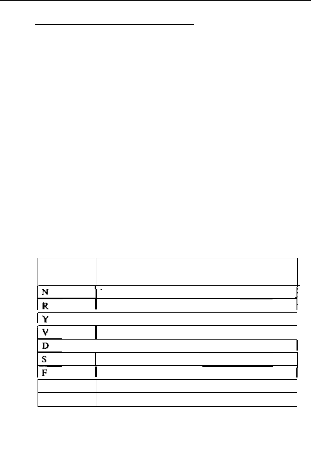
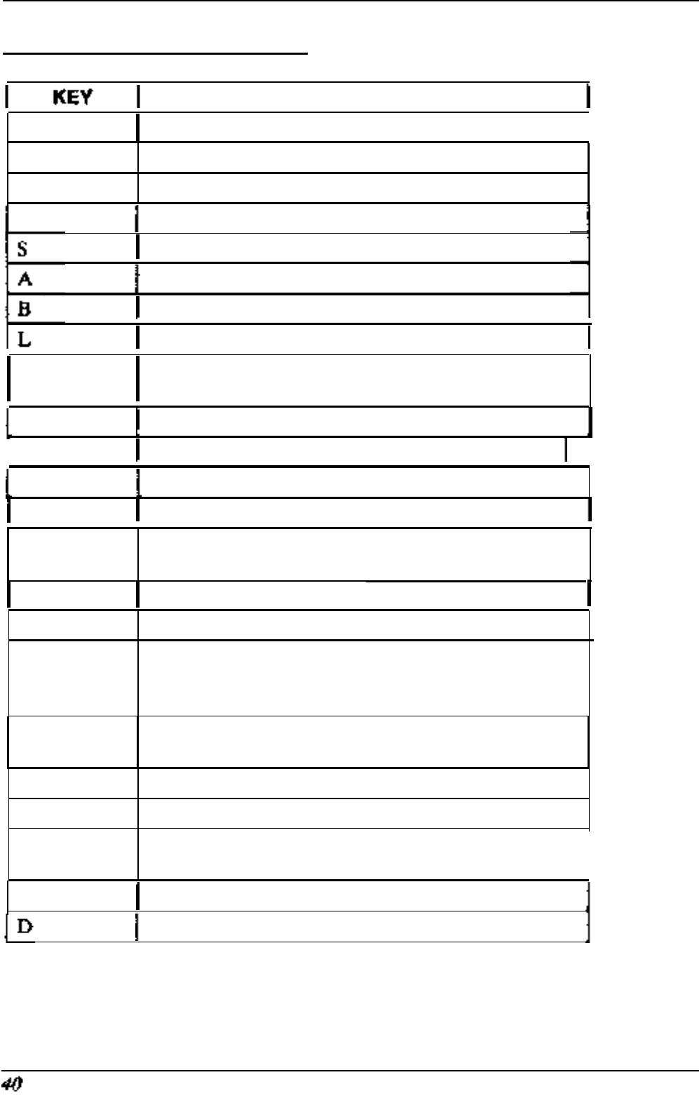
Select the appropriate formula for your application from the list below
Key Stroke Function
None
Do not display this entry
None
-
Do not use any formula on this entry
Red
-
Red thermistor formula
(6507A)
I
Yellow
-
Yellow thermistor formula (6507B)
I
Violet
-
Violet thermistor formula
(6507C)
I
Direction
-
Use the wind direction
formula
Use the soil moisture formula
(6513A)
Full scale
-
User defined full scale entry
H
Hi-Res Entry is a 2’s compliment 13 bit value
T Time
-
Decode the entry as a date and time
If formulas RYVS have been selected then the FTU will respond with a
prompt for the user to enter the value of the reference resistor used with the
transducer.
If the formulas FH have been selected then the FTU will prompt with a line
“Min value?”. The minimum desired
vaIue
for the scaling should then be
Section 7.
FTUC
COMMANDS
33
Field Test Unit Software
entered. The FTU will then prompt with “Max Value?”. The maximum
desired value for the scaling should then be entered. The FTU will now only
display values from the minimum to maximum for the selected memory loca-
tion/s.
After responding to the above prompts the
FTU
will prompt
“Using
#####”
This is a feature that enables the FTU to custom format the decimal struc-
ture and units for the displayed value.
EXAMPLE:
By typing the following to the USING prompt
“##.#
Celsius”
The FTU will display the memory value in the format
“34.4 Celsius”
If the screen is cleared beforehand, (SHIFT-HOME), this will be the only
information displayed by the
FTU.
For further information on “PRINT USING” see the Canon X-07 “Basic
Reference Manual” page 92.
7.4
MEMORY ADDRESSING
There are three ways to address memory within the logger using FTU-
PROM:
Block number
Location from start of current Block
Absolute address
7.5 CURSOR KEYPAD
Using the direction keys, the display may be shifted forward and backward
by one value, or by a given screen step. The screen step (STEPSIZE) is
usually set to one whole screen, calculated considering the size and mode
that is in effect.
The default STEPSIZE can be set by pressing “S”. The FTU will then
respond “Step size?” . The entered number will be the resultant number of
34 Section 7. FTUC COMMANDS

Field Test Unit Software
memory locations that the display will skip forward or backwards to when
the Up arrow or Down arrow is pressed.
This step size can be saved in a screen format file.
The SPACEBAR will reset the screen to its initial state.
7.6 SCREEN FORMAT FILES
The
FTU-PROM
has a feature that allows a custom designed screen format
file.
After designing a screen format using the
“E”
key the screen can be
saved by pressing the “W” (write) key. The
FTU
will then prompt for a file
name. After obtaining the file name the FTU will save the screen format and
resume working. 350 Bytes of RAM are required for each screen set up. The
screen formats and remaining memory can be viewed by pressing “F”. To
load in a new screen format press “R” followed by the
filename
of the desired
screen format.
Warning: Use of
a
filename containing the lett
ers “FTU” ma
y cause the
FTU to lock up on power on.
7.7
COMMANDS TO MODIFY DATA LOGGER
The FTU-PROM has the ability to display and modify the data loggers
memory. The appropriate commands and their functions are:
7.7.1 “P” - Put
This command allows the user to change the values of the loggers RAM
memory. Up to eight values can be changed at one command by typing con-
secutive values separated by comma’s.
EXAMPLE:
Press
“P”
FTU responds “?”
Type
O,O,O,O
<RET> <RET>
The value 0 will be entered in the RAM from the current address upwards.
i.e. If the FTU was at address
128
the value 0 should appear
in
address 128
-
132.
Section 7. FTUC COMMANDS 35

Field Test Unit Software
7.7.2
“T”
-
TIME
This command enables the user to check and/or reset the logger’s time and
date. The Canon X-07’s date and time MUST be set accurately for this pro-
cedure. If the Canon’s time/date needs to be changed type “t” to reset it, (see
below under X-07 Commands).
EXAMPLE:
Press
“T”
FTU
display responds:
10:58:28 10:45:21
87/05/29 87/05/28
logger canon
Press Return or Put
If the date on the logger side is as desired then press RETURN to exit. If
not the press Put
-
“P”
to set the logger’s date to that of the Canon.
7.7.3 “d” - DISPLAY *
This command causes the FTU to display current information from the log-
ger on:
• Cycle time of the logger
• Log size (number of bytes used per log)
• Log interval in minutes and seconds
• Time of the first log, the number of logs made and the
number of full days the logger has been recording
EXAMPLE:
Press shift-D
(“d”)
FTU display responds:
1 second logger
1 byte log size
1 min 0 second
log interval
First
log at
12:09:00 87/05/29
3 logs 0 days
press RETURN
36 Section 7. FTUC COMMANDS

Field Test Unit Software
7.7.4 “r” - RESET *
This command resets the logger data storage to an original state. All data is
lost and the logger starts logging immediately.
7.7.5 “j” & “a” - JUMP TO LOG & ADDRESS toggle *
These two commands are used together to view data in the logger memory.
By pressing
“j”
the user can access specific logs. Selection of a log number
will cause the FTU to display the logged data. Use of the cursor key pad
wilI
enable the user to move through the logs.
By pressing “a” the user can interchange the bottom line from an address dis-
play to that of the loggers time reading at each specific log. If the screen is
cleared and set up prior to entering
“j”
then the
FTU
will display the logged
data in actual units rather than raw bytes.
7.7.6 “D” - DATA
This command will cause the FTU to prompt “Data Buffer (0-7)”. After
receiving the desired buffer number the FTU will then display information
on that buffer pointer from the logger.
7.7.7 “J” - JUMP to ADDRESS
Jump to address pointed to by the start, end or current pointer, (this infor-
mation can be displayed by the above command). The user will be required
to enter in the desired buffer number (0-7). The user can select the current,
end or start buffer by pressing “S”-start,
“E”-end
or “C”-current.
7.8 X-07
DIRECT COMMANDS FROM FTU-PROM
7.8.1 “t” - TIME
To reset the X-07’s internal clock/calendar type “t”. The new date if required
is entered by writing over the old date and then pressing “RETURN”.
Section 7. FTUC COMMANDS
37

Field Test Unit Software
7.8.2 “F” - FREE
This command will display all files held in RAM and available memory.
(See X-07 manual for more details).
7.8.3 “Q” - QUIT
Pressing this key will return the X-07 to BASIC.
7.8.4
“b”
-
BAUD
This command will allow the user to set the FTU’s communication baud
rate. The default is 8000 baud. Users of remote telemetry systems should
consult their manual
6213
to decide on the
correct
baud rate if using a
MODEM.
7.8.5
“s”
-
S300
This command will cause the
FTU-PROM
to exit from normal communica-
tions with the logger and to assume a “dumb terminal” mode for communica-
tions with another terminal.
7.8.6
“x”
-
TRANSFER
This command will allow the FTU to transfer files between itself and an
IBM PC compatible using UNIDATA’s
PDL-FTU
software version
1.5
or
later. File transfer can be done in either direction. Once
“x”
has been
pressed all commands take place from the PC. See software manual 6201
“STARLOG Software Manual” for further details.

Field Test Unit Software
7.9 INDIRECT AND
MISCELLANEOUS
COMMANDS
7.9.1
“@”
- INDIRECT JUMP
Jump to the address pointed to by first 2 bytes on the screen.
Section 7.9 INDIRECT AND MISCELLANEOUS COMMANDS
39
Field Test Unit Software
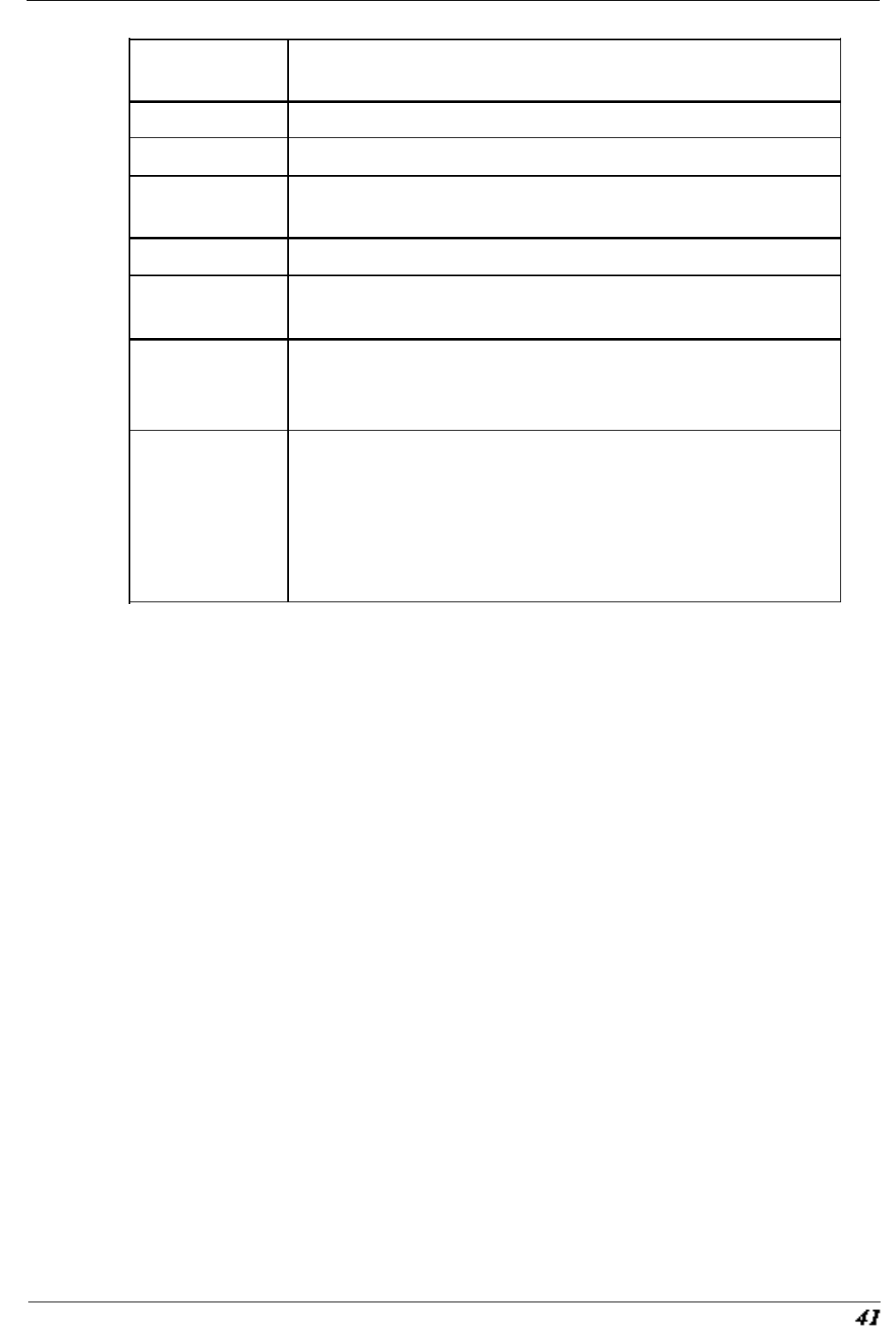
7.10 SUMMARY OF COMMANDS
FUNCTION
Right arrow Step Forward 1 byte of logger memory
I
Left arrow Step Backward
1
byte of logger memory
Down arrow Step Forward
STEPSIZE
bytes of logger memory
.
Up arrow
Step Backward
STEPSIZE
bytes of logger memory
Set the value of STEPSIZE
Move to a new ADDRESS of logger memory
Move to a new BLOCK of logger memory
Move to a new LOCATION within the current block
@
to the ADDRESS pointed to by the 1st 2 bytes on
the screen
T
Display and set logger TIME and DATE
I
t Set FTU time and date
Spacebar Reset the FTU screen to initial state
HOME
Clear and redraw the current screen
CLR
Clear (Shift/Home) the current screen of all entries
and instruments
H Display HELP
file
Q
I
Quit and go to BASIC
Select or add an instrument to the current display
screen
Enter the
catalog
number of instrument
followed by the input channel of each instrument.
E
Define an entry in the current display screen (See
User Defined Screen Format)
W Write (Save) the current screen setup
R Read a previously saved screen setup
F
Display list of current screen setups (and remaining
space for new setups)
I
P
Put data into logger memory
Display current data buffer pointers
(table continues on the next page)
Section 7.9 INDIRECT AND MISCELLANEOUS COMMANDS
Field Test Unit Software
J
Jump to address pointed by the (S)tart, (E)nd or
(C)urrent pointer
s
b
x
j
a
Set
FTU
to direct communication mode.
Set or change FI’U communication baud rate
Transfer programs between an IBM and X-07 using
PDLFTU
software
jump to a specific log entry
*
toggle ADDRESS display to TIME of current log
entry*
r
d
RESET the logger ready for another recording
session*
**
ALL RECORDED DATA WILL BE LOST
**
Display logger information on:
Cycle time
Log size
Log interval
Time of
first
log, number of logs made and the
number of full days the logger has been recording.*
Footnote: * indicates commands that require the logger to be programmed
with IBM software package
V#1.8
or later.
Section 7.9
INDIRECT AND
MISCELLANEOUS COMMANDS
