Capital Prospect SC001 Control Panel (433.92MHz Tx) User Manual G ACCESS sc100M3LENG PDF p65
Capital Prospect Ltd Control Panel (433.92MHz Tx) G ACCESS sc100M3LENG PDF p65
UserManual.wiki
>
Capital Prospect
>
SC001 User Manual
User Manual
Navigation menu
Upload a User Manual
Namespaces
Wiki Guide
HTML
PDF
Info
Views
User Manual
Discussion / Help
Navigation
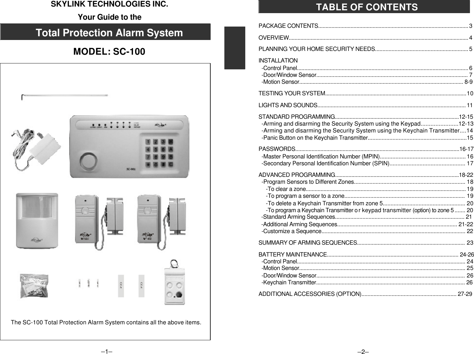
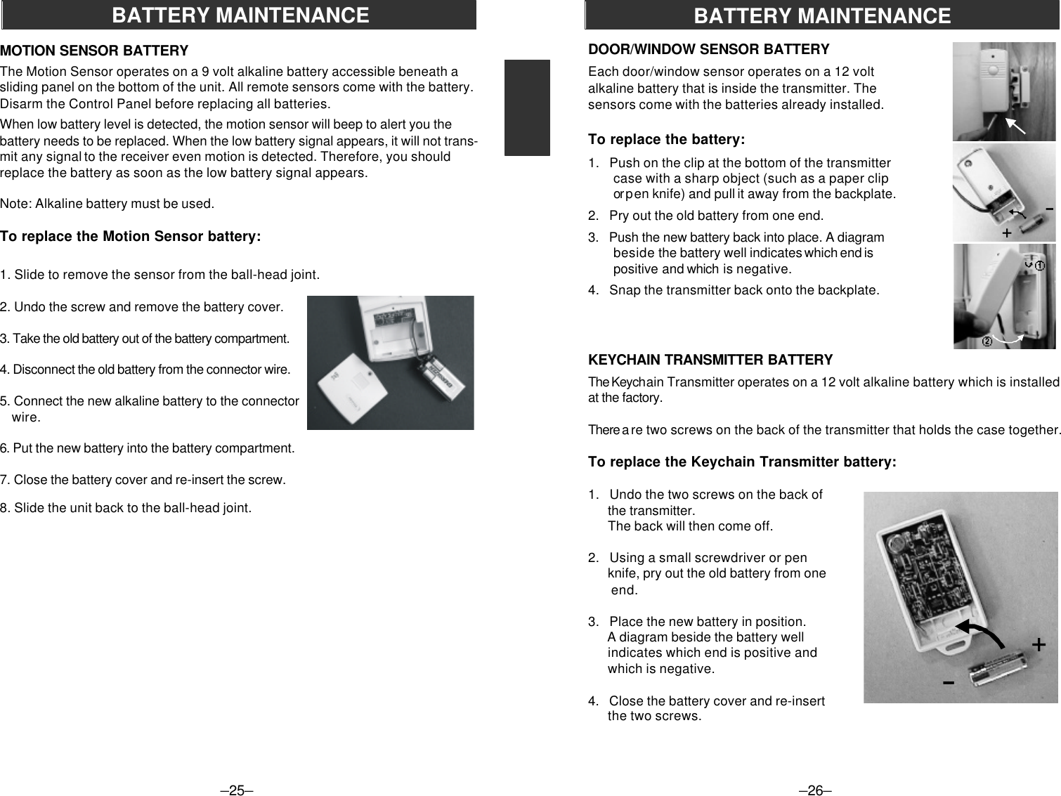
![–9–INSTALLATIONBefore you learn how to use your security system, test to make sure that the door/window sensors and the motion sensor are communicating with the Control Panel.Set the Control Panel to CHIME MODE which will emit a subtly two tone chimewhen any of the sensors are activated.To set control panel to CHIME MODE1. Enter your MPIN [0, 0, 0] on the Control Panel (MPIN is factory set at [0, 0, 0]. To change MPIN see MASTER PERSONAL IDENTIFICATION NUMBER (MPIN) on page 16.2. Press [ A ].3. Press [ # ].The red arm light and all 4 green lights above the numbers and beside the wordchime will go on. The system will now emit a chime sound when any sensor isactivated. The lights and sounds of the Control Panel are explained in the nextsection (see Lights and Sounds).The door/window sensors are factory set to communicate with zone 1 and themotion sensor to communicate with zone 2. If you would like to have the sensorscommunicate with a different zone, see PROGRAM SENSORS TO DIFFERENTZONES on page 18.To test the Door/Window SensorOpen the door/window and break the contact between the magnetic switch andthe magnet. A signal will then be sent to the Control Panel which will chimetelling you that the signal has been received. One of the four green lights on theControl Panel will flash once as the chime sounds. If you open the front door, thegreen light above the #1 (zone 1) will flash.To test the Motion SensorPower up the motion sensor. Walk in the monitored area in front of the motion sensor.Once movement is detected, a signal will be sent to the Control Panel. The ControlPanel will then emit a two tone chime and the green light above the #2 (zone 2)will flash once. The motion sensor has been programmed to send its signal tozone 2 in the Control Panel. It will take about 20 seconds for the motion sensor toreset itself before it can send another signal.If you have pets, have them walk in the monitored area to see if they activate themotion sensor. If so, turn the motion sensor off if these pets have access to themonitored area.–10–TESTING YOUR SYSTEMAC PWR LO BATT. ARMCHIMEDELAYINSTANT1 2 3 4 After mounting the sensor at the desired location, it isimportant to perform a walk test in order to determineif the sensor is detecting the things you want to detect.In order to control how far the sensor can “see”, this can be done by adjustingthe angle of the sensor. To reduce the detection range, simply move thesensor downward. To increase the range, move the sensor up to around 12degrees. This will give the maximum range. However, this may not be desiredif the sensor is placed outdoors, since a false trigger may occur if the sensor isset to detect motion in a distance.You should walk in the area that you would like the sensor to monitor. Entry theCHIME mode by pressing 000A# on the SC-001. The receiver will beep if thesensor detects your movement. If the sensor does not respond, adjust themounting angle accordingly. Perform the walk test again after 30 seconds.Repeat this procedure until your motion is detected. There should be nomovement in the detected area during the 30 seconds.Perform walk test in the undesired area to ensure movement cannot be detected.Tips: The sensor should not face towards direct sunlight, placing near heat or coldproducing devices (i.e. A/C or furnance vents, fans, ovens, heaters etc.) that maycause false triggers.WALK TEST12ºMove the sensor downward toreduce the range. Move the sensor up to around12 º to give maximum range.](https://usermanual.wiki/Capital-Prospect/SC001/User-Guide-744215-Page-7.png)
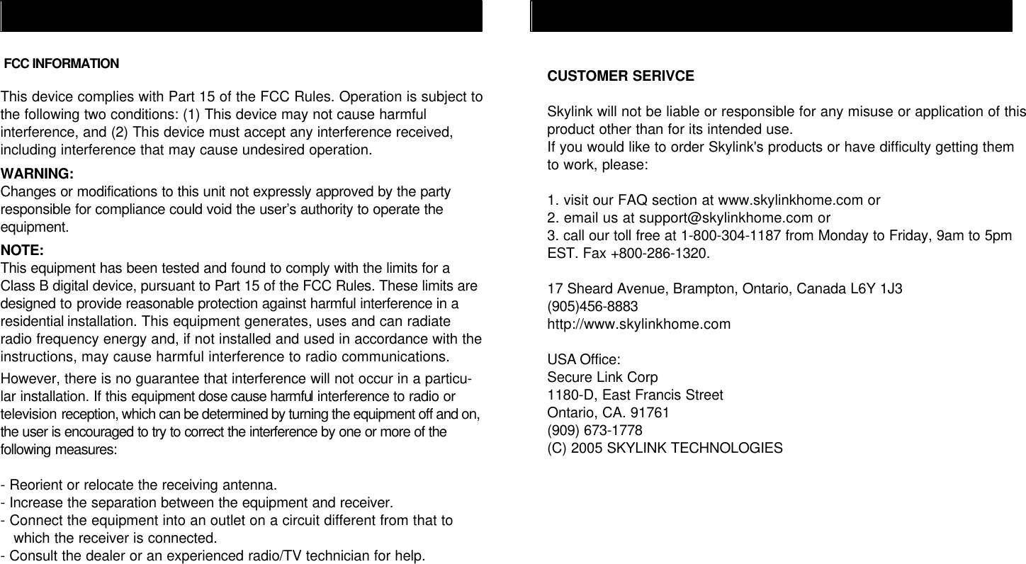
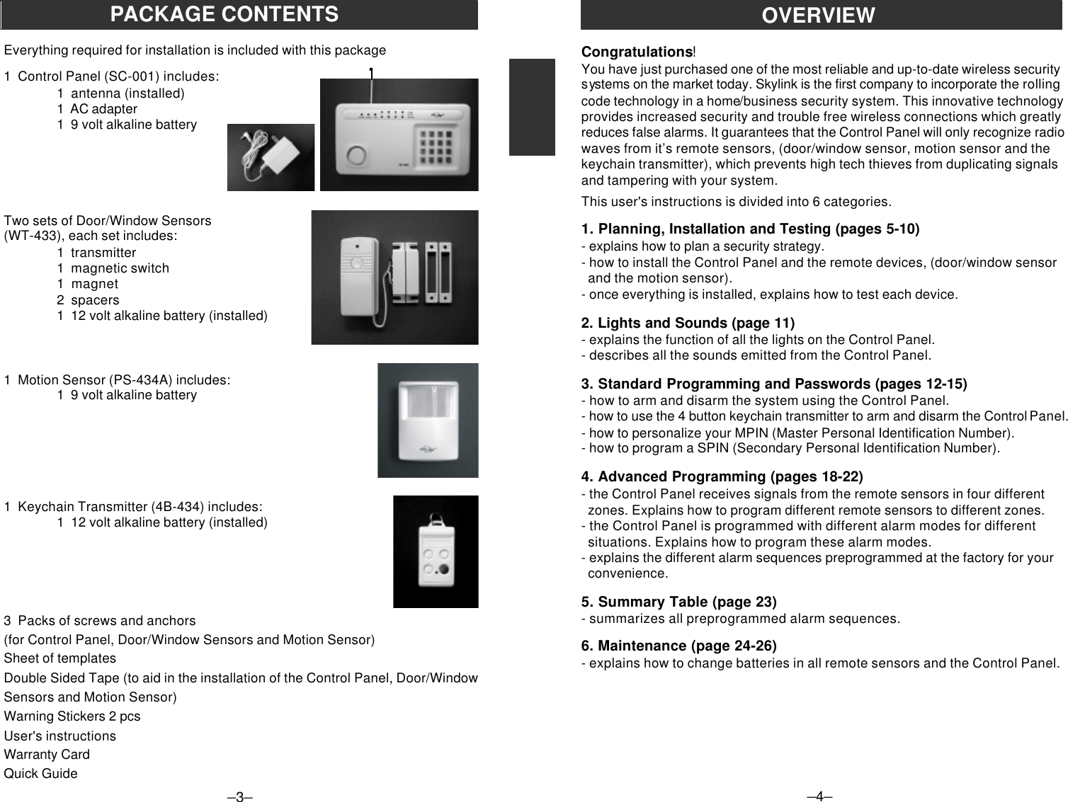
![If you make a mistake while programming, the Control Panel emits three shortbeeps. That means the system has cleared and you must start the programmingsequence from the beginning. If you get lost in the programming sequence orhave made a mistake and want to start over again, press the [ * ] on the key padof the Control Panel until you hear three short beeps. This will clear the system,then you can start again from the beginning. If no button is pressed for eightseconds while in the middle of a programming sequence, the system will alsoclear itself.–11–LIGHTS AND SOUNDSBelow is an explanation of the lights and sounds of the Control Panel.LIGHTSACPWR light on System is being powered by electrical current.ACPWR light off System is not receiving any electrical power.LOBATT. light off Backup battery is connected and working.LOBATT. light flashing Backup battery is weak, needs to be replaced.ARM light off System is disarmed.ARM light on System is armed.Key Pad Back Light If powered by AC adapter - back light is always onIf powered by back up battery only - stays on for eightseconds when any button is pressed.Green lights above #1-4 System will emit a two tone chime when a sensor isactivated, CHIME MODE.Red lights below #1-4 System will sound alarm instantly when a sensor isactivated, INSTANT MODE.Both green and red lights System will beep steadily for 30 seconds when a#1-4 sensor is activated, after the 30 seconds the alarmwill sound, DELAY ENTRY MODE.Both green and red lights Lights will flash for 45 seconds. All remote sensors pro-flashing grammed to that zone will not communicate with theControl Panel for those 45 seconds, which gives youtime to exit the premises before the system is armed.SOUNDSThree short beeps You have made a mistake, start again.Long beep You have successfully completed a command.Short beep You have pressed a key in the right order.Two tone chime A device has been activated in CHIME MODE.Siren (3 minutes) A device has been activated in INSTANT MODE.Steady repeated beep The alarm has been triggered in DELAY MODE.You have 30 seconds to disarm the system beforethe alarm sounds.Two tone beep System is set on exit delay, you have 45 secondsto leave the premises once the system has beenactivated. After the 45 seconds, the system emitsa two tone beep and the system is now armed.Now that the system is installed and the sensors are communicating with theControl Panel, it is time to learn how to do basic programming of your securitysystem. More advanced features are explained further in the manual, (seeAdvanced Programming).You can arm and disarm the system by using either the keypad on the ControlPanel or the 4 button keychain transmitter or keypad transmitter KP-433 (option).TO ARM THE SYSTEM USING THE KEYPAD ON THE CONTROL PANELAll programming sequences begin with the Master Personal Identification Numbe r(MPIN). There is only one MPIN which has been factory set at 0 0 0. You can alsoassign up to 3 different Secondary Personal Identification Numbers (SPIN). Formore information on how to change your MPIN and how to add an SPIN, (seePASSWORDS on page 16, 17).We have preprogrammed 6 different arm sequences to meet different circumstances.For example, if you would like the system activated while you are in the premises,the motion sensor will be turned off so you have the freedom to move about with-out setting off the alarm. You can personalize any of these preprogrammed armsequences, (see Advanced Programming).Arming sequencesOption 1: Away Sequence - To arm your system when you are the last personleaving the premises.1. Press the current MPIN [ 0 0 0 ].2. Press [ B ].3. Press [ C ].You hear a long beep. The arm light and the red lights in zones 3 and 4 go on.Both the green and red lights flash in zone 1 for 45 seconds which gives you 45seconds to leave the premises before the system is activated. After 45 seconds,both the green and red lights in zone 1 and 2 remain on. Upon re-entering thepremises through zone 1, or walking in the monitored area of the motion sensor,zone 2, you have 30 seconds till the alarm sounds. The system gives you 30seconds from the time you enter the premises, for example opening the front door,to get to the Control Panel to deactivate the system. Zones 3 or 4 remain instant.If any sensor in zone 3 and 4 are activated, the alarm sounds instantly.Option 2: Home Sequence - To arm your system when someone remains in thepremises.1. Press the current MPIN [ 0 0 0 ].2. Press [ C ].–12–STANDARD PROGRAMMING](https://usermanual.wiki/Capital-Prospect/SC001/User-Guide-744215-Page-8.png)
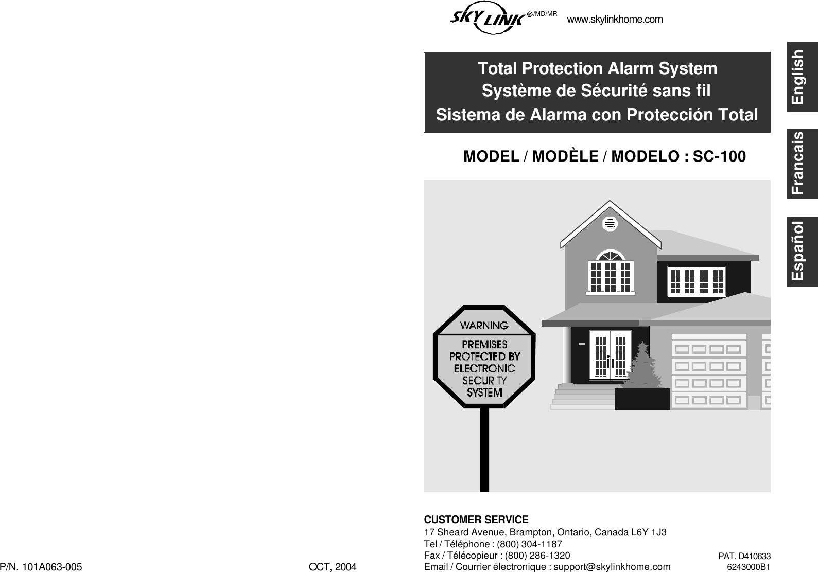
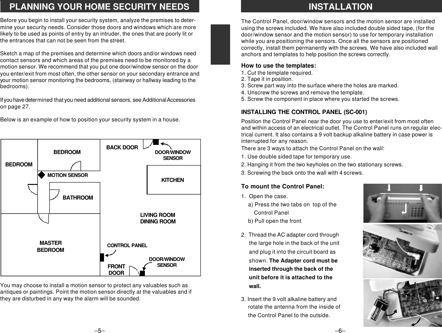
![–13–STANDARD PROGRAMMINGYou hear a long beep. The arm light and the red lights in zones 3 and 4 go on.Both the green and red lights flash in zone 1 for 45 seconds which gives you 45seconds to leave the premises before the system is activated. After 45 seconds,both the green and red lights in zone 1 remain on. Upon re-entering the premisesthrough zone 1, you have 30 seconds till the alarm sounds. The system givesyou 30 seconds from the time you activate the door/window sensor, for exampleopening the front door, to get to the Control Panel to deactivate the system. Zone2 remains off which allows the person in the premises to move around withoutactivating the motion sensor. Zones 3 and 4 remain instant. If any sensor in zone3 or 4 are activated, the alarm sounds instantly.Option 3: Night Sequence - To arm your system when there are people in thepremises and no one is expected to enter or exit. Example at night when every-one is sleeping.1. Press the current MPIN [ 0 0 0 ]. 2. Press [ A ].3. Press [ B ].You hear a long beep. The arm light, the red light in zones 1, 3 & 4 go on. If any ofthe sensors are activated in any of these 3 zones, the alarm is sounded instantly.Zone 2, the motion sens or, remains off allowing movement th roughout the premises.TO DISARM THE SYSTEM USING THE KEYPAD ON THE CONTROL PANEL1. Press the current MPIN [ 0 0 0 ].2. Press [ # ].All the lights but the AC PWR light go off. The system is now disarmed.Note: If [MPIN,#] is entered when the system in not activated, the system willdefault back to the last sequence before the unit was turned off.Emergency Silent Alarm works in conjunction with the Emergency Dialer AD-433S(option), see Additional Accessories.If under duress when disarming the system:1. Enter the current MPIN [ 0 0 0 ].2. Press [ B ] [ B ].This will terminate the delay mode (stop the steady repeated beep) and return tothe previous arm mode. It will also send a signal to the Emergency Dialer silentlywhich will then automatically send a prerecorded message for help.Note: Do not use Emergency Silent Alarm [PIN], [B], [B] if your Skylink securitysystem includes the Audio alarm AA-433, since the Silent alarm is not designedto work with AA-433, which means [PIN], [B], [B] will sound the siren of the AA-433instantly.TO ARM SYSTEM USING THE KEYCHAIN TRANSMITTERThere are 2 different arm options to choose from:1. Press button #1, and the Control Panel will beep once.The system will be armed in the Away Sequence. To be used to arm the systemwhen you are the last person leaving the premises. (see page 12 for informa-tion on the Away Sequence).Pressing button #1 will give you the same result as pressing:MPIN, [ B ] , [ C ] on the keypad.2. Press button #2, and the Control Panel will beep once.The system will be armed in Home Sequence. To be used to arm the systemwhen someone remains in the premises. (see page 12 for information onthe Home Sequence).Pressing button #2 will give you the same result as pressing: MPIN, [ C ] on thekeypad.The Keychain Transmitter conveniently fits on any keychain. It allows you to armand disarm the system from a distance of approximately 100 feet from the ControlPanel. The distance will depend on what is between the keychain transmitter andthe Control Panel. It also has a panic button that lets you remotely activate thesiren instantly.Note: Make sure you press down on the transmitter for one full second or thesystem may not respond.–14–PANIC2 1 3KEYCHAIN TRANSMITTER (4B-434)](https://usermanual.wiki/Capital-Prospect/SC001/User-Guide-744215-Page-9.png)
![–15–KEYCHAIN TRANSMITTER (4B-434)TO DISARM THE SYSTEM, OR DEACTIVATE THE SIREN USING THEKEYCHAIN TRANSMITTERWhen the system is armed:Press button #3.The red light on the transmitter flashes and the Control Panel beeps twice.The system is now disarmed.When the siren is sounding:Press button #3.The red light on the transmitter flashes and the siren is deactivated.THE PANIC BUTTON ON THE KEYCHAIN TRANSMITTERBoth the Control Panel and the keychain transmitter are equipped with panicbuttons. It doesn’t matter what mode you are in or even if the system is off, onceeither panic button is pressed, the siren comes on instantly. The alarm will continueto sound for 180 seconds or until the system is disarmed.The panic button on the keychain transmitter is the larger red button.The panic button on the Control Panel is the red button on the keypad.–16–PASSWORDSMASTER PERSONAL IDENTIFICATION NUMBER (MPIN)Security access to the SC-100 is controlled by a MASTER PERSONAL IDENTIFI-CATION NUMBER (MPIN) or SECONDARY PERSONAL IDENTIFICATIONNUMBER (SPIN). All programming sequences start with either the MPIN or SPIN.To Change your MPIN:1. Enter the current MPIN (the MPIN is factory preprogrammed with 0 0 0).2. Press [ * ].3. Press [ 0 ].4. Press [ * ].5. Enter your new MPIN, (your MPIN must be a minimum of 3 digits).6. Press [ * ].If the system accepts the new MPIN, you will hear a long beep.If you hear three short beeps, the system did not accept the new MPIN.Start again from the beginning.Note: If you enter an incorrect MPIN or SPIN, the alarm will sound after the forthincorrect attempted.Note: If you forget the current MPIN, unplug the Control Panel and remove thebattery. The MPIN will automatically return to the factory default of 0 0 0. Make surethe unit is disarmed when you open the Control Panel. The Control Panel hasa built in Defence System. When the unit is armed and the Control Panel isopened or vandalized, the alarm will sound and send a signal to the emergencydialer (if applicable). For more information on the Emergency Dialer see Addi-tional Accessories. (page 27)](https://usermanual.wiki/Capital-Prospect/SC001/User-Guide-744215-Page-10.png)
![–17–SECONDARY PERSONAL IDENTIFICATION NUMBER (SPIN)You may want to give someone limited access to the system, (baby sitter, cleaner,repairman etc.). For this purpose the SC-100 provides you with the option ofadding up to 3 separate SPIN.A SPIN can be any number of 3 digits or more. You can use a SPIN to arm anddisarm the system but not to program it, (programming is explained in the nextsection). When someone no longer needs to have access to your security system,you can simply delete their SPIN.Adding a SPIN1. Enter the current MPIN.2. Press [ * ].3. Press the number key to identify user, either [ 1 ], [ 2 ] or [ 3 ].4. Press [ * ].5. Enter the new SPIN ( your SPIN must be a minimum of 3 digits).6. Press [ * ].If the system accepts the new SPIN, you will hear a long beep. If you hear threeshort beeps, the system did not accept the new SPIN. Start again.Deleting a SPIN1. Enter the current MPIN.2. Press [ * ].3. Press the number to identify the user, either [ 1 ], [ 2 ] or [ 3 ].4. Press [ * ].5. Press [ * ] one final time.If the SPIN was successfully deleted, you will hear a long beep.PASSWORDS–18–ADVANCED PROGRAMMINGPROGRAM SENSORS TO DIFFERENT ZONESYou now have a basic understanding of how the SC-100 security system works.In this section, we will explain how to move sensors to different zones, how tochange the alarm modes (for example from Instant Mode to Delay Mode), andhow to customize the pre-programmed arm sequences (for example if you onlyuse one door to enter/exit from, your secondary door should communicate witha zone that is in instant mode).Your SC-100 Security System is divided into five zones. The 1st four zones aredisplayed on the Control Panel as 4 pairs of lights, one green and the other red.When a remote sensor (door/window sensor or motion sensor) is activated,it sends a signal to one of the 1st four zones on the Control Panel. Each zonecan communicate with as many as six sensors. The Control Panel can com-municate with a maximum of 24 different sensors.The fifth zone, (which is not represented by any lights on the Control Panel), isprogrammed to communicate with Keychain Transmitters. Zone 5 can accommo-date a maximum of six Keychain Transmitters 4B-434 or Keypad transmittersKP-433 (option).You can assign your remote sensors to whatever zones you want. For yourconvenience, we have preprogrammed the remote sensors for you. Both door/window sensors are assigned to zone 1 and the motion sensor is assignedto zone 2.You may wish to program a sensor to communicate to a different zone. Forexample: if you do not enter/exit from your back door, you may want to changethe zone s o that the door sensor is communicating with a different zone. Currently,this sensor is communicating with zone 1, but if you change it so it will becommunicating with zone 3, the alarm will now sound instantly. You may havea premises with three enter/exit doors. You will need additional door/windowsensors, (see Additional Accessories on page 27).](https://usermanual.wiki/Capital-Prospect/SC001/User-Guide-744215-Page-11.png)
![–19–ADVANCED PROGRAMMINGTo program sensors to send their signals to a different zone, you must first clearthem from communicating with their current zone.TO CLEAR A ZONE1. Enter the current MPIN.2. Press [ B ].3. Press the number key to identify current zone [ 1, 2, 3 or 4 ]. The zone light(s) will flash for eight seconds.4. While the zone light(s) are flashing, press [ * ]. Now both the green and red lights flash for 30 seconds.5. Do not activate any sensors while these lights are flashing. Once the lights stop flashing, the zone is cleared of all devices.Now that you have cleared the zone from communicating with all sensors, programthe sensors to the zones you would like them to communicate with (see below).TO PROGRAM A SENSOR TO A ZONE:1. Enter the current MPIN.2. Press [ B ].3. Press the n umber key to identify w hich zone to add the sensor to, zone [ 1, 2, 3 or 4 ]. The zone light(s) will flash for eight seconds.4. While the zone light(s) are flashing, press [ * ]. Now both the green and red lights flash for 30 seconds.5. While the zone lights are flashing, go to the remote sensor you are adding and activate it. Walk in front of the motion sensor or open the door/window.You will hear a long beep, the zone light will stop flashing and the remote sensorwill now communicate to that zone.Note : You can only add remote devices to a zone one by one, but you can notremove them one by one. You must clear all sensors from the zone and add backthe ones you want.TO PROGRAM THE MOTION SENSOR TO THE SECURITY CONTROLPANEL (SC-001):1. Power up the motion sensor.2. Enter the current MPIN (Master Personal Identification Number).3. Press [B].–20–4. Press the number key to identify which zone to add the Motion Sensor to [1, 2, 3 or 4]. We recommend you program the motion sensor to zone 2. The zone light will flash for eight seconds.5. While the zone light is flashing, press [ * ].6. While the zone light is flashing, press the learning button inside the batterycompartment of the Motion Sensor in order to activate it. You will hear a longbeep if the motion sensor is “learned” to the control panel. The zone light willstop flashing and the remote sensor will now communicate to that zone.TO DELETE A KEYCHAIN TRANSMITTER FROM ZONE 5:1. Enter the current MPIN.2. Press [ B ].3. Press [ 5 ].4. Press [ * ].5. Do not activate any Keychain Transmitters or sensors for 30 seconds after the [ * ] was pressed.You have now cleared zone 5 from communicating with all Keychain Transmitters.Please re-program the keychain transmitters that you would like to use by thefollowing instruction.TO PROGRAM A KEYCHAIN TRANSMITTER OR KEYPAD TRANSMITTER(OPTION) TO ZONE 5:1. Enter the current MPIN.2. Press [ B ].3. Press [ 5 ].4. Press [ * ].5. Within 30 seconds of pressing the [ * ], press any of the four buttons on the Keychain Transmitter OR press the panic button on the Keypad Transmitter.You will hear a long beep and the Keychain Transmitter will now communicatewith zone 5.NOTE: Zone 5 is designated for keychain and keypad transmitter ONLY.Please do not program any sensors other than keychain and keypad transmittersinto zone 5, otherwise the system will not work properly.ADVANCED PROGRAMMING](https://usermanual.wiki/Capital-Prospect/SC001/User-Guide-744215-Page-12.png)
![–21–ADVANCED PROGRAMMINGSTANDARD ARMING SEQUENCESEach zone can be programmed to react 5 different ways when it receives a signalfrom a remote sensor.1. Chime Mode - represented by the green lightsWhen only the green light is on and the Control Panel receives a signalfrom a remote sensor, the Control Panel emits a subtly two tone chime.2. Instant Mode - represented by the red lightsWhen only the red light is on and the Control Panel receives a signal fromthe remote sensor, the Control Panel will activate the siren instantly.3. Delay Entry Mode - represented by the green and red lightsWhen both the green and red lights are on and the Control Panel receivesa signal from a remote sensor, the lights will flash and the Control Panelwill beep for 30 seconds before the alarm sounds. These 30 secondsgive you time to enter the premises and deactivate the alarm before thesiren sounds.4. Delay Exit Mode - represented by the flashing of both the green and red lights for 45 secondsWhen both green and red lights are flashing, the control panel will notrecognize any remote sensors communicating to that zone. These 45seconds allow you time to exit the premises before that zone is activated.When the lights stop flashing, both green and red lights will remain on,which is now in DELAY ENTRY MODE.(See above for information on DELAY ENTRY MODE).5. Off - neither the green nor the red lights are on.The Control Panel will not recognize any signals from a remote sensor.We have preprogrammed different combinations of the above modes to meetdifferent situations, (see STANDARD PROGRAMMING).ADDITIONAL ARMING SEQUENCESBelow are three additional programming options you may want to use.Option 1: Advanced Home 1 - use to secure the premises while staying in thebuilding. Delays the alarm to allow someone to enter the building and deactivatethe alarm.1. Enter the current MPIN.2. Press [ A ].3. Press [ A ].You will hear a long beep. The arm light, the red and green lights in zones 1 andthe red lights in zones 3 and 4 go on. Zone 1 has the entry delay to allow some-one to enter through the front door and deactivate the system before the sirensounds. This option does not have the exit delay so you are not able to leave the–22–ADVANCED PROGRAMMINGpremises without activating the alarm. Zone 2 (the motion sensor), is off allowingmovement in the premises and zones 3 & 4 are instant.Option 2: Advanced Home 2 - use to secure the premises while staying in thebuilding. Delays the alarm to allow someone to enter the building and/or walk inthe monitored area of the motion sensor to deactivate the alarm.1. Enter the current MPIN.2. Press [ A ].3. Press [ C ].You will hear a long beep. The arm light, the red and green lights in zones 1 and 2as well as the red lights in zones 3 and 4 go on. Zone 1 & 2 has the entry delay toallow someone to enter through the front door and walk in the area monitored bythe motion sensor and deactivate the system before the siren sounds. This optiondoes not have the exit delay so you are not able to leave the premises withoutactivating the system. Zones 3 & 4 are instant.Option 3: Chime Sequence - this sequence is used for testing the system but itcan also be used to subtly alert you when a zone has been activated. Example, ifa young child opens the front door, the Control Panel will emit a two tone chimeadvising you that the front door has been opened. (See page 10 for programminginformation for the CHIME SEQUENCE.)The three arm sequences above ; Advanced Home 1, Advanced Home 2 andChime Sequence along with the three sequences described in the STANDARDPROGRAMMING; Away Sequence, Home Sequence and Night Sequence, makeup the six preprogrammed arm sequences.However, if any of these six sequences do not satisfy your needs, you may wantto change the modes in certain zones. For example, your zone 2, (motion sensor)is currently in delay mode. If your motion sensor is located in the basement andyou would like to change it to the instant mode, see below.TO CUSTOMIZE A SEQUENCE:Program the system to the sequence you want to alter.1. Enter the current MPIN.2. Press [ B ].3. Press a number key to select the zone you would like to change, [ 1, 2, 3 or 4 ]. The zone lights in the chosen zone will flash for eight seconds.4. While the lights flash, press [ A ].5. Select the new mode you want to use: [ 0 ] = Disarm, [ 1 ] = Chime Mode, [ 2 ] = Delay Entry/Exit Mode, [ 3 ] = Instant Mode6. Press [ * ].A long beep signals a successful change.](https://usermanual.wiki/Capital-Prospect/SC001/User-Guide-744215-Page-13.png)
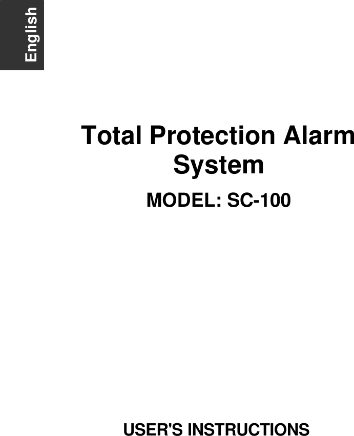
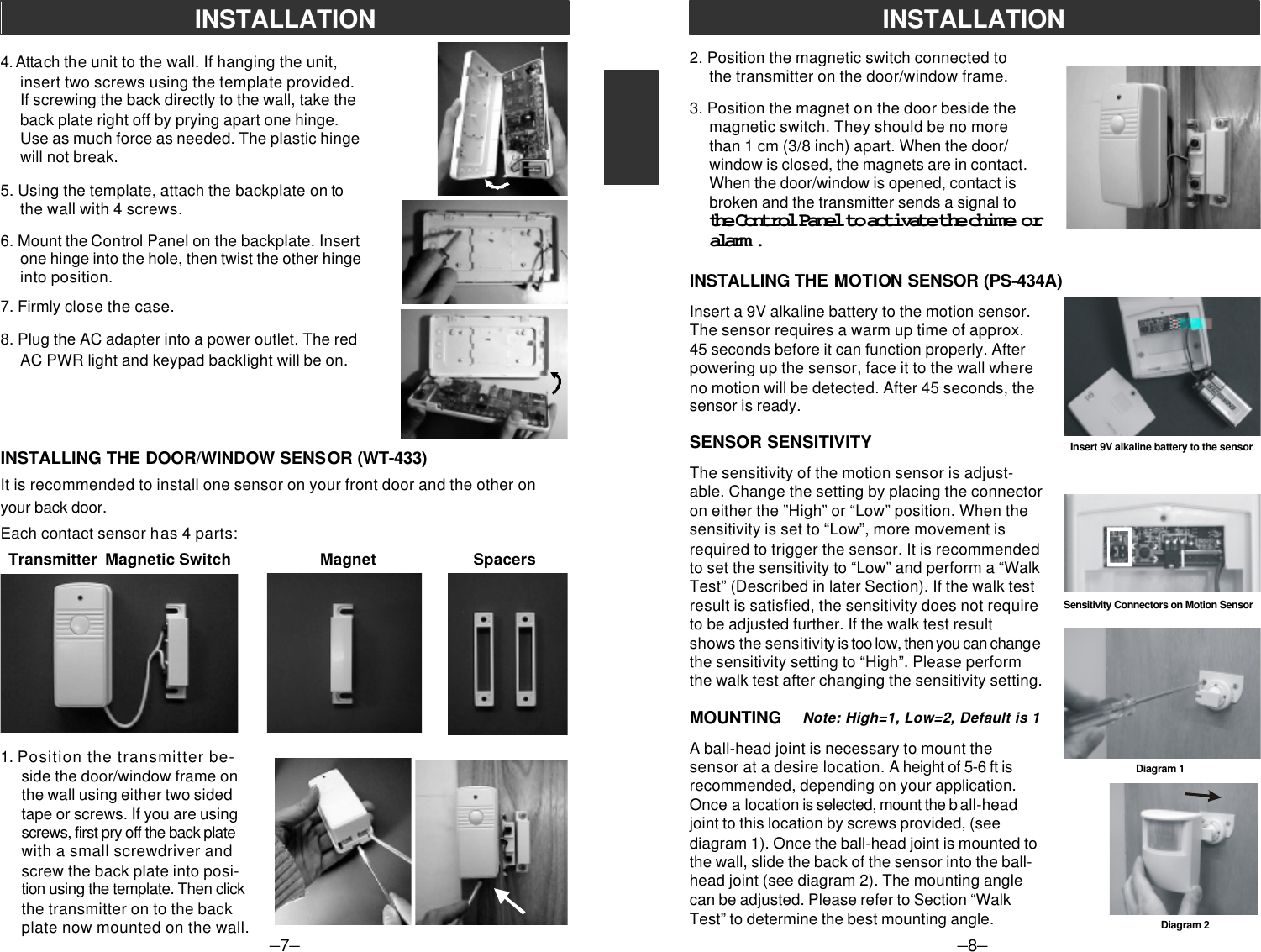
![–23–Below is a table summarizing all the preprogrammed sequences.Sequence Zone 1 Zone 2 Zones 3 & 4 When s equence should be used FOR TESTINGMPIN A # chime chime chime use for testing after installationand to test batteries, also use asa subtle chime when a remotesensor has been activated BASIC PROGRAMMINGMPIN B C exit delay off instant use when leaving the premises(after 45 sec.)entry delay entry delay instant and no one is insideMPIN C exit delay off instant use w hen leaving the premises(after 45 sec.) and someone is inside thepremisesMPIN A B instant off instant use when people are in thepremises and no one is expectedto enter/exitMPIN # off off off turns off the systemNote: when MPIN # is enter and the system is already off, the system will defaultback to the last sequence before the unit was shut off ADVANCED PROGRAMMINGMPIN A A entry delay off instant someone is in the building andsomeone is expected to enter/no exit delayMPIN A C entry delay entry delay instant person staying in the premisesis setting the alarm and will notwalk in the area monitored by themotion detectorPanic button - The SC-100 has 2 panic buttons, (the red buttons on the keychaintransmitter and on the Control Panel). The alarm will sound instantly when eitherof these buttons are pressed whatever mode you are in.Emergency Silent Alarm (works in conjunction with the Emergency Dialer option) -When disarming the system under duress, enter your MPIN, then press [ B ], [ B ].This will terminate the delay mode and return to the previous arm mode, as wellas send a signal to the Emergency Dialer, which will then send pre-recordedmessages for help. Do not activate this sequence if your Skylink security systemcontains the Audio Alarm AA-433. Since it will sound the siren of the AA-433instantly.When both power sources are removed from the Control Panel, (the AC adapteris unplugged and the battery is removed), all sequences will return to the abovefactory default.SUMMARY OF ARMING SEQUENCESThe SC-100 Security System comes with 5 batteries that at some point you mayhave to replace:19 volt alkaline battery for the Control Panel19 volt alkaline battery for the Motion Sensor212 volt alkaline batteries for the 2 Door/Window Sensors112 volt alkaline battery for the Keychain TransmitterRecommendation: Test you system periodically to ensure that all batteries areworking.CONTROL PANEL BATTERYThe Control Panel comes equipped with a backup battery in case the electricalpower is interrupted for any reason.When the Control Panel battery is low, the LOBATT. light goes on. Also, when theLOBATT. light is on and if you press any key on the keypad, 10 beeps warn youthat the battery needs to be changed.To replace the Control Panel backup battery:1. Disarm the unit.2. Open the Control Panel case by pressing down on the two tabs on the top edge and pull the front forward.3. Disconnect the old battery.4. Connect the new battery.5. Close the Control Panel.Note: To guard against sabotage, the Control Panel is equipped with an emer-gency switch that activates the alarm instantly when the case is opened. Makesure that the unit is disarmed when you open the case or you will activate thealarm.The battery life, (9 volt alkaline battery), is approximately two years if used onlyfor backup.Note: If the AC adapter is disconnected while the battery is replaced, the securitysystem will erase all the modifications that have been made and return to thefactory default. Also, your MPIN will return to 000.–24–BATTERY MAINTENANCE](https://usermanual.wiki/Capital-Prospect/SC001/User-Guide-744215-Page-14.png)